
Viper AS710 - Sweeper NILFISK - Free user manual and instructions
Find the device manual for free Viper AS710 NILFISK in PDF.
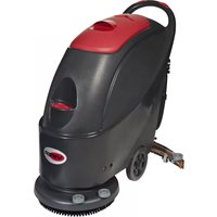
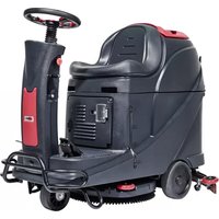
| Type | Ride-on floor scrubber |
| Model | Viper AS710R |
| Dimensions (L × W × H) | 1580 × 760 × 1230 mm |
| Net weight | 225 kg |
| Gross weight | 400 kg |
| Batteries | 4 × 245 Ah (20 h), 24 V |
| Charger | 24 V, 25 A |
| Brush motor | 2 × 300 W |
| Suction motor | 500 W |
| Drive motor | 500 W |
| Maximum speed | 6 km/h |
| Solution tank capacity | 120 L |
| Recovery tank capacity | 120 L |
| Working width (brushes) | 2 × 355 mm (diameter) |
| Squeegee width | 940 mm |
| Productivity | 4413 m²/h |
| Sound level | 69 dB(A) |
| Maximum slope | 10 % |
| USB port | 5 V, 0.8 A |
| Safety | Emergency stop (A15 button), seat switch, motor overload protection |
| Maintenance | Daily cleaning of squeegee, brushes, filters; lubrication after 8 h; check squeegee blades |
| Included accessories | User manual, battery charger, cables, squeegee, 2 brushes, brush holder |
Frequently Asked Questions - Viper AS710 NILFISK
User questions about Viper AS710 NILFISK
0 question about this device. Answer the ones you know or ask your own.
Ask a new question about this device
Download the instructions for your Sweeper in PDF format for free! Find your manual Viper AS710 - NILFISK and take your electronic device back in hand. On this page are published all the documents necessary for the use of your device. Viper AS710 by NILFISK.
USER MANUAL Viper AS710 NILFISK
natural_image
Technical line drawing of a cleaning or cleaning machine (no text or symbols present)Model # ____
Serial No.#
VR10029EU
REV.12 2022-03
Manufacturer / Výrobce / Hersteller / Fabrikant / Fabricante / Κατασκευαστής / Gyártó / Proizvođač / Fabbricante / Gamintojas / Ražotājs / Produsent / Fabrikant / Fabricante / Producent / Producător / производитель / Tillverkaren / Výrobca / Proizvajalec/ Üretici firma:
Nilfisk A/S, Kornmarksvej 1
DK-2605 Broendby, DENMARK
Product / Produkt / Producto, Toode, Produit, Tuote/ Produkt / Ppoïov / Termék / Proizvod / Prodotto / Produktas / Produkts / Artikel / Produtos / Produs / Izdelek / Ürün
AS710R, AS850R
Description / Popis / Beschreibung / Beskrivelse / Descripción / Kirjeldus / La description / Kuvaus / Oписание / Перурафń / Leirás / Opis / Descrizione / Apraśymas / Apraksts / Beschrijving / Descrição / Descriere / Beskrivning / Popis / Açıklama
FC - Floor Scrubber/Sweeper - Battery
Charging mode: 100-240V 50/60Hz;
Working mode: 24V DC, IP24

We, Nilfisk hereby declare under our sole responsibility, that the above mentioned product(s) is/are in conformity with the following directives and standards.

Authorized signatory:
Lars Gjødsbøl, Executive Vice President Global Products & Services
Oct 23, 2018

UK Declaration of Conformity
We,
Nilfisk Ltd
Nilfisk House, Bowerbank Way Gilwilly Industrial Estate
Penrith Cumbria
CA11 9BQ UK
Hereby declare under our sole responsibility that the
Product: FC - Floor Scrubber/Sweeper - Battery
Description: Charging mode: 100-240V 50/60Hz; Working mode: 24V DC, IP24
Type: AS710R*, AS850R*
Are in compliance with the following standards:
EN 60335-1:2012+A11:2014+A13:2017
EN 60335-2-72:2012
EN 55014-1:2017+A11:2020
EN 55014-2:2015
EN 61000-3-2:2014
EN 61000-3-3:2013
Following the provisions of:
Supply of Machinery (Safety) Regulations 2008/1597
Electromagnetic Compatibility Regulations 2016/1091
Penrith, 07-06-2021

Stewart Dennett
GM/MD
TABLE OF CONTENTS
ENGLISH USER MANUAL.... 1-17

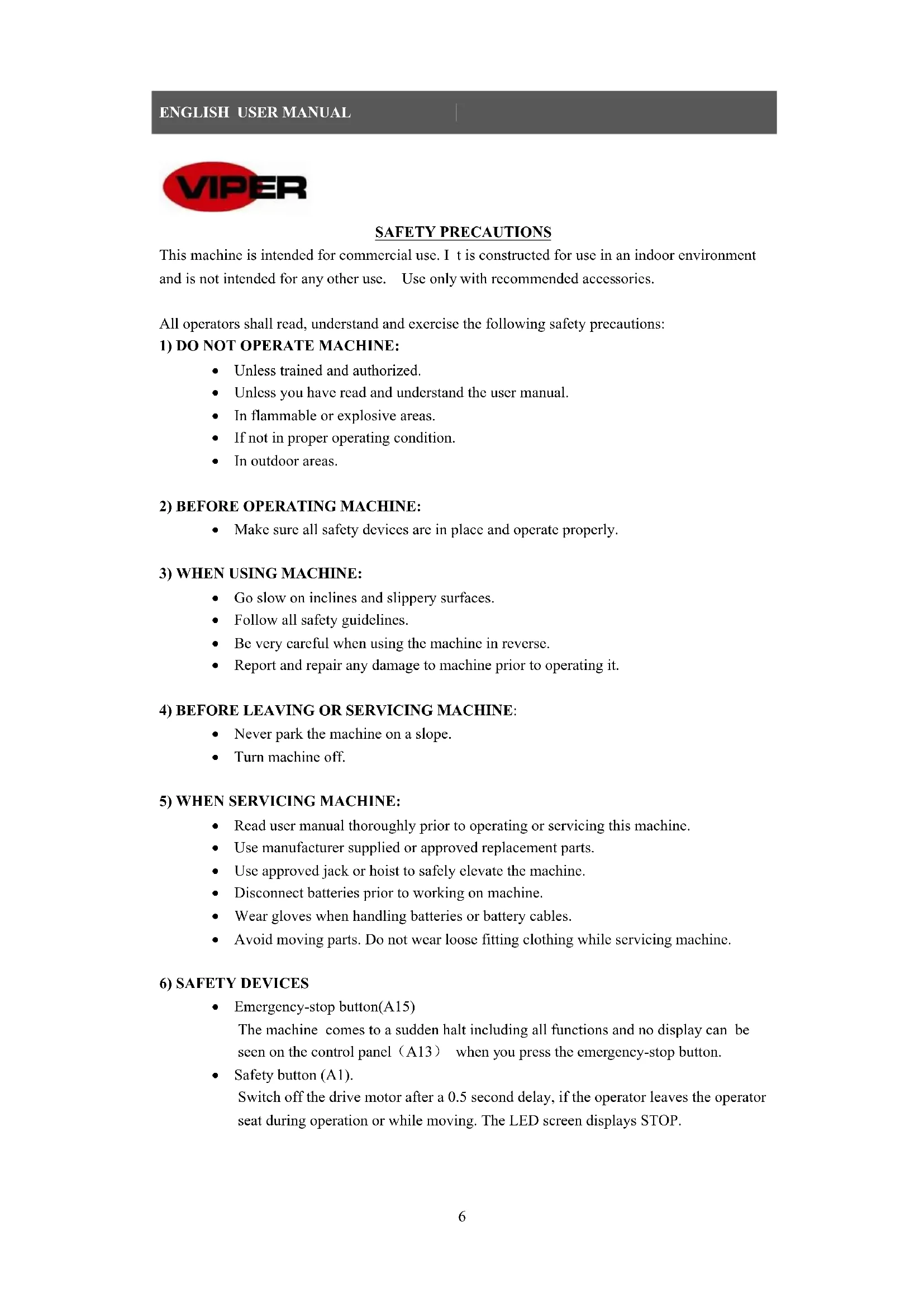
SAFETY PRECAUTIONS
This machine is intended for commercial use. I t is constructed for use in an indoor environment and is not intended for any other use. Use only with recommended accessories.
All operators shall read, understand and exercise the following safety precautions:
1) DO NOT OPERATE MACHINE:
• Unless trained and authorized.
• Unless you have read and understand the user manual.
• In flammable or explosive areas.
• If not in proper operating condition.
• In outdoor areas.
• Make sure all safety devices are in place and operate properly.
3) WHEN USING MACHINE:
- Go slow on inclines and slippery surfaces.
• Follow all safety guidelines. - Be very careful when using the machine in reverse.
• Report and repair any damage to machine prior to operating it.
4) BEFORE LEAVING OR SERVICING MACHINE:
• Never park the machine on a slope.
- Turn machine off.
5) WHEN SERVICING MACHINE:
- Read user manual thoroughly prior to operating or servicing this machine.
- Use manufacturer supplied or approved replacement parts.
• Use approved jack or hoist to safely elevate the machine. - Disconnect batteries prior to working on machine.
- Wear gloves when handling batteries or battery cables.
- Avoid moving parts. Do not wear loose fitting clothing while servicing machine.
6) SAFETY DEVICES
• Emergency-stop button(A15)
The machine comes to a sudden halt including all functions and no display can be seen on the control panel (A13) when you press the emergency-stop button.
• Safety button (A1).
Switch off the drive motor after a 0.5 second delay, if the operator leaves the operator seat during operation or while moving. The LED screen displays STOP.

Batteries emit hydrogen. Explosion or fire can result from hydrogen. Keep sparks and open flames away! It is recommended to push the button (C2) to turn recovery tank open before charging.

Flammable materials can cause an explosion or fire. Do not use flammable materials in tanks.

Flammable materials or reactive metals can cause an explosion or fire. Do not pick up by hand.

WARNING It indicates a potential risk of injury or dangerous situation with risk of death for the operator.

NOTED It indicates a remark related to important reminding or useful functions.
MACHINE SET UP & INSTALLATION
UNPACKING MACHINE
Be sure and check packing carton for any damage. Report immediately any damage to carrier. Check contents of package to ensure that the following items are included:
- Machine
- Squeegee assembly
- Brush assembly (x2)
- User manual
- Battery charger (If equipped)
- Batteries (x4) (If equipped)
- Connecting wire for battery and charger (If equipped)
- Warning lamp (If equipped)
- Bumper bracket (If equipped)
BATTERY CONNECTIONS
- Turn off the key switch (E5).
- Turn the seat (A1) open, push board (C2) and turn recovery tank (A3) open. If machine does not include batteries. Fit batteries suitable to your requirements.
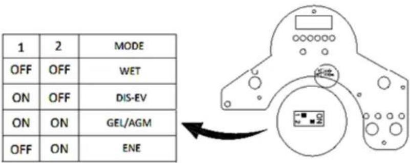
After selecting batteries, please choose WET or GEL mode with toggle switch on the back of PCB, as shown in the figure below.
-
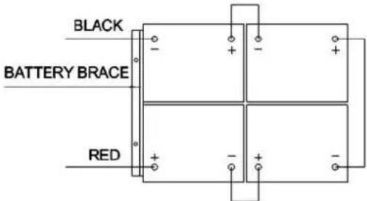
Carefully place the four batteries into the compartment as shown in figure below. Place the battery brace at the front of the four batteries.
-
Connect battery cables to posts in numbered order as shown in the figure below.
-
Apply a coat or protective spray on the cable connections to prevent battery corrosion.
-
Cover recovery tank and seat.

Make sure the recovery tank is empty when turn it.

Do not drop batteries into compartment. Do not put metal on the batteries.

Never connect + to +, or - to - , never connect + to - with single battery, when disassembling or installing the batteries.
MACHINE SET UP
- Sweep or dust mop the surface to be cleaned.
- Check battery meter to make sure batteries are fully charged. (see BATTERY CHARGING)
- Check that brush / pad is properly installed.
- Check that squeegee is properly installed.
- Check the speed driver (A9) is work normally.
- Make sure the recovery tank is empty. If not, drain it.
-
Make sure solution tank water indicator (E10) is not on. If on, fill water in solution tank (A4).
-
Check that the water valve (D2) is not indicated "0".
INSTALLING PAD DRIVER OR BRUSH
- Ensure that the machine is turned off (E5).
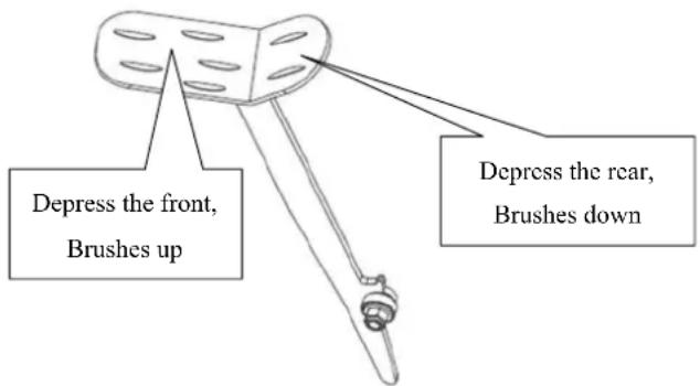
- Raise the brush head (A7) off the floor by trampling the front of foot pedal (A10) on the left of machine.
- Put brushes (A8) below both driver motor hub.
- Lower the brush head (A7) assembly by trampling the rear of foot pedal (A10). And sitting on the machine to start brush switch (E3). Lightly depress driver pedal (C6), then brushes automatic installed. If installation cannot be performed successfully in one shot, turn off brush switch (E3) and reset the suit position to install brushes.
- Adjusting the nut (A6) to properly place for work.

Never work without the brusher/pad perfectly installed.

When cleaning or replacing the brushes, you should raise the brush head and rotate the reverse direction to “working” direction quickly. The two brushes are reverse in direction.
INSTALLING AND ADJUSTING THE SQUEEGEE
- Ensure that the machine is turned off (E5).
- Turn the squeegee 1 ift lever (C5) to put down the squeegee bracket (A5) on floor.
- Loosen the two knobs (B2) on the squeegee and slide the squeegee into the slots in the back of the squeegee bracket.
- Tighten the knobs(B2) securely.
- Secure the vacuum hose (B3) on the pick-up tube of the squeegee.
- Adjusting the nut (B1) to properly place for suction.
FILLING THE SOLUTION TANK
- It can be filled in water use a hose under the seat (C4).
- Do not overfill the solution tank. Leave at least two inch from the opening of tank.
- Water temperature should not exceed 40^ C.

Use only low-foam and non-flammable det ergents suitable for ride-on scrubber applications.

Each time when you need to fill the solution tank, always empty and clean the recovery tank by removing the drain hose plug(C1). After each use, unscrew the drain cap (D1) to drain solution tank.
CHECKING THE SPEED DRIVER
- Sit on seat (A1) of the machine.
- Turn on the key switch (E5).
- Lightly depress the driver pedal (C6) to move and release it checking the machine forward or stop.
- For more security, you need to press the Emergency-stop button (A15) to make machine sudden halt to check the button is work, when you use the machine for the first time. Release it by turning.
- If the drive motor error indicator (E4) is on, you must pay more attention. see ERROR INFORMATION

The gradient in the direction of travel should not exceed (10) %.

The brake of drive motor is active when the machine is running normally, that is the brake bracket is close to motor main body. When machine is on package \un-package or machine error and some special situations, brake bracket will pull out, and use washer to choke, so the machine can move by hand pushing.
MACHINE OPERATION

Do not operate machine unless you have professional training. You have read and understand this manual before operate machine.
- You should sit on the seat of the machine when you operate it.
- Lower squeegee assembly to the floor.

Make sure to raise the squeegee before the machine is moving backward, or machine stops and LED screen displays ERR-01.
- Lower the brush head to the floor.

You'd better to turn off the brush motor button before raising the brush to prevent water throw out. You'd better to raise the brush head before the machine is reverse. Don't make brushes work in a same place for a long time to damage the floor.
- Turn on the key switch.(E5)
- Turn on the brush motor switch.(E3)
- Depress the driver pedal slowly (C6) and turn steering wheel (A14) to forward. The speed can be controlled by a dial (E6), turning left decreases speed, and turning right increases speed. And to reverse, you can press the switch (E7).
- Adjust amount of solution flow by pressing the solution/water adjustment button. (D5)
- As long as you turn on the key switch (E5), you can charge the cell-phone through the USB charging interface (A11).
- You may press the horn (E9) for alert in case of encountering unexpected crowds or heavy crowds.

When battery indicator is red and flashing, do not continue to operate the machine; otherwise, this will cause harm to the batteries or machine. Recharge batteries.

Regularly view the clear tube (C7). If tank runs empty, turn off the brush switch, solution switch and raise the brush head. Keep the squeegee down and continue to vacuum until all dirty water is picked up.

Regularly view the filter (D3) and clean it by unscrewing the transparent cover.

If the squeegee assembly leaves streaks on the floor, raise the squeegee off the floor and wipe the blades down with a damp cloth.

Do not use your fingers to wipe or remove debris from the blades, as injury may occur.

When normal circumstances, the brake on the drive motor is applied. When all of the safety system are “go”, and the drive pedal is depressed, the brake will release and the machine will move.
In special circumstances (dead batteries, no batteries or major malfunction), the brake can be manually released so the machine can be pushed. Pull the brake bracket put (it will only move about 1/4 inch) and use an allen wrench or screw driver as a wedge to hold the bracket out.
BATTERY CHARGING

Please use approved chargers to charge the batteries, while the machine is not equipped with on-board battery charger.

For good machine performance, always keep batteries charged at all times. Do not let them be in an over-discharged condition.

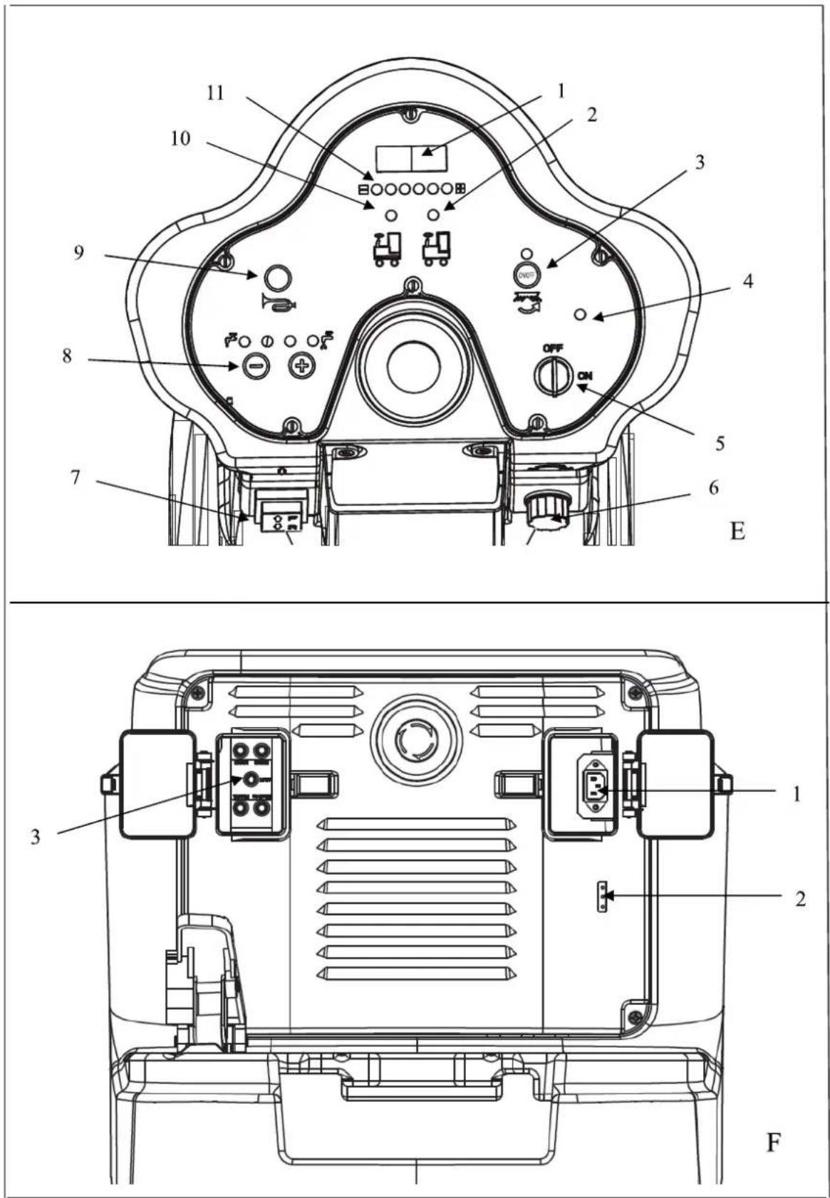
When charging the machine, make sure the transparent cover is open. Charge the batteries when the red indicator (E11) on.
ENGLISH USER MANUAL
- Charge the machine in a well-ventilated area.
- Turn machine off (E5).
- Plug approved charger into grounded wall outlet. Open transparent cover, and then connect the charging cable to the machine socket (F1).
- The charger will automatically begin to charge the batteries.
- Check that the battery charging is complete. Charging indicator (F2) is green.
- Upon completion of charging, first unplug the charger from the wall outlet, and then disconnect the charger from the machine.
- Storage the charging cable in the below chair (C3).

Check battery connections for wear and loose terminals. Replace if necessary.

When charging the machine, please do not use machine.
Battery Charging Curve Set Up (SPE)

Do not set charger unless you have professional training
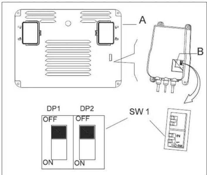
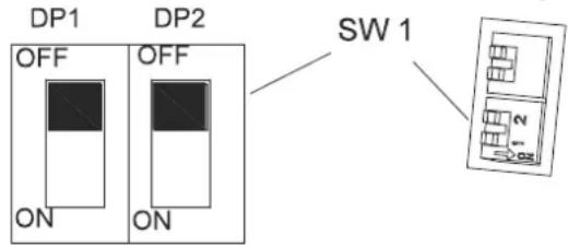
- Turn off the machine and disassemble the control cover (A) from the machine. Then pry open the label on the charger cover (B). you will find the 2 sets of dipswitches (SW1 and SW2) in the charger.
- Only the set of dip switch SW1 (the one on the left side) has effect on charging curve selection according to the table below. (SW2: OFF)
Battery mode setting up method of the charger.
Do not set charger unless you have professional training.
DIPSWITCH: SW1 (ONLY FOR)
USER MANUAL ENGLISH
| DP1 DP2 CHARGING CURVE | ||
| ON OFF IUIa-ACD for Lead-acid (Wet) batteries | ||
| OFF OFF IUIa-GEL for Gel batteries of Exide-Sonnenschein | ||
| OFF ON IUU0-GEL for HAZE Gel and AGM batteries of other manufacturers | ||
| ON ON IUIUa-AGM for Discover AGM batteries |
Battery Charging Curve Set Up (Powerfirst)

Do not set charger unless you have professional training
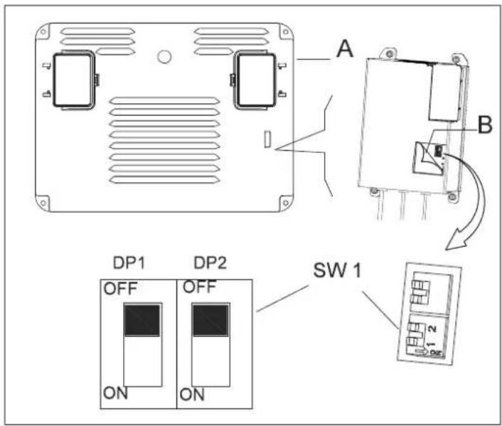
- Turn off the machine and disassemble the control cover (A) from the machine. Then pry open the label on the charger cover (B). you will find the 2 sets of dipswitches (SW1 and SW2) in the charger.
- Only the set of dip switch SW1 (the one on the left side) has effect on charging curve selection according to the table below. (SW2: OFF)
Battery mode setting up method of the charger.
Do not set charger unless you have professional training.
DIPSWITCH: SW1 (ONLY FOR)
| DP1 DP2 CHARGING CURVE | |
| ON OFF | IUIa-Acd for Flooded/Wet traction batteries |
| OFF OFF | IUIa for Gel batteries of Exide-Sonnenschein |
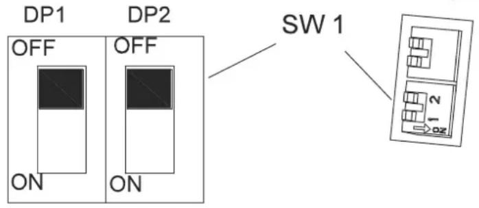
| OFF ON | IUUa for Fullriver AGM batteries (default) |
| ON ON IUIa for Discover AGM batteries | |
MACHINE STORAGE
If the machine is not going to be used for more than 30 days, please proceed with the following actions:
- Perform the "After each use" maintenance procedures. (See Maintenance section).
- Raise brush and squeegee.
- Store machine in a clean, dry and no slope place. If storage in an area that may reach freezing temperatures, be sure to drain all fluids from the machine prior to storage. Any damage caused by freezing will void the warranty.
MAINTENANCE

Maintenance procedures must be performed with the machine turned off and battery charger cable disconnected.

All maintenance procedures must be performed by qualified personnel, or by authorized Service Center. This Manual describes only the most common maintenance. For additional maintenance procedures, contact your local Service Center.
SCHEDULED MAINTENANCE TABLE
| Procedure | After each use | Weekly | Every six mouths | Annually |
| Battery charging | ||||
| Clean Squeegee | ||||
| Clean Brush/Pad | ||||
| Clean Tank and vacuum grid with float, cover gasket check | ||||
| Squeegee blade check and replacement | ||||
| Recovery filter cleaning | ||||
| Clean solution pipe filter | ||||
| Screw and nut tightening check | (1) | |||
| lubricate rotary parts (1) | ||||
| Brush/Pad-holder motor carbon brush check or replacement | (2) | |||
| Vacuum system motor carbon brush check or replacement | (2) | |||
| Drive motor check or replacement (2) |
(1) And after the first 8 working hours.
(2) This maintenance procedure must be performed by an authorized Service Center.
SQUEEGEE CLEAN AND BLADE REPLACEMENT

For optimal performance, the squeegee blades must be clean, dry and undamaged. If damaged, replace it.
- Unscrew the knob (B2) to remove squeegee.
- Unscrew the left and right knob to relax the front clamp, replace the front blade.
- Disengage the retainers (B4) and remove the rear clamp, replace the rear blade.
- Install the blades in the reverse order to removal.
- Install the squeegee to screw the knob (B2).
LED SCREEN DISPLAY INFORMATIONS
STOP Machine doesn't move and brush doesn't work, vacuum motor can work
00012.3 Machine add up driver time is 12.3 hours
L0-18 Batteries voltage is lower 18V
U-25.5 Batteries voltage is 25.5V
ERR-01 Squeegee pulls down before machine reverse
DRIVE MOTOR ERROR INDICATOR INFORMATION
LED FLASH CODES EXAMPLE, 📄 📄 means LED flash 2 times, after several seconds LED flash 4 times.
LED is always light in normal work.
| LED FLASH CODES DESCRIPTION | ||
| 1.1 | Overheating >92°,motor overload | |
| 1.2 | Accelerator malfunction | |
| 1.3 | Speed limiter potentiometer malfunction | |
| 1.4 | Under-voltage malfunction | |
| 1.5 | Overvoltage malfunction | |
| 2.1 | Principal contactor actuator opening failure | |
| 2.2 | Principal contactor bond | |
| 2.3 | Principal contactor malfunction, faulty electrical brake coil | |
| 2.4 | Principal contactor actuator closing failure | |
| 3.1 | Accelerator potentiometer malfunction | |
| 3.2 | Brake activation malfunction | |
| 3.4 | Brake deactivation malfunction | |
| 3.5 | HPD malfunction(incorrect regulation of accelerator potentiometer) | |
| 4.1 | Motor short circuit | |
| 4.2 | Incorrect motor voltage/short circuit in motor | |
| 4.3 | EEPROM malfunction | |
| 4.4 | Short circuit in motor/EEPROM error | |
Parameter
| Model AS710R AS850R | ||
| Machine length/width/height | 1580*760*1230 1580*890*1230 | |
| Solution tank capacity | 120L 120L | |
| Recovery tank capacity | 120L 120L | |
| Rear wheels diameter | 300MM 300MM | |
| Brush motor power | 2x300W 2x300W | |
| Vacuum motor power | 500W 500W | |
| Drive motor power | 500W 500W | |
| Max. driver speed | 6km/h 6km/h | |
| Sound level | 69dB(A) 69dB(A) | |
| Batteries length/width/height | 241*168*300 | 241*168*300 |
| Batteries spec | 4x245AH(20hours) | 4x245AH(20hours) |
| Vaccum capacity | 1800mm H2O 1800mm H2O | |
| Cleaning productivity | 4413sq.m/h 5130sq.m/h | |
| Squegee width | 940MM 1060MM | |
| Brush diameter | 2x355MM | 2x406MM |
| Brush rpm | 204rpm/min | 204rpm/min |
| Charger | 24V 25A | 24V 25A |
| Machine weight | 225KG | 230KG |
| Machine weight(gross) | 400KG | 440KG |
| Carton spec | 1730*810*1410 | 1730*900*1410 |
| USB charger spec | 5V, 0.8A | 5V, 0.8A |
| Gradient | 10% | 10% |
| Brush deck width | 740mm | 850mm |
| Water Flow | ||
| Indication LEDs | Solenoid Valve | Aerage Water Flow (L/min) |
| 1 LED ON 2S ON 4S OFF 1.4 | ||
| 2 LEDs ON 3S ON 3S OFF 2.1 | ||
| 3 LEDs ON 4S ON 2S OFF 2.8 | ||
| 4 LEDs ON ON 4.2 | ||
TROUBLESHOOTING
| Trouble Possible Cause Remedy | ||
| The machine does not work, LED screen (E1) does not turns on | The battery connector is disconnected Connect. | |
| The batteries are completely discharged Charge the batteries | ||
| The machine does not work, indicator light (E11) is red | The batteries are discharged Charge the batteries | |
| The machine does not forward or back | The PCB or key board is broken Change the PCB or key board | |
| Emergency-stop button (A15) does not release | Turn and release | |
| Seat limit switch is not activated. Sit on the seat of machine | ||
| Squeegee has not lifted in reverse, LED screen (E1) display ERR-01 | Before reversing, lift the squeegee | |
| Brush motor does not work, indicator light does not turns on | The PCB or key board is broken Change the PCB or key board | |
| The deck motor is overloaded | Use less aggressive brushes suitable for the floor to be cleaned, reset the breaker | |
| There are foreign materials preventing the brush from rotating | Clean the brush hub | |
| Drive motor does not work | Error indicator (E4) is lit Refer to ERROR INFORMATION | |
| Drive motor is overloaded | Check the drive motor, reset the breaker | |
| Vacuum system motor does not work | The recovery tank is full, light (E2) is red Empty the recovery tank | |
| The vacuum motor is overloaded | Check the vacuum motor, reset the breaker | |
| The PCB or key board is broken Change the PCB or key board | ||
| The dirty water vacuuming is insufficient | The recovery tank is full, light (E2) is red Empty the recovery tank | |
| The hose is disconnected from the squeegee | Re-connect | |
| Vacuum assembly is clogged Clean or check | ||
| The squeegee is dirty, or the squeegee blades are worn or damaged | Clean and check the squeegee | |
| The tank cover (A2) is not properly closed, or the gasket is damaged | Close the cover properly or replace the gasket | |
| The solution flow is insufficient | The solution filter (D3) is dirty, Clean the filter | |
| The solution is empty, light (E10) is red Full in water | ||
| Water switch (D2) indicate “0” Open the water switch | ||
| The solution is dirty Clean the solution | ||
| The squeegee leaves marks on the floor | There is debris under the squeegee blades | Remove the debris |
| The squeegee blades are worn, chipped or torn | Replace the blades | |
| Machine cannot brake Do not start the drive motor brake Brake bracket is choked | ||

SICHERHEITSHINWEISE
LED-SCHERM DISPLAY INFORMATIE
Interruptor DIP: SW1 (UNICAMENTE PARA)
Interruptor DIP: SW1 (UNICAMENTE PARA)
Interruptor DIP: SW1 (SÓ PARA)
| DP1 DP2 CURVA DE CARREGAMENTO | ||
| ON OFF IUIa-ACD para baterias de ácido-chumbo (Molhado) | ||
| OFF OFF IUIa-GEL para baterias de Gel de Exide-Sonnenschein | ||
| OFF ON IUU0-GEL para baterias HAZE Gel e AGM de outros fabricantes | ||
| ON ON IUIUa-AGM para baterias Discover AGM |
Interruptor DIP: SW1 (SÓ PARA)

| COD LICĂRIRE LEDURI | DESCRIERE | |
| 1.1 | ☐ ☐ | Supraîncălzire >92°,motor în suprasarcină |
| 1.2 | ☐ ☐☐ Disfuncție accelerator | |
| 1.3 | ☐ ☐☐☐ Disfuncție potențiometru limitator de viteză | |
| 1.4 | ☐ ☐☐☐☐ Disfuncție voltaj prea mic | |
| 1.5 | ☐ ☐☐☐☐☐ Disfuncție supra-voltaj | |
| 2.1 | ☐☐☐ Servo-contactorul principal nu se deschide | |
| 2.2 | ☐☐☐☐ Legătură contactor principal | |
| 2.3 | ☐☐☐☐☐ Disfuncție contactor principal, bobina electrica de la frână stricată | |
| 2.4 | ☐☐☐☐☐☐ Servo-contactorul principal nu se închide | |
| 3.1 | ☐☐☐☐ Disfuncție potențiometru accelerator | |
| 3.2 | ☐☐☐☐☐ Disfuncție activare frâne | |
| 3.4 | ☐☐☐☐☐☐ Disfuncție dezactivare frâne | |
| 3.5 | ☐☐☐☐☐☐☐☐☐☐☐☐☐☐☐☐☐☐☐☐☐☐☐☐☐☐☐☐☐☐☐☐☐☐☐☐☐☐☐☐☐☐☐☐☐☐☐☐☐☐☐☐☐☐☐☐☐☐☐☐☐☐☐☐☐☐☐☐☐☐☐☐☐☐☐☐☐☐☐☐☐☐☐☐☐☐☐☐☐☐☐☐☐☐☐☐☐☐☐☐ ☐☐☐☐☐☐☐☐☐☐☐☐☐☐☐☐☐☐☐☐☐☐☐☐☐☐☐☐☐☐☐☐☐☐☐☐☐☐☐☐☐☐☐☐☐☐☐☐☐☐☐☐☐☐☐☐☐☐☐☐☐☐☐☐☐☐☐☐☐☐☐☐☐☐☐☐☐☐☐☐☐☐☐☐☐☐☐☐☐☐☐☐☐☐☐☐☐☐☐☐☑☐☐☐☐☐☐☐☐☐☐☐☐☐☐☐☐☐☐☐☐☐☐☐☐☐☐☐☐☐☐☐☐☐☐☐☐☐☐☐☐☐☐☐☐☐☐☐☐☐☐☐☐☐☐☐☐☐☐☐☐☐☐☐☐☐☐☐☐☐☐☐☐☐☐☐☐☐☐☐☐☐☐☐☐☐☐☐☐☐☐☐☐☐☐☐☐☐☐☐☒☐☐☐☐☐☐☐☐☐☐☐☐☐☐☐☐☐☐☐☐☐☐☐☐☐☐☐☐☐☐☐☐☐☐☐☐☐☐☐☐☐☐☐☐☐☐☐☐☐☐☐☐☐☐☐☐☐☐☐☐☐☐☐☐☐☐☐☐☐☐☐☐☐☐☐☐☐☐☐☐☐☐☐☐☐☐☐☐☐☐☐☐☐☐☐☐☐☐☐□☐☐☐☐☐☐☐☐☐☐☐☐☐☐☐☐☐☐☐☐☐☐☐☐☐☐☐☐☐☐☐☐☐☐☐☐☐☐☐☐☐☐☐☐☐☐☐☐☐☐☐☐☐☐☐☐☐☐☐☐☐☐☐☐☐☐☐☐☐☐☐☐☐☐☐☐☐☐☐☐☐☐☐☐☐☐☐☐☐☐☐☐☐☐☐☐☐☐☐○☐☐☐☐☐☐☐☐☐☐☐☐☐☐☐☐☐☐☐☐☐☐☐☐☐☐☐☐☐☐☐☐☐☐☐☐☐☐☐☐☐☐☐☐☐☐☐☐☐☐☐☐☐☐☐☐☐☐☐☐☐☐☐☐☐☐☐☐☐☐☐☐☐☐☐☐☐☐☐☐☐☐☐☐☐☐☐☐☐☐☐☐☐☐☐☐☐☐☐ | |
| 4.1 | ☐☐☐☐☐ ☐ Scurtcircuit la motor | |
| 4.2 | ☐☐☐☐☐ ☐ Voltaj incorrect la motor/ scurtcircuit la motor | |
| 4.3 | ☐☐☐☐☐ ☐ Disfuncție EEPROM | |
| 4.4 | ☐☐☐☐☐ ☐ Scurtcircuit la motor/croare EEPROM | |
Parametru
ESITOIMINNAN TARKASTUKSET
DIP-LÜLITI:SW1 (AINULT)
| DP1 DP2 LAADIMISKÖVER | ||
| SEES | VÄLJAS | IUIa-Acd üleujutatud/märg-veoakude jaoks |
| VÄLJAS | VÄLJAS | IUIa Exide-Sonnenscheini geelakude jaoks |
| VÄLJAS | SEES | IUUa Fullriveri AGM-akude jaoks (vaikimisi) |
| SEES | SEES | IUIa Discoveri AGM-akude jaoks |
MASINA HOIUSTAMINE
PLĀNOTĀS APKOPES TABULA
Company information:
www.vipercleaning.eu
info-eu@vipercleaning.com

- TABLE OF CONTENTS
- SAFETY PRECAUTIONS
- MACHINE SET UP & INSTALLATION
- UNPACKING MACHINE
- BATTERY CONNECTIONS
- MACHINE SET UP
- INSTALLING PAD DRIVER OR BRUSH
- INSTALLING AND ADJUSTING THE SQUEEGEE
- FILLING THE SOLUTION TANK
- CHECKING THE SPEED DRIVER
- MACHINE OPERATION
- BATTERY CHARGING
- ENGLISH USER MANUAL
- Battery Charging Curve Set Up (SPE)
- Do not set charger unless you have professional training
- USER MANUAL ENGLISH
- Battery Charging Curve Set Up (Powerfirst)
- MACHINE STORAGE
- MAINTENANCE
- SQUEEGEE CLEAN AND BLADE REPLACEMENT
- LED SCREEN DISPLAY INFORMATIONS
- DRIVE MOTOR ERROR INDICATOR INFORMATION
- SICHERHEITSHINWEISE
- LED-SCHERM DISPLAY INFORMATIE
- ESITOIMINNAN TARKASTUKSET
- MASINA HOIUSTAMINE
Brand : NILFISK
Model : Viper AS710
Category : Sweeper