
SW5500 - Sweeper NILFISK - Free user manual and instructions
Find the device manual for free SW5500 NILFISK in PDF.

| Product type | Ride-on sweeper |
| Brand | Nilfisk |
| Model | SW5500 |
| Available versions | Diesel (SW5500 D) and LPG (SW5500 GPL / FLOORTEC R 985 GPL) |
| Sweeping width (1 side brush) | 1,175 mm |
| Sweeping width (2 side brushes) | 1,500 mm |
| Main brush dimensions | 850 x 360 mm |
| Side brush diameter | 500 mm |
| Waste container - capacity | 150 liters |
| Waste container - max lift weight | 240 kg |
| Waste container - max lift height | 1,650 mm |
| Dust filter - surface area | 7 m² |
| Dust filter - filtration efficiency | 77 % @ 0.8 μm |
| Filter cleaning | Electric shaker |
| Engine power (Diesel version) | 4.1 kW (5.5 hp) at 3,000 rpm |
| Engine power (LPG version) | 5.7 kW (7.6 hp) at 3,000 rpm |
| Diesel engine | Yanmar L70N |
| LPG engine | Honda iGX 270 |
| Fuel type | Diesel or LPG depending on version |
| Fuel tank capacity (Diesel) | 7 liters |
| Fuel tank capacity (LPG) | 15 kg |
| Engine oil (Diesel) | SAE 15W40 |
| Engine oil (LPG) | SAE 10W30 |
| Traction | Electric on front wheel, 1,200 W |
| Maximum forward speed | 10 km/h |
| Maximum reverse speed | 4.5 km/h |
| Maximum operating grade | 20% |
| Dimensions (L x W x H) machine body | 1,875 x 1,200 x 1,564 mm |
| Empty weight (Diesel) | 757 kg |
| Empty weight (LPG) | 764 kg |
| Operator sound pressure level (Diesel) | 85 dB(A) ± 3 dB(A) |
| Operator sound pressure level (LPG) | 79 dB(A) ± 3 dB(A) |
| Protection rating IP | X3 |
| Water tank capacity DustGuard system (optional) | 32 liters |
| Safety system | Emergency stop button, seat microswitch, anti-skid, tilt sensor, container position sensor, container safety valve |
Frequently Asked Questions - SW5500 NILFISK
User questions about SW5500 NILFISK
0 question about this device. Answer the ones you know or ask your own.
Ask a new question about this device
Download the instructions for your Sweeper in PDF format for free! Find your manual SW5500 - NILFISK and take your electronic device back in hand. On this page are published all the documents necessary for the use of your device. SW5500 by NILFISK.
USER MANUAL SW5500 NILFISK
SW5500, FLOORTEC R 985
Instructions for use
Bedienungshandbuch
Instructions for use
Gebruiksaanwijzing

03/2016 Revised 04/2018
(B)
1466472000

Deutsch
Français
English
Nederlands


Model No.:
9084411010, 9084412010, 9084414010
Сертификат за съответствие Osvědčení o shodě Konformitätserklärung Overensstemmelsescertifikat Declaración de conformidad Vastavussertifikaat Déclaration de conformité Yhdenmukaisuustodistus Conformity certificate
Πιστοποιητικό συμμόρφωσης Megfelelősségi nyilatkozat Potvrda sukladnosti Dichiarazione di conformità Atitikties deklaracija Atbilstības deklarācija Konformitetssertifisering Conformiteitsverklaring Declaração de conformidade
Deklaracja zgodności Certificat de conformitate Заявление о соответствии Överensstämmelsecertifikat Certifikát súladu Certifikat o ustreznosti Uyumluluk sertifikası
CE
Model / Model / Modell / Model / Modelo / Mudel / Modèle / Malli / Model / Movtélo / Modell / Model / Modello / Modello / Modelis / Modelis / Modell / Model / Modelo / Model / Model / Model / Model / Model / Model / Model :
SW5500 - FLOORTEC R 985
Típ / Typ / Typ / Type / Tipo / Tüüp / Type / Tyuppi / Type / Túpoç / Típus / Vrsta / Tipo / Tipas / Tips / Type / Type / Tipo / Typ / Típ / Típ / Typ / Typ / Tip / Tip :
SWEEPER
Сериен номер / Výrobní číslo / Seriennummer / Serienummer / Número de serie / Seerianumber / Numéro de série / Sarjanumero / Serial number / Šειριακός αριθμός / Sorozatszám / Serijski broj / Numero di serie / Serijos numeris / Sērijas numurs / Serienummer / Serienummer / Número de série / Numer seryjny / Număr de serie / Серийный номер / Serienummer / Výrobné číslo / Serijska številka / Seri Numarası :
Година на производство / Rok výroby / Baujahr / Fabrikationsár / Año de fabricación / Väljalaskeaasta / Année de fabrication / Valmistusvuosi / Year of construction / Έτος κατασκευής / Gyártási év / Godina izgradnje / Anno di costruzione / Pagaminimo metai / Izgatavošanas gads / Byggeår / Bauwjaar / Ano de fabrico / Rok produkcji / Anul fabricatiei / Год выпуска / Tillverkningsár / Rok výroby / Leto izdelave / Leto izdelave/Imal yili :

The undersigned certify that the above mentioned model is produced in accordance with the following directives and standards. The technical file is compiled by the manufacturer.

Authorized signatory: Sergio Coccapani, R&D Director
Date: Signature:

INHALTSVERZEICHNIS
EINLEITUNG......2
P100919


P100921
P100922
SCHALTPLAN LPG-VERSION
Legende
P100923
BETRIEB

ACHTUNG!
P100901
P100902
P100904
Abbildung 10
P100905
Abbildung 11
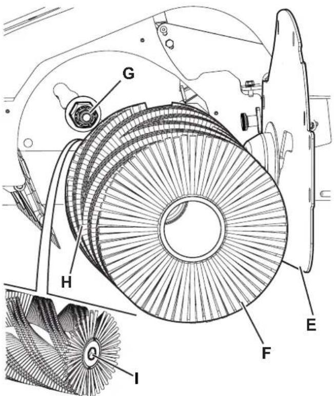
Abbildung 15
P100909
P100910
Abbildung 16
P100914

Abbildung 21
P100915
WASSERFILTER DER DUSTGUARD™-STAUBABSCHEIDUNGSANLAGE (OPTION) REINIGEN

ANMERKUNG
Abbildung 22
Abbildung 23
P100917
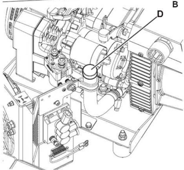
Abbildung 25
P100926
KONTROLLE/REINIGUNG DER ÖLFILTER DES MOTORS (DIESEL-Version)
Abbildung 26
P100927
Abbildung 28
P100929
8.
P100918
Abbildung 30
FEHLERSUCHE
CONSERVATION DU MANUEL....2
DÉCLARATION DE CONFORMITÉ 2
DONNÉES D'IDENTIFICATION 2
AUTRES MANUELS DE RÉFÉRENCE....3
PIÈCES DE RECHANGE ET ENTRETIEN 3
MODIFICATIONS ET AMÉLIORATIONS....3
CAPACITÉS OPÉRATIONNELLES....3
CONVENTIONS 3
DÉBALLAGE / LIVRAISON....3
SÉCURITÉ 3
SYMBOLES VISIBLES SUR LA MACHINE....4
SYMBOLES UTILISÉS DANS LE MANUEL....4
INSTRUCTIONS GÉNÉRALES 4
DESCRIPTION DE LA MACHINE 8
STRUCTURE DE LA MACHINE....8
TABLEAU DE BORD ET COMMANDES....11
ACCESSOIRES / OPTIONS....12
CARACTÉRISTIQUES TECHNIQUES 12
SCHÉMA ÉLECTRIQUE VERSION DIESEL....14
SCHÉMA ÉLECTRIQUE VERSION GPL 16
UTILISATION 18
CARBURANT....18
AVANT LA MISE EN MARCHE 19
MISE EN MARCHE ET ARRÊT DE LA MACHINE 19
FREIN DE STATIONNEMENT....20
MACHINE AU TRAVAIL 21
VIDANGE DU CONTENEUR DÉCHETS 22
APRÈS L'UTILISATION DE LA MACHINE 23
INACTIVITÉ PROLONGÉE DE LA MACHINE 23
ENTRETIEN 23
PLAN D'ENTRETIEN PROGRAMMÉ....23
PAGES-ÉCRAN DE SERVICE DE L'ÉCRAN MULTIFONCTION....25
CONTRÔLE ET RÉGLAGE DE LA HAUTEUR DU BALAI CENTRAL 27
REMPLACEMENT DU BALAI CENTRAL 28
CONTRÔLE ET RÉGLAGE DE LA HAUTEUR DES BALAIS LATÉRAUX....29
REMPLACEMENT DES BALAIS LATÉRAUX 30
NETTOYAGE ET CONTRÔLE DE L'INTÉGRITÉ DU FILTRE À POUSSIÈRE EN PANNEAU 31
CONTRÔLE DE LA HAUTEUR ET DU FONCTIONNEMENT DES VOLETS....32
NETTOYAGE DU FILTRE À EAU DU SYSTÈME D'ABATTAGE DES POUSSIÈRES DUSTGUARD™ (OPTIONNEL)....33
CONTRÔLE DU NIVEAU D'HUILE DU SYSTÈME HYDRAULIQUE....33
CONTRÔLE DU NIVEAU D'HUILE ET VIDANGE D'HUILE MOTEUR (version DIESEL) 34
CONTRÔLE DU NIVEAU D'HUILE ET VIDANGE D'HUILE MOTEUR (version GPL)....35
CONSERVATION DU MANUEL
DÉCLARATION DE CONFORMITÉ
STRUCTURE DE LA MACHINE
STRUCTURE DE LA MACHINE (suite)

P100919
STRUCTURE DE LA MACHINE (suite)


P100921
ACCESSOIRES / OPTIONS
P100922
SCHÉMA ÉLECTRIQUE VERSION GPL
Légende
P100901
Figure 7
P100902
Figure 8
P100903
Figure 9
REPLACEMENT DU BALAI CENTRAL

ATTENTION!
P100904
Figure 10

P100905
Figure 11
P100906
Figure 12

P100908
Figure 14
REEMPLACEMENT DES BALAIS LATÉRAUX

ATTENTION!
P100909
Figure 15
NETTOYAGE ET CONTRÔLE DE L'INTÉGRITÉ DU FILTRE À POUSSIÈRE EN PANNEAU
Figure 17
P100911
CONTRÔLE DE LA HAUTEUR ET DU FONCTIONNEMENT DES VOLETS
P100914
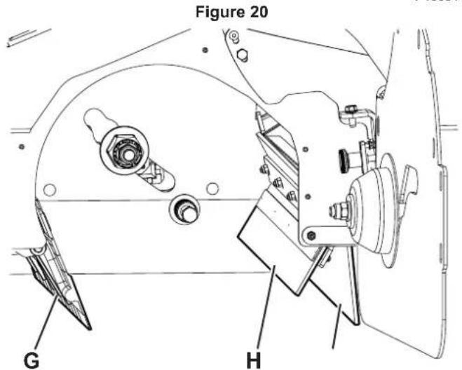
Figure 21
NETTOYAGE DU FILTRE À EAU DU SYSTÈME D'ABATTAGE DES POUSSIÈRES DUSTGUARD™ (OPTIONNEL)

REMARQUE
Figure 23
CONTRÔLE DU NIVEAU D'HUILE ET VIDANGE D'HUILE MOTEUR (version DIESEL)
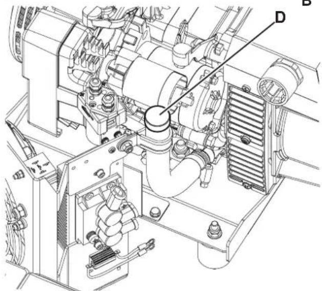
Figure 25
P100926
P100927
Figure 26
P100929
Figure 28
- P100918
Figure 30
DÉPISTAGE DES PANNES
MANUAL PURPOSE AND CONTENTS 2
TARGET 2
HOW TO KEEP THIS MANUAL....2
DECLARATION OF CONFORMITY 2
IDENTIFICATION DATA....2
OTHER REFERENCE MANUALS....3
SPARE PARTS AND MAINTENANCE....3
CHANGES AND IMPROVEMENTS 3
VISIBLE SYMBOLS ON THE MACHINE....4
SYMBOLS THAT APPEAR ON THIS MANUAL....4
GENERAL INSTRUCTIONS....4
MACHINE DESCRIPTION 8
MACHINE STRUCTURE 8
CONTROL PANEL....11
ACCESSORIES/OPTIONS....12
TECHNICAL DATA....12
DIESEL VERSION WIRING DIAGRAM....14
LPG VERSION WIRING DIAGRAM 16
USE 18
FUEL....18
BEFORE MACHINE START-UP 19
STARTING AND STOPPING THE MACHINE 19
PARKING BRAKE....20
AFTER USING THE MACHINE....23
MACHINE LONG INACTIVITY 23
MAINTENANCE 23
SCHEDULED MAINTENANCE TABLE 23
MULTIFUNCTION DISPLAY SERVICE SCREENS 25
MAIN BROOM HEIGHT CHECK AND ADJUSTMENT 27
MAIN BROOM REPLACEMENT 28
SIDE BROOM HEIGHT CHECK AND ADJUSTMENT 29
SIDE BROOM REPLACEMENT 30
PANEL DUST FILTER CLEANING AND INTEGRITY CHECK 31
SKIRT HEIGHT AND OPERATION CHECK 32
DUSTGUARD™ SYSTEM WATER FILTER CLEANING (OPTIONAL) 33
HYDRAULIC SYSTEM OIL LEVEL CHECK 33
ENGINE OIL LEVEL CHECK AND OIL REPLACEMENT (DIESEL version) 34
ENGINE OIL LEVEL CHECK AND OIL REPLACEMENT (LPG version)....35
ENGINE OIL FILTERS CHECK/CLEANING (DIESEL version) 36
ENGINE AIR FILTERS CHECK/CLEANING (DIESEL and LPG version) 37
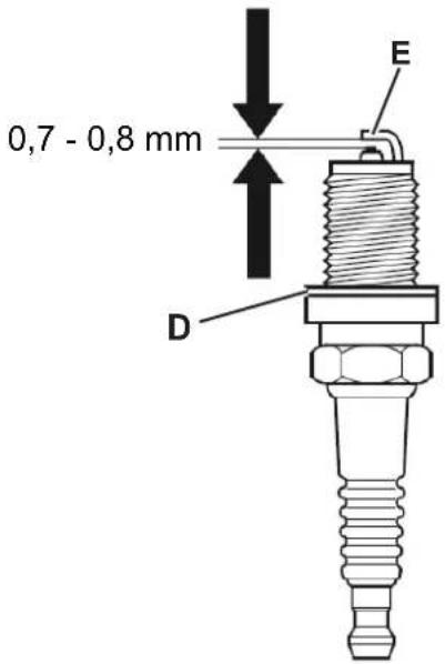
ENGINE SPARK PLUG CHECK/REPLACEMENT (LPG version)....38
BATTERY CHARGING (only for version with optional hybrid KIT installed)....39
FUSE CHECK/REPLACEMENT....40
SAFETY FUNCTIONS 40
EMERGENCY PUSH-BUTTON 40
DRIVER'S SEAT MICROSWITCH 40
ANTI-SKID SAFETY SYSTEM 40
MACHINE ANGLE SENSOR 40
HOPPER POSITION SENSOR 40
HOPPER SAFETY VALVE 40
TROUBLESHOOTING 41
SCRAPPING 42
INTRODUCTION

NOTE
The numbers in brackets refer to the components shown in Machine Description chapter.
MANUAL PURPOSE AND CONTENTS
The purpose of this Manual is to provide the operator with all necessary information to use the machine properly, in a safe and autonomous way. It contains information about technical data, safety, operation, storage, maintenance, spare parts and disposal. Before performing any procedure on the machine, the operators and qualified technicians must read this Manual carefully. Contact Nilfisk in case of doubts concerning the interpretation of the instructions and for any further information.
TARGET
This Manual is intended for operators and technicians qualified to perform the machine maintenance.
The operators must not perform procedures reserved for qualified technicians. Nilfisk will not be responsible for damages coming from failure to follow these instructions.
HOW TO KEEP THIS MANUAL
The Instructions for Use Manual must be kept near the machine, inside an adequate case, away from liquids and other substances that can cause damage to it.
DECLARATION OF CONFORMITY
The Declaration of Conformity, supplied with the machine, certifies the machine conformity with the law in force.

NOTE
Two copies of the original declaration of conformity are provided together with the machine documentation.
IDENTIFICATION DATA
The machine serial number and model name are marked on the plate (30).
Year of production (Date code: A18 means January 2018) and product code are marked on the same plate.
The engine model and serial number are shown on the engine plate (see the engine manual).
This information is useful when ordering machine and engine spare parts. Use the following table to write down the machine and engine identification data for any further reference.
MACHINE model ....
PRODUCT code ....
MACHINE serial number ....
ENGINE model
ENGINE serial number ....
OTHER REFERENCE MANUALS
– Spare Parts List (supplied with the machine)
– Engine Manual (Yanmar L70N) (DIESEL versions)
– Engine Manual (Honda iGX 200) (LPG versions)
– Service Manual (that can be consulted at Nilfisk Service Centers)
SPARE PARTS AND MAINTENANCE
All necessary operating, maintenance and repair procedures must be performed by qualified personnel or by Nilfisk Service Centers. Only original spare parts and accessories must be used.
Contact Nilfisk for service or to order spare parts and accessories, specifying the machine model, product code and serial number.
CHANGES AND IMPROVEMENTS
Nilfisk constantly improves its products and reserves the right to make changes and improvements at its discretion without being obliged to apply such benefits to the machines that were previously sold.
Any change and/or addition of accessory must be approved and performed by Nilfisk.
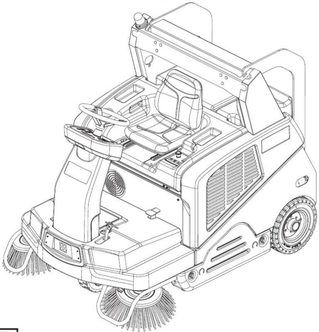
This sweeper has been designed to clean (by sweeping and vacuuming) smooth and solid floors, and to collect dust and light debris, in commercial and industrial environments, under safe operation conditions by a qualified operator.
CONVENTIONS
Forward, backward, front, rear, left or right are intended with reference to the operator's position, that is to say on the driver's seat (3).
UNPACKING/DELIVERY

CAUTION!
To unpack the machine, carefully follow the instructions on the packing.
Upon delivery carefully check that the machine and its packing have not been damaged during transportation. In case of visible damages, keep the packing and have it checked by the carrier that delivered it. Call the carrier immediately to fill in a damage claim. Check that the machine is equipped with the following features:
- Technical documents:
- Sweeper Instructions for Use Manual (this document)
• Engine Manual (Yanmar L70N) (DIESEL versions)
• Engine Manual (Honda iGX 200) (LPG versions) - Sweeper Spare Parts List
- No. 1 10 A fuse
SAFETY
The following symbols indicate potentially dangerous situations. Always read this information carefully and take all necessary precautions to safeguard people and property.
The operator's cooperation is essential in order to prevent injury. No accident prevention program is effective without the total cooperation of the person responsible for the machine operation. Most of the accidents that may occur in a factory, while working or moving around, are caused by failure to comply with the simplest rules for exercising prudence. A careful and prudent operator is the best guarantee against accidents and is essential for successful completion of any prevention program.
VISIBLE SYMBOLS ON THE MACHINE

WARNING!
Carefully read all the instructions before performing any operation on the machine.

WARNING!
Hot parts, danger of burns.

DANGER!
Internal combustion engine. Do not inhale exhaust gas fumes. Carbon monoxide (CO) can cause brain damage or death.

WARNING!
Moving parts.

WARNING!
Do not wash the machine with direct or pressurised water jets.

WARNING!
Moving parts. Danger of crushing.

WARNING!
Do not use the machine on slopes with a gradient exceeding the specifications.

WARNING!
Parts under voltage. Presence of corrosive fluids.
SYMBOLS THAT APPEAR ON THIS MANUAL

DANGER!
It indicates a dangerous situation with risk of death for the operator.

WARNING!
It indicates a potential risk of injury for people or damage to objects.

CAUTION!
It indicates a caution or a remark related to important or useful functions. Pay careful attention to the paragraphs marked by this symbol.

NOTE
It indicates a remark related to important or useful functions.

CONSULTATION
It indicates the necessity to refer to the Instructions for use Manual before performing any procedure.
GENERAL INSTRUCTIONS
Specific warnings and cautions to inform about potential damages to people and machine are shown below.

DANGER!


- Carbon monoxide (CO) can cause brain damage or death.
The internal combustion engine of this machine can emit carbon monoxide. - Do not inhale exhaust gas fumes.
- Only use indoors when adequate ventilation is provided, and with the help of an assistant who can monitor the operator's health.

DANGER!
Before performing any maintenance, repair, cleaning or replacement procedure disconnect the batteries, remove the ignition key and engage the parking brake.
- This machine must be used by properly trained operators only.
- Sharp turns must be made in safe conditions. Avoid abrupt turns, particularly on slopes, and turns with the hopper lifted.
- Do not lift the hopper when the machine is on a slope.
- Keep the batteries away from sparks, flames and incandescent material.
- Do not wear jewels when working near electrical components.
- Do not work under the lifted machine without supporting it with safety stands.
- When working under the open hood, ensure that it cannot be closed by accident.
- Do not operate the machine near toxic, dangerous, flammable and/or explosive powders, liquids or vapours: This machine is not suitable for collecting dangerous powders.
- Be careful: fuel is highly flammable.
- Do not smoke or bring naked flames in the area where the machine is refuelled or where the diesel fuel is stored.
- Refuel outdoors or in a well-ventilated area, with the engine off.
– Leave at least a space of 4 cm in the filler to allow the fuel to expand.
After refuelling, check that the fuel tank cap is firmly closed.
- If any fuel is spilled while refuelling, clean the tank area and allow the vapours to evaporate before starting the engine.
— Do not let fuel come into contact with the skin; do not breathe fuel vapours. Keep out of reach of children.
— Do not tilt the engine or the machine too much to avoid fuel spillage.
- When moving the machine, the fuel tank must not be full and the fuel valve must be closed.
- Do not lay any object on the engine.
- Stop the engine before performing any procedure on it. To avoid any incidental start, disconnect the spark plug cap or disconnect the battery negative terminal.
- See also the SAFETY RULES in the Engine Manual, which is to be considered an integral part of this Manual.
- Lead batteries (WET) are installed on this machine, do not tilt the machine more than 30° from its horizontal position to prevent the highly corrosive acid to leak out of the batteries. When the machine is to be tilted to perform maintenance procedures, remove the batteries.
(For LPG version). Do not use the machine in case of gas leaks. Disconnect the hose and replace the LPG tank. If the gas leak persists, disconnect the hose and contact the Nilfisk Service Center.

WARNING!
- Carefully read all the instructions before performing any maintenance/repair procedure.
- When working near the hydraulic system, always wear protective clothes and safety glasses.
- This machine is not intended for use by persons (including children) with reduced physical, sensory or mental capabilities, or lack of experience and knowledge, unless they have been given supervision or instruction concerning use of the machine by a person responsible for they safety.
Children should be supervised to ensure that they do not play with the machine.
- Close attention is necessary when used near children.
- Use only as shown in this Manual. Use only Nilfisk's recommended accessories.
- Check the machine carefully before each use, always check that all the components have been assembled before use. If the machine is not perfectly assembled it can cause damages to people and properties.
Take all necessary precautions to prevent hair, jewels and loose clothes from being caught by the machine moving parts.
- To avoid any unauthorised use of the machine, remove the ignition key.
- Do not leave the machine unattended without being sure that it cannot move independently.
- Do not use the machine on slopes with a gradient exceeding the specifications.
- Do not tilt the machine more than the angle indicated on the machine itself, in order to prevent instability.
- Use only brooms supplied with the machine or those specified in the Instructions for Use Manual. Using other brooms could reduce safety.

WARNING!
- This is a class A product. In a domestic environment this product may cause radio interference in which case the user may be required to take adequate measures.
— Before using the machine, close all doors and/or covers as shown in the Instructions for Use Manual. - Do not wash the machine with direct or pressurised water jets, or with corrosive substances.
– Use the machine only where a proper lighting is provided. - Working lights (optional) have to be used only to enhance visibility on the floor to be cleaned, but they do not authorize anyone to use the sweeper in dark environments.
While using this machine, take care not to cause damage to people or objects. - Do not bump into shelves or scaffoldings, especially where there is a risk of falling objects.
- Do not lean liquid containers on the machine, use the relevant can holder.
- The storage temperature must be between 0°C and +40°C .
- The machine working temperature must be between 0°C and +40°C .
- The humidity must be between 30% and 95% .
- Always protect the machine against the sun, rain and bad weather, both under operation and inactivity condition. Store the machine indoors, in a dry place. (if applicable) This machine must be used in dry conditions, it must not be used or kept outdoors in wet conditions.
- Do not use the machine as a means of transport, or for pushing/towing.
- The machine maximum capacity, operator's weight not included, is 240 kg (the weight of waste).
– In case of fire, use a powder fire extinguisher, not a water one.
- Adjust the operation speed to suit the floor conditions.
- Avoid sudden stops when the machine is going downhill. Avoid sharp turns. Drive at slow speed when going downhill.
- This machine cannot be used on roads or public streets.
- Do not tamper with the machine safety guards.
– Follow the routine maintenance procedures scrupulously.
- Do not allow any object to enter into the openings. Do not use the machine if the openings are clogged. Always keep the openings free from dust, hairs and any other foreign material which could reduce the air flow.
(Only for versions equipped with DustGuard™ system). Pay attention during machine transportation when temperature is below freezing point. The water in the tank or in the hoses could freeze and seriously damage the machine. - Do not remove or modify the plates affixed to the machine.
- When the machine is to be pushed for service reasons (lack of fuel, etc.), the speed must not exceed 4 km/h.
- In case of machine malfunctions, ensure that these are not due to lack of maintenance. If necessary, request assistance from the authorised personnel or from an authorised Service Center.
– If parts must be replaced, require ORIGINAL spare parts from an Authorised Dealer or Retailer. - To ensure machine proper and safe operation, the scheduled maintenance shown in the relevant chapter of this Manual, must be performed by the authorised personnel or by an authorised Service Center.
- The machine must be disposed of properly, because of the presence of toxic-harmful materials (batteries, oils, etc.), which are subject to standards that require disposal in special centres (see the Scrapping chapter).
While the engine is running, the silencer warms up; do not touch the silencer when it is hot to avoid burns or fires. - Running the engine with an insufficient quantity of oil can seriously damage the engine. Check the oil level with the engine off and the machine on a level surface.
– Never run the engine if the air filter is not installed, because the engine could be damaged.
– Technical service procedures on the engine must be performed by an authorised Dealer.
Only use original spare parts or parts of matching quality for the engine. Using spare parts of lower quality can seriously damage the engine.
– See also the SAFETY RULES in the Engine Manual, which is to be considered an integral part of this Manual.
Guide lines to bacteria control and other dangers coming from the presence of microbes in the DustGuard™ system (optional).

WARNING!
To prevent the operators and other people from developing infections caused by microbes and Legionella that may flourish in the dust guard system, take the following precautions:
If possible, fill the tank with cold water (< 20 °C).
- DO NOT use stagnant water to fill the tank.
– DO NOT use recycled water, undrinkable water or water that has been in contact with the soil.
- Adjust and turn the nozzles towards the floor only, from preventing possible inhaling.
- Do not store the machine outdoors or near sources of heat.
- Do not over-fill the tank. Fill the tank sufficiently so that it can be emptied by using the system.
– Empty the tank every 10 hours or once a week, according to the use.
- If the machine is not used for more than one week, empty the tank completely, and let it dry before storing it.
- If the tank cannot be cleaned regularly, consider using a biocide that can kill or exert a controlling effect on Legionella bacteria. Biocide must be chosen according to the local regulations and must be used according to the relevant instructions and cautions, to avoid that the personnel gets affected by dangerous chemical substances.
- If chemical products have to be used in the water tank, it is mandatory to apply the relevant information and caution labels of the product.
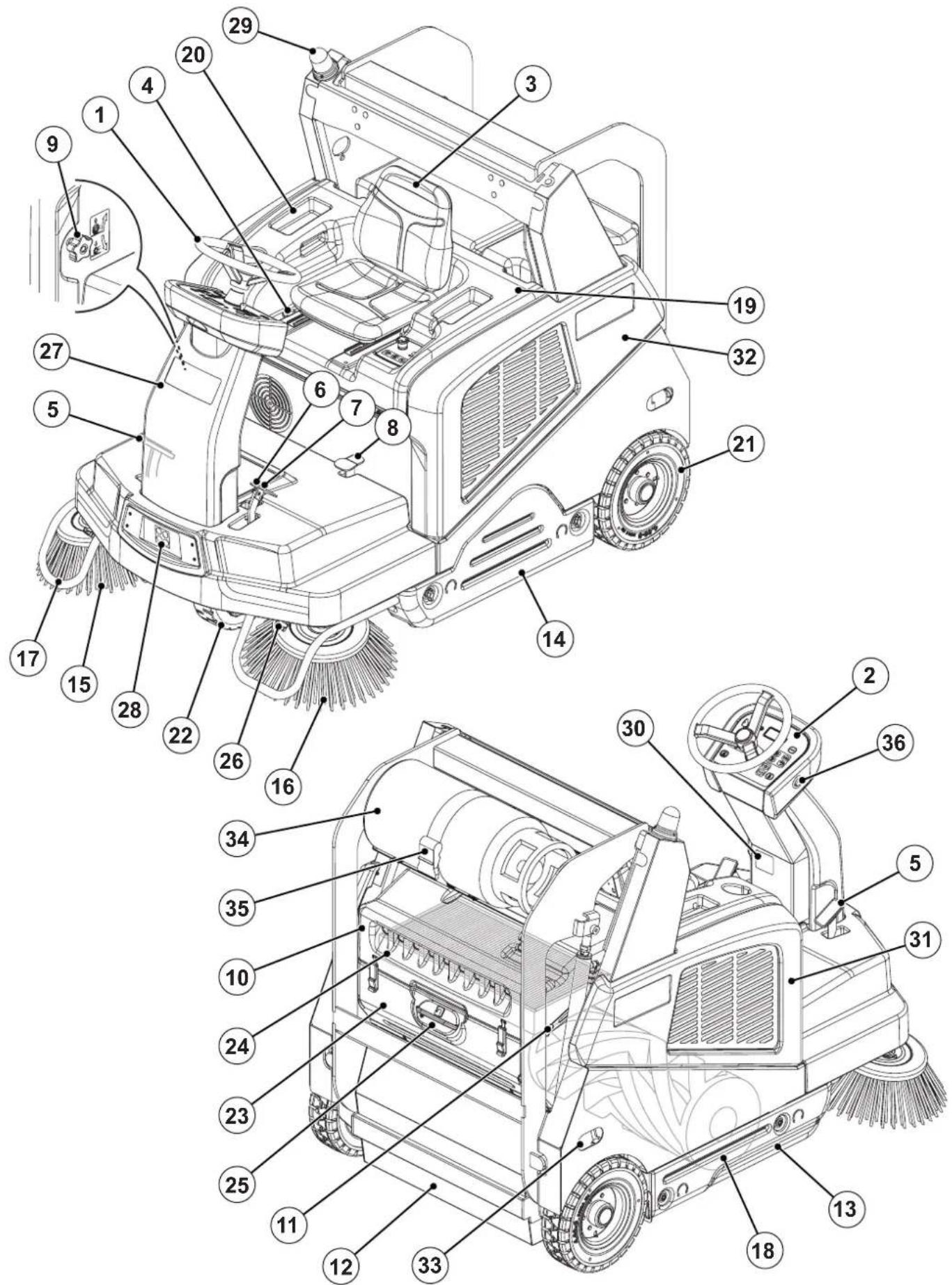
MACHINE DESCRIPTION
MACHINE STRUCTURE
- Steering wheel
- Control panel (see the following paragraph)
- Driver's seat with safety microswitch
- Seat position adjusting lever
- Accelerator pedal
- Service brake pedal
- Parking brake lever: press both the service brake (6) and the lever (7) to switch from the service brake to the parking brake
- Front skirt lifting pedal
- Main broom height adjusting knob:
- Turn it counter-clockwise to increase the broom pressure on the floor
- Turn it clockwise to decrease the broom pressure on the floor
- Vacuum system rear hood
- Vacuum system hood release lever
- Hopper (empty it when it is full)
- Right door (to be opened for performing maintenance procedures only)
- Left door (for main broom removal)
- Right side broom
- Left side broom (optional)
- Side broom guards (optional)
- Main broom
- Engine compartment hood
- Can holder
- Rear wheels
- Front driving and steering wheel
- Dust filter container / Dust guard system water tank (optional)
- Panel filter
- Dust guard system water filler neck plug (optional)
- Dust guard system nozzles (optional)
- Front column
- Working lights (optional)
- Flashing light (always on when the ignition key is turned to "I")
- Serial number/technical data/conformity certification plate
- Removable right side panel
- Removable left side panel
- Anchoring slots for transport (not for lifting)
- LPG tank (LPG version)
- LPG tank fastening band (LPG version)
- Engine off push-button (optional, only for hybrid version)
MACHINE STRUCTURE (Continues)
P100919
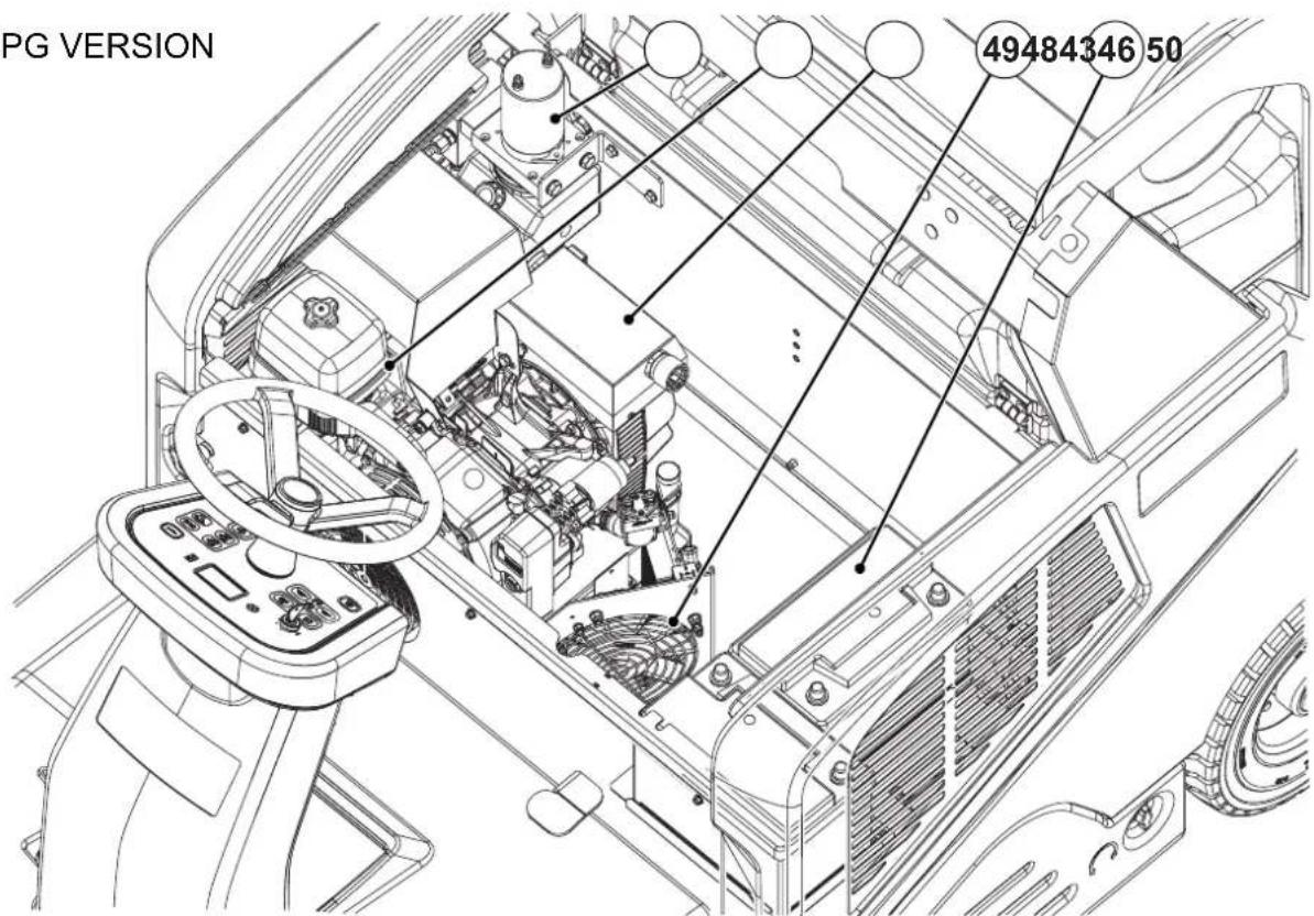
MACHINE STRUCTURE (Continues)
- Engine compartment hood (open)
- Diesel engine
- LPG engine
- Fuel tank
-
Fuel tank cap
-
Hydraulic unit with tank for hopper lifting
- Open hood safety rod
- Alternator
- Cooling fan
- Batteries
DIESEL VERSION

LPG VERSION
P100920
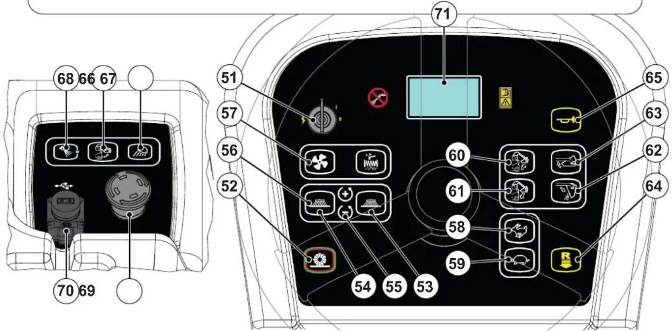
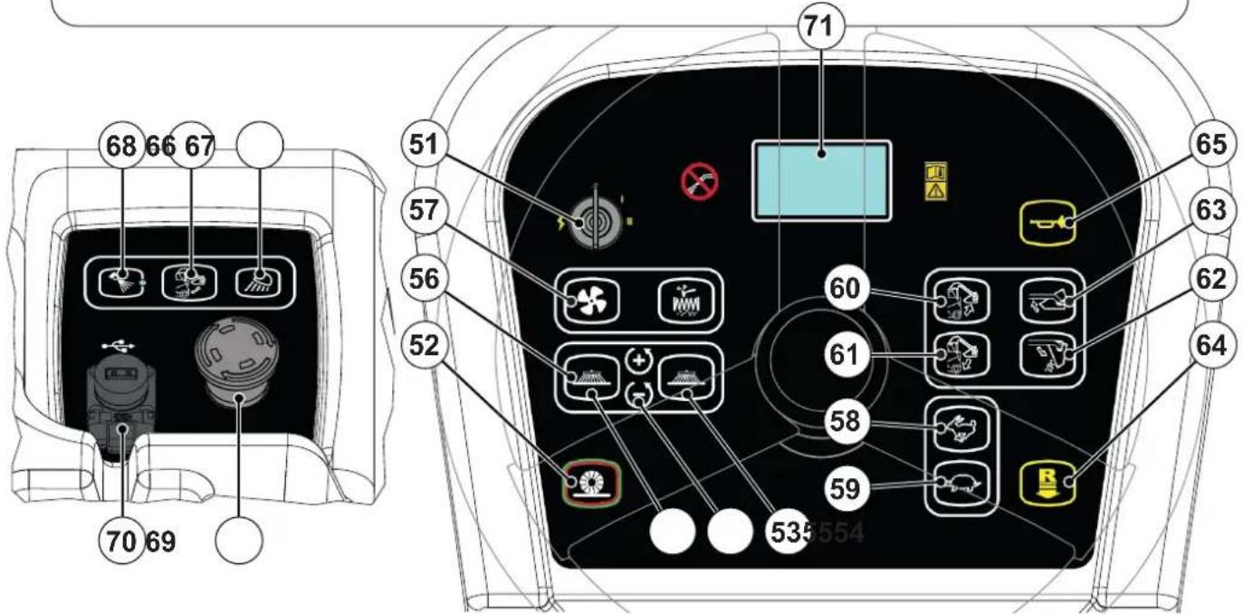
CONTROL PANEL
51. Ignition key:
- When turned to "0", it turns the electrical system off and disables all machine functions
-
When turned to "II", it starts the machine When the machine starts, release the key, which will return to "I" (machine ON)
-
One-Touch sweeping/vacuuming push-button
- Right side broom push-button
- Left side broom push-button
- Side broom rotation speed adjustment push-buttons
- Vacuum push-button
- Filter shaker push-button
- Increase maximum running speed push-button
- Decrease maximum running speed push-button
- Hopper lifting push-button
- Hopper lowering push-button
- Hopper dumping push-button
- Hopper reset push-button
- Reverse gear/forward gear reset push-push-button
- Horn push-button
- Hopper movement enabling push-button
- Working light push-button (optional)
- DustGuard™ system push-button (optional)
- Emergency push-button. Press it in case of emergency to stop all the machine functions.
To deactivate the emergency push-button, turn it in the direction shown by the arrow.
70. USB socket (optional)
71. Multifunction display Items displayed:
A) Working hours
B) Battery type
C) Maximum running speed setting
D) Work screen
E) Main broom activation
F) Side brooms activation
G) Vacuum activation
H) Reverse gear activation
I) Side brooms speed setting
J) Auto-shut off timer
K) Hopper opening warning
L) DustGuard™ system
M) Work light turned on
N) Main broom worn out
O) Service call
P) Fuel reserve warning
Q) Engine overheat warning
R) Engine oil pressure warning
S) Alternator warning


P100921
ACCESSORIES/OPTIONS
In addition to the standard components, the machine can be equipped with the following accessories/options, according to the machine specific use:
- Left side broom
- Right and left armrests
- Main and side brooms with harder or softer bristles
- Non-marking wheels
- Paper dust filter
- FOPS protective roof
- Non-marking skirts
- Roof cover
- Working light
- Side broom guards
- Safety belts
- DustGuard™ system
- Sprung seat
- USB™ socket
- Hybrid motor
For further information concerning the optional accessories, contact an authorised Retailer.
TECHNICAL DATA
| Model SW5500 D SW5500 LPG - | FLOORTEC R 985 LPG | ||
| Cleaning width with one side broom 1,175 mm | |||
| with two side brooms 1,500 mm | |||
| Main broom size (length x diameter) 850 x 360 mm | |||
| Side broom diameter 500 mm | |||
| Hopper capacity 150 litres | |||
| maximum liftable weight 240 kg | |||
| maximum lifting height 1,650 mm | |||
| Filter | cleaning system | Electrical filter shaker | |
| area | 7\ m2 | ||
| filter efficiency | 77 % @ 0,8 μm | ||
| Power | 4.1 kW (5.5 hp) @ 3,000 rpm | 5.7 kW (7.6 hp) @ 3,000 rpm | |
| Engine model | Yanmar L70N | Honda iGX 270 | |
| Fuel type | Diesel | LPG | |
| Fuel tank capacity | 7 litres | 15 Kg | |
| Type of engine oil | SAE 15W40 | SAE 10W30 | |
| Hopper hydraulic lifting system | Arnica 46 | ||
| Main broom | motor power | 1,250 W | |
| speed | 4,800 rpm | ||
| Side broom | motor power | 120 W | |
| speed (variable) | 40/155 rpm | ||
| Vacuum | motor power | 260 W | |
| Drive | type | Electrical on the front wheel | |
| gearmotor power | 1,200 W | ||
| forward speed | 10 km/h | 10 km/h | |
| reverse speed | 4.5 km/h | 4.5 km/h | |
| Maximum gradient when working | 20 % | ||
| Hopper hydraulic control unit | 800 W | ||
| Filter shaker motor | 2 x 12 W | ||
| Total absorbed power | 2.6 kW | ||
| Dimensions(length x width x height) | machine body | 1,875 x 1,200 x 1,564 mm | |
| machine with side brooms | 1,875 x 1,300 x 1,564 mm | ||
| machine with FOPS protective roof (optional) | 1,875 x 1,200 x 1,990 / 2,075 mm | ||
| LPG tank maximum size (length x diameter) | - | 886 x 306 mm | |
TECHNICAL DATA (Continues)
| Model SW5500 D SW5500 LPG - | FLOORTEC R 985 LPG | |
| Weight weight 757 Kg 764 Kg | ||
| total weight (*) 838 Kg 871 Kg | ||
| front axle weight (*) 354 Kg 365 Kg | ||
| rear axle weight (*) 484 Kg 506 Kg | ||
| gross vehicle weight (GVW) 1.098 Kg 1.142 Kg | ||
| Wheel specific pressure on the floor (front - rear wheels, in running conditions) 0.7 - 0.4 N/mm | 2 | 0.7 - 0.5 N/mm 2 |
| Sound pressure level at workstation (ISO 11201, ISO 4871, EN 60335-2-72) (LpA) | 85 dB(A) ± 3 dB(A) | 79 dB(A) ± 3 dB(A) |
| Machine sound pressure level (ISO 3744, ISO 4871, EN 60335-2-72) (LwA) | 104 dB(A) | 98 dB(A) |
| IP protection class | X3 | |
| Dust guard system water tank (optional) capacity | 32 litres | |
| U-turn space (right - left) | 2,310 - 2,375 mm | |
| Vibration level at the operator's arms (ISO 5349-1) (**) | < 2.5 m/s 2 | |
| Vibration level at the operator's body (ISO 2631-1) (**) | 0.8 m/s 2 | |
(*) With operator on board, fuel tank and hopper empty.
(**) Under normal working conditions, on a level asphalt surface.
Machine Material Composition and Recyclability
| Type | Recyclable percentage | SW5500 D weight percentage | Weight percentage of the SW5500 LPG - FLOORTEC R 985 LPG |
| Aluminium | 100 % | 0.2 % | 0.1 % |
| Electric motors - various | 29 % | 15.1 % | 20.4 % |
| Ferrous materials | 100 % | 65.6 % | 61.1 % |
| Wiring harnesses | 80 % | 0.0 % | 0.0 % |
| Liquids | 100 % | 0.6 % | 0.6 % |
| Plastic - non-recyclable material | 0 % | 0.0 % | 0.0 % |
| Plastic - recyclable material | 100 % | 1.1 % | 0.8 % |
| Polyethylene | 92 % | 8.3 % | 8.1 % |
| Rubber | 20 % | 9.0 % | 8.7 % |
| Cardboard - paper - wood | 100 % | 0.2 % | 0.1 % |
Hydraulic oil technical data
| Viscosity at 40 °C | mm2/s | 45 | 32 |
| Viscosity at 100 °C | mm2/s | 7.97 | 6.40 |
| Viscosity index | / | 150 | 157 |
| Flash point COC | °C | 215 | 202 |
| Pour point | °C | -36 | -36 |
| Density at 15 °C | kg/l | 0.87 | 0.865 |

CAUTION!
If the machine is to be used at ambient temperatures below +10 °C, the oil should be changed with equivalent oil having a viscosity of 32 cSt. For temperatures below 0 °C, use an oil with lower viscosity.
DIESEL VERSION WIRING DIAGRAM
Key
| A1 Main broom actuator | |
| A2 Right side broom actuator | |
| A3 Left side broom actuator (optional) | |
| ALT Alternator | |
| BAT1 12 V batteries | |
| BAT2 12 V batteries | |
| BZ Reverse gear buzzer | |
| BE Flashing light | |
| CH Battery charger (optional) | |
| D1..D3 Diode | |
| EB1 Function electronic board | |
| EB2 Drive system electronic board | |
| EB3 Display board | |
| EB4 Dashboard electronic board | |
| EB5 Seat dashboard electronic board | |
| ECN Encoder | |
| ES1 Function electronic board electromagnetic switch | |
| ES2 Drive system electronic board electromagnetic switch | |
| ES6 Fan relay | |
| ES7 Engine power relay | |
| ES8 Drive system enabling relay | |
| ES9 Horn relay | |
| ES10 Charging system electromagnetic switch | |
| ES11 Hybrid charging system relay | |
| EV1 Hopper raising solenoid valve | |
| EV2 Hopper lowering solenoid valve | |
| EV3 Hopper solenoid valve | |
| EV4 Fuel solenoid valve | |
| F1 Function electronic board fuse | |
| F2 Ignition key fuse | |
| F3 Drive system fuse | |
| F4 Alternator fuse | |
| F5 Engine fuse | |
| F7 Fan fuse | |
| F8 Horn fuse | |
| HN Horn | |
| KEY Ignition key | |
| L1 | Working light (optional) |
| M0 | Driving wheel |
| M1 | Vacuum system motor |
| M2 | Filter shaker motor |
| M3 | Hopper pump motor |
| M4 | Main broom motor |
| M5 | Right side broom motor |
| M6 | Left side broom motor (optional) |
| M7 | Engine compartment fan |
| MST Starter | |
| P1 Dust guard system pump motor (optional) | |
| P2 Fuel pump motor | |
| R1 Accelerator pedal | |
| R2,...4 | Resistance |
| S1 Opened hopper sensor | |
| S2 High hopper sensor | |
| S3 Rotated hopper sensor | |
| S4 Main broom wear sensor | |
| S5 Driving wheel temperature sensor | |
| S6 Fuel reserve sensor | |
| S7 Oil alert sensor | |
| S8 Diode jumper temperature sensor | |
| SW0 | Emergency push-button |
| SW1 | Driver's seat safety microswitch |
| TU Trackunit (optional) | |
| USB | USB port (optional) |
Colour codes
| BK Black | |
| BU | Blue |
| BN | Brown |
| GN | Green |
| GY Grey | |
| OG | Orange |
| PK Pink | |
| RD Red | |
| VT Violet | |
| WH White | |
| YE Yellow | |
DIESEL VERSION WIRING DIAGRAM (Continues)
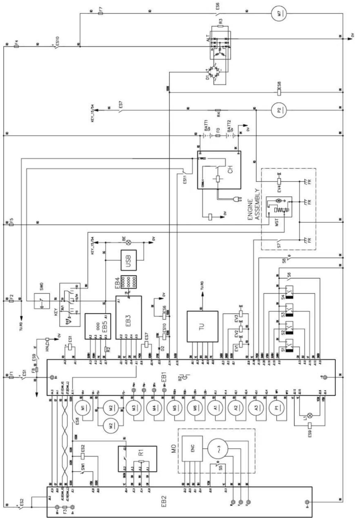
P100922
LPG VERSION WIRING DIAGRAM
Key
| A1 Main broom actuator | |
| A2 Right side broom actuator | |
| A3 Left side broom actuator (optional) | |
| ALT Alternator | |
| BAT1 12 V batteries | |
| BAT2 12 V batteries | |
| BZ Reverse gear buzzer | |
| BE Flashing light | |
| CCOIL Charging coil | |
| CH Battery charger (optional) | |
| D1..D3 Diode | |
| EB1 Function electronic board | |
| EB2 Drive system electronic board | |
| EB3 Display board | |
| EB4 Dashboard electronic board | |
| EB5 Seat dashboard electronic board | |
| EB6 Honda engine ECM | |
| EB7 Honda engine ignition coil | |
| ECN Encoder | |
| ES1 Function electronic board electromagnetic switch | |
| ES2 Drive system electronic board electromagnetic switch | |
| ES3 Engine on/off relay | |
| ES4 Engine RPM relay | |
| ES5 Engine start relay | |
| ES6 Fan relay | |
| ES8 Drive system enabling relay | |
| ES9 Horn relay | |
| ES10 Charging system electromagnetic switch | |
| ES11 Hybrid charging system relay | |
| EV1 Hopper raising solenoid valve | |
| EV2 Hopper lowering solenoid valve | |
| EV3 Hopper solenoid valve | |
| EV4 Fuel solenoid valve | |
| F0 Battery fuse | |
| F1 Function electronic board fuse | |
| F2 Ignition key fuse | |
| F3 Drive system fuse | |
| F4 Alternator fuse | |
| F5 Engine fuse | |
| F6 Engine start fuse | |
| F7 Fan fuse | |
| F8 Horn fuse | |
| HN Horn | |
| KEY | Ignition key |
| L1 | Working light (optional) |
| M0 | Driving wheel |
| M1 | Vacuum system motor |
| M2 | Filter shaker motor |
| M3 | Hopper pump motor |
| M4 | Main broom motor |
| M5 | Right side broom motor |
| M6 | Left side broom motor (optional) |
| M7 | Engine compartment fan |
| MST Starter | |
| P1 Dust guard system pump motor (optional) | |
| R1 Accelerator pedal | |
| R2,...4 | Resistance |
| S1 Opened hopper sensor | |
| S2 High hopper sensor | |
| S3 Rotated hopper sensor | |
| S4 Main broom wear sensor | |
| S5 Driving wheel temperature sensor | |
| S6 Fuel reserve sensor | |
| S7 Oil alert sensor | |
| S8 Diode jumper temperature sensor | |
| SPK | Engine spark plug |
| SW0 | Emergency push-button |
| SW1 | Driver's seat safety microswitch |
| TU Trackunit (optional) | |
| USB | USB port (optional) |
Colour codes
| BK Black | |
| BU | Blue |
| BN | Brown |
| GN | Green |
| GY Grey | |
| OG | Orange |
| PK Pink | |
| RD Red | |
| VT Violet | |
| WH White | |
| YE Yellow | |
LPG VERSION WIRING DIAGRAM (Continues)
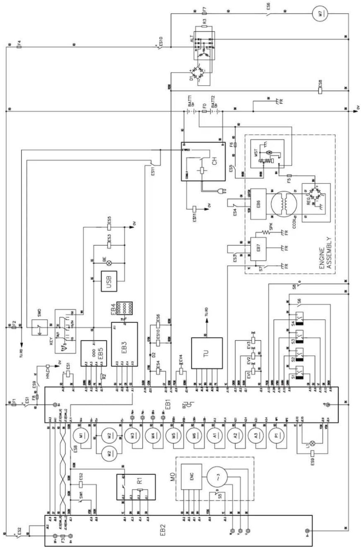
P100923
USE

WARNING!
On some points of the machine there are some adhesive plates indicating:
- DANGER
- WARNING
- CAUTION
- CONSULTATION
While reading this Manual, the operator must pay particular attention to the symbols shown on the plates (see the Visible Symbols On The Machine paragraph).
Do not cover these plates for any reason and immediately replace them if they are damaged.
If the machine has not been used after being transported, check that all the blocks have been removed.
FUEL

DANGER!


- Carbon monoxide (CO) can cause brain damage or death.
– The internal combustion engine of this machine can emit carbon monoxide. - Do not inhale exhaust gas fumes.
- Only use indoors when adequate ventilation is provided, and with the help of an assistant.
Fuel for Diesel version

CAUTION!
- Always stop the engine before filling the fuel tank.
- Do not smoke while filling the fuel tank.
– Fill the fuel tank in a well-ventilated area. -
Do not fill the fuel tank near sparks or open flame.
-
Open the engine compartment hood (19) and check that it is fastened with the support rod (47).
- Unscrew the plug (45) of the fuel tank (44) and refuel. Do not overfill and wipe any fuel accidentally spilled out.
- Never not use old or contaminated diesel fuel, and prevent dirt or water from entering the fuel tank.
Supply for LPG version

DANGER!
Before replacing the LPG tank, close the safety valve and disconnect the hose.
- Install an LPG tank (34) having characteristics which comply with the laws in force in the country where it is used.
- Fasten the tank with a fastening band (35).
- Connect the hose and open the cut-off valve on the LPG tank. Always wear gloves when connecting and disconnecting the hose. When the machine is not operating, close the LPG tank cutoff valve.

NOTE
Place the LPG tank in a proper horizontal position. Connect the hose to the tank and check that there are no gas leaks.

DANGER!
Do not use the machine in case of gas leaks. Disconnect the hose and replace the LPG tank. If the gas leak persists, disconnect the hose and contact the Nilfisk Service Center.
BEFORE MACHINE START-UP
Checklist
- Have a full knowledge of the machine operating controls and their functions.
- Insert the key (51) and start the machine (see the procedure in the following paragraph).
- In the first 2 seconds after turning on, the multifunction display (71) shows the machine working hours (71-A), the type of batteries set (71-B) and the current maximum machine speed setting (71-C).
- Check the fuel reserve icon (71-P); if it is lit, range will be limited. Refuel with diesel or replace the LPG tank (see previous paragraph).
- Check the horn with switch (65), the reverse gear buzzer with switch (64) and the working light switch (67, optional) for proper operation.
- Check the parking brake (7 and 6). The brake must hold its (locked parked) setting firmly without easily being released (report all defects immediately to Nilfisk Service Center).
- Check the service brake pedal (6) for proper operation.

WARNING!
If the pedal is “spongy” or fades under pressure without an efficient braking force, do not drive the machine (report all defects immediately to Nilfisk Service Center).
- Make sure that there are no open doors/hoods and that the machine is in normal operating conditions.
Cleaning planning
- Arrange long runs with a minimum of stopping or starting.
- Allow a small amount of broom path overlap to ensure complete coverage.
- Avoid making sharp turns, bumping or scraping the side of the machine.
Filling the DustGuard™ system water tank (optional)
- Remove the plug (25) to reach the filler neck.
- Fill the tank (24) with clean water. Do not fill the tank completely, leave a few centimetres from the edge.
STARTING AND STOPPING THE MACHINE
Starting the machine
- Sit on the driver's seat (3) and adjust it with the lever (4) to allow easy reach of all controls.

NOTE
The driver's seat (3) is equipped with a safety sensor, which allows the machine to be driven only when the operator is on the driver's seat.
- Turn the ignition key (51) clockwise to the "l" position.
- Wait for the multifunction display to show the work screen (71-D).
- Turn the ignition key (51) to the start position "II", then release it when the engine starts.
- After starting, let the engine idle for a few seconds.

CAUTION!
When starting do not press the accelerator pedal (5).
- Disengage the parking brake.
- Drive the machine to the working area, manoeuvring it by turning the steering wheel with your hands (1) and pressing the accelerator pedal (5).
The speed can be adjusted by applying more or less pressure to the accelerator pedal (5).
The maximum running speed can be set with push-buttons (58) and (59). - The forward/reverse direction is selected with the relevant push-button (64) on the dashboard. Activation of reverse gear is indicated by the buzzer and on the display (71-H).

WARNING!
When steering, avoid abrupt direction changes, pay careful attention and drive the machine at slow speed, especially when the hopper is full or when operating on inclines.
Drive the machine slowly on inclines. Use the brake pedal (6) to control machine speed while descending inclines.
Do not turn the machine on an incline; drive straight up or down.

NOTE
The machine has an anti-skid safety system, which where necessary reduces speed when steering and when the machine is driving on a camber, regardless of the pressure applied to the pedal.
This reduction in speed is therefore not a malfunction but a characteristic which increases the stability and safety of the machine in all conditions.
Hybrid motor (optional)
- Perform steps 1 to 3 of the machine start-up paragraph.
- Ignition of the engine is not necessary while the batteries retain a sufficient level of charge.
- Check the battery charge while working. While at least one segment of the battery icon (A, Fig. 1) is lit and not flashing on the multifunction display (71), the machine can be used with the engine off. When the battery icon (A) has only one flashing segment remaining it is advisable to start the engine, or else to recharge the batteries using the on-board battery charger (see procedure in the Maintenance chapter).
- To start using the machine again with the engine off, press the push-button (36) and hold it down until the engine turns off.
- When the multifunction display shows screen (B), a complete battery charging cycle must be performed using the on-board battery charger. Complete the job in progress before taking the machine to the area for charging its batteries.
- Perform a complete charging cycle before using the machine again (see procedure in the Maintenance chapter).
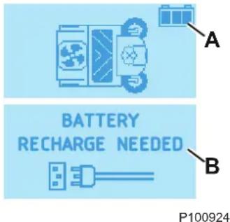
Figure 1
Stopping the machine
- To stop the machine, release the accelerator pedal (5).
- To stop the machine quickly, also press the service brake pedal (6).

WARNING!
The machine regulates its speed in proportion to the pressure on the accelerator pedal, accelerating and decelerating as a result. In some particular working and environmental conditions (e.g. steep descents), the automatic deceleration may deactivate itself to protect the system. For this reason, always use the service brake (6) to be sure of the machine's stopping distance.
- In case of emergency, press the emergency push-button (69) to immediately stop the machine. To deactivate the emergency push-button (69), turn it clockwise.

WARNING!
The emergency push-button (69) also deactivates the machine's automatic deceleration system; if operated while moving, use the service brake (6) to stop the machine.
- Turn the ignition key (51) to "0" and remove it.
PARKING BRAKE
- Engage the parking brake by pressing the pedal (6) and engaging the lever (7).
- Disengage the parking brake by pressing and releasing the pedal (6).
Before performing any maintenance, repair, cleaning or replacement procedure engage the parking brake. Engage the parking brake when parking the machine on a slope.
Before leaving the machine unattained, be sure that the parking brake can stop the machine with a large safety margin.
When using the machine on slopes, respect the maximum gradient values marked on the machine itself (see technical characteristics table).

WARNING!

WARNING!

WARNING!
MACHINE OPERATION
- Drive the machine to the work area as shown in the previous paragraph.
- Start cleaning by lowering the main broom and activating the vacuum system with the One-Touch push-button (52).
- (Optional) activate the DustGuard™ system with the corresponding push-button (68).
- Lower the side brooms with the push-buttons (53) and (54, optional). If necessary, adjust the speed of the side brooms with the + and - push-buttons (55, icon on display 71-l).

NOTE
The brooms (18, 15 and 16) can be lowered and lifted even when the machine is moving.
When the brooms are lowered, the brooms, the vacuum system and the dust guard system (optional) automatically activate only when the machine is moving.

NOTE
The side broom icons (71-F) keep the operator informed of the working configuration of the side brooms. When the icon is present, the corresponding side broom is activated and deactivated together with the main broom via the One-Touch push-button (52).
- Start sweeping by driving the machine with the hands on the steering wheel (1) and by pressing the accelerator pedal (5). If necessary, set the maximum speed with the push-buttons (58) and (59).
- Drive the machine straight forward at a quick walking speed. Drive the machine slower when sweeping large amounts of dust or debris or when safe operation dictates slower speeds. Overlap passes 10 cm.
- To collect light and bulky waste materials, lift the front skirt by pressing the pedal (8); take into consideration that the machine vacuum capability is reduced when the front skirt is lifted.

WARNING!
When operating on wet floors, it is essential to turn off the vacuum system by pressing the push-button (56) to prevent the dust filter from being damaged.
- For machine proper operation, the dust filter must be as clean as possible. To clean it while sweeping, operate the filter shaker by pressing the push-button (57).
While working, repeat the procedure every 10 minutes on average (depending on the dustiness of the area to be cleaned).

NOTE
This procedure can also be performed when the machine is moving.

CAUTION!
When the dust filter is clogged and/or the hopper is full, the machine cannot collect dust and debris anymore.
- The hopper (12) should be dumped after each working period and whenever it is full (see the procedure in the next paragraph).

CAUTION!
The engine is equipped with a warning system to prevent damages to the engine itself in case the oil quantity in the carter is insufficient. Before the oil level goes below the safety limit, the warning system automatically stops the engine and displays the icon (71-R) on the multifunction display.

CAUTION!
In the event of an overload of one of the broom motors, due to foreign bodies blocking it or excessive pressure of the broom on the ground (see procedure in the Main/Side Broom Height Check and Adjustment paragraph of the Maintenance chapter), a safety system stops the motor.
HOPPER DUMPING

WARNING!
The hopper (12) must be emptied on level grounds only. Do not lift the hopper when the machine is on a slope.

WARNING!
When lifting and dumping the hopper (12), make sure that there are no people around the machine, especially near the hopper.

NOTE
When the hopper (12) is lifted, the vacuum system turns off automatically and the machine maximum speed is reduced for safety reasons.
To empty the hopper, move the machine close to the dustbin and proceed as follows.
- Lift the side and main brooms.
- Press the enable push-button (66) while pressing the hopper lifting push-button (61) to lift the hopper (A, Fig. 2) up to the desired position.
- Drive the machine to the disposal area and engage the parking brake.
- Rotate the hopper (B) with the enable push-button (66) and push-button (62) to dump the accumulated waste (C).

CAUTION!
The hopper (A) can be dumped only when lifted at a minimum height of 35 cm approximately. The maximum dumping height is approx. 150 cm.
- Rotate the hopper back with the enable push-button (66) and push-button (63).
- Lower the hopper by pressing both the enable push-button (66) and push-button (61) at the same time.

CAUTION!
Check that the hopper opening icon (71-K) on the display disappears and the buzzer stops to be sure that the hopper (12) has fully returned to its working position.
- The machine is ready to start sweeping again.
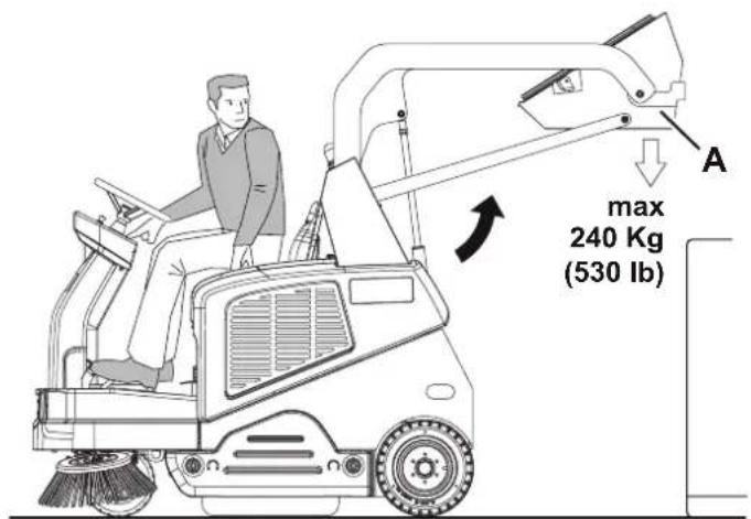
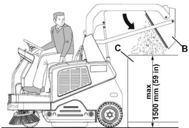
Figure 2
P100895
AFTER USING THE MACHINE
After working, before leaving the machine, perform the following procedures.
- Activate the filter shaker briefly by pressing the push-button (57).
– Empty the hopper (12) (see the procedure in the previous paragraph). - Raise the brooms with the One-Touch push-button (52).
(Only for LPG version). Close the safety valve on the LPG tank (32), then let the engine run until all the fuel is expelled from the hoses (then the engine is stopped).
- Turn off the machine by turning the ignition key (51) to "0", then remove it.
- Engage the parking brake.

NOTE
If the machine is left parked and inoperative, with the ignition key (51) in the "I" position, for more than 5 minutes, the electrical system switches to a low power consumption mode (stand-by). To start work again, it is necessary to shut off and restart the machine with the ignition key (51).
MACHINE LONG INACTIVITY
If the machine is not going to be used for more than 30 days, proceed as follows:
- Perform the procedures shown in After Machine Use paragraph.
- Check that the machine storage area is dry and clean.
– (For Diesel version). Close the fuel tap (34).
– (For LPG version). Close the LPG tank safety valve. - Disconnect the negative connector (-) of the batteries (46).
- Handle the engine (42) as shown in the relevant Manual.
- (For machines equipped with dust guard system). Empty the tank (23) and clean the water filter (see the procedure in Maintenance chapter).
MAINTENANCE
The lifespan of the machine and its maximum operating safety are ensured by correct and regular maintenance.
The following table provides the scheduled maintenance. The intervals shown may vary according to particular working conditions, which are to be defined by the person in charge of the maintenance.
All scheduled or extraordinary maintenance procedures must be performed by qualified personnel, or by an authorised Service Center.

CAUTION!
Each time the Service icon scheduled maintenance.

is shown on the display (71), contact an authorised Nilfisk Service Center for
This Manual describes only the easiest and most common maintenance procedures.
For other maintenance procedures shown in the Scheduled Maintenance Table, refer to the Service Manual that can be consulted at any Service Center.

WARNING!
To perform maintenance procedures, the machine must be off, the ignition key removed, and, if necessary, the batteries must be disconnected.
Read carefully the instructions in the Safety chapter before performing any maintenance procedure.
SCHEDULED MAINTENANCE TABLE
| Procedure | Upon delivery | Every 10 hours | Every 50 hours | Every 100 hours | Every 200 hours | Every year |
| Engine oil level check (1) | ||||||
| Battery fluid level check (2) | ||||||
| Side and main broom height check | ||||||
| Engine air filter check (1) | ||||||
| Hopper dust filter check and cleaning (“A” method) (3) |
SCHEDULED MAINTENANCE TABLE (Continues)
| Procedure | Upon delivery | Every 10 hours | Every 50 hours | Every 100 hours | Every 200 hours | Every year |
| Hopper lifting system hydraulic oil level check (2) | ||||||
| Skirt height and operation check | ||||||
| Dust guard system water filter check and cleaning (optional) | ||||||
| Brake cables check/adjustment (*) (4) | ||||||
| Engine air filter cleaning (3) (3) | ||||||
| Hopper dust filter check and cleaning ("B" method) (3) | ||||||
| Filter shaker operation check (*) | ||||||
| Main broom drive belt visual inspection (*) | ||||||
| Engine oil change (5) (6) | ||||||
| Spark plug check/cleaning | ||||||
| Steering chain cleaning (*) | ||||||
| Steering chain check/adjustment (*) | ||||||
| Safety device operation check (2) | ||||||
| Engine baffle plate cleaning (7) | ||||||
| Brake drums check/adjustment/replacement (*) (4) | ||||||
| Hopper dust filter check and cleaning ("C" method) | (3) | |||||
| Main broom drive belt check and/or replacement (*) | ||||||
| Hopper gasket integrity check | (*) | |||||
| Lifted hopper sensor operation check/adjustment | (*) | |||||
| Motor carbon brush check and/or replacement | (*) | |||||
| Fuel filter cleaning (diesel) | (*) | |||||
| Paper engine air filter replacement | ||||||
| Spark plug replacement | ||||||
| Engine idle speed check/adjustment | (*) | |||||
| Valve clearance check/adjustment | (7) | |||||
| Hydraulic system oil change | (*) (8) | |||||
| Supply hose replacement (LPG) | (*) | |||||
| Engine combustion chamber cleaning | Every 500 hours (7) | |||||
| Fuel hose check/replacement (diesel) | Every 2 years (7) | |||||
(*) For the relevant procedure, refer to the Service Manual.
(1) Daily or after using the machine.
(2) Or before start-up.
(3) Or more often in dusty areas.
(4) Or more frequently if the machine is used on slopes.
(5) Or every 6 months.
(6) And after the first 20 running-in hours.
(7) Maintenance procedures to be performed by an authorised Honda/Yanmar dealer.
(8) Change the hydraulic system oil after 500 hours or every year.
MULTIFUNCTION DISPLAY SERVICE SCREENS
Main screen (E, Fig. 3)
- Turn the ignition key (51) to the starting position "I" while holding down push-buttons (52) and (53) to access the main screen (E, Fig. 3).
- Press push-button (A) to change the machine settings (see the Machine Settings Screen paragraph).
- Press push-button (B) to check any alarms stored by the machine (see the Alarms Memory Screen paragraph).
- Press push-button (C) to check the machine working hours (see the Hour Counter Screen paragraph).
- Press push-button (D) to exit super user mode and return to operator mode.
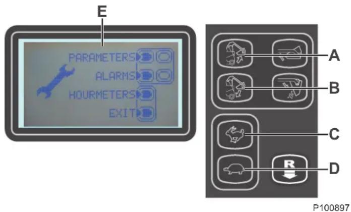
Figure 3
Machine Settings Screen (F, Fig. 4)
This function allows you to customise the value of the parameters described in the following table of modifiable parameters.
- To increase the value of the current parameter, press push-button (C).
To decrease the value of the current parameter, press push-button (D). - To move to the next parameter, press push-button (A).
- To return to the main screen, hold down push-button (B).
![F USL NEXT Max Side Brush Speed EXIT 50-100 + 100 [%] A B C D P100898](/content/2026/04/642729/images/afc53e1b5d9348e178ac7d3e4b93e8f439adf09e89dbbab40f8b90acd2f467ae.jpg)
Figure 4
| TABLE OF MODIFIABLE PARAMETERS Values | ||||
| Code Description | Minimum Factory Setting Maximum | |||
| VSL Side broom speed 50 % 100 % 100 % | ||||
| SCF | Filter shaker activation time | 5 sec | 20 sec | 60 sec. |
| FVMIN | Minimum forward speed | 0 % | 25 % | 100 % |
| FVMAX | Maximum forward speed | 10 % | 85 % | 100 % |
| RVMAX | Maximum reverse speed | 10 % | 30 % | 50 % |
| BAT (*) | Installed battery type (see table) | 0 | 0 | 1 |
| TOFF | Automatic shut-off time | 0 sec | 300 sec | 600 sec |
| BRGH | Display contrast | 5 | 25 | 50 |
| RESET | Resets all parameters to the factory default values | 0 | 0 | 1 |
| Installed Battery type | Value | |
| WET | Battery with liquid acid electrolyte | 0 |
| GEL / AGM | Generic GEL or AGM batteries | 1 |
(*) Significant only when the Hybrid Kit is installed
Alarms Memory Screen (G, Fig. 5)
This function allows you to check any alarms stored by the machine. Use this function only with the support of the Nilfisk Service Centre to solve problems with machine operation. To return to the main screen (E, Fig. 3), press push-button (A) repeatedly.
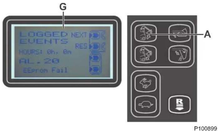
Figure 5
Hour counter screen (H, Fig. 6)
This function allows you to check the accumulated hours of operation for each of the machine's subsystems:
- TOTAL hour counter (machine on time)
– SIDE BROOMS hour counter (side brooms usage time) - MAIN BROOM hour counter (main broom usage time)
- DRIVE hour counter (drive system usage time)
- VACUUM hour counter (vacuum system usage time) To return to the main screen (E, Fig. 3), press push-button (A).
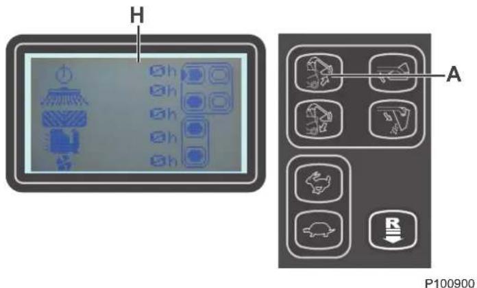
Figure 6
MAIN BROOM HEIGHT CHECK AND ADJUSTMENT

NOTE
Brooms with harder or softer bristles are available. This procedure is applicable to all types of brooms.
-
Check the main broom height as shown below:
-
Drive the machine on a level ground.
- Engage the parking brake.
- Lower the main broom with the One-Touch push-button (52).
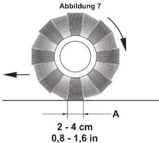
- Start broom rotation by pressing the One-Touch push-button (52) again and holding it down for 3 seconds.
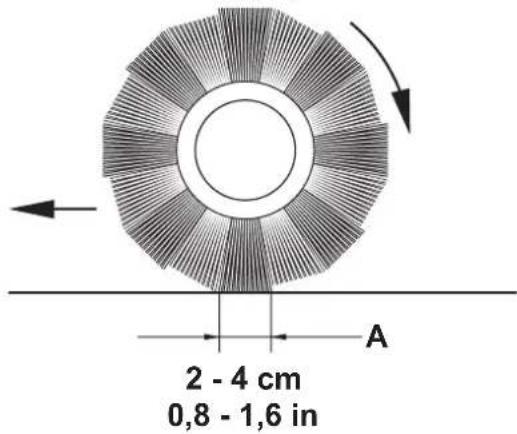
- After 30 seconds of broom operation (visible on the display, as per Figure 7), raise it by pressing the One-Touch push-button (52).
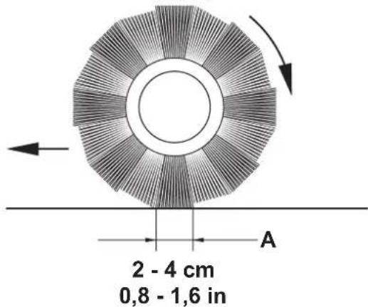
- Check that the main broom print (A, Fig. 8), along its length, is 2 to 4 cm wide.
If the print (A) is not within specifications, adjust the main broom height according to the following procedure.
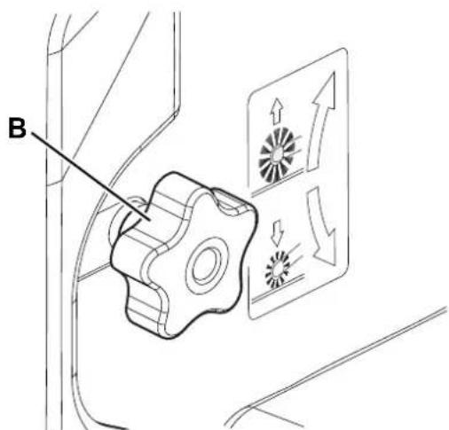
-
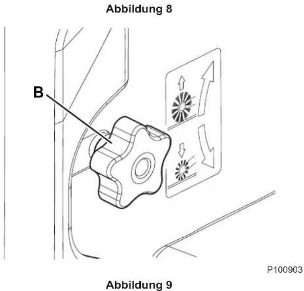
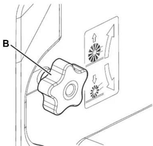
Turn the knob (B, Fig. 9) as shown below:
-
To increase the print width, turn the knob counterclockwise.
- To decrease the print width, lift the main broom with the One-Touch push-button (52) and then turn the knob clockwise.

NOTE
The knob can be used both to adjust the print and to adjust the broom according to the bristle wear.
- Perform step 1 again to check that the main broom is at the correct distance from the ground.
- When the icon (71-N) appears on the display, change the broom as described in the next paragraph.

NOTE
If it is not possible to adjust the print (A, Fig. 8) properly, because the pressure on the floor at the ends of the broom is different, refer to the Service Manual.

P100901
Figure 7
P100902
Figure 8
P100903
Figure 9
MAIN BROOM REPLACEMENT

WARNING!
It is advisable to wear protective gloves when replacing the main broom because there can be sharp debris between the bristles.
- Drive the machine on a level ground and engage the parking brake.
- Ensure that the main broom is in the lifted position.
- Turn the ignition key (51) to "0" and remove it.
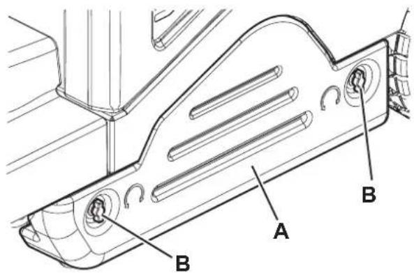
- Remove the left door (A, Fig. 10) by turning the fasteners (B).
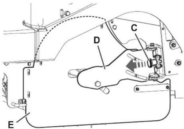
- Pull the knob (C, Fig. 11) as indicated by the arrow to disengage the closing support (D).
- Turn and open the closing support (D) together with the left side skirt (E).
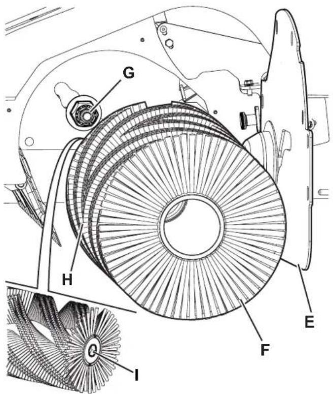
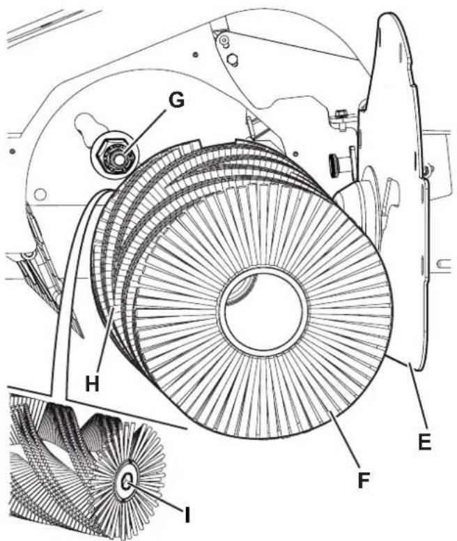
- Remove the main broom (F, Fig. 12).
- Check that the drive hub (G) is free from dirt or foreign materials (cords, rags, etc.) accidentally rolled up.
- The new main broom must be installed with the bristles rows bent as shown in the figure (H).
- Install the new main broom and ensure that the hexagonal mesh (I) fits into the relevant drive hub (G).
- Turn and close the closing support (D, Fig. 11); when closing, slightly pull the knob (C) until it clicks.

NOTE
When closing, manually push the main broom to engage it in the conical hub of the closing support (D).
- Refit the left door (A, Fig. 10) and close it with the fasteners (B).

CAUTION!
Check and adjust the main broom height as shown in the previous paragraph.
P100904
Figure 10

P100905
Figure 11
P100906
Figure 12
SIDE BROOM HEIGHT CHECK AND ADJUSTMENT

NOTE
Brooms with harder or softer bristles are available. This procedure is applicable to all types of brooms.
-
Check the side broom distance from the ground, according to the following procedure:
-
Drive the machine on a level ground.
- Keep the machine stationary, lower the side brooms and turn them on for a few seconds.
- Stop and lift the side brooms, then move the machine.
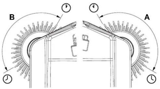
- Check that the side broom prints are as shown in the figure (A and B, Fig. 13).
If the print is not within specifications, adjust the side broom height according to the following procedure.
- Engage the parking brake.
- Turn the ignition key (51) to "0".
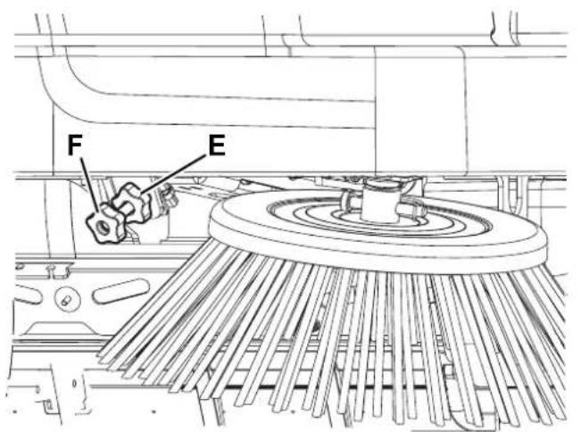
- For the right side broom, operate on the idle gear by loosening the knob (C, Fig. 14), then turn the adjustment knob (D) and note the following:
- To increase the print, turn the knob counter-clockwise. - To decrease the print, turn the knob clockwise.
- After adjusting, lock the idle gear with the knob (C).
- For the left side broom, operate on the idle gear by loosening the knob (E) and adjust the knob (F).
- After adjusting, lock the idle gear with the knob (E).
- Perform step 1 again to check the print of the side broom on the ground.
- When the broom is too worn to be adjusted, replace it as shown in the next paragraph.

NOTE
If necessary, the side broom tilting can be adjusted too (see the procedure in the Service Manual).
P100907
Figure 13

P100908
Figure 14
SIDE BROOM REPLACEMENT

WARNING!
It is advisable to wear protective gloves when replacing the side broom because there can be sharp debris between the bristles.
- Drive the machine on a level ground and engage the parking brake.
- Turn the ignition key (51) to "0".
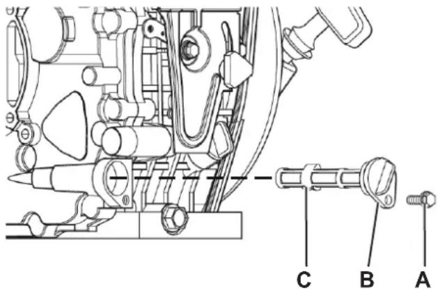
- Remove the pin clip (A, Fig. 15), then remove the pin.
- Remove the broom (B) and recover the protection flange (C).
- Install on the hub (D) the new side broom with the protection flange.
- Insert the fastening pin and engage its safety clip.
- Check and adjust the side broom height as shown in the previous paragraph.
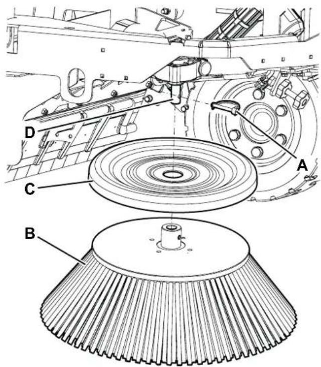
P100909
Figure 15
PANEL DUST FILTER CLEANING AND INTEGRITY CHECK
The dust filter must be regularly cleaned to maintain the efficiency of the vacuum system. Follow the recommended filter service intervals for the longest filter life.

WARNING!
- Wear safety glasses when cleaning the filter.
- Do not puncture the filter.
– Clean the filter in a well-ventilated area. -
Wear appropriate dust mask to avoid breathing in dust.
-
Drive the machine on a level ground, engage the parking brake and turn the ignition key (51) to "0".
- Open the engine compartment hood (19) and check that it is fastened with the support rod (47).
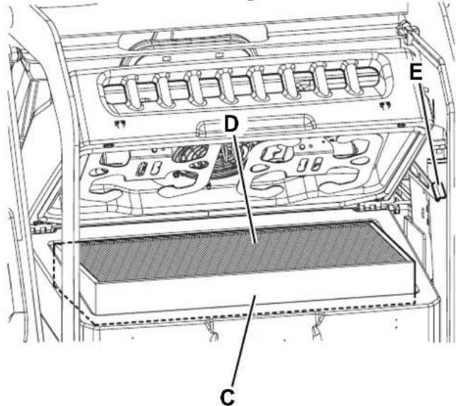
- Release the fasteners (A, Fig. 16) and open the vacuum system cover (B).
- Lift the dust filter (C, Fig. 17) and remove it from the machine.
- Clean the filter using one of the methods below:
Method "A"
Collect dust from the filter. Gently tap the filter against a flat surface (with the dirty side down) to remove dust and dirt.

NOTE
Take care not to damage the metal lip which extends past the gasket.
Method "B"
Collect dust from the filter. Blow compressed air (maximum pressure 6 Bar) into the clean side of the filter (in the opposite direction of the airflow).
Method "C" (only for optional polyester filter)

CAUTION!
For the paper filter: do not use water or detergents to clean it, otherwise the filter could be damaged.
Collect dust from the filter. Then soak the filter in warm water for 15 minutes, then rinse it under a gentle stream of water (maximum pressure 2.5 Bar). Let the filter dry completely before installing it back into the machine.
For a better cleaning, it is allowed to wash the filter with water and non-lathering detergents.
This provides better quality cleaning but reduces the life of the filter, which will have to be replaced more frequently. The use of inadequate detergents can damage the filter.
-
Install the filter in the reverse order of removal and note the following:
-
Clean the filter housing.
• Install the filter with the wire gauze upwards (D Fig. 17). -
If the filter gasket is damaged or missing, it must be replaced.
-
Press the lever (E) to disengage and close the cover (B, Fig. 16).
-
Engage the fasteners (A).
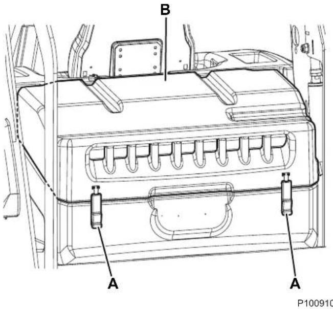
Figure 16

Figure 17
Preliminary Operations
-
Empty the hopper (as shown in Use chapter), because the weight of the waste inside the hopper can affect the skirt height check.
-
Drive the machine on a level ground that is suitable for checking the skirt height.
-
Turn the ignition key (51) to "0" and engage the parking brake.
Side Skirt Check
- Remove the left and right doors (14 and 13) by turning the fasteners.

NOTE
The right door fasteners (13) must be turned with a tool.
-
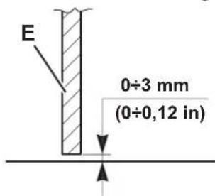
Check the condition of the side skirts (A, Fig. 18) and (B). Replace the skirts when they have cuts (C, Fig. 19) larger than 20 mm or cracks/tears (D) larger than 10 mm (for skirt replacement, refer to the Service Manual).
-
Check that the distance from the floor of the side skirts (A, Fig. 18) and (B) is within 0 - 3 mm (E, Fig. 20). If necessary, loosen the nuts (F, Fig. 18) and adjust the skirt position. Finally, tighten the nuts (F).
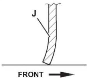
Front and Rear Skirt Check
- Remove the main broom as shown in the relevant paragraph.
- Check the condition of the front (G, Fig. 21) and rear skirts (H) and (I). Replace the skirts when they have cuts (C, Fig. 19) larger than 20 mm or cracks/tears (D) larger than 10 mm.
- Check that the front (G, Fig. 21) and rear skirt (I) slightly rub ground without being detached from it (J, Fig. 20).
- For the skirt replacement, see the Service Manual.
Reassembly
- Assemble the components in the reverse order of disassembly.
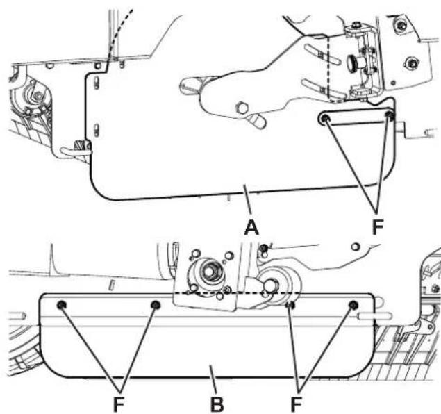
Figure 18
P100912
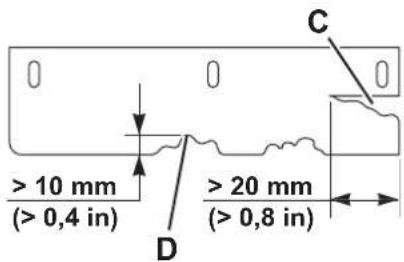
Figure 19
P100913
P100914
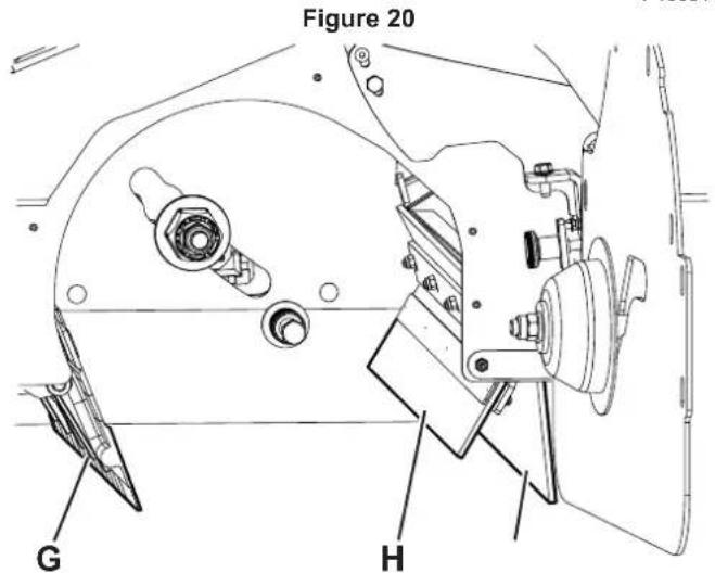
Figure 21
DUSTGUARD™ SYSTEM WATER FILTER CLEANING (OPTIONAL)

NOTE
To prevent water from flowing out when cleaning the filter, turn on the dust guard system and empty the system tank (23).
- Drive the machine on a level ground.
- Turn the ignition key (51) to "0" and engage the parking brake.
- Lift and remove the left side panel (32) to reach the water filter assembly (A, Fig. 22) of the dust control system.
- Unscrew and remove the transparent cover (B) with the gasket (C), then remove the filter strainer (D).
- Clean and install them on the support (E).

NOTE
Install the gasket (C) and the filter strainer (D) in the housings of the cover and of the filter assembly holder.
Figure 22
HYDRAULIC SYSTEM OIL LEVEL CHECK

WARNING!
Procedure to be performed with the hopper (11) fully retracted.
- Turn the ignition key (51) to "0" and engage the parking brake.
- Open the engine compartment hood (19) and fasten it with the support rod (47).
- Check that the oil level in the hydraulic system tank (46) is between the minimum (MIN) and maximum (MAX) marks shown in figure 23.
- If necessary, add oil through the plug (A), using the oil specified in Technical Data paragraph.
- Remove the support rod (47) and close the hood (19).
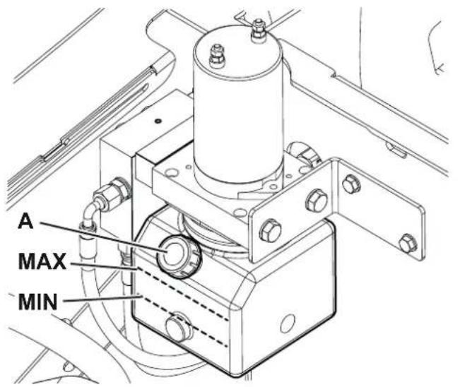
Figure 23
ENGINE OIL LEVEL CHECK AND OIL REPLACEMENT (DIESEL version)
Engine oil level check

CAUTION!
Running the engine with a low oil level can damage the engine itself.
- Drive the machine on a level ground and engage the parking brake.
- Turn the ignition key (51) to "0".
- Open the engine compartment hood (19) and fasten it with the support rod (47).
- Lift and remove the left side panel (32).
- Remove the cap (A, Fig. 24).
- Check the oil level. If it is below the upper limit (B), top up with the recommended oil until you reach the upper limit.
- Reinstall the filler cap (A) safely.
Engine oil change

CAUTION!
The discharged engine oil must be disposed of properly according to the Law in force.

NOTE
It is advisable to change the oil when the engine is still hot, to make the oil downflow easier.
- Perform steps 1 to 4 of the previous procedure.
- Remove the cap (A).
- Unhook the drain hose (C) and bring it towards the outside of the machine.
- Remove the oil drain plug (D) from the hose and drain the oil into a suitable container, then refit the oil drain plug and return the hose to its initial location.
- Pour the new oil through the filler (E) until it reaches the upper limit (B).

NOTE
As for engine oil type and quantity, see the Technical Data chapter and the Engine Manual.
- Reinstall the filler cap (A) safely.
DIESEL VERSION
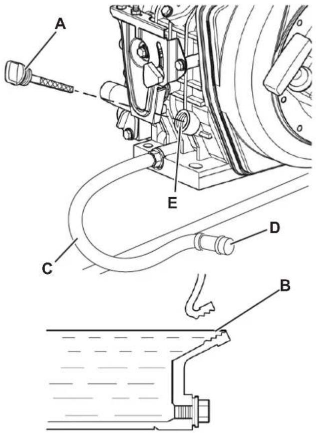
Figure 24
P100925
ENGINE OIL LEVEL CHECK AND OIL REPLACEMENT (LPG version)
Engine oil level check

CAUTION!
Running the engine with a low oil level can damage the engine itself.

NOTE
(LPG version). The oil alert system will automatically stop the engine before the oil level goes down under the safety limit. To avoid a sudden engine stop, always check the oil level before each start-up.
- Drive the machine on a level ground and engage the parking brake.
- Turn the ignition key (51) to "0"
- Open the engine compartment hood (19) and fasten it with the support rod (47).
- Lift and remove the right side panel (31).
- Remove the cap (A, Fig. 25).
- Check the oil level. If it is below the upper limit (E), top up with the recommended oil until you reach the upper limit.
- Reinstall the filler cap (A) safely.
Engine oil change

CAUTION!
The discharged engine oil must be disposed of properly according to the Law in force.

NOTE
It is advisable to change the oil when the engine is still hot, to make the oil downflow easier.
-
Perform steps 1 to 4 of the previous procedure.
-
Remove the cap (A, Fig. 25).
-
Unhook the drain hose (B) and bring it towards the outside of the machine.
-
Remove the drain plug (C) from the hose and drain the oil into a suitable container, then refit the oil drain plug and return the hose to its initial location.
-
Remove the filler cap (D) and pour in the new oil through the filler until it reaches the upper limit (E) of the cavity.

NOTE
As for engine oil type and quantity, see the Technical Data chapter and the Engine Manual.
- Reinstall the filler cap (D) and the cap (A) safely.
LPG VERSION
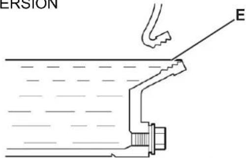
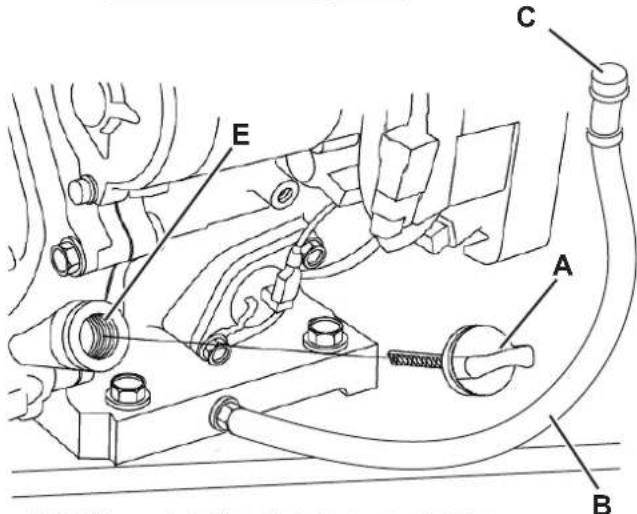

Figure 25
P100926
ENGINE OIL FILTERS CHECK/CLEANING (DIESEL version)
- Drive the machine on a level ground and engage the parking brake.
- Turn the ignition key (51) to "0".
- Open the engine compartment hood (19) and fasten it with the support rod (47).
- Lift and remove the left side panel (32).
- Remove the bolt (A, Fig. 26).
- Remove the cap (B) and remove the oil filter (C).
- Clean the oil filter, or replace it if damaged.
- Install the oil filter (C)
- Ensure that the oil filter plug (B) is completely inserted.
- Install and tighten the retaining bolt (A).
- Add engine oil as recommended (see the technical characteristics table and the engine manual).

CAUTION!
See the Engine Oil Level Check paragraph for the oil top-up procedure.
-
Warm up the engine for 5 minutes and check for any engine oil leaks.
-
Once the engine is warm, switch it off and leave it to cool for 10 minutes.
DIESEL VERSION
P100927
Figure 26
ENGINE AIR FILTERS CHECK/CLEANING (DIESEL and LPG version)
A dirty air filter limits the passage of air, thus reducing engine performance. When working in particularly dusty areas, clean or replace the filters more often than specified in the maintenance programme.

CAUTION!
Running the engine without air filters, or with damaged filters, can cause a faster engine wearing.
- Drive the machine on a level ground and engage the parking brake.
- Turn the ignition key (51) to "0".
- Open the engine compartment hood (19) and fasten it with the support rod (47).
- (DIESEL Version). Lift and remove the left side panel (32). (LPG version). Lift and remove the right side panel (31).
- Remove the wing nut (A, Fig. 27) and remove the cover (B).
- Remove the wing nut (C) and disassemble the filter element.
- Separate the paper filter (D) from the foam filter (E).
- Check both filters and replace them if necessary. Replace the paper filter (D) when required (see the scheduled maintenance table).
- To reuse the filters, clean them both by blowing compressed air [at no more than 207 kPa (2.1 kgf/cm)] inside the filter. Do not use a brush, otherwise the fibre will be damaged.
- Clean with a wet cloth the base and the cover (B) of the air filter. Take care to prevent dirt entering the air duct (G).
- Fit the foam filter (E) on the paper filter (D), then install the assembled filter element. Ensure that the gasket (F) is properly placed under the filter element. Screw down the filter element wing nut (C).
- Install the cover (B) and screw down the wing nut (A).
DIESEL VERSION
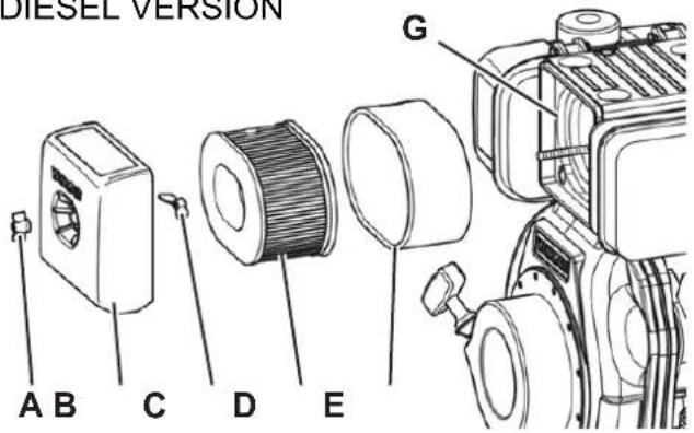
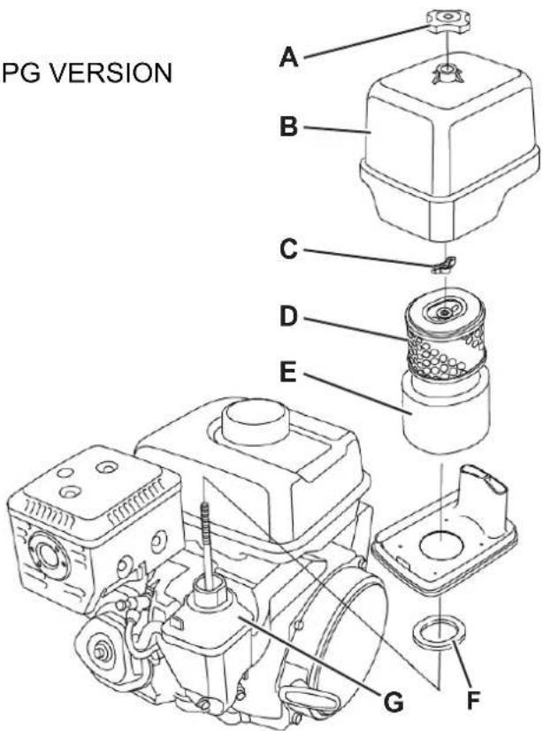
Figure 27
ENGINE SPARK PLUG CHECK/REPLACEMENT (LPG version)
For the type of spark plug to be used, see Technical Data chapter.

CAUTION!
A wrong spark plug can damage the engine.
- Drive the machine on a level ground and engage the parking brake.
- Turn the ignition key (51) to "0".
- Open the engine compartment hood (19) and fasten it with the support rod (47).
- Lift and remove the right side panel (31).
- Disconnect the spark plug cap (A, Fig. 28) and remove dirt around the spark plug (B).
- Remove the spark plug with a suitable wrench (C).
- Check the spark plug. Replace it if it is damaged, dirty, if the sealing washer (D) is damaged or if the electrode is worn.
- Measure the distance between the spark plug electrodes with a feeler gauge. Correct the distance by bending carefully the side electrode (E). The distance between the electrodes must be of 0.70 - 0.80 mm.
- Install the spark plug manually with great care, to avoid tightening it improperly.
- Once the spark plug is in place, tighten it with a proper wrench to press the sealing washer.
- When a new spark plug is installed, tighten 1/2 turn once the spark plug is in place to press the washer.
- When the original spark plug is reinstalled, tighten 1/8 - 1/4 turn once the spark plug is in place to press the washer.

CAUTION!
A loose spark plug can overheat and damage the engine.
Do not overtighten, otherwise the threads in the cylinder head can be damaged.
- Install the cap on the spark plug.
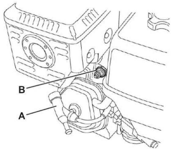
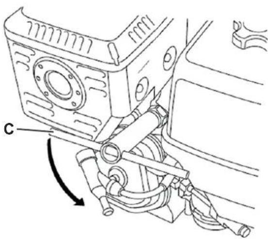

P100929
Figure 28
BATTERY CHARGING (only for version with optional hybrid KIT installed)

CAUTION!
Charge the batteries with the installed battery charger when the last segment of the battery icon
(A, Fig. 29) starts flashing 📄, or at the end of each job. Keeping the batteries charged make their life last longer.
Recharging is essential when the multifunction display shows screen (B).

WARNING!
When the batteries are discharged, charge them as soon as possible, as that condition makes their life shorter.
- Drive the machine on a level ground and engage the parking brake.
- Turn the ignition key (51) to "0".
- Connect the battery charger plug (D) to a mains electrical socket.

WARNING!
Check that the voltage and frequency shown on the battery charger plate (D) match the mains supply values.

NOTE
When the battery charger is connected to the electrical mains, all machine functions are automatically cut off. The multifunction display shows the screen (C) as in the figure.
- When the battery charger green battery symbol (E) is flashing, the batteries are recharging.
- When the battery charger green battery symbol (E) is lit steadily, the batteries are charged.
- For further information about the battery charger operation, see the Battery Charger Manual.
- Disconnect the battery charger cable from the electrical mains.
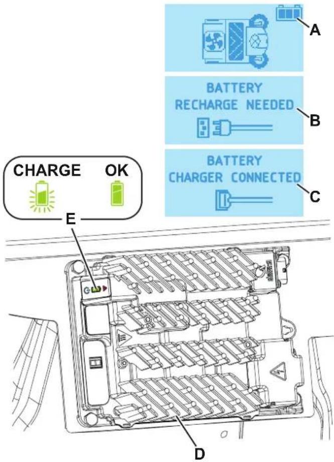
Figure 29
P100924
FUSE CHECK/REPLACEMENT

NOTE
All of the machine's electronic circuits are protected by electronic devices which reset automatically. The safety fuses blow only in the event of serious faults.
For this reason, fuses should only be replaced by qualified personnel.
Refer to the service manual available from Nilfisk retailers.
SAFETY FUNCTIONS
The machine is equipped with the following safety functions.
EMERGENCY PUSH-BUTTON
It is to the left side of the operator (69). It has to be pressed in case of emergency, to stop all the machine functions.
DRIVER'S SEAT MICROSWITCH
This is located inside the driver's seat (3) and it does not allow the machine to operate if the operator is not seated on the driver's seat.
ANTI-SKID SAFETY SYSTEM
Reduces speed to a safe value, where necessary, when steering and when driving on a camber, in order to prevent skidding and increase the machine's stability in all operating conditions.
MACHINE ANGLE SENSOR
If the hopper is to be raised with the machine not on level ground, the system reduces the speed of movement of the hopper and warns the operator that the machine stability conditions may be critical depending on the weight of refuse contained, via a different buzzer sound and the icon on the display (71) as shown in figure 30.
HOPPER POSITION SENSOR
When the hopper is lifted, the sensor reduces the machine speed, turns off the vacuum fan and stops the broom rotation.
HOPPER SAFETY VALVE
When the hopper is lifted, the safety valve on the hydraulic lifting cylinder prevents the hopper to accidentally lower.

8.
P100918
Figure 30
TROUBLESHOOTING
| Trouble Possible cause Remedy | ||
| The engine does not start with the ignition key, or stops during work. | The fuel does not reach the engine. | Check that the fuel valve is open (diesel). |
| Check that the tank safety valve is open (LPG). | ||
| The spark plug does not produce a spark (LPG). | Check or replace the spark plug. (*) | |
| The batteries are discharged. Recharge with a proper battery charger. | ||
| The emergency push-button has been pressed. | Check and release the emergency push-button. | |
| The engine does not start with the ignition key, or stops during work, and icon (71-R) appears on the multifunction display. | The engine oil level is too low. Check the engine oil level and top up. (*) | |
| The engine does not start with the ignition key, or stops during work, and icon (71-Q) appears on the multifunction display. | The temperature of the engine/alternator assembly is too high. | Wait for the engine to cool down before using the machine further.If possible, keep the hood open to facilitate cooling. |
| (For version with Hybrid Kit only). The machine operates only when stationary, otherwise it switches off when under load and theicon flashes. | The batteries are discharged. | Charge the batteries.If the trouble persists, replace the batteries. |
| (For version with Hybrid Kit only). The battery autonomy is low. | Batteries no longer in good condition. | Replace the batteries.If necessary, install batteries of a higher capacity. |
| When turning the ignition key to "I", the display does not turn on and the machine does not operate. | Emergency push-button activated. | Check and release the emergency push-button. |
| The machine does not move when the accelerator pedal is pressed, and an alarm message appears on the display. | Accelerator pedal pressed, while the ignition key is turned to the "I" position. | Turn the ignition key to "0", then restart without pressing the accelerator pedal. |
| The operator is not correctly seated on the driver's seat. | Sit down on the driver's seat. | |
| Drive system fault. | Turn off the machine and then turn it on again.If the trouble persists, contact the Service Center. | |
| The machine does not move and the icon (71-S) appears on the multifunction display. | Engine off. Switch on the engine. | |
| Alternator is faulty. Contact the Service Centre. | ||
| The machine moves more slowly than usual. | Hopper not completely closed. | Return the hopper to the horizontal position and lower it completely. |
| Machine started on a cambered surface and anti-skid system has lost correct reference. | Turn the machine off and then start it again on a flat surface. | |
| The main broom does not work and the corresponding icon on the display does not appear. | The safety system has tripped. | Turn off the machine and then turn it on again.Check the condition of the main broom (debris that slows down the broom or excessive pressure on the ground). |
| The side brooms do not operate. The safety system has activated. | Wait for the side broom motor to cool down, then reset the fuse by pressing the relevant push-button. | |
| The machine collects little debris/dust. | The dust filter is clogged. | Clean the dust filter by using the filter shaker or by disassembling it. |
| The hopper is full. Empty the hopper. | ||
| The skirts are not properly adjusted or are broken. | Adjust/replace the skirts. | |
| The brooms are not properly adjusted. Adjust the broom height. | ||
| The hopper does not lift. | Hydraulic system oil level incorrect. | Check the hydraulic system oil level in the tank. |
| Machine not level. Bring the machine back to a level surface | ||
| The hopper does not dump. The hopper is too low. | Lift the hopper at a minimum height of 350 mm. | |
| The hopper does not lower. | Hydraulic oil taking too long to flow through the safety valve due to low temperature. | Wait a few moments to let the hydraulic system oil flow. |
| The filter shaker does not work. Filter shaker d | sconnected. Connect the filter shaker connector. | |
| The dust guard system (optional) does not work. | Water tank empty. Fill the tank. | |
| The nozzles or the water filter are clogged. Clean. | ||
| The pump is faulty. Replace. (*) | ||
(*) For the relevant instructions, see also to the Engine Manual.
(**) Procedure to be performed by Nilfisk Service Center.
For further information contact a Nilfisk Service Center, where it is possible to consult the Service Manual.
SCRAPPING
Have the machine scrapped by a qualified scraper.
Before scrapping the machine, remove and separate the following materials, which must be disposed of properly according to the Law in force:
- Batteries
– Polyester dust filter
– Main and side brooms
– Hydraulic system oil
– Hydraulic system oil filter
– Plastic hoses and components
– Electrical and electronic components (*)
(*) Refer to the nearest Nilfisk Center especially when scrapping electrical and electronic components.
INHOUDSOPGAVE
INLEIDING 2
DOEL EN INHOUD VAN DEZE HANDLEIDING....2
BETREFFENDE PERSONEN 2
OPBERGEN VAN DE HANDLEIDING....2
CONFORMITEITSVERKLARING 2
IDENTIFICATIEGEGEVENS 2
ANDERE GEBRUIKERSHANDLEIDINGEN....3
VERVANGINGSONDERDELEN EN ONDERHOUD 3
MODIFICATIES EN VERBETERINGEN....3
BEDRIJFSCAPACITEIT 3
ALGEMENE OPMERKINGEN....3
VERPAKKING VERWIJDEREN/AFLEVERING 3
VEILIGHEID 3
SYMBOLEN OP DE MACHINE 4
SYMBOLEN IN DE HANDLEIDING....4
ALGEMENE INSTRUCTIES 4
BESCHRIJVING VAN DE MACHINE 8
BOUW VAN DE MACHINE 8
BEDIENINGSPANEELE EN KNOPPEN 11
ACCESSOIRES/OPTIES....12
P100919


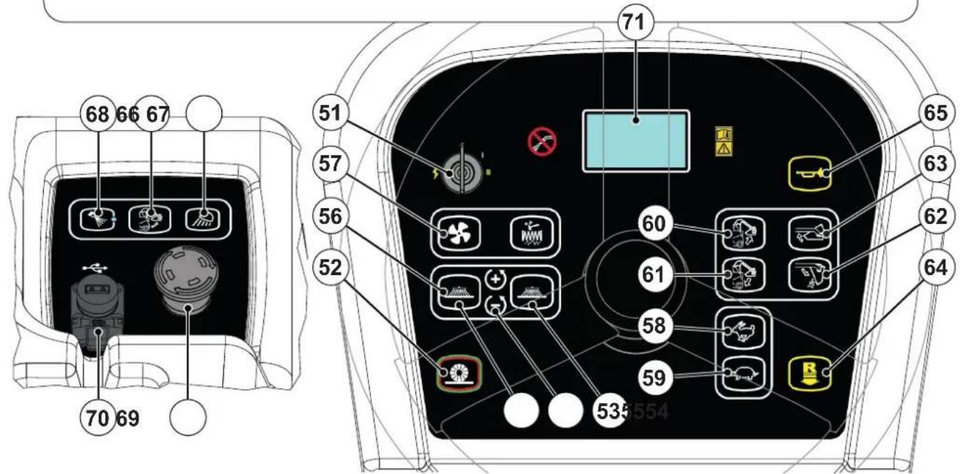
P100921
ACCESSOIRES/OPTIES
P100922
ELEKTRISCH SCHEMA LPG-UITVOERING
Legende
P100923
GEBRUIK

LET OP!
P100904
Afbeelding 10
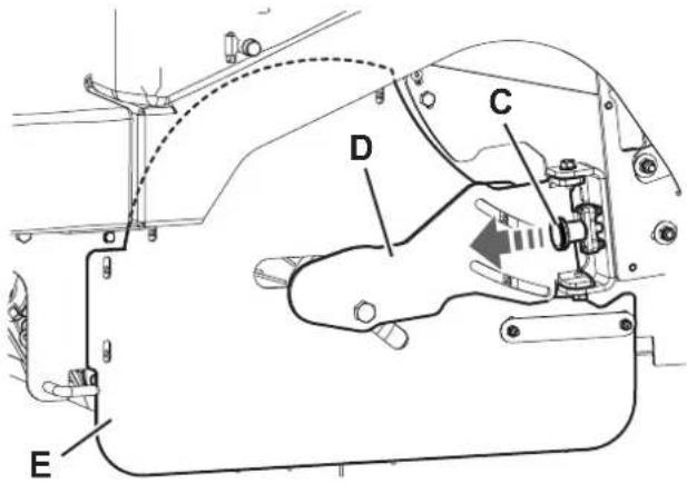
P100905
Afbeelding 11
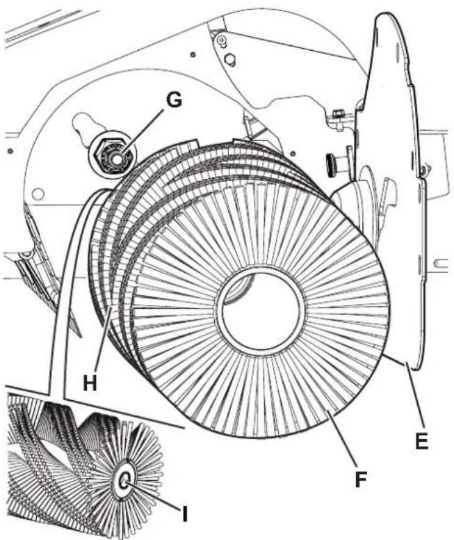
P100914
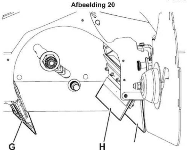
Afbeelding 22
CONTROLE VAN HET OLIEPEIL IN HET HYDRAULISCHE SYSTEEM

LET OP!
Afbeelding 23
P100917
CONTROLE VAN HET PEIL EN VERVERSING VAN DE MOTOROLIE (dieseluitvoering)
Controle motoroliepeil

WAARSCHUWING!

Afbeelding 25
P100926
CONTROLE/REINIGING VAN DE OLIEFILTERS VAN DE MOTOR (dieseluitvoering)
P100927
Afbeelding 26
CONTROLE/REINIGING VAN DE LUCHTFILTERS VAN DE MOTOR (diesel- en LPG-uitvoering)

Afbeelding 28
P100929
8.
P100918
Afbeelding 30
STORINGEN LOKALISEREN
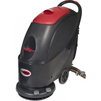
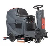
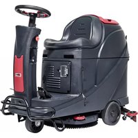
- SW5500, FLOORTEC R 985
- INSTRUCTIONS FOR USE
- INHALTSVERZEICHNIS
- EINLEITUNG......2
- SCHALTPLAN LPG-VERSION
- BETRIEB
- ACHTUNG
- WASSERFILTER DER DUSTGUARD™-STAUBABSCHEIDUNGSANLAGE (OPTION) REINIGEN
- KONTROLLE/REINIGUNG DER ÖLFILTER DES MOTORS (DIESEL-VERSION)
- DÉBALLAGE / LIVRAISON....3
- SÉCURITÉ 3
- DESCRIPTION DE LA MACHINE 8
- UTILISATION 18
- ENTRETIEN 23
- CONSERVATION DU MANUEL
- DÉCLARATION DE CONFORMITÉ
- STRUCTURE DE LA MACHINE
- STRUCTURE DE LA MACHINE (SUITE)
- ACCESSOIRES / OPTIONS
- SCHÉMA ÉLECTRIQUE VERSION GPL
- REPLACEMENT DU BALAI CENTRAL
- ATTENTION
- REEMPLACEMENT DES BALAIS LATÉRAUX
- NETTOYAGE ET CONTRÔLE DE L'INTÉGRITÉ DU FILTRE À POUSSIÈRE EN PANNEAU
- CONTRÔLE DE LA HAUTEUR ET DU FONCTIONNEMENT DES VOLETS
- NETTOYAGE DU FILTRE À EAU DU SYSTÈME D'ABATTAGE DES POUSSIÈRES DUSTGUARD™ (OPTIONNEL)
- REMARQUE
- CONTRÔLE DU NIVEAU D'HUILE ET VIDANGE D'HUILE MOTEUR (VERSION DIESEL)
- MACHINE DESCRIPTION 8
- USE 18
- MAINTENANCE 23
- SAFETY FUNCTIONS 40
- TROUBLESHOOTING 41
- SCRAPPING 42
- INTRODUCTION
- MANUAL PURPOSE AND CONTENTS
- TARGET
- HOW TO KEEP THIS MANUAL
- DECLARATION OF CONFORMITY
- IDENTIFICATION DATA
- OTHER REFERENCE MANUALS
- SPARE PARTS AND MAINTENANCE
- CHANGES AND IMPROVEMENTS
- CONVENTIONS
- UNPACKING/DELIVERY
- CAUTION
- SAFETY
- VISIBLE SYMBOLS ON THE MACHINE
- WARNING
- DANGER
- SYMBOLS THAT APPEAR ON THIS MANUAL
- NOTE
- CONSULTATION
- GENERAL INSTRUCTIONS
- MACHINE DESCRIPTION
- MACHINE STRUCTURE
- MACHINE STRUCTURE (CONTINUES)
- CONTROL PANEL
- IGNITION KEY
- USB SOCKET (OPTIONAL)
- MULTIFUNCTION DISPLAY ITEMS DISPLAYED
- ACCESSORIES/OPTIONS
- LPG VERSION WIRING DIAGRAM
- USE
- FUEL
- FUEL FOR DIESEL VERSION
- SUPPLY FOR LPG VERSION
- BEFORE MACHINE START-UP
- CHECKLIST
- CLEANING PLANNING
- FILLING THE DUSTGUARD™ SYSTEM WATER TANK (OPTIONAL)
- STARTING AND STOPPING THE MACHINE
- STARTING THE MACHINE
- HYBRID MOTOR (OPTIONAL)
- STOPPING THE MACHINE
- PARKING BRAKE
- MACHINE OPERATION
- HOPPER DUMPING
- AFTER USING THE MACHINE
- MACHINE LONG INACTIVITY
- MAINTENANCE
- MULTIFUNCTION DISPLAY SERVICE SCREENS
- MAIN SCREEN (E, FIG. 3)
- MACHINE SETTINGS SCREEN (F, FIG. 4)
- ALARMS MEMORY SCREEN (G, FIG. 5)
- HOUR COUNTER SCREEN (H, FIG. 6)
- MAIN BROOM HEIGHT CHECK AND ADJUSTMENT
- MAIN BROOM REPLACEMENT
- SIDE BROOM HEIGHT CHECK AND ADJUSTMENT
- SIDE BROOM REPLACEMENT
- PANEL DUST FILTER CLEANING AND INTEGRITY CHECK
- METHOD "A
- METHOD "B
- METHOD "C" (ONLY FOR OPTIONAL POLYESTER FILTER)
- PRELIMINARY OPERATIONS
- SIDE SKIRT CHECK
- FRONT AND REAR SKIRT CHECK
- REASSEMBLY
- DUSTGUARD™ SYSTEM WATER FILTER CLEANING (OPTIONAL)
- HYDRAULIC SYSTEM OIL LEVEL CHECK
- ENGINE OIL LEVEL CHECK AND OIL REPLACEMENT (DIESEL VERSION)
- ENGINE OIL LEVEL CHECK
- ENGINE OIL CHANGE
- ENGINE OIL LEVEL CHECK AND OIL REPLACEMENT (LPG VERSION)
- ENGINE OIL FILTERS CHECK/CLEANING (DIESEL VERSION)
- ENGINE AIR FILTERS CHECK/CLEANING (DIESEL AND LPG VERSION)
- ENGINE SPARK PLUG CHECK/REPLACEMENT (LPG VERSION)
- BATTERY CHARGING (ONLY FOR VERSION WITH OPTIONAL HYBRID KIT INSTALLED)
- FUSE CHECK/REPLACEMENT
- SAFETY FUNCTIONS
- EMERGENCY PUSH-BUTTON
- DRIVER'S SEAT MICROSWITCH
- ANTI-SKID SAFETY SYSTEM
- MACHINE ANGLE SENSOR
- HOPPER POSITION SENSOR
- HOPPER SAFETY VALVE
- SCRAPPING
- INHOUDSOPGAVE
- INLEIDING 2
- VERPAKKING VERWIJDEREN/AFLEVERING 3
- VEILIGHEID 3
- BESCHRIJVING VAN DE MACHINE 8
- ACCESSOIRES/OPTIES
- ELEKTRISCH SCHEMA LPG-UITVOERING
- GEBRUIK
- CONTROLE VAN HET OLIEPEIL IN HET HYDRAULISCHE SYSTEEM
- LET OP
- CONTROLE VAN HET PEIL EN VERVERSING VAN DE MOTOROLIE (DIESELUITVOERING)
- CONTROLE MOTOROLIEPEIL
- WAARSCHUWING
- CONTROLE/REINIGING VAN DE OLIEFILTERS VAN DE MOTOR (DIESELUITVOERING)
- CONTROLE/REINIGING VAN DE LUCHTFILTERS VAN DE MOTOR (DIESEL- EN LPG-UITVOERING)
Brand : NILFISK
Model : SW5500
Category : Sweeper