SW4000 - Sweeper NILFISK - Free user manual and instructions
Find the device manual for free SW4000 NILFISK in PDF.

| Brand | Nilfisk |
| Model | SW4000 |
| Product type | Industrial ride-on sweeper with suction |
| Dimensions (L x W x H) | 1,640 x 1,035 x 1,330 mm |
| Empty weight | 511 kg (petrol version) / 515 kg (LPG version) |
| Total operating weight | 594 kg (petrol) / 622 kg (LPG) |
| Power supply | Honda GX-200 petrol or LPG combustion engine (4.1 kW) |
| Fuel tank capacity | 7.8 litres (petrol) / LPG cylinder (max. dimensions 720 x 300 mm) |
| Batteries | 24 V, lead acid (WET) |
| Working width (1 side broom) | 975 mm |
| Working width (2 side brooms) | 1,250 mm |
| Waste container capacity | 75 litres (max. load 100 kg) |
| Working speed | 0-7 km/h (forward), 0-4.5 km/h (reverse) |
| Operating time | 13 h (petrol version) / 25 h (LPG version) |
| Filtration system | Panel dust filter (7 m²) with electric shaker |
| Main functions | Central and side sweeping, suction, DustGuard™ dust control system (optional) |
| Safety | Emergency pushbutton, seat microswitch, container position sensor, hydraulic safety valve |
| Maintenance | Scheduled maintenance plan every 10 to 500 hours: oil, filter, broom, brake check, etc. |
| Spare parts and repairability | Use only Nilfisk original parts; approved after-sales service |
| General information | 148-page user manual including electrical and hydraulic diagrams |
Frequently Asked Questions - SW4000 NILFISK
User questions about SW4000 NILFISK
0 question about this device. Answer the ones you know or ask your own.
Ask a new question about this device
Download the instructions for your Sweeper in PDF format for free! Find your manual SW4000 - NILFISK and take your electronic device back in hand. On this page are published all the documents necessary for the use of your device. SW4000 by NILFISK.
USER MANUAL SW4000 NILFISK
SW4000, FLOORTEC R 870
Instructions for use
Bedienungshandbuch
Instructions for use
Gebruiksaanwijzing

03/2013 Revised 02/2017
(3)
1464815000

Deutsch
Français
English
Nederlands
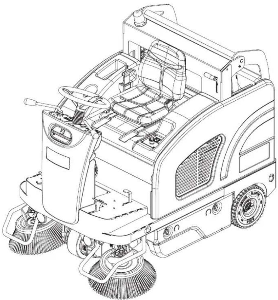
natural_image
Technical line drawing of a cleaning or cleaning utility vehicle with visible brushwork and control panel (no text or symbols)

Model:
9084401010, 9084402010
9084405010, 9084406010
Сертификат за съответствие Osvědčení o shodě Konformitätserklärung Overensstemmelsescertifi kat Declaración de conformidad Vastavussertifi kaat Déclaration de conformité Yhdenmukaisuustodistus Conformity certifi cate
Πιστοποιητικό συμμόρφωσης Megfelelősségi nyilatkozat Potvrda sukladnosti Dichiarazione di conformità Atitikties deklaracija Atbilstības deklarācija Konformitetssertifi sering Conformiteitsverklaring Declaração de conformidade
Deklaracja zgodności Certifi cat de conformitate Заявление о соответствии Överensstämmelsecertifi kat Certifi kát súladu Certifi kat o ustreznosti Uyumluluk sertifi kasi
CE
Модел / Model / Modell / Model / Modelo / Mudel / Modèle / Malli / Model / Movtélo / Modell / Model / Modello / Modelis / Modelis / Modell / Model / Modelo / Model / Model / Модель / Modell / Model / Model / Model :
SW4000 P / LPG, FLOORTEC R 870 P / LPG
Тип / Тур / Тур / Type / Tipo / Tüüp / Type / Tyuppi / Type / Túpoç / Tipus / Vrsta / Tipo / Tipas / Tips / Type / Type / Tipo / Typ / Tip / Typ / Typ / Typ / Tip :
SWEEPER
Сериен номер / Výrobní číslo / Seriennummer / Serienummer / Número de serie / Seerianumber / Numéro de série / Sarjanumero / Serial number / Σειριακός αριθμός / Sorozatszám / Serijski broj / Numero di serie / Serijos numeris / Sērijas numurs / Serienummer / Serienummer / Número de série / Numer seryjny / Numär de serie / Серийный номер / Serienummer / Výrobné číslo / Serijska številka / Seri Numarası :
Година на производство / Rok výroby / Baujahr / Fabrikationsår / Año de fabricación / Väljalaskeaasta / Année de fabrication / Valmistusvuosi / Year of construction / Έτος κατασκευής / Gyártási év / Godina izgradnje / Anno di costruzione / Pagaminimo metai / Izgatavošanas gads / Byggeår / Bauwjaar / Ano de fabrico / Rok produkcji / Anul fabricației / Год выпуска / Tillverkningsår / Rok výroby / Leto izdelave / Leto izdelave/lmal yili :
P100611
P100611
BEDIENPULT UND BEDIENELEMENTE
61. Zündschlüssel:
P100769

P100596
Abbildung 8

P100598
Abbildung 10
Abbildung 13
P100601
Abbildung 19
P100648
ÖLSTAND DER HYDRAULISCHEN HUBANLAGE DES ABFALLBEHÄLTERS ÜBERPRÜFEN

ACHTUNG!
Abbildung 20
P100607
KONTROLLE/REINIGUNG DER LUFTFILTER DES MOTORS

HINWEIS
Abbildung 21
P100615
Abbildung 25
P100619
Abbildung 26

P100610P-GPL
Abbildung 27
CONSERVATION DU MANUEL....2
DÉCLARATION DE CONFORMITÉ 2
DONNÉES D'IDENTIFICATION 2
AUTRES MANUELS DE RÉFÉRENCE....2
PIÈCES DE RECHANGE ET ENTRETIEN 2
MODIFICATIONS ET AMÉLIORATIONS....3
CAPACITÉS OPÉRATIONNELLES....3
CONVENTIONS 3
DÉBALLAGE / LIVRAISON....3
SÉCURITÉ 3
SYMBOLES VISIBLES SUR LA MACHINE....3
SYMBOLES UTILISÉS DANS LE MANUEL....4
INSTRUCTIONS GÉNÉRALES 4
DESCRIPTION DE LA MACHINE ....7
STRUCTURE DE LA MACHINE....7
TABLEAU DE BORD ET COMMANDES....10
ACCESSOIRES / OPTIONS....11
CARACTÉRISTIQUES TECHNIQUES....11
SCHÉMA ÉLECTRIQUE....13
UTILISATION 15
CARBURANT....15
AVANT LA MISE EN MARCHE 16
MISE EN MARCHE ET ARRÊT DE LA MACHINE 16
AFFICHEUR 17
FREIN DE STATIONNEMENT....17
MACHINE AU TRAVAIL 18
VIDANGE DU CONTENEUR DÉCHETS 18
APRÈS L'UTILISATION DE LA MACHINE 19
INACTIVITÉ PROLONGÉE DE LA MACHINE 19
PREMIÈRE PÉRIODE D'UTILISATION....19
ENTRETIEN 20
PLAN D'ENTRETIEN PROGRAMMÉ....20
CONTRÔLE ET RÉGLAGE DU CÂBLE DE FREIN 22
CONTRÔLE ET RÉGLAGE DE LA HAUTEUR DU BALAI CENTRAL 23
REMPLACEMENT DU BALAI CENTRAL 24
CONTRÔLE ET RÉGLAGE DE LA HAUTEUR DES BALAIS LATÉRAUX....25
REMPLACEMENT DES BALAIS LATÉRAUX 26
NETTOYAGE ET CONTRÔLE DE L'INTÉGRITÉ DU FILTRE À POUSSIÈRE EN PANNEAU 27
CONTRÔLE DE LA HAUTEUR ET DU FONCTIONNEMENT DES VOLETS 28
NETTOYAGE DU FILTRE À EAU DU SYSTÈME D'ABATTAGE DES POUSSIÈRES DUSTGUARD™ (OPTIONNEL)....29
CONTRÔLE DU NIVEAU D'HUILE DU SYSTÈME HYDRAULIQUE DE SOULÈVEMENT DU CONTENEUR DÉCHETS......29
CONTRÔLE / NETTOYAGE DES FILTRES À AIR DU MOTEUR....30
CONTRÔLE DU NIVEAU D'HUILE MOTEUR....31
REMPLACEMENT DE L'HUILE MOTEUR 31
CONSERVATION DU MANUEL
DÉCLARATION DE CONFORMITÉ
STRUCTURE DE LA MACHINE
STRUCTURE DE LA MACHINE (suite)
P100611
STRUCTURE DE LA MACHINE (suite)
P100611
TABLEAU DE BORD ET COMMANDES
ACCESSOIRES / OPTIONS
P100769
Figure 3

REPLACEMENT DU BALAI CENTRAL

ATTENTION!
P100596
Figure 8
P100598
Figure 10
REEMPLACEMENT DES BALAIS LATÉRAUX

ATTENTION!
Figure 11
P100599
NETTOYAGE ET CONTRÔLE DE L'INTÉGRITÉ DU FILTRE À POUSSIÈRE EN PANNEAU
Figure 13
P100601
CONTRÔLE DE LA HAUTEUR ET DU FONCTIONNEMENT DES VOLETS
Figure 20
Figure 21
P100615
CONTRÔLE DU NIVEAU D'HUILE MOTEUR

AVERTISSEMENT!
Figure 25
P100619
CONTRÔLE / REMPLACEMENT / RÉTABLISSEMENT DES FUSIBLES
Figure 26

P100610P-GPL
Figure 27
FONCTIONS DE SÉCURITÉ
MANUAL PURPOSE AND CONTENTS 2
TARGET 2
HOW TO KEEP THIS MANUAL....2
DECLARATION OF CONFORMITY 2
IDENTIFICATION DATA....2
OTHER REFERENCE MANUALS....2
SPARE PARTS AND MAINTENANCE....2
CHANGES AND IMPROVEMENTS 3
VISIBLE SYMBOLS ON THE MACHINE....3
SYMBOLS THAT APPEAR ON THIS MANUAL....4
GENERAL INSTRUCTIONS 4
MACHINE DESCRIPTION 7
MACHINE STRUCTURE 7
CONTROL PANEL 10
ACCESSORIES/OPTIONS....11
TECHNICAL DATA....11
WIRING DIAGRAM....13
USE 15
FUEL....15
BEFORE MACHINE START-UP 16
STARTING AND STOPPING THE MACHINE 16
DISPLAY 17
PARKING BRAKE....17
AFTER USING THE MACHINE....19
MACHINE LONG INACTIVITY 19
FIRST PERIOD OF USE 19
MAINTENANCE 20
SCHEDULED MAINTENANCE TABLE 20
BRAKE CABLE CHECK AND ADJUSTMENT 22
MAIN BROOM HEIGHT CHECK AND ADJUSTMENT 23
MAIN BROOM REPLACEMENT 24
SIDE BROOM HEIGHT CHECK AND ADJUSTMENT 25
SIDE BROOM REPLACEMENT 26
PANEL DUST FILTER CLEANING AND INTEGRITY CHECK 27
DUSTGUARD™ SYSTEM WATER FILTER CLEANING (OPTIONAL) 29
HOPPER HYDRAULIC LIFTING SYSTEM OIL LEVEL CHECK 29
ENGINE AIR FILTER CHECK/CLEANING 30
ENGINE OIL LEVEL CHECK....31
ENGINE OIL CHANGE 31
ENGINE FILTER TRAP CLEANING (for Petrol version) 32
ENGINE SPARK PLUG CHECK/REPLACEMENT 32
ENGINE BAFFLE PLATE CLEANING 33
FUSE CHECK/REPLACEMENT/RESET 34
SAFETY FUNCTIONS 34
EMERGENCY PUSH-BUTTON 34
DRIVER'S SEAT MICROSWITCH....34
HOPPER POSITION SENSOR 34
HOPPER SAFETY VALVE 34
TROUBLESHOOTING 35
SCRAPPING 36
INTRODUCTION

NOTE
The numbers in brackets refer to the components shown in Machine Description chapter.
MANUAL PURPOSE AND CONTENTS
The purpose of this Manual is to provide the operator with all necessary information to use the machine properly, in a safe and autonomous way. It contains information about technical data, safety, operation, storage, maintenance, spare parts and disposal. Before performing any procedure on the machine, the operators and qualified technicians must read this Manual carefully. Contact Nilfisk in case of doubts concerning the interpretation of the instructions and for any further information.
TARGET
This Manual is intended for operators and technicians qualified to perform the machine maintenance.
The operators must not perform procedures reserved for qualified technicians. Nilfisk will not be responsible for damages coming from failure to follow these instructions.
HOW TO KEEP THIS MANUAL
The Instructions for Use Manual must be kept near the machine, inside an adequate case, away from liquids and other substances that can cause damage to it.
DECLARATION OF CONFORMITY
The Declaration of Conformity, supplied with the machine, certifies the machine conformity with the law in force.

NOTE
Two copies of the original declaration of conformity are provided together with the machine documentation.
IDENTIFICATION DATA
The machine serial number and model name are marked on the plate (30).
Product code and year of production are marked on the same plate (Date code: A17, means January 2017).
The engine model and serial number are shown on the plate (59).
This information is useful when ordering machine and engine spare parts. Use the following table to write down the machine and engine identification data for any further reference.
MACHINE model ....
PRODUCT code ....
MACHINE serial number ....
ENGINE model
ENGINE serial number ....
OTHER REFERENCE MANUALS
- Engine Manual, supplied with the machine (to be considered an integral part of this Manual).
Moreover, the following Manuals are available:
– Spare Parts List (supplied with the machine)
– Service Manual (that can be consulted at Nilfisk Service Centers)
SPARE PARTS AND MAINTENANCE
All necessary operating, maintenance and repair procedures must be performed by qualified personnel or by Nilfisk Service Centers. Only original spare parts and accessories must be used.
Contact Nilfisk for service or to order spare parts and accessories, specifying the machine model, product code and serial number.
CHANGES AND IMPROVEMENTS
Nilfisk constantly improves its products and reserves the right to make changes and improvements at its discretion without being obliged to apply such benefits to the machines that were previously sold.
Any change and/or addition of accessory must be approved and performed by Nilfisk.
This sweeper has been approved to clean (sweeping and vacuuming) compact and solid floors, in commercial and industrial environments, under safe operation conditions by a qualified operator.
CONVENTIONS
Forward, backward, front, rear, left or right are intended with reference to the operator's position, that is to say on the driver's seat (3).
UNPACKING/DELIVERY

CAUTION!
To unpack the machine, carefully follow the instructions on the packing.
Upon delivery carefully check that the machine and its packing have not been damaged during transportation. In case of visible damages, keep the packing and have it checked by the carrier that delivered it. Call the carrier immediately to fill in a damage claim. Check that the machine is equipped with the following features:
- Technical documents:
- Sweeper Instructions for Use Manual
• Engine Manual (Honda GX-200) - Sweeper Spare Parts List
- No. 1 10 A fuse
- No. 1 70 A fuse
SAFETY
The following symbols indicate potentially dangerous situations. Always read this information carefully and take all necessary precautions to safeguard people and property.
The operator's cooperation is essential in order to prevent injury. No accident prevention program is effective without the total cooperation of the person responsible for the machine operation. Most of the accidents that may occur in a factory, while working or moving around, are caused by failure to comply with the simplest rules for exercising prudence. A careful and prudent operator is the best guarantee against accidents and is essential for successful completion of any prevention program.
VISIBLE SYMBOLS ON THE MACHINE

WARNING!
Carefully read all the instructions before performing any operation on the machine.

WARNING!
Hot parts, danger of burns.

DANGER!
Internal combustion engine. Do not inhale exhaust gas fumes. Carbon monoxide (CO) can cause brain damage or death.

WARNING!
Moving parts.

WARNING!
Do not wash the machine with direct or pressurised water jets.

WARNING!
Moving parts. Danger of crushing.

WARNING!
Do not use the machine on slopes with a gradient exceeding the specifications.
WARNING!
Parts under voltage. Presence of corrosive fluids.
SYMBOLS THAT APPEAR ON THIS MANUAL

DANGER!
It indicates a dangerous situation with risk of death for the operator.

WARNING!
It indicates a potential risk of injury for people or damage to objects.

CAUTION!
It indicates a caution or a remark related to important or useful functions. Pay careful attention to the paragraphs marked by this symbol.

NOTE
It indicates a remark related to important or useful functions.

CONSULTATION
It indicates the necessity to refer to the Instructions for use Manual before performing any procedure.
GENERAL INSTRUCTIONS
Specific warnings and cautions to inform about potential damages to people and machine are shown below.

DANGER!


- Carbon monoxide (CO) can cause brain damage or death.
- The internal combustion engine of this machine can emit carbon monoxide.
- Do not inhale exhaust gas fumes.
- Only use indoors when adequate ventilation is provided, and with the help of an assistant who can monitor the operator's health.

DANGER!
Before performing any maintenance, repair, cleaning or replacement procedure disconnect the battery connector, remove the ignition key and engage the parking brake.
- This machine must be used by properly trained operators only.
- Sharp turns must be made at slowest possible speed. Avoid abrupt turns, particularly on slopes, and turns with the hopper lifted.
- Do not lift the hopper when the machine is on a slope.
- Keep the batteries away from sparks, flames and incandescent material. During the normal operation explosive gases are released.
- Do not wear jewels when working near electrical components.
- Do not work under the lifted machine without supporting it with safety stands.
- When working under the open hood, ensure that it cannot be closed by accident.
- Do not operate the machine near toxic, dangerous, flammable and/or explosive powders, liquids or vapours: This machine is not suitable for collecting dangerous powders.
- Be careful: fuel is highly flammable.

DANGER!
- Do not smoke or bring naked flames in the area where the machine is refuelled or where the fuel is stored.
- Refuel outdoors or in a well-ventilated area, with the engine off.
– Turn off the engine and let it cool down for a few minutes, then remove the fuel tank plug.
– Leave at least a space of 4 cm in the filler to allow the fuel to expand.
After refuelling, check that the fuel tank cap is firmly closed.
- If any fuel is spilled while refuelling, clean the tank area and allow the vapours to evaporate before starting the engine.
- Do not let fuel come into contact with the skin; do not breathe fuel vapours. Keep out of reach of children.
- Do not tilt the engine or the machine too much to avoid fuel spillage.
- When moving the machine, the fuel tank must not be full and the fuel valve must be closed.
- Do not lay any object on the engine.
- Stop the engine before performing any procedure on it. To avoid any incidental start, disconnect the spark plug cap or disconnect the battery negative terminal.
- See also the SAFETY RULES in the Engine Manual, which is to be considered an integral part of this Manual.
- Lead batteries (WET) are installed on this machine, do not tilt the machine more than 30^ from its horizontal position to prevent the highly corrosive acid to leak out of the batteries. When the machine is to be tilted to perform maintenance procedures, remove the batteries.
- (For LPG version). Do not use the machine in case of gas leaks. Disconnect the fuel hose and replace the LPG tank. If the gas leak persists, disconnect the fuel hose and contact the Nilfisk Service Center.
- Carefully read all the instructions before performing any maintenance/repair procedure.
- When working near the hydraulic system, always wear protective clothes and safety glasses.
- This machine is not intended for use by persons (including children) with reduced physical, sensory or mental capabilities, or lack of experience and knowledge, unless they have been given supervision or instruction concerning use of the machine by a person responsible for they safety. Children should be supervised to ensure that they do not play with the machine.
- Close attention is necessary when used near children.
– Use only as shown in this Manual. Use only Nilfisk recommended accessories.
- Check the machine carefully before each use, always check that all the components have been assembled before use. If the machine is not perfectly assembled it can cause damages to people and properties.
Take all necessary precautions to prevent hair, jewels and loose clothes from being caught by the machine moving parts.
- To avoid any unauthorised use of the machine, remove the ignition key.
- Do not leave the machine unattended without being sure that it cannot move independently.
- Do not use the machine on slopes with a gradient exceeding the specifications.
- Do not tilt the machine more than the angle indicated on the machine itself, in order to prevent instability.
- Use only brooms supplied with the machine or those specified in the Instructions for Use Manual. Using other brooms could reduce safety.
– Before using the machine, close all doors and/or covers as shown in the Instructions for Use Manual.
- Do not wash the machine with direct or pressurised water jets, or with corrosive substances.
- Use the machine only where a proper lighting is provided.
- Working lights (optional) have to be used only to enhance visibility on the floor to be cleaned, but they do not authorize anyone to use the sweeper in dark environments.
– While using this machine, take care not to cause damage to people or objects.
- Do not bump into shelves or scaffoldings, especially where there is a risk of falling objects.
- Do not lean liquid containers on the machine, use the relevant can holder.

WARNING!
- The storage temperature must be between 0^ and +40^ .
- The machine working temperature must be between 0^ and +40^ .
-
The humidity must be between 30% and 95% .
-
Always protect the machine against the sun, rain and bad weather, both under operation and inactivity condition. Store the machine indoor, in a dry environment: this machine must be used in dry conditions, it must not be used or kept outdoors in wet conditions.
- Do not use the machine as a means of transport, or for pushing/towing.
- The machine maximum capacity, operator's weight not included, is 100 kg (the weight of waste).
– In case of fire, use a powder fire extinguisher, not a water one.
- Adjust the operation speed to suit the floor conditions.
- Avoid sudden stops when the machine is going downhill. Avoid sharp turns. Drive at slow speed when going downhill.
- This machine cannot be used on roads or public streets.
- Do not tamper with the machine safety guards.
– Follow the routine maintenance procedures scrupulously.
- Do not allow any object to enter into the openings. Do not use the machine if the openings are clogged. Always keep the openings free from dust, hairs and any other foreign material which could reduce the air flow.
(Only for versions equipped with DustGuard™ system). Pay attention during machine transportation when temperature is below freezing point. The water in the tank or in the hoses could freeze and seriously damage the machine.
- Do not remove or modify the plates affixed to the machine.
- When the machine is to be pushed for service reasons (lack of fuel, engine break-down, etc.), the speed must not exceed 4 km/h.
In case of machine malfunctions, ensure that these are not due to lack of maintenance. If necessary, request assistance from the authorised personnel or from an authorised Service Center.
- If parts must be replaced, require ORIGINAL spare parts from an Authorised Dealer or Retailer.
- To ensure machine proper and safe operation, the scheduled maintenance shown in the relevant chapter of this Manual, must be performed by the authorised personnel or by an authorised Service Center.
- The machine must be disposed of properly, because of the presence of toxic-harmful materials (batteries, oils, etc.), which are subject to standards that require disposal in special centres (see the Scrapping chapter).
- While the engine is running, the silencer warms up; do not touch the silencer when it is hot to avoid burns or fires.
- Running the engine with an insufficient quantity of oil can seriously damage the engine. Check the oil level with the engine off and the machine on a level surface.
– Never run the engine if the air filter is not installed, because the engine could be damaged.
- Technical service procedures on the engine must be performed by an authorised Dealer.
Only use original spare parts or parts of matching quality for the engine. Using spare parts of lower quality can seriously damage the engine.
- See also the SAFETY RULES in the Engine Manual, which is to be considered an integral part of this Manual.
Guide lines to bacteria control and other dangers coming from the presence of microbes in the DustGuard™ system (optional).

WARNING!
To prevent the operators and other people from developing infections caused by microbes and Legionella that may flourish in the dust guard system, take the following precautions:
If possible, fill the tank with cold water (< 20 °C).
- DO NOT use stagnant water to fill the tank.
— DO NOT use recycled water, undrinkable water or water that has been in contact with the soil.
- Adjust and turn the nozzles towards the floor only, from preventing possible inhaling.
- Do not store the machine outdoors or near sources of heat.
- Do not over-fill the tank. Fill the tank sufficiently so that it can be emptied by using the system.
– Empty the tank every 10 hours or once a week, according to the use.
– If the machine is not used for more than one week, empty the tank completely, and let it dry.
- If the tank cannot be cleaned regularly, consider using a biocide that can kill or exert a controlling effect on Legionella bacteria. Biocide must be chosen according to the local regulations and must be used according to the relevant instructions and cautions, to avoid that the personnel gets affected by dangerous chemical substances.
- If chemical products have to be used in the water tank, it is mandatory to apply the relevant information and caution labels of the product.
MACHINE DESCRIPTION
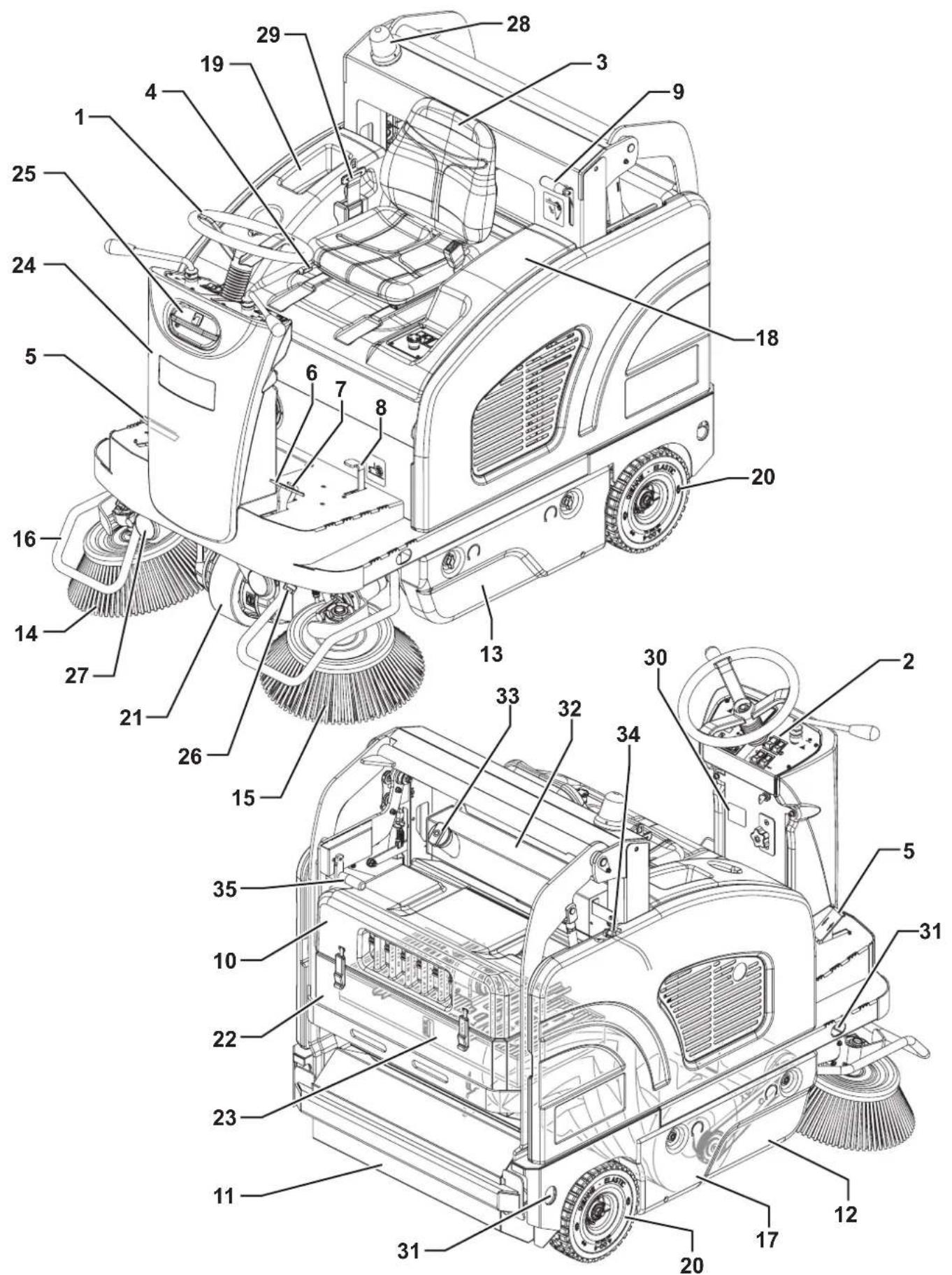
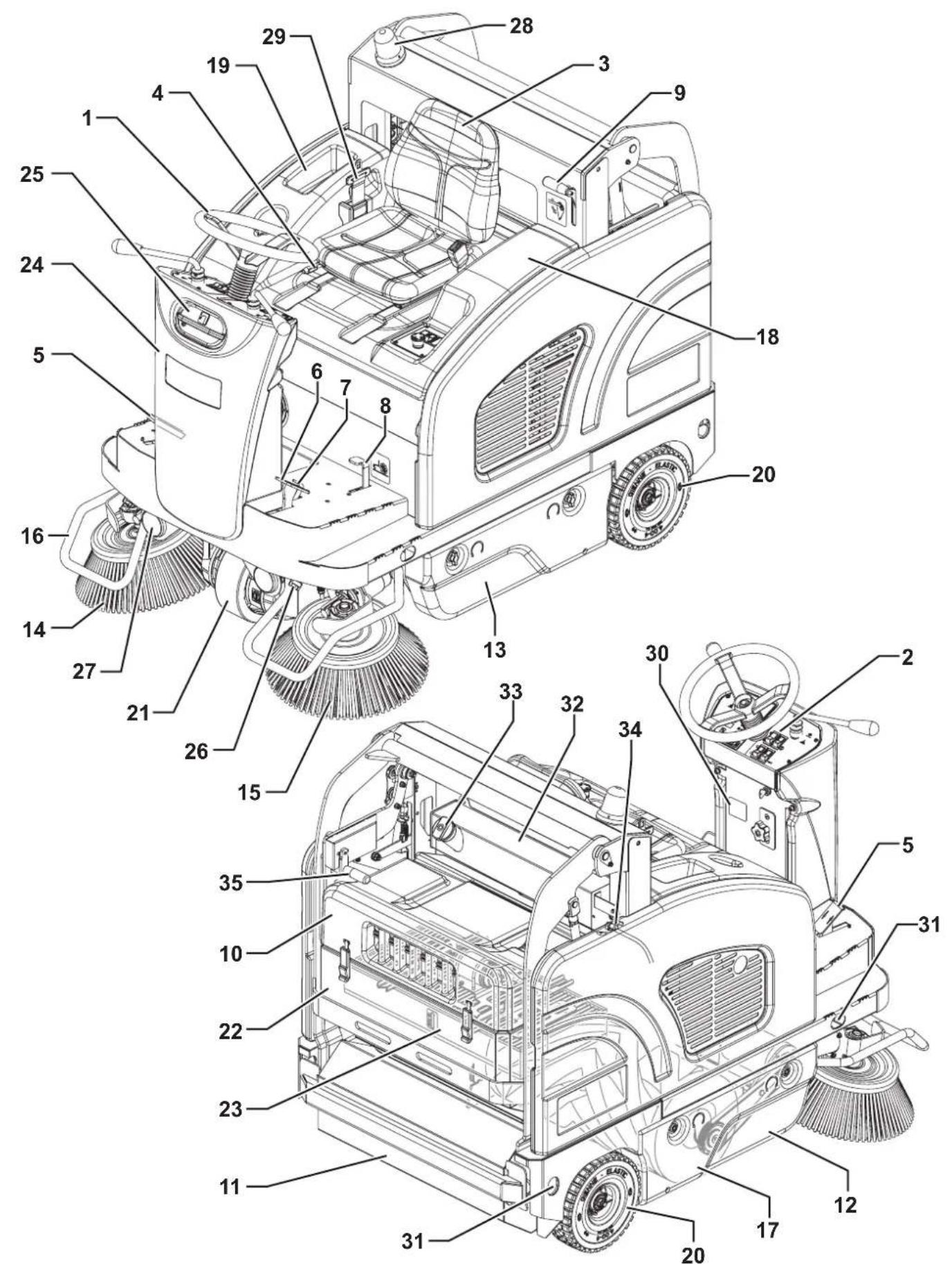
MACHINE STRUCTURE
-
Steering wheel
-
Control panel (see the following paragraph)
-
Driver's seat with safety microswitch
-
Seat position adjusting lever
-
Drive pedal
-
Service brake pedal
-
Parking brake lever: press both the service brake (6) and the lever (7) to switch from the service brake to the parking brake
-
Front skirt lifting pedal
-
Release lever for hopper discharge
-
Rear hood with vacuum system
-
Hopper (empty it when it is full)
-
Right door (to be opened for performing maintenance procedures only)
-
Left door (for main broom removal)
-
Right side broom
-
Left side broom (optional)
-
Side broom guards (optional)
-
Main broom
-
Engine compartment hood
-
Can holder
-
Rear wheels
-
Front driving and steering wheel
-
Dust filter container
-
Panel filter with filter-shaker
-
Steering column or water tank for dust guard system (optional)
-
Dust guard system water filler neck plug (optional)
-
Dust guard system nozzles (optional)
-
Working lights (optional)
-
Flashing light (always on when the ignition key is turned to "I")
-
Safety belt (optional)
-
Serial number/technical data/conformity certification plate
-
Anchoring slots for transport (not for lifting)
-
Fuel tank (Petrol)
-
Filler plug (Petrol)
-
Fuel opening/closing valve (Petrol)
-
Hopper manual returning handle
MACHINE STRUCTURE (Continues)
P100611
MACHINE STRUCTURE (Continues)
- Engine compartment hood lifting handle
- Engine
- Dynamotor
- Battery connection diagrams
- Right side panel
- Batteries
- Right side broom motor resettable thermal fuse
- Left side broom motor resettable thermal fuse (optional)
-
Lamellar fuse box
-
Electrical component box
- Drive system electronic board
- Hydraulic unit with tank for hopper lifting
- Open hood safety rod
- Vacuum system motor connector
- Choke lever
- LPG tank (LPG version)
- LPG tank fastening band (LPG version)
- Solenoid valve with adjuster (LPG version)
- Engine serial number and model plate
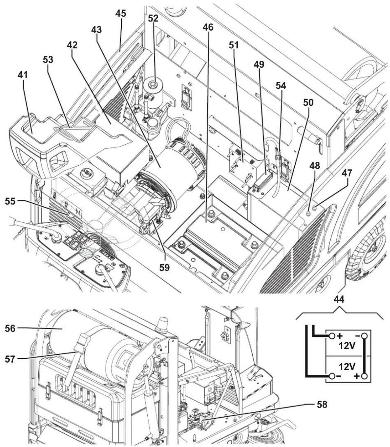
P100611
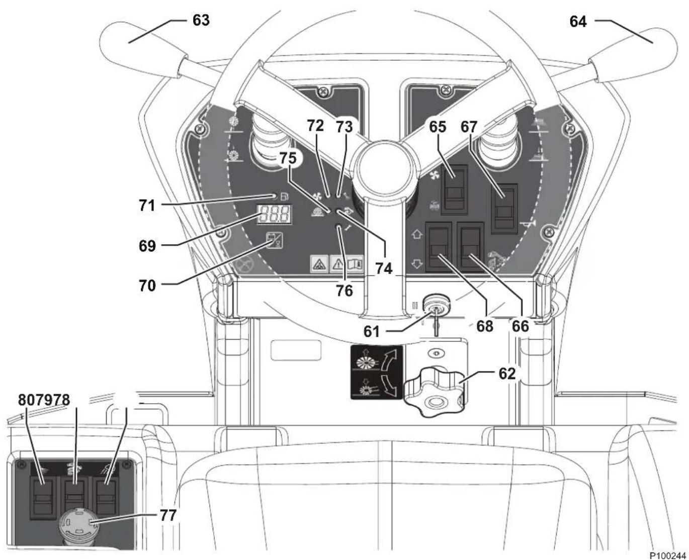
CONTROL PANEL
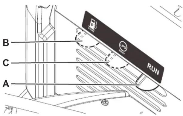
61. Ignition key:
- When turned to "0", it turns the electrical system off and disables all machine functions
- When turned to "I", it enables the machines functions
- When turned to "II" it starts the engine. When the dynamotor starts, release the key, which will return to "I"
62. Main broom height adjusting knob:
- Turn it counter-clockwise to increase the broom pressure on the floor
- Turn it clockwise to decrease the broom pressure on the floor
63. Main broom lifting/lowering lever
64. Side broom lifting/lowering lever
65. Switch for:
• Vacuum system activation/deactivation (upper part)
• Filter shaker activation (lower part)
66. Hopper movement enabling switch
67. Horn switch
68. Forward/reverse gear switch
69. Display
- Display switch for selecting the following functions:
- Working hours
- Battery voltage (V)
71. Fuel reserve warning light (yellow)
72. Vacuum system warning light (green)
73. Dust guard system (optional) warning light (green)
74. Hopper lifting system warning light (yellow)
75. Main broom overpressure warning light (red)
76. Drive system malfunction warning light (red)
77. Emergency push-button. Press it in case of emergency to stop all the machine functions. To deactivate the emergency push-button, turn it in the direction shown by the arrow.
78. Working light switch (optional)
79. Hopper lifting/lowering switch
80. Dust guard system switch (optional)
ACCESSORIES/OPTIONS
In addition to the standard components, the machine can be equipped with the following accessories/options, according to the machine specific use:
- Left side broom
- Right and left armrests
- Main and side brooms with harder or softer bristles
- Non-marking wheels
– Paper dust filter (standard for FLOORTEC R 870) – FOPS protective roof - Non-marking skirts
- Roof cover
- Working lights
- Side broom guards
- Safety belts
- DustGuard™ system
For further information concerning the optional accessories, contact an authorised Retailer.
TECHNICAL DATA
| Model SW4000 P | FLOORTEC R 870 P | SW4000 LP FLOORTEC R 870 LP | |
| Cleaning width with one side broom 975 mm | |||
| with two side brooms 1,250 mm | |||
| Main broom size (length x diameter) 700 x 340 mm | |||
| Side broom diameter 450 mm | |||
| Theoretical working capacity main broom 4,900 m | ^2/h | ||
| with one side broom 6,825 m | ^2/h | ||
| with two side brooms 8,750 m | ^2/h | ||
| Hopper | capacity | 75 litres | |
| maximum liftable weight | 100 kg | ||
| maximum lifting height | 1,590 mm | ||
| Filter | cleaning system | Electrical filter shaker | |
| area | 7 m^2 | ||
| filtering capacity | 4 μm | ||
| Power | 4.1 kW (5.5 hp) @ 3,600 rpm | ||
| Engine model | Honda GX-200 | ||
| Fuel tank capacity | 7.8 litres | 15 Kg | |
| Main broom | motor power | 600 W | |
| speed | 550 rpm | ||
| Side broom | motor power | 90 W | |
| speed | 110 rpm | ||
| Vacuum | motor power | 260 W | |
| Drive | type | Electric drive on front wheel | |
| gearmotor power | 1,000 W | ||
| forward speed | 7 km/h | ||
| reverse speed | 4.5 km/h | ||
| Maximum gradient when working | 20 % | ||
| Hopper hydraulic control unit | 250 W | ||
| Filter shaker motor | 90 W | ||
| Total absorbed power | 2.0 kW | ||
| Working autonomy | 13 h | 25 h | |
| Dimensions(length x width x height) | machine body | 1,640 x 1,035 x 1,330 mm | |
| machine with side brooms | 1,640 x 1,050 x 1,330 mm | ||
| machine with flashing light | 1,640 x 1,035 x 1,390 mm | ||
| machine with FOPS protective roof (optional) | 1,640 x 1,035 x 1,990 mm | ||
| battery compartment | 360 x 380 x 220 mm | ||
| LPG tank maximum size (length x diameter) | - | 720 x 300 mm | |
TECHNICAL DATA (Continues)
| Model SW4000 P | FLOORTEC R 870 P | SW4000 LP FLOORTEC R 870 LP | |
| Weight kerb weight 511 Kg 515 Kg | |||
| total kerb weight (*) 594 Kg 622 Kg | |||
| front axle kerb weight (*) 251 Kg 254 Kg | |||
| rear axle kerb weight (*) 343 Kg 368 Kg | |||
| gross vehicle weight (GVW) 775 Kg 803 Kg | |||
| Wheel specific pressure on the floor (front - rear wheels, in running conditions) 0.8 - 0.2 N/mm | ^2 | ||
| Sound pressure level at workstation (ISO 11201, ISO 4871, EN 60335-2-72) (LpA) | 75 dB(A) ± 3 dB(A) | ||
| Machine sound pressure level (ISO 3744, ISO 4871, EN 60335-2-72) (LwA) 94 dB(A) | |||
| IP protection class | X3 | ||
| Dust guard system water tank (optional) capacity | 20 litres | ||
| U-turn space (right - left) | 1,920 - 1,890 mm | ||
| Vibration level at the operator's arms (ISO 5349-1) (**) | < 2.5 m/s ^2 | ||
| Vibration level at the operator's body (ISO 2631-1) (**) | < 0.9 m/s ^2 | ||
(*) With operator on board, fuel tank and hopper empty.
(**) Under normal working conditions, on a level asphalt surface.
Machine Material Composition and Recyclability
| Type | Recyclable percentage | SW4000 P FLOORTEC R 870 P weight percentage | SW4000 LP FLOORTEC R 870 LP weight percentage |
| Aluminium | 100 % | 0.0 % | 0.0 % |
| Electric motors - various | 29 % | 21.1 % 21.1 % | |
| Ferrous materials | 100 % | 48.3 % 48.8 % | |
| Wiring harnesses | 80 % | 0.8 % | 0.8 % |
| Liquids | 100 % | 0.5 % | 0.5 % |
| Plastic - non-recyclable material | 0 % | 0.9 % | 0.8 % |
| Plastic - recyclable material | 100 % | 8.6 % | 8.4 % |
| Polyethylene | 92 % | 6.0 % | 5.9 % |
| Rubber | 20 % | 3.5 % | 3.5 % |
| Cardboard - paper - wood | 100 % | 10.3 % 10.2 % |
Hydraulic oil technical data
| Viscosity at 40 °C | mm ^2 /s | 45 | 32 |
| Viscosity at 100 °C | mm ^2 /s | 7.97 | 6.40 |
| Viscosity index | / | 150 | 157 |
| Flash point COC | °C | 215 | 202 |
| Pour point | °C | -36 | -36 |
| Density at 15 °C | kg/l | 0.87 | 0.865 |

CAUTION!
If the machine is to be used at ambient temperatures below +10 °C, the oil should be changed with equivalent oil having a viscosity of 32 cSt. For temperatures below 0 °C, use an oil with lower viscosity.
WIRING DIAGRAM
Key
| BAT 24 | V batteries |
| BZ1 | Reverse gear buzzer |
| BE | Flashing light |
| D1 | Diode electronic board |
| D2, D3 | Diode |
| EB1 | Drive system electronic board |
| EB2 | Dashboard electronic board |
| ES0 | Line electromagnetic switch |
| ES1 | Main broom electromagnetic switch |
| ES2 | Engine start electromagnetic switch |
| EV1 | LPG safety solenoid valve |
| FA | Main broom fuse (50 A) |
| FC | Battery charge fuse (80 A) |
| F0 | Main fuse (150 A) |
| F1 | Vacuum system fuse (30 A) |
| F2 | Filter shaker fuse (30 A) |
| F3 | Display electronic board (3 A) |
| F4 | Key circuit fuse (10 A) |
| F5 | Dust guard system pump fuse (5 A) (optional) |
| F6 | Hopper pump fuse (30 A) |
| FR1 | Right side broom circuit breaker (15 A) |
| FR2 | Left side broom circuit breaker (15 A) (optional) |
| FR | Engine frame |
| HN | Horn |
| K1 | Vacuum system relay |
| K2 | Filter shaker relay |
| K3A+,- | Hopper lifting relay |
| K3B+,- | Hopper lowering relay |
| K4 | Machine on relay |
| K5 | Side broom relay |
| K6 | Dust guard system pump relay (optional) |
| KT1 | LPG safety timer relay |
| L1, L2 | Working lights (optional) |
| M0 | Driving wheel |
| M1 | Vacuum system motor |
| M2 | Filter shaker motor |
| M3 | Hopper pump motor |
| M4 | Main broom motor |
| M5 | Dynamotor |
| M6 | Right side broom motor |
| M7 | Left side broom motor |
| M8 | Dust guard system pump motor (optional) |
| R1 | Drive pedal |
| S1 | Hopper lifting sensor |
| S2 | Main broom lever sensor |
| S3 | Side broom lever sensor |
| S4 | Fuel reserve sensor |
| SPK | Engine spark plug |
| SW0 | Emergency push-button |
| SW1 | Ignition key |
| SW2 | Forward/reverse gear switch (built in the pedal) |
| SW3 | Filter shaker/vacuum system switch |
| SW4 | Hopper enabling switch |
| SW5 | Hopper lifting/lowering switch |
| SW6 | Horn switch |
| SW7 | Driver's seat safety microswitch |
| SW8 | Dust guard system switch (optional) |
| SW9 | Working light switch (optional) |
Colour codes
| BK Black | |
| BU Blue | |
| BN Brown | |
| GN | Green |
| GY Grey | |
| OG | Orange |
| PK Pink | |
| RD Red | |
| VT Violet | |
| WH | White |
| YE Yellow | |
WIRING DIAGRAM (Continues)
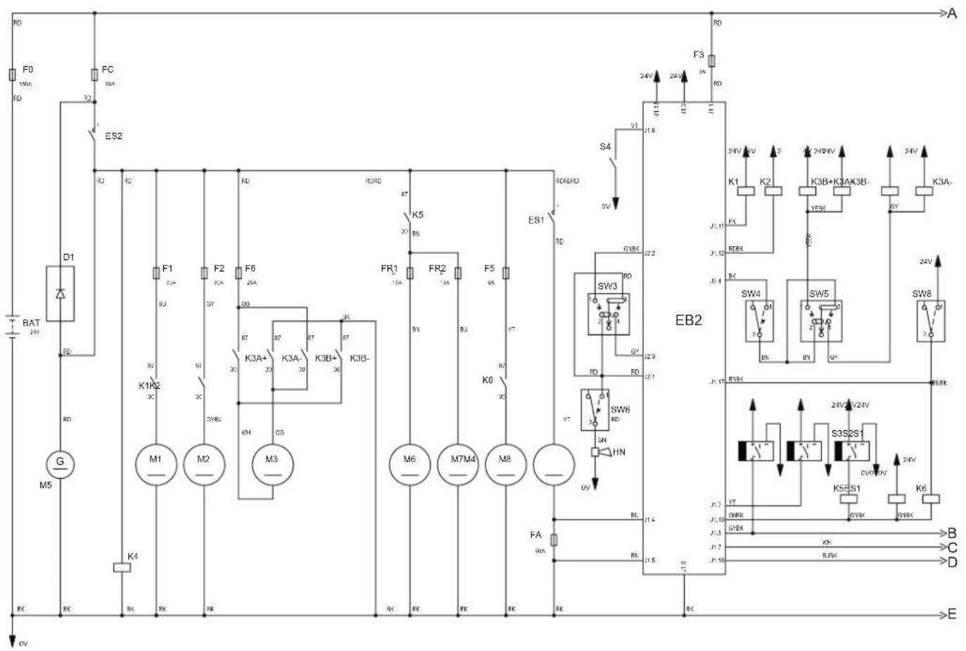
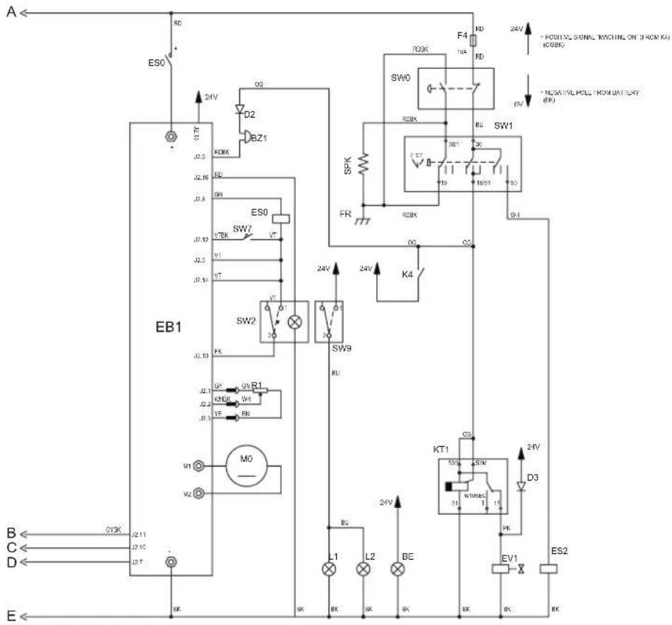
P100614
USE

WARNING!
On some points of the machine there are some adhesive plates indicating:
- DANGER
- WARNING
- CAUTION
- CONSULTATION
While reading this Manual, the operator must pay particular attention to the symbols shown on the plates (see the Visible Symbols On The Machine paragraph).
Do not cover these plates for any reason and immediately replace them if they are damaged.
If the machine has not been used after being transported, check that all the blocks have been removed.
FUEL

DANGER!


- Carbon monoxide (CO) can cause brain damage or death.
– The internal combustion engine of this machine can emit carbon monoxide. - Do not inhale exhaust gas fumes.
- Only use indoors when adequate ventilation is provided, and with the help of an assistant.
Fuel for Petrol version

CAUTION!
- Always stop the engine before filling the fuel tank.
- Do not smoke while filling the fuel tank.
– Fill the fuel tank in a well-ventilated area. - Do not fill the fuel tank near sparks or open flame.
When necessary, unscrew the plug (33) of the fuel tank (32) and refuel. Do not overfill and wipe any fuel accidentally spilled out. Use unleaded fuel having a pump octane number 91 or higher.
Do not use old or contaminated fuel or an oil/fuel mix. Prevent dirt or water from entering the fuel tank.
Supply for LPG version

DANGER!
Before replacing the LPG tank, close the safety valve and disconnect the hose.
Install an LPG tank (56) having characteristics which comply with the laws in force in the country where it is used.
Fasten the tank with a fastening band (57).
Connect the hose and open the cut-off valve on the LPG tank. Always wear gloves when connecting and disconnecting the hose. When the machine is not operating, close the LPG tank safety valve.

NOTE
Place the LPG tank in a proper horizontal position. Connect the hose to the tank and check that there are no gas leaks.

DANGER!
Do not use the machine in case of gas leaks. Disconnect the hose and replace the LPG tank. If the gas leak persists, disconnect the hose and contact the Nilfisk Service Center.
BEFORE MACHINE START-UP
Checklist
- Have a full knowledge of the machine operating controls and their functions.
- Insert the key (61) and start the machine (see the procedure in the following paragraph).
- Check the fuel reserve warning light (71). If it is on, refuel with petrol (Petrol version) or replace the tank (LPG version) (see previous paragraph).
- Check the horn with switch (67), the reverse gear buzzer with switch (68) and the working light switch (78, optional) for proper operation.
- Check the parking brake (7 and 6). The brake must hold its (locked parked) setting firmly without easily being released (report all defects immediately to Nilfisk Service Center).
- Check the service brake pedal (6) for proper operation.

WARNING!
If the pedal is “spongy” or fades under pressure without an efficient braking force, do not drive the machine (report all defects immediately to Nilfisk Service Center).
- Make sure that there are no open doors/hoods and that the machine is in normal operating conditions.
Cleaning planning
- Arrange long runs with a minimum of stopping or starting.
- Allow a small amount of broom path overlap to ensure complete coverage.
- Avoid making sharp turns, bumping or scraping the side of the machine.
Filling the DustGuard™ system water tank (optional)
- Remove the plug (25) to reach the filler neck.
- Fill the tank (24) with clean water. Do not fill the tank completely, leave a few centimetres from the edge.
STARTING AND STOPPING THE MACHINE
Starting the machine
- Sit on the driver's seat (3) and adjust it with the lever (4) to allow easy reach of all controls.

NOTE
The driver's seat (3) is equipped with a safety sensor, which allows the machine to be driven only when the operator is on the driver's seat.
-
Engage the choke lever (A, Fig. 1) in the following positions:
-
(Petrol Version). With cold engine, move the choke lever to position (B) before starting the machine.
-
(LPG version). Always start the machine with the choke lever in position (C).
-
Insert the ignition key (61) and turn it clockwise to "II". When the engine starts, release the key. Wait (a few seconds) for the display (69) to turn on and sowing the working hours.

CAUTION!
When starting the engine do not press the drive pedal (5).
If the drive system warning light (76) flashes, turn off the machine and repeat the start-up procedure.
P100592
Figure 1
- After the ignition, let the engine run for a few seconds, when the engine is warm move the choke lever in position (A, Fig. 1).
- Disengage the parking brake.
- Drive the machine to the working area, by keeping the hands on the steering wheel (1) and pressing the pedal (5). The drive speed can be adjusted from zero to maximum speed by increasing the pressure on the pedal.
- The forward/reverse direction is selected with the relevant switch (68) on the dashboard. When the reverse gear is selected, the relevant buzzer turns on.
- Lower the main broom with the lever (63).
- Lower the side brooms with the lever (64).

NOTE
When the brooms are lowered, the brooms, the vacuum system and the dust guard system (optional - if turned on with the switch (80)) automatically activates only when the machine is moving.
- Start sweeping by driving the machine with the hands on the steering wheel (1) and by pressing the drive pedal (5).

NOTE
The brooms (14, 15 and 17) can be lowered and lifted even when the machine is moving.
The brooms do not turn when they are lifted or when the machine is stationary.
When the machine is stationary, the vacuum system and dust guard system (optional), turn off automatically.

WARNING!
When steering, avoid abrupt direction changes, pay careful attention and drive the machine at slow speed, especially when the hopper is full or when operating on inclines.
Drive the machine slowly on inclines. Use the brake pedal (6) to control machine speed while descending inclines.
Do not turn the machine on an incline; drive straight up or down.
Stopping the machine
- To stop the machine, release the drive pedal (5).
To stop the machine quickly, also press the service brake pedal (6).

WARNING!
Frequent and extended use of the service brake (6), especially on slopes, can cause a rapid wear of the pads.
Keep the braking system in maximum efficiency (see paragraphs Brake Cable Adjustment and Scheduled Maintenance Table in Maintenance chapter).
- In case of emergency, press the emergency push-button (77) to immediately stop the machine.
To deactivate the emergency push-button (77), turn it clockwise.
- Turn the ignition key (61) to "0" and remove it.
DISPLAY
The display (69) shows the machine working hours; the time counted is the one during which the main broom is moving.

NOTE
When the working hour count exceeds 999, hours are then displayed in thousands with two decimal digits (for example 1.23 = 1,230 hours).
By pressing the push-button (70) it is possible to shortly display the battery voltage in Volts, with one decimal digit.
Displayed codes
- If the display (69) repeatedly displays "LOU" code, it means that the batteries could be damaged: therefore, it is necessary to reduce the intensity of work, for example by reducing the ground pressure of the broom, or by avoiding running extensively on slopes.
- If the display (69) repeatedly displays "HIU" code, it means that the battery charge is excessive: this may happen, for example, if the machine is kept for too long with the engine running. In this case, stop the engine when the machine is stationary.
If these problems persist, maybe it is necessary to calibrate the engine rpm. For this operation, contact an authorised Nilfisk Service Center.

CAUTION!
Working for a long time with the above codes displayed can reduce the working life of the batteries.
PARKING BRAKE
- Engage the parking brake by pressing the pedal (6) and engaging the lever (7).
- Disengage the parking brake by pressing and releasing the pedal (6).

WARNING!
Before performing any maintenance, repair, cleaning or replacement procedure engage the parking brake.
Engage the parking brake when parking the machine on a slope.

WARNING!
Before leaving the machine unattained, be sure that the parking brake can stop the machine with a large safety margin.
MACHINE OPERATION
- Drive the machine to the work area as shown in the previous paragraph.
- Lower the main broom with the lever (63), and the side brooms with the lever (64).
- If equipped, turn on the dust guard system with the switch (80).
- Drive the machine straight forward at a quick walking speed. Drive the machine slower when sweeping large amounts of dust or debris or when safe operation dictates slower speeds. Overlap passes 10 cm.
- To collect light and bulky waste materials, lift the front skirt by pressing the pedal (8); take into consideration that the machine vacuum capability is reduced when the front skirt is lifted.

WARNING!
When operating on wet floors, it is essential to turn off the vacuum system by pressing the switch (65) to prevent the dust filter from being damaged.
- For machine proper operation, the dust filter must be as clean as possible. For cleaning it while sweeping, turn on the filter shaker by pressing the lower side of the switch (65). While working, repeat the procedure every 10 minutes on average (depending on the dustiness of the area to be cleaned).

NOTE
This procedure can also be performed when the machine is moving.

CAUTION!
When the dust filter is clogged and/or the hopper is full, the machine cannot collect dust and debris any more.
- The hopper (11) should be dumped after each working period and whenever it is full (see the procedure in the next paragraph).

CAUTION!
The engine is equipped with a warning system to prevent damages to the engine itself in case the oil quantity in the carter is insufficient. Before the oil level goes below the safety limit, the warning system automatically stops the engine.

CAUTION!
If the main broom motor overload warning light (75) flashes repeatedly while sweeping, there may be debris that slows down the broom (for checking this, see the procedure in Main Broom Replacement paragraph, under Maintenance chapter), or the pressure on the ground may be excessive (see the procedure in Main Broom Height Check and Adjustment paragraph, under Maintenance chapter). If the overload persists, the brooms may stop. In this case, stop and restart the machine to restore the broom operation.
HOPPER DUMPING

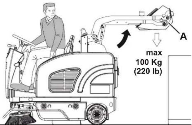
WARNING!
The hopper (11) must be emptied on level grounds only. Do not lift the hopper when the machine is on a slope.

WARNING!
When lifting and dumping the hopper (11), make sure that there are no people around the machine, especially near the hopper.

NOTE
When the hopper (11) is lifted, the vacuum system turns off automatically and the machine maximum speed is reduced for safety reasons.
To empty the hopper, move the machine close to the dustbin and proceed as follows.
- Lift the side and main brooms.
- Press the enabling switch (66) while pressing the hopper lifting switch (79) to lift the hopper (A, Fig. 2) up to the desired position.
- Drive the machine to the disposal area and engage the parking brake.
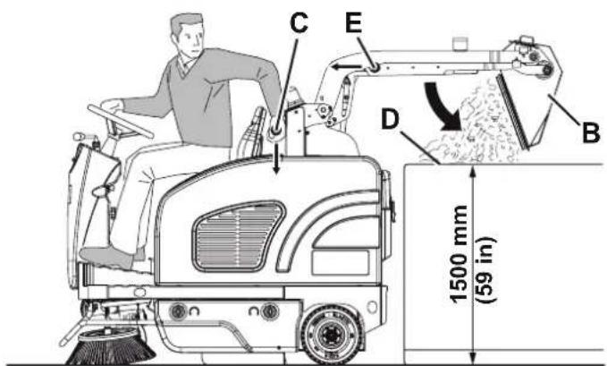
- Dump the hopper (B) with the lever (9) to discharge all dust and debris collected (C).

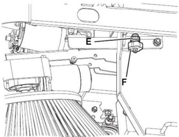
NOTE
If necessary, manually engage the hopper in position (A) with the returning handle (E) when the hoisting system is lifted and the hopper is disengaged (B).

CAUTION!
The hopper (A) can be dumped only when lifted at a minimum height of 35 cm approximately.
The maximum dumping height is approx. 150 cm.
- Lower the hopper by pressing both the enabling switch (66) and the switch (79).

NOTE
To ensure that the hopper (11) is fully retracted, check that the warning light (74) is off.
- The machine is ready to start sweeping and vacuuming again.
P100592
Figure 2
AFTER USING THE MACHINE
After working, before leaving the machine, perform the following procedures.
- Turn on the filter shaker shortly, by pressing the lower part of the switch (65).
– Empty the hopper (11) (see the procedure in the previous paragraph).
– Lift the main broom with the lever (63).
– Lift the side brooms with the lever (64).
- (For LPG version). Close the safety valve on the LPG tank (56), then let the engine run until all the fuel is expelled from the hoses (then the engine is stopped).
- Turn off the machine by turning the ignition key (61) to "0", then remove it.
- Engage the parking brake.
MACHINE LONG INACTIVITY
If the machine is not going to be used for more than 30 days, proceed as follows:
- Check that the machine storage area is dry and clean.
- (For Petrol version). Close the fuel tap (34).
– (For LPG version). Close the LPG tank safety valve. - Disconnect the negative connector (-) of the batteries (46).
- Handle the engine (42) as shown in the relevant Manual.
- (For machines equipped with dust guard system). Empty the tank (24) and clean the water filter (see the procedure in Maintenance chapter).
FIRST PERIOD OF USE
After the first 20 hours perform the following procedures:
- Change the engine oil (see the procedure in Maintenance chapter).
MAINTENANCE
The lifespan of the machine and its maximum operating safety are ensured by correct and regular maintenance.
The following table provides the scheduled maintenance. The intervals shown may vary according to particular working conditions, which are to be defined by the person in charge of the maintenance.
All scheduled or extraordinary maintenance procedures must be performed by qualified personnel, or by an authorised Service Center.
This Manual describes only the easiest and most common maintenance procedures.
For other maintenance procedures shown in the Scheduled Maintenance Table, refer to the Service Manual that can be consulted at any Service Center.

WARNING!
To perform maintenance procedures, the machine must be off, the ignition key removed, and, if necessary, the batteries must be disconnected.
Read carefully the instructions in the Safety chapter before performing any maintenance procedure.
SCHEDULED MAINTENANCE TABLE
| Procedure | Upon delivery | Every 10 hours | Every 50 hours | Every 100 hours | Every 200 hours | Every year |
| Engine oil level check (1) | ||||||
| Battery fluid level check (2) | ||||||
| Side and main broom height check | ||||||
| Engine air filter check (1) | ||||||
| Brake cable check and adjustment (3) | ||||||
| Hopper dust filter check and cleaning ("A" method) (4) | ||||||
| Hopper hydraulic lifting system oil level check (2) | ||||||
| Skirt height and operation check | ||||||
| Dust guard system water filter check and cleaning (optional) | ||||||
| Engine air filter cleaning (4) (4) | ||||||
| Hopper dust filter check and cleaning ("B" method) (4) | ||||||
| Filter shaker operation check (*) | ||||||
| Main broom driving belt visual inspection (*) | ||||||
| Engine oil change | (5) (6) | |||||
| Spark plug check/cleaning | ||||||
| Steering chain cleaning | (*) | |||||
| Safety system operation check | (2) | |||||
| Engine filter trap cleaning | ||||||
| Engine baffle plate cleaning | ||||||
| Fuel filter cleaning | (7) | |||||
| Brake pad check/adjustment/replacement | (*)(3) |
SCHEDULED MAINTENANCE TABLE (Continues)
| Procedure | Upon delivery | Every 10 hours | Every 50 hours | Every 100 hours | Every 200 hours | Every year |
| Hopper dust filter check and cleaning (“C” method) (4) | ||||||
| Main broom driving belt check and/or replacement (*) | ||||||
| Hopper gasket integrity check (*) | ||||||
| Lifted hopper sensor operation check/adjustment (*) | ||||||
| Motor carbon brush check and/or replacement (*) | ||||||
| Fuel valve filter cleaning (Petrol) (*) | ||||||
| Engine paper air filter replacement | ||||||
| Spark plug replacement | ||||||
| Engine idle speed check/adjustment (*) | ||||||
| Valve clearance check/adjustment (7) | ||||||
| Hydraulic system oil change (*) (8) | ||||||
| Supply hose replacement (LPG) (*) | ||||||
| Engine combustion chamber cleaning Every 500 hours (7) | ||||||
| Fuel hose check/replacement (Petrol) Every 2 years (7) | ||||||
(*) For the relevant procedure, refer to the Service Manual.
(1) Daily or after using the machine.
(2) Or before start-up.
(3) Or more frequently if the machine is used on slopes.
(4) Or more often in dusty areas.
(5) Or every 6 months.
(6) And after the first 20 running-in hours.
(7) Maintenance procedures to be performed by an authorised Honda dealer.
(8) Change the hydraulic system oil after 500 hours or every year.
BRAKE CABLE CHECK AND ADJUSTMENT

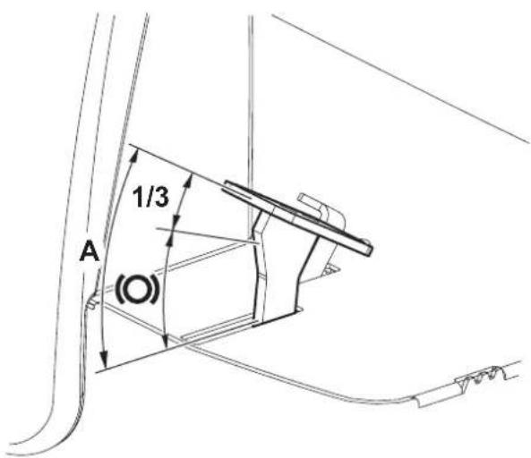
WARNING!
Frequent and extended use of the service brake (6), especially on slopes, can cause a rapid wear of the pads. Keep the braking system in maximum efficiency.
If the stroke of the brake pedal exceeds 1/3 of the total stroke (A, Fig. 3) before starting to operate on the braking masses, adjust the brake cable as shown:
- Drive the machine on a level ground.
- Turn the ignition key (61) to "0".
- Ensure that the machine cannot move by placing opposite wedges on the rear wheels.
-
Steer the front wheel to the right, about 90^ , so that the brake system becomes accessible.
-
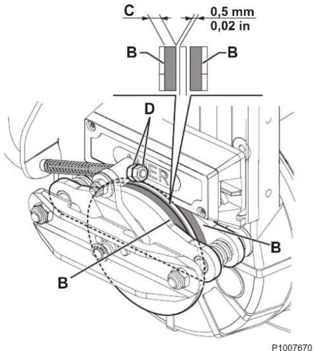
Check braking masses (B, Fig. 4) for wear. The thickness (C) of the pads must be 1 mm or more. If necessary, contact a Service Center for braking masses adjustment/replacement.
-
Loosen the locknut and the nut (D) to adjust the brake cable.
-
Turn the nut until the gap between brake disc and braking masses is 0.5 mm.
-
Tighten the locknut on the nut (D).
-
Remove the wedges from the rear wheels.
Check the proper adjustment of the brake cable by pushing the machine manually (do not apply the brake).
Perform brake tests and check the proper operation of the service and parking brake.
If the brake cable adjustment is no longer possible and the braking system cannot be properly adjusted, contact a Service Center.

CAUTION!
The service manual shows all braking system check/adjustment and replacement procedures.
P100769
Figure 3
MAIN BROOM HEIGHT CHECK AND ADJUSTMENT

NOTE
Brooms with harder or softer bristles are available. This procedure is applicable to all types of brooms.
-
Check the main broom height as shown below:
-
Drive the machine on a level ground.
- Engage the parking brake.
- Lower the main broom and turn it pressing the accelerator pedal for approx. one minute. Do not operate the broom continuously in order not to overheat the drive motor braked.
- Stop and lift the main broom, then move the machine and switch it off.
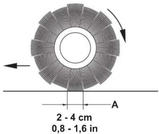
- Check that the main broom print (A, Fig. 5), along its length, is 2 to 4 cm wide.
If the print (A) is not within specifications, adjust the main broom height according to the following procedure.
-
Turn the knob (B, Fig. 6) as shown below:
-
to increase the print width, turn the knob counterclockwise
• to decrease the print width, lift the broom with the lever (63) and then turn the knob clockwise

NOTE
The knob can be used both to adjust the print and to adjust the broom according to the bristle wear.
- Perform step 1 again to check that the main broom is at the correct distance from the ground.
- When the broom is too worn to be adjusted, replace it as shown in the next paragraph.

NOTE
After the main broom height has been adjusted, check that the broom overload warning light (75) does not flash in the first minutes of operation. Otherwise the pressure on the floor must be reduced by means of the adjusting knob (62).

NOTE
If it is not possible to adjust the print (A, Fig. 5) properly, because the pressure on the floor at the ends of the broom is different, refer to the Service Manual.
P100593
Figure 5
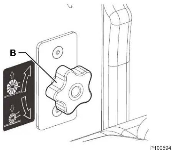
Figure 6
MAIN BROOM REPLACEMENT

WARNING!
It is advisable to wear protective gloves when replacing the main broom because there can be sharp debris between the bristles.
- Drive the machine on a level ground and engage the parking brake.
- Turn the ignition key (61) to "0" and remove it.
- Remove the left door (13) by turning the fasteners.
- Unscrew and remove the knob (A, Fig. 7).
- Turn the levers (B).
- Remove the broom compartment latch (C) by grabbing it from its fold (D).
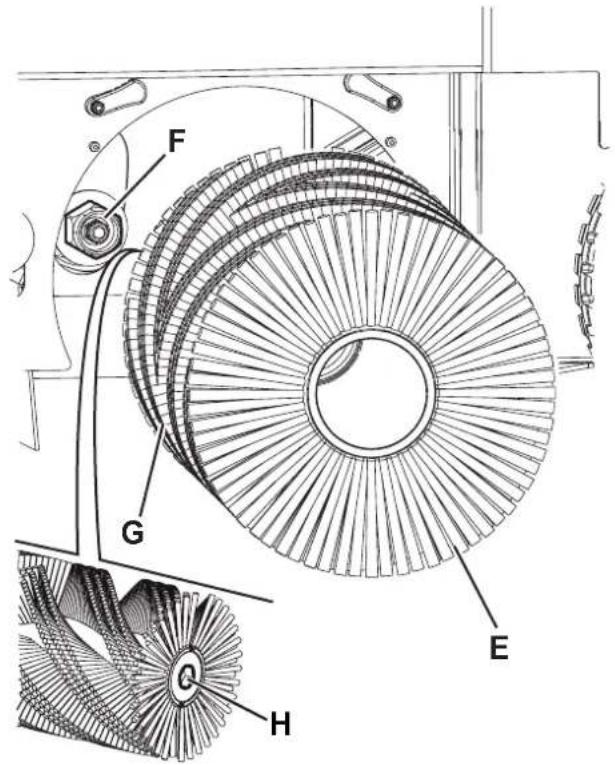
- Remove the main broom (E, Fig. 8).
- Check that the drive hub (F) is free from dirt or foreign materials (cords, rags, etc.) accidentally rolled up.
- The new main broom must be installed with the bristles rows bent as shown in the figure (G).
- Install the new broom and ensure that the hexagonal mesh (H) fits into the relevant drive hub (F).
- Install the broom compartment latch (C, Fig. 7) by turning the levers (B) and screwing down the knob (A).
- Close the left door (13) by turning the fasteners.
- Check and adjust the main broom height as shown in the previous paragraph.
P100595
Figure 7
P100596
Figure 8
SIDE BROOM HEIGHT CHECK AND ADJUSTMENT

NOTE
Brooms with harder or softer bristles are available. This procedure is applicable to all types of brooms.
-
Check the side broom distance from the ground, according to the following procedure:
-
Drive the machine on a level ground.
- Keep the machine stationary, lower the side brooms and turn them on for a few seconds.
- Stop and lift the side brooms, then move the machine.
- Check that the side broom prints are as shown in the figure (A and B, Fig. 9).
If the print is not within specifications, adjust the side broom height according to the following procedure.
- Engage the parking brake.
- Turn the ignition key (61) to "0".
- Remove the right or left door (12 or 13) by turning the fasteners.

NOTE
The right door fasteners must be turned with a tool.
- For the right side broom, operate on the idle gear by loosening the ring nut (C, Fig. 10) and by adjusting the adjuster (D) until the correct print (A, Fig. 9) is achieved. Then fasten the adjuster with the ring nut (C, Fig. 10). For the left side broom, operate on the idle gear by loosening the ring nut (E) and by adjusting the adjuster (F) until the correct print (B, Fig. 9) is achieved. Then fasten the adjuster with the ring nut (E, Fig. 10).
- Perform step 1 again to check the proper adjustment of the side broom height.
- When the broom is too worn to be adjusted, replace it as shown in the next paragraph.

NOTE
If necessary, the side broom tilting can be adjusted too (see the procedure in the Service Manual).
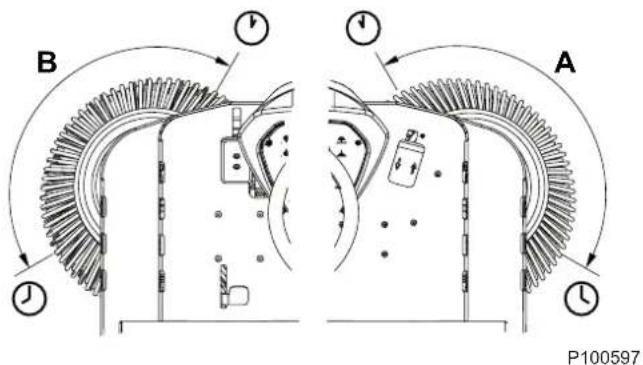
Figure 9
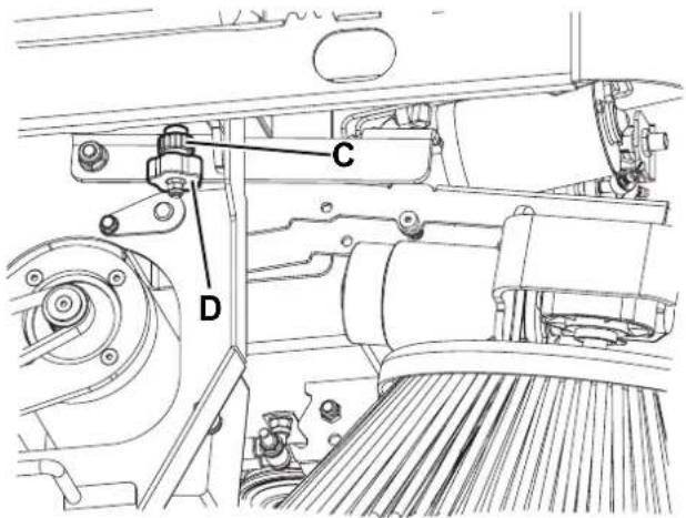
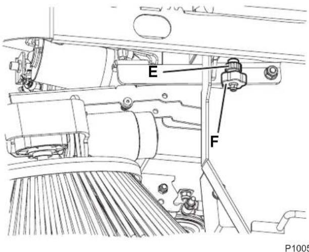
Figure 10
SIDE BROOM REPLACEMENT

WARNING!
It is advisable to wear protective gloves when replacing the side broom because there can be sharp debris between the bristles.
- Drive the machine on a level ground and engage the parking brake.
- Turn the ignition key (61) to "0".
- Lift the side broom with the lever (64).
- Remove the pin clip (A, Fig. 11), then remove the pin.
- Remove the broom (B) and recover the protection flange (C).
- Install on the hub (D) the new side broom with the protection flange.
- Insert the fastening pin and engage its safety clip.
- Check and adjust the side broom height as shown in the previous paragraph.
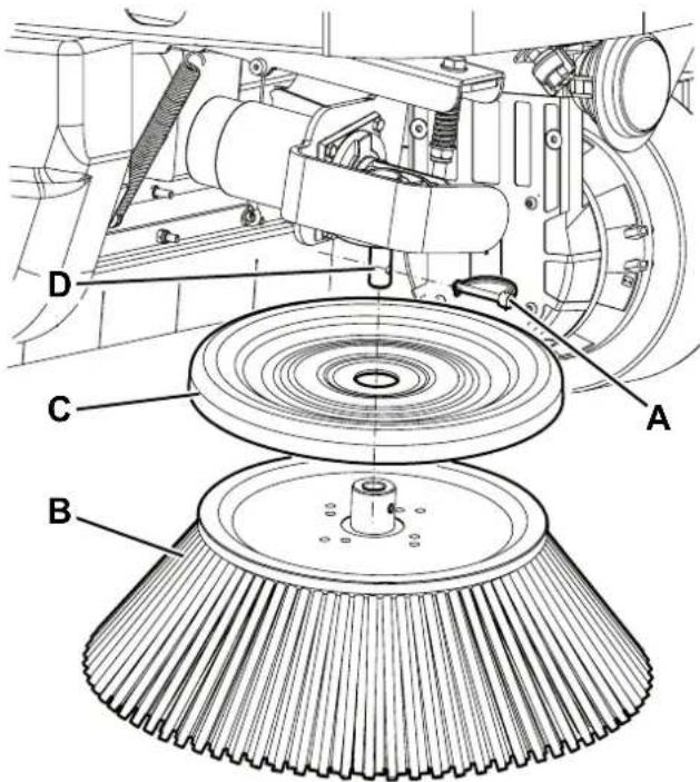
Figure 11
P100599
PANEL DUST FILTER CLEANING AND INTEGRITY CHECK
The dust filter must be regularly cleaned to maintain the efficiency of the vacuum system. Follow the recommended filter service intervals for the longest filter life.

WARNING!
- Wear safety glasses when cleaning the filter.
- Do not puncture the filter.
– Clean the filter in a well-ventilated area. -
Wear appropriate dust mask to avoid breathing in dust.
-
Drive the machine on a level ground, engage the parking brake and turn the ignition key (61) to "0".
- Open the engine compartment hood (18) with the handle (41) and fasten it with the support rod (53).
- Disconnect the vacuum system motor connector (54).
- Release the fasteners (A, Fig. 12) and remove the vacuum system cover (B).
- (For LPG version). Disconnect the connector (C, Fig. 13) from the filter shaker.
- Unscrew the knobs (D) and remove the filter shaker assembly (E).
- (For Petrol version). Fasten the filter shaker assembly to the holder (F).
- Lift the dust filter (G) and remove it from the machine.
- Clean the filter using one of the methods below:
Method "A"
Collect dust from the filter. Gently tap the filter against a flat surface (with the dirty side down) to remove dust and dirt.

NOTE
Take care not to damage the metal lip which extends past the gasket.
Method "B"
Collect dust from the filter. Blow compressed air (maximum pressure 6 Bar) into the clean side of the filter (in the opposite direction of the airflow).
Method "C"

CAUTION!
For the paper filter (standard for FLOORTEC
R 870): do not use water or detergents to clean it; the filter could be damaged.
Collect dust from the filter. Then soak the filter in warm water for 15 minutes, then rinse it under a gentle stream of water (maximum pressure 2.5 Bar). Let the filter dry completely before installing it back into the machine.
For a better cleaning, it is allowed to wash the filter with water and non-lathering detergents.
This provides better quality cleaning but reduces the life of the filter, which will have to be replaced more frequently. The use of inadequate detergents can damage the filter.
-
Install the filter in the reverse order of removal and note the following:
-
Clean the filter housing.
• Install the filter with the strainer facing upwards (arrow (H, Fig. 13) upwards). - If the filter gasket is damaged or missing, it must be replaced.
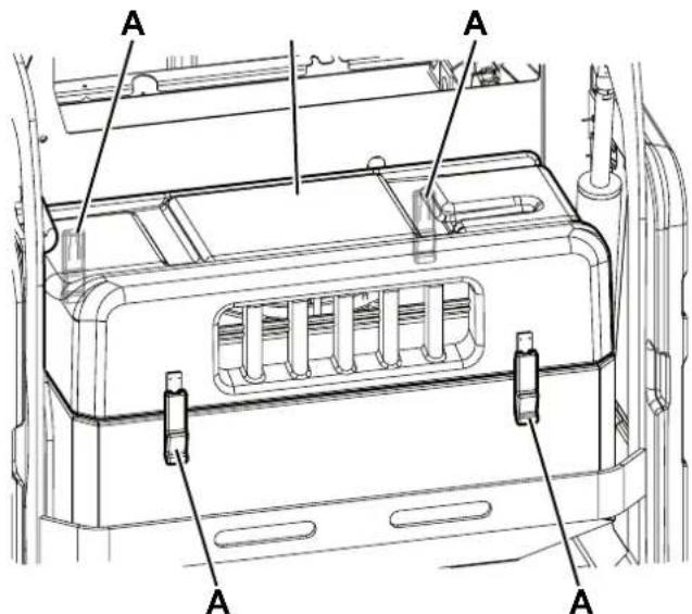
Figure 12
P100600
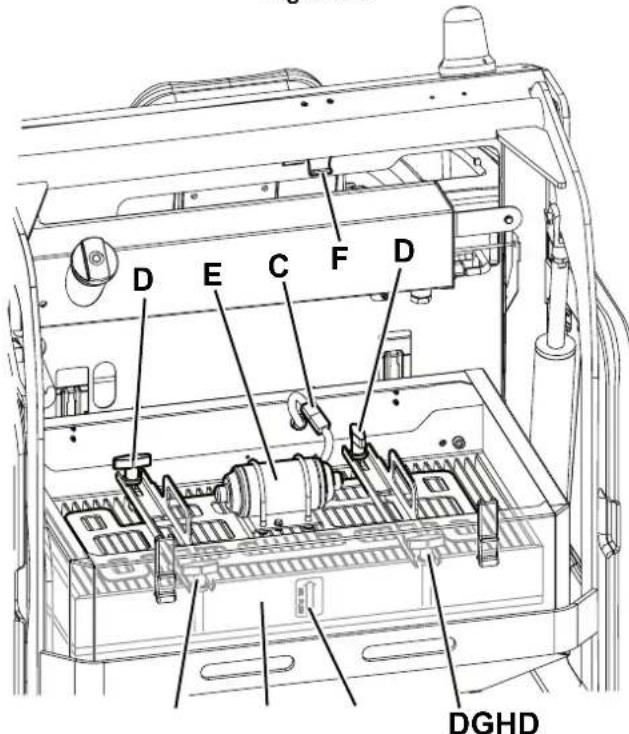
Figure 13
P100601
Preliminary Operations
-
Empty the hopper (as shown in Use chapter), because the weight of the waste inside the hopper can affect the skirt height check.
-
Drive the machine on a level ground that is suitable for checking the skirt height.
-
Turn the ignition key (61) to "0" and engage the parking brake.
Side Skirt Check
-
Remove the left and right doors (13 and 12) by turning the fasteners.
-
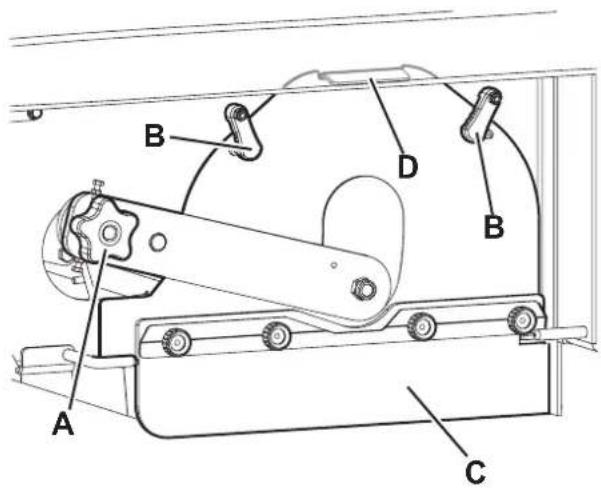
Check the side skirts (A, Fig. 14) for integrity. Replace the skirts when they have cuts (C, Fig. 15) larger than 20 mm or cracks/tears (D) larger than 10 mm (for skirt replacement, refer to the Service Manual).
-
Check that the distance from the floor of the side skirts (A, Fig. 14) is within 0 - 3 mm (Fig. 16). If necessary, loosen the knobs (B, Fig. 13) and adjust the skirt position. Then tighten the knobs (B).
Front and Rear Skirt Check
-
Remove the main broom as shown in the relevant paragraph.
-
Check the front skirt (E, Fig. 17) and rear skirts (F) and (G) for integrity. Replace the skirts when they have cuts (C, Fig. 15) larger than 20 mm or cracks/tears (D) larger than 10 mm.
-
Check that the front (E, Fig. 17) and rear skirt (G) slightly rub ground without being detached from it (Fig. 18).
-
For the skirt replacement, see the Service Manual.
Reassembly
- Assemble the components in the reverse order of disassembly.
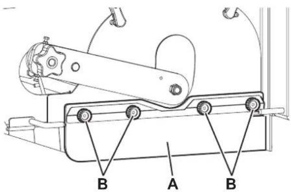
Figure 14
P100602
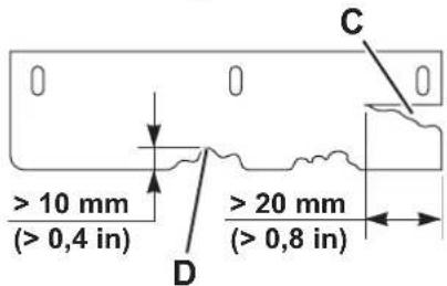
Figure 15
P100603
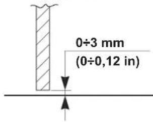
Figure 16
P100604
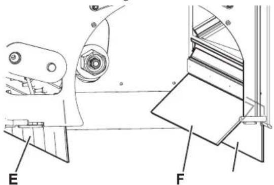
Figure 17
P100605
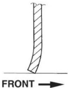
Figure 18
P100606
DUSTGUARD™ SYSTEM WATER FILTER CLEANING (OPTIONAL)

NOTE
To prevent water from flowing out when cleaning the filter, turn on the dust guard system and empty the system tank (24).
- Drive the machine on a level ground.
- Turn the ignition key (61) to "0" and engage the parking brake.
- From under the machine (A, Fig. 19), reach the water filter assembly (B) of the dust guard system.
- Unscrew and remove the transparent cover (C) with the gasket (D), then remove the filter strainer (E).
- Clean and install them on the holder (F).

NOTE
Install the gasket (D) and the filter strainer (E) in the housings of the cover and of the filter assembly holder.
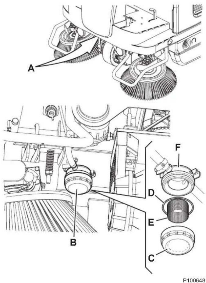
Figure 19
HOPPER HYDRAULIC LIFTING SYSTEM OIL LEVEL CHECK

WARNING!
Procedure to be performed with the hopper (11) fully retracted.
- Turn the ignition key (61) to "0" and engage the parking brake.
- Open the engine compartment hood (18) with the handle (41) and fasten it with the support rod (53).
- Check that the oil level in the tank (52) is between the minimum (MIN) and maximum (MAX) marks shown in figure 20.
- If necessary, add oil through the plug (A, Fig. 20), using the oil specified in Technical Data paragraph.
- Remove the support rod (53) and close the hood (18).
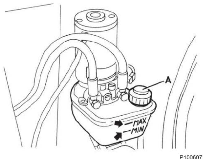
Figure 20
ENGINE AIR FILTER CHECK/CLEANING

CAUTION!
Running the engine without air filters, or with damaged filters, can cause a faster engine wearing.
- Drive the machine on a level ground and engage the parking brake.
- Turn the ignition key (61) to "0".
- Open the engine compartment hood (18) with the handle (41) and fasten it with the support rod (53).
- Lift and disassemble the right side bulkhead (45).
- Remove the wing nut (A, Fig. 21) and remove the cover (B).
- Remove the wing nut (C) and disassemble the filter element.
- Separate the foam filter (D) from the paper filter (E).
- Check both filters and replace them if necessary. Replace the paper filter (E) when required (see the scheduled maintenance table).
- To use again the filters, clean them as shown below:
- Paper filter (E): Hit the filter several times against a hard surface to remove the dust, or blow compressed air (no more than 207 kPa (2.1 kgf/cm)) from inside the filter. Do not use a brush, otherwise the fibre will be damaged.
- Foam filter (D): Clean with warm water and soap, rinse and let it dry completely, or clean with a non-flammable solvent and let it dry. Soak the filter in clean engine oil, then squeeze it to remove the surplus oil.
- Clean with a wet cloth the base (F) and the cover (B) of the air filter. Pay attention to avoid that dirt enters the air duct (G) to the carburettor.
- Assemble the foam filter (D) on the paper filter (E), then assemble the filter element. Ensure that the gasket (H) is properly placed under the filter element. Screw down the filter element wing nut (C).
- Install the cover (B) and screw down the wing nut (A).
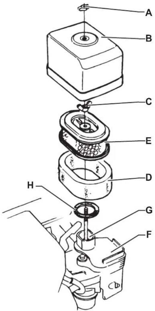
Figure 21
P100615
ENGINE OIL LEVEL CHECK

CAUTION!
Running the engine with a low oil level can damage the engine itself.

NOTE
The oil alert system will automatically stop the engine before the oil level goes down under the safety limit. To avoid a sudden engine stop, always check the oil level before each start-up.
- Drive the machine on a level ground and engage the parking brake.
- Turn the ignition key (61) to "0".
- Open the engine compartment hood (18) with the handle (41) and fasten it with the support rod (53).
- Lift and disassemble the right side bulkhead (45).
- Remove the oil filler plug/dipstick (A, Fig. 22) and clean it.
- Insert the oil filler plug/dipstick in the filler neck (B), but do not tighten it, then remove it to check the oil level.
- If the oil level is near or under the lower limit mark (C) on the dipstick, top up with the specified oil up to the upper limit mark (D) (lower edge of the oil filling hose). Do not overfill.
- Install the oil filler plug/dipstick (A).
ENGINE OIL CHANGE

CAUTION!
The discharged engine oil must be disposed of properly according to the Law in force.

NOTE
It is advisable to change the oil when the engine is still hot, to make the oil downflow easier.
- Drive the machine on a level ground and engage the parking brake.
- Turn the ignition key (61) to "0".
- Open the engine compartment hood (18) with the handle (41) and fasten it with the support rod (53).
- Lift and disassemble the right side bulkhead (45).
- Remove the oil filler plug/dipstick (A, Fig. 22), place the hose (E) in a position that eases the oil drain, then remove the plug (F).
- Remove the oil drain plug (F) from the hose and drain the oil into a suitable container, then install the oil drain plug and hose.
- Pour new oil in the filler neck (B) up to the upper limit mark (D) (lower edge of the oil filling hose) on the dipstick.

NOTE
As for engine oil type and quantity, see the Technical Data chapter and the Engine Manual.
- Install the oil filler plug/dipstick (A) and tighten it.

Figure 22
P100616
ENGINE FILTER TRAP CLEANING (for Petrol version)

WARNING!
The petrol is highly flammable and explosive, it can burn or cause serious injuries.
Turn off the engine, and keep it far from sparks, flames and other sources of heat.
Handle the fuel outdoors only.
Wipe immediately any fuel accidentally spilled out.
- Drive the machine on a level ground and engage the parking brake.
- Turn the ignition key (61) to "0".
- Open the engine compartment hood (18) with the handle (41) and fasten it with the support rod (53).
- Lift and disassemble the right side bulkhead (45).
- Move the fuel lever (A, Fig. 23) to OFF, then remove the fuel filter cup (B) and the O-ring (C).
- Wash the fuel filter cup (B) and the O-ring (C) with a non-flammable solvent, then dry them accurately.
- Place the O-ring (C) and assemble the filter cup (B) by tightening it securely.
- Move the fuel lever (A) to ON and check for leakages. If any leakage is found, replace the O-ring (C).

Figure 23
P100617
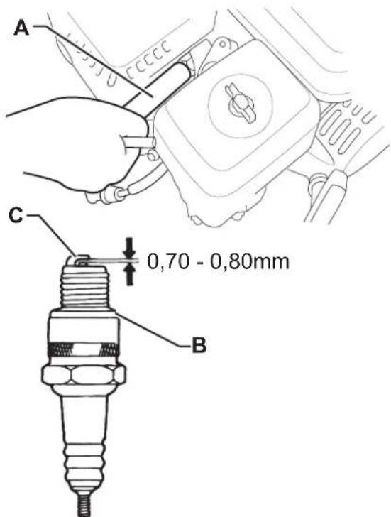
ENGINE SPARK PLUG CHECK/REPLACEMENT
For the type of spark plug to be used, see Technical Data chapter.

NOTE
A wrong spark plug can damage the engine.
- Drive the machine on a level ground and engage the parking brake.
- Turn the ignition key (61) to "0".
- Open the engine compartment hood (18) with the handle (41) and fasten it with the support rod (53).
- Lift and disassemble the right side bulkhead (45).
- Disconnect the spark plug cap and remove dirt around the spark plug.
- Remove the spark plug with a proper wrench (A, Fig. 24).
- Check the spark plug. Replace it if it is damaged, dirty, if the sealing washer (B) is damaged or if the electrode is worn.
- Measure the distance between the spark plug electrodes with a feeler gauge. Correct the distance by bending carefully the side electrode (C). The distance between the electrodes must be of 0.70 - 0.80 mm.
- Install the spark plug manually with great care, to avoid tightening it improperly.
- Once the spark plug is in place, tighten it with a proper wrench to press the sealing washer.
- When a new spark plug is installed, tighten 1/2 turn once the spark plug is in place to press the washer.
- When the original spark plug is reinstalled, tighten 1/8 - 1/4 turn once the spark plug is in place to press the washer.

NOTE
A loose spark plug can overheat and damage the engine.
Do not over-tighten, otherwise the threads in the cylinder head can be damaged.
- Install the cap on the spark plug.
P100618
Figure 24
ENGINE BAFFLE PLATE CLEANING

WARNING!
If the engine was running, the silencer will be very hot. Let it cool down before operating on the baffle plate.
- Drive the machine on a level ground and engage the parking brake.
- Turn the ignition key (61) to "0".
- Open the engine compartment hood (18) with the handle (41) and fasten it with the support rod (53).
- Lift and disassemble the right side bulkhead (45).
- Remove the screws (A, Fig. 25) and carefully remove silencer guard (B).
- Remove the screws (C) and remove the exhaust manifold (D).
- Remove the screws (E) and carefully remove silencer guard (F).
- Remove the screw (G) and remove the baffle plate (H) from the silencer.
- Use a brush to remove the carbon deposits from the baffle plate shield (I). Take care not to cause damage to the shield. Replace the baffle plate if it cracked or perforated.
- Install the baffle plate (H), the silencer guard (F) and the exhaust manifold (D).
- Assemble the components in the reverse order of disassembly.
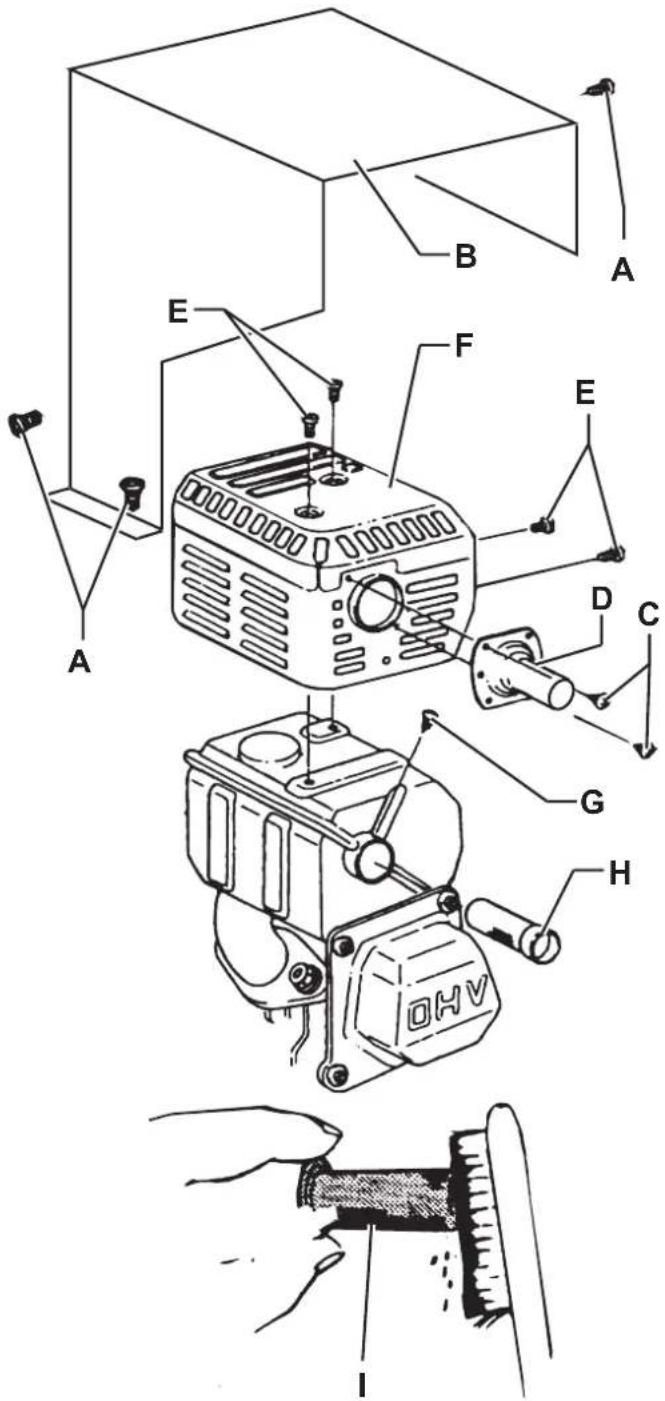
Figure 25
P100619
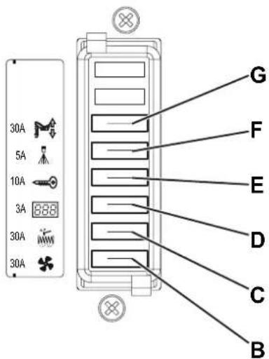
FUSE CHECK/REPLACEMENT/RESET
- Drive the machine on a level ground and engage the parking brake.
- Turn the ignition key (61) to "0".
- Open the engine compartment hood (18) with the handle (41) and fasten it with the support rod (53).
- Disconnect the negative connector (-) of the batteries (46).
Lamellar Fuse Check/Replacement
- Remove the fuse box cover (A, Fig. 26).
-
Check/replace the relevant fuse among the following (Fig. 27):
• (B): F1 vacuum system motor fuse (30 A).
• (C): F2 filter shaker motor fuse (30 A).
• (D): F3 display electronic board fuse (3 A).
• (E): F4 main fuse (key circuit) (10 A).
• (F): F5 dust guard system fuse (5 A) (optional).
• (G): F6 hopper lifting fuse (30 A). -
Remove the screws (H, Fig. 26), then remove the cover (I) of the electrical component box (50).
-
Check/replace the following fuses:
• (J): FA main broom motor fuse (50 A).
• (K): F0 main fuse (150 A).
• (L): FC battery charge fuse (80 A).
Fuse Check
- Check one of the following fuses (Fig. 26) for deactivation:
• (M): FR1 right side broom motor fuse (15 A).
• (N): FR2 left side broom motor fuse (15 A) (optional). Reset any deactivated fuse, when the component that caused deactivation has fully cooled down.
Reassembly
- Connect the negative connector (-) of the batteries (46).
- Remove the support rod (53) and close the hood (18).
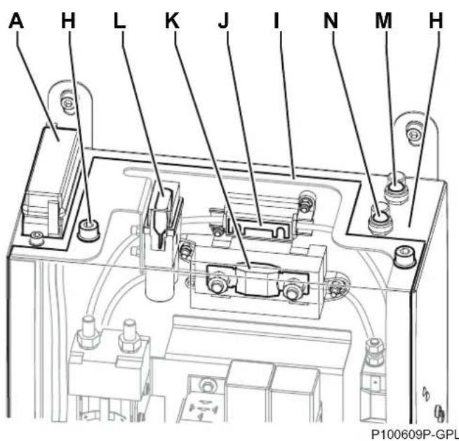
Figure 26
P100610P-GPL
Figure 27
SAFETY FUNCTIONS
The machine is equipped with the following safety functions.
EMERGENCY PUSH-BUTTON
It is to the left side of the operator (77). It has to be pressed in case of emergency, to stop all the machine functions.
DRIVER'S SEAT MICROSWITCH
It is located inside the driver's seat (3) and it does not allow the machine drive system to operate if the operator is not seated on the driver's seat.
HOPPER POSITION SENSOR
When the hopper is lifted, the sensor reduces the machine speed, turns off the vacuum fan and stops the broom rotation.
HOPPER SAFETY VALVE
When the hopper is lifted, the safety valve on the hydraulic lifting cylinder prevents the hopper to accidentally lower.
TROUBLESHOOTING
Trouble Possible cause Remedy
| The engine oil level is too low. Check the engine oil level and top up. (*) | |||
| The fuel does not reach the carburettor. | Check that the fuel tap is open (Petrol). | ||
| Check that the tank safety valve is open (LPG). | |||
| The engine does not start with the ignition key. | The air control is in standard position. Turn the lever to cold start position. | ||
| The spark plug does not produce a spark. Check or replace the spark plug. (*) | |||
| The F3 and/or F0 fuse is open. Check/replace the fuses. | |||
| The batteries are discharged. Recharge with a proper battery charger. | |||
| The emergency push-button has been pressed. | Check and release the emergency push-button. | ||
| The engine stops during operation. | The engine oil level is too low. Check the engine oil level and top up. (*) | ||
| The fuel filter is dirty (Petrol). Clean the fuel filter. (**) | |||
| The drive pedal has been pressed before or at machine start-up. | Start up the machine without pressing the drive pedal. | ||
| The machine does not move when pressing the drive pedal and the warning light (76) flashes. | Drive system failure. | Turn off the machine and then turn it on again. | |
| If the trouble persists, contact the Service Center. | |||
| When pressing the drive pedal, the machine does not move, or it moves slowly. | The parking brake is engaged. Check and release the parking brake. | ||
| The hopper is not completely lowered. Lower the hopper to the end-of-stroke. | |||
| Decrease the main broom pressure on the floor. | |||
| The display (69) shows the code. | The working conditions are disadvantageous for the batteries. | Avoid driving uphill for long. | |
| Turn off the working lights. | |||
| If the problem persist, maybe it is necessary to calibrate the engine rpm. (**) | |||
| The display (69) shows the code. | The battery charge is excessive. | Turn off the engine each time the machine is stopped. | |
| If the problem persist, maybe it is necessary to calibrate the engine rpm. (**) | |||
| Turn off the machine and then turn it on again. | |||
| The main broom does not work and the warning light (75) flashes. | The safety system has activated. | Check the condition of the main broom (debris that slows down the broom or excessive pressure on the ground). | |
| The FA fuse is open. | Wait for the main broom motor to cool down, then replace the fuse. | ||
TROUBLESHOOTING (Continues)
| Trouble Possible cause Remedy | ||
| The side brooms do not operate. | The FR1 or FR2 circuit breaker of the side brooms is open. | Wait for the side broom motor to cool down, then reset the fuse by pressing the relevant push-button. |
| The machine collects little debris/dust. | The dust filter is clogged. | Clean the dust filter by using the filter shaker or by disassembling it. |
| The hopper is full. Empty the hopper. | ||
| The skirts are not properly adjusted or are broken. | Adjust/replace the skirts. | |
| The brooms are not properly adjusted. Adjust the | broom height. | |
| The F1 fuse is open. Replace the fuse. | ||
| The hopper does not lift. | The hydraulic system oil level is incorrect. | Check the hydraulic system oil level in the tank. |
| The F6 fuse is open. Replace the fuse. | ||
| The hopper does not dump. The hopper is too low. | Lift the hopper at a minimum height of 350 mm. | |
| The hopper does not lower. | In case of low temperatures, the hydraulic system oil is slow in flowing through the safety valve. | Wait a few moments to let the hydraulic system oil flow. |
| The filter shaker does not work. | The F2 fuse is open. Replace the fuse. | |
| The filter shaker is disconnected. Connect the filter shaker connector. | ||
| The dust guard system (optional) does not work. | The water tank is empty. Fill the tank. | |
| The nozzles or the water filter are clogged. Clean. | ||
| The pump is faulty. Replace. (**) | ||
| The F5 fuse is open. Replace the fuse. | ||
(*) For the relevant instructions, see also to the Engine Manual.
(**) Procedure to be performed by Nilfisk Service Center.
For further information contact a Nilfisk Service Center, where it is possible to consult the Service Manual.
SCRAPPING
Have the machine scrapped by a qualified scraper.
Before scrapping the machine, remove and separate the following materials, which must be disposed of properly according to the Law in force:
- Batteries
– Polyester dust filter - Main and side brooms
- Hydraulic system oil
– Hydraulic system oil filter
– Plastic hoses and components
– Electrical and electronic components (*)
(*) Refer to the nearest Nilfisk Center especially when scrapping electrical and electronic components.
INHOUDSOPGAVE
INLEIDING 2
DOEL EN INHOUD VAN DEZE HANDLEIDING....2
BETREFFENDE PERSONEN 2
OPBERGEN VAN DE HANDLEIDING....2
CONFORMITEITSVERKLARING 2
IDENTIFICATIEGEGEVENS 2
ANDERE GEBRUIKERSHANDLEIDINGEN....2
VERVANGINGSONDERDELEN EN ONDERHOUD 2
MODIFICATIES EN VERBETERINGEN....3
BEDRIJFSCAPACITEIT 3
ALGEMENE OPMERKINGEN....3
VERPAKKING VERWIJDEREN/AFLEVERING 3
VEILIGHEID 3
SYMBOLEN OP DE MACHINE 3
SYMBOLEN IN DE HANDLEIDING....4
ALGEMENE INSTRUCTIES 4
BESCHRIJVING VAN DE MACHINE 7
BOUW VAN DE MACHINE 7
BEDIENINGSPANEELE EN KNOPPEN 10
ACCESSOIRES/OPTIES....11
P100611
P100611
BEDIENINGSPANEELE EN KNOPPEN
61. Contactsleutel:
P100769
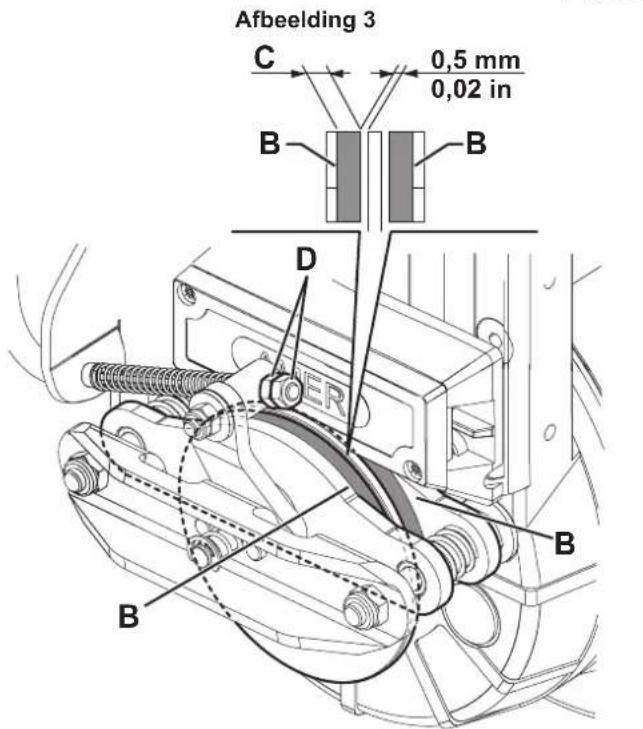
P100600
Afbeelding 12
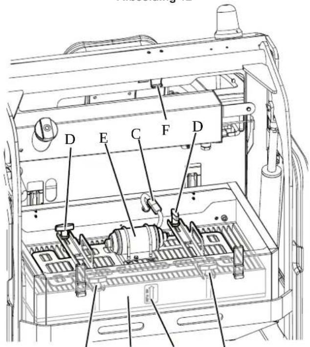
Afbeelding 19
P100648
CONTROLE VAN HET OLIEPEIL VAN HET HYDRAULISCH SYSTEEM VOOR HET OPHEFFEN VAN DE AFVALCONTAINER

LET OP!
Afbeelding 20
P100607
CONTROLE/REINIGING VAN DE LICHTFILTERS VAN DE MOTOR

WAARSCHUWING!
Afbeelding 21
P100615
CONTROLE VAN HET MOTOROLIEPEIL

WAARSCHUWING!
Afbeelding 25
P100619
CONTROLE / VERVANGING / RESETTEN VAN DE ZEKERINGEN
Afbeelding 26

P100610P-GPL
Afbeelding 27