
SW900 - Sweeper NILFISK - Free user manual and instructions
Find the device manual for free SW900 NILFISK in PDF.
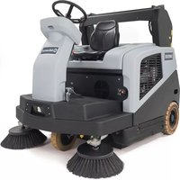
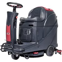
| Product type | Industrial walk-behind sweeper |
| Brand | Nilfisk |
| Model | SW900 |
| Sweeping width (1 side brush) | 825 mm |
| Sweeping width (2 side brushes) | 1050 mm |
| Dimensions (L x W x H) in working position | 1390 x 870 x 1100 mm |
| Dimensions (L x W x H) with handle folded | 1050 x 870 x 840 mm |
| Empty weight (without batteries) | 82 kg |
| Total weight in working order | 143 kg |
| Maximum weight in working order (GVW) | 176 kg |
| Power supply | Lead-acid batteries 12 V (100-200 Ah C5) |
| Main motor power | 680 W |
| Working speed | 4.5 km/h |
| Working autonomy | 3 h |
| Waste container capacity | 60 L |
| Maximum transportable weight | 30 kg |
| Filter type | Polyester (standard) or paper (optional) with electric shaker |
| Vibration level (ISO 5349-1) | < 2.5 m/s² |
| Sound pressure level (ISO 11201) | 70 ± 3 dB(A) |
| Maximum operating slope | 2 % |
| Main functions | Sweeping, suction, electric shaker, wet by-pass system |
| Regular maintenance | Container emptying, filter cleaning, brush height check, battery charging |
| Safety | Container microswitch, ignition key, resettable fuses, thermal protection |
| Spare parts | Brushes, filters, belts, fuses, batteries (available from Nilfisk) |
| Repairability | Maintenance by qualified personnel or approved Nilfisk service center |
Frequently Asked Questions - SW900 NILFISK
User questions about SW900 NILFISK
0 question about this device. Answer the ones you know or ask your own.
Ask a new question about this device
Download the instructions for your Sweeper in PDF format for free! Find your manual SW900 - NILFISK and take your electronic device back in hand. On this page are published all the documents necessary for the use of your device. SW900 by NILFISK.
USER MANUAL SW900 NILFISK
08/2013 Revised 10/2013
(2)
1465366000

Deutsch
Français
English
Nederlands
natural_image
Line drawing of a cleaning or cleaning service robot with visible blades and wheels (no text or symbols)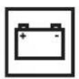
Model:
9084110010
Сертификат за съответствие Osvědčení o shodě Konformitätserklärung Overensstemmelsescertifikat Declaración de conformidad Vastavussertifikaat Déclaration de conformité Yhdenmukaisuustodistus Conformity certificate
Πιστοποιητικό συμμόρφωσης Megfelelősségi nyilatkozat Potvrda sukladnosti Dichiarazione di conformità Atitikties deklaracija Atbilstības deklarācija Konformitetssertifisering Conformiteitsverklaring Declaração de conformidade
Deklaracja zgodności Certificat de conformitate Заявление о соответствии Överensstämmelsecertifikat Certifikát súladu Certifikat o ustreznosti Uyumluluk sertifikası
CE
Модел / Model / Modell / Model / Modelo / Mudel / Modèle / Malli / Model / Movtélo / Modell / Model / Modello / Modelis / Modelis / Modell / Model / Modelo / Model / Model / Модель / Modell / Model / Model / Model :
SW900
Tínp / Typ / Typ / Type / Tipo / Tüüp / Type / Tyuppi / Type / Túpoç / Típus / Vrsta / Tipo / Tipas / Tips / Type / Type / Tipo / Typ / Tip / Tínp / Typ / Typ / Tip / Tip :
SWEEPER
Сериен номер / Výrobní číslo / Seriennummer / Serienummer / Número de serie / Seerianumber / Numéro de série / Sarjanumero / Serial number / Σειριακός αριθμός / Sorozatszám / Serijski broj / Numero di serie / Serijos numeris / Sērijas numurs / Serienummer / Serienummer / Número de série / Numer seryjny / Numār de serie / Серийный номер / Serienummer / Výrobné číslo / Serijska številka / Seri Numarası :
Година на производство / Rok výroby / Baujahr / Fabrikationsår / Año de fabricación / Väljalaskeaasta / Année de fabrication / Valmistusvuosi / Year of construction / Έτος κατασκευής / Gyártási év / Godina izgradnje / Anno di costruzione / Pagaminimo metai / Izgatavošanas gads / Byggeår / Bauwjaar / Ano de fabrico / Rok produkcji / Anul fabricației / Год выпуска / Tillverkningsår / Rok výroby / Leto izdelave / Leto izdelave/Imal yili :

The undersigned certify that the above mentioned model is produced in accordance with the following directives and standards. The technical file is compiled by the manufacturer.

Authorized signatory: Sergio Coccapani, R&D Director
Date: Signature:

INHALTSVERZEICHNIS
EINLEITUNG......2
P100813
P100814
Abbildung 3
P100818
HAUPTKEHRWALZE AUSWECHSELN

HINWEIS!
Abbildung 4
P100819
CONSERVATION DU MANUEL....2
DÉCLARATION DE CONFORMITÉ 2
DONNÉES D'IDENTIFICATION 2
AUTRES MANUELS DE RÉFÉRENCE....2
PIÈCES DE RECHANGE ET ENTRETIEN 2
MODIFICATIONS ET AMÉLIORATIONS....2
CAPACITÉS OPÉRATIONNELLES 3
CONVENTIONS 3
DÉBALLAGE / LIVRAISON....3
SÉCURITÉ .... 3
SYMBOLES VISIBLES SUR LA MACHINE....3
SYMBOLES UTILISÉS DANS LE MANUEL....4
INSTRUCTIONS GÉNÉRALES 4
DESCRIPTION DE LA MACHINE 6
STRUCTURE DE LA MACHINE....6
ACCESSOIRES / OPTIONS....8
CARACTÉRISTIQUES TECHNIQUES 8
SCHÉMA ÉLECTRIQUE....9
UTILISATION 10
CONTRÔLE / PRÉPARATION DES BATTERIES SUR UNE MACHINE NEUVE ....11
AVANT LA MISE EN MARCHE....12
MISE EN MARCHE ET ARRET DE LA MACHINE 12
MACHINE AU TRAVAIL 12
VIDANGE DU CONTENEUR DÉCHETS 13
APRÈS L'UTILISATION DE LA MACHINE 13
DÉPLACEMENT PAR POUSSÉE DE LA MACHINE....13
INACTIVITÉ PROLONGÉE DE LA MACHINE 13
ENTRETIEN 13
PLAN D'ENTRETIEN PROGRAMMÉ....14
CONTRÔLE DU CÂBLE DU CHARGEUR DE BATTERIE....14
CHARGEMENT DES BATTERIES 14
CONTRÔLE ET RÉGLAGE DE LA HAUTEUR DU BALAI CENTRAL 15
REMPLACEMENT DU BALAI CENTRAL....16
CONTRÔLE ET RÉGLAGE DE LA HAUTEUR DU BALAI LATÉRAL 17
DÉPOSE / REPOSE DU BALAI LATÉRAL....17
CONTRÔLE ET RÉGLAGE DES VOLETS 18
NETTOYAGE ET CONTRÔLE DE L'INTÉGRITÉ DU FILTRE A POUSSIÈRE 19
CONTRÔLE DE LA FONCTIONNALITÉ DU MICROINTERRUPTEUR DE POSITION CONTENEUR DÉCHETS....20
CONTRÔLE / RÉTABLISSEMENT / REMPLACEMENT DES FUSIBLES....20
CONTRÔLE DU NIVEAU DE L'ÉLECTROLYTE DES BATTERIES (UNIQUEMENT POUR BATTERIES WET)....20
DÉPISTAGE DES PANNES....21
MISE À LA FERRAILLE 22
INTRODUCTION

REMARQUE
CONSERVATION DU MANUEL
DÉCLARATION DE CONFORMITÉ
STRUCTURE DE LA MACHINE
P100813
STRUCTURE DE LA MACHINE (suite)
P100814
ACCESSOIRES / OPTIONS
P100816
Figure 1
AVANT LA MISE EN MARCHE
P100818
Figure 3
REPLACEMENT DU BALAI CENTRAL

AVERTISSEMENT!
natural_image
Technical line drawing of a mechanical component with labeled part B (no text or symbols present)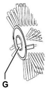
natural_image
Diagram of a mechanical component with radial blades and a central circular feature, labeled 'G' (no text or symbols on the diagram itself)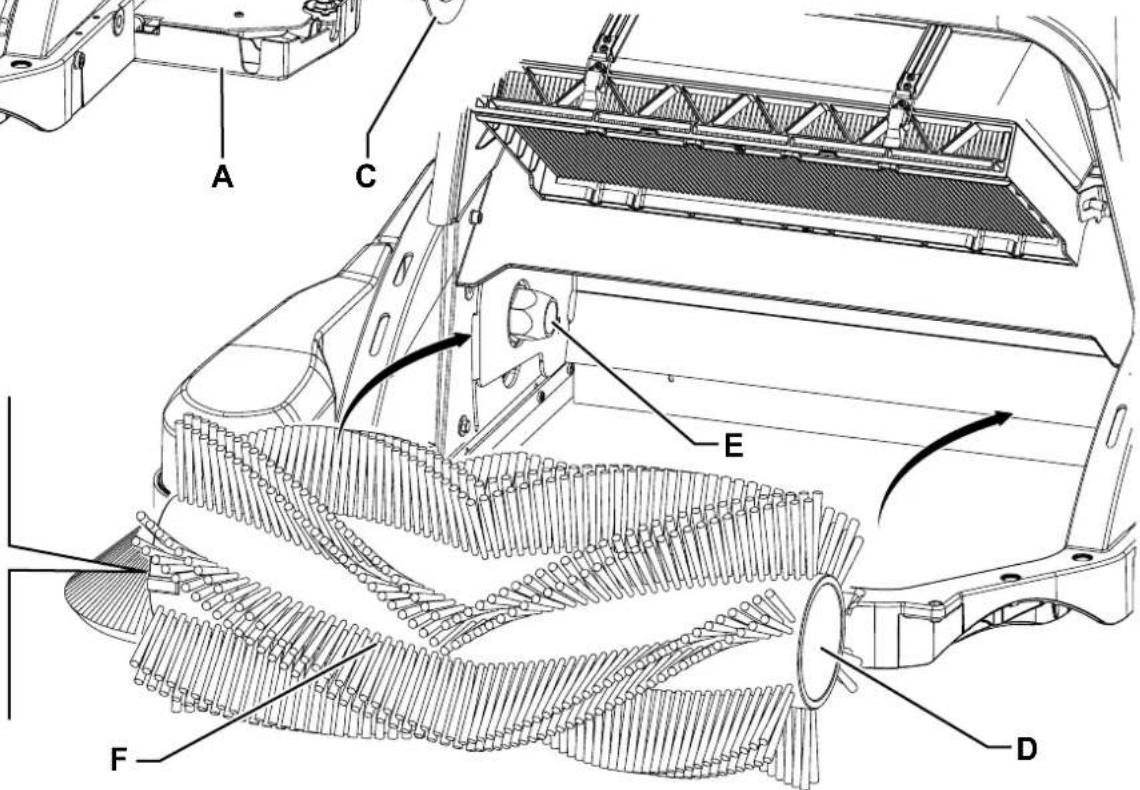
Figure 4
P100819
CONTRÔLE ET RÉGLAGE DE LA HAUTEUR DU BALAI LATÉRAL

REMARQUE
P100825
Figure 9
P100826
Figure 10
NETTOYAGE ET CONTRÔLE DE L'INTÉGRITÉ DU FILTRE A POUSSIÈRE
MANUAL PURPOSE AND CONTENTS 2
TARGET 2
HOW TO KEEP THIS MANUAL....2
DECLARATION OF CONFORMITY 2
IDENTIFICATION DATA....2
OTHER REFERENCE MANUALS....2
SPARE PARTS AND MAINTENANCE....2
CHANGES AND IMPROVEMENTS 2
VISIBLE SYMBOLS ON THE MACHINE....3
SYMBOLS THAT APPEAR ON THIS MANUAL....4
GENERAL INSTRUCTIONS 4
MACHINE DESCRIPTION 6
MACHINE STRUCTURE 6
ACCESSORIES/OPTIONS......8
TECHNICAL DATA....8
WIRING DIAGRAM....9
USE 10
BATTERY CHECK/SETTING ON A NEW MACHINE....11
BEFORE MACHINE START-UP 12
STARTING AND STOPPING THE MACHINE 12
AFTER USING THE MACHINE....13
PUSHING THE MACHINE....13
MACHINE LONG INACTIVITY 13
MAINTENANCE....13
SCHEDULED MAINTENANCE TABLE 14
BATTERY CHARGER CABLE CHECK 14
BATTERY CHARGING 14
MAIN BROOM HEIGHT CHECK AND ADJUSTMENT 15
MAIN BROOM REPLACEMENT 16
SIDE BROOM HEIGHT CHECK AND ADJUSTMENT 17
SIDE BROOM DISASSEMBLY/ASSEMBLY....17
SKIRT CHECK AND ADJUSTMENT 18
DUST FILTER CLEANING AND INTEGRITY CHECK 19
HOPPER POSITION MICROSWITCH OPERATION CHECK....20
FUSE CHECK/REPLACEMENT/RESET 20
BATTERY ELECTROLYTE LEVEL CHECK (FOR WET BATTERIES ONLY) 20
TROUBLESHOOTING 21
SCRAPPING 22
INTRODUCTION

NOTE
The numbers in brackets refer to the components shown in Machine Description chapter.
MANUAL PURPOSE AND CONTENTS
The purpose of this Manual is to provide the operator with all necessary information to use the machine properly, in a safe and autonomous way. It contains information about technical data, safety, operation, storage, maintenance, spare parts and disposal. Before performing any procedure on the machine, the operators and qualified technicians must read this Manual carefully. Contact Nilfisk in case of doubts concerning the interpretation of the instructions and for any further information.
TARGET
This Manual is intended for operators and technicians qualified to perform the machine maintenance.
The operators must not perform procedures reserved for qualified technicians. Nilfisk will not be responsible for damages coming from failure to follow these instructions.
HOW TO KEEP THIS MANUAL
The User Manual must be kept near the machine, inside an adequate case, away from liquids and other substances that can cause damage to it.
DECLARATION OF CONFORMITY
The Declaration of Conformity, supplied with the machine, certifies the machine conformity with the law in force.

NOTE
Two copies of the original declaration of conformity are provided together with the machine documentation.
IDENTIFICATION DATA
The machine serial number and model name are marked on the plate (47).
Product code and year of production are marked on the same plate.
This information is useful when requiring machine spare parts. Use the following table to write down the machine identification data.
MACHINE model
PRODUCT code
MACHINE serial number
OTHER REFERENCE MANUALS
– Electronic Battery Charger Manual (to be considered as integral part of this Manual)
– Spare Parts List (supplied with the machine)
Moreover, the following Manuals are available:
– Service Manual (that can be consulted at Nilfisk Service Centers)
SPARE PARTS AND MAINTENANCE
All necessary operating, maintenance and repair procedures must be performed by qualified personnel or by Nilfisk Service Centers. Only original spare parts and accessories must be used.
Contact Nilfisk for service or to order spare parts and accessories, specifying the machine model, product code and serial number.
CHANGES AND IMPROVEMENTS
Nilfisk constantly improves its products and reserves the right to make changes and improvements at its discretion without being obliged to apply such benefits to the machines that were previously sold.
Any change and/or addition of accessory must be approved and performed by Nilfisk.
This sweeper has been designed to clean (by sweeping and vacuuming) smooth and solid floors, and to collect dust and light debris, in civil and industrial environments, under safe operation conditions by a qualified operator.
CONVENTIONS
Forward, backward, front, rear, left or right are intended with reference to the operator's position, that is to say with the hands on the handlebar (10).
UNPACKING/DELIVERY

CAUTION!
To unpack the machine, carefully follow the instructions on the packing.
Upon delivery carefully check that the machine and its packing have not been damaged during transportation. In case of visible damages, keep the packing and have it checked by the carrier that delivered it. Call the carrier immediately to fill in a damage claim. Check that the machine is equipped with the following features:
- Technical documents:
- Sweeper User Manual (the present document)
• Electronic Battery Charger Manual - Sweeper Spare Parts List
- No. 1 5 A fuse
SAFETY
The following symbols indicate potentially dangerous situations. Always read this information carefully and take all necessary precautions to safeguard people and property.
The operator's cooperation is essential in order to prevent injury. No accident prevention program is effective without the total cooperation of the person responsible for the machine operation. Most of the accidents that may occur in a factory, while working or moving around, are caused by failure to comply with the simplest rules for exercising prudence. A careful and prudent operator is the best guarantee against accidents and is essential for successful completion of any prevention program.
VISIBLE SYMBOLS ON THE MACHINE

WARNING!
Carefully read all the instructions before performing any operation on the machine.

WARNING!
Do not wash the machine with direct or pressurised water jets.

WARNING!
Do not use the machine on slopes with a gradient exceeding the specifications.
WARNING!
Moving parts.
SYMBOLS THAT APPEAR ON THIS MANUAL

DANGER!
It indicates a dangerous situation with risk of death for the operator.

NOTE
It indicates a remark related to important or useful functions.

WARNING!
It indicates a potential risk of injury for people or damage to objects.

CONSULTATION
It indicates the necessity to refer to the User Manual before performing any procedure.

CAUTION!
It indicates a caution or a remark related to important or useful functions. Pay careful attention to the paragraphs marked by this symbol.
GENERAL INSTRUCTIONS
Specific warnings and cautions to inform about potential damages to people and machine are shown below.

DANGER!
— Before performing any cleaning, maintenance, repair or replacement procedure, remove the ignition key.
- This machine must be used by properly trained operators only.
- Do not wear jewels when working near electrical components.
— Do not work under the lifted machine without supporting it with safety stands.
- Do not operate the machine near toxic, dangerous, flammable and/or explosive powders, liquids or vapours: This machine is not suitable for collecting dangerous powders.
- Keep the batteries away from sparks, flames and incandescent material. Explosive gases are released when charging the batteries.
- If the machine is equipped with lead (WET) batteries, battery charging produces highly explosive hydrogen gas. Charge the batteries in well-ventilated areas and away from naked flames.
- When lead batteries (WET) are installed, do not tilt the machine for more than 30^ from the horizontal plane to prevent the highly corrosive acid from leaking out of the batteries. When the machine is to be tilted to perform maintenance procedures, remove the batteries.

WARNING!
Carefully read all the instructions before performing any maintenance/repair procedure.
Before using the battery charger, ensure that frequency and voltage values, indicated on the machine serial number plate, match the electrical mains voltage.
- Do not pull or carry the machine by the battery charger cable and never use the battery charger cable as a handle. Do not close a door on the battery charger cable, or pull the battery charger cable around sharp edges or corners. Do not run the machine on the battery charger cable.
- Keep the battery charger cable away from heated surfaces.
- Do not use the machine if the battery charger cable or plug is damaged. If the machine is not working as it should, has been damaged, left outdoors or dropped into water, return it to the Service Center.
Before performing any maintenance procedure, disconnect the battery charger cable from the electrical mains to avoid any risk of fire, electric shock or injuries.

WARNING!
- Do not smoke while charging the batteries.
- This machine is not intended for use by persons (including children) with reduced physical, sensory or mental capabilities, or lack of experience and knowledge, unless they have been given supervision or instruction concerning use of the machine by a person responsible for they safety. Children should be supervised to ensure that they do not play with the machine.
- Close attention is necessary when used near children.
- Use only as shown in this Manual. Use only Nilfisk's recommended accessories.
- Check the machine carefully before each use, always check that all the components have been assembled before use. If the machine is not perfectly assembled it can cause damages to people and properties.
Take all necessary precautions to prevent hair, jewels and loose clothes from being caught by the machine moving parts.
- To avoid any unauthorised use of the machine, remove the ignition key.
- Do not leave the machine unattended without being sure that it cannot move independently.
- Do not use the machine on slopes with a gradient exceeding the specifications.
- Do not tilt the machine more than the angle indicated on the machine itself, in order to prevent instability.
– Use only brooms supplied with the machine or those specified in the User Manual. Using other brooms could reduce safety.
— Before using the machine, close all doors and/or covers, as indicated in the User Manual.
- Do not wash the machine with direct or pressurised water jets, or with corrosive substances.
- Use the machine only where a proper lighting is provided.
While using this machine, take care not to cause damage to people or objects.
- Do not bump into shelves or scaffoldings, especially where there is a risk of falling objects.
- Do not lean liquid containers on the machine, use the relevant can holder.
- The storage temperature must be between 0^ and +40^ .
- The machine working temperature must be between 0^ and +40^ .
- The humidity must be between 30% and 95% .
- Always protect the machine against the rain and bad weather, both under operation and inactivity condition. Store the machine indoors, in a dry place. This machine must be used in dry conditions, it must not be used or kept outdoors in wet conditions.
- Do not use the machine as a means of transport, or for pushing/towing.
- Do not allow the brooms to operate while the machine is stationary to avoid damaging the floor.
- The machine maximum capacity is 30 kg (the maximum weight of waste).
– In case of fire, use a powder fire extinguisher, not a water one.
- This machine cannot be used on roads or public streets.
- Do not tamper with the machine safety guards.
– Follow the routine maintenance procedures scrupulously.
- Do not allow any object to enter into the openings. Do not use the machine if the openings are clogged. Always keep the openings free from dust, hairs and any other foreign material which could reduce the air flow.
- Do not remove or modify the plates affixed to the machine.
– In case of machine malfunctions, ensure that these are not due to lack of maintenance. If necessary, request assistance from the authorised personnel or from an authorised Service Center.
- If parts must be replaced, require ORIGINAL spare parts from an Authorised Dealer or Retailer.
- To ensure machine proper and safe operation, the scheduled maintenance shown in the relevant chapter of this Manual, must be performed by the authorised personnel or by an authorised Service Center.
- The machine must be disposed of properly, because of the presence of toxic-harmful materials (batteries, oils, etc.), which are subject to standards that require disposal in special centres (see the Scrapping chapter).
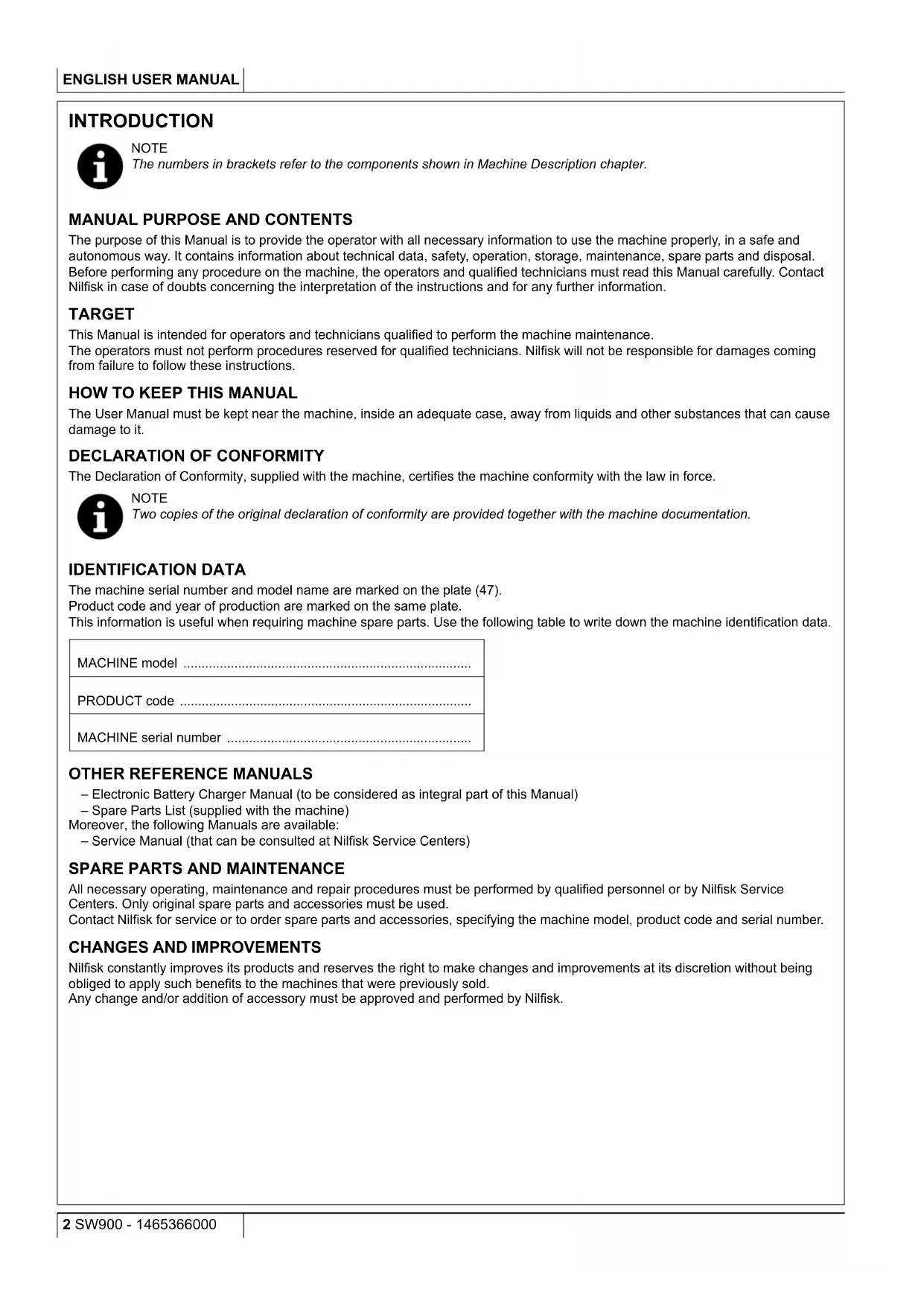
MACHINE DESCRIPTION
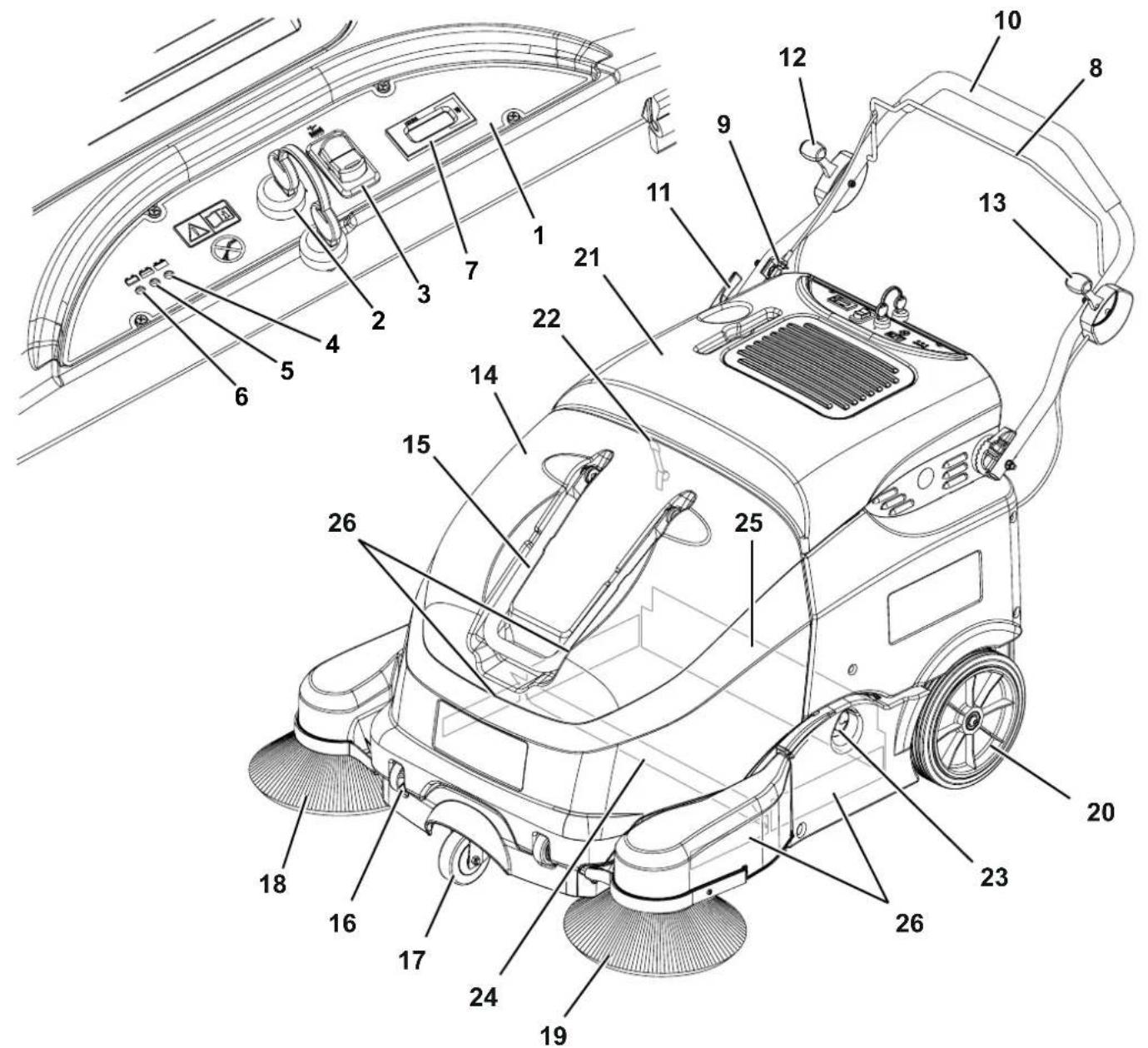
MACHINE STRUCTURE
- Control panel
-
Ignition key:
-
Position "0": The machine is off and all functions are disabled
-
Position "I": The machine is on and all functions are enabled
-
Electrical filter shaker switch
- Charged battery LED (green)
- Semi-discharged battery LED (yellow)
- Discharged battery LED (red)
- Hour counter
- Drive control lever
- Drive system control adjuster
- Handlebar
- Handlebar tilting adjusting lever
-
Right side broom lifting/lowering lever
-
Left side broom lifting/lowering lever (optional)
- Hopper
- Hopper transport handle
- Hopper wheels
- Front pivoting wheel
- Right side broom
- Left side broom (optional)
- Rear driving wheels
- Battery and main motor hood
- Front hood latch
- Left door opening/closing knob
- Front skirt
- Rear skirt
- Side skirts
P100813
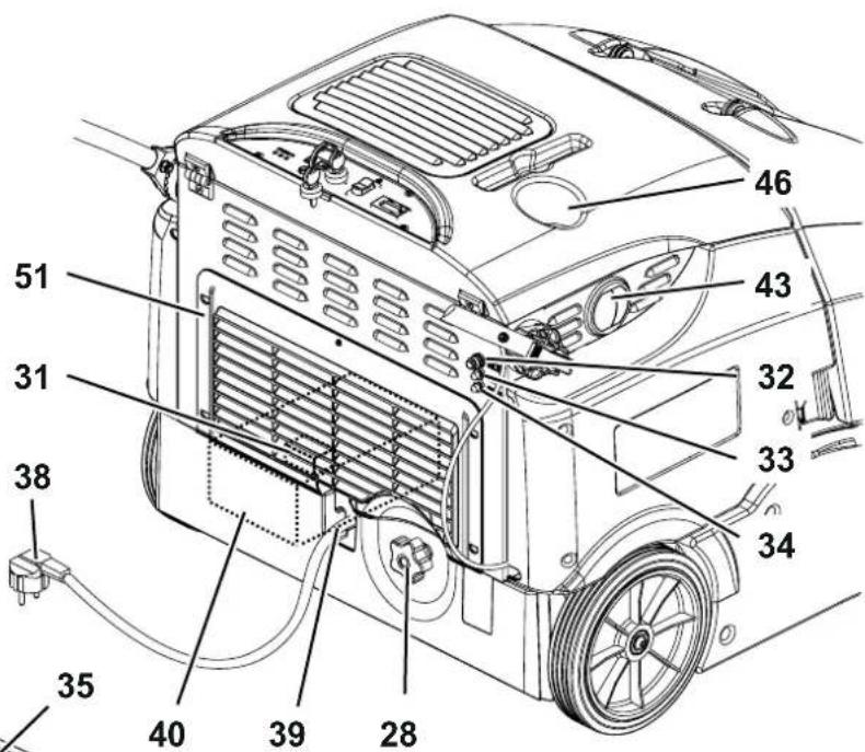
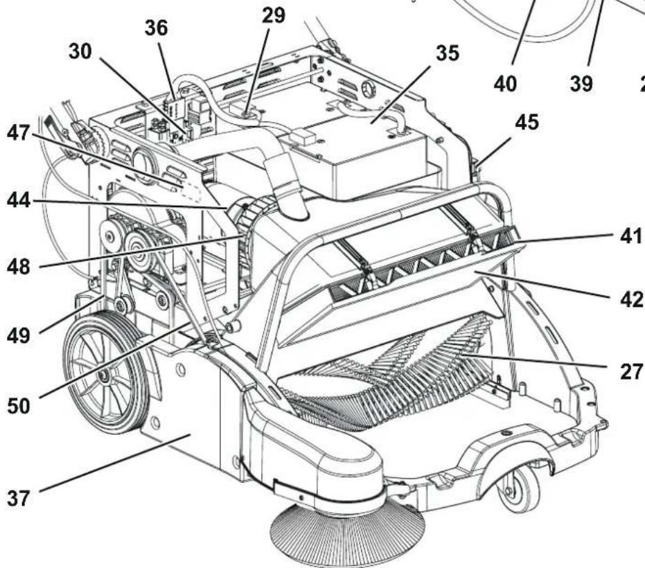
MACHINE STRUCTURE (Continues)
- Main broom
- Main broom height adjusting knob
- Battery fuse
- Filter shaker fuse
- Battery charger fuse
- Main motor circuit breaker
- Right side broom motor circuit breaker
- Left side broom motor circuit breaker (optional)
- Batteries
- Battery connector
- Right door
-
Battery charger cable
-
Battery charger cable housing
- Electronic battery charger
- Dust filter
- Pre-filter (optional)
- "Wet by-pass" port
- Main motor
- Hopper position microswitch
- Can holder
- Serial number plate/technical data/conformity certification
- Vacuum fan
- Driving belt
- Main broom belt
- Rear grid
P100814
ACCESSORIES/OPTIONS
In addition to the standard components, the machine can be equipped with the following accessories/options, according to the machine specific use:
- Left side broom
– Main and side brooms with harder or softer bristles
– Paper dust filter - Pre-filter
- Manual filter shaker
- Non-marking skirts
For further information concerning the optional accessories, contact an authorised Retailer.
TECHNICAL DATA
| Model SW900 B | ||
| Cleaning width with one side broom 825 mm | ||
| with two side brooms 1,050 mm | ||
| Main broom size (length x diameter) 600 x 265 mm | ||
| Side broom diameter 315 mm | ||
| Theoretical working capacity with one side broom 3715 m | ^2/h | |
| with two side brooms 4725 m | ^2/h | |
| Hopper capacity 60 litres | ||
| maximum transportable weight | 30 kg | |
| Filter | cleaning system | Electrical filter shaker |
| area | 1.9 m^2 | |
| filtering capacity | 5-10 μm | |
| Power Lead batteries for cyclic use / traction | 12V (100 - 200 Ah C5) | |
| Main motor | power (drive/main broom/vacuum system) | 680 W |
| Main broom | speed | 420 rpm |
| Side broom | motor power | 40 W |
| speed | 100 rpm | |
| Drive | forward speed | 4.5 km/h |
| Maximum gradient when working | 2 % | |
| Filter shaker motor | 12 W | |
| Total absorbed power 0.8 kW | ||
| Working autonomy | 3 h | |
| Size(length x width x height) | machine running | 1,390 x 870 x 1,100 mm |
| machine with folded handlebar | 1,050 x 870 x 840 mm | |
| machine with two side brooms | 1,390 x 950 x 1,100 mm | |
| battery compartment | 327 x 230 x 380 mm | |
| Weight | kerb weight without batteries | 82 Kg |
| total kerb weight (*) | 143 Kg | |
| gross vehicle weight (GVW) | 176 Kg | |
| Wheel specific pressure on the floor (front - rear wheels, in running conditions) | 2.1 - 0.5 N/ mm^2 | |
| Sound pressure level at workstation (ISO 11201, ISO 4871, EN 60335-2-72) (LpA) | 70 ± 3 dB(A) | |
| Machine sound pressure level (ISO 3744, ISO 4871, EN 60335-2-72) (LwA) | 84 dB(A) | |
| IP protection class | X3 | |
| U-turn space | 1550 mm | |
| Vibration level at the operator's arms (ISO 5349-1) (**) | < 2.5 m/ s^2 | |
(*) With batteries and empty hopper.
(**) Under normal working conditions, on a level asphalt surface.
Machine material composition and recyclability
| Type Recyclable | percentage | SW900 B weight percentage |
| Aluminium 100 % 2.4 % | ||
| Electric motors - various 29 % 11.8 % | ||
| Ferrous materials 100 % 39.4 % | ||
| Wiring harnesses 80 % 1.8 % | ||
| Liquids 100 % 0.0 % | ||
| Plastic - non-recyclable material 0 % 9.4 % | ||
| Plastic - recyclable material 100 % 27.1 % | ||
| Polyethylene | 92 % 5.9 % | |
| Rubber | 20 % 2.4 % | |
| Cardboard - paper - wood | 100 % 28.6 % |
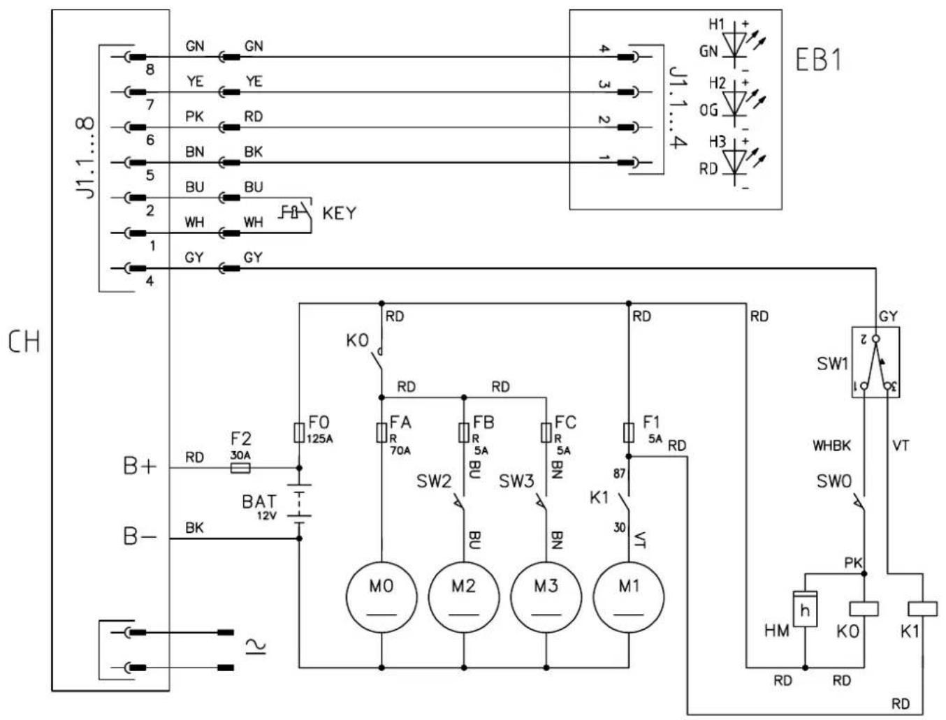
WIRING DIAGRAM
Key
| BAT | 12 V batteries |
| CH | Battery charger |
| EB1 | Electronic board LED |
| F0 | System protection fuse (125 A) |
| F1 | Filter shaker fuse (5 A) |
| F2 | Battery charger fuse (30 A) |
| FA | Main motor circuit breaker (70 A) |
| FB | Right side broom circuit breaker (5 A) |
| FC | Left side broom circuit breaker (5 A) (optional) |
| HM | Hour counter |
| K0 | Main motor electromagnetic switch |
| K1 | Filter shaker relay |
| KEY | Ignition key |
| M0 | Main motor |
| M1 | Filter shaker motor |
| M2 | Right side broom motor |
| M3 | Left side broom motor (optional) |
| SW0 | Hopper microswitch |
| SW1 | Filter shaker switch |
| SW2 | Right side broom microswitch |
| SW3 | Left side broom microswitch (optional) |
Colour codes
| BK | Black |
| BU | Blue |
| BN | Brown |
| GN | Green |
| GY | Grey |
| OG | Orange |
| PK | Pink |
| RD | Red |
| VT | Violet |
| WH | White |
| YE | Yellow |
P100815
USE

WARNING!
On some points of the machine there are some adhesive plates indicating:
- DANGER
- WARNING
- CAUTION
- CONSULTATION
While reading this Manual, the operator must pay particular attention to the symbols shown on the plates (see the Visible Symbols On The Machine paragraph).
Do not cover these plates for any reason and immediately replace them if they are damaged.
BATTERY CHECK/SETTING ON A NEW MACHINE

WARNING!
The electric components of the machine can be seriously damaged if the batteries are either improperly installed or connected. The batteries must be installed by qualified personnel only.
According to the type of batteries (WET or GEL-AGM), set the machine battery charger.
Check the batteries for damage before installation.
Disconnect the battery connector and the battery charger plug.
Handle the batteries with great care.
Install the battery terminal protection caps supplied with the machine.
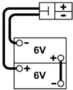
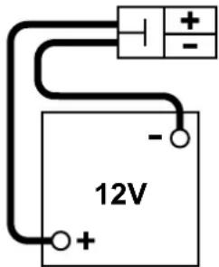
The machine requires one 12 V battery, or two 6 V batteries connected according to the diagram in Figure 1.
The machine can be supplied in one of the following configurations:
a) WET or GEL batteries already installed on the machine
b) Without batteries
According to machine configuration, proceed as follows.
a) WET or GEL-AGM batteries already installed on the machine
- Disengage the front latch (22) and open the battery and main motor hood (21), then check that the batteries are connected to the machine with the connector (36).
- Close the battery and main motor hood (21) and engage the front latch (22).
- Insert the ignition key (2) on the control panel and turn it to "I" without pulling the drive control lever (8).
If the green LED (4) turns on, the batteries are ready to be used.
If the yellow or red LED (5 or 6) turns on, the batteries must be charged (see the procedure in Maintenance chapter).
b) Without batteries
- Buy appropriate batteries (see the Technical Data paragraph and the diagram in Figure 1).
For battery choice and installation, apply to qualified battery Retailers. - Disengage the front latch (22) and open the battery and main motor hood (21).
- Ensure that the battery connector (36) is disconnected.

WARNING!
The installed batteries may require a specific charging algorithm: to set the most appropriate charging algorithm for the installed batteries, always contact a qualified Nilfisk Service Center.
- Carefully lift the batteries to the relevant compartment, then place them as shown in Figure 1.
- Route and install the battery cable as shown in the diagrams in Figure 1, then carefully tighten the nut on each battery terminal.
- Place the protection cap on each terminal, then connect the battery connector (36).
- Close the battery and main motor hood (21) and engage the front latch (22).
- Charge the batteries (see the procedure in Maintenance chapter).
BATTERY PLUG
BATTERY PLUG
P100816
Figure 1
BEFORE MACHINE START-UP
- Make sure that there are no open doors/hoods and that the machine is in normal operating conditions.
- If the machine has not been used after being transported, check that all the blocks used for the transportation have been removed.
- Check that side and main brooms are installed, otherwise install them (see the procedure in Maintenance chapter).
- Adjust the handlebar (10) as necessary, by using the lever (11). When the adjustment is completed, close the lever.
STARTING AND STOPPING THE MACHINE
Starting the machine
- Insert the ignition key (2) on the control panel and turn it to "I" without pulling the drive control lever (8).
During the first 3 seconds, the battery LEDs (4, 5 and 6) flashing indicates the type of battery installed. Then, if the battery charge is sufficient, the main motor (44) turn on the main broom (27) and the vacuum fan (48).
If the green LED (4) turns on, the batteries are ready to be used.
If the yellow or red LED (5 or 6) turns on, the batteries must be charged (see the procedure in Maintenance chapter).

WARNING!
The machine cannot be started when the hopper (14) is not its position. A safety system prevents it from starting.
- Lower the side brooms (18) and (19, optional), by pulling the levers (12) and (13, optional) backwards.

NOTE
The side brooms turn on when lowered and can be lowered and lifted even when the machine is moving.
- Start sweeping by grasping the handlebar (10) and pulling the drive control lever (8) gradually.
Stopping the machine
- To stop the machine, release the drive control lever (8) completely.
- To stop the side brooms (18) and (19, optional), pull the levers (12) and (13, optional) onwards.
- To turn off the main broom (27) and the vacuum fan (48), turn the ignition key (2) to "0".
- Make sure that the machine cannot move independently.
MACHINE OPERATION
- Drive the machine to the work area as shown in the previous paragraph.
- Avoid stopping for a long time with the machine in the same position and the brooms turning: this could create unwanted marks on the floor.
- For machine proper operation, the dust filter (41) must be as clean as possible. For cleaning it while sweeping, turn on the filter shaker by pressing the switch (3) for a few seconds. During this procedure the main motor and all functions are automatically cut-off.

NOTE
Repeat the filter shaking procedure at least every 10 minutes. This interval can change depending on the dustiness of the area to be cleaned.

NOTE
When the dust filter is clogged and/or the hopper (14) is full, the machine cannot collect dust and debris anymore.
-
When operating on wet floors, open the "wet by-pass" port (43) to avoid damaging the dust filter. When operating on dry floors, close the "wet by-pass" port (43) to restore proper vacuuming.
-
The hopper (14) should be emptied after each working cycle and whenever it is full.

NOTE
When the hopper is full, the machine cannot collect dust and debris anymore.
HOPPER DUMPING
- Stop the machine and turn the ignition key (2) to "0".
- Remove the hopper (14) by using the transport handle (15) and the wheels (16) to drag it at the waste collection centre, then empty it.
- Reinstall the hopper on the machine.
- The machine is ready to start sweeping again.

NOTE
When the hopper is removed, all machine functions are disabled.
AFTER USING THE MACHINE
After working, before leaving the machine, perform the following procedures.
- Turn on the filter shaker with the switch (3).
- Turn the ignition key (2) to "0" to stop the machine.
- Empty the hopper (14) (see the procedure in the previous paragraph).
– Lift the side brooms (18) and (19, optional), by pulling the levers (12) and (13, optional) onwards. - Make sure that the machine cannot move independently.
– Charge the batteries (see the procedure in Maintenance chapter).
PUSHING THE MACHINE
The machine can be pushed both with the ignition key (2) to "0" and to "1".
MACHINE LONG INACTIVITY
If the machine is not going to be used for more than 30 days, proceed as follows:
- Perform the procedures shown in After Machine Use paragraph.
- Check that the machine storage area is dry and clean.
- Disconnect the battery connector (36).
- Slightly lift the machine so that the skirts, the main broom and the wheels do not touch the ground.
MAINTENANCE
The lifespan of the machine and its maximum operating safety are ensured by correct and regular maintenance.
The following table provides the scheduled maintenance. The intervals shown may vary according to particular working conditions, which are to be defined by the person in charge of the maintenance.
All scheduled or extraordinary maintenance procedures must be performed by qualified personnel, or by an authorised Service Center.
This Manual describes only the easiest and most common maintenance procedures.
For other maintenance procedures shown in the Scheduled Maintenance Table, refer to the Service Manual that can be consulted at any Service Center.

WARNING!
To perform maintenance procedures, the machine must be off, the ignition key removed, and, if necessary, the batteries must be disconnected.
Read carefully the instructions in the Safety chapter before performing any maintenance procedure.
SCHEDULED MAINTENANCE TABLE
| Procedure Upon delivery | Every 10 hours | Every 50 hours | Every 200 hours | Every 400 hours | |
| Battery charging | (1) | ||||
| Battery (WET) fluid level check | |||||
| Battery charger cable check | |||||
| Dust filter cleaning and integrity check (2) | |||||
| Side and main broom height check and adjustment | |||||
| Skirt height and operation check | |||||
| Filter gasket check | |||||
| Electrical filter shaker operation check (*) | |||||
| Driving belt check/adjustment: drive system, main broom. (*) | |||||
| Hopper position microswitch operation check | |||||
| Driving belt replacement: drive system, main broom. (*) | |||||
| Motor carbon brush check or replacement (*) |
(*) For the relevant procedure, refer to the Service Manual.
(1) Daily or after using the machine.
(2) Or before use.
BATTERY CHARGER CABLE CHECK
Carefully check the battery charger cable (38) and the relevant plug for wear, cuts, cracks or other damages. If the battery charger cable or the relevant plug is damaged, contact the Nilfisk Service Center.
BATTERY CHARGING

CAUTION!
Charge the batteries when the yellow (5) or red LED (6) turns on, or at the end of each cleaning cycle. Keeping the batteries charged make their life last longer.

WARNING!
When the batteries are discharged, charge them as soon as possible, as that condition makes their life shorter.

WARNING!
If the machine is equipped with lead (WET) batteries, battery charging produces highly explosive hydrogen gas. Charge the batteries in well-ventilated areas and away from naked flames.
Do not smoke while charging the batteries.
While charging the batteries always keep the hood open.

WARNING!
Pay careful attention when charging WET batteries as there may be battery fluid leakages. The battery fluid is corrosive. If it comes in contact with skin or eyes, rinse thoroughly with water and consult a physician.
- Drive the machine on a level floor. Make sure that the machine cannot move independently.
- Turn the ignition key (2) to "0".
- Connect the cable (38) of the electronic battery charger (40) to the electrical mains.

WARNING!
The mains voltage and frequency must match the electronic battery charger values shown on the machine serial number plate (47).

NOTE
When the electronic battery charger is connected to the electrical mains, all machine functions are automatically disabled.
- When the green LED (4) turns on, the batteries are charged.
For further information about the battery charger operation (40), see the Battery Charger Manual. - Disconnect the electronic battery charger cable (38) from the electrical mains and place it in its housing (39) on the machine.
- Now the machine is ready to be used.
MAIN BROOM HEIGHT CHECK AND ADJUSTMENT

NOTE
Brooms with harder or softer bristles are available. This procedure is applicable to all types of brooms.
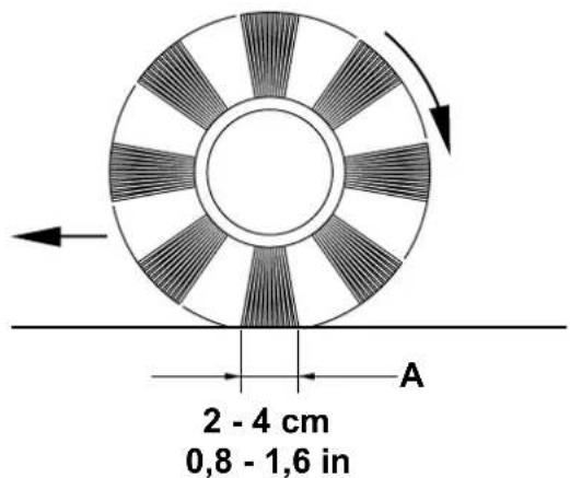
Check
- Check the main broom distance from the ground, according to the following procedure:
- Drive the machine on a level floor.
- Keep the machine stationary and turn on the main broom for a few seconds.
- Stop the main broom, then move the machine and turn it off.
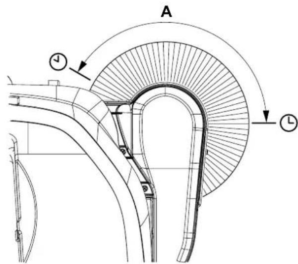
- Check that the main broom print (A, Fig. 2), along its length, is 2 to 4 cm wide.
- If the print (A) is not within specifications, adjust the broom height.
Adjustment
- Turn the ignition key (2) to "0".
- Turn the knob (B, Fig. 3) as shown below:
• to increase the print width, turn the knob counterclockwise
• to decrease the print width, turn the knob clockwise

NOTE
The knob can be used both to adjust the print and to adjust the broom according to the bristle wear.
- Perform step 1 again to check that the main broom is at the correct distance from the ground.
- When the broom is too worn to be adjusted, replace it as shown in the next paragraph.

CAUTION!
If the main broom print is excessive (larger than 4 cm), the machine regular operation is affected and the moving parts or electrical components can overheat, thus reducing machine life.
Pay careful attention when performing the above-mentioned checks, and always use the machine according to the indicated conditions.
P100817
Figure 2
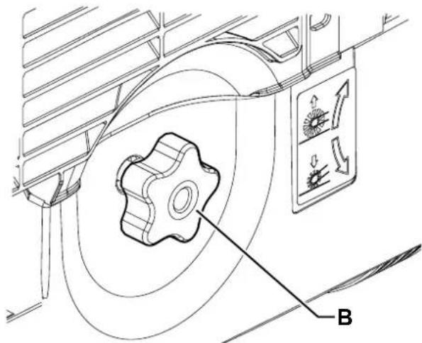
P100818
Figure 3
MAIN BROOM REPLACEMENT

CAUTION!
It is advisable to wear protective gloves when replacing the main broom because there can be sharp debris between the bristles.
- Drive the machine on a level floor.
- Turn the ignition key (2) to "0".
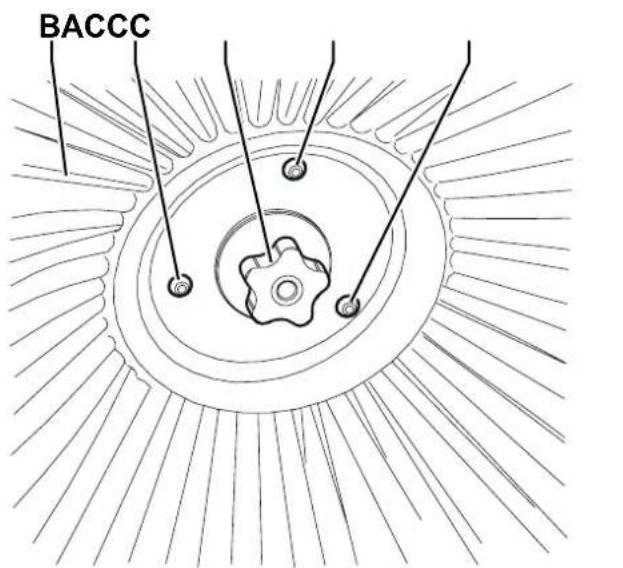
- Turn the main broom height adjusting knob (28) fully clockwise.
- Remove the hopper (14).
- Turn the knob (23) and open the left door (A, Fig. 4).
- Loosen the knobs (B) and remove the main broom cover (C) by slightly turning it counter-clockwise.
- Remove the main broom (D) from the front side of the machine.
- Check that the drive hub (E) is free from dirt or foreign materials (cords, rags, etc.) accidentally rolled up.
- Place the new main broom with the bristles rows (F) bent as shown in the figure.
- Install the new main broom on the front side of the machine, and ensure that the mesh (G) properly fits into the relevant drive hub (E).
- Install the main broom cover (C) and tighten the knobs (B).
- Close the left door (A).
- Adjust the main broom height as shown in the previous paragraph.
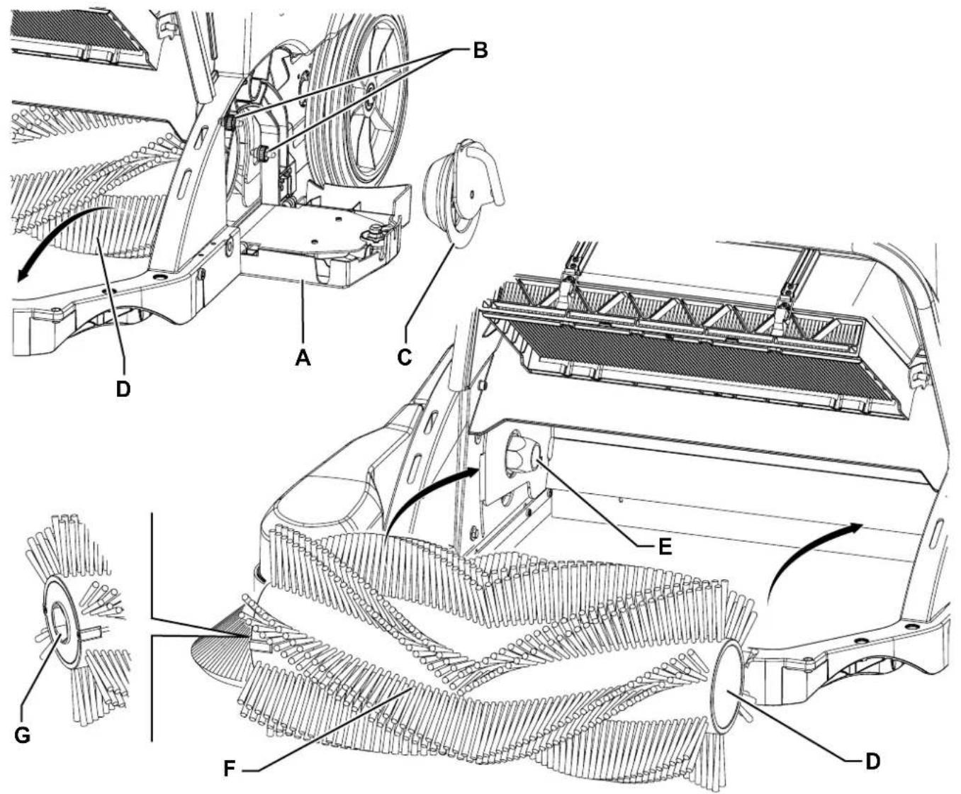
Figure 4
P100819
SIDE BROOM HEIGHT CHECK AND ADJUSTMENT

NOTE
Brooms with harder or softer bristles are available. This procedure is applicable to all types of brooms.

NOTE
This procedure is applicable to both the right side broom and left side broom (optional).
Check
- Drive the machine on a level floor.
- Turn the ignition key (2) to "I".
- Lower the side broom with the lever (12).
- The proper side broom height is reached when the bristles touch the floor along a circle arc as shown (A, Fig. 5). If the print (A) is not within specifications, adjust the broom height.
Adjustment
- Turn the ignition key (2) to "0".
- Loosen the nut (C, Fig. 6) under the cover (B) and turn the screw (D) clockwise or counter-clockwise to increase or decrease the side broom height. Then lock the screw with the nut.
- Perform step 4 again to check that the side broom is at the correct distance from the ground.
- When the broom is too worn to be adjusted, replace it as shown in the next paragraph.

CAUTION!
If the side broom print is excessive, the machine regular operation is affected and the moving parts or electrical components can overheat, thus reducing machine life.
P100820
Figure 5
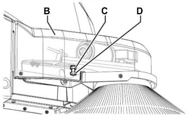
P100821
Figure 6
SIDE BROOM DISASSEMBLY/ASSEMBLY

CAUTION!
It is advisable to wear protective gloves when replacing the side broom because there can be sharp debris between the bristles.

NOTE
This procedure is applicable to both the right side broom and left side broom (optional).
- Drive the machine on a level floor.
- Turn the ignition key (2) to "0".
- Loosen the knob (A, Fig. 7) inside the side broom, then remove the broom (B) by disengaging it from the three pins (C).
- Install the new broom on the machine engaging it on the pins (C), then tighten the knob (A).
- Adjust the height of the new broom according to the procedure shown in the previous paragraph.
P100822
Figure 7
SKIRT CHECK AND ADJUSTMENT
- Drive the machine on a level floor that is suitable for checking the skirt height. Make sure that the machine cannot move independently.
- Turn the ignition key (2) to "0".
- Remove the hopper (14).
- Remove the main broom (27) as shown in the relevant paragraph.
Side Skirt Check
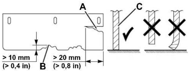
- Check the side skirts (26) for integrity. Replace the skirts when they have cuts (A, Fig. 8) larger than 20 mm or cracks/tears (B) larger than 10 mm (for skirt replacement, refer to the Service Manual).
- Check that the height of the side skirts (26) is as shown in the figure (C), the side skirts must touch the floor all along their length.
- If necessary, adjust the skirts according to the following procedure.
Side Skirt Adjustment
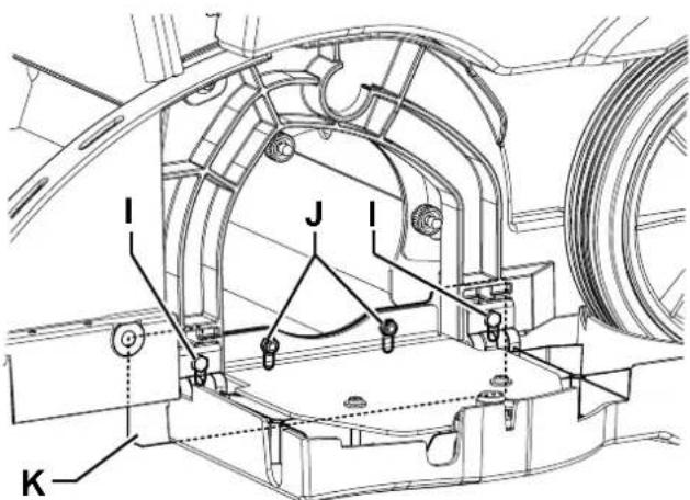
- Remove the right door (37) to reach the nuts (D, Fig. 9).
- Loosen the nuts (D) and the screw (E), then adjust the height of the right side skirt (F) by using the slots of the mounting holes.
- Loosen the screws (G) and adjust the height of the right side recovery skirt (H) by using the slots of the mounting holes.
- Loosen the screws (I) and the nuts (J), then adjust the height of the left side skirt (K) by using the slots of the mounting holes.
- After that, tighten the screws and nuts.

NOTE
The adjustment procedure is applicable to both the right side recovery skirt (H) and left side recovery skirt (optional).
Front Skirt Check and Rear Skirt Check/Adjustment
- On the hopper (14), check the front skirt (24) for integrity.
- Check the rear skirt (25) for integrity.
- Replace the skirts when they have cuts (A, Fig. 8) larger than 20 mm or cracks/tears (B) larger than 10 mm (for skirt replacement, refer to the Service Manual).
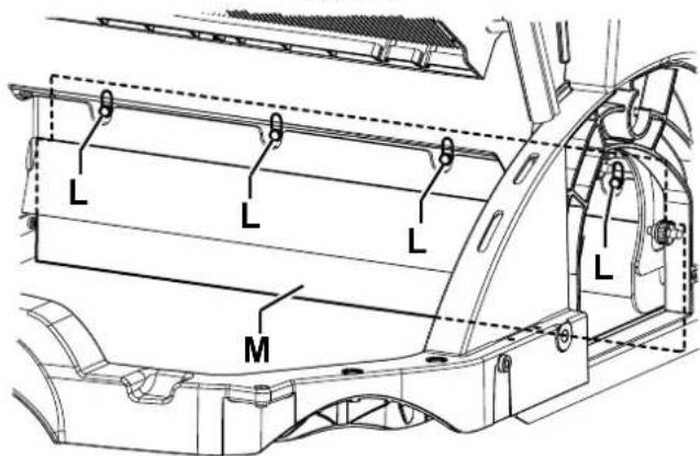
- Check that the height of the rear skirt (25) is as shown in the figure (C), the skirt must touch the floor all along its length.
- If necessary, loosen the screws (L, Fig. 10) and adjust the height of the skirt (M) by using the slots of the mounting holes.
- When the adjustment is completed, tighten the screws (L).
- Assemble the components in the reverse order of disassembly.

NOTE
The front skirt (24) on the hopper does not require to be adjusted.
P100823
Figure 8
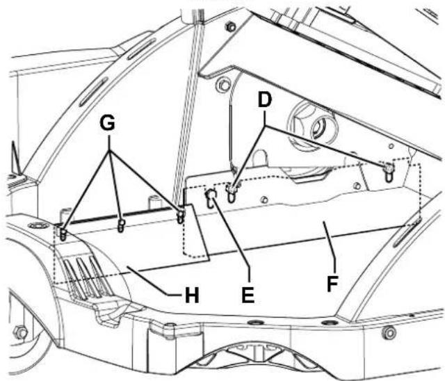
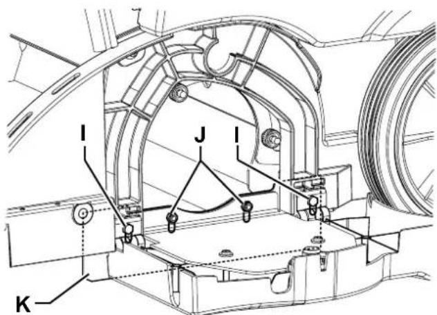
Figure 9
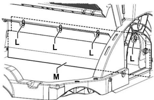
P100826
Figure 10
DUST FILTER CLEANING AND INTEGRITY CHECK
The dust filter must be regularly cleaned to maintain the efficiency of the vacuum system. Follow the recommended filter service intervals for the longest filter life.

WARNING!
Wear safety glasses when cleaning the filter.
Do not puncture the filter.
Clean the filter in a well-ventilated area.
Wear appropriate dust mask to avoid breathing in dust.

NOTE
Besides the standard polyester filter, paper filter is also available.
- Drive the machine on a level floor and ensure that it cannot move.
- Turn the ignition key (2) to "0".
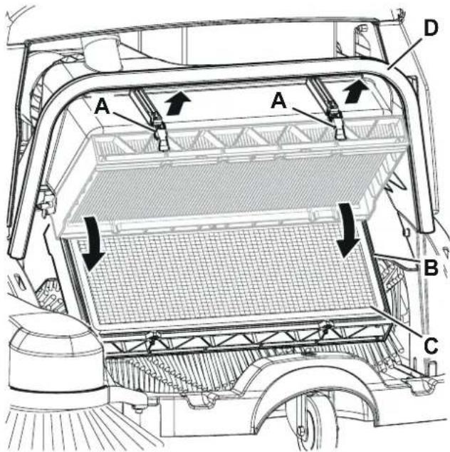
- Remove the hopper (14).
- Disengage the levers (A, Fig. 11) and turn the filter holder (B) downwards.
- Remove the dust filter (C).
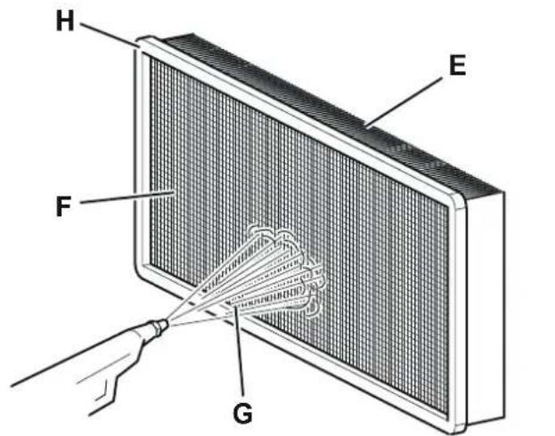
- In an outdoor area, clean the dust filter by shaking it on a level and clean surface, tapping the side (E, Fig. 12) opposite to the wire gauze (F).
- Complete the cleaning procedure by using compressed air (G) at maximum 6 Bar, blowing only from the side protected by the wire gauze (F). Moreover, according to the filter type, observe the following cautions:
- Polyester filter (standard): For a better cleaning, it is allowed to wash the filter with water and non-lathering detergents. This provides better quality cleaning but reduces the life of the filter, which will have to be replaced more frequently. The use of inadequate detergents can damage the filter.
- Paper filter (optional): Do not use water or detergents to clean it, otherwise it can be damaged.
- Check the filter body for tears. Clean the gasket (H) along its perimeter and check it for integrity. If necessary, replace the filter.
- If necessary, clean the filter compartment rubber gasket (D, Fig. 11) along its perimeter and check it for integrity. If necessary, replace it.
- Assemble the components in the reverse order of disassembly.
Pre-filter Cleaning (optional)
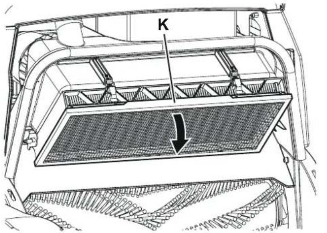
- Perform steps 1 to 3.
- Remove the pre-filter (K, Fig. 13) and clean it with compressed air at maximum 6 Bar.
- Assemble the components in the reverse order of disassembly.
P100827
Figure 11
P100828
Figure 12
P100829
Figure 13
- Turn off the machine and remove the hopper (14).
- Try to start the machine by turning the ignition key (2) to "I". The machine should not start. Turn the ignition key (2) to "0".
- Reinstall the hopper (14).
- If the machine keeps operating when the hopper (14) has been removed, contact an authorised Service Center or Retailer immediately.
FUSE CHECK/REPLACEMENT/RESET
- Drive the machine on a level floor. Make sure that the machine cannot move independently.
- Turn the ignition key (2) to "0".
Fuse Check
- Check one of the following fuses for deactivation:
(32): Main motor fuse FA (70 A).
(33): Right side broom motor fuse FB (5 A)
(34): Left side broom motor fuse FC (5 A) (optional)
Reset any deactivated fuse, when the component that caused deactivation has fully cooled down.
Fuse check/replacement
- Disengage the front latch (22) and open the battery and main motor hood (21).
- Disconnect the battery connector (36).
- Check/replace the relevant fuse among the following:
(29): Battery fuse F0 (125 A).
(30): Electrical filter shaker fuse F1 (5 A).
Check/replace the battery charger fuse (31) as follows:
-
Open the rear grid (51) by loosening the mounting screws.
-
Open the fuse holder and check/replace the F2 fuse (30 A).
Reassembly
- Connect the battery connector (36).
- Close the battery and main motor hood (21) and engage the front latch (22).
- Close the rear grid (51) and tighten the screw.
BATTERY ELECTROLYTE LEVEL CHECK (FOR WET BATTERIES ONLY)
- Disengage the front latch (22) and open the battery and main motor hood (21).
- Check the level of electrolyte inside the batteries (35). If necessary, top up through the caps.
- Close all the battery caps (35).
- Close the battery and main motor hood (21) and engage the front latch (22).
- If necessary, charge the batteries as shown in the relevant paragraph.
TROUBLESHOOTING
| Trouble Possible cause Remedy | ||
| The machines functions are not enabled when turning the ignition key to “I”. | The battery connector is disconnected. | Open the hood and connect the battery connector. |
| The hopper is not in its proper position. Place the hopper properly. | ||
| The main motor circuit breaker (FA) is open. | Wait for the main motor to cool down, then reset the fuse by pressing the relevant push-button. | |
| The electronic battery charger is connected to the electrical mains. | Disconnect the electronic battery charger from the electrical mains. | |
| The hopper microswitch is broken. Replace the microswitch. (*) | ||
| The side broom does not operate. | The fuse (FB) or (FC) (optional) is open. | Wait for the side broom motor to cool down, then reset the fuse by pressing the relevant push-button. |
| The side broom microswitch is faulty. | Replace the relevant side broom microswitch. (*) | |
| The machine collects little debris/dust. | The dust filter is clogged. | Clean the dust filter by using the filter shaker or by disassembling it. |
| The hopper is full. Empty the hopper. | ||
| The skirts are not properly adjusted or are broken. | Adjust/replace the skirts. | |
| The brooms are not properly adjusted. Adjust the broom height. | ||
| The main broom belt is misadjusted or worn. Adjust or replace the main broom belt. (*) | ||
| The electrical filter shaker does not work. The fuse | (F1) is open. Replace the fuse. | |
| The machine operates only when stationary, otherwise the red warning light turns on. | The batteries are discharged. | Charge the batteries.If the trouble persists, replace the batteries. |
| The battery autonomy is low. | The batteries are dead. Replace the batteries. | |
| The batteries capacity is low. | Buy batteries with higher capacity (see the Technical Data paragraph). | |
| When pulling the drive control lever, the machine does not move, or it moves slowly. | The drive control cable is misadjusted or broken. | Adjust or replace the drive control cable. (*) |
| The driving belt is misadjusted or worn. Adjust or replace the driving belt. (*) | ||
(*) Procedure to be performed by Nilfisk Service Center.

NOTE
The machine cannot operate without the battery charger. In case of battery charger failure, contact an authorised Service Center.
For further information contact a Nilfisk Service Center, where it is possible to consult the Service Manual.
SCRAPPING
Have the machine scrapped by a qualified scraper.
Before scrapping the machine, remove and separate the following materials, which must be disposed of properly according to the Law in force:
- Batteries
– Polyester dust filter
– Main and side brooms
– Plastic hoses and components
– Electrical and electronic components (*)
(*) Refer to the nearest Nilfisk Center especially when scrapping electrical and electronic components.
INHOUDSOPGAVE
INLEIDING 2
DOEL EN INHOUD VAN DEZE HANDLEIDING....2
BETREFFENDE PERSONEN 2
OPBERGEN VAN DE HANDLEIDING....2
CONFORMITEITSVERKLARING 2
IDENTIFICATIEGEGEVENS 2
ANDERE GEBRUIKERSHANDLEIDINGEN....2
VERVANGINGSONDERDELEN EN ONDERHOUD 2
MODIFICATIES EN VERBETERINGEN....2
BEDRIJFSCAPACITEIT 3
ALGEMENE OPMERKINGEN....3
VERPAKKING VERWIJDEREN/AFLEVERING 3
VEILIGHEID 3
SYMBOLEN OP DE MACHINE 3
SYMBOLEN IN DE HANDLEIDING....4
ALGEMENE INSTRUCTIES 4
BESCHRIJVING VAN DE MACHINE 6
BOUW VAN DE MACHINE 6
ACCESSOIRES/OPTIES....8
P100813
P100814
ACCESSOIRES/OPTIES
Afbeelding 4
P100819
DE HOOGTE VAN DE ZIJBORSTEL CONTROLEREN EN AFSTELLEN

OPMERKING
- INHALTSVERZEICHNIS
- EINLEITUNG......2
- HAUPTKEHRWALZE AUSWECHSELN
- HINWEIS!
- DÉBALLAGE / LIVRAISON....3
- SÉCURITÉ .... 3
- DESCRIPTION DE LA MACHINE 6
- UTILISATION 10
- ENTRETIEN 13
- DÉPISTAGE DES PANNES....21
- MISE À LA FERRAILLE 22
- INTRODUCTION
- CONSERVATION DU MANUEL
- DÉCLARATION DE CONFORMITÉ
- STRUCTURE DE LA MACHINE
- STRUCTURE DE LA MACHINE (suite)
- ACCESSOIRES / OPTIONS
- AVANT LA MISE EN MARCHE
- REPLACEMENT DU BALAI CENTRAL
- AVERTISSEMENT!
- CONTRÔLE ET RÉGLAGE DE LA HAUTEUR DU BALAI LATÉRAL
- REMARQUE
- NETTOYAGE ET CONTRÔLE DE L'INTÉGRITÉ DU FILTRE A POUSSIÈRE
- MACHINE DESCRIPTION 6
- USE 10
- MAINTENANCE....13
- TROUBLESHOOTING 21
- SCRAPPING 22
- MANUAL PURPOSE AND CONTENTS
- TARGET
- HOW TO KEEP THIS MANUAL
- DECLARATION OF CONFORMITY
- IDENTIFICATION DATA
- OTHER REFERENCE MANUALS
- SPARE PARTS AND MAINTENANCE
- CHANGES AND IMPROVEMENTS
- CONVENTIONS
- UNPACKING/DELIVERY
- SAFETY
- VISIBLE SYMBOLS ON THE MACHINE
- SYMBOLS THAT APPEAR ON THIS MANUAL
- DANGER!
- NOTE
- WARNING!
- CONSULTATION
- CAUTION!
- GENERAL INSTRUCTIONS
- MACHINE DESCRIPTION
- MACHINE STRUCTURE
- MACHINE STRUCTURE (Continues)
- ACCESSORIES/OPTIONS
- WIRING DIAGRAM
- USE
- BATTERY CHECK/SETTING ON A NEW MACHINE
- a) WET or GEL-AGM batteries already installed on the machine
- b) Without batteries
- BEFORE MACHINE START-UP
- STARTING AND STOPPING THE MACHINE
- Starting the machine
- Stopping the machine
- MACHINE OPERATION
- HOPPER DUMPING
- AFTER USING THE MACHINE
- PUSHING THE MACHINE
- MACHINE LONG INACTIVITY
- MAINTENANCE
- BATTERY CHARGER CABLE CHECK
- BATTERY CHARGING
- MAIN BROOM HEIGHT CHECK AND ADJUSTMENT
- Check
- Adjustment
- MAIN BROOM REPLACEMENT
- SIDE BROOM HEIGHT CHECK AND ADJUSTMENT
- SIDE BROOM DISASSEMBLY/ASSEMBLY
- SKIRT CHECK AND ADJUSTMENT
- Side Skirt Check
- Side Skirt Adjustment
- Front Skirt Check and Rear Skirt Check/Adjustment
- DUST FILTER CLEANING AND INTEGRITY CHECK
- Pre-filter Cleaning (optional)
- FUSE CHECK/REPLACEMENT/RESET
- Fuse Check
- Fuse check/replacement
- Reassembly
- BATTERY ELECTROLYTE LEVEL CHECK (FOR WET BATTERIES ONLY)
- SCRAPPING
- INHOUDSOPGAVE
- INLEIDING 2
- VERPAKKING VERWIJDEREN/AFLEVERING 3
- VEILIGHEID 3
- BESCHRIJVING VAN DE MACHINE 6
- ACCESSOIRES/OPTIES
- DE HOOGTE VAN DE ZIJBORSTEL CONTROLEREN EN AFSTELLEN
Brand : NILFISK
Model : SW900
Category : Sweeper