
Viper AS530R - Sweeper NILFISK - Free user manual and instructions
Find the device manual for free Viper AS530R NILFISK in PDF.
| Product type | Ride-on sweeper |
| Brand | Nilfisk |
| Model | Viper AS530R |
| Dimensions (L x W x H) | 1360 x 580 x 1120 mm (packaging: 1470 x 730 x 1310 mm) |
| Empty weight (without battery) | 140 kg |
| Total laden weight (GVW) | 270 kg |
| Power supply | 24 V DC, 2x12 V batteries (100 Ah option) |
| Battery charger | 24 V, 10 A (integrated or external) |
| Working width | 530 mm |
| Squeegee width | 730 mm |
| Brush/disk diameter | 530 mm |
| Working speed | Up to 5.5 km/h |
| Solution tank capacity | 72 liters |
| Recovery tank capacity | 73 liters |
| Admissible slope | 10% max |
| Noise level | 69 dB(A) |
| Main functions | Brushing, vacuuming, drying, solution flow adjustment, forward/reverse |
| Maintenance and cleaning | Daily cleaning of brush, squeegee, solution filter, and tank; drain tanks after each use |
| Safety | Emergency stop, electromagnetic motor brake, seat switch, overload protection (circuit breakers) |
| Spare parts and repairability | Original parts available from authorized dealers; maintenance by qualified personnel |
| General information | Commercial and industrial use, indoor only, smooth hard floors |
Frequently Asked Questions - Viper AS530R NILFISK
User questions about Viper AS530R NILFISK
0 question about this device. Answer the ones you know or ask your own.
Ask a new question about this device
Download the instructions for your Sweeper in PDF format for free! Find your manual Viper AS530R - NILFISK and take your electronic device back in hand. On this page are published all the documents necessary for the use of your device. Viper AS530R by NILFISK.
USER MANUAL Viper AS530R NILFISK
natural_image
Line drawing of a cleaning or cleaning mobile phone with visible wheels, sensors, and control panel (no text or symbols)Model: 50000415 / 50000418 / 50000534
Manufacturer / Výrobce / Hersteller / Fabrikant / Fabricante / Κατασκευαστής / Gyártó / Proizvođač / Fabbricante / Gamintojas / Ražotājs / Produsent / Fabrikant / Fabricante / Producent / Producător / производитель / Tillverkaren / Výrobca / Proizvajalec/ Üretici firma:
Nilfisk A/S, Kornmarksvej 1
DK-2605 Broendby, DENMARK
Product / Produkt / Producto, Toode, Produit, Tuote/ Продукт / Проїйв / Termék / Proizvod / Prodotto / Produktas / Produkts / Artikel / Produtos / Produs / Izdelek / Ürün
AS530R
Description / Popis / Beschreibung / Beskrivelse / Descripción / Kirjeldus / La description / Kuvaus / Oписание / Перцурафн / Leirás / Opis / Descrizione / Aprašymas / Apraksts / Beschrijving / Descrição / Descriere / Beskrivning / Popis / Açıklama
FC - Floor Scrubber/Sweeper - Battery Charging mode: 100-240V 50/60Hz Working mode: 24 VDC, IP24

We, Nilfisk hereby declare under our sole responsibility, that the above mentioned product(s) is/are in conformity with the following directives and standards.

Authorized signatory:
Lars Gjødsbøl, Executive Vice President Global Products & Services
July 13, 2018

UK Declaration of Conformity
We,
Nilfisk Ltd
Nilfisk House, Bowerbank Way Gilwilly Industrial Estate
Penrith Cumbria
CA11 9BQ UK
Hereby declare under our sole responsibility that the
Products: FC - Floor Scrubber/Sweeper - Battery
Description: Charging mode: 100-240V 50-60Hz; Working mode: 24V DC, IP24
Type: AS530R
Are in compliance with the following standards:
EN 60335-1:2012+A11:2014+A13:2017
EN 60335-2-72:2012
EN 55014-1:2017+A11:2020
EN 55014-2:2015
EN 61000-3-2:2014
EN 61000-3-3:2013
Following the provisions of:
Supply of Machinery (Safety) Regulations 2008/1597
Electromagnetic Compatibility Regulations 2016/1091
Penrith, 22-1-2021

Stewart Dennett GM/MD
TABLE OF CONTENTS
| ENGLISH | USER MANUAL...... | 1-22 |
| FRANÇAIS | MANUEL UTILISATEUR...... | 23-44 |
| ESPAÑOL | INSTRUCCIONES DE USO...... | 45-66 |
| DEUTSCH | BETRIEBSANLEITUNG...... | 67-88 |
| NEDERLANDS | GEBRUIKERS HANDLEIDING...... | 89-110 |
| ITALIANO | MANUALE D'USO...... | 111-132 |
| NORSK | BRUKERHÅNDBOK...... | 133-154 |
| SVENSKA | BRUKSANVISNING...... | 155-176 |
| DANSK | BRUGERHÅNDBOG...... | 177-198 |
| SUOMI | KÄYTTÄJÄN OPAS...... | 199-220 |
| PORTUGUÊS | MANUAL DO UTILIZADOR...... | 221-242 |
| ΕΛΛΗΝΙΚΑ | ΕΓΧΕΙΡΙΔΙΟ ΧΡΗΣΤΗ...... | 243-264 |
| SLOVENŠČINA | NAVODILA ZA UPORABO...... | 265-286 |
| ČESKÝ | UŽIVATELSKÝ MANUÁL...... | 287-308 |
| POLSKI | INSTRUKCJA OBSŁUGI...... | 309-330 |
| MAGYAR | FELHASZNÁLÓI KÉZIKÖNYV...... | 331-352 |
| ROMÂNĂ | MANUALUL UTILIZATORULUI...... | 353-374 |
| БЪЛГАРСКИ | РЬКОВОДСТВО НА ПОТРЕБИТЕЛЯ...... | 375-396 |
| РУССКИЙ | ИНСТРУКЦИЯ ПО ЭКСПЛУАТАЦИИ...... | 397-418 |
| SLOVENSKÝ | POUŽÍVATELŠKÁ PRÍRUČKA...... | 419-440 |
| TÜRKÇE | KULLANIM KILAVUZU...... | 441-464 |
| HRVATSKI | KORISNIČKI PRIRUČNIK...... | 465-486 |
TABLE OF CONTENTS
INTRODUCTION....1
MANUAL CONTENT AND PURPOSE .... 1
HOW TO KEEP THIS MANUAL .... 1
DECLARATION OF CONFORMITY....1
ACCESSORIES AND MAINTENANCE....1
CHANGES AND IMPROVEMENTS 1
SCOPE OF APPLICATION....1
MACHINE IDENTIFICATION DATA 1
TRANSPORT AND UNPACKING....1
SAFETY 2
SYMBOLS THAT APPEAR ON THEINSTRUCTION FOR USE MANUAL 2
GENERAL SAFETY INSTRUCTION 2
MACHINE DESCRIPTION....4
MACHINE STRUCTURE 4
CONTROL PANEL 5
LED SCREEN DISPLAY INFORMATION....5
DISPLAY WINDOW OF CHARGER INDICATION LIGHT 5
TECHNICAL PARAMETERS 6
CIRCUIT DIAGRAM 7
OPERATING GUIDE 9
INSTALLING AND SETTING OF NEW MACHINE BATTERY 9
BATTERY INSTALLATION AND BATTERY TYPE SETTING (WET OR GEL/ AGM)....9
MACHINE START AND STOP 13
MACHINE OPERATION (SCRUBBING AND DRYING) 14
TANK EMPTYING 15
AFTER USING THE MACHINE....15
MACHINE LONG INACTIVITY 15
USING FOR THE FIRST TIME 16
MAINTENANCE....16
SCHEDULED MAINTENANCE TABLE 16
BATTERY CHARGING 16
BRUSH/PAD CLEANING 17
SOLUTION FILTER CLEANING 18
SQUEEGEE CLEANING 18
SQUEEGEE BLADE CHECK AND REPLACEMENT....18
TANK AND VACUUM GRID WITH FLOAT CLEANING, AND COVER GASKET CHECK 19
FUSE CHECK/REPLACEMENT 20
ACCESSORIES/OPTIONS 20
TROUBLE SHOOTING 20
SCRAPPING 22
INTRODUCTION

NOTE
The numbers in brackets refer to the components shown in Machine Description chapter.
MANUAL CONTENT AND PURPOSE
The purpose of this Instruction for Use Manual is to provide the operator with necessary information to use the machine properly and safely. It contains information about technical data, safety, operation, storage, maintenance, spare parts and how to scrap it.
Before performing any procedure on the machine, no matter the operators and qualified technicians must read this Manual carefully. Contact our company's service center for any query about this manual or for any further information is needed.
The operators must not perform procedures that should be done by qualified technicians. Our company will not be answerable for damages coming from the non-observance of this prohibition.
HOW TO KEEP THIS MANUAL
The Manual must be kept near the machine, inside an adequate case, away from liquids and other substances that can cause any damage to it.
DECLARATION OF CONFORMITY
Declaration of Conformity is supplied with the machine and certifies machine conformity with the law in force.

NOTE
The copies of the original declaration of conformity are provided together with the machine documentation.
ACCESSORIES AND MAINTENANCE
All the necessary operation, maintenance and repair procedures must be performed by qualified personnel, or by our company appointed service center. ONLY authorized spare parts and accessories should be used.
Contact our company customer service for any service or purchase of accessories or spare parts if necessary.
CHANGES AND IMPROVEMENTS
We committed to continuous improvement of the products, the company reserves the right to the machine changes and improvements without informing in additional.
SCOPE OF APPLICATION
The scrubber applies to commercial and industrial use. It is suitable for cleaning smooth and solid floors, operating by a qualified personnel in safety circumstance. It is not suitable for outdoor use, carpet or rough floor cleaning.
MACHINE IDENTIFICATION DATA
The machine serial number and model name are marked on the serial label.
This information is useful. Use the following table to write down the machine identification data when requiring spare parts for the machine.
MACHINE MODEL......
MACHINE SERIAL NUMBER......
TRANSPORT AND UNPACKING
When the carrier delivers the machine, make sure the packaging and machine are both whole and undamaged. If any damaged, make the carrier know the damage and before accepting the goods, reserve the right in compensation of the damage.
Follow the instructions on packing strictly when unpacking the machine.
Check the package to ensure following items are included:
- Technical documentations including user manual, and on-board charger manual if on-board charger is equipped.
- Charger cable if on-board charger is equipped.
SAFETY
The following symbols indicate potentially dangerous situations. Always read this information carefully and take all necessary precautions to safeguard people and property.
SYMBOLS THAT APPEAR ON THEINSTRUCTION FOR USE MANUAL

DANGER!
It indicates a dangerous situation with risk of death for the operator.

WARNING!
It indicates a potential risk of injury for people.

CAUTION!
It indicates a caution or a remark related to important or useful functions.
Pay attention to the paragraphs marked by this symbol.

NOTE
It indicates a remark related to important or useful functions.

CONSULTATION
It indicates the necessity to refer to the Instruction for Use manual before performing any procedure.
GENERAL SAFETY INSTRUCTION
Specific warnings and cautions to inform about potential damages to people and machine are shown below.

DANGER!
• This machine must be operated by trained and authorized personnel according to guidance of the manual.
- Before performing any cleaning, maintenance, repair or replacement procedure, read all the instructions carefully, ensure to turn the machine OFF and disconnect the battery connector.
- Do not operate the machine near toxic, dangerous, flammable and/or explosive powders, liquids or vapour. This machine is not suitable for collecting dangerous powders.
- Do not wear jewels when working near electrical components.
- Do not work under the lifted machine without supporting it with safety stands.
- When using lead (WET) batteries, they may emit inflammable gas under normal use, must keep sparks, flames, smoking materials and radiating, illuminating and burning items away from the batteries.
- When charging lead (WET) batteries, they may emit hydrogen gas which may cause explosive. Must ensure the charging environment is well ventilated and away from naked flames.

WARNING!
- Check the machine carefully before each use. Ensure that all the components have been well assembled before use. Or it may causes damages to people and properties.
- Before using the battery charger, ensure that the values of frequency and voltage indicated on the machine serial number label match those of mains.
- Never move the machine by pulling the battery charger cable. Do not let the cable through a closed door, or winding on sharp edges or corners. Do not run the machine on the battery charger cable. Keep the battery charger cable away from heated surfaces.
Do not charge the batteries if the battery charger cable or the plug are damaged.
• To reduce the risk of fire, electric shock, or injury, make sure machine is off before leaving.
- Use or store the machine indoors in dry conditions, it is not allowed for outdoor use.
- The machine both storage and working temperature must be between 0 °C and +40 °C, the humidity of air must be between 30% - 95%.
- Do not use the machine on slopes with a gradient exceeding as specification show.
- When using and handling floor cleaning detergents, follow the instructions on the labels of the detergent bottles and wear suitable gloves and protections.
- Use brushes and pads supplied with the machine or defined in the manual. Using other brushes or pads could reduce safety.
- In case of machine malfunctions, ensure that these are not due to lack of maintenance. If necessary, request assistance from the authorized personnel or from an authorized Service Center.
- Take all necessary precautions to prevent hair, jewels and loose clothes from being caught by the machine moving parts.
- Do not use the machine in particularly dusty areas.
Do not wash the machine with direct or pressured water jets, or with corrosive substances.
- Do not bump into shelves or scaffoldings, especially where there is a risk of falling objects.
- Do not lean liquid containers on the machine, use the relevant can holder.
• To avoid damaging the floor, do not allow the brush/pad to operate while the machine is stationary.
• In case of fire, use a dry powder fire extinguisher. Do not use liquid fire extinguishers. - Do not remove or modify the machine stickers.
- Do not tamper with the machine safety guards and follow the ordinary maintenance instructions scrupulously.
- Pay attention during machine transportation when temperature is below freezing point. The water in the recovery tank and in the hoses could freeze and cause seriously damage to the machine.
• If spare parts need be replaced, order ORIGINAL spare parts from an Authorized Dealers or Retailers. - Return the machine to the Service Center if it doesn't work as usual or it is in condition such as damaged, placed outdoors, dropped into water.
- To ensure machine proper and safe operation, the scheduled maintenance shown in the relevant chapter of this Manual, must be performed by the authorized personnel or an authorized Service Center.
- The machine must be properly disposed of, because the presence of toxic-harmful materials (batteries, etc.), which are subject to standards that require disposal in special centers (see Scrapping chapter).
- This machine as a cleaning tool only, not for any other purpose use.
- Always keep the openings free from dust, hairs and any other foreign material which could reduce the airflow. Do not use the machine if the openings are clogged.
- Use the machine only where a proper lighting is provided.
- This machine is not intended for use by persons with reduced physical, sensory or mental capabilities, or lack of experience and knowledge, unless they have been given supervision or instruction concerning use of the machine by a person responsible for their safety.
- Close attention is necessary when used near children.
• Children should be supervised to ensure that they do not play with the machine. - While using this machine, take care not to cause damage to people or objects.
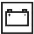
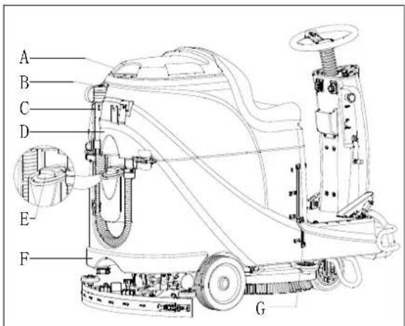
MACHINE DESCRIPTION MACHINE STRUCTURE (as shown in Figure 1)
- Steering wheel
- Seat cushion
- Recovery tank
- Recovery tank cover
- USB charging port
- Pedal
- Front wheel
- Left support bracket
- Solution Filter
- Brush
- Brush deck
- Rear wheel
- Squeegee assembly
- Solution outlet cover
- Sewage drain hose
-
Water inlet cover
-
Solution tank
- Squeegee adjustment knob
- Vacuum hose
- Squeegee knob
- Control panel
- Emergency switch
- Squeegee lifting/lowering lever
- Accelerate pedal
- Front bumper
- Solution level indicator
- Right support bracket
- Battery
- Drive motor
- Brake block bracket
- Squeegee hasp
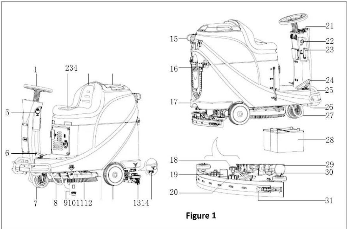
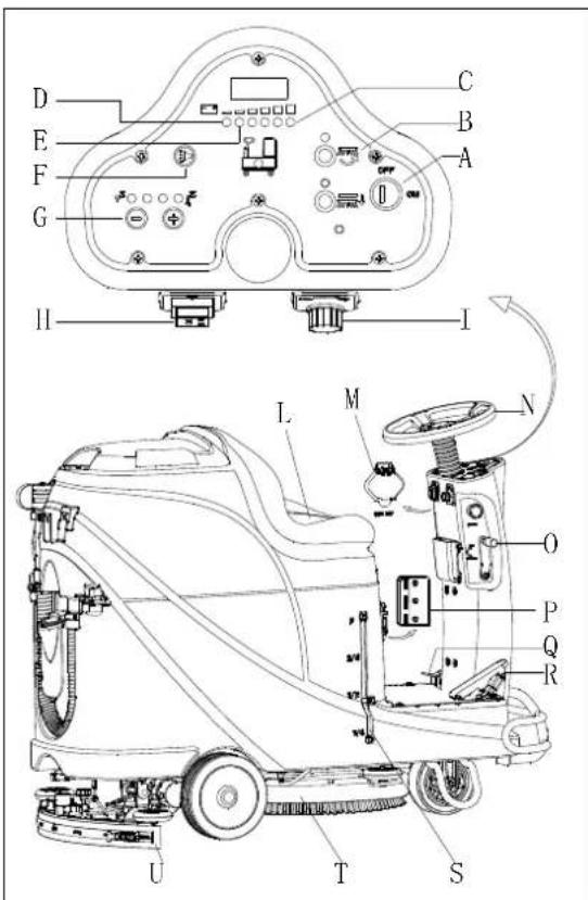
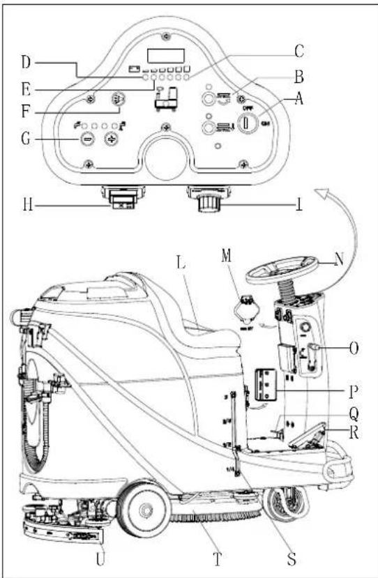
MACHINE DESCRIPTION CONTROL PANEL (as shown in Figure 2)
- LED screen
- Discharged battery warning light (Red)
- Battery semi-discharged indicator (Yellow)
- Horn button
- Solution volume adjusting button
- Forward-Backward switch
- Battery discharged indicator (Green)
- Solution tank empty indicator
- Brush button
- Key switch
-
Brush unload button
-
Drive motor trouble light
- Speed adjusting knob
- Vacuum motor overload protector
- Drive motor overload protector
- Brush motor overload protector
- Battery fully charged indicator (Green)
- Battery semi-charged indicator (Yellow)
- Battery charge indicator (Red)
- Charger plug cover
- Charger plug
LED SCREEN DISPLAY INFORMATION
STOP—Machine cannot move, brush stops working but vacuum motor can work
(00012.3) – Total working hours of machine are 12.3 hours
L0-(18) - Battery voltage lower than 18V
U-(25.5) - Battery voltage is 25.5V
ERR-01 – Squeegee is not lifted when machine turns backward
DISPLAY WINDOW OF CHARGER INDICATION LIGHT (as shown in Figure 2)
- At the beginning of charging, the red LED (49) of charger is normally on. It is the first stage of charging.
- After charging for some time, the red LED (49) on charger turns off, the yellow LED (48) turns on, this is the second stage of charging.
- When charging is completed, the yellow LED (48) turns off, the green LED (47) turns on to indicate that the battery is fully charged.

NOTE
In the process of charging, if the yellow light (48) is on, it may be caused by: Battery and charger doesn't match, battery is not connected well, or output is short-circuited.
The red light of charger flashing may be caused by the charger internal short circuit.
TECHNICAL PARAMETERS
| MODEL | AS530R | |
| Packing dimensions (Lx W x H) | mm | 1470*730*1310 |
| Machine height | mm | 1120 |
| Machine length | mm | 1360 |
| Machine width (without squeegee) | mm | 580 |
| Machine weight with empty tanks (without batteries) | Kg | 140 |
| Gross vehicle weight (GVW) | Kg | 270 |
| Shipping weight | Kg | 245 |
| Solution tank capacity | Liter | 72 |
| Recovery tank capacity | Liter | 73 |
| Vacuum motor power | Watt | 400 |
| Vacuum capacity | mm H_2O | 1223 |
| Climbing capacity (Max) | % | 10 |
| Front wheel diameter | mm | 175 |
| Rear wheel diameter | mm | 230 |
| Sound level | dB(A) | 69 |
| Solution/water Flow | L/min | 0.84-2.0 |
| Working width | mm | 530 |
| Squeegee width | mm | 730 |
| Brush/pad diameter | mm | 530 |
| Brush motor power | Watt | 450 |
| Brush speed | Rpm | 160 |
| Brush/pad pressure (Max) | Kg | 23 |
| Drive motor power | Watt | 300W |
| Working speed | Km/h | 5.5km/h |
| Voltage | V | 24V |
| Battery (optional) | Ah | 2x100AH (20 hours) |
| Battery charger (optional) | V/A | 24V 10A |
| Battery compartment size (L x W x H) | mm | 350*380*300 |
| USB charger specification | V/A | 5V, 0.8A |
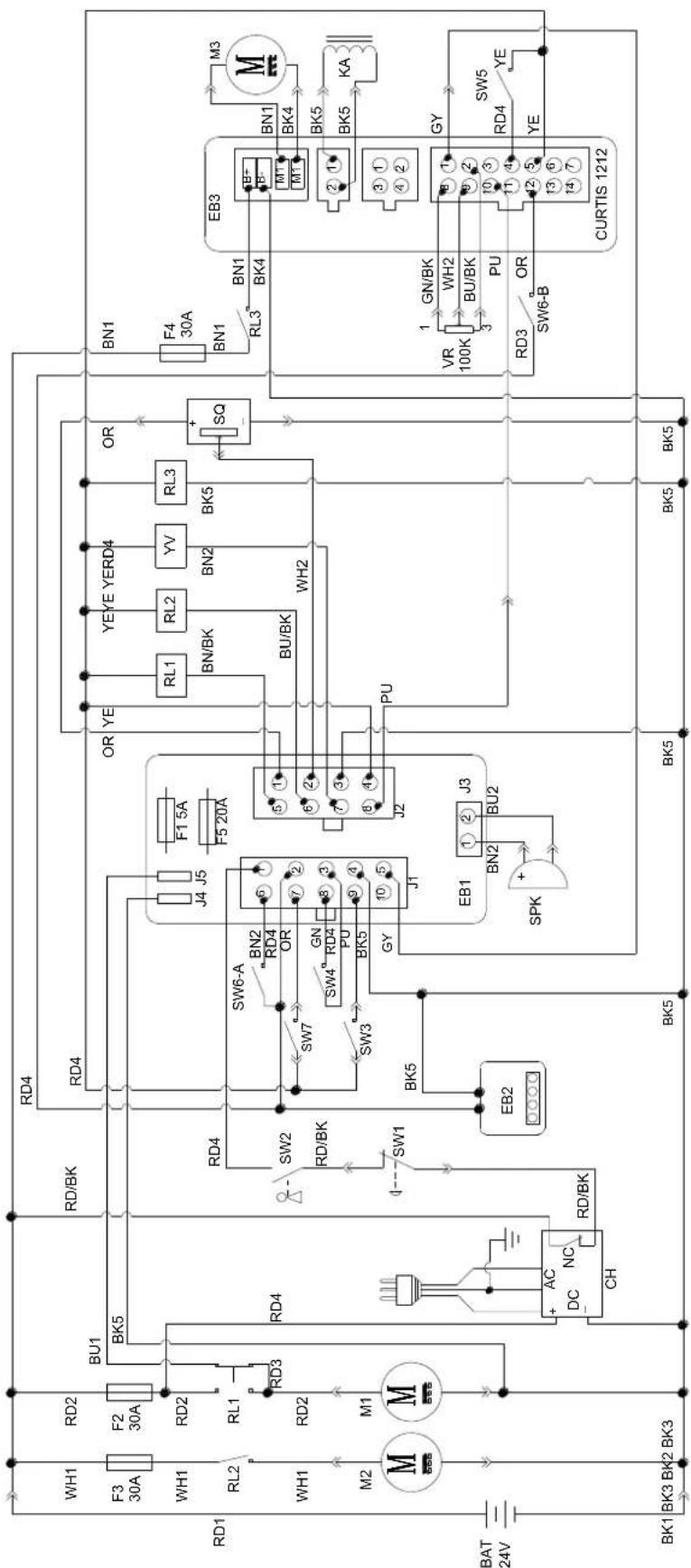
CIRCUIT DIAGRAM
| WIRE ROD | WIRE ROD | ||
| RD1 | RED/6AWG | BN/BK | BROWN/BLACK / 20AWG |
| RD2 | RED/10AWG | BU1 BLUE/18AWG | |
| RD3 | RED/18AWG | BU2 | BLUE/20AWG |
| RD4 | RED/20AWG | BU/BK | BLUE/BLACK / 20AWG |
| RD/BK | RED/BLACK / 20AWG | GN GREEN/20AWG | |
| BK1 | BLACK/6AWG | GN/BK | GREEN/BLACK /20AWG |
| BK2 | BLACK/10AWG | GY | GRAY/20AWG |
| BK3 | BLACK/12AWG | PU | PURPLE/20AWG |
| BK4 | BLACK/14AWG | OR ORANGE/20AWG | |
| BK5 | BLACK/18AWG | YE | YELLOW/20AWG |
| BN1 | BROWN/14AWG | WH1 | WHITE/12AWG |
| BN2 | BROWN/20AWG | WH2 | WHITE/20AWG |
| COMPONENTS | COMPONENTS | ||
| BAT | 24V BATTERIES | M1 | BRUSH MOTOR |
| CH | BATTERY CHARGER | M2 | VACUUM MOTOR |
| EB1 | CONTROL PANEL BOARD | M3 | DRIVE MOTOR |
| EB2 USB | CHARGING ELECTRONIC BOARD | SW1 | EMERGENCY-STOP SWITCH |
| EB3 | DRIVE ELECTRONIC BOARD | SW2 | KEY SWITCH |
| RL1 | BRUSH MOEOR ELECTROM SWITCH | SW3 | CLEAN WATER LEVEL SWITCH |
| RL2 | VACUUM MOEOR ELECTROM SWITCH | SW4 | VACUUM MOTOR SWITCH |
| RL3 | DRIVE SYSTEM ELECTROM SWITCH | SW5 | OPTIONAL MODE SWITCH |
| YV WATER ELECTROVALVE | OPTIONAL REVERSE SWITCH SW6-A | ||
| F1 | CONTROL PANEL BOARD FUSE | OPTIONAL REVERSE SWITCH SW6-B | |
| F2 | BRUSH MOTOR CIRCUIT BREAKER | SW7 | SEAT SWITCH |
| F3 | VACUUM MOTOR CIRCUIT BREAKER | SQ | FOOT THROTTLE |
| DRIVE SYSTEM CIRCUIT BREAKER F4 | SPK 12 | VDC BUZZER | |
| F5 | BRUSH RELEASE FUSE | VR SPEED POTENTIOMETER | |
| KA BRAKE | |||
| COMPONENTS | COMPONENTS | ||
| BAT | 24V BATTERIES | M1 | BRUSH MOTOR |
| CH | BATTERY CHARGER | M2 | VACUUM MOTOR |
| EB1 | CONTROL PANEL BOARD | M3 | DRIVE MOTOR |
| EB2 | USB CHARGING ELECTRONIC BOARD | SW1 | EMERGENCY-STOP SWITCH |
| EB3 | DRIVE ELECTRONIC BOARD | SW2 | KEY SWITCH |
| RL1 | BRUSH MOEOR ELECTROM SWITCH | SW3 | CLEAN WATER LEVEL SWITCH |
| RL2 | VACUUM MOEOR ELECTROM SWITCH | SW4 | VACUUM MOTOR SWITCH |
| RL3 | DRIVE SYSTEM ELECTROM SWITCH | SW5 | OPTIONAL MODE SWITCH |
| YV | WATER ELECTROVALVE | SW6-A | OPTIONAL REVERSE SWITCH |
| F1 | CONTROL PANEL BOARD FUSE | SW6-B | OPTIONAL REVERSE SWITCH |
| F2 | BRUSH MOTOR CIRCUIT BREAKER | SW7 | SEAT SWITCH |
| F3 | VACUUM MOTOR CIRCUIT BREAKER | SQ | FOOT THROTTLE |
| F4 | DRIVE SYSTEM CIRCUIT BREAKER | SPK | 12VDC BUZZER |
| F5 | BRUSH RELEASE FUSE | VR | SPEED POTENTIOMETER |
| KA | BRAKE | ||
| WIRE ROD | WIRE ROD | ||
| RD1 | RED/6AWG | BN/BK | BROWN/BLACK / 20AWG |
| RD2 | RED/10AWG | BU1 | BLUE/18AWG |
| RD3 | RED/18AWG | BU2 | BLUE/20AWG |
| RD4 | RED/20AWG | BU/BK | BLUE/BLACK/20 AWG |
| RD/BK | RED/BLACK/20AWG | GN | GREEN/20AWG |
| BK1 | BLACK/6AWG | GN/BK | GREEN/BLACK / 20AWG |
| BK2 | BLACK/10AWG | GY | GRAY/20AWG |
| BK3 | BLACK/12AWG | PU | PURPLE/20AWG |
| BK4 | BLACK/14AWG | OR | ORANGE/20AWG |
| BK5 | BLACK/18AWG | YE | YELLOW/20AWG |
| BN1 | BROWN/14AWG | WH1 | WHITE/12 AWG |
| BN2 | BROWN/20AWG | WH2 | WHITE/20AWG |
OPERATING GUIDE

WARNING!
Pay high attention to these symbols in this manual:
- DANGER!
- WARING!
- CAUTION!
- CONSULTATION
Never cover these symbols on the machine for any reason, replace it immediately if any damage.
INSTALLING AND SETTING OF NEW MACHINE BATTERY

WARNING!
The electric components of the machine can be seriously damaged if the batteries are either improperly installed or connected.
The batteries must be installed by qualified personnel. Set the battery charger (optional) and machine PCBA according to the battery type (WET or GEL/AGM).
Check the batteries whether it is damaged before installation.
Disconnect the battery connector and the battery charger plug.
Handle the batteries with great care.

NOTE
The machine requires two 12V batteries, connecting according to Figure 3.
The machine can be operated in one of following battery modes: A) WET or GEL/AGM batteries are already installed and ready to be used
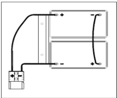
natural_image
Pure electrical circuit lines without any symbolsFigure 3
- Check the batteries and connect the battery connector to the machine.
- Insert the key switch (40) and turn to "on". If the green light (37) turns on, batteries are full charged for use; If the yellow or red light (33 or 32) turns on, the batteries must be charged.
B) Without Batteries
- If your machine isn't equipped with batteries, buy appropriate batteries [See the Technical Data Paragraph]. For battery choice and installation, turn to qualified battery Retailers.
- When batteries are ready, set the machine and the battery charger according to the type of installed batteries, then follow the procedures shown in the next paragraph.
BATTERY INSTALLATION AND BATTERY TYPE SETTING (WET OR GEL/ AGM)
Set the electronic circuit board of the machine and battery charger according to battery types (WET or GEL/AGM) following steps below:

NOTE
When install new batteries, follow Figure 4 to set DIP switch, or batteries may be damaged by wrong setting.
Machine setting
-
Insert key switch (40) and turn to "ON", pay attention to below during the first seconds of machine start:
-
If the green light (37) flash, machine is set up to use GEL/AGM batteries.
- If the yellow light (33) flash, machine is set up to use Discover EV AGM batteries.
-
If the red light (32) flash, machine is set up to use WET batteries.
-
Follow below steps to change the machine settings.
-
The factory setting of the machine is to use Discover EV AGM batteries. If the setting corresponds to selected batteries, go to step 6 directly, or follow the next step.
USER MANUAL
ENGLISH
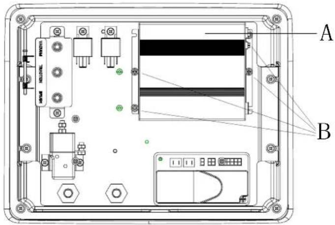
- Unscrew the screw (B, Figure 4) on control panel, then turn over the PCBA (A) on the panel to find DIP switch (D), follow Figure 4 for DIP settings.
- Perform steps in reserve order of disassembly to fix control panel and lock the screw after setting is done.
| 1 | WET BATTERIES(NOTE: Turn pin1 and pin2 of DIP switch to "OFF") | |
| 2 | DISCOVER EV AGM BATTERIES(NOTE: Turn pin 1 of DIP switch to "ON", pin2 to "OFF") | |
| 3 | GENERAL GEL/AGM BATTERIES(NOTE: Turn pin1 and pin2 of DIP switch to "ON") |
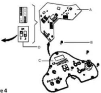
Figure 4
Battery Installation
- Open the recovery tank cover (4) and check the recovery tank (3) is empty, otherwise, empty it with the drain hose (15).
- Close the recovery tank cover (4).
- Overturn the recovery tank (3) carefully.
- The machine is supplied with cables suitable to install 2X12V batteries. Carefully put the batteries into the compartment, then install them correctly.
- Route and install the battery cable as shown in (Figure 3), then carefully tighten the nut on each battery terminal.
- Place the protection cap on each terminal, then connect the battery connector.
- Carefully lower the recovery tank (3).
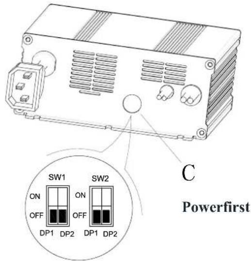
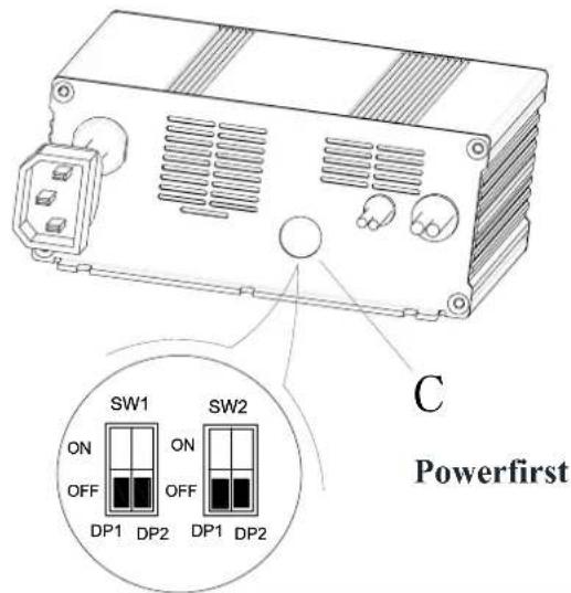
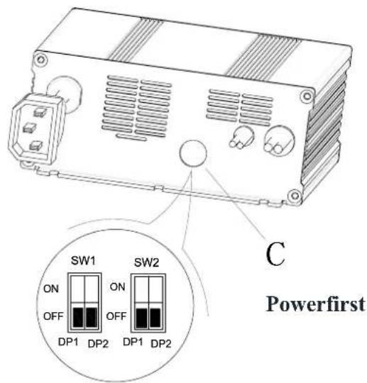
Battery Type Dip-Switches
The charger's function is controlled by 4 dip-switches (2-pair) inside the back cover. The second 2 switches should never be touched unless the charger has been replaced and their position needs to be confirmed, set the battery voltage (24V) and maximum amperage (10A) and it should always be in the Off position.
The first 2 switches are accessible through a plastic plug without opening the charger. These switches set the type of charge curve used for each type of battery. The curve type signifies the manner and magnitude in which current and voltage are applied to the battery during its distinct phases of the charge cycle.
- Remove the plastic plug covering the DIP switch access hole (C).
- Set the first 2 DIP switches (SW1) according to the table data below.
- Replace the plastic plug.
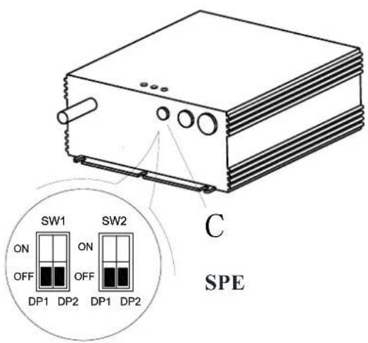
| Curve/Battery Type | SW1 | SW2 | |||
| D1 | D2 | D1 | D2 | ||
| IUla Wet | On | Off | Off | Off | |
| IUla Gel Exide | Off | Off | |||
| IUoU AGM | Off | On | |||
| IUla AGM Discover | On | On | |||

| Curve/Battery Type | SW1 | SW2 | |||
| D1 | D2 | D1 | D2 | ||
| IUIa Wet | On | Off | Off | Off | |
| IUIa Gel Exide | Off | Off | |||
| IUUa AGM | Off | On | |||
| IUIa AGM Discover | On | On | |||
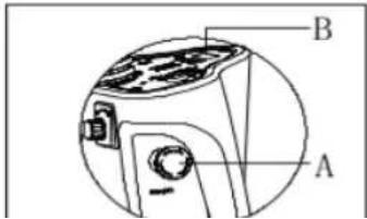
EMERGENCY BRAKING
If there is any emergency during machine operating, press the emergency switch (A, Figure 5), then all functions of machine will stop, there is no display on control panel (B, Figure 5)
BRUSH/PAD INSTALLATION AND UNINSTALLATION

NOTE
Install suitable brush (A, Figure 6) or Pad (B and C, Figure 6) according to the type of floor to be cleaned.

CAUTION
Before installation or uninstallation of brush or pad, make sure all the switches on machine are in off position and lifting up the squeegee from the floor. The operator must be equipped with suitable personnel protection devices such as gloves to reduce the risk of accidents. Proceed as following:
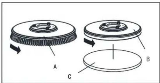
Figure 6
- Insert key switch (40) and turn to "ON".
- Press the pedal (6) forward by foot to lift brush assembly (11) from the floor.
- Rotate speed adjusting knob (42) in counterclockwise until to the end.
- Place the brush (A, Figure 5) or pad (B, Figure 5) center align with brush deck.
- Press the pedal (6) backward by foot to lower down brush assembly (11). Sit on the seat, press the brush button (39) and depress the pedal (23) slightly, the brush/pad can be assembled automatically. Repeat these steps until brush/pad is installed.
- If step5 install the brush/pad but not successfully, please manually take the brush/pad down.
- Depress the pedal (6) forward by foot to lift the brush assembly (11) from floor, press brush remove button (41) to uninstall it automatically.

CAUTION!
Rotate the speed adjusting knob (42) to the minimum speed before depressing accelerate pedal (6) to avoid the machine running too quickly when it is started. Make sure the brush/pad is installed correctly before machine operating.
-
Install the squeegee (13) and fasten the squeegee knob (20), then connect the vacuum hose (19) to the squeegee.
-
Adjust the squeegee by squeegee adjusting handle (A, Figure 7).
a) If there is gap between the ground and middle section of rear squeegee blade (B), adjust the knob (A) in counterclockwise direction (F) until all section of rear squeegee blade good contact with ground, the front blade touch the ground slightly.
b) If there is gap between the ground and both end section of rear blade(C and D), adjust the knob (A) in clockwise direction (E) until all section of rear blade good contact with the ground, the front blade touch the ground slightly.
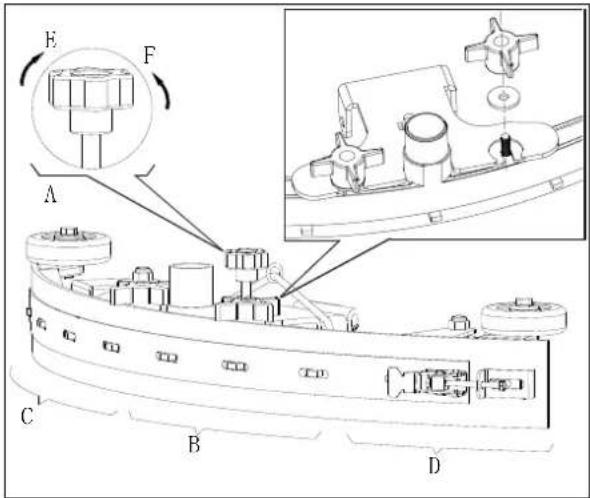
Figure 7
SOLUTION TANK FILLING
- Open the water inlet cover (E, Figure 8).
- Filling water or solution suitable for work performance through the water inlet with filter. The solution temperature must not exceed +104F (+40°C).
- Don't overfill the tank, refer to water level indicator (G) for the water volume.

WARNING!
Use only low-foam and non-flammable detergents intended for automatic scrubber applications.
Drive motor inspection
- Turn the key switch (A, Figure 9) to "ON"
- Depress the accelerate pedal (C) slightly then loosen it to check if the machine can be steered forward and stopped.
- To ensure the security, confirm if the machine can be stopped immediately by pressing the emergency button (B). Rotate the emergency button to reset it.

CAUTION
Climbing capacity of the machine must not exceed 10%.

CAUTION
The brake of drive motor is unstuck when the motor works normally, it locks when the motor stops working.
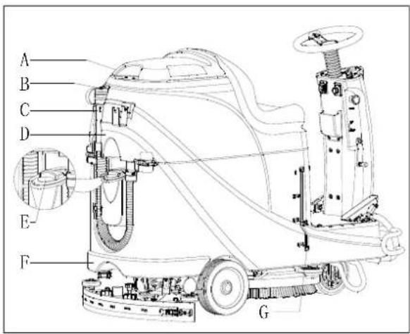
Figure 8
- Brake unstuck -the brake handle(D, Figure 9) locates above
- Brake locked – the brake handle locates lower
In some special cases, such as machine packing/unpacking, machine fault etc., need to move the machine without drive motor working, please manually set the brake to unstuck status to move it.
To avoid any security risk, ensure to set the brake back to locked status after machine movement.
MACHINE START AND STOP
Starting the machine
- Prepare the machine as shown in previous paragraph.
-
Sit on the seat (L, Figure 10), insert the key switch (A) and turn it to "ON". If the green light (C) is on, the batteries are fully charged for use. If the yellow light (E) or red light (D) is on, batteries must be charged before operation. [Refer to MENTAINENCE chapters for batteries charging]
-
Lower the squeegee assembly to the floor.

NOTE
Make sure the squeegee assembly is lifted before the machine steer backward, or the Machine will be stopped and LED screen show "Error" information.
- Lower the brush assembly to the floor.

NOTE
Make sure to turn off brush button before brush assembly is lifted, and lift the brush assembly before machine steers forward/backward.
- Press brush button (B)
- Depress the accelerate pedal (R), operate the machine forward or backward by steering wheel (N) together with forward-backward switch (H), you can adjust speed by speed adjusting knob (I).
- Adjust solution flow by solution adjusting button (G) base on cleaning requirement.
- You can charge your phone or pad through USB charging port (M) when the key switch (A) is turned to "ON".
- Press the horn button (F) to warn people when necessary.
- If necessary, press the emergency button for machine emergency stop.

NOTE
The brush motor, vacuum motor, drive motor and control circuit are protected by overload protector (P). When the overload protector trip, do not reset it immediately without finding out the root cause, and make sure the motor is cooling-off before reset.
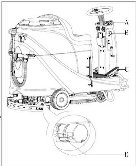
Figure 9
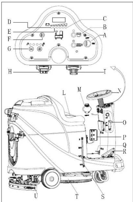
Figure 10
Stopping the machine
- Loosen the accelerate pedal (R, Figure 10), the machine stops running.
- Press brush button (B) to stop brush motor.
- Lift brush assembly (T) by depressing the pedal (Q).
-
Lift squeegee assembly (U) by squeegee lifting/lowering lever (O), and a few seconds later the vacuum system will be closed.
-
Turn the key switch to "OFF"
- Ensure the machine is stopped.
MACHINE OPERATION (SCRUBBING AND DRYING)
- Start the machine according to procedures in previous paragraphs.
- Start cleaning by following procedures in section of "Starting the machine".
- If necessary, stop the machine to adjust squeegee according to section "Adjusting the balance of squeegee".

CAUTION!
To avoid any damage to the floor surface, turn off the brush/pad-holder when the machine stop in one place.

NOTE
For correct scrubbing/drying of floors at the sides of walls, we suggest to go near the walls with right side (Bumper wheel side) of the machine as shown in below Figure 11.
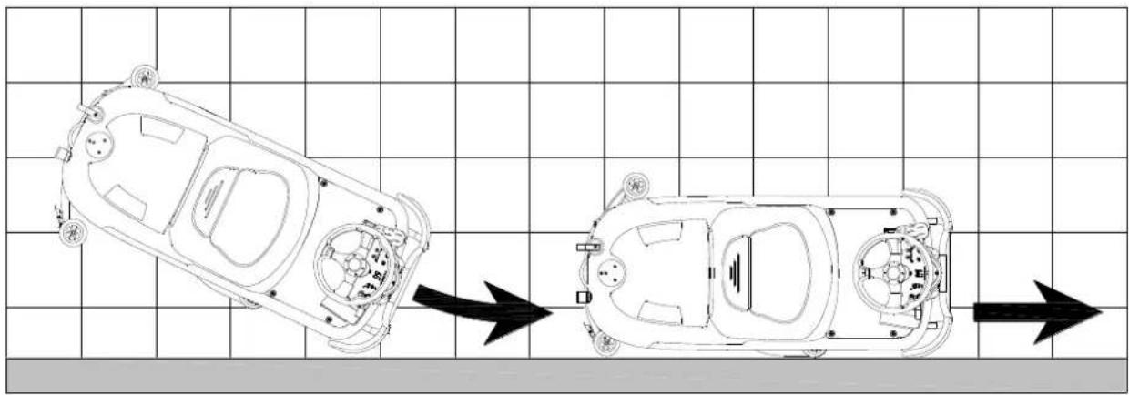
natural_image
Top-down schematic of a car showing front and side views with no text or symbolsFigure 11
Battery charging during the work
When there is green light (A, Figure 12) on, the batteries have enough power for the machine to work normally; when all the green lights off, the yellow light (C, Figure 12) is on, the power of batteries are too low, please charge the batteries; when the red light (B, Figure 12) flashes, the batteries has run out, the vacuum motor and brush motor will be turned off automatically a few seconds delay, please drive the machine for batteries charging immediately.

CAUTION!
To avoid damaging the batteries and shortening their working life, do not use the machine once the batteries are flat.
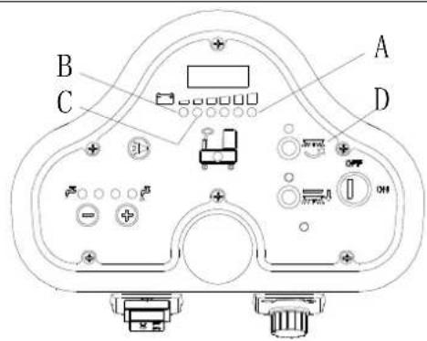
Figure 12
TANK EMPTYING
An automatic float shut-off system (B, Figure 13) blocks the vacuum system when the recovery water tank (C) is full. The vacuum system deactivation is signaled by a sudden increase in the vacuum system motor noise frequency, also the floor has not dried.

CAUTION!
If the vacuum system turns off accidentally, (For example, when the float is activated because of a sudden machine movement), to resume the operation: turnoff the vacuum system by pressing the switch (D, Figure 12), then open the cover (A, Figure 11) and check that the float inside the grid (B) has gone down to the water level. Then close the cover (A) and turn on the vacuum system by pressing the switch (D, Figure 12).
When the recovery water tank (C, Figure 13) is full, empty it according to the following procedure.
Recovery water tank emptying
- Stop the machine.
- Lift the brush/pad deck (H, Figure 12) by pressing the pedal (G).
- Lift the squeegee with the lever (H).
- Drive the machine to the appointed disposal area.
- Empty the recovery tank with the drain hose (D). Then rinse the tank with clean water.

CAUTION!
When draining the wastewater, the drain hose must be folded (A, Figure 14) and put to a low position (B, Figure 14) before opening the drain hose cover. Do not make the outlet of the drain hose upward to drain the water vertically in order to avoid wastewater spilling onto the operator.
Solution/clean water tank emptying
- Perform steps 1 to 4 in chapter "Recovery water tank emptying".
- Empty the solution tank through the outlet cover (A, Figure 15). And then, rinse the tank with clean water.
AFTER USING THE MACHINE
After working, before leaving the machine:
- Remove the brushes/pad-holder.
- Empty the tanks (B and C, Figure 15) as shown in previous paragraph.
- Perform the daily maintenance procedures (see the Maintenance chapter).
- Store the machine in a clean and dry place, with the brushes / pad-holders and the squeegee lifted or removed.
MACHINE LONG INACTIVITY
If the machine is not going to be used for more than 30 days, proceed as follows:
- Perform the procedures shown in "AFTER USING THE MACHINE" paragraph.
- Disconnect the battery connector (D, Figure 15).
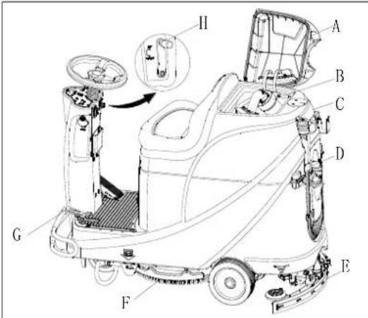
Figure 13

Figure 14

Figure 15
USING FOR THE FIRST TIME
After nine hours using of the machine for the first time, please check if any damage or abnormal situation, check whether the fasteners or fittings is loose.
MAINTENANCE

WARNING!
Maintenance procedures must be performed after the machine is turned off and the battery charger cable is disconnected. In addition, carefully read the safety chapters in the manual.
All scheduled or extraordinary maintenance procedures must be performed by qualified personnel or an authorized Service Center. This guide only describes the general and common maintenance procedures.
For other maintenance procedures that are in below maintenance schedule table, please refer to the Service Manual that can be consulted at any Service Center.
SCHEDULED MAINTENANCE TABLE
CAUTION!
The procedure marked with (1) must be performed when the machine is used after 9 hours for the first time.
The procedure marked with (2) must be done by Service Center that qualified by our company.
| Procedure | Daily, after each use | Weekly | semiannually | Yearly |
| Battery charging | ||||
| Squeegee cleaning | ||||
| Brush/Pad-holder cleaning | ||||
| Tank cleaning | ||||
| Tank sealing strip inspection | ||||
| Float ball filter cleaning | ||||
| Squeegee blade check and replacement | ||||
| Cleaning water filter cleaning | ||||
| Suction filter cleaning | ||||
| WET battery fluid level check | ||||
| Screw and nut tightness inspection | (1) | |||
| Brush/Pad-holder carbon brush check or replacement | (2) | |||
| Suction motor carbon brush check or replacement | (2) | |||
| Drive system motor carbon brush check or replacement (only for machine with traction) | (2) | |||
| Add lubricating oil for rotating parts | (1) |
BATTERY CHARGING

NOTE
Please charge the batteries when the yellow LED (32) or red LED (33) is on, or at the end of each working cycle.

CAUTION
Always keep the battery in a full charged state can extend its lifetime.

CAUTION
Please charge the battery as soon as possible if the battery level is low. Otherwise, the lifespan of battery can be reduced. It is better to check the battery at least once a week.

CAUTION!
To be especial careful when battery is charging, because there may be leaked acid in the process of charging.
Battery acid is corrosive, if it accidentally comes into contact with the skin or eyes, rinse immediately with plenty of clean water and go to see a doctor.
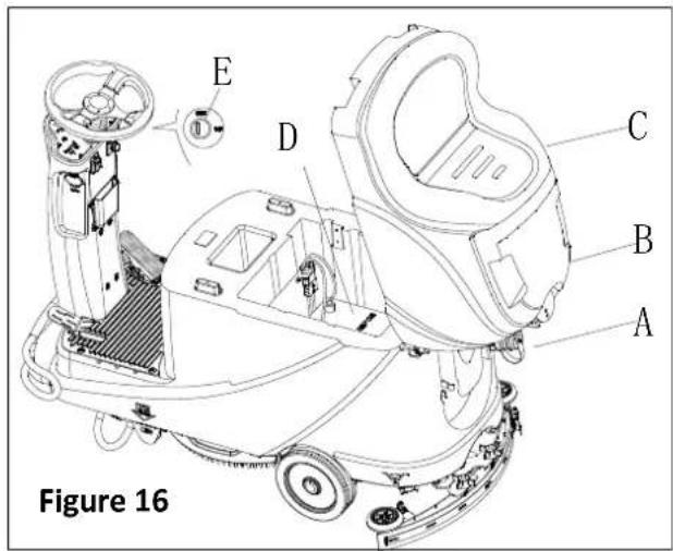
The preparation steps to charge the batteries
- Open the recovery tank cover (B, Figure 16) to check if the recovery tank (C) is empty, or empty the recovery tank through the drain hose (A).
- Drive the machine to designated charging area.
- Turn the key switch to "OFF".
-
This step only for WET batteries:
-
Clean the battery surface if necessary.
- Check the battery electrolyte level of the batteries (D), if necessary, open the cover to full fill electrolyte, and then recover it.
-
Keep the cover opened during charging.
-
Select one of below charging mode base on the selected charger type.
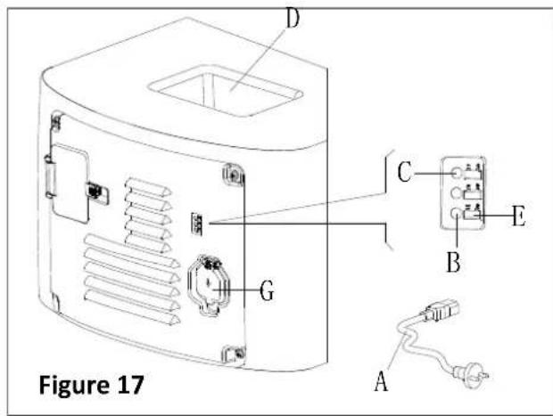
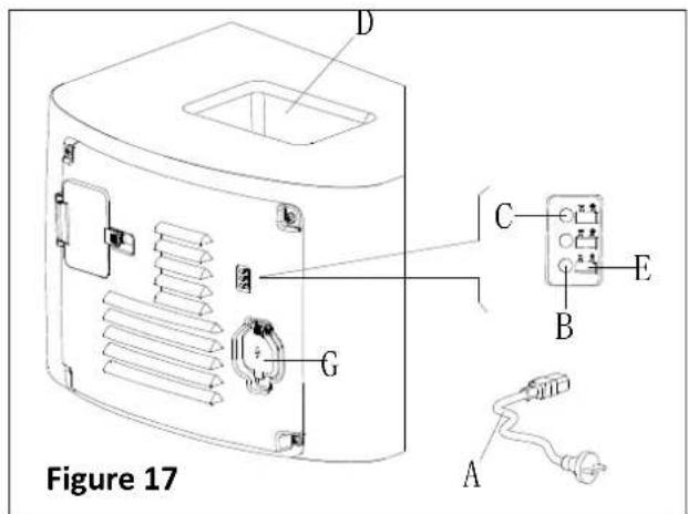
Use on-board charger for battery charging
- Connect the battery charger cable (A, Figure 17) to the electric mains (G), and then all machine functions except charging are cut off automatically.
The normally on red LED (B) states that the machine is in process of charging.
- The batteries are fully charged when the green LED (C) becomes on.
- Disconnect battery charge cable from electric mains after charging is completed, and then store the battery charger cable in the storage box (D).

NOTE
For further information about on-board charger (E, Figure 17), please refer to relevant manual from service center.
BRUSH/PAD CLEANING

CAUTION!
It is recommended to wear gloves when cleaning the brush/pad-holder, since it may contain sharp fragments.
- Take the brush/pad-holder off base on procedures in previous sections.
- Clean the brush/pad-holder using water and detergent.
- Check the integrity and abrasion conditions of the bristle on the brush, if necessary, replace the brush.
- Check the abrasion condition of the polishing pad, if necessary, replace it.
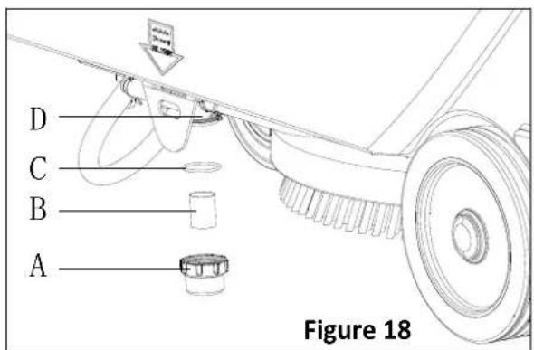
SOLUTION FILTER CLEANING
- Drive the machine to the flat ground.
- Make sure the machine is off.
- Empty the solution tank (optional step).
- Take down the solution filter cover (A, Figure 18) to clean the filter screen (B), and them fix them back to the filter support (D).

NOTE
The filter screen (B) must be correctly positioned to the housing of filter support (D).
SQUEEGEE CLEANING

NOTE
The squeegee must be clean and its blades must be in good conditions in order to get good drying.

CAUTION
It is advisable to wear protective gloves when cleaning the squeegee because there may be sharp debris.
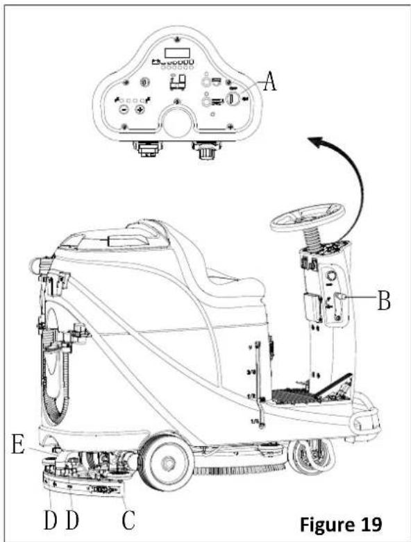
- Drive the machine on a level floor.
- Turn the key switch (A, Figure 19) to "OFF".
- Lower the squeegee (B) with the lever (C).
- Loosen the knobs (D) and remove the squeegee.
- Disconnect the vacuum hose (E) from the squeegee.
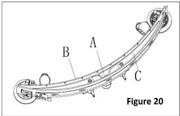
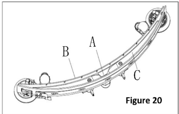
- Clean the steel or aluminum squeegee, especially the compartments (A, Figure 20) and the holes (B). Check the integrity, cuts and tears of the front blade (B) and rear blade (C), if necessary, replace them according to procedures in the following paragraph.
- Assemble the squeegee in the reverse order of disassembly.
SQUEEGEE BLADE CHECK AND REPLACEMENT
- Clean the steel or the aluminum squeegee, as shown in the previous paragraph.
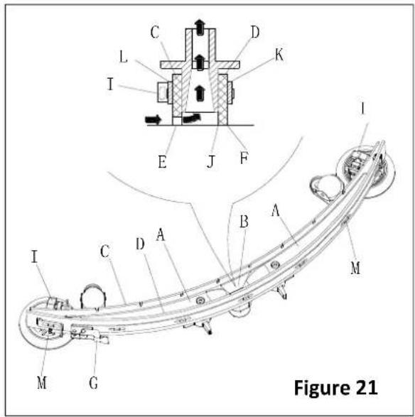
- Check that the edges (E, Figure 21) of the front blade (C) and the edges (F) of the rear blade (D) lay down on the same level, along their length; if necessary adjust their height according to the following procedure:
- Remove the tie rod (G), disengage the fasteners (M) and adjust the rear blade (D), then engage the fasteners (M) and install the tie rod (G).
- Loosen the knobs (I) and adjust the front blade (C), then tighten the knobs.
-
Check the front blade (C) and rear blade (D) for wear, cuts and tears; if necessary replace them according to the following procedure. Check that the front corner (J) of the rear blade (D) is not worn; if necessary overturn the blade to replace the worn corner with an integral one. If the other corners are worn too, replace the blade according to the following procedure:
-
Remove the tie rod (G), disengage the fastener (M) and remove the retaining strip (K), then replace/overturn the rear blade (D). Assemble the blade in the reverse order of disassembly.
- Unscrew the knobs (I) and remove the retaining strip (L), then replace front blade (C). Assemble the blade in the reserve order of disassembly. After the blade replacement (or overturning), adjust the height as shown in the previous step.
- Connect the vacuum hose (A, Figure 22) to the squeegee.
- Install the squeegee (B) and screw down the knobs (C).
- If necessary, adjust the squeegee balance adjusting knob (D).
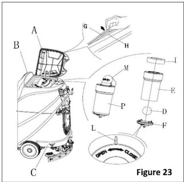
TANK AND VACUUM GRID WITH FLOAT CLEANING, AND COVER GASKET CHECK
- Drive the machine on a level floor.
- Ensure that the machine is off and the ignition key (40) has been removed.
- Turn the recovery tank lid (A, Figure 23) 90 degree position where it can be took off from the tank, and then take down the float ball filter (P) from the tank.
- Clean the recovery tank lid (A), recovery tank (B), clean water tank (C) and the float ball filter support frame (E). Empty the recovery tank with the drain hose (15).
- If necessary, follow the symbols "OPEN" and "CLOSE" as shown in Figure 23 to open the bottom cover (F) of float ball filter and then clean the float ball (D), filter support frame (E) and filter sponge (I). After cleaning, fix the float ball (D) into the filter support frame (E) and then align the mark groove (L) of the bottom cap (F) of the float ball filter with the mark groove (L) of the float filter support frame (E). Screw the bottom cap of the float ball filter tight, and fix the filter sponge (I) onto the float filter support frame (E). Finally, connect it to the sewage suction hose (M).
- Inspect the integrity of the tank sealing strip.

NOTE
Tank sealing strip (G) makes to produce the vacuum inside the tank when suction motor works. The tank must be sealed can effectively absorb the water from the ground to recovery tank.
- Check whether the contact surface of sealing strip (G) is integrity and sealing is sufficient. If necessary, take the sealing strip of the tank out of the groove (H) and replace it. Assembly the new sealing strip as shown in Figure 23, the joint should be back in the middle area.
- Close the recovery tank lid (A).

Figure 22
FUSE CHECK/REPLACEMENT
- Turn the key switch (D, Figure 24) to "OFF".
- Disconnect the battery connect cable.
- Unscrew the screws (C) on the control panel and then turn over the PCBA to find the fuse (A and B).
- Check/replace the fuses:
A) F1 is the low-power circuit fuse (5A)
B) F3 is brush dismount fuse (20A) - After check/replacement is done, re-assemble in the reserve order of dismount.
- Check or reset the motor overload protector.
E) F5 is vacuum motor overload protector (30A)
F) F4 is drive motor overload protector (30A)
G) F2 is brush motor overload protector (30A)
ACCESSORIES/OPTIONS
In addition to the standard components, the machine can be equipped with the following accessories/options, according to the machine specific use.
For further information concerning the above mentioned optional accessories, contact an authorized retailer.
Accessories/Options
See "Parts List" section
- GEL/AGM batteries
- Pads of different materials
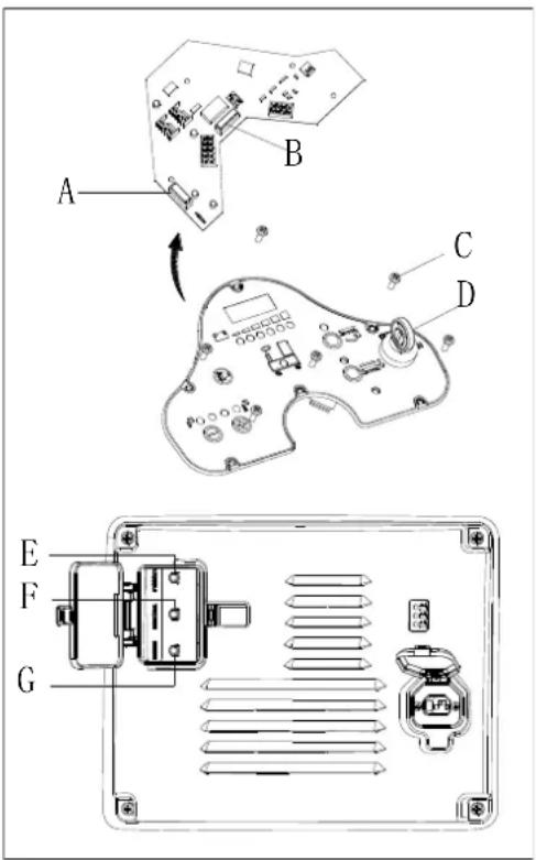
Figure 24
TROUBLE SHOOTING
| Trouble | Probable causes | Remedy |
| The motors do not work; no warning light turns on (C9) | The battery connector is disconnected | Connect the battery connector |
| The batteries are completely discharged | Charge the batteries | |
| The machine do not work, red battery capacity warning light turns on (C8) | The batteries level is too low | Charge the batteries |
| The machine do not go-forward / backward | The control circuit board fault | Replace the control circuit board |
| The drive motor controller fault | Refer to “DRIVE MOTOR ERROR INDICATOR INFORMATION” | |
| The operator not on the seat | Sit on the seat | |
| Squeegee is not lifted during machine goes backward | Lift the squeegee | |
| The brush motor does not work | The control circuit board fault | Replace the control circuit board |
| Brush motor overload | Use soft bristle brush that is suitable for cleaning, and reset the brush motor overload protector | |
| Brush motor contactor fault | Contact after-sales service | |
| Brush motor carbon brush wearing | Contact after-sales service | |
| Obstacles prevent the brush rotating | Clean the brush | |
| The drive motor does not work | Drive motor trouble light turns on | Refer to “DRIVE MOTOR ERROR INDICATOR INFORMATION” |
| Drive motor overload | Reset drive motor overload protector and check drive motor/circuit | |
| The vacuum motor does not work | Vacuum motor overload | Reset vacuum motor overload protector and check vacuum motor |
| Relay of vacuum motor fault | Contact after-sales service | |
| Control board fault | Replace the control board | |
| Insufficient suction, the floor cannot be dried | Recovery tank is full | Empty the recovery tank |
| Drain hose and squeegee poor connection | Connect the drain hose and squeegee correctly | |
| Float ball filter block | Clean the float ball filter and check the float ball position status | |
| Squeegee is dirty or wearing | Check and clean the squeegee | |
| The recovery tank cover is not closed properly, or the gasket is damaged, or the Bend tube is clogged | Close the cover correctly, or replace the gasket or clean the Bend tube. | |
| The Recovery tank is dirty | Clean the recovery tank | |
| Insufficient solution supply to brush plate | The solution filter is dirty | Clean the filter |
| The solution tank empty indicator is on | Fill the solution tank | |
| The solution tank is too dirty | Clean the solution tank | |
| Squeegee leaves scratch on the floor | There are debris under the squeegee blade | Remove the debris |
| Squeegee blade wear, crack, aged | Replace the squeegee blades | |
| The squeegee balance is not adjusted | Adjust the squeegee balance | |
| Drive motor brake failure | The brake is locked | Set the brake unstuck |
DRIVE MOTOR ERROR INDICATOR INFORMATION
= Must cycle keys witch to clear.
| LED CODES | FAULT | POSSIBLE CAUSE | |
| 1.1 | ☐☐ | THERMAL FAULT | 1. Temperature >80°C or < -10°C.2. Excessive load on vehicle.3. Operation in extreme environments.4. Electromagnetic brake not releasing. |
| 1.2 | ☐☐☐ | THROTTLE FAULT | 1. Throttle input wire open or shorted.2. Throttle pot defective.3. Wrong throttle type selected. |
| 1.3 | ☐☐☐☐ | SPEED POT FAULT | 1. Speed limit pot wire(s) broken or shorted.2. Broken speed limit pot. |
| 1.4 | ☐☐☐☐☐ | UNDERVOLTAGE FAULT | 1. Battery voltage <17 volts.2. Bad connection at battery or controller. |
| 1.5 | ☐☐☐☐☐☐ | OVERVOLTAGE FAULT | 1. Battery voltage >31 volts.2. Vehicle operating with charger attached.3. Intermittent battery connection. |
| 2.1 | ☐☐☐ | MAIN OFF FAULT | 1. Main contactor driver failed open. |
| 2.3 | ☐☐☐☐☐ | MAIN FAULT * | 1. Main contactor welded or stuck open.2. Main contactor driver fault. |
| 2.4 | ☐☐☐☐☐☐ | MAIN ON FAULT | 1. Main contactor driver failed closed. |
| 3.1 | ☐☐☐☐ | WIRING FAULT * | 1. Misadjusted throttle.2. Broken throttle pot or throttle mechanism. |
| 3.2 | ☐☐☐☐☐ | BRAKE ON FAULT | 1. Electromagnetic brake driver shorted.2. Electromagnetic brake coil open. |
| 3.3 | ☐☐☐☐☐☐ | PRECHARGE FAULT * | 1. Brake driver shorted.2. Precharge circuit damaged.3. MOSFET failure. |
| 3.4 | ☐☐☐☐☐☐☐ | BRAKE OFF FAULT | 1. Electromagnetic brake driver open.2. Electromagnetic brake coil shorted. |
| 3.5 | ☐☐☐☐☐☐☐☐ | HPD FAULT | 1. Improper sequence of throttle and KSI, push, or inhibit inputs.2. Misadjusted throttle pot. |
| 4.1 | ☐☐☐☐☐ | CURRENT SENSE FAULT * | 1. Short in motor or in motor wiring.2. Controller failure. |
| 4.2 | ☐☐☐☐☐☐ | HARDWARE FAILSAFE * | 1. Motor voltage does not correspond to throttle request.2. Short in motor or in motor wiring.3. Controller failure. |
| 4.3 | EEPROM CHECKSUM FAULT † | 1. EEPROM failure or fault. | |
| 4.5 | BATTERY DISCONNECT FAULT ※ | 1. Battery not connected.2. Poor connection to battery terminals. | |
= Must use programmer to clear, as follows: select Program menu, alter data value of any parameter, cycle keys witch.

NOTE
The machine which is equipped with on-board charger will not be operated when the on-board charger malfunction, please contact our qualified maintenance center for help.
SCRAPPING
Scrap the machine by the qualified waste treatment institution.
Before the machine is scrapped, please take away and segregate below subassembly that relevant laws and regulations request must be disposed in appropriate way.
- Battery
- Brush/Pad-holder
- Plastic hose and plastic parts
- Electrical and electronic components (*)
(*) Please contact our service center to destroy any of electrical and electronic components.
TABLE DES MATIÈRES
INTRODUCTION....23
CONTENU DU MANUEL ET BUT 23
COMMENT GARDER CE MANUEL 23
DÉCLARATION DE CONFORMITÉ....23
ACCESSOIRES ET ENTRETIEN....23
CHANGEMENT ET AMÉLIORATION 23
CHAMP D'APPLICATION 23
DONNÉES D'IDENTIFICATION DE LA MACHINE....23
TRANSPORT ET DÉBALLAGE....23
SÉCURITÉ 24
SYMBOLES QUI APPARAISSENT SUR LE MANUEL D'UTILISATION....24
CONSIGNES GÉNÉRALES DE SÉCURITÉ....24
DESCRIPTION DE LA MACHINE....26
STRUCTURE DE LA MACHINE 26
PANNEAU DE COMMANDE....27
INFORMATIONS D'AFFICHAGE ÉCRAN LED 27
FENÊTRE D'AFFICHAGE DU VOYANT DU CHARGEUR....27
ACCESSOIRES/OPTIONS 42
DÉPANNAGE 42
RECYCLAGE 44
INTRODUCTION

REMARQUE
COMMENT GARDER CE MANUEL
DÉCLARATION DE CONFORMITÉ
natural_image
Pure electrical circuit lines without any symbolsFigure 3
| Curve/Battery Type | SW1 | SW2 | ||
| D1 D2 D1 | D2 | |||
| IUla Wet | On | Off | Off | Off |
| IUla Gel Exide | Off | Off | ||
| IUoU AGM | Off | On | ||
| IUla AGM Discover | On | On | ||
| Curve/Battery Type | SW1 | SW2 | |||
| D1 | D2 | D1 | D2 | ||
| IUIa Wet | On | Off | Off | Off | |
| IUIa Gel Exide | Off | Off | |||
| IUUa AGM | Off | On | |||
| IUIa AGM Discover | On | On | |||
FREINAGE D'URGENCE
Figure 7
REMLISSAGE DU RÉSERVOIR DE LA SOLUTION
Figure 8
Figure 9

REMARQUE
Figure 10
Arrêt de la machine
natural_image
Top-down line drawing of a car showing front and side views with no text or symbolsFigure 11
Figure 13
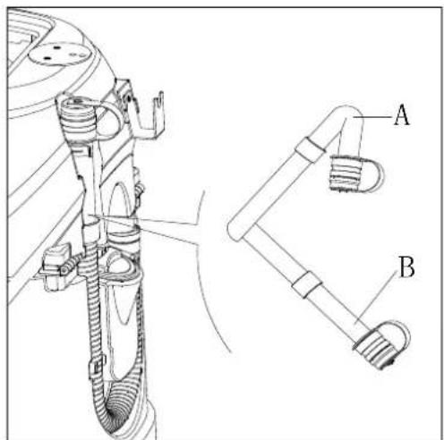
Figure 14

Figure 15
UTILISATION POUR LA PREMIÈRE FOIS
VÉRIFICATION ET REMPLACEMENT DE LA LAMELLE DE L'EMBOUCHURE

REMARQUE
VÉRIFICATION / REMPLACEMENT DU FUSIBLE
Figure 24
DÉPANNAGE
natural_image
Pure electrical circuit lines without any symbolsFigura 3
| Curve/Battery Type | SW1 | SW2 | |||
| D1 | D2 | D1 | D2 | ||
| IUla Wet | On | Off | Off | Off | |
| IUla Gel Exide | Off | Off | |||
| IUoU AGM | Off On | ||||
| IUla AGM Discover | On | On | |||
| Curve/Battery Type | SW1 | SW2 | |||
| D1 | D2 | D1 | D2 | ||
| IUIa Wet | On | Off | Off | Off | |
| IUIa Gel Exide | Off | Off | |||
| IUUa AGM | Off | On | |||
| IUIa AGM Discover | On | On | |||
FRENO DE EMERGENCIA
Figura 7
Figura 8
Figura 9

Figura 10
Parar la máquina
natural_image
Top-down schematic of two cars on a grid surface, showing front and side views with no text or symbolsFigura 11
Figura 13

Figura 14

Figura 15
PRIMER USO
Figura 24
MACHINENMODELL......
MACHINENSERIENNUMMER......
natural_image
Pure electrical circuit lines without any symbolsAbbildung 3
Abbildung 4
Batterien einsetzen
Abbildung 7
Abbildung 8
Abbildung 9

HINWEIS
Abbildung 10
natural_image
Top-down line drawing of a car showing front and side views with no text or symbolsAbbildung 11
Abbildung 13
Abbildung 14
Abbildung 15
ERSTGEBRAUCH

ANMERKUNG
Abbildung 24
FEHLERBEHEBUNG
ACCESSOIRES/OPTIES 108
PROBLEEMOPLOSSING 108
SLOOP 110
INLEIDING

OPMERKING
U-(25.5) - Accuspanning is 25.5V
flowchart
graph TD
    subgraph Power Supply
        A["Power Supply M2"] --> B["AC"]
        C["DC"] --> D["NC"]
        E["SW1"] --> F["SW3"]
        G["SW4"] --> H["SW5"]
        I["SW6-A"] --> J["OR"]
        K["SW7"] --> L["SW8"]
        M["SW9"] --> N["SW10"]
        O["SW11"] --> P["SW12"]
        Q["SW13"] --> R["SW14"]
        S["SW15"] --> T["SW16"]
        U["SW17"] --> V["SW18"]
        W["SW19"] --> X["SW20"]
        Y["SW21"] --> Z["SW22"]
        AA["SW23"] --> AB["SW24"]
        AC["SW25"] --> AD["SW26"]
        AE["SW27"] --> AF["SW28"]
        AG["SW29"] --> AH["SW30"]
        AI["SW31"] --> AJ["SW32"]
        AK["SW33"] --> AL["SW34"]
        AM["SW35"] --> AN["SW36"]
        AO["SW37"] --> AP["SW38"]
        AQ["SW39"] --> AR["SW40"]
        AS["SW41"] --> AT["SW42"]
        AU["SW43"] --> AV["SW44"]
        AW["SW45"] --> AX["SW46"]
        AY["SW47"] --> AZ["SW48"]
        BA["SW49"] --> BB["SW50"]
        BC["SW51"] --> BD["SW52"]
        BE["SW53"] --> BF["SW54"]
        BG["SW55"] --> BH["SW56"]
        BI["SW57"] --> BJ["SW58"]
        BK["SW59"] --> BL["SW60"]
        BM["M3"] --> BN1
        BN1 --> BN1A["F4 30A"]
        BN1A --> BN1B["BN1"]
        BN1B --> BN1C["RL3"]
        BN1C --> BN1D["BN1"]
        BN1D --> BN1E["BK4"]
        BN1E --> BN1F["M 100K"]
        BN1F --> BN1G["BK4"]
        BN1G --> BN1H["M 300K"]
        BN1H --> BN1I["BK5"]
        BN1I --> BN1J["KA"]
        BN1J --> BN1K["M 500K"]
        BN1K --> BN1L["BK5"]
        BN1L --> BN1M["KA"]
    end
    subgraph Power Supply
        N["Power Supply SW1"] --> O
    end
    subgraph Control Circuit
        P["Control Circuit"] --> Q
    end
    style Power Supply fill:#f9f,stroke:#333
    style Control Circuit fill:#ccf,stroke:#333
| WIRE ROD | WIRE ROD | ||
| RD1 | RED/6AWG | BN/BK | BROWN/BLACK / 20AWG |
| RD2 | RED/10AWG | BU1 BL | UE/18AWG |
| RD3 | RED/18AWG | BU2 | BLUE/20AWG |
| RD4 | RED/20AWG | BU/BK | BLUE/BLACK / 20AWG |
| RD/BK | RED/BLACK / 20AWG | GN GREEN/20AWG | |
| BK1 | BLACK/6AWG | GN/BK | GREEN/BLACK /20AWG |
| BK2 | BLACK/10AWG | GY | GRAY/20AWG |
| BK3 | BLACK/12AWG | PU | PURPLE/20AWG |
| BK4 | BLACK/14AWG | OR ORANGE/20AWG | |
| BK5 | BLACK/18AWG | YE | YELLOW/20AWG |
| BN1 | BROWN/14AWG | WH1 | WHITE/12AWG |
| BN2 | BROWN/20AWG | WH2 | WHITE/20AWG |
| COMPONENTS | COMPONENTS | ||
| BAT | 24V BATTERIES | M1 | BRUSH MOTOR |
| CH | BATTERY CHARGER | M2 | VACUUM MOTOR |
| EB1 | CONTROL PANEL BOARD | M3 | DRIVE MOTOR |
| EB2 USB | CHARGING ELECTRONIC BOARD | SW1 | EMERGENCY-STOP SWITCH |
| EB3 | DRIVE ELECTRONIC BOARD | SW2 | KEY SWITCH |
| RL1 | BRUSH MOEOR ELECTROM SWITCH | SW3 | CLEAN WATER LEVEL SWITCH |
| RL2 | VACUUM MOEOR ELECTROM SWITCH | SW4 | VACUUM MOTOR SWITCH |
| RL3 | DRIVE SYSTEM ELECTROM SWITCH | SW5 | OPTIONAL MODE SWITCH |
| YV WATER ELECTROVALVE | OPTIONAL REVERSE SWITCH SW6-A | ||
| F1 | CONTROL PANEL BOARD FUSE | OPTIONAL REVERSE SWITCH SW6-B | |
| F2 | BRUSH MOTOR CIRCUIT BREAKER | SW7 | SEAT SWITCH |
| F3 | VACUUM MOTOR CIRCUIT BREAKER | SQ | FOOT THROTTLE |
| DRIVE SYSTEM CIRCUIT BREAKER F4 | SPK 12 | VDC BUZZER | |
| F5 | BRUSH RELEASE FUSE | VR SPEED POTENTIOMETER | |
| KA BRAKE | |||
| ONDERDELEN | ONDERDELEN | ||
| BAT | 24V ACCU 'S | M1 | BORSTELMOTOR |
| CH | ACCULADER | M2 | VACUÜMMOTOR |
| EB1 | BEDIENINGSPANEEL | M3 | RIJMOTOR |
| EB2 | USB- ELEKTRONISCH OPLAADPANEEL | SW1 | NOODSTOPSCHAKELAAR |
| EB3 | STATION ELEKTRONISCH PANEEL | SW2 | SLEUTELSCHAKELAAR |
| RL1 | BORSTELMOTOR ELECTROM SCHAKELAAR | SW3 | SCHOON WATER NIVEAUSCHAKELAAR |
| RL2 | VACUÜM MOTOR ELECTROM SCHAKELAAR | SW4 | VACUÜM MOTORSCHAKELAAR |
| RL3 | STATION SYSTEEM ELECTROM SCHAKELAAR | SW5 | OPTIONELE MODUS-SCHAKELAAR |
| YV | WATER ELECTROKLEP | SW6-A | OPTIONELE ACHTERUITRIJSCHAKELAAR |
| F1 | CONTROLE PANEEL BORDZEKERING | SW6-B | OPTIONELE ACHTERUITRIJSCHAKELAAR |
| F2 | BORSTELMOTOR CIRCUITBEVEILIGING | SW7 | STOEL SCHAKELAAR |
| F3 | VACUÜMMOTOR CIRCUITVERMOGENSCHAKELAAR | SQ | VOETGASHENDEL |
| F4 | STATION SYSTEEM CIRCUITVERMOGENSCHAKELAAR | SPK | 12VDC-ZOEMER |
| F5 | BORSTEL ZEKERING VOOR DE ONTGRENDELKNOP | VR | SNELHEID POTENTIOMETER |
| KA | REM | ||
| WALSDRAAD | WALSDRAAD | ||
| RD1 | ROOD/6AWG | BN/BK | BRUIN/ZWART / 20AWG |
| RD2 | ROOD/10AWG | BU1 | BLAUW/18AWG |
| RD3 | ROOD/18AWG | BU2 | BLAUW/20AWG |
| RD4 | ROOD/20AWG | BU/BK | BLAUW/ZWART/20 AWG |
| RD/BK | ROOD/ZWART/20AWG | GN | GROEN/20AWG |
| BK1 | ZWART/6AWG | GN/BK | GROEN/ZWART /20AWG |
| BK2 | ZWART/10AWG | GY | GRIJS/20AWG |
| BK3 | ZWART/12AWG | PU | PAARS/20AWG |
| BK4 | ZWART/14AWG | OR | ORANJE/20AWG |
| BK5 | ZWART/18AWG | YE | GEEL/20AWG |
| BN1 | BRUIN/14AWG | WH1 | WIT/12 AWG |
| BN2 | BRUIN/20AWG | WH2 | WIT/20AWG |
WERKINGSGIDS

WAARSCHUWING!
- GEVAAR!
- WAARSCHUWING!
- LET OP!
- RAADPLEGEN
natural_image
Pure electrical circuit lines without any symbolsFiguur 3
Figuur 4
| Curve/Battery Type | SW1 | SW2 | |||
| D1 | D2 | D1 | D2 | ||
| IUla Wet | On | Off | Off | Off | |
| IUla Gel Exide Off Off | |||||
| IUoU AGM | Off | On | |||
| IUla AGM Discover | On | On | |||

| Curve/Battery Type | SW1 | SW2 | |||
| D1 | D2 | D1 | D2 | ||
| IUIa Wet | On | Off | Off | Off | |
| IUIa Gel Exide Off Off | |||||
| IUUa AGM | Off | On | |||
| IUIa AGM Discover | On | On | |||
NOODSITUATIE REMMEN
Figuur 7
VULLEN VAN OPLOSSINGSTANK
Figuur 9
Figuur 10
natural_image
Top-down line drawing of two cars on a grid surface, showing front and side views with no text or symbolsFiguur 11
Figuur 13
Figuur 14
Oplossing/schoonwater tank leegmaken
Figuur 15
GEBRUIK VOOR DE EERSTE KEER
CONTROLE / VERVANGING VAN DE ZEKERING
Figuur 24
PROBLEEMOPLOSSING
natural_image
Pure electrical circuit lines without any symbolsFigura 3
Figura 4
| Curve/Battery Type | SW1 | SW2 | |||
| D1 | D2 | D1 | D2 | ||
| IUla Wet | On | Off | Off | Off | |
| IUla Gel Exide | Off | Off | |||
| IUoU AGM | Off | On | |||
| IUla AGM Discover | On | On | |||
| Curve/Battery Type | SW1 | SW2 | |||
| D1 | D2 | D1 | D2 | ||
| IUIa Wet | On | Off | Off | Off | |
| IUIa Gel Exide | Off | Off | |||
| IUUa AGM | Off | On | |||
| IUIa AGM Discover | On | On | |||
FRENATA DI EMERGENZA
Figura 7
Figura 8
AVVIARE E FERMARE LA MACCHINA
Avviare la macchina
Figura 9

Figura 10
Fermare la macchina
natural_image
Top-down line drawing of two cars on a grid surface, showing front and side views with no text or symbolsFigura 11
Figura 13
Figura 14
Figura 15
PRIMO UTILIZZO DELLA MACCHINA
Figura 24
INNHOLD OG FORMÅL....133
OPPBEVARING AV HÄNDBOKEN 133
SAMSVARSERKLÆRING 133
TILBEH∅R OG VEDLIKEHOLD....133
ENDRINGER OG FORBEDRINGER 133
BRUKSOMRÅDE 133
IDENTIFIKASJONSDATA....133
TRANSPORT OG UTPAKKING....133
SIKKERHET 134
SYMBOLER SOM ER BRUKT I BRUKSANVISNINGEN 134
GENERELLE SIKKERHETSANVISNINGER 134
MASKINBESKRIVELSE 136
MASKINSTRUKTUR....136
BETJENINGSPANEL 137
INFORMASJON | LED-DISPLAYET 137
LADEINDIKATORER....137
TECHNICAL PARAMETERS 138
KOBLINGSSKJEMA....139
BRUKERVEILEDNING....141
INSTALLASJON OG INNSTILLING AV NYTT BATTERI 141
INSTALLASJON AV BATTERI OG INNSTILLING AV BATTERITYPE (VÅT ELLER GEL/AGM) 141
N∅DBREMS 143
MONTERING OG DEMONTERING AV B∅RSTE/PAD 143
JUSTERING AV VINKEL PÅ NAL....144
FYLLING AV VASKEL∅SNINGSTANK....144
START OG STOPP AV MASKINEN....145
MASKINDRIFT (SKURING OG T∅RKING)....146
T∅MMING AV TANK 147
ETTER BRUK AV MASKINEN 147
LAGRING OVER LANG TID 147
F∅RSTEGANGS BRUK 148
VEDLIKEHOLD....148
VEDLIKEHOLDSPLAN 148
BATTERILADING 148
RENGJ∅RING AV B∅RSTE/PAD 149
RENGJ∅RING AV VASKEL∅SNINGSFILTER 150
RENGJ∅RING AV NAL....150
SJEKK OG SKIFT AV NAL 150
RENGJ∅RING AV TANK OG SUGEFILTER MED FLOTT∅R OG SJEKK AV TETNING PÅ DEKSELET 151
SJEKKE/SKIFTE SIKRINGER....152
TILBEH∅R/EKSTRAUTSTYR 152
FEILS∅ KING....152
DESTRUERING 154
INNLEDNING

MERK
TILBEH∅R OG VEDLIKEHOLD
TRANSPORT OG UTPAKKING
flowchart
graph TD
    subgraph Power Supply
        A["Power Supply M2"] --> B["AC"]
        C["DC"] --> D["NC"]
        E["SW1"] --> F["SW3"]
        G["SW4"] --> H["SW5"]
        I["BU"] --> J["BU2"]
        K["SW6-A"] --> L["OR"]
        M["SW7"] --> N["SW8"]
        O["SW9"] --> P["SW10"]
        Q["SW11"] --> R["SW12"]
        S["SW13"] --> T["SW14"]
        U["SW15"] --> V["SW16"]
        W["SW17"] --> X["SW18"]
        Y["SW19"] --> Z["SW20"]
        AA["SW21"] --> AB["SW22"]
        AC["SW23"] --> AD["SW24"]
        AE["SW25"] --> AF["SW26"]
        AG["SW27"] --> AH["SW28"]
        AI["SW29"] --> AJ["SW30"]
        AK["SW31"] --> AL["SW32"]
        AM["SW33"] --> AN["SW34"]
        AO["SW35"] --> AP["SW36"]
        AQ["SW37"] --> AR["SW37"]
        AS["SW38"] --> AT["SW38"]
        AU["SW39"] --> AV["SW39"]
        AW["SW40"] --> AX["SW40"]
        AY["SW41"] --> AZ["SW41"]
        BA["SW42"] --> BB["SW42"]
        BC["SW43"] --> BD["SW43"]
        BE["SW44"] --> BF["SW44"]
        BG["SW45"] --> BH["SW45"]
        BI["SW46"] --> BJ["SW46"]
        BK["SW47"] --> BL["SW47"]
        BM["SW48"] --> BN["SW48"]
        BO["SW49"] --> BP["SW49"]
        BQ["SW50"] --> BR["SW50"]
        BS["SW51"] --> BT["SW51"]
        BU["SW52"] --> BV["SW52"]
        BW["SW53"] --> BX["SW53"]
        BY["SW54"] --> BZ["SW54"]
        CA["SW55"] --> CB["SW55"]
        CC["CURTIS 1212"] --> CD["KW5"]
    end
    subgraph Power Supply
        E
        G
        B
        W
        X
        Y
        Z
        AA
        AB
        AC
        AD
        AE
        AF
        BG
        BH
        BI
        BJ
        BA
        BB
        BC
    end
    subgraph Power Supply
        AA
        AB
        AC
    end
    subgraph Power Supply
        BI
        BJ
    end
| WIRE ROD | WIRE ROD | ||
| RD1 | RED/6AWG | BN/BK | BROWN/BLACK / 20AWG |
| RD2 | RED/10AWG | BU1 BL | UE/18AWG |
| RD3 | RED/18AWG | BU2 | BLUE/20AWG |
| RD4 | RED/20AWG | BU/BK | BLUE/BLACK / 20AWG |
| RD/BK | RED/BLACK / 20AWG | GN GREEN/20AWG | |
| BK1 | BLACK/6AWG | GN/BK | GREEN/BLACK /20AWG |
| BK2 | BLACK/10AWG | GY | GRAY/20AWG |
| BK3 | BLACK/12AWG | PU | PURPLE/20AWG |
| BK4 | BLACK/14AWG | OR ORANGE/20AWG | |
| BK5 | BLACK/18AWG | YE | YELLOW/20AWG |
| BN1 | BROWN/14AWG | WH1 | WHITE/12AWG |
| BN2 | BROWN/20AWG | WH2 | WHITE/20AWG |
| COMPONENTS | COMPONENTS | ||
| BAT | 24V BATTERIES | M1 | BRUSH MOTOR |
| CH | BATTERY CHARGER | M2 | VACUUM MOTOR |
| EB1 | CONTROL PANEL BOARD | M3 | DRIVE MOTOR |
| EB2 USB | CHARGING ELECTRONIC BOARD | SW1 | EMERGENCY-STOP SWITCH |
| EB3 | DRIVE ELECTRONIC BOARD | SW2 | KEY SWITCH |
| RL1 | BRUSH MOEOR ELECTROM SWITCH | SW3 | CLEAN WATER LEVEL SWITCH |
| RL2 | VACUUM MOEOR ELECTROM SWITCH | SW4 | VACUUM MOTOR SWITCH |
| RL3 | DRIVE SYSTEM ELECTROM SWITCH | SW5 | OPTIONAL MODE SWITCH |
| YV WATER ELECTROVALVE | OPTIONAL REVERSE SWITCH SW6-A | ||
| F1 | CONTROL PANEL BOARD FUSE | OPTIONAL REVERSE SWITCH SW6-B | |
| F2 | BRUSH MOTOR CIRCUIT BREAKER | SW7 | SEAT SWITCH |
| F3 | VACUUM MOTOR CIRCUIT BREAKER | SQ | FOOT THROTTLE |
| DRIVE SYSTEM CIRCUIT BREAKER F4 | SPK 12 | VDC BUZZER | |
| F5 | BRUSH RELEASE FUSE | VR SP | EED POTENTIOMETER |
| KA BRAKE | |||
| KOMPONENTER | KOMPONENTER | ||
| BAT | 24V BATTERIER | M1 | B∅RSTEMOTOR |
| CH | BATTERILADER | M2 | SUGEMOTOR |
| EB1 | KRETSKORT FOR BETJENINGSPANEL | M3 | DRIVMOTOR |
| EB2 | KRETSKORT FOR USB-LADER | SW1 | N∅DSTOPPBRYTER |
| EB3 | KRETSKORT FOR DRIVMOTOR | SW2 | N∅KKELBRYTER |
| RL1 | ELECTROM-BRYTER B∅RSTEMOTOR | SW3 | NIVÅBRYTER FOR RENT VANN |
| RL2 | ELECTROM-BRYTER SUGEMOTOR | SW4 | BRYTER FOR SUGEMOTOR |
| RL3 | ELECTROM-BRYTER FOR DRIVVERK | SW5 | VALGFRI MODUSBRYTER |
| YV | ELEKTROVENTIL VANN | SW6-A | VALGFRI REVERSBRYTER |
| F1 | SIKRING FOR KRETSKORT FOR BETJENINGSPANEL | SW6-B | VALGFRI REVERSBRYTER |
| F2 | KRETSBRYTER FOR B∅RSTEMOTOR | SW7 | SETEBRYTER |
| F3 | KRETSBRYTER FOR SUGEMOTOR | SQ | GASSPEDAL |
| F4 | KRETSBRYTER FOR DRIVVERK | SPK | 12VDC LYDSIGNAL |
| F5 | SIKRING FOR B∅RSTERELE | VR | HASTIGHETSPOTENSIOMETER |
| KA | BREMSE | ||
| LEDNING | LEDNING | ||
| RD1 | R∅D/6AWG | BN/BK | BRUN/SVART/20AWG |
| RD2 | R∅D/10AWG | BU1 | BLÅ/18AWG |
| RD3 | R∅D/18AWG | BU2 | BLÅ/20AWG |
| RD4 | R∅D/20AWG | BU/BK | BLÅ/SVART/20 AWG |
| RD/BK | R∅D/SVART/20AWG | GN | GR∅NN/20AWG |
| BK1 | SVART/6AWG | GN/BK | GR∅NN/SVART/20AWG |
| BK2 | SVART/10AWG | GY | GRÅ/20AWG |
| BK3 | SVART/12AWG | PU | LILLA/20AWG |
| BK4 | SVART/14AWG | OR | ORANSJE/20AWG |
| BK5 | SVART/18AWG | YE | GUL/20AWG |
| BN1 | BRUN/14AWG | WH1 | HVIT/12 AWG |
| BN2 | BRUN/20AWG | WH2 | HVIT/20AWG |
BRUKERVEILEDNING

ADVARSEL!
natural_image
Pure electrical circuit lines without any symbolsFigur 3
Figur 4
| Curve/Battery Type | SW1 | SW2 | |||
| D1 | D2 | D1 | D2 | ||
| IUla Wet | On | Off | Off | Off | |
| IUla Gel Exide Off Off | |||||
| IUoU AGM | Off | On | |||
| IUla AGM Discover | On | On | |||

| Curve/Battery Type | SW1 | SW2 | |||
| D1 | D2 | D1 | D2 | ||
| IUIa Wet | On | Off | Off | Off | |
| IUIa Gel Exide Off Off | |||||
| IUUa AGM | Off | On | |||
| IUIa AGM Discover | On | On | |||
N∅ DBREMS
Figur 6
Figur 7
Figur 8
Figur 9

Figur 10
Stoppe maskinen
natural_image
Top-down line drawing of two cars on a grid surface, showing front and side views with no text or symbolsFigur 11
Batterilading
Figur 13
Figur 14
Figur 15
F∅RSTEGANGS BRUK
SJEKKE/SKIFTE SIKRINGER
Figur 24
FEILS∅KING
INNEHÅLLSFÖRTECKNING
INLEDNING....148
HANDBOKENS INNEHÅLL OCH SYFTE....148
FÖRVARING AV HANDBOKEN 148
FÖRSÄKRAN OM ÖVERENSSTÄMMELSE....148
TILLBEHÖR OCH UNDERHÅLL....148
FÖRÄNDRING OCH FÖRBÄTTRING....148
ANVÄNDNINGSOMRÅDEN 148
MASKINENS IDENTIFIKATIONSUPPGIFTER....148
TRANSPORT OCH UPPACKNING....148
SÄKERHET 149
SYMBOLER SOM VISAS I BRUKSANVISNINGEN 149
ALLMÄNNA SÄKERHETSANVISNINGAR....149
MASKINBESKRIVNING 151
MASKINSTRUKTUR....151
KONTROLLPANEL 152
LED-SKÄRM DISPLAY ORMATION 152
SKÄRM FÖR LADDARENS INDIKATORLAMPA....152
TEKNISKA PARAMETRAR....153
KRETSSCHEMA 154
BRUKSANVISNING....156
INSTALLATION OCH INSTÄLLNING AV NYTT MASKINBATTERI 156
BATTERI INSTALLATION OCH INSTÄLLNING AV BATTERITYP (WET ELLER GEL/AGM) 156
NÖDBROMSNING....157
BORST/DYNA INSTALLATION OCH AVINSTALLATION ....157
JUSTERA BALANSEN PÅ GUMMISKRAPAN....158
VÄTSKETANKFYLLNING 158
MASKIN START OCH STOPP 159
MASKINDRIFT (SKURA OCH TORKA) 160
TÖMMA BEHÅLLAREN 161
EFTER ATT HA ANVÄNT MASKINEN 161
LÅNG INAKTIVITET AV MASKIN....161
ANVÄNDNING FÖRSTA GÅNGEN 162
UNDERHÅLL 162
TABELL ÖVER PLANERAT UNDERHÅLL 162
BATTERILADDNING 162
RENGÖRING AV BORSTE/DYNA 163
VÄTSKEFILTER RENGÖRING 164
RENGÖRING AV GUMMISKRAPA 164
KONTROLL OCH UTBYTE AV GUMMISKRAPANS BLAD....164
RENGÖRING AV BEHÅLLARE OCH VAKUUMNÄT MED FLOTTÖR OCH KONTROLL AV LOCKPACKNING....165
SÄKRING KONTROLL/BYTE....166
TILLSATSER/TILLBEHÖR....166
FELSÖKNING 166
SKROTNING....168
INLEDNING

OBS!
HANDBOKENS INNEHÅLL OCH SYFTE
natural_image
Pure electrical circuit lines without any symbolsFigur 3
Figur 4
Figur 7
VÄTSKETANKFYLLNING
Figur 9
Figur 10
Stoppa maskinen
natural_image
Top-down line drawing of a car showing front and side views on a grid background (no text or symbols)Figur 11
Batteriladdning under drift
Figur 13
Figur 14
Figur 15
ANVÄNDNING FÖRSTA GÅNGEN
SÄKRING KONTROLL/BYTE
Figur 24
FELSÖKNING
TROUBLESHOOTING....196
BORTSKAFFELSE 198
INTRODUKTION

BEMÄRK
Tallene i parentes henviser til komponenterne, som vist i kapitlet Maskinbeskrivelse.
MANUALENS INDHOLD OG FORMÅL
flowchart
graph TD
    subgraph Power Supply
        A["Power Supply M2"] --> B["AC"]
        C["DC"] --> D["NC"]
        E["SW1"] --> F["SW3"]
        G["SW4"] --> H["SW5"]
        I["BU"] --> J["BU2"]
        K["SW6-A"] --> L["OR"]
        M["SW7"] --> N["SW8"]
        O["SW9"] --> P["SW10"]
        Q["SW11"] --> R["SW12"]
        S["SW13"] --> T["SW14"]
        U["SW15"] --> V["SW16"]
        W["SW17"] --> X["SW18"]
        Y["SW19"] --> Z["SW20"]
        AA["SW21"] --> AB["SW22"]
        AC["SW23"] --> AD["SW24"]
        AE["SW25"] --> AF["SW26"]
        AG["SW27"] --> AH["SW28"]
        AI["SW29"] --> AJ["SW30"]
        AK["SW31"] --> AL["SW32"]
        AM["SW33"] --> AN["SW34"]
        AO["SW35"] --> AP["SW36"]
        AQ["SW37"] --> AR["SW37"]
        AS["SW38"] --> AT["SW38"]
        AU["SW39"] --> AV["SW39"]
        AW["SW40"] --> AX["SW40"]
        AY["SW41"] --> AZ["SW41"]
        BA["SW42"] --> BB["SW42"]
        BC["SW43"] --> BD["SW43"]
        BE["SW44"] --> BF["SW44"]
        BG["SW45"] --> BH["SW45"]
        BI["SW46"] --> BJ["SW46"]
        BK["SW47"] --> BL["SW47"]
        BM["SW48"] --> BN["SW48"]
        BO["SW49"] --> BP["SW49"]
        BQ["SW50"] --> BR["SW50"]
        BS["SW51"] --> BT["SW51"]
        BU["SW52"] --> BV["SW52"]
        BW["SW53"] --> BX["SW53"]
        BY["SW54"] --> BZ["SW54"]
        CA["SW55"] --> CB["SW55"]
        CC["CURTIS 1212"] --> CD["KW5"]
    end
    subgraph Power Supply
        E
        G
        B
        W
        X
        Y
        Z
        AA
        AB
        AC
        AD
        AE
        BF
        BG
        BH
        BI
        BJ
        BA
        BB
    end
    subgraph Power Supply
        AC
        AD
        AE
        AF
        BG
        BH
    end
    subgraph Power Supply
        BI
        BJ
    end
| WIRE ROD | WIRE ROD | ||
| RD1 | RED/6AWG | BN/BK | BROWN/BLACK / 20AWG |
| RD2 | RED/10AWG | BU1 BL | UE/18AWG |
| RD3 | RED/18AWG | BU2 | BLUE/20AWG |
| RD4 | RED/20AWG | BU/BK | BLUE/BLACK / 20AWG |
| RD/BK | RED/BLACK / 20AWG | GN GREEN/20AWG | |
| BK1 | BLACK/6AWG | GN/BK | GREEN/BLACK /20AWG |
| BK2 | BLACK/10AWG | GY | GRAY/20AWG |
| BK3 | BLACK/12AWG | PU | PURPLE/20AWG |
| BK4 | BLACK/14AWG | OR ORANGE/20AWG | |
| BK5 | BLACK/18AWG | YE | YELLOW/20AWG |
| BN1 | BROWN/14AWG | WH1 | WHITE/12AWG |
| BN2 | BROWN/20AWG | WH2 | WHITE/20AWG |
| COMPONENTS | COMPONENTS | ||
| BAT | 24V BATTERIES | M1 | BRUSH MOTOR |
| CH | BATTERY CHARGER | M2 | VACUUM MOTOR |
| EB1 | CONTROL PANEL BOARD | M3 | DRIVE MOTOR |
| EB2 USB | CHARGING ELECTRONIC BOARD | SW1 | EMERGENCY-STOP SWITCH |
| EB3 | DRIVE ELECTRONIC BOARD | SW2 | KEY SWITCH |
| RL1 | BRUSH MOEOR ELECTROM SWITCH | SW3 | CLEAN WATER LEVEL SWITCH |
| RL2 | VACUUM MOEOR ELECTROM SWITCH | SW4 | VACUUM MOTOR SWITCH |
| RL3 | DRIVE SYSTEM ELECTROM SWITCH | SW5 | OPTIONAL MODE SWITCH |
| YV WATER ELECTROVALVE | OPTIONAL REVERSE SWITCH SW6-A | ||
| F1 | CONTROL PANEL BOARD FUSE | OPTIONAL REVERSE SWITCH SW6-B | |
| F2 | BRUSH MOTOR CIRCUIT BREAKER | SW7 | SEAT SWITCH |
| F3 | VACUUM MOTOR CIRCUIT BREAKER | SQ | FOOT THROTTLE |
| DRIVE SYSTEM CIRCUIT BREAKER F4 | SPK 12 | VDC BUZZER | |
| F5 | BRUSH RELEASE FUSE | VR SPEED POTENTIOMETER | |
| KA BRAKE | |||
| KOMPONENTER | KOMPONENTER | ||
| BAT | 24V BATTERIER | M1 | B∅RSTEMOTOR |
| CH | BATTERIOPLADER | M2 | VAKUUMMOTOR |
| EB1 | KONTROLPANELBRÆT | M3 | K∅REMOTOR |
| EB2 | USB OPLADNINGS ELEKTRONIK | SW1 | KONTAKT N∅DSTOP |
| EB3 | K∅RE ELEKTRONISK BRÆT | SW2 | N∅GLEKONTAKT |
| RL1 | B∅RSTEMOTOR ELEKTRONISK KONTAKT | SW3 | KONTAKT FOR RENT VAND-NIVEAU |
| RL2 | VAKUUMMOTOR ELEKTRONISK KONTAKT | SW4 | VAKUUMMOTOR KONTAKT |
| RL3 | K∅RESYSTEM ELEKTONISK KONTAKT | SW5 | VALGFRI MODUSKONTAKT |
| YV | VAND ELEKTROVENTIL | SW6-A | VALGFRI TILBAGE-KONTAKT |
| F1 | KONTROLPANELBRÆT SIKRING | SW6-B | VALGFRI TILBAGE-KONTAKT |
| F2 | B∅RSTEMOTOR KREDSL∅BSBRYDER | SW7 | SÆDEKONTAKT |
| F3 | VAKUUMMOTOR KREDSL∅BSBRYDER | SQ | FODGAS |
| F4 | K∅RESYSTEM KREDSL∅BSBRYDER | SPK | 12VDC SUMMER |
| F5 | B∅RSTE UDL∅SNINGSSIKRING | VR | HASTIGHEDSPOTENTIOMETER |
| KA | BREMSE | ||
| TRÅDSTANG | TRÅDSTANG | ||
| RD1 | R∅D/6AWG | BN/BK | BRUN/SORT / 20AWG |
| RD2 | R∅D/10AWG | BU1 | BLÅ/18AWG |
| RD3 | R∅D/18AWG | BU2 | BLÅ/20AWG |
| RD4 | R∅D/20AWG | BU/BK | BLÅ/SORT/20 AWG |
| RD/BK | R∅D/SORT/20AWG | GN | GR∅N/20AWG |
| BK1 | SORT/6AWG | GN/BK | GR∅N/SORT/20AWG |
| BK2 | SORT/10AWG | GY | GRÅ/20AWG |
| BK3 | SORT/12AWG | PU | VIOLET/20AWG |
| BK4 | SORT/14AWG | OR | ORANGE/20AWG |
| BK5 | SORT/18AWG | YE | GUL/20AWG |
| BN1 | BRUN/14AWG | WH1 | HVID/12 AWG |
| BN2 | BRUN/20AWG | WH2 | HVID/20AWG |
BRUGSANVISNING

ADVARSEL!
natural_image
Pure electrical circuit lines without any symbolsFigur 3
Figur 4
Batteriinstallation
Figur 8
Figur 9
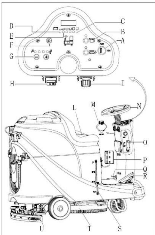
Figur 10
MASKINENS BRUG (SKURING OG T∅RRING)
natural_image
Top-down line drawing of a car showing front and side views with no text or symbolsFigur 11
Figur 13

Figur 14
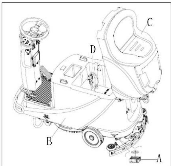
Figur 15
BRUG F∅RSTE GANG
SIKRINGSKONTROL/UDSKIFTNING
Figur 24
TROUBLESHOOTING
SÄILIÖN TYHJENNYS 213
KONEEN KÄYTÖN JÄLKEEN 213
KONEEN PITKÄ SEISOKKI 213
ENSIMMÄINEN KÄYTTÖKERTA....213
HUOLTO 214
MÄÄRÄAIKAISHUOLTOJEN AIKATAULU 214
AKUN LATAAMINEN 214
HARJAN/VETOALUSTAN PUHDISTAMINEN 215
LIUOKSEN SUODATTIMEN PUHDISTUS....216
IMUSUULAKKEEN PUHDISTAMINEN....216
SUULAKEKUMIEN TARKASTUS JA VAIHTO 216
YLITÄYTTÖSUOJAN PUHDISTUS JA KANNEN TIIVISTEEN TARKASTUS....217
SULAKKEEN TARKISTUS/VAIHTO 218
VARUSTEET/LISÄVARUSTEET 218
VIANETSINTÄ 218
KIERRÄTYS 220
JOHDANTO

HUOMAUTUS
flowchart
graph TD
    subgraph Power Supply
        A["Power Supply M2"] --> B["AC"]
        C["DC"] --> D["NC"]
        E["SW1"] --> F["SW3"]
        G["SW4"] --> H["SW5"]
        I["BU"] --> J["BU2"]
        K["SW6-A"] --> L["OR"]
        M["SW7"] --> N["SW8"]
        O["SW9"] --> P["SW10"]
        Q["SW11"] --> R["SW12"]
        S["SW13"] --> T["SW14"]
        U["SW15"] --> V["SW16"]
        W["SW17"] --> X["SW18"]
        Y["SW19"] --> Z["SW20"]
        AA["SW21"] --> AB["SW22"]
        AC["SW23"] --> AD["SW24"]
        AE["SW25"] --> AF["SW26"]
        AG["SW27"] --> AH["SW28"]
        AI["SW29"] --> AJ["SW30"]
        AK["SW31"] --> AL["SW32"]
        AM["SW33"] --> AN["SW34"]
        AO["SW35"] --> AP["SW36"]
        AQ["SW37"] --> AR["SW37"]
        AS["SW38"] --> AT["SW38"]
        AU["SW39"] --> AV["SW39"]
        AW["SW40"] --> AX["SW40"]
        AY["SW41"] --> AZ["SW41"]
        BA["SW42"] --> BB["SW42"]
        BC["SW43"] --> BD["SW43"]
        BE["SW44"] --> BF["SW44"]
        BG["SW45"] --> BH["SW45"]
        BI["SW46"] --> BJ["SW46"]
        BK["SW47"] --> BL["SW47"]
        BM["SW48"] --> BN["SW48"]
        BO["SW49"] --> BP["SW49"]
        BQ["SW50"] --> BR["SW50"]
        BS["SW51"] --> BT["SW51"]
        BU["SW52"] --> BV["SW52"]
        BW["SW53"] --> BX["SW53"]
        BY["SW54"] --> BZ["SW54"]
        CA["SW55"] --> CB["SW55"]
        CC["CURTIS 1212"] --> CD["KW5"]
    end
    subgraph Power Supply
        E
        G
        B
        W
        X
        Y
        Z
        AA
        AB
        AC
        AD
        AE
        BF
        BG
        BH
        BI
        BJ
        BA
        BB
    end
    subgraph Power Supply
        AC
        AD
        AE
        AF
        BG
        BH
    end
    subgraph Power Supply
        BI
        BJ
    end
| WIRE ROD | WIRE ROD | ||
| RD1 | RED/6AWG | BN/BK | BROWN/BLACK / 20AWG |
| RD2 | RED/10AWG | BU1 BL | UE/18AWG |
| RD3 | RED/18AWG | BU2 | BLUE/20AWG |
| RD4 | RED/20AWG | BU/BK | BLUE/BLACK / 20AWG |
| RD/BK | RED/BLACK / 20AWG | GN GREEN/20AWG | |
| BK1 | BLACK/6AWG | GN/BK | GREEN/BLACK /20AWG |
| BK2 | BLACK/10AWG | GY | GRAY/20AWG |
| BK3 | BLACK/12AWG | PU | PURPLE/20AWG |
| BK4 | BLACK/14AWG | OR ORANGE/20AWG | |
| BK5 | BLACK/18AWG | YE | YELLOW/20AWG |
| BN1 | BROWN/14AWG | WH1 | WHITE/12AWG |
| BN2 | BROWN/20AWG | WH2 | WHITE/20AWG |
| COMPONENTS | COMPONENTS | ||
| BAT | 24V BATTERIES | M1 | BRUSH MOTOR |
| CH | BATTERY CHARGER | M2 | VACUUM MOTOR |
| EB1 | CONTROL PANEL BOARD | M3 | DRIVE MOTOR |
| EB2 USB | CHARGING ELECTRONIC BOARD | SW1 | EMERGENCY-STOP SWITCH |
| EB3 | DRIVE ELECTRONIC BOARD | SW2 | KEY SWITCH |
| RL1 | BRUSH MOEOR ELECTROM SWITCH | SW3 | CLEAN WATER LEVEL SWITCH |
| RL2 | VACUUM MOEOR ELECTROM SWITCH | SW4 | VACUUM MOTOR SWITCH |
| RL3 | DRIVE SYSTEM ELECTROM SWITCH | SW5 | OPTIONAL MODE SWITCH |
| YV WATER ELECTROVALVE | OPTIONAL REVERSE SWITCH SW6-A | ||
| F1 | CONTROL PANEL BOARD FUSE | OPTIONAL REVERSE SWITCH SW6-B | |
| F2 | BRUSH MOTOR CIRCUIT BREAKER | SW7 | SEAT SWITCH |
| F3 | VACUUM MOTOR CIRCUIT BREAKER | SQ | FOOT THROTTLE |
| DRIVE SYSTEM CIRCUIT BREAKER F4 | SPK 12 | VDC BUZZER | |
| F5 | BRUSH RELEASE FUSE | VR SPEED POTENTIOMETER | |
| KA BRAKE | |||
| KOMPONENTIT | KOMPONENTIT | ||
| BAT | 24V AKUT | M1 | HARJAMOOTTORI |
| CH | AKKULATURI | M2 | IMUMOOTTORI |
| EB1 | OHJAUSPANEELIN PIIRILEVY | M3 | AJOMOOTTORI |
| EB2 | USB-LATURIN PIIRILEVY | SW1 | HÄTÄPYSÄYTYSKATKAISIN |
| EB3 | AJOMOOTTORIN PIIRILEVY | SW2 | VIRTAKYTKIN |
| RL1 | HARJAMOOTTORIN ELEKTRONINEN KYTKIN | SW3 | PUHTAAN VEDEN TASOKYTKIN |
| RL2 | IMUMOOTTORIN ELEKTRONINEN KYTKIN | SW4 | IMUMOOTTORIN KYTKIN |
| RL3 | AJOJÄRJESTELMÄN ELEKTRONINEN KYTKIN | SW5 | VALINNAINEN KÄYTTÖTILAN KYTKIN |
| YV | VEDEN SÄHKÖVENTTIILI | SW6-A | VALINNAINEN PERUUTUSKYTKIN |
| F1 | OHJAUSPANEELIN PIIRILEVYN SULAKE | SW6-B | VALINNAINEN PERUUTUSKYTKIN |
| F2 | AJOMOOTTORIN SULAKE | SW7 | ISTUIMEN KYTKIN |
| F3 | IMUMOOTTORIN SULAKE | SQ | JALKAKAASU |
| F4 | AJOJÄRJESTELMÄN SULAKE | SPK | 12V DC SUMMERI |
| F5 | HARJAN VAPAUTUKSEN SULAKE | VR | NOPEUDEN POTENTIOMETRI |
| KA | JARRU | ||
| VALSSILANKA | VALSSILANKA | ||
| RD1 | PUN./6AWG | BN/BK | RUSK./MUSTA / 20AWG |
| RD2 | PUN./10AWG | BU1 | SIN./18AWG |
| RD3 | PUN./18AWG | BU2 | SIN./20AWG |
| RD4 | PUN./20AWG | BU/BK | SIN./ MUSTA /20 AWG |
| RD/BK | PUN./MUSTA/20AWG | GN | VIHR./20AWG |
| BK1 | MUSTA/6AWG | GN/BK | VIHR./ MUSTA /20AWG |
| BK2 | MUSTA /10AWG | GY | HARMAA/20AWG |
| BK3 | MUSTA /12AWG | PU | VIOL./20AWG |
| BK4 | MUSTA /14AWG | OR | ORAN./20AWG |
| BK5 | MUSTA /18AWG | YE | KELT./20AWG |
| BN1 | RUSK./14AWG | WH1 | VALK./12 AWG |
| BN2 | RUSK./20AWG | WH2 | VALK./20AWG |
KÄYTTÖOHJEET

VAROITUS!
natural_image
Pure electrical circuit lines without any symbolsKuva 3
Kuva 4
Akun asennus
| Curve/Battery Type | SW1 | SW2 | ||
| D1 D2 D1 | D2 | |||
| IUla Wet | On | Off | Off | Off |
| IUla Gel Exide | Off | Off | ||
| IUoU AGM | Off | On | ||
| IUla AGM Discover | On | On | ||

| Curve/Battery Type | SW1 | SW2 | |||
| D1 | D2 | D1 | D2 | ||
| IUIa Wet | On | Off | Off | Off | |
| IUIa Gel Exide | Off | Off | |||
| IUUa AGM | Off | On | |||
| IUIa AGM Discover | On | On | |||
HÄTÄPYSÄYTYS
Kuva 7

VAROITUS!
Kuva 9

Kuva 10
natural_image
Top-down schematic of a car showing front and side views with no text or symbolsKuva 11
Kuva 13
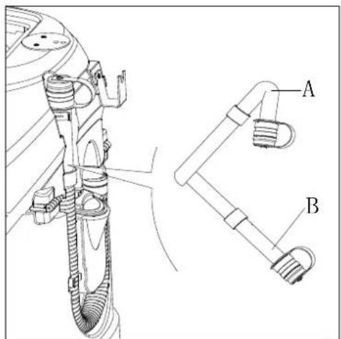
Kuva 14

Kuva 15
ENSIMMÄINEN KÄYTTÖKERTA
Kuva 24
VIANETSINTÄ
natural_image
Pure electrical circuit lines without any symbolsFigura 3
Figura 4
Figura 7
Figura 9

Figura 10
Parar a máquina
natural_image
Top-down line drawing of a car showing front and side views with no text or symbolsFigura 11
Figura 13
Figura 14
Figura 15
PRIMEIRA UTILIZAÇÃO
Figura 24
| WIRE ROD | WIRE ROD | ||
| RD1 | RED/6AWG | BN/BK | BROWN/BLACK / 20AWG |
| RD2 | RED/10AWG | BU1 BL | UE/18AWG |
| RD3 | RED/18AWG | BU2 | BLUE/20AWG |
| RD4 | RED/20AWG | BU/BK | BLUE/BLACK / 20AWG |
| RD/BK | RED/BLACK / 20AWG | GN GREEN/20AWG | |
| BK1 | BLACK/6AWG | GN/BK | GREEN/BLACK /20AWG |
| BK2 | BLACK/10AWG | GY | GRAY/20AWG |
| BK3 | BLACK/12AWG | PU | PURPLE/20AWG |
| BK4 | BLACK/14AWG | OR ORANGE/20AWG | |
| BK5 | BLACK/18AWG | YE | YELLOW/20AWG |
| BN1 | BROWN/14AWG | WH1 | WHITE/12AWG |
| BN2 | BROWN/20AWG | WH2 | WHITE/20AWG |
| COMPONENTS | COMPONENTS | ||
| BAT | 24V BATTERIES | M1 | BRUSH MOTOR |
| CH | BATTERY CHARGER | M2 | VACUUM MOTOR |
| EB1 | CONTROL PANEL BOARD | M3 | DRIVE MOTOR |
| EB2 | USB CHARGING ELECTRONIC BOARD | SW1 | EMERGENCY-STOP SWITCH |
| EB3 | DRIVE ELECTRONIC BOARD | SW2 | KEY SWITCH |
| RL1 | BRUSH MOEOR ELECTROM SWITCH | SW3 | CLEAN WATER LEVEL SWITCH |
| RL2 | VACUUM MOEOR ELECTROM SWITCH | SW4 | VACUUM MOTOR SWITCH |
| RL3 | DRIVE SYSTEM ELECTROM SWITCH | SW5 | OPTIONAL MODE SWITCH |
| YV WATER ELECTROVALVE | OPTIONAL REVERSE SWITCH SW6-A | ||
| F1 | CONTROL PANEL BOARD FUSE | OPTIONAL REVERSE SWITCH SW6-B | |
| F2 | BRUSH MOTOR CIRCUIT BREAKER | SW7 | SEAT SWITCH |
| F3 | VACUUM MOTOR CIRCUIT BREAKER | SQ | FOOT THROTTLE |
| DRIVE SYSTEM CIRCUIT BREAKER F4 | SPK 12VDC BUZZER | ||
| F5 | BRUSH RELEASE FUSE | VR SPEED POTENTIOMETER | |
| KA BRAKE | |||
natural_image
Pure electrical circuit lines without any symbolsΕικόνα 3
Εικόνα 7
Εικόνα 9

ΣΗΜΕΙΩΣΗ
Εικόνα 10

ΣΗΜΕΙΩΣΗ
natural_image
Top-down line drawing of a car showing front and side views with no text or symbolsΕικόνα 11
Εικόνα 13

Εικόνα 14
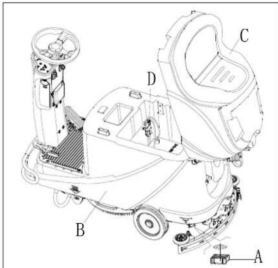
Εικόνα 15
Εικόνα 24
Αξεσουαρ / Επιλογες
natural_image
Pure electrical circuit lines without any symbolsSlika 3
Slika 4
| Curve/Battery Type | SW1 | SW2 | ||
| D1 D2 D1 | D2 | |||
| IUla Wet | On | Off | Off | Off |
| IUla Gel Exide | Off | Off | ||
| IUoU AGM | Off | On | ||
| IUla AGM Discover | On | On | ||

| Curve/Battery Type | SW1 | SW2 | |||
| D1 | D2 | D1 | D2 | ||
| IUIa Wet | On | Off | Off | Off | |
| IUIa Gel Exide | Off | Off | |||
| IUUa AGM | Off | On | |||
| IUIa AGM Discover | On | On | |||
ZAVIRANJE V SILI
Slika 7

Slika 8
Slika 9
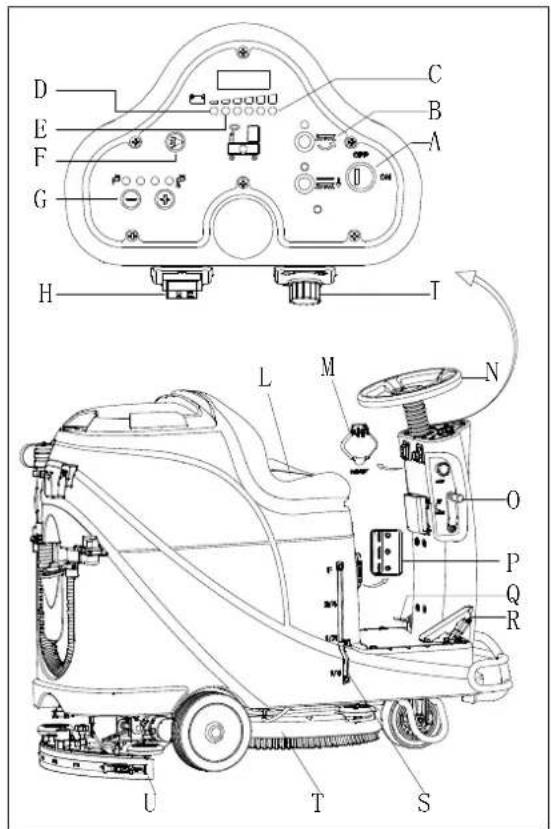
Slika 10
Zaustavitev naprave
natural_image
Top-down schematic of a car showing front and side views with no text or symbolsSlika 11
Polnjenje akumulatorja med delom
Slika 13
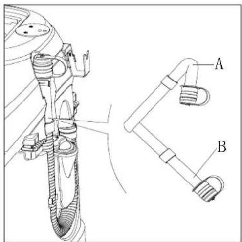
Slika 14
PO UPORABI NAPRAVE
Po delu, preden zapustite napravo:
Slika 15
PRVA UPORABA
TANK AND VACUUM GRID WITH FLOAT CLEANING, AND COVER GASKET CHECK
- Preverite celovitost tesnilnega traku rezervoarja.

OPOMBA
Tesnilni trak rezervoarja (G) ustvarja vakuum na notranji strani rezervoarja, ko deluje sesalni motor. Rezervoar mora biti zatesnjen, da lahko učinkovito absorbira vodo s tal v zbiralno posodo.
- Preverite, ali je kontaktna površina tesnilnega traku (G) cela in ali je tesnjenje zadostno. Po potrebi odtranite tesnilni trak z rezervoraja iz utora (H) in ga zamenjajte. Sestavite nov tesnilni trak, kot prikazuje Slika 23, sklep naj bo nazaj na sredini.
- Zaprite pokrov zbiralne posode (A).
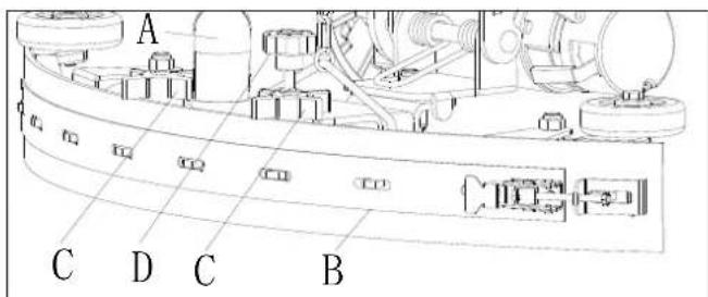
Slika 22

PREGLED/ZAMENJAVA VAROVALKE
Slika 24
ODPRAVLJANJE TEŽAV
DISPLEJ KONTROLKY NABÍJEČKY 291
TECHNICKÉ PARAMETRY 292
SCHÉMA ZAPOJENÍ......293
PROVOZNÍ PŘÍRUČKA 295
INSTALACE A INSTALACE NOVÉ BATERIE PŘÍSTROJE 295
VLOŽENÍ BATERIÍ A NASTAVENÍ TYPU BATERIÍ (MOKRÉ NEBO GELOVÉ/AGM) 295
NOUZOVÉ ZASTAVENÍ 297
INSTALACE A ODINSTALACE DRŽÁKU KARTÁČE/PODLOŽKY 297
NASTAVENÍ VYVÁŽENÍ SACÍ TRYSKY....298
PLNĚNÍ NÁDRŽE S ČISTICÍM PROSTŘEDKEM 298
SPUŠTĚNÍ A ZASTAVENÍ PŘÍSTROJE 299
OBSLUHA PŘÍSTROJE (ČIŠTĚNÍ A VYSOUŠENÍ) 300
VYPRÁZDNĚNÍ NÁDRŽE 301
PO POUŽITÍ PŘÍSTROJE 301
DLOUHÁ NEČINNOST PŘÍSTROJE 301
PRVNÍ POUŽITÍ PŘÍSTROJE 302
ÚDRŽBA 302
TABULKA PLÁNOVANÉ ÚDRŽBY 302
NABÍJENÍ BATERIÍ 302
ČIŠTĚNÍ KARTÁČE/PODLOŽKY 303
ČIŠTĚNÍ FILTRU NÁDRŽE S ČISTICÍM PROSTŘEDKEM ......304
PŘÍSLUŠENSTVÍ/MOŽNOSTI 306
ŘEŠENÍ POTÍŽÍ 306
LIKVIDACE 308
ÚVOD

POZNÁMKA
INSTALACE A INSTALACE NOVÉ BATERIE PŘÍSTROJE

VAROVÁNÍ!
natural_image
Pure electrical circuit lines without any symbolsObrázek 3
Obrázek 4
Vložení baterií
| Curve/Battery Type | SW1 | SW2 | ||
| D1 | D2 | D1 | D2 | |
| IUla Wet | On | Off | Off | Off |
| IUla Gel Exide | Off | Off | ||
| IUoU AGM | Off | On | ||
| IUla AGM Discover | On | On | ||

| Curve/Battery Type | SW1 | SW2 | ||
| D1 | D2 | D1 | D2 | |
| IUIa Wet | On | Off | Off | Off |
| IUIa Gel Exide | Off | Off | ||
| IUUa AGM | Off | On | ||
| IUIa AGM Discover | On | On | ||
NOUZOVÉ ZASTAVENÍ
Obrázek 7
PLNĚNÍ NÁDRŽE S ČISTICÍM PROSTŘEDKEM
Obrázek 8
Obrázek 9

Obrázek 10
Zastavení prístroje
natural_image
Top-down line drawing of a car showing front and side views with no text or symbolsObrázek 11
DLOUHÁ NEČINNOST PŘÍSTROJE
Obrázek 13
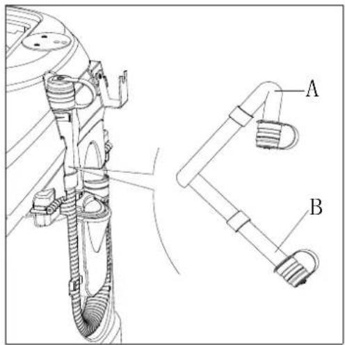
Obrázek 14

Obrázek 15
PRVNÍ POUŽITÍ PŘÍSTROJE
PŘÍSLUŠENSTVÍ/MOŽNOSTI
PŘÍSLUŠENSTVÍ/MOŽNOSTI
Obrázek 24
ŘEŠENÍ POTÍŽÍ
flowchart
graph TD
    subgraph Power Supply
        A["Power Supply M2"] --> B["AC"]
        C["DC"] --> D["NC"]
        E["SW1"] --> F["SW3"]
        G["SW4"] --> H["SW5"]
        I["BU"] --> J["BU2"]
        K["SW6-A"] --> L["OR"]
        M["SW7"] --> N["SW8"]
        O["SW9"] --> P["SW10"]
        Q["SW11"] --> R["SW12"]
        S["SW13"] --> T["SW14"]
        U["SW15"] --> V["SW16"]
        W["SW17"] --> X["SW18"]
        Y["SW19"] --> Z["SW20"]
        AA["SW21"] --> AB["SW22"]
        AC["SW23"] --> AD["SW24"]
        AE["SW25"] --> AF["SW26"]
        AG["SW27"] --> AH["SW28"]
        AI["SW29"] --> AJ["SW30"]
        AK["SW31"] --> AL["SW32"]
        AM["SW33"] --> AN["SW34"]
        AO["SW35"] --> AP["SW36"]
        AQ["SW37"] --> AR["SW37"]
        AS["SW38"] --> AT["SW38"]
        AU["SW39"] --> AV["SW39"]
        AW["SW40"] --> AX["SW40"]
        AY["SW41"] --> AZ["SW41"]
        BA["SW42"] --> BB["SW42"]
        BC["SW43"] --> BD["SW43"]
        BE["SW44"] --> BF["SW44"]
        BG["SW45"] --> BH["SW45"]
        BI["SW46"] --> BJ["SW46"]
        BK["SW47"] --> BL["SW47"]
        BM["SW48"] --> BN["SW48"]
        BO["SW49"] --> BP["SW49"]
        BQ["SW50"] --> BR["SW50"]
        BS["SW51"] --> BT["SW51"]
        BU["SW52"] --> BV["SW52"]
        BW["SW53"] --> BX["SW53"]
        BY["SW54"] --> BZ["SW54"]
        CA["SW55"] --> CB["SW55"]
        CC["CURTIS 1212"] --> CD["KW5"]
    end
    subgraph Power Supply
        E
        G
        B
        W
        X
        Y
        Z
        AA
        AB
        AC
        AD
        AE
        BF
        BG
        BH
        BI
        BJ
        BA
        BB
    end
    subgraph Power Supply
        AC
        AD
        AE
        AF
        BG
        BH
    end
    subgraph Power Supply
        BI
        BJ
    end
| WIRE ROD | WIRE ROD | ||
| RD1 | RED/6AWG | BN/BK | BROWN/BLACK / 20AWG |
| RD2 | RED/10AWG | BU1 BL | UE/18AWG |
| RD3 | RED/18AWG | BU2 | BLUE/20AWG |
| RD4 | RED/20AWG | BU/BK | BLUE/BLACK / 20AWG |
| RD/BK | RED/BLACK / 20AWG | GN GREEN/20AWG | |
| BK1 | BLACK/6AWG | GN/BK | GREEN/BLACK /20AWG |
| BK2 | BLACK/10AWG | GY | GRAY/20AWG |
| BK3 | BLACK/12AWG | PU | PURPLE/20AWG |
| BK4 | BLACK/14AWG | OR ORANGE/20AWG | |
| BK5 | BLACK/18AWG | YE | YELLOW/20AWG |
| BN1 | BROWN/14AWG | WH1 | WHITE/12AWG |
| BN2 | BROWN/20AWG | WH2 | WHITE/20AWG |
| COMPONENTS | COMPONENTS | ||
| BAT | 24V BATTERIES | M1 | BRUSH MOTOR |
| CH | BATTERY CHARGER | M2 | VACUUM MOTOR |
| EB1 | CONTROL PANEL BOARD | M3 | DRIVE MOTOR |
| EB2 USB | CHARGING ELECTRONIC BOARD | SW1 | EMERGENCY-STOP SWITCH |
| EB3 | DRIVE ELECTRONIC BOARD | SW2 | KEY SWITCH |
| RL1 | BRUSH MOEOR ELECTROM SWITCH | SW3 | CLEAN WATER LEVEL SWITCH |
| RL2 | VACUUM MOEOR ELECTROM SWITCH | SW4 | VACUUM MOTOR SWITCH |
| RL3 | DRIVE SYSTEM ELECTROM SWITCH | SW5 | OPTIONAL MODE SWITCH |
| YV WATER ELECTROVALVE | OPTIONAL REVERSE SWITCH SW6-A | ||
| F1 | CONTROL PANEL BOARD FUSE | OPTIONAL REVERSE SWITCH SW6-B | |
| F2 | BRUSH MOTOR CIRCUIT BREAKER | SW7 | SEAT SWITCH |
| F3 | VACUUM MOTOR CIRCUIT BREAKER | SQ | FOOT THROTTLE |
| DRIVE SYSTEM CIRCUIT BREAKER F4 | SPK 12 | VDC BUZZER | |
| F5 | BRUSH RELEASE FUSE | VR SP | EED POTENTIOMETER |
| KA BRAKE | |||
| ELEMENTY | ELEMENTY | ||
| BAT | AKUMULATORY 24V | M1 | SILNIK SZCZOTKI |
| CH | ŁADOWARKA DO AKUMULATORÓW | M2 | SILNIK SSAWY |
| EB1 | PŁYTKA STEROWANIA | M3 | SILNIK NAPĘDOWY |
| EB2 | PŁYTKA ELEKTRONICZNA ŁADOWARKI USB | SW1 | WYŁĄCZNIK AWARYJNY |
| EB3 | PŁYTKA ELEKTRONICZNA NAPĘDU | SW2 | PRZEŁĄCZNIK KLUCZYKOWY |
| RL1 | WŁĄCZNIK ELECTROM SILNIKA SZCZOTKI | SW3 | POZIOMOWSKAZ CZYSTEJ WODY |
| RL2 | WŁĄCZNIK ELECTROM SILNIKA SSAWY | SW4 | WŁĄCZNIK SILNIKA SSAWY |
| RL3 | WŁĄCZNIK ELECTROM SYSTEMU NAPĘDU | SW5 | OPCJONALNY WŁĄCZNIK TRYBU |
| YV | ELEKTYOZAWÓR WODY | SW6-A | OPCJONALNY WĄCZNIK COFANIA |
| F1 | BEZPIECZNIK PŁYTKI STEROWANIA | SW6-B | OPCJONALNY WĄCZNIK COFANIA |
| F2 | WYŁĄCZNIK AUTOMAT. OBWODU SILNIKA SZCZOTKI | SW7 | WYŁĄCZNIK SIEDZISKA |
| F3 | WYŁĄCZNIK AUTOMAT. SILNIKA SSAWY | SQ | PRZEPUSTNICA PRZY STOPIE |
| F4 | WYŁĄCZNIK AUTOM. SYSTEMU NAPĘDU | SPK | BRZĘCZYK 12 VDC |
| F5 | BEZPIECZNIK ZWOLNIENIA SZCZOTKI | VR | POTENCJOMETR REGULACJI PRĘDKOŚCI |
| KA | HAMULEC | ||
| PRZEWÓD | PRZEWÓD | ||
| RD1 | CZERWONY/6AWG | BN/BK | BRAŻOWY/CZARNY/20AWG |
| RD2 | CZERWONY/10AWG | BU1 | NIEBIESKI/18AWG |
| RD3 | CZERWONY/18AWG | BU2 | NIEBIESKI/20AWG |
| RD4 | CZERWONY/20AWG | BU/BK | NIEBIESKI/CZARNY/20AWG |
| RD/BK | CZERWONY/CZARNY/20AWG | GN | ZIELONY/20AWG |
| BK1 | CZARNY/6AWG | GN/BK | ZIELONY/CZARNY/20AWG |
| BK2 | CZARNY/10AWG | GY | SZARY/20AWG |
| BK3 | CZARNY/12AWG | PU | FIOLET/20AWG |
| BK4 | CZARNY/14AWG | OR | POMARAŃCZ/20AWG |
| BK5 | CZARNY/18AWG | YE | ŻÓŁTY/20AWG |
| BN1 | BRAŻOWY/14AWG | WH1 | BIAŁY/12AWG |
| BN2 | BRAŻOWY/20AWG | WH2 | BIAŁY/20AWG |
SPOSÓB UŻYCIA

OSTRZEŻENIE!
natural_image
Pure electrical circuit lines without any symbolsRys. 3
Rys. 4
NAPEŁNIANIE ZBIORNIKA NA ROZTWÓR
Rys. 7
Rys. 9

Rys. 10
natural_image
Top-down line drawing of a car showing front and side views with no text or symbolsRys. 11
Rys. 13

Rys. 14

Rys. 15
PIERWSZE UŻYCIE

INFORMACJA
KONTROLA I WYMIANA BEZPIECZENIKÓW
Rys. 24
USUWANIE USTEREK
natural_image
Pure electrical circuit lines without any symbolsÁbra 3
Ábra 4
| Curve/Battery Type | SW1 | SW2 | ||
| D1 D2 D1 | D2 | |||
| IUla Wet | On | Off | Off | Off |
| IUla Gel Exide Off Off | ||||
| IUoU AGM | Off On | |||
| IUla AGM Discover | On | On | ||
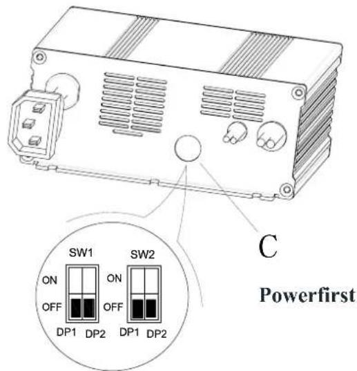
| Curve/Battery Type | SW1 | SW2 | |||
| D1 | D2 | D1 | D2 | ||
| IUIa Wet | On | Off | Off | Off | |
| IUIa Gel Exide Off Off | |||||
| IUUa AGM | Off | On | |||
| IUIa AGM Discover | On | On | |||
VÉSZFÉKEZŐ
Ábra 7

FIGYELEM!
Ábra 9

Ábra 10
A gép leállítása
natural_image
Top-down line drawing of a car showing front and side views with no text or symbolsÁbra 11
Ábra 13
Ábra 14
Ábra 15
HASZNÁLAT AZ ELSŐ ALKALOMMAL

MEGJEGYZÉS
BIZTOSÍTÉK ELLENÓRZÉSE/CSERÉJE
Ábra 24
HIBAELHÁRÍTÁS
INFORMATII AFIŞAJ ECRAN LED
natural_image
Pure electrical circuit lines without any symbolsFigura 3
| Curve/Battery Type | SW1 | SW2 | |||
| D1 | D2 | D1 | D2 | ||
| IUla Wet | On | Off | Off | Off | |
| IUla Gel Exide | Off | Off | |||
| IUoU AGM | Off | On | |||
| IUla AGM Discover | On | On | |||
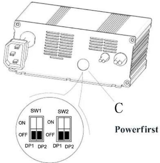
| Curve/Battery Type | SW1 | SW2 | |||
| D1 | D2 | D1 | D2 | ||
| IUIa Wet | On | Off | Off | Off | |
| IUIa Gel Exide | Off | Off | |||
| IUUa AGM | Off | On | |||
| IUIa AGM Discover | On | On | |||
FRÂNAREA ÎN CAZ DE URGENTĂ
Figura 7
UMPLEREA REZERVORULUI DE SOLUȚIE
Figura 9
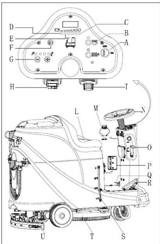
Figura 10
Oprirea maşinii
natural_image
Top-down schematic of a car showing front and side views with no text or symbolsFigura 11
Figura 13
Figura 14
Figura 15
PRIMA UTILIZARE
Please charge the batteries when the yellow LED (32) or red LED (33) is on, or at the end of each working cycle.

ATENTIE
VERIFICAREA/ÎNLOCUIREASIGURANTEI ELECTRICE
Figura 24
DEPANARE
natural_image
Pure electrical circuit lines without any symbols
ЗАБЕЛЕЖКА
Фигура 4
Фигура 7
ПЪЛНЕНЕ НА РЕЗЕРВОАРА ЗА ПОЧИСТВАЩ РАЗТВОР
Фигура 9

ЗАБЕЛЕЖКА
Фигура 10
natural_image
Top-down line drawing of two cars on a grid surface, showing front and side views with no text or symbolsФигура 11
Фигура 13
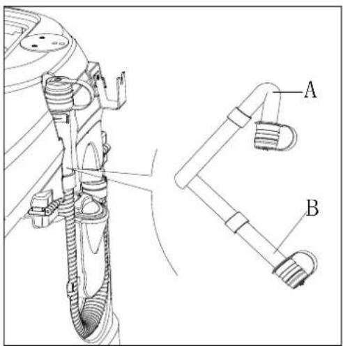
Фигура 14

Фигура 15
ПЪРВО ИЗПОЛЗВАНЕ
Фигура 24
Аксесоари/Приставки
| WIRE ROD | WIRE ROD | ||
| RD1 | RED/6AWG | BN/BK | BROWN/BLACK / 20AWG |
| RD2 | RED/10AWG | BU1 BL | UE/18AWG |
| RD3 | RED/18AWG | BU2 | BLUE/20AWG |
| RD4 | RED/20AWG | BU/BK | BLUE/BLACK / 20AWG |
| RD/BK | RED/BLACK / 20AWG | GN GREEN/20AWG | |
| BK1 | BLACK/6AWG | GN/BK | GREEN/BLACK /20AWG |
| BK2 | BLACK/10AWG | GY | GRAY/20AWG |
| BK3 | BLACK/12AWG | PU | PURPLE/20AWG |
| BK4 | BLACK/14AWG | OR ORANGE/20AWG | |
| BK5 | BLACK/18AWG | YE | YELLOW/20AWG |
| BN1 | BROWN/14AWG | WH1 | WHITE/12AWG |
| BN2 | BROWN/20AWG | WH2 | WHITE/20AWG |
| COMPONENTS | COMPONENTS | ||
| BAT | 24V BATTERIES | M1 | BRUSH MOTOR |
| CH | BATTERY CHARGER | M2 | VACUUM MOTOR |
| EB1 | CONTROL PANEL BOARD | M3 | DRIVE MOTOR |
| EB2 | USB CHARGING ELECTRONIC BOARD | SW1 | EMERGENCY-STOP SWITCH |
| EB3 | DRIVE ELECTRONIC BOARD | SW2 | KEY SWITCH |
| RL1 | BRUSH MOEOR ELECTROM SWITCH | SW3 | CLEAN WATER LEVEL SWITCH |
| RL2 | VACUUM MOEOR ELECTROM SWITCH | SW4 | VACUUM MOTOR SWITCH |
| RL3 | DRIVE SYSTEM ELECTROM SWITCH | SW5 | OPTIONAL MODE SWITCH |
| YV WATER ELECTROVALVE | OPTIONAL REVERSE SWITCH SW6-A | ||
| F1 | CONTROL PANEL BOARD FUSE | OPTIONAL REVERSE SWITCH SW6-B | |
| F2 | BRUSH MOTOR CIRCUIT BREAKER | SW7 | SEAT SWITCH |
| F3 | VACUUM MOTOR CIRCUIT BREAKER | SQ | FOOT THROTTLE |
| DRIVE SYSTEM CIRCUIT BREAKER F4 | SPK 12VDC BUZZER | ||
| F5 | BRUSH RELEASE FUSE | VR SPEED POTENTIOMETER | |
| KA BRAKE | |||
natural_image
Pure electrical circuit lines without any symbolsРисунок 3
Рисунок 4
Установка батареи
| Curve/Battery Type | SW1 | SW2 | ||
| D1 D2 D1 | D2 | |||
| IUla Wet | On | Off | Off | Off |
| IUla Gel Exide Off Off | ||||
| IUoU AGM | Off On | |||
| IUla AGM Discover | On | On | ||
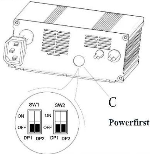
| Curve/Battery Type | SW1 | SW2 | |||
| D1 | D2 | D1 | D2 | ||
| IUIa Wet | On | Off | Off | Off | |
| IUIa Gel Exide Off Off | |||||
| IUUa AGM | Off | On | |||
| IUIa AGM Discover | On | On | |||
Рисунок 7
Рисунок 9
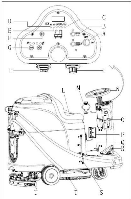
Рисунок 10
Остановка машины
natural_image
Top-down schematic of a car showing front and side views with no text or symbolsРисунок 11
Зарядка батарей
Рисунок 13
Рисунок 14
Рисунок 15
Рисунок 24
ŠTRUKTÚRA STROJA....403
OVLÁDACÍ PANEL 404
INFORMÁCIE DISPLEJA LED OBRAZOVKY 404
ZOBRAZENIE INDIKÁTOROV NABÍJAČKY 404
TECHNICKÉ PARAMETRE....405
SCHÉMA ZAPOJENIA 406
PREVÁDZKOVÁ PRÍRUČKA 408
VLOŽENIE A NASTAVENIE NOVEJ BATÉRIE ZARIADENIA 408
VLOŽENIE BATÉRIE A NASTAVENIE TYPU BATÉRIE (WET ALEBO GEL/AGM) 408
NÚDZOVÉ ZABRZDENIE....409
NAMONTOVANIE A ODMONTOVANIE KEFY/MOPU 409
NASTAVENIE ROVNOVÁHY LIŠTY 410
AK JE STROJ DLHO NEČINNÝ 413
POUŽITIE PRVÝKRÁT 414
ÚDRŽBA 414
TABULKA PLÁNU ÚDRŽBY 414
NABÍJANIE BATÉRIÍ....414
ČISTENIE KEFY/PADU 415
ČISTENIE FILTRA NA ROZTOK....416
ČISTENIE LIŠTY 416
KONTROLA A VÝMENA ČEPELÍ LIŠTY....416
ČISTENIE NÁDRŽE A SACEJ MRIEŽKY S PLAVÁKOM A KONTROLA TESNENIA VEKA 417
KONTROLA/VÝMENA POISTKY 418
PRÍSLUŠENSTVO/MOŽNOSTI 418
RIEŠENIE PROBLÉMOV......418
LIKVIDÁCIA....420
ÚVOD

POZNÁMKA
The copies of the original declaration of conformity are provided together with the machine documentation.
PRÍSLUŠENSTVO A ÚDRŽBA
natural_image
Pure electrical circuit lines without any symbolsObrázok 3
| Curve/Battery Type | SW1 | SW2 | ||
| D1 | D2 | D1 | D2 | |
| IUla Wet | On | Off | Off | Off |
| IUla Gel Exide | Off | Off | ||
| IUoU AGM | Off | On | ||
| IUla AGM Discover | On | On | ||
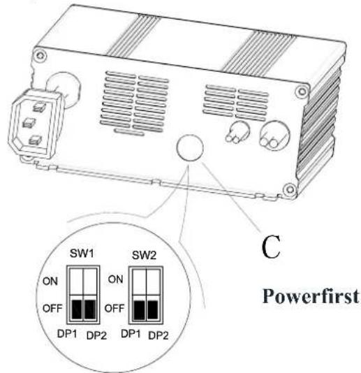
| Curve/Battery Type | SW1 | SW2 | |||
| D1 | D2 | D1 | D2 | ||
| IUIa Wet | On | Off | Off | Off | |
| IUIa Gel Exide | Off | Off | |||
| IUUa AGM | Off | On | |||
| IUIa AGM Discover | On | On | |||
NÚ DZOVÉ ZABRZDENIE
Naplnenie nádrže na roztok
Obrázok 9
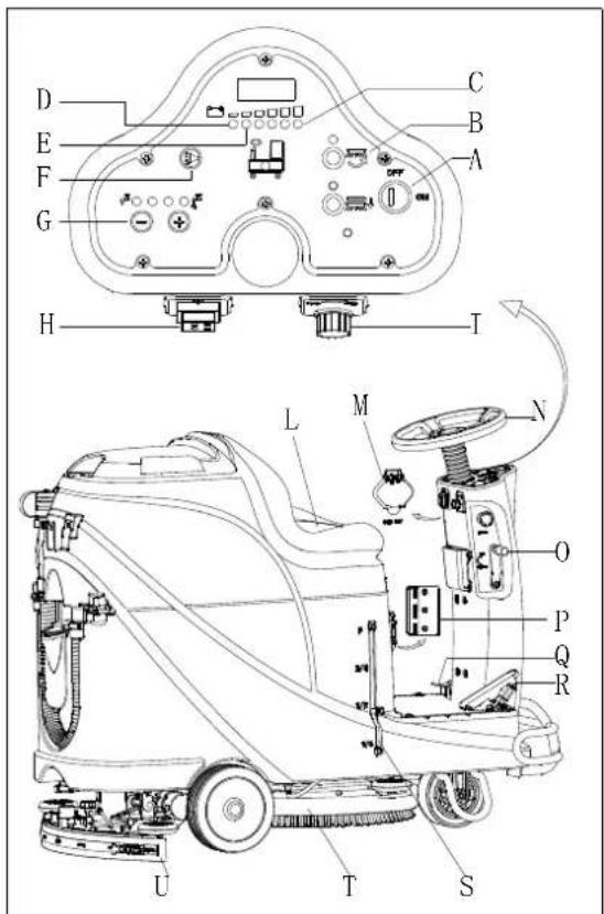
Obrázok 10
Zastavenie stroja
natural_image
Top-down schematic of a car showing front and side views with no text or symbolsObrázok 11
Obrázok 13
Obrázok 14
AK JE STROJ DLHO NEČINNÝ
Obrázok 15
POUŽITIE PRVÝKRÁT
Obrázok 24
RIEŠENIE PROBLÉMOV
| Problém | Pravdepodobné príčiny | Riešenie |
| Motor nepracuje; nezapne sa žiadne varovné svetlo (C9) | Konektor batérie je odpojený | Pripojte konektor batérie |
| Batérie sú úplne vybité | Nabite batérie | |
| Stroj nepracuje, zapne sa červená varovná kontrolka kapacity batérie (C8) | Úroveň nabitia batérií je príliš nízka | Nabite batérie |
| Stroj nejde vpred / vzad | Riadiaca doska má poruchu | Vymeňte riadiacu dosku |
| Ovládač pohonného motora má poruchu | Pozrite si “INFORMÁCIE O CHYBOVÝCH HLÁSENIACH POHONNÉHO MOTORA” | |
| Obsluhujúca osoba nie je na sedadle | Sadnite si na sedadlo | |
| Lišta nie je nadvihnutá, ked’ stroj ide vzad | Nadvihnite lištu | |
| Motor kefy nepracuje | Riadiaca doska má poruchu | Vymeňte riadiacu dosku |
| Motor kefy je preťažený | Použite jemnú kefku, ktorá je vhodná na čistenie, a resetujte ochranu pred preťažením motora kefy | |
| Relé motora kefy má poruchu | Kontaktujte popredajný servis | |
| Opotrebovanie karbónovej kefy motora kefy | Kontaktujte popredajný servis | |
| Prekážky bránia kefe v otáčaní | Vyčistite kefu | |
| Pohonný motor nepracuje | Zapne sa kontrolka pre problém pohonného motora | Pozrite si “INFORMÁCIE O CHYBOVÝCH HLÁSENIACH POHONNÉHO MOTORA” |
| Preťaaženie pohonného motora | Resetujte ochranu pred preťažením pohonného motora a skontrolujte pohonný motor/obvod | |
| Motor sania nepracuje | Preťaženie motora sania | Resetujte ochranu pred preťažením motora sania a skontrolujte motor sania |
| Relé motora sania má poruchu | Kontaktujte popredajný servis | |
| Riadiaca doska má poruchu | Vymeňte riadiacu dosku | |
| Nedostatočné sanie, podlaha sa nesuší | Nádrž na špinavú vodu je plná | Vyprázdnite nádrž na špinavú vodu |
| Zlé prepojenie odtokovej hadice a lišty | Správne spojte odtokovú hadicu a lištu | |
| Zablokovaný filter plaváku | Vyčistite filter plaváku a skontrolujte stav polohy plaváku | |
| Lišta je špinavá alebo opotrebovaná | Skontrolujte a vyčistite lištu | |
| Kryt nádrže na špinavú vodu nie je riadne zatvorený, alebo je tesnenie poškodené, alebo je ohyb trubice upchatý | Riadne zatvorte kryt, alebo vymeňte tesnenie, alebo vyčistite ohyb trubice | |
| Nádrž na špinavú vodu je špinavá | Vyčistite nádrž na špinavú vodu | |
| Nedostatočná dodávka roztoku na plochu kefy | Roztokový filter je špinavý | Vyčistite filter |
| Zapne sa kontrolka, že je nádrž na roztok prázdna | Naplňte nádrž na roztok | |
| Nádrž na roztok je príliš špinavá | Vyčistite nádrž na roztok | |
| Lišta necháva škrabance na podlahe | Pod čepelou lišty je nečistota | Odstráněte nečistotu |
| Čepel' lišty je opotrebovaná, popraskaná | Vymeňte čepele lišty | |
| Nie je nastavené vyváženie lišty | Nastavte vyváženie lišty | |
| Nefunguje brzda pohonného motora | Brzda je uzamknutá | Nastavte brzdu na uvoľnenú |
natural_image
Pure electrical circuit lines without any symbolsŞekil 3
Şekil 4
Batarya yerleştirme
| Curve/Battery Type | SW1 | SW2 | ||
| D1 D2 D1 | D2 | |||
| IUla Wet | On | Off | Off | Off |
| IUla Gel Exide Off Off | ||||
| IUoU AGM | Off On | |||
| IUla AGM Discover | On | On | ||
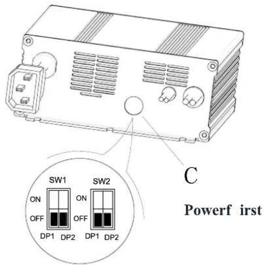
| Curve/Battery Type | SW1 | SW2 | |||
| D1 | D2 | D1 | D2 | ||
| IUIa Wet | On | Off | Off | Off | |
| IUIa Gel Exide Off Off | |||||
| IUUa AGM | Off | On | |||
| IUIa AGM Discover | On | On | |||
ACİL DURUM FRENLEMESİ
Şekil 7
SOLÜSYON TANKI DOLDURMA
Şekil 9

Şekil 10
natural_image
Top-down line drawing of a car showing front and side views with no text or symbolsŞekil 11
Şekil 13
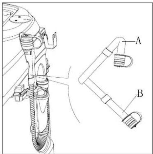
Şekil 14

Şekil 15
İLK KULLANIM
Şekil 24
SORUN GİDERME
Viper Cleaning Equipment Co. Ltd.
Viper Industrial Estate
Liangbian, Liaobu,
Dongguan, Guangdong
START I STOP STROJA....455
UPORABA STROJA (ISPIRANJE I SUŠENJE)......456
PRAŽNJENJE SPREMNIKA....457
NAKON UPORABE STROJA 457
DUŽA NEAKTIVNOST STROJA....457
KORISTENJE PRVI PUT 458
ODRŽAVANJE 458
TABELA RASPOREDA ODRŽAVANJA 458
PUNJENJE BATERIJE 458
ČIŠCENJE ČETKE / JASTUKA 459
ČIŠĆENJE FILTRA OTOPINE....460
ČIŠĆENJE USISNIKA 460
PROVJERAVANJE I ZAMJENA LOPATICA USISNIKA 460
PROVJERA REŠETKE SPREMNIKA/ USISNIKA PLUTAJUĆEG PLOVKA I BRTVENE TRAKE 461
PROVJERA / ZAMJENA OSIGURAČA 462
PRIBOR / OPCIJE 462
RJEŠAVANJE PROBLEMA....462
IZBACITI IZ UPORABE 464
UVOD

BILJEŠKA
Brojevi u zagradama odnose se na komponente prikazane u poglavlju Opis stroja.
SADRŽAJ I SVRHA PRIRUČNIKA
natural_image
Pure electrical circuit lines without any symbolsSlika 3
Slika 4
Instalacija baterije
| Curve/Battery Type | SW1 | SW2 | ||
| D1 | D2 | D1 | D2 | |
| IUla Wet | On | Off | Off | Off |
| IUla Gel Exide | Off | Off | ||
| IUoU AGM | Off | On | ||
| IUla AGM Discover | On | On | ||
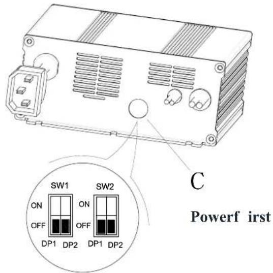
| Curve/Battery Type | SW1 | SW2 | ||
| D1 | D2 | D1 | D2 | |
| IUIa Wet | On | Off | Off | Off |
| IUIa Gel Exide | Off | Off | ||
| IUUa AGM | Off | On | ||
| IUIa AGM Discover | On | On | ||
PRINUNDO KOČENJE
PUNJENJE SPREMNIKA OTOPINE
Slika 7
-
Otvorite poklopac za ulaz vode (E, Slika 8).
-
Punjenje prikladne vode ili otopine kroz ulaz vode s filtrom. Temperatura otopine ne smije prijeći + 104F (+ 40°C).
-
Nemojte pretjerano puniti spremnik, pogledajte indikator razine (G) za količinu vode.

UPOZORENJE!
Koristite samo nezapaljive deterdžente sa malo pjene i namijenjene automatskim sredstvima za pranje.
Slika 8
• Kočnica je aktivirana - poluga je na dole
Slika 9
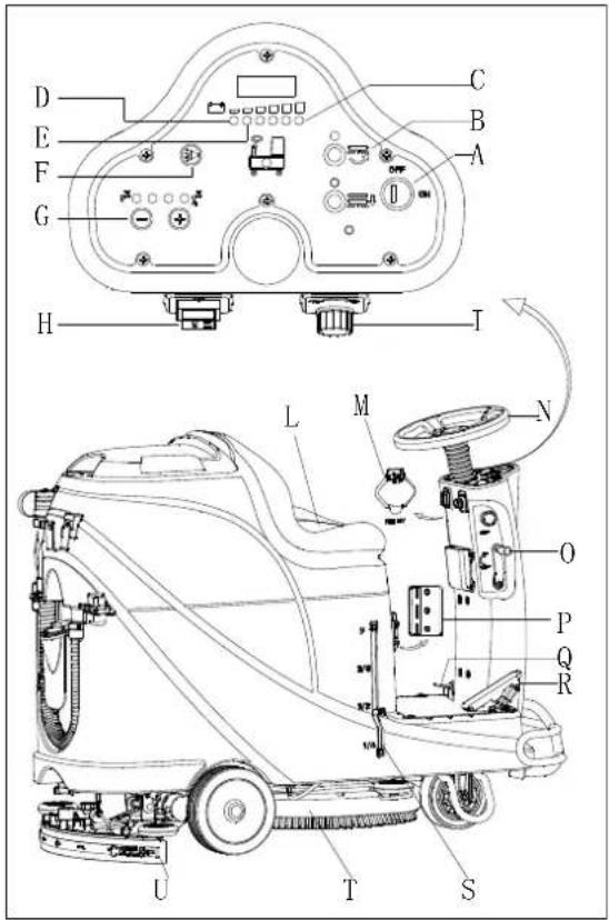
Slika 10
UPORABA STROJA (ISPIRANJE I SUŠENJE)
natural_image
Top-down line drawing of two cars on a grid background, showing front and side views with no text or symbolsSlika 11
Slika 13
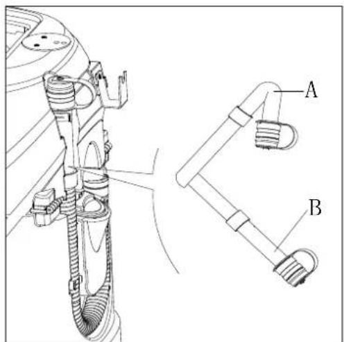
Slika 14
Otopina / pražnjenje čistog spremnika vode
- Izvedite korake 1 do 4 u poglavlju "pražnjenje povratnog spremnika vode".
- Ispraznite spremnik otopine kroz poklopac (A, Slika 15). I zatim isperite spremnik čistom vodom.
NAKON UPORABE STROJA
Slika 15
KORIŠTENJE PRVI PUT

BILJEŠKA
PROVJERA / ZAMJENA OSIGURAČA
- Okrenite prekidač za ključ (D, Slika 24) na "OFF".
- Odspojite kabel za spajanje baterije.
- Odvijte vijke (C) na upravljačkoj ploči i zatim okrenite PCBA da pronađe osigurač (A i B).
- Provjerite / zamijenite osigurače:
A) F1 je osigurač sklopa male snage (5A)
B) F3 je osigurač za skidanje četke (20A) - Nakon provjere / zamjene, ponovno sastavite obrnutim redoslijedom.
- Provjerite ili resetirajte zaštitnik opterećenja motora.
E) F5 je zaštitnik za preopterećenje usisnog motora (30A)
F) F4 je štitnik za preopterećenje pogonskog motora (30A)
G) F2 je zaštitnik za preopterećenje motora četke (30A)
PRIBOR / OPCIJE
Pored standardnih komponenti, stroj može biti opremljen sljedećim priborom / opcijama, ovisno o uporabi stroja.
Za daljnje informacije o gore spomenutom dodatnom priboru, obratite se ovlaštenom prodavaču.
Pribor / opcije
Slika 24
RJEŠAVANJE PROBLEMA
| Problem | Mogući uzroci | Rješenje |
| Motori ne rade; nema svjetla upozorenja (C9) | Priključak baterije je isključen | Spojite priključak baterije |
| Baterije su potpuno prazne | Napunite baterije | |
| Stroj ne radi, žaruljica upozorenja o crvenoj bateriji se uključuje (C8) | Razina baterije je preniska | Napunite baterije |
| Stroj ne ide naprijed/natrag | Greška upravljačke ploče | Zamijenite ploču |
| Greška u upravljačkom pogonu motora | Pogledajte "POKAZATELJI INDIKATORA POGREŠKE MOTORA" | |
| Operater nije na sjedalu | Sjednite na sjedalo | |
| Usisnik se ne podiže tijekom rada stroja unatrag | Podignite usisnik | |
| Motor četke ne radi | Greška upravljačke ploče | Zamijenite ploču |
| Preopterećenja motora četke | Koristite meku četkicu čekinja koja je prikladna za čišćenje i sprovedite resetiranje zaštitnog opterećenja motora četkice | |
| Greška kvara kontaktora s četkom | Kontaktirajte servis | |
| Istrošena ugljična četkica | Kontaktirajte servis | |
| Prepreke sprječavaju rotaciju četke | Očistite četku | |
| Pogonski motor ne radi | Ukljućuje se svjetlo smetnje motora pogona | Pogledajte "POKAZATELJI INDIKATORA POGREŠKE MOTORA" |
| Preopterećenje pogonskog motora | Ponovno namjestite zaštitnik od preopterećenja motora pogona i provjerite motor / krug pogona | |
| Usisni motor ne radi | Preopterećenje usisnog motora | Ponovno postavite zaštitnik od preopterećenja usisnog motora i provjerite usisni motor |
| Kvar releja usisnog motora | Kontaktirajte servis | |
| Greška upravljačke ploče | Zamijenite upravljačku ploču | |
| Nedovoljno usisavanje, pod se ne može osušiti | Povratni spremnik je pun | Ispraznite povratni spremnik |
| Usisno crijevo ima loš spoj sa usisnikom | Priključite crijevo ispravno | |
| Zaglavljen plutajući filtar | Očistite filtar plovka i provjerite položaj plovka | |
| Usisnik je prljav ili istrošen | Provjerite i očistite usisnik | |
| Poklopac povratnog spremnika nije pravilno zatvoren, ili je brtva oštećena ili je savijena cijev začepljena | Zatvorite poklopac pravilno, zamijenite brtvu ili očistite zavojnu cijev. | |
| Povratni spremnik je prljav | Očistite povratni spremnik | |
| Nedovoljna opskrba otopine | Filtar otopine je prljav | Očistite filtar |
| Uključen je indikator praznog spremnika otopine | Napunite spremnik otopine | |
| Spremnik otopine previše je prljav | Očistite spremnik otopine | |
| Usisnik ostavlja ogrebotine na podu | Ispod usisnika ima krhotina | Uklonite krhotine |
| Lopatice usisnika oštećene, istrošene, napukle | Zamijenite lopatice | |
| Ravnoteža usisnika nije prilagođena | Prilagodite ravnotežu usisnika | |
| Pogreška kočnice pogonskog motora | Kočnica je zaključana | Namjestite kočnicu |
POKAZATELJI INDIKATORA MOTORNE POGREŠKE
= Morate ciklirati pke čije je čišćenje.
| LED KODOVI | POGREŠKA | MOGUĆI UZROK | |
| 1,1 | ☐☐ | TERMIČKA POGREŠKA | 1. Temperatura> 80°C ili <-10°C.2. Prekomjerno opterećenje na vozilu.3. Rad u ekstremnim okruženjima.4. Elektromagnetska kočnica se ne otpušta. |
| 1,2 | ☐☐☐ | POGREŠKA GASA | 1. Otvorena ili kratkospojena gasna žarulja.2. Kuglica za prigušivanje je oštećena.3. Odabrana je pogrešna vrsta leptira za gas. |
| 1,3 | ☐☐☐☐ | POGREŠAK BRZINE | 1. Ograničena ili kratka žičana mreža za ograničenje brzine.2. Polomljen limitator ograničenja brzine. |
| 1,4 | ☐☐☐☐☐ | POGREŠKA PODNAPONA | 1. Napon baterije < 17 volti.2. Loša veza na bateriju ili kontroleru. |
| 1,5 | ☐☐☐☐☐☐ | POGREŠKA NADNAPONA | 1. Napon baterije > 31 volt.2. Vozilo radi s priključenim punjačem.3. Povremena veza baterije |
| 2,1 | ☐☐☐ | GLAVNA POGREŠKA ISKLJ. | 1. Pokretač glavnog kontaktora nije otvoren. |
| 2,3 | ☐☐☐☐☐ | GLAVNA POGREŠKA ※ | 1. Glavni kontaktor zavaren ili otvoren.2. Greška pogonskog sklopnika glavnog kontaktora. |
| 2,4 | ☐☐☐☐☐☐ | GLAVNA POGREŠKA UKLJ. | 1. Pokretač glavnog kontaktora nije zatvoren. |
| 3,1 | ☐☐☐☐ | POGREŠAK OŽIČENJAA ※ | 1. Neisprano podešen gas.2. Razbijen mehanizam za gas. |
| 3,2 | ☐☐☐☐☐ | POGREŠKA KOČNICE UKLJ | 1. Kratkospojeno elektromagnetsko kočenje.2. Otvoren elektromagnetski kočioni svitak. |
| 3,3 | ☐☐☐☐☐☐ | POGREŠAK PREDPUNJENJA ※ | 1. Pokretač kočnice je kratko spojen.2. Oštećen krug preopteranja.3. Neuspjeh MOSFET-a. |
| 3,4 | ☐☐☐☐☐☐☐ | POGREŠKA KOČNICE ISKLJ | 1. Otvoreno je elektromagnetsko kočenje.2. Kratko spojen elektromagnetski kočni svitak. |
| 3,5 | ☐☐☐☐☐☐☐☐ | HPD POGREŠKA | 1. Nepravilni slijed gasa i KSI, guranje ili zaustavljanje ulaza.2. Neispravno reguliran gas. |
| 4,1 | ☐☐☐☐☐ | POGREŠKA AKTUALNE SENSE * | 1. Kratak spoj u motoru ili u ožičenju motora.2. Neuspjeh kontrolera. |
| 4,2 | ☐☐☐☐☐☐ | HARDWARE POGREŠKA * | 1. Motorni napon ne odgovara zahtjevu za gas.2. Kratak spoj u motoru ili u ožičenju motora.3. Neuspjeh kontrolera. |
| 4,3 | ☐☐☐☐☐☐☐ | EEPROM CHECKSUM POGREŠKA † | 1. Pogreška ili greška EEPROM-a. |
| 4,5 | ☐☐☐☐☐☐☐☐☐ | POGREŠAKA SPOJA BATERIJE * | 1. Baterija nije spojena.2. Loš spoj na priključke akumulatora. |


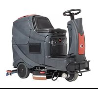
- TABLE OF CONTENTS
- INTRODUCTION....1
- SAFETY 2
- MACHINE DESCRIPTION....4
- OPERATING GUIDE 9
- MAINTENANCE....16
- TROUBLE SHOOTING 20
- SCRAPPING 22
- INTRODUCTION
- NOTE
- MANUAL CONTENT AND PURPOSE
- HOW TO KEEP THIS MANUAL
- DECLARATION OF CONFORMITY
- ACCESSORIES AND MAINTENANCE
- CHANGES AND IMPROVEMENTS
- SCOPE OF APPLICATION
- MACHINE IDENTIFICATION DATA
- TRANSPORT AND UNPACKING
- SAFETY
- SYMBOLS THAT APPEAR ON THEINSTRUCTION FOR USE MANUAL
- DANGER!
- WARNING!
- CAUTION!
- CONSULTATION
- GENERAL SAFETY INSTRUCTION
- MACHINE DESCRIPTION MACHINE STRUCTURE (as shown in Figure 1)
- MACHINE DESCRIPTION CONTROL PANEL (as shown in Figure 2)
- LED SCREEN DISPLAY INFORMATION
- DISPLAY WINDOW OF CHARGER INDICATION LIGHT (as shown in Figure 2)
- CIRCUIT DIAGRAM
- OPERATING GUIDE
- INSTALLING AND SETTING OF NEW MACHINE BATTERY
- The machine can be operated in one of following battery modes: A) WET or GEL/AGM batteries are already installed and ready to be used
- B) Without Batteries
- BATTERY INSTALLATION AND BATTERY TYPE SETTING (WET OR GEL/ AGM)
- Machine setting
- USER MANUAL
- ENGLISH
- Battery Installation
- Battery Type Dip-Switches
- EMERGENCY BRAKING
- BRUSH/PAD INSTALLATION AND UNINSTALLATION
- CAUTION
- SOLUTION TANK FILLING
- Drive motor inspection
- MACHINE START AND STOP
- Starting the machine
- Stopping the machine
- MACHINE OPERATION (SCRUBBING AND DRYING)
- Battery charging during the work
- TANK EMPTYING
- Recovery water tank emptying
- Solution/clean water tank emptying
- AFTER USING THE MACHINE
- MACHINE LONG INACTIVITY
- USING FOR THE FIRST TIME
- MAINTENANCE
- SCHEDULED MAINTENANCE TABLE
- BATTERY CHARGING
- The preparation steps to charge the batteries
- Use on-board charger for battery charging
- BRUSH/PAD CLEANING
- SOLUTION FILTER CLEANING
- SQUEEGEE CLEANING
- SQUEEGEE BLADE CHECK AND REPLACEMENT
- TANK AND VACUUM GRID WITH FLOAT CLEANING, AND COVER GASKET CHECK
- FUSE CHECK/REPLACEMENT
- ACCESSORIES/OPTIONS
- SCRAPPING
- TABLE DES MATIÈRES
- INTRODUCTION....23
- SÉCURITÉ 24
- DESCRIPTION DE LA MACHINE....26
- DÉPANNAGE 42
- RECYCLAGE 44
- REMARQUE
- COMMENT GARDER CE MANUEL
- DÉCLARATION DE CONFORMITÉ
- FREINAGE D'URGENCE
- REMLISSAGE DU RÉSERVOIR DE LA SOLUTION
- Arrêt de la machine
- UTILISATION POUR LA PREMIÈRE FOIS
- VÉRIFICATION ET REMPLACEMENT DE LA LAMELLE DE L'EMBOUCHURE
- VÉRIFICATION / REMPLACEMENT DU FUSIBLE
- FRENO DE EMERGENCIA
- Parar la máquina
- PRIMER USO
- Batterien einsetzen
- HINWEIS
- ERSTGEBRAUCH
- ANMERKUNG
- PROBLEEMOPLOSSING 108
- SLOOP 110
- INLEIDING
- OPMERKING
- WERKINGSGIDS
- WAARSCHUWING!
- NOODSITUATIE REMMEN
- VULLEN VAN OPLOSSINGSTANK
- Oplossing/schoonwater tank leegmaken
- GEBRUIK VOOR DE EERSTE KEER
- CONTROLE / VERVANGING VAN DE ZEKERING
- FRENATA DI EMERGENZA
- AVVIARE E FERMARE LA MACCHINA
- Avviare la macchina
- Fermare la macchina
- PRIMO UTILIZZO DELLA MACCHINA
- SIKKERHET 134
- MASKINBESKRIVELSE 136
- BRUKERVEILEDNING....141
- VEDLIKEHOLD....148
- FEILS∅ KING....152
- DESTRUERING 154
- INNLEDNING
- MERK
- TILBEH∅R OG VEDLIKEHOLD
- TRANSPORT OG UTPAKKING
- BRUKERVEILEDNING
- ADVARSEL!
- N∅ DBREMS
- Stoppe maskinen
- Batterilading
- F∅RSTEGANGS BRUK
- SJEKKE/SKIFTE SIKRINGER
- INNEHÅLLSFÖRTECKNING
- INLEDNING....148
- SÄKERHET 149
- MASKINBESKRIVNING 151
- BRUKSANVISNING....156
- UNDERHÅLL 162
- FELSÖKNING 166
- SKROTNING....168
- INLEDNING
- OBS!
- HANDBOKENS INNEHÅLL OCH SYFTE
- VÄTSKETANKFYLLNING
- Stoppa maskinen
- Batteriladdning under drift
- ANVÄNDNING FÖRSTA GÅNGEN
- SÄKRING KONTROLL/BYTE
- TROUBLESHOOTING....196
- BORTSKAFFELSE 198
- INTRODUKTION
- BEMÄRK
- MANUALENS INDHOLD OG FORMÅL
- BRUGSANVISNING
- Batteriinstallation
- MASKINENS BRUG (SKURING OG T∅RRING)
- BRUG F∅RSTE GANG
- SIKRINGSKONTROL/UDSKIFTNING
- MÄÄRÄAIKAISHUOLTOJEN AIKATAULU 214
- VIANETSINTÄ 218
- KIERRÄTYS 220
- JOHDANTO
- HUOMAUTUS
- KÄYTTÖOHJEET
- VAROITUS!
- Akun asennus
- HÄTÄPYSÄYTYS
- ENSIMMÄINEN KÄYTTÖKERTA
- VIANETSINTÄ
- Parar a máquina
- PRIMEIRA UTILIZAÇÃO
- ΣΗΜΕΙΩΣΗ
- Αξεσουαρ / Επιλογες
- ZAVIRANJE V SILI
- Zaustavitev naprave
- Polnjenje akumulatorja med delom
- PO UPORABI NAPRAVE
- PRVA UPORABA
- OPOMBA
- PREGLED/ZAMENJAVA VAROVALKE
- PROVOZNÍ PŘÍRUČKA 295
- ÚDRŽBA 302
- ŘEŠENÍ POTÍŽÍ 306
- LIKVIDACE 308
- ÚVOD
- POZNÁMKA
- INSTALACE A INSTALACE NOVÉ BATERIE PŘÍSTROJE
- VAROVÁNÍ!
- Vložení baterií
- NOUZOVÉ ZASTAVENÍ
- PLNĚNÍ NÁDRŽE S ČISTICÍM PROSTŘEDKEM
- Zastavení prístroje
- DLOUHÁ NEČINNOST PŘÍSTROJE
- PRVNÍ POUŽITÍ PŘÍSTROJE
- PŘÍSLUŠENSTVÍ/MOŽNOSTI
- SPOSÓB UŻYCIA
- OSTRZEŻENIE!
- NAPEŁNIANIE ZBIORNIKA NA ROZTWÓR
- PIERWSZE UŻYCIE
- INFORMACJA
- KONTROLA I WYMIANA BEZPIECZENIKÓW
- VÉSZFÉKEZŐ
- FIGYELEM!
- A gép leállítása
- HASZNÁLAT AZ ELSŐ ALKALOMMAL
- MEGJEGYZÉS
- BIZTOSÍTÉK ELLENÓRZÉSE/CSERÉJE
- INFORMATII AFIŞAJ ECRAN LED
- FRÂNAREA ÎN CAZ DE URGENTĂ
- UMPLEREA REZERVORULUI DE SOLUȚIE
- Oprirea maşinii
- PRIMA UTILIZARE
- ATENTIE
- VERIFICAREA/ÎNLOCUIREASIGURANTEI ELECTRICE
- ЗАБЕЛЕЖКА
- ПЪЛНЕНЕ НА РЕЗЕРВОАРА ЗА ПОЧИСТВАЩ РАЗТВОР
- ПЪРВО ИЗПОЛЗВАНЕ
- Аксесоари/Приставки
- Установка батареи
- Остановка машины
- Зарядка батарей
- PREVÁDZKOVÁ PRÍRUČKA 408
- ÚDRŽBA 414
- RIEŠENIE PROBLÉMOV......418
- LIKVIDÁCIA....420
- PRÍSLUŠENSTVO A ÚDRŽBA
- NÚ DZOVÉ ZABRZDENIE
- Naplnenie nádrže na roztok
- Zastavenie stroja
- AK JE STROJ DLHO NEČINNÝ
- POUŽITIE PRVÝKRÁT
- Batarya yerleştirme
- ACİL DURUM FRENLEMESİ
- SOLÜSYON TANKI DOLDURMA
- İLK KULLANIM
- ODRŽAVANJE 458
- RJEŠAVANJE PROBLEMA....462
- IZBACITI IZ UPORABE 464
- UVOD
- BILJEŠKA
- SADRŽAJ I SVRHA PRIRUČNIKA
- Instalacija baterije
- PRINUNDO KOČENJE
- PUNJENJE SPREMNIKA OTOPINE
- UPOZORENJE!
- UPORABA STROJA (ISPIRANJE I SUŠENJE)
- Otopina / pražnjenje čistog spremnika vode
- NAKON UPORABE STROJA
- KORIŠTENJE PRVI PUT
- PROVJERA / ZAMJENA OSIGURAČA
- PRIBOR / OPCIJE
Brand : NILFISK
Model : Viper AS530R
Category : Sweeper