
SolarMax 2500 - Pump UBBINK - Free user manual and instructions
Find the device manual for free SolarMax 2500 UBBINK in PDF.
| Product Type | Solar pump for garden fountain |
| Brand | Ubbink |
| Model | SolarMax 2500 Accu |
| Article Number | 13511183 |
| Maximum Flow Rate (Qmax) | 2480 l/h |
| Maximum Delivery Head (Hmax) | 2.1 m |
| Power Supply | Solar panel 35 W, 18 V DC; battery 12 V / 12 Ah (lead-gel AGM) |
| Pump Operating Voltage | 18 V DC |
| Pump Operating Current | 900 mA |
| Pump Protection Rating | IP68 |
| Solar Module Protection Rating | IP65 |
| Battery Pack Protection Rating | IP44 |
| Pump Operating Temperature | +5 °C to +40 °C |
| Solar Module Operating Temperature | -30 °C to +75 °C |
| Pump Connection Cable Length | 5 m |
| Battery Dimensions (L x H x W) | 152.4 x 96.5 x 99.1 mm |
| Main Functions | Solar operation with battery storage, timer (continuous or 10 min/h), 6 V output for accessories, dry-run protection, deep discharge protection |
| Maintenance and Cleaning | Clean the solar module with a microfiber cloth and glass cleaner; disassemble the pump to clean the rotor and ceramic shaft |
| Safety | Do not run dry; do not use in salt water; protect from frost; store battery charged in winter |
| Spare Parts and Repairability | Replaceable battery (lead 12 V / 12 Ah, flat connectors 4.8 mm); rotor and seals accessible after disassembly |
| Warranty | 2 years parts and labor (upon presentation of purchase receipt) |
Frequently Asked Questions - SolarMax 2500 UBBINK
User questions about SolarMax 2500 UBBINK
0 question about this device. Answer the ones you know or ask your own.
Ask a new question about this device
Download the instructions for your Pump in PDF format for free! Find your manual SolarMax 2500 - UBBINK and take your electronic device back in hand. On this page are published all the documents necessary for the use of your device. SolarMax 2500 by UBBINK.
USER MANUAL SolarMax 2500 UBBINK
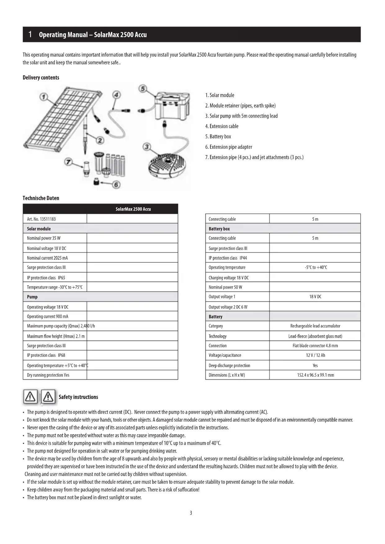
This operating manual contains important information that will help you install your SolarMax 2500 Accu fountain pump. Please read the operating manual carefully before installing the solar unit and keep the manual somewhere safe..
Delivery contents
- Solar module
- Module retainer (pipes, earth spike)
- Solar pump with 5m connecting lead
- Extension cable
- Battery box
- Extension pipe adapter
- Extension pipe (4 pcs.) and jet attachments (3 pcs.)
Technische Daten
| SolarMax 2500 Accu | |
| Art. No. 13511183 | |
| Solar module | |
| Nominal power 35 W | |
| Nominal voltage 18 V DC | |
| Nominal current 2025 mA | |
| Surge protection class III | |
| IP protection class IP65 | |
| Temperature range -30°C to +75°C | |
| Pump | |
| Operating voltage 18 V DC | |
| Operating current 900 mA | |
| Maximum pump capacity (Qmax) 2,480 l/h | |
| Maximum flow height (Hmax) 2.1 m | |
| Surge protection class III | |
| IP protection class IP68 | |
| Operating temperature +5°C to +40°C | |
| Dry running protection Yes | |
| Connecting cable | 5 m |
| Battery box | |
| Connecting cable | 5 m |
| Surge protection class III | |
| IP protection class IP44 | |
| Operating temperature | -5°C to +40°C |
| Charging voltage 18 V DC | |
| Nominal power 50 W | |
| Output voltage 1 | 18 V DC |
| Output voltage 2 DC 6 W | |
| Battery | |
| Category | Rechargeable lead accumulator |
| Technology | Lead-fleece (absorbent glass mat) |
| Connection | Flat blade connector 4.8 mm |
| Voltage/capacitance | 12 V / 12 Ah |
| Deep discharge protection | Yes |
| Dimensions (L x H x W) | 152.4 x 96.5 x 99.1 mm |
Safety instructions
- The pump is designed to operate with direct current (DC). Never connect the pump to a power supply with alternating current (AC).
- Do not knock the solar module with your hands, tools or other objects. A damaged solar module cannot be repaired and must be disposed of in an environmentally compatible manner.
- Never open the casing of the device or any of its associated parts unless explicitly indicated in the instructions.
- The pump must not be operated without water as this may cause irreparable damage.
- This device is suitable for pumping water with a minimum temperature of 10^ up to a maximum of 40^ .
- The pump not designed for operation in salt water or for pumping drinking water.
- The device may be used by children from the age of 8 upwards and also by people with physical, sensory or mental disabilities or lacking suitable knowledge and experience, provided they are supervised or have been instructed in the use of the device and understand the resulting hazards. Children must not be allowed to play with the device. Cleaning and user maintenance must not be carried out by children without supervision.
- If the solar module is set up without the module retainer, care must be taken to ensure adequate stability to prevent damage to the solar module.
- Keep children away from the packaging material and small parts. There is a risk of suffocation!
- The battery box must not be placed in direct sunlight or water.
1 Operating Manual – SolarMax 2500 Accu

Intended use
This product is designed exclusively for private use in small garden ponds. Direct sunlight is necessary to operate the pump. The battery is charged by direct sunlight. The pump is switched on when the battery voltage is in the operational range. In darkness, the pump is supplied by the battery for up to several hours, depending on the charge level. The pumping capacity can be altered via a potentiometer.
Electronic circuitry protects the battery from deep discharging, overcharging and short circuits.
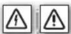
Caution! The plug connectors are protected from inverse polarity, so do not use force when connecting.
natural_image
Technical illustration of two mechanical components with threaded ends and shafts, showing alignment (no text or symbols)
lllation and commissioning
- Completely unroll the pump connecting cable.
- Screw the adapter for the extension pipe on to the pump outlet.
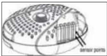
- Connect the appropriate number of extension pipes and attach the selected fountain jet. Attach the extension pipe and pipe adapter to the pump.
Vulkan: Make sure the spray head is not positioned too far above the water surface to maximise the height of the Vulkan fountain.

Water bell: The jet attachment should be placed well above the water surface. The size of the water bell can be adjusted by pressing down or lifting up the top part of the jet. The larger the gap for the water outlet, the smaller the water bell.

Bubbler jet: Make sure that the six deflector openings of the spray head are always under wa.

- Place the pump in the pond. Avoid a position directly on the bottom of the pond, because here the pump will suck in a lot of dirt and become quickly soiled.
- Put together the solar module retainer (pipes and earth spike) and then attach it to the back of the module.
- Connect the battery box plug to the solar module and tighten the retaining ring.
1 Operating Manual – SolarMax 2500 Accu
- Now connect the pump plug to the "OUTPUT 1 DC 18V" socket on the battery box.
- Turn the "SYSTEM ON/OFF" switch to "ON". The "SYSTEM" LED indicator lights up GREEN when the battery is charged and the pump can be switched on.
Note: the "SYSTEM" LED indicator is a dual-colour LED. If the display lights up RED then the pump is not working, because the residual charge is insufficient or the battery is being charged for the first time. The battery is charged after less than one day of sunshine. During charging phase, the "CHARGING" LED indicator shows YELLOW, regardless of whether the system is switched on or off. The charging process ends automatically once the battery has been charged to its maximum capacity. The charging of the battery always has priority over operating the pump.
- Activate the output jack 1 (OUTPUT 1) by pressing the ON/OFF button. If the output is switched on (ON) the LED indicator shows GREEN and the pump starts working. To stop the pump, switch off the output jack 1 by pressing the ON/OFF button.
-
The pump connected to the output jack 1 can be operated either in continuous mode or interval mode with the "TIMER ON/OFF" button.
-
TIMER OFF continuous mode, i.e. interval mode is deactivated and the pump runs continuously. This mode is only available when the SYSTEM LED indicator is showing green.
-
TIMER ON interval mode, i.e. the pump operates for 10 minutes per hour. This mode is useful for saving battery capacity, e.g. on cloudy days.
-
Output jack 2 (OUTPUT 2) provides of 6 volt DC supply for optional ancillary devices, for example, LED lighting. This jack does not have a timer function.
- Place the solar module in a sunny, shadow-free place.
- Ensure that the solar pump is always fully submerged in the water.
- The SolarMax 2500 Accu fountain set is now ready for operation.


Note
The pump has a built-in dry running protection function. Two sensor points are provided on one side of the pump body (not visible from the outside). If one or both of the sensor points is not under the water, the pump will stop working.


and maintenance
Solar module
Dust, dirt and leaf deposits can build up on the solar module. You can remove these with a microfibre cloth and glass cleaner.
Solar pump
Should the pump start to lose pumping capacity or after a period of time stop working, then please clean the pump as follows.
1) Disconnect the pump cable from the solar module.
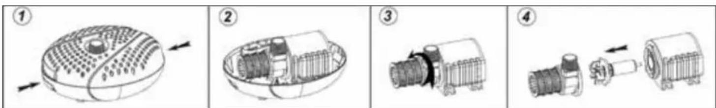
2) Unlock the top and bottom parts of the pump housing by pressing the clasps on the two opposite sides of the housing and then lift off the top part of the housing (see Figs. 1 and 2)
3) Take out the pump and open the rotor cover by turning it anticlockwise (see Fig. 3)
4) Pull out the rotor from the rotor bay (see Fig. 4)
6) Clean and wash the individual components.
7) Reassemble the pump in reverse order
Caution! During cleaning, please be careful not to damage the ceramic shaft. It can be easily broken.
Protect the pump and battery box from frost!
The pump should not be operated during the cold winter months. Clean the pump with warm water and store the whole system in a frost-free place. The battery box should ideally be stored in a fully charged state.
1 Operating Manual – SolarMax 2500 Accu
Replacing the battery
- Remove the 6 screws on the bottom of the battery box cover and take off the cover.
- Pull off the red or brown cable clamp on the positive battery terminal (+) and then the blue cable clamp on the negative battery terminal (-).
- Take out the old battery and insert the new battery.
- Attach the blue cable clamp on the negative battery terminal (-) and then the red or brown cable clamp on the positive battery terminal (+).
- The battery box is now ready for operation again.
TROUBLESHOOTING
| Problem Possible cause Remedy | ||
| The pump is not running | The solar module is not connected | Check the electrical connection between the battery box and the solar module. |
| The system switch is on “OFF” Turn the system switch to “ON” | ||
| The timer switch is on “ON”. Turn the timer switch to “OFF” | ||
| The dry running protection has activated Make sure the pump is fully submerged in water. | ||
| The battery is worn out Replace the battery | ||
| The impeller is stuck | Clean the pump as described under “Cleaning and maintenance” | |
| The system indicator LED is on RED | There is not enough sunshine to charge the battery, | wait for the sun to shine so that the battery can recharge |
| The pump is running but no water is coming out | The pump outlet or fountain jet is blocked | Clean the pump outlet, riser pipes and fountain jet. |

Warranty
We offer a warranty of two years on workmanship and materials from the date of purchase. To make a claim on the warranty, the original sales receipt must be enclosed. Warranty repairs may only be carried out by an authorised customer service provider. This warranty does not cover: ordinary wear and tear, alterations, reworking, damage due to negligence, third parties and applications for which the product has not been designed, partially or completely disassembled products..
Environmental protection
 | 1. Product:Old electrical equipment should not be disposed of with the household waste. Before disposing of your old equipment at your local recycling centre, remove the batteries and dispose of them separately from the product! Further information can be obtained from your equipment dealer or waste disposal company. |
 | 2. Product:End-consumers are legally required to return used batteries under the Battery Directive! You can hand in your used batteries free of charge at your local municipal collection points or anywhere where batteries are sold. Disposal via the household waste is prohibited!! |
Conformity declaration
The undersigned company UBBINK GARDEN BV declares on its own responsibility that the device SolarMax 2500 Accu satisfies the requirements of the European Directive 2014/30/EU (Electromagnetic Compatibility). The following harmonised standards were applied:
EN 61000-6-3:2007+A1:2011
EN 61000-3-2:2014
EN 61000-3-3:2013
EN 61000-6-1:2007
natural_image
Technical line drawing of two mechanical components with threaded ends and shafts (no text or symbols)


Pflege und Wartung
Solarmodul
natural_image
Technical illustration of two mechanical components with threaded ends and shafts (no text or symbols)

erhoud en service
Zonnepaneel
natural_image
Technical line drawing of two mechanical components with threaded ends and shafts (no text or symbols)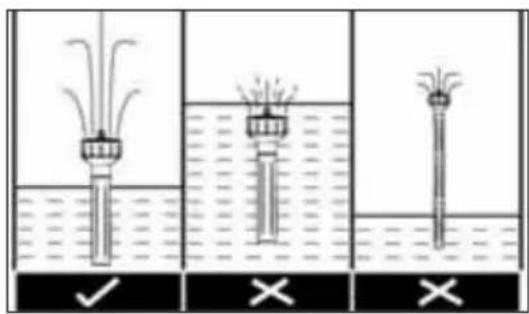


tien et maintenance
Module solaire
Datos técnicos
natural_image
Technical line drawing of two mechanical components with threaded ends and shafts (no text or symbols)Módulo solar
natural_image
Technical illustration of two mechanical components with threaded ends and shafts, showing alignment (no text or symbols)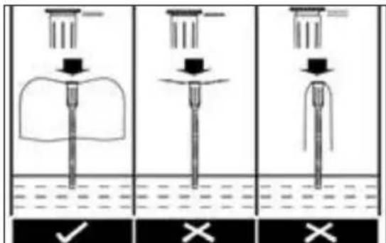

ia e manutenzione
Modulo solare
natural_image
Technical illustration of two mechanical components with threaded ends and shafts (no text or symbols)

do e manutenção
Módulo solar
natural_image
Technical illustration of two mechanical components with threaded ends and shafts, showing alignment (no text or symbols)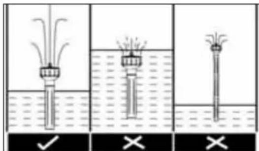

τίδα και συντήρηση
Ηλιακό πάνελ
natural_image
Technical line drawing of two mechanical components with threaded ends and shafts (no text or symbols)

og vedligeholdelse
Solarmodul
natural_image
Technical line drawing of two mechanical components with threaded ends and shafts (no text or symbols)

el och underhåll
Solcellsmodul
- Solcellemodul
- Modulholder (rør, jordspyd)
- Solcellepumpe med 5 m tilkoblingskabel
- Skjøtekabel
- Batteriboks
- Adapter for forlengelsesrør
- Forlengelsesrør (4 stk.) og dysehoder (3 stk.)
Tekniske data
| SolarMax 2500 Accu | |
| Artikkelnr. 13511183 | |
| Solcellemodul | |
| Nominell spenning 35 W | |
| Nominell spenning DC 18 V | |
| Nominell strøm 2025 mA | |
| Kapslingsklasse III | |
| Beskyttelsestype IP65 | |
| Temperaturområde -30 °C til +75 °C | |
| pumpe | |
| Driftsspenning DC 18 V | |
| Driftsstrøm 900 mA | |
| Maks. vannmengde (Qmax) 2 480 l/time | |
| Maks. vannføringshøyde (Hmax) 2,1 m | |
| Kapslingsklasse III | |
| Beskyttelsestype IP68 | |
| Driftstemperatur +5 °C til +40 °C | |
| Tørrgangsbeskyttelse ja | |
| Tilkoblingskabel 5 m | |
| Batteriboks | |
| Tilkoblingskabel 5 m | |
| Kapslingsklasse III | |
| Beskyttelsestype IP44 | |
| Driftstemperatur | -5 °C til +40 °C |
| Ladespenning | DC 18 V |
| Nominell spenning 50 W | |
| Utgangsspenning 1 | DC 18 V |
| Utgangsspenning 2 | DC 6 W |
| Akkumulator | |
| Kategori | Blyakkumulator, gjenoppladbar |
| Teknologi | Blyfleece (AGM) |
| Tilkobling | Europlugg 4,8 mm |
| Spenning/kapasitet | 12 V / 12 Ah |
| Utladingsbeskyttelse | Ja |
| Dimensjoner (L x H x B) | 152,4 x 96,5 x 99,1 mm |

natural_image
Technical line drawing of two mechanical components with threaded ends and shafts (no text or symbols)
- Plasser pumpen i dammen. Unngå en plassering direkte på dambunnen, ellers vil pumpen suge opp ekstra mye smuss og den dermed raskt blir skitten.
- Sett modulholderen til solcellemodulen (rør og jordspyd) sammen, og fest dette på baksiden av solcellemodulen.
- Koble pluggen til batteriboksen til solcellemodulen, og skru fast unionringen.
- Bruksanvisning for SolarMax 2500 Accu
- Nå kobler du pluggen til pumpen sammen med bøssingen „OUTPUT 1 DC 18V“ på batteriboksen.
- Sett bryteren „SYSTEM ON/OFF“ på „ON“. LED-lampen „SYSTEM“ lyser GRÖNT när batteriet er oppladet og pumpen kan innkobles.
Merknad: LED-lampen „SYSTEM“ har to farger. Hvis lampen lyser R∅DT, arbeider ikke pumpen, fordi batteriet ikke er nok oppladet eller lades for første gang. Men etter mindre enn én dag med solskinn er batteriet oppladet. Under lading lyser LED-lampen „CHARGING“ GULT, uavhengig av om systemet er slått på eller av. Ladeprosessen avsluttes automatisk när batteriet er oppladet til maksimal ladekapasitet. Batteriet må alltid lades för pumpen drives.

og vedlikeholdl
Solcellemodul
natural_image
Technical line drawing of two mechanical components with threaded ends and shafts (no text or symbols)
nus ja käyttöönotto

ja huolto
Aurinkopaneeli
natural_image
Technical illustration of two mechanical components with threaded ends and shafts, showing alignment (no text or symbols)natural_image
Technical line drawing of two mechanical components with threaded ends and shafts (no text or symbols)

- solarni modul
- držač modula (cijevi, šiljak za zemlju)
- solarna pumpa s priključnim vodom duljine 5 m
- produžni kabel
- kutija s punjivom baterijom
- adapter za produžnu cijev
- produžne cijevi (4 kom.) i nastavci mlaznica (3 kom.)
Tehnički podatci
| SolarMax 2500 Accu | |
| Br. artikla 13511183 | |
| Solarni modul | |
| Nazivna snaga 35 W | |
| Nazivni napon DC 18 V | |
| Nazivna struja 2025 mA | |
| Razred zaštite III | |
| Vrsta zaštite IP65 | |
| Temperaturno područje od -30 °C do -75 °C | |
| Pumpa | |
| Radni napon DC 18 V | |
| Radna struja 900 mA | |
| Maks. količina prijenosa (Qmax) 2.480 l/h | |
| Maks. visina prijenosa (Hmax) 2.1 m | |
| Razred zaštite III | |
| Vrsta zaštite IP68 | |
| Radna temperatura od +5 °C do +40 °C | |
| Zaštita od rada na suho da | |
| Priključni kabel | 5 m |
| Kutija s punjivom baterijom | |
| Priključni kabel | 5 m |
| Razred zaštite III | |
| Vrsta zaštite IP44 | |
| Radna temperatura | od -5 °C do +40 °C |
| Napon punjenja | DC 18 V |
| Nazivna snaga 50 W | |
| Izlazni napon 1 | DC 18 V |
| Izlazni napon 2 DC 6 W | |
| Punjiva baterija | |
| Kategorija | Olovna baterija, punjiva |
| Tehnologija | olovo, netkana vlakna (AGM) |
| Priključak | Plosnati utikač 4,8 mm |
| Napon/kapacitet | 12 V / 12 Ah |
| Zaštita od dubokog pražnjenja | Da |
| Dimenzije (D x V x Š) | 152,4 x 96,5 x 99,1 mm |

Sigurnosne upute
- Pumpa je konstruirana za pogon s istosmjernom strujom (DC). Pumpu nemojte nikako spajati na opskrbu mrežnom izmjeničnom strujom (AC).
- Ne udarajte rukama, alatima ili drugim predmetima o solarni modul. Oštećeni solarni modul ne može se više popraviti i treba ga ekološki prihvatljivo zbrinuti.
- Nikada ne otvarajte kućište uređaja ili njegove pripadajuće dijelove ako to nije izričito zatraženo u uputama za uporabu.
- Pumpa se nikada ne smije upotrebljavati bez vode jer to može dovesti do nepopravljivih šteta.
- Ovaj je uređaj namijenjen za ispumpavanje vode s temperaturom od min. 5 °C do maks. 40 °C.
- Pumpa nije namijenjena za uporabu u slanoj vodi i za transport pitke vode.
- Ovim se uređajem smiju koristiti djeca starija od 8 godina i osobe smanjenih tjelesnih, osjetilnih ili mentalnih sposobnosti ili osobe kojima nedostaje znanja i iskustva ako su pod nadzorom ili su upućene u sigurnu uporabu ovog uređaja i ako razumiju opasnosti koje iz nje proizlaze. Djeca se ne smiju igrati ovim uređajem. Djeca ne smiju bez nadzora obavljati čišćenje i održavanje namijenjeno za korisnika.
- Ako se solarni modul postavlja bez držača modula, trebate pripaziti na dovoljnu stabilnost kako biste izbjegli oštećenja na solarnom modulu.
- Djecu držite podalje od sitnih dijelova i materijala pakiranja. Postoji opasnost od gušenja!
- Kutiju s punjivom baterijom ne postavljajte izravno na sunce ili u vodu.
Unamjenska uporaba
natural_image
Technical line drawing of two mechanical components with threaded ends and shafts (no text or symbols)- Stavite pumpu u jezerce. Izbjegavajte lokaciju izravno na dnu vrtnog jezerca jer bi tu pumpa usisavala posebno puno prljavštine i brzo se začepila.
- Sastavite držač solarnog modula (cijevi i šiljak za zemlju) i pričvrstite ih na stražnju stranu solarnog modula.
- Spojite utikač kutije s punjivom baterijom sa solarnim modulom i čvrsto zavijte spojnu maticu.
HR Upute za uporabu SolarMax 2500 Accu
- Sada spojite utikač pumpe s utičnicom „OUTPUT 1 DC 18V” na kutiji s punjivom baterijom.
- Okrenite prekidač „SYSTEM ON/OFF“ na „ON“. LED prikaz „SYSTEM“ svijetli ZELENO kada je punjiva baterija napunjena, a pumpa se može uključiti.

i održavanje
Solarni modul
Na solarnom modulu mogu se nataložiti naslage prašine, prljavštine i lišća. Možete ih očistiti krpom od mikrovlakana i sredstvom za čišćenje stakla.
Solarna pumpa
1) Odvojite kabel pumpe od solarnog modula.
2) Otključajte gornji i donji dio pumpe pritiskom kopči s obje suprotne strane kućišta pumpe, a zatim podignite gornji dio kućišta pumpe (vidi slike 1 i 2).
3) Izvadite pumpu i otvorite poklopac rotora okretanjem suprotno od smjera kazaljki na satu (vidi sliku 3).
4) Izvadite rotor iz otvora za rotor (vidi sliku 4).
6) Očistite i operite pojedinačne dijelove.
7) Montirajte pumpu obrnutim redoslijedom.
Pozor! Tijekom radova čišćenja budite oprezni s keramičkim vratilom jer može lako puknuti.
Zaštitite pumpu i kutiju s punjivom baterijom od mraza!
natural_image
Technical illustration of two mechanical components with threaded ends and shafts, showing alignment (no text or symbols)
natural_image
Technical line drawing of two mechanical components with threaded ends and shafts (no text or symbols)
natural_image
Technical illustration of two mechanical components with threaded ends and shafts (no text or symbols)
aža in zagon

in vzdrževanje
Solarni modul
natural_image
Technical illustration of two mechanical components with threaded ends and shafts (no text or symbols)

is és karbantartás
Napelem modul
natural_image
Technical line drawing of two mechanical components with threaded ends and shafts (no text or symbols)

lus ja korrashoid
Päikesemoodul
Tehniskie dati
natural_image
Technical illustration of two mechanical components with threaded ends and shafts, showing alignment (no text or symbols)

natural_image
Diagram of a circular device with internal grid pattern and directional arrows (no text or symbols)
natural_image
Technical line drawing of a mechanical component inside a bowl (no text or symbols)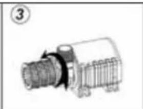
natural_image
Technical line drawing of a mechanical component with threaded shaft and flange (no text or symbols)
natural_image
Diagram showing three mechanical components: a cylindrical motor, a gear assembly, and a motor with an arrow indicating motion (no text or labels)natural_image
Technical illustration of two mechanical components with threaded ends and shafts (no text or symbols)

natural_image
Technical line drawing of two mechanical components with threaded ends and shafts (no text or symbols)

и и поддръжка
Соларен модул
natural_image
Technical illustration of two mechanical components with threaded ends and shafts, showing alignment (no text or symbols)
Modul solar
natural_image
Technical line drawing of two mechanical components with threaded ends and shafts (no text or symbols)
taj ve çalıştırma

n ve denetim
Solar modülü
(1)
natural_image
Technical line drawing of two mechanical components with threaded ends and grooves (no text or symbols)لی فضخَلَهُمْ لَأَكْتَمْ لِهِيْتَالاتِ طَنْ إِقِكَزُمَا مِيْف مَتَدِ يَذِنا نَ اکملَا وَهَا اَدَهِن لَا، ٌٌ کَر
قطساوب
: ظطوحلم
1( لصفا
(F) Outside Living Industries France
adv@outsideliving.com
(NL) Outside Living Industries Nederland
Postbus
15
NL - 1800 AA Alkmaar
Berenkoog
87
NL - 1822 BN Alkmaar
Tel. verkoop: 0031 - (0)72-5 671 661
Tel.: 0031 - (0)72-5 671 671
Fax: 0031 - (0)72 5 671 673
E-Mail:
info@outsideliving.com
(B) / (L) Outside Living Industries BeLux BVM
Wondelgemkaai
10
B - 9000 Gent
- Safety instructions
- Operating Manual – SolarMax 2500 Accu
- Intended use
- lllation and commissioning
- Note
- and maintenance
- Solar module
- Solar pump
- Caution! During cleaning, please be careful not to damage the ceramic shaft. It can be easily broken.
- Protect the pump and battery box from frost!
- Replacing the battery
- Warranty
- Conformity declaration
- Pflege und Wartung
- Solarmodul
- erhoud en service
- Zonnepaneel
- tien et maintenance
- Module solaire
- Módulo solar
- ia e manutenzione
- Modulo solare
- do e manutenção
- τίδα και συντήρηση
- Ηλιακό πάνελ
- og vedligeholdelse
- el och underhåll
- Solcellsmodul
- - Bruksanvisning for SolarMax 2500 Accu
- og vedlikeholdl
- Solcellemodul
- nus ja käyttöönotto
- ja huolto
- Aurinkopaneeli
- Sigurnosne upute
- Unamjenska uporaba
- HR Upute za uporabu SolarMax 2500 Accu
- i održavanje
- Solarni modul
- Solarna pumpa
- Pozor! Tijekom radova čišćenja budite oprezni s keramičkim vratilom jer može lako puknuti.
- Zaštitite pumpu i kutiju s punjivom baterijom od mraza!
- aža in zagon
- in vzdrževanje
- is és karbantartás
- Napelem modul
- lus ja korrashoid
- Päikesemoodul
- и и поддръжка
- Соларен модул
- Modul solar
- taj ve çalıştırma
- n ve denetim
- Solar modülü
- Outside Living Industries France
- (NL) Outside Living Industries Nederland
- / (L) Outside Living Industries BeLux BVM
Brand : UBBINK
Model : SolarMax 2500
Category : Pump