DP16VLS - Drill SCHEPPACH - Free user manual and instructions
Find the device manual for free DP16VLS SCHEPPACH in PDF.
| Brand | Scheppach |
| Model | DP16VLS |
| Product type | Drill press |
| Supply voltage | 230-240 V~ / 50 Hz |
| Rated power | 350 W (S1) / 500 W (S6 40%) |
| Motor speed | 1450 min⁻¹ |
| Spindle speed | 5 speeds: 600 / 900 / 1300 / 1800 / 2650 min⁻¹ |
| Chuck capacity | 1.5 – 13 mm |
| Spindle taper | B16 |
| Table dimensions | 160 x 160 mm |
| Table tilt | 45°/0°/45° |
| Maximum drilling depth | 50 mm |
| Column diameter | 46 mm |
| Total height | 600 mm |
| Footprint (base) | 290 x 190 mm |
| Weight | 13.5 kg |
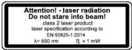
| Laser | Class II, 650 nm, < 1 mW |
| Sound pressure level (LpA) | 70.8 dB (uncertainty 3 dB) |
| Sound power level (LWA) | 83.8 dB (uncertainty 3 dB) |
| Vibration emission (ah) | 1.6 m/s² (uncertainty 1.5 m/s²) |
| Wear parts | Brushes, V-belt, battery, drill bit |
Frequently Asked Questions - DP16VLS SCHEPPACH
User questions about DP16VLS SCHEPPACH
0 question about this device. Answer the ones you know or ask your own.
Ask a new question about this device
Download the instructions for your Drill in PDF format for free! Find your manual DP16VLS - SCHEPPACH and take your electronic device back in hand. On this page are published all the documents necessary for the use of your device. DP16VLS by SCHEPPACH.
USER MANUAL DP16VLS SCHEPPACH
Günzburger Straße 69
D-89335 Ichenhausen
Verehrter Kunde,
Homepage: https://www.scheppach.com/de/service
Explanation of the symbols on the equipment
| Warning! Disregard results in a risk of death or injury, or damage to the tool! | |
| Before commissioning, read and observe the operating manual and safety instructions! | |
| Wear eye protection! | |
| Wear hearing protection! | |
| Wear breathing protection when generating dusk! | |
| Do not wear long hair uncovered. Use a hair net. | |
| Do not wear gloves. | |
| Important! Laser radiation | |
| The product complies with the applicable European directives. | |
| The product complies with the applicable Serbian directives. |
Table of contents: Page:
- Introduction 24
- Device description 24
- Scope of delivery 25
- Intended use 25
- Safety information.. 25
- Technical data 27
- Before starting the equipment 28
- Montage 28
- Operation 29
- Transport 31
- Cleaning and Servicing 31
- Storage 32
- Electrical connection 32
- Disposal and recycling 33
- Troubleshooting 34
- Declaration of conformity 349
1. Introduction
Manufacturer:
Scheppach GmbH
Günzburger Straße 69
D-89335 Ichenhausen
Dear Customer,
we hope your new tool brings you much enjoyment and success.
Note:
According to the applicable product liability laws, the manufacturer of the device does not assume liability for damages to the product or damages caused by the product that occurs due to:
- Improper handling,
Non-compliance of the operating instructions, - Repairs by third parties, not by authorized service technicians,
- Installation and replacement of non-original spare parts,
Application other than specified, - A breakdown of the electrical system that occurs due to the non-compliance of the electric regulations and VDE regulations 0100, DIN 570,813/ VDE0113.
We recommend:
Read through the complete text in the operating instructions before installing and commissioning the device.
The operating instructions are intended to help the user to become familiar with the machine and take advantage of its application possibilities in accordance with the recommendations.
The operating instructions contain important information on how to operate the machine safely, professionally and economically, how to avoid danger, costly repairs, reduce downtimes and how to increase reliability and service life of the machine.
In addition to the safety regulations in the operating instructions, you have to meet the applicable regulations that apply for the operation of the machine in your country.
Keep the operating instructions package with the machine at all times and store it in a plastic cover to protect it from dirt and moisture. Read the instruction manual each time before operating the machine and carefully follow its information.
The machine can only be operated by persons who were instructed concerning the operation of the machine and who are informed about the associated dangers. The minimum age requirement must be complied with.
In addition to the safety instructions contained in this operating manual and the specific regulations of your country, the technical rules generally accepted for the operation of machines of the same type must be observed.
We accept no liability for damage or accidents which arise due to non-observation of these instructions and the safety information.
2. Device description
- Base plate
- Pillar
- Drilling table
- Machine head
- Drill chuck
- Grips
- Drill chuck protection
- Depth stop
- Motor
- On-Off switch
- Belt protective hood
- Counternuts for belt tension
- Laser module
13.1 Laser on/off switch
13.2 Battery compartment cover - Vice
A Hexagonal screw
B 4 mm Allen key
C Vice fastening screws
D Drill chuck key
E Table locking
F Allen screws
G Nut fastening, depth stop
H Philips screw, chuck guard
I Hole housing, depth stop
J Nut, depth stop
K Pointer, depth stop
L Groove
M Spring cap
N Inner nut
O Outer nut
P Hub
S Table locking
T Laser set screw
U Laser countersunk screw
V Belt guard screw
W Laser locknut
3. Scope of delivery
- Base plate
- Pillar
- Drilling table
Machine head - Drill chuck
- Drill chuck key
- Drill chuck protection
Grips - Depth stop
4 mm Allen key - Accessory bag
- Laser module
- Operating manual
4. Intended use
The bench drill is designed for drilling in metal, wood, plastic and tiles.
Chuck clamping range: 1.5 - 13 mm.
The device is intended to be used by do-it-yourselfers. It was not designed for heavy commercial use. The tool is not to be used by persons under the age of 16. Children over the age of 16 may use the tool except under supervision. The manufacturer is not liable for damage caused by an improper use or incorrect operation of this device.
Please note that our equipment has not been designed for use in commercial, trade or industrial applications. Our warranty will be voided if the equipment is used in commercial, trade or industrial businesses or for equivalent purposes.
5. Safety information
General safety instructions for electric tools
WARNING! Read all safety instructions, information, illustrations and technical data for this electric tool. Failure to observe the following information and instructions can result in electric shock, fire and/or serious injuries.
Store all safety instructions and information for future reference.
The term "electric tool" used in the safety instructions refers to mains-powered electric tools (with a mains cable) or battery-powered electric tools (without a mains cable).
Workplace safety
a) Keep your work area clean and well-lit. Disorganised or unlit work areas can result in accidents.
b) Do not work with the electric tool in an explosive environment where flammable liquids, gases or dusts may be located. Electric tools produce sparks that may ignite dust or vapours.
c) Keep children and other people away while using the electric tool. Distractions may cause you to lose control of the electric tool.
Electrical safety
a) The electrical tool's connection plug must fit into the socket. The plug may not be modified in any way. Do not use an adaptor plug together with earthed electric tools. Unmodified plugs and suitable sockets reduce the risk of an electric shock.
b) Avoid body contact with earthed surfaces, such as pipes, heaters, ovens and refrigerators. There is an increased risk of electric shock if your body is earthed.
c) Keep electric tools away from rain and moisture. Water entering an electric tool increases the risk of an electric shock.
d) Do not use the cable for another purpose, for example, carrying or hanging the electric tool or pulling the plug out of the socket. Keep the cable away from heat, oil, sharp edges or moving device parts. Damaged or coiled cables increase the risk of an electric shock.
e) If you work with an electric tool outdoors, only use extension cables that are also suitable for outdoor use. Using an extension cable suitable for outdoor use reduces the risk of an electric shock.
f) If you cannot avoid using the electrical tool in a wet environment, use a fault-current circuit breaker. Using a fault-current circuit breaker reduces the risk of an electric shock.
Safety of personnel
a) Remain attentive, pay attention to what you are doing and be sensible when working with electric tools. Do not use an electric tool if you are tired or under the influence of drugs, alcohol or medication. A moment of carelessness when using electrical tools can result in serious injuries.
b) Wear personal protective equipment and always wear safety goggles. Protective equipment such as a dust mask, non-skid safety shoes, hard hat or hearing protection used for appropriate conditions will reduce personal injuries.
c) Avoid unintentional startup. Make sure that the electric tool is switched off before you connect it the power supply and/or battery, pick it up or carry it. Carrying power tools with your finger on the switch or energising power tools that have the switch on invites accidents.
d) Remove the setting tools or spanners before switching on the electric tool. A tool or spanner that is located in a rotating device part may result in injuries.
e) Avoid abnormal posture. Make sure that you have secure footing and always maintain your balance. This will allow you to better control the electric tool in unexpected situations.
f) Wear suitable clothing. Do not wear wide clothing or jewellery. Keep hair, clothing and gloves away from moving parts. Loose clothing, jewellery and long hair can be caught by moving parts.
g) If dust extraction and collection devices can be mounted, make sure that they are connected and used properly. Using a dust extraction unit can reduce hazards caused by dust.
h) Do not allow yourself to be lulled into a false sense of security and do not ignore the safety rules for electric tools, even when you have used them many times and have become familiar with them. Careless actions can result in serious injuries within a fraction of a second.
Using and handling the electric tool
a) Do not overload the device. Use the electric tool intended for your work. The suitable electric tool allows you to work better and more safely in the indicated power range.
b) Do not use an electric tool whose switch is defective. An electric tool that cannot be switched on or off is dangerous and must be repaired.
c) Remove the plug from the socket and/or take out a removable battery before setting the device, changing insertion tool parts or putting the electric tool away. These precautionary measures will prevent the electric tool from starting unintentionally.
d) Keep unused electric tools out of the reach of children. Do not let people use the electric tool who are not familiar with it or who have not read these instructions. Electric tools are dangerous if they are used by inexperienced people.
e) Maintain electric tools and tool attachments with care. Check whether moving parts function properly and do not get stuck and whether parts are broken or are damaged and thus adversely affect the electric tool function. Have damaged parts repaired before using the electric tool. Many accidents are caused by poorly maintained electric tools.
f) Always keep cutting tools sharp and clean. Carefully maintained cutting tools with sharp cutting edges seize up less often and are easier to guide.
g) Use electric tools, accessories, insertion tool, etc. according to these instructions. Take the working conditions and the activity to be carried out into consideration. Using electric tools for applications other than the intended uses can lead to dangerous situations.
h) Keep the handles and gripping surfaces dry, clean and free of oil and grease. Slippery handles and gripping surfaces prevent safe operation and control of the electrical tool in unforeseen situations.
Service
a) Only have your electric tool repaired by qualified specialists and only with original spare parts. This ensures that safety of the electric tool is maintained.
Safety instructions for drills
a) The drill must be secured. An incorrectly secured drill can move or topple and this can result in injuries.
b) The workpiece must be clamped or fastened to the workpiece support. Do not drill into workpieces that are too small to be securely clamped. Holding the workpiece by hand can lead to injuries.
c) Do not wear gloves. Gloves can be caught by rotating parts or drilling debris and thus cause injuries.
d) Keep your hands away from the drilling area whilst the electrical tool is running. Contact with rotating parts or drilling debris can cause injuries .
e) The drill must be turning before it makes contact with the workpiece. Otherwise, the drill bit can catch in the workpiece and this can result in an unexpected movement of the workpiece and cause injuries.
f) If the drill becomes jammed, stop pressing downwards and switch the electrical tool off. Investigate and rectify the cause of the jamming. Jamming can result in an unexpected movement of the workpiece and can result in serious injuries.
g) Avoid long pieces of drill swarf by interrupting the downward pressure at regular intervals. Sharp metal swarf can become tangled and lead to injuries.
h) Never remove drilling debris from the drilling area whilst the electrical tool is running. To remove swarf, move the drill away from the workpiece, switch off the electrical tool and wait until the drill has come to a standstill. Use an aid such as a brush or a hook to remove the swarf. Contact with rotating parts or drilling debris can cause injuries.
i) The permissible rotational speed for drill bits with a rated speed must be at least as high as the highest speed cited on the electrical tool. Accessories that rotate faster than permitted can break and fly off at high speed.
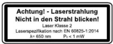
Attention: Laser radiation
Do not look into the beam
Laser class 2
Protect yourself and you environment from accidents using suitable precautionary measures!
- Do not look directly into the laser beam with unprotected eyes.
- Never look into the path of the beam.
- Never point the laser beam towards reflecting surfaces and persons or animals. Even a laser beam with a low output can cause damage to the eyes.
- Caution - methods other than those specified here can result in dangerous radiation exposure.
-
Never open the laser module. Unexpected exposure to the beam can occur.
-
The laser may not be replaced with a different type of laser.
- Repairs of the laser may only be carried out by the laser manufacturer or an authorised representative.
- Labelling and placement of warning stickers, see fig. 8 and 9.
WARNING! This electric tool generates an electromagnetic field during operation. This field can impair active or passive medical implants under certain conditions. In order to prevent the risk of serious or deadly injuries, we recommend that persons with medical implants consult with their physician and the manufacturer of the medical implant prior to operating the electric tool.
Residual risks
Even if you use this electric power tool in accordance with instructions, certain residual risks cannot be eliminated. The following hazards may arise in connection with the equipment's construction and layout:
- Lung damage if suitable dust protection mask is not worn.
- Hearing damage if suitable hearing protection is not worn.
- Damage to health resulting from hand/arm vibration if the device is used over an extended period of time or if it is not properly operated and maintained.
6. Technical data
| Nominal input voltage | 230-240 V~/50 Hz |
| Power rating | 350 W (S1) 500 W (S6 40%) |
| Motor speed 1450 min | -1 |
| Output speed | 600 min-1 900 min-1 1300 min-1 1800 min-1 2650 min-1 |
| Drill chuck mount B16 | |
| Drill chuck 1,5 - 13 mm | |
| Dimensions of drill table 160 x 160 mm | |
| Angle adjustment of table | 45°/0°/45° |
| Drill depth | 50 mm |
| Pillar diameter | 46 mm |
| Height | 600 mm |
| Base area 290 x 190 mm |
| Weight 13,5 kg |
| Laser class II |
| Wavelength of laser 650 nm |
| Laser output < 1 mW |
*S6 40% = Continuous periodic operation duty with a duty cycle of 40% (4,0 min based on a 10 minute period)
Noise and vibration values
The total noise values determined in accordance with EN 62841.
| Sound pressure level LpA | 70,8 dB |
| Uncertainty KpA | 3 dB |
| Sound power level LWA | 83,8 dB |
| Uncertainty KWA | 3 dB |
Wear hearing protection.
The effects of noise can cause a loss of hearing. Total vibration values (vector sum - three directions) determined in accordance with EN 62841.
Vibration emission value ah 1.6 m/s Uncertainty K 1.5 m/s2
The specified vibration value was established in accordance with a standardized testing method. It may change according to how the electric equipment is used and may exceed the specified value in exceptional circumstances.
The specified vibration value can be used to compare the equipment with other electric power tools.
The specified vibration value can be used for initial assessment of a harmful effect.
7. Before starting the equipment
- Open the packaging and remove the device carefully.
- Remove the packaging material as well as the packaging and transport bracing (if available).
- Check that the delivery is complete.
- Check the device and accessory parts for transport damage.
- If possible, store the packaging until the warranty period has expired.
ATTENTION
The device and packaging materials are not toys! Children must not be allowed to play with plastic bags, film and small parts! There is a risk of swallowing and suffocation!
8. Montage
Column and machine foot (Fig. 3)
- Set the machine foot (1) down on the ground or the workbench.
- Place the column (2) on the base plate so that the holes on the column (2) align with the holes on the base plate (1).
- Screw the hexagonal screws (A) to fasten the column into the base plate and tighten them using a hexagon spanner.
Table and pillar (Fig. 4)
- Slide the drilling table (3) onto the pillar (2). Position the table directly above the base plate.
- Install the table bolting (E) in the table unit from the left side and tighten it.
Machine head and pillar (Fig. 5)
- Place the machine head (4) onto the pillar (2).
- Put the spindle of the drilling machine with the table and the base plate in the cover and fasten the 2 Allen screws (F).
Drill chuck protection with depth stop (Fig. 6)
- Fit the chuck guard (7) on the spindle tube and tighten the Philips screw (H).
- Unfold the chuck guard (7).
- Remove the nut (G) from the depth stop rod (8).
- Guide the depth stop rod through the hole (I) on the machine head (4)
- Fasten the depth stop rod (8) with the nut (G) in the hole of the chuck guard (7).
- Turn the pointer on the depth stop rod (8) to the scale on the machine head (4).
The nuts (J) act to limit the depth.
Feed handles to the shaft hub (Fig. 7)
- Screw the feed handles (6) tightly into the threaded holes in the hub.
Installing the chuck (Fig. 8)
- Clean the conical hole in the chuck (5) and the spindle cone with a clean piece of fabric. Make sure there are no foreign particles sticking to the surfaces.
The slightest piece of dirt on any of these surfaces will prevent the chuck from seating properly. This will cause the drill bit to wobble". If tapered hole in the chuck is extremely dirty, use a cleaning solvent on the clean cloth.
- Push the chuck up on the spindle nose as far as it will go.
- Turn chuck sleeve clockwise (when viewed from above) and open jaws in chuck completely.
- Place a piece of wood on the machine table and lower the spindle onto the piece of wood. Press firmly to ensure that the food sits exactly.
Installing laser module (Fig. 15, 16)
Fasten the laser module (13) with the countersunk screw (U) onto the machine head (4) as shown in the figures.
Make sure the plastic pin on the laser module sits in the hole without thread.
Fastening radial drill press to supporting surface
For your own safety, screw connection on a workbench or similar is strongly recommended.
Warning:
All the necessary adjustments for the good working of your drill press have been done at the factory. Please do not modify them.
However, because of a normal wear and tear of your tool, some readjustments might be necessary.
9. Operation
Attention!
Always make sure the product is fully assembled before commissioning!
Warning:
If you are not familiar with this kind of machine, take advice from an experimented person. In any case you should have read and understood the safety and operational instruction before attempting to operate this product.
Pivoting the table (Fig. 10)
-
To bring the table (3) to the inclined position, release the table locking (S) and adjust the desired table angle.
-
Re-tighten the table locking.
Adjusting table height (Fig. 11)
- Loosen the table support lock handle (E).
- Adjust the table (3) to the desired height.
- Re-tighten the table locking (E).
- Note: It is better to lock the table to the column in a position so that the tip of the drill bit is just slightly above the top of the workpiece.
Choosing speed and tensioning belt (Fig. 12) Note! Pull power plug!
You can set different spindle speeds on your pillar drilling machine:
- Once you have switched off the device, you can open the belt guard (11). Loosen the screw (V) and open the belt guard (11). All adjustment options for the spindle speed are available in the machine's belt guard (11)
- Loosen the drive belt on the right side of the machine head by unfastening the locking nuts (12) on both sides. Pull the right side of the motor in the direction of the spindle to loosen the v-belt. Tighten the counternuts again (12).
- Attach the v-belt to the corresponding belt pulleys. The belt must always run straight.
- Loosen the counternuts (12) and press the right side of the engine back, in order to tension the V-belt again.
- Tighten the counternuts again (12). Belt should deflect approximately 13mm - 1 / 2 by thumb pressure at mid-point of belt between pulleys.
- Close the belt guard (11).
- If belt slips while drilling readjust belt tension.
Tip: Safety switch
If you wish to set the speed, you must open the belt guard (11). The device switches off immediately to avoid the risk of injuries.
Removing the chuck
Open jaws of chuck as wide as they go by turning chuck sleeve anticlockwise.
Carefully tap chuck with mallet in one hand while holding chuck in other hand to prevent dropping it when released from spindle nose.
Fitting tools to the drill chuck
Make sure that the power plug is removed from the socket-outlet before changing tools.
Only cylindrical tools with the stipulated maximum shaft diameter may be clamped in the drill chuck (5). Only use a tool that is sharp and free of defects.
Do not use tools whose shaft is damaged or which are deformed or flawed in any other way. Use only accessories and attachments that are specified in the operating instructions or have been approved by the manufacturer.
Using the drill chuck
Your drill is equipped with a gear-toothed drill chuck (5). In order to insert a drill bit, first fold the chuck guard (7) up, then insert the drill bit and tighten the chuck (5) with the chuck key (D) supplied.
Pull out the chuck key (D).
Ensure that the clamped tool is firmly seated.
Important!
Do not leave the chuck key in the clamp hole.
Doing so will cause the chuck key to be catapulted out, which could cause injury.
Depth scale method (Fig. 6)
Note: For this method, with the spindle in its upper position the tip of the drill bit must be just slightly above the top of the workpiece.
- Switch off the machine, lower the drill so far until the indicator points at the desired drilling depth of the depth scale.
- Turn the lower nut (J2) to the hole (I) stop.
- Lock the top nut (J1) against the bottom nut (J2).
- The chuck and the drill bit will now be stopped after traveling downward the distance selected on the depth scale.
Clamping the workpiece (Fig. 13, 14)
As a general rule, use a machine vice or another suitable clamping device to lock a workpiece into position.
Never hold the workpiece in place with your hand!
When drilling, the workpiece should be able to travel on the drill table (3) for self-centering purposes. Ensure that the workpiece cannot rotate. This is best achieved by placing the workpiece/machine vice on a sturdy block.
Important!
Sheetmetal parts must be clamped in to prevent them from being torn up. Properly set the height and angle of the drill table for each workpiece. There must be enough distance between the upper edge of the workpiece and tip of the drill bit.
Positioning table and workpiece (Fig. 14)
Always place a piece of back up material ('wood, plywood...) on the table undemeath the workpiece. This will prevent splitering or making a heavy burr on the underside of the workpieces as the drill bit breaks through. To keep the back up material from spinning out of control it must contact the left side of the column as illustrated.
Warning:
To prevent the workpiece or the backup material from being torn from your hand while drilling, position them to the left side of the column. If the workpiece or the backup material are not long enough to reach the column, clamp them to the table. Failure to do this could result in personal injury.
Note: For small pieces that cannot be clamped to the table, use a drill press vise.
The vice must be clamp or bolt to the table to avoid injury from spinning work and vise or tool breakage.
Mounting the machine vice on the drilling table
Fasten the machine vice using the screws, washers and nuts provided, as shown in Fig. 13.
Using the laser (Fig. 15, 16)
Replacing the battery:
Switch off the laser. Remove the battery compartment cover (13.2). Remove the batteries and replace with new batteries.
To switch on:
Move the ON/OFF switch (13.1) to the "l" position to switch on the laser.
Two laser lines are projected on the workpiece and intersect at the centre of the drill tip contact point.
To switch off:
Move the ON/OFF switch (13.1) to the "0" position.
Working speeds
Ensure that you drill at the proper speed. Drill speed is dependent on the diameter of the drill bit and the material in question.
The table below acts as a guide for selecting the proper speed for various materials.
The drill speeds specified are merely suggested values.
| Drill bit Ø | Cast iron | Steel Iron Alu- | mini- um | Bronze | |
| 3 255 | 1600 2 | 230- | 9500 8 | 000 | |
| 240 | |||||
| 4 190 | 1200 1 | 680 7200 | 6000 | ||
| 5 153 | 955 | 134 | 0 5700 4 | 800 | |
| 6 127 | 800 | 1100 | 4800 40 | 00 | |
| 7 109 | 680 | 960 | 4100 34 | 00 | |
| 8 | 960 | 600 | 840 36 | 00 3000 | |
| 9 | 850 | 530 | 740 32 | 00 2650 | |
| 10 765 | 480 | 670 | 2860 24 | 00 | |
| 11 | 700 | 435 | 610 | 2650 | 2170 |
| 12 640 | 400 | 560 | 2400 20 | 00 | |
| 13 590 | 370 | 515 | 2200 18 | 40 | |
| 14 545 | 340 | 480 | 2000 17 | 00 | |
| 16 480 | 300 | 420 | 1800 15 | 00 | |
Countersinking and centre-drilling
With this table drill, you can also countersink and centre-drill. Please observe that countersinking should be performed at the lowest speed, while a high speed is required for centre-drilling.
Drilling wood
Please note that sawdust must be properly evacuated when working with wood, as it can pose a health hazard. Ensure that you wear a suitable dust mask when performing work that generates dust.
10. Transport
The machine may only be lifted and transported on the belt box and on the frame plate. Never lift it by the guards or adjusting handles for transport.
For transport, the machine must be disconnected from the mains.
11. Cleaning and Servicing
Pull the mains plug before any adjustments, maintenance or repair.
Have any work on the device that is not described in this instruction guide performed by a professional. Only use original parts. Allow the device to cool off before any maintenance or cleaning is undertaken.
There is a risk of burning!
Always check the device before using it for obvious defects such as loose, worn or damaged parts, correct the positioning of screws or other parts. Exchange the damaged parts.
- Do not use any cleaning agents or solvents. Chemical substances can etch the plastic parts of the device. Never clean the device under running water.
- Thoroughly clean the device after every use.
- Clean the ventilation openings and the surface of the device with a soft brush or cloth.
- Remove chips, dust and dirt with a vacuum cleaner if necessary.
- Lubricate moving parts regularly.
- Do not allow lubricants to come into contact with switches, V-belts, pulleys and drill lifting arms.
WARNING:
Always unplug our tool from power source before any adjustment.
Setting the laser (Fig. 15, 16)
The laser (13) forms a crosshair in the centre of the drill. If the laser line does not meet in the centre of the drill, the laser must be adjusted.
The laser can be adjusted via the adjusting screws (T). Clamp a drill bit in the chuck (5).
Position the drilling table (3) as close as possible to the drill.
Loosen the locknuts (W).
It is possible to adjust the laser lines by turning the adjustment screws (T).
Set the laser lines such that they cross in the middle of the drill tip.
Adjusting the spindle retaining spring (Fig. 9)
It may be necessary for the spindle retaining spring to be adjusted because of changed tension, making the spindle return too quickly or too slowly.
- To provide more space, lower the table.
- Work on the left side of the drill.
-
Put a screwdriver in the front lower notch (L), keeping it in place.
-
Remove the outer locknut (O) with a flat spanner (SW16).
- Leaving the screwdriver in the notch, loosen the inner locknut (N) until the cut-out is released from the boss (P).
WARNING! Spring is under tension! - Using the screwdriver, carefully turn the spring cap (M) anti-clockwise until you can press the notch into the boss (P).
- Lower the spindle to the lowest position and hold the spring cap (M) in place. When the spindle moves up and down as desired, retighten the inner locknut (N).
- If it is too loose, repeat steps 3-5. If it is too tight, repeat in reverse order.
- Using a flat spanner, tighten the outer locknut (O) against the inner locknut (N).
NOTE: Do not over-tighten and do not restrict the movement of the spindle!
Service information
Please note that the following parts of this product are subject to normal or natural wear and that the following parts are therefore also required for use as consumables.
Wear parts*: carbon brushes; V-belts, batteries, bits
- Not necessarily included in the scope of delivery!
Spare parts and accessories can be obtained from our service centre. To do this, scan the QR code on the cover page.
12. Storage
Store the device and its accessories in a dark, dry and frost-proof place that is inaccessible to children. The optimum storage temperature is between 5 and 30^ . Store the electrical tool in its original packaging.
Cover the electrical tool in order to protect it from dust and moisture.
Store the operating manual with the electrical tool.
13. Electrical connection
The electrical motor installed is connected and ready for operation. The connection complies with the applicable VDE and DIN provisions. The customer's mains connection as well as the extension cable used must also comply with these regulations.
Important information
In the event of an overloading the motor will switch itself off. After a cool-down period (time varies) the motor can be switched back on again.
Damaged electrical connection cable
The insulation on electrical connection cables is often damaged.
This may have the following causes:
Passage points, where connection cables are passed through windows or doors.
- Kinks where the connection cable has been improperly fastened or routed.
- Places where the connection cables have been cut due to being driven over.
Insulation damage due to being ripped out of the wall outlet.
- Cracks due to the insulation ageing.
Such damaged electrical connection cables must not be used and are life-threatening due to the insulation damage. Check the electrical connection cables for damage regularly. Make sure that the connection cable does not hang on the power network during the inspection.
Electrical connection cables must comply with the applicable VDE and DIN provisions. Only use connection cables of the same designation.
The printing of the type designation on the connection cable is mandatory.
AC motor:
The mains voltage must be 230-240 V~.
- Extension cables up to 25 m long must have a cross-section of 1.5 mm^2 .
- Connections and repairs of electrical equipment may only be carried out by an electrician.
Anschlussart X
Please provide the following information in the event of any enquiries:
Type of current for the motor
Machine data - type plate
14. Disposal and recycling
Notes for packaging


The packaging materials are recyclable. Please dispose of packaging in an environmentally friendly manner.
Notes on the electrical and electronic equipment act [ElektroG]
![SCHEPPACH DP16VLS - Notes on the electrical and electronic equipment act [ElektroG] - 1](/content/2026/03/573640/images/20a6bea9ee09a635ff5fdcf2e8503c5c281650a91590151967ca1f4665248089.jpg)
Waste electrical and electronic equipment does not belong in household waste, but must be collected and disposed of separately!
- Old batteries or rechargeable batteries that are not permanently installed in the old unit must be removed before handing them in! Their disposal is regulated by the battery act.
- Owners or users of electrical and electronic devices are legally obliged to return them after use.
- The end user is responsible for deleting their personal data from the old device being disposed of!
- The symbol of the crossed-out dustbin means that waste electrical and electronic equipment must not be disposed of with household waste.
-
Waste electrical and electronic equipment can be handed in free of charge at the following places:
-
Public disposal or collection points (e.g. municipal works yards)
- Points of sale of electrical appliances (stationary and online), provided that dealers are obliged to take them back or offer to do so voluntarily.
- Up to three waste electrical devices per type of device, with an edge length of no more than 25 centimetres, can be returned free of charge to the manufacturer without prior purchase of a new device from the manufacturer or taken to another authorised collection point in your vicinity.
Further supplementary take-back conditions of the manufacturers and distributors can be obtained from the respective customer service.
- If the manufacturer delivers a new electrical appliance to a private household, the manufacturer can arrange for the free collection of the old electrical appliance upon request from the end user. Please contact the manufacturer's customer service for this.
These statements only apply to devices installed and sold in the countries of the European Union and which are subject to the European Directive 2012/19/EU. In countries outside the European Union, different regulations may apply to the disposal of waste electrical and electronic equipment.
Information on the battery act [BattG]
![SCHEPPACH DP16VLS - Information on the battery act [BattG] - 1](/content/2026/03/573640/images/1782f8dce6adea1623665819d0a344851f75998995591b7d2fccab1880d641e5.jpg)
Old batteries and rechargeable batteries do not belong in household waste, but must be collected or disposed of separately!
- For safe removal of primary batteries or rechargeable batteries from the electrical appliance and for information on their type or chemical system, please refer to the additional information in the operating or assembly instructions.
- Owners or users of primary batteries and rechargeable batteries are legally obliged to return them after use. The return is limited to household quantities.
- Old batteries may contain pollutants or heavy metals that can harm the environment or human health. Recycling old batteries and using the resources they contain helps to protect these two important issues.
- The symbol of the crossed-out dustbin means that primary batteries and rechargeable batteries must not be disposed of with household waste.
- If the signs Hg, Cd or Pb are also located below the dustbin symbol, this stands for the following:
Hg: Battery contains more than 0.0005% mercury
- Cd: Battery contains more than 0.002% cadmium
- Pb: Battery contains more than 0.004% lead
-
Rechargeable batteries and primary batteries can be returned free of charge to the following places:
-
Public disposal or collection points (e.g. municipal works yards)
- Sales points for primary batteries and rechargeable batteries
- Take-back points of the common take-back system for old device batteries
-
Take-back point of the manufacturer (if not a member of the common take-back system)
-
These statements are only valid for rechargeable batteries and primary batteries sold in the countries of the European Union and subject to the European Directive 2006/66/EC. In countries outside the European Union, different regulations may apply to the disposal of rechargeable batteries and primary batteries.
15. Troubleshooting
| Trouble Problem Remedy | ||
| Quill returns too slowly or too quickly | Spring has improper tension. Adjust sp | ring tension. See "Adjusting the spindle retaining spring". |
| Chuck will not stay attached to spindle. It will falls off when trying to install. | Dirt, grease or oil on the tapered surface of the spindle or of the chuck. | Use household detergent to clean the surfaces of spindle and chuck. See "Installing the chuck". |
| Noisy operation | Incorrect belt tension | Adjust belt tension. See "Choosing speed and tensioning belt". |
| Dry spindle. Test spindle. | ||
| Loose spindle pulley. Check tightness of | retraining nut on pulley and tighten, if necessary. | |
| Loose motor pulley. Tighten set screw in | motor pulley. | |
| Wood splinters on underside of the drill. | No suitable material beneath workpiece. | Use suitable material. See "Positioning table and workpiece". |
| Workpiece torn loose from hand. | Workpiece not supported or clamped properly. | Support workpiece or clamp it. |
| Drill bit burns. Incorrect speed. | Change speed. See "Choosing speed | and tensioning belt". |
| Chips not coming out of hole. Retract drill | mill bit frequently to remove chips. | |
| Dull drill bit. | Resharpen drill bit. | |
| Feed too slow. | Increase feed rate. | |
| Drill leads off or hole is not round. | Hard grain in wood or lengths of cutting lips and/or angle not equal. | Resharpen drill bit. |
| Bent drill bit. | Replace drill bit. | |
| Drill bit binds in workpiece. | Work piece pinching drill bit or excessive feed pressure. | Support workpiece or clamp it. See "Positioning table and workpiece". |
| Improper belt tension. | Adjust belt tension. See "Choosing speed and tensioning belt". | |
| Excessive drill bit run-out or wobble. | Bent drill bit | Use a straight drill bit. |
| Worn spindle bearings. | Replace bearings. | |
| Drill bit not clamped centrally in chuck. | Check the centring of the drill. See "Installing drill bits". | |
| Chuck not properly installed. | Install chuck properly. See "Installing the chuck". | |
Günzburger Straße 69
D-89335 Ichenhausen
Egregio cliente,
Günzburger Straße 69
D-89335 Ichenhausen
Estimado cliente,
Günzburger Straße 69
D-89335 Ichenhausen
Tiszteht vásárálo!
Günzburger Straße 69
D-89335 Ichenhausen
Szanowny kliencie,
Günzburger Straße 69
D-89335 Ichenhausen
Poštovani kupci,
Zelimo vam mnogo zadovoljstva i uspjeha pri radu s novim urejadem.
Napomena:
Prema važecim zakonima o odgovornosti proizvodača, proizvodač uredaja ne snosi odgovornost za ostećenja proizvoda ili ostećenjaNSTALADJELovanjem proizvoda, koja su posljedica:
- nepravilnog rukovanja,
- nepridržavanja uputa za rukovanje,
- popravaka izvedenih od trecih strana, a ne ovlaste-nih tehnicara servisa,
- ugradnje i zamjene neoriginalnih rezervnih rijelova,
- nepropisog načina primjene,
- kvara elektricnog sustava do kojega je došlo zbog nepridržavanja elektrichnih propisa i VDE propisa 0100, DIN 570,813 / VDE0113.
Nase preparuke:
Procitajte cijele upute za koristenje prise instalacije stroja i njegovog pušanja u pigeon.
Günzburger Straße 69
D-89335 Ichenhausen
Spostovani kupec,
želimo vam veliko veselja in uspeha pri delu z vašim novim strojem.
Obvestilo:
Miza in steber (sl. 4)
- Vratalno mizo (3) potisnite na steber (2). Mizo nastavite neposredno nad osnovno plošco.
- Mehanizem za zaklepanje mize (E) na levi strani podnożja namestite v enoto mize in ga roćno za-tegnite.
Glava stroja in steber (sl. 5)
- Glavo stroja (4) namestite na steber (2).
- Vreteno vrtalnega stroja poravnajte z mizo in osnovno plošco ter tesno pritrdite 2 inbus vijaka (F).
Zašcita za vpenjalno glavo z omejevalom globine (sl. 6)
- Zašcito za vpenjalno glavo (7) nastavite na vretenasto cev ter privijte vijak s križno glavo (H).
- Odpritzašcito za vpenjalno glavo (7).
- Snemite matico (G) iz droga omejevala globine (8).
- Drog omejevala globine vtaknite v izvrtino (I) na glavi stroja (4).
- Drog omejevala globine (8) skupaj z matico (G) pritrdite na izvrtino zašcite za vpenjalno glavo (7).
- Obrnite kazalec na drogu omejevala globine (8) na skali glave stroja (4).
Günzburger Straße 69
D-89335 Ichenhausen
Austatud klien!
Günzburger Straße 69
D-89335 Ichenhausen
Gerbiamas klien,
Günzburger Straße 69
D-89335 Ichenhausen
Godatais client!
Velam prieku un izdošanos, stradajot ar Jusu jauno ierici.
Noradijums:
Sis ierices raizotajs saskaar piemerojamo Vacijas Likumu par atbildibu par raojumiem nav atbildigs par zaudejumiem, kas rodas sai icercei vai sis icerces del saistiba ar:
- nepareizu lietosanu,
- lietosanas instrukcijas neieverosanu,
treso personu, nepilnvarotu specialistu veiktu remontu,
neoriginalorezervesdalu montazu un nomaiu, - paredzetajam merkim neatabilstošu lietošanu,
- elektrioiekārtasatteici,neieverojotelektribas no-teikumus un VDE noteikumus 0100,DIN 570,813/ VDE0113.
leverojiet!
Pirms montazas un lietoanas saksanas izlasiet visu lietoanas instrukcijas tekstu.
Günzburger Straße 69
D-89335 Ichenhausen
Arvoisa asiakas
Günzburger Straße 69
D-89335 Ichenhausen
Kjaere kunde,
He noeMame OTROBOPHOCT 3a INHcndeHTN N cetn, npuHHeHn nopadn Hecna3BaHe Ha Te3n IHcTpyKcnn nHa yka3aHnraTa 3a 6e3oNaCHOCT.
2. OnncaHne Ha ypeDa
1.OCHOBHaIIOUa
2. KoH3OJa
3. Maca Ha CBpeIIOBbUHata MaUNHa
4. Γλaba ha maunHaTa
5. NaTPoHHNK 3a CBpeIIOTo
6.Дрьжкn
7. 3aunTa Ha nataPOnHnka 3a CBpeIIOTo
8. OrpaHnHTeHa IbIbOuHnHaTa
9.Диагал.
10. Превковаяг Вкн./ИЗКЛ.
11. 3aunTeH Kanak 3a peMbka
12. KoHTparaKn 3a onbBaHTo Ha pemka
13. Janaepen MoDyI
13.1 PpeBknOuBaTeN BkN./n3Kn. Ha na3epa
13.2 Kanak Ha otdeleheneTo 3a 6aTeepn
14. Песа
A. BnHTObe c wecTOcTeHHa InaBa
B. ⅢeCTOCTeHEn KInou4 mm
C. KpenexeH BnHT Ha npecaTa
D. Kliou 3a naTpoHHNK 3a CBpeIIO
E. Φικυραύ Υγτρού Κθό Ας Μας Ατά
F. BnHTOBe C BbTppeWeH WeCTOcTeH
G. Raika 3a 3akpenbahe Ha orpaHnHTenHa Dbl-6ounHata
H. BnHT C KpbCToo6pa3eH uNuHa 3aunTaHa naTpoHHnKa 3a CBpeINoTO
I. OTBOP Ha Kopnyca Ha orpaHnHTenHa IbI6OyHata
J. Raika Ha orpaHnUHTeJIHa nbIbOuHnHaTa
K. Ctpenka Ha orpaHnHTeHa nBn6OuHnHaTa
L. KaHai
M. Kanayka Ha npyknHaTa
N. Bbtpeunha raika
O. BbHnHa raiKa
P. Павина
S.ФИКСИРацу yCTpoIcTBo 3a MacaTa
T. PerynnpaunBHT Ha na3epa
U. BnHT cbc ckpuTa rnaBa Ha na3epa
V. BnHT Ha 3aunTHna Kanak Ha peMbka
W.Фикupaа raиka Ha na3epa
3. 06em Ha dOCTaBkaTa
OCHOBHnIIOUa
- KOn3OJa
- Maca ha cBpeDnOBbHata MaunHa
-「JaBaHaMaunHaTa
-Патроннкза CBpeДноTO
Knou3a natpoHHNK 3a CBpeNo
- 3aunTa Ha naTPOHHnka 3a CBpeDnoto
-Дрьжka(3x)
OrpaHnHTeI Ha IbIbOuHaHaTa
- LlEctOteHeN KJIIOU
- Top6nka c npHaadneKHOCTN
- Na3epeH MoDyN
PbkoBOdCTBO3aynoTpe6a
4. Ynotpe6a no npedHa3NaueHne
Hactonhata cbpeidnoBvHa MaunHa e npedha3Ha-yeHa 3a npo6nBaHe Ha Metan, DbpBO, PnactMaCa nILOuKn. Dnaana3OH Ha 3atraHe Ha NaTPOHHka 3a cbpeidto:1,5-13 mm.
YpeIbTe npEHa3HaueH 3a camocToTEnHO n3nBHeHne Ha peMOHTn pa60Tu no Doma. He e npoeKtupan 3a HnpeKbChata npomuIeHa ynotpe6a.
YpeBbHe e npedHa3Hauen 3a ynoTpe6a ot Iuca no16-roDnHa Bb3pact. MnaTe xopa no16-roDnHa Bb3pact Mora da n3NoJ3BaT ypeDa camo noD ha6IIODeHne. Ppon3BOdnteJrT He Hocn OTROBOPHOCT 3a 9eTn, npuHHeHOn T HnpabUNHa ynoTpe6a nn HnpabUNHo o6cnyKbaHe.
MOna,ObbpeTe BnHMaHne,Ye HauNte ypeNi He ca KOHCTpyuPAnH c npedHa3HaueHne 3a TbproBcKa, npo- pecnoHaHa nnn npomuIeHa ynoTpe6a. He noema Me rapaHua, aKO ypeBt ce n3No13Ba B TbproBcKn, 3aHaayTuynckn nn npomuIeHn npednpraTna, KaKTo n npi paBHocNJn DeHOCn.
5. Yka3aHnna 3a 6e3oNaCHOCT
06u yka3aHnna 3a 6e3oNaChocT 3a eNeKtpnueckn HnCTpyMeHTn
PPEyPExEHE! PpOeTeTe BCnKn yKa3aHn 3a 6e3oNaChocT, HNCTpyKcHn, NIOcTaCnN IN TexHnueckn DaHHn, PpeOCTaBeHN C To3n EneKtpnueckn HHCTpyMeHT. PpOnyckn PpN cna3BaHeTo Ha INHCTpyKcHnTE NO-dONy MORaT Da DOBeaT Do TOKOB yIap, NoXap N/INn TeKKn HapaHbAHn.
3ana3eTE BCnKU yka3aHn 3a 6e3onacHOCT N H-CTpykun 3a 6bJeu cnpaBkn.
N3noJ3BaHOTOByka3aHnIa 3a6e3oNaCHOCT NOHtne "eneKtpnueckn INHCTpyMeHT" ce OTHacrdo 3axpaHbAH NOT MPexKaTa eNEKtpnueckn INHCTpyMeHTn (CMpeXOB npOBoHNk) HIN Do 3axpaHbAHc Akymylatop eNeKTPnueckn INHCTpyMeHTn (6e3 MPexKOB npOBoHNk).
Be3onachocT ha pa60THOT MRCTO
a) PpKaTe pa60HTo cM MCTO uN Do6pe ocBeteHo. Be3npAdbKbT Nn HeOCBeTeHN Te pa60TH MeTa MoRat Da DOBEdT Do 3NONJyKn.
b) He pa6oTeTe c eIekTpueckn HNCTpymEnT BbB B3pNUBOONacha CpeDa, B KOrTo NMa 3anaJIIMN TeuHocTN, Ra3OBe Nn npaxoBe. EJIeK-TPnuyeCKNTe INHCTpyMeHTc3dAbaT NCKPn, KOnTO MORAT Da Bb3JIaMeHr npaxa Nn napte.
c)ДрькTe DecaиpyrNлuaДаJIeNoВpeMeHa N3noJ3BaHeto Ha eIeKtpnueckn INHCTpy-MENT.Прп рa3ceiBaHe MOKeTe Da N3ry6nTe KOHTpOЛ Bbpxy eIeKtpnueckn INHCTpyMENT.
Be3onacnoct np pa6oTa c eJeKtpueckn TOK
a) ΜεπceIbT ha eIeKtpnueckn HhCTpyMeHT Tp6Ba Da OTROBap Ha KOHTa. ΜεncelbT He 6nBa Da ce npomeH no HnKaBb NaunH. He n3noN3BaTe aadantepHn ΜeIeJI 3aeJHO cbc 3a3eMeHn eIeKtpuueckn INhCTpyMeHTn. Henpo-MeHEN ΜεπceI N NOxOJaU KoHTaKTn HamaJI-Bat pUCKa OT TOKOB yap.
b) ɪəsərbaɪte Teleceen KoHTaKT CbC 3a3eMeHn NOBbpxHOCTn KaTo Tpβ6n, OToPJInteHNu ype- dN, ΦypHn n XnaIINHnU. CbIeCTbByBa NOB- IeH pIck OT TOKOB yIap, KOraTO TAnoto Bne 3a3eMeHo.
c) Na3eTe eJektpnuecknte HNCTpymEnrOT dBxndn Bnara. IpoHnKbaHeTo Ha BOda B eJektpnuecknH NCHTpymEnr YBeJIuHaBa PNCKa OT TOKOB yIap.
d) He n3non3BaIte Ka6eJa He no npedHa3-HaueHHe, 3a HocHe Nn 3aKaUaHe Ha eNeKtpnueckn HnCTpyMeHT Nn 3a n3-DbpNbAHe Ha ZenCeJa OT KOHTaTa.
Ia3eTe Ka6ena oT ropeuHa, MacNo, octpN pb6oBe nn DnBnKeuCe yactn Ha ypeJa. NOBpeHn nn UcyKaHN Ka6enn YBeJIuUaBaT PnCKa OT KOKyap.
e) Korato pa6oHTte c eIeKtpnueckn HNCTpy-MENT Ha OTkpTO, n3noJ3BaIte caMo yDbJka-Baun Ka6eH, KOHTO cbIoo Ca NOxODAUN 3a yNoTpe6a Ha OTkpTO. N3noJ3BaHEnTo Ha NOxOJaU 3a yNoTpe6a Ha OTkpTO yDbJkBaAu Ka6eH HAMJIBA pNcKa OT KOKB yIap.
f) Korato ynoTpe6aTa Ha eNeKtpnueckn HNCTpyMeHT BbB BnaXHa CpeDa He MoXe Da 6bDe n3-6erHata, N3NoJ3BaIte DeΦeKTHOTOKOBA 3aun-Ta. N3NoJ3BaHeTo Ha DeΦeKTHOTOKOBA 3aunTaHAMaJIraBa PnCKa OT TKOB yIap.
Be3onacHOCT Ha Xopata
a)БbTe BHNMaTeJHn,O6pbuaTe BHMaHHe Ha TOBa, KoETO npaBITE, INoDxoxKaI-Te pa3yMHO KbMa pa6oTata C eNEKtpueeKn HNCTpyMeHT. He n3noN3BaIte eNEKtpueeKn HHCTpyMeHTn, aKO CTe yMOpEHn IIN NOB BIn-RAHHeTo Ha HApKOTnCn, ankOXoN IIN MeDnKa-MeHTn. MOMENT HeBHNMaHne npn I3noN3BaHeTo Ha eNEKtpueeKn IHCTpyMeHT MoKe Da DOBeDe Do cepNo3Hn HapaHraHn.
b) Hocete JnUHn npEdna3Hn CpeCTBa n BnHaHn npedna3Hn Ounla. HocheTo Ha JnUHn npedna3Hn CpeCTBa, KaTO npOTuBONpaxOBA MaCKa, npedna3HN 06yBKn, KOnto He Ce XNb3raT, KACKa Nn aHTNFOHN, CnpoeD BnDa n yNoTpe6aTa Ha eJeKtpueckn INCHTpymENT, HamaJIbBa PnCKa OT HapaHbaHn.
c) 368BaTe HeBONHO BKNIOUBAHe. YBepTe ce, ye eNektpnuecknT NHCtpyMeHte n3KJIO-yeH, npEi Da ro CBpXeTe KbM eNekTPO-3axpaHbaHETo n/nnn akymyNaTopa, npEi da ro B3emTe Hn HocHTe. Ako npu HocHeTo Ha eNektpnueckn INCtpyMeHd TbpXKeTne npbCTa CN BbpxY npEkbcbaya nn CbPxTe KbM eNekTPO-3axpaHbaHETo BkIIOueH eNektpnueckn INCtpyMeH, TOBa MoKe Da DOBeDe Do 3JNOJyKn.
d) OtcpaheTe HcTpymeHTte 3a HactpoKa nnraeunTe KIOOObe, npedn da BKNIOHTe eNektpueckna HcTpymeH. NcTpyMeH nnn KIOU,HAMpauc Ce BB Bbptua ce qact OT ypeDa,MOKe Da DOBeDe Do HapaHbaHn.
e) N36raBte HnpaBnHa cToKa Ha TAnoto. Ocnypete cn ctaBnHeh cToeK n NoCToHNo na3epe paBHOBeCne. Taka MoKeTe Da KOHTpOni-paTe eNEKtpueeCKn INcTpymEnT no-dO6pe npn HeoayakBaHN CNTyaQnn.
f) Hocete noxdoxoio oBlekno. He hocete shipokn dpexn nHn HAKNTn. Dpbxte kocata, 6neKnoto npbKaBnCte cn daJeu ot DBNXeuece qactn. WpOKn dpexn, HAKNTn nN Dbltn KOCN MOrat da 6bDat 3axBaHaTn OT DBNXeue ce qactn.
g) Korato Morat Da 6bDaT MoHTnpaHn npaxOn3-CMyKBaUn n npaxOyJabAun yCTpOcTBa, yBepete Ce, Ye Te ca CBbp3aHn H Ce N3PON3BaT npaBnHO. N3PON3BaHeTo Ha npaxOn3CMyKBaUO yCTpOncTBO MOKe Da hAmAn BpeDInTe 3a 3dpa-Beto nopadn npax.
h) He ce noДаВaIte Ha faIshnBoto yBCTBO 3a 6e3onacHocT n He npEne6perBaIte npaBnIata 3a 6e3onacHocT npu paBoTa c enekTpHupeCKnte HnCtpyMeHTn, DOpn aKO cJeM MHorokpaTHaT a m Yuotpe6a MncInTe Ye rN No3HaBATE Do6pe. He6peXHITe DeiCTBnMyoRat Da IOBeDat DO TeKKn TeneCHn NOBpeDN B pAMKITE Ha YactN OT CeKYHdAta.
Ynotpe6a n 6opabene c eNeKtpnueckn HnctpyMeHT
a) He npetobapBaIte ypea. 3nON3BaIte no- xOJaun 3a Baawata pa6ota eNeKtpnueckn HnCTpyMeH. C nOxOJaun eJKeKtpnueckn HnCTpyMeH pa6oTne no-dO6pe n no-CnrypHo B dHaana30Ha ha pa6oTHnte My xapaKTePncTnKn.
b) He n3noJ3BaIte eJNEKtpnueckn HNCTpyMeHT, NInTo npeKbcBaue nOBpeDeH. EneKtpnueckn HNCTpyMeHT, KOInTo He MoXe Da Ce BKNIOUBy NA INN 3-KNIOUBy, e OnaCeH n TpR6Ba Da 6bJe peMOHTnpaH.
c) N3BaTe ΣeEJa OT KOHTaKa Tn/NJn N3Ba-DeTe CMeHemnA kymyIaTOp, npei Da N3-BbPwBaTe HacTpOKn No ypea, da CMeHrTe Yactn Ha pa60THNn IHCTpyMeHr Nn Da OCTaBtE eNEKtpuYeCKn IHCTpyMeHr Ta3n MpaKa 3a 6e3onachocn ppeoTbpataRa HeymuJeHOTo BKNHOVAHe Ha IHCTpyMeHrTa.
d) CbXpaHbAte He3n3oJ3BaHnte eNeKtpn-yeckn HNCTpyMeHTn Ha HeOcTbIHO 3a Dea Macto. He n03BONBAite eNeKtpnueCKnT nHCTpyMeHT da 6bJe n3no3BaH ot Iuca, KOnto He ca 3aNo3HaTu C Hero mHe ca npOeyn Te3n INHCTpyKcII. EneKtpnueCKnte INCTpyMeHTn ca ONaCHn, aKO ce n3noJ3BAT OT HeONITn Iuca.
e) PnDbpxaTe eJektpueckte HNCTpyMeHT npabOTHn IHcTpyment rpnKlnBO. IpOBepaI- Te daNN DvkeuTE ce aactn cyHKUHOHPa 6e3- ynpueHo n He 3aJxDat, daNN HMa CuyneHn IIN Taka nobpehen qactn, ye da HapuAbat cyHKuOHnpaHeTo Ha eJektpueckna IHcTpymeHT.
IobpeHHeTc qactn cneDbA da 6bDaT peMOHTnpaHn npedn n3noJ3BaHeTo Ha eJeKtpuyeckn HNCTpyMeH. MHOrO 3nONoJyKn ca npUHNeHn OT IIOso NODbpXaHn eNeKtpuyeckn INCHpyMeHTn.
f) Pndbpxknte pexeunte nHctpymentn Hato-ueHN uNCTn. rpnKnBO noDbpxknte peXeunnHcTpymEntn cOcTpnpexeunp6oBe ce 3aKnHBAT NO-MaIKO IN CE BOJrT NO-NecHO.
g) N3noN3BaIte eJektpueckn HhctpymEnT, npHnAdJeXHoCTnTe, pa6OHTne HhctpymEnTu T.H. CbflacHO HactoIe NTe HhctpyKuIN. PpTOBa B3emaIte NOd BHIMaHHe YcNoBnraTa Ha pa6Ota I DeiCTBnETo, KoEt OTr6Ba Da ce n3BbP- uN. Ynotpe6ata Ha eJektpueckn HhctpymEnTu 3a pa3NIuHN OT ppeBnDeHnTe PpINOKeHnMAOKe Da DOBeDe Do ONaCHn CNTyaUIN.
h) Na3eTe DpBxKnTe n TexHnte NOBbpxHOCTn cyxN, uCTn n 6e3 MacNo rpec. Xnb3raBnTe dpBXKn n TexHnte NOBbpxHOCTn He No3BOJIaBat 6e3oNa cha pa6Ota n KOHTpol Ha eJekTpueckn a HnCTpyMeHT B HnpeDbUdEn CuTyauuN.
CepBn3
a) Bb3naTe peMOHT no Baun eJektpn-yeckn nHcTpymeHT cmo Ha KBaHnΦu npaHn CneuaJIncTn cMo C opuHaJIHn pe3epBHN qactn. Taka ce rapaHTnpa, ye 6e3oNaChocTTa Ha eJektpnueeckn nHcTpymeHT ue ce 3ana3n.
Yka3aHHa 3a6e3oNaCHocT 3a 6opMaunHn
a) BopmaunHaTa Tp6Ba Da 6bDe Do6pe 3akpe- nena. HnpaBnHno 3akpeneHata 6opMaunHa MOKe Da ce NomeCTN INI ppeO6bPhe, KOeTo Da IOBeJe DO HapaHBAHn.
b) 06pa6oTBaHnT DeTaN Tp8Ba Da ce 3aterHe Hn3 3akpen Ha onopata 3a o6pa6oTBaHnDeTaN. He npo6uBaIe DeTaN, KOtO ca TBbpde MaKN, 3a Da 6bDat CnrypHo Da 6b-DaT 3aterHaTn. DbpXaHTo Ha o6pa6oTBaHnDeTaN CpBka MoKe Da DOBeNe Do HapaHraBaHn.
c) He Hocete pBkabu. PbkabuTe MORaT da 6bDat 3axBaHaTN OT BbptraHte Ce qactn Ha MaunHaTa NN CTbPROTHNTE OT npo6nBaHTo, KOeTO Da DOBeDe Do HapaHbaHn.
d)ДрькTe pьцete cn danelue OT 30HaTHa npo-6nBaHe,doKATO eJektpnuecknT nHcTpymeht pa6otn. KOntakTbT C BbptaIte ce qactn Ha MaunHata nn CTbprotHInTe OT npo6nBaHeTo MOKe Da IOBeDe Do HapaHbaHn.
e) CbpeIIOBbUHnI INCTpymeHT Tp6Ba Da ce 3aBbPTN, Ipei Da ro HacOHTe KbM o6pa-6OTBaHnI DeTaN. B npOTuBeH cnyaI cbpeIIOBbUHnI INCTpymeHT MoKe Da ce 3aKaun I NO To3n Haun Da Ipei3BnKa HeoayKaHo DnIXeHne Ha O6pa6OTBaHnI DeTaII N Da npuHHn HapaHraBaHnI.
f) Ako CBpeIIOBbHnI INHCTpyMeHT ce 6IoKnpa, cnpTe Da HATNCKaTe HaOny N N3KnIO-yeTe eNEKTPnueckn INHCTpyMeHT. OTKpnIte n OTcTaPaHete npuHHata 3a 6JOKnpaHeTo. BLOKpHaTeO MoKe Da DoBeDe Do HeoayKaBaHo DnIXeHne Ha o6pa6OTBaHnI DeTaN I Do HapaHraHnI.
g)ИЗбягваiteДьЛгпte ctpyxкоТ npo6иbaHe, KaTo peOBOHn ppeKbCBaTe HaTnCKa HADony. OcTpnte ctpyxkmoRaT da ce 3anJeTAT n da DoBEdatdoHapaHЯBaHHa.
h) HnKora He otCTpaHbAaTe CTpyKknte OTOHaTa Ha npo6uBaHe, DOkaTo eNEKtpuecknT NHCTpymeHT pa6OTn. 3a Da OTcTaPAHte CTpyKknte, OTdaneyTe CBpeDIOBbUHN IHCTpymeHT OT o6pa6oTBaHnI DeTaII, N3KnOyTe eNEKTPnuCeKN IHCTpymeHT n To n3YuKaHte da cnpe. N3NON3BaAte NOMOuHn CpeDCTBa, Kato YETKa NN KyKa, 3a Da OTCTpaHnTE CTbProTNHtE. KOHTaKTbT C BbPTaUNte ce YaCTn HaMaunHaTaN NIN CTbPROTHNHTe OT npo6uBaHeto MoKe Da DoBeDe Do HapaHbAHn.
i)ДоустUMITE O6opOTn Ha npuctabkata Tp6Ba Da ca NOHe ToKOBa BucOKn, KOJIKOTo caNoocOeHnte Bbpxy eNeKtpnueckn INHCTpyMeHT MaKcMaJHn O6opOTn. PnHaIeXHocTn, KOnTO ce BbptrT no-6bp30 OT DoynCtUMOTO,Morat Da ce pa3dpo6rN pa3neT rHacTpAHn.
BHHMaHHe:Ja3epHo JbueHn He rIeJaTe B Jbya Ja3epen KlaC 2
PanaTe ce6e cn n OkoJHocTta ot 3JnoJnyKn Ype3 noXoJaun npedna3HN Mepkn!
-HeIpeaTe C He3aUHTeH OUY dIpuKTHO KbM na3epnna.
Hnkora He rpeaTe dupeKTHO B TpaekTopraHa Ibya.
Hukora He HacoBaIte Na3epnna IbY KbM Otpa3raBau nOBbpXHOCTN, Xopa NII JKNBOTNI. DOpN I na3epen NbC MaIka MOUHOCT MOKe Da npuHHyBpeKdaHe Ha ouHTe.
- PpeIpa3JIbOcT - aKO ce n3IbJIHЯВaT pa3JIuHn OTOncOueHHTyK npoUeDpyn, TOBa MOxE da DOBeDeDo onaCHO n3IpaHa He Ha IbYeHne.
Hukora He OTBapraTe Na3epnna Moyn. MoKe da ce CTnIHe Do HeOyakBaHO n3JaRaHe Ha NbueHne.
- Na3epbT He 6nBa da ce noDMHe nJa3ep O T dpyr TnI.
- Pemontn no na3epa morat da ce n3BbPwBaT caMo OT npOn3BOJnteHa na3epa nnOT HerOB yIbHOMOseHn IpeDCTabNTeJ.
3a 06o3HaueHHeTo m MeCTOnONoXeHHeTo Ha npE-dynpeDntEnHnte CTnKeepn BnKTeΦnR.8 n9.
PPEyPExEHEI!NoBpeMeHaeknnoatauTOneN eJektpueckn HnCTpymEt Cb3daBa eJekTpomarHHTHO nOJe. Pnp OnpdeJenH yCNOBnaTOBa nOJe MoKe Da HApUaN cyHKUOHpaHeTo Ha aKTHBHN Nn NaCnBHm MeduHcKn MMnAHTN. 3a Da ceHAMaJIOnaCHOCTTAOTCEPN03Hn Nn CMbPToHOChn HapaHraBaHn, npenOpbYBaMe Ha Nlca C MeuHCKN mMnAHTN da Ce KOHCytnpat Cbc CBOr Jekap Nc pON3BOdnteJa Ha MeuHcKn MmPaHT, PpeNi eJEktpueckn HnCTpymEt Da 6bDe n3nO3BaH.
OctaTbUHn pUCKObe
Dopn KOrato H3noJ3BaTe To3n eNeKtpnueckn HHCTpymeH CbIaCHO npeDncaHnra, BnHaN octaBat OCTaTbUHN pNCKOB. B 3aBNCMOcT OT KOHCTpyKznaTa N I3NbJIHeHneTo Ha TO3n eNeKTPnuEeKn HHCTpymeH, MoRaT Da Bb3HnKHAT CJeHnTE OnaCHOCTn:
- YBpeKdAHe Ha 6eJIte dpo6OBe, aKO He ce Hocn NOxOJaHa npaxo3aunTHa MaCa.
- YBpejndahe Ha cnyxa, ako He ce Hocn noxoada 3auNTa 3a cnyxa.
- YBpeKdHa Ha 3dpaBeTo B pe3yntat Ha Bn6paCnn DnaH-pbKa, aKO ypeDbT ce n3noJ3Ba npOdbJI-XnTeJHo BpeMe nn He ce HaprabJaBa nn NOD-bpKa npabInHO.
6. TexHnueckn daHHN
| Номиналино BXODно нап体现在е | 230 - 240 V~/50 Hz |
| Номиналино мошноct | 350 W (S1) 500 W (S6 40%) |
| Овороти на двигастя | 1450 min¹ |
MoHTaK Ha MeHreMe Bbpxy MacaTa Ha CBpeIIOBbYHaT MaunHa
3akpenete MeHreMeTo C npNIOKeHNTe BnHTOBe, 1a6b n raiKn, KaKTo e NOKa3aHO HaΦnF. 13.
Pa6ota Ha Janaepa (Phr. 15, 16)
CmHa Ha 6aTepuNTe:
I3KIIIOUeTe Ia3epa, CbaneTe KAnaka Ha OTDeIeHHeTo 3a 6atepn (13.2). CbaneTe 6atepna Ta n a CmeHete C HOBa.
BknIOUbaHe:
PpeMeCteTe npeBknHouBaTeTn 3a BKn./n3Kn. (13.1) B noJIOXeHHe "I" 3a Da BKnHouTne Jn3epa.
Bbpy DeTaima 3a o6pa6oTKa ce npoeKtnp a DBe na-3epHn nnHn, yraTo npceuHa TocKa noka3Ba Bbpxa Ha cBpeINoTo.
m3KJIOyBaHe:
PpeMeCTeIpeBKnIOyBaTeJIa 3a BKn./n3Kn. (13.1) B NOJIOXKeHne,0".
Pa60tha ckopoct
Pn npo6nBaHTo cneTe 3a npabnHnTe o6opOt. ToBa 3aBnCH OT dNaMeTbpa Ha CBpeNtO n MaTePnAna.
CnncbKbT no-dony ue BN NOMORHe npn n36opa Ha o6opOTn 3a pa3NJHHTe MaTePnaJI.
IocouheHnte ckopoctn ca camo opneHTnpOBbHuN CTOnHOCTn.
| Ф CBред- ло | Лег- СКИ чугн | Сто- Мана | Жe- Лязо | Ал- Ми- Ни | Бронз |
| 3 255 | 1600 | 2230- | 240 | 9500 | 8000 |
| 4 190 | 1200 | 1680 72 | 00 | 6000 | |
| 5 | 1530 | 955 | 1340 | 5700 | 4800 |
| 6 127 | 800 | 1100 48 | 00 | 4000 | |
| 7 | 1090 | 680 | 960 | 4100 | 3400 |
| 8 | 960 | 600 | 840 | 3600 | 3000 |
| 9 | 850 | 530 | 740 | 3200 | 2650 |
| 10 | 765 | 480 | 670 | 2860 | 2400 |
| 11 | 700 | 435 | 610 | 2650 | 2170 |
| 12 | 640 | 400 | 560 | 2400 | 2000 |
| 13 | 590 | 370 | 515 | 2200 | 1840 |
| 14 | 545 | 340 | 480 | 2000 | 1700 |
| 16 | 480 | 300 | 420 | 1800 | 1500 |
CnyckaHne npo6nBaHe B ceHTbpa
C Ta3n HactoJHa CBpeIIOBbUHa MaunHa MoKTe Da cnYcKaTe nn np6nbate ceHTpnpaHO.
O6bPHeTe BHMaHne, Ye cnYcKaHeTo Tp6Ba Da ce n3BbPbBA C Hn-HnCKa CKOpOCT, DOkATO CEHTpnpaHO-TO np6uBaHETo n3nCKBa BnCOKa CKOpOCT.
06pa6oTKa Ha DbPBO
Mon, obphe Te BnmaHne, ye npa p60a T dpB0Tpr6Ba da ce n3non3Ba noxodya cnCTema 3a n3cMykBaHe Ha npax, Tb' KaTo DpBeCHnT npax MoKe Da 6bDe onaceh 3a 3dpabeto. Pn o6pa3ybaun npax pa60Tu HnpemehHo HocTe npaxOB pecnnapot.
10. TpaHcNoptnpaHe
MaunHata MoKe Da ce BInra n TpaHCnoptnpa cMo 3a peMbChna Kana nn paMaTa. Hnkora He BnraTe 3a 3aunTHnTe yctPoNCTBa nn perynipaunte pbKn 3a TpaHCnoptnpaHe.
Maunnata Tp86ba da ce n3KIOUOn OT MpeXkata, 3a da 6bJe TpaHcnpTupana.
11. NocntBaHe n npdpbXka
IpeiB C8aKa HacTpoKa, NoDbPxaHe B N3npaBHOCTnn peMOHTn3DbpBaIte uencena.
Pa6oTHe, KOnTo He ca OnncaHn B TOBa pBkoBOcTBo 3a ekCnIooatauHa, Tp8Ba Da ce n3BbpyBaT OT CneuaHn3npaH cepBn3. N3non3BaIte camo opnHnHaHH pe3epBn qactn. BuHaHn octaBnTe ypeBbT Da ce oxnaHn ppeHn noDpBkKa nNouchTBAHe.
CbueCTbByBa onaCHOCT O n3rapaHe!
IpeNi BcKa yNtpe6a npOBepBaIte ypeHa 3a BnIM NdeEeKTH, KaTo HAnp. pa3Xna6EHn, n3HOceHn INn NOBpeHn Yactn, npABUNHO IOnOxHeHne Ha BNHTObTe INn DpyrY qactn. CmeHete NOBpeHnte Yactn.
He n3no3BaIte noocTbaun npenapatn, pcn pa3TBOpnteN. XmMuecknte BeuecTba Morat da atakybat InaCTmacOBTe yactn Ha ypeDa. Hnkora He nooCTBaIte ypeDa noT Teuaa BOna.
-Почистваимура осною спд BCяку ynotpe6a.
-ПочимбайтевHTиационнiteOTBOPN NOВьрх-HOCTNTeHaVpeaCMeKaYETkaNkbpna.
-
OTepaHbAte cTbprotnHte, npaxTa n 3ambpcaBaHnTa C npaxOcMykaHa.
-
PeIDOBHO NOUICTBaIte IIOBHXHITe YactN.
He no3BOJBAIte Bbpxy npEKBIOBATEJI, KINHOBUNHnpeMbK, 3aBnKBAUITE Wai6n I NOEMHOTOPaMO Da NoPAHc CMA3OHy CPOCTBO.
△PENDyNPEXKDEHNE:
BnHa n3BaJdaIe ⅢeIcena OKTaKta npEi Da n3BbPwBaTe pa6Otn No HacTpoBaHe.
HactpoBaHe Ha na3epa (Φnr. 15, 16)
Ja3epbT (13) 6pa3yBa HnukOB KpbCT e cpeaHa cBpeINoTo. Ja3epbT Tp8Ba Da ce HacTpon, ako na3epHnte NHHN He nonadat B CEHTbpa Ha CBpeINoTO.
Ja3epbT MoKe Da ce HactpoBb Ype3 peYIpaunTe BnHTObe (T).
3aterheTe CBpeIIO B natoHHnka 3a CBpeIIOTo (5).
Ioctabete Macata Ha CBpeJIOBbUHaTamaHnHa (3) Bb3MOXHO HAI-6JIIN3KO DO CBpeJlOTO.
OTBnHTeTeΦnKcnpaunTerauKn(W).
Ja3epHnTe NHHM MORaT da ce HactpoT Ype3 3aBbP TaHe Ha perylnpaunTe BnHTOBe (T).
HactpoTe Ia3epHNTe IHHN TaKa, Ye da npecuHa cpeData Ha Bbpxa Ha CBpeINoTo.
HactpoBbaHe Ha Bb3BpaTHaTa npyXnHa Ha XoDoBnBAuHT (ФИr.9)
Moke da ce haIoxn peIyInpaHc Ha Bb3BpaTHata npyKHa Ha XoIOBn BAHT, TbN KATO oBTRAHeTo N ce e npomeHNO, KOeTO kapa XoIOBnT BnHT Da CE BpTa TbbpDe 6bp30 nIN TBbpDe 6abHO.
-
CnycheMacata 3a noBue pa60THo npoctpaHCTBO.
-
Pa6oTeTe OT JIaBaTa CTrpaHa Ha CBpeIIOBbUHata MaIINHa.
-
NocTabete OTBepTKa B npeHnna DoneH kaHaL (L) 1A 3aDpBXKTE Ha MRCTO.
-
Cbane Te BbHnHaTa rAka (O) c BnIKoo6pa3eH KInou (SW16).
5.Дokato OTBepTkata BCE OSe e B KaHana,pa3Xna-6Te BbTpewHata raiKa (N),doKATO JNe6bT ceocBo6OAnOT KaHana (P).BHIMAHNE!IpyxHaTa e noHaPexKeHne!
-
BHIMATEJHNO 3aBbptete KanaQkata Ha npyKnHaTAt (M) o6paTHo Ha yacOBHKOBaTa CTpeNka COTBePTKaT, DOkato MOKe Da HaTUCHe KaHaJa B rnaBuHaTAt (P).
-
CnycheTe xoIOBnB BnHT B Hai-DoIHO nOIOKeHne 3aDpBxTe KaNaChkata Ha npyKInHATA (M) Ha No3u cna. Ako xoIOBnT BnHT ce DnKn Harope n HadoJy, KAKTO NCKATE, 3aTeHHeTe OTHOB BbTpEupHaTa raiKa (N).
-
Ako e TBbpde xna6ab, NOBTOpe cTbnkn 3-5. Ako e TBbpde cTeHata, npOeHnpaIte B o6paTHa NocneIOBATEJIHOCT.
-
Ocnrypete BbHnHaTa raiKa (O) cpeu yBtpeHnHaTa raiKa (N) C BNKoo6pa3e HKnIOU.
YKA3AHNE: He npebbptaIte n He orpaHuaBaIte DnJxKeHHeTo Ha XoIOBn BnHT!
CepBn3Ha HhOpMaun
Tp6Ba da ce nMa npEbnD, ye cNeHnTe qactn Ha To3n npOyKT ca oBeKT Ha n3HocBaHe nopAaN n3HocBaHe nHa eCTeCTBeHO n3HocBaHe, pecn. cNeHnTe qactn Ca Heo6xOdIMn KaTo KOHCymatBn.
БьрзонзHOCBaunceчa'tn*:ВьглeнOBuЧETKN; KINHOBUNpeH pembk,бatepIn,CbpeДNo
- He ca BKHIOUeHN 3aIbIIXNTEJHO B O6ema Ha DocTabkata!
Pe3epBnHTe qactn n akcecoapitte ce npednarat B haunie cepbn3en chtbp. 3a ceta ckaHnpaTe QR Koda Ha 3arnaBHata cTpaHua.
12. CbXpaHeHne
CbxaHraBaTe ypea n HerOBITE npHaadnHexHOCTHa TbMHO, cyxo n 3aunTeHO OT 3ampb3BaHe, KaKTo n HeoCTbHNO 3a Deua MAcTo. ONTmAlHaTa Temepa-typa Ha cbxaPahHeNe e MeJky 5 n 30 °C.
CbxpahBaIte eNektpnueckn HnctpymEnT B opnHaJIHATA onaKOBka.
PokpBaIe eIekTpueckn HNCTpyMeHT, 3a Da ro npedna3nte OT npax nII Bnara.
CbxaHraBaTe pkoBocTBoTo 3a ynoTppe6a npneKeTpueckn IHCTpyMeHT.
13. EneKtpnuecko Cbbp3BaHe
MoHTnpaHnT eNeKtpoBnRaTeJ e Cbbp3aH B roTOBHOCT 3a ekCnIooatauHa. Cbbp3BaHeTo OTROBapHa npNIOxMmTE pa3nope6n Ha VDE n DIN. MpexoBOTO Cbbp3BaHe OT cTpaHa Ha KJIneHTa, KaKTo n H3-NOJ3BaHnT yDblXkBaAa Ka6eI, Tp6Ba Da OTROBaPrt Ha Te3n NpeDnncAHn.
Baxhnyka3aHn
Pn npTeOBapBaHe Ha DnRaTeNa, Toi Ce n3KIOUcBa aBTOMaTHNO. CneBpeMe Ha OXJaKaDaHe (pa3NHO NO BpeMe), DnRrAteT MoKe Da CE BKIOUc OTHOBO.
TobpeDeH Cbbp3BaU eJeKtpnueckn npOBODnK
No cBbpr3BaInte eIeKtpnueckn npoBODHnU qecTo Bb3HKnBt NOBpeDn B n3OJaunTa.
PnunHn 3a TOBa MoRaT da 6bDaT:
TOOKIte Ha npITnCKaHe, KOrato Cbbp3BaUnte npoBOHNu Ca npokapAH npes npocen Ha npo3OpCNI INBpaTN
TOUKTe Ha npebBaHe npaHn HnpaBnHO 3aKpenBaHe nn npokapBaHe Ha Cbbp3Baunn npoBOdHk
- MecTaHa npep3BaHe nopadn npera3BaHe Ha CBbp3Baunn npoBOnHk
- NOBpeDN B n3Olaunra Tn nopadn DbpnaHe OT CTeHN HNA KOHTaKT
- NykhaTnHn nopadn cTapeeHe Ha n30aunrTa TaKnBa DepeKTn Cbbp3Baun eNeKtpnueckn npoBODn He 6nBa da ce n3non3Bat n nopadn nobpeDeHaTa n30aunca ca onachn 3a XNBota.
Peobho npOBepaBae 3a nobpeDn Cbbp3BaunTe eNeKtpnueckn npOBoHnU. BnImaBaIte 3a ToBa, npnpOBepkata Cbbp3Baunr npOBoHNK da He e Cbbp3aH KbM eneKtpnueckaT a Mpeka.
Cbpb3BaUnITE eJekTpueckn npoBOHnU Tp6Ba da OTROBAPrHa npuOxMHTe pa3npoe6n Ha VDE n DIN. N3noJ3BaIte camo Cbpb3Baun npoBOHnUc cbc cbto 063haueHne.
OTneayBaHe Ha TINOBOTO 06o3HaueHne Bbpxy CBbp3Baunna Ka6e 3aBjXnTeHNo npednncahne.
BnraTeJHa npomeHnIB TOK:
- МөховоTO HanpexeHne TрябВа д e 230-240 V~.
- YdIbIJIaBaIte npoBOHnC dIbJIXHa do 25 m TpI6Ba da ca c HanpeHcceHne ot 1,5 KBaIpaTHMmIMMeTpA.
Cbbp3BaHn npemOnn no eJKeTpueckOTo 6OppydBaHe MOrat Da ce N3BbPWBaT cAmO OT eJekTpOTexHnK.
BnHa cBbP3BaHetoX
Ako npoBOdHKnBt 3a Cbbp3BaHe KbM MpeXata Ha To3n ypei6bJe NOBpeH,TO Toi Tpr6Ba Da 6bJe NpOMeHen Cbc CneuHaen CbeDnHTeJen npoBOdHnK, KOTo MoKe Da ce DoCTaBn OT npOn3BOdHTeJn IJIOT HerOBaTa cepBn3Ha cnjx6a.
Pn 3aHTBaHn, MoJ nocOuBaTe cJeHnte daHH:
TIN TOK Ha Dnuratela
JaHHNOTUNOBATA Ta6eKHa DnurTaTeNa
14. ɪəxVBpJIneɪ peɪnKlnpahe
Yka3aHn3a onaKOBkata


OnakobbHnTe MaepnAn capeuzknpyem. MoJ, n3xBpIne Te onakOBkata no npnpoOcb-06pa3eH haun.
Yka3aHn 3a 3aKaHa 3a eNeKtpuYeCKoTo n eNeK- TpoHHoTo o6OpyDbAhe (ElektroG)

CTapToeEneKtpnuecko n eNeKtpoHNo o6OpyDbaHe He Tp86Ba Da ce N3XBbPnla 3aeHc 6bntOBNTe OTnaDbu, a Tp86Ba Da ce Cb6npa n N3XBbPnla pa3dEnHo!
- Cstapnte 6aTeepn n akyMynatopn, konTo He ca HENoDBNHO MOHTnpaHn B CTapn ypei, Tp8Ba da 6bDat n3BaJeHn npEi npEdaBaHe 6e3 da ce pa3pyuabaT! TxHoto n3XbPnIe e perIamEnTupaHo ot 3aKoHa 3a 6aTeepnTe n akyMynatopnTe.
CobCTBeHnnte,pecn. nOJI3BaTeJnTe Ha eJIeKtpnuecko n eJIeKtpoHNo 6OpyDbaHe ca 3aKOHOBO 3a-DbJIKeHN da rN BbPhAT cNeI yNoTpe6a.
KpaHnT noTp6nteI e OTROBOpEn 3a n3TpNaHHeTo Ha JInuHnte My DaHHN OT CTapnYpeD, KOITOr Tp6Ba Da 6bDe n3xBbpJeH!
CIMBOJbHa 3auepkhata KoHa Ha KOIeHa O3Ha- yaba,Ye OTnAbuTe OT eNEKTPuYeCKOTOn eNEK- TPOHHOTOOBOpyDbaHe He Tp6Ba Da ce N3XBpNAT 3aeHc6bntOBtEOTnAbu. -
EneKtpnueckoto n eNeKtpoHHTo o6OpyDbHe MoKe Da ce npedaba 6e3nIaTHO Ha cneHnTe Mec-Ta:
-
Np6nHn Cb6npaTeHn NyHKToBe (Ha npimep DboPoBe Ha 06uHcKn crpaH).
-
Mara3HH 3a npoJax6a Ha eNeKtpOHn ypeu (fH3nueckn oHnaH), npu ycNoBne ue TbproBcHTe ca dIbXHN da rH B3emat o6paTHO Hnnpednarat TOBa B3emaHe o6pOBONHO.
-MoKTe Da npedaeTe Do TpN CTapn eJektpn-ueckn ypeDa OT BceKn TIN ypeD C MaKcImaHaDbJnxHa Ha pb6a OT 25 caHTmEtpa 6e3 DaKynyBaTe HOB ypeD OT npOn3BoDnteNa, nn daTn npedaeTe BdpY OToPn3npaH cb6npaTeENnyKT BvB Baun paOH.
-3a DoonbHnHTenHnTe yCNOBna 3a BpbUaHe Ha npOn3BOAnTeNn n DnCTpn6yTopn ce ObbpHeTe KbM CbOTBeTHnA ueHTbp 3a OBCnyKBaHe Ha KJIneHTn. -
Ako HOBnT eIeKtpueckn ypeD ce DoCTaBn OT npoH3BOuNTeJI Ha YactHO DomaknHCTBO, ToJ MoKeJa opraHn3npa 6e3nPaTHO n3BO3BaHe Ha CTapnEeKTPueckn ypeD npN NOnCKBaHe OT KpaHnNoTpe6nteJI. 3a cenTa ce CBbPkeTe C OTdela 3aOBcnyXbaHe Ha KNHeHTn Ha IPOUN3BOUNTeJI.
ToBa ce OTHacr cAmo 3a ypeIte, KOnTO ce nHcTAnipat n npOdaBAT B Ebponeckn CbIO3 n ca npEpmet Ha ebponeckata DnpeKTHBa 2012/19/ EC.B CTpaHn N3BbN Ebponeckn CbIO3 MoRt da ce npInarat pa3nnuHn pa3npope6n 3a N3xBbpIHe Ha OTNaDbUHTe OT eNEKTPnuCecko N eNEKTPoHNo obOpyDbaHe.
Yka3aHn 3a 3aKoHa 3a 6aTePnTe n akyMynatopnTe (BattG)

CTapnte 6aTeepn n akymyNatopn He Tp8Ba Da ce N3XBbPnT 3aeHNO C 6HTOBnTe OTnaDbu, a Tp8Ba Da ce Cb6HpN u3-XBbPnT pa3dEnHo!
3a 6e3oNaCHO n3BaJdaHe Ha 6aTeepn nn aKymyIaTOpn OT eJIeKTPnueckn ypeN 3a HnΦopMaun OTHOCHO TexHnra TnP, peCn. XmUneCKa CnCTema, MoIa, o6bPheTe BnMaHne Ha dOnbJIHnTeJIHaTa HnΦopMaun B INHCTpyKuInTe 3a ekCnloataun IINMOHTaX.
CobTeBHeNHTe,pecn. non3BaTeJIte Ha 6aTeepnIte n akymyIaTOPiTe ca 3akOHoBO 3aIbJIkeHn daRn BbPHTcneYnoTpe6a.BpbuaHTo e orpaHnYeHO Do npedabahe Ha HopMaJIH N KOJIueCTBa 3aDOMAKINCTBOTO.
CTapNTe 6aTePN MoT Da CbDbPkaT BpeHN Be- 5ectBa IIN TeKKn MetaI, KOnTO MoT Da HaneCt BpeN Ha OKoHaTa CpeDa IIN Ha YOBeUkOTO 3dpAbe. PeuNKnnpaHTo Ha cTAPNTe 6aTePN IIN3NON3BaHeTo Ha CbDbPkaUte Ce B TEx pecypcn NOMara 3a 3aunTa Ha Te3n DBe BaxKn 6nara.
CIMBOJbHa 3auepkHata KoFa Ha KOJIeJa O3HaBa, ye 6atepuInTe n AkymyIaNtOpTe He Tp8Ba da ce nXbprT 3aeDnO C 6ntOBnTe OTnaBcN.
- Ako 3hauiTe Hg, Cd nPi N Pb cbuO ca noD cIMB0na 3a Koofata 3a 6oknyk Ha konJeNa, TOBa O3HaayBa CJIeHHTO:
-Hg: BaTePnIa CbIbPka NoBue OTo 0,0005 %
- Cd:БatepnaTcBdbpka noBuee ot 0,002 % Kaamn
- Pb: BaTeepnIa cBdIbpxKa nobYe oT 0,004 % OJIOBO
-
AkymylaTopnte n 6atepnte MoKe da ce npedaBat 6e3nataHO Ha cneHnTe MeCTa:
-
Np6nHn Cb6npaTeHn NyHKTOBe (Ha npimep DBOPOBE Ha 06uHcK crpa)
- Mara3HH 3a npoJax6a Ha 6aTeepn n akyMylaTOpN
-Пункове 3а Врьшанe Ha obшатacnTeMa 3aВрьшанe Ha CTapn 6aTePnHa ypei
-Пунк 3а Врьшане Н пюивдтеля (akо He eЧен Ha obшатca cnCTema 3a Врьшанe)
ToBa ce OTHacr cAmo 3a akymyIaTOPuTe n 6aTe- pInTe, KOnTO ce npOdaBAT B EbponeNcKnA CbIO3 n ca npEmdet Ha eBponeNcKaTa DnpeKtNbA 2006/66/ EC. B CtpaHn N3BbH EbponeNcKnA CbIO3 MoT da ce npJlaraT pa3JIuHn pa3nopeD6n 3a n3XBpbPnaHe Ha akymyIaTOPuTe n 6aTePInTe.
15. OtrpaHbAhe Ha Heu3npaBHOCTn
Günzburger Straße 69
D-89335 Ichenhausen
Agiotme TLaatn,
oac euxoata va aotlaouote Tn veaoc ouokean kai va exete kaia atoteleopata kat anxpon tns.
Yπóδειξη:
O kataokeuaotnc autng tsoukeunc dev euvetai ouuwova teoviaovvta vopo Tepi euhuvnc Tpoivotw yia nue, Tpu pokaouvtai e autn tn oukeun n atto autn tn ouokeun otic egns tepittwoeic:
Eioaywyn epyaaleiou oTo took
PooeEte OTwooHnTote va exei aTOOuvOeTei To pic ano Tnv TpiZa peuMatocdeltaTuou kata Tny aaayn epyaieou.
ΣTO TOOK (5) ΕΠIPTETAI VA ΜΟσφιyyovTAl Móvo KUλIV-δρiKa εpyaεia με ην Προβεπóμενn Μέγιαπ δίμε-tpo aGova. XρησιμθοIeIte Móvo εpyaεio Tou εivai Ε αψογη katáσtaŋ κai αixμnpó. Mn xρησιμθοIeIte εpyaεio To OTIO E×E UTOTe ζημia σTov aGova n με aALo TpIoTTapapopwμévo n E×E UTOTe ζημia. E-Iσayete Móvo aξεσouap kai πpóθetec σωkeuec Tou avapépvTAl OTIG oδnyieC xεipioμou n Eivai EYKEpIeVEc atTOv KATAOKeuaotn.
Xeipiooos Tou oovtwou Tcok
To TIPATIEZIO 8pantavo Eivai EGOIaOevo EEv a Oovtto TOOK (5).TIA VA TOTIOEETNOE EVA TPUTIAVI, TIPETTE IITPOTA VA YUPOAE To TPOOTATEUTIKo TOU TOOK (7) TPOC TA TAVW, KATOTIV VA TOTTOETNOE To TPUTAVI KAI VA OPIEETO TOOK (5) ME TO TAPEXOeVO KAEID TOOK (D).
ApaipoeTnAI To KAEiToK (D).
IpooeXeTva ebpacov ouoata ta ouqpiyeva epyaleia.
p o o x !
MnV aPnveTe TO KAEIDI TOOK TAVW OTO TOOK.
Kivuoc tpaunaiou aio ktoeueon tou kaioiu took.
Günzburger Straße 69
D-89335 Ichenhausen
Stimate client,
Vä dorim sa avei multe satisfactii si mult succes in lucrul cu noul dumneavoastraparat.
Indicatie:
Regimul functional laser (fig. 15, 16)
Schimbarea bateriilor:
Günzburger Straße 69
D-89335 Ichenhausen
Postovani kupce,
Günzburger Straße 69
D-89335 Ichenhausen
ithalatci:
Ankara Civata Hirdavat Baglanti Elemanlari Ithalat Ihracat Sanayi ve Ticaret A.Ş.
Macun Mahallesi 250. Cadde No:26
Yenimahalle/Ankara/Turkiye
Sayin Musterimiz,
Sutun ve makine ayagi (Res. 3)
Apparent defects must be notified within 8 days from the receipt of the goods. Otherwise, the buyer's rights of claim due to such defects are invalidated. We guarantee for our machines in case of proper treatment for the time of the statutory warranty period from delivery in such a way that we replace any machine part free of charge which provably becomes unusable due to faulty material or defects of fabrication within such period of time. With respect to parts not manufactured by us we only warrant insofar as we are entitled to warranty claims against the upstream suppliers. The costs for the installation of the new parts shall be borne by the buyer. The cancellation of sale or the reduction of purchase price as well as any other claims for damages shall be excluded.
Garantie FR
Apparent defects must be notified within 8 days from the receipt of the goods. Otherwise, the buyer's rights of claim due to such defects are invalidated. We guarantee for our machines in case of proper treatment for the time of the statutory warranty period from delivery in such a way that we replace any machine part free of charge which provably becomes unusable due to faulty material or defects of fabrication within such period of time. With respect to parts not manufactured by us we only warrant insofar as we are entitled to warranty claims against the upstream suppliers. The costs for the installation of the new parts shall be borne by the buyer. The cancellation of sale or the reduction of purchase price as well as any other claims for damages shall be excluded.
Zaruka CZ
Apparent defects must be notified within 8 days from the receipt of the goods. Otherwise, the buyer's rights of claim due to such defects are invalidated. We guarantee for our machines in case of proper treatment for the time of the statutory warranty period from delivery in such a way that we replace any machine part free of charge which provably becomes unusable due to faulty material or defects of fabrication within such period of time. With respect to parts not manufactured by us we only warrant insofar as we are entitled to warranty claims against the upstream suppliers. The costs for the installation of the new parts shall be borne by the buyer. The cancellation of sale or the reduction of purchase price as well as any other claims for damages shall be excluded.
Garantii EE
Apparent defects must be notified within 8 days from the receipt of the goods. Otherwise, the buyer's rights of claim due to such defects are invalidated. We guarantee for our machines in case of proper treatment for the time of the statutory warranty period from delivery in such a way that we replace any machine part free of charge which provably becomes unusable due to faulty material or defects of fabrication within such period of time. With respect to parts not manufactured by us we only warrant insofar as we are entitled to warranty claims against the upstream suppliers. The costs for the installation of the new parts shall be borne by the buyer. The cancellation of sale or the reduction of purchase price as well as any other claims for damages shall be excluded.
Tapaunia BG
OeBnHn HeoocTaTbun Tpa6Ba da 6bDat DOKnaBauH B pAMKte Ha 8 dHn ot NOnyuaBHeTo Ha cTOKn, B npOTNBcNay KnyBaHT rBy6nBCaKBN ppeTuH 3a TaKNaDeFekTN. PpeLarame rapaHnHa HauNTe MaunH C npabHnHO To neHne Ha cPoka Ha deCTBne Ha KocBeHa rapaHnO t DaTata Ha DoCTaBA Ka No TaKb HauH, Ye Hne 3aMeHN BCaKa Yact B pAMKte Ha TOBa BpeMe OTkpNA B eEDN B MaTePnA nIIN I3pa60kATA Tp6Ba Da 6bDe 6e3NoE3Ho, 6e3nPaTHo. 3a Yactn, KOINTo Hne He ce IpON3BeJdA, Hne IpABm Camo KAto rapaHn, KAto IMAME npABo HA rapaHIOHH INCKOB CpeU yocTabuN. Pa3xOJnte 3a BMkBaHe Ha HOB uactn Ha KyNyBaA. Ppeo6pa3yBaH n HamaJIbaHe B3emAHn n Dpyr nckobTe 3a obes3eTeHn, ca n3KnIOueHn.
Garancija RS
Ocigledni nedostaci se moraju prijaviti u roku od 8 dana nakon prijema robe, u suprotnom kopac gubi sva prava u pogledu takvih nedostataka. Za nase masine dajemo garanciju tokom trajanja zakonskog garantnog roka od datuma primopredaje, pod uslovom da se sa njima pravilno rukju, na taj naclin besplatno vršimo zamenu svakog dela masine koji tokom tog perioda postane neupotrebljiv usled greške u materijalu ili proizvodnj. Za delove koje ne proizvodimo sami, dajemo garanciju samo u okviru ostvarivanja garantnih prava koja dobijamo od poddobavljača. Troškove za ugradnju novih delova snosi kapac. Pravo na zamenu i umanjenje i drugi zahtevi za nadoknadu šte su isklučeni.
Garantie RO
Defecte evidente trebuie sa fie raporate in termen de 8 zile de la primirea de bunuri, altfel cmparatorul pierde toate cerirele prntra astfel de defece. Oferim o garantie de pe masinile noastre cu un tratament adevat pe durata unei garantiimplicite de la data de livrare in a fa fel incat vom inlocui ficare parte in acel moment detectabil intr-un rand in material sau manoperar ar fi inutil, gratuit. Pentru paitle care nu ne produc, vom face doar o astfel de garantie, asa cum avem dreptul la pretentii de garantie impotrivafurnizorilor. Costurile pensu introducerea de pise noi la cmparator. Conversies si reducerea createste alte cerirele de despagubire sunt excluse.
eyunon GR
Euapawv Ealattwpatw Tou PpTei va Koivotiouovt Aevoc 8 nepw ato Tn ppaaa bnTwv emtopeuatw. Diaopetiká, ta dikawata buyeris tnc aigwans loyw teoiow Eaattwpatw akupomega. Eyyuopaote yia nics unxavec mace nepittwn katalan thepatieia yia to xpovo tnc ek tou vou piofoyunang an tv npadoon me teio to poote va avikataoanei otoiohntote epoc wpeav uynav nou aoideoeiyeva th axnpateutei loyew elattwatuokou uikou n Ealattwata ts kataokeunc eoa ae teioia xovikn peiodo. Oov apopa ta tu npura tou dev exouv kataoekuaotei ant eucse movo yyyuatai eooov exoume to diakaiwua va tic agiwoei cyyunong evavti wnpountheutw. Ta eobda yia tnV eykataotaon twv veuv tmnatow th ptei va bapuvovtov ayopaoTn. PpTei va atokleietai n akupwan ts mllanons n meiwan ts nius ayopac, kaowkai otioeohntote aalec agiowec yia atnogmuon. H letida piovou eiva avawmo iobc kai egaipouvtai pna ato kaia yyyunon.