GCM 10 GDJ Professional - Saw BOSCH - Free user manual and instructions
Find the device manual for free GCM 10 GDJ Professional BOSCH in PDF.
User questions about GCM 10 GDJ Professional BOSCH
0 question about this device. Answer the ones you know or ask your own.
Ask a new question about this device
Download the instructions for your Saw in PDF format for free! Find your manual GCM 10 GDJ Professional - BOSCH and take your electronic device back in hand. On this page are published all the documents necessary for the use of your device. GCM 10 GDJ Professional by BOSCH.
USER MANUAL GCM 10 GDJ Professional BOSCH
www.bosch-pt.com/serviceaddresses
Entsorgung
General Power Tool SafetyWarnings
WARNING
Read all safety warnings, instructions, illustrations and specifica
tions provided with this power tool. Failure to follow all instructions listed below may result in electric shock, fire and/ or serious injury.
Save all warnings and instructions for future reference.
The term "power tool" in the warnings refers to your mains-operated (corded) power tool or battery-operated (cordless) power tool.
Work area safety
- Keep work area clean and well lit. Cluttered or dark areas invite accidents.
- Do not operate power tools in explosive atmospheres, such as in the presence of flammable liquids, gases or dust. Power tools create sparks which may ignite the dust or fumes.
- Keep children and bystanders away while operating a power tool. Distractions can cause you to lose control.
Electrical safety
Power tool plugs must match the outlet. Never modify the plug in any way. Do not use any adapter plugs with earthed (grounded) power tools. Unmodified plugs and matching outlets will reduce risk of electric shock.
- Avoid body contact with earthed or grounded surfaces, such as pipes, radiators, ranges and refrigerators. There is an increased risk of electric shock if your body is earthed or grounded.
Do not expose power tools to rain or wet conditions. Water entering a power tool will increase the risk of electric shock.
Do not abuse the cord. Never use the cord for carrying, pulling or unplugging the power tool. Keep cord away from heat, oil, sharp edges or moving parts. Damaged or entangled cords increase the risk of electric shock.
- When operating a power tool outdoors, use an extension cord suitable for outdoor use. Use of a cord suitable for outdoor use reduces the risk of electric shock.
32 | English
If operating a power tool in a damp location is unavoidable, use a residual current device (RCD) protected supply. Use of an RCD reduces the risk of electric shock.
Personal safety
Stay alert, watch what you are doing and use common sense when operating a power tool. Do not use a power tool while you are tired or under the influence of drugs, alcohol or medication. A moment of inattention while operating power tools may result in serious personal injury.
Use personal protective equipment. Always wear eye protection. Protective equipment such as a dust mask, non-skid safety shoes, hard hat or hearing protection used for appropriate conditions will reduce personal injuries.
Prevent unintentional starting. Ensure the switch is in the off-position before connecting to power source and/or battery pack, picking up or carrying the tool. Carrying power tools with your finger on the switch or energising power tools that have the switch on invites accidents.
- Remove any adjusting key or wrench before turning the power tool on. A wrench or a key left attached to a rotating part of the power tool may result in personal injury.
Do not overreach. Keep proper footing and balance at all times. This enables better control of the power tool in unexpected situations.
Dress properly. Do not wear loose clothing or jewellery. Keep your hair and clothing away from moving parts. Loose clothes, jewellery or long hair can be caught in moving parts.
If devices are provided for the connection of dust extraction and collection facilities, ensure these are connected and properly used. Use of dust collection can reduce dust-related hazards.
Do not let familiarity gained from frequent use of tools allow you to become complacent and ignore tool safety principles. A careless action can cause severe injury within a fraction of a second.
Power tool use and care
Do not force the power tool. Use the correct power tool for your application. The correct power tool will do the job better and safer at the rate for which it was designed.
Do not use the power tool if the switch does not turn it on and off. Any power tool that cannot be controlled with the switch is dangerous and must be repaired.
- Disconnect the plug from the power source and/or remove the battery pack, if detachable, from the power tool before making any adjustments, changing accessories, or storing power tools. Such preventive safety measures reduce the risk of starting the power tool accidentally.
- Store idle power tools out of the reach of children and do not allow persons unfamiliar with the power tool or these instructions to operate the power tool. Power tools are dangerous in the hands of untrained users.
- Maintain power tools and accessories. Check for misalignment or binding of moving parts, breakage of parts and any other condition that may affect the power tool's operation. If damaged, have the power tool repaired before use. Many accidents are caused by poorly maintained power tools.
- Keep cutting tools sharp and clean. Properly maintained cutting tools with sharp cutting edges are less likely to bind and are easier to control.
Use the power tool, accessories and tool bits etc. in accordance with these instructions, taking into account the working conditions and the work to be performed. Use of the power tool for operations different from those intended could result in a hazardous situation. - Keep handles and grasping surfaces dry, clean and free from oil and grease. Slippery handles and grasping surfaces do not allow for safe handling and control of the tool in unexpected situations.
Service
Have your power tool serviced by a qualified repair person using only identical replacement parts. This will ensure that the safety of the power tool is maintained.
SafetyWarnings for Mitre Saws
Mitre saws are intended to cut wood or wood-like products, they cannot be used with abrasive cut-off wheels for cutting ferrous material such as bars, rods, studs, etc. Abrasive dust causes moving parts such as the lower guard to jam. Sparks from abrasive cutting will burn the lower guard, the kerf insert and other plastic parts.
Use clamps to support the workpiece whenever possible. If supporting the workpiece by hand, you must always keep your hand at least 100mm from either side of the saw blade. Do not use this saw to cut pieces that are too small to be securely clamped or held by hand. If your hand is placed too close to the saw blade, there is an increased risk of injury from blade contact.
The workpiece must be stationary and clamped or held against both the fence and the table. Do not feed the workpiece into the blade or cut "freehand" in any way. Unrestrained or moving workpieces could be thrown at high speeds, causing injury.
- Push the saw through the workpiece. Do not pull the saw through the workpiece. To make a cut, raise the saw head and pull it out over the workpiece without cutting, start the motor, press the saw head down and push the saw through the workpiece. Cutting on the pull stroke is likely to cause the saw blade to climb on top of the workpiece and violently throw the blade assembly towards the operator.
- Never cross your hand over the intended line of cutting either in front or behind the saw blade. Supporting the workpiece "cross handed" i.e. holding the workpiece to the right of the saw blade with your left hand or vice versa is very dangerous.
Do not reach behind the fence with either hand closer than 100mm from either side of the saw blade, to remove wood scraps, or for any other reason while the blade is spinning. The proximity of the spinning saw blade to your hand may not be obvious and you may be seriously injured.
Inspect your workpiece before cutting. If the workpiece is bowed or warped, clamp it with the outside bowed face toward the fence. Always make certain that there is no gap between the workpiece, fence and table along the line of the cut. Bent or warped workpieces can twist or shift and may cause binding on the spinning saw blade while cutting. There should be no nails or foreign objects in the workpiece.
Do not use the saw until the table is clear of all tools, wood scraps, etc., except for the workpiece. Small debris or loose pieces of wood or other objects that contact the revolving blade can be thrown with high speed.
Cut only one workpiece at a time. Stacked multiple workpieces cannot be adequately clamped or braced and may bind on the blade or shift during cutting.
Ensure the litre saw is mounted or placed on a level, firm work surface before use. A level and firm work surface reduces the risk of the litre saw becoming unstable.
Plan your work. Every time you change the bevel or mitre angle setting, make sure the adjustable fence is set correctly to support the workpiece and will not interfere with the blade or the guarding system. Without turning the tool "ON" and with no workpiece on the table, move the saw blade through a complete simulated cut to assure there will be no interference or danger of cutting the fence. - Provide adequate support such as table extensions, saw horses, etc. for a workpiece that is wider or longer than the table top. Workpieces longer or wider than the metre saw table can tip if not securely supported. If the cut-off piece or workpiece tips, it can lift the lower guard or be thrown by the spinning blade.
Do not use another person as a substitute for a table extension or as additional support. Unstable support for the workpiece can cause the blade to bind or the workpiece to shift during the cutting operation pulling you and the helper into the spinning blade.
The cut-off piece must not be jammed or pressed by any means against the spinning saw blade. If confined, i.e. using length stops, the cut-off piece could get wedged against the blade and thrown violently.
Always use a clamp or a fixture designed to properly support round material such as rods or tubing. Rods have a tendency to roll while being cut, causing the blade to "bite" and pull the work with your hand into the blade.
Let the blade reach full speed before contacting the workpiece. This will reduce the risk of the workpiece being thrown.
If the workpiece or blade becomes jammed, turn the mitre saw off. Wait for all moving parts to stop and disconnect the plug from the power source and/or remove the battery pack. Then work to free the jammed material. Continued sawing with a jammed workpiece could cause loss of control or damage to the mitre saw.
After finishing the cut, release the switch, hold the saw head down and wait for the blade to stop before removing the cut-off piece. Reaching with your hand near the coasting blade is dangerous.
Hold the handle firmly when making an incomplete cut or when releasing the switch before the saw head is completely in the down position. The braking action of the saw may cause the saw head to be suddenly pulled downward, causing a risk of injury.
Do not let go of the handle once the saw head has reached the lowest position. Always guide the saw head back to the top position by hand. There is a risk of injury if the saw head moves in an uncontrolled manner.
- Keep your work area clean. Material mixtures are particularly hazardous. Light metal dust may catch fire or explode.
Do not use dull, cracked, bent or damaged saw blades. Unsharpened or improperly set saw blades produce narrow kerf causing excessive friction, blade binding and kickback.
Do not use saw blades made from high speed steel (HSS). Such saw blades can easily break.
Always use saw blades with correct size and shape (diamond versus round) of arbour holes. Saw blades that do not match the mounting hardware of the saw will run off-centre, causing loss of control.
- Never remove cuttings, wood chips, etc. from the cutting area while the power tool is running. Always guide the tool arm back to the neutral position first and then switch the power tool off.
Do not touch the saw blade after working before it has cooled. The saw blade becomes very hot while working. Products sold in GB only:
Your product is fitted with an BS 1363/A approved electric plug with internal fuse (ASTA approved to BS 1362). If the plug is not suitable for your socket outlets, it should be cut off and an appropriate plug fitted in its place by an authorised customer service agent. The replacement plug should have the same fuse rating as the original plug.
The severed plug must be disposed of to avoid a possible shock hazard and should never be inserted into a mains socket elsewhere.
Symbols
The following symbols may be important for the operation of your power tool. Please take note of these symbols and their
34 | English
meaning. Correctly interpreting the symbols will help you to operate the power tool more effectively and safely.
Symbols and their meaning
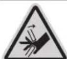
Keep hands away from the cutting area while the power tool is running. Contact with the saw blade can lead to injuries.
Wear a dust mask.
Wear safety goggles.

Wear hearing protection. Exposure to noise can cause hearing loss.
Danger area! Keep hands, fingers and arms away from this area.
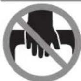
Keep your fingers away from the moving parts of the glide arm. There is a risk of fingers being crushed and severely injured.
3601M2704.
3601M27OL.
3601M2708.
3601M27OB.
3601M27OK.
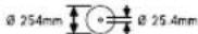
Take note of the dimensions of the saw blade. The hole diameter must fit the tool spindle without play. If it is necessary to use reducers, ensure that the dimensions of the reducer are suitable for the base blade thickness and the saw blade hole diameter, as well as the tool spindle diameter. Wherever possible, use the reducers provided with the saw blade.
3601M2700.
3601M2703.
3601M2706.
3601M2707.

The saw blade diameter must match the information specified on the symbol.
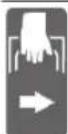
When transporting the power tool, hold it only at the locations (recessed handles) indicated.
Never carry the power tool using the handle of the glide arm.
Symbols and their meaning

For bevel angles, you need to adjust the left/right fence extension or completely remove it.

Clamping handle open: Bevel angles can be adjusted.
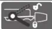
Clamping handle closed: The set bevel angle of the glide arm is locked.
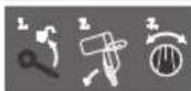
Indicates the individual steps for adjusting the bevel angle.
- Loosen the clamping handle
- Swivel the glide arm slightly to the left
- Set the required bevel angle range using the rotary knob
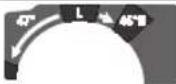
Setting the bevel angle ranges using the rotary knob:

Saw blade inclination to the left (45° to 0°)

Saw blade inclination to the right (0° to 45°)
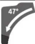
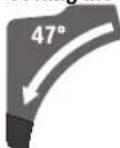
Entire swivel range of the glide arm (-47° to +47°)
To set a litre angle, the saw table must be able to move freely and the litre detent override must be blocked:

- Pull lever ① and at the same time push the litre detent override downward at the front ②.
Product Description and Specifications

Read all the safety and general instructions. Failure to observe the safety and general instructions may result in electric shock, fire and/or serious injury.
Please observe the illustrations at the beginning of this operating manual.
Intended Use
The power tool is intended as a stationary machine for making straight cuts in wood with and against the grain. It is possible to cut metre angles of -52^ to +60^ and bevel angles of 47^ (to the left) to 47^ (to the right).
The power tool is designed with sufficient capacity for sawing hardwood and softwood as well as chipboard and fibreboard.
When using appropriate saw blades, sawing aluminium profiles and plastic is also possible.
Product Features
The numbering of the product features refers to the diagram of the power tool on the graphics page.
(1) Dust bag
(2) Glide mechanism clamping lever
(3) Handle
(4) Lock-off function for on/off switch
(5) Protective guard
(6) Retracting blade guard
(7) Adjustable fence
(8) Fence
(9) Insert plate
(10) Mitredetent override
(11) Locking knob for all mitre angles
(12) Mitre pre-setting lever
(13) Clamping handle for all bevel angles
(14) Detents for standard metre angles
(15) Assembly holes
(16) Extension bar
(17) Recessed handles
(18) Extension bar clamping lever
(19) Screw clamp
(20) Guide roller
(21) Angle indicator for right-hand bevel angle range (0^ to 47^)
(22) Chip deflector
(23) Glide arm
(24) Depth stop adjusting screw
(25) Depth stop
(26) Transport safety lock
(27) Scale for bevel angles
(28) Angle indicator for left-hand bevel angle range (47^ to 0^)
(29) Adjustment knob for 22.5^ bevel angle
(30) Hex key (6 mm/4 mm)
(31) Scale for mitre angles
(32) Rotary knob for adjusting the bevel angle range
(33) Saw table
(34) Saw blade
(35) Dust extraction adapter
(36) Chip ejector
(37) Locking screw for the linkage of the retracting blade guard
(38) Linkage of the retracting blade guard
(39) Front fastening screw (cover plate/retracting blade guard)
(40) Rear fastening screw (cover plate/retracting blade guard)
(41) Cover plate
(42) Spindle lock
(43) Hex socket screw for mounting the saw blade
(44) Clamping flange
(45) Inner clamping flange
(46) Locking screw for the adjustable fence
(47) Damper
(48) Set screws for damping
(49) Holes for screw clamp
(50) Threaded rod
(51) Angle indicator for litre angles
(52) On/off switch
(53) Screws for insert plate
(54)/ Set screws for 0^ basic setting (bevel angle)
(55)/
(56)
(57) Set screw for 45^ basic setting (left-hand bevel angle)
(58) Set screw for 45^ basic setting (right-hand bevel angle)
(59) Set screws for litre angle scale
(60) Screw for mitre angle indicator
(61) Set screw for adjusting the clamping force of the clamping handle for any bevel angle
(62) Hook-and-loop strap
Technical Data
| Sliding metre saw GCM 10 GDJ GCM 10 GDJ | ||
| Article number | 3601 M27 04. | 3601 M27 00. |
| 3601 M27 0L. | 3601 M27 03. | |
| 3601 M27 08. | 3601 M27 06. | |
| 3601 M27 0B. | 3601 M27 07. | |
| 3601 M27 0K. | ||
| Rated power input W 2000 2000 | ||
36 | English
| Sliding metre saw GCM 10 GDJ GCM 10 GDJ | ||
| No-load speed min | -1 | 5000 5000 |
| Starting current limitation • | ||
| Weight according to EPTA-Procedure 01:2014 kg 31.6 31.6 | ||
| Protection class | ☐/II /II ☐ | |
| Dimensions of suitable saw blades | ||
| Saw blade diameter mm 254 254 | ||
| Base blade thickness mm 1.7-2.6 1.7-2.6 | ||
| Max. cutting width mm 3.2 3.2 | ||
| Hole diameter mm 25.4 | 30 | |
The specifications apply to a rated voltage [U] of 230 V. These specifications may vary at different voltages and in country-specific models.
Permitted workpiece dimensions (maximum/minimum): (see "Permissible workpiece dimensions", page 41)
Noise Information
Noise emission values determined according to EN 62841-3-9.
Typically, the A-weighted noise level of the power tool is: Sound pressure level 93 dB(A); sound power level 106 dB(A). Uncertainty K = 3 dB.
Wear hearing protection!
The noise emission value given in these instructions has been measured in accordance with a standardised measuring procedure and may be used to compare power tools. It may also be used for a preliminary estimation of noise emissions.
The noise emission value given represents the main applications of the power tool. However, if the power tool is used for other applications, with different application tools or is poorly maintained, the noise emission value may differ. This may significantly increase noise emissions over the total working period.
To estimate noise emissions accurately, the times when the tool is switched off, or when it is running but not actually being used, should also be taken into account. This may significantly reduce noise emissions over the total working period.
Assembly
- Avoid starting the power tool unintentionally. The mains plug must not be connected to the power supply during assembly or when carrying out any kind of work on the power tool.
Items Included
See the list of items included at the start of the operating manual.
Check to ensure that all the parts listed below have been supplied before using the power tool for the first time:
-
Sliding litre saw with mounted saw blade (34)
Locking knob (11) -
Clamping handle (13) with fastening set
Extension bar (16) and clamping lever (18) with fastening set
Dust bag (1) - Hex key (30)
Screw clamp (19)
Note: Check the power tool for possible damage.
Before continuing to use the power tool, carefully check that all protective devices or slightly damaged parts are working perfectly and according to specifications. Check that the moving parts are working perfectly and without jamming; check whether any parts are damaged. All parts must be fitted correctly and all the conditions necessary to ensure smooth operation must be met.
If the protective devices or any parts become damaged, you must have them properly repaired or replaced by an authorised service centre.
Extra tools required (not included in the delivery):
Cross-headed screwdriver
Ratchet spanner (size: 8 mm)
- Ring spanner, open-ended spanner or socket spanner (sizes: 10 mm and 17 mm)
Fitting individual components
- Carefully remove all parts included in the delivery from their packaging.
- Remove all packing material from the power tool and the accessories provided.
Fitting the locking knob (see figure a)
Screw the locking knob (11) into the corresponding hole above the lever (12).
Always tighten the locking knob (11) firmly before sawing. Otherwise the saw blade can become wedged in the workpiece.
Fitting the Clamping Handle for Various Bevel Angles (see figure a)
To fit the clamping handle (13), use the fastening set provided (socket spanner, nut, two washers).
- Place the individual components in the order shown (large washer, clamping handle, small washer, nut) onto the threaded bolts on the power tool.
- For better power transfer when tightening the nut, insert the hex key (30) provided through the holes on the socket spanner.
- Tighten the nut.
Fitting the Extension Bar (see figure b)
To fit the extension bar (16), use the fastening set provided (two clamping levers (18), two spring bolts, two knurled screws).
- Slide the extension bar (16) in as far as it will go into the corresponding holes in the saw table (33).
- Drive the knurled screws by hand into the corresponding holes.
- Place the clamping lever (18) on the head of the knurled screw.
Fix the clamping lever (18) in place using the spring bolt. - Increase the clamping force of the clamping lever (18) by tightening the spring bolts using the hex key (30) provided.
Stationary or flexible mounting
To ensure safe handling, the power tool must be mounted on a flat, stable work surface (e.g. work bench) before use.
Mounting on a work surface (see figure c1)
- Use suitable screw fasteners to secure the power tool to the work surface. The holes (15) are used for this purpose.
or
- Firmly clamp the base of the power tool to the work surface with commercially available screw clamps.
Mounting on a Bosch saw stand (see figure c2)
(GTA 2500 W, GTA 3700, GTA 3800)
With the height-adjustable legs, Bosch GTA saw stands provide firm support for the power tool on any surface. The workpiece supports of the saw stand are used for underlaying long workpieces.
Read all the warnings and instructions included with the saw stand. Failure to observe the warnings and follow instructions may result in electric shock, fire and/or serious injury.
- Assemble the saw stand properly before mounting the power tool. Correct assembly is important to prevent the risk of collapsing.
- Mount the power tool on the saw stand in the transport position.
Dust/Chip Extraction
The dust from materials such as lead paint, some types of wood, minerals and metal can be harmful to human health. Touching or breathing in this dust can trigger allergic reac
tions and/or cause respiratory illnesses in the user or in people in the near vicinity.
Certain dusts, such as oak or beech dust, are classified as carcinogenic, especially in conjunction with wood treatment additives (chromate, wood preservative). Materials containing asbestos may only be machined by specialists.
-
Use a dust extraction system that is suitable for the material wherever possible.
-
Provide good ventilation at the workplace.
- It is advisable to wear a P2 filter class breathing mask.
The regulations on the material being machined that apply in the country of use must be observed.
- Avoid dust accumulation at the workplace. Dust can easily ignite.
The dust/chip extraction system can be blocked by dust, chips or fragments of the workpiece. - Switch the power tool off and pull the mains plug out of the socket.
- Wait until the saw blade has come to a complete stop.
- Determine the cause of the blockage and eliminate it.
Self-generated dust extraction (see figure d)
For basic chip collection, use the dust bag (1) provided.
- Place the dust bag (1) onto the extraction adapter (35) and turn so that the pin of the extraction adapter locks in place in the recess of the dust bag.
During sawing, the dust bag must not come into contact with moving tool components.
Always empty the dust bag in good time.
Check and clean the dust bag each time after using.
When sawing aluminium, remove the dust bag to avoid the risk of fire.
External Dust Extraction
You can also attach a dust extraction hose (mm diameter) to the extraction adapter (35) for extraction.
- Connect the dust extraction hose to the extraction adapter (35).
The dust extractor must be suitable for the material being worked.
When extracting dry dust that is especially detrimental to health or carcinogenic, use a special dust extractor.
Cleaning the dust extraction adapter
To ensure optimum extraction, the dust extraction adapter (35) must be cleaned regularly.
- Pull the dust extraction adapter (35) off the chip ejector (36) with a twisting motion.
- Remove workpiece fragments and chippings.
- Reattach the dust extraction adapter to the chip ejector with a twisting motion until it engages above the chip ejector holding ring.
Changing the saw blade (see figures e1-e4)
Pull the plug out of the socket before carrying out any work on the power tool.
38 | English
Wear protective gloves when fitting the saw blade.
There is a risk of injury when touching the saw blade.
Only use saw blades that have a maximum permitted speed higher than the no-load speed of the power tool.
Only use saw blades that match the specifications given in this operating manual and that have been tested and marked in accordance with EN 847-1.
Only use saw blades that are recommended by the power tool manufacturer and are suitable for use on the material you want to saw. This will prevent the saw teeth overheating when sawing.
Removing the Saw Blade
- Bring the power tool into the work position.
- Loosen the locking screw (37) with the hex key (6 mm) (30) until the linkage (38) can hang freely.
- Loosen the fastening screw (39) (by approx. two turns) using the hex key (4 mm) (30). Do not unscrew the screw completely.
- Loosen the fastening screw (40) (by approx. six turns) using the hex key (4 mm) (30). Do not unscrew the screw completely.
- Pull the cover plate (41) forwards and downwards away from the fastening screw (40).
- Swivel the retracting blade guard (6) to the back and hold it in this position.
Hang the linkage (38) over the fastening screw (40) using a hole. This will hold the retracting blade guard open.
Turn the hex socket screw (43) with the hex key (6 mm) (30) and at the same time push the spindle lock (42) until it engages. - Keep holding the spindle lock (42) and loosen the hex socket screw (43) by turning it clockwise (left-hand thread).
- Remove the clamping flange (44).
- Remove the saw blade (34).
Fitting the saw blade
- When fitting the saw blade, make sure that the cutting direction of the teeth (arrow direction on the saw blade) matches the direction of the arrow on the protective guard.
If required, clean all the parts you want to fit before installing them.
- Place the new saw blade on the inner clamping flange (45).
- Fit the clamping flange (44) and the hex socket screw (43). Press the spindle lock (42) until it engages and tighten the hex socket screw by turning it anticlockwise.
- Release the linkage (38) from the fastening screw (40) and guide the retracting blade guard (6) back down.
- Slide the cover plate (41) back under the fastening screw (40).
-
Retighten the fastening screws (40) and (39).
-
Slide the linkage (38) into its original position and retighten the locking screw (37) using the hex key (6 mm) (30).
Operation
Pull the plug out of the socket before carrying out any work on the power tool.
Transport Safety Lock (see figure A)
The transport safety lock (26) makes it easier to handle the power tool when transporting it to various working locations.
Unlocking the Power Tool (Work Position)
- Press the glide arm (23) down slightly by the handle (3) to release the transport safety lock (26).
- Pull the transport safety lock (26) all the way out.
- Slowly guide the glide arm (23) upwards.
Locking the Power Tool (Transport Position)
- Slide the glide arm (23) all the way back and secure it in this position.
- Guide the glide arm downwards until you can press the transport safety lock (26) all the way in.
Further information: Transport
Locking the Glide Arm
The glide mechanism of the glide arm (23) can be locked with the clamping lever (2). The glide arm can be placed in two positions:
Glide arm pushed all the way back (for cross cuts)
- Glide arm pulled all the way forward (for a compact transport position)
Unlocking the Glide Arm (see figure B1)
After unlocking the glide arm (23), the whole gliding mechanism is ready for operation.
- Press the clamping lever (2) all the way down.
- The clamping wedge of the clamping lever releases the two articulated parts at the bottom of the glide arm.
Securing the Glide Arm (see figure B2)
Glide arm pushed all the way back:
- Push the glide arm (23) all the way back.
- The two articulated parts at the top of the glide arm are now upright and closed.
- Pull the clamping lever (2) upwards until the clamping wedge is positioned between the two articulated parts at the bottom of the glide arm.
- This locks the glide arm (23), which is pushed all the way back.
Glide arm pulled all the way forward:
- Pull the glide arm (23) all the way forward.
- The glide mechanism is now completely extended.
-
Pull the clamping lever (2) upwards until the clamping wedge is positioned between the two articulated parts at the bottom of the glide arm.
-
This locks the glide arm (23), which is pulled all the way forward.
Preparing for operation
Extending the Saw Table (see figure C)
The free end of long workpieces must have something placed underneath it or be supported.
The workpiece support on the saw table can be extended left and right using the extension bar (16).
- Push the clamping lever (18) inwards.
- Pull out the extension bar (16) to the required length (maximum 204 mm).
- To lock the extension bar in place, push the clamping lever (18) back out.
Moving the fence (see figures D-E)
When sawing mitre and/or bevel angles, you have to pull the left-hand or right-hand adjustable fence (7) outwards depending on the cutting direction, or remove it completely.
| 0°-47°(left) | ≤ 44°(right/left) | - Loosen the locking screw (46).- Pull the left-hand adjustable fence (7) all the way out. |
| 0°-47°(left) | ≥ 45°(right/left) | - Loosen the locking screw (46).- Pull the left-hand adjustable fence (7) all the way out.- Lift the adjustable fence upwards and out of the way.- Remove the locking screw (46). |
| 0°-47°(right) | ≤ 44°(right/left) | - Loosen the locking screw (46).- Pull the right-hand adjustable fence (7) all the way out. |
| 0°-47°(right) | ≥ 45°(right/left) | - Lift the adjustable fence upwards and out of the way. |
Adjusting the damping of the glide arm (see figure F)
The glide mechanism of the glide arm (23) is preset at the factory and is not damped when the power tool is delivered.
The damping of the glide mechanism can be adjusted using the damper (47):
Hard - for more controlled work movements;
Soft - for fast saw cuts.
- For softer damping, loosen the two set screws (48) using the hex key (4 mm) (30)
- or
- tighten the two set screws (48) for harder damping.
Clamping the Workpiece (see figure G)
To ensure maximum safety while working, the workpiece must always be firmly clamped.
Do not saw workpieces that are too small to clamp firmly.
- Press the workpiece firmly against the fence (8).
- Insert the supplied screw clamp (19) into one of the holes (49) intended for this purpose.
- Firmly clamp the workpiece by turning the threaded rod (50).
Setting metre and bevel angles
To ensure precise cuts, the basic settings of the power tool must be checked and adjusted as necessary after intensive use.
Experience and suitable special tools are required for this.
A Bosch after-sales service point will handle this work quickly and reliably.
Always tighten the locking knob (11) firmly before sawing. Otherwise the saw blade can become wedged in the workpiece.
Adjusting the horizontal litre angle
Setting Standard Mitre Angles (see figure H)
For quick and precise setting of commonly used mitre angles, detents (14) are provided on the saw table:
Leftward Rightward
0^
45°;31.6°;22.5°;15°15°;22.5°;31.6°;45°;60°
- Loosen the locking knob (11) if it is tightened.
- Pull the lever (12) and rotate the saw table (33) left or right to the required detent.
- Release the lever again. The lever must be felt to engage in the detent.
- Retighten the locking knob (11).
Setting any litre angle (see figure 1)
The mitre angle can be set between 52^ (left side) and 60^ (right side).
- Loosen the locking knob (11) if it is tightened.
Pull the lever (12) and at the same time push the mitre detent override (10) downward at the front. This locks the lever (12) and the saw table can move freely.
- Turn the saw table (33) left or right by the locking knob until the angle indicator (51) shows the required mitre angle.
- Retighten the locking knob (11).
- To loosen the lever (12) again (for setting standard mitre angles), pull the lever upwards.
40|English
The litre detent override (10) springs back into its original position and the lever (12) can click back into the detents (14).
Adjusting vertical metre angles
The bevel angle can be set between 47^ (left side) and 47^ (right side).
For quick and precise setting of frequently used bevel angles, stops have been provided for the angles 0^ , 22.5^ , 45^ and 47^ .
Setting the left-hand bevel angle range (45^ to 0^)

- Pull the left-hand adjustable fence (7) all the way out.
- Loosen the clamping handle (13).
- Use the handle (3) to swivel the glide arm (23) to the left until the angle indicator (28) shows the required bevel angle.
Hold the glide arm (23) in this position and retighten the clamping handle (13). The clamping force of the clamping handle must hold the glide arm securely in place at any bevel angle.
Setting the Right-hand Bevel Angle Range (0^ to 45^) (see figure J)

- Pull the right-hand adjustable fence (7) all the way out.
- Loosen the clamping handle (13).
- Use the handle (3) to tilt the glide arm (23) slightly to the left from the 0^ position and turn the rotary knob (32) until the required bevel angle range is shown.
- Use the handle (3) to swivel the glide arm (23) to the right until the angle indicator (21) shows the required bevel angle.
- Hold the glide arm (23) in this position and retighten the clamping handle (13). The clamping force of the clamping handle must hold the glide arm securely in place at any bevel angle.
Setting the Standard 0^ bevel angle
To enable the standard 0^ bevel angle to be reset easily, the rotary knob (32) engages in the left-hand bevel angle range.
- Swivel the glide arm (23) from the right to the 0^ position. Setting the entire bevel angle range (-47^ to +47^)
- Pull both adjustable fences (7) all the way out.
- Loosen the clamping handle (13).
-
Use the handle (3) to tilt the glide arm (23) slightly to the left from the 0^ position and turn the rotary knob (32) until the required bevel angle range is shown.
-
Use the handle (3) to swivel the glide arm (23) to the left or right until the angle indicator (28) or (21) shows the required bevel angle.
- Hold the glide arm (23) in this position and retighten the clamping handle (13). The clamping force of the clamping handle must hold the glide arm securely in place at any bevel angle.
Setting the Standard 22.5^ Bevel Angle (see figure K) Pull the adjustment knob (29) all the way out and turn it 90^ . Then use the handle (3) to swivel the glide arm (23) until you hear the glide arm engage.
Start-up
▶ Products that are only sold in AUS and NZ: Use a residual current device (RCD) with a nominal residual current of 30 mA or less.
Switching on (see figure L)
- To switch on the power tool, first slide the lock-off button (4) to the middle and then press and hold the on/off switch (52).
Note: For safety reasons, the on/off switch (52) cannot be locked; it must remain pressed during the entire operation.
Switching off
-To switch off, release the on/off switch (52).
Starting current limitation
The electronic starting current limitation feature restricts the power of the power tool when it is switched on and enables operation using a 16 A fuse.
Note: If the power tool runs at full speed immediately after being switched on, this means that the starting current limitation has failed. The power tool must be sent to the after-sales service without delay. For addresses, see: After-sales service and advice on using products.
Practical advice
General sawing instructions
Always tighten the locking knob (11) and the clamping handle (13) firmly before sawing. Otherwise the saw blade can become wedged in the workpiece.
Always tighten the locking knob (11) and the clamping lever firmly before sawing. Otherwise the saw blade can become wedged in the workpiece.
For all cuts, it must first be ensured that the saw blade at no time can come in contact with the fence, screw clamps or other machine parts. Remove any mounted auxiliary stops or adjust them accordingly.
Protect the saw blade against impact and shock. Do not subject the saw blade to lateral pressure.
Only saw materials which are permitted within the scope of the intended use.
Do not saw warped/bent workpieces. The workpiece must always have a straight edge to face against the fence.
The free end of long and heavy workpieces must have something placed underneath it or be supported.
Make sure that the retracting blade guard operates properly and that it can move freely. The retracting blade guard must open when the tool arm is guided downwards. When the tool arm is guided upwards, the retracting blade guard must close again over the saw blade and lock in the uppermost position of the tool arm.
Position of the operator (see figure M)
Do not stand in line with the saw blade in front of the power tool. Always stand to the side of the saw blade.
This protects your body against possible kickback.
- Keep hands, fingers and arms away from the rotating saw blade.
- Do not reach one hand across the other when in front of the tool arm.
Replacing the Insert Plates (see figure P)
The red insert plates (9) can become worn after prolonged use of the power tool.
Replace defective insert plates.
- Bring the power tool into the work position.
- Loosen the screws (53) using the hex key (4 mm) (30) and remove the old insert plates.
- Insert the new right-hand insert plate.
Screw the insert plate as far as possible to the right with the screws (53) so that the saw blade does not come into contact with the insert plate over the entire length of the possible slide motion. - Repeat the work steps in the same manner for the left-hand insert plate.
Permissible workpiece dimensions
Maximum workpiece dimensions:
| Mitre angle Bevel angle Height x width | |
| [mm] | |
| 0° 0° | 80 x 306 |
| 45° 0° | 80 x 216 |
| 0° 45° (left) | 54 x 296 |
| 0° 45° (right) | 30 x 296 |
| 45° 45° (left) | 54 x 208 |
| 45° 45° (right) | 30 x 208 |
Minimum workpiece dimensions (= all workpieces that can be secured left or right of the saw blade using the supplied screw clamps (19)): 145 x 306 mm (length x width)
Maximum cutting depth (0^ / 0^) .. 100mm
Sawing
Sawing without slide movement (cutting off) (see figure N)
- Slide the glide arm (23) all the way back and secure it in this position.
Make sure that the depth stop (25) is pressed all the way in and that the adjusting screw (24) fits through the recess without touching the depth stop when moving the glide arm.
- Firmly clamp the workpiece as appropriate for its dimensions.
- Set the required metre and/or bevel angle as necessary.
- Switch on the power tool.
- Slowly guide the glide arm (23) downwards using the handle (3).
- Saw through the workpiece applying uniform feed.
- Switch off the power tool and wait until the saw blade has come to a complete stop.
- Slowly guide the glide arm (23) upwards.
Sawing with Slide Movement (see figure 0)
- Maintain a firm grip on the handle before switching the power tool on and during the entire sawing process. Ensure that the movement of the glide arm is controlled during sawing. The glide arm is very easy to move and a moment of inattention could result in serious injury.
- Unlock the glide arm (23).
Check if the complete glide mechanism is operative by sliding the glide arm (23) back and forth.
- Firmly clamp the workpiece as appropriate for its dimensions.
- Set the required metre and/or bevel angle as necessary.
- Pull the glide arm (23) away from the fence (8) by the handle (3) until the saw blade is in front of the workpiece.
- Switch on the power tool.
- Slowly guide the glide arm (23) downwards using the handle (3).
- Now push the glide arm (23) towards the fence (8) and saw through the workpiece with uniform feed.
- Switch off the power tool and wait until the saw blade has come to a complete stop.
- Slowly guide the glide arm (23) upwards.
Adjusting the Depth Stop (Sawing the Groove) (see figure Q)
The depth stop needs to be adjusted if you wish to saw a groove or use a spacer.
- Swivel the depth stop (25) outwards.
- Use the handle (3) to swivel the glide arm (23) into the required position.
- Turn the adjusting screw (24) until the end of the screw touches the depth stop (25).
- Slowly guide the glide arm (23) upwards.
Special workpieces
When sawing curved or round workpieces, these must be especially secured against slipping. At the cutting line, there should be no gap between the workpiece, fence and saw table.
If necessary, you will need to manufacture special fixtures.
Working on mouldings
Mouldings can be sawn in two different ways:
42 | English
Positioning of Base moulding Crown moulding workpiece
- Placed against the fence

-Lying flat on the saw table
Furthermore, you can cut with or without the slide movement depending on the width of the moulding.
Always check the set litre and/or bevel angle first by making trial cuts in scrap wood.
Checking and Adjusting the Basic Settings
To ensure precise cuts, the basic settings of the power tool must be checked and adjusted as necessary after intensive use.
Experience and suitable special tools are required for this.
A Bosch after-sales service point will handle this work quickly and reliably.
Setting the Standard 0^ Bevel Angle
- Bring the power tool into the transport position.
Turn the saw table (33) to the 0^ detent (14). The lever (12) must be felt to engage in the detent.
Checking (see figure R1)
- Set an angle gauge to 90^ and place it on the saw table (33).
The leg of the angle gauge must be flush with the saw blade (34) along its entire length.
Setting (see figure R2)
- Loosen the clamping handle (13).
- Loosen the two set screws (54) (by at least one turn) using a socket spanner (10 mm).
- Loosen the set screw (56) (by approx. three turns) using the hex key (4 mm) (30).
- Tighten or loosen the set screw (55) using the hex key (4 mm) (30) until the leg of the angle gauge is flush with the saw blade along its entire length.
- Retighten the clamping handle (13). Then tighten the set screw (56) followed by the set screws (54).
If the angle indicators (28) and (21) are not in line with the 0^ marks on the scale (27) following adjustment, loosen the fastening screws on the angle indicators using a cross-headed screwdriver and align the angle indicators with the 0^ marks.
Setting the Standard 45^ Mitre Angle (left)
- Bring the power tool into the work position.
Turn the saw table (33) to the 0^ detent (14). The lever (12) must be felt to engage in the detent. - Pull the left-hand adjustable fence (7) all the way out.
- Loosen the clamping handle (13) and swivel the glide arm to the left stop (45^) by the handle (3).
Checking (see figure S1)
- Set an angle gauge to 45^ and place it on the saw table (33).
The leg of the angle gauge must be flush with the saw blade (34) along its entire length.
Setting (see figure S2)
- Tighten or loosen the set screw (57) using a ratchet spanner (8mm) until the leg of the angle gauge is flush with the saw blade along its entire length.
- Retighten the clamping handle (13).
If the angle indicators (28) and (21) are not in line with the 45^ marks on the scale (27) following adjustment, first
check the 0^ setting for the bevel angle and the angle indicators once more. Then repeat the adjustment of the 45^ bevel angle.
Setting the Standard 45^ Mitre Angle (right)
- Bring the power tool into the work position.
Turn the saw table (33) to the 0^ detent (14). The lever (12) must be felt to engage in the detent. - Pull the right-hand adjustable fence (7) all the way out.
-
Loosen the clamping handle (13).
-
Use the handle (3) to tilt the glide arm slightly to the left from the 0^ position and turn the rotary knob (32) until the right-hand bevel angle range is shown.
- Swivel the glide arm to the right stop (45^) by the handle (3).
Checking (see figure T1)
- Set an angle gauge to 135^ and place it on the saw table (33).
The leg of the angle gauge must be flush with the saw blade (34) along its entire length.
Setting (see figure T2)
- Tighten or loosen the set screw (58) using a ratchet spanner (8 mm) until the leg of the angle gauge is flush with the saw blade along its entire length.
- Retighten the clamping handle (13).
If the angle indicators (28) and (21) are not in line with the 45^ marks on the scale (27) following adjustment, first check the 0^ setting for the bevel angle and the angle indicators once more. Then repeat the adjustment of the 45^ bevel angle.
Aligning the scale for mitre angles
- Bring the power tool into the work position.
Turn the saw table (33) to the 0^ detent (14). The lever (12) must be felt to engage in the detent.
Checking (see figure U1)
- Set an angle gauge to 90^ and position it between the fence (8) and the saw blade (34) on the saw table (33).
The leg of the angle gauge must be flush with the saw blade (34) along its entire length.
Setting (see figure U2)
- Loosen all four set screws (59) using the hex key (4 mm) (30) and turn the saw table (33) together with the scale
(31) until the leg of the angle gauge is flush with the saw blade along its entire length.
- Re-tighten the screws again.
If the angle indicator (51) is not aligned with the 0^ mark on the scale (31) following adjustment, loosen the screw (60) using a cross-headed screwdriver and align the angle indicator along the 0^ mark.
Adjusting the Clamping Force of the Clamping Handle (13) (see figure V)
The clamping force of the clamping handle (13) can be adjusted.
Checking
- The clamping force of the clamping handle must hold the glide arm securely in place at any bevel angle.
Setting
- Loosen the clamping handle (13).
- Use a socket spanner (17 mm) to turn the set screw (61) anticlockwise to reduce the clamping force or clockwise to increase the clamping force.
- Set a bevel angle, retighten the clamping handle (13) and check whether the required clamping force has been reached.
Transport (see figure W)
Before transporting the power tool, the following steps must be carried out:
- Slide the glide arm (23) all the way back and secure it in this position (see "Securing the glide arm", page 23).
- Make sure that the depth stop (25) is pressed all the way in and that the adjusting screw (24) fits through the recess without touching the depth stop when moving the glide arm.
Guide the glide arm downwards until you can press the transport safety lock (26) all the way in - Push the extension bar (16) in fully.
- Set the bevel angle to 0^ and tighten the clamping handle (13).
Turn the saw table (33) as far as possible to the left and tighten the locking knob (11). - Wind up the mains cable and tie it together with the hook-and-loop strap (62).
- Remove all accessories that cannot be securely fitted to the power tool.
- If possible, transport unused saw blades in an enclosed container.
- Carry the power tool by holding it by the recessed handles (17) on the sides of the saw table.
Use only the transport fixtures to transport the power tool. Never carry the power tool by the protective devices, the glide arm (23) or the handle (3).
Maintenance and Service
Maintenance and Cleaning
Pull the plug out of the socket before carrying out any work on the power tool.
To ensure safe and efficient operation, always keep the power tool and the ventilation slots clean.
In order to avoid safety hazards, if the power supply cord needs to be replaced, this must be done by Bosch or by an after-sales service centre that is authorised to repair Bosch power tools.
The retracting blade guard must always be able to move freely and retract automatically. It is therefore important to keep the area around the retracting blade guard clean at all times.
Always remove dust and chips after working by blowing out with compressed air or using a brush.
Clean the guide roller (20) and the glide arm (23) regularly.
Accessories
| Article number |
| Screw clamp 1609 B06 203 |
| Insert plates 1609 B04 263 |
| 1609 B04 264 |
| Dust bag 1609 B02 595 |
| Dust extraction adapter 2 607 001 977 |
| Applies to the following models:3 601 M27 04. / ... 0L. / ... 08. / ... 0B. / ... 0K. |
| Saw blades for wood and fibreboard, panels and strips |
| 254 x 25.4 mm saw blade, 40 teeth 2 608 676 047 |
| Saw blades for hardwood, composites, plastic and non-ferrous metals |
| 254 x 25.4 mm saw blade, 40 teeth 2 608 640 969 |
| 254 x 25.4 mm saw blade, 40 teeth 2 608 640 970 |
| 254 x 25.4 mm saw blade, 40 teeth 2 608 640 971 |
| Applies to the following models:3 601 M27 00 / ... 03 / ... 07 / ... 06. |
| Saw blades for wood and fibreboard, panels and strips |
| 254 x 30 mm saw blade, 40 teeth 2 608 642 530 |
| Saw blades for hardwood, composites, plastic and non-ferrous metals |
| 254 x 30 mm saw blade, 80 teeth 2 608 642 528 |
After-Sales Service and Application Service
Our after-sales service responds to your questions concerning maintenance and repair of your product as well as spare parts. You can find explosion drawings and information on spare parts at: www.bosch-pt.com
The Bosch product use advice team will be happy to help you
44 | Français
with any questions about our products and their accessories.
In all correspondence and spare parts orders, please always include the 10-digit article number given on the nameplate of the product.
Great Britain
Robert Bosch Ltd. (B.S.C.)
P.O.Box 98
Broadwater Park
North Orbital Road
Denham Uxbridge
UB 95HJ
At www.bosch-pt.co.uk you can order spare parts or arrange the collection of a product in need of servicing or repair.
Tel. Service: (0344) 7360109
E-Mail: boschservicecentre@bosch.com
You can find further service addresses at:
www.bosch-pt.com/serviceaddresses
Disposal
The power tool, accessories and packaging should be recycled in an environmentally friendly manner.
Do not dispose of power tools along with household waste.
Only for EU countries:
According to the European Directive 2012/19/EU on Waste Electrical and Electronic Equipment and its implementation into national law, power tools that are no longer usable must be collected separately and disposed of in an environmentally friendly manner.
If disposed incorrectly, waste electrical and electronic equipment may have harmful effects on the environment and human health, due to the potential presence of hazardous substances.
Only for United Kingdom:
According to The Waste Electrical and Electronic Equipment Regulations 2013 (SI 2013/3113) (as amended), products that are no longer usable must be collected separately and disposed of in an environmentally friendly manner.
Français
Transport (voir figure W)
Robert Bosch (France) S.A.S.
www.bosch-pt.com/serviceaddresses
Outras indications: Transporte
www.bosch-pt.com/serviceaddresses
Eliminação
www.bosch-pt.com/serviceaddresses
Smaltimento
Stationaire of flexible montage
Afzuigadapter reinigen
www.bosch-pt.com/serviceaddresses
Afvalverwijdering
Taending (se billed L)
Bosch Service Center
Telegrafovj 3
2750 Ballerup
Pá www.bosch-pt.dk kan der online bestilles reservedele el-ler oprettes en reparations ordre.
TIf. Service Center: 44898855
Fax: 44898755
E-Mail: vaerktoej@dk.bosch.com
www.bosch-pt.com/serviceaddresses
Bortskaffelse
El-vaerktoj, tilbehor og emballage skal genbruges pa en miljovenlig maede.

Bosch Service Center
Telegrafvej 3
2750 Ballerup
Danmark
Tel.: (08) 7501820 (inom Sverige)
Fax: (011) 187691
Du hittar fler kontaktuppgifter till service har:
www.bosch-pt.com/serviceaddresses
Avfallshantering
Stille inn vertical standard gjaeringsvinkel 0^
Stille inn vertical standard gjaeringsvinkel 0^
- Sett elektroverktoyet i transportstilling.
Drei sagbordet (33) til hakket (14) for 0^ . Spaken (12) ma lases ordentlig i hakket.
Kontrollere (se bilde R1)
- Still en vinkelmaier pa 90^ og sett den pa sagbordet (33).
Armen pa vinkelmäleren ma flukte med sagbladet (34) over hele lengden.
Stilleinn(se bildeR2)
-Losne spennhandtaket (13).
-Losne de to stilleskruene (54) (minst 1 omdreining) med en pipenokkel (10 mm).
-Losne stilteskruen (56) (ca. 3 omdreiner) med unbrakonokkelen (4 mm) (30).
-Skru stilleskruen (55) inn erer ut med unbrakonokkelen (4mm) 30) til hele armen pa vinkelmaleren flukter med sagbladet.
- Stram spennhandtaket (13) igjen. Deretter strammer du forst stilleskruen (56) og deretter stilleskruene (54) igjen.
www.bosch-pt.com/serviceaddresses
Deponering
www.bosch-pt.com/serviceaddresses
Havitys
Tpoeiobonouoeic aopaleia yia paaltoonpiova
Ta paaltonpiova npoopicovra yia konj eluou n opei δov npoiovtw Eulou, 6ev mnpoe va xpnauonouv uε λeavtkoç biokouc konh γia kowjo otdpouxov ulikov, onocdkoi, pabdoi, kappiα, kλn. H λeavtkiŋ okov npokalei emlakot a kivoupeva epn, onwc o katw npoopuaKTnpac. O anivhepea no Tn λeavtkn konit qa kawourov kaTOW npoopuaKtnpa, to evthetayekontnc kai aa naatikaepn.
Xpoupoie Te apyktne, yia tvu unoopn Tou eneepyaocevou koupatou, onote elvau duvatov. Eav unootnpelte To eneepyaocveo kupat to xepi npeneva kpatate naVTOTxepaacto Alyotepo 100 mm ano kaee naeupa tou npiovodikou. Mn xpoupoite auto to npovla, ia va kowete kupatuaou eiva nolu mkpaa, yia vaoxtouve aopdaeaia va kpatnoouv te xepi. Eav to xepiaac elvai tonoetnevo nou Kovta oToV npovodisko, undpxeauenuevoc kivuvoc Tpaumatioou aoTnv enapj meTov npovodioko.
To eenepeyaojevo koumu tnpene va elvat akivnto kal oipuyevo na ouykpatei tnv w otov obnyo kal oto panel. Mn npoxvete to eenepyaoevo koumu t naww otov npiovodko h mnu kobetc (eaeepa) me onoiovdnote tpno. Ta avelekykta n kivouveva
eneEpyaOevaKouMaTa 0a unopouav va netaovupe uynanTayutnta, npokaWvta Tpaumaio.
ΣπρωΓE TO προvi ΜεσA ΘO ENEΕγραζΟν KOMμaTl. MγτραβηΓΕ ΘO Προvi ΜεσA ΘO ΘO ENEΕγραζΟν KOMμaTl. Γινα κανετε μΑ κοή, ΘΩΚωΤη ΘV Kεραλι TOUT Προνιου KAI ΠραβηΓΕ ΘV Eξω λανω ΘO ΘO ENEΕγλόμενο KOMμa TΘ Wφις KOM, Εεκινθετο TOUT KIVηΤηρα, Μεστε ΘV Kεραλι TOUT Προνιου KATW KAI ΠπρωΓΕ ΘO ΠεNEΕγραζΟν KOMμaTl. H KON ΘΩ διδρμη Ελεης εΙναι πθανόν VA ποραλεσι ΘV ἀνόθo TOUT προνδιακου ΘO ΘN ΘO ENEΕγραζΟν KOMμa TOUT KAI VΩIδει βίαia ΘO OUYKροτημΑ TOUT προνδιακου NAW ΘO Xeɪpιθη.
Iotepunv anawte To xepaacnavw ano Tny npoae nopeyn ypaum konc cire mnpoaraite niow ano tv npovobko. H unoanTou eenepeya0evou kouaTIOU OtaupwTa 6nA. KpatuvTac to eneepya0evo koumu ta ota deEia Tou piovobikou Me to apotepo aac xepi avtioptopa eivai nou enikivduvo.
Mny anawvet Ta xepia oac niow ano tov odnyo nio Kovra ano 100 mm ano kahe nau pao tpu npiovodikou, yva aapaepote Ta unolaemuata Euou nyia onoo-delta note AALOV Ayo, evo npiovodikoc nepiopepetai ypyopa. H anoataon Tou npyopa nepiotpepoevou npiovodikou ano to xepi oac mnpoei va my elva epaivnc kui npoei va tpaumatiote ooapap.
EeYTeTo eEepyaoevo kouaTnV nV kon. Eav To eEepyaOevo kouaiv KUPTwpeo h OteAawve, oipTe To Me TnV eWtepuKn KUPTwev n AuepaVa deixvei npoc Tov odnyo. Na Baeawveote naVtoe, otBev unapxe kevo metaTuou eEepyaZoeyou kouaTuou oyoukai Tou paneziou kat a Hkoc Tc ypaunnc Konnc. Ta Kupta nOtepaaewva eEepyaOeva kouaTia unpoi va nepiaTpaovuv v aetaTiotouv kai npoei va npokaleouv To aykwua Tou yopopa nepiaTpeoEvou npovobikoukai Tou tnv kon. Eev npenei va unapxoukappia nEeva avtkiepeva 0r eEepyaOevo kouaTl.
Mn xnpoonounoeTo nplovi pexvi ana oopakuv-0ouv ano to tpane2 ola ta epyaiaea, axpota Eua, K.AI., eKTOC ano To nEeepyaoevo koumu. Mkpa unoleimuata naLap a komuTia uou n aAvaTkeiueva, ta onoi epxovtaoe naof me Tov nepioteppevo npioVodioko mopei va nataoovuynanrTa.
KoBete tautoxpova mvo eva eneepyazopevo koumu. Ta oToiBayve naanla eenepeya0eva komuia dev mnpovvva aipxouv n va otnpixouv enapkwc kal npoei va maaykooov otov piovodiko n va metatomotov katn diapkeia tnckn.
Pivn xpon,betaawtheta,otto paaltonplovo elva stepewevo n tootheuve o e ma enine6n,otaepn emapaveia epyaaic. Mia enine6n kai otaepn enipaveia epyaia cmuwei tov kivduvo va kataotei to paaltonpiovo aotahec.
Piopypaariote nvyopaia oac. Kae popa nou aλaCETn puOuon TNC yoviac kaioc npaltooyviac, BepauwOeIre, otpuuizoevoc obnyoc elva puOu
ouoovoc ootia vtn unootnloen tou eneepya0evou kopauoi kai dev napeunodiei tv npiovobiko to ouostnua npooaioac. Xwpic va eveyonouoe to epyaleio (Eean 0rO ON) kai xwpic eneepyaoevo koupi OTO Tpanei, metakivote tv npovobioke o ma nipwc npoopoiwovn konm, ia va bebaowte, ot de Ta unapEe i paeumoidian kivuvoc konnc tou odnyou.
Aaheore enapkn unootnepi, onwc enektaoeic paneciou, kaaleta, kAn. yia eva eenepeya0evo koumuatou eiva nno nau t no paqu po aivai nio paia nio nana an to traned Tou qaltoonplovou npoei va avatpanov, av dev iival atnpyeva ae apaaea. Eav To koumevo koupatn to enepeya0evo koumat avatpanei, npoei va onkwoeTov katw npoopuktnpa na taXtei na wto npvopa nepipotepevo npiovdoiko.
Mn xonpoonoiie aAoo ato oocavtkaataaonmu c enktaon tpaneziou nwc npooctn unoortipn H aotaaocntpiien tou eepyafoevou koupatiou mnopei va npokaleoei tvv emakniou tou piovodikou htn metakiVon Tou eepyafoevou koupatiou katn diapkeia tnc Aetoupyiac ncc konic,tpaewrtac eoac kalto BOnO naov OTO ypnyopa nepiotpepoevo npiovodko.
To kouévo kouántδev npééva maaykθeɪ n va me-otei μe onoiobñntoe tpo naw otv yŋyopa nepoepóevnpovδiαko.Eav nepiopiεta,π.x xpnoi- monoiwtau avaotaleic mokouc,TO kouévo kouánti mopoel va opnywaet naov otv npovδiαko kalva tivaxteiμe δuvaun.
Xpmaonoei navto evav oipktnpa n eva npoap Tma, oxediaouevo yta n owtn unootnpien otpoyyu Lou uukou, onw paoboi n owlvcc. O pabdoivouv Tnv taon va kuioovuv wokovtai, e anotaleua npiovodioko cva mopei va apnacei kai va tpaBHei to eeneepyafoev komuat ni te xepaacnv npiovodioko.
AphoteTov npiovobioko va 0eotnv nAnp Tauxu TnTa npv Tny enaep m to eepyaoevo KmuAt. Auto ta peoetov kivduvo,va metaxte to eepyaooevo KmuAt.
Eav to eenepeyaojevo koupat no piovodokoc mlokaepi, anevepyonouote to paaltoopiovo. Tepeve ta otapatouov oaa ta kivoueva pepn kalp ahe To qic ao nTv npica tou pemuato cai apaipoeate Tny unatapia. Meta povviote va eueoepoae To mlokapoiye uuk. Eav ouvexoete To pioviqa me eva mlokapipevo eenepeyaoojevo koupati, mopei va npokwai anawlaia Tou eayou nqma oTo paaltoopiovo.
Metv oolokpan TNC konnc, apntote To biakomn eueoepo, kpatne Te Nkcpaah Tou npiovoukaw KI nepiEvete va atapatnoe O npovodiaoc, npotou aapaedeTo KoMuEvo KmuAt. Otav qdvete Me to xepoiac Kovta otov enipaauvoevo npovodioko elai emivduvo.
Kparate nλaβnσαθερa,otav kavete μa eλaunkomi n otav aφνεte eλeθερo tv διακοπη, npotou n κε-φaŋtou npoviou va βριακetal eντλωc σηv KATω
Oeog. H dpao n e0nnc tou npioiu o npoei va npokae i evaepviko tpaBnyu TNC kepAlnc Tou npioiu npoc ta kaT, me anotaleega kivduvo tpaumaiou.
Mny aphiote Tn xiepoalaen eaeuoeep, otav n npiovokepaan exeipaoaetnV kTu oeaon. Ondyeite Tnv npiovokepaan navtote me to xepi niaw otnv enawo ean. Otav n npiovokepaan kiveitauxupic eayxo, auto mopeia va onyneoi e kivduvo tpaumatou.
DiatnpieTe Tn 0ean epyaiaac aKaaOpH. Ta peiymuata uikov evai tiairepa emikivduva.Hokov n eapov pTaA npoei va avapvei n va ekpayei.
Mn xnpouoioieTe mKoPTEPOUC,payIOeouc/KAOTpeBawevoucpiovodikouc.MKnOPeoi npovdoikoi npovodiaokoi Me Aaooc kateuohvoeynobovwn auéavouv Tnv TpiβEgatiac Tnc NAOu oEvic oxmuic pioviaatoc,pokaaov Opivwau Tou piovodiaokou kalotaeta.
Mn xnpoioite npiovodikouc ano taxuaAubu npnhkpaatwoc (xalaHSS).Tetoi npovodokoi mopei va onaoov ekoia.
Xpnoiote navto npovobikouc e oawto meyehoc kai oxma (pojboe6c oe avti0en m To KukAiko) onovtou axova unofoxnic. O npovobikotou dev tiazouv mc ta uikac stepeownc tou npoviou 0a nepitopoeovtal ekcvtpa, npokawvta cTnv anwla Tou ecyxou.
Mny aapaieire note anokopata, anoBnTa Eluou n npoJoi anaTnv nepioxKoHc, otav tonkpiKO epyaieio biaketai oe ltoupyia. Osyeire npwraTov Bpaxiova Tou epaiaoi ont eoepuiac kai akaoaOwC anevpyonoe to naekptko epyaieio.
Mny niade teov npiovodioko meta nvyepyiaia, npo-touva kpuoei. Karatn diapkeia tnc epyaiaoc o npiovdoikoc zeaivetau uepBoiaka.
Σuβoλa
Ta ouβola nou akolouθouv mnoepi va exouv onuaia yia to xεipioo tou Μεκτριοu εpyαδiou oac.Πapakλομe anotu wtoσπνημoac ta ouβola kai tn onuaia touc. Hωσtn epunveia tow ouβδωv ouβαλe iσov kalutepo kai aφαλeotepo xεipioo tou Μεκτριοu oac εpyαδiou.
EeYxoc (BaeE cKovR1)
- Puoiote eva oipovwovio 90' kai the to nawo 0to tpane npiovicoatc (33).
To okeoc Tou oipoyovoviou npenei va eiva oe oO tou To mkoecuoypaumievoeTov npiovobio (34).
EAeyoc (BLeEeKoVa S1)
- Puoiote eva poipoywovio otic 45o kal oTe to nawo stpanei npiovioatoc (33).
To okeao Tou oipoyovoviou npenei va eivat oe oAo Tou To mkoecuoypaumievo Teovnpiovodioko (34).
Eeeyoc (Bene cikova U1)
- Puoiote eva oipoywovio 01c 90^ kai tonoetne to
muatau paayac odhyanoc (8) kai npiovodokou (34) enavw
oto tpaneipoviaqatoc (33).
To okeoTou moipoyuovoiou npenei va eivai oe oTO Tou To mkoEeuuypaumievo Tev npiovodioK (34).
www.bosch-pt.com/serviceaddresses
Anoupon
Ta nkeptika epyaia, ta eapntmuata kal ooukeuaite npenei va avakukawovtaipono pfuknpoc to nepiaaA lov.
Mny pixyve Ta nektpia epyaieia ota anopipmuata Tou anioouac!
Movi yia xwpec tnc EE:
www.bosch-pt.com/serviceaddresses
Tasfiye
Robert Bosch Sp. z o.o.
www.bosch-pt.com/serviceaddresses
Utylizacja odpadów
Bosch Service Center PT
K Vapence 1621/16
692 01 Mikulov
Na www.bosch-pt.cz si si muzete objednat opravu Vaseho stroje nebo nahradni dily online.
www.bosch-pt.com/serviceaddresses
Likvidace
www.bosch-pt.com/serviceaddresses
Likvidácia
www.bosch-pt.com/serviceaddresses
Eltavolitas
Kpntepnn npedeBbix coCToHHN
- nepetepnHnNoBpeKdEh 3neKTpuyeckn Kaebelb
- noBpeKdEn KOpNyc n3deInnA
TnHnepnoDnHocbTexHnueckoro 6cbnyxBaHHN
- PekomeHnyetcOuHCTnTb HHTpyMeHrOT nbINNocJe KaKDoTO NcNoJIb30BaHnR.
250|Pycckn
XpAHHeHne
- Heo6xOIMO xpaHnTB B cyXOM MeCTe
-Heo6xoJMO XpaHHT BdaIIN OT hCTOuHNKOB NOBblIeH HbIX TEMNEPAtp N BO3dEINCTBnCOnHeuHbIX Nyuei - npxpaHenn Heo6xOIMO H36eRaTb pe3KOro nepenada TemnepaTyp
-xpaenhe6e3ynaKOBnHeDonycKaetc - noDpoBHeItepeoBaHnK yCNoBnM XpaHeHnCMOTpHTe BFOCT 15150-69 (ycnoBne 1)
-XpaHbYyNAKOBKe ppeINpNRTn-H3rOToBHTeBACKnaDcKHX NOMEueHHX pN TEmpeAte OKpyKaIOueCpeblOT+5do +40^ .OTHOCTeBHAR BIAxHOCTb BO3dyHa He IOnKHn PpeBbIaTb 80%
TpaHcnpToPobKa
KaTeROpHueeCKn He DOnyckaetcnaDeHne HIOb6Be MExaHnueeCKHe BO3dEiCTBnHa yNaKOBky npH TpaHCnOpTHPOBKe
- npn pa3rpy3ke/norpy3ke He onyckaetc HcnoIb30BaHne IIO6oTo Bua TeXnKn, pa6oTaioe ne npHHunny 3aJkMa ynaKOBKn
- noDpO6HbIe Tpe6oBaHNK yCNOBnM TpaHCnOpTnpOBKn CMOTPHTE BTOCT 15150-69 (yCIOBne 5)
-TpaHcnopTnpoBaT npTeMnepaTypeOkpykaioe CpeBbO-50°Cdo+50°C.OTHOCHHTeBHaBnAxAHOCTbBO3Dyxa HeonKaHa npeBbIaTaB 100%.
Yka3aHnnoTexHnke6e3onacHOCTn
06uye yka3aHnno TExnke 6e3onachocTH nIa 3NeKtpoHHCTpyMeHTOB
NPEyPEXJEHNE
IpoountaTe Bce yka3aHn no TexHHKe 6e0naHocTH, HNCTpyKuHN, HNIOCTpaHcHcneuHcKaunH,
npeoctabneHbIe Bmectc HactOnuM 3NeKtpOnHCTpyMeHTOM. HecobnOeHne KaKHX-NH60 N3 YKa3aHHbIX HNKe HNCTpyKU MoKET cTb NpHuHOH NopApaKeHn 3NeKtpueCKHM TOKOM, NOXapa H/IN TRAKeJIbIX TpaBM.
CoxpaHnIe 3TH HnCTpyKuNN yKa3aHnN dnn 6yduoero nCNoB3OBAHnN.
IcnoIb3oBAHHoe B HAcTOruHx HNCTpyKunx H yKa3aHHx NOHTHE 3NEKTPOHnCTpyMENTPacPiocpTaHReTcHa3eKTPoHnCTpyMENTC nITAHmEOT cETn (C CTeBbIM shyPOM) HA aKKymIaTOPhBn 3NeKTPOHnCTpyMENT (6e3 cTeBoro shypa).
Be3onacnoctb pa6oery mecta
CoepKHe pa6ooye MeTo B uHcTote H xopoOo ocBeuHbIM. BeCnpaIOk HnH HeOCBeUeHHbIe yuaCTKn pa6ooyero MecTa MOrY npHBecTn K HeCuACTbIM CnyaAM.
He pa6oTaIe C 3neKtpOnHCTpyMeHTaMn BO B3pbIbO onaChOH aTMocpepe, HAnp., cOpEJauei rOpUne XHKOCTH, BOCPAmEHIOUncra Ra3bl NIN PbJb. 3NeKtpOnHCTpyMeHTb IckpT, YTO MOKeT pPiBecTH K BOCPAmEHHO IIIN INN napOB.
Bo Bpempa60bIc3neKtpOnHCTpyMeHTOM He DonycKaIte 6n3ko Baewemy pa6oemy Mecty Deten Hno
CTOPOHHHNII.OTBNEKUNCb,BblMOKeTe NOePbK KOHTPOJIb HAD 3NEKTPONHCTpyMENTOM.
O6OpyOBaHHe npEHa3HaueHO npa60bTB 6b10BbIX yCIOBHX, KOMMepuecknx 30Hax N O6IeCTBeHHbIX Me-CTax, pOn3BOJCTBEHHbIX 30Hax C MaIbIM 3JIeKTPoNtpe6JIeHnEM, 6e3 BO3dIeCTBnBn BpeHbIX nOAnChbIX npOn3BOJCTBEHHbIX paKTopOB. O6OpYOBaHHe npEHa3HaueHO n4KcIIpyatauHn 6e3 NoCToHHoro npCyTCTBnO 6cyyBaIOUero nepcoHana.
3NeKtpo6e3onacHocTb
WTeNCbHbBnK3NeKTPoHNcTpymeHTaONKHa noXoHbK WTeNCbHoP0eTke. Hn B KOem cny- yae He BHOCTe N3MeHeHHB WTeNCbHyO Bnky. He npMeHHte nepeXoHbIe WTeKebpI dN3NeK- TPOHNcTpymeHTOB C 3aunTHbIM 3a3EmneHHem. He3- MeHeHHbIe WTeNCbHbE BnKN I NOxODaJIne WTeNCbHbIe po3ETKn CHNXaOT pNCK nopaKeHHa 3NeK- TPOTOKOM.
PepoTbpaaTe TeneChbIK KOHTc 3a3emneHHblMNIOBepXHOCTAMN,KAKTO:CTpy6amH,3nEmeHTAMNOTIJIeHHKXYOHbIMNIIITAMHHXOIOHNbHKaMNIpn3a3emneHHBaWeroTena nobbiaaetc pck npapaeHHaJIeKTpOTOKOM.
3aunuatae 3neKtpOHnCTpyMeHOT OdoJN CbipoCTH.IPOHNKHOBEHHe BObl B3neKTPoHnCTpyMeHNT NOBbI-1WaeT PnCK NopaxKeHH 3neKTPoTOKOM.
He pa3peaetcHcnoB30BaTbUnhyp He no Ha3NaeHnIO.HNKoIa He HcNoNb3yIte Unyp dnn TpaHcnoptnPOBKn Hn NIOBeCKN 3NeKtpOHnCTpyMeNTA, Hn DnN H3BneEHn BnIKn H3 WTeNCenbHOJ po3ETKn.3aun-7aHTe Unyp OT BO3DeHCTBn BBICOKNX TempeaTp, Macna, OCPbIX KpOMOK Hn NIOBnKbIX qacte3NeKTPOHnCTpyMeNTA. NOBpeHHb nn CnyTaHHbUnhyp NOBbIwaet PNC NopaxEHHa 3NEKtPOTOKOM.
Pn pa6ote c3neKtpoHcTpyMeHTOM noOTkpblbIM He6om npmehnTe pnprohble n3TOrKa6eHNyDHHNTEN. PpmeHeHne npirodHor noPa6tbi noOTkpblm He6om Ka6eIyDHHNTEn CHNkaet PNCK nopaKeHH 3NEKTPoTOKOM.
EcnH HeBO3MOXHO N36ExKaTb npHMehHn 3NeKTPOHNCTpymeHTA B CbIPOm NOMEueHH, NOdKNIOaHTe 3NEKTPoHHCTpymeHT uepe3 yCTpoJIcTBO 3aUNTHORO OTKIOUeHH. PpIMHeHHe YCTpoIHCTBa 3aUNTHORO OTKIOUeHH CHINJAEt PICK 3NEKPTpuCeCKOro nopaKeHH.
Be3oNaChocThIIODei
BybTe BHNMaTeNbHbI, cneIte 3a TeM, yTo DeNaTe, H npOyMaHNo HaunHaTe pa60Ty C 3NeKtpOnHCTpyMeH TOM. He NnB3yIeTcB 3NeKtpOnHCTpyMeHToM B yCTaLOM COCToHHN Hn Nn NOB 03JeCTBHeM HApKOTkoB, anKOroJI Hn NEKapCTBeHHbIX CpeICTB. OINH MOMENT HeBHMaTeNbHocTH npi pa60Te C 3NeKtpOnHCTpyMeHToM MOKeT PnPBecTH K cepbe3HbIM TpaBMam.
PpHmEnHnTe CpeCTBa HnHBnDyAynBHO3aunTbI. Bcerda HocHe 3aunThbe OcKn.Hcnonb3oBAHne CpeCTB INnBnDyAynBHO3aunTbI,KaKTO:3aunTHOIMackN,06yBN Ha HeCKOnb3Jue NIOoWBe,3aunTHORO
JHMeMa HnCpeCTB 3aHtBOpraHOB CnyxA, B3aBNCMOCTN OT BnDa paBoTbC 3NeKTponHCTpyMeHTOM CHHXKaETPNCK NOnyuEHH TpaBM.
PpeoTbpaaHte HnpeDnHaMepeHnoe BKnOueHne 3NeKtpOHnCTpymEna. NpeTe KAK NOkIIOuHTb 3NeKtpOHnCTpymEnK Cetn H/nn K AkkyMnyTopy, PNOHtB HINNEPeHOCHT3NeKTPOnHCTpymEnY6eHNTecb, YTO OH BBkIOUeH. YepXaHHe NaIbca Ha BblKIOUaTeI pN TpaHCnOpTnPoBKe 3NeKtpOHnCTpymEnTa I NOkJIIOUeHHe K CETNITAHRA BKnIOUeHHO 3NeK- TPOHNCTpymEnTA YpeBaTO HeCuaCTHBIMn ClyuAAMN.
Y6npaTe yctahOBouhI HnCTpyMeH nIraeHbIe KIOUHO BKNIOueHHN3NEKTPoHNCTpyMeHa. NHTyMEHT NIN KIOU, HAXOJIAuNCB OBO BpaAIOUEcCACTN 3NEKTPoHNCTpyMeHa, MOKeT PnPBecTH K TpaBMam.
He npHmMaTe HeecctBeHHoe NOJoxeHne Kopnyca Tena.Bcerda 3aHmMaTe yctOuHBOe NOJoxeHne coxpaHnTe paBHOBeCne. BnaQdApA 3TOMy BbMoKTe LyUwE KOHTpOJIPOBaTb 3JeKTPoIHcTpymEHT B HeOXNDaHHbxCtTuacnX.
Hocnte noxoadyipoaboyo odexny.He hocnte 1npoky oedkny u kpaewn. Depknte BOncbI n OdeKdy Bdnn OT NOBnKnbIX Detanei. Wnpokar oede- kda, ykpaewn nn dinnHbte BOncbl Moryt 6bItb3aTHytbl Bpaauounmncra Yactrnn.
Pn HAnuHn BO3MOxHcT NcTaHOBKn NbIeOTCaBbBAOunN NbIeNC6OpHBx YcTPOcTB npOBepaTe NpncOeHNHeHne N npABINbHOe NCnONb3ObaHne. PnMeHeHne NblEOTcoca MoKET CHN3HTb OaCHOCTb, Co3daBaEMyIO PbIbIO.
XopoOee 3HaHHe 3NeKTPoHHCTPymeHOB, NOIyueHHO Bpe3yIbTaTe yAcTOrO Hx NcNOb3oBaHnH, He DOnJHo PnHBODHTb K CaMOyBepeHHocTH N rHOpHPOBaHNO TexHNK6e3oNaChOCTH ObaPeHnC 3NeKTPoHHCTpyMeHTAM. OdHO HeBpexKHe DeiCTBne 3a DoIIO cekyHdb MoKET pINBecTH K cepbe3HbIM TpaBMam.
BHIMAHHE!Bcnyae Bo3nHKnHOHeHn nepe6oBpa60Te 3NEKTPoHNCTPymeHTBaCNECTBnE NOHOrO HnN aCTHNOI pKePaueHHn3HePROChA6KeHHn HnN NOBpeXDeHHn CEHN ynpaBHeHHn 3HePROCHA6KeHHm YCTaHO BNTe BbIKNoUcATEb B NoIOKeHHne BbIKN. y6eINBUnCb, 4TO OH He 3abLOKpOBaH (npn erO hAnuHH).OTKIOUHTe CTeBYO BUNy OT PO3eTK NnN OTCoeHNHTe CBEMhBn AKKMyJrTOp. 3TNM PpeDToBpaAsTcR HeKOHTpONpyEmbl IOBtOpHbN 3anyck.
KbainuHpoBaHHbI NepcoHaB B COOTBeTCTBN C HAcToaUMpyKOBOCTBOMIOpa3yMeBaetNtU,KOTOpble 3HaKOMblcpeylnpOBKO,MOHTaXOM,BBOOM3KcNlYatauNo6cbNyKbAHnEM 3NeKTPOHNCTPymeTa.
Kpa6ote c3neKtpoHcTpyMeHTOM donyckaIOTc IHa He MOnOKe 18 net, H3yUHBnE TexHnueCkoe OINcaHne, HnCTpyKuIO NO 3KcnIyataunn INpabIna 6e3onacHOctn.
M3eHHe HnpEHa3HaueHO nINCnOJIb3OBaHHaNIIuAMn (BKNIOUAR DeTe) CNOHNKeHHbIMnΦH3NuCeCKHMn, UyBCTBeHHbIMn INIYMCTBeHHbIMn CnOCo6HoCTAmn INI INPOTCYTCTBMn y HNXKIN3HeHHORO ONbITaNIN 3HaHH, ECIN OHHe HAXODATC NOJ KOHTPOJEM INI He IpONHCTpyKTNU
poBaHbO6HCNoB3oBaHH3JeKTPoHHCTpyMeHTaIuOM,OTBETCBEHbIM 3a H6e3oNaCHOCTb.
PpHmHeHHe 3eKtpOnnHcTpymEnHa N o6paIeHne C HMM
He neperpykaite 3neKtpOHCTpymENT. McnoIb3yTe Dnpa6oTbcoOTBcTByUOuN CneuaHbHbI 3eK TPOHHCTpymENT.C NOxOJaUMM 3neKtpOHCTpymENTOM Bby pa6oTaete Nyuue HnadeXHoe B yka3aHOM dnaana30 He MoUHOCTn.
He pa6oTaIe C 3NeKtponHCTpyMeHTo m np Hnc- npaBHom BbIKIOATEne.3NeKtponHCTpyMeHT, KOTOpbl He noDaetc BkIOUeHIO IIN BbIKIOUeHIO, ONaCeH n DonKeH 6bITb OTpeMOHTPOBaH.
IpeepTeKakHactpaBt3eKtpOHCTpyMeHT,3a MeHbT pNHaDnEXHOCTH NnYbHpTa 3eKTPoHHCTpyMeHT Ha XpaHeHne,OTKnIOHTe UTeNCelbHyO BnIKy OT pO3ETKN CEtH N/NN BBiHbTe,ecn3TO BO3MOXHO,AKkMyJrTOP.3a Mepa npedocTopoxHOCTn PpEOTBpAaet HnpeDnHapeHHoe BKnIOueHne 3eKTPoHHCTpyMeHTa.
XpaHnTe 3NEKtpOHnCTpyMeHTb B HeNOctynHom dIeT MeTe. He pa3peWaTe NOb3OBaTbCa 3NEKTPOHnCTpyMeHTOM IuCaM, KOTOpBle HE 3HaKOMbl C HMM HnHe YHTaHn HAcToAUX HHCTpyKcN. 3NeKTPOHnCTpyMeHTb ONaChb B pyKaX HeONbITbIX NlU.
TuaTeNbHO yXaXnBaHte 3a 3neKtpOnHCTpyMeHToM npHaadNexKhoCTHM. IpOBepaIte 6e3ynpeHyo fYHKuHIO XoJ DBHXyUxxC4aCteE 3neKtpOnHCTpyMeHTA,OTcyTCTBHe NIOLOMK HNI NOBpeXdeHN,OTpHaTeNbHO BnHIOUxH Na FyHKuHIO 3neKtpOnHCTpyMeHTA. NOBpeXdeHHbIe Yactn DOJNXbIb 6bITb OTpeMOHTPOBAHbIO HCNOB30BAHH 3neKtpOnHCTpyMeHTA. IIOXoe O6cLyXnBaHne 3neKtpOnHCTpyMeHToB ABnAETc npHuHOr 6ObIwO YoCna HeCuaCTbIX CnyaEB.
DepxHTe peKyUHm HnCTpyMeHb 3aToeHHOM nHCTOM COCTOHHM. 3a6OTnBO yXoKeHHbIe peKyUHe INHCTpyMeHTb C OCTpbIMpeKyuHMn KpOMKaMn peKe 3a- KINHBaOTcH IN XnJIeYe BECTN.
PpMHMeHHe 3NEKTPOHNCTpyMeHT, pPHHaIeXHoCTH, pa6Oue HnCTpyMeHTbI H T. N. B COOTBeTcBHN C HAcTo- RmHnHCTpyKUmaHMy. YuHTbIbaTe npH 3Tom pa6OyHe yCNOBn H BblONHReMyo pa6Oy. IcNoJIb3ObaHne 3NEKTPOHNCTpyMeHTOB DnH enpeDyCMOTpeHHbIX pa60 MoKeT PpNBecTH K ONaChbIM CNTyaUHM.
DepxHte pyuKN H NOBepxHocTH 3aXbTa cyxHMn HcH CTbIMN, CNEHTE yTO6bHa HHN YTO6bHa HHN He 6blNO XIKKOHN KOCHCTEHNO CMA3KN. CKoIb3Kne pyuKN H NOBepxHocTH 3axbTa npenrTcByIOT 6e30nacHOMy ObaueHHIO C NHCPTpyMeHTOM H He daIOT HaedKHO KOHTPOINPOBaTb erO B HenpeBnDEHHbIX CNTyaunX.
CepBnC
Pemont 3neKtpOHCTpyMeHTa DOnJKe H BbINONHtBcT OTBKO KBaHNHnpuOBaHHbIM NepCOHaIOM TOnBJKO C npMHeHHeM opRnHaJIbHbIX 3aNaChbIX qacte.3TN M obecneuBaetc63oNacHOCT bNeKtpOHCTpyMeHTa.
Yka3aHnno TExnKe 6e3onachOCTn dnn ToQoBOuHO-yCope3OuyhIX nH
TopoBOOHO-yOpe3HbIe NnblpnpHa3NaueHbI npe3Kn DEpeBa HnoOp6hIX DepeBy MaTePhaIOB, 3anpeuaetcHX HCNoB3OBAHne C a6pa3HBbIMN OTpe3HbIMN DNCKAMH Dnpe3KN YepHbIX MetTALOB, HAnp.. npTyBeB, cTeXHei, uTTOB NT.D. PbIb ot IUnFOBAHIN BeDET K 3aeDaHIO DnKxUxxCraCTeH, HAnp., HnKHeRo 3aunTHOrO KOxyxA. NcPbI, o6pa3yUuHecr pN a6pa3NBHO pe3Ke, Mory npoxeYb HnKHN 3a- UHTbIKoKxyBCTABKY B npope3n dJIaNcKa n IpOuePiNACTIKOBIe qactH.
Bcerda, KOrda Bo3MoXHo, HcNoIb3yHte Ctpy6uHbI dIaФHKcaUH O6pa6aTbIAeMOJTeAIN. B cnyae npHepeKHNBaHnO 6pa6aTbIAeMOJTeAIN pyKo 683aTeJIbHO DePKeHTe pyKHa pacCToHH He MeHee 100 MM OT IIO60 N3 CTOpOH NInbHorO nCKa. He NC-ONb3yTE 3Ty NnHy dNp Pe3KN 3aTOrTOBOK, pa3Mep KO-TopbIX cNIuKOM MaI dNp HAdexKHO 3aKpENHn HnYdepKHNBaHnpyKoi. PnCNIuKOM 6NI3KOM paCINOJOxEHn pyKn OT INlbHoro DnCKA NOBbIaETcR pNCK TpaBMbl OT KOHTAKTc C INlbHbIM DNCKOM.
06pa6aTbIbAeMa3arotOBKa dONXHa 6bItb HenoDBHXHOH 3axaToH HnYdepKHBaTbC pyKo C onOpOIOHOBpeMeHNO Ha orpAXDeHne HnCAToH. HKOrJa He NOdaBaTe 6pa6aTbIBaEMyO 3arotOBKy NOHbHnDnck H He BbIOINHnTe pe3ky Ha Becy. He3aKaTbIE HnN DnBXKyUeNcE O6pa6aTbIBaEMbIe 3arotOBKnMOrTy 6bItb OTpoWeHbC 6OnbOu CKOpocTbU, YTO MoKET CTb PnPHHO TpABM.
PpotaKbAte NnBbHbIMcCK CKB03b 6pa6aTbIbAeMYO 3arOTOBky. He npotraHbAte NnBbHbIMcCKCKB03b 6pa6aTbIbAeMyIO 3arOTOBky Ha c6y. TTo6blcdeNaTpe3, NOHMITE rONOBKy Nnbln HnADBnBHe ee NoBepx 6pa6aTbIAeMoN 3arOTOBKn 6e3 pa3pe3AHN, 3anyCTNE DnHrataN, HnABNTe Ha rONOBKy NnblcCBEPX BHN3 INPOTONKHNTe NnblbIMnck CKB03b 6pa6aTbIbAeMyIO 3arOTOBky. Pe3aHne pIn DnBKeHHnHa ce6rCKopee BCero npBeTe K TOMY, yTO NnblbHmDnCK CAnET Ha 6pa6aTbIAeMyIO 3arOTOBky n 6yTe pe3KO BblpoWeh BCTOPOHy OnpaTopa.
Pyka HnKOrHa He DonxHa nepeceKaTh npednonarae MyIO NHHIO pe3a HN CnepeH, HN C3aH NnHbHorO nCk. PnpEpxHBaHHe 6pa6aTbBAeMoN 3arOTBKn nepeKepeeHNbIMn pyKaMn, T.e. yDepeXHBaHHe 6pa6aTbBaEMo 3arOTBKn cnpBa OT NnHbHO rCKa NeBOI pyKo nn HAObOpT, OueHb OnaCHO.
He npotraHbAte pyky 3a orpaXdHenne 6nHexe, cem Ha 100 MM ot IIO6o H3 CTOPOH NIIbHorO DNCKa, HN DnYydaIeHHaDpeBecHO CTpyKKn, HN DnYerO-N6o eue, ecHN Dnck eue Bpauaetc. BnH3ocTb Bpaauioe- roC8 PnIbHOrO DNCKa Kpyke MoKeT 6bItb HeNoOeHeHa, yTO MOKeT pINBECTN K TAKKeJIbIM TpaBMam.
OcmoTpTe 6pa6aTaBbAeMyo 3aROTOBky nepepe3aHnEM.Ecn 6pa6aTaBbAeMa 3aROTOBa HmEe T30rHyTuHn KpyuEnyOΦopMy,3aKpePnIte ee BHeHne NOBepxHOCTbIO HrN6a K orpaXdHnIO.Bcerda
CneHte 3a TEM, T06bI NO NHHN pa3pe3a OTCyTCTBOBAN 3a3Op MEXyO6pa6aTBaEMo3arOTOBKo, ORpaXDeHnEM H CTONOM. O6pa6aTBaEMble 3aTOBKN H3ORHYTo IIN KpyeHO FOPMbl MOYr peKepyTNTbcr IIN CDBHNyCBs, YTO MOxET PnIBeCTN K 3aeDaHIO Bpa- aHooeroc nHbHorO DNCKA BO Bpempe3Kn. B o6pa6aTBlaeMo3arOTOBKE He DoJnxHO 6bIt rBo3dE HIN HHOPoDnHexTl.
NcnoIb3yIte nHny tonbKO nocne toro, KaK cTOn 6yDen oUHHeOH BCEx HnCtpyMeHToB, O6pe3KOB DepeBa H T.D., 3a HCKIOUeHHem 6pa6aTBaEMO3arOTOBKn. MeKm MyCop mnn KycouKn DepeBa nn npOue npeMeT bI, BXoJ B KOHTaKT C BpaAHOUMCA NINbHbIM INCKOM, MOrTy 6bItb OTpoWHebl C 60JIbWo CKOpocTbIO.
Pexbte 0pb6aTbBAeMbte 3arotOBKn TOnbKo No OHn 3pa3.YIOKeHHBe CTONKO 0pb6aTbBAeMbte 3arotOBKn HEBO3MOXHO KaCneJeYET3aKaTb HIN CKePeNTb, NO3OMy OHN MOYr 3aKaTb NIIbHbI DnCK HIN CdBHyTB.CB BO BpeMpe3aHn.
IpeepncnojboaHem y6eHntecb TOM,TO TOPOBOHO-ycope3HAA HNA CMOHTnpoBaHa HN YCTAHOBHeHa POBHO, CTABNbHO paOoe NOBepxHocTH.POBHn H cTaNbHaa paOoay NOBepxHOCTb CHNkaetPnCK WataHn TOPoBOUHO-ycope3HO HNbl.
PnAnHpyTe cBOO pa60Ty. KaKdbI pa3 npn H3MeHeHH HAcTPOKNBepTKaNbHORo HnR TOpN3HTaNbHOrO yrna pacnna y6eHntecb B TOM, qTo perynpyEmoe orpaXdene nPaBnHbHO HAcTpoEHO nIy NOnDepKKn 6pbAsbTaBAeMOI 3arOTOBKn H He 6yDet MeMaTb nnhHomy DnCKy HnCtEme 3aunTbI. He BKIOUay 3NeKTponHCTpymEt B NOJoxKeHne n He NOMEua 6pbAsbTaBAeMyo 3arOTOBKy Ha CTOn, NOnHOCTbIO npOBe- dIte nnblbHdNCK NO BOo6paXaEMOMy pa3pe3y, YTO6bl y6eHNTcB OTCYCTBnN NOMex IIN OnaCHOCTn Nope3atb orpaXdene.
06ecneuBaTe aadeKbathyOnopy, Hanp., DononHnTebHbIe CToBb, Ko3bI N.T.D. nno6pa6aTbIBaEMo3aTOBKn, npBbIaOooep pa3mep cToNa no uHnpHe HIN DInHe. Ecnn 6pa6aTbIAEma3aROTBKa DnHHee HIN Wnpe CToTaTOPcOBOUHO-yCope3HO nnbl, To 6e3 COOTBETCTByIOSe ONOpbI OHa MoKet HAKPeHtCBc. Ecnn OTpe3aMaJ Yactb HIN 6pa6aTbIBaEMa3aROTBKa HaKpeHtC, OHa MoKet NODHTb HIXHN 3aUNTHbIK KOKyX HIN MOKET 6bITb OTbpOWeHa BpaAioUIMc NINbHBIM DnCKOM.
He hcnonb3yTe DpyrH NIOeB KaueCTBe IOnoHN HTe bHorO CTOna HnN NOpnpKn. HectabnbHaa ONopa 6pa6aTbBAeMoN 3arotOBKn MoKET pNBecTN K 3aXaTHIO NHBHO DNCKA HnN CDBRy Opa6aTaBbAeMoN 3aROTOKN BO Bpempe3aHHN, n3-3a Yero Bac N BaWero NOMUHNA KOKeT 3aTAYb NOD BpaauoONcra NlbHbI dNCK.
OpTe3aemar qactb He doJnxHa 6bItb 3aKaTa Hnn npHdABnHa Yem-ImHo K BpaauoUeMycnHbHomy DcKy.Pnp 3aKaTHN.T.e. pnp nCNoB3ObaHN ynap dYCTaHOBKn DInHbI,OTpe3aemar qactb MoKeT 3aKInHHTBCr NINbHbIM DNCKOM MOKet 6bItb pe3KO OTbPOWeHa.
Bcerda HcnoIb3yIte Ctpy6uHny Hn 3aXHMHOe yctpoIcBO, IpeHa3HaueHHe On HaedeKHO rKpenHn KpyIbIX MaTePhaNoB, HAp., CtePxHeHnn Tpy6. CtpxHH NcbHIO YKaTbIbAOTC Pn Ppe3Ke, H3-3a Yero NmblbHm DnCK MoXet "3akycblBaTb" n TnHyTb 0pa5abTaIbAemyo 3arotOBky BmecTe c pykO nOd nnblHbI dNCK.
Даite nHbHomy dNcKy pa3OrHaTbcrdo nonHoi cKOpoCTn nepeTeM, KaN pNkoCHyTbcr K 6pa6aTBiBaEMO3aROTOBKe.3To CHNkae TpCK OT6paCbIBaHHo 6pa6aTBiBaEMO3aROTOBKn.
Ecn06pa6aTbIBaemyIO 3aROTOBky HIN NINbHbI DnCK 3aeNO, BbIKIOUHTe TOPOBOUHO-yOpe3HyIO INny. IIOOXNITE, NOKA BCE DBrKxUneCe qactn He octahOBATCRA, H3BNEKHTe BUNKy I3 PO3ETKN CTe NHTAHNA/ INN H3BLeKHTe 6atapeo. 3aTe mOCBO6OHTe 3axaTbIMATEPnA.NcPiOnJXtB pe3At 3aeBwyo o6pa6aTbIBaemyIO 3aROTOBky, MOXHO yTPaNTb KOHTpONb HAD TOPOBOUHO-yOpe3HOINIOINIOINOBPeINb ee.
10 No 3aBepueHH pe3aHH, OTnycHTe BbIKIOuATenb, onyCTHe rONOBKY pINbI BHN3 N NOOxKNTe, NOKa PINbHbI dNcK He OCTaHOBTcN, NIMb 3aTeM y6paTte Ope3aHHU qactb. Pn6bnKaTb pyk K DnkyIeMycNo HnepuNN nINbHOMy DNCKy OnaCHO.
Kpenko depknte pyky, Bblonnna HenoNbI npope3 nnn OTnyckar BblKnOuateNb DO TORO, KAK TOnOBKa Nnbl NnHOCTbIO ONyCTNTcBHN3. Pnp TOpMOKeHHN nIbl TOnOBKy Nnbl MoKET BHe3aHNO NotAHyTb BHN3, YTO BeDeT K pNCKy NOnUyeHHa TpaBMbl.
He otnyckaite pykoRTky npn docthKeHHnnbHOnrOIOBkoIcAmoro HxKHeRo nOIOKeHH.Bcerda Bo3Bpaaate NnIbHyIO rONOBKY B cepXhee nOIOKeHHeBpyHyIO.BeckoHTpOJIbHOE DBHXKeHHe NIIbHOr rONOBKMOKET pINBeCTN K TpaBMam.
Codepkhtpepa0oee MeToB uHcTe. Cmecn MaTepnAnOBOCo6eHHOnaChb.IbIbJeKHXMeTaIIIOB MoKeT B03rOpTaBcHnnB3pblBaTbcra.
He npimehnre TynbIe, TpechyBnne, norHytbe HIN NOBpeKdEHHBe NInbHbe DnCKN. NInbHbe DNCKn C TybIMn HIN He npabHbHO pa3BeDeHHbIMN 3y6bHM BeyT B pe3yIbTaTe Oeyb y3Koro npOnnna K Nobbl WeHHOMy TpeHHIO, 3aKNHHBaHHIO nckKa N K o6paTHo My ydApY.
He npMehaTe nHbIe dNckn H3 bIcokOerHpoBaanHO 6bIcTpoepexyuee cTann (ctanb HSS). TaKe NCKMOrYTJeKo pa3NoMaTbcr.
Bcerda nCnoIb3yIte nnIbHbIe IncKn npaBnHoro pa3Mepa n c noXoJHm nocAoYhIM OTBepCTHe (HaNP.,pOM6OBuHoi HN KpyrNoi fOpMbI).IINbHBe INCKn, He COOTBETCTBYUOJIe KpeJeKhbIM qactrM IIbl, BpaauOTc a 6nHem N BeyT K Notepe KOHTpon HaH INCHTpymENTom.
HnKOrJa He ydaHnTe 06pe3Kn MaTePhana, cTpykky n T. n3 30hbl pe3aHH Bo BpMa pa6oTbI 3NeK- TPOHHCTpyMeHa. Bhaayane npBBeHnTe KpOHHTeH pa6oOero HHCTpyMeHa B COCTOHNHe NOKO H 3aTeM BBIKIO- qAHTe 3NEKTPOHHCTpyMeH.
He kacaTecb nHbHoro dNcKa noCne pa6oTbI, noka OH He octbIeT. Pn pa6ote nnbHbI dNcK cnBHO harpeBa-ETcR.
CNMBOJIbI
CneIyOuHne CHMBOIb MOYr HmTeB 3NaueHHe IIN HCIOB-3OBAHnBaWero 3NeKTPoHnCTpyMeHTa.3AnOMHnTE, noKaIyNCTa, 3TN CHMBOIb INx 3NaueHHe.IPaBnHoe ToIKOBaHnE CHMBOIb NOMoXeBamNyUWe HnHaedKHe pa6oTaTc 3TtM 3NeKTPoHnCTpyMeHTom.
CNMBONbl HNX3NaueHne
He noctabnIte pyKn B 30ny nneHnn npn pa6oTaouem 3NeKtponhctpymente. Pn KOHTaKe CnHbIM NICKOM Bo3HnKaet ONaCHOCTb TpaBMnpOBaHHa.
PpMHnHrTe npoTHBOBnBcBoeBopeCnnpaTOp.
HcnoIb3yIte 3aunTHbIe ouKn.

Hochte cpectBa 3aunTbOpraHOB cnya.BozdeIcTBne yMa moKeT npBecn K notepe cnya.
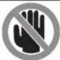
OnacnbI yuactOK! No Bo3MOxHocTHn depKHTe KNTn, naIbIu H pyKn noDaIbIwe OT 3TOrO yuaCTka.
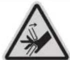
He BCTABNnTe nIbIb NODBHXHmOyT 6bITb3aKATbN3HaHTeBHtpaBMnPOBaHbl.
3601M2704.
3601M27OL.
3601M2708.
3601M27OB.
3601M27OK.
0254mm + 0254mm
3601M2700.
3601M2703.
3601M2706.
3601M2707.
0254mm 830mm
YuNbBaIe pa3MepbI NnHbHO DnKa. DnAmETp NOcAIOHOrO OTBepCTNa DOJKeH NOxOHTb K WnHdEnIO HNCTpyMeHTa 6e3 3a3Opa. PnH No6xoDnMOCTN IcNOB3OBaHHaNEpeXoHNKa CneITe 3a TEM, YTObIpa3Mepbl NEpEXoHNKa COOTBeTCTBOBaIIH TOnUHHe Tena DNCKa INaAMETpy NOCAIOHORO OTBepCTNa NnHbHO DnCKa,a TAKKe DnAmETpy NNHdEJIa HNCTpyMeHTa. PO B03MOXHOCTN IcNOB3yIte NEpEXoHNK, NOCTaBnREMbIE Bmecte C NnHbHbIM DnCKOM. DnAmETp NnHbHO DnCKa DOJKeH COOTBEcTBOBaTb DaHHbIM Ha CNMBONE.
CNMBONblnHX3HAueHHe
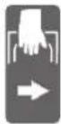
Ipn TpaHcnpTnpoBKe 3neK-TPoHHCTpyMeHTa DePKNTeCb ToNkO3a3THo603HaueHHbIe MeCTa (yrrny6nHnHnn 3axBaTa).
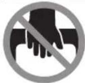
HnKOrda He nepeHocnte 3neKtpOnHCTpyMeHT 3a pyKoRTky Ha KpOHtTeHe.

PnBepTKaNbHbix yrnax pacnna neBbI nn npaBbI ydInHHTeNb ynpHOIIaHKn Heo6XoHMO npeDbuHyb IIIOBCEM CHrTb.

3aKHMHoi pblar OTnyueH: MOKHO HAcTpaNBAbBepTKKaIbHbIe yIbI paCnna.

3aKHMHpa pyka 3aKaTa: HAcTpoeHHoe Ha KPOHHTeHe 3HaueHne BepTKaJIbHO rYrna pacnna coXpaHReTcA.
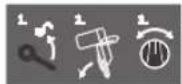
Ioka3bBaet nocneIOBATEbHOCTb
IeNCTBn npn hactpoKe BepTKaJIbHoro yra paCnna.
- OTnyCTHe 3aJxMHHyO pyKy
2.CnerKa HAKNoHTe KPOHHTeH BneBO
3.Повороною рукочустановerte Heo6xOIMMbIДиana3OH BepTHKaIbHbIXyIIOBpacnna
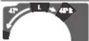
HacpoKa Dnana3oHOB BepTKaJIb HbIX yrIOB paCnna Ha nobopoTHOH pyKe:

HaKNOH HINbHOrO DnCKa BnEBO (45° ... 0°)

HaKIOH HINbHOrO DnCKa BnpaBO (0^ 45^)
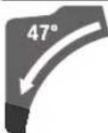
BecbHuaNaOHHaKIOHa KPOHHTeHa (-47^ +47^)
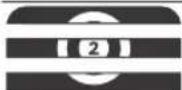
HnHaTPOKn npON3BOhBbIX rOpN- 3OHTaNbHbIX yrNOB paCnna CTOn nINbl DOnKeH CBO6oDHO nepemeuATbcn HnU yCTpOCTBO pa36nOKnpOBKn yrNa DOnXHo 6bIT 3a6nOKnpOBAHO:
-NotAHnTe pblur 1 N oDHOBpeMeH HOpKMMte yctpoCTBO pa36KnPOBKN yTna B nepeDneuactn BHn3.
Onncahne npoodykta n ycnyr

IpoHTHe Bce yka3aHn HnHCTpyKuHn To texHnke 6e3oNaChOcTH. HecobIoJeHneYk3aHn ITO TexHnke 6e3oNaChOcTH nHnCTpyKuMoKet PnBecTn K npaKeHIO3NeKtpnueckm TokOM, NoKApy N/nn TAgKeJIbIM TpaBMam.
IpoKanyhcta,co6JIIOJaIte HIIIOCTpaunB Hauane pykoBODCTBaNo 3KcNpyataun.
PpHMeHHeHnHa3HaueHHo
3JIeKpOHnHCTpymENT npedHa3HaueHdIcTaUHOAPHOI npMOnHHoH npOdoJbHOH nnonepuHou paCnIOBKn DpeBecNb.Bo3MOXHbI rOp30HTaJIbHbIe yrbl paCnna ot-52° 日 + 60^ n BepTnKaJIbHbIe yrbl paCnna ot 47^ (cneBa) do 47^ (cnpaBA).
MoJHocTb 3IeKTPoHNCTpyMeHTa paccuTaHa IJIЯ NIIeHnI TBePdOIN MRAKON DpeBecnHbI, a TaKKe CTpyKeHuBX IN DpeBECHOBOKNCHCTbIX NNIT.
PnHcN0b30BaHH COOTBETCTByUOxH NnHbIX INCKOB BO3MOXHO paCININBAHHe aIOMHNHeBix npOoHne I nIaCTMaCCbl.
H306paXeHHbIe COCTaBHeIy aactH
Hymepaun npedctabnHbIX KOMIOHETOB BbINONHeHa n0 3o6paKeHHo Ha cTpaHnue CnnIOCTpaIaMn.
(1)
(2) 3aJIMHONpUaMEXaHNMaCKoBKeHHN
(3) RykorTka
(4) BnokpaTOp BbKnIOuTeN
(5) 3aunTHbIKoKxH
(6) MaTHNKOBbI 3aUHTbI KoxyX
(7) Perynnyemay ynpnnaHa
(8) YnpnHa nHaHa
(9) Pnnta-BknaBbI
(10) YcTpoIcTBo pa36nOKnPbOKn yrna
(11) Φικυργύσηρ γυκα προύβόνος yrna pačnna (rρούθηταλόνο)
(12) Pbyar npedBapntelbHoh Hactpoyn yrna pacnna (ropn30HTaBHO)
(13) 3aKHMHa pyuKa dI npOn3BOJbHOrO yrna pacnna (BepTKaJIbHoro)
(14) HaceuHnIaHaH6oJeepacnpocTpahHeHHbIXyrgIOB (rOpi30HTaJIbHbIX)
(15) OTBepCTnIaI KpennenHn
(16) CkO6a-yDHHHnTeHb
(17) Yrny6neHnIgIaXbata
(18) 3axmmHOn pbuayr cko6bl-ynnnHnTeIa
(19) Ctpy6uHa
(20) PONIKCKOJIbXeHIN
(21) yka3aTeB yrrna paacnna npnHaKnOHe BnpaBO (0°-47°)(BepTKaJIbHoro)
Pycckn|255
(22) DeΦneKTOp cTpyKKn
(23) KpoHHTeHH
(24) HcnpoBOHyb BnHT OpaHnHTeYrIy6HB
(25) OrpaHnHTeNb Iy6HbI
(26) TpaHcnopTbI npedoxpahntenb
(27) kana yna pacnna (Bepnka horo)
(28) yka3aTeB yrna paacnna npn HakoNE BneBO (47^ - 0^) (BepTKaHbHO)
(29) TOnOBKaIINHACTPOIKN yrNa pacnna 22,5° (Bep
(30) KIIOU-WeCTINrpaHHNK (6MM/4MM)
(31) kana yna pacnna (ropn0htanbHoro)
(32) IobopoTHa pyka dna HactpoKN dHaNa3oHa yra pacnna (BepTKKaIbHorO)
(33) HnHbHbI CTON
(34) HnHbHbDnCK
(35) Aanter npbneydaenn
(36) NaTpy6okdNnBb6pocaOnnOK
(37) ΦHKCUPyUOuIN BnHT KOpMbICNa MaTHHKnOBOrO 3aUHTHOKoKyxa
(38) KopomboIcNo MaTTHKOBOrO 3aunTHOrO KOxyxa
(39) IpeepHn KpeeKhbBnHT (3aunTHa PnactHa/MaRTNkoBb 3auHTbKO- kxyx)
(40) 3aJHH KpeJeKbI BnHT (3aUHTHa INaCTHa/MaTHeKOBbI 3aUHTbIKo- kxyx)
(41) 3aunTHa nlaCTnHa
(42) Φικατορ χιπηνερη
(43) BnHT C BYTpEHHM WeCTHRpaHHKOM DnI KpenJIeHnI NIIbHOrO nUcKa
(44) PnHmHoiΦnaHeu
(45) BHyTpeneHn 3aXmHNO fnaHeu
(46) ΦHKCnpyuOuH BnHT peryI npyEmo ynpHOJ nHaHKN
(47) DEmnpep
(48) BnHtBnHaHcTpOKn DmNpHpoBaHH
(49) OTeBepTnIyIaCTpy6uH
(50) BHTCTpy6uHbI
(51) Yka3aTeB yrrna pacnna (rotnphtabHoro)
(52) BbIKIOuATeNb
(53) BnHTbI nIIITbI-BKnaDbIiA
(54)/ YCTAHOBOHTBIE BINTbI Dn6a30BOrO NNOXKeHHN
(55)/ 0^ (BepTnKaIbHbIy rOIn paCnnna)
(56)
(57) YctaHOBOUHbI BnHT dIg 6a3OBOro NIOJOxEHn4 45^ (neBbI BePTHKaJIbHbI yron paCnna)
(58) YctaHOBOUHbI BINT DnB 6a3OBOro NIOJOxEHn4 45^ (npabbI BeptHKalNbHbI yron paCNna)
(59) YctaHOBOUHbE BnHTbI WKaIbI yrna pacnna (ropn-3OHTaIbHoro)
(60) BnHT yka3aTeIy rna pacnHa (ropn3oHTaIbHoro)
(61) YCTaHOBOUHbI BNT HCT Cnbl 3aXIMa 3aXMHoN pyuK N Dn I pOHN3BOJbHOrO yTna pacnHa (BepTKKaIb-Horo)
(62) NHTa-nnyka
TexHHueckne daHbIe
MOnTaX Ha BepCTake npOn3BODCTBa Bosch (cm.phc.c2)
(GTA 2500 W, GTA 3700, GTA 3800)
Bepctakn GTA npon3BODCTBa Bosch oecneuBAoT yctO uBoe noloxhe He nktponHcTpymenta Ha IIO60 nobepx HocTH 5bIaropa perynpyembIM NO Bicote HOKKAM. Onop bI Bepctaka cnykat nnd noDpekk nnHHhix 3aRTOBOK.
Ipoptyte BCE npinnaeraembie Bepctaky npedynpeTeBbHbYe yka3aHHn HnHCTpyKuHN. HecobnoJeHne npedynpexKaJaoxN yka3aHn nHnCTpyKuM oKeT Bbl 3BaTb nopaxHeNe 3JIeKTPoTOKOM, noXap N/INn PnPBecTN K TReKeJIbIM TpaBMam.
PpabInbHO yctahOBHe BepCTaK nepeMDoHTaxOM 3NeKtpOnHcTpyMeHa. PpaBnBnaC6opKa cToNa BaX- HaI pPeOToBpaUeHn erO NOLOMKn.
-MoHTpyTe 3eNkTPOINHCTpyMeHT Ha Bepctake B IIOJKeHHKak dIra TpaHCnOPTnPOBKN.
ydaeneHne nbinn H ctpyKnn
Пьлн HeKOTOpbIX MATEpHnOB, KAK HAp.. KpacOK C COdePkaHnEM CBnHcA, HeKOTOpbIX COPTOB IpeBeCnHbI, MHepePANOB HMetaTIOB, MOKeT 6bITb BpeHOn DnIe 3DopOBbI. PnIKoCHOBeHne K bIyN IN NOJaHaHne PbIN BDbIXaTeNbHbIe NtIN MoKET Bb3BaTb anIeprInueckne peakun n/nn 3a6OneBaHnI dblXaTeNbHbIX nyTei OepaTopa Hn HaxOJaUeROCa B6nHn nepcoHana.
OnpeeneHHbI Bnbl nbHn, Hanp. ny6a n 6yka, cuntaotc KaHcepeoreHHbIM, Oco6eHHo COBmecTHO C npcaKamn dIn o6paobTKn DpebcHNbI (xPOMAT, cpeCTBO n3aunbl dpebecHNbl). MATEPHAN C codepkahem ac6ecta pa3pewaetc8 o6paabTBaTbToNko CneuaHnctAm.
-ПО BO3MOKHOCTH HcNoIb3yIe npHroIyIO IaMaTePnAHa CnCTemy NblNeYdaJIeHna.
-Xopoio npoBepnBaHte paOoe MeTo.
- PeKOMeHnyeTcN pONb3OBAbCpeCnnpaTopHOm MacKO c HnIbTpom KnaCa P2.
Co6nOdaTe DeIcTBYIOUne B Bauei cTpaHne npedncaHn. nIg o6pa6aTbIbAembIX MaTePnaIOB.
136eraTeCKoJIeHnIbINHa pa6OyemMeTe.1blbMOKETJERKOBOCIIaMeHrTbcR.
OTcOC nbHn/CTpyKKMOKet 6bITb HeBO3MOXeH3-3aNbHIN, CTpyKN, a TaKKe OTKOJOBWHxCfpaarmETOB 3aTOrTOBKN.
- BbIKIQUHTE 3JIeKTPoIHCTpyMeHT N BbITaUNTe WTeNCBn H3 pO3ETKn.
-ПОДОЖДNTe,пOKA ПИЛьhoe ПОЛТНО OCTaHOBITcI ПОЛHOCTbIO.
-HaHnte npnHHy 3aknnHbHaHn ycTpahnte ee.
Co6CTBeHHa ChTeMa bIneYdaneHn (cm.pnc.d)
Длпnpoctoro c6opacctpykkn npmehnTe noctabnembl nbIe6bOpHbMe0K(1).
BCTaBbTe HnakpyTHe nbIe6OpHbMeWOk(1)Ha aanTep nbIeYdaneHnra (35) TaKm O6pa3OM, YTO6bI WTEkep aanTepa nbIeYdaneHnRAoEN B 3auePHeHn B OTBepCTIN Ha nbIe6OpHOM MeWKe.
BoBpempa60tIbIeNc6OpHbI MeWOk HeDOnJKeH cOpnKacatbCnOdBKNHbIMN qACTMn HhCTpyMeHa.
CBoeBpeMeHHo onopoxHnTe nbIe6OpHbM MeoK.
PpOBepeHTe H ouHuaTe NbIeSc6OpHbM MeoK KaXDbH pa3 nocne HcNoB3oBaHH.
Bo n36exaHHe onaCHOCTn BO3rOpaHn CHMaTe IbI neBOH MeoK npH paCnne aIOMHHN.
Bheunnncntema nblneydanenHH
Дя удалени NBINK aanTepy nbIeOTbOda(35)MOxHO npCoeHNHTB BCaCbIBaIOUmNшnaH TbIeOCa(OMM).
-ПодcoeMHHTe Wnahr nbinecoca KaanTepy nbineoTbOda (35).
ПьilecocdoJXeH6bITb npHroJeHnIOBpa6aTbIbAemoromatepna.
PpimHeHrTe CneuaHbI NbIeCoc DnyyadeneoOc60BpeHbIX DnI 3DOpOBBy BNDOB NbIN BO36yDHTenepaKaHIN cyXOH nbII.
Ouictka aandaTepa nbIeyndaenHH
Дяобсесеня ONTNMAbHOrO nbIeYdaneHn Heo6xOnMo peryraHPO ouHsTa bAnTeP nbIeYdaneHn (35).
-CHMNTe aanTep nbIyDaeHnra (35), BbIKpyTNB erO c npatpy6ka nra BB6poca onnIOK (36).
- YdaJIHe 06bOMKn 3aROTOBKn H OINIKH.
-CHOBaHaJeHBe aanTep nbIeYdaJIeHnI, NOBOpaunBaeraero,Ha natpy6ok dIy Bb6pOca onIIOK,UTo6bl OH BoWeINB3aueIeHHe Hd 3axmHbIM KOnbOcm naTpy6ka dIy Bb6pOca onIIOK.
3aMeHa HnHbHorO ncka (cm.pnc.e1-e4)
PepedIIO6bIMMaHmnynraHmC3NeKtpOHCTpyMeHTOM BbITACKBaIte UTENCeIb H3 PO3ETKN.
Pn yctahOBKe NnIbHoro DnCKa HaeBaTe 3auHThBe nepyatKn. PnKoCHOBeHne K NnIbHOMy DnCKy MoXeT npHBecTN K TpaBMe.
PnIMeHReTe TOnbKO NnBbHe DnCKn C MaKcMaJIbHOI DoNYCTHMo CKOpocTbHO BbIe CKOpocTox Xonoctoro XoJa BaUero 3NeKTPOHnCTpyMeHTa.
258|Pycckn
PnIMHeHrTe TOnbKO NnBhBte DnCKn CnapaMeTpAMn, yka-3aHHbIMN B 3OM pyKOBODCTBE NO 3KCNpyatauIN, KOtOpbieNCbIHaBnIO EN 847-1 n HmEOT COOTBeTCTByOuOee o603Ha-ueHne.
NcnoB3yTeToIbKO NnHbHe DNCKN,peKOMeHNoBaHHbIe H3rOToBHTeMe 3NEKTPOHNCTpyMeHTa IN pnproHbIe Dn8 opaabaemoro MaepnaA.3To npedotBpaaet nepereB 3y6beB npn paCnniHaAHn.
DEmoHTaX NnHbHO DnCKa
-ПивдenteэнсгчмпВ pa6ooye noLoxhene.
-OTNCTHTeΦHKCHpyUHNI BHNT(37)C NOMOUBHO KHOaWIECTHRpaHHKa(6MM)(30),TObIKOPOMBICNO(38)CB6oDnHO CBNCano BH3.
-Ocna6bte KpeenexHbBnHT (39)(npHbI.Ha 2 06opota)c NOMOuBIO KIOUa-WeCTHRpaHHka (4MM) (30). He BbIKpyHBAIe BnHT NOHOCtBu.
-0cna6bte KpeenKhbBnHT (40)(npH6n.Ha 6 6obopoTOB) C NOMOUIIO KIIIOUa-IECTHpAHHHKa (4 MM) (30). He BbIKpyuBaIe BnHT NOHOCtBu.
OTTHHTe 3aunTHyIOIpaTHy (41)OTKpeNEXHO BnHTa (40)BnepeIN BnH3.
-OTKNOHHTeMaTHNIOBb3aUNTHbIKoKyX(6)Ha3aIN ydepKnBaIteeroB3TOM NONOKeHH.
-HaHeHbTe KOpMbICNo (38)OTBepCTHeM Ha KpeNekHbI BnHT (40).
BnaOapra 3TOMy MaTHNKOBbl 3aunTHbI KOxy ydepKNaBaETcB OTKpbITOM NIOJKeHH.
-ПОВОТAPИЗBAITe BINTC BHYTPEHHM
WECTHrpaHHKOM(43)C NOMOUsbKO KIOUa-
WECTHrpaHHKa(6MM)(30)NODHOBpeMeHHO HAXIMaIteHaФHKCaTOP UINHdJI(42),YTO6bl OH BOWeB 3aueHneHe.
-ДерхиTeФнCatopшINHdЯ(42)HAxKaTbIM NOHOBPeMeHHO BbIBePHNte BnHT C BHyTpEHNMWeCTIgpaHHKOM(43)No yacOBoCtpeKe(JIeBaJ pe3b6a!).
-CHMNTe3aXMHHOHΦaHeu(44).
-CHIMMTEINHbHbINDCK(34).
MOnTax nIbHorO dNcKa
CneDNTe 3aTeM, qTO6bI HAnpaBHeHne pe3aHHN 3y6beB (cTpeKHa HINbHOM NUCKe) COBnAdano C HApPaBHeHHem cTpeKN Ha MaTHNKOBOM 3aUNTHOM KOxyE!
Pn Heo6xOIMOCTH OUHCTNEpeM MOHTaXOM BCE MOHTpyeMbI yAcTb.
-HaHeHbTe HObBI NINbHbI DNCK HA BHyTpEHHN 3aXHM Hoi pHaheu (45).
-HaHeBte 3aJHMHOrΦJaHeU (44) IN BkpyTne BnHT C BHYTpEHHM WecTHpAHHKOM (43).PnKMTe PHKCaTOp WnIHdJIe (42),YTObI OH BOWeN B 3aCenNEHne,IN 3aTAHTE BnHT C BHYTpEHMM WecTHpAHHKOM NpOTNB YacBOBCTpeKN.
-CHMNTeKOPOMbICIO(38)CKPENEXKHOrO BNHTa(40)N CHOBA ONYCTNE MArTHNKOBbI 3aunTHbI KOxyX(6).
-Посунгье 3aunthyio nactHy (41) cHOBa noJ KpeNek-HbI BnHT (40).
-CHOBaTyro3aTAYHHeKpeNEXKbIeBnHTbI(40)H(39).
- YctaHOBITE KOPOMbICNO (38) BnCXoHoe NOIOKeHne HCHOBA 3aTAHHTe QHKCPyUOuN BnHT (37) KIIOYOMWeCTHrpaHHKOM (6 MM) (30).
Pa6ota c HhctpymehTom
Pepedn6bIMMaHHnynauHmC3neKtpOHNCTpyMeHTOM BBITACKBaIte UTenCeIb N3 p03eKN.
TpaHcnpOpThbI npedoxpAHntenb (cm.pnc.A)
TpaHcnpTHbI npedoxpahntelb (26) 6oNereta TpaHcnopTnpoBky 3neKTPoHHCTpyMeHTa K pa3nHbIM MecTa mpa60-Tbl.
ChrTne TpaHcnpTHoro npedoxpAHNTen (pa6ooye noJoxhen)
-ПрижмITE кронштейн (23) з рукову (3) сlerka BHH3,чобbl Chrtb Harpy3ky CtpaHcnpTHoro npedoxpaHHTeY (26).
-BbITAHHTe TpaHCnOpTHbI npedoxpAHNTenb (26) nonHOCTbIO HApKy.
-MedneHHo NOHMMTE KPOHHTEH (23) BBepx.
AkhBPOBaHne TpaHCnOpTHoro npedoxpAHNTen (TpaHCnOpTHoe nooXeHne)
-OTOBHbTe KPOHHTeH (23)do ynpa Ha3aH 3aФHKcIpyte ERO B 3OM NIOXKeHH.
-ПовернITE Кронштейн BнИЗ HabToIbKO,ЧTOБI TpaHc-NopTHBи npedoxpaHITeIb (26)MOxHO 6blIO NOnHOCbBOBdABNTb.
He 6pa6aTaBbAte 3arotOBKn, pa3mepbl KOTopbIX HeoctaTOHyI INx KpeHnEHH.
- Kpenko npnKMMTe 3arotOBky KynopHoi nHaHke (8).
BCTaBbTe npnnaIauyIOc cTpy6uHy (19) B Ondo n3 npedymcOTpeHHbIX dIg Hee OTBepcTHN (49).
-3akpenTe 3arotOBky BpaueHnEM BNHTa Ctpy6uHbI (50).
HactpoKa ropn3oHTaIbHorO n BepTnKaIbHorO yrna pacnna
IyoeceeneHToCHOrpaCnHaNoCnEHTHeCNBHO pa60tbHyKHO pOBepntb HCxOdHbe HAcTPOKn 3NeKTPoHNCTpyMeHTa NpH Heo6XoDMocTH NOINPaBHTb.
IyTOrO y BacdoJXeH 6bITb ONbI HcneHaJIbHbI INCTpyMEHT.
CepBnchna MaCTepckaa Bosch BbINOHReTakyio pa60Ty 6bICTPO HnHaJeKHO.
Dohayana nnneHHBcerda Kpenko 3aTnBaIte pyky fKncnpoBaHna (11).Haue nIbHbI dNCK MoKeT nepeKocITbcra B3aROtOBke.
Hactpoika rohp3oHTaIbHoro yrna pacnna
YctaHObKa cTaNdApTHOro rOpH3OHTaNbHorO yrna pacnna (cm.pnc.H)
IIN6bICTPOHTOUHOHACTPOHKnHaCTOHCNOB3yEmbx IROP30HTaJIbHbIX yrnoB paCnHa HINbHOM CTONE
npedycmOTpeHbHaCeueKn (14):
cneBa cnpaBA
0°
45°;31,6°;22,5°;15°;15°;22,5°;31,6°;45°;60°
-OTnyctnte pyky fHKcnpoBaHn (11),ecn OHa 3aTHyTa.
260|Pycckn
-OTTANTe pblar(12)HOBEPHTe NINbHbI CTON(33)DHyXHOH HaceKu BnEBO NIN BnpaBO.
-OTnyctte pbyar.PbayardoJKeH BoHTB 3aenneHHe Ha Haceye.
-3aTaNHe pyuKy qHKcnpoBaHH (11).
HacrpoKa npOn3BbHoro ropn30ntabHorO yra pacnna (cm.pnc.l)
TOpH3oHTaBbHbI yrO1 paCnHa moXHO perYnHPOBaTb B dnaana3oHe ot 52° (cneBa) do 60° (cnpaba).
-OTnycHTe pyky fHKCnpOBaHHa (11),ecn OH a 3aTAYTa.
-NotAHnTe pyuar(12)HOBPeMeHHO npKMMte yctpoCTBO pa36IOKNPOBkyra(10)BpeJeHueactn BHN3. 3TNM pKNCpyetc pyuar(12),N CTONIINbIMOXHO CBO6oHDnepeMeuaTb.
-Повернiteпиьсгл сгл (33)а руку Фнкрobанн
налево пин HanpaBOТak,чTOбы yka3aTeNBу rna pacnna
(51) yka3bIaN Tpe6yEmbI roPn3OHTaJIbHbI yron paCnna.
na.
-3aTaNHepepykyΦHKcHpoBaHHA11).
-4T06bI CHOBA Ocna6ntb pbuar (12)ДЯн HAcTpOKn CTaHJaAPThbIX rOpN3oHTaJIbHbIx yTNOB paCnHa),notAHnte pblayar BBepx.
UcTPOCTBO pa3bONKIOBKN yrna (10) BO3BpaauaetcB INCXOHOe NIOJOKeHHe, a pbyar (12) MOKET CHOBa BOITN B 3aueJIeHHe Ha HaceKax (14).
HactpoKa BepTKKaIbHorO yra pacnna
BepnkaIbHbI yron pacnnna MoKHO perynipoBaTb B dana3oHe ot 47° (cneBa) do 47° (cnpaBA).
ДябICTPOnITOHOnHACTPOKNaCTOHCIOJIb3yEmbIX BepTKaJIbHbX yRIOB paCnna npeYcMOTpeHbI yNOpblIg YrnoB 0^ 22,5°45"47
Hactpoika neBoro BepTKaIbHoro dHaana3oHa yra pacnna (45^ - 0^)

-BbBnHbTe neByo perynpyeMyo ynOpHyIO nHaKy (7) NOHOCTbO HApKy.
- Otnyctnte 3aJIMMHyIpyKy (13).
-ПовернITE Кронштейн (23)За руков (3)Влево дужно Верпкально угларпna Ha ykaataleугл (28).
- YdepKnBaIte KPOHHTeH (23) B 3TOM NIOXKeHHN CHOBA KpENKO 3aTRAHNTE 3aJHMHyO pyKy (13).
Cnna 3axHMa 3axHMHO pyuKINoJXHa 6bITb DocTaouHOH DnToro, UTo6bl KPOHHTeHN HaJeKHO DePKeANc B CBOEM NIOJoxEHNI pN JIOBOM BePTHKaJIbHOM yIne pacnna.
Hactpoika npaBoro BepTKKanbHoro dHaana3oHa yra pacnna (0^ - 45^) (cM. pnc.J)

- BbIbHbTe npaByIO perynpyemyIO ynOpHyIO nnaHKy (7) nonHOCTbIO HApJyK.
-OTnycHTe 3aKmMHyIpyKy (13).
—Cnerka HAKNOHTE KPOHHTeHH (23) 3a pyKoRTky (3) n3 NOXKeHH O° BNEBO H NOBOPaUNBaIte NOBOPOTHyIO pyKy (32) Do Tex nop, noka He 6yDen DocTHHyT Heo6xoDnMbI BePTNkAJIbHbI dHaIa3OH yrNoB paCnna.
-ПовернITE Кронштейн (23)а рукогу (3)Впраьду hyжноу угларacnnaHa ykaatae lyra (21).
- YdepnBaTe KPOHtEn (23) B 3OM IIOXeHHN N CHOBa KpeIKO 3aTnHTe 3aJHMHyO pyky (13).
Cnna 3axkma 3axmHNO pyuKN DoJNkHa 6bItb DocTaouHOH nToro, yTO6bl KPOHHTeIN HaedKHO depXanCBA CBOEM NIOJOKeHN pni IIO6OM BepTKKaIbHOM yrIpe pa-nna.
YcTaHOBka cTaNapTHOro BepTKKaIbHOrO yrna pacnHa 0°
Длгбнгчени NOBTOH NACTPOnK cTaNdaptHOrO yIa paCnIIa 0° nobOpOTHaR pyuKa (32)BXODHT B3aenneHHe Na dIana3OHe yIra pacnna.

3NeKTPOHHa CNTema ORpaHnueHnpyCKBOrTOkAOrpaHnHnBaetMOUHOCbPnBKKUOeHHN3NeKTPOHNCTpyMeHTa Ndaet BO3MOXHOCTpb60TbOTp03eTKHa16A.
Yka3aHHe: Ecnn 3neKtponHCTpymEn Cpa3y nocBkIoueH Hpa6oTaet C nonHbIM uCnOM o6OpOTOB, BbiWen N3 cTPOrOpaHnHTenb NyckOBOrTo KKa. 3neKtponHCTpymEn HyJHO HEmedHNOtnpaBnB B cepBnCHyO MaTePcKyO. Apeca: CepBnc H KOHCyNbTIpObaHHe NO BONpOCam PImMeHHeN.
Yka3aHnno npMmeHHnO
06une yka3aHnI nIeHHN
Dohayana nnneHnBcerda Kpenko 3aTnBaTe pyky fckncpoBaHH (11) n3axmhyo pyky (13).Ha-ue NIIbHbI dNCK MOKET nepeKOcHTcB B 3aTOrOBke.
Dohayana nnneHnBcerda Kpenko 3aTnBaIte pykyfHKcHPOBaHHA11 H3axHMHO pbuar. Hnaue NnblbHbIMNCKMOKe TpeKocNTCB B3aTOBOke.
He3aBnCHMo OT npOnHna, cHaana BbI DonKhbI NcKlHOHTb BO3MOXHOCTb pNkoCHOBEHH NIIbHOrO dNcKa K yOpHoi nAanKe, cTpy6uHAM Hn DpyHM qactHM HnctpyMeHa. Y6epNTe BO3MOxHbIE BCnOMoRatEnbHbIe yOpbl Hn COOTBeTcBEHHbIM 0pa3OM NOrOHHe HX.
3aunuane nnbHbe noToHa ot yapob H tonKOB. He HaKmMaTe c6Oky Ha nnbHbI dNCK.
PacnHnBaIe ToIbKO MaTePnAbI, DonyueHhBc B COOTBeCTBn C H3aHaueHEm HHTpyMeHTA.
He 6pbabtbaIte nokopobneHbIe 3arotOBKn. 3arotOBKa dONKHa BcERda NMeTb npMyK KpOMKy IJI pNknaDbBaHHa K ynpHOH PnAHe.
HINHHbIe I TAKKeIbe 3aTOrTOBKn HxKHO NOIpePeTb HIN NOIOXKNtB YTO-HN6yNb NOI HNX.
Oecnebte hncpabHyko fyHKuIO MaTHNKOBOro 3aunTHoRto Koxyxa n er0 Cbo6oHnoe DBHXeHne. PnOnyckAHN KPOHHTeHa BnH3 MaTHNKOBbl 3aunTHbI KOKyX DOJKeH OTKpbIBaTcB. Pn NODHATNI KPOHHTeHa BBepx MaTHNKOBbl 3aunTHbI KOKyX DOJKeH ONrTb 3aKpbITcR HaINlbHIM DnCKOM IN BOITN B 3auePHeHne B CaMOM BepxHem NOLOKeHH N KPOHHTeHa.
TonoxeHne onepatopa (cm.pnc.M)
He cToIe nepe3 3neKtpOHcTpyMeHtOM B Ody HnHIO C NnHbHIM DNCKOM, CToRb HxKHO BcERda C6Oky B CmEueHHOM NO OTHoWEHN K NnHbHOMy DnCKy NOnoXeHN. TaKm o6pa3OM Bbl MoXeTe 3aunITb ce6r OT BO3MOXHOrO pIKoWeta.
-He noctabnaIte pykn n naIbcuI noB bpaauounncn HnhHhN DNC.
- He ckpeuBawte pykn neped kpoHtEHom.
CmeHa nHT-BKnaDbIwei (cm.pnc.P)
Pocne npoJOnKHTeBHO npmHeHn3NeKtpOHnCTpyMeHTa BO3MOKeH H3HOC KpaChbIX nIIT-BkJaDbIWe (9).
3aMeHnIte HeNCpABHbIe nnITb-BKlaDbIiN.
-ПиВeДпЕЗЛЕКТРОИСТРУМЕТВ pa6Oуee noLOJOKeHne.
-BbIKpyTNE BnHTbl (53) C NOMOuBIO KINOua-WeCTNpAHHnKa(4MM)(30) INCHMITE CTAPBIE PNTbl-BKNaDbIiN.
-BIIOXInTe HOBbIe IcnpaBbIe IINITbI-BKNaIbIbIu.
-ПиВHTIe ПИTY-BKlAdbIbW BHTaMn (53) KaK MoXHo DaIbIe CnpBaTaK, YTO6bI NO BCEH O3MOxHO TAROBOrO DBHXeHn HCKIIuOaIOcB CoPnKOCHOBeHne PINbHOrO DnCKaC NITOnB-KklaDbIeM.
-AHANOHTNO NOBTOPNE 3TN paBOOne ONEPAUN DnHO BOI NEBOI NITbI-BKNaDbIbIa.
Donyctmble pa3mepb3arotobkn
MaKcHMaJIbHbIe 3aTOrTOBKn:
OrpaHnHTeB rny6nHb Heo6xOIMO nepeCTaBtB,ecnBam HyXHO BblnHb Na3 HcNoIb3OBaTb DnCTaHIOHHyNpOp.
-Повернiteоrgаанчтendeуби(25)наруж.
- YCTAHOBNTe KPOHHTeHH (23) C NOMOuBHO pyKoRTKN (3) B HYXHoe NOLOXKeHne.
- Otperynpyte KcHPOBOUHb BnHT (24) TaK, YTObI eO KOHeC Kacanca ORpaHHuTEna Iy6HbI (25).
-MeDneHNOIOHNMITEKPOHHTeIH(23)BBePx.
CneunbHbIe 3aROBKn
IINI O6pa6OKN H30rHbIX HIN KpyrNbIX 3aRTOBOK Bbl DOnKHBi 3aΦNKcHPOBaTb Hx C cenbIO ppeDtBpaueHnckOJIeHHHa IINHH pe3a He donyckaetc BO3HNKHOBeHHe 3aOpa MEXyD 3aRTOBKO, yNOPHO PeKo H CTONOM.
PnHHeo6xOaHMoCTn CneJyET H3rTOBHTb CneuaNbHbI KpeNek.
06pa6oTka npoΦnIbHbIX peek
PpOHHbHbIe peKn BblMOXeTe 6paTaBtBaTb DByMa pa3- HNHyBIMCnOcO6aMn.
HacpoiKa Cnbl3aXHMa 3aXHMHOpyK (13) (cm. pnc.V)
Cnny 3aJIMMa 3aJIMHOI pyuK (13) MoKHO peYIpOBA Tb. KoHTpOJIb
-Cnla3aKIMa 3aKIMHOpyKNdoJNkHA6bITbDOCTaTOU-HOHINrTO,YTObIKPOHHTeHNHaJeKHOepKaIcB CBOEMNOLOXKeHHPiNIObOMBepTKaJIbHOMytne pa- nHa.
Hacroka
-OTnyCTHe 3aJHHMHyOp pyKy (13).
-NoBepHHTe yCTaHOBOUHbE BnHTbI (61) C NOMOuBTOTOP OBOrO raeHOrO KIOHa (17 MM) IPOTNB YacOBo CTpeKN, YTObI yMeHbWHTb CNy 3axKMa, INN NO YACOBo CTpeNKe, YTObI yBeHNUTb CNy 3axKMa.
-HactpoTeBepKanbHbYrOaPacnna,CHoBa3aTAHte 3aXmHyOpyky(13)InpOBepbTe,6bIaNIOCTHRhyTa Heo6xOIMMaCnla3axnma.
TpaHcnpOpTHpOBKa (cm.pnc.W)
Ipeep TpaHcnpTnpoBkO 3neKtpoHCTpyMeHTa BbINOHNHe cnedyuuee:
- OToBnHbTe KpOHHTeH (23) Do ynpa Haazn 3aФHKcpyte ero B3OM IIOJXeHH (CM. «ФнкcaIGN KpOHHTeHa», CTp. 23).
-86eHITecbBTOM,TOO rpanuHTenbIy6nHbI (25)NON HOCTbIO pNkAT BOBHTpb,aIOCTnPOBOOHbIN BNT (24) npn nepemeueHHKPOHHTHa npoxoHTpe3OTBeP CTHe, He 3aEBA OraPauHHTenbIy6nHbI.
-Повернг Кронштейн BнИЗ HabToIbKO,ЧTOБI TpaHc-NopTHBипpeOxpaHnTeIb (26)MOXHO 6blIO NOnHOCbBOBdABNTb.
-CDBnHbTe yDHHHTeIbHbIe cKo6bl (16)do ynpaB HappaBHeHn ceHtpa CToJa. - YctaHOBnTe BeptnKaJIbHbI yron cKocA B O" n 3aTnHTe 3aTJHKHyO pyKy (13).
-ПовернITE столпь (33)do ynpa BneBOи 3atЯнite pykyфксюван (11).
264|Pycckn
-CB8KHTe ceTeBOI Ka6JIb c NOMOUIIO HeHTbl-JINnyuKN (62).
-CHMMNTe c3neKTPoHHCTpyMeHTa Bce npHaJnEkhOcTH, KOtOpbIe He 3aKpENJIOTc npOuHO Ha MaUNHe.
- IpehenochtnHbHbIe NcKn, KOTOpBIMN BbI He nOJb3yeTeCb, NO BO3MOXHOCTN B3aKpbTbIX EMKOCtA.
-Переньостеэнкгюнсчрмента рукдлпегонockn(17),pacnoLOXeHHbIeNo6OKamnnHbHorOcTona.
ДлгТранспорТровьн ЗЕКТРОНСТРМЕТА HСПONь 3уITE TOnbko TpAHCNOPTPhOBOчьиpe npCnOC6BENH NHH B Koem Cnyuae He HcNoIb3yIte ДЯ 3TOrO 3aUHTHbIe npCnOC6BENH, KPOHHTEH (23) nHpyKoRTKY (3).
TexobcnyxHBaHne n cepBnC
Texo6cnyxHBaHne n ouNCTka
PepedIIO6bIMMaHHyNAUHmC3NeKTPoHNCTpyMeHTOM BbITACKBaHTe WtENCeNB H3 p03ETKN.
Длгобсесуенкаусьтбунибezогнpa60-TbI coDEpKHTe 3NEKTPoHnHCTpymEn H BeHTNlaHNoH-HbI epope3H B uHcTOTE.
Ecni Tpe6yETc NOMEHATb WHyp, BO n36eKaHHe ONaCHOTN oBaPaaIteCb Ha aHpy Bocsh uB aBtOpn3oBaHHyO cepBnCHyIO MaTepckcyIO IIN 3NeKtpOnHCTpyMeHTOB Bosch.
MaTHKOBbH 3aHTbHKOxy DoJKeH BcERda CBO6OHO DBHaTbCn H CaMCToTeIbHO 3aKpbBaTbCn. NoTOMy BcERda DEpXNTe B uCTOTE yAcTOK BOKpyr MaTHKOB0 3aUHTHO KOxyxa.
Iocne kao do pa6oey onepaun ydaanre nbIn n ctpyK Ky cTpye Cxatoro Bo3dyxa nn KCTOOK.
-Perynlpno Ouyuatape pONKCKOJIbXeHHN (20) IN KPOH-1THe (23).
Peann3aunno npoykunn pa3peeaetc npo3bo0ntb B mara3nnax, otdenax (cekunx), naBnbohax nKnockax, o6ecneYBaIOUnx COXPAHHOCb npOyKUnn, NCKIOUHOUX nonaDaHHe Ha He aTMocfepHBIX OCAkOB IN BO3deIeCTBHe ITOHKNOB NOBbIeHNbIX TEMpeApTy (pe3KOrO nepenada TempeAtp), BTOM YNCNE cONHeuHbIX Nyey.
IpoaBeu (H3rOToBnTeIb) 6o3aH npedocabTb NOKynte IHOe0xOIMyIO IOCTOBepHyIO HΦopMaunio O npOdyKcN, 06ecneuBaOuyIO B03MOXHOCTb ee npaBNbHO Bb6opa. IHΦopMaunio O npOdyKcN B 6o3aTeNbHom nopAKe DOnkHa coepKaTa CBedeHn, nepeueh KOTopbix yCTaHOBHe 3aKOHoDaTeBCTBOM Poccncko Fepaoun.
Ecnn npno6peMaHa nOte6nTeH mpoDyKuHa 6bIna B yNtpe6nHm HnB HeYcTpaHnC HEDocTaOK (HeoctAtKn), nOte6nteIIO DoJXHa 6bItb PpeoCTaBHeHa HfOpMa- qna 06 3Tom.
B npouecce peann3aun npodyukun doJnxhbl BbInnoHrbcn CneyuOuune Tpe6oBaHH 6e3onacHOCTN:
- PpOaBeu O63an DOBecn IIO CBeEHHN NOKyNaTeHn HmEHHOHaMHeOBAHHe CBOeOpraHn3aUN, MeTo eHaxOxJDeHHA (aDpc) npeKIM ePabToI;
-06pa3bI npOdyKuINB TOpROBbIX NOMEueHnX DonxNbI 0ececneuBaTb BO3MOxHcOCTb O3HaKOMJeHnNPOkyntaTeIa
CHaIINHcAMn HA H3dEINHX NCKIOUaTb IIO6bIe CaMOCTO TReBHeIe DeNCTBnI NOKyNaTeNe C H3dEINMn, PnBO DaIue K 3aNycky H3dEIN, KpOME BN3yAaNbHOr OCMOTpa;
-ⅡpOaBeueo83anDObcTnDO CBeHnN POKyNaTeHnHΦopMaunIO NOITBepXJdEHn COOTBetCTBn 3TNx H3deHnn yctahOBHeHHbIM Tpe6oBaHnM, OHaJIuHn ceptnHkKatOB Hn DeKnapauN O COOTBetCTBnH;
-3anpeaaetcpeaH3aun npOdykun npn OTCYCTBn (ytpate) eHDeHTNΦKAUHOHBx PnH3aKOB, C HCTekuHM cPOKOM rOHOCTn, CNEAMN NOpH IN63 HCHTpKuNN (pyKOBOCTBA) NO EKnnyataun, 0b3aTeNbHoro cePTnΦkata COOTBETCTBna IIN60 3HaKa COOTBETCTBn.
PpnaHuaJIeXHoCTN
| Артыкуньний Нмер | |
| Сtrубцина 1609 B06 203 | |
| Плты-Вкладыши 1609 B04 263 | 1609 B04 264 |
| Плтыев мених 1609 B02 595 | |
| Даалтетпьдуаленя 2607 001 977 | |
| Демстентельно дд се dedуошх тноб:3601 M27 04./_0L./_08./_0B./_0K. | |
| Плтыные диски дд.depeBa n scintobix MaTePhaNoB,паелей и peek | |
| Плтынд диски 254 x 25,4 MM, 40 3y-6beB | 2608 676 047 |
| Плтыные диски дд.Tberdoй дpeBeCnHbI, KOMpo3nO-HNbIX MaTePhaNoB, ПlaCTMaCCbI u CBeTHbIX MeTAllOB | |
| Плтынд диски 254 x 25,4 MM, 40 3y-6beB | 2608 640 969 |
| Плтынд диски 254 x 25,4 MM, 40 3y-6beB | 2608 640 970 |
| Плтынд диски 254 x 25,4 MM, 40 3y-6beB | 2608 640 971 |
| Демстventaльно дд се dedуошх тноб:3601 M27 00./_03./_07./_06. | |
| Плтыные диски дд.depeBa n scintobix MaTePhaNoB,паелей и peek | |
| Плтынд диски 254 x 30 MM, 40 3y-6beB | 2608 642 530 |
| Плтыные диски дд.Tberdoй дpeBeCnHbI, KOMpo3nO-HNbIX MaTePhaNoB, ПlaCTMaCCbI u CBeTHbIX MeTAllOB | |
| Плтынд диски 254 x 30 MM, 80 3y-6beB | 2608 642 528 |
CepBn KOncynbTHpObaHne NO BOpocam npmeHeHH
CepBnchbI OTeI OTBeHT Ha BCE BaHn BOpocbl no peMoHTy I o6cnyHbAHIO BaWero npOdykta, a TaKke No 3aNactrM. N3o6paKeHHc nPoCTpaHCTBeHHbIM pa3deneHHem DeNaTe HnHfOpMauNo 3aNactm MoXHO NOCMTpeTb TaKke no aDpecy:
www.bosch-pt.com
KoNneKTHB COTpydHnKOB Bosch, npedocTbnaIounn KOHCyNbTaun Ha npedMeT NcNoJIb3OBAHn IPOdyKUn, C yDobOBtBmE OTBeNT Ha BCE BaUN BONpOcBi OTHOCTeNB HOrO HaWe npOdyKUn N ee npHaNDexKHOCTe.
Ioxanynta,BO Bcex 3anpocax n 3akazax 3anacteyn 6n3aTeNbHO yka3bBaate 10-3naHbTobapHbH HOpE no 3aBODCKO Ta6nue H3denn.
Длретона: Pocсь, Бенихтан, Укpanha
FapaHTnHoe 06cnyKbAHne n peMOHT 3NEKTponHCTpyMeHa, c 0cbIOHeHem Tpe6oBaHN HOpM 3rTOBtEnI npOu3BOATCA HA TeppNTopMN BCex CTpaH TObKO B @npMeHHbIXnn ABTOpN3oBaHHbIX cepBNCbIX ueHTpax «Po6epT BoU”.PPEyIPeXKeHNE! McNoJIb3oBaHN KOHTpaKaTHOH npOdyKun OnaCHO B 3KcNlyatauIN, MoKet pPiBeCTN K yuepe6yJnBaWero 3dOpOBBy. N3rTOBNeHne n pacnpoCTpaHeHne KOHTpaKaTHOH npOdyKun IpcecJeYETCn NO 3aKohy B aMHHnCTpaTHBOM n YrOToBHM NOPaKe.
Pocchra
YnonHomOueHHaHn3rTOBHTeMeOpraHHaZaH:
000 «PobepT Boiu» BaulytnHcKoe Wocce, Bl. 24
141400,r.XmKn,MockOBckar 06J.
Ten.: +78001008007
E-Mail: info.powertools@ru.bosch.com
www.bosch-pt.ru
IOnonHntBbIe apeca cepBnchbIX ueHTpoB Bbl NaJeTe no CcbInke:
www.bosch-pt.com/serviceaddresses
Bcnyae bixoDa 3eKtpOnHCTpymEnTa n3 cTPOB TceHeHepaHTnHO rpoKa 3KcNpyatauNN NO BnHE N3ROTOBHTen, BnaIeneU HMeET npABo HA6ecnAATbHr rapaHTnHb peMoHT, npCobIOdEHn CneDyUOx YcNOBn:
OTCYTCTBMEMexaHueCKNX NOBpeXdEHN;
OTcyTCTBnEPn3HaKOB HApyuWeHHa Tpe6oBaHn pyko-BOCTBA NO 3KcIpyatau
- Haniue B pykoBODCTBE NO 3KcNpyaTaun OTMeTKn IpODaBuO npoDaeKe NpOINCH NOKynteIra;
COOTBETCTBNE cepHHO HOMepa 3NEKTPONHCTpyMeHTa INCEPHHOMY HOMepy B rapaHTN Hom TaIOHe;
OTCYCTBNE CNeIOB HEKBAHnΦuNPOBaHHO peMOHTa.
TapaTnH he paacnpoctpaHReTcHa:
JIIO6bIe IONOMKn, CBA3aHHbIE CΦOpC-MaXOpHbIMN 06CTO- RTeINbCTBaMn;
-HOpMaIbHbI H3HOC: 3JIeKTPoIHcTpymEHTa, TaK JKe, KaK IN BCE 3JIeKTPnueckne.
IapaHTneHneNOKpbBaetcpeMOHT,NOTpe6HOCTbKOTOPOMBO3HnKaETBCNECTBHeHOpMaNbHOrO H3HOCA,COKpa-zaIOJeroCpOK Cnyk6bl TaKHXaCTeINHCtpyMeHa, KaIPncoEOHNHTenBHe KOHTaBtI, NPOBOa, IETKN.
-ecTeCTBeHHbI IN3Hoc (NONHaBbIpa6OtKa pecypca);
-06opyoBaanHe n erO qacn, BbIXoI n3 cTpoKOTopbix CTa CNEcTBnEM HnPaBnBHOY cTaHOBKN, HecaHKUHOHnPoBaHHo MOHnΦKaun, HnPaBnBHOrO pInmHeHnA, HapuWeHne npaBnO bCnyXBaHHn XpaHHeH;
-HeNCpAIBHOCTH,BO3HNKUHNE BpeyIbTaTe neperpy3KN 3NeKTPoHHCTpyMeHTa.(K6e3ycNoBHBm npn3HaKaMa nepe
rpy3kn HnctpyMeHTa OTHocTc: NOBHeHne CBeTa No6eKanocTN, DeOpMaun nn ONnabNeHne DetaneN y3NoB 3NEKTPoHnCTpyMeHTa, NOTemHeHne nn ObyIINBaHne I3OJIuNN PPOBOOB 3NEKtpoDBnraTeNn PoD JeCTBnEM BbICOKo TEMnepaTybl.)
Yttnn3aun
OTcnyKBWNE CBOI cPOK 3neKTPoHNCTpyMeHTbI, npHnAd- neXHOCTN ynaKOBky cNeDyET cDaBaTb Ha 3KOJOnHueCKn H- CTyo peKyepauuO OTxOIOB.
YTNIN3NpyTe 3NeKtpOnHCTpymeHT OTdIbHOOT 6bIbTOBO Mycopa!
TobkoДЯнСТРан-ЧЕнов EC:
B cootbetcbn cEBponecko dHpeKTHBOI 2012/19/EU 06 OTPa6oTahbIX 3NEKTPnuECKHX HNEKTPoHHbIX np6opax N ee npeo6pa3oBAHNEM B hauNoHaJIbHOe 3aKHOJaTeJIbCTBO HerOJHbIe 3NEKTPoPnH6Opby HxHIO Co6HpTa bOTJeJIbHO n CdaBaTb Ha 3KOJIoRHeCKn UCHTyO peKyNepaHIO.
PnHnPaBnBHoYttnn3aunOpTa6oTahHbE 3neKtpueckne H3neKtpoHHbIe Pn6opbl Morytok3aTb BpeDHOB3deNCTBHe Ha OKpykaioyUcpeyN3doOpBoe YenOBeka n3-3aBO3MOXHOIPOncyTCTBnB HnXOnacbIXBeIeCTB.
yKpaIHcbka
Bka3iBkn 3Texhikn 6e3nekn
3araanbi 3actepexeHHn eneKtponpnaIb
NONEPE- DKEHHA
IpoountaTe BcI Bka3IBKN 3TexHIXK6e3neKn,InCTpykui,InIOCTpauiTa CneuΦikaui,Haadii 3 uM
eneKtpoiHCTpymeHTOM.HeBHKoHaHHyycix noaHnHexye HCTpykui MoKe np3BecTH Do ypaKeHHeNEeKTPuHm CTpymom, noXeki i/abo cepno3HoTpaBM.
D6pe 36epiraTe Ha Maib6yTHc i nonepdxKeHHn i BkazIKN.
PiNnHATTm EeNEKTPoIHCTpyMeHTB uix 3actepexhenHX MaetbcaHa yBa3i eNEKTPoIHCTpyMeHT, zo npaioe BiD mepexi (3 eNEKTPoka6enem) abo Bid akymyIaTOpHOI bataei (6e3 eNEKTPoka6enIO).
Be3neka ha po6o4omy micui
TpmaTe CBOe po6oue Mice B uHCTOI i3a6e3neUte do6pe ocBttnHnpo6oTO Micu. Be3naI a6o noraHe OCBITnHnHa PO6OUMy MiCi MoKyTB pN3BeCTn Do HeuacnX BnAaKIB.
He npaioiTe 3 eneKtpoiHCTpyMeHToM y cepedobuizi, de ichye He6e3neKa Bn6yBhAcniOk npncTyHOcti ropouxpiHHra3IB a60nny.EneKtpoiHCTpyMeHTN MOxyTb nopOdkyBatN iCKPN,BID JAKNX MOKe 3aMaTnCn nn a6o napn.
266|YkpaHcbka
Piic npa3 enektpohcypmeHm He nidyckaTe do poboyoro Micra dTe Ta IHnx IIOeBn MOKeTe BTPaTHN KOHTpOJIb HAD eNEKtpoIHcTpMeHToM, RkUo Bn He 6ydtE 3OcepeJxHi Ha BVKOHaHHI po6tN.
EeKtpnHa 6e3neka
U Tencenb eneKtpoincTpymenta noBHeH nacyBatn do po3ekn. He do3BonHeTbc mHaTHu c0cb B wTeCeni. Ia np6oTH 3 eneKtpoincTpymentam, uO MaIOb 3axnche 3a3emneHH, He BHKOpNCOTByte aadantepn. BkOpNCtAHn opirihalhBOrO wTeCenra Ta HanexHoI po3ekn 3MeHwye pN3NK ypaXeHH eNeKTPnuHm CTpyMOM.
YHKAte KOHTaKtY qactNH tina 13a3eMneHHN NOBepxHMn, HAp., Tpy6AMn, 6aTapeaMH ONaHeHH, NHTAMn Ta XONOINbHKAMn. KOnBaWe TiNo 3a3emIeHe, icHy e3iNbIeHa He6e3NeKa ypaKeHHeNEKTPuHMM CTpymOM.
3axnauTe eneKtpoiHCTpymENT bID douyi BONr. PonaaHaBn BOIN B eNEKtpoiHCTpymENT 36inbWye pN3NK ypaKeHHA eNEKtpuHMM CTpyMOM.
He BHKOPNCTOByTe MEPEKHN WHPJXHBNEHH He 3a np3haueHHM. HIKON HE BHKOPNCTOByTe MEPEKHN WHPJ NnpeHecEHNA60 nepeTaryBaHHe ENEKTPOINCTPymEnTa a6o BHTraHHa HWTencen3 PO3ETKN. 3axuaiTe Ka6enb BiD Tenna, MaCTNa, FOCTPNK pKaIB Ta pyxomnx DeTanei eNEKTPOINCTPymEnTA. NowKOJKeHN a6o 3akpyehn Ka6enb 36InbWye PN3NK ypaXeHHa ENEKTpnuHm CTpyMOM.
ДлгзOBhiHix p60it 6O8'3KOBOBnKOpNCTobyTe NIIe TaKNI NOOBKyBaU, IO npIaTHN DnI 3OBHIhIX p60it. BnKOpNCTAHN NOOBKyBaU, IO po3paxoBaHH Ha 3OBHIHIp60tN, 3MeHJyE pI3NK ypaXeHH eNEKTPNHMM CTpyMOM.
Akuo He MoKHa 3ano6irn BHKOpHCTAHIO eneKtpoiHcTpymenta y BONoromy cepedobu, BHKOpHCTOByTe npncpti 3axHCORO BIMKHeHHBnKOpHCTAHN pncpTOIO 3axHCORO BIMKHeHH 3MeHwye pnsIK ypaXeHHN eKeTpnuHm CTpyMOM.
Be3neKaIIOeI
Ebyte yBaxnHmN, cnIkyTe 3a THM, 0o Bn po6nte, Ta po3cydINBO NOOBtce nI qac po6OTn 3 eNEKtpOHCTpyMeHToM. He KopHcTyTEcA eNEKtpOHCTpyMeHToM, AIO Bu CTOMneHi a60 3hAXOHTecn IIN DiEO HApKOTnKIB, CnPTnHX HANOIB a6o NIKIB. MHTb HeyBaXHOCTi pni KOpHcTByBAHHI eNEKtpOHCTpyMeHToM MOKe npH3BeCTn DO cepNo3Hnx TpaBM.
BnKOpHCTOByIte 3ac06n IHnBiyAnbHoro 3axNcTy. 3aBXn BnraIte 3axNchiOkyIrp. 3actocyBaHHa 3ac06IB IHnBiyAlbHoro 3axNcTy DnBnOBiHNx yMOB, HAp., 3axNCHOI MACKH, CNEUByTT, IO He KOB3aeTcA, KAKnTa HabyHKnIB, 3MeHUYe PN3NK TpaBM.
YHKaTe BnnaKOBOro BMKaHHa. Nepu Hix yBIMKHyTH eneKtpointpyment B eneKtpomepexy a60
nDcHbAkyMnyTOpHy 6aTaepo,6paHnOroB pyKn a60 nepehoCTh, BneBHITbcraB Tomy, 10 eNktpoiHCTpyMeHt BmKHeHH. TpMaHH naBpuHa BmKaui niCac nepeheceHH eneKtpoiHCTpyMeHTa a60 nkiHouehnB po3ETky yBIMKHYTORO eNktpoiHCTpyMeHTa MoKe npH3BeCTH Do TpaBM.
IpeepTHM,AKBMKATHeNEKtPOiHCTpyMeHT, np6epih HanaorOxyBaIbHi IHCTpyMeHTn a60 raIKOBNI KIOU. Ipe6yBaHHHaIarOxyBaIbHO rO IHCTpyMeHTa a6o KIOUaB uactHI eNEKtPOiHCTpyMeHTa, 0o o6epTaETcbra,MOKe pIN3BecTn Do TpaBM.
YHKAaTe HEnpHpoDHoro NonoXeHHraTina.3aBXn 36epiraTe CTiKe NonoXeHHraTa TpMaIte pIBHObary.Lcdo3Bolntb Bam KpaSe KOHTpOIOBaTH enEeKtpoiHCTpyMeHT yHe6e3neuHX CNrTauaJx.
BdraTe npdaTHn OJr. He BdaTne npocToPi OJrTa npKpacn. He ndaTne BoNocn OJrdo Detanei, pO pyxaoTbc. IpocToPi OJr, doRe BOnocca Ta npKpacn MoKyTb NotpanNTn B Detani, pO pyxaioTbcA.
Akyo icHycMoKnHbictb MOHTyBaTH nnoBIDCMOKTyBaIbHI a60 NnooyOBnHOU pNCTpOi, nepeKoHaTeca, 6o6 BOH6yHn Do6pe Ni'EdHAI Ta npabINbHO BHKOpNCTOByaHc. BkOpNCTAHH NIOBIIDCMOKTyBaJIbHO rnpCTPOIO MKe3MeHNTH He6e3NeK, 3yMOBHeH INOM.
D6pe 3haHH enektpointpymentHB,OTPMaHE B pe3yntati yactoroix BHKOPHCTAHN,He NOBHHO np3BOHTN do camOBNEBHeHOCTI irHOpYBAHH npHHcunibTexhIK6e3NeK. He6epexHa DIA MOKe B ONDHY MNTb PnH3BecTNO BaXKOITpaBMN.
IpaBnIbHe NOBdoXeHHa Ta KOpHCTyBaHHa eNekTpoIHcTpymeHTAMH
He nepeBaHTaxyIte eNeKtpoiHCTpyMeH. BnKOpHcTObYIe TaKm eNeKtpoiHCTpyMeH, 10 cneuiabHo np3NaueHnn DnB iDnOBiDHO p6oTH. 3 npdaTHM eNeKtpoiHCTpyMeHToM Bu 3 MeHsIM pN3NKOM OTPMaTe KpaU peaybTaTHpo6OTn, AkuO 6yTe npaIOBAtn B 3a3NaHcHOMy dianaoHI nOtJxHocTI.
He KophctyIteca eneKtpoinHcypmeHOM 3 noWKoDxKeHHBMnKaayem. EneKtpoinHcypMeHT,AKn He BMnKaCTbCA aBO He BmNkAcTbCra, e He6e3NeuHm i Ioro TpeBa BiPeMoHTyBaTH.
Ipeep THM, AK perynIOBAt Nc-He6ydb B eNEKPToHCTpymEnTI, MInrTH nPnnaAa 60XOBaTH eNEKPToHCTpymEnT, BHTARHtB wTeNCenb i3 po3eTK Ta/a6o BHTARHtB akymyIaTOphy 6atapeo. Li nonepdkyBaNbHi 3axOdi 3TexHNI 6e3neKn 3MeHsuYOTb PN3NK BnauAdKOBOrO 3anycky eNEKPToHCTpymEnTa.
XoBaHTe eNKTPOIHCTPymENTn,AKHMn Bn camHe KOpHCTyTEcA,BIDITEe. HeD03BOJnTe KOpHCTyBaTHcEneKTPoiHCTPymENTomOCo6am,IO He 3Haomi3IHOPO6OToO a6O He YNTaHHuBkAzIBKn. BInKOpNCtAHH eneKTPoiHCTPymENTHBEOCbIqEHmMn Oco6AMMOKe 6Ty HBe63NeuHM.
CTapaHNO DOrnJaIte 3a eneKtpoiHcTpymeHTAMi npnaadm. Ipebeipnne,io6 pyxomi detani eKeKtpoiHcTpymeHTa 6yn npabNbHO po3TaObaHi Ta He 3aiDAnH, He 6yn NOnkOJKeHNMa 60 y 6ydb- komy iHOMy CTahi, knn MIR 6n BnHHyTH Ha fYHKIOHyBaHHe eneKtpoiHcTpymeHa. NOnkOJKeHi eKeKtpoiHcTpymeHToTpi6HO BiPepMOHTBAtn, nepu HIX KOpNCyBaTHC HMM 3HOy. BeNka KInbKiCTb HeueacnHex BNanKIB CnpNnHReTbcra NorAHM DoJIaONM 3a eneKtpoiHcTpymeHTAMn.
TpmaTe piaaHbI IHCTpMeHTn HArOCTpeHMn Ta B uctoti. CtapaHHo DOrHaHyTI piaaHbI IHCTpMeHTn 3 roCTpIM piaaHbHM Kpaem MeHwe 3actpHOTb Ta Nerwi B EKcnnyataui.
BnKOpHCTOByTe eneKtpoiHCTpymENT, npnaIaIdo hboro,po6oii nHcTpymENT Tooio BiNIOBIDHO do uHX BkazIBOK. BepiB Do yBaHN npu cboMy yMOBN po60Tu caeneuphiKy BnKohyBaHOI po60Tu.BnKOpHCTAHH eNEKtpoiHCTpymENT iB DnA po6iT, dIra kNX BOHN He nepeD6aueHi, moKe npu3BeCTn Do He6e3neuHx CNYaui.
TpmaTe pyKoTkn i nobExn 3axBaty cyxHm i chTMM, cnIdKyte, uOb Ha HnX He 6yNo ONHBn a60 rYCTORo MaTHna. CIn3bKi pyKoTkn i nobExn 3axBaty yHEMOxNIBIOIOTb 6e3neUHe NOBOJKeHHa 3 eNEKTPOiHCTpyMeHToM Ta IHO KOHTPOINHOBaHH B HeouikyBaHN cHTayix.
CepBic
BidaabaTe CBI eneKtpoiHcPymeHT ha pemOH Tnne KBanifikOBaHH faxibum Ta Nnne 3 BHKOPNCTAHm OPHriHaBnHex 3AnactHH. Lc 3abe3neuHbpo6Otu npHcTPOI npOTAROM TpHBanoq acy.
Bka3iBKN 3 Texhikn 6e3neKn dIa TopoBaIbHoBBycopi3Hnx nnKOK
TopoBbHO-Bycop3HnHHNpH3aehiDnpi3AHNepeBHHIcXOHNHaDepeBHyMATEpianIB.360pOHReTBCrIXHEBkOpHCTAHN3a6pa3NBHMBIqPi3HMnDNCAMnDnpi3AHN YoPHxMetanib, HAp., npYtB, cTPhXHB, uTHOTBTOIO.PIN BIDuHpyBaHHcnpuHHIOE 3akHHIOBAHHpyxOMHXacTHH,HanP., HNXHbOro 3axHCHOKOxyxAICKP, yTOBTBOHTCBnIqac a6pa3HBHOPO3AHNMOxyTBnpaHTNHKHI a6pa3HBNOKQyxBCTABKYB npopisiDNiDCKaH iHniPiactNKOBi YAcTHH.
3aBxH, KOIMMOKINBO, BHKOPNCOTByTe cTpy6uHH
dNn 3aTHCKAHNOBpO6NIOBAHOI 3aROTOKN. Nid qac
npHTPmYBaHHo 6pO6NIOBAHOI 3aROTOKn pyKO
06OB'3KOBOp TpImaTe pyky Ha BiDCTahi He MeHs HIX
100 MM BiD 6yNb-koTO 60ky NnIaNbHOrO dNcKa. He
BHKOPNCOTByTe 100 NnIKy DnI pI3AHN 3aROTOBok,
100 e 3aHaTO MaHHM nIg HAIHOrO 3aTHCKAHN A60
npHTPmYBaHHn pyKO. RaIO pyka 3hAxOJntbcn
3aHaTO 6bn3bKO IO nIIaNBHOrO dNcKa, 3pOCTae pn3NK
TpABMN BiK OHTAKTy 3 INJIaNBHM DNCKOM.
06po6IOBbHa 3aROTBKa NOBHnHa 6yTH HepyXOMa i 3aTHcHeHa a6o npHTPMyBaTHc pyKOo 3 onopoO oHocHO Ka Ha 3aROTBKy, TaI ha CTIN. HikOnn He nOdaBaTe 6pO6IObAHy 3aROTBKy NiD NIIaBHH Icki He BnKOHye Pi3AHN 6e3 onOpH. He3aTNCHeHi a6o pyxomi 6pO6IObAHi 3aROTBKn MOxyt b 6yTH BiKNHyTI Ha BnCokl WbNDKoCTI, 1O MoXe CnpuHHIT TpaBMn.
PpOToBxIe pNnIbHm Dnck Kpi3b 6o6p6IOBAHy 3aTOBky. He npotryte pNnIbHm Dnck Kpi3b 6o6p6IOBAHy 3aTOBky. 0o6 BHKoHaTH PO3pi3, NiIMtB rONOBKy NIKn i HacyhBe THa 6o6p6IOBAHy 3aTOBky 6e3 pIaHHy, YBMKHITb DBrHy, HATNCHTb Ha rONOBKy NIKN 3Bepx DOHN3Y i PpOToBxHtB NIIbHm Dnck Kpi3b 6o6p6IOBAHy 3aTOBky. PiAHHn iD qac pyxy Ha c6e ckopiW 3a BCE npI3BeDe Do TOR, 10 pNnIbHm DnCK Cande Ha 6o6p6IOBAHy 3aTOBky i 6yde piKo BiKnHyTH B 6iK onepatopa.
Pykn hikonn He noBHHi nepetHnat niHIO p3aHH aHI cnepepy, aHI no3ady nnnhboHO dNcKa. PntpmByBaHH o6p6nIOBaHO 3arOTOBKn nepexeueHMn pykAMn,TO6TO TpMaHH o6p6nIOBaHO 3arOTOBKn npabOpuy BID nNtBHO rNcKa IIBO KoKIO i HABnAK, e dyxke Hebe3neuHIM.
He npocraaTe pyky 3a oropoxy 6nXue hix 3a 100 MM BiD 6ydb-koRo 60ky nnHbHoro dNcKa aHI DnBnAneHHA DepeBnHHO CTpyKKn, aHI dNqYorOcb IHoro, nOKn NpOdoBxye oepatncr. BicTahb DO nIIhBHO DNCKa, Oo oepTaCTbcR, Do pKyMoKe 6yTH HnPaBnHBO H3NaYeHa, Oo MoKe npn3BeCTn Do BaxkHX TpaBM.
OrnaIte 6p06nIOBAHy 3aROTOBky nepeip3aHHM.
KuO 6p06nIOBAHa 3aROTOBka Mae rHyty a6o
KpyeHy fOpMy, 3aTHCKaIe II 3OBHIuHbOIO
NoBepxHeu BnHry. 3aBXn CnIXKyte 3a TmM, uO6
Ha nHII pO3pi3y He 6byo npomixkyy mix
6p06nIOBAHO 3aROTOBkoHO, oropoxeio I cTOnOM.
6p06nIOBAHI 3aROTOBKn rHyto i 60 KpyeHOi fOpMN
MOxyTB nepeKpyTHNCa a60 3micTHNCa, 10 Mo MoKe
np3BeCTN dO 3aklnHIOBaHH NnIbHoro DnCKa, 10
Oeptacb, niD vac pi3aHH. B 6p06nIOBAHi
3aROTOBci He NOBHNO 6ytN JKOHNX rBi3dkIB a6o
CTOPOHIX npdmetib.
BHKOPHCTOByIte Nnky IInne nicra OunuHn CTony BID yic IHcTpymeTIB, 6p3kIB DepeBNH ToIO, 3a BHKIOUeHHM 6Op6bIOBaHOI 3aOTOBKN. Dpi6He CMITRA 60 He3akPInNEHI UMATK DEpeBNH uH iHNIpeDMTH, 10 KOHTAKTYOTb 3 INNlNBHM DNCKOM nIac Horo 06epTaHH, MOKyTB 6tN BiDKNHyTI B6iHa BeNKIK WBNKOCTI.
PikTe 6o6nOBAHI 3aOrTOBKn Nnue NO OndH 3a pa3. CknaHeI cTOnKOe KeiNbKa o6p6nOBaHNx 3aOrTOBOK He MoXHa Jk cnD 3aKpiNTH a60 CKePiNTH pa3OM i BOHn MoKyTB 3aTNCHTN INJIbHn DnCK A60 3MCTNTNc Hn dac pi3aHH.
268|YkpaHcbka
PpeBnKOpNCTAHmPeKeOHaJIteC,TOTOPIOBaIbHa NINKa MOHTOBaHa a6o BCTaHOBHeHa pIBHy,ct6InbHy po6oyu NobepxHIO.PiBa,ct6InbHa po6oHa NOBepxHr 3MeHwE pN3NK XITAHHTopIOBaJIbHOI INIKI.
Плануte cBoTo p60Ty.Пд уac kOxHoi 3mHH HanaHTyBaHHa BepTKaIbHOro a60 rOpN3OTaIbHOro Kyta po3nIIIOBAAHH cIkyTe 3a Tm, u66 perYbOBAHa orOpoxa 6yNa BCTaHOBJIeHa npabHbHO dI niTpMHyBaHHa 6b6pNIOBaoi 3arOTOBKn i He 3aBXkAnaihi NnIbHOMy Dncky, aHI 3axCHiin CnCTemI. He BMkaIOUe nEeKtpoiHcTpyMeH TY nOLOKeHHA «YBMK» I 6e3 o6po6nIOBaHOI 3arOTOBKn Ha cTOni, NOBHICIO npOBeIDt bNIIaIbHNI dNc K y3DoBx YBaHOI nIHpOpi3y, u66 nepeKoHaTHC, 10 HeMa eXODHIX nepeuKoA abo 3arpOzH nopIsaTn OropOxy.
3a6e3neuyte aekBathy onopy, hnp.,doatkobi cTOnH, Ko3nn, dno 6o6p6nOBaHOI 3a0rTOBKN, kka e WHPsoIO abO doBWOIO, HIX CTIN. O6p6nIObAHI 3a0rTOBKN, kki E whpunmM a6o DOBWMN, HIX CTIN TOPcIOBaJIbHOI pIKK, Be3 BiINOBIHOI ONOPIMOxyTB HAXNIITNCRA. KkIo BIDpi3Ha CACTHnA a6o 6o6p6nOBaHa 3a0rTOBKA HAXINHTCB, BOHA MOKe PIIHNTH NHXHI 3axHCNH KOKXY A60 II MoKE BiKINHYTN INJINBLHH DnCK, IIO o6epTaETcb.
He BnKOpncTObyIe iHmX IIOeB YAKoCTI OdoAtkOBOrO cToNa a60 doAtkOBoi onOpn. HectiKa onopa o6p6JIIOBAHOI 3aOTOBKN MOnke npN3BcTeN Do 3akINHOBaHH NIIbHOrO dNcKa a60 3MiueHH 6o6bIOBaHOI 3aOTOBKN iD yac piaHH, yepe3 10 Bac i BaWo rno nomiUHN Ka MoKe 3aTtN iD nIIaJIbHn DnCK, 10o 6ePtaTbcra.
Bip3Ha qactHHe He NobHHa 6yTH 3aTncHe a60 uMocb npTncHeA DO NnIbHoro DNCKa, 0o oepTaebc. Pn 3aTncHeHi, Hap. nIac BIKOPnCTAHN IINOpn DnBCTAHOBnEHn DOBXHN, Biip3Ha qactHnA MoKe 3aknnHTn INIbHnDnCKi MOKe 6yTHPi3KO BdkHyta.
3aBXHn BnKOpncToByte ctpy6uHy a6o 3aTnckHnn npctpi, np3HaueHH nHaIHHoro 3akpInneHH KpyrHnx MATEpianIB, HAp., ctpxHhIB a6o Tpy6. CtpnKHi 3a3Bnuay BiKouyIObCn iD qac piAHH, uepe3 IIO nnJIbHN DnCK MoKe 3axONHTI TARHYtO bpo6nBOAHy 3arOTOBky pa30m 3 pyKO nID nnJIbHN dNCK.
JaTe HnHbHomy Dncky po3irHaTncdo NOBHOI WbNkOcTi nepeTmK, AK TopKaTHcO6p6nIOBaHOI 3aTOBKn. Ce 3nKxE p3NK BiKuDaHHo6p6nIOBaHOI 3aTOBKn.
Akyo6p06nIOBany3aTOrOBky a60nnnIbHnDnCK 3aknnHHno, BmKnHtB TopOBAhny nNkY. 3aueKaIte, noK bci detani, uO pyxaHTbc, 3yHHrTBc, i BmMItb wTeNCb 3po3eKn Mepexi XNBHeHH i/a6o BmMItb 6aTaPeIO. Notim BnBInbHtB 3aTHCHeHH MATEpian. Akyo npodOBKyBaTH pIsaTH o6p06nIOBany 3aTOrOBky, kY 3aknnHnO, MoXHa
BtpaHTN KOHTpOBHaT TopIOBaIbHOIO NIIKOHO a60 NOWKODNTI.
No 3aBepueHHi pi3aHn BiDnyctitb BHMkaq, onyctitb roOBky nHNKn DOHN3y i 3ayeKaite NOKN NIIaNbHn DnCK He 3ynnnhtbcra, i nne Notim np6bpate BIDpi3any qactnhy. HabniKaTH pyKy Do nIJIbHoro Dncka, uO pyXaTbcra 3a ihepuieio, hebe3neuHO.
Miuho TpMaTe pyKy, KOH BkOHyTe HEnOBHe piaaHa a6o BiDnyCaTe BmNkaU Do TORO, RaONBka NnKN NOBHCIO ONyCTbC DOHN3y. Pid yac raIbMyBaHHraNIKrTOBky NnIKMOKe paNTOBOT NoTARHTn DOHN3y, Ioo BeDe O PI3NKy OTPMaTH TpaBMY.
He BiDnyckaTe pyky, AkiO nIIaIbHa rOnOBKa DocraHa HnHckyOro NIOKeHHa.3aBXn BpyHy NOBepTaTe NIIaIbHy rONOBky y BepXHe NIOKeHHa. RkIo nIIaIbHa rONOBka pyxaetbcg 6e3KoHTpOlbHo, IcHy e pN3NK TpaBMYaHHa.
TpmaTe po6oue mice y uhcToi.Cymiui MaTepiAnIB oOcBnBO Hebe3neuHi.Inn IerKnx Metanib MoKe 3aoropTnca abo Bn6yXaTu.
He BHKOPHCTOByIe NnIaJIbHI DnCKN, 0o 3aTynnncra, nOrHyIcH, MaIOb TpiUHH a6o NowKoJKeHH. NnIaJIbHi dNcKn 3 TynnmH a6o HnPaBnHbHO cnpMaOBaHHM 3y6AmH, 3BaKaOuH Na dyXe By3bKn npomIXoK, pIn3BOaHTb Do 3aBeHNKO rTeTg, 3aklnHeHH NnIaJIbHo DnCka I cmNKaHH.
He BHKOPHCTOByTE NINNbHI DNCKN 3 BHCOKoTEROBAHOI WBNKOp3aIbHOI CTANI (CTANb HSS).Taki DNCKMOKyTB WBNDKo NaMaTHCn.
3aBXHn BnKOpncTObyIe NmIe NnIaBHi DnCKn npabNbHoro po3mipy 1 npHaTHM nocAoHMM OTBOPM (Hanp., pom60nOio6HOI a6o KpyrIoI φopMN). NIIaBHi DNCK, 90 He NiXoJrTb Do MOHTaXHHx Detanei NnIK, oBeptAOTbc HepIBHO I pNtBOJrTb DO BTPaTH KOHTPOJIO.
Hikon He 36npaTe 3annKpn03nny,ctpykToTOO B30HI pI3AHN npn npauoIOyOMeKtpoiHcTpymEt. Cnoatky npnbEdItb KPOHHTeHHpo6oYOrIHcTpymEtBACTAH cNOKOIO IINWEOTIMBHNKaHTe eKTPoiHcTpymET.
Pio60TH He TopkaTeCH NnHbHorO dNcKa,doBH He OxonoHe. HnJIbHn DnCK nIac po60TH dyKe HarpiaeTbcra.
CHMBOJH
HnKyuNodaHi CMBOHMOxyb 3HaOobntbCay Bam npn KOpNCyBaHHi BaWIM eNEKtpoPnpAaOM. Byb naKa, 3aam'raTae Lc CMBOH Taix 3HaueHH. PpaBnBHe po3ymHH CmBOHIDONOMOke Bam npaBnBHO Ta Hebe3neuHO KOpNCyBaTcR eNEKtpoPnpAaOM.
CNMBONI TaixHE 3NaueHHA
He nidaTbnaIte pyKn B 30Hy pO3nHIOBaHH, KOHN eNkTPOiHcTpMeHT npauoe.
CMBOMTaixHc3HaueHHA
DToTOPKaHHaO HINnAIBHOrO NIOIOTHaCTaHOBHT He6e3neKy NopaHeHH.

BdgaIte nno3axnchy macky.

BdraIte 3axnchiOkyanp.

BdraTe HabyuHKn. Lym MoKe NOUKODHTN CNYX.
He6e3neuHa 30Ha! 3a MoKmNBOcTi He nIDCTabnIte B Hei Kncti, naIbui a6o pyKn.
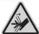
He BCTabnIte nIbui B pyxomi Detani KpohuTeHa. IaIbui MoKyTb 3aTHCHyTHCAI OTPHMATN 3HaayHi TpaBMn.
3601M2704.
3601M27OL.
3601M2708.
3601M27OB.
3601M27OK.
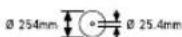
3BaKaJte Ha po3mipn nHbHoro
nonota. DiameTp OTbpy NOBHeH
nacyBaTHdo WnHdene 6e3 npomixky.
KIO noTpi6HO cKOpNCTaTcH
nepexIDHKOM, cnIDKyte 3a TM, IO6
po3mIPn nepexIDnKa BiINOBiJaH
TOBUNI NOHTHa NnHbHorO dNcKa i
diAmeTy OTbpy nHbHorO
NONOTA, a TAKOX DIaMeTp WnHdEe.
RkIO MOJIInBO, BnKOpNCTOByTe
nepexIDHK, JKN NoCTaayEBcra
pa3OM 3 NnJIbHM NOnOTHom.
DiameTp NnJIbHorO NOToTHa MaE
BiINOBiATNa DAHN HA CHMBONI.
3601M2700.
3601M2703.
3601M2706.
3601M2707.
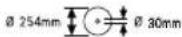
Iiuc TpaHcnpTyBaHHneKtpoiHCTpyMeHTa TpMaTecTinbKn 3a ci N03haeHmicu(3aunnHnDny pyk).
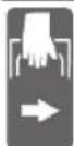
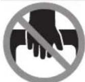
HikonHe nepehocbTe enekTpoiHCTpyMeHT 3a pyKoRTky Ha KPOHtHi.
CNMBONH TaixHE 3haueHHA

Ypa3iBepTnKaIbHnxKytIB p03nIOBaHHHeo6xIdHO nepeCyHyTn abo 3OBcim 3HATN IIBn a6o npabn noobkByaay npopHOI nHaHKn.

3aTHCKHa pyKoRTKa BiDnyuIeHa: MoKJIbICtB HaCTPOHOBaHHa BEpTKaJIbHx KyTIB pO3NIIIOBAHHa.
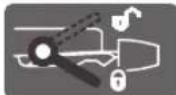
3aTnCKHa pyKoRTka 3aTnCHeHa: HAcTPOeHE Ha KPOHHTeHi 3HaueHHBepTKaIbHO Kya Po3nnIOBaHH36epiraTbcra.
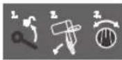
Ioka3ye nocniIOBHiCTb di npn BCTaHOBHeHHi BeptNKaJIbHOrO KYTa PO3NIIHOBaHH.
- BiDnyctitb 3aTnCKHy pyKoRTky
2.3nerka HaxnniB KPOHHTN libopyu
3.BctaHOBtHaNoBOPoTHi pyuichi Heo6xidHn diana3OH BeptnKaIbHorO KyTa po3nHIOBaHH
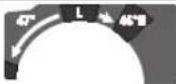
BctaHOBHeHHHa NOBOpTHi pyu iDiana3OHIB BepTKKaIbHOrO KyTa p03NIOBAHHA:

HaxnneHHHnnnHbHO nONoTHa nibopyy (45^ 0^)

HaxnneHHnnnBHO nnoTH npabopyu (0^ 45^)
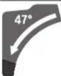
Becb diaana3oh haxnny KpoHwTeHa (-47°...+47°)

HnHaCTPOKOBHHHOBINbHNrOpN3OHTaIbHNx KYTB PO3NIIOBAHHcTIn MaE BinbNo nepecyBaTHcA60npctpi Po3IoKYBaHHKaTMaec6yTH 3a6NOKOBAHn:

-NotTnHtB Baxjin Ta OndHouacHo npntncHtB npntcpi po36noKyBaHHa KYa B nepeHni qactnHi DoHNs3y ②.
IHCtpymENTH,Notpi6hi DoaTkoBO Do 06cary NoCTABK:
Xpectoioi6ha BHKpytka
-ДинhamOMetPnHnKIOU(po3Mip:8MM)
272|YkpaHcbKa
- KInbueBn, BnIKOBn a6o TopeBn rAaKOBn KIOU (po3mip: 10 MM Ta 17 MM)
MOHTAK OKPemix Detanei
-ObepexHo BnMItb Bci DeTani 3ynapOBKn.
-3HimItb 3eneKtponpnpnady i 3 npnaand BcO ynakobky.
Mohtax pyuynkphiKcaui (DnB.man.a)
BkpyTb pyky fikcaii (11) y BiinobiHn OTBip Hd BaxKeIeM (12).
Ppeo3nHIOBAHHM 3aBxH MioH 3aTAYte pyky fikcaii (11).HaKHe PnNAbHn DnCK MoKe nepeKOCHNC B 3aROTOBUJI.
MOnTak 3aTnckHOI pyKoTkn dIy BInbHoro BCTaHOBneHH Kya Ta PO3NIIIOBaHH (BePTHKaJIbHoro) (INB.MaI.a)
MOnTAXy 3aTHCKHOI pyKoRTKn (13) BnKOpHCTOByte DoaHm MOtaxKn KOMnEeKT (TopueBn raiKOBn KIOU, raKy, 2 niknaDi wa6n).
-HaJIbTe OkpemI deTani y BkazAHIN NocnIOBHOCTi (BeNka niknaJa haaw6a, 3atckHa pyKoRTka, Mana niknaJaHaaw6a,raika) Ha p3b6OBn naneCb Ha eneKTpoHCTpyMeHTi.
-Дя Крацои nepedayi cnnpn 3aTaryBaHHI raKIN npocyHbTe DoaHn KInOu-WeCTnPaHHNk (30) Kpi3b OTBOPN Y TOPeBOMy KJIQUi.
MiHcO3aTnHtBraKy.
MoTAX NOOBOXYBaBbHOI dyXKn (DnB. Man. b)
-3HIMITb BiDCMOKTyBaIbHHaIaIaTep (35) WJIXOM BKNpyyBaHH HOrO 3 NaTpPy6Ka BKNJaaua TnpCn (36).
-BnДaJIbIb yIamKm 3aRToBKn Ta TnpCy.
-3HOBy HATaHHTb BIDCMOKTyBaIbHN aIaTep 7JXOM 3aKpyuBaHHn HOro Ha ntpy6ok BKNJa4a TnpCn, 06 BIn yBIIWOB B3aeyIeHHHa Hd 3aTHCKHM KINbcem NaTPy6Ka BKNJa4a TnpCn.
3aima HnHbHoro dncka (nVB. Man. e1-e4)
Ppe6ydb-akmmMaHinyiaum3 enektpponpnaDOMBHTaRHTbWtencenb3po3eKN.
MOnTaKy HnHbHOrKaO6oB'3KOB B4raTe 3axChi pyKaBuCi. TopKaHHI O nHbHorO DnCKa Hece Bco6i He6e3neky nopaeHHJ.
BnKOpHCTOByTe NHee NnIaIbHI DnCKN, DOnyCTMa MaKcMmaIbHa WbNkICtB AKNX BnE, HIX KInbKICTb o6eptIB BaWOrO eNeKtpponpnaNy npn pOboti Ha xOnocToMy xOdi.
BukopncToByTe Nnne PnnaIbHi DnCKN, 0o BiNoBiaOt bXapakTepcntKam, 3a3NaueHm B ci nHctpykui, nepebipehi 3a EN 847-1 Ta MaOtB BiNobiHe MapKipyBaHH.
BukopncToByte nIe nnIyIbHI dNcK, 10 pekOMHDoBaHi Bnpo6hKom eIeKtpoiHCTpyMeHTy Ta npDAtHi dIaOBp6nIOBaHO MaTePiaNy. Ce nonepeJxye neperpiBaHHa 3y6uB iN qac po3nnIOBaHH.
Demontax nnnnblhoro dNcKa
BctaHObitbeeKtpoiHcTpymeHTbpo6oue noOKeHHA.
-Biinyctitb qikcyuynr TBHt (37) KIOUcEM WecTHrpaHHNKOM (6 MM) (30), 106 KOPOMNCNO (38) BIlbHO 3BVCANO BHN3.
-BiDnycitb KpinnblHHn TBnHT (39)(npn6n.Ha 2 o6eptn) 3aONOMORIOKIIOua-WeCTHrpAHNka(4MM)(30). TnHT He Tpe6ba BnKPuyBaN NOBHCIO.
-BiinycttB kpiINbHn rBNHT (40)(np6n. Ha 6 o6epTIB) 3a DOnOMOIO KIOUa-WeCTnRPAHHNka (4 MM) (30). TBNHT He Tpe6a BHKpyyBaTH NOBHCIO.
-BiTtRHTb3axHCHN uNTOK(41)BIDKpINMbHO rBNHTa (40) BnpeIdoHN3y.
-BiXnIbMaTHNKOB3axHCHN KOxy(6)Ha3aI yTPMMyTe MaTHNKOB3axHCHN KOxyyUbomy nOxehHi.
HaIbTe KOpMnCNO (38) OTBOPOM HaKpINHbHn TBnHT (40). 3aBAnu My MaTHNKOBn 3axCNH KOxy NiTPhMyETbCny BIKPHTOMy NIOKeHHi.
- NobeptaIte TBnH3 BHyTpiiHIM WeCTNRpaHHKOM (43) 3a DONOMOIO KJIHOyA-WeCTNRpaHHKa (6 MM) (30)i OJHOaCHO HAtNcKaIe HaΦiKcATOp WnHdEra (42), POKN BiH He yBiIeY 3aueHneHH.
-TPMaIe HATNCHYTM fIKcTOp WnHdEa (42)i BHKpyITb TBHT 3 BHYTIWHIM WeCTHRpaHHKOM (43) 3a CTpiKIO IO rOHNHHka (niba p3b!).
-3HIMtB 3aTnCKHHnФlaHeIb (44).
-3HIMiTbIIJIaJIbHeNoIOTHO(34).
MONTAX NINNABHOI DnCKA
PiicMOHTaxy CnIDKyIte 3a THM,IO6 HAprrmOK piaHHN 3y6IB (ctpinka Ha nHnHbHomy dNcKy) 3irABc3 HAprrkOM cTpiKN Ha 3axnChomy Koxyci!
3a noTpe6n ouHCTIb nepeD BCTaHOBNEHHM BcI DeTani, 0o 6ydyTb MOHTyBaTHCra.
-HaHbTe HOBe nIJIbHe IONOTHO HA BHyTpIiHi 3aTnCKHHΦNaHeu (45).
-NotaTe 3aTHckHnФnaHeCb (44) iBkpyITb rBNHT 3 BHYTpIWHM WcETnRpaHHNKOM (43).HaTNCtIb φiKcatop IINHdEe (42),uO6 Bin yBIWOB B3aueNneHH,ia 3aTARHITb TBnHT 3 BHYTpIWHM WcETnRpaHHNKOM IpOTN CTpiKNrOJHHNKA.
-3HIMITb KOPOMnCNo (38) 3KpINMbHO rBnHTa (40)i 3HOBy ONyCTtB MaTHNKOBn 3axCHNKOxyx (6).
-Писунгье зхионицИТOK(41)ЗHOБУпд КрINьнн ГИNT(40).
-3HOBy Tyro 3aTARHITb KpINnBHI rBNHTH (40)i (39).
- BctaHOBtB KOpOMnCNo (38) B NOaTkoBe noLoKeHHa 3HOBy 3aTgHtB BiD pyKn fikcyuOni TBnHT (37) KInOuyEMIeCTnRpaHHKOM (6 MM) (30).
Pobota
Peped6ydb-RAHMMAHInyraiImN3 eneKtpponpnaIOM BHTaRHiB wTeNCenb 3 po3ETKn.
TpaHcnpTHm fikcatop (nB.MaA)
TpaHcnpTHn fikcatop (26) nonerwye opyduBaHH eneKtpoiHCTpymENTOM iD qac noro TpaHcnpTyBaHHdo MICaeknnyataa.
Bidnyckannnphiikcaqii (po6ooy noonoxeHHa)
-3nerka npTnCHITb KPOHHTeIN BHN3 3a pykoTky (23) (3),IO6 3HrTH HabaHTaxeHH 3 TpaHCnOpTHORO fikcatopa (26).
-BNTHHTbTpaHCnOpTHmΦICatOP(26)doKINHA3OBHI.
-Повиьноидимimits Кронштейн (23)dooropn.
274|yKpaHcbka
ΦikcaiaeneKtponpnaNy (nonoKeHHa TpaHcnpTyBaHa)
-BiTtRHTb KPOHHTeHH (23)do ynpy Ha3a i 3aΦikcyte HoroB Ucbomy NonoKeHHI.
-OnyckaTe KPOHtEIN, NOKn TpaHCnOpTHN fikcAtop (26) He MoKHa 6yde NOBHCIO TBNCHTN BCEpeDHy.
Iiwi BkaizBKN: TpaHcnpTyBaHH
Φikcaizy kpoHHTeHa
Mexahi3M KOB3aHHKPOHHTeHa (23) MOXHa 3aΦiKCyBaTn 3a DOnOMoHO 3aTHCKHOrO BaeJe (2). PpN UbOMy MOxJIbI dBa NIOJOKeHH KPOHHTeHa:
-KPOHHTeHH BiDcyHyTn Ha3aI Do yNopy (JITTOPUOBAHNA)
-KPOHHTENIITARHYTNBNEpeDIOynpOy(KOMNaKTHe NOLOXEHNDAITPahCnOpTyBaHH)
PiIroTobKa do po6oTH
DonyctHMI p03MIPN 3aRTOBKN
MaKcHmAbHI 3aTOrTOBKN:
| Горозонтailingный КУТ po3плковаянna | Вернкailingный КУТ po3плковаянna | Висotingaхшируна [MM] |
| 0° 0° | 80x306 | |
| 45° 0° | 80x216 | |
| 0° 45° (паворуч) | 54x296 | |
| 0° 45° (паворуч) | 30x296 | |
| 45° 45° (паворуч) | 54x208 | |
| 45° 45° (паворуч) | 30x208 |
Mihimalbhi 3arotOBKN (= BCi 3arotOBKN, kI MOxHa 3aTnCKyBaTH NiBOpyu Ta npaBOpyu BiD nIIyNbHO rNcKa 3a DOnOMoROO IOnaHOI cTp6uHH (19)): 145 x 306 MM (DoBXKHa x WnpHHa)
MaKc.rn6Ha npOnnIObAHNa (0^ / 0^) :100MM
P03nIIIOBaHna
Po3nHIOBAHH6e3topHOHTaIbHOro nepecyBaHH cynpota(TopuOBAH)(INB.Man.N)
-BiTnHITb KPOHHTeHH (23)doynopyHa3aI 3aΦikcyTe HOroBcOmyNIOJKeHHI.
IpekoHaTecB TOMy, 10o 6mexyBaA rnnbHn (25)do ynpO npNTCHyn BCEpeHy, aIOCTpyBaNbHn TBnHT (24) npnepcyBaHn KPOHtHe npoXoDnT bpe3 OTBip, He TopKaIOUcB 6mexyBaaA rnnbHn.
-3aTnCHiBb6pO6NIOBAHy 3aOrTOBky BiINOBiDHO do II po3MpIb.
-3a notpe6n BCTaHOBtB Heo6xIDH N Kyt po3nnIOBaHH (ropn30HTaBHN Ta/a6o BeptKanbHn).
- Ybimkhitb enektpoiHCTpymENT.
-Повильно onуctить Кронштейн (23) з руков (3).
-Po3nHIOte 6pO6NHObAHy 3aROTOBky 3 pIBHomipHOI NOdaueHO.
BmKHTb eNKTPOiHCTpMyeHt 3aueKaHe, NOKN HnIyJIbHE NIOIHO NOBHICTIO He 3yINHITbCra.
-Повиьно пдимит Кронштейн (23)Вcrop.
P03HIOBAHH 3 ROPN3OHTaIbHHM nepecyBaHHM cynpota (INB.Man.0)
D6pe trmaTe pykoTky nepeyBimKHeHHn nnKn i nd qac BcBoO npoccy po3nnIOBaHH. nIq ac po3nnIOBAHH KOthpOboAHO nepeCybaHTeH. 3BaXaOHu HaHa3BnuAHy MaHEBpeHCTb KPOHTeHa, MHTb HeyBaXHOCTMOKe pN3BecTu DO cepNo3HN TpaBM.
-Po36nokyTe KPOHTeHH (23).PiTARHyBmTa BiCyHyBmKPOHTeHH (23),NepeBipTe,CHI rTOBm yBeCb MExaHI3M KOB3aHHdo po60TH.
-3aTnCHiB 6b0p6NIOBAHy 3aROTOBky BiINOBiINO do II po3MpipB.
-3a notpe6n BCTaHOBITb Heo6xIDHm KyT po3nHIOBaHHa (roPn30HTaBHm Ta/a6o BeptKanbHm).
-BiCyhBTe KPOHtEHN (23) 3a pyKoAry (3) BiynpHOI nHaHKN (8) HAcTIbKN, IIO6 NnJIbHe NoIOTHO ONHHIOcpepe3aTOBKOIO.
YbIMKHTb eNEKTpOIHCTpyMeH.
- NobinbHO onycttb KpOHTeHH (23) 3a pykoTky (3).
-Tepe npntncitb kpoHwteH B HapmkyynopHOI nHaHKn (23)8 Ta po3nnrTe 3aTOrTOBky 3 pIBHomipHOIO NOaHeo.
-BMHKHtB eENKTOPIOHCTPymeHT i3aueKaIte, nOKN HINJIbHe NOJIOTHO NOBHICTQ 3YINHHTcA.
-Повильно пidимп Кронштейн (23)Вcrop.
HactpoIOBAAHO6MEXyBaayrIN6HH(BnNIOBAHH na3IB)(INB.Ma.N.Q)
06mexyBaTuH6nHHeo6xJHo nepeHaauTyBaTH, Raio Bn 36npaTeCb BnHnIOBAtu Na3n abo BnKOpHCTOByBaTH nctaHuiHn ynop.
-Поверптб obмжува ngнбин (25) Na3OBH.
-NoBepHItb KPOHHTeHH (23) 3a pyKoRTky (3) B nOtpi6He nONOXeHH.
-BiDpyrinyIeIOCTpyBaIbHnTBAHT(24)TaK,IO6NOrO KIneB TopkABcO6MeJyBaVa TIN6HHN (25).
-Повиьно пдимить Кронштейн (23)Догор.
Oc06nBi3arotOBKn
106po3nnIOBAtn BnHryThn a6o KpyTmN MaTepiA, Tpe6a OcO6IINHM YNHOM 3aΦiKCyBatn Ioro, 106B Bin He COBaBC. Ha liHH po3nnIOBaHH He NOBHHo 6bTy IINH MIX o6pO6IOBaHHM MaTepiAion, ynpHOIO pHaHKOIO i CTONOM.
3a Heo6xjHicTIO BnroTyIe CneuaJIbHe KpInIIeHHA.
06po6ka npophiinbHH peHOK
PpOΦiBHi peKm MoXHa 06pO6nTn Dboma CnOco6amH:
HactpoBoHHa (IMB.MaI.T2)
-3aTaryte a6o BiDnyckaTepepyriOBaBHNrBHT(58) 3aDOnOMOroIO DnHAMOMeTpHuHO rAkoBOrKO KIOUa (8MM)doTHNip,POKNneue KYTOBOKANl6py He6yede NO Bci DOBkHI 36iraTnc3 NnIJIbHM DNCKOM.
-3HOBy Tyro 3aTnHiTb 3aTnCKHy pyKoRtKy (13).
Aki nia 3aikHHeHH HaCTPOIOBaHH iINKaTOpn KytA (28) i (21) 6ydyb 3haxoOnTcH He B ONDHy NiHIO 3 no3HaKAMN 45^ uKann (27), cnoatky pea nepeBipte HAcTPOIKy dIe BepTKaJIbHOrO KYta p03nIIIOBAHH O' i INKaTOpn KytA. Iicra yoro ue pa3 nobToPi bHaCToPoy k dy BepTKaJIbHOrO KYta po3nnIOBAHH 45^
BhpibHIOBAHHH KAN H Tn rOpH3OHTaBHNX KytIB po3nnIOBAHH
BcTaHObit enekTpponpinnad Bpo6oNe noJooHenH.
- NoBepHbTcIn (33)do HaciuKn (14) 0^ .BaKInb (12) NOBHeH BiDyTHo yBiHTn B 3aueIeHHra B Haciu.
TepeBipka (DHB. Man. U1)
BCTaHOBITkyTObH Kani6p Ha 90° i NOKlaITb HOrO MIX yNOpHOI PAnHKOIO (8) i INJIbHIM DnCKOM (34) HA CTIN (33).
Плесу КТОВО KANI6py NOBHHNO NO BCIN DOBXH N36iRaTnC3 ПИЯьнIMДNCKOM(34).
-3HOBy 3aTgHITb TBHHTN.
Aki no nla hactpoobha HnkaTOp kyta (51) He 6yde 3biratnc 3 no3aHauko O'Ha wkani (31), 3a donomoroo xpectoio6hoBHKpyTK BiNycttB FBHT (60) Ta BnpiBHeIe IHnKaTOp kyta 3a no3aHauko O'.
PerynoBaHHn CnHn 3aTHCHeHHaTHcKHO Baxen (13) (mB.Man.V)
Cnny 3aTNCHEHHa3aTHCKHOro BaXeJIa (13) MoXHa peYnHOBAtN.
IpebeBipka
Cnla3aTncHeHH 3aTHCKHOI pyKoRTKn Mae 6ytN DOCTaTHbOIO dNTO,IO6 KPOHHTeIN HADHI HO YTPMByBaBCB CBOEMy NOLOKeHHI npN 6yDb-RAKOmy BEPTHKaJIbHOMY KyTI pO3NIIOBaHH.
HactpoobHH
-BiDnyctTb 3aTnckHy pykoAky (13).
-NoBepHtBperyIIOBaIbHHrTBnHT(61)3aDOnOMoHO TOpueBOrOraIKOBoroKIOOa(17 MM)npOTnCTpiNKI rOHHNkA,IO63MeHUnTnCnNy3aTNCHeHn,A603a CTpiKOHO rOHHNkA,IO63bUbHTn CnNy 3aTNCHeHn.
BCTaHOIBtB BePTnKanbHn Kyt piaHHa,3HOBy 3aTARHITb 3aTNCKHy pyKoHTKy (13) i nepeBipTe, uN DoCraHyTa Heo6xIDHa Cnna 3aTNCHeHH.
TpaHcnpotybaHHa (nB.MaW)
Nepu Hix TpaHcnpTyBaTH eneKtpoiHCTpyMeHT, Tpe6a BHKoHaTn TaKi Dii:
-BiTnHITb KPOHTeHH (23) Do ynpy Haazd i zafikcyte Horo B cboMy noloxehHI (DINB. KcYBaHHKPOHHTeHa, ctop. 23).
-NepekoHaTeCBA ToM,IOoO6MeKyBaHrN6Hn (25)do ynpny npTHCHTuBCEpeHNy,aIOCTpyBaIbHn TBHn (24) npnpecyBaHHkPOHTeHa nPoXoHtBupe3 OTBip,HE TOPKaOHcB oMeKyBaHa rN6Hn.
-OnyckaTe KPOHTeH, NOKI TpaHCnOpTHNIΦiKcatop (26) He MoXHa 6yJe NOBHiCTO BTNCHTN BCEpeDHy.
-NoCyHbTe NoOBKByBaIbHy DyKky (16) Do ynopy B HaprMky ueHTpy CTony.
- BcTaHOBtB BePTnKaJIbHm KYT pO3nHIOBaHHa Ho 0°i 3aTNCIb 3aTNCHy pyKoRTy (13).
-Поверніт bст (33)do ynopy nibopy Ta 3atraynt pyky fiikcaii (11).
-3B'XKtB WHyp XHbEnHHa 3a DOnOMoROO CTpiKnIINnyuK (62).
-3HimItB BCE npnndra,Ke He MOxHa MiUHO MOHTyBaTH Ha eNEKtpoiHCTpyMeHTI.
-3aMOKJIHBOCTIpeHOCbTe NIIJIbHI NOJIOtha,AKMIMBHe KOPNCyTEcA,B3aKpTNXEMHOCTAX.
-PepeHocbte enEeKtpoiHcTpymeHTa3aIHHnHN Dpyk (17),po3aioBahi 360ky Ha cToni.
ДлгТранспортуванье endKtpoHCTpyMeHTa BHKOPNCTOByTe TINbKn pNCHOTcyBaHnДлгТранспортуваньЯ Ta Hi BЯKOMy pa3i He BHKOPNCTOByTe dAnZbOro 3axHChi npNCTpoI, KPOHHTeH (23) a60 pyKoTky (3).
Texhuihe 06cnyrobyBaHHaicepBic
Texhihe 06cnyroByaHH i ouhenceHH
Ipeep6ydb-RAHMMAHInyraicIMN3 enektpponpnaJOM BHTaRHiB wTeNCb 3 po3ETKn.
Дляякioi 6e3neuhoi pobotn trmaite enektpponpnaia bENTnnaui OTbOpB uchctoti.
Akyto Tpe6a NOMIHnPiEeHyBaHbNn Ka6eB,ue Tpe6a pO6HTHaΦipMi Bosch a6o B cepBicHi MaICTepHI dIneKtPOINCTpyMeHrBosch,io6yHNKHyTn He63neK.
MaTHKOBn 3axncn KOKyX Ma 3aBKn BInbHO nepeCyBaTnC i camOtiHo 3akPnBaTnc. 3iie npuHn 3aBKn TpMaTe 3OHy HabKONo MaTHKOBOro 3axCHORo KOxyxA BHTOTI.
IicnKoKHOi pO6Ooi onepaui 3dyBaIte nnn i ctpyKky CTNCHEHIM NOBITpM a60 3mitaTe ix Lio
-Perynphopno npoounaTe KOB3Hn poNk (20) Ta KPOHHTeH (23).
Ppnaa
www.bosch-pt.com/serviceaddresses
Ytunizaia
Enektponpnpnadi npnndi iynakOBky tpe6a 3daBAtnHa ekoloriuho nCtuy nobTophy nepepo6ky.
He BnKnaTe eneKtpoiHcTpymEnB nobyTOBe cmTTI
Пишдя Крайс:
BIDIOBIDHO IO CBPoneCboKoi DnpeKTHBN 2012/19/EU
IIOO BIDINpaBOaHNX eNEKTPuHNX i ENEKTPoHHNX
pnpadib i II nepeTbOpEHn BAuioHaJIbHe 3aKOHODABCTBO
He npdathIO BxNBaHHN eNEKTPoIHCTpyMeHTn Tpe6a
3bnpaN OKpemO i3daBAtn Ha ekONOrIHo Yncty
pekynepaioio.
PnHnpaBnblHi ytni3auiB iDnpaBObaHI eektpnuH ta eNEKTPOHNI pnilaM MoKyTB MaTH WkIDINBn BnNB H aHbKOJIuNHe cepeOBoNue Ta 3DopOB'AnODHH uepe3 MOKNBy HAABHnicr Hebe3neuHx peoBHn.
Ka3ak
Eypa3nna 3KoHOMnKaIbIK OdaftbHa (KeJeH OdaftbHa) Mywe MemLeKeTtep aymafbIHda KOnDaHbIaNbl
HdiPywiin HcHIM yiwin Kapactbipfah naaanaHy KxKaTapbHbN Kypambln aNaIaHaNy XeHHeiOCbl HCKaybnk,cohBmeh bipre KocbImanap da bony MyMkiH.
Caikekti pa:ay JaiNbI aKnapaT KocbIMwaJa 6ap.
HImDi eHdipreH MemKeT TypaIb aKnapat eHimHiKopnycbihda XHe KocbIMwada KepcetinreH.
HdiipinreH mep3imi HyckaynbK Myka6acbHbH coHfB 6etihde KepcetinreH.
HmnpTepeKaTbIcTb6aNaHbCaknapaOHIM KaTAMacbHda KepcetinreH.
Ehimi naianda hy Mep3iMi
HMHHHKbI3MeTetyMep3i7KbI.HTdpinreHmep3imHe6actan(HHPy KYHI 3aybIT taKaTHwacBHJa Ka3BnFAH)ICTeNe5KbINCaKaTaHaHHaCOH,EHIMDi TEKcepyCi (cepNtIK TeKcepy) naDAnAHy CbIHbIMaDbI.
Kepcetiren Kbl3met ety Mep3i TYtbiHyu bI aTaIbI HcykaynbIKbIH TaanTapbH OpbHaFaJKaFdaJaFaHa Jkapambl60nabl.
Ictehyce6entepinHt3imi
KENyIKbIH yIbIcA,naIdaIaNbHaB13
KaTbI dpiIn Ke3iHne naIdaIaNb6aHbI3
-TOKcBmbl6y3bJFaH Hemece OKuaynaycb3 60nca, naDanaHaB3
-ehim KopnycbHAn TikeNe TytH WbIKca, naIaIaN6aHbI3
TainanahyubihbMymkH kateniktepi
TytKacbMeH Kopnycbl 6y3bnFaH 60nca, eHIMni naDanaHa6aHb3
-kahyiH-waibHKe3IHDe cbiPTa naJdaHaBbI3
Kopnyc iwihe cy Kipce Kypbifhbl Kocybl 60MaHb3
Uekri Kyi 6enrinepi
-TOKCbMbHbIHTO3yblHEMeCe3aKbIMDaHybl
-0HIM KOpNcBbH3aKbIMdanybl
Kb3MET Kepcety Typi MeH xinirl
-0p naaanahydaoncoHimTaaanay ycbihnaabbl.
CaRTay
KpyrakkepecaKayek
JXOFAPbI TemnepaTypa Ke3iHeH XaHe KYN CaynepePiHi, acepiH e anbc caKtay KepeK
- cakay Ke3iHne TemnepaTypaBHH KeHET aybITkyBHAn Kopray KepeK
-opaMacbi caKay MyMKiH eMec
- cakay wapTApbl typaBkocbIMwa aknapaTanyuH MEMCT 15150-69 (wapt 1) KkaTbH kapaHb3
- +5-EN+40°C-Ka DeIN TMNepaTpyacbHda KOIMada ΘHdipyHHKANTAMacbHda CaKaTaHb3. CalbCTbIPMaBblBnFaDblBk80%-DaH acnaybl Tnic.
TacbImaay
TacbImaIay KeiHne OHIMJI KynATyFA XeHe Ke3 KeIReH MExAHKnAblk bknan etye KaTah TblbIM CaBHaDbl
-6ocaty/xykTey Ke3iHne NaKeTI KbICaTBH MaunHaapn naDanaHyfpa KyKcat 6epimmei
-TacbImaJay wapTAPbI tanaTAPbIH MEMCT 15150-69 (5wapT)KxKaTbIH OKbIHb3
-KopwaHApTaemnepaTpacbI-50°C-tan+50°C-Ka DeHHTacbMaJday pyKcatetinreH.CaBicbIpMaJIb BInFaJbIbIK 100%-daH acnyai Tnic.
Kayinci3ik HycKaynapbI
3neKtp KypanapbI ywiH Xannbl Kayinci3dk HycKaynapbl
ECKEPTY
OcbI 3neKtp KypaIbHbHn
XHHaftbHdafte eceptynepdi,
Hcyaynapdbcypertepjxane cnaTamaIapdb 0kblb3.BapbIKTexHKnabIK KayinciDik HcyaybIKTapbHOpbHdAmay TOKtbHcoFyiba,optXaHe/ Hemece aybp KapakatHaNapfa anBn Kenyi MymkiH.
BonaawkXymbctap yuH Kayinci3ik HycKaynbikTapbI Me h ckeptnenepe caKtan KOnb1b13.
Kayinciik HcyckaynbkTapbHda naaandaHbnFaH 3neKtp Kypan ataybHbH KeniDeH Kyat anaTbH 3neKTP KypandpbHa (Keniik KaBenMeHe) Xe He AKKyMnTOpDnEH Kyat anaTbH 3neKtp KypandapbHa (Keniik KaBenKoK) KaTbcB6ap.
XymbicophbHbHKayinci3diri
XymbicopbihTa3aXeHxapbikycTahbi.1actaHaHAn XeHkapaHbfXainapdaCtciOKfHanap6onyblMYMKIH
3NeKtp KpybIYbcih XkapblaTbIH ATMocpepa naDanaH6aHb3, MbICabI, XaHaTbIH cyBbIKtbK, ra3 Hemece wan 6ap 6onFaHda.3NeKtp Kypal YWKbIHapdbI XacaNbI, an onap waH Hemece 6ynapdbI XaHdbipyMymKiH.
Bananap men 6akbinaywbnapdp3neKtp KypanbHAnbc yctah3. Andaynap 6akbinay XofanybiHa anbin Kenyi MYMKIN.
Kabik Tpymbicik KaFdaHapda, KOMMepnIbIK aMaKTapJaKaHe KofaMbIK XepNepde, 3HHbI KHe Kayinti Ehdipictik paktopnap KOK KIIeKTP TybHybI 6ap eHidipictik aMaKtaPbHa DxMyBic icTey yihin apHaJIraH.
3nekt kayinciäiri
3neKtp aHbIpnapb po3eTkafca ca6oynbTic. AibpIbEwkaaHewkaHdA Tepi3de 03reptneH3. Xepre KocBIFAH 3neKtp KypanapbIMeH aadTep aHbIpnapbHn PAnDanaH6aHbI3. 03reTpInmereH aHbIpap MeH c9KeC po3eTKanap 3neKtp TybIKTaIyBiHbIH KayinIH TEMeHNTeTei.
Ky6bipnap,paHaTopnap,nnHtanap Meh cybitkbiwTap CnKtbiXepre Kocbinfah 6TETepre Tmehi3. Dehehi
Kepre KocbIraH bOnca KOrapbToK cOy Kayini naHa 6onadbl.
3NeKtp Kypanapdbj KaH6bpJa HEmece bINFaIbI Kopwayda naaDaHa6aHbI. 3NeKtp KypanbHa KipreH cy ToK,coFy Kayinih KofapblataBbl.
Kabebdi Tnicti 60nmaHan pette naaandaHaB13. Kaebdi 3neKtp KypanbH Tacy,KeTepy Hemece TokraH WbIFapy yWIn naDanaHa6Ba13. Kaebdi bICTbIKbIK, MaI, eTKip Kbpnap XHe XblXbImaBl 6nweKtepen anbc yctamaHb13. 3akbIMdaJfAH Hemece 6bITcBIn Ketkeh Kaebb TokcoY KayinIH KOrapbInatabl.
3NeKtp KypaBnH cbiptTna naDanaHaHaDa cbiptKbI Xaainap ywiH cai Ka6ebdi naDanaHbIHb13. CbiPTa naDanaHyFa JapaMdbi Ka6ebdi naDanaHy TOK cOy F KayinH TeMeHdeNi
Erep 3neKtp KypanbH bINFaNdbI Keppe naDanaHy Kepek 60nca, OHda KopFaNbH Owipy Kypbnfbicbl (RCD) apKbInbI KOPFaNFAH TOK Kenicih naDanaHbIB13. RCD naDanaHy TOK cOy KayinIH TMeHdTeJI.
KeKayinci3ik
3NeKtp KpaIbI naIaIaNHyda 6aBn 60bnHbI3, XyMbIcIbHbI3dbI 6akblNaHbI 3xHe npacATbI naIaIaNbHbI3.3NeKtp KpaIbI waPawafn Ke3De Hemece eciptKI, anKOroNb Hemece aep eTKeH Ke3De naIaIaN6aHbI3.3NeKtp KpaIbIH naIaIaNHy Ke3IHne aHcbI3dbIK aybp Jxke JkaPaKaTTHaYfa anBn Kenyi MymkiH.
JKeKe KOPraTbH Jx6dbKTapbl NaDanaHbHb3. 2PdAaBIM Ke3 KOPraHbCbH TaFbHb3. HaMaCKacbl, cbprHaBtBn KayinciAdik aR KInMepi, WneM HeMece ctY KOPraHbIITapbl CNKKTbl KOPraBbI Xa6dbkTapbl TlCTI Xa4dAnnapDa KOJaHbIN XeKe XapaKaTaHynapDbk KeMeTeJI.
Ke3eKcKcKocbIydbH anDbH any. Tok Ke3iHe KHe/Hemec6aTapeepnap KNaHaBHa KocyaH aNbH, KypaNbI KeTepy HEmec TacydAanDbH eipriwEiwKyIe 6onybHa Ke3XeKtizH3.3NeKtp KypaH CayCaKTB1 eWipriuke KoBIn Tacy Hemece KockblbKocybl3neKTP KypaBnH TOKa Kocy cTci3 OKFaFa aNbI Kenyi MYMkiH.
3NeKtp KypalbH KocyaH anbH KeRr H petTey cblHaCbH HeMece KITI aBn KObHbI3. 3NeKtp KypalbHbH aHAnaTbH 6eNirHne KaFraH KINT HeMece cblHa XeKe JapaKaTaHyra anbH Kenyi MymKIn.
Ken kyw icTeTneH3. OpaBIM Tnicti TaanbHni neH cnMaKaBtBnIKbI CaKaTbI3. Byn KytimereH KaDaainnpda 3eKtp KypanbH 6aKbnaHyh caKaTaNbl.
Thicti KIM KINH3. Boc KIM MeH OWeKeIePdi KINMeH3. WAsbHb3 6en KIMdePdi XbInXbImaBb 6eWekTepeH anbcYcTaHb3. Boc KIMep, aWeKeIeP HEmecE Y3bH WAs WxkbimAb6eWekTe apKbJIbTapblNybl MyMkiH.
ErepwHbIfapbnXHHayXa6bIbKTapbHaKocy Kypbnfbnapbl6epnireh6oNca,OndaonapKocynbl
282|Ka3aKa
6onybHa XHe TNicti pette KOndanybHa Ke3 KeTkiin3. WaH KInHayIa NaJaIaNy WaHa 6aIIaHbCTb 3nHdapBk EmeTei.
Acantrapbji Kni nai daa hbn jka cbsi 6inreHH coH macaipan KeTneKayinc3dk npnHnntepin enemoe TbipMaHbI. A6aCb3 apekET cekyHd iwiHne aybip kapaKaTTaHyra anBn Kenyi MymkiH.
HA3AP AYdAPbHbI3! 3heprnmeH x6dbkTaydbH TOblkTaHe XeKeene ToKtaTbNyblHEmece 3heprnmeH x6dbkTaydbI backapy Ti6berinH akaynahybI candaPbHaH 3neKtp KypaNbHbH jxmbcbHda Kiipic naJa 6onfah KaFdaJa, 6yfaTTMaFaHbIbHa Ka3XeTKi3In (6onfah KaFdaJa) 6abH, axbipatkbHbBbKn. (Owipy) KaNbHa KeTIpiH. Xeninik awahbI po3ekadaH sbIfapbHb3 Hemece anbl - canMaBl aKKymnTopDbIxbpatbHb3. Ocblapeket apKbblb6akbnAbaTbH kaTa icke Kocblnybl anDbH anacbl.
AtanmbiHnaiDanaHyKeHHderi HcckaynbkaCnkeC 6iniKti Kbi3MeTkePnep KypambHa 3neKtp KpaBnH pettey, MOHTaXdAy, KOJaDaHbCKa eHr3y JxHe OFaH Kb3MeT KepcTepeKETepIme TaHbc TynFaapan KaTaBl.
3NeKtp KypaBImeH KyMbIc icTeyre 18 Xacka TonFaH, TexHNKaIbIK CnAATTaMaHbI, NaIaNanHy KeHHderi HcyKaynbITbXHe Kayinci3ik epexenePi OKbin WbIKaH TynFaNapF pyKcat erinei.
Dehe, ceim Hemece akbn- on kabineTepi wekteyni Hemece taKipnb6eci meh 6inimi xetKinikci3 aamap onapdbH kayincidiri yih XayantbTyfahBn 6akblaybHa 6oMaca Hemece 3neKtp Kpaanb H naDanahy 6oBbHna Hyckay anmaFaH 6oJbIMdbi naDanaHbaybTnic.
3neKtp KypanapbH naindanyKahe KyTy
KypanbI aca kon kYkTeMeH3. KymbcIbHb3 yinXapaMbI 3NeKTP KypanbIH naJaHaNbHb3. KapaMdbI 3NeKTP KypaJIbIMeH KepeKTi KymbIC aMafBHaDyPbIC api ceHIMdi KymbIC icTeic3.
AkpapkblbDpybcEmc3neKtp Kypanbln naDanaH6aHbI. Kocyfa Hemece eWipyre 60mMaHTbH 3neKtp KypanblKayinti 60bln, OHblXeHDey KaKeT 60anaBl.
Ka6dbikapdb peTey, 6onwekTepih anMaCtbipy HEmece 3NEKTP KypanadpbH KOIMAFa KOAnDbHda, aahbkyat Ke3iHe AxxbipTaBbIb3 XaHe/Hemec EAKyMnTOpbI anMaIbI-canMaIbI 6oJc, Obl 3NEKTP KypanbHaH anbIn TactaH3. Byn caTbIK epeKeTI 3NEKTP KypandbH baiKaycbI3 KocbinybHa Konl 6epMeNdi.
PnndanbHmMaTbH 3neKtp Kypanapdb6anapanap KOJIxETneTIH XaIFA KObIHbI3. OcInapDb 6InMeHTH Hemece Ocbl eCKePTnepePi OKImafAH aamdpfa 6yn KypandbI NaHanaHyFa Kon6epMei3. T@kip6eci3 aamdap KOnbHa 3neKtp KypanapbKayinT 6oanaB
3neKtp KypanapbHm MeKepe-KapaKTapbH ykbntbkyTih. Ko3rMaMb6nweKTePdi Keeprici3icteyine XeHe Kentenin KanMabyHa, 6nweKTePdH
akaycbi3 Hemece 3aKbIMdaMaHaF 6OnybiHa, 3neKtp KypalibHb3 aKbIMdaMaHaBHa Ke3 JeTeKi3H3. 3aKbIMdaFaHb6nweKtepi 6ap Kypanbl NaJdanaHyDAn anDbH XeHJeH3. 3neKtp KypalapbHbIN Dpybc KytimMeYi Ka3aTaNbIM OKfApaFa ce6en 60bnXataBbl.
Keckiw acnantapdb otKip kane Ta3a kyide caTahb3. DypbckytinreHkane Keckiw knekepi etkip Keckiw acnantap a3 Kentenin, Kecineti 6etke OHai 6afblTana#.
3neKtp KypalbH, Xa6blkTapbl, anMaBc-CanMaBl acnantapblXeHeT.6.OCbHyckaynapfa ca nnaDanaHbIb3. CohBMEN KymbcI apTTapbImen opbHdAaTBH apeKeTepre HaapaydpbHb3.3neKtp KypalapbH apHaMafan XyMbICTapda naDanahy Kayinti.
Kontykanap Meh KapMay 6eTepin Kypfak, Ta3a XKeHe MaH MeH NaCTAH Ta3a YcTaHbI. CbIPraHaK KonTykanap MeH KapMay 6eTepi KyTINmereH XaFdaNapda ceHIMdi KOnDaHy MeH 6aKbInayFa KOn 6epMeNi.
Kb3MeT KepcTeY
3NeKtp KypaBbHa MaMaHbJxHcHcyWl TeK 6ipde KocanKbI 6nWeKtEpMeH KbI3Met Kepctyi Kepe. Byn 3NeKtp KypaBbHbH Kayinci3diH caTaNyblh KaMTamacbl3 etedi.
BypbIbTkapapa ywiin kayinci3ik HycKaynapbl
BypbIbIKapa aFauHemece aafw CnKbI eHIMepdi apanayFa aphanFA, onapdbI abpa3NBti kecy DeHreKeTepimen 6pyc, uib6bIK, were XeH T.6. CnKbTI Temip MATEpnaIapdbI apanayFa naIaIaNMyMKIN emec. A6pa3NBt apanaydafty uKbIHdap TeMeHri tipeyiIi, iunek Xehe 6bac4 bIeKTePdi KaHbIpaIbI.
Даындаимы усту ушin мимкинбога КбICьИТары naДаланынБИЗ.Даындаимы konmen yctacahb3,КOBIHbI3dbI apaДнckicineh kemihde 100 MM KaibkTBkTA yCTah3. Kbicy wih hemecce konmen yctay wih TBm KiWi 6oIweKTePJI kecy wih 6yn apabH naDanaH6anb3.Erep KolbIbI3 apaДnckicine TbIM JkaBH 6Ola,Диckire TIOJednBIFaTbH YIKBHaDapdAn HkapakatTuH Kayini Kofapbl 6onabI.
Даында мурактб 60ил tipeyi nen yctenre KbcibnybHemece tipenyi Kepek.Даында mahbl DnCKIRe XbIIKbITNaHb3 Hemece KOnMeH anapMaHb3. KbiclbMafanHemece XbIIKbImaJIb Daында manaJ Kofapbl XbIIaMbIKTa NaKtbpblN JapaKaTTaybl MymkiH.
ApaHdaaBHaDamaF6acbHb3.ApaHdaaBHaDamaHapTnAb3.Kecik icTey yuH apa6acbHKeTePIn,daBHdamaKofFabbcihAH KecneiOTKi3iH3,KoFaNTkBiIITbIcKeKocbHb3,apa6acbHtemeH6acbIn,apahbdaBHaDamaF6acbHb3.TaptbnapanayAPA dNckiciH daBHdama yCTHe bIFapbl,NNCKHI onepatopra Kapai NaTbpybl MymkiH.
KoIbIbI3dbI ewkaaH apa dNckicih anbHnHa HEmece apTbHda Kecy cbIbFbHa KOImaHb3. Baca KaONMeH daBbHdAmHa yCTay, MbCaJIb, daBbHdMaHbI apa dNckiciH OH XaFbHda cO1 KOImeH yCTay HEmece tepici ete kayinti.
EwkaaH Konblb3dI aafx KooKanapBn Hemece 6aca ce6enten dNcki aHahbn TpyfHa npa apnckicine 100 MM-DeH XaKbH Tipeyiu apKacbHa anapMaHb3. AinHaBn TpyFaH apaHbIH XaKbIHbIfbl Dypbc aIKbIHdaJIMa ci3 KaTbI KapaKaTTaHybl3 MymkIH.
Kecyeh andbih daibihdamahbltekcepi3.Erep Daibihama KncaibTbIFAH HeMece Deopmaunahfah 60nca,ohbi cbiptkbl KncaibTbIFAH XAFbIMe Tipeyiuke KbcibHb3. 3paabim Kecik 60bdaaBHdama,TipeiyixKHe ycten apacbHaapaBik 60mMaybHaKe3 KeTKi3iH3. BypbifAH HeMece Kncaifan DaibHdAmapwnpan, XblXbIn He aHbIn Typfah apaDnckicih Kbcbin Kanbyi MymkiH.DaiBHdamaWere Hemece 6acka 6erde DeHeIep 6oMaybTNC.
Ycten6apnbkacnantap,araawxohkanapbl.6.6oc 60mafahwa apahb naDanaH6aht3.Kiui cbiHbiktap Hemece 6oc aawa 6oienektepi He baca HbcHaDap aHaBbIn TypFaH nckire Tnce, Onap Xofapbl XblMaBkneH naKtbIpbblMmKIH.
Bip yaKbTTa Tk 6ip FaHa daBihDamaHb apanaHb3. KHNan KOyBnFaH 6ipHeWe daBihDamaNap dypbic KbcjIMa He 6ekTINMe apanay KeiHne DnCKHI KbcCybl Hemece XbJNcybl MymKiH.
PnDnAnhyan anBbH 6pybIwTbIK apaHbH Teric, TypaKbI Kymblc aHaMaFbHbA 6eKtinyin Hemece opHaJnactbipbIyBH KaMTamacb3 etIH3.Teric XHe TypaKbI Kymblc aHaMaFbI 6pybIwTbIK apaHbH KIMMbIJaN KeTy KayinH KEMITEi.
Kymbcbih3dbxocnapaHb3. EHC Hemece Ke6ey 6ypbmbihinnapameptipn 03reptkehi3de, pettenetih tipeiydaibHdamaHbI yctayfa dypbc pettenrenih xhe ndckhi Hemece Kopray kyeine TmeyiHe K93 XETk3iH3. AcanTb "KOCY"an anDhIn xhe yctennde daBHdama 6oMaraHaAPA dnckicin 6ytih cmynaHbIK cekikTe hEK3iIN,Keepri 6oMbayHa xHe tipeiyk Cecimmeyine Ke3 keTkiH3.
YcTeENH yNKeH daBbIHdAManap yWih YcTei KeHeHTKIWI, apaay caHdaJIb, T.6. cHKTbI KEmekwi acnantap apKbIbI dypbcI yCtaydbI KaMTaMaCbI3 etIH3. bpybIbIKAPA yCTeINHEy3BH HeMece KeH daBbIHdAManap ceHIMdi yCTaIMaca aydpblbMyMKIH. Erep kecinren 6oNeK Hemece daBbIHdAmaydpblca, on TemeHri TIpeyiUti KTepeyi Hemece aHaBbIn TyPfAH NCKIMEH NaKbIPbIbI MyMKIH.
YcTeN KeHeiKtIiHemeCe KocBIMua Tipeyi OphBHa 6aKa aAaMbI naJaIaNb6aHbI3. DaBHdMa TypaKTbI 6eKITINMeCE NcKi KbCblNybi HeMece DaBHdMa Kecy Ke3iHJe KblXbI, ci3JI HeKeMeKwH3JI aiHaBIn TypFaH dNCKIRE KaBbIHDaTybl MyMKH.
KecinreH 6eK TpybIn KANMaybHemece aHaBbIn TypfApa DnckicHe 6acblmMaybTnic. WKeTeReH 6oCa,MbcaIbY3bHbIK WKeTeynepi apkblb,KeCinreH 6eK DnCKIRE KbcblbN KaTbNaKTbPbIyMymKiH.
Mb6HHeMece Ky6bip CnKtBdOMaNak MaTePhanap yuih epaibim Kbickhi HeMece 6ekitkiwi naDanaHbHb3. Lb6bIKTap kecinreHHe coH DOMaIaN KeTyI MymKiH, MyHa DnCKi TICTen DaBHMaHbI KOblHb36eH 6ipre DnCKire TapTybI MymKiH.
DaiBihdAmafaTHIODeHAnDbIH DNCKI TOBik XbINaMdbfBiHa Ketyi KepeK. Byn daBihdama NaTbipbiny Kayinih KEMITEi.
Erep daibihdaMa HeMece dNcki Typbin Kanca, 6ypbIbIK apaHbI eWipipi3. Baplbik icTe npTpyfA HneKTEpDIN TOkTAFaHBn KYTIN, aHaHbI KyaT Ke3iHeH WbIFapBbHb3/Hemec Epatpen XHHaFbH HbIFapBbHb3. CoCBH Tybpin KaFAN MATEPHANDbI WbIFapBbHb3. DaibHdAma Tybpin KaFAN Ke3e apaaydbjXanFaTbipy 6ypbIbIK apaHbIH 6akblaybl XofanybHa HeMece 3akmbdanybHa anbln Kenyi MYMKH.
Apanaydba aKaTafahHah coeawipriwiXi6epin, apa 6acbTHemN yCTan, Kecirren 6enweKTI bIrapap andbH dckhiH ToKtaybH KytiH3. Ncki aHaHbn tyPAH Ke3De OFAH KonDbJkaKbHdA Ty eTe KayintI.
ToIbIK EMEc KecikTI opbIHdaFaHda Hemece oWipriwi Xi6eprenHe TytKaHbI apa 6acbl TOnbIFbIMeTomeHRI KYIre TYcKeHwe KaTbI YCTaHbI. ApaBHIOKtay OpekeTI apa 6acbl Ke3deNcoK ToMeHRI TaTbIN JapaKaTTAHy KayinIne anbIn Kenyi MymKiH.
Apa 6actneri en actbIhfbkyre ketke Ke3de, TytkaHbXi6epMeH3.Apa 6actnerin apaabim KOIMeH EN XoFapfBkyre KaTapbHb3.Erep apa 6actneri 6akblaycb13 xblnkbica, byj kapaat any kayin TybIpa anabi.
XymbicopbHtataaYcTaHb3.MatepnaKocnanaPbI eTeKayinti.KeHin metanwahjkaHInJapbIyMyMkiH.
OTnec, KApbInFaH, KcCaTbInFaH HeMece 3aKbIMdaIHaF apanay dNckinepi naiDanaH6aHb3. Apanay dNckinepi Hemece aybITkbFAH TICTepeHci3 Kecyre, aptbIK yKeicke, TypBIN Kanyra XaHe Kepi cokkbifa kenyi Mymkin.
Te3 kecetin 60nattan kacanfah, Te3iminiirxorapbip apanay nckinepiin naDanaH6aHb3. Mydai apanay nckinepi OHai cbHybi MYMKIH.
Inipk Tecikepi Dpybc Niimde (pom6) Xane enwemde 60nabH Ky3epdi naDanaHbHbI3. ApaHbOpHaty KypanapbHa cai 6oMaFaH dNcKinep TehePIMe 60nma, 6akbnaay KofaTByha anbin Kenedi.
3neKtp Kypanbl ICTen TpyFaHda KeCy KaIbIKTapbiH, aFaw XoHcKanapBHyT.6.Kecy aMafBHaH anbictaTnAHI3.MaHInyTOpDbl ePaabIM aNbIMeH ToKTay KyiHe KeNTipin, 3neKtp Kypanbl EwiipH3.
Kymbictah coh apanay ndckicihe cybfHaHua TMHei3. Apanay dnckici Kymbc icTereH Ke3e KaTbI Kb3aBl.
Benrinep
TMeHderi 6nrrine3neKtp KpAdbn naJanahyda MaHb3Db6OlybMmKIn. Bnrrinepe MeHeN onapBn H MarhHaIaPbH KaTan anBbH3. Bnrrineepdi Dpybc Tyciny C1re 3neKtp KpAbnDpybc ap ceHmDi naJanaHyfa KEMeKTeceJI.
BencrinepeH onapdbik MarbHaacbi
3neKtp KypaIbI aHnbltn TypFaHda, apanay aHMaFbHa KOI cyKnaHbI. ApaDnckicHe TIO JapaKaattHy KayniH TydbipabI.
UaHah KopraTbIH MaKaHbI KNIi3.
Kopfahbik Ke3inipikri KniH3.

Kynak Kopfahbcih TaftbHbi3. Wbyin acepihe h ecty kaibinei3 3aKbIMdaHybl MyMKIH.
Kayinti aHaMa! AnaKaH, 6apMaK Hemece KOIbI oCbI aMaKTaH MymKInHirirHe anwak yCTahb3.
CaycaKapdbXbINXbIMaIbI TyTKaHbIH XbINXbIMaIbI 6enikTepiH apacbHa anapMaHbI3.
CaycaKTap Kbcicbln, aybp kapaKaT anybMyMKIH.
3601M2704.
3601M27OL.
3601M2708.
3601M27OB.
3601M27OK.
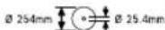
3601M2700.
3601M2703.
3601M2706.
3601M2707.
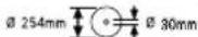
Apa dNckciHIN enIeMdepHe Ha3ap aydApbHbI3.CaHbIay dNaMeTpI acnan
wnHdine6oc KybcBc3caKeC Kenyi Tnic.ErepKaIFaTbIPbIwTeiKTI naDnanyKepek6oNca,
Kanfactbipfbl TeTik enWemepi apa
nckicihi KaIbHdbfbHa XHe
caHbIaynapdbHdAmeTpIHe XHe
acnan HnHdienihDnAmeTpIe
caNKeC bONFaHbHa Ke3 KeTki3iH3.Apa DnCKICIMeH 6ipre KeTki3iInrE
JalfactbIpbIeTefKtePdI naaanaHbHb3.
ApaDnckiciHHaMeTpbiBenrideri DepekeCaiKec Kenyi Tnic.
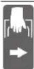
TacbImaay yin HneKtp KypanbH IN TcOcb6enrIneHRe HepnepineH (yCTay OohkTabbl) YCTaHb3.
BenrinepeHonapdbinMaibhacbi

3NeKtp KypaBih EwKaWah
XbJXbMaJIb TyTKaHbIH Ca6bIHcYCTan
TacbMaJIdAmHaBbI.

Tik enic 6bpyiWtapbiHda con Hemece OH kai TipeiyiI IaHaKc y3apTKblBih XblJXblTbHbI3 Hemece TOIbIFbIMeH anbln TaTaHbI3.

KbickbIITyTkaaBbIK: TIK enic 6ypblIHTapbH petteyre 6onabbl.
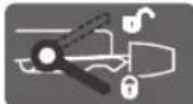
Kbickbl Tytka Xabik: KblnnbMaIbl TyKaHbH petteTeh TIK eHic 6ybpbl caTanabl.
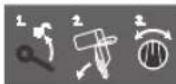
Tik enic 6ypbuibn peTey yuih 6eek KaamapdbkepceTei.
1.KbikBkiIITyTKaHbI6ocatY
2.XbIINXbIMaJIb TYTKaHbI a3FaHTaI CONFa Kaibpy
3. KaKeTITIKeHc6bpyblbHHaMafBbHb6ypayTeiriHpeTey
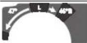
Tik enic 6ypbblbHbH aMnafbH 6ypay Teririhpe petey:

Apa nckiciH conFa kapa enici (45^ 0^)

ApaDnckiciH OHfKaapa eHici (0^ 45^)
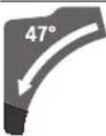
XbIINbIMaJIb TYTKaHbIH TOJIbIK KaHbipy dana30Hb(-47°...+47°)
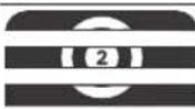
Ke3 KeTReH TIK eHic 6ypbuBHH peTey yuiH, apanay yCTeni 6oc typyb Hemece 6ypbuTb6yfattay acna6b6yfattanyb kepek:
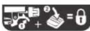
-ⅢHlTePeKTI TaPbIbHbI ①XaHe dAn con Me3eTte aIbIHbI bYpbIITbI 6yFaTTay acnabBH TEm HtepiH3 ②.
ΘHIM KHe Kyat CnnaTamaCbl

BapnbK kayinc3dk HcckaynbkTapbH
Xhe eceptnenepe0kbHb3.TexHKaNbIK
Kayinc3dk HcyckaynbkTapbH XHe
eceptnenepeCaKaTamay TOKtbH COfybHa,
opt KHe/Hemecae aybp xapaKaTTaHynapfa
anbl Kenyi MymkiH.
PainanaHyckayIbIbIHanfbi6nirihcpeTepiHeckepiH3.
Taraibihany6oibihwaKoJahy
3Jektp Kpaan Ko3raimaiTbH TipeKe 6oIaJxHe
KeJeHeHIneH, aAaTbKecyDIN TY3y 6aftbImeH Xymblc
ictye apHaIFaH. OcbiaaNsa-52°Xahe+60°
apalbfbHdAfb KJIeHeH eHic 6ypbItapbH xHe 47° (con
kak) XaHe 47° (OHXaK) apalbfbHdaFbTik eHic 6ypbItapb
Mymkin bOlabl.
3JNEKTP KypaBbHc H KyaTb KaTb XHe KymcaK aFaWtbl XHe aFaW-KoHkaBb PNTa MeH aFaW-TaWbIKTb PNTaNapFa apHaHFaH.
Tnicti apa dnckinepi nai daanahf ane anomnnn npofnnbepi meh nactkti apanayfa 60ana.
BeHHeneHren Kypamdbi 6nweKTeP
Kepcetireh Kypamdaactap HmipneHreh CypeTepi bap 6ettter3eKtp KypaBbHbCnattMaCbHa ca.
(1)
(2) KbIJIbIMaJIb MExaHn3MHINKbICbllNHTiperi
(3) TyTka
(4) AxbipatKbIITb icke KocbiydaH KopraTbH Kybn
(5) Kopfahbiw KaTtAma
(6) MaTHNKTIK KOPFaHbIi KaNTaMa
(7) Xblnkbimbl Tipeiyi nnaHa
(8) Tipeiyu nnaHaKa
(9) luineK
(10) Bypbitb6yfarayacna6bl
(11) Ke3 KeIreH enic 6ypbIbH 6eKiTkiW TeiK (KeIeHeH)
(12) Enic 6bybH andbH ana peTey nHTiperi (KeIeHeH)
(13) Ke3 KeIreH eHic 6ypbblbHa apHanfAH Kbickbl Wytka (Tik)
(14) CtaHapTbIeHic 6ypbIbHa apHaIraH OyBkTap (KeIeHeH)
(15) MoTAtJxDyK caHbInaynap
(16) ¥3apTKblIeHeC
(17)
(18) ¥3apTKbIw DeHectH KbcKbIw nHTiperi
(19) BypaHdaJIb KblckblI
(20) CbipraHaKaJeHreNeK
(21) OHKaKehic 6ybiHbHbIHdHaNa30HbHa (0°-47°) apHaIFaH 6ybiH HnKaTOpb (Tik)
(22) KoHka 6aftbTTaybIbIb
(23) XbInXbIMaNbITyTKa
(24) Tepehik wekteriwiin danyde 6paHaacb
(25) Tepehik wekteriui
(26) TaBImaayFa aPhaHaF 6eKITKi
(27) Enic 6ypbblbHbnkana cb (tik)
(28) CoJxakEHC6ypbHbHbHdHaNa30HbHa (47^ - 0^) apHaHanFaH 6ypbl HnKaTopb (Tik)
(29) 22,5° enic 6ypbibbHa apHaIFaH peTteriW TyTKa (Tik)
(30) AINbI KbiPiB DeH6eK KInT (6 MM/4 MM)
(31) EHC6ypbblbHbH WkanaCb (KoJdeHeH)
(32) Ehic 6ypbibihbHnDnana3oHbH peTeyre apHaIraH 6ypay Tetiri (Tik)
(33) Apanay ycteni
(34) ApaДиСкісi
(35) Copy aanrepi
(36) KOhkaHbI wblrapyfya apHaHFaH KeTKe Ky6bp
(37) MaTTHKITK KOPFaHbIi KaTtAma TaPty MExaHN3MHiH 6yTaTTay 6ypaHdacbl
(38) MaHTHnKTIK KOPFaHbII KaNTaMaHbIH TapTy MExaHn3MpeI
(39) AnbHb6eKITkiu 6paHa (KaTama naneB/maTHnKTik KOpFaHbiu KaTama)
(40) ApTkbl 6ekitkiw 6ypaHda (KanTama naHeBb/MaTHNKtIK KOpFaHbiu KanTama)
(41) KanTama nHaHeNb
(42) 1nnndb6ekitki
(43) Apa dncicin 6ekityre aphanraH anTbI Kbpnl bEh6ek 6ypaHa
(44) KbickiIaHeu
(45) 1uKi KbICbIuΦnaHeU
(46) XbIbXbIMaIbTIpeyiU nnHaKaHbI 6yFaTay 6ypaHdaCbl
(47) BaocenTki
(48) BaeHdTeyDin peTteriW 6paHdaIapbl
(49) BypaHdaIbI KblckblI cHbInaynpbl
(50) BypaHdaIbIe3ek
(51) EHC 6ypbuBHa apHAnFaH 6ypbuHnDnKaTOpb (KoJneHeH)
(52) AkkpaTkbil
(53) Iwnek 6ypaandaapanbI
(54)/ 0^ heri3ri npaMetpiH peTterii 6paHaIapbI
(55)/ (Tik eHic 6ypbblb)
(56)
(57) 45° heri ri napametpiin peTteriW bpaHacbl (con xak tiK eHc bypbwi)
(58) 45° heri3ri napametpiHH peTteriH 6ypaHdacb (OH) kTK eHc 6yblb)
(59) Enic 6pybuiu wkaanacbHbH peTteriW 6ypaHdaIapb (KeJeHeH)
(60) BypbH HnHnKaTOpbHbH 6paHaDacb (KoNdeHe)
(61) Ke3 KeTReH eHic 6pybIbHa apHaFaH KbICbIu TytKaHbH KbCy KyuH peTteriH 6paHa (tik)
(62) Ka6b6cakTacna
286|Ka3aKa
TexHnKanbIK mAnimetTep
| Паленьдik apa GCM 10 GDJ GCM 10 GDJ | ||
| Еним Немірі | 3601 M27 04. 3601 M27 0L. 3601 M27 08. 3601 M27 0B. 3601 M27 0K. | |
| Номиналы Тулынылалын КуатВТ 2000 2000 | ||
| Бос куріс Күйн'deri ai hyоу килігі мін | -1 | 5000 5000 |
| Icke кosity Тог'tьн'shшек'teyлени ● | ||
| Салмâгы EPTA-Procedure 01:2014 Кужатын саï | кг 31,6 31,6 | |
| Корганы с蓖сы | ☐/II /II ☐ | |
| Жарам'dы.apа дискиерін(eшем'depi | ||
| Ара диссісін.dиаметri MM 254 254 | ||
| Ораз дись.Kал'tьн'dыfbl MM 1,7-2,6 1,7-2,6 | ||
| Мakс. кесік eни MM 3,2 3,2 | ||
| Салыay диаметri MM 25,4 | 30 | |
Mniimetep [U] 230 B kecimdi kepheyre ahaHanfah. Baacka kephey xhe ende kaibnHaH raanapy mniimetepi e3reptyi myMKH.
PyKcat etinre h daibHama enwemepi (MaKcHmAldb/MIHNHmAldb): (kapahb3, PyKcat etinre h daibHama enwemepi", Bet 291)
Uybibn 6oBbHwa aKnapat
EN62841-3-96oHbHwaecenTeTReH WybIN 3MHCCHcBHBKepcetkiuTepi.
3nEeKtp KpyanbHbH aMnNHTya 60bHwa ecentenre H sybn DeHRei aETTE KeNeciJe 60aIbI bIbICbIK KbICbIM DeHRei 93 d5(A); db6bcTbIK Kyat DeHRei 106 d5(A).K daNCiaDiR = 3 d5.
KynaKopFaHbIcbiH TaFbHbI3!
Ocb ecpeTnepe 6epinre H sybl nbirapy mHi HopMaIbIK enwey aici 6oBihwa ecentren reh 6oBn3neKtp Kypanadpbl bi-6ipimeh canbiCTbipy ywiH naDanaHbinyi MyMKIN. On sybl nbirapy MHH WAMANAN eIwey yiwH de KaapamdbI.
BepinreH wybln wbfapy mHI 3neKtp KypanblHbH Herizri
KymbCTapbl ywiH 6epinre. Erep 3neKtp Kypan backa
KymbCTap ywiH 6acka anMaIbI-camMaIbI acnTAP MeHeH
Hemece ketimci3 KyTuMeH naIdaHaBInca Wybl WbFapy
Mehdepi e3repeDi. Byn Kymbc 6abbcihdafl Wybl WbFapy
MHiH apTbIpaBl.
Wbyin wbfapy mOHn HAcTb ecntey yuiH Kypan oWipinre HKeHe KocBInFaH 6oBn NaJaDaHaBImaFah yaKbITapDbI da eckepy KaKet. ByJxMbic YaKbITbHdaFbI Wbyin wbfapy mOHIN TeMeHNTeJI.
MOnTaXkDay
3NeKtp KypanbHbH Ke3eDcok,icke KocbinybHa Kon 6epMeH3.OpHaty Ke3iHe Je3eNeKtp KypaBbHdaFbI 6apbIK JyMbictapda Keni aibipb ToKka KocbInMaybKepeK.
Ketki3y konemi
On yuiH naiDanaHy hcyKaynbIbIbHI bAcBHaIaBfXHHAK KypamblIH CnAaTamaCbH KapaH3.
3nEeKTP KpyanbH anfawkbl pet icke KocyaH aIbnTMeHne Ka3bInFaH 69iikTepeH xHnKaTa 6apbIbHbTeKcepH3:
- ApaДиСКICI opHaTbIfAn NaHelenBik apa (34)
- Bekiry teriri (11)
Kbicy TYTKblbl (13)6ekitkiu KnaKeH
¥3apTkbI W TyTkbl (16) MeH KbICKbl W TyTkblw (18) 6ekTIkw KHaKnne
-11aHka6bl(1) - Antbl Kblpbl DeHbEeK KInT (30)
BypaHdaIbIKbcKbII (19)
Hcy:3neKtp KypaBih 3akbImaHynap 6apblfbiHa Tekepii3.
3nKtp KpabH naDanaHydAn anBbH KopraBw acanTap Hemece a3aKbIMdaFANf H6NIkTepDi 66den MHCi3 Xhe Dpybc icTeyIH TkecepH3. XblkbimAbI b6eKeTp Kepepric3 icTeyIH XHe KbcImaybH Hemece 6NIkTep 3aKbIMdaMAfaHBH TEKcepH3. BapNik 6NIkTep dypbc opHaTbIFAH XHe KepepriciX MybIC icTeydi KaMTamacbi3 etTIN naDanaH yapTAPbHa cA8 OByI KepeK. 3aKbIMdaFANf KopraBw acanTap MeH 6NIkTep ekinetti We6epxahana XHeNey Hemece amMactbype KepeK.
XHHaKaTah TbIc KepeKti acnantap:
KpeT Tepi3di bypayb
-ДинhamOMetpni kint(entmei:8MM)
-ⅡeReneKti,aibpTap3iHemeCdeH6ek KINT (enwemepi:10MMxane17MM)
Beniktepih ophaty
-ⅢKaTb6eJIKTePia6aIaan opamaHb3dAn aIbIN KObIHb3.
-5yTIN opama MaTePnaIbIH 3JIeKtp acnAn nen JxHaKaTaBj Ka6dbkTapdah anbln KOHbH3.
Bekiry teririn opnaty (acypetin kapaib3)
-BeKiyTeTirin(11)Tnicti Tecikke TTKbIbHbH(12) yctInde6ypan6eKtIH3.
6ekit6acbiH(11)apanaydaan andbinepaibim 6ekem6ekitik3.ηItnce apa dnckici daibHaMaDa KHCABIOyMVKIH.
Ke3 Kenre h enic 6ypbbl yin HkbickbI tyTka (BepTKanbbl) opHaTBHbI (a cypetih KapaHbI3)
KbCy TyTkAcBn (13) opHaty ywiH xHHaKTaFbI 6eKITKiW xHHaKTbI (DeHBeK KIn, CombH, 2 apanbIkwHep) naJdaHaHbHb3.
-50nikTeepi KepcetinreH petinikte (ynkeh apanbik weH6ep, kcy tyKacbl, kiwi apanbik weH6ep, combi) 3neKTP KypaBihdaftToNb6ypaHdaIb 6oTTapFa canblHbl3.
-CombiHbI TaTpya JaaKcbipak Kyu eTKi3y yuiH XHHaKaTafbl anTb KbpIbn DeH6ek KInTI (30) DeH6ek KInTIH TecikTePihe canhbl3.
- CombIHdb KaTbI TaPbIN KoBihbl3.
¥3apTkbiu TyTKaHbI opHaTy (b cypetih KapaHb13)
¥3apKbIiTytKaHbI (16) opHaty yuH iHN HnHaKaTbfI 6ekitKiU KnHaKbI (2 KbICbIi TytKbiU (18), 2 KaTnapblb 6ypaHdAmA, 2 domaata 6ypaHdAmA).
-3apTbIuTyKaHbI(16)TipenreHue caItecikTepreapanay yTeiHne(33)KblNkbltBhl3.
-OManatna 6pyaHdamaIapdbI KOIMeH TOnbIFbIMeH caI TecikTepe caIbIHbI3.
-OMaIaMa 6paHaMa 6acbHa KblcKblu TYKblU Tbl (18) OPHAblB3.
-KbickbiT TyTkblTbI (18) KaTnapbl 6ypaHdaMaMeH 6ekTIH3.
Kbickbl TtTkblTbH Kbcy KyuH (18) KaTnapbl 6ypaHaMaHb JnHaKaTaftbl AnTb Kbpbl Deh6ek KintneH (30) TaTbH KOblHbI3.
KaTbI Hemece KEmDi opHaTy
TypakblnainanahyblkamtaMa3b3etywih3neKtp Kypablnnainanahydaandbin teric6ekemxymbic aHaBHaMbCaBbBepctak) opHatyKepeK.K.
Kymblc6etihemontaxkday(c1cypertinkapaib3)
-3neKtp KypalbH JkapamdbI 6ypaHdaI bKOcbJbIMMeH Jxmbic 6eTHe 6ekitih. On ywiin cahbnaynap (15) naJaanaHaBnabbl.
Hemece
-3neKtp KypaIbHbH aRkTapbH cTaHApTTb6ypaHaJIbKbICbIHTaMpMeH Kymbc aHMaftbHa 6eKiTiH3.
Bosch xymbic yctenihe opnaty (c2 cypetih kapahti3)
(GTA 2500 W, GTA 3700, GTA 3800)
Bosch ycbihfag GTA xymbcic yctenepi 3neKtp KypanapbH 6nktiri peTteniH aKtapbl apkbl Ke3 KeTRe H 6eKeTei. Xymbc ic ycteninderi daBihdama TipeyiHTepi y3bH daBihdama npbl Tipeye arpanfaH.
Kymbc yCTeni KINHafblHaFbI 6apnbik eckepTynepeMH HcaynbIKTapblOKbHbI3.EcKeptnenepeMH HcayblKTapblCaKaTamay TokTBH CORYbHa,ep XaHe/Hemece aybp kapaKaTTahynapra anBIn KenyIMMKIH.
3NeKtp KypanbH opHaTydaH anDbH KyMbic YCTenIH Dpybc KpybHbI3. 6y3biny KayinH 60ndbIpMay yuiH MHCi3 Kpy MaHb3dbl 60bnH Kanabbl.
-3neKtp KpaIbIH TacbImaIay KyHHe JxMbIC yTeJIHe OPHAbIbI3.
UaHdbj kOHe KOHKanapDbicopy
KopfaBH6oay,Keibip aafu copTapb,MHepaIap JHe MeTALIAP 6ap Keibip MATEPAIAPdbIH. WAbi DeHCaybIKKa 3HHdbI bonybIMyMKH. LHaFA TIO JHe WAnDb JxTy naDalaHuybida HEmce KaHbINaFbI aamdapa annepeRnblk peakunnapbJxHe/Hemce TBHbIC KONdApBHbH aypyapbIH TybipybIMyMKH. Keibip wahTypnepi, acipece emeH xHe waMaat aafuBHbIH WAhbl, acipece, aafuTbE hDey KaNbIKTapbIme (xpomat, aafuTbI KOPfay 3aTb) bipre KaHcpePoreHep 60bn ecenTenei. Ac6ecTK MATEpHaI TE Kaha MaMaHAp apKbbl eHDenyi MyMKH.
MymkiHwiniirHwe Ocbi MaTePnA yuHcAeyKeK cKeTIN WaHCOPFbIHTbI NaDaHaHbHb3.
-朱mbicOpHbHbHjKaKcbJKeJeTeiYHe Ke3KeTki3iH3.
-P2 cy3ri cbiHbIbIHdaFblra3kaFapbl naHaAnaHycblbIaNbl.
HneneTIN MATEpnaIap yin eniH3e KOndaHbIaTHyFapbIMapDbI naHaNaHbIHbI3.
KanaFaHaHb3. Hohai tyTaHybIMykH.
JHa/koKa copy 1aH, KOHa HeMeCe daBihDama CbHbIKTapbl apKbIbI bTfBf3aHybl MYMKIH.
-3neKtp KypaBnH eipin xeni aBipbH po3eTKadaH TaPTbIN KOJIbHI3.
-Apanay dncici TOnbIK ToKtaFaHbIwa KyTe TypbHbI3.
-TbIfb3danyce6e6ihaNbHdaonohjXoJbHbI3.
Θεινίκ copy (d cypetɪn kapaɪbɪz)
KoHaHbYcTananyyuiHxHaKaTaBlaWHaXHaFbIaKanTb1 (1)naDanaHbHb3.
-ⅡaHJINHaBfBnKanTb(1),copy aanTepinH(35)ictiri ⅢaHJINHaBfBnKanTbHcAHybIaybHa KipetInDee etin,copy aanTepine ehrizin,bypaHbIa.
JHnHaBki Kan apaay KeiHde KblKbImanbl KypblFb6nIKtepihe Tmeyi Tnic.
WahJHHaHbI KAnTbI dep Ke3iHde 6ocatbHbI3.
WanXHHaBbI KAnTbI eP naDanaHraHHaKeIH TEKcepin Ta3anaHb13.
288|Ka3aKa
OptKayinih andbih any yiwih anHomHHn di apanay KeiHde wah XHHaBfW KanTbI anbIn TaTaHbI3.
Cbiptkbi copfbiu
Wah copy yuih copy aanantepine (35) wahcopfbiw wahriciH (dAmetpi MM) de kAnfayfa bonaabi.
-ⅢaHc0pFbIwIaHaRicin copy aadantepihe (35) XaHaB13. ⅢaHc0pFbIwEhDenetIH MaTePnAflra caKeC 6onyblKaXeT. DeHCayNbIKKa 3NHN, O6bIP Tyfbl3aTbH HeMece KpyFAk ⅢaHap yWIn apHaBb IaHc0pFbIwTb NaDaIaNbHb13.
Copfbw ananterepi ta3anay
OHTaMbI copybl KaMTaMaCb3 ety yuH copy aanTepiH (35) xynenl type TaanaI npy KepeK.
-Copfbiw aanTepni (35) 6ypan KOHka WbifatbH JepdeH (36) WbifapbHb3.
JaBbHdAmaHbIH ChbIKTapbI MeH KOHKaIapbIH aIbIN KObHb3.
-Copfbw ananeppi 6ypan KOHka wibfathj Kepre KOFAa Wbifatih Kepin yctay caknacbiHbH XOFapbcihda TipenreHwe 6ypan 6acbiH3.
Apa dinckicih anmactbipy (e1-e4 cypetrepin kapaHbI3)
BapnbKxymbIcTapdaH andbH 3neKtp KypaibHbH Jkeninik aibpbiH po3etKaadH bIfapbHb13.
Apanay Dnckicin Ophaty Ke3iHc KOpFaBliu KonFran KniH3. Apanay DnckiciHe TtReHde JkapaKar any Kayni 6ap.
MaKcHMaIbI pyKcAt etInreH kblIaMdbIfb3neKtp KypaIbHbI3dbH 6oc aHany MOMeHTHe XofapbI 60fApaanay dNckinePi naiDanaHbHbI3.
TeKocbnaIaIaNAnHyHcyKaYbIbIbHa 6epinreHepeKTepe CenXeHEN847-16oBbHwaTeKcepiReH 6oBnTnici peTteBcInireHReApanayDnckinePiNaIaIaNbHb3.
TeKocbIeNkTp KypaIbIbHbIeHdIpuyiCiYcblHaH XHe ci3 eHneTIH MaepnAnFa caiapanay dncKinepiH naIanaHbIbI. Byapanayda apa ticTePiH KbIbIn KetyiHe kon bepmeNi.
Apanay duckicih ueuy
-3neKtp KypaPbIH KymbIC KyiH e KeTipiHj3.
-6yfattay 6ypaHacbH (37) aIbI bKipnb Deh6ek KInTne H (6 MM) (30) TaTy MExaHn3Mi (38) epKiH acblbn TypaTBnDaen 6ocatbHb3.
-BeKITki6bpaHaDaHb3(39)(wam.2aHnAbm)anTbI KbpIbDen6kKiTTneH (4MM) (30) 6ocatbHb3. BypaHaHbToBik6papanbifapMaHb3.
-6ekitki 6ypaHaHaHbI (40) (wam. 6 aHaHaBIM) aNTbIKbpNl DeH6K KInTneH (4 MM) (30) 6ocatbHbI3. BypaHaHbI Tobnk 6pan WbIFapMaHbI3.
-KanTama naHenbIi (41) 6ekitkiu 6ypaHaadn (40) anFa JhHe TEMeH Kapai TapBIn anBih3.
MaTHNKIK KOPFaHbI W KaTAmaHbI (6) apTKa KaHbIpBn, MaTHNKIK KOPFaHbI W KaTAmaHbIOcb KyHe yCtHaB3.
-TapryMexAHmM(38)caHbIaybH6eKITkiu 6paHaFa(40)kapatbninihj.
OcbIaMaaMaTHTHKTIK KOPFaHbII KaNTaMa aUbIK KyIe CaKTanabI.
-AntbKbpNbDn6ek6paHdaHb4(43)antbKbpNbI dH6ek KINTneH (6 MM) (30) 6ypan, dAn con Me3eTte WnHdJI b6kITKiW (42) TipenreHe wacBhl3.
-ⅢHnHdNb6ekitkiHIN (42)6acbin typbin,antbKbIPnbl DnH6ek 6ypaHaHbI (43) caFt TiniH6aftbIMEH 6ypan 1bIFapbHb3 (con JAK Hpek Oma!).
-KbickbiuФnaHeuT(44)aIbInTaTaHbI3.
ApaDnckiciH(34)WBifapbHbI3.
Apanay duckici n ophary
Ophyda ticep kecy 6afbltbi (apanay dncicinde Kpcetki 6afbltb) Koprafbu KaTama Kpcetki 6afblbImeH caiKec 6onybHa Ke3 XETk3iH3i
KaKet 60nca, opHaTbInaTbH 6apNbIK 6eNikTePgi opHaTnac 6ypbIH Ta3anan WbIfbHbI3.
-Jaapa daNckicin iwiKki Kbiickbl W pnaHeKe (45) opHaTbHb3.
- KbickbIΦaHeuTl (44) Xhe aNTbI KbipIbIeH6ek 6ypaHaHaBt (43) opHaTbHbI. UHHDeNb 6ekITKiH (42) TipeReHwe 6acBn, anTbKbpIbIeH6ek 6ypaHaHa bI caFATtiHIN6afblhAkapcbI6ypan TaPTbHbI3.
Tapmy MexaHm3H (38)6ekitkiu 6ypaHaDaah (40) 6ocatbIn, MaTHNtIK KOPFaHbIi KaNTaMaHbI (6)TeMeH Kapai KaTadaH anapbHbI3.
-KaTama naHEnbdi (41)6ekitkiw 6ypaHaDaHbH (40) actbHa KaTadaH KblkbItbn KOblb3.
-(40)KHe(39)6ekitkiu6ypaHdaIapbH KaTadaH MbIKTaT TaTbHb3.
-Tapry MexaHmIH (38) 6actanKbl KyiHe XblkbItbIn, 6yfaTay 6paHacbln (37) anbl Kblpbl DeHbEe Kintneh (6 MM) (30) KaTadaH Tapbln KOIBHbI3.
Paindanahy
BapnbKxmbCTapdaH andbH 3neKtp KypaibHbH Xeninik aibpbiH po3eKaadH bifapbHbI3.
TacbMaIay Ke3iHderi KopFaHbIC (A cypetin KapaHbI3)
TacbImaay Ke3iHderi KopFaHbc (26) 3neKtp Kypanbln aptynj MyMbC opbHapbHa TacbMaay Ke3iHde KonaNbl naaanahyfa KeMeKTecedi.
3NeKtp KypaBbH KopFaybIbHaH 6ocaty (XyMbIC Kyi)
- XblnkbimablyTytkbiWb1 (23)(3) a3TeMeH 6acbl TacbImaIay KopaFaybiWBiBn (26) 6ocatbHbI3.
-TacbImaayKopFaftlbHb(26)TolbIKcbIPTKaTaPbHb3.
JbIbXbIMaJIbTyKaHbI (23)XaJXoRapBaIgSaBfTaHaIa.
3NeKtp KypanbIH KopraybIbIH opHaty (TacbIManday Kyi)
KbIINkbIMaIbTyTKaHbI (23)TOnbIFbIMeH apTKa KblNkbITbn,OCb Kynde6ekitih3.
XbInXbIMaIbTyTkaHbTaCbImaNdayKe3iHderiKopaHbC (26)TObnkTainike KipreHeUe TEmEH XblnXblHb3.
KocbIMHa Hcyckaynap:TacbMaNday
XbinnkbimnbtyTkahb6yfTay
KbIbMbImbl TyKaHbH (23) KbIbKbIy MexaHm3Mn KbcIKbIb TyTkbl (2) KOMerimeh 6yFaTTayfa 6oNaIb. OHda KblNkMbImbl TyTkada eki Kyi 6oNaIb:
JbIJIbIMaJIb TYKahBI TOJIbIFbIMeH apKaFa KblNkbITbINFAH (koFapbiDaH kecy yuii)
JXbIJIbIMAbI TyTKaHbI ToJIbIFbIMeH anFa TapTbINFaH (TyTac TaCbIMaNay Kyi yuIH)
KbInKbIma TytKbIITbI WbIFapy (B1 cypetin KapaHb3)
XbIMaJIbTyKaHbH (23) 6yFaTaybH aWKaHH COH TOBIK XbINbITY MExaHN3MHN naDanaHyfa 6oJabl.
-KbickblTytKblblTb(2)TeMeHre TipeHre He6acblhla3.
Kbickbl TTKblTbH Kbickbl CbHaCbl KblnBmAbbl TYKaHbH TeMeHri Eki tonCaBH 6ocatabI.
Kbinnbima Tytkahbi 6ekity (B2 cypetih kapahti3)
XblnXbImaBl TyTKa TOIbIFbIMeH apKaFa XblNkBtBlnFaH:
- XblnkbmabI TyKaHbI (23) tipenreHwe apkara XblnkbTbIHbI3.
- Jxbljkbimably TTKaHbH eki XoFapfbl tonca bI eHdi teric Typbn Jaa6bIK 60bn typ.
-KbickblTytkbilTb(2)KOFapbifaKbickblciba HxblXbImaIbTyKaHbHekTIeMeHRI TOnCaIapbHbH apacbiHaOpHaTbIfaHa TaPbHb3.
-ApKaFa XbIINKbITbnfA H XbINKbIMaJIb TyTKa (23)ocbln 6yFaTTanaJIb.
KbIMKbIMaIbTyTKaTOnbIfbImeAJFaTapTbIFHa:
- XblnXbImaBlyTytKaHbI (23) TipenreHwe anFa XblnXbITbHbI3.
-XbIbXbIbTY MExaHn3Mi eHdi TOnbIfbIme HbIFapbIFaH.
-KbICBblTtKbIITb1(2)KOFapbIaKbICBblCbHaXbIJIbMaIbTIyTKaHbHI EKI TeMeHRI TOnCaIapbIHbI,apacBHdaOpHaTbINFaHuaTapTBHb3.
- TOnbIbIMeH anFa XbINXbITbINFaH XbINXbIMaJIb TYTKa (23) 0cbInai Byfattanabl.
Kymbicicteyre daaibihday
Apanay yctenin y3apTy (C cypetin kapaHb3)
¥3bHn DaBnDamaJap 6oc 6acBnDa 6acBnTipenyi KepeK.
Apanay ycteninH daBHdama tipeiyiU zapKbiu tyTKaHbH (16) Kemerimc conFa XHe OHFA YIKeYrTe 60nabI.
-KbicyTyTKbluBH(18)apKaFaKaHbIpbHbI3.
-¥3apTKbIITyTKaHbI (16) KepeKTI y3bIbIKKaJeHH CbIPTKaTApTBHbI3 (MaKcHmAnbl 204MM).
-3apTkiTuTKaHb6ekityyuihKbickbiuTyKbHtbl(18) Kaeta cbptka 6ekitih3.
Tipeiyi nnaHkAbhixkbnXbity (D-
E cypeTepin kapaHb3
KeIeHeH KeAe/Hemec 6ybpItapbH apanay Ke3iHne Kecy baftbHa 6aIIaHbICTbCOn Hemece OH KaKxbIMaJI bTIpeiyu nHaHKaHb7 (7) CbPTKa TapTy Hemece TOnblkTaNbln Tactay KepeK.
tic enic 6ypbmbkndeneh enic
| 6урshiы | ||
| 0°-47°(con.jaк) | ≤ 44°(он/con.jaк) | -Бугтay 6уранданьн (46) 6ocatbih3. -Con.jaк,Жылжымалы TIpeyiш палнkaны (7)Толык сыrtka Тарынbi3. |
| 0°-47°(con.jaк) | ≥ 45°(он/con.jaк) | -Бугтay 6уранданьн (46) 6ocatbih3. -Con.jaк,Жылжыmалы TIpeyiш палнkaны (7)Толык сыrtka Тарынbi3. -Жылжымалы TIpeyiш палнkaны XOFapbi кETepiIN КОьнbi3. -Бугтay 6уранданьн (46) anbIn TactaHbi3. |
| 0°-47°(он.jaк) | ≤ 44°(он/con.jaк) | -Бугтay 6уранданьн (46) 6ocatbih3. -Он.jaк,Жылжыmалы TIpeyiш палнkaны (7)Толык сыrtka Тарынbi3. |
| 0°-47°(он.jaк) | ≥ 45°(он/con.jaк) | -Жылжыmалы TIpeyiш палнkaны XOFapbi кETepiIN КОьнbi3. |
KbIINkbIMaIbI TYTKaHbIH 6oCeHdETKiUH peTtey (FCypTeIH KapaHbI3)
XbIMbIMaJIbTYKaHbIN (23) XbIMbIb TY MexaHn3Mi 3ayblTa anlbH ana petteIenre 60bn, 3neKtp KypabJI bKeTkiinre Ke3Ine 6aceHdTeINmere H Kynde 60anaJI.
KbInKbIy MexaHn3mHIN 6aeHneTiny IN Keke pette 6aceHnetkiTe (47) peTeyre 6oana:
KaTbI-6aKbIaNHaH KMyBMcapeKeTTepi;
Kymcak-KbIaM apaaypekeTepi.
-Eki peTteriH 6paHaDaHbI (48) aNTbl Kbpnl dHbek KInTneH (4MM) (30) xymcaK 6aceHdety wH 6ocatbHbI3
- Hemece
-ekiperteri6bpaHdaHb48KaTb6aceHdetyuH KaTbI TapTbIHb3.
JaBHHaMaHbI 6ekiry (G cypetIH kapaHb3)
ONTMaJIbI JxMbIC Kayinci3irH KaMTaMaCb3 ety yuHJ daBnHaMaHbI apdaiBIM bekem KbcIcy KepeK.
KaTbI KbcyFa eTe KiWi 60nFaH daBbHdAmanapdbEHNMeH3.
-Даиьндаманы TIpeyii nlaHkafa (8) 6acbHb3.
-ⅢHnHaKaTbFb6pyaHdAblkbckbltB(19)OafapHaIraH TecikTepe(49)canhbl3.
-ДаиьИндаманы 6урандалы eзкTi(50)6урпknбсIHbI3.
290|Ka3aKa
KoJdeneHxHeTikEhic6ypbuBn peTey
IaN KecikTePdi KaTAmacb3 ety yuiH KapKbIHDbI TypDe naDanaHaFHaHn KeiH 3neKtp KypaBihH Heri3r peTeyepin Tekcepin, kaxetihwe petrey kepek bona.
On yuHIN TaXipnBe MeH Tnicti apHaHb acnantap KaKet 60ana.
Bosch cepbntik optabif6yI Kymbictbi Xblam api ceHIMI Tpye eKtkei.
Pterriu terikti (11) apanaydan 6pybH npaBIM HbIK TaPTbHbI3. OHTnece apa nnckici daBnHaMaJa KNCAHObl MYMKIH.
Topn3oHTanDbI eHic 6ypbIbIh petTey
TOpH3OHTaIbIbI cTaHdApTTbI eHic 6ypbluH petrey (H CypTeIH KapaHbI3)
Kni naianaanbinahtin eic 6ypbiutapbin kbniDam opi dme-pan petrey yuih apanay ycteniHne oyBkTap (14) 6ap:
conda OHDA
0^
45^;31,6^;22,5^;15^15^;22,5^;31,6^;45^;60^
-BeKiy 6acb1 (11) TaTbIHFaH 6OcA OHb 6ocTaHbI3.
-TyTKbIUtBt (12) TaTbI apanay yCTenIH (33) KepeKTI OBykKa DeHIN CONFA HEMeO hFa bHaB13.
-TyTKbIHTbI KI6epH3. TyTKblcEImi peTte OHBIKa Kipy I KepeK.
-BeKity 6acbH (11) KaTt TaTbHbI3.
Ke3 KeIeH KJIeHeH eHc 6ypbIbH petTey (I cypTeH KapaHb13)
KoIeHeH eHic 6pybIbH 52° (con JaK) JxHe 60° (OJxA) apalbfibHa peTeyre 6oana.
-BeKtiKi6actNeK(11)TapbINFaH 6oJca,Ohbl 6ocatbIHb3.
- Hntipekti (12) TaTbIn, dAn cOn Me3eTe aNdbHfbl 6ypbWtbl 6yfaTay acna6bH (10) TeMeH nTePiH3. Byn pette HntipeK (12) 6yfaTaNbIn, apanay yctenIH KblXbIty MymKIn 6oNabl.
-Apanay yctenin (33) 6ypbuHnHkatoptb51 kaxetti eHic 6ypbuHIn KepcTeKeHwe 6ekity bactneriHeh conFa Hemece OHfa 6paHbi3.
-Bekeiy bactnerH (11) KaTtanaH TaPbHbI3.
IHTipeKTI (12) KaTadaH 6ocaty yuH (KeJdeHe cTaHapTTbE Hc6ypbTuTapBn peTey uH) iHTipeKTI KOFapbKaapan TapTbHb3.
BpybIbI 6yFaTay acna6bl (10) 6actankbkyiHe opaBIn, nHTipeK (12) ObykTapbiHa (14) KaTadaH Tycyi MymKiH.
BepnkaIbIbeIeIc6ypbiuHpeTrey
KoIeHeH KncaHTy 6pybIbH 47° (conKaTbIK) MeH 47° (oh KaTbIK) apaIbIbIHda peTteY MyMKH.
Kni KOndaHaTbH enic 6ypblbH Xblnam XHe hAaTbI peTey yuH 0°, 22,5°, 45° XHe 47° 6ypblTaBbY uH tipeyiwep KOndaHbInabbl.
ConBepTKkAnbblEhC6pybIHTapbIHbIH aMafbH petrey (45^ - 0^)
L
- CoJ KaK KblNkbImaBtipeyiHnHaHKaHbI (7) TOnbIK cbIpTkA TaPbHb3.
KbickblTytKaHbl(13)6ocaTbHbI3.
JbIbIbIMaJIbTyTKaHbI (23)KoI TyTKacBHaH (3)YCTan, 6ypbl HnDnKaTOpbl (28) KaKeTTi TIK eHic 6ypblbH KepcTeKHeWie CoFa KaBlpBlH3.
JbIKbIMAbI TyKaHb (23)OcbkyiJe yCTaN, KbiKbIITyKaHb (13) KaHa6eKtiH3. KbiKbIH TyKaHbIH KbiCy KyuKe3 KeRHeTik EHC 6ypblHda XblkBImAbI TyKaHbIKyInh BeKem YCTa KepeK.
OHKaTikEHC6bHbHbHdHaana30HBH petTey (0^- 45°) (JcypetIHkapaB3)
45°R
-OHKaKbINkbIMaJIbTIpeyiUINaHKAHbI(7)TOnblK CbIPTkA TaPTbIHb3.
-KbickbiTytKaHbi(13)6ocatblhla.
- Jxbljkbimably TTKaHb1 (23) Kon TTKacbHaH (3) yctan, 0° KyyiHeH a3dAn conFa aydpbHb3 xhe 6ypay Tetirih (32) KaKETTI tIK eHic 6ypbuBbHbH dnaana3oHb KepcTeInreHwe 6ypaHb3.
JbIbIMaIbTyTkaHb(23)KoI TyTKacbHaH(3)yCTan, 6ypbIHINdkaTopb(21)KaKeTTi eHc 6pyblBn H KepcTeKHeWe OHFa KaibpblHb3.
JbIbIbIMaJIb TYKaHb (23)Ocbl KyIe yCTan, KbcKbIITyKaHb (13) KaTaN 6ekitih. KbiKbIITyKaHbIH KbcCy KUJI Ke3 KeRrEHtEHC 6ypblHda XblXbIMaJIb TYKaHbIH KYINH BekEM YCTaybl Kepek.
BepTKkanaDbblcTnndapTbIeHic6ybiu0peTHei3
BepTKaIb cTahapTb 0eHic 6ybiuH OHa KaTapeTey yuiH 6ypay TetiriH (32) con BepTKaIb bEiC 6ybiuHbH dnaa3oHbHa Tipenei.
-Жынжымалы TуТКаHы (23) OH,ЖakTaH 0° KУиHeH eTKi3in KaырblbI3.
ConBepTKanbDbeEic6ypbIHTapbIHbH aMafBH petTey (-47^ + 47^)
47°
-EkiXbIiXbIMaJIbTIpeyiiHnHaHKaHbI(7)TOnbIfbIMeH CblpTkA TaPbHb3.
KbickblTytKaHbl(13)6ocaTbHbI3.
JbIbIMabI TyKaHbI (23) KON TYKacBHaH (3) YCTan, 0 KyiHeH a3dAn conFa aydpabHb3 XaHE bypay TetirH (32) KaKETTI TIK eHic 6ypbIbHbIH dVana3OHi KepcetireHwe 6ypaHbI3.
JbIbMbIaBlyTtKaHbI (23)KoN TtKacbHaH (3)YcTaI, 6pybIH HnDnKaTopb (28)HEmece (21) KaKeTTi TK eHIC 6pybIbH KepCteKHeWc CONFa HEmece OHFA KaBbipbHbI3.
JbIbIbIMaJIbTyKaHbI (23)OcBI KYIe YCTAN, KbICBII TytKaHbI (13) KaTaN 6ekitih. KbICBII TyKaHbIH KbcIcy KyWi Ke3 KenreH TIK eHic 6ypblHda XbIbIMaJIb TyKaHbIH KyHH 6ekem yctaybi KepeK.
BepTKaNbblcTaNapTbIeHic6ypbIb22,5°peTHei3 (K cypTeIH KapaHbI3)
PeTey TymMeecin (29) cbtpKaToIbIbIme TaPbIIN 90°-Ke 6ypaHb3. CoCbH KblKbIMaBly TyKaHb1 (23) KOnTyKaJAH (3) KblKbIMaBl TyKa eCtinI tipenReHue KaBbIpHb3.
PaindaIaNyFa eHdipy
Icke Kocy (L cypetih kapaHb3)
-3neKtp KypaBihicKe Kocv yuH anbimEn Kynbintay TetiriH (4) optara XblnkbTbn, codan Kein aXkbpatkbWtB (52) 6acbin TypbHb3.
HcyKay:Kayinci3ik ce6e6ihen Kockbui/ewipriu (52) Kyblntayfa 60nmaui, on kymbcic iTey Ke3iHde bacinfaH 6onykaxket.
Θwipy
-0wipy wuiin Kockbiw/ewipriwi(52)xi6epiiz3.
Icke Kocy Torbihh WkTeynepi
Icke Kocy torbHweKteYdiH 3neKtpoHdbIKxyneci 3neKtp Kypanbl Kocy keiHderi KyaTbI weKteJdi Xane 16 A po3eTKadaH xMlbic icTeey MymkiHik bepedi.
Hcy:Eep3nKtp Kpyan Kocyaan Kein 6ipen ToIbIK aHaJIbIMap caHbIMeH aHaHanca, OHa icke Kocy TOrbIH WeKteYKepek Emc.3nKtp KpyanBbIKbIcMET Kcpcty optaIbIbHa Jxibepy Kepek.MeekxJaInap:TytbHybIfa KbIcMET Kcpcty Xane naJdaNahy KeheCTepi.
Painanany Hycaynapbi
Kannbiapanayhcykaynapbi
BekiyTeTiri(11) MeH KbCy TytKacBH (13) apanayda andbih epaibim 6eKem TapTBIN KObIHbI3. OHTnece apa Dnckici daBHdama KaCaIObl MYMKIH.
Bekitkiu Tetikti (11) Xane Kbcicbui HintipekTi apanaydaH 6ypbH apdaiBIMMbIKTanTaptbHb3. 3ntnece apa dNCKici daBHdamaKaCaobi MymKIN.
BapnbK KecikTepde andbimEn apa dnckici Tipey nnaHkacbH, Tipeiyu 6paHda Hemece 6acka acnan 6enikTepiTHmeyine K03XeTKi3H3. MyMKIN opHaTBnFAH KEMK TipeiyuTepin aIbHb3 Hemece onapblnabIKTaHb3.
Apanay dnckicih cokTbfbCydaH kHe cokkbdaH Kopfahbl3. Apanay dnckicih byipnik kbcbmHaH caKaTbbl3.
TekTnicti naDanaHy yuiH pyKcat etinreH 3aTTeKtePdi naDanaHaBHy3.
KcbskDaBbHdAmapabDHeMeH3.DaBbHdaMaepdaBIM 6afttaybIaHene HcyyuiH typa Kbipnb60nybKepeK. ¥3bH JxHe aybp DaBHdAmanap 6oc BacbHa 6acbIn tipenyi KepeK.
MaTHNKTIK KOPFaHbIi KaTAmaHbIH Dypbc JyMbIC ICTen, epKIN XblJXbYbIH KaTAMacbI3 etiH3. MaHInyTAIOTDbI TEmeH Kapai 6aftTIay Ke3iHNe, MaTHNKTIK KOPFaHbIH Kantama aUbInyBekepk. MaHInyTAIOTDbI KOFapbl KaPai 6aftTIay Ke3iHne, MaTHNKTIK KOPFaHbIH Kantama apa dNCKicIH YCTiHEh KaTa XabblBn, MaHInyTAIOTDbIH eXofapbl KyHHde 6ekITinyKepek.
OnepatopdbH KyyH (Mcypetih KapaHb3)
3neKtp Kypanbl anbHa apa dNckicimEn 6ip cb3bIKKa TypMa, epaBbIM apa dNckiciHn WeTTe TpybHb3.
OcbIaIwa daeHcI bIKTmAn Kepe cokkbIaN KOpFaIaIbI.
-Anakah,6apMaKxHe KOnJaPbHb3dblaHaHaTaBH apanay dNcKiCHeH aBtTaHb3.
- MaHnIyIaTOp aIbIbHaKoIaDapbIb3IbIa IaKaCTbIpMaHbI3.
IwneKeTpDi aNMaTbIpy (P cypetin KapaHb3)
Kb3bn iunektp (9) 3nektp kpaanbl y3ak naaanaHfHaHH COH TO3ybl MYMKIH.
Akaynbii iunneKtepdi anMaTbipbHbI3.
-3neKtp KpaJIbH KMbIC KyIHe KeNTpiJIH3.
-(53)6paHdaapbHAnTbKbpNdeH6ekKInTneH(4MM) (30)6ypanwifapbin,eckiwnekTepeiweiinj.
-KaHaohiwnekti canbHbIa.
-ImneKti (53) 6pyaHaJaIapbIeH OH XaFbHda 6ypan KOyIbH3,apaDnckici MymKIn ApeKeTIiH 6ytih XoJIbHda iIwneKke TmmeTIN 6Olybi Kepek.
-Жуmbic6ackbIHTapbH6ipNeJkaHaconiunekywnde KaTanaHb3.
PyKcat erinreH daibihdama enwemdepi
MaKcHmAnDbikDaBbIHdAmanap:
| rogenostanbdlé enic 6bybbl | tik kucayty 6bpybbl | Биiktiri x Eni [MM] |
| 0° 0° | 80 x 306 | |
| 45° 0° | 80 x 216 | |
| 0° 45° (conda) | 54 x 296 | |
| 0° 45° (ohda) | 30 x 296 | |
| 45° 45° (conda) | 54 x 208 | |
| 45° 45° (ohda) | 30 x 208 |
MHHMaIbIckaBbHdAmaIap(=6apnbKaabHbHaMaIap, onapdbKINHAKTaFbKbICKaUHeN(19)apaNOOTHCbIHHO Hemece con KaKaTa KbcCyfa 6oana):145x306 MM (Y3bHDbfExH)
Makmamdbik kecik tepehdiri (0^ / 0^) :100 MM
Apanay
TapTy apeketinciapanay (Kbipuy) (N cypertin kapaib3
- XblnKbIMaIbI TykAhB1 (23) TOnbIFbIMe apTKa XblNkbTbn,ocbl Kynde 6ekitH3. TepeHik WekeTeriWiHIN (25) TOnbIFbIMe Iwke 6acblNybiH XHe dAnDey bpaHndacbl (24) XblNkbMaIbI TykAhB1 XblNkbTkaH Ke3Je TepeHik WekeTeriWHe TIme OYbIKKa KpyIH KaMTaMaCbIs EtH3.
-Даындаиманы сишерд配电сэксьсьл.
292|Ka3aKa
-KaKeTri eHc 6ypbIbH (KeNDeHeH KHe/HemecTei) peTHe3.
3NeKtp KpyaBbH KocBbHbI3.
- KblnkbmaIbTyTkaHb(23)KoI TyTKacbImeH(3)6aRy TEmeH 6afblTaHb3.
JaHbIHdamaHbI6ipKaJbIbITbIXyPicneHaapanaHbI3.
-3neKtp KypanbH eipin,apa dNcKici TOnbIK ToKtaFaHwa KYTe TypblHbI3.
KbInXbMaBlyTgKaHbI (23) bary Kofapbl anapblhla.
TapTy epekeTimehapanay (O cypetin KapaHb3)
KontyKaHbI Kocy anDbIHJa xe He 6yKin apanay
adiciHne KaTbI yCTaHbI3. Apanayda XbINXbIMaNbl
TyKaHbIme6akblaynHaFAnapeket XacaHbI3.
BaBilay XoraIraH Ke3Je XbINXbIMaNbl TYTKa eTe OaH
XbINKHTbH 6onFaHbI YwIH KaTbI kapaKaTTaHynapFa anbl
KeJyIMyMKIn.
JbIbIMaIbTyTkAHaBH(23)6yFaTTaybH aWbHb3. JbIbIMaIbTyTkAHaBH(23)TapTbIN WbIFapyKeHe Kepi XblNkbity apKbIb6yKinXblNkbITMy mexAHmIH dypbic icten tyPraHbTEKcepiH3.
-Даиьндаманы силш demreсэнkeс КбсИьз.
KaekTei eHic 6ypbIbH (KeIeHeH XaHe/HemecTeK) peTHe3.
KbIbMbIbTyTkaHb(23)KoI TyTkaBImeH(3)6ipre apaDnckici DaibHdama aIbHda TyPfHaTa Tipeiyu nnaHkadaH(8)apbTaptbIHb3.
3NeKtp KpyaBbH KocBbHbI3.
- KbIbKbIMJIb TYTKaHbI (23) KOI TYTKacbImeH (3) 6aRy TeMeH 6aFbITTaHbI.
- EHdi JkblJNkbMaJIb TyTkaHbI (23) tipeiyu nnaHKaFa (8) Kaapan 6acbl, daBbHaMaHbI 6ipKaJIbNTb TapTy Ko3FaJIbICbIMeH apaJaHbI.
-3neKtp KypaBnH eipin,apa DnCKici TOnbIK TOKaTaFaHHa KyTe TpybIHbI3.
-(23)6aγkoFapbIanapbHbI3.
TepeHik nnaHkacbH peTey (oibiktbIapanay) (Q cypetin KapaHb3)
Erep onbiktb apanay Hemece apabik tiyeiun nainanahy Kepek bocnca tepehik tiyeiin kibkbyKepek.
-Tepehik tipeyiuiiH (25) cbipKa KaaibIpbHbI3.
KbIMMbTytKaHb(23)KoTytKaCbHaH(3)KepeKTI KIiHe KcAaTbHb3.
-Дэдey6урандаьи(24)6урандаушы Tepeндik Tipeyiuihe(25)TUREHue 6ураиь.
KbIINkbIMaIbTyTKaHbI (23)KaI KOFapbIfa anapbIHbI3.
ApaHbI daHbIHdAmanap
HHeMeCe DOMaNk DaBnDAManapApbI apanay Ke3iHne, OanapBc bipraHaydaH KopFay kaxet. Kecik cb3bIFbHa daBnHdama, Tipeyiu nlaHKa MeH apanay YctenIH apacbHda 6oc opbH naJa 6oMayblTic.
KaKet 60nca, aHaHbI yCTaFbIHTapDbI daBbIHday KaKet.
IpoΦnIb nIaHkanaPbIh ΘnDey
IpoΦnIb peKanapbIh eKJ KOJImEn HNeyRe 6oJaIb:
JaibHdMaHbOpHaNactbpy
Tipey nHaHKacbHa tipen
-apanay YcTeiInIe KaTb3bln
EeH peKacbl T6e peKacbl
MyHah 6bIaI npoPnIb INaHkAcBHeH eHHe 6aIaNbCTb KeciKTePJI XblXbITyMeH HeMece XblXbITyCb3OpbIHay MYMKIH.
PeTtenen h enic bpyIbTaPbH anDbimHe (KeIeHekHe/ Hemece TIK) KOKbc aFaBbImE TeKcepH3.
Herizri petteyepdi tekecpin pettei3
An Keciktepi KaTamaCb3 ety yuiH KapKbIHbI Type naaDanaHaHaHn KeiH 3neKtp KypaBihH Heri3ri petteynepin Tekcepin, KaKetIHwe pettey kep60ana. On yuiH taXipn6e MeH tnci apHaBla acnantap KaKet 60anabl.
Bosch cepbntik opTaNbIFb 6yn KymblctbI Kblanam api ceHIMDi Tpyde eKtizdi.
BepTKKaIbIbI cTaNdApTbI eHic 6ypbIbI O° peTHeI3
-3NeKtp KypalbH TaCbMaJday KyiHHe KeNtpiH3.
-Apanay yctenIH (33) 0^ oybfha (14) deiH 6paHbI. TyKbiu (12) ceimpiTe oBikKa tipeyj kepk.
Tekcepih3 (R1 cypetin KapaHb3)
-Bip6yblbI KaH6p90peTEn, OHbl apanay yctenihe (33) KOblhbl3.
BpybIbKaHn6pHb6ipXaRb6yTINy3bHbIFbHda apdNciciHde (34) XaTybKepek.
Petrey (R2 cypetin kapaib3)
KbickblTytKaHb1(13)6ocatbHbIa.
-Eki peTey 6paHdAmacbH (54) (kEMiHne 1aHaJIbIM) Deh6ek KInTpeH (10 MM) 6ocatbIb3.
-BeKtiKi6bpaHdamaHb5(56)(aam.3aHaHbM)antTb KblpblnHbekKInTneH(4MM)(30)6ocatbHbI3.
-PeTey 6ypaHdAmacBih (55) aNTb Kblpnl DeH6ek KInTne H (4 MM) (30) 6ypbIITb KaN6bpDih 6ip KaFbI 6ytih Y3blHdbfHbHa apa dNcKicHe JAtKaHbIwa 6ypaHbI3.
-KbICkyTtKaCbH(13)KaTa6epiK6ekEmHei3.AaBImeH peTey 6paHaMaCabH(56)coCbH(54)peTey 6paHaMaJapbH KaTa 6ypan KoBHy3.
Erep(28) MeH (21) petteyeh COH (27) kkanacbHbH 0°
6enrinepim H6ip cy3bikTa Tpymaca, 6ekTIki 6ypaHaHbI
Kpct Taip3di 6ypayblnne H6ocatbIn, 6ypbl W KepcTeKiW H O°
6enrinepiH typanaHbI.
BepTKaJIbIbI cTaNdApTTbI eHic 6ypbIbH 45^ (conda) peteH3
-3NeKtp KypaBbH KymbC KyiHKeNtpiH3.
-Apanay yctenih (33) 0^ oyibfibaHa (14) deniH 6paHbI3. Tykbiu (12) ceimpipeTte oyikka tipenyi kepek.
- Con petTeneTIn Tipeyii nnahKaHbI (7) TonbIK cbiptKa TaPTbIHbI3.
-KbicyTytKacBn(13)6ocatbnXbInXbImaBtTyKaHbKoTytKaCbHa(3)tipenreHneconfa(45°)KncainTbHb3.
Tekcepih3 (S1 cypetih kapaHb3)
-Bip6yblbI kann6pdi 45° peTten, OHbl apanay yctenihe (33) KOblbl3.
BpybIbI KaIIb6pHIN 6ip XaFbl 6yTIn Y3bIHbIFbIHda apa DnckiciHne (34)KaTybl KepeK.
PetTey (S2 cypetih KapaHb3)
- PeTey 6ypaHdAmacBn (57) dHnHAMOMeTpni KInTneH (8 MM) 6ypbuHTb KaHbpiH bip JkaFbI ByTH Y3bIHDbIFbIHApa DnckicHde KaTkAHwa 6ypaHbI3.
-KbicyTyTKacbH(13)kaeta6epik6eKemdeH3.
Erep (28) MeH (21) 6ypbI W KepcTeKlWTePi peTeyEn CoH (27) WkAaBcHbH 45° 6enrinepeMeh 6ip Cb3bKa TpyMa cAnBIMe Hcic 6ypbIbHbH O'napaMeTIc CObH 6ypbI KepcTeKlWIn TEKcepiH. CoBn KcaTu 6ypbIbHbH 45' napaMeTIp IN TeKcepiH.
BepTKaJIbIbI cTaNdApTTbI eHic 6ypblbI 45^ (OHa) petTeHi3
-3neKtp KypalbH JyMbic KyyiHe KeTpiHj3.
-Apanay yctenih (33) 0^ onbifha (14) denih 6paht. Tykbii (12) ceimpi pteo bikka tipenyi kepek.
-OH petTeneriTHipeyiw nnaHKahbI (7) TOnbIK cbiptKa TaPbIHb3.
-Kbickbiu TyKaHbi (13) 6ocTaBHbI3.
- KbIbIXbIMaIbI TyKaHbI KOITyKaJa3 (3) 0° KyiHeH a3dAn conra ayapbn 6pyay Tetirih (32) KepeKti OH enic 6pybIbIHn dnaanaohb I KepcetireHwe 6paHbI.
JbIbIbIMblTyTKaHbIKoTytKacbHaH(3)tipEnreHwe OHf(45)KaibpbiHb3.
Tekcepih3 (T1 cypetih kapaHb3)
-Bip6bybIbI KaIIb6pdi 135°peTten,OnbI apanay yCTenIe (33) KOIBHbI3.
BpybIbI KANINBipH B6ip XaFbI 6yTIN Y3bIHbIFbHda apA DnCKiciHne (34) kAtybl KepeK.
Petey (T2 cypetin kapaib3)
-PeTey 6ypaHdAmacBih (58) dHnHAMOMETpni KInTneH (8 MM) 6ypbIbTI bKaIIb6pIi 6ip KaFbI 6TyIH Y3bIHDbIFbIHda apa DnCKICINHe KaTKaHwa 6ypaHbI3.
-KbicyTuTKacbH(13)kaeta6epik6eKemdeHja.
Erep (28) MeH (21) 6ypbI W KepcTeKlWTePi petteyeh COH (27) WkAaCbHbH 45oBenrinepeMHeBip Cb3bKaT TyPmCa anDbMeH enic 6ypbIbHbH O'napaMeTIH CObH 6ypbI W KepcTeKlWIn TekcepH3. CoBH KcaTy 6ypbIbHbH 45o napaMeTIH TekcepH3.
Topn3oHTanDbIeHic 6ypblbHbH,WKANacBnH 6aftTay
-3neKtp KpyaBbH Kymbc KyHHe KeNTipiH3.
-Apanay yctenIH (33) 0^ onbifha (14) deiH 6ypaHbI. TykbH (12) cesimpi peTte oBikKa tipenyi kepek.
Tekcepik3 (U1 cypetih kapaHb3)
-5ypbblkaih6pdi 90^ peTten tipeyiu nnaHka (8) MeH apanay dncKi ci (34) apacbHa daapanay yctenihe (33) opHaTBHbI.
BpybIbKaHn6pHb6ipXaFb6yTHy3bHbIFbHaapa DnckiciHde (34)KAtyBeKepe.
Petrey (U2 cypetin kapaib3)
-6apnbkTeppeTey 6paHacbH (59) aNTbI KbIpNb IeHbEK kInTneH (4MM) (30) apanay yCTenIH (33) 1kkanamEn (31) 6ipre 6pyblTu KaNbPdiH bip Jxafbl apa DnckicimEn 6ytih Y3bHdbfHda 6ipDeBofFaHsa 6ypaHbI3.
-Буразанлары кайтберikбекгигз.
Erep6bybH INHdkaTopb (51) peTereHHeH KeHHIHKanaHbH (31) 0^ 6enricimEH bip cb3biktayPmaca,6ypaHdaHb (60) cHaDapTTb KpeC Tepi3di 6ypaybiHneBocatbn,6bybH INHdkaTopbIH 0^ 6enricinH 6oBbImEHypaHb3.
Kbickbiu tyKaHbH (13) KbcIcy KywiH peTey (V cypTeH KapaHbla)
Kbicy TykacbiHbH (13) Kbicy KyuH petteyre 6oana.
Tekcepiki3
Kbicy Tykacbihh KbcIcy Kyki Ke3 KeIReH BepTKaIdbI eHic 6ypbblHa JkbInkbImaIbI TyKaHbIH KyHHBeKem yCTayKepeK.
PeTey
Kbicy TYTKacbH (13) 6ocaTbHbI3.
-Eki pettey 6paHdamaBih (61) (17 MM) DehBek KInTne carat tinihe Kapcbl 6paan Kbicy KyaTH TEmeHdetiH3 Hemece carat tiinimeh 6paan Kbcy KyaTH KTepeH3.
-Beptikalbblb eHic 6bybIbH peTHei3, KbcIyTktbIbH (13) KaTaN6eKITIN KepeKTbICy KLYI XeTIReHH TeKCEpiH3.
TacbImanay(WcypetinKapaHb3)
3NeKTP KpypabH TacbMaIaydaH 6ypbH TeMeHderi KaamapdbOpbIHayKepeK:
JbIbMbImbTyTkAHy (23)TONbIbMeH apTkA bIbMbITbn,ocbl Kynde 6eKtiH3 (23-6eTTeri "KbIMbMaBbTyTKaHb6eKtty"6enimn KapaHb3).
TepeHik WeKteriHIN (25) ToIbIFmEH iKe 6acblnybH XHe dAnDey bpaHdAcB (24) XblNkbMaJIb TYkAHI KbiNkbTcAH Ke3e TepeHik WeKteriHIn TIme ObIKKa KpyIH KaMTaMaCbIs eTIH3.
XbInbIMaIbTyTkaHb,TacbImaIayFa apHaNFaH 6ekITkiu (26)ToBkTaIiKe 6acbInFaHwa,TeMeH XblKbItbHb3.
-¥3apTkblI έHecTei (16) TOnblfBImeH iUKe KbIJIbTIbHIbI3.
-0Tik eHic 6ypbblbH opHaTbIn, KbICKbl TTKaHbI (13) MbIKtan TaPbHbI3.
-Apanay ycteniH (33) tipenreHwe conra 6ypan, 6ekitkiu TetIKTI (11)MbIKtanTapbIb3.
-KeiniiKabebbIjXabbcKaTacnAmEH(62)KHHbI3.
-3neKtp KypaIbHa 6epik MoTaxday MyMmH 60nMaTbH 6apMbKepek-KapaKaTpAdbI bIfapBnAnlbHb3.
294|Ka3aKa
-Пандананьиmaнан apа дскілірін tacbmaIay yuH MymkiHdiHne Jka6bik KOKTeiHepre caHbI3.
-Apanay ycteniH 6yipinderi yctay oyikTapbH (17) ycTan any apkblbl 3neKtp Kypalbln TaCbMaHaB3.
3neKtp KypanDbI TacbIMaNayda TeK TacbIMaNay acnantapbnH naDanaHbHb3, an Koprafbuacnantapdbi, XblXbIMaBbTyTKaHbI (23) HeMece KOnTytKaHbI (3) eWkaawn naDanaHbAHy3.
TexHnKaIbIK KyTIM XHe KbI3MeT
KbI3MeT KOpCeTy KHe Ta3anay
BapnbKxymbIcTapaH andbH 3neKtp KypaibHbH Xeninik aibpbH po3eKaadH bIFapbHb13.
Kakcbi api cehimdi kymbic ictey yuih 3nektp Kypanbl MeH KeJdTeKiTecikTI Ta3a YCTaHbI3.
Erep 6aIbHc bIMBH aIImactby kKaTe 60nca, Kayinc3iKTH TEmHeyIe KOn 6epMey yuHIOcb XyMbIC TeBosch KOMNaHnCb HeMece Bosch 3NeKTP KypaIapbl BoHHa eKInTt KbI3MeT KepeTy opTaIbIKTapIHda Kypriainyi Tnic.
Tep6ny KopfAblkantamacbi npdaibim 6oc kblnbln e3i Ka6blntbH 6onybi kepk. CoHbiktah MaTHNIKTKopfAblk Kantama aHaHaIcBdAbyaMaTbApKaIaH Ta3a yCTaH3.
Op6ip KMybIC KaambIHaH KeiH CbIFbIraH ayameh yprn HbIrapy HeMeCe KblwakTbH KemerimE HaHbI KHe KOHKahbI KetipH3.
-Cbipfahakdohrekei(20)KHeXkbimabI TyKaHb(23)KyEnI Type Ta3anTpybHbI3.
Ohimdepoi onapbih caKtbfbih kAMTaMaCb3 etTeIH,
ehimdepre atmoccepepaibk kaybiH-wwbbHHbTHIOHe KHe
ackbH TemnepaTypa Ke3depiHIN (TemnpaTypaHbH WYfbJ
03repiciH)COhBi IwHne KyH cynenepinH acep etyHc
KoI bepMeTIn DYKeHNeppe, 6eIMdpe (cekunnapa),
naBnboHAp MeH KNockinepe catyfa 6onabl.
Catuyb(eHdpuy)catbnanyubfa eHIMdepTpapbl kaxkettiXHeuhaBaknapaTb6epin,EHIMdepTi HCINHE TaDay MYMKIHIRiH KAMTaMaCb3 etyre MiHDETTI. OHIMdepTypabaknapaMHNdtTI Typde TizIM Pecei DeepaunrcbHbH 3aHaMaCbMeH bEnrineHRe HmJIometepdi KaMTbyTtIC.
ErepTybHybCatbIn anaTbH OHIMep aKaah naDanaHbIHaH HEmece eHMdepe akaynbk (akaynbkTap) KObnFaH 60ca, TybHybIfa 6yn TypaBn aknapat 6epinyi Tnic.
Himdepni caty npouecinH aacbHnTa TEmeHderi Kayinci3dk TaanTapbiOpbHdanyblTIC:
-CatyubicatbnanyubifaYbmbihnphiMaBikataaybi, opHaIackaHKepi(MekeKaHb)KHeKymbcpeKnmi TypabmamimetepbepyreMindetti
-Cayda 6bnmeepinderi hImdepin cbHamaIapbI catbin anyuibfa 6yubimdapaftka3abapmeh TaHcyfamymkndik 6epyi kHe BN3yaIbI TeKcepiTeh 6ka6yibmnapdbIn icke KocblnyibaHa eKeNETIH, catbin anyuBnnap 036etinwe opbHdaIbH enKaHda anpekeTepre kon 6bpMeiy tnic;
-CatybOcb6yHbIMdapBbH6enrIeHReHtanAnTapFa cKecTirIHpactaMcB,cepTHnHKaTTapDbHHeMece cKecTKxEHINderiMaIMDemelepHb6ap60nyb typaIbaknapATbCatbnanybifa6epy mHdetTi;
-ⅡeHTnФKauNbIK CnIaTapbl JOK (XoFAIHaH), KapaMdbInbIK Mep3iMi EtIN KeTKEH, 6y3bIy BEnrIepi Bap XHe NaIaIaNHy BoHbIHa HcayIbFl (Kitanlacbl), MINETTI caiKeCTIK cepTnФKATbl Hemece caKeCTIK BENrici JOK eHIMepdi catyfa TBbIM CanbHaBbl.
Kepek-kaapakTap
Ohim HomiPi
bpaHdaBblkbiKb1w 1609 B06203
Iunextekrep 1 609 B04 263
1609B04264
JiHnHaB1Kan 1609 B02 595
ApaDnckici,254x25,4MM,40Ticti2608640971
MbHa Typnepre JapaMbbl:
3601M2700/..03/.07./.06
AraWneHnnTaNbIKMaTePhanIap,naHeIbIep MeH nnAnKanapFa apHaFAn apa Dnckinepi
ApaDnckici,254x30MM,40Ticti2608642530
KaTbI aFaw, Komno3HTIK MATEpHAndap, nnaCTNK neh Typni-Tycti MeTanDapFa apHanFaH apa Dnckinepi
ApaDnckici,254x30MM,80Ticti2608642528
TytbHybifa KbI3MeT Kepcety XaHe naIaIaNy Kehectepi
Kb3MET KepcTeOpTaBfI eHmDi JHeHey KHe OFaH texHkAnBik Kb3MET KepcTe, COHaai-ak KocanBb6enweKtep TpaBlc ypaKaTapra kayan bepei. Kypamda6bnweKtep BoBHnAkeckin MeH KocanBb6enweKtep TpaBbl MmIMeTTep TeMeHderi MeKeHHa6oBbHwa konketim: www.bosch-pt.com
Bosch Kbl3MeTtik KeHec 6epy To6bl bi3iH eHIMdep Xane onapdbH KepeK-KapaKTapbl Typanb cypaKTbpHb3Fa Xayan 6epepi.
CypakTap KOIO XaHe Kocalkb6eIWeKTePre Tancbipbc 6epy Ke3Hne MiHdETTI TypE eHIMHHfmpMaIIK TaTaNsabHdafb10 TaBnbl EHM Hemipih 6epiH3.
OHTIITANITAPbMeH HopMaIapbHbH CaKTanyBIMeH 3NEKTP KpaTbnH XeHDey XaHe KeiINi Kbi3MET KepCey 6apblk MemKeTePayMaFbHda TeK "Po6ept B0w
HpMnblk Hemece ABTOP3aunHaH Kbi3MeKepcTey optalbkapbHda opbHdanaDb. ECKEPTY 3aHcb3 JoJMeH eKeiHRe HEmIpdi naIaDAnay KayinTi, DeHCayBbHbIbIaF aHH KeTIpyi MymKiH. OHMepdi 3aHcb3 Kacay KaHe tapaty Akmwnik XeHe KbIMbICTbIK Teptin 60bHwa 3aHMeN KydanaHaBl.
Ka3aKCTAH
TybHybBnapraKeHec6epyKaHe WaFBMdaPdbi Ka6bnay optaBlfbl:
"Po6epT Bow" (Robert Bosch) KLIJC
AnMaTbIK.
Ka3aKCTan Pecny6nKacb050012
MypatbaebK,180y
"TerpMec" BO, 7 Ka6aT
Ten.: +7 (727) 331 31 00
ΦaKc: +7 (727) 2330787
E-Mail: ptka@bosch.com
CepBnCTIK Kbl3MET KOpCErOptaIbIKTapbl MeH Ka6blnday nyHKTePiH MeKeH-XaBl TypaBl TOnblK XHe e3eKti aknapaTTb Ci: www.bosch-professional.kz pecmna caTTan ana anacbi3
Kb3met Kepcety optanbikTapbHbH 6acka da MekehkaNapbH MbHa KepeH KapaHb3:
www.bosch-pt.com/serviceaddresses
3nEkp Kpapanb Keninni naDanaHy Mep3imH iHnDe 0nHdpyHHINKecipineH icTeH WbIKaH XaFdaJa, OHIM nci TMeHeI IapTAP opBHaFaHaKeiNik BoBHua TerIH KeHdeYre Kkblb6oNabl
-MexaHnKanbIK 3aKbIMapDbIH JOKTbIfI;
-naDanaHy 60bHwa HcykaybIK TaIantapbHbH 6y3iny 6enrinepiHHKoTbIfbl;
- naDanaHy 60bHwHa HcckaybKa TCaTyBHBnCAty Tpyanb6enricinHxHe catbn anyu bKoTaHbacbHbH 6ap 6onyb;
-3nEkpKpYpaJIbCEPnJIbIKHemipHInJxHeKeINiDk TaHOHBaFbCEPnJIbIKHemipHInCaiKeCTiri;
-6iikci3xKHeeyBenrinepiHxKoTbIbI.
Keninik temeHderi jkaDainapa KaondaHbImaHbI:
-ΦOPc-MaxkopKaFdaaIapbHa6aIIaHbICTbKe3 KeIreH cbHbIKTap;
-6apnbk3neKtp KypandaPbHdaFbdaa 3neKtp KypalbHbH KaBnTbTo3ybl.
Kanfabi KONTaktinep,cbIMap,kbIiwaKTap XHe T.6. CnA KBaPb 601kTePiH Kbi3MeT Ety Mep3iMH KbICAPTaBt H KaBbTIb To3y HcTNKeCiHe KaKcTTiniri TybHaFaH KeHcy KeiNik aRcBiHa KipMeNi:
-TaBnFNTo3y(peycpTbHToNknaIaHaNbHybY);
- Kate opHaTy, pyKCaTcbl3 MoDnФHkaunay, KATE KOJaHy, Kbl3MeT KePcTeY HemeCe caTay epeKepeiH 6byy HtNHexciHne ICTeH bIKKaH Ja6bIK NeH OHbIH 6bniktepi;
3neKtp KypalbHa apTbIK KytMe TcyckHeH opBHa anFa h aKaynap. (Kypalra apTbIK KytMe Tcydi H apTCbi 6enrinepi HeMbHaap KaTaBi: KbyIy TyciH naJa 6onyi Hemece 3neKtp KypalbI 6eniKtepi MeH
TMyHDepeHH DeOpMauncBHeMece KOpblnybl, JorapbTeMnepaTypa acepiHEn 3neKtp
Ko3FaNTKbIbHbIHaFbCbIMdAp OKuaynaBbHbIH KapaObl Hemece KEMipneHyi.)
Kedere kapaTy
3NeKtp Kypanap, Ka6bIKTap XaHe 6yMaIapbH aHaHaNaHbKopfAaTbH KdEre KapaTyFa anapyKaKeT.
3nektp Kpaanapbl yKoKbcbHaTactMaHb3!
TekKaHaEOeNepiyuin:
3neKtpJxHe 3neKtpoHbIckcki KypaIap60bHwa Eypona
2012/19/EU epexekci XHe yTTbIK 3aHapra caKeC
naIdaIahyFa kapaMcbI 3neKtp KypaIap6bIeK
KHHaIIbI, KaIeRe JkapaTbIybl KaKTe.
Kate konmeH Kaede Xapabfah Eck3neKtpnikKahe 3neKtpoHbIK KypbIbIbInap Kayinti 3aTAPdbH bony MymkiHirine 6aHaNaHbIcTB KoPsaFAn optFaXHe aam DeHCaynbIFbHa 3HHbI acep TIRi3yIMykH.
Româna
Instruţiuni de siguranta
Service sculelectric
Strada Horia Macelariu Nr. 30-34, sector 1
013937 Bucuresti
310|Блгарский
www.bosch-pt.com/serviceaddresses
Eliminare
Sculele electrice, accesoriile si ambalajele trebuie directionate catre o statie de revalorificare ecologica.
Nu aruncati sculele electrice in gunoiul menajer!
Yka3aHnHa 3a cnryphnoct
06u yka3aHHa 3a 6e3oNaChpa6oTa
PNEpyPEX- IpoueTe BCnKHNpeynpeXeH Hn, yka3aHH, 3ano3HaTe Ce C cnpytne nTexnuecknte Xapak
TepnK, npnoxehn Kb m eneKtpoHcPymeta. Pnyckn npn Cna3BaHTo Ha yka3aHnra Tno-DoNy MoRat da npeDn3BnKaT KOKOB Yap H/nn TeKk TpaBMn.
CbxpaaBaTe Te3n yka3aHa Ha Cnrypho MxTO.
H3noBBAHNr NO-DOy TepMN "eneKTPoHCTpyMeHT" ce OTHACdo 3axpaHBaHH OT eNEKTPueCKata MPeka eNEKTPoHNCTpyMeHTN (cbc 3axpaHBaU Ka6en) Ndo 3axpaHBaHH OT akyMynatopHa 6aTePN eNEKTPoHCTpyMeHTN (6e3 3axpaHBaU Ka6en).
Be30nachocht Ha pa60THOTOMrCTO
Pa3e pa60THO CH MCTO YHCTO HIO6pe OCBETHO PaXbPnHHe Nm TbMHn pa60THN MeCTa Ca npednocTabka 3a INuJeHTN.
He pa6oTeTe ceneKtpOnHcTpymeHa B cpea C nobuWeha onachoCT O Bb3HNKBaHe Ha eKcPiOn3n, B 6nH30CTdoJeCHO3anJHmN TeHocTH,ra3OBe Hn npaxo06pa3H MaTePnaH. No Bpeme Ha pa6oTa B eneKtpOnH
CTpyMeHTIe Ce OTdEnrNCKPN, KOITOMoRat Da Bb3nnaMeHr npaxoo6pa3HN MaTePnAHHn napn.
ДрькTe Deua n cTpaHnHn Hnca Ha 6e3oNaCHO pa3cTo-ЯнHe,doKaTo pa6OHTe C eNeKtpOnHCTpyMeHTa.Ako BHHMaHHeTO Bn 6bIe OTKnIOHeHO,MOKeJa 3aRy6Nte KOHTpOHa NaEneKtpOnHCTpyMeHTa.
Be3onachocnt npn pa6oTa c enEeKtpueckn Tok
1eNcBt Ha eNektpoHcTpyMeHTa Ta eNoXOJ3a NON3BaHHa KOtA. B HNKaKbCnyaHne Ce dOnycka H3MeHHe Ha KOHCTpyKuHrTa Ha UeNce. Na. Korato pa6OTte CbC 3aHyEnn EneKtpoypeH, He H3NoJ3BaIte aAnTepn 3a UeNceNa. IOn3BaHoTo Ha OPHINHaJIHn UeNCEJIi KONTA.KTHn HAJaJIBa PnCKaOT Bb3HNKBaHE Ha TOKOB yIap.
M36aBaeTOnHa TaNoTo Bn Do 3a3eMeHn TeNa, HAnp. Tpb6N, OTonnTeHH ypeH, NeKn XnaDnHnU. Korato TaIOTo Bn e 3a3eMeHO, PnCKbT OT Bb3HnKBaHe Ha TokOB ynap e No-tolm.
Pepna3BaTe eKtpOnHcTpymeHTa cn OTbXn H Bnara. PpOHKbaHeTo Ha BOda B eKtpOnHcTpymeHTa NOBnJaba ONaCHOCTTA OT KOK ynap.
He H3non3BaIte 3axpaHbuaaKa6en 3a celen, 3a KOnTo ToH e npedBnEn. HNKora He H3non3BaTe 3axpaHbaua Ka6en 3a npehacHe, Ternehe HIn OTkauBaHe Ha eneKtpoHcTpyMeHa. PpeNa3BaTe Ka6enaOT HaPraBaHe, OmacBaHe, DoNpdo ocTpnpb6ObeHIN DO NOBHXHN 3BeHa HA MaHHN. Nobpehen nn ycykaHn Ka6en YBeJInuaBAt PnCKa OT Bb3NHKBaHe Ha ToKOB ynap.
Korato pa6oHTe c enektponHcTpymEn HabbH, h3non3BaIte camo ydbnKHTeHH Ka6eHH, noDxOJaN 3a pa60Ta Ha OTkPto. N3non3BaHTo Ha ydbnKHTen, npedHa3NaueH 3a pa60Ta Ha OTkPto, haMaJIra PNCa OT Bb3HNKBAHe Ha TOKOB yap.
Ako ce Hanara H3non3BaHTo Ha enektpOnHCTpyMeHa BbB BnaxHa CpeHa, H3non3BaHTe NpeDna3EH NpeKbcBAu 3a yTeuHN TOKOb. H3non3BaHTo Ha npeDna3EH NpeKcbau 3a yTeuHN TOKOb HAmanra BA onaCHOCTTa OT Bb3HNKBaHe Ha TOKOB yap.
Be3onaceH naHH ha pa6ota
BbTe KOHcHTpHaHH, CNEDeTe BnHMaTeHNO DeIcTBaTCHN NOCTbNAte NpeDna3INBO npa3ymHO.He H3NON3BaTe eNEKTPOHHcTpMEnTa, KORATO CTe yMoPeHH NnN IOB BnHnHHeTo Ha HApKOTuHH BeueCTBa, ANKOxON HnN yNoBauNNekapCTBa. EHN MHR pa3ceHOCHT pRn pa6Oa Tc ENEKTPoHnHcTpMMeHT MoKe Da HMa 3a NocCneCTBHe NkNIOUHTeHIO TeKKH HapaHbAHHH.
Pa6oTe c npedna3BaIo pa6oTHo 6NeKIO. BnHaH Hocete npedna3H OUnHa. HoceHTo Ha noXoJrN 3a NOn3BaHnE neKTPoHnCTpyMeHT n 3BbPwBaHaT aDeH OcT NChn PpeNa3H CpeCTBa, KaTO dNxAteJHa MacKa, 3dpaBn NtBtHO3aTBopeHN OByBKn Cbc CTaNHe rpaI- fep, 3aunTHa KacKa nn WymO3arNywnTeHN (aHTnO0-H), HamaJIra BPCKA OT BB3HNKBaHe Ha TpyOba 3IonoLyka.
1368BaTe OAnCHoCTTa OT BKIOUcBaHe Ha eEneKTPOnH CTpyMeHTa No HeBHNMaHHe. PpeIN Da BKNIOUHTe IeIeCeNa B KOHTaKTa HIN Da NOCTaBHe 6aTepeHrTa, KaKTo N npn IppeHacHHe Ha eNkTPoHnCtpyMeHTa, ce yBepBaTe, ye NyckOBnT npeKbCBaue nO3uHa "N3KnOueHo". HocHeTo Ha eEneKTPoHnCtpyMeHTn C npbCT Bbpxy NyckOBn npeKbCBaue HIN NODaBaHTo Ho 3axpaHbAio HAnpeXeHne, DOKaTO NyckOBnT npeKbCBaue bKIOUeH, YBeInuBa OAnCHOCT Ta OT TpyDOBN 3JONONYK.
PpeHnDa BKnIOuHTe eNkTPOHHCTpyMeHTa,ceYbepaBHe,ueCTeOTCTpaHHNtOHeroBCNHNOMOUHNHCTpyMeHTn HaeuH NIOOHTpMeHT,3abpaBeH Ha BbPTAio Ce 3BeHO,MOKe da npHHNTPaBMn.
M36raBte HeecctBeHnTe NOnXeHHHa TnTNO. Pa6oTe B Cta6HnHO NOnXeHHe Ha TnTNO BB BCeKN MOMENT NOIbPkaHe paHBOBeCne. TaKa Ie MoKeTe Da KOHTPOINpATE eNEKTPONHCTpyMeTHa No-Dope H No-6e0NaCHO, Ako BB3HNKHe HEOaKaBaHa CNTyaUH.
Pa6oTe c noxdoa o6neKn. He pa6oTe c nHPOKn dpexn Hn ykpaeeHH. DpbXte Kocata n dpxHnTe cn Ha 6e3onacno pa3ctOaHnne OT dBHXeunCe 3BHe. HnPOKnTe dpexn, ykpaeeHHa, nbIITne KOCN MOraT Da 6bDat 3axBaHaTHn YBleueHNOT BpTaUNCe 3BHe.
Ako e Bb3MOXHO H3NON3BaHETo Ha BbHnHa acnnpaOnOHHa CNTema, CE yBepBaTe, Ye T E BKIOUeHa INyHKUOHnHa N3npaBO.H3N013BaHETo Ha acnnpauONHHa CNTema HaMaJRA ba PnCKOBete, DbJIkaUc Ce Ha OTDenlaUc ce npaP6Oa npaxObe.
D6pOTo No3HbAHe Ha eNekTPOINHcTpymeNTa BCnECDTBHe Ha YecTa pa6oTa c Hero He e NOB0 3a HamaJIbAHe HA BHIMAHHeTo npeHe6perBaHe Ha MepKHe 3a6eONachocT. ENo HEBHMATEInHO DeiCTBHe MoKe Ja npEnI3BnKa TeKKn HapaHbHaNN caMo 3a qactN OT CeKyH-data.
PnKlnBO OTHoWeHne KbM eNeKtpOnHcTpymeHTHe
He npetobapbaTe enektpoHcTpymeHa. H3noJ3BaIte enektpoHcTpymeHTe cAmO cb6pa3HO THXHOTnpedha3aueHne. Ue pa6otnte no-dOpE nno-6e3onacHo, Korato H3noJ3BaTe noDxOJaunn enektpoHHCTpymeHT B 3aadaenHn O pOn3BOJNTeJI dHaana3OH HaHATOBAPBaHe.
He n3non3BaIte eneKtpoHcTpymENT, qHTo nycOB npekcbau e nobpehen. EneKtpoHcTpymENT, KOHTo He MOKeJa 6bJe H3KJIIOUbaH IN BkJIIOUbaH NO ppeBnDEHnO T npOn3BOJNTe Haun, e onace H Tp86Ba da 6bJe peMOHTnpaH.
IpeHn da H3BbPbATE KAKBHTO n da e DeHocTH no enektpoHCTpyMeHTA, HAp. HAcTPOBaHE, CMHa Ha pa60Te HHCTpyMeHT, KaKTo N KOrato r npH6Hpate, H3KnUcBaHTe 9eICeTa OT KOHTaKa, Pecn. H3BaXdai- Te 6aTePHrTA, aKe e B3MOxHO. Ta3H MpaKpAnpeMaxBa ONACHOCTTa OT 3aJeHCTBaHe h eNEkTPoHCTpyMeHTA NO HEBHIMAHIE.
CbxaHbBaIe enktpoHcTpymEnTe Ha MeCTa, Kb- deto He Morat Da 6bDat DoCTHnATn OT Deua. He do
nyckaiTe Ta 6bDat H3non3BaHH OTnla, KOHTo He Ca 3aNo3HaTH C HaunHa Ha paOta C TAX H He ca npOeHn Te3n HHCTpyKuHN. Korato Ca B PbUeTe Ha HEONTHN notpeBnten, eNEKTponHCTpyMeHTte MoarTa Da 6bDaTn3- KIOHNTENHOANCH.
PnDpbjkaIte do6pe eneKtpoHCTpyMeHTe cn hakcecoapnte Hm. PpOBepaBte daHn noBHXHNTe 3BeHa cyHKUHOHPat 6ezyKOpHo, daHn He 3akHNHBat, daHn HMa CUYneHH HIN NOBpeEHN DeTaN, KOHTo HApYsBaBAT Hn H3MeHr TfHKUHNTe Ha eNEKtpoHCTpyMeHTa. PpeHn Da H3NON3Bate eneKtpoHCTpyMeHTa, ce norgxKete nobpeHNTe dA TaBn Da 6bDat pemOHTHpaH. MHorO OT TpyDoBHTE 3IOJOnyKu Ce DJIkAT Ha HeNo6pe NoDbjPkAH ENeKTPoHCTpyMeHTn YpeHn.
PnDpbxKaIpe pexeHte HNCTpyMeHTBnHaHn Do6pe 3aToueHN uHcTn. DObpe npDpbXkaHte pexeuHn HNCTpyMeHTC OCTpN pb6OBe OKa3BaT NO-MANKO cbnpOTNBHeHne H Ce BOJAT No-JeKO.
H3no3BaTe eNEKtpOHCTpyMeHTe,DObHHTenHHe npncnoc6nHnna,pa6OTnHe HcTpyMeHTn H.,Cb6pa3HO HcTpyKuHnTe Ha pOn3BODHTe. PnTOBa ce Cb6pa3BaHTe n C KOHKpeTHne pa60THyCIOBn HA Oepaunn, KONTO Tp6Ba Da H3nbHnTe. H3-NO3BaHeTo Ha eNEKtpOHCTpyMeHTn 3a pa3NHyn OTnpEDNbEHTe OT pOn3BOHNTe NpNIoKeHn NOBnBa BA ONaCHOCTTA OT Bb3NHKBaHe Ha TpyOBn 3IOnOJyKn.
NoDbPkaTe dpBkKNe H pbKoXBaTKHe cyxH, uCTn H HeomacnEH. Xb3raBnTe dpBKKn H pbKoXBaTKn H no3BoJRAb 6e0nacHaTa pa6Ota N do6poTo KOHTpOnIPA- He Ha eNeKTPOINCHTpymEHa npu Bb3HNKBaHe Ha HeouakBaHa CHTyaunr.
Todbpxkane
DonyckaTe peMOHTbT ha eNEKToHnCtpMeHTHe Bn Da ce H3BbPbBa cMoO OT KBaHnΦuHaN CneuaHnCTHcMo C h3NoTBAHeTO HaOpHMnAHnpe3epBHN qactn. Ito To3n HauHH ce rapaHTnpa cbxpaHnBaHe Ha 6e-30NaCHOCTTa Ha eNEKToHnCtpMeHTa.
Ppeynpexdenn3a6e0nacnoct3a hactonnn cnPKyIprnMaunnn
Hactonnhte uPKyIaRnMaunnnCa npneHa3Naueenn 3a p3aHe Ha dbpBO HdbpBeCN MaTeepnH, Te He Mo rata Da 6bDat nO3BaHH c a6pa3NBn peKeu nnckObe 3a p3aHe Ha Uepn MeTaN KaTo npoFHN, TpbN, npbTHn DAp. A6pa3NBHT npax npuynHra Ba 6knpahe npn DBHexeHTe ce yactN, KaTO Happ. PnDOnHATA nppePapa. NCKPte OT a6pa3NBTO p3aHe MORAT da 3anlanr DOHNn npdeNaHTen, npedna3HaT BLOKKa ndpYn PnactMacOBn DeTaN.
M3non3BaHTe NOxOAnu CkO6n 3a yKpenBaHae Ha o6pa6oTBaHn DeTaN, KOrato E Bb3MoXHO. AKO DpXnTe o6pa6oTBaHn DeTaN Ha pKa, Tg Tp6Ba Da e Ha pa3ctOHN He No-Manko OT 100 mm OT uPkyIyrphNn Dnck (OTnpEn Hn OT3aJ). He No3BaHTe UnPkyIyrphTa MaunHa 3a Pa3Pra3BaHae Ha DeTaN, KOINTo Ca TBBpDe MaKN, 3a Da 6bDat 3axBaHaN CbC CkO6n HnDp
312|Блгарский
Kann630nacno pka.Akpo bueTe Bn ca TBbppe 6nn-30do uRkyraHnDnCK,cbuectByBa rOJMA ONACHOCTOT Eekn TpaBMn npn HeBOJe DOnnp Do ncka.
Pa3pa3BaHnT DeaH Tpa6Ba Da 6bDe 3aXBaHaT C BnHTOBn CkO6n Hn Da 6bDe npHTnCKaH KbM ONOpHaT HnHa N KbM pa6oTHn Inot. No BpeMe Ha p3aHe He npMeCTBaTe O6pa6oTBaHn DeaHn He pexKeTe Ha PbKa Cbo6OHO CTaHn. He3axBaHn Hn IN DnHexeNc Ce DeaHm MoaTa Da 6bDaT yBneHu n Da OTX- BbPcA t CBnCoka CKoOpCT, KaTo npHuHr TpaBMn H/INn UetH.
Pn p3aHe 6yTaIe UPKynpHnn Hnck Hanpe. He DbpnaTe UPKynpHnn Dnck. 3a da pa3peKte DeTaN BnHrHepe PEXeUata gnaba n H3DbpaTne HaDeTaN, 6e3 da n Bp3Bate, BKIOcET dBnraTeN, HtncHete PEXeUata gnaba HADONY n H36yTaIe Npe3 DeTaN. Pn p3aHe NO NOCOKA HA N3TeYHETO CbueCTByBa ONaCHOCT UPKynpHnn TnCK Da ce 3aklnHn B DeTaN a NceINAT MOyI Da OTCKOu NO NOCOKA Ha OepaTopa c rONMa Cnla.
HnKoHa He KpbCTocBaHTe HnHHaTa Ha cpe3a CpKaTa cn, HnTo npEi HnTo 3aIuPKyIpaHn Dnck. IbpXaHeTO Ha DeTaNc KpbCTocAHn Pbue T.e. 3axBaIaHeto Ha DeCHNk PkaHn DaTeaNc IaBata PbKa nn OpaTHO e MHOrO ONaCHO.
He nocTabaIte pbcTe cHa pa3ctoHHe, no-Manko ot 100 mm ot npednna Hnn 3adnna KpaH na uKpynnp HnA nnck, HnP. 3a da otcTpaHnTe otUynenH npueH Za, Da npemaxheCTbPROTHn HnN NO KaKBaTO Ha e Dpyra npuHnha. Bb3MOxHO e 6hN3OCTTa Ha BbPTaunca Ce DNCKdo pbcTe BnDa He e oueBvHdHa ToBa da npuHn H TeKKN TpaBMn.
PpeHn da pa3pa3BaTe deTaima, ro npOBepBaTe BnMaTeNo. AKe oOrbHAT nnn yCyKaH, ro npHTncHe Tc BbHnHaTa ctpaHa KbM onOpHaTa mHa. BnHaN ce YBepBaTe, ye no qanata DblnxHa Ha HnHaTa Ha Cpe3a HmMa MEXdHa MeKdy DeTaima, onOpHaTa WnHa n pa6oTHn NIOr.BaHTo nnn ycKBaHTo Ha DeTaNlno Bpeme Ha p3aHe MoKeJa npeDn3BnKa Bhe3AnHO To 3akInnBaHe Ha dNcKa. B DetaiNa He Tp8Ba Da nMa IIPOHn nn Dpyn BbHnH TeNa.
He BKNIOUBAIte DBHATeIN,doKATO pa6OHTNIT Nnot He e NOHCTEN OT BCNUKN NOMOUN HNCTPymENTN,OTp3AHN napuHcua HdP.N.; Ha pa6OTHN INT Tp6BaDa 6bJe cAmo pa3P3BAHn DEaHn. MaIKN DeTaHn INCBOHN OTpa3AHN napuHcua DpbPO MOrat da Donpat BbpTAAHCE DCNCK N da OTXBbpAT C rONMA CKOPoCT.
Pa3pa3BaIe cmo no eHN detaII. PnHTncHATN B naKET daH He MORaT da 6bDat aactOnopeHn do6pe H NO Bpeme Ha p3aHe MORaT da CE N3MeCTr I Da npuHrT 3aKNHBAHe Ha dNcKa.
IpeHn da 3anoyhe pa6ota ce ybepe,ue hactonHaTa uPKyIpaHa MaunHa e 3aXbHaTa 3dpaBO KbM cTa6HHa NOBpxHOCT.3axBaUaHETo KBm CTa6NJHa NOBpXHOCT HAMJIBA ONaCHOCTHe, pNCHENHOT HeCTa6NJHOCT Ha UcPKyIpaHaMaunHa.
PnHpaTe DeIeCTBnTa CN PpeDbapntEnho.BceKn Pt, KOraTO pOmeHrTe bTbHa HA CKoCBAhe BbB BepTHKAnHa HnXOpN3OHTaHa paBHnHa ce YBepBaTe, Ye peYnpHyemata ONOPHa WnHa e MOHTpHa npAhnIO HnMa Da BNe3e B KOtAKT C DnCKa Hn NpeNa3HHa KOKyX. Be3 Da BKIOuBaTe MaunHa TaXBaHa TcTaII pEmecTe UnkynpHnN NO nAATA DblkHnHa Ha Cpe3a, 3a Da ce yBepTE, Ye Hma Da HMa KOtAKT C ONOPHATA HnHa.
Ako pa3pa3BaHnT DeTaIe EbIbI, noDnnpaTe CBO6oHNTE My KpaHua No NOxOJaHaunH, HAp. cyBbXHTEN Ha pa6oTHN NOT, BbHUnn NOpOpn H np.1. DeTaN, No-DbIuN NnNo-nWpOKn OT pa6oTHN nnot HA uKpkyraPnA MaunHa Morat Da ce npeo6bpHnat, aKO He ca NOnpEnn ChrypHO. AKO OTrpaHaTa Yact Nn DeTaNcpeo6bpHe, MoKe Da NobdHRe DOJHn PpeNa3HTen Nn Da OTXBbpyn pnp DoNP D Bo BbPTaunCe dNCK.
He non3BaIte npRyHXopa 3a noDbPjXaHe Ha CBO6OHNKpaH aOTp83BaHHaTeaH. HecTa6nHTo 3aBpJxHa He cBO6OHNKpaM oKeJa npuHn 6nokpuHa Ha nCKa HmN3MeCTBaHc Ha DetaiHa No BpeMe Ha p3aHe N da yBneue Bacnnn nomaraunn Bn KbM BbpTuaHce DnCK.
Opra3BaHnT DeTn H TeP6Ba Da 6bJe npHTnCKaHnn IpemecTBa KbMBBpTaunCe DNCK NO KaKbBTO N da 6nno NaHH. Ako e orpaHnueH, Hapr. c orpaHnUteHnNO DblXnHa, OTRaBAHnDeTaN MoKe Da CE 3aKnHN BnCKA n Da OTXBpCu C rOJMA Cnla.
Korato pa3p3BATE KpbTn NpBTN HTPb6H, BnHaHn 3no3BaTe cKo6n Hn KpeEnkH enemEnTH, npeHa3NaueHn Da 3axBaat 3dpaBO DetaiH C KpbTNO ceeyHe. Pn pa3p3BaHe npTn Htpb6n C KpbTNO ceyeHne HmAT CKIOHOCT Da Ce 3aBbPTaT, Pn KOEtO Bb3HNKBa OTKat nCbIeCTByBa OnaCHOCT UnpKynpHnT DnCK da Donpe pbkata Bn.
IpeHn Da BpexeTe UpkynapnHn Dnck, H3yaKaHte da DOCTHRE HOMHaHnHata CN CKOPoCT Ha BBpTeHe. ToBa HAmaJBA ONaCHOCTTa OTOTXBbPcHaHe Ha pa3p3BaHn Heta Taai.
Ako Detaiht Hn CnpkynpHnT Dnck Ce 3aknnn, He3a6abHo n3KnOyete MaunHaT. N3yakaTe BCNUKn DnHexueN ce DetaiHn da cnpat, n3KnOyete uencena ot KOHTAKTa H/nn H3BaTe AkyMynaTophata 6aTe pna. CneToBA OCBO6oTe 3aknnnnnte ce enemeh. PpoBnKaBaHTo Ha paOta Cbc 3aklnHeH detaH moKe Da npEIN3Bnka 3ary6a Ha KOHTpon Hn da Nobpeu nIkpynpaMaHHa.
Cne npKluObaHe pna3aHTo OTnycHe 6yToHa, 3aPbXTe peXeUaT gnBa HAtnchTa HADony do OKOHaTeHtO cHpaHe Ha BpTeHo H Cne ToBa OCTpaHete pa3pa3BaHn DeTaN. He noctabTpe pbute cnB 6n30ct Do peXeUte pb6oBe Ha ncka.
DpbkTe pbKoXBaTKaTa 3dpaBO, KOraTo npaBHTe HenpoxoHe cpe3 HnKorato OTnyckaTe 6yToHa npeHnpeKeuata rnaBa Da e CTHrHana KpaHata cn DoHata. ToKa. TpneHTo Ha uNpKuIyRPHn DnCK MoKe da npedn3
BnKaOTKaT, KOEtO YBeHnHaBa ONaCHocCTTa OT TeKKn TpaBMN.
He otnyckaTe pbKoXBaTkata, ako peXeUaTa rnaBa e doCTnHaHa HAI-DOnHATA No3uHa. BnHaBn BpuJaTe CpbKa peXeUaTa rnaBa 06paTHo Do HAI-TopHATA no3uHa. Ako peXeUaTa rnaBa ce DnKn 6e3KoHTpOlnHo, MOKe Da CE CTnHE Do pNCK OT HapaHBAHe.
PpIbpxaIpepaOHToCmMCTOcTo.CMeCnTeOT MATEpnaI caOCObEHO ONACHI. IpaXbT OT Nek MetaI Mo-KeJa TOpH INN EKcnNoHa.
He n3non3BaTe 3aTbneHn, HanyKaHH, orbHaTHnn NOBpeDeEH uHPkyIaRPH DnCKObE. PnU uPKyIaRPN DnCKOBc Bc3aTbNeHn 3b6H nn 3b6H cNoW qanpa3 B pe3yIiTat Ha TeCHN Cpe3 ce yBeHNuBa TpHeHo N cb-ueCTByBa NobHueHa OnaCHOCT.
He n3non3BaIte uPkyIpyHn DnCKOBe OT BnCOKoIerpaH a6bp30e3Ha CTOMaH(a 0603haeHa c HSS).TaKnBa uPkyIpyHn DnCKOBe Ca KpxkN Ce ueyIptneCHO.
BnHaHn H3No3BaIte UnkpyLnPn DnCKoBe C npaBnHnHe pa3MePN HOpMa (DnAmHTe Hnn KpbTbn) Hc npaBnHnnpncbeHNHTeH eOBp. UnknyLnPHn DnCKoBe, KOHT He NaCBaT Ha npncBeHNHTeHne Pa3MePN Ha Bana Ha MaunHata BnbpnP aN MoR a NpeH3-BNKaT 3ary6a Ha KOHTpon.
HnKora He ce ONHTBaIte Da OTCTpaHbAte OTe 30Hata Ha pIaHa Ipe6HH OTP3bU, cTpyKKn HIN Dp.,doKaTo eNEKTPoHnCTpyMeHtB paOTo. BnHar n Ibpo NoCTaBAIte paMTo Ha eNEKTPoHnCTpyMeHtA BnXoHaNo3nCUNI HrN3KNIOyBaIte.
Cnei cnnpahe Ha paobota He donnpaite pepeeunn Hnck, npedn da ce e oxnaHn. No Bpeme Ha paobota peKeuHT nCK ce hargpBa cnilho.
CNMBOJIH
CleHNTe CHMBONH MORaT da 6bDat BaXHN B npOceHa ekc nIooatauHn Ha Ba7n enEKeTPOHNCTPymEt. MoJI, 3anOMHe-Te CHMBONHTe H3aueHHeTO Hm. PpaBnHOTo HnTEpnpTeH paHe Ha CMBONHTe H TAXHOTo 3aueHHe Ue Bn NOMrHAT npNoNo6pOTo H No-cHyPho NOn3BaHe Ha eKeTPOHNCTpyMeHTa.
CNMBONN THXHOTO 3HaueHne
He NoCTaBnTe pBuTe Cn B 6nH3Oc Do MACTOTo Ha Pn3aHe, DOKaTo eNekTPOHNCTpymEnTb pa60Tu. CbuIeCTByBa OnaCHOCT Da Ce HapaHnTe npn DO nnpDo UINPKyIaPnHnDnck.
Pa6oTeTe c npToTHBONpaXOba MaKa.
CNMBONN TAXHOTO 3haueHne
Pa6oTeTe c npEpa3Hn ouHa.

Hocete3aunHa3a cnyxa.Bb3eJeCT-BnTo Ha Wym MoKe da npedn3BnKa 3ary6ha cnyx.
Onacha 30Ha!NoBb3MOxHOCT dpkTe pbte H npbcTHe CN Ha pa3ctOHNHe OT Ta3N 30Ha.
He noctabnIe npbCTnE cn MeKdy NOBHXHTe enemEnHa Nb3ra-ooTo ce paMo. Bb3MOxHO e da npe- uHnTe npbCTne Cn I da Hn HapaHnTe cepno3HO.
3601M2704.
3601M27OL.
3601M2708.
3601M27OB.
3601M27OK.
0254mm 0254mm
3601M2700.
3601M2703.
3601M2706.
3601M2707.
0254mm 830mm
Cb6pa3aBaiTe ce c pa3mepnTe ha UkpynpHnA Dnck. OTbOpbT My Tpr6- Ba da nacBa 6e3 nyfT Ha npncBeHHN TeHNHO CTbnano HA Bana. Ako e Heo6 XOIMNO H3NON3BaHeTo HA peyuIpa- uHnBAHpe3MepnTe Ha peyuPauTO 3BeHO Da nacBa HA De- 6EHHATA Ha Phaheca Ha DNCKa, Ha DN Ametbpa Ha OTbopa My, KaKTo Hn DA MeTpba Ha BAHa MaunHATA. Po B3- MOKHOCT H3NON3BaIte peyuPauNTe 3BeHa, BKIOUeHN BOKOMNKeTKOBkata Ha UnpKynpHnA Dnck. DnAmEtbpbT Ha UnpKynpHnH NnCK TPa6Ba Da CbOTBetCTBa HA NoocOeHOTO Bbpy CNMBOla.

XbaaIte eneKtpOnHCTpyMeHTa 3a TpaHCnOpTnpaHe cmo Bbpxy 060haueHNTe MeCTa (OTBpH 3a 3axBaunHe).
HnKora He nphehacrte enektpoHnCTpyMeHTa, kato ro dbpxKeTae pboKoxBaTkata Ha nB3raAto Ce pAmO.

Pn Cp3OBe NOHa KaIOH BbB BepTN KaHbPABHnTaTpaBbJa H3MeCTHe IeBn,peCn. YdblNkTeHa ONOpHNr Te HINn HAnbHnDa rO CBaNTe.

PbKoXBaTkataeOTBOpHa: MoatdaCeHacTpoBaTbIHaCaKo-CBAHe BBB BepTNKaJHa paBHHa.
CNMBONNTRXHOTO3aueHne
PbkoxBaTkata e 3aTBopeha:
3ana3Ba ce HacTpoEHNr b7n Ha cKoCBAHe BBB BepTNkAHa paBHnHa.
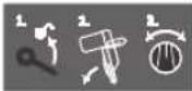
Toka3Ba OTdEnHInTe CbNKn 3a HAcTPOBBAHe Ha bTn Ha CKOcBAHe Bbb BEPTKAnHa paBHnHa.
- Paaxna6epepbkoxBaTkata
2.3aBbptete nIb3raoTO pAmo neko HANBAO - HactpoTe JeknaHaTa 30Ha Ha bTbNa HA CKOcBAHe BbB BepTtKaHn paBHn-Ha BbpXy BbpTtAata Ce pbKoXBAtKa
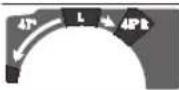
HactpoTe 30HnTe Ha HAKIOH Ha Cpea BBBBepTKaHa paBAHHa BbpXy BbpTaaTa ce pbkOxBtKa:

HaKIOH Ha ZpKpynRnIaNcK HANrBO (45°do 0°)

HaKNoH Ha ZnPKyIaRPNH IINCK HAncHo (0°do 45°)
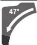
O67a30HaHaHaknoHHaNb3raoTo pamo (-47^ 10+47°
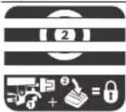
3a HacTPOBaHe Ha npOn3BOHn bTn HA Cpe3a B XOpN3OHTaHa paBHNHa CTeHbT 3a p3aHe Tp6Ba Da MoKe Da CE dBHX CBo6OHO, peCn. 6yToHbT 3a CBO6oHe XoJ Ha 3aBbPTaHe Tp6Ba Da e H3KnIOueH:
-ⅢdIbPnAteNoCTaHedHOBpeMeHHoHaTCHETeHaOny6yToHa3a6loKpAneBnpdHnKaP
Onncahne Ha npodykta n DeHocCTTa

Ipooyete BHNMaTeHNO BCnKyka3aHHN HnHCTpykun 3a 6e3oNaChOCT. IpOnyckn npn Cna3BaHTo Ha INHCTpyKUnHe 3a 6e3oNaCHOCHT yKa3aHnHTa 3a pa60Ta MoT a NmAt 3a IocneCTBHe TOKOB ydap, NoXkap n/ nnTEKKn TpaBMn.
Mon, HmaTe npEbnI n3o6paXeHnra B npEHaT aact Ha pbKOBoCTBTO 3a pa60Ta.
PpeHa3NaeHne Ha eNEKtpOHcTpymEnTa
EnkponHcTpyMeHTeIpeHa3Haueh 3a H3bHnBaHe Ha HAnbXHH HnaneH Cpe3OBe B DpBeCn MaTePnAIn, MOHTnpaH HeNOBnKHO Bbpx ypa6ToH nOT. PnTOBa Ca Bb3MOxHH XOpN30HTaHn bTn HA CKoCBAHe OT-52°do +60KaKTo H BepTKaHn bTn Ha KocBaHe ot 47° (OTJABO) do 47° (OTJACHO).
MoHocTHa eNEKTPOHnCTpyMeHa e pa3yeteHa 3a pa3- p3BaHe Ha TBbPdI Mek DbpBeCeH MaTepnaI, KaKTo I 3a npecOBAHH PNOCKOCTnΦa3epn.
PnH3nOJI3BaHe Ha NOxOJaUu CIPKynpHn DnCKOBe E Bb3- MoXHO n pa3Pra3BaHeTo H aanyMHHBe NpoQnnn n INaCTMaH.
H306pa3eHH enEmeHTn
Homepuhaneto haneementhe heneKtponHcTpymenta ce OTHa do n3o6paKeHHra HcTpaHHnte Cfhyptne.
(1) PpaxoynoBteHaTOp6a
(2) 1oct3a3actonopraBeHaPiB3raaMEXaHn3bM
(3) PboKoXBaTka
(4) 5nokpoBkaHa nycKOBnIpeKbCba
(5) Ppepa3eH KoxyX
(6) ⅢapHnPHo OKaueH npEpa3eKoKxy
(7) Perynpyema onopHa uHa
(8) Onopha WnHa
(9) POnIOxHnIpaTnHa
(10) Cbo6oDhen xoHa bTbna
(11) 3actonopraBaa pkoXBaTKa 3a npoHBOHNbTn Ha cKocBaHe (xOpH30HTaHO
(12) NocT3a npeBapHTenHa HAcTpOHa Ha bTbHa HcKocBaHe (B XOpN30HTaHa paBnHa)
(13) 3aTeRaTeHa pbKoxBaTKa 3a npOn3B0neH bTbJ HaCKoCABaHe (BepTuKaJIeH)
(14) KaHann 3aФнКСиРаHe Na CTAнДapTHN bTn Ha CkoCЯBaHe (xOpN3OHTaHnO
(15) MoHTaXHHN OTBOPN
(16) Ckobaa ydbnkaBaHe Ha onopHaTa nlo
(17) OTBOPH3aXbAaHa
(18) 3axbaaau noct ha ckobata 3a ydbnxkabahe
(19) BuHToBa ckOba
(20) Polka
(21) HnHKaTOp 3a bRbI 3a dHa nHa 3oHa Ha HaKIOHa Ha Cpe3a HApCHO (0^ Do 47^) (BbB BepTKaIIHa paB-HnHa)
(22) Ppepa3Ha nlaactnHa
(23) NtB3rao ce pamo
(24) PerynpaaBnHT 3aDbIb6OuHHHrOrpauHHrTe
(25) DblboounHeHOrpaHnHTen
(26) TpaHcnpTHo 06e3oNaCBAHe
(27) Ckana 3a bfbna Ha ckocBahe (BepTKKaHHO
(28) INHnKaTOp 3a bBbI 3a IaBaTa 30Ha Ha bBbI Ha CKoCBAHe (47^ 0^) (BBB BepTnKaIIHa paBHHa)
(29) ByToH 3a HAcTpoBnBaHe Ha bBn Ha CKoCBAHe 22,5° (BbB BepTKaHa paBHnHa)
(30) 1JIeCTOCTeHEn KIOU6 (6 mm/4 mm)
(31) Ckaa 3a bfa Ha ckocBahe (xopn3oHTaHO)
(32) BbptTtca ce pBkoXbTa 3a HacTpoBaHe Ha 30Ha-Ta Ha bTbNa Ha CKoCBAHe (BbB BepTKaHa paBHnHa)
(33) Maca ha cnpkyjpa
(34) LnpKnypeHnck
(35) AanTepe npaxoynaBHe
(36) OTBOP 3a HxXBpIHa He cTpkyKkTe
(37) BnHT 3a 3actoTOpBaHe Ha 4aHrTe 3a npedna- HnKoKyX
(38) ⅢaHr3a npedna3nHOKoKyX
(39) Ppehen 3akpenBaun (nokpmbna nactHa/npepaehkoxyx)
(40) 3aEN3aKpenBaU6oNT (nokpNBHa nlaCTHa/NpeDnaeH KOxuyx)
(41) Kanak
(42) 3actonopbahehaBana
(43) BnHT C rnaBa C BbTppeWeH WeCTOcTeH 3a 3axBauaHe Ha UnpkyIpaHnCK
(44) 3actonopraaФnaheu
(45) Bbtpewen 3actonopbaaФnaheu
(46) Φικυραῦν BHT ἀς εργημρεγματούρηλιν
(47) DEmnpep
(48) Perynpaun BnHTOBe 3a demnpnaHepTo
(49) OTBOPN3a BHTOBNCTARH
(50) UlaHra c pe36a
(51) brrnoB HndKaTOp 3a bRbI Ha CKoCBAHe (xopn3OH TaHHO)
(52) IyckOB npeKbCba
(53) BnHTOBe 3a noDIOXHkTa INaCTHa
(54)/ Perynipauu BInTOBe 3a OCHOBHa HAcTPOKa 0^
(55)/ (BepTNKaJIeH bIbI Na CKOcBaHe)
(56)
(57) PerynpauBHT3aOCHOBHaHacTpoKa45°(nB BepTKaeneBbTaHaCKoCBAHe)
(58) PerynipaaBnHT3aOCHOBHaHacTpoKa45°(de- cENBepTKkanenbIbHaCKOcBAhe)
(59) Perynpaun BNHTOBe Ha cKaIATA 3a bTbI Ha cKo-CraBaHe (B XOpN3OHTaHa paBHHa)
(60) BnHT 3a cTpeIkata 3a otHTaHe Ha bTbna (xOpH-3OHTaIHO)
(61) Perynpaui BnH 3a CnIATA Ha 3aTaraHe Ha 3aTeRaTeHaTa pbKOXBaTKa 3a npOn3BOJe H bbl Ha CKoCBAHe (BbB BepTNKaIIHa paBHHa)
(62) JIeHTa cbc 3axBaUaHe
TexHHueckn daHHN
| Цркулар за ламперия GCM 10 GDJ GCM 10 GDJ | ||
| Каталожен Home | 3601 M27 04. 3601 M27 0L. 3601 M27 08. 3601 M27 0B. 3601 M27 0K. | |
| Номнадна консуmpлиа мошост W 2000 2000 | ||
| СкорOST на Вьrtene на праzenхов min | -1 | 5000 5000 |
| Ограченина на рисковая тOK ● | ||
| Маса съласно EPTA-Procedure 01:2014 kg 31,6 31,6 | ||
| Клас на зашита | ☐/II /II ☑ | |
| Размeperи на похodд��цркуларни дискове | ||
| Диаметр на циркуларни дис кmm 254 254 | ||
| Дебелна на тялOTO на дисka mm 1,7-2,6 1,7-2,6 | ||
| Мakс. Широчина на рязANE mm 3,2 3,2 | ||
| Диаметр на отвора на дисka | mm 25,4 | 30 |
Dahnnte Baatat 3a HOMHnHn HapexeHne [U] or 230 V. Ppi otKIOHBAuCe HapexeHne n npn CNEuΦnHn 3a OTdEHH NtBnHeHnTe3n DaHHMORAT da Bapnpat.
IOnyctmHpa3MepnHaobpa6oTBaHHaTeaHn(MakcmaHn/MMHMaHn):(Bx.,OnyctmHpa3MepeHaobpa6oTaHHaTeaHn",CTpAHu 321)
HOpmaa3a n3buaBn yM
CTOHOCTHTHe HA EMHCn HA Wym Ca yCTaHOBEHN CbTnACHO EN62841-3-9.
PaBHHIeToAHaTReHepnapHnIyMOTEnEeKTPoHCTpyMeHTa 06bHKHOBeHo e: paBHHIe Ha3ByKOBoTo HAIraHe 93 dB(A); MouHocT Ha 3ByKa 106 dB(A). HeonpeJeHecrK = 3 dB.
Pa6oTeTe c wymo3aIyuIHTenn!
IocouheHOTOBToBApkoBOdCTBO3aekcNIOataaHnBOHa n3bYBaHnI Wm e N3MepeHO NO NOCOeH B CTaNapTHe MeTOI M0KJe Da CnyKn 3a CpaBHnBaHE Ha pa3NHyHn EneKTponHCTpyMeHTn.To eNoXoJIo CbIoTaKa 3a npEdbapTeHa OueHkHa emncnTe Wm.
IocouheHOTn HbOHa n3lbYBaHHaYM e npdeCTaBHTeH0 3a OCHOBHTne npINOKeHHa ENEKTPONHCTpyMeHTa.Ako 6aue eNEKTPONHCTpyMeHTbT ce non3Ba B dpyrN yCIOBNA, c pa3nnuHN paBOTHN INCHPTyMeHTn HIN CLENd HeNo6po NOnDbpKaHe, HNBOTO Ha n3lbYBaHHaYM MoKe Da e pa3NIuHO. Toba 6n MOILO 3HaHTeHNO Da a YBeHHu EmHTnpaHHaYM ppe3 nepoHa nON3BaHe Ha eNEKTPONHCTpyMeHTa.
3a no-TOHOTO OeHbAHe Ha 3JIbUbaHnIy Wm TpRbBa da ce OTHTAT IN nepHOJNTE, B KOHTO eNEKTPOHNCTpyMeHtB TE H3KIOUeH nn paOTo HA npa3eH xoT. TOBa 6N MORNo 3HaHTenHO Da HAmaHn EMHTnpAHn Wm Ppe3 nepHOJa Ha NOn3BaHe HA eNEKTPOHNCTpyMeHtA.
Mонтуранe
N36raBbTe BKNIOUbaHe No HeBHMMaHHe Ha eNEKToHHCTpyMeHTa. N0 BpeMe HA MOHTnPaHTo H npH N3-BbpWbAe Ha KaBnTo N da e DeHocTH No eNEKToHHCTpyMeHTa UencenbT Tp8Ba Da e N3KnOueH OT 3axpaHBaaTa MPexa.
OKOMIIeKToBka
MOnI, BnKTe H3O6paKeHHeTo Ha OKomnIeKTOBkATA B HauaIOTo Ha pbKOBOCTBOTO 3aEKCIIIOatauia.
IpeiJa 3anoHte EeknloataaHa eKeKtpOnHcTpymeHTa DaNNBCHUKN36poEHN NO-DOy enEmeHTn Ca HAnuHN:
-吕Kyap3aJaMnepnC MoHTnpaH nck (34)
-3actonopbaa pkoXBtka (11)
PbKoXBaTka (13) c KOMnIeK 3a 3aKpeBnBaHe
-ynbnaabaacko6a(16)n3axBaauoCT(18)cKOMnJIeKT3a3akpenBaHe
-ПрахоуновтелнаТорба(1)
-WectOteHEn KInou(30)
-BuHToBaCKo6a(19)
Yka3aHHe:OrnedaTe eNeKtpOnHCTpyMeHTa 3a eBentyaJIH NOBpeIi.
Ppei Da npOdbJXnTe H3noI3BaHETo Ha eNEKtpOnHCTpyMeHTA, Tp8Ba BHNMaTeNHO da npOBepTE daII npEpa3HnTe CbOpBxKeHHaII NkO NOBpeEH DeTaN PhHKUHOHpat I3pndHO cBo6pa3HO npEHa3HaueHHeTO cn. PpOBepTe daII NOBHXnTE DetaiNf yHKUHOHPat pABINHO HeCe 3akHbAT II DaII NMA dpyrN NOBpeEH DetaiNl.
BCNKN DetaNN Tp6Ba Da ca MOHTnpAH npABnHO n da n3- nBnHBAT BCNUK yCNOBna 3a 6e3oNa cha pa6Ota.
IbpeHn IpeJna3HH CbOpjxHeH N dTeaJI N Tp6Ba Da 6bDat peMOHTnpaH NIN 3aMeHEnO tKBAHnCpuH Tex HNK B OTOpN3uHcepBn3 a eNEKTPOHnCTpyMeHTn Ha BoW
DOnbHHTeHH HcTpymEnH, Heo6xOaMn 3a MoHTnpaHeto:
-Kpbctata OTBeptKa
- KIIOU cXpaIIOBnK (pa3Mep: 8 MM)
-KpbTbN,BnIKOBnnIeKepeHKnHou(pa3Meepn:10MM 17 MM)
MOnTHnpaHe Ha enEmeHTn
-3BaTe BHNMaTeHBO BCnKBNBKnOueEHN BOKOMnEKTOBKata DaTaN.
-OTCTpaHETBCNHNOnaKOBbHNMaTePnAHINOTeneKTPOHHCTpyMeHTA N BKNIOueHHTBOKOMNNEKTOBkATADeTaIIN.
MOnTnpaHe Ha 3actonopraaata pBkoXBtka (BX.ΦHR. a)
-HabnTe 3actonopBaIaTa pbKoXbIka (11) BCbOTBeHnO TBOp HAD NoCTa (12).
3aTgAte 3actonopbaata pkoBbTaKa (11) BnHaHnpedn p3ane. B npotuBeH cnyau nkpkypanrDnCKMOKe da ce 3aknnn B pa3pa3BaHn DeTaHn.
MOnTHnpaHe Ha pbKoXBaTKa 3a 3actonOpBaHe NOI npON3BOJIe H bTbN (BbB BepTHKaIIHa paBHnHa) (BX. fHr. a)
H3NON3BaIte 3a MOHTaK Ha pbKOXBaTKaT a 3aCTONOPBAHe (13) BKIOUeHHB OKOMNIEKTOBKaT A KOMNIEKT 3a 3aKpenBaHe (uekepeh KIOU,raKa,2noJIOXHN Wai6n).
-ⅡbXHETeOTdENHHTeYacTHB NOKa3aHaTaNocJeOBATeH HOCT(rIONMA NOIIOXKa 7aH6a,pKoXBaTKa,MaJka NOIIOXKa 7aH6a,raKa)Bbpyx BoNTa Cpe36a Bbpyx eEnKTponHCTpymENTa.
-3a no-do6po npedaBaHe Ha cInnata npn 3aTaraHe Ha raKaTa IbxHETe BKNIOUeHnB OKOMNNEKTOBkata UcTeOCTeHEn KIOU (30) npe3 OTBOpNTe BuekePnna KIOU.
-3aterheTe rAikata.
MoTHnPaHa Ha yDbXHTeHtA cKo6a (Bx. mHr.b)
ИЗпОВБа�е 3a мОТЯн УдьнгNTENHATA CКОБА (16) BKNIOUЕСHA BOKOMПЕKTOBKAТA KOMПЕKT 3a 3aKpeNBAHe (2 3aXBaUaUNI NOCTA (18), 2pyKHHN BHTA, 2BHTa CHaKaTka).
-36ytaIte ydbnKHTenHata cko6a (16)doynopB noDxo-daIuTe OTBOPN Bbpxy CTehda 3a p3ahe (33).
-3aBnTe BnHTa C hKaTka Ha pbKa HnBnHO B nOxDoxoJUH Te OTBOpN.
-Noctabete Bbpxy rnaBata Ha BNHTa C hakatka 3axBaua-
-ФИКСИРаTe 3axBaUaUaUNI NOCT(18)C npyKHHNnBnHT.
-YBENHETe3axBaUaUaTcNHaHa3xAbaUaUuNIOCT(18) KATO 3aTeHHTeIpyKHHINBAHTC BKNIOUeHNIBOKOMNI KEKTOBKATA WECTOCTEHEKNIOU (30).
CtauHapHo HnMo6HNO MOHTpaHc
3a ochrypbahe Ha cnrypha pa6ota c enektpoHHctpyMeHTa, npedn da ro h3non3BaTe, Tpa6Ba da ro MOHTnPate Ha paBHa n CTabHnHa pa6Otha NOBbpxHOCT (Hanp. pa6oTe3rax).
MoHTnpaHe ha pa6Otha nobbpXnOCT (Bx. qHr. c1)
-3actonopete enektpounhctpymeha cnoxdoian BNHTOBn CbeHHHnKbMaPabOTHaTPOBbpXHOCT.3aTa3n ceIcnykAT OTBOPHTE (15).
HNN
-3actonopeTe eNEKtpoHnCTpyMeHTa C 06NKHOBeHN BnHTO BnCKO6N, KATO r0 3axBaHete 3a KpaKaTa KbM pa60Thata NOBbpXHOCT.
MOnTHpAne Bbpxy pa6OTeH cTeHd Ha Bosch (Bx. qnr. c2)
(GTA 2500 W, GTA 3700, GTA 3800)
CTeHIOBete GTA Ha Bosch ocnHypBaTc HpyhO 3axBaUaHa He eneKTPoINHCTpyMeHTA KbM BCaKaBA NObpxHOCT 6nAoDapeHHe Ha peryInpyeMITE cN IO BnCOuHa KpaKa. OnpHITe NOBbPxHOCTNa DeTaAHIne Ha CTeHIOBete CnyKAT 3a IPOINPAHe HA Dblr DeTaJIN.
PpoetyeBCnKn npnoxehn KbM cTeHda npeynpekdeHHn yka3aHH. Hecbo6pa3BaHeto c npeynpekdeHHTA n Hecna3BaHTo Ha yka3aHHaTAMoratJaMMaT3a NocneCTBNE TOKOB ynap, NOXap N/NN TpaBMN.
PpeHn da MOHTnpaTE eneKTPoHNCTpymEnTa, crNo6ete BHMaTeHNO n npabHnHO cTeHa. PpaBnHToC rno6BaHe Ha CTeHda e BaxHo, 3a Da 6bne H36gHnTa onacHocT Ta OT BHe3AnHTo My paNaJaHe NO BpeMe Ha pa6ota.
-MoHTnpaTe eEnKtPOINHCTpyMeHTa KbM CTeHda,IOKaTOe B No3nua 3a TpaHCnOpTnpaHe.
Cnctema 3a npaxoynaBHe
PpaxOBe,OTdEJIaIc Ce npn 6pa6oTbAHeto Ha MaTepeHAni KaTO cbbpkaaOnOBO 60N, HAKON BNDObe DbpBecHa, MHepani MeTANMORAT Da 6bDat ONaCHN 3a 3dpaBeTo. KOHTaKTbTdo KOKATAH NIN BmWBAHETo HA TAKBa PpaxOBe MORAT Da ppeIN3BnKAT aeprHuN peakun H/nn 3ab0JraBaHna Ha dNXATEHNTe PbTHUa Ha pa6oTeuC eEnkTPOHCTpyMeHtA nn HAmpaUNCe HabN3O nua.
OnpeneHn npaxOBe, Hnр.OTdienaIte ce npn 6pb6oBaTBeHa 6yK nIb6, CE cHTaT 3a KaHcpeoreHHN, OOCbeHO B KOM6nHaunC XHMKnAaN 3a TpeHpaHe Ha DbpBecnHa (Xpomat, KOHcepBaHTn nIp.).DOnycka ce 6pb6oTaBHeTo Ha CbDbPkaaN a36ct MaTePAHn CaMO OT cbOTBeTHO 6byeHN KBaHnФuHpaHn Nla.
-ПО ВБЗМохностиЗПОЛЗВаITE NOДХОДЯЗа 3a OБрабOTВАНЯ MATEРпAN CNTЕма 3a ПрахоулавгHe.
- OcnrypraBaTe Do6po npobetpaBaHe Ha pa60THOTo MRCTO.
-Преничва ce Използвано Ha дnxателha Macka cФнлtp ot Knac P2.
Cn3BaIte BaIIHnTe BbB BaIaTc TpaHa 3aKoHOBn pa3nope6n, BaIIHn npn o6pa6oTBaHe Ha cBoTBeTHNe MaTePna.
1368BaTe HATpynBaHe Ha npax Ha pa60THoMrcTo.
PpaxbT MoXe IecHO da ce caMOBb3nnaMeHH.
PpaxoynaBHeTO MoKe da 6bDe 6noknpaHO OT npax,CTbproTHHH NtOKbPTEHNOT TaHa napueHa.
-ИЗКИЧЕТЕЕNEKTPOINHCTPМЕNTAиИЗВадETe UENECELAOT KONTAKTA.
-3aKaTe,doKaTo npKpynPaHnT Dnck Cnpe HnBnHO.
- OtkpniTe nOCTpaHete npnHnHaTa 3a 3anyBaHeto.
Co6CTBeHa ChTeMa 3a npaxoynabnahe (Bx. mHr.d)
3aJeCHO c6bHpaHe HA OTeJIeHNHTe CtpyKKn H3NoJ3BaIte BKIOUeHaTa BOKOMIIeKTOBkAta IpaXOyIOBHTeHa Top6a (1).
-BkapaTe n 3aBbptTe npaxoyNoBtEnHata Top6a(1) Bbpxy aanTepa (35) Taka, ue uHHTyeTo Ha aanTepa da 3axBaHe c npeuPakBaHe OTBopa Ha npaxoyNoBtEnHata Top6a.
IIO Bpeme Ha pa6oTa npaxoyNoBHTenHata TOp6a He Tp86Ba Da Bn3a B CbnpKOCHOBEHc C NODBxHHTe DetaiHa eNEKTPOHNCTpyMeHtA.
H3npa3BaIte CBOEbpemEnHO npaxoyNoBtEnHaTAtop6a.
PpOBeBaTe H NouchBaTe npaxoyNoBHTenHata Top6a cneBcKa ynoTpe6a.
3a da npeoTbpaHTe onachocTta OT noxkap, cne p3aHe Ha anyMNHeBn CnnaBn NouchBaTe npaxoyNoBHTenHata Top6a.
BbHnHa cHcTeMa 3a npaxoynabRe
3a acnpaunKa KbMa aanTepa 3a npaxoynabHe (35) MoKeTe Da CbpxKeTe H Mapky Ha npaxocmykaUka (0 mm).
-CbpxKeTe MapkyuHa npaxocMykaKaTa c aanTepa 3a npaxoynaBHe (35).
H3non3BaHata npaxocmykaTpa 6Ba da e npiroda 3a pa-6ota c o6pa6oTBaHn MaTePnAn.
Ako npa pabota ce otDena oocbeNo BpeEn 3a 3npaBeTo npax nnn KauepeoreH npax, nno3BaTe cneuaan3npaHa npaxocmykaKa.
TouncBaHe Ha npaxoynOBntHHn aadTep
3a ocHpyraBaHe Ha ONTUMaHa CTeHn Ha npaxOynaBHe aadantepbT (35) Tp6Ba nepoDnHn Da 6bDe nouCTbaH.
-3dbpnaTe cbc 3aBbPaThe npaxoyNOBtHnHa aanTep (35)OTOTbopa3aN3XbPnHe Ha CTbProTHnTE(36).
-OTCTpaHete CTbProTHH N OTKbPTeHN NapueHua OTo6pa60TBaHHA Detai.
-NotabeTe OTHOBc 3aBbPtaHe npaxoyNOBtHnna aanTep BOTbopa 3a nXbPnaHe Ha CTbproTNHte,doKaTo 6bJe 3axBaHaT CnpeUpaKaBaHe OTaDbpkaunn npbcTeH Ha OTbopa.
CmHa Ha nhpkynnpn nnck (Bk. qnr. e1-e4)
Pepn H3BpBaHe Ha KaKBTo H da e DeHocTH No eNekTPOHHCTpyMeHTa H3KNHOBAIte ⅢeNceTa OT 3axpaHbAaTa MPexa.
PnMOHTnpaHToHaUpKynpHnDnckpa6oTe c npedna3n pbKaBn. PnDOnnIp DouKpynHn DnCK CbueCTByBa OAnChOCT Da ce HapaHHe.
H3no3BaTe cMo pexeun DNCKOBe, uHTo MaKcHmAnHO dOnyCTMa CKOpOCT Ha BbPteHe e NO-BHCOKA OT CKOpOCTTa HA BbPteHe Ha npaeh XoJ ha Baun enEkpOHCTpyMeHT. H3no3BaTe cMo UHPKUJIAPHN DnCKOBe, KOHTo CbOTBeTcTBaHa NOCOeHnTE B TOBA pbKOBOCTBO 3a EKCnIOaTauN DAHHn n Ca IINITAHn PO EN 847-1 n o603HaueHn n CbOTBETHnHaHH.
H3non3BaIe cAmO nCKOBe, KOHTe ne npenopbUbAT OT npoH3BODHTeHa eEeKTPoHHCTpyMeHTa H ca npDxOJa7u 3a 06-
318|Блгарский
pa6oTbaHHa oBac MaTePnAn. Toba npedotbpaTBA npepraBaHTo Ha 3b6nte npri pR3aHe.
DEmoHTnpaHeHaUHPKpynApHHNAnck
-Noctabete eNEKTPoHHCTpyMeHTa Bpa6ToHa no3nua.
-PaXna6eTeΦKcnpaunBnHT(37)CWeCTOCTEHNN KIOU(6mm)(30),DOKATOaHrata(38)HeMOKe da ce OTkau CBO6oHO.
-Pa3BnTe 3akpenBaun6oT(39)(npn6n.Ha206opota)cweCTOeHHNkIou(4mm)(30).He pa3BnBaTe BNHTaDOKpaJ.
-Pa3BnTe 3akpenBaun6oT40 (npn6n. Ha 6 o6opota) C wecToCTeHHN KIou (4 mm) (30). He pa3BnBaIte BnHTa DOKpaJ.
-ИздьрайтЕ HanpeДи Надonyи ИЗВадеТе Kanaka (41) ot 3aCTOnOpЯBaшЯ BnHT (40).
-Haknohepe npa3nnaKoxyx6Ha3aIro 3apbXTe Ta3n no3nua.
- Okaetae eHNNIOTBOP HaaHHTe (38)Ha 3actonopBa-
LIIBAHT (40).
Taka shapnphO kauehnI npedna3eH KOxyce 3abp
Jb BTOBPOHO NOXKeHne.
-3aBbPTe BnHTa C rIaBa C BbTpEweH WeCTOcTe (43) C WecTOcTeHHN KJIou (6 mm) (30) HATNCHeTe EINHO MeHNO fHKcapHeTo Ha IINHdeNa (42), DOKATO He ce fHKcapa.
-3aPbXTe 6yToHa 3a 6nOKnPaHe Ha Bana (42) HATnCHaI paBnTE BnHTA (43), KATO rO BpTIne NO NocKa Ha qacOBHnKOBaTa CpeNka (naBa pe36a!).
-Демонтураитzeясторогашия Флamede (44).
-ИЗБАДЕТЕЦИКУПЕРПИДСК(34).
MOnTnpaHe Ha zHpKyIaPnHa dNcK
PnMOHTnpaHe BHHMaBaIte NocOKaTa Ha p3aHe Ha 3b6HTe (o3HaueHa CbC CTpeKbBpXy UHPkyIpaHn IINCK) Da CbBnaJa c NocOKaTa Ha CTpeKbTA BbpXy npedna3Hn KoxyX!
AKe e Heo6xOaHMo, NouchTe BCnKu DeTaun, KOnTo Ue MOHTnPate.
-NotCtBaTe HOBINI CHPKynpaH ENCK HA BbTpEaHHa 3aTo-nopraBauΦlaHeu (45).
-MoHTnpaTe 3actonopBaunuФnaHe44)nBnHTaC 10CTeHHaTnBa(43).HaTncHe6yToHa3a6nOKpa- He Ha Bana(42),DOKaTO3axBAhe Bana C npeUpaKaBaHe,H 3aTeHETe BNHTaC WcTeOCTeHHaTnBa,KATO rBbPTNTE 05paTHo HA yacOBnKOBata CTpeNka.
-OTkauheuHaHHTe(38)OT3actOnopBaunBnHT(40)cnyCHeteOTHOBOHaDonywaHPnOOKaueHn npedna-3EHKOxyx(6).
-BkapaTe Kanaka (41) OTHOBo noI 3actOnopBaunn BHT (40).
-OTHOBO 3aTeHHeTe 3dpaBO 3actOnopBaunte BnHTOBe (40) n (39).
-BbpHete 38)do pboHOHaaHaTAtmno3nua H3aterHeTe OTHOBo Ha pbKa 3actOnopBaunu BHT (37) C KIOUc BBtpeue HeecTocteH (6 mm) (30).
Pa6ota c eNeKtpoHhCTpyMeHTa
PpeHn3BbPwBaHe Ha KaKBHTo H da e DeHocTH no enEeKTPoHHCTpyMeHTa N3KNIOuBAIte UeNCeTa OT 3axpaHbAuta MpeXa.
TpaHcnpToHO o6e3oNaCBAhe (Bx. hA)
TpaHcnpTHo 06e3onacBaHe (26) yneChra npehacHeTo Ha eneKTPoHnCTpyMeHTa do pa3nUHN pa6OTHN pIoouaKn.
Ocbo6oxkaBaHe ha eneKtponHcTpymenta (pa6oHa no3nua)
-HaHcHeteJeKOHaOnyPiB3raUTo pAmo (23),KATO ro DbpxHe 3a pbkOxBaTKaTa (3),3a da ce ocbo6oN 6yToHa 3a 3actOpRaHe npn TpaHCnpTnpaHe (26).
H3dbpnaTe 6yToHa 3a 3actoOpBaHe npH TpaHcnpTpaHe (26)doKpaHabbH.
-Повдгнete6abHnHaRopeпьзraTo ce paMo (23).
БлokнраеHa eNeKtpOnHcTpymenta (no3nua 3a TpaHcnpToHpahe)
-36ytaTe PnB3raUTo ce pAmo (23)doKpaHaaad Hro 0e3oNacTe B Ta3n No3uH.
- Ppekapaipe pamoHa nIb3raaoto ce pamo DoToNKoBa HADony, ye TpaHcnpTHOTo oBe3onacBaHe (26) da ce npHTNCHE DOKpai HAbbTpe.
Дугун yka3aHHa: TpaHcnpTupaHne
3actonopbahe Ha nIb3raaTo ce paMo
Пььзгд Мханньм Ha paMTo (23) можда 6ьд ecTOnOpEH C NOMOHTa Ha loCTa (2). ПиTuBa ca Bb3MOxHnДBE NO3NIM Ha IIb3raUTo ce paMo:
-ПльзгашоTo ce pamo e n3MecTeHo dOKpaHnaz (3a YenHn Cpe3OBe)
-ПьзгашоTo ce paMo e H3TerHeNo DoKpaH anpei (aKOMnKaTHa TpaHCnOpTHa No3nU)
Ocbo6oxdaBaHe Ha nIb3raaTo ce pamo (Bx. qnr. B1)
CnEoocbo60kaBaHe Ha nIb3raIoTo ce paMo ueJIHT MExaHn3bMa IIb3raHe (23) e roTOB 3a paOba.
-HaTncheTe 3acToOpBaunIocr (2)doynopHaOny.
-3actonopBaunT KINH Ha 3actonopBaunI NOCTOCBO60kdaBdTe DoHN CTaBN Ha Nb3raUTo ce pAMO.
OchrypBaHe Ha nIb3raIoTo ce paMo (Bx. qHr. B2)
Пьзraцоce paMo e n3MecTeHoДOKранHa3aI:
-Ппмсетete nmb3raauTo ce pamo (23)doynop hazan.
-TaKa DBeTe TOpHN ⅢaHn Ha CtBaTa Ha Nb3raIooTo Ce pamo Ca HnpaBENn Ca 3aTBopeHn.
-ⅢaBpnaTe 3actonopBaunnnoct(2)Harope,doKATO 3actonopBaunr KINH 3actaHE MeKdy DBeTe DOHN HaaHn Ha CTaBaTa HA Nb3raUTo Ce pamo.
-TaKa n3MeCTeHTo Do KpaIHa 3aHa No3uNra Nb3raUc ce pAmO (23) e3actOnopeHo.
ПьзгоTo ce paMo e n3mecTeHo Дкрй HanpeD:
-ИздрпайтпьзгашоTo ce paMo (23)do ynpнанр.
-TaKa nIb3raIaIHT mExaHn3bMe nI3TeIeN dOkpaI.
H3bpaHte 3actonopbaaHnOCT (2) HArope,doKato 3actonopbaaHT KINH 3actaHE MeXy DBeTe DOHNu HA CTaBaTa Ha Nlb3raUTo Ce paMo.
-TaKa H3MeCTeHTo Do KpaHa npEHa No3Hcna Nb3raUO ce paMo (23) e 3actOnopeHo.
IoproToBka 3a pa60Ta
YdbnkaBaHeHaCTeHa3aP3aHe(BK.ΦHr.C)
IbIg DeaIIN Tpa6Ba da 6bDat noDnnpaHn B Cbo6oHnN Kpa.
PnH3pa6oTbAe Ha Cpe30Be NoHaknoB XOpH3OHTaHa H/Inn BepTKaHa paBHnHa B 3aBNCMOCT OT NOCOKaHa p83aHe Tp6Ba Da H3DbpNaTe HABhN, pcen. HanbHNo Da demOHtnpaTe NaBata HIN daChata perynpyema OnopHa WnHa (7).
| bГЛ Ha cKOCaBa- He bB BepTH- KaIIha paBHHa | bГЛ Ha cKOCaBa- He B XOpH3OHTaI- Ha paBHHa | |
| 0°-47° (BIЯBO) | ≤ 44° (BIЯCHO/BIЯBO) | -Pa3xla6ete ΦИКСИРашпяВИNT(46). -N3ДьрайтЕ дOKраH habвн ЛЯВATAperулірема onopнашиHA(7). |
| 0°-47° (BIЯBO) | ≥ 45° (BIЯCHO/BIЯBO) | -Pa3xla6ete ΦИКСИРашпяВИNT(46). -N3ДьрайтЕ дOKраH habвн ЛЯВATAperулірема onopнашиHA(7). -N3Вадete наrope perуліремао onopнашиHA. -N3Вадete ФИКСИРашпяВИNT(46). |
| 0°-47° (BIЯCHO) | ≤ 44° (BIЯCHO/BIЯBO) | -Pa3xla6ete ΦИKCSIPAshNBAHT(46). -N3ДьрайтЕ дOKраH habвн ЛяСНа ретулірема onopнашиHA(7). -N3Вадete наrope perуліремао onopнашиHA. |
| 0°-47° (BIЯCHO) | ≥ 45° (BIЯCHO/BIЯBO) |
PerynnpaHaJaemnpaHToHaNb3rauTo ce pamo (Bk. Hr.F)
Pb3raaHmexAHn3bMa pAmTo (23)eHaCTpoeB 3aBOda-ppoON3BOOnTeN H CbCTOHNHe HaIOCTABKa DBHXKeHNeTo My He Ce demnnpa.
Moxete da Hactponte demnphihaTo Ha nIb3raun MexaHn3bM cbo6pa3Ho JenaHneTO Cn NOMOuTa Ha demnpepa (47):
TBbpO-KoHTpOJIpaHn pa60THn DbIXeHna; Meko-6bp3n Cpe3OBe.
-Pa3BnTeDbatapeynpaunBHTa(48)cIecToctEHNnKIOU(4mm)(30)3aNo-MeKOdEmnpHpaHe
HNN
-3aterHeteBataperylnpaun BNHTa(48)3a no-Tbbpdo 備nnpahe.
3actonopbaheHaTeaia(BK.ΦnG)
3aOCHyprBaHeHaONIMaHnCHArypHoCTHa p60Ta Tp6Ba BHHaHJa 3aactOnOpBaTe TaHJa.
He 6bpa6oBaTaeTain, KOTo ca TBbpDe MaIKn, 3a da 6bDat 3actOnOpEn.
-ПнТСНЕ ДЕТалЯ 3ДраВКБМОпОРHAТА WHHA(8).
-BkapaTe BKNIOueHATA BOKOMNNEKTOBkata BHTOBACKo-6a(19)BEINOTnpEbnDEHnTe3aCENTAOTBOPN(49).
-3actonopete 3npaBO DeTnna, KATO Bbptnte BNHTOBata UaHra (50).
HactpoBaHe Ha XOpH3OHTaIe H BeptnKaIeH bTbHa HAcN0H
3a ocnhypbahe Ha npceun3Hn CpeoBe cneH nHTeH3HBHO H3- non3BaHe Tp6Ba Da npOBepBaTe OCHOBHte npaMeTpHa eNEKtpOHnHCTpymEtHa nPn Heo6xOIMocT da rN KopnnpaTe.
3a cetaTtpr6Ba da HMaTe OINH CbOTBeTHHe CNEuHaHn3paHn HcTpymeHTN.
Ta3n DeHocHT 6bHe H3BbPseHa 6bp30 N KaueCTBeHO B OToP3npaH cepBn3 3a eEnkTPOHNCTpyMeHTn Ha BoI.
3aTgAte 3actonopraatapbkoBtka(11) BnHaHnpedn p3ane. B npoTHBeH cnuya unpkynpHnT nCKMOKe da ce 3aklinH b pa3pa3BaHH DeTaHn.
HactpoBaHe Ha bTbHa cpe3a B xOpn3oHTaHa paBHHa HactpoBaHe Ha bTbHa Ha KaIOH XOpN3oHTaHe CTahdApTeH (BX.ΦHr.H)
3a 6bpy30to H npeun3HO hAcToBaH e Ha YecTo n3non3BAHN bTn H XOpN3OHTaEN HAKNoB Bbpxy CTeHa 3a P3aHe ca npEnBvDeneH KaHaH (14):
HANBAHOHaACHO
0^
45°;31,6°;22,5°;15°15°;22,5°;31,6°;45°;60°
- Ocbobode3actonopBaata pkoXBtka (11),ako e 3aterhata.
-ⅢaBpnaIteNoCTa(12)H3aBbPTeTEcTHe(33)HaJIBO HnHADCHODoKeNaHHaPe3.
320|Бьлгарский
-CneTToBaOTnycheTeNoCTa.TpA6BaJa yceTHeOTyETNBOToPipeuPaKaBaHe, C KOEtTOBnHa3Ba Hnape3a.
- OTHOBO 3aTeHHe pBkoXBaTkaTa (11).
HactpoBahe Ha npon3Boneh bTbHa CKoCBAhe B XOpH3OHTaHa paBHnHa (BK.ΦMr.1)
HaKnHbT Ha Cpe3a B XOpH3OHTaIIHa paBHHa MoKe da ce HacTpON BmnaIa3oHa Do 52° (HaJIBO) n 60° (HaJIcHO).
- Ocbobode3actonopbaata pkoxbatka (11),ako e 3aterHata.
-ⅢaBpnaTeNoCTa(12)HEOHBpeMeHHoHaTHcHteHaDony6yToHa3a6nOKupaHe(10)BnpdHnKpaI.
CToBaNoCTbT(12)ce3actonopraHa pa60THnT nnot e NOBnKeH.
-3aBbptete CTeHda 3a pR3aHe (33) 3aФИКСИРацета Cko-6a HANBO HnHnAHaCHO, DOKATO CTpeKATA (51) He noka-ke JxenaHn XOpN3OHTaEN bTbHn Ha KaIOH.
- OTHOBO 3aTeHETe pbKoXBaTKata (11).
-3a da oCBO6OHTe OTHOBIOCTa (12) 3a HAcTPOIBaHE Ha CTAHdAPTHN bTIN HA CKOCBAHe),H3DbpNaTe IocTa HarOppe.
ByToHbT 3a 3aCToOpBaHe Ha IocTa (10)OTCKaA OTHOBO B IIpBOHaHaHnHaTc HIO3uNn IIOCTbT (12)MOKe OTHOBO Da BnHa n Da Ce 3axBa u B N3p3aHnTe 3a CenTa KaHaII (14).
HactpoBaHe Ha HAKNoHa Ha Cpe3a BbB BepTKKaHa paBHnHa
HaKIOHbT Ha Cpe3a BBB BepTKaJIHa paBHHa MoKe Da Ce HAcTpO BmAna3oHa Do 47° (HaJIBO) u 47° (HaJIcHO).
3a6b30n npeun3no perynipane Ha yecTo nbtn n3non3BaHnTe p3aHn nohaknO BvB BepTknHa paBnHa ca npdeBnDEHN ORpaHnHTeN 3a brrnte 0^ 22,5n45n47°
HacpoKaHa NABaTa 30Ha 3a HAKIOH BbB BeptHKaHa paBHnHa (45°do 0^

-Издрпаг Te DOKрай Habьн Лвata perулрума onopha ⅢHа7.
- Ocbobodete 3actonopbaata pkoxbatka (13).
-HaknohepepAMOTo(23)HaHCTpyMeHTa3a pbKOXBaTKaTA(3),DOKATOHHNKaTOPbT3aBbI(28)He NOKaKe JeJAHIN BEPTHKaJIeH bBbI Ha CKOCABaHe.
-3aDpBkTe PnB3raIoTo ce paMo (23) B Ta3n N03nua 3aTeHETe OTHOBO pBKOXBaTKata (13).
CnataHa3aTaraHeHa pBkoXBatkata Tp8BaDa 3aDbpka
nB3raOc ce paMo 3dpaBO nCrypHO npn PPOH3BOJeH
bBn Ha CKoCABaHE BbB BEPTNkAlHa paBHnHa.
HactpoKaHaJaChaTa30Ha3aHaKIOHBBBepTKKaJIHa paBHnHa (0^ do 45^) (Bk.Φnr.J)

-ИздрпаTeДOKран Habьн ДяСЧаТаperулmpуema onopHaшиHA(7).
- Ocb6o6eTe 3actonopBaata pkoXbTaKa (13).
-HaknoheTe nIb3raTo ce pAmO (23),KATO rO dbpxKeTte 3a pbkoxBaTKaTa (3)NeKO HAIABO OT No3nUHTa O" n 3a
47°
BbPTe pbKoBtKaTa (32),doKaTo DoCTnHTe JeNaHHaHKIOH BBB BepTKaHa paBHHa.
-HaknohepepaMOTo(23)HaHnCTpyMeHTa 3a pbKOXBaTKaTA(3),DOKaTOHHNkAToPbT3a bBn(21) He NOKaKe JeNaHn BEpTHKaHeBbLn HaCKoCBAHe.
-3aPbKTe PnB3raUTo ce paMo (23) B Ta3n No3nua 3aTetHeTe OTHOBo pkoXBaTKata (13). Cnata Ha 3aTgAne Ha pbKOxBaTKata Tp8Ba Da 3aDbpxa nB3raUO ce paMo 3dpaBO nCnpyHO npn npon3BOJeH bBnHa CKoCABaHE BbB BepTKaJIHa paBHINHa.
HacpoBaHe Ha cTaNdApTeH BeptnKaeneH HAKIOH Ha cpe3a 0^
3a da MoKe No-LecHo Da ce HAcTpOHa cTaHApTeH BepTKaJIeH HAKIOH Ha cpe3a 0^ ,BbPTaIaTae pka (32) ce fHKnpa B 3oHa Ta H BepTKaIHN HAKIOH HAIBO.

- HaKIOHETe nIb3raOTo ce pAMo (23) OTIACHO Ipe3 NO- 3nurTa 0^
HactpoKaHaaJnata3oHa3aHaKIOHBBBBePTHKaJIHa paBHnHa (-47^ 10+47°
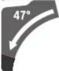
-NTerTneDBeTe npemecTbaun ce onopn HHHH (7)doKpaHabh.
- Ocb6oJeTe 3acToOpraaTa pkoXBAtka (13).
HaKIOHETe Nb3raUTo ce pamo (23), KaTO ro IbpxkHTe 3a pbKOXBaTKaTa (3) IeKO HAIyBO OT IO3NtIa O' n 3aBbPTe PbKOXBaTKaTa (32),IOKATOOCTINHe JKeNAHnHaKLOH BvB BEptIKaHaPaBHnHa.
HaKIOHOHe HAIABBO HIN HAJRCHO IIb3raUTo ce pAMO (23), KATO IOBpKInTe 3a pbKOXBAtkata (3), DOkATO CTpeNKata (28) INI (21) NOKae XeJenaHnBepTnKaJe bRbJI HA CKOBAHe.
-3aPbXTe NIIb3raIoo Ce pAmO (23) B Ta3N No3nua 3aTeHHe OTHOBpKoXBaTKaT(a13).
CnataHa3aTaraHe Ha pBkoXBaTKaTa Tp8Ba Da 3aDbpxa nnb3raio Ce paMo 3dpaBO HcHpyHO npn npOn3BOJeH bbl Ha CKoCABaHE BbB BepTKaHa paBHHa.
HactpoBaHe Ha cTaNdApTeH BepTHKaNeH HAKNoH Ha cpe3a 22,5° (Bx.Фнr.K)
N3aBpnaTe OOKpaHaaadbyToHa 3a HactpoBaHe (29) n ro 3aBbPTe Ha 90^ .CneTOBA HAKIOHE Tb3raIoTo ce paMo (23) KaTo rO DpbKHTe 3a pbkoXBtKaTa (3),doKaTo yceTHe OTcETnBOTO ppePpKaBaHe Ha Nb3raIoTo ce paMo.
IyckaneBeknloataua
BknouBaHe (Bx. qnr. L)
-3a BkIOUOBAHe Ha eIeKToPONHCTpyMeHTa nbpBO npemecTe 6nOKIpOBKaT4 (4)do cpeTaNcE ToBa HATNCHe Te NcKOBn PKeBcBaY (52) nro 3aDpBxKTe HAChat.
Yka3aHHe: Iopadn Cb6paKeHHa 3a ChrypHcT NyckOBnI npekbcBa (52) He MoKe da Bbde 3actOnOpEn BBB BKIOue-
HO NOIOKHeH H No BpeMe Ha pa60Ta Tp86Ba Da 6bDe IbP-XaH HAITCHAT.
N3KJIIOUBAHe
-3a n3kn0uBaHe OTnycHete NyckOBn npkebcbau (52).
OrpaHnueHne Ha nycKOBnTOK
EneKtpoHHata CnCTema 3a OrpaHnuBaHa Ha NycOBnTOK OrpaHnuBa MoUHocTTa PnP BkIOuBaHa He eNEKtpoHHcTpMyMeHTa H No3BOLRA 3axPaHbHeTo My Da Ce N3BbPbBA O T MpeXn Cnpedna3HTeN 16 A.
Yka3aHHe: Ako BeHaRa CnE Bd BkNIOuBa He eneKToHNCTpyMeHTb 3aNoUba Da paOTo Ha MaKcMAnHH O6OpOT, e NobpeH MoynbT 3a OrpaHuaBaHe Ha NyCKOBn TOK. EneKToHNCTpyMeHTb TpA6Ba Da ce H3npaTH He3a6aBHO B OTOpN3panh CepBn3 3a eneKToHNCTpyMeHTn. Adpecn: KIneHTcka cnyKa n KOHCyNTaun OTOHoC yOntpe6ata.
Yka3aHn 3a pa60Ta
06xynyka3aHHa p3aHe
BnHaH 3aTgAraTe 3actonopBaUata pkoXBAtka (11) 06TAAHATA pbKOXBAtka (13) npdrp3aHe. B npotIn- Beh Clyuayi upkyIrpHnRT DnCK MoKe Da ce 3aknnn B pa3pa3BaHH DeTaII.
BHHaH 3aTgAraTe 3actonopBaAsaTa pkoXBAtka (11) H 3axBaAsaNoCT npEn py3ane. B npOTHBeH cIy-ayu npKpypHnT DnCK MoKe Da ce 3aklnn B pa3pa3BaHn DeTaN.
BnHaH, Korato pa3pa3BaTe, npEaBapHTenHO Tp6Ba Da ce yBepHe, ye no znaTATA dbJnxHa Ha cpe3a uKynarHnT dNc K HA Ma da Donpe onOpHata uHa, BnHTOBnTE cKoBn HnDpyrEneMeENTn Ha eNkTPoHNCTpyMeNTA. OTCpaHete EBentyAnHO MOHTPAH NOMOuH NOpH Hn CbOTBeTHo TN PpeMeCTe.
PpeIa3BaIte pekeuia DNCK OT pe3KN HATOBapBaHn I yapn. He n3naIte pekeuia DNCK Ha CTpaHNo HATOBapBaHe.
Pa3pa3BaIte cAmo MaTePhaHn, BKnIOueHbONcHaHeTo Ha npEHa3HaueHHeTo Ha eNEKtponHCTpyMeHTa.
He 6pbOBAIte DeOpMnpaHn DetaII. DetaiNbT Tp6Ba Da HMa BnHaI npab pb6, C KOIT O da ce onnpa B onopHaTa 1HnA.
Cbo6oHnTe KpanuHa nBnIn N TeKKn DeTaN Tp8Ba da 6bDat noDnnpaHn no NOxOJaHauH.
Ybepete ce, ye shapnHPO OKaueHnT npednaeH KOxyfynKuOnHpa HOpMaHNO MOKe da Ce DnBxN CBO6oDHO. PnCnyckaHe Ha pAMOTO HA eNEKTponHCTpyMeHTa HAnOly npedna3HNr KOxyx Tp8Ba Da ce OTBapr. Pn NOBnIaHe Ha pAMOTO Ha eNEKTponHCTpyMeHTa HArpe npeJnA3HNr KOxyx Tp8Ba OTHOBo Da ce 3ATBapr HAD UnpKyIrpHnI dNck N da c3actonopRa B HAI-TopHa No3uIN.
Pto3nHa onepaTopa(BK. mR.M)
He 3actabaIte B eHa paBHHa C uNpKynnHn Dnck nped enektponHcTpymenta, a BnHar nBCTpaHn. Taka TaIOTO Bn e npdna3eHO OT eBHTyaneH oTKat.
IpbkTe npbctHe npbceTe Hn Ha 6e0nacHO pa3OTHNE OT BbptAHTe Ce enEmeHTHa eNekTPOHCTpyMeHTa.
-He noctabnIte pbcTe cHnpanko nped paMTo Ha enekTpOHnHCTpyMeHTa.
CMHaHa BNOKKTte (Bx.ΦnR.P)
UpeBHeHTe BNOKKn (9) MoRAT CneI npOdbNkHTenHa pa6oTa C eNEKTPOnHCTpyMeHTa da Ce H3HOcT.
3aMeHnTe NOBpeENBLOKKn.
-Пoctabete eelenktponHCTpymehaВ pa6OTHaNo3nZna.
-Pa3BnTE BnHTOBete (53) C WECTOCTeH KIOU4 MM 30) N DEMOHTPaTe CTAPITE BLOXKN.
-IOCTaBeTe HOBaTaIaCHa BnOJka.
-3aterheTe BNOKkata C BNHTOBeTe (53) NO BB3MOXHOCT NO-HaACHO, Taka ue cnpkyIapHnT nCK Da He JdoNHPa NO cIaTbIKNHa Ha XOda CN npn H3terHe.
- NOBTOPe aHANOrHuHO CbUTo 3a HOBaTa JRABa BNOJka.
DonyctHMpa3MepnHa06pa6oTBHnIeTaH
MakchmamEn pa3MepeHa DaTayla:
| Бтбл На СКОСЕВА НЕ В XОПИЗонтД- на paBHINHA | Нakpoн На срета Бвв Бернкална paBHINHA | Висоуннахш- рочна [mm] |
| 0° 0° | 80 x 306 | |
| 45° 0° | 80 x 216 | |
| 0° 45° (Влино) | 54 x 296 | |
| 0° 45° (Вдясно) | 30 x 296 | |
| 45° 45° (Влино) | 54 x 208 | |
| 45° 45° (Вдясно) | 30 x 208 |
MHHMaHnIeTaHn(=BCNUKnDeTaHn,KoHTO MoTgDa 6bDat3axBaHaTHC BKNIOUeHaTBAOKOMNIEKTOBkata BNHTOBACKo6a(19)BnBOHnBnCHOOTuNPKynpHnIuck):145x306MM(dbNxHnXu npHa)
Makchmanna dbn60nuHa ha p3aHe (0^ / 0^) :100 MM
Pra3aHe
P3aHe 6e3 nOaBAHe (OTp3BaHe no DbNkHa) (Bx.Φn.r.N)
-36ytaTe pIb3raUTo ce paMo (23)doKpaHaaNro 063oJacTe B Ta3n No3nua. YBepeTe Ce, Ye bIb6OuHHNHT OrpaHnuHTe (25) e HATNC-HaTdoKpaHABbTpne n perynnpaunrBHT (24) Bn3a B OTbopa63 Da dOnnpaDbIb6OuHHNOrpaHnuHTe npi npemecBaHe Ha Ipb3raUTo ce paMo.
-3actonopete deeta no noxodua 3a pa3mept My HauH.
-Пи hyжда HabToPe JekanHite bTIn Ha ckocBaHe (B XOpIN3OHTANHa H/INn BePTNKaIIHa paBHnHa).
BkIIOueTe eNEKtpOnHCTpyMeHTa.
-П配电а用电站加到(23)cpbKoBtKaT(3)6aHbNoHaDony.
- Pa3pekTe DeTaHa nC paBHOmeHPO noDaBaHe.
-ⅢKIIIOHTe ENEKTPOINHCTPymeHaN3UaKaIte UNPkyIapHNAT DNCK HANbHNO Da Cnpe Da Ce BbpTN.
-ПовдгнeteбанhoHaropeпьзаго ce paMo (23).
Prahe c noDaBaHe (Bx. Hr. O)
3aXbaHepepbKoXBtKaTa 3dpaBO npeHnDa BKNIOHTe eNekTPOHNCTpyMeHa n DpbXte Taka npe3 zIanoTO BpeMe,doKaTo pexKeTe. IIO BpeMe Ha pRa3aHe BNIMaBaIte npe3 zIanoTO BpeMe Da KOHTpOINpate IpemecTBAHeTo H Nb3raUTo Ce paMo.BcneCTBHe Ha n3KnIOHTeHNOLeKOTO IpemecTBAHe Ha Nb3raUTo Ce paMO eINH MOMENT Ha HeBNHMaHHe Moke Da npeDn3BnKa cePno3Hn HapaHbAHH.
-Obezonacete nIb3raIoTo ce pamo (23). Upe3 n3TeTnIe H BpBuaHe Ha nIb3raIoTo ce pamo (23), npOBepTe DaIIu CEJIaT NlB3raU MExaH3bM fYHKUOHa npAByIHO.
-3actonopete deTaa nno noxoada 3paapmepe My HauHH.
-Пи hyжда Habtpoite KejanaHte bTIN Ha CkocBaHe (B xOpn3OHTaHa H/IN BepTnKaJHa paBHnHa).
ИздрmaiteпьзгашоTo ce pamo (23)cpbKoxBaTKaTa (3)Ha taKOBa pa3cTOnHne OT onOpHataWInHa (8), ue npkpynphHnT nckJa 3actaHe HENOCpeDC- TBEHO npedTeaHa.
-BkHIOUeTe eJEnKToPNHCTpyMeHTa.
-ПпекашипьзгашоTo ce paMo (23)cpbKoXBaTKata (3)6abHn haDony.
- CneT TOBa HATNCHE Te Nb3raUTo CE paMo (23) nOnco Ka Ha ONOPHaTa UHHa (8) n pa3peXeTe DeTaIa C paBHO-MepHo NOdaBaHe.
I3KIOUeTe eNEKTPoHHCTpyMeHTa H3uKaJIte UpKyIapHNAT NCK HAHbHNO Da CNpe Da Ce BbpTN.
-Повднг themselves ahaHorope nIb3raTo ce paMo (23).
PerynnpaHnHaIb6oHHHnOraHmHHTen (n3pa6oTBaHnHaKNe6OBe) (Bx. qnR. Q)
Korato H3pa6oTBate KaHAn HnHn H3No13BaTe nHcTaHnOHHa onopaa, bN6OuHHnT orpaHHnTeT pr6Ba da 6bde n3MeCTeH.
-HaKIOHHe Te bNbOuHHnOrpaHHHTen (25)HaBBH.
-HaknoheTe pIb3raUTo ce paMo (23) 3a pbkoXBaTKata(3)doKeNaHATA NO3nui.
-3aBbptTepepynnpaunBHT(24),DOKATOKpAANT My Donpe do bIb60uHHNOrpaHHTe(25)..
-ПовднгетабногаоурпьзгоTo ce paMo (23).
CneuaaHn DeTaHn
Pn paar3BaHe Ha orbHaTn nn KpbHn DeaTn Tpr6Ba da n 3actOnopTe CneuHaNt, Taka Ye da Tn ocInpyrte Cpeuy n3MaTaHe. Pn HnraTa Ha cpe3a He Tpr6Ba Da Bb3HnKBa MeknHa MeXy DeTaN, OnOpHata WnHa NCTeHda 3a pr3a- He.
Ako e Heo6xOIMO, Tp6Ba npedBapnteHn Da n3pa60ntte NoDxOAnu 3actOnopRaun DeTAAH.
06pa6oTbAne Ha npocHnHnIeTbn
MoXeTe Da 6pa6oTbATE npoHnH nETBn IIO Dba pa3nHn HaHa:
No3nHnpaNe PepBa3 3a noD PepBa3 3a TaBan Ha deTaa
IocTaBeHn CpeIy onOpHaTa IINHa
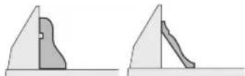
-nerHanHaMaCaTa3aPra3aHe

OcbEN TOBA B 3aBNCMOCT OT IINPOOHATA Ha IPOQHHATA JETBA MOXETe Da H3IbIHRAte Cpe3OBete C HIN 6e3 H3TERJIHe.
BnHaHn H3np6BaIte HAcTpoEHn HaKIOH Ha Cpe3a (xOpH3OHTaIeH N/IIH BepTKaIeH) NpPBO BbPxy OTNaDbUHO TpyN-ue.
Поберки и Настpoиka Ha ochOBHnTe napametpn
3a ocnhypbahe Ha npneu3HH cpeoBe CnED HHTeH3HBHO 3- non3BaHe Tpa6Ba Da npOBepBaTe OCHOBHte npaMeTpHa eNEktpoHnCTpymehTa n pni Heo6xOHMocT da Tn KopnrnapaTe.
3a cetaTtpr6ba da HMaTe OHTN CbOTBeTHITE CNEUAnH3paHn HcTpyMeHTN.
Ta3n DeHocT 6bDe H3BbpHeHa 6bp30 N KaueCTBeHO BOTOpH3npaH cepBn3 3a eEnKToPOnHcTpymeHTn Ha BoI.
HacpoBaHe Ha cTaHdApTeH BeptHKaIeH HAKIOH Ha cpe3a 0^
-Пoctabete eIeKtpOnHcTpymeHTa B I03nua 3a TpaHcnpOpTnpaHe.
-3aBbptTe cteHda (33)doHaIpe3a (14)3a 0^ .IocTbT (12) Tp8Ba Da ce 3axBaHe B KaHana COTyETINBO Ipeu-pakBAHe.
Поверка (вж.фг.R1)
-HactpoIte brrnomep Ha 90^ n ro noctabete Ha Macata (33).
Pamoto Ha TpaHcnpTnp Taep6Ba Da e noPaBHeNo no TaTa cn DblnHa CnpMa UPKyIaRn HnDnck (34).
Perynnpahe(Bx.Фиг.R2)
- Ocb6o6e3aCtoTOpBaauTa pkoXBAtKa (13).
-Pa3BnIeDBAt3aCToOpRBaunBnHTa(54)(Hai-Manko 1obopot) CnYXKnOy(10mm).
-Pa3BnTepeynpaunBAHT(56)npn6n.Ha3o6opota)CseCTOCTeHHNKNIOU(4MM)(30).
-3aBbptetepeynpaaBnHT(55)cWecTOCTEHNNKINHOU(4MM)(30)HAJIBOHNIHADCHO TAKA,ye paMOTHa bIOMepaJa ce NpabHNNo qanata CNDbJKNHaCNPAMO UPKyIpa.
-OTHOBO 3aterheTe 3actonopBaAaTa pBkoxBatka (13). CneToBA 3aterHeTe OTHOBO nbpBO perylnpaunn BHT (56) nCneTOBA perynpaunte BNHTOBe (54).
Ako cnei peryinipaheto ctpeknite (28) n (21) He cbbnadtoHcMapknpoBknte O Ha cKaIaTa (27), pa3BnTe 3acto-nopraaHTe BnHTObe Ha ctpeknTe c o6hKnHOBeHa KpbCTaTa
OTBepTKa HIOpPaBHHeTe CTePJIKeTc CNpRAMo CbOTBeTHaTa MapKINPOBaKoO.
PerynnpaHe Ha BepTKKaIeH cTaIaIapTeH bTbN Ha HAKIOH 45^ (BnBO)
-NoctabeTe eNeKTponHcTpymeHTa Ba pa6oTHa No3nua.
-3aBbptete cTeHda (33)do HAppe3a (14)3a 0^ .IocTbT (12) Tp8Ba da ce 3axBaHe B KaHana COTyETnIBO ppeu-paKBaHe.
-Издрпангдддддддддддддддддддддддддддддддддддддддддддддддддддддддддддддддддддддддддддддддддддддддддддддддддддд徴улрума onopha 7.
-0cb6o6e3actonopBaata pBkoxBtka (13) nHaKNoHETe IIb3raUTo ce pamo, KaTO rDpKHTe 3a pBkoxBatkata (3),doynop HanBo (45).
Поверка (вж.фг. S1)
-HacptpoTe brrnomep Ha 45^ n ro nocTaBeTe Ha Macata (33).
PamotoHa TpaHcnpTnpa Ta e no npBaHeNo no nata Cn DbJHHa cnpmo UPKyIapHHN Dnck (34).
Perynnpahe (Bk. qnr. S2)
-3aBbptetepepynnpaunBHT(57)CseCTOCTEHNNKIOU(8MM)HANBOHNAHADCHOtaKa,YepaMOTHO bILOMEpa da ce IOpbaHNIOJNaTaCNbIKHa cnpaMOuPKyIpa.
- OTHOBO 3aterHete 3actonopraaata pkoXBtka (13).
Ako Cnei HacTPOBHaBeHO CTpeKNKe (28) H (21) He ca nOp-paBHeHc M CapKnPOBkata 45° Ha cKaIaNATA (27), npOBePeTe Oue BeHbX TOUHOCTTa HA CTpeKNKe TpNn HAKnO H O. Cnei TOBa OTHOBO HAcTPOHe HAKnOH HA BepTKaJIHHcpe3 45°
Perynnpahe Ha BepTKaJIeH cTaNdApTeH bTbN Ha HAKIOH 45^ (BDACHO)
-Noctabete enektpoHHCTpyMeHTa Bpa60tha no3nua.
-3aBbptete cTeHda (33)do HAppe3a (14)3a 0°.IocTbT (12) Tp86Ba da ce 3axBaHe B KaHana cOTyETnBO ppeu paKbaHe.
-ИздрпаTeДOKраи habьн ДяСЧаТа рERYИPyema onopHaшиHA(7).
- Ocb6o6e3aCtOnopBa7aTpaBkoXBAtKa (13).
-HaknoheTe nnb3raIOTo ce pamo, kato ro dbpKInTe 3a pbKOXBaTKata (3) IeKo HANBO OT NO3nurTa O' n 3aBbPTe pbKOXBaTKata (32), DOKATO DOCTHHe-Te JEAHN HaKIOH BB BepTnKaJHa paBHnHa.
-HaknoheTe nB3raUTo ce pAmo Do ynp HnAChO (45°), KATO DpKHTe 3a pbkOXBtKaTa (3).
Поверка (вж.фг.T1)
-HacptpoTe bIIOmepe Ha 135° n ro noCTaBeTe Ha Macata (33).
PamToHa TpaHcnpTnpa6BaJa e noPaBHeNo nuaTa Cn DbJHHa CnPMAuPKyIaRPNHnDnck (34).
Perynnpahe(Bk.Фнг.T2)
-3aBbptetepeyHpaunBAHT(58)CweCTOCTeHHN KIOU(8MM)HANBOHnHADCHOtaKa,ye pAMOTHa bILOMEpa da ce IOpabHNIOuNaTaCNbIXKHa CnpAOM UPKyIpa.
- OTHOBO 3aterHete 3actonopraaata pkoXBtka (13).
Ako CnEi HAcTPOBBAHETO CTpeKNITE (28) n (21) He ca nonpaBHeHH C MapKnipOBkata 45^ HA cKaIaTa (27), npOBepeTe Oue BeHbX ToHOCHTA Ha CTpeKNITE npHn KaHIOH O. CneI TOBa OTHOBO HAcTPOJE HAKNOH HA BEpTKaJIHHcpe3 45^
IopapBnBaHe Ha ckanata 3a bTbHa CkocBaHe B xOpH3OHTanHa paBHHa
-Noctabete eeneKtponHcTpymentaBa pa6oTHa no3nua.
-3aBbptete cTeHda (33)doHaIpe3a (14)3a 0^ .IocTbT (12) Tp86Ba da ce 3axBaHe B KaHana COTyETINBO npeuPpaKBaHe.
Поверка (Вж.Фг. U1)
- YctahOBete brrnomep Ha 90 n ro noctabete Mexy onopHata uHa (8) HzpkyIrpHna DNCK (34) Ha cTeHda (33).Pamoto Ha TpaHcnpTnpa Tpr6Ba da e npapBHeNo no ynata Cn DbJHHa cnpMo UpkpyIrpHna DNCK (34).
Perynnpahe(BK.Фг. U2)
-PaBnIteH uYeTnpHtepeYnPaun BnHTa (59)cJeCTOCTeHHN KIOU4 (4 mm) (30) H3aBbPTeTe pa6OTHNnIOT (33) 3aeHNO cbc cKaIATA (31),DOKATO pAMOTO Ha bTlOMepa ce NpDpaBHn CnPMAO UINPKyIaRPNHn DnCK NOIATA CNDbJKNHa.
-OTHOBO 3aTeHHeTBeBHTOBeTe.
Ako cneH hactpoBaHeTo cTePekata (51) He e Ha eHa nn HnHc MapKnpoBkata 0° Ha cKaIATA (31), pa3BnTe BnHTa (60) C o6NknHOBeHa OTBePTka N noDpaBHeTe cTePekata cnPraMo MapKnpoBkata 0°.
HactpoBahe Ha cInata Ha 3aTrahe Ha 3actonopbaata pboKoBAtka (13) (Bx. qnr.V)
CnataHa3aTaraHeHa3actoopBaataPbkoxBatka(13) MoKe da6bdepeynpaHa.
IpoBepka
CnataHa3aTaraHeHa pBkoXbTkata Tpr6BaJa 3aIbPka nIb3raio Ce paMo 3npaBO n CnpyHO npn npOn3BoJe HAKIOH BvB BEpTKaJIHa paBHHa.
Perynpane
- Ocb06o0eTe 3actonopraaata pkoXBtka (13).
-3aHaHamaHte CnIATA Ha 3aDbpKaHe, 3aBpTepepynnpaunBnHT (61) crny KIOU (17 MM) o6paTHo Ha ccoBHNKOBATA CTpeNka, peCn., 3a Da yBeINuHTe CnIATA Ha 3aDbpKaHe, rO 3aBbptete NO YacOBHNKOBATA CTpeNka.
-HaTpoTe HaKIOH BbB BepTKaHa paBHHa, 3aTeHHeTe 3aTOnOpRAaTa pBkoXBaTKa (13) n npOBepe daHn CTe HaCTpOJIIN JKeNaHATA CnHa H3atrahe.
TpaHcnpToPapHe (Bx. qnr.W)
Ipei TpaHcnpTnpaHe Ha eEnKtpOnHcTpymeHTa Tp6Ba da H3nbHnTe CneHnTe CTbKn:
H36ytaIte nIb3raUTo ce pamo (23)doKpaHn3aHro 06e3oNacTe B Ta3n No3uHn(BK.,O6e3oNacBaHe Ha nIb3raUTo ce pamo",cTp.23).
-YBepete ce, ye DbIbOuHHHnT OrpaHnHTen (25) e HATNC-HaDOKpaHnABbTpne n peryInpaunT BnHT (24) BN3a BOTBopa 6e3 daOnnpa DblbOoHHHnO rpaHnHTen npi npemecTBaHe Ha Nb3raUTo ce paMo.
324|Бьлгарский
-Ппекаши рамоToHa ПьзгашоTo ce paMo DoToKOBa
надoly,у.TраснорТоTo obe3oanacBaHe (26)Да ce
пптусяdoКрай Habтpe.
-BkapaTe ydbnKHTenHata ckO6a (16)doKpaHaBbTpe.
-HaTpoTe bBn Ha HAKIOHa BB BepTKKaHa paBHnHa 0^ n 3aTeHHepeKoXBaTkata (13).
-3aBbPtepepaOTHnI (33)doynopHnBaHO 3aterHeTe pkoXBtKaTa(11).
-Bbpxke3aXpaHbauNkabenCneHTata Cbc 3axBaune62).
-OTCTpaHete BCNUKn DeTaNn INPNCIOcO6NeHnR, KOHTo HE MoRaT Da 6bDAt MOHTnpaHn 3dPaBO KbM eNEKTPOHCTpymeHa.
-ПиТраспорТаРе NOВьзмохнocTЯСТаВЯТe HEN3-Non3BaHHTe UINKpyAphNДИСКOBe B 3aTBOpEH KyTNH.
-Hocete eneKTPoHnCTpyMeHTa KaTO rO XBaAte CTpaHnH0 3a OTbOpHTe 3a XBaAaHe (17) BbPxy MacTa Ha cIpKyIpa.
PnTpaHcnpTnpaHeHaeneKTPoHcTpymeHa 3a3axBaAaHe H3NoI3BaHte CaMo IpeBnEHNTe 3a CeNTa enEmTHN, HIKORA ppeJnA3HTE CbOpBXeHn, Nb3raUto ce pamo (23) nnn pbkoXBatkata (3).
PoiDlbpJkaHe n cepBn3
IopdbpxaHe n nouchTahe
Pepn H3BpUbaHe Ha KaKBHTo H Da e DeHocTH No eneKTPoHCTpyMeHa N3KNIOVAIte UenCena O TaxpaHbauata MPeka.
3a da pa6oHTe KaueCTBeHO 6e30nacHO, noDdbpXaIte enEeKtpOHcTpyMeHTa HBeHTHnaUHOHHTe MyOTBOpN uCTH.
Korato e Heo6xOHa 3aMHa Ha 3axpaHbuaa Ka6en, TpRbBa da ce N3BbPn B OTOpN3npaH cepBn3a eNeKTponHCTpyMeHTn Ha Bosch, 3a da ce 3ana3n HnBOTo Ha 6e3onacHOCT Ha Bosch eNEKTPOnHCTpyMeHTa.
UapHnHPO OKaueHNrT ppeNa3eH KOKyX Tp6Ba Da MoKe da ce 3aTbApra CaMOCToTeHNo. 3aTOBa NOpIbPkaJTe 3OHaTa OKONo Hero UHCTa.
BnHaH cnEpa60Ta nouCTBaHTe npaxa H cTbprotHHte C npOyXBaHE CbC rCTeH Bb3dyx Hm C MeKa YETka.
-PeIOBHO noHCTBaIte poKata (20) nIb3raIoTo ce paMo (23).
DonbHnTeHN npncno6neHH
KataJoxeH Homep
BnHToBa cko6a 1 609 B06 203
Bloxk1609B04263
1609B04264
PpaxoyNoBtTeHa Top6a 1 609 B02 595
AanTep 3a npaxoynaBne 2607 001 977
BannHNo 3a cneHnTe TnObe:
3601M2704./...OL./...08./...OB./...OK.
| Каталожен Home | |
| Цркуларни дискове за дырво и пioч, панelli и лет- ВН | 2 608 676 047 |
| Цркуларни дискове за ТБьрда дырBEСнHA, KMПОЗИТ- HN MaTeРнALH, пlaCTMachи NGBETHN MeTAlH | 2 608 640 969 |
| Цркуларни дискове 254 x 25,4 mm, 40 3b6a | 2 608 640 970 |
| Цркуларни дискове 254 x 25,4 mm, 40 3b6a | 2 608 640 971 |
| Цркуларни дискове 254 x 25,4 mm, 40 3b6a | 2 608 640 971 |
| Валдно за сеДнITE тINOBe: 3 601 M27 00./... 03./... 07./... 06. | |
| Цркуларни дискове за дырво и пioч, панelli и лет- ВН | 2 608 642 530 |
| Цркуларни дискове 254 x 30 mm, 40 3b6a | 2 608 642 530 |
| Цркуларни дискове за ТБьрда дырBEСнHA, KMПОЗИТ- HN MaTePнALH, пlaCTMachи NGBETHN MeTAlH | 2 608 642 528 |
| Цркуларни дискове 254 x 30 mm, 80 3b6a | 2 608 642 528 |
KnneTcKa cnx6a H KOHCyNTaun OTHOCHO ynoTe6ata
CepBn3bI tJe OTROBOpH a BbnpocHe Bn OTHOcHPOMeOHn NOpIpbKka H3akyenHn O T Bac npOyKT, KaKTo n OTHOpe3epBn qactn. POKOMNoEHTHN Yeptexn NnHfOpMa-ua 3a pe3epBnHTe qactn Iue OTkpneTe n Ha:
www.bosch-pt.com
EkntnoKohcyIaunOTHOCNoYnOte6ataHaBoschue Bn NOMORHe C yOBONCTBne npn Bbnpocn 3a HauHtene npoDyKTn nTexHNTe akcecoapn.
MOn, npB Bnpocn npnp npOpBaHe Ha pe3epBHN qactH BHHar nncOcbAte 10-undpeHnKaTANOKeH Homep, n3nnCah Ha Tabekata Ha ypea.
Былгаря
Robert Bosch SRL
Service scule electrice
Strada Horia Macelariu Nr. 30-34, sector 1
013937 Bucuresti, Romania
Te.n.: +359(0)700 13667 (Блларскн)
_aKc: + 40212331313
Email: BoschServiceCenterBG@ro.bosch.com
www.bosch-pt.com/bg/bg/
DpyrH cepBn3HH aPecn uE oTKpHeTe Ha:
www.bosch-pt.com/serviceaddresses
Бракуbaнe
C orneon ana3BaHe ha OKoHnHa T cpea eneKtpOnHCTpyMeHbT, DOnbHnHTenHnTe npncnoc6nEHHn O nOakOBkata Tp8-
Ba Da 6bDaT NoDIOKHeH Na NoXOJaA ppepaBcKa 3a NOBTOPOHOIIN3BaHe Ha CbIbPkaUInCe CB TIXCypOBHH.
He n3XbBpIaIe eIeKtpOnHcTpymEnTH npn 6ntobte OTnabu!
Cama 3a cTpaHn ot EC:
Cbflnacno eBponecka DnpeKTHBa 2012/19/EC nXapMOHN3npaHETo Ha HauhoHaHNoTO 3aKHOHaTeNCTBO C He enEeKTPOHH N eneKTPnuecKn ypeDn, KOHTo HE MoTAT Da CE n3non3Bat, Tp8Ba Da 6bDat cb6paHn OTdEnHo n Da 6bDat npedaBAHN 3a OOnl3OTBOPraBaHe Ha CbIbpxAunTe CE B TEx CypOBHH.
PnHnHePaBnHO hXbBpIaHcTapHte eKeTpueckn H eKeTpOHH yPeHN NopaHb B3MOxHOTo HAnuYe HaOnaCHN BeueCTBa MOrat Da OKaKaT BpeHN BnHnHn Bbpx OKoHaTa CpeDa HOpBeWkoTo 3dpaBe.
MaKeDoHcKn
Бe36eДHOCnHaNoMeHn
OnuTn npdynpdyBaHa 3a 6e36eHocT ha eNEKTPnuH aIaTH
PNEy-PENYBAHbE
PpOHTajTe rH cTte 6e36eHocn H pEynpeyBaHa, mNyctpaun H cneuФkaun npnoKeHH co
OBJeKtpuH anat. HenpndpxyBaHeto Do CHTe ynATCTBA pnpIOKeHH NOOly MoKe Da IOBeHe Do cTpyeh yIap, noKap H/INH TeIKN NOBpeH.
3auybaTe r6e36eHNOCHNTpeynpeyBaHa ynaTcBA 3a KopncTebe H3a BO NHHHa.
PnoHOT,eneKtpnue H anat" Bo 6e36eHocnHTe npEnpyeYBaHa ce OndecyBa Ha eNktpnHn anapATn wTO kOpCTaT cpyja (ka6enckn) nAn anapATn wTO KopcTaT 6aTePN (akymnatopcKn).
Ee36eHocT ha pa60THNt npocTop
Pa6oTHNOT pOCTOP OpKByBaJTe Ro UcT H Do6poOCBETnE. IpenoHnn TEmHn IpocToPm MOKe DaDOBeaT Do HepeKa.
He pa6oTe co eNEKTPnHHTe anaTH BO EKCNIO3MBa OKINHa, KAKO Ha npHMeP, BO pncycTBo HA 3anaNNB TeHocTH, rAcOBu Hn npAunHa. ENEKTPnHHTe aIaTH CO3daBaat NCKPN KOHTo MOKe da Ja 3anaanpnaHHata HnH rAcOBHTe.
JpxkTe rH deuata n npncyTHnte noaaneky dokepa6oHTte co eneKtpuehen aat. HeBHMaHHeTo MOKeJa npedn3Bnka da n3ry6nte KOHTpOna.
EneKtpnHa 6e36ednoct
PnPKnyokot Ha eNektpnHnot anat Mopa da odrobapa ha npKnyHncaTa. Hkoraaw He ro
MehyBaTe npKnlyOkoT. He KopnCTHe npKnLnyHn aadTepn co 3a3emjEnHe eEKeTPhHn aalTH. Hen3MeHenTe npKnLyOuHn COoBETHe npepNkyHnU r Ho HamaJyBaat pN3NKOT on CTpyeH ydap.
M36erhyBaJTe TeneCen KOHTaKT co 3a3emjeHn NOBpuHH, KAKo Ha npHMeP, UeBKN, paJaTOpH, MeTANH NaHcN N aDINHHNc. IocToN 3rOJIeMeH pU3NK oD cTpyEh ydap aKO BaWte To TeI e 3a3emJeHO.
He HnH3noxybaJte eneKtpnHnte anaTHa doxk nnBnaXnn yCNOBn.AKO Bne3e BOa BO eneKtpnHnot aIaT,Ke ce 3rOlenmuN KOCTpyehyap.
He noctanybajte hecooBetheo ka6enot. HnKoraw He ro KopnCTeTe Ka6enot 3a Hocebe, Bneuehe nn NcknyBahe oCtpyja Ha eneKtpnHOT anat. Ka6enot yybaJte Ro nOaneky od oran, MaCno, ocTpN HBnH Nn NOBxHN DeOBH. OWTeHTn Hn 3aIJIeTKaHn Ka6nro 3rOJeMyBaat pN3NKOT oCtpyeh ynap.
Pn pa6oTa co enektpueH anat ha OTBopeHo, KopncTepe npdoonxeh Ka6en COOBETe 3a HADBOEwHa ynotpe6a. KopncTebeTo Ha Ka6en COOBTeEH 3a HADBOEwHa ynotpe6a ro HamanyBa pNIKOT OCTpyeH yap.
AkoMopa da pa6oHTe co eJektpueh anat Ha BnaXho MeTo, KopHeTe 3aWHTHe ype3a dHpepeHnJaHa cTpyja (RCD). KopHeTeHo HA RCD ro HamaNyBa pN3IKOT od CTpyeH yap.
JIuHa 6e36ednocT
BnTe BnMaTeHn, BnMaBaJte Kako pa6oTne H pa6oTe pa3ymHo co eKeTpueH anat. He KopHeTe eKeKtpueH anat aKe cTe yMOpHn nn noj DejeCTBO Ha dporn, Ankoxon nn neKOBn. EeH MOMENT Ha HeBnMaHne DoJeKa pa6oTne Co eKeTpueHne anat MoKe Da doBeDe Do cepno3Ha nHa Nobpea.
Kopntete NnHa 3aHTHb Onpema.Cekoraw Hocete 3aHTTA 3oN.3aHTTHaTOnPema,Kako Ha np., Macka 3a npaaHHa,6e36eHOCHNyBnKoHTo He ce nn3raat,wnm 3aHTTA 3ayu, konuTO CE KOpCTAT 3a COOdBETH yCNOB,Ne DOBeaTdo HamaNyBaHe Ha nHHIOBpei.
Cnpeute HeHamepho AKTHBnpahe. IpOBepete daHn npekHyBaOT e Ncknyeh nped Da ro BKnyHTe BO ctpya H/nn Co CETOT Ha 6aTeHN, nped Da ro 3emTe Hn HOCTe anatot. HocHe Ha enktpnuHnte aIaNt co npctOT No3nOHHpAH Na pekHyBaOT Hn BklyuBaBe BO ctpya Ha enktpnuHnte aIaNt HJWTO npekHyBaOT e BKnyeh, MOKe da npedn3Bnka Hecpeka.
OTcpanheKaKOB 6nno Knyu 3a perynpahe Hnn φpaunyckn Kny nped da ro BknyuHte eneKtpnuHnot anat. Paunyckn Knyu nn Knyu npkaueh 3a potnpaKnOt DeI Ha eNeKtpnuHNO t aI MaKe Da doBeDe Do nUHa nobpeJa.
He nnpueekopybaje orpanhybaaba. Noctojan Odpkybaje cooDBetna noo6ha npamhotexa. Oba OBO3MOxyBa IIO6pa KOHTpOHa eNEKTPnHnOT anat BO HENpeBnINBnCITyaun.
06NeueTe ce cooDBetHO. He Hocete uHPOka 6nEka n HAKHT. Kocata n anHtata Tpe6a da 6ndat noJanaeky Od NOBHXHNTe DeNoBH. UHPOKATA 6nEka, HAKHTOT INN DOnrata KOca MoKeJa ce 3aKaayat 3a NOBHXHNTe DeNoBH.
AkoceKOpHCTaTIOBp3AnHypeHn3aBaDeIbe npauHnHaCobupaBeIpeDMeTH,IpOBepTeDanCe npabHNOBp3AnH KopHeTo npauHaMOKe Da HnHaMaHnOnaCHocHTe IpeH3BnKaHOnd Hea.
He do3BonyBaJte HcKcyTBoTo cTeKHato co yecta ynoIpe6a Ha anatne Da Be HanpaBn CnokojHn da rHrHnOpnpate 6e36ednOCHnte npHHncnHpHn HBBHOTOKopncTebe. HeBHmAtenHO DnKxBe MoKe da npEni3BnKa cepno3Ha NobpeDa BO den Od cekyHda.
yntpe6a H yBaHe Ha eNktpnHne anat
He ro npeontOBapyBajte eneKtpnHnot anat. KophCTete cooDBetEn eKeTpyen anat 3a HameHata. Co cooDBETNt eKeTpyen anat noD6po, no6e36edno n no6p30 Ke ja h3BpuWite paOtaTa 3a Koja e HameHet.
He Kopnctete enektpueh anat ako He moke Ta BO BKnyuHTe H NCKnyuHTe CO NOMOu HA npeKNHyBaOT. Ceko jeneKtpueh anat kojsto He moxe da ce KOHTpOInpa co npeKNHyBaOT e onaceH Mopa da ce nonpaBN.
NcknyeTe ro enektpnHnot anat od ctpya n/nnn H3BaJeTe ro ceTt ha 6aTePN, aKO ce BaHn, nped da npaBHe HeKaBn pnpnafoyBaHa, MeHyBaTe DononHntHa onpema nnro cknadnPate enektpnHnot anat. Co OBne npeBeHTNBHn 6e6eHocnM mepKn ce HaMaanyBa pn3IKOT od cnuyajHO BKlyuYBaBe Ha enektpnHnot anat.
Yybajte rH eneKtpnHHTe anaTH noaneky od doqat Ha deua H He DO3BonyBaJte nucata KOHpe pakybane co e neKtpnHnot anat HHe Ce 3aNo3Haehn Co Oba ynatCTBO da pa6oTat co hcthot. EneKtpnHnte anaTn ce onacn BO paqete Ha heo6yuHn KopncnHn.
OpjyBaBe Ha eNekTpHn H aIaTH NdoONHtEnHa onpema. PpOBepTe ro npamHyBaBeTo HnnpucBpCTyBaBe Ha NOdBHXHHe DeIOBN, CnoJOT Ha DenOBHe H cHTe DpyrY yCNOB WTO MOKe HeraTHBHO Da BnJaat BP3 dyHKUHOHPaBeTo Ha eNekTpHnHOT anat. Ako e OwTeH, OdHeceTe ro eNekTpHnHOT anat Ha nonpaBkA ppeDa rO KopcHte.Mhory HecepKe n ce IpeDnBnKaHn 3apadn HecooDbETHO oDpXyBaBe Ha eNekTpHnHte anATn.
OCTpeH uHCTeTe Hn aHaTHe 3a ceYeBe. CooDBetHO ODPKxyBaHHTe HbUIn Ha aHaTHe 3a ceYeBe NOMaIKy Ce BNTKaat n NOECHO CE KOHTpOINpaAT.
EneKtpnHnO anat, dononHnTeHnata onpema, denOBte Hdp., KopnCTe Tn BO cornaHcOCT co Oba ynatCTBO, BHmAbajte Ha paobHTte ycNOBn paBOTATA koja ja BpuNTe. KopnCTeHeto ha eNEKTPnHnO anat 3a npTuHaMeHH MoKe Ja DoOBeDo ONaCHN CInTuauu.
PaKHTe H NOBpHHHTe 3a DpKHe ODPxByaJte rN cyBN, NCHTH HEN3MaCTEH. PaKHTe H NOBpHHHTe 3a DpKHe ITO CE IIN3raat HE OBO3MOxByaAT 6e36eHNO paKyBaHe H KOHTP0la Ha anatOT BO HnpeBnIINBn CNTyaunn.
CepBncpaIbe
EneKtpnHnot anat cepBncpajte ro kaj KBaHnΦkyBaHO Nue Koe KOpCTN cAmo HdeTHNuH pe3epBHN DeOBn. Co Oba ce OBO3MOxyBa 6e36eHOn odpxyBaHe Ha eneKtpnHnot aanT.
Be36eHocn npedynpeyBaBa 3a aorHn nnn
AronHnTe nnnCe HameHeTH 3a CeYeBe npBO nnn cnHnnpoH3BoHn, He MoXe Da ce yNtpe6yBaAT co a6pa3HBnHnDCKOBn 3a CeYeBe Ha o6oEHn MeTAn, KaKo Ha np. WnKN, npauch, wajKn Hp. A6pa3NBHaTa npaunHa npedn3BnkyBa 6NoKpahe Ha potpaKHTe DeOBn, KaKo ITo e DOnHnOT WtHTNHk. NcKpHTe OJ a6pa3NBHO CeYeBe ro ropat DoHNOT WtHTNHK, 3aceKOT nINaCTNUHrTe DeOBn.
Kophtete cteraun 3a dpkehe ha denot wto ce o6pa6byba kora nocton moxhoct. Ako ro notnnpate denot wto ce op6pa6byba co paka, pakata noctojaHO mopa da 6nde ha ondaneuehoct od hajmanky 100 mm od DBete ctpan HA CEHNOO OD NHATA. He ja Kophtete OBaa NHna 3a CEHe H MHOrY MAHN npuHbA WTO He MOKe 6e36eHNo Da ce 3auBpCTAT HN da ce dpxat co paka. Ako paKaTa ja cTabHTe npeMHOry 6nCKy Do CEHNO To HINlata, NOCTOn rOJIema ONaCHOCT OJ NOBpeDa aKO rO donipTe CEHNOTo.
Denot wto ce 6pa6oTyBa Mopa da 6nne ctaTnueH npuBpCTeH, nn da ce dpxN 3a rpanuHKnOT n 3a macata. He ro ctabaje denot wto ce 6pa6oTyBa BO ceunnoTo Hnn Xne60t co Cno6oHa paka. Cno6oHnn Hn HnpuBpCTeH den wto ce 6pa6oTyBa Moxe da ce otcpnn co rOema 6p3nHa n da npedn3bna NOpeDa.
PnHTncheTe ja nnata Hn3 denot wto ce 6pa6oTyBa. He ja Bnueye nnata Hn3 denot wto ce 6pa6oTyBa. 3a da npeceye, noHnreTe ja rnaBata ha nnata na Nobnueye ja npeky denot wto ce 6pa6oTyBa 6e3 ceeybe, BKnyte re MOTOPOT, PnHTncheTe ja rnaBata Ha nnata HADONY Tpyhete ja nnata HN3 denot.Co NOBNEkyBaHe Ha nnata DoNeKa cyeTe CEHNOTO MOKe Da ce NCKaun Ha BPOT Ha denot wto ce 6pa6oTyBa H CnHO da ro OTpnn CKlONOT HA CEHNOTO KOH onepaTOPOT.
He n npekpcytbajte pautee Bp3 odpehata nnHjia 3a cehe nped n 3a9ceHnOto Ha nnHATA. Dpkehe Ha denot to ce o6pa8oYBa co BKPCTeHN paue t.e. DpKehe Ha denot Ha deChata cTpaHa oD ceHnOto Ha nnHATA co neBa paka HnObpaTHo eMHORY onaCHO.
He nocerhybajte 3a rgpauHnHkOT ha pactoJAHne nomano od 100 mm od DBete ctpaHn Ha ceHHnTo 3a da rH oTcpaHNTe DpBeHHTe ocTaOn Hnn 3apdH npuHa DoKe Ka CEHHo To pOtna. Moke da He 3abeneKHTe konky 6ncky eceHHTo DO BaWata paka n Mooke cepno3HO da Ce NobpeHnte.
Pa3rneajre ro denot wto ce 6pb6oTyBa nped da 3anouheTe co ceehe. Ako denot wto ce 6pb6oTyBa e HAKPBENHn HABaHEn, npuBpCTe ja HADBopeHHATA HABaneHa CTpaHa Ha rpaHHNKOT. Cekoraaw npOBepyBajte dAnn HMa npa3HHa Mef y Denot wto ce 6pb6oTyBa, rpaHHNKOT n Macata NOKpajnnHjata Ha ceeHe. HAKPBENHn HABaJIen DeI wTo ce 6pb6oTyBa MOKe Da CE H3BHTKa HIn NOMEcTH N da npEIN3BnKA BHTKaHe Ha CEHNTO KOe pOTnpa npn CeueHe. He Cmee Da HMa WajKn HIn Dpyr HADBopeHHn NpeMETH BO DENOT wTo ce 6pb6oTyBa.
He ja yonptpebyaje nnaata ako ha macata,ocben denot wto ce o6pa6oTyBa, hma anaTH,dpbeHH ocTaTOUH dp. Mano octatou HnI paccpnaHn npuHa dpBO Hn Dpytn PpeDmetn aKO ce Donpat Do poTnpauKOTcceHNO moke da ce pacpPnat co TOnema 6p3nHa.
Ceye camo een den nctobpeHno. NobeKe npuHa He MOKE COoBETHO da ce 3aUbPCTAT INI NOBp3AT MOKE da CE qatAT 3a CEHNOTIO INI da CE H3MeCTAT BO TEKOT HA CEeHeTo.
PpOBepTe daHn nnata 3a ceeheNoar o eMOHTnpaHa HnH HameCTeHa Ha paMaHa, Ubpcta pa6oTHa NOBpHHa nped Ja ja KopHcTHe. PAmHa nUbpcTa pa6oTHa NOBpHHa ro HamaNyBa pN3KOT nnIaTa 3aceHe neoar da CTAHe HeCTabHnHa.
Mcnnnapjeta pa6oTata.Kora ke ja npomeHte KocnHATA HIN NOceEHOT aOR HA 3aKocyBaBe, npOBepete daHrpanuHnHKOT KOJ ce NOdecyBa e npABnHNO nOCTaEBH 3a DpXeHe Ha denot wTO CE 6pa60TyBA HekA HeMa Da rnoNpueyBa CeHNOT HN 3aHTTHNtCNCTEM. Be3 BknyuBaHe Ha anATo HA ON" H63 JeNTo WTO ce 6pa60TyBa Ha Macata, DnHexTe Ro ceHnIto HA HnIaTa Hn3 ueNoCHO CmMyInpaH npecek 3a Da pOBepTe DaHH Ma HeKaKnPipeKN Hn OnacHOCT Da CE pceYe rpanuHKnOT.
06e36eTe cooBteH notnnpa, kako Ha np. 1doataK Ha Macata,HorapKn 3a Notnpa Ha nHa Ta Hdp.,3a den wTo ce o6pa6otyBa koj e nouPOK nn noOnrO od ropHnot den Ha macata.AKO deNoBHTe wTO ce o6pa6otyBaat ce noonrn Hnn noWnPOKn Ond nHaTa 3a ceuehe noar oan moKe da ce Habanat DOkONky He ce 3aucbpcHe. Ako OTcehen den nn den wTo ce 6pa6otyBa ce Habain, MoKe da ro noDnHre DOnHnOT WTHTNK nN da 6nde OtfpneHo OD potnpaKOTO ceynno.
He Kopnctete npyro nueke kako 3aMeHa 3a odoatok Ha Macata nn KAKO dOnonHntenepkau. Hecta6nneh dpkaay 3a denot wto ce o6pa60TyBa MoKe da npedn3bKa 3aopaKahe Ha CEHNO To Hn NOMeCTyBaBe Ha denot wto ce o6pa60TyBa BO TEKOT HA CEeHbeto N Da Be NOBneye Bac N NOMOHNKOT KOH potpauKOTO cHIno.
OTceueH den He cmee da ce 3aRnabn Hnn npntncka KOH potnpauKOTcEHHNO.AKe oOrpaHnueHO, t.e. CO NOMOHa RaPAnuHnUte 3a DoJXnHa, HnceEHNOT dEe MoKe Da ce 3aRaNB Ha CEHNOT nCINHO da Ce OTpPNi.
IocjoaHO KopHCTeTe cTera Hn npuBpcTyBaH npabHHo DN3ajHnpaH 3a DpxKeHe Ha TpKaaneH
MaTePnJan,KaKaHa np.,pNaChN HnueBKn.IpaKHTe CECKHOH KOH BPTeHe OdoKea Ce CeyAT N npEIN3BnkyBaat CeuNTo Da rO 3aceKyBa n Bneue denOT CO BaWata paka KOH CEuNlOto.
Octabete ceeynoTo da Docthne cenocha 6p3nHa nped a ro donpe denot wto ce o6pa6otyBa. Co oba Ke ce HamaJIIN PN3NKOT Denot wTO ce o6pa6otyBa da 6nde otppneH.
Ako denot wto ce o6pa6oTyBa nnH ceHHnTo ce 3aIaNbH, ncknyute ja aorHata nnHa. Nouekajte cHTe NOdBHXHN DeOBN da 3actaHAT H NCKnyute ro npNKlyyOKOT on CTpya H/nnn H3BaTe ro nakyBaBeTo co 6atepn. Iotoa H3BaTe ro 3aIaNabeHOT Maepnjan.AKO npOdoJnkte da ceyeTe CO 3aIaNBeH den wto ce o6pa6oTyBa moKe da H3ry6nTe KOHTpONa Hn Da ja OWTeTne NNlata.
OTkakoKe 3aBpuHTe coceheTo,ocno6oTe ro Konqueto,dpKte ja rnaBata Ha nHaTata HADony N noueKaJte ceuHnOTo da 3actane He nped da Ro h3BaHTe HceuHnOt Den. Pn6bNkyBaHe Ha paKaTa do ceuHIO KOe ce yUHTe BpTH e onaCHO.
Држete ja paqukataцbpcto kora npabnte hecenocen 3acek nnn KORA ro ocnobodybaTe konyeto nped nnilata da 6nnde ctabea BO ceNocha haonha no3nju. CoNpaHeto Ha nnilata moKe da npedn3Bvka rnaBaTa Ha nnilata HehanejHO da 6nnde nobLeueHa haoNy Ida npedn3BvKa onaCHOCT ninn NobpeJa.
He otnywajte ja paqukata ako rnaBATA ha nnilata ja Hma doctnHato hajdonHata no3nju. CekoraW bpaKaJte ja paHNO rnaBATA HA nnilata do HajropHaT a no3njuJa.AKO rnaBATA Ha nnilaTa ce DnKn HEKOHTPOINpHo, Toa MoKe da DOBee Do PN3NK OJ NOBpeN.
Opjybaje ja nctotaHa pa60hTo MecTo. MeaBnHte Ha MaTepnaJInc ce ocObeHo onaChn. IpaTa oNcehen metan moKe da ce 3anaHn EKcnIOnpa.
He KopncTeTe TAn, NyKHaTH, CBNTKaHn Hnn OoTeteHn HCTOBn 3a Nnna. IInCTOBnTE Ha Nnata Co TAnn Hn HnnpaBnHH 3anu, 3apaH npeTeCHNt pe3en npouen, npedn3BnkyBaat 3rOleMeHo TpneBe H 3arNaByBaHe Ha NcTOT Ha Nnata Hn NobpaTeH ydap.
He Kopnctete NtCTOBN 3a Nnna OJ BnCOKO nErnpan 6p3ope3eH yenK (HSS-ynNK). TaKbnte NtCTOBN Ha nnla MoKe IecHO da ce cKPwaT.
CekorawkopcteteceunnacoTouhaRonemnHa Hopma(HjaamHTCKNHaonpoTHPKane3H)3aap60 npKn.CeunKaONHeOJROBapaATHaMetAHNOTen3a MOHTpaBeHaCeuNtOKeH3ne3aODcpeHHTeTo,TO Ke npEn3BnKaγ6BeHe HA KOHTpOla.
Hnkoraaw He rnoctpahybajte octatounte od ceueheTo,dpBeHnTe cTpyroTHn H cn. od noneto 3a ceuehe,doekae Bknye h enektpnuHHOType.
Hajnpbo CTabe ja paqkata Ha anapato Bo no3njuHa Mnpybahe nnoToa Ncknyute ro eNeKtpuHnot anapat.
He ro fakajte nctot od nna tno pa6oTata,dokeka He ce onaH. NCTOT 3a nnata 3a BpeMe Ha pa6oTata ce BKeU TyBa.
O3HaKn
CneHnTe 03hakCe OJ roIeMo 3haueHe 3a KopncTeheTo Ha BaWnOT eNEKtpuyeH anat. Be MoIInme 3anaMetTe rO 03HaKnTe HNBHO To 3haueHe. BcTHNcKaTa HHTepnpetaJa Ha 03hakHe Bn NOMara NOD6po H nObe36eHDo Da Ro KOpNCtNe eNEKtpuHnOT anat.
O3nHn HNBHO 3HaYeBe
He nocerhybajte co dnaHknte BO noneto Ha ceuehe,doNeKa pa6oTne eneKtpnHnoT anat. Dokonky dojnde Bo KOHTAK Co CEuHNoTO 3a NIIa NOCTOn ONaCHOCT OI NOBpEDA.
Hocete macka 3a 3auTHTa oJ npab.
Hocete3aWTHTN04nna.

Hocete 3auntha 3a cnyxot. NIOXKeHOCTa Ha 6yUaBa MoKe Da BnJae Ha rSyBeHeTo HA cnYxOT.
Onacha 30Ha! DpKTe rN dIaHKeTte, npCTHe Hn paTe KOkky e MOxHo nOdaNeKy od Oba 30Ha.
He rctabajte npctnte nomery noDBHXHNTe denOBn Ha nI3raKata paKa. MoKe da rN 3aRnABHTe npCTnte I da ce nobpeHTE.
3601M2704.
3601M27OL.
3601M2708.
3601M27OB.
3601M27OK.
0254mm 0254mm
3601M2700.
3601M2703.
3601M2706.
3601M2707.
8254mm 830mm
BHMabajTe Ha dmMeH3nIte Ha ceHnOTo 3a nHa. DnJaMetapot Ha OTbOpOT Mopa ToHo Da 6nDe HAmecteH Ha BpeTeHOTo Ha anatOT. OdkOny e HeonxOAnHO KOpNCTeHe Ha peDyUphn DeOBu, BHIMaBJTe dmEH3nITe Ha peDyUphnOT DeJa oTobapaat Ha deBeHHata Ha ceHnOTo 3a CeYeHe Ha nnJaMetapot Ha OTbOpOT Ha ceHnOTo 3a nHa, KaKo H Ha nnJaMetapot Ha BpeTeHOTo Ha anatOT. DOKONy e MoXHo, CO ceHnOTo 3a nHa KopNCTeTe rN hCnpaAHte peDyUphn DeOBu. DnJaMetapot Ha CEHNOTo 3a nHa
03NaKIMHBHO3Hauebe
Mopa Da OJROBapa Ha noJaToUte Ha 03HaKaTa.
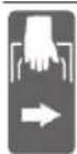
Ipn TpaHcnpTdpxete ro eneKTPnHNOt ypeN CaMO Ha OBHe O3HaueHN MeCTa (XJIe6OBN 3a npKehe).

HnKoraaw He ro HocTe eNEKtpnHnO t anapat 3a DpWkata Ha JIN3raqKaTa paKa.

PnBepTKaHn arHa 3aKocyBaHe MOPA NEBNO TND. DECHNOT
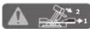
IpoDOnJKeTOK Ha IpaHnHa BODnKa Da ce IpeMeCTN Hn CuNoCHO Da CE OTCTpAHn.
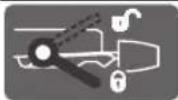
3aTeRhyBaKnot NoCTe OToBopeH: MoKe Da NocTaBHe BepTKKaHn arnn Ha 3aKocyBaBe.
3aTeHyBaKnotIocTe 3aTBopeH: Ke ce 3aDpKn NoCTaBeHNOT BePTKaJEn aRoi Ha 3akocyBaHe Ha IIN3raQkata paKa.
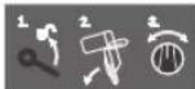
I npkaKyBa NoeDnHeHnTe YekOpn 3a NoCTaBA Ha BepTKaJIHnOT aOrn Ha 3aKocyBaBe.
- OTnywTeTe ro 3aterHyBaKnOT nOCT
- Manky Habanete ja IIN3raKkata paKa KOH IeBO
- Nocabete ro cakaHnot oncer Ha aRONOT HA 3aKOCyBaHe Ha BPTINBOTO KOnHe
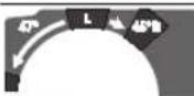
IIOCTaBeTe Ro BepTnKaJIHHOT ONCe Ha aRoiOT Ha 3aKocyBaHbE Ha BPTINBOTO KONue:

HabanyBaHe Ha ceHHIOTo 3a nHa KOH neBO (45^ do 0^ )

HabanyBaBe Ha ceuNTo 3a Nnna KOH decho (0^ do 45^)
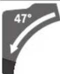
BkyneH oncer Ha HabaLyBaHe Ha IHHraKaTa paKa (-47^ do +47^)

3a nodecyBaHe Ha cakAHOT xOpH3oHTaIe H aOrn Ha 3aKocyBaHe macata 3a NnHa Mopa da 6nne Cno6oNo NOBnKHa, OHN. Da ce 6nOKnpa Cno6oHnO Tk Ha aorONOT
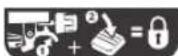
-NoBneueTe ro NoCTOT 1N HcTOBpeMeHO pHTNCHeTe Ro
O3hakn HHBHO 3Hauehebe
KoNueTo 3a CnoBodHnOT TeK Ha aOrIoT Hanapei HaOny
Onnc Ha npoH3B0DoT nepopmaHCnTe

IpoHTaTe rH cHte 6e36eHocn HAnOMeHN ynatCTBa. IpeKHTe HactaHaTu KaKe pe3yNTaT OD HePnPdRpKByBaBe Do 6e36eHOCHTe HANOMeHN yNATCTBA MOKe Da npEIN3BnKaAeNEKTPuH eYap, NoXap N/HH TeWK NOBPeiN.
BHHMaBaJTe Ha cIHKnTe BO npeHnO T dEHa yNaTcBTo 3a KopHe.
YnoTepe6a co cooDbetHa HameHa
EnektpnuyHnot anapate HamaHet 3a npabeHbe Ha donxHcKn Hnnapeunpe3OBn Ha CBpcta noIora co npab pe3 Bo dpBO, KaKo fHKceH ype. PnHToA ce BO3MOXHN XOpH3OHTaHn arHn Ha 3akocyBaHe oD-52°do +60°kako H BepTKaHn arHn Ha 3akocyBaHe oD 47° (Ha neBata cTpaHa) Do 47° (Ha deChata cTpHa).
KanaHTeTHa eNkTPnHnT aIaTe npeBnDnE 3a ceeHe Ha TBPNO mKeO npBO, KaKO nBepKn nLecOHn. Co KopncTeHe Ha cooDBetn Ceynna 3a nnla, moxHO e n ceHe Ha anyMmHymckn npOphnn nPiactka.
HnyctpaqnaHa KOMnOHeHTN
HymepnpaheTo Ha cInKHTe CO KOMnoHeHTe ce OndecyBa Ha npika30 Ha eIeKTPNHOT anat Ha rpaFNUkata CtpaHnua.
(1) Keca 3a npab
(2) 3aTeRrHyBaUKNIOCTHaIIN3raUKNOTMExAHN3Am
(3) Dpswka
(4) Bnokada npn BknyBaHe Ha npeKHyBaOT 3a BknyBaBe/ncKyUyBaHe
(5) 3aunnten Kanak
(6) OcunnaTopeH 3aHTHeKanak
(7) IoecnBa rpaHnHa BOHNka
(8)
(9) Nnoua 3a BMeTHyBaHe
(10) Konque 3a cno6oDen TK Ha aronot
(11) Konue 3aФиксраhe Ha caKaHNot aroN Ha 3akocyBaHe (xOpn3oHTaHo
(12) Ioc3a npTeXoJHO NOCTaBYBaHbHe Ha arONOT Ha 3akocyBaBe (xOpN3OHTaHo)
(13) 3aterhyBaqupaKa3a cakAHnotarOHa 3akocyBaHe (BepTKKaHNO)
(14) KJne6OBn 3a CTAHdApDeH arOHa 3aKocyBaHe (xopn3oHTaH0)
(15) OToBOpHa MoHTaKa
(16) PpOdoJKeH npKaU
(17) XJIe6oBn 3aДрxeHbe
(18) 3aTeRhyBaKnIOCTHa npOdoJKNHnO TpKaA
(19) CToIapcKa cTera
(20) IIN3raUKN BaJIaK
(21) Arnomep 3a Decnnot oncer Ha a ronot Ha 3akocyBaHe (0^ do 47^) (BepTKaHNO
(22) Odmbau Ha ctpyrotHH
(23) IINrataqka paqka
(24) 3aBPTKa 3a noDecyBaHe Ha rpaHnUHnKoT 3a Dna6OuHa
(25) RaHnHnK 3a nnab6ouHHa
(26) TpaHcnOpTeH OcNrypyBaY
(27) CkaIa 3a aroIoT Ha 3aKocyBaHbe (BepTKKaIHO)
(28) Arnomep 3a neBnot oncert Ha aorot Ha 3akocyBahe (47^0^) (BepTKKaHNO
(29) Konue 3a noDecyBaBe 3a 22,5°-aron Ha 3akocyBaBe (BepTnKaJIeH)
(30) Knyu co BhatpewHa WectarOnHa rnaBa (6 mm/4 mm)
(31) Cka 3a arolnt Ha 3akocyBahe (xopn3oHTaHo
(32) BpTnIBo KOnue 3a noDecyBaHe Ha oncerot Ha aronot Ha 3akocyBaHe (BepTKaHoo)
(33) Maca 3a ceuehe
(34) Ceynno 3a nna
(35) AanTep 3a BwmykyBaHe
(36) NcφpyBaHаCTpyrotHH
(37) 3aBpTKa 3a 6nOKnpaHe Ha NoCTHNOmexHaHn3Am HA OcunNaTOpHNOT 3aWHTEN KaNAK
(38) IocTeH MExaHn3aM 3a OCuHaTOpHnO T3aHTHTeH KaNaK
(39) PpeHa 3aBpTKa 3a npuBpCTyaBahe (nokpNBHa nnoa/ocunatopeh 3aunTteH Kanak)
(40) 3aHa 3aBPTKa 3a npuBpctyBaHe (nokpHbna nloa/ocunatopeh 3auTHTen KaNAk)
(41) 3aWTHHa nloya
(42) Bnokada 3a BpeTeHTo
(43) 3aBpTKa co BHaTpeWHa WecTaOrHnHa rIaBa 3a npNcBpCTyBaBe Ha CeuHNoTo 3a Nnla
(44) CTe3Ha npnpa6Hnua
(45) Bhatpeuha cTe3Ha nppa6Hnua
(46) 3aBPTKa 3a 6nokaHa Ha nOeCnBaTa rpaHnHa BOINka
(47) PnpduyBaay
(48) 3aBpTK 3a noDcCyBaHe Ha npHyuYBaHbeto
(49) OTBOPH a cTOnapckata cTera
(50) HaboJha npaupaKa
(51) ArIOMep 3a aroJOnT Ha 3aKocyBaHBe (xopnOHTaHbO
(52) PpeknHyBaay3aBknyyBahe/ncknyyBaHe
(53) 3aBpTK 3a nnooata 3a BMETHyBaHe
330|MaKeDoHcKn
(54)/ 3aBPTka 3a noDecyBaBe Ha OCHOBHaTnOCTaBA
(55)/ 0^ (BepTNkaneH aroHa 3aKocyBaHe)
(56)
(57) 3aBPTka 3a noDecyBaHBe Ha OCHOBHATA NOCTaBA Ka 45° (neB BepTnKaen H aroHa 3aKocyBaHbE)
(58) 3aBPTka 3a noDecyBaHBe Ha OCHOBHaTnOCTaBAk 45^ (deceH BepTKaen H aron Ha 3akocyBahe)
(59) 3aBPTka 3a noDecyBaHb Ha cKaIaTa 3a aroIoT Ha 3aKocCyBaHe (XOpH3OHTaHb)
(60) 3aBPTka 3a noka3aTeNoT Ha aIIN (xOpH3oHTanHO)
(61) 3aBPTka 3a noDecyBaHBe Ha CnIata Ha 3aTeHyBaHBe Ha 3aTeHyBaKNOT IocT 3a CaKaHNOr AnHa 3akocyBaHe (BepTnKaIHO)
(62) 莫菲涅Baeta
Texnukn noaToun
| Плaja 3a onplata GCM 10 GDJ GCM 10 GDJ | ||
| Б Proj ha deten | 3601 M27 04. 3601 M27 0L. 3601 M27 08. 3601 M27 0B. 3601 M27 0K. | |
| HOMINAHа jaunha W 2000 2000 | ||
| Б Proj ha вретжи-bo пазен od min | -1 | 5000 5000 |
| Ораничување настпата стура ● | ||
| Текина согласно EPTA-Procedure 01:2014 kg 31,6 31,6 | ||
| Класа на заштITA | ☐/II /II ☑ | |
| Димензни за coodbetнс сецima за плaja | ||
| Диеметар на сецноу за плaja mm 254 254 | ||
| Дебенина на сецноу за плaja mm 1,7-2,6 1,7-2,6 | ||
| Мakс.ширINA на сеценье мm 3,2 3,2 | ||
| Диеметар на OTворот мm 25,4 | 30 | |
IpaTte Baxat 3a HOMHAnen HanoH [U] od 230 V. Obne npatoOn MoKe da otctanyBaat npn pa3nHn HanoH, BO 3aBnCHoc T od H3Be6bTa BO ODHcHata 3emja.
O3B0EHN HIMHeH3HH HaJeIOT WTO CE o6pa6otyBa (MaKcHMaJIHO/MNHMaJIHO): (BND,IO3BOeHN DmMeH3HH HaJeIOT WTO CE o6pa6otyBa", CtpaHnua 336)
HnΦopMaunja3a6yUaba
BpeHocHTe 3a emncja Ha 6yuaBa ce oDpeyBaat cornaCHO EN 62841-3-9.
HnBtO Ha 3ByK Ha eIeKtpnHnOt anaT oueHeTo co A TnHnUHO n3HecyBa: HnBO Ha 3ByeH npTHcOK 93 dB(A); HnBO Ha 3ByHa jaUnHa 106 dB(A). HeCnrypHocr K = 3 dB.
Hocete3aunhta3acnyxot!
BpeHocTa ha emcnjHa 6uyaba Habeena BO OBne ynATCTBa e N3MepeHa co HopmnpaHa nOCTa Ka 3a MepeBe mOKe da CE KOpNCTa Ma Myce6bHa cNope6bHa enEeKTPuHN anTn. IcTo Taka MoKe Da ce pinnarOu 3a npedBpemeHa npoCeHa ha emcnjata Ha 6uyaba.
Habeenehata BpeHnOCT Ha emncjha 6yaba ce odncycba HA OCHOBHATA npimHeHa H eneKtpnHnot anat. DOKOLky eektpnHnot anat ce KopnCTHa dpyn npimeHH, aIaTOT tTO CE BMETHyBa OTCTanyBa OD HopmTE Nn HeDobONHO ce oPxyBa, BpeHocTa Ha emcnjata Ha 6yaba MoKeJa OTCTanyBa. Oba moke 3NaHTenHO da ja 3rolemn Emncjata Ha 6yaba BO ueNoKynHnot nepnoH ha paBoTebe.
3a npueuHNO OOpDyBaHe Ha emncjata Ha 6uyaba, Tpe6a Da ce 3Me npeBnepnooT BO koj ypeoTe NcknyeH INI eBAJ paOToN, a HE BO MOMENTOT KORA e BO ynotpe6a.
Oba MoKe 3NaHTeHn Da ja HaMaJIi EmHCJata Ha 6yUaBA Bo 9eNoKyIHHOT NepHO Ha paOBeHe.
MoHTaxa
136erHyBaJTe HeBHHMaTeHbKbNyBaHae HeneKTPnHnO anat.3a BpeMe Ha MoTakata H npn CHTe HHTepBeHcHn Ha eKTPnHnO anat,CTpyjHnO npNKlyoK He cMee da ce npNKnyBa Ha HanojyBaHe Ha ctpya.
06em Ha Hcnpopaka
BHHMabajte Ha npnkaot Ha o6emot Ha nCnpaayHte Maepjann Ha noqetokOT od ynatCTbOto 3a ynotpe6a.
Ppe npbata ynotpe6a Ha eneKtpnHnO anaT, daH nCte DONY HabeDenH DenOBn Ce HcnpaHn:
-Пиа 3a onnata co MOHTnpaH ceuHNo Ha ПиNTa (34)
KoNue 3aФИКСИРаБe (11)
-3aterHyBauchnloct(13)co cet 3a npuBpCTyBahe
IpoDOnJKeH npKaU (16) H 3aTeRhyBaUKNIOCT (18) co cet 3a npNcBpCtYBaHe
- Keca 3a npab (1)
- Kny co BhatpeuHa wecarona h rnaBa (30)
- Ctonapcka ctera (19)
Hanomeha: IpoBepTe DaHn Ha eNkTpHuHOT aHaMa eBEHTyAHH OwTeTyBaHa.
Ipei noHaTAMoHnata ynotpe6a H a enektpnHnO t anat, MopA da rH npOBepHTe 3aHTTHNTe ypeu H nDeNoBHTe 7TO leCHO MOKe Da ce OHTeTa DAnCe 6ecnPekOpHN COoDBETHn Ha HameHATA. IpoBepTe dAnin NOBnKHTe DenOBn FyHKUHOHpaAT 6ecPekOPHO He Ce 3aRnabyBaat N daH Ce OOTeEHn DenOBte.Cte DenOBm Mopa da CE npABINHO MoHTnpAHn Da rH nCNOHbYBaAT CHTe YcNOBn,3a da o6e6edat 6ecPekOpHa paOta.
OuTeHnTe 3aHTnHypeN nIeNoBm Mpa da 6nDat nonpaBeHN mnn 3ameHeTn od cTpHa Ha OBnacteHa cepBncha pa6oTHnHua.
DOnonHntenHO Notpe6HN anaTH KOH HcnpaHaHTe MaTepnjAnH:
-KpctcT OJbPtyBaU
- KnycoKpkaika(ronemna:8mm)
-ПрстЕнгС,ВИЛNYшКАТ ИИ KЛУЧ 3a BTиСHУБа№ (roJemHH:10mm17mm)
MoHTaxKa Ha IoeDnHeuHnTe DeIOBn
-BHIMATEHNO H3BaTe Tn CHTe HcnpaAHN DenOBn oD am6anaxata.
-3BaTe ja zenata ambaJka od enektpnHnoT ype n OndncnpaHaHata onpema.
MoHTnpahe Ha konueTo 3a fkkupae (BnHcnnka a)
-3aBPTeTe ro konueTo 3aФнкpenBa (11) Bo COOdBETHNO TOBOP HAD NOCTOT (12).
Cekoraw 3aucbpcTe ro KonyeTo 3a fHKcnpaBe (11)ppe CEeHbeto. Hnaky ceHIOTo 3a nna MoKe da ce 3aarnBn BO denot To ce o6paboTyBa.
MoHTnpaBe Ha 3aTeRhyBaquKnOt NoCT 3a cKaHaNOr aOn Ha 3aKocyBaBe (BepTnKaHnO) (BnDn CnKa a)
3aMOHTnpaBeHa3aterHyBaKnotIOCT(13)KOpNCteTe ro HcnpaayHnO TcT 3a npuBpctyBaHe (knyu 3a BTncHyBaHe, HABPTKN,2noIIOUKN).
Bmethe Tn OndenHne DeNoBn BO npkaHnot peocne (roema nnoLoKa, 3aterHyBaKn Noct, Mana nnoLoWka, HABpTa) Ha HABoJHaTa 6oLHa Ha enektpuHnot anat.
-3a noo6ap npneHoc Ha moK npn 3aterHyBaHe Ha HABPTkata CO nCnopaAHOT Knyu Co BHaTpeHa WeCTarOHa rnaBa (30) Hn3 OTBOpHTe Ha Knyuot 3a BTCHyBaHe.
- LbpcTo 3aterHeTe jaHaBpTkata.
MOnTnpahe Ha npoDoJxHnOr dpXau (BnD cnNka b)
3aMOHTnpaHbHeHa npOdoJnxHHoT dpKaay (16) KopncTeTe ro nCnpaayHOTcET3a npuBpCTyBahe (2 3aTeHyBaKIn octOBn (18), 2 aBPTKn CO npyKnHa, 2 aBPTKn Co HapekaHa rnaBa).
-ПиншеTe ro npoДолжHOTdpxau(16)do KpaJ BO COOdBETHTe OTBOpHa MaCata 3a Hnna(33).
- HApTeJa paHNo 3aBpKaTa co HapeKHa rnaBaCaIOcHO BO COOdBETHTE OTBOpN.
-NoctabeJe raInaBata Ha 3aBpTKata co HapeKkaHa rnaBaHa 3aTeHryBaKnot NoCT(18).
-ФИКСИРAJTe ro 3aterHyBaUKNOT loCT (18) co 3aBPTkata CO npyKHa.
-3rolemete ja cHnata Ha 3aTeHyBaHe Ha 3aTeHyBaKnot IocT (18), 3a Da ce 3aTeHRe 3aBpTkata Co npyKHa co HcnpaahnoT Kny BHaTpeWHa WectarOnHa rnaBa (30).
ΦHKcha HnΦeKcnHnHa MoTataKa
3a da ce OBO3MOxH 6e6eHpo paKyBaHe, enektpnHHOT anat MOpa da ce MOHTnpa nped ynoTpe6ata ha pamHa nCTa6HNHa pa6Otha NOBpuHHa (Ha np. pa6Otha knyna).
MOnTaKaHa pa6oTHa noBpuHHa (BnHcnnKa c1)
-3aucbpcTe ro eNeKtpnHnot aanat co COoDBeTHN 3aBpTKn Ha pa60THata NOBpuHa. 3a Toa cnykat OTbOpHTe (15).
-3aUbcTeTe Hn HorapKHe Ha eEKeTpHnHOT aHaTc0 6uHH CTolapcknCTeHa pa6oTHata NOBpHHa.
MoTaxKaHa pa6oTHa Maca Ha Bosch (BnH cnKa c2)
(GTA 2500W, GTA 3700, GTA 3800)
GTA-pa60HTHeMacnHaBoschMyHydatc6HIOHCTHa eneKTPuHHOTanatHacekojaNoIOraCoNOMoH Ha horapknte wTOce NoDecnBu BO BnHa.NoIornte 3a denot wTo ce 6pa60TyBaHa pa60THata Maca cnykat KaKo notnporaHaNoDOnrTe Denobn 3a 6pa60Ta.
PpouHTaTe rH cHTe HANOMEH 3a npEynpeyBaHe ynatCTBa wTO ce npnIOKeHH Ha pa60THaTMAcA.
IpeuKHe HaCTaHaTHn PnH HEnpNpDxKyBaBe Do HANoMeHHTe 3a npEduynpeDuYBaHe n yNaTcTBaTa MoKe Da npEdu3BnKaat eNeKtpnuey HApd, Nokap N/Inn TeuKn NOBpei.
MOnTHpajTe ja npabHnHO pa6oTHata Maca, nped da ro MOHTpate eNeKTPnHHot anat. BecnPekOpHata MOtJkae BaxHa 3a H36erHyBaHe Ha pN3IKOT oD packIOnyBaHe.
-MoHTnpajTe ro eNeKtpHnnot anat BO TpaHCnOpTha nOx6bHa pa60thata maca.
BumkyBaHe Ha npab/ctpyrotHH
IpaBt O M MaTeHnJaHrTe KaKo Ha np. CnoEBN 6Oja, HeKoN BINOBN DpBO, MnHeaH N MetaJ MoKe Da 6Hne WTeHa No 3dpaBjeto. OOnnpaBeTo HnN BnWuYBaBeTo Ha TaKBATA PpaMoKe Da IpeDn3BnKa AJeprnCKn Peakun H/nn 3aOyBaHa Ha dNnHIne NaTHuHa KOpNCHKOT HnN nUcTa BO OKONHATA.
OndepenHueTnKnpabKaKoHa np.npabOnda6nn6yka Baxkat3a KaHeporeHn,OCbEHOdoKoNkyce BO KOMbHaunJaCoDOnONHHTENH CyntaHn (XPOMAT, CpeCTBa 3a3aHTa Ha DpBO).MaTePnJAnTe wTO codPkata36ect Cmeat Da 6Hnat Opa60TyBn CaMo oCtpaHa H cTpUHNiua.
332 | MaKeJOnHcKn
-3aToa,doKoIkyeB03MOxHO,KOpHCTeCOODBeTeH BwMyKyBa 3a npab 3a MaTepeJnAOT WTO ce o6pa6ObyBa.
-Погрикete ce 3a ДобразиюветпспспспспспспспспспспспспспспспспспспспспспспспспспспспспспспспспспспспспспспспспспспспспспспспспспспСМECTO.
- Ce npenopayBa HocHe Ha Macka 3a 3auTtA npn BnuyBaHcTo Co KnaC h qntep P2.
BHHMabajte Ha BaKeuknte npOnncn Ha BaWata 3emJa 3a MaTePnjanot kO ro o6pa6oTyBaTe.
136erHyBaJte co6npaBe npab Ha pa6oTHOTo MecTo. PpaBta necho MoKe da ce 3anaHn.
BcncyBaOT 3a npab/ctpyrotinMoKe da ce 6noknpa nopadnpab, ctpyrotnHnnckpweHnnapuHa oD denot 1to ce 6pbapTyBa.
- Ncknyuete ro eneKtpnHnoT anat n H3BneueTe ro ctpyJnOtn npNKnyoK od npNKnyuHnata.
-NoekejTe DoKeKa CeHnOTo 3a Hnna eNoCHO He DoJTe Bo COctoJbHa MnpyBaHe. - Otkpnije ja pniuHaTa 3a 6Ioka n otctpahe ja.
CONCTBEHO BCNCYBaHe (BnHnCnKa d)
3a eHOCtABHO coBnpaHe Ha cTpyROTINHTe KOpNCTeTe ja nCnopauahata Keca 3a npab (1).
-ПрнkaчeteиCBPteTejaKecata3a npab(1)Ha aadantepot 3a BCNCyBaBe(35),TakaItoNHOHa aadantepOT3a BCNCyBaBeKeceBKnONBOKJNe60HaKecata3a npab.
3a Bpeme Ha ceueheTo, Kecata 3a npab HNKoraiH He Tpe6a Da doJe BO donipco noDBNkHnTe deNoBn Ha ypeoT. PeobHO npa3HeTe ja Kecata 3a npab.
PnoBepete ja Hncnctete ja Kecata 3a npab no cekoja ynotpe6a.
3a da n36berheTe onacnoct od noxkap, npn ceyehe Ha anymHHyM, h3BaTe ja kecata 3a npab.
HaBOpewHO BCncyBaHbE
3a BCNCyBaHe,Ha aanTepo 3a BCNCyBaHe (35) MoKe da npknnyntu napeBO 3a BCNCyBaHe Ha npab (0 mm).
-Повзете ro co ueBTo 3a BCnCyBaHc Ha npab co aanTepeT 3a BCnCyBaHc (35).
BcncyBaOT 3a npaunHa mopa da e cooDBeteh Ha MaTepnjanoT Ha napyeTo wTo ce o6pa6otyBa.
PnBcncCyBaHe Ha Oco6eHOn opacnNo 3npabJe, KaHeporeHn Hn cyBn YecTmKn npab, Kopnctete CneJanaH BCNCyBa.
UHCTeHe Ha aDANTepoT 3a BCNCyBaBe
3apaOn 06e6eByBaHe Ha ONTMaHIO BCNCyBaHe, aanTepeoTa BCNCyBaHe (35) MopapeDOBHO da CE qHCTN.
-ⅢBneueTe ro aanTepot 3a BCnCyBaHe (35) co BpTeHe oNcFpnyBaHOT hCtpyroTHH (36).
-OTCTpaHete rN HCKPWeHHTe DeNoBn Od pa6oTHNO T Den N CTpyroTHHNTe.
-NoBtOPO npITNCHEr ro aadTepo3a BCncyBaHe CO BpTeHBe BO nCpPnyBaOH Ha CTpyTOTHH,doKeHa Ce BKNONI ppeKy 3aTeRhyBaKnot npcTeH Ha nCpPnyBaOH Ha CtpyOTHH.
3aMeHa Ha ceuHnTo 3a nnna (BnHn CnKa e1-e4)
Ppe6nno KaKbA HHTepBHeuJa Ha enektpHnnot anat, n3BneTe ro ctpyjHnO npknyOK od suHaTa D03Ha.
PnCTaBaHbetoHaceHHoTO3aHHaHocTe3aHTTHpaKaBn.1OkoNky ro donpeTe ceHHoTO 3aHHnoCTOn ONaCHOCT OIOBpeJa.
YnTope6yBaJte cAmo CeuHa 3a Hnna, YJa MaKcHMaJIHO D03BOnHe ha 6p3nHa e Nobcoka Od 6pjoT Ha npa3HN BpTeKn HA BaWnO T eneKtpueH anT.
KopncTe cAmo ceHnla 3a nna, KOH oDROBapaaT Ha HabeDeHnTE NOaTOU BO OBA yNaCTBO 3a yNtpe6a Hn CE npOBepenCnpoeEN 847-1 n ce COOdBETHO O3hauehen.
KopncTe caMo ceHna 3a nnna, WTo ce npenopaahn OI pOnBODnteNoT ha OOBJ eEKeTPuH eAAT nCe IoroDHN 3a MaTePnJAnOT wTO cakate da ro o6pa6oTyBaTe. Oba Ke cnpeH npekymepHo 3arpeBaHe Ha 3anHTe Ha nnNaTa 3a BpeMe Ha ceYebeTo.
OcnhyBahe Ha nHa3raKaTa paKa (BnDn CnKa B2)
JIN3raqka paqka e nomecTeHa cocema HaHa3a:
-ПптИСнЕе ѳлзгачкATERpaчka(23)HaHa3aДо краj.
-ⅡBaTa rOpHn DeHa 3rNo6oT Ha IIN3raKaTa paKa cera Ce BO nCnpaBeHa No3uJna J 3aTbOpeHH.
-Повачеето 3aterHyBauchnot nocT (2)Harope doNeka 3aterHyBauchnO T KINH He CE no3uohnpa NOMeY Dbata DOHN DaHa 3rno6ot Ha Hn3raqukata paKa.
-Ha Toj HauHH Ke ce 6noknpa n3raKaTa paKa (23) Koja e NOMECTeHa HaHaazd.
Iin3raqukata paKa e noBleueHa zenoCHO hAnpanp:
-Пов bree�е ща пизгачкata paчka (23)do Краж haanpeД.
—Cera nH3rauKnot MExaHn3aM e KOMnIeTHo H3BNeueH.
- NOBneye ro 3aterHyBauchnot noct (2) Harope doNeka 3aterHyBauchnO tKnn He ce no3uohnpa nomefy Dbata dONHN dena Ha 3rnoobot Ha nnaaraykata paKa.
-HaTojHaunHKe ce 6noknpa Haanpei nomecTeHata n3raqka paKa (23).
IoproToBka 3a pa60Ta
IpoOnxByBaHe Ha MacaTa 3a Hnna (BnHcNkA C)
Dolnte denobu wto ce obaotybaat mopa da ce notnpa Hcno6oohnOT kajnn da ce npncbpctat.
Iopnorata 3a denot wto ce o6paobotyba Ha macata 3a nna MoKe da ce 3rolemn OJ neBO N OJ deCHO co npoDOnKHNOT dpkau (16).
-П配电网器到电控站(18)HABHAtpe.
-NoBneye ro npoDolKHHOT dpKaay (16)do nocakyBaHaT aDOLKHa HaHaDbOp (MaKcMym 204 mm).
-3aΦHKnpaHBe Ha npoONXHNOI pKau NOBTOPO HpHTNCHeTe ro 3aterHyBaKNoT loCT (18)HaHaDbOp.
Iomecybahe ha rpaHnHaTbOdmNka (BnDn cnnkD-E)
PnCceHe Ha XOpH3OHTaHn H/nn BeptnKaHn arn Co 3aKocyBaHe BO 3aBnCHoCT O npabeOT Ha ceYe, Mopate da ja n3Bneye HanaBOP oN. COCema Da ja oTcPaHnTe Nebata nn Dechata NODecnBa TpaHnHa BODnKa (7).
334 | MaKeJIoHcKn
| Вернхален aron На захочье | Хорионтalten агл на Замочье | |
| 0°-47° (пебо) | ≤ 44° (десно/лево) | -Олбавete ja зав各项工作а за бликары (46). -Целочи по等工作уета ja на handовр левату по各项工作 ворога. |
| 0°-47° (пебо) | ≥ 45° (десно/лево) | -Олбавete ja зав各项工作а за бликары (46). -Целочи по各项工作уета ja на handовр левату по各项工作 ворога. |
| -Поснг themselves ja по各项工作 ворога. | ||
| -Извадete ja зав各项工作а за бликары (46). | ||
| 0°-47° (десно) | ≤ 44° (десно/лево) | -Олбавete ja зав各项工作а за бликары (46). -Извадete ja по各项工作 ворога. |
| 0°-47° (десно) | ≥ 45° (десно/лево) | -Поснг themselves ja по各项工作 ворога. |
IpoecyBaBe Ha amOptn3aunjata Ha IIn3raukata paKa (BnDn CnKFaF)
IIN3raKnot MExaHn3am Ha IIN3raKaTa paKa (23) e
fapbpuKn nOdeceH He e aOpTuHa npu Hcnpakata Ha
eneKTpuHnOT anAT.
MoxKeTe HnHnBnDyAaHbJa jaNoodeCte aMOpTHaunJaTaHa nn3raqKnot MExaHn3am Ha aMOpTHepoT (47):
TbPINO-KoHTpOIpaHn pa60THN DnBnKeHa;
Meko-6p3nOTcekyBaHa.
- Ona6abete rH dBeTe 3aBPTKHa noDecyBahe (48) co Kny CO BHaTpeWHa WecTaRnHa rnaBa (4 mm) (30) a NoMeKa amOpTHaunja
-
- NOBTOPOHO3aTeHHeTnDBeTe3aBPTK3a nOeCyBaHe (48) 3a noTbpda aMOPTH3auJa.
PnucpctyBahe Ha denot uTo ce 6pa6otyBa (BnncnKa G)
3a OBO3MOxyBaHe Ha ONTMMHa pa6Otha 6e36eHnOCT, cekoraMopap06pO da ro npuBpCTne denot wTo ce 6pa6oTyBa.
He 6bpa6otyBaTe MaHn NapuHbA, KOH ce npemann 3a do6po da ce 3auBpcTAT.
- LbpcTo npHTncHe ro DeIOT ITO ce 06pa6OtuBa Ha rpaHnHaTa BOHNka (8).
-BMeTHeTe ja HcnpaHaHata cToIapckata Ctera (19) BO OTBOpHTe npEbnHeH 3a Taa HameHa (49).
-3aBpcteTe ro denot wTo ce o6pa6oTyBa co BpTeHe HaHOBJHa npauKa (50).
Iopocybahe Ha xopn3oHTaHNOt H BepTKaHNoT aRon Ha 3aKocybaHe
3a rapaHTnpaHe Ha npceu3Hn pe3OBn Mopa Da r npOBepHe OCHOBnHE NoCTaBKn NO HtEH3NBHO KOpNCHeHa eNEkTpHuHnO aIaN H eBEHTyAInHO da r N oDECnTe.
3a Toa Bn e NOTpe6H NCKyCTBO H COODBeTeH CneuJaJeH anat.
CepBnchata cnyyka Ha Bosch obaa pa60ta ja BOH npeun3HO IOBOpINBO.
Cekoraw 3aucbctete ro konueTo 3a fHKcnpahe (11) npedceeheto. Hnky ceunnoTo 3a nna MoKe da ce 3aIaN B0 denot uTo ce o6pa6oTyBa.
IopecyBaBe Ha xOpH3oHTaHHOT aOrn Ha 3akocyBaBe IocTabyBaBe Ha xOpH3oHTaHH cTaHdapdHn arHn Ha 3akocyBaBe (BHN cNkA H)
3a 6p30 n pneuznHO noDecyBaBe Ha YecTo KOpHCTEHXopn3oHTaIHH arnn Ha 3akocyBaBe Ha MaCata 3a nnHaMa Jxle6obn (14):
NeBO Decho
0^
45^;31,6^;22,5^;15^15^;22,5^;31,6^;45^;60^
-OTnyuTeTe ro konueTo 3aФнкnapahe (11),doKoNky e 3aTeHaTO.
-NoBneye ro noctot (12) n CBptete ja macata 3a nna (33)do cakahnoT kne6 ha nebata nn dechata ctpaHa.
-NoBTOPOOTnyuTete ro loCTOT. NoCTOT mOpa ocetHO da CE BKNONI BO XJIe60T.
-Повторно заернete Г кончето захксань (11).
IocTaByBaHe Ha xOpH3OHTaHH arHH Ha 3akocyBaHe (BmH cnka I)
Xopn3oHTaHnOar0Ha3akocyBaHeMoKeJaCeNoDECBOrpaHnOd 52^ (HaNeBaTaCTpHa)D60°(HaDecHaTcPbHa).
-OTnyuTeTe ro konueTo 3aФнкnaphe (11),doKoNky e 3aterHaTO.
-ПовачеToIIOCTOT(12)ИNCTOBpeMeHO pIHTHcTeHa KOnUeTO 3a CIO6OeH TeK Ha aOrIoT (10)HaHaIpeH HADONY.
HaToJ haunH noctot (12) Ke ce 6nokpa H Macata 3a nnata Ke 6ne cno6oHNO NOBnKHa.
BpTe ja Macata 3a nna (33) co npkaoy HaneBO nHaNEcHOdoEka arnOmePOT (51) He ro nokae caKaHNOXOpN0HTaIeH aOrn Ha 3akocyBaHe.
-Повторно 3aTeHHeTe ro KonTuTo 3a ФнкнраБe (11).
-3a NOBTOPOH Da ja OAn6abNTe paKaTa (12) (3a NOCTABYBaHe Ha XOpN3OHTaJIHN CTaHApDnHa aIIN Ha 3aKOCyBaHe), NOBNeHTe ja paKaTa HArope.
KoIeTo 3a cIIObOeH TEK Ha aIOrNoT (10) Ke ce BpaTN BO
nPBo6HTHaTnO3HcJHa HIOCTOT (12) Ke MoKe NOBTOHO Da Ce BKNONN BO JXNE6OBNTe (14).
IpoecyBaBe Ha BepTHKaJIHHoT aOrn Ha 3aKocCyBaBe
BepKanHnT aor h 3akocyBaBe moKe da ce noeCn Bo rpaHnOd 47^ (ha neBata cTpHa)do 47^ (ha deChata cTpHa).
3a6p3o npeu3HO noDecyBaHe Ha YecTo KOpHCTeHH BepTKaHn arHn Ha 3aKocyBaHe, nocTojat rpaHnHn3a aHn oD 0^ 22,5^ n 45^ n 47^
IopocyBaHe Ha arnOmePOT 3a neBhot BepTKkAneH Oncer Ha aOronT Ha 3akocyBaBe (45°do 0^

-LeNoCHO n3Bneye ja HanaBOp neBaTa noDecnBa rpaHnHa BODnka (7).
- Ona6aBeTe ro 3aTeHyBaUKnOT NoCT (13).
-HabanejaIIN3raKaKaTa paKa (23)HaDpKata (3) HaneBOdoKea arIomepoT (28) He ro nokae cakAHOT BeptnKaJeH aOrn Ha 3aKocyBaHe.
-Држete ja An3raqkata paKa (23) BO Obaa no3uJa n NOBTOPOHO 3aTeHETe ro 3aTeHyBaKnot loCT (13). CnIATA Ha 3aTeHyBaHe Ha 3aTeHyBaKnot loCT MOpa da ja aDpKn CnRyPho No3uJaTHa N3raqkata paKa npi 6NIO KOJ BEPTIKANe arON Ha 3aKocyBaHe.
IopocyBaBe Ha arnOmePOT 3a deChNt BepTKkaneH oncer Ha aroONrHa 3akocyBaBe (0°do 45°) (Bnu cnka J)
45°R
-ИЗБЕЧЕТЯДECHATA NODECSINBA rpaHnHa BODINKa (7) ueNoCHO HAnaBOP.
- Ona6aBeTe ro 3aTeHyBaUKnOT NoCT (13).
-Habane ja nI3raKaTa paKa (23) Ha npKaTa (3) OJ 0^ -nozuiJa MaNky HaNBo I BpTeTo BO BPTINBOTO KOnue (32),IOeKa He CE pNkKae CaKaHnO BepTKaJIeONcER Ha aONOT Ha 3aKocyBaHe.
-HabanejaHn3raKaTa paKa (23)Ha npKaTa (3) Haecho DoIeKa arNoMePOT (21) He ro NOKaKe cKaHnot aorHa 3aKocyBaHe.
-Држete ja Лизraquka tpaKa (23) BO Obaa no3uJa n NOBTOPOHO 3aterHete ro 3aterHyBaKnot loCT (13). Cnata Ha 3aterHyBaHe Ha 3aterHyBaKnot loCT MopaJa jaДрЖи ChrypHo NO3uJaTa Ha JINsraquKa tpaKa npn 6HNo KOJ BEPTIKaIeH aOrn Ha 3akocyBaHe.
IpoecyBaBe Ha BepTKKaHe nCTaHapDeH aOn Ha 3akocyBaBe 0^
3a da MoKe cTaHapHnO rAn Ha 3aKocyBaBe 0^ NOBtOPHO NecHO da ce NoeCh, BPTINBOTo KOnue (32)Ce BKnOlyBa BO NeBnOT BepTKKaHeh Oncer Ha arONOT Ha 3aKocyBaBe.
-Habane ja IIN3raKata paKa (23) Ond DecHO HAD 0^ - no3uJa.
IopocyBaBe Ha zenHOT BepTKaJIeH ONcer Ha aROnOT Ha 3aKocyBaBe (-47^ 10+47°)
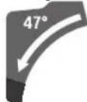
-Повачete ГДБerte NODEcINBn rpaHnHn BODnKn (7) COCEma Harope.
- OnaabaBete ro 3aterHyBaucknot noct (13).
-HabanejaIin3raKaTa paKa(23)Ha npKata (3)O 0'-no3njuMaNky HaNBO BpTeTe Ro BPNTNBO T KOnue (32),doEka He CE npKae cakaHNot BeTnKaJehoncer Ha aRONOT Ha zakocyBahe.
-HabanejaIin3rauKaTa paKa(23)co npKata(3) KOH IeBO HnI DecHO,ce DoJeKa aflomepoT (28) Hn (21) He To NOKaKyBa NocakyBaHHOT BepTKKaHeHa 3aKocyBaHe.
Држete ja nI3raKata paKa (23) BO Obaa no3uJa n NOBTOPO 3aterHete ro 3aterHyBaKnot loCT (13). Cnata Ha 3aterHyBaHe Ha 3aterHyBaKnot loCT Mopa da ja npKn CnrypHo no3uJaTa Ha nI3raKata paKa npN 6nNo KoJ BepTKaJIeH aOrn Ha 3akocyBaHe.
Iopocybahe Ha BepTNKaen cTaNapDeH aRon Ha 3aKocybahe 22,5° (BnHcNka K)
H3BneueTe ro konueTo 3a noDecyBaBe (29) cIeNoCHO haHaBOp H CBPTe Ro 3a 90^ .TIOToHa HabaneTe ja IIN3raKata paKa (23) Ha npkaTa (3),doKe He cnUHeTe Da ce BKnOHi.
CtabaBeBoynotpe6a
BknyBahe (BnHc nHa L)
-3a BknyyBaBe Ha eneKtpnHnot anat hajnpBO CTaBete ja 6nokaDATA npn BknyyBaBe (4)Ha cpeINHa n noToa npntncheTe ro npkeNHyBaOt 3a BknyyBaBe/ NcknyyBaBe (52) n DpxKeTe ro npNTnCHAT.
Hanomeha: Nopadn 6e36ednoch npnuHH npekHhyBaOH 3a BknyBaBe/HcknyuBaHe (52) He ce 6noknpa, TyKy Mopa nocTojaHO da Ce dpxnn pntncHa 3a BpeMe Ha pa6oTata.
NcknyuBaHbe
-3a NcknyBaBe OTnyTete ro npkeKNHyBaOT 3a BknyyBaBe/ncknyyBaBe (52).
OrpAHyBaHe Ha CTapTHaTcTpyja
EneKtpoHcKOTo OrpaHnUyBaHe Ha cTAPTHaTa CtpyJa ja
OrpaHnUyBa jaHNaTa Ha CtpyJATA npN BKnUyBaHe Ha
eNEKtpuHHOT anat N OBO3MoxyBa pa60ta Ha ocHpyBaOd
16-A.
Hanomeha: Iokonky ekeptnnoaI aIAT cTatyBa BeHaaw no BknyuBaHTo co noln bpoj Ha BpTeKn, orpaHcyBaHTo HA cTAPTha CTPyJa He paBoTn. EkeTpHNoT anat Mopa BeHaaw da ce HcnpaTH BO cepBnchata cnYkbA. Adpecn: CepBncha cnYkbA n cobetn npi KOpNCteHe.
Cobetnpa6oTeheTo
OnuTH HAnOMeHn 3a ceuebe
Cekoraw 3aterheTn KOnyTo 3a HkncpaBe (11) n 3aterhybaKnot NoCT (13) npedceyebeTo. Hnky ceHnIOTo 3a nnla MoXe Da Ce 3arnaBn BO denot wTO ce 6pa6OtyBa.
Cekoraw 3aterhybaje rK konyeTo 3a
Фнксраьe (11) n 3ate3Hnot noct nped ceyebeTo.
Инaky ceHHIoTO 3a nIIa MoKeJa Ce 3aIaBn BO DeJNot
шTo ce 6pb6OtuBa.
PnCtpepeoHajnpBO mopa da ceocnrypate,deKa ceHNOTo 3a HNA BO HNeEHN MOMHT Hema da ja JIOnpe rpaHnHaTa BOHnka, CTOnapckNte CTeH Nn Dpyrnte denOBn Ha ypeO. N3BaJeTe ro eBENTyAnHO MOHTpaHnOT NOMoWeH rpaHnHKn Hn COoDBeTHO NOdecete ro.
3aHTe ro ceHnTo 3a nHa od yapn. He ro H3NOxyBajTe CEHnOTo 3a NnHa cTpaHneH npntcOK.
Ceyete camo matepnjann, KOI ce do3BOJEN 3a HameHCKata ynotpe6a.
He 6pbotybajte NckpmbenH denOBn. Denot wto ce 6pbotyba mopa da hma cekoraw npab pa6 3a noctabyBahe Ha rpaHnHaTa BODnka.
IOnnnte n TeuKn denoBn 1to ce o6pa6oTyBaat mopa da ce notnpaHa cno6oDHNOT KpaHnn Da ce npncBpctat.
PpOBepTe dAnOcunatopHata 3aHTHa xay6 MoKe npABnHO da yHKUHOHPa n DaNNMOKe cNoBDoHa ce DnKn. Kora ja BOHTe paKaTa Ha aNtOT HAnony, Mopa da ro OTbOPHTe ocunatopHNOT 3aHTteH Kanak. Kora ro BOHTe paKaTa Ha anATot HArope, OCUNATOPHNOT 3aHTteH Kanak MOpA da Ce 3aTbOPn Npeky CeHHOT 3a NNJa Da CE fHKnPa BO HajropHa No3uJHa HA KpaKOT Ha anATOT.
Pto3njuHa KOpncnKoT (BmHcNkA M)
He 3actaHyBaJte BO eHa NHHJa co ceHnOto 3a nHa nped eneKtpnHnO anat, TyKc cekorau cTpaHnHO od ceHnOto 3a nHa. Ha toj hauHH, BaueTo Teno e 3aHTTeHO OD MOKeH NOBpAteH ydap.
-Држete rнДпанкite npctHTe npaTe nOdaNeky oD potnpaKOTO ceHNo 3a nHa.
-He rnppekpcTyBajTe dnaHKnTe nped paKaTa ha anaTOT.
MeHyBaBe Ha niooata 3a BMETHyBaBe (BnH cInka P)
UpBeHHTe nnou 3a BMeTHyBaHe (9) MoKe Da ro HCTpoWAt eNEKTPnHnO t anat no noonra ynotpe6a.
3aMeHete ja depekTHata nnoa 3a BMeTHyBaHe.
- PóndeceTe ro enektpnuyHnOt anat BO pa6oTHa no3nizja.
-0dBpTe rH 3aBPTKHe (53) co Knyu co BHaTpeWHa WecTaRnHa rnaBa (4 mm) (30) n H3BaTe rH CTapHTe NIOUH 3a BMETHyBaIbe.
-CTaBete ja HObata Decha NIOOa 3a BMETHyBaHbe.
-Пицьрстete ja nioуа ta 3a BmTeHyBaHe co 3aBpTkHe (53) WTo e MoXHo NOpECHO, Taka WTo NO ueNaTa ДОЛЖИHA Ha MOxHOT O nobIeKyBaHe Ha ceuNtO 3a ПпЯ Hema da doJde BO KOHTAKT CO nIOUaTa 3a BMeTHyBaHe.
-IOBTOpeTe rpaOHTHe YekOpn aHaIOrHO 3a HOBaTa IeBa IIoOa 3a BMETHyBaBe.
D03B0ENH DmHeH3nHa dIeNt wTo ce 6pa6OtyBa
MaKcHmAnHH denOBn 3a o6pa6oTKa:
| хорнотален агол на Зakocуbaьe | Вертыkanенагл над зakocуbaьe | Виснахшируна [MM] |
| 0° 0° | 80 x 306 | |
| 45° 0° | 80 x 216 | |
| 0° 45° (пебо) | 54 x 296 | |
| 0° 45° (десно) | 30 x 296 | |
| 45° 45° (пебо) | 54 x 208 | |
| 45° 45° (десно) | 30 x 208 |
MHHMaHn HENOBn 3a o6pa6oTKa (= CHTe HEnOBn WTo ce
O6pa6oTyBaAT, wTO MoKeJa Ce 3aTeHaT Co CTOnapcKa Ctera
(19) neBO HnH DecHO od CeuHnOto 3a Hna): 145 x 306 mm (DoljNHa X WnpHa)
MakchmamHa dla6oHuHa ha pe30T (0^ / 0^) : 100mm
Ceebe
Ceeybe 6e3 Bneuehe (OTcckyBahe) (BnHn Cnka N)
-ПиTNCHeTe jaIIN3raUkaTapaKa(23)IeNoCHOHaHa3aI nФИКСИРаTe ja BO OBAaNo3HuaJa.
IpoBepTe daI rpaHnHnKOT 3a dna6oynHa (25) e npHTNCHAT cENOCHO HaBHATpe H3ABPTkata 3a noDecyBaHe (24) npIN DBHXeBeTo Ha IIN3raQKaTa paQKa MHHyBa Hn3 OTBOPOT 6e3 da Ro DOnpe rpaHnHnKOT 3a dna6oynHa.
-Пицьрсте ro DeIOT wTO ce 6pa60TyBa cornaCHO dHMeH3HHTe.
-No notpe6a noctabete ro cakahnot aorn ha 3akocybahe (xopn3oHTanen H/nnn BeptnkaneH).
-Bknyte ro eneKtpnHnot anat.
-Понeca BOпete ja HaДony ПИЗгачkaраз paчka (23) co Дршкага (3).
- CeueTe ro denot wTo ce o6pa6oTyBa co nct npntucok.
IcknyeTe ro eNEKTPnHNOt anat n NOeKaTe DoEka ceuNoto 3a Nnla He doJne cenoCHO BO COcTo6a Ha MnpyBaHe.
- Poneka Bodeje ja nizraqukata paKa (23) Harope.
Ceehe coBnehe (BnH cInka O)
Ubpcto DpKTe ja dpkKaTnpeBKnlyyBaHTo n3a Bpeme Ha ceNoKynHnO Tnpoc H caceHe. Co IIN3raKATA paKA KOHTPOInpajte To DBHXeBeTo 3a Bpeme Ha ceeHeTo. EeH MOMENT Ha HeBHIMAHne CO ekCTpeMHO JECHO NOBHNHaTnN3raKa paKa MoKe da DOBeDe IO cepNo3HH NOBpeHn.
-1e6noKaHa Ha n3raKaTa paKa (23). Co hBNeKyBaHe H NOBKeYBaBe Ha3aHaJIHraKaTa paKa (23).IPOBepTe DaH N KOMPnEThNOT IIN3raKmexAH3a e NOTROBEN 3a pIMMeHa.
-Пицьрстето Гдот StTo ce 6pa60TuBa cornacho DmmeH3nTe.
- IIO notpe6a noctabete ro cakahnot aorn Ha 3akocyBaHe (xopn30HTanen H/nnn BepTNkaneH).
-Помсетete ja Изгачкata paika (23) co Дшka tata (3) on rpaHnHaTbOdInka (8),doKeKa ceuHnTo 3a ПнlaTa He ce Hajnde nped denot 3a o6pa6oTKa.
Bknnyute ro nektpnHnoT aalT. - Poneka Bojete ja Haidony Nn3raKaTa paKa (23) co DpuKata (3).
-Cera npntnche ja n3raqukata paoka (23) BO npabeu Ha rpaHnHaTbOAnka (8) HceTe ro denot 3a o6pa6oTKa co eDnKOB npNTcOK. - Ncknyte ro eneKtpnHnot anat n noeKaTe doeKa ceuNto 3a nHa He JoJe cenocho BO cocto6a Ha MnpyBahe.
-Полеса ВODEte ja Израчкага рачka (23) Harope.
IpoecyBaIbe Ha rpaHnHHKOT 3a Ia6OuHa (ceyeHe Ha Kne6) (Bnu n CnKa Q)
「pahHMHKOT3aDnabOCHHaMOPaDaTgONMeCTHe,DOKOKy cakate Da HceueTe Kne6nn Da ynoTpe6teNtctanep.
-CbpTeTe ro TpaHnUHKoT 3a JnaBouuHa (25) KOH HauBOp.
-Habane ja nI3raqukata paKa (23)Ha npKata (3)BO cakaHaTnO3nJa.
-Cbptete ja 3aBpTkata 3a noDecyBaBe (24),doNeKa KpaJot Ha 3aBpTkata He ro Donpe rpaHnHnKOT 3a Dna6oHnA (25).
-Понeca Ворете щлзгачкata paчka (23) Harope.
Cneunjannn denobn 3a 06pa6oTKa
PnCceHe Ha CBNTKaHn TPKaJIe3Hn DeNoBn 3a
ObpaBoTKa, MopAoobpo Da nObe6eBeIne OnIINrBaHe. Ha
HnHjata Ha ceYeHe He CMeE Da NoCTOn IPoUeM EMyDeNt
To Ce o6paboTyBa, rpaHnHaTa BODnKa H Macata 3a Nnna.
Dokonky e Notpe6Ho, MopA Da HAnPaBIne CneuJaanH
dPkaH.
06pa6oTKa Ha npoΦnHH najchN
IpoΦHnHTe IajChn MoKe Da ce o6pa6oTyBaAT Ha Dba pa3NJuH HauHH:
| Позицонпаны наделотшто се образува | Позицонпаны ларфонски лajсни |
| - поставец КОН грашинасы Вордени | |
| - постато лженьки на Масага за пленa |
PnoHaTamy, He3aBnCHO OJ shnPnHata Ha npOoHnHa Iajcha, MoKe da ceyete co nIe NOBNeKyBaHe.
CekoraI npOBepTe ro noCTaBeHnO t aOr I Ha 3aKocyBaHe (xOpN3oHTaIeH H/nn BepTnKaIeH) HajnpBO Ha OTnAdHO dpBO.
PpOBepKa HnoDecyBaBe Ha OCHOBHnTe NOCTaBKn
3a rapaHTnpaHe Ha npeun3n pe3OBn Mpa Da rI npOBeprte OCHOBHnTE NOCTABNIO NHTEH3NBHO KOPNCHe Ha eNEKTPnHnO tAnT H EBEHTyAHLNo Da rN NODECnTe.
3aToaBn e nOtpe6Ho NCKyCTBO H COODBeTeH CneuJaJeH anat.
CepBnchata cnyyka ha Bosch obaa pa6ota ja BOIN npeun3HO IOBepnBO.
IopcCyBaBe Ha BepTKKanEn CTaHapDeH aron Ha 3akocyBaBe 0^
-NoodeceTe ro eNeKtpuHnO t aIaT BO TpaHCnOpTHa n03nju.
-Cbptete ja macata 3a nna (33)do kne60r (14)3a 0^ PaKaTata (12) mopa ocTeHO da ce BKnOIO BO kne60r.
PpOBeRka(BHnCnKaR1)
- Noctabete ro arnomepot 90° n ctabete ro Ha Macata 3a nnna (33).
KpaKOT Ha arnomepot Mopa da 6nne npeun3en no cenata dONXHACo CEuNTO3a Nna (34).
ToodecyBaHe (BnHn CnNkA R2)
- Ona6abete ja 3aTe3HaTa paKa (13).
-OnababeTe rN DBeTe 3aBpTKn 3a NOdecyBaHe (54) (HajMaIKy 1 BpTeHe) co Kny 3a BTNCHyBaHe (10 mm). - Ona6abete ja 3aBpTKata 3a nopeCyBahe (56) (okony 3 BpTeHa) co Knyu co BHaTpeHnHa WectarOnHa rnaBa (4 mm) (30).
-3abptete ja nnoobptete ja 3aabptkata 3a nodecyaBahe (55) co knyu co Bnatpehna wectaronha rnaBa (4mm) (30),dokeka Kpakot Ha aronHTo MepnHe Hae Hae He no cenata dojnxHa co ceunno To 3a nila.
-ПОТOPНО CBPCTO CTERHETe ja 3aTe3HaTpaUka(13). ПOTOA IIPOBO 3ATERHETe ja 3aBPTKaTa 3a NOdecyBaHe (56) И NOTOa 3aBPTKIne 3a NOdecyBaHe (54).
Дokonky arnomepot (28)и (21) no nodecyBaHeto He e BO Лннja co O'-03нakite Ha cKaIATA (27), ona6abete rN ЗВТКИTE 3a NOdecyBaHbe Ha aTnOMePOT CO KpCTeT ОДВТуВач ИЗрAMHete ro arnomepOT nOДЖИHA ha O'-O3HaKITE.
IopecyBaBe Ha BepTKKanHHOT cTaNdapDeH aron Ha 3akocyBaBe 45^ (neBO)
- Pnoecete ro eeneKtpnHnO anat Bo pa6oTHa no3nuija.
-Cbptete ja macata 3a nna (33)do jne60r (14)3a 0^ PaKaTa (12) mopa ocTeHO da ce BKnOIO BO jne60r.
-LeNoCHO H3BneYe ta HaHaBOp IeBaTa NoDecnBa rpaHnHa BOuNkA (7).
-OnabaBe ja 3aTe3HaTa paKa (13) n Habanete ja nnraKaTpaKaHa npKata (3)do KpaJBO neBO (45^)
ToodeCyBaBe(BHnCnKaS2)
-3aBPTe ja nn Odbptete ja 3aBpTkata 3a noDecyBahe (57) co knyu co KpuKanka (8 mm),doKeKa pakot Ha arONHTo Mepnno He ce npeKnOnn No cenata DonxHa CO CEHNTO 3a Hna.
-Повторноцьрстсгене Гаaterнвачкnot loct(13). Ako arnomepot (28)и (21) no NOdecvbaheTo He e BO edha nHHja co 45^ -O3Haknte Ha ckanata (27),npOBepete ja yuTe ednaW O-noCTaBkata 3a aroJOT Ha 3aKocyBaHe n POKa3aTeNoT Ha aroJOT. ITOta NObTopeTe GnoDECyBaHeTo 3a BepTKaHnOt 45'-arOn Ha 3aKocyBaHe.
BepTKaJIeH cTaNdApDHe arON Ha 3akocyBaIbe 45^ (decho)
- Pnoecete ro eleektpnHHT anat BO pa60tha no3nua.
-CBpTeTe ja Macata 3a nHa (33)do Jxne60r (14) 3a 0^ PaKaTa (12) mopa ocetHO da ce BKnONn BO xne60r.
-ИЗБЕЧЕТа ДЕСНА ПОДECПИВА ГАПИЧА ВОДИКА (7)
цносно HaHaDВОр. - Ona6abete ja 3aTe3nata pauka (13).
-HaBaneJaHn3raKaTa paKaHaDpKata (3)O O-no3njuMaNky HaneBO H BPTeTe R BPtNBOTo KOnue (32),doEka He ce npKakae BeptkAaHnOT ONcer Ha aTOnot Ha 3aKocyBaHe.

-Habane ja nI3raVkata paKa Ha npkata (3)Hapecho do KpaJ (45°).
IopecyBaBe(BHnCnNkA T2)
-3aBpTe je nnOdBpTe ja 3aBpTkata 3a noDecyBaHe (58) co Knyu co KpuKanka (8 mm),doEka KpaKot Ha aRrHTo MepnNo He ce npeKnOnn No eNaTa DOnxHaCo CEHNTO 3a Hna.
- NOBTOPHO UBCPTO cTERHeTe rO 3ATERHYBaUKnOT IocT (13). Ako aRrnomepoT (28) n (21) no NOdecyBaBeTo He e BO eHa nnHnJa co 45^ -03NaKeIte Ha cKaIaTa (27), npOBepeTe ja yuTe edHaW O-noCTaBkata 3a arONot Ha 3aKocCyBaHe n pOKa3aTeNoT Ha aROJOT. ITOta NObTopeTe rO NOdecyBaBeTo 3a BepTKaINHOT 45^ -arOn Ha 3akocCyBaHe.
H3paMHyBaBe Ha cKaIata 3a XOpN3oHTaneH aRon Ha 3aKocyBaBe
- Pnoecete ro eeneKtpnuyHnot anat Bo pa60tha no3nuija.
-Cbptete ja macata 3a nna (33)do kne60r (14) 3a 0^ PaKaTATA (12) mopa ocetHO da ce Bknonn BO kne60r.
IopecyBaBe(BnHnCnNkaU2)
- Ona6abete r n CHTe ueHn3aBPTK 3a noDecyBahe (59) co Kny CO BHaTeWHa WecTaRonHa rnaBa (4mm) (30) CBPTe ja MacaTa 3a Nla (33) 3aeHNO co cKaIaTa (31),
Dódeka KpaKOT Ha aIOMepOT He IeXn paMHO no cenaTa DOnxHa Ha CeuNtO 3a nnla.
-IOBTOPOHO3aTeHHeTe r3aBPTKHTe.
Iokony no noecyBaHeto arnomepot (51) He e BO liHHja co 0^ -o3HaKaTata Ha ckanata (31), onababe ja 3aBpTKata (60) co oBnueh Kpctcct ODbtpYbau Hacouete ro aIromepot nOdoJHKnHa Ha 0^ -o3HaKata.
IopocyBaBe Ha cInaTa Ha 3aTeHyBaBe Ha 3aTeHyBaKnOT NoCT (13) (BnDn CnKa V)
CnIaTaHa3aTeHyBaHbHa 3aTeHyBaKnot NoCT(13)MOKe DOnONHITeHNO Da CE NOCTaBYBa.
Поберка
-CinataHa3aterHyBaBeHa3aterHyBaKnotIOCTMopaJa dpxN Cnrypno No3njuata Ha N3raKaTa paKa np6HNO KOJ BepTnKaIeH aOrn Ha 3akocyBaBe.
TndecyBahe
- Ona6abete ja 3aTe3HaTa paKa (13).
-Cbptete ja 3aBpTkata 3a noDcCyBahe (61) co kny 3a BTHCHyBaHe (17 mm) BO npaBeu cnpOTHBEN Ha CTpeKNITE Ha yacOBHNKOT, 3a da ja HA mAnITE CnnaTt Ha 3aterHyBaHbe Hn CBPTeJa BO pNaBeu Ha CTpeKNITE Ha yacOBHNKOT 3a da ja 3roIemnte CnntaHa 3aterHyBaHe. - NocTaBeTBeBepTKaJIeH aOrI Ha 3aKocyBaHbe, NOBtOPO hBpCTo 3aTeRHeTe Ro 3aTeRHyBaUKnOT IocT (13) nPbOBePeTe DaIIe NoCTrHHaTa NocakyBaHaTa Cnla Ha 3aTeRHyBaHc.
TpaHcnpot(BnDnCnKaW)
IpeTpaHcnpOTHa eJektpuHnO t anat Mopa da Hn3BpHTe CneHnTe YekOpH:
-Пинсichte ja nI3raqukata paKa (23) ZeIocHO HaHa3aI nФИКСИРAJTe ja BO OBa aNo3uJa (BnDn,OCHrypyBaHe haIIraqukata paKa", cTpaHua 23).
-Провете ддграчнкота длбочин(a25)e npHTCHATцELOCHO habHATpe n3aBpTKaTa 3a NOdecyBaHe(24)pINДВЖeHToHaKpaKOTHa anaTOT MHyBa Hn3 OTbOpot6e3 da ro donpe rpaHnHKnOT3a dna6oHHa.
Bodete ja nnaa kata paka haonnydoekatpaHCnoptHNOtOCnrypByaue (26) cenocho he ce npntnche HABHaTe.
-BMeTHeTe ro npoOJKNHNOt dpKaU (16) cenocho HABHaTe.
-NotaBeBepTnKaenArOHa3akocyBaHeo0N UBCPo3aTeHrEte Ro3aTeHyBaUKnOT NoCT (13).
-Cbptete ja Macata 3a nna (33)do KpaJ ha neBOI 3aterHETe ro konyeto 3a qKcnpahe (11).
-Bp3eTe ro ctpyHnO Ka6en co IennBata IeHTa (62).
-OTCTpaHete HENDEIOBHTHaONpeMaT,KHO MEMOE UBCPTO Da CE MOHTnPaAT Ha eNEKTPNHNOT aIaT.
-CTaBeTe HHeNCKOpHcTe HeHtce CeyHla 3a Nnla BO 3aTBopeHa KytJa, DOKoKny CaKaTe Da TpaHCnopTpapte.
-EnKTPnHHTpyeHnocTeToTakaIITQKNe6OBNTe3a DpKeHe (17)KeIhΦaHTeOcTpaHaTaHaMaCata3a ceueHe.
PnTpaHcnpoHa eNeKtpHnHOT anat KopHcTeTa camo TpaHcnpOTHypeu, aHKoraw 3aWTHTHypeu, nH3raUka paUka (23) nn npka (3).
OdpkUBaHe n cepBnC
OdpKyBaBe n uHCTeHe
Ppe6nno KaKbA HHTepBHeuJa Ha eEnktpHnnot anat, h3Bneye ro ctpyjHnO npKnnyoK od smHaTa 03Ha.
OpjxBajTe rHcTHe eneKTPnHHOT aHaT h OTbOPHTe 3a npoBeTpYBaHe, 3a da MoKe do6po H 6e36eHDo da pa6oHTe.
Iokonye nortep6Ho KopncTeHe Ha npknnyeH Ka6en, ToraHnababe ro od Bosch HnCneuJann3npaHa npodabHnca 3a Bosch-eneKtpnHn anatn, 3a da n36erHete 3arpo3yBahe Ha 6e36edHocTa.
OcunatopHnOT 3aHTHeK Kanak Mopa cekoraa Da ce DbHexn Cno6oHn n CamocToJHO da ce 3aTbopa. IpeJeNoT Okony OCunatopHnOT 3aHTeH Kanak cekoraa Tpe6a Da 6nde qHCT.
OTcpaHe ja npaBtN CTpyroTHHnTe co N3dyByBaHc CO KOMPecnpaB03dyx HnN Co YeTKa No cekoja pa6oTHa NOCTaNA.
- PeIOBHO UHCTeTe ro nI3raKnot BaJIaK (20) I nI3raKaTpaKa (23).
Onpema
| Бpoj на颇/ apтник | |
| Столарская сtera 1 609 B06 203 | |
| Плочи за Вмetedувае 1 609 B04 263 | |
| 1 609 B04 264 | |
| Кеса за прав 1 609 B02 595 | |
| Адалтетер за BCИСУBAьe 2 607 001 977 | |
| Вaxки за сладнист StINOB:3 601 M27 04./_... OL./_... 08./_... 0B./_... 0K. | |
| Сецilla за пILA за ДрBo и пLoveст MaTeprjann,панели и лajсни | |
| Сецillo за пILA 254 x 25,4 mm, 403anц | 2 608 676 047 |
| Сецilla за пILA за CBPSTо ДрBo, KompoэntнmaTeprjann, Пл actнka и Неметали | |
| Сецillo за пILA 254 x 25,4 mm, 403anц | 2 608 640 969 |
| Сецillo за пILA 254 x 25,4 mm, 403anц | 2 608 640 970 |
| Сецillo за пILA 254 x 25,4 mm, 403anц | 2 608 640 971 |
Bpoj ha den/ apTNI
| Вaxи 3a сеДнITE TИNOВ:3601 M27 00./_03./_07./_06. | |
| Сецни за пида дрво и пioочту Матерни,палени и лajсни | |
| Сецни за пида 254 x 30 mm, 403anцi | 2608642530 |
| Сецни за пида за CBPCTO дрво, КOMПОЗHTMIMatерни, пл actнka и Неметаи | |
| Сецни за пида 254 x 30 mm, 803anцi | 2608642528 |
CepBncha cnyK6a n COBET np KOpHCTeBe
CepBnchata Cnyk6a Ke OndroBOpn Ha BaWnte npaaHb BO BpCKa co nonpaBkata N odpxyBaHbTe Ho Ha BaWnOT npOn3BOD KaKo Hpe3epBNHTe DeNoBn. O3HaKn 3a ekCnIoo3nJa n INHΦopMaun 3a pe3epBNHTe DeNoBn IcTo Taka Ke HajDeTe Ha: www.bosch-pt.com
TMMOT 3a COBetyBaBe npK KOpNCTeHe Ha Bosch Ke BN NOMORHe DOKOLky HMaTe PpaAhaBa 3a HaaHTe NpOHN3BODN INonpeMa.
3a CNTe npaaHbN HapaKHa pe3epBn DenoBn,Be MoIInme HabeTe ro 10-ΦpeHnot 6poj od CneuKauHata IIouka Ha npoun3BOJOT.
CebepHa MaKeDoHja
Д.Д.Енковс
CabaKobayek47b,6poj3
1000 Ckonje
E-nowta: dimce.dimcev@servis-bosch.mk
HHTepHet: www.servis-bosch.mk
Ten./φακc:02/2467610
Mo6.:070595888
Д.П.T.Y "POJKA"
JaHnyKpOBcKn 66;T.U ABToKOMaHaJn oKaI 69
1000 Ckonje
E-nowta: servisrojka@yahoo.com
Ten: +389 2 3174-303
Mo6: +389 70 388-520, -530
DOnonHHTeHH aDpeCN Ha cepBnCH MoKe da HajTe NOI:
www.bosch-pt.com/serviceaddresses
OtctpaHyBaBe
EneKtpnHHTe anaTH, onpMaTa n am6aJaxHe Tpe6a da ce oTcpaHaT Ha ekoIouknpuafNHB HauHH.
He nI pnpajTe eneKtpnHHTe anaTH BO DOMaunHaT KaNTa 3a OTnadoOn!
Cama 3a 3emjnte oEY:
CnopeE Ebponckata perynatna 2012/19/EU 3a eNektpnHn n enektpoHcN ypeu HmBhata
IMNIIEMeHTaUJa BO HaCNoHaHnHO TpaBO, eNeKTPuHnTe
340 | Srpski
anaTHIto CE BOH ynoTpe6a Mopa OdoJIeHNO da CE cO6npaAT n da ce peuKlnpaat Ha ekONoUKN npnfaTnB HauHH. DOKONky CE oCTpaHybaa THePabINHO, eNEKTPNHATA n ENEKTPOHCKata ONpema MoKeJa NMaat WTeTHN BInjAHJa BP3 KINBOTHaTcpeINHa N3dPaJbETo Ha NyfeTo nopadn MOKHOTO pncyctBO Ha ONACHN MaTePHN.
Srpski
www.bosch-pt.com/serviceaddresses
Uklanjanedubreta
www.bosch-pt.com/serviceaddresses
Odlaganje
Elektricno orodje, pribor in embalzo je treba dostaviti v okolju prijazno ponovno predelavo.
www.bosch-pt.com/serviceaddresses
Zbrinjavanje
Uldised ohutusnouded
HOIATUS
Veel juhiseid: Transport
Profiillistude tootlemine
www.bosch-pt.com/serviceaddresses
Pärbaude (attels U1)
- lestatiet uz lenkmera lenki 90^ un tad novietojiet to starp vadotni (8) un zaga asmeni (34) uz zagesanas galda (33). Lenkmera mertienim visa garuma ciesi japiespiezas zaga asmenim (34).
www.bosch-pt.com/serviceaddresses
www.bosch-pt.com/serviceaddresses
Salinimas
- 修正同公格到当的高定整则为承用者,
华 - 修正同公之A相本部在中中中中中中中中中中中中中中中中中中中中中中中中中中中中中中中中中中中中中中中中中中中中中中中中中中中中中中中中中中中中中中中中中中中中中中中中中中中中中中中中中中中中中中中中中中中中中中中中中中中中
保専専達日士連三用之
(GTA 2500 W, GTA 3700, GTA 3800)
述者,如:
-龍達藥藥藻藻藻藻藻藻藻藻藻藻藻藻藻藻藻藻藻藻藻藻藻藻藻藻藻藻藻藻藻藻藻藻藻藻藻藻藻藻藻藻藻藻藻藻藻藻藻藻藻藻藻藻藻藻藻藻藻藻藻藻藻藻藻藻藻藻藻藻藻藻藻藻藻藻藻藻藻藻藻藻藻藻藻藻
- -
一P2a
自用用国
(204 作業工場の基層の基層の基層の基層の基層の基層の基層の基層の基層の基層の基層の基層の基層の基層の基層の基層の基層の基層の基層の基層の基層の基層の基層の基層の基層の基層の基層の基層の基層の基層の基層の基層の基層の基層之
www.bosch-pt.com/serviceaddresses
司
lloIocbauuHuaaHuaHuaHuaHuaHuaHuaHuaHuaHuaHuaHuaHuaHuaHuaHuaHuaHuaHuaHuaHuaHuaHuaHuaHuaHuaHuaHuaHuaHuaHuaHuaHuaHuaHuaHuaHuaHuaHuaHuaHuaHuaHuaHuaHuaHuaHuaHuaHuaHuaHuaHUA
jL
yJxS1Uo21
USSu dLg U
4j020 1bui j a
Jol
40 aJUgSJJ
aogolbawu
4gJUboKJcA
山LJpddm
UjjaiJIa aJluJe
g pksy Ibaog LsO y aLlU aay aalw oIc y c sog 13. yu L uus Jbua Ung Ssw g uiaa l jao ay aLlau aoulo .jno ay aLoU uosseil no sljio .6aui
aal no 15 ola jy g abolay culll l uall aabg paa x. alglag ng y" Ugalal no la g bao xg aoai gl aullucu wog . "oclua uilw g dall ocawly loall sic g sdd asoi all .bloq
aabg Jaaagjuaia I aegg gagwlg juaiaIg Jaaal Jgagg JgJgJg Jg Jg Jg Jg Jg Jg Jg Jg Jg Jg Jg Jg Jg Jg Jg Jg Jg Jg Jg Jg Jg Jg Jg Jg Jg Jg Jg Jg Jg Jg Jg Jg Jg Jg Jg Jg Jg Jg Jg Jg Jg Jg Jg Jg Jg Jg Jg Jg Jg Jg
Jaiiaol o jai gI plai IgW JaiJI 10aio gG y d 1jwll aagpucu u Jn 1y 1y 1y 1y 1y 1y 1y 1y 1y 1y
aJj Jnll 00100 100 n jg sI aaw g g aai Jn Jnll Jnll oJy Jn Jn Jn Jn Jn Jn Jn Jn Jn Jn Jn Jn Jn Jn Jn Jn Jn Jn Jn Jn Jn Jn Jn Jn Jn Jn Jn Jn Jn Jn Jn Jn Jn Jn Jn Jn Jn Jn
gaggl gaaagaaaagaaagaaagaaagaaagaaagaaagaaagaaagaaagaaagaaagaaagaaagaaagaaagaaagaaagaaagaaagaaagaaagaaagaaagaaagaaagaaagaaagaaagaaagaaagaaagaaagaaagaaagaaagaaagaaagaaagaaagaaagaaagaaagaaagaaagaaagaaagaaagaaagaaagaaagaaa
8 2 aag g aalg w g ag g g g g g g g g g g g g g g g g g g g g g g g g g g g g g g g g g g g g g g
2 aaslll o ydsll l g b g j C 1
g wu w s g, g y u Ls la Lg c g gl laba
Lil f jw d g gl JuaiaI Ijaw asd qla
. gbl
J 1000000000000000000000000000000000000000000000000000000000
Jusill elioo jzjg Ls oal Jssll .Ldol!u uug aabmu lablg
jIJI I bJg JALU Lg 13! pSJIJI JNJ gJ UJSSJU
<aoSagduUjtaaillagbdkngsiojqll .Jgao uJsu aju
8.1JbIJIgUeSJJdJIyIaIJI 8.JIbIJI Uglio JcI JgOlaI
aJQJUgSJI 1I I
J. Laiu Jll Uj jol g
jg jol gol ssiw ju jobaa yjSJI
A. 与 x 无关
a aas jai jai jai jai sui .d aas jai n c aaaiaa m g p w l k s u o gss o jai dui cils i lo aagg 0d d a a a a a
ailll jzI 100! yu. ayljySLI 1slln jyLL Jyssw oLc! jg kuiu uu uuuu uuuu uuuu
aBbll bgggblao gog 5y
yllsallgallgsaalssse j IeaggnsoguJlsuuaIgul
Lai aalalalalalalalalalalalalalalalalalalalalalalalalalalal
4.2aJI. 100000000000000000000000000000000000000000000000000000000000000000000
do
abg Jlsswlg juaaiaJI Jlaell abwg. 1c abglall uJnB aJUJI JlaJI .JalI Uloi
a
Jg yg 1yaguall aaiall gablaaalgbalgo lgaaswul jllg uall
4.00 J 1234567890123456789012345678901234567890123456789012345678901234567890123456789012345678901234567890123456789
4Lc ggo gJ Jnulll Juaio u Sli Uaill aab pCi alla g.ullu 1u 1u 1u 1u 1u 1u 1u 1u 1u 1u 1u 1u 1u 1u 1u 1u 1u 1u 1u 1u 1u 1u 1u 1u 1u 1u 1u 1u 1u 1u 1u 1u 1u 100 u Jai X aalal Juaia I jaa Juaa gbbgbal JuaiaI I aai
gI/gJooJI
SswuLalJg
- öslag àójbi gbi
A
auiuJc
a
U!JauWl aebpa
435
gui J1 1s g jg s oJ gj uill
uJusu 1s uo jao Jgall
Jl JJI g Jgulggl aee wll JIJI g JIJI JIJI JIJI JIJI JIJI JIJI JIJI JIJI JIJI JIJI JIJI JIJI JIJI JIJI JIJI JIJI JIJI JIJI JIJI JIJI JIJI JIJI JIJI JIJI JIJI JIJI JIJI JIJI JIJI JIJI JIJI JIJI JIJI JIJI
OeJUUOWUJI AULWJLJLLJ3gJU JUAIJI (HSS 3g9) aJUJI JgwwuK
(yssu llo)s wlaog aaii juiiaill Jai. gglgagglil jall uic sila jsw jg sww liaiial kj 1kaill udd q ciuy lao
0000000000000000000000000000000000000000000000000000000000
.0sui Jaii Juaiai Jaaa
jgol
J 1000000000000000000000000000000000000000000000000000000000000000000000000
liang jgqjll
jill gai jno kdy ydd X 9. aui jssll oell Joc li 0raaawolso sic uylolJuaill
JUgU Eu-1JJp 1JUJI
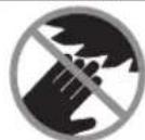
.

ggbalgljlllglballagljbgaog 1 jus kssn baaa aai 5u 12x g jaoi aabg pucil 《山》Ug.aaolplajg o
a aalaaa aaa aaa aaa aaa aaa aaa aaa aaa aaa aaa aaa aaa aaa aaa aaa aaa aaa aaa aaa aaa aaa aaa aaa aaa aaa aaa aaa aaa aaa aaa aaa aaa aaa aaa aaa aaa aaa aaa aaa aaa aaa aaa aaa aaa aaa aaa aaa aaa aaa aaa a aa
abol dIag JluiJolgagJglJI
a aalag aalag aalag aalag aalag aalag aalag aalag aalag aalag aalag aalag aalag aalag aalag aalag aalag aalag aalag aalag aalag aalag aalag aalag aalag aalag aalag aalag aalag aalag aalag aalag aalag aalag
abai jiuall ie pucuulg .glowpccss gl g ooiuall aegl c uusuuiu uusuauu uuuu uuuu uuuu uuuu uuuu uuuu uuuu uuuu uuuu uuuu uuuu uuuu uuuu uuuu uuuu uuuu uuuu uuuu uuuu uuuu uuuu uuuu uuuu uuuu uuuu uuuu uuuu uuuu uuuu uuuu uuuu uuuu uuuu uuuuu
JwJI Jaw aaggo gJwog
g jao aolll c1s lgl J 1000000000000000000000000000000000000000000000000000
| liligjglll |
| jlllgljgjlmll |
| jlllgljgjlmll |
| jlllgljgjlmll |
| jlllgljgjlmll |
| jlllgljgjlmll |
| jlllgljgjlmll |
| jlllgljgjlmll |
| jlllgljgjlmll |
| jlllgljgjlmll |
| lilg jlll |
| jlllgljgjlmll |
| jlllgljgjlmll |
| jlllgljgjlmll |
| jlllgljgjlmll |
| jlllgljgjlmll |
| jlllgljgjlmll |
| jlllgljgjlmll |
| jlllgljgjlmll |
| lilisagjogll |
| lilisall jbjg jbjg jbjg jbjg jbjg jbjg jbjg jbjg jbjg jbjg jbjg jbjg jbjg jbjg jbjg jbjg jbjg jbjg jbjg jbjg jbjg jbjg jbjg jbjg jbjg jbjg jbjg jbjg jbjg jbjg jbjg jbjg jbjg jbjg jbjg jbjg jbjg jbjg jbjg jbjg jbjg jbjg jbjg jbjg jbjg jbjg jbjg jbjg jbjg jbjg jbjg jbjg jbjg jbjg jbjg jbjg jbjg jbjg jbjg jbjg jbjg jbjg jbjg jbjg jbjg jbjg jbjg jajg jajg jajg jajg jajg jajg jajg jajg jajg jajg jajg jajg jajg jajg jajg jajg jajg jajg jajg jajg jajg jajg jajg jajg jajg jajg jajg jajg jajg jajg jajg jajg jajg jajt |
437
(bgall jil) wgl lssll 10000000000000000000000000000000000000000000000000000000000000000000000000
glll (16) wgal sall l 33 doaal jwial ocl awlia glll lolai jjll lglll p -
ai jgjol oal ayjgl sll oal jg j 00 00 00 00 00 00 00 00 00 00 00 00 00 00 00 00 00 00 00 00 00 00 00 00 00 00 00 00 00 00 00 00 00 00
(11) Cui 1
-uuu aabgjo (13
(18)gjglsg (16)gall saoi g -
(1) J_cJ_uS-
(30)gJJIWJILWJSLaio
(19)dojoll
1 1
Jg Jg Jg Jg Jg Jg Jg Jg Jg Jg Jg Jg Jg Jg Jg Jg Jg Jg Jg Jg Jg Jg Jg Jg Jg Jg Jg Jg Jg Jg Jg Jg Jg Jg Jg Jg Jg Jg Jg Jg Jg Jg Jg Jg Jg Jg Jg Jg Jg Jg Jg
sall jc aalj aglll aluysll sall 1gall ljagai dgaaoa
jull aullao gcly elao 8:wlao ablawg lao - ggl aulog qalab jilao (p017g0010:luo)
0JJI JJI UJS
j 1 j 1 - j 1 1 1 1 1 1 1 1 1 1 1 1 1 1 1 1 1 1 1 1 1 1
439
JJI:UdJjJ 0
gjgljdd
abwglg (23) gjg jg jg jw kswk wg .(2)gjjg
(b)
JolS Jsw plo81 gai jjglj jw - (aogjoll jill aeg)
(B1 oJgJJI jJI) gJyI gJ3 JLoJd
oJ (23) oJla lalks gjI aJI yaw Jg jI eJ IaJg J 10 J 10 J 10 J 10 J 10 J 10 J 10 J 10 J 10 J 10 J 10 J 10 J 10 J 10 J 10 J 10 J 10 J 10 J 10 J 10 J 10 J 10 J 10 J 10 J 10 J 1
jIJI jJl jJl JJl JJl
(B2 0jJ1 jJI) jjI j
JolK Jckw CaiIg jzjE jz
j21 1y jglal jlaaai liaaai aai - gao gagac kuy
julwll juiuaii jieboll jy jill joi jxj
g gJ (23) 1j 1j j j j j j j j j j j j j j j j j j j j j j j j j j j j j j j j j j j j j j j j j j j
:JolS Jswplo81 gai gjjEi jaw
Jplojg23) j
Jolssuaw aalg yjaiw uai jai
Jn Jn Jn Jn Jn Jn Jn Jn Jn Jn Jn Jn Jn Jn Jn Jn Jn Jn Jn Jn Jn Jn Jn Jn Jn Jn Jn Jn Jn Jn Jn Jn Jn Jn Jn Jn Jn Jn
.
Jaull qaiill
(Cgjgljil)laiiaIdd
Lqui aIgbl JwI g 1 jj j L .Lo Lw Lc aIwI
Juiuill ocl Jaiil aabg sinmu jSj Saa 11 (16) nww gail dy dail yabwgl .Juwgl g
1J11118j11j10
(16) uwwgall yssal l waa - (wag) ggeall gbll gogll jai 204
gjjjgljdsjssaJnwwgaiySaaJIyCoo 10
(D-E jgJl jai) aoslaaJdS W d
-abwglgulgl
.(40)gaiI 5
-abw|g(43) g
(30) (aa 6) aasll wlll wlaew elaoi
-ogglogsoo(42)i
(43)gglwJlIyWdGgUeJgUu(jli)aclwUfLac aJol .
.(44)aai
.34juaiaai jao
jwiai jaoa 5
4aolglggu
go (JwaiI Jai Lc pWll oJil) Jiw! IaLgill Ubc Lc pWll oJil
sic uSjll lq quSj Ug ball |jz jg.
.45)
-awllo Lc osy
-ωlωωgUg44
(43)govJwJU 120gj(42)JgJU 1uJGJU 1uJU
.(40)
-(40)+ (4:
a g1j (28) a g1j wgo u j l u wlll 1g 1u 1u 1u 1u 1u 1u
-1gglgglq
pLg (13) wUJ
gog baall gao gog c w l g iu 1 u 1 u 1 u 1 u 1 u 1 u 1 u 1 u
0) iaii aegll uaiuill aglj Jao bia (J ojgl jil) (45
.(52)/Uuui UaJUaJU
山
16 1
1gJgJgJgJgJgJgJgJgJgJgJgJgJgJgJgJgJgJgJgJgJgJgJgJgJgJgJgJgJgJgJgJgJgJgJgJgJgJgJgJgJgJgJgJgJgJgJgJgJgJg
Jus Js
yueu wao 2g. jai lai pksy
6jw yaiwi 8g. jill lqI Jswiab
aai 2 jaiai aai i jai ai
jai no gip jaiall giaoslaal asw
aigaaiaiaiaaaii .cg g i jagll
.aaiaill kswylg
J 2.1g jllg lao Jn Juaiaai Jaa J aai Jaa Jaa Jaa Jaa Jaa Jaa Jaa Jaa Jaa Jaa Jaa Jaa Jaa Jaa Jaa Jaa Jaa Jaa Jaa Jaa Jaa Jaa Jaa Jaa Jaa Jaa Jaa Jaa Jaa Jaa Jaa Jaa Jaa Jaa Jaa Jaa Jaa Jaa
abjguiy ayilal lai j k dsw lglqiai no a la j
J 10000000000000000000000000000000000000000000000000000000000000000000000000000000
.
-7)buaiuui
-.13)
-2gogj(3)juaa
(32)JgJUaJI JgJUaJI g0
-(3)Jaaalj
glj (21) gglj wgo uu jn nn aal
-1u xg ggl 1q
pLg (13) wU
glgkaaIyaaogogcuwIg 4(13) 11
aagaaal aaglj baw jS J 11
aJgj 32)JgJ
15JUJUg0u
.0g 1g j
-)JolSJIy aJgosJI bBwIa glj JLso b(°47+
.1oJ
(28) a|g|jll wgo j| | j| j|w| | g|j|w| | a|g|jll a|g|a|j|w| | a|g|j|j| (21) g|
-1u 1g g0g|1g
pks (13) wll jao 1gog baoall jao gog cui jai iL aagac llo aabw aglj kj
olol 10s Jsu uai aab -
g g u J 1 J bui g aui j SJI oai j - .laoa aJU i c Jwaii j
gj 23) gjx j
pokl 10s1 yu wll aob baog
g/9 aq81) uabwI aglj buol aalJ SIC - .agcjll (augosJ
auiu 10
(3) 12001 pdswU (23) gJgJdag
444
aIJI aIgJ 45
j(12)gJJJ gJU 0 aJlU .wguu JsuBgJ U. IaJI
.(45)pslllssj jwllgaj(3)jaoall (S1 ojjjbjil)
21 28 10
45 00
00
.45 00
aawl lal ydsgaoIbbslaigj blo (L)°45
| 1609 B06 203 | aàjall |
| 1609 B04 263 | aàjla |
| 1609 B04 264 | aàjla |
| 1609 B02 595 | aùsS |
| 2607 001 977 | bμaJl |
| 3 601 M27 04./... 0L./... 08./... 0K. | |
| aàjla lal lal lal lal lal lal lal lal lal lal lal lal lal lal lal lal lal lal lal lal lal lal lal lal lal lal lal lal lal lal lal lal lal lal lal lal lal lal lal lal lal lal lal lal lal lal lal lal lal lal lALg | |
| 2608 676 047 | pμ 254 x 25,4 jαiall jαjla |
| aùsS | |
| aùjla | |
| aùjla | |
| aùjla | |
| aùjla | |
| aùjla | |
| aùjla | |
| aùjla | |
| aùjla | |
| aùjla | |
| aùjla | |
| aùjla | |
| aùjla | |
| aùjla | |
-01duwU5(59)a
jSg (30) (p4) ggsJU JU Ue elio 1U (31) uJU go (33) Juaiaol ocl juaiaol oaw go sgljU wabu .Ugbl Jlc
.
aal aaleaill alwll lcl aeall ao da jyoo yogll jll gbal aglky,ailgog ll lglll gab adolll tlogallg aal
www.bosch-pt.com:gJ 10000000000000000000000000000000000000000000000000000000000000000000000000
aagll aeg gusll lalglgaiall pj yu 1yupgulwaiwl jluwlsic qiuIgio .juc
Robert Bosch Morocco SARL
Sagjg jolj53
sagjll 20300
+212 5 29 31 43 27: jjll
sav.outillage@ma.bosch.com: jjll
:aaal jglie no jall
www.bosch-pt.com/serviceaddresses
auijSJI oJU JALI
Jgogglg gulglg auiuSll sallw yaiy aill lcl abalao aayjubuylaill alleo jso
Uulll jao auiuJSSdssj 2. duiiI
L 1sU. .uW LIO jJ Jb uO 1u 1u 1u 1u 1u 1u 1u 1u
jI jI jI jI jI jI jI jI jI jI jI jI jI jI jI jI jI jI jI jI jI jI jI jI jI jI jI jI jI jI jI jI jI jI jI jI jI jI jI jI jI jI jI jI jI jI jI jI jI jI jI
J
Jlgl Jols g jg g g s G 0
Jg g kua Cg jg jg
oiai gl g jg d G
jy
Ski jg jg jg
Lg i jg i jg
Jg i jg i jg
. 1ai oiai iiai Sic jolgaw g s wlo siio iaoi jj joiiaoi g ioi oikw joiiaisieuas jiu jiljglggiu uuaa aao
aalwgsn jglgjl gddjls Jy SjL 1JUJlJg jrrsOls Ws Sds Oksu Lg 9 1000000000000000000000000000000000000000000000000000000000000000000000
0s s gj jI I Jg o sii S 1000000000000000000000000000000000000000000000000000000000
J 1 J 1 J 1 J 1 J 1 J 1 J 1 J 1 J 1 J 1 J 1 J 1 J 1 J 1 J 1 J 1 J 1 J 1 J 1 J 1 J 1 J 1 J 1 J 1 J 1 J 1 J 1 J 1 J 1 J 1 J 1 J 1 J 1 J 1 J
J 1 J W. .Sis I J dws CwI O S W J
Cgo juRy D Cws L duom
. sL UJiS uq y oJ w Jl .dls
. Js Jg g G y Jlaia
wJ CwI JSoo Ssw jS .siuua Suhs.
sio sio 100000000000000000000000000000000000000000000000000000000000000000000000000000
Sis o laiHSS 2g) 24 pLswI y Sisw gww wJoo Jd jdi
(sgljLJsw)wluoosjLg SlaaBgduLgwlalusuSoaaiu Wgdu,siWuWuOJljugoUg Uus Cws jI GgssuG Jg
gjI Jl dLJ jI jI jI jI jI jI jI jI jI jI jI jI jI jI jI jI jI jI jI jI jI jI jI jI jI jI jI jI jI jI jI jI jI jI jI jI jI jI jI jI jI jI jI jI jI jI jI jI jI jI j
J 15 J 0j d. juol u w .gw Go E Jluu
Loo
JSLsLgulgolg jglslalg g Labl. sinuayl law g jj1j0laiw g Jusw jbsy gaiqil pogao g oLc nJjI d sissoaow u pncnauo moo
gaj gao g jlc
JgjI JgJgJgJgJgJgJgJgJgJgJgJgJgJgJgJgJgJgJgJgJgJgJgJgJgJgJgJgJgJgJgJgJgJgJgJgJgJgJgJg
g jyj jbfoo swojI .sO slawlju
aagaa aaii i 100000000000000000000000000000000000000000000000000000000000000000000
Sijlabg
g oolw s j1 l 1s sdu wblal y - .sis I JllwJ CaoLo g daleio cabi
Cabg oolw s j1 l 1s sdu wdo - .sis I JllwJ CaoLo g daleio
(a ygaa dy gwh egj) cdd aod s daa cai j 11 (11) w dss -
ojgjol jogam11) aas 1uJ SoI gai Jc J. sis Poo jLs Jgag Jdab JoJ da
Lg 100000000000000000000000000000000000000000000000000000000000000000000000000000000000000000
(bgaa ydsg) (laol 2) (jua jll (16) fal oosu 1y .sis oiai (jdsis 2,siq 2.18) (sgjbgjg w jgl (16) glo - .jil (33) oJ joo bjo gws Jdols cws l jdois - .jliu (18) oJ s Js i (18) (18) oJ d j (18) (18) oJ d j (18) (18) oJ d j (18) (18) oJ d j (18) (18) oJ d j (18) (18) oJ d j (18) (18) oJ d j (18) (18) oJ d j (18) (18) oJ d j (18) (30)
JyI JI JI JI JI JI JI JI JI JI JI JI JI JI JI JI JI JI JI JI JI JI JI JI JI JI JI JI JI JI JI JI JI JI JI JI JI JI JI JI JI JI JI JI JI
uai
Sggl jlai dwlalu nwh wglj 1 g lba jliigo pim ydu gil Jaa gjl sgl slaigolplail uui g ydo oio oio
JwJ Ug
JUwJbJwJgJgJgJgJgJg
jg ju jgl syl jy jil jnl aui jl uu 1a b g l d s uis jus s uus jjo oiai si oow wll jolk jgb jz sio (34)w wai oJ adu L gus J WJL OJ -
(11)pabdi doS -
(18)oJgj g(16)laol y (1)Jg g dJg aDyS (30)JIaI 19)Oy-
(204
(205
(206
JlWJI JgOgLe jLjSgLoJJI gJqGgS JAL - (jao 8:ojJil) aJzJIL - g jiaLuo 10:lo ojl) uKg CJJ (jiaLuo 17
-(13)
.
-1wai d(b) ggiis+iygj jyjjgj j wai
[5g]wliJui
-1guygbagiguyo(15)hgdjbaaaiLsipayoylsbaw
m - 1 0 ;
-1jI gosgai jao mo 1suiufo j
uis jbμ
U
(dgga aEgaj) gaju
jucgdsuSjl.dujuljuljus
SIOJIAWIOJAWJLWJ1(1)
abw ouolss lglj jllj jggo
.15s0s0J5
Jgjgl 12dSdla g dss
.aaLg g d uwSgJuW
jS oJ pI g a d u Jc g s a
.5iS 1s yu oJy u Jyua
.1Jggo 1j Jue g dus
.1s jg jiiS 1j i jgs
SgI gss pgsoggl jds oip
sisIg jg j
Ijso oIso bwo gi Jg g jS JSo
oljwJgJgJgJgJgJgJgJgJgJgJgJgJgJgJgJgJgJgJgJgJgJgJgJgJgJgJgJgJgJgJgJgJgJgJgJgJgJgJg
(mm0)jgJgSsO sllw 35)
. uis uog jui
Jis Jio (35) JIsO
jbj jgjo Jdabg slu o si o 0iws
.duwul
gJmu (o)u (s)u d s u g u So
Saaawjuauuuguiu
. 0laow yogao o iso olw s jy
0siSo ju uJ S Joo
(35) uSo gulI Gullu
gw jua wj
.uuU 36
.uis
. 150
(e1-e4
CwU CwU JJuwu JJuwS WpJ SjI
.
awjg oJμ Js Wso
yjw sls lsl j slllo g jg j
g gjg uu uuuu uucg u
Lg o s iS gaiuW uai (sla (sla
A
aJgSjSio g SjLg
gagaaegaaegeaaee
gaa (s) j s (s) a d s s glgo hluw l qil
i0j1j1j1j1j1j1j1j1j1j1j1j1j1j1j1j1j1j1j1j1j1j1j1j
ds sIgoluyijlao jnssio sljIbog.igiu
.iiS J5 siwJoo wjI sJ
-1g+gawliouS
.0s olaow (JScabg) 0slo
-uguqj1luwjs
159j jSjL dgsjolaj j
L 15g
-ajUgiayuwaai
a! jusw s j oj aai jiaq poik 2 ju
图
Lduljdsggsjgssjmuoo oog jilgq
.
4.1
JgW Jauuwo Jiw d u sui g jo juc g j
jswi jSao aui g jucg s o si o bsi
J 1 J L O J J g
JgWgJUoJSdabgSgsIu dSj
lssjksj
(30) (jua 6) jI J I J I J (37) ss
.
455
1JLd a2b 5y (s) jia jis 7a a (s) .jg Jgo yga oJgam
JUg SogS JUd as gJabg (sg) Jg JI
. jS (JSS, Siuui
-uw
.
)J5abg
.1sCOWOJgjI (13) Jp0
(sglu Cusag OJU JgO p01 U SjUq
(joJI gBc Usgoc Ugo UgJ UgS
.
(45° 0°) goc agj g j g j g j g j
45
J 10
-1g2j(7)cωu
- ·_ 1j1j(13)J40
-0°ülajj3)dui
1j (32) 0uysg yis
(Pgaa a sE gaj) Lqaaagge
oaw oai jj jds (9) sjj jjo sl da
juloo jggb jol yjw jso
JgjgjI OyJwJlgo slao
.
gbo 1spa mpo paoa as ggb a jil
.1sijgga daa ojdaao
JjS Jcaw jdu ju go
JSLaBg sljla
:J5 slebsb diu
| x elajj [jiajla]ujc | üj y uglj üjla üjgac | üj y glj üjfl üjfl |
| 0° | 0° | |
| 45°0° | ||
| 0°(μ)Δ | ||
| 0°(ü)lj | ||
| 45°(ü)Δ | ||
| 45°(ü)lj |
Lds(SLSlobga)=)(SLSlobga
o pSoo oJ dowj cWJ LwJ G
p500j daw cwlj u u jg j 19)
(μεx ∪gβ)juaux 306 145: (J
juloo100:(0/0)
UJSE0JI
()g
(Ngaa ais Ega)
(U1gai aJgj)UjiSogai
:duaolj j j lws jw www.bosch-pt.com/serviceaddresses
olwJs Jl oJjI
gduu 1suy g aaleo jjulj uju gaj oJ j Cwuj bao Ujjoo
Declaration of Conformity
Sliding litre saw Article number
GCM 10 GDJ 3601 M27 060
3601M27070
We declare under our sole responsibility that the stated products comply with all applicable provisions of the regulations listed below and are in conformity with the following standards.
Technical file at: Robert Bosch Ltd. (PT/SOP-GB), Broadwater Park, North Orbital Road, Uxbridge UB9 5HJ, United Kingdom

BOSCH
Vonjy Rajakoba
Managing Director - Bosch UK
The Supply of Machinery (Safety) Regulations 2008
The Electromagnetic Compatibility Regulations 2016
The Restriction of the Use of Certain Hazardous Substances in
Electrical and Electronic Equipment Regulations 2012
EN62841-1:2015
ENIEC 62841-3-9:2020+A11:2020
ENIEC55014-1:2021
ENIEC55014-2:2021
ENIEC61000-3-2:2019+A1:2021
EN61000-3-3:2013+A1:2019+A2:2021
ENIEC 63000:2018
Robert Bosch Power Tools GmbH, 70538 Stuttgart, Germany represented (in terms of the above regulations) by
Robert Bosch Limited, Broadwater Park, North Orbital Road,
Uxbridge UB9 5HJ, United Kingdom
Martin Sibley
Head of Sales Operations and Aftersales

Robert Bosch Ltd. Broadwater Park, North Orbital Road, Uxbridge UB9 5HJ, United Kingdom, as authorised representative acting on behalf of Robert Bosch Power Tools GmbH, 70538 Stuttgart, Germany
Place of issue: Uxbridge Date of issue: 24/11/2022