GKW18V-26 Professional - Saw BOSCH - Free user manual and instructions
Find the device manual for free GKW18V-26 Professional BOSCH in PDF.

User questions about GKW18V-26 Professional BOSCH
0 question about this device. Answer the ones you know or ask your own.
Ask a new question about this device
Download the instructions for your Saw in PDF format for free! Find your manual GKW18V-26 Professional - BOSCH and take your electronic device back in hand. On this page are published all the documents necessary for the use of your device. GKW18V-26 Professional by BOSCH.
USER MANUAL GKW18V-26 Professional BOSCH
IMPORTANT Read Before Using
IMPORTANT Lire avant usage
IMPORTANTE Leer antes de usar

natural_image
Icon of a person reading a book inside a circle (no text or symbols)Operating / Safety Instructions Consignes d'utilisation / de sécurité Instrucciones de funcionamiento y seguridad
GKW18V-26
natural_image
Close-up of a Bosch electric saw cutting into a flat blade (no text or symbols visible)
BOSCH
Call Toll Free for Consumer Information & Service Locations Pour obtenir des informations et les adresses de nos centres de service après-vente, appelez ce numéro gratuit Llame gratis para obtener información para el consumidor y ubicaciones de servicio
1-877-BOSCH99 (1-877-267-2499) www.boschtools.com
For English Version See page 2
| Safety SymbolsThe definitions below describe the level of severity for each signal word.Please read the manual and pay attention to these symbols. | |
 | This is the safety alert symbol. It is used to alert you to potential personal injury hazards. Obey all safety messages that follow this symbol to avoid possible injury or death. |
 | DANGER indicates a hazardous situation which, if not avoided, will result in death or serious injury. |
 | WARNING indicates a hazardous situation which, if not avoided, could result in death or serious injury. |
 | CAUTION indicates a hazardous situation which, if not avoided, could result in minor or moderate injury. |
Table of Contents
General Power Tool Safety Warnings ..... 3
Safety Warnings for Circular Saws ..... 5
Additional Safety Warnings for Circular Saws 6
Additional Safety Warnings 7
Intended Use .... 8 Cutting Masonry/Metal .... 8
Symbols....9
Getting to Know Your GKW18V-26 Cordless Circular Saw .... 10
Specifications 12
Assembly 13
Attaching the Blade 13
Vari-Torque Clutch 14
Dust Extraction.... 14
Inserting and Releasing Battery Pack 15
Operating Instructions 16
Brake Action.... 16
Protection Against Deep Discharging.... 16
Overload Protection 16
Depth Adjustment.... 16
90° Cutting Angle Check. 17
Bevel Adjustment 18
Cutting Line Guide Notches ..... 18
Saw Hook. 19
Lock-off Release Buttons 19
Switch 19
All Cuts 20
Plunge Cuts 20
Cutting Large Sheets 21
Rip Cuts 22
Maintenance 23
Service 23
Batteries. 23
Tool Lubrication 23
Motors 23
Bearings 23
Cleaning. 23
Care of Blades 23
Accessories and Attachments ..... 24
General Power Tool Safety Warnings
WARNING
Read all safety warnings, instructions, illustrations and specifications provided with this power tool. Failure to follow all instructions listed below may
result in electric shock, fire and/or serious injury.
SAVE ALL WARNINGS AND INSTRUCTIONS FOR FUTURE REFERENCE.
The term "power tool" in the warnings refers to your mains-operated (corded) power tool or battery operated (cordless) power tool.
1. Work area safety
a. Keep work area clean and well lit. Cluttered or dark areas invite accidents.
b. Do not operate power tools in explosive atmospheres, such as in the presence of flammable liquids, gases or dust. Power tools create sparks which may ignite the dust or fumes.
c. Keep children and bystanders away while operating a power tool. Distractions can cause you to lose control.
2. Electrical safety
a. Power tool plugs must match the outlet. Never modify the plug in any way. Do not use any adapter plugs with earthed (grounded) power tools. Unmodified plugs and matching outlets will reduce risk of electric shock.
b. Avoid body contact with earthed or grounded surfaces, such as pipes, radiators, ranges and refrigerators. There is an increased risk of electric shock if your body is earthed or grounded.
c. Do not expose power tools to rain or wet conditions. Water entering a power tool will increase the risk of electric shock.
d. Do not abuse the cord. Never use the cord for carrying, pulling or unplugging the power tool. Keep cord away from heat, oil, sharp edges or moving parts. Damaged or entangled cords increase the risk of electric shock.
e. When operating a power tool outdoors, use an extension cord suitable for outdoor use. Use of a cord suitable for outdoor use reduces the risk of electric shock.
f. If operating a power tool in a damp location is unavoidable, use a Ground Fault Circuit Interrupter (GFCI) protected
supply. Use of a GFCI reduces the risk of electric shock.
3. Personal safety
a. Stay alert, watch what you are doing and use common sense when operating a power tool. Do not use a power tool while you are tired or under the influence of drugs, alcohol or medication. A moment of inattention while operating power tools may result in serious personal injury.
b. Use personal protective equipment. Always wear eye protection. Protective equipment such as a dust mask, non-skid safety shoes, hard hat or hearing protection used for appropriate conditions will reduce personal injuries.
c. Prevent unintentional starting. Ensure the switch is in the off-position before connecting to power source and/or battery pack, picking up or carrying the tool. Carrying power tools with your finger on the switch or energizing power tools that have the switch on invites accidents.
d. Remove any adjusting key or wrench before turning the power tool on. A wrench or a key left attached to a rotating part of the power tool may result in personal injury.
e. Do not overreach. Keep proper footing and balance at all times. This enables better control of the power tool in unexpected situations.
f. Dress properly. Do not wear loose clothing or jewelry. Keep your hair and clothing away from moving parts. Loose clothes, jewelry or long hair can be caught in moving parts.
g. If devices are provided for the connection of dust extraction and collection facilities, ensure these are connected and
General Power Tool Safety Warnings
properly used. Use of dust collection can reduce dust-related hazards.
h. Do not let familiarity gained from frequent use of tools allow you to become complacent and ignore tool safety principles. A careless action can cause severe injury within a fraction of a second.
4. Power tool use and care
a. Do not force the power tool. Use the correct power tool for your application.
The correct power tool will do the job better and safer at the rate for which it was designed.
b. Do not use the power tool if the switch does not turn it on and off. Any power tool that cannot be controlled with the switch is dangerous and must be repaired.
c. Disconnect the plug from the power source and/or remove the battery pack, if detachable, from the power tool before making any adjustments, changing accessories, or storing power tools. Such preventive safety measures reduce the risk of starting the power tool accidentally.
d. Store idle power tools out of the reach of children and do not allow persons unfamiliar with the power tool or these instructions to operate the power tool.
Power tools are dangerous in the hands of untrained users.
e. Maintain power tools and accessories. Check for misalignment or binding of moving parts, breakage of parts and any other condition that may affect the power tool's operation. If damaged, have the power tool repaired before use. Many accidents are caused by poorly maintained power tools.
f. Keep cutting tools sharp and clean. Properly maintained cutting tools with sharp cutting edges are less likely to bind and are easier to control.
g. Use the power tool, accessories and tool bits etc. in accordance with these instructions, taking into account the working conditions and the work to be performed. Use of the power tool for operations different from those intended could result in a hazardous situation.
h. Keep handles and grasping surfaces dry, clean and free from oil and grease. Slippery handles and grasping surfaces do not allow for safe handling and control of the tool in unexpected situations.
5. Battery tool use and care
a. Recharge only with the charger specified by the manufacturer. A charger that is suitable for one type of battery pack may create a risk of fire when used with another battery pack.
b. Use power tools only with specifically designated battery packs. Use of any other battery packs may create a risk of injury and fire.
c. When battery pack is not in use, keep it away from other metal objects, like paper clips, coins, keys, nails, screws or other small metal objects, that can make a connection from one terminal to another. Shorting the battery terminals together may cause burns or a fire.
d. Under abusive conditions, liquid may be ejected from the battery; avoid contact. If contact accidentally occurs, flush with water. If liquid contacts eyes, additionally seek medical help. Liquid ejected from the battery may cause irritation or burns.
e. Do not use a battery pack or tool that is damaged or modified. Damaged or modified batteries may exhibit unpredictable behavior resulting in fire, explosion or risk of injury.
f. Do not expose a battery pack or tool to fire or excessive temperature. Exposure to fire or temperature above 265^ F ( 130^ C) may cause explosion.
g. Follow all charging instructions and do not charge the battery pack or tool outside the temperature range specified in the instructions. Charging improperly or at temperatures outside the specified range may damage the battery and increase the risk of fire.
6. Service
a. Have your power tool serviced by a qualified repair person using only identical
General Power Tool Safety Warnings
replacement parts. This will ensure that the safety of the power tool is maintained.
b. Never service damaged battery packs.
Service of battery packs should only be per-
formed by the manufacturer or authorized service providers.
Safety Warnings for Circular Saws
1. Safety instructions for circular saws
DANGER
Keep hands away from cutting area and the blade. Keep
your second hand on auxiliary handle, or motor housing. If both hands are holding the saw, they cannot be cut by the blade.
Do not reach underneath the workpiece. The guard cannot protect you from the blade below the workpiece
Adjust the cutting depth to the thickness of the workpiece. Less than a full tooth of the blade teeth should be visible below the workpiece
Never hold the workpiece in your hands or across your leg while cutting. Secure the workpiece to a stable platform. It is important to support the work properly to minimize body exposure, blade binding, or loss of control.
Hold the power tool by insulated gripping surfaces, when performing an operation where the cutting tool may contact hidden wiring. Contact with a "live" wire will also make exposed metal parts of the power tool "live" and could give the operator an electric shock.
When ripping, always use a rip fence or straight edge guide. This improves the accuracy of cut and reduces the chance of blade binding.
Always use blades with correct size and shape (diamond versus round) of arbor holes. Blades that do not match the mounting hardware of the saw will run off-center, causing loss of control.
Never use damaged or incorrect blade washers or bolt. The blade washers and bolt were specially designed for your saw, for optimum performance and safety of operation.
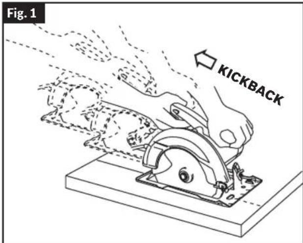
2. Kickback causes and related warnings
(Fig. 1)
- Kickback is a sudden reaction to a pinched, jammed or misaligned saw blade, causing an uncontrolled saw to lift up and out of the workpiece toward the operator.
- when the blade is pinched or jammed tightly by the kerf closing down, the blade stalls and the motor reaction drives the unit rapidly back toward the operator.
- If the blade becomes twisted or misaligned in the cut, the teeth at the back edge of the blade can dig into the top surface of the wood causing the blade to climb out of the kerf and jump back toward the operator.
Kickback is the result of saw misuse and/or incorrect operating procedures or conditions and can be avoided by taking proper precautions as given below.
Maintain a firm grip with both hands on the saw and position your arms to resist kickback forces. Position your body to either side of the blade, but not in line with the blade. Kickback could cause the saw to jump backwards, but kickback forces can be controlled by the operator, if proper precautions are taken.
When blade is binding, or when interrupting a cut for any reason, release the trigger and hold the saw motionless in the material until the blade comes to a complete stop. Never attempt to remove the saw from the work or pull the saw backward while the blade is in motion or kickback may occur. Investigate and take corrective actions to eliminate the cause of blade binding.
When restarting a saw in the workpiece, center the saw blade in the kerf so that the saw teeth are not engaged into the material. If a
SAVE THESE INSTRUCTIONS
Safety Warnings for Circular Saws
saw blade binds, it may walk up or kickback from the workpiece as the saw is restarted.
Support large panels to minimize the risk of blade pinching and kickback. Large panels tend to sag under their own weight. Supports must be placed under the panel on both sides, near the line of cut and near the edge of the panel.
Do not use dull or damaged blades. Unsharpened or improperly set blades produce narrow kerf causing excessive friction, blade binding and kickback.
Blade depth and bevel adjusting locking levers must be tight and secure before making the cut. If blade adjustment shifts while cutting, it may cause binding and kickback.
Use extra caution when sawing into existing walls or other blind areas. The protruding blade may cut objects that can cause kickback.
3. Lower guard function
Check the lower guard for proper closing before each use. Do not operate the saw if the lower guard does not move freely and close instantly. Never clamp or tie the lower guard into the open position. If the saw is accidentally dropped, the lower guard may be bent. Raise the lower guard with the retracting handle and make sure it moves freely and does not touch the blade or any other part, in all angles and depths of cut.
Check the operation of the lower guard spring. If the guard and the spring are not operating properly, they must be serviced before use. Lower guard may operate sluggishly due to damaged parts, gummy deposits, or a build-up of debris.
The lower guard may be retracted manually only for special cuts such as "plunge cuts" and "compound cuts". Raise the lower guard by the retracting handle and as soon as the blade enters the material, the lower guard must be released. For all other sawing, the lower guard should operate automatically.
Always observe that the lower guard is covering the blade before placing the saw down on bench or floor. An unprotected, coasting blade will cause the saw to walk backwards, cutting whatever is in its path. Be aware of the time it takes for the blade to stop after switch is released.
Additional Safety Warnings for Circular Saws
Inspect the condition and quality of the wood and remove all nails from lumber before cutting. Wet lumber, green lumber or pressure treated lumber require special attention during cutting operation to prevent kickback.
Hold the saw firmly to prevent loss of control. Figures in this manual illustrate typical hand support of the saw.
Depending upon use, the switch may not last the life of the saw. If the switch should fail in the "OFF" position, the saw may not start. If it should fail while the saw is running, the saw may not shut off. If either occurs, remove the battery pack from the saw immediately and do not use until repaired.
This circular saw should not be mounted to a table and converted to a table saw. Circular saws are not designed or intended to be used as table saws.
The blade washers and the bolt on your saw have been designed to work as a clutch to reduce the intensity of a kickback. Under-
Additional Safety Warnings for Circular Saws
stand the operation and settings of the VARI-TORQUE CLUTCH. The proper setting of the clutch, combined with firm handling of the saw will allow you to control kickback.
Never place your hand behind the saw blade. Kickback could cause the saw to jump backwards over your hand.
Do not use the saw with an excessive depth of cut setting. Too much blade exposure increases the likelihood of the blade twisting in the kerf and increases the surface area of the blade available for pinching that leads to kickback.
Do not run the tool while carrying it at your side. Lower guard may be opened by a contact with your clothing. Accidental contact with the spinning saw blade could result in serious personal injury.
Periodically remove the blade, clean the upper, lower guards and the hub area. Wipe it dry. Preventive maintenance and properly operating guard will reduce the probability of an accident.
Ensure the switch is in the off position before inserting battery pack. Inserting the battery pack into power tools that have the switch on invites accidents.
Avoid overheating saw blade tips.
Additional Safety Warnings
GFCI and personal protection devices like electrician's rubber gloves and footwear will further enhance your personal safety.
Develop a periodic maintenance schedule for your tool. When cleaning a tool be careful not to disassemble any portion of the tool since internal wires may be misplaced or pinched or safety guard return springs may be improperly mounted. Certain cleaning agents such as gasoline, carbon tetrachloride, ammonia, etc. may damage plastic parts.
WARNING Some dust created by power sanding, sawing, grinding, drilling, and other construction activities contains chemicals known to cause cancer, birth defects or other reproductive harm. Some examples of these chemicals are:
- Lead from lead-based paints,
- Crystalline silica from bricks and cement and other masonry products, and
- Arsenic and chromium from chemically-treated lumber.
Your risk from these exposures varies, depending on how often you do this type of work. To reduce your exposure to these chemicals: work in a well ventilated area, and work with approved safety equipment, such as those dust masks that are specially designed to filter out microscopic particles.
SAVE THESE INSTRUCTIONS
Intended Use
WARNING
Use this saw only as intended. Unintended use
may result in personal injury and property damage.
This circular saw is intended to cut wood and wood products.
This product is not intended to cut masonry, stone, tile, or metal. Dust build up around the lower guard and hub from other materials, such as plastic, masonry or metal, may disable the lower guard operation.
Cutting Masonry/Metal
WARNING
Do not cut metal or masonry with this circular saw.
The dust from metal or masonry cutting will cause the lower guard to become sluggish and
may not close fully and quickly after cutting these materials.
WARNING
Do not use abrasive wheels. This tool is not in-
tended for usage with metal or masonry cut-off wheels.
WARNING
Do not use Wet Diamond cutting off wheel or water
feed devices with this circular saw. Masonry cutting waste will enter the lower guard system, harden and cause the guard to become inoperable. Use of water in masonry cutting applications with an electric circular saw will cause electric shock hazards.
This tool is not intended for usage with metal or masonry cut-off wheels.
Symbols
Important: Some of the following symbols may be used on your tool. Please study them and learn their meaning. Proper interpretation of these symbols will allow you to operate the tool better and safer.
| Symbol Designation/Explanation | |
| V Volts (voltage) | |
| A Amperes (current) | |
| Hz Hertz (frequency, cycles per second) | |
| W Watt (power) | |
| kg Kilograms (weight) | |
| min Minutes (time) | |
| s Seconds (time) | |
| ∅ Diameter (size of drill bits, grinding wheels, etc.) | |
| n_0 | No load speed (rotational speed, at no load) |
| n Rated speed (Maximum attainable speed) | |
| rpm Revolutions per minute | |
| /min | Revolutions or reciprocation per minute (revolutions, strokes, surface speed, orbits etc. per minute) |
 | Arrow (action in the direction of arrow) |
| mm Millimeters (length) | |
| in Inches (length) | |
| --- | Direct current (type or a characteristic of current) |
 | Alerts user to read manual. |
 | Alerts user to wear eye protection. |
 | Alerts user to wear eye and respiratory protection. |
 | Alerts user to wear eye and hearing protection. |
 | Alerts user to wear eye, respiratory, and hearing protection.Alerts user to wear eye, respiratory, and hearing protection. |
Symbols
Important: Some of the following symbols may be used on your tool. Please study them and learn their meaning. Proper interpretation of these symbols will allow you to operate the tool better and safer.
| Symbol Designation/Explanation | |
 | This symbol designates that this tool is listed by the Canadian Standards Association, to United States and Canadian Standards. |
 Intertek Intertek | This symbol designates that this tool is listed by the Intertek Testing Services, to United States and Canadian Standards. |
 | Designates Li-ion battery recycling program. |
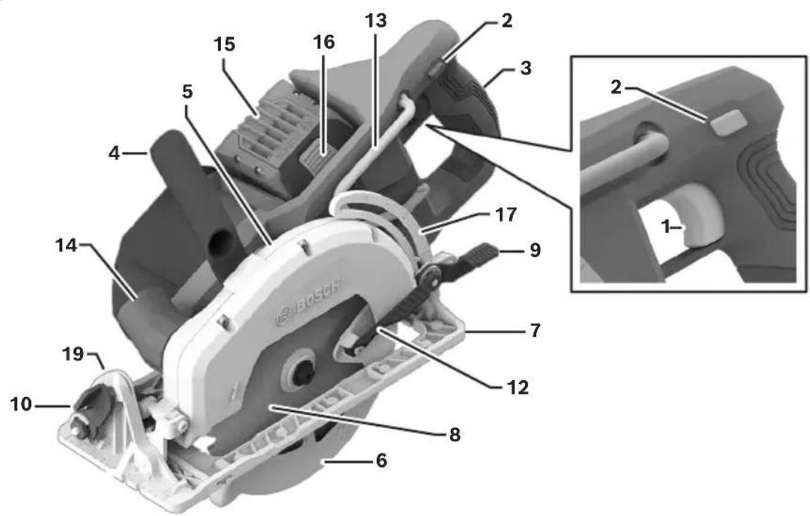
Getting to Know Your GKW18V-26 Cordless Circular Saw
Fig. 2
Getting to Know Your GKW18V-26 Cordless Circular Saw
Fig. 3
1 Trigger Switch
2 Lock-off Release Buttons
3 Control Handle (insulated gripping surface)
4 Auxiliary Handle (insulated gripping surface)
5 Upper Guard
6 Lower Guard
7 Foot
8 Blade
9 Depth Adjustment Lever
10 Bevel Adjustment Lever
11 Shaft Lock Button
12 Lower Guard Lift Lever (retracting handle)
13 Saw Hook
14 Dust Port
15 Battery Pack*
16 Battery Pack Release Button
17 Cutting Depth Scale
18 Rip Fence Wing Bolt
19 Bevel Scale
Specifications
| Model number GKW18V-26 | |
| Voltage rating 18V | |
| No load speed 5,000 rpm | |
| Blade* 7-1/4" | |
| Blade arbor hole 5/8" (16 mm) Round | |
| Blade tooth thickness | 1/16" (1.6 mm)minimum 3/64" (1.0 mm) |
| Blade body thickness 0.079" (2.0 mm) Maximum | |
| Depth of cut at 0° 2-5/8" (66 mm) Maximum | |
| Depth of cut at 45° 1-13/16" (46 mm) Maximum | |
| Depth of cut at 53° 1-1/2" (38 mm) Maximum | |
| Permitted battery temperature during charging | +32...+113°F (0...+45°C) |
| Permitted ambient temperature during operation and storage | -4...+122°F (-20...+50°C) |
| Recommended ambient temperature during charging | +32...+95°F (0...+35°C) |
* For replacement blades we recommend Bosch Cordless Circular saw blades. Their thin kerf and tooth design deliver the superior speed, quality of cut, and reduce battery drain. Use of standard blades will substantially affect the performance and reduce run-time.
Battery Packs/Chargers
Please refer to the battery/charger list, included with your tool.
Assembly
WARNING Disconnect battery pack from tool before making any assembly, adjustments or changing accessories. Such preventive safety measures reduce the risk of starting the tool accidentally.
Attaching the Blade
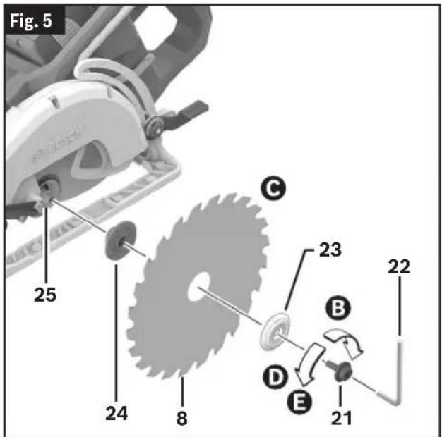
(Fig. 2, Fig. 4, Fig. 5, Fig. 6)
WARNING Use only 7-1/4" blade. Use only blade rated 5000 rpm
or greater. Using blade not designed for the saw may result in serious personal injury and property damage.
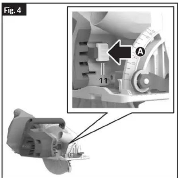
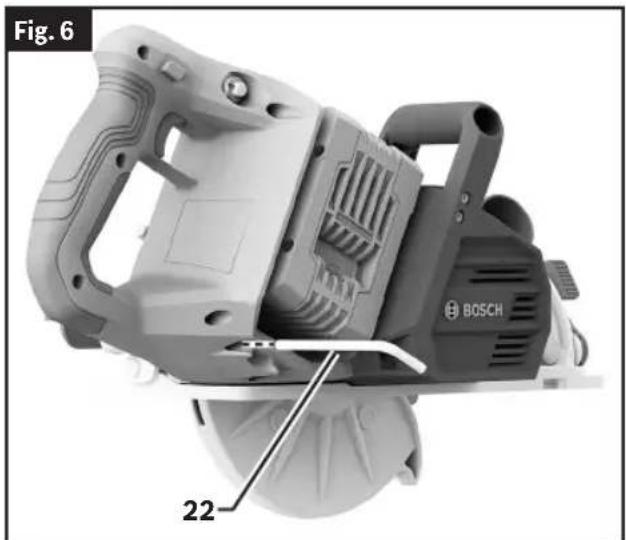
- Press and hold the Shaft Lock Button 11 A Turn Blade Stud 21 with provided Wrench 22 clockwise Band remove Blade Stud 21 and Outer Washer 23.
Note: The Wrench 22 is stored near the battery compartment. - Make sure the saw teeth and arrow on the Blade 8 point in the same direction as the arrow on the Lower Guard 6.
- Retract the Lower Guard 6 all the way up into the Upper Guard 5. While retracting the Lower Guard 6, check operation and condition of the lower guard spring.
-
Slide Blade 8 through slot in the Foot 7 and mount it against the Inner Washer 24 on the Shaft 25. Be sure the large diameter of the Outer Washer 23 lays flush against the Blade 8 ©
-
Reinstall Outer Washer 23 and tighten Blade Stud 21 finger tight counterclockwise D. Press and hold the Shaft Lock Button 11 and tighten the Blade Stud 21 counterclockwise 1/4 turn with the Wrench 22E
Do not use wrenches with longer handles, since it may lead to over tightening of the Blade Stud 21.
natural_image
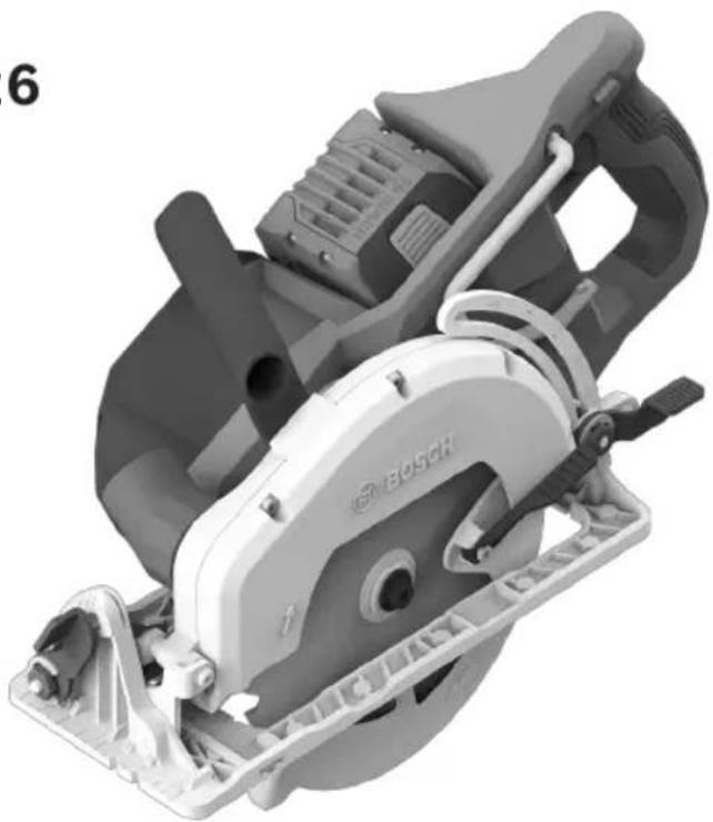
Mechanical power saw with Bosch branding, labeled as Figure 6 (no text or symbols on the device itself)Assembly
Vari-Torque Clutch
(Fig. 5)
This clutching action is provided by the friction of the Outer Washer 23 against the Blade 8 and permits the blade shaft to turn when the blade encounters excessive resistance. When the Blade Stud 21 is properly tightened (as described in "Attaching the Blade," step 5), the Blade 8 will slip when it encounters excessive resistance, thus reducing saw's tendency to kickback.
One setting may not be sufficient for cutting all materials. If excessive blade slippage occurs, tighten the Blade Stud 21 a fraction of a turn more (less than 1/8 turn). Overtightening the Blade Stud 21 nullifies the effectiveness of the clutch.
Dust Extraction
WARNING To reduce the risk of injury, always position dust port and vacuum hose so that they do not interfere with the lower guard, or the cutting operation at all settings.
WARNING Be extremely careful when disposing of dust. Materials in fine particle form may be explosive. Do not throw sawdust on an open fire. Spontaneous combustion, in time, may result from the mixture of oil or water with dust particles.
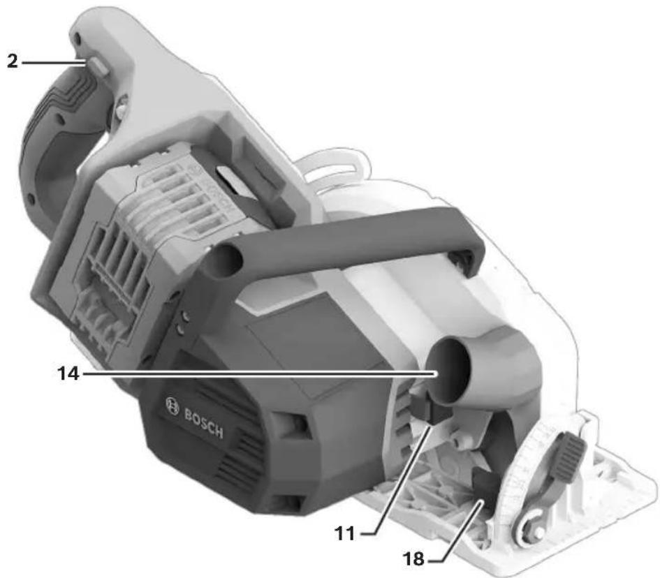
Dust Port
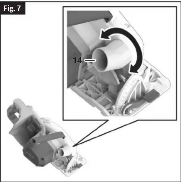
(Fig. 7)
The Dust Port 14 swivels so that dust can be directed in the desired direction.
Assembly
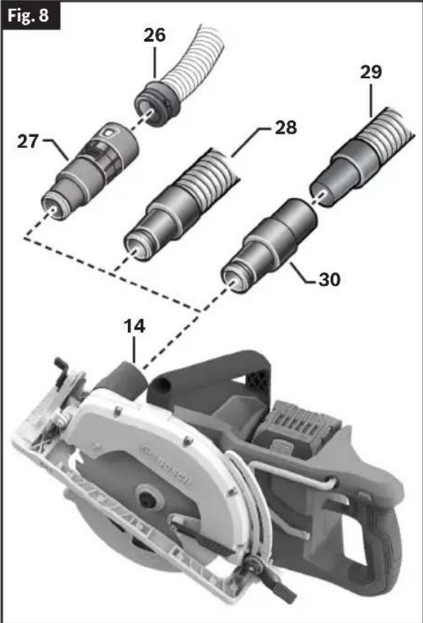
Connection to Vacuum / Dust Extractor
(Fig. 8)
Connect the vacuum hose to the Dust Port 14.
- Bosch VH-Series Hoses 26 - The VX120 Hose Adapter 27 is required (included with VH-series hoses).
- Other 35mm and 22mm hoses, such as the Bosch VAC-Series Hoses 28 - Connect hose directly to the tool.
- Common 1-1/4" or 1-1/2" Hoses 29 - The Bosch VAC024 Adapter 30 is required (sold separately).
Connect the vacuum hose to a vacuum.
The vacuum must be suitable for the material being worked on.
When vacuuming dry dust that is especially detrimental to health or carcinogenic, use a special vacuum / dust extractor.
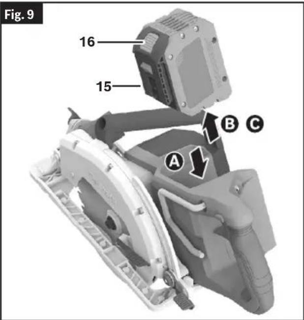
Inserting and Releasing Battery Pack
(Fig. 9)
WARNING Use only Bosch or AMP-Share batteries recommended in the battery/charger list, included with your tool. Using other types of batteries may result in personal injury or property damage.
Slide charged Battery Pack 15 into the housing until the Battery Pack 15 locks into position A
Your tool is equipped with a secondary locking latch to prevent the Battery Pack 15 from completely falling out of the tool should it become loose due to vibration.
To remove the Battery Pack 15, press the Battery Pack Release Button 16 and slide the Battery Pack 15 up Ⓗ
Press the Battery Pack Release Button 16 again and slide the battery pack completely out of tool housing ©
Operating Instructions
WARNING Disconnect battery pack from tool before making any assembly, adjustments or changing accessories. Such preventive safety measures reduce the risk of starting the tool accidentally.
Brake Action
WARNING Let the saw blade come to a complete stop before setting the tool down. The brake action of this circular saw is not intended as a safety feature. Unintended contact with a rotating saw blade can cause property damage and/or personal injury.
WARNING Know the charge state of your battery. The electric braking action is initiated ONLY by the release of the trigger switch and in a tool that has power available. When electrical power is lost due to a discharged battery or other causes, the electric brake will not operate and the motor will gradually slow down. Unexpected run down time may cause property damage and/or personal injury.
Your circular saw is equipped with an automatic electric brake, which is designed to stop the saw blade from spinning in approximately two (2) seconds after you release the trigger switch. This feature helps improve jobsite productivity.
Braking starts once the power is turned off. The brake requires a charged battery to function.
Stopping time will vary depending on, among other factors, saw blade used, and number of actuations. The electric brake of your circular saw has been designed for a high degree of reliability, but unexpected circumstances such as contamination or failure of the motor's components can cause the brake to not activate. If the tool operates but the brake does not consistently stop the blade in about 2 seconds, DO NOT use the circular saw and have it serviced by a Bosch Factory Service Center or Bosch authorized service facility.
Protection Against Deep Discharging
The lithium ion battery is protected against deep discharging by the “Electronic Cell Protection (ECP).” When the battery is empty, the tool is switched off by means of a protective circuit.
Overload Protection
Your saw is equipped with Electronic Motor Protection (EMP), which shuts the tool off under overload conditions that could damage the tool. This feature can be reset by simply releasing the trigger and re-engaging the trigger again to restart the tool.
Depth Adjustment
(Fig. 2, Fig. 10)
⚠ WARNING Adjust the cutting depth so that no more than one tooth is visible below the work piece. Excessive blade exposure below the workpiece could result in personal injury and/or property damage.
WARNING The depth adjustment system should be not used to change the depth while the saw is in operation, or for plunge cutting. If blade adjustment shifts while cutting, it may cause binding and kickback.
To adjust the cutting depth follow these instructions:
- Disconnect Battery Pack 15 from tool.
- Loosen the Depth Adjustment Lever 9 located on the left side of the tool.
- Hold the Foot 7 down with one hand and raise or lower saw by the Control Handle 3.
- For a smaller cutting depth, pull the saw away from the Foot 7;
-
For a deeper cutting depth, push the saw toward the Foot 7. The Cutting Depth Scale 17 has an inch scale.
-
Tighten the Depth Adjustment Lever 9 at the desired depth setting.
Note: Not more than one tooth length of the Blade 8 should extend below the material to be cut, for minimum splintering ^A
Operating Instructions
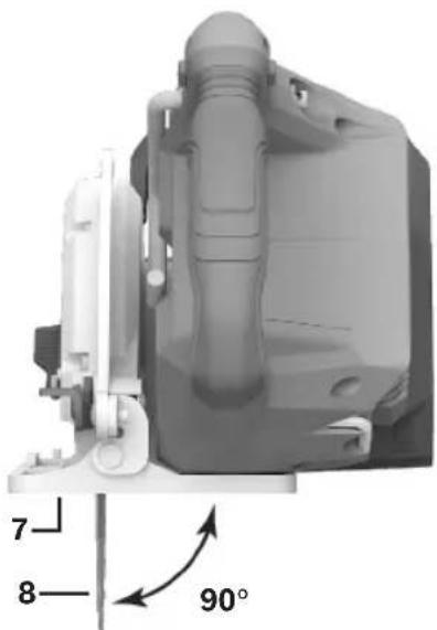
90° Cutting Angle Check
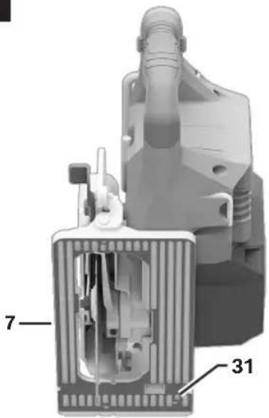
(Fig. 2, Fig. 10, Fig. 11, Fig. 12)
- Disconnect Battery Pack 15 from tool.
- Set Foot 7 to maximum depth of cut setting.
- Loosen the Bevel Adjustment Lever 10, set to 0° on Bevel Scale 19, retighten the Bevel Adjustment Lever 10.
- Check for 90° angle between the Blade 8 and bottom plane of Foot 7 with a square. If necessary, make adjustments by turning the small Alignment Screw 31 on the bottom of the Foot 7 with a 2.5 mm allen wrench (not included).
Fig. 11
natural_image
3D mechanical component diagram showing internal structure with angular measurement (90°) and numbered parts (7, 8), no readable text or symbols beyond labels.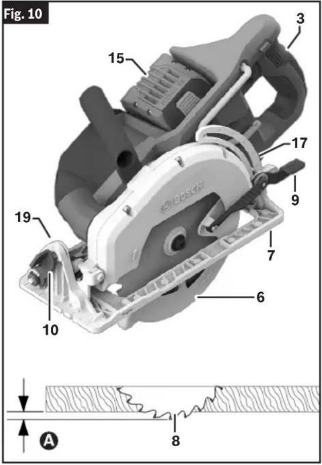
Fig. 12
Operating Instructions
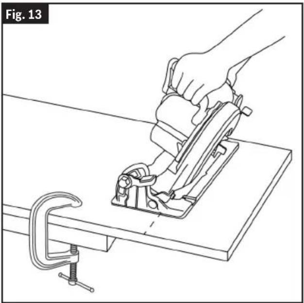
Bevel Adjustment
(Fig. 10, Fig. 13)
- Disconnect Battery Pack 15 from tool.
- Loosen the Bevel Adjustment Lever 10.
- Align to desired angle on the Bevel Scale 19. The foot can be adjusted up to 53°.
- Tighten Bevel Adjustment Lever 10.
Because of the increased amount of blade engagement in the work and decreased stability of the foot, blade binding may occur. Keep the saw steady and the foot firmly on the workpiece.
natural_image
Line drawing of a hand using a lathe machine to cut a metal component, with a clamp bracket nearby (no text or symbols)Cutting Line Guide Notches
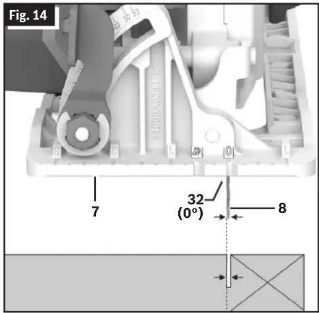
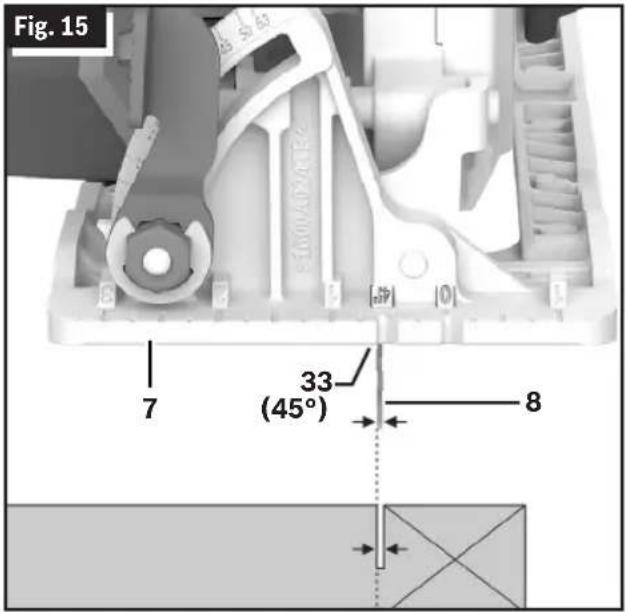
(Fig. 14, Fig. 15)
The 0° Cutting Line Guide Notch 32 and the 45° Cutting Line Guide Notch 33 at the front of the Foot 7 indicate the approximate line of the cut.
- For a non-bevelled cut, use the 0° Cutting Line Guide Notch 32.
- For 45° and 50° bevel cuts, use the 45° Cutting Line Guide Notch 33.
- Make sample cuts in scrap lumber to verify actual line of cut. This will be helpful because of the variety of blade types and thicknesses that are available.
- Use RIGHT side of notch when the part of the workpiece that is to the left of the Blade 8 is the scrap piece.
- Use LEFT side of notch when the part of the workpiece that is to the right of the Blade 8 is the scrap piece.
Operating Instructions
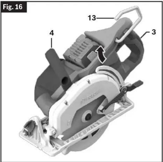
Saw Hook
(Fig. 16)
WARNING To reduce the risk of injury, do not use the saw hook
if it appears damaged or deformed. This could result in unstable hanging and the tool unexpectedly falling.
To reduce the risk of injury, use care in selecting the location for hanging the tool.
- Select a suitably sized and shaped object that will provide adequate hanging stability. An unsuitable hanging surface could result in the tool unexpectedly falling.
- Make sure that the tool is hung out of the way of walkways and working areas with bystanders. The tool could be bumped or a bystander could become entangled, causing the tool to unexpectedly fall.
To use the Saw Hook 13, simply lift up the Saw Hook 13 180° until it snaps into the open position. When not in use, always close the Saw Hook 13 until it snaps into the closed position.
Lock-off Release Buttons
(Fig. 2)
The Lock-off Release Buttons 2 are designed to prevent accidental starts. To operate, press the Lock-off Release Button 2 with your thumb on either side of handle to disengage the lock, then pull the Trigger Switch 1. When the Trigger Switch 1 is released, the Lock-off Release Button 2 will engage the Trigger Switch 1 automatically, and the Trigger Switch 1 will no longer operate.
Switch
(Fig. 2)
WARNING When starting the tool, hold it with both hands.
The torque from the motor may cause the tool to twist.
To turn tool ON, press the Lock-off Release Button 2 with your thumb on either side of handle to disengage the lock, then pull the Trigger Switch 1.
To turn the tool OFF, release the Trigger Switch 1, which is spring loaded and will return to the off position automatically.
Your saw should be running at full speed BEFORE starting the cut, and turned off only AFTER completing the cut. To increase switch life, do not turn switch on and off while cutting.
Operating Instructions
All Cuts
(Fig. 2, Fig. 16, Fig. 17)

Always be sure either hand does not interfere with the the lower guard.
free movement of

After completing a cut and the trigger has been released, be aware of the necessary time it takes for the blade to come to a complete stop during coast down. Do not allow the saw to brush against your leg or side, since the lower guard is retractable, it could catch on your clothing and expose the blade. Be aware of the necessary blade exposures that exist in both the upper and lower guard areas.
Always hold the Control Handle 3 with one hand and the Auxiliary Handle 4 with the other.
Always make sure the Motor 34 side of the saw Foot 7 rests on the supported portion of the Workpiece 35.
Maintain a firm grip and operate the Trigger Switch 1 with a decisive action. Never force the saw. Use light and continuous pressure.
When cutting is interrupted, to resume cutting. squeeze the Trigger Switch 1 and allow the Blade 8 to reach full speed, re-enter the cut slowly and resume cutting.
Do not cut stacked materials. Cut one piece at a time.
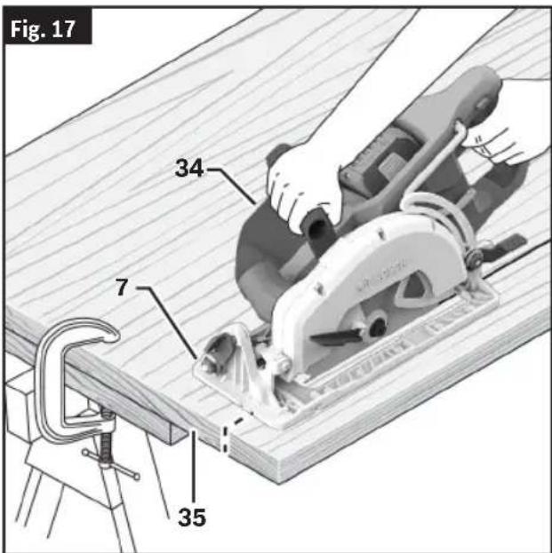
20
When cutting across the grain, the fibers of the wood have a tendency to tear and lift. Advancing the saw slowly minimizes this effect. To ensure minimum splintering on the good side of the material to be cut, face the good side down. For a finished cut, a cross cut blade or miter blade is recommended.
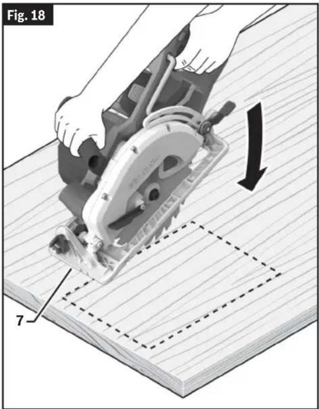
Plunge Cuts
(Fig. 2, Fig. 14, Fig. 15, Fig. 18)

Adjust the cutting depth to the thickness of the work-
piece. Less than a full tooth of the blade teeth should be visible below the workpiece.

As blade starts cutting the material, release the lower
guard immediately. When the foot rests flat on the surface being cut, proceed cutting in forward direction to end of cut.

Allow blade to come to a complete stop before lift-
ing the saw from cut. Never pull the saw backward. Pulling the saw backwards may cause the blade to climb out of the material and cause KICKBACK.
- Disconnect the Battery Pack 15 from the tool before making adjustments.
- Set the Depth Adjustment Lever 9 according to the material to be cut.
-
Reattach the Battery Pack 15 to the saw.
-
Tilt the saw forward with the 0° Cutting Line Guide Notch 32 or the 45° Cutting Line Guide Notch 33 lined up with the line that is drawn.
-
Raise the Lower Guard 6 using the Lower Guard Lift Lever 12 and hold the saw by the Control Handle 3.
-
With the Blade 8 just clearing the material to be cut, start the motor by pulling the Trigger Switch 1 with the Lock-Off Release Button 2 engaged.
-
Gradually lower the back end of the saw using the front end of the Foot 7 as the hinge point.
-
Release the Lower Guard Lift Lever 12 immediately when the blade starts cutting the material.

Operating Instructions
-
Once the saw has been lowered fully into the material and the base plate is flat on the the workpiece, proceed cutting in the forward direction. Do not cut backwards.
-
To complete the cut, turn OFF the saw and allow the blade to come to a complete stop. Then turn the saw around and finish the cut in the normal manner, sawing forward. If corners of your pocket cut are not completely cut through, use a jigsaw or hand saw to finish the corners.
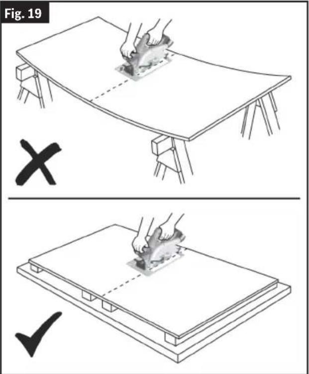
Cutting Large Sheets
(Fig. 19)
Large sheets and long boards sag or bend, depending on support. If you attempt to cut without leveling and properly supporting the piece, the blade will tend to bind, causing KICKBACK and extra load on the motor.
Support the panel or board close to the cut. Be sure to set the depth of the cut so that you cut through the sheet or board only and not the table or work bench. The two-by-fours used to raise and support the work should be positioned so that the broadest sides support the work and rest on the table or bench. Do not support the work with the narrow sides as this is an unsteady arrangement. If the sheet or board to be cut is too large for a table or work bench, use the supporting two-by-fours on the floor and secure.
Operating Instructions
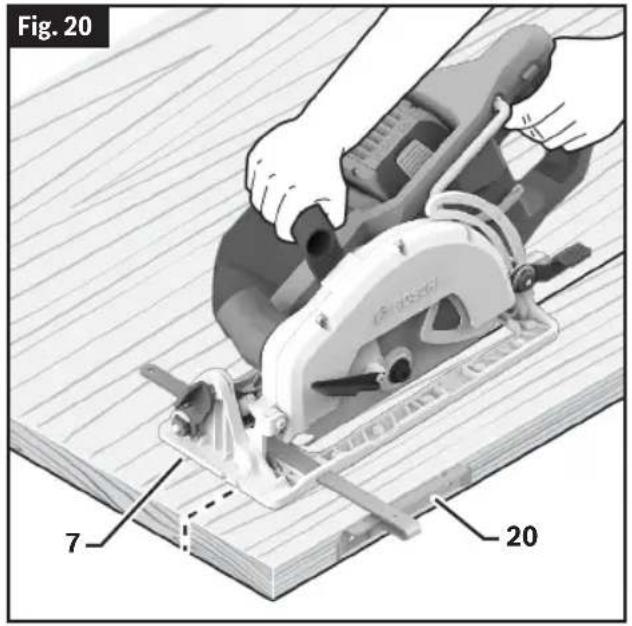
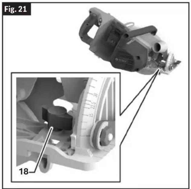
Rip Cuts
(Fig. 20, Fig. 21)
WARNING
After attaching or adjusting the rip fence, be sure the rip fence does not touch or interfere with the free movement of the lower guard or contact the saw blade.
The combination blade provided with your saw is for both cross cuts and rip cuts. Ripping is cutting lengthwise with the grain of the wood. Narrow rip cuts are easy to do with the Rip Fence 20. To attach the optional Rip Fence 20, insert the fence through the slots in the Foot 7 to the desired width, and secure it with the Rip Fence Wing Bolt 18.
natural_image
Technical illustration of a cutting tool with magnified inset showing measurement scale (no text or symbols)Maintenance
WARNING
To avoid accidents, always disconnect battery pack from tool before cleaning or performing any maintenance.
Service
WARNING
NO USER SERVICE-ABLE PARTS INSIDE. Preventive maintenance performed by unauthorized personnel may result in misplacing of internal wires and components which could cause serious hazard. We recommend that all tool service be performed by a Bosch Factory Service Center or Authorized Bosch Service Station.
Batteries
Be alert for battery packs that are nearing their end of life. If you notice decreased tool performance or significantly shorter running time between charges then it is time to replace the battery pack. Failure to do so can cause the tool to operate improperly or damage the charger.
Tool Lubrication
Your Bosch tool has been properly lubricated and is ready for use.
Motors
The motor in your tool has been engineered for many hours of dependable service. To maintain peak efficiency of the motor, we recommend it be examined every six months. Only a genuine Bosch replacement motor specially designed for your tool should be used.
Bearings
Bearings which become noisy (due to heavy load or very abrasive material cutting) should be replaced at once to avoid overheating and motor failure.
Cleaning
CAUTION
Certain cleaning agents and solvents damage plastic
parts. Some of these are: gasoline, carbon tetrachloride, chlorinated cleaning solvents, ammonia and household detergents that contain ammonia.
Ventilation openings and switch levers must be kept clean and free of foreign matter. Do not
attempt to clean by inserting pointed objects through opening.
Develop a periodic maintenance schedule for your tool. When cleaning a tool be careful not to disassemble any portion of the tool since internal wires may be misplaced or pinched or safety guard return springs may be improperly mounted. Certain cleaning agents such as gasoline, carbon tetrachloride, ammonia, etc. may damage plastic parts.
Care of Blades
Blades become dull even from cutting regular lumber. If you find yourself forcing the saw forward to cut instead of just guiding it through the cut, chances are the blade is dull or coated with wood pitch.
When cleaning gum and wood pitch from blade, remove the battery from the saw and remove the blade. Remember, blades are designed to cut, so handle carefully. Wipe the blade with kerosene or similar solvent to remove the gum and pitch. Unless you are experienced in sharpening blades, we recommend you do not try.
Accessories and Attachments
WARNING
The use of any other attachments or accessories not specified in this manual may create a hazard.
Store accessories in a dry and temperate environment to avoid corrosion and deterioration.
| Bosch No. Description | Included | Sold Separately | |
| GKSLPG Rip fence - ● | |||
| Various Vacuum Hoses | - ● | ||
| VAC024 | Vacuum Hose Adapter for 1-1/4" and 1-1/2" Hoses | - ● |
natural_image
Close-up of a Bosch electric shaver with labeled component (22), no visible text or symbols beyond label and part numberMontage de la scie
Embrayage Vari-Torque
(Fig. 5)
natural_image
Mechanical assembly diagram showing a component with a numbered arrow and magnified view of internal components (no text or symbols)Montage de la scie
natural_image
Line drawing of a hand using a lathe machine to lift a workpiece, with a clamp bracket nearby (no text or symbols)Bearings which become noisy (due to heavy load or very abrasive material cutting) should be replaced at once to avoid overheating and motor failure.
Nettoyage
natural_image
Mechanical power saw with Bosch branding, labeled as Figure 6 (no text or symbols on the device itself)natural_image
Line drawing of a hand using a lathe machine to cut a workpiece, with a clamp bracket nearby (no text or symbols)Copyright © 2009-2020 ARM LIMITED
All rights reserved.
Redistribution and use in source and binary forms, with or without modification, are permitted provided that the following conditions are met:
— Redistributions of source code must retain the above copyright notice, this list of conditions and the following disclaimer.
— Redistributions in binary form must reproduce the above copyright notice, this list of conditions and the following disclaimer in the do-cumentation and/or other materials provided with the distribution.
— Neither the name of ARM nor the names of its contributors may be used to endorse or promote products derived from this software without specific prior written permission.
THIS SOFTWARE IS PROVIDED BY THE COPYRIGHT HOLDERS ANDCONTRIBUTORS "AS IS" AND ANY EXPRESS OR IMPLIED WARRANTIES,INCLUDING, BUT NOT LIMITED TO, THE IMPLIED WARRANTIES OFMERCHANTABILITY AND FITNESS FOR A PARTICULAR PURPOSE AREDISCLAIMED. IN NO EVENT SHALL THE COPYRIGHT OWNER ORCONTRIBUTORS BE LIABLE FOR ANY DIRECT, INDIRECT, INCIDENTAL,SPECIAL, EXEMPLARY, OR CONSEQUENTIAL DAMAGES (INCLUDING,BUT NOT LIMITED TO, PROCUREMENT OF SUBSTITUTE GOODS ORSERVICES; LOSS OF USE, DATA, OR PROFITS; OR BUSINESSINTERRUPTION) HOWEVER CAUSED AND ON ANY THEORY OF LIABILITY, WHETHER IN CONTRACT, STRICT LIABILITY, OR TORT(INCLUDING NEGLIGENCE OR OTHERWISE) ARISING IN ANY WAY OUTOF THE USE OF THIS SOFTWARE, EVEN IF ADVISED OF THE POSSIBILITY OF SUCH DAMAGE.
Copyright © 2012-2020 STMicroelectronics
All rights reserved.
Redistribution and use in source and binary forms, with or without modification, are permitted provided that the following conditions are met:
— Redistributions of source code must retain the above copyright notice, this list of conditions and the following disclaimer.
— Redistributions in binary form must reproduce the above copyright notice, this list of conditions and the following disclaimer in the do-cumentation and/or other materials provided with the distribution.
— Neither the name of STMicroelectronics nor the names of its contributors may be used to endorse or promote products derived from this
software without specific prior written permission.
THIS SOFTWARE IS PROVIDED BY THE COPYRIGHT HOLDERS ANDCONTRIBUTORS "AS IS" AND ANY EXPRESS OR IMPLIED WARRANTIES,INCLUDING, BUT NOT LIMITED TO, THE IMPLIED WARRANTIES OFMERCHANTABILITY AND FITNESS FOR A PARTICULAR PURPOSE AREDISCLAIMED. IN NO EVENT SHALL THE COPYRIGHT OWNER ORCONTRIBUTORS BE LIABLE FOR ANY DIRECT, INDIRECT, INCIDENTAL,SPECIAL, EXEMPLARY, OR CONSEQUENTIAL DAMAGES (INCLUDING,BUT NOT LIMITED TO, PROCUREMENT OF SUBSTITUTE GOODS ORSERVICES; LOSS OF USE, DATA, OR PROFITS; OR BUSINESSINTERRUPTION) HOWEVER CAUSED AND ON ANY THEORY OFLIABILITY, WHETHER IN CONTRACT, STRICT LIABILITY, OR TORT(INCLUDING NEGLIGENCE OR OTHERWISE) ARISING IN ANY WAY OUTOF THE USE OF THIS SOFTWARE, EVEN IF ADVISED OF THEPOSSIBILITY OF SUCH DAMAGE.
Warranty Disclaimer
This product contains Open Source Software components which underly Open Source Software Licenses. Please note that Open Source
Licenses contain disclaimer clauses. The text of the Open SourceLicenses that apply are included in this manual under "Licenses".
LIMITED WARRANTY
For details on the terms of the limited warranty for this product, go to https://rb-pt.io/PowerToolWarranty or call 1-877-BOSCH99.
GARANTIE LIMITÉE
© Robert Bosch Tool Corporation
1800 W. Central Road
Mt. Prospect, IL 60056-2230
1605A002FN 07/2024