
GCM 12 MX Professional - Saw BOSCH - Free user manual and instructions
Find the device manual for free GCM 12 MX Professional BOSCH in PDF.

| Product Type | Mitre Saw |
| Model Number | GCM 12 MX Professional |
| Rated Power Input | 1800 W |
| No-Load Speed | 4300 min⁻¹ |
| Weight (EPTA 01:2014) | 20.7 kg |
| Saw Blade Diameter | 305 mm |
| Blade Body Thickness | 1.7 – 2.62 mm |
| Mounting Hole Diameter | 25.4 mm |
| Max. Cutting Depth (0°/0°) | 75 mm (fence), 100 mm (distance stop) |
| Max. Workpiece Dimensions (0°/0°) | 75 x 200 mm (fence), 100 x 150 mm (distance stop) |
| Mitre Angle Range | -52° to +52° |
| Bevel Angle Range | -2° to +47° |
| Protection Class | II (Double insulated) |
| Dust Extraction | Integrated dust bag and external vacuum adapter |
| Retracting Blade Guard | Yes |
| Spindle Lock | Yes (for blade changes) |
| Transport Safety Lock | Yes |
| Saw Table Extensions | Left and right, adjustable |
| Material Clamp | Included |
| On/Off Switch | Non-locking, push-to-run |
Frequently Asked Questions - GCM 12 MX Professional BOSCH
User questions about GCM 12 MX Professional BOSCH
0 question about this device. Answer the ones you know or ask your own.
Ask a new question about this device
Download the instructions for your Saw in PDF format for free! Find your manual GCM 12 MX Professional - BOSCH and take your electronic device back in hand. On this page are published all the documents necessary for the use of your device. GCM 12 MX Professional by BOSCH.
USER MANUAL GCM 12 MX Professional BOSCH
OBJ_BUCH-3086-001.book. Page 1 Thursday, December 22, 2016 2:33 PM
natural_image
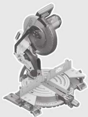
Mechanical cutting machine with a blade and circular base (no visible text or symbols)Robert Bosch Power Tools GmbH
70538 Stuttgart
GERMANY
www.bosch-pt.com
1609 92A 2HL (2016.12) PS / 88

GCM 12 MX Professional

BOSCH
natural_image
Exploded view diagram of a Bosch cutting machine assembly (no text or symbols on the diagram itself)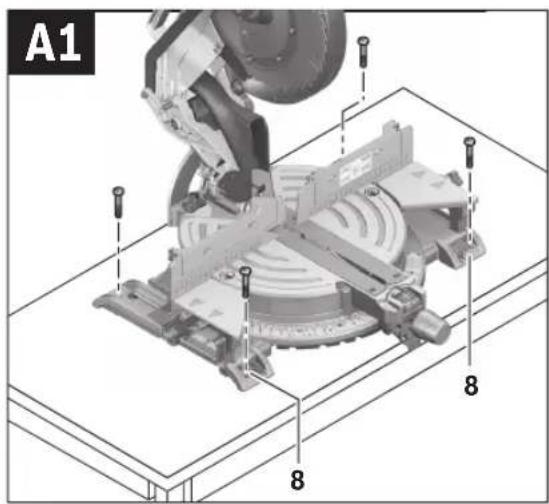
natural_image
Mechanical assembly diagram showing a cutting machine with a bracket and mounting base, no visible text or symbols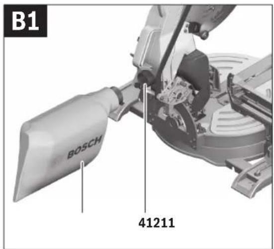
8
natural_image
Mechanical component diagram showing a motor handle and lever mechanism (no text or symbols)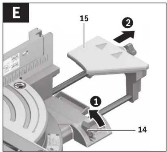
Bosch Power Tools 1 609 92A 2HL | (22.12.16)
10
natural_image
Mechanical assembly diagram showing a gear and brake system (no text or symbols visible)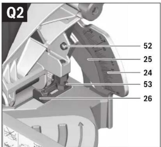
natural_image
Mechanical assembly diagram showing a cutting machine with rotating components and a labeled section R1 (no readable text or symbols)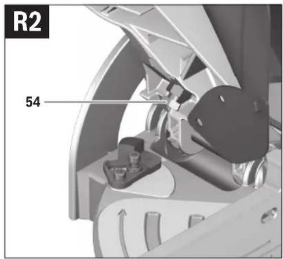
natural_image
Mechanical assembly diagram showing a motor and gear assembly (no text or symbols visible)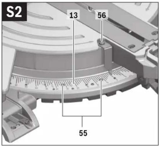
Bosch Power Tools 1 609 92A 2HL | (22.12.16)
12 | English
English
Safety Notes
General Power Tool Safety Warnings
WARNING
When using electric tools basic safety precautions should always be followed to reduce the risk of fire, electric shock and personal injury including the following.
Read all these instructions before attempting to operate this product and save these instructions.
The term "power tool" in the warnings refers to your mains-operated (corded) power tool or battery-operated (cordless) power tool.
Work area safety
- Keep work area clean and well lit. Cluttered or dark areas invite accidents.
Do not operate power tools in explosive atmospheres, such as in the presence of flammable liquids, gases or dust. Power tools create sparks which may ignite the dust or fumes.
▶ Keep children and bystanders away while operating a power tool. Distractions can cause you to lose control.
Electrical safety
▶ Power tool plugs must match the outlet. Never modify the plug in any way. Do not use any adapter plugs with earthed (grounded) power tools. Unmodified plugs and matching outlets will reduce risk of electric shock.
▶ Avoid body contact with earthed or grounded surfaces, such as pipes, radiators, ranges and refrigerators. There is an increased risk of electric shock if your body is earthed or grounded.
▶ Do not expose power tools to rain or wet conditions. Water entering a power tool will increase the risk of electric shock.
▶ Do not abuse the cord. Never use the cord for carrying, pulling or unplugging the power tool. Keep cord away from heat, oil, sharp edges and moving parts. Damaged or entangled cords increase the risk of electric shock.
When operating a power tool outdoors, use an extension cord suitable for outdoor use. Use of a cord suitable for outdoor use reduces the risk of electric shock.
If operating a power tool in a damp location is unavoidable, use a residual current device (RCD) protected supply. Use of an RCD reduces the risk of electric shock.
Personal safety
▶ Stay alert, watch what you are doing and use common sense when operating a power tool. Do not use a power tool while you are tired or under the influence of drugs, alcohol or medication. A moment of inattention while operating power tools may result in serious personal injury.
▶ Use personal protective equipment. Always wear eye protection. Protective equipment such as dust mask, non-skid safety shoes, hard hat, or hearing protection
used for appropriate conditions will reduce personal injuries.
▶ Prevent unintentional starting. Ensure the switch is in the off-position before connecting to power source and/or battery pack, picking up or carrying the tool.
Carrying power tools with your finger on the switch or energising power tools that have the switch on invites accidents.
Remove any adjusting key or wrench before turning the power tool on. A wrench or a key left attached to a rotating part of the power tool may result in personal injury.
▶ Do not overreach. Keep proper footing and balance at all times. This enables better control of the power tool in unexpected situations.
▶ Dress properly. Do not wear loose clothing or jewellery. Keep your hair, clothing and gloves away from moving parts. Loose clothes, jewellery or long hair can be caught in moving parts.
If devices are provided for the connection of dust extraction and collection facilities, ensure these are connected and properly used. Use of dust collection can reduce dust-related hazards.
Power tool use and care
▶ Do not force the power tool. Use the correct power tool for your application. The correct power tool will do the job better and safer at the rate for which it was designed.
▶ Do not use the power tool if the switch does not turn it on and off. Any power tool that cannot be controlled with the switch is dangerous and must be repaired.
▶ Disconnect the plug from the power source and/or the battery pack from the power tool before making any adjustments, changing accessories, or storing power tools. Such preventive safety measures reduce the risk of starting the power tool accidentally.
▶ Store idle power tools out of the reach of children and do not allow persons unfamiliar with the power tool or these instructions to operate the power tool. Power tools are dangerous in the hands of untrained users.
- Maintain power tools. Check for misalignment or binding of moving parts, breakage of parts and any other condition that may affect the power tool's operation. If damaged, have the power tool repaired before use. Many accidents are caused by poorly maintained power tools.
▶ Keep cutting tools sharp and clean. Properly maintained cutting tools with sharp cutting edges are less likely to bind and are easier to control.
▶ Use the power tool, accessories and tool bits etc. in accordance with these instructions, taking into account the working conditions and the work to be performed. Use of the power tool for operations different from those intended could result in a hazardous situation.
Service
▶ Have your power tool serviced by a qualified repair person using only identical replacement parts. This will ensure that the safety of the power tool is maintained.
English | 13
Safety Warnings for Mitre Saws
▶ Never stand on the power tool. Serious injuries can occur when the power tool tips over or when inadvertently coming into contact with the saw blade.
▶ Make sure that the guard operates properly and that it can move freely. Never lock the guard in place when opened.
▶ Never remove cutting remainders, wood chips, etc. from the sawing area while the machine is running. Always guide the tool arm back to the neutral position first and then switch the machine off.
▶ Guide the saw blade against the workpiece only when the machine is switched on. Otherwise there is danger of kickback when the saw blade becomes wedged in the workpiece.
▶ Keep handles dry, clean, and free from oil and grease. Greasy, oily handles are slippery causing loss of control.
▶ Operate the power tool only when the work area to the workpiece is clear of any adjusting tools, wood chips, etc. Small pieces of wood or other objects that come in contact with the rotating saw blade can strike the operator with high speed.
- Keep the floor free of wood chips and material remainders. You could slip or trip.
▶ Always firmly clamp the piece to be worked. Do not saw workpieces that are too small to clamp. Otherwise, the clearance of your hand to the rotating saw blade is too small.
▶ Use the machine only for cutting the materials listed under Intended Use. Otherwise, the machine can be subject to overload.
If the saw blade should become jammed, switch the machine off and hold the workpiece until the saw blade comes to a complete stop. To prevent kickback, the workpiece may not be moved until after the machine has come to a complete stop. Correct the cause for the jamming of the saw blade before restarting the machine.
▶ Do not use dull, cracked, bent or damaged saw blades. Unsharpened or improperly set saw blades produce narrow kerf causing excessive friction, blade binding and kick-back.
▶ Always use blades with correct size and shape (diamond versus round) of arbour holes. Blades that do not match the mounting hardware of the saw will run eccentrically, causing loss of control.
▶ Do not use high speed steel (HSS) saw blades. Such saw blades can easily break.
▶ Do not touch the saw blade after working before it has cooled. The saw blade becomes very hot while working.
▶ Never operate the machine without the insert plate. Replace a defective insert plate. Without flawless insert plates, injuries are possible from the saw blade.
▶ Check the cable regularly and have a damaged cable repaired only through an authorised customer service agent for Bosch power tools. Replace damaged exten-
sion cables. This will ensure that the safety of the power tool is maintained.
▶ Store the machine in a safe manner when not being used. The storage location must be dry and lockable.
This prevents the machine from storage damage, and from being operated by untrained persons.
▶ Secure the workpiece. A workpiece clamped with clamping devices or in a vice is held more secure than by hand.
▶ Never leave the machine before it has come to a complete stop. Cutting tools that are still running can cause injuries.
▶ Never use the machine with a damaged cable. Do not touch the damaged cable and pull the mains plug when the cable is damaged while working. Damaged cables increase the risk of an electric shock.
▶ Products sold in GB only: Your product is fitted with a BS 1363/A approved electric plug with internal fuse (ASTA approved to BS 1362).
If the plug is not suitable for your socket outlets, it should be cut off and an appropriate plug fitted in its place by an authorised customer service agent. The replacement plug should have the same fuse rating as the original plug. The severed plug must be disposed of to avoid a possible shock hazard and should never be inserted into a mains socket elsewhere.
Products sold in AUS and NZ only: Use a residual current device (RCD) with a rated residual current of 30 mA or less.
Symbols
The following symbols can be important for the operation of your power tool. Please memorise the symbols and their meanings. The correct interpretation of the symbols helps you operate the power tool better and more safely.
Symbols and their meaning

▶ Keep hands away from the cutting area while the machine is running. Danger of injury when coming in contact with the saw blade.

▶ Wear a dust respirator.

▶ Wear safety goggles.

▶ Wear ear protectors. Exposure to noise can cause hearing loss.
14 | English
Symbols and their meaning

▶ Danger area! Keep hands, fingers or arms away from this area.
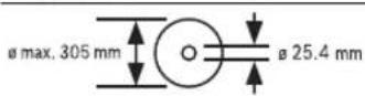
Observe the dimensions of the saw blade. The hole diameter must match the tool spindle without play. Do not use reducers or adapters.
natural_image
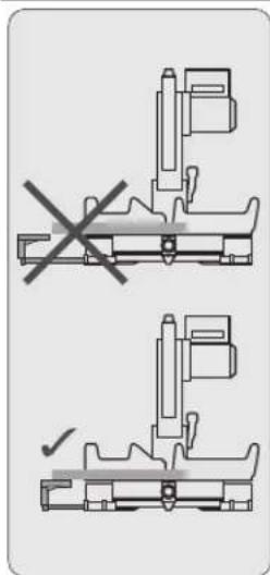
Mechanical assembly diagram showing two cross-sectional views with a checkmark indicating a detail (no text or symbols present)▶ Always adjust the saw-table extensions properly in order to underlay or support long workpieces at their free end. Workpieces that are not sufficiently underlaid can tilt or tip over during sawing. This can lead to injury or damage the power tool.
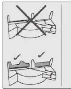
▶ Always saw with the distance-stops inserted. Without distance-stops, the contact surface is too small and the workpiece cannot be sufficiently secured for sawing.
Symbols and their meaning
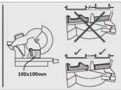
In order to saw workpieces higher than 75 mm, the distance-stops must be inserted at the front position on both sides. The distance-stops always must be in line to each other, so that a straight contact surface for the workpiece is achieved.
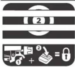
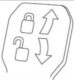
For adjustment of random mitre angles, the saw table must move freely and the mitre detent override must be blocked:
flowchart
graph TD
    A["Lock"] --> B["Up Arrow"]
    C["Unlock"] --> D["Down Arrow"]
- Pull lever ① and at the same time push the mitre detent override ② downward at the front.
Clamping lever shut:
The set bevel angle of the tool arm is locked.
Clamping lever open:
Adjusting bevel angles is possible.
Product Description and Specifications

Read all safety warnings and all instructions. Failure to follow the warnings and instructions may result in electric shock, fire and/or serious injury.
Intended Use
The power tool is intended as a stationary machine for making straight lengthways and crossways cuts in hard and softwood, as well as in particle and fibre board. In this, mitre angles from -52^ to +52^ as well as bevel angles from -2^ to +47^ are possible.
When using appropriate saw blades, sawing aluminium profiles and plastic is also possible.
English | 15
Product Features
The numbering of the components shown refers to the representation of the power tool on the graphic pages.
1 Dust bag
2 Extraction adapter
3 Transport handle
4 Handle
5 Retracting blade guard
6 Fence
7 Movable distance-stop
8 Mounting holes
9 Locking knob for various mitre angles
14 Clamping lever of the saw-table extension
15 Saw-table extension
16 Recessed handles
17 Hex key (6 mm/4 mm)
18 Adjustable fence
19 Stop for 45° and 33.9° standard bevel angle
20 Transport safety-lock
21 Spindle lock
22 Lever for releasing the tool arm
23 Clamping lever for any bevel angle
24 Scale for bevel angle
25 Indicator for bevel angle
26 Stop for 0° standard bevel angle
27 Material stop
28 Lock screw of the material stop
29 Detents for standard mitre angles
30 Saw table
31 On/Off switch
32 Blade guard
33 Cover plate
34 Saw blade
35 Roller
36 Insert plate
37 Material clamp
38 Clamping lever of the adjustable fence
39 Mounting holes for material clamp
40 Chip deflector
41 Chip ejector
42 Front fastening screw (cover plate/retracting blade guard)
43 Protection cover
44 Hex socket screw for mounting of saw blade
45 Clamping flange
46 Interior clamping flange
47 Cover plate tab
48 Wing bolt
49 Threaded rod
50 Clamping screw of the material stop
51 Screws for insert plate
52 Screw for bevel angle indicator
53 Stop screw for 0° bevel angle
54 Stop screw for 45^ bevel angle
55 Set screws of scale 13 for mitre angles
56 Screw for mitre angle indicator
57 Velcro strap
Accessories shown or described are not part of the standard delivery scope of the product. A complete overview of accessories can be found in our accessories program.
Technical Data
| Mitre Saw GCM 12 MX | ||
| Article number | 3 601 B21 1.. | |
| Rated power input | W 1800 | |
| No-load speed | min^-1 | 4300 |
| Weight according to EPTA-Procedure 01:2014 | kg 20.7 | |
| Protection class | ☐/II | |
Permissible workpiece dimensions (maximum/minimum) see page 18.
The values given are valid for a nominal voltage [U] of 230 V. For different voltages and models for specific countries, these values can vary.
Dimension of suitable saw blades
| Saw blade diameter | mm 305 |
| Blade body thickness | mm 1.7–2.62 |
| Mounting hole diameter | mm 25.4 |
Assembly
- Avoid unintentional starting of the machine. During assembly and for all work on the machine, the power plug must not be connected to the mains supply.
Delivery Scope
Carefully remove all parts included in the delivery from their packaging.
Remove all packaging material from the machine and the accessories provided.
Before starting the operation of the machine for the first time, check if all parts listed below have been supplied:
- Mitre saw with mounted saw blade
D u s t b a g 1
- Extraction adapter 2
- Material clamp 37
- H e x k e y 17
Note: Check the power tool for possible damage.
Before further use of the machine, check that all protective devices are fully functional. Any lightly damaged parts must be carefully checked to ensure flawless operation of the tool. All parts must be properly mounted and all conditions fulfilled that ensure faultless operation.


16 | English
Damaged protective devices and parts must be immediately replaced by an authorised service centre.
Stationary or Flexible Mounting
To ensure safe handling, the machine must be mounted on a level and stable surface (e.g., workbench) prior to using.
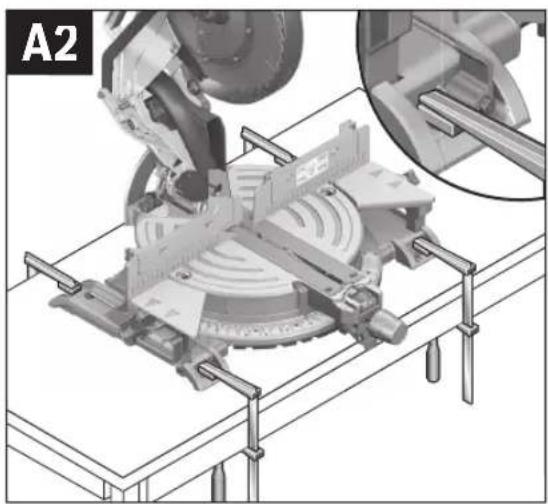
Mounting to a Working Surface (see figures A1 - A2)
- Fasten the power tool with suitable screw fasteners to the working surface. The mounting holes 8 serve for this purpose.
or
- Clamp the power tool with commercially available screw clamps by the feet to the working surface.
Mounting to a Bosch Saw Stand
With the height-adjustable legs, Bosch GTA saw stands provide firm support for the power tool on any surface. The workpiece supports of the saw stand are used for underlying long workpieces.
Read all safety warnings and instructions included with the worktable. Failure to observe safety warnings and instructions can lead to electrical shock, fire and/or cause serious injuries.
▶ Assemble the worktable properly before mounting the power tool. Perfect assembly is important in order to prevent the risk of collapsing.
- Mount the power tool in transport position on the saw stand.
Dust/Chip Extraction
Dust from materials such as lead-containing coatings, some wood types, minerals and metal can be harmful to one's health. Touching or breathing-in the dust can cause allergic reactions and/or lead to respiratory infections of the user or bystanders.
Certain dust, such as oak or beech dust, is considered carcinogenic, especially in connection with wood-treatment additives (chromate, wood preservative). Materials containing asbestos may only be worked by specialists.
- Always use dust extraction.
- Provide for good ventilation of the working place.
- It is recommended to wear a P2 filter-class respirator.
Observe the relevant regulations in your country for the materials to be worked.
▶ Prevent dust accumulation at the workplace. Dust can easily ignite.
The dust/chip extraction can be blocked by dust, chips or workpiece fragments.
- Switch the machine off and pull the mains plug from the socket outlet.
- Wait until the saw blade has come to a complete stop.
- Determine the cause of the blockage and correct it.
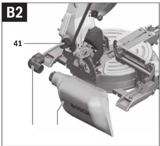
Integrated Dust Extraction (see figures B1-B2)
For basic dust collection, use the dust bag 1 provided.
▶ Check and clean the dust bag each time after using.
▶ When sawing aluminium, remove the dust bag to avoid the risk of fire.
- Mount the dust bag 1 onto the chip ejector 41.
or when space conditions are limited: - Firstly, mount extraction adapter 2 firmly onto chip ejector 41 and then mount dust bag 1 firmly onto extraction adapter 2.
During sawing, the dust bag and the extraction adapter may never come in contact with moving tool components.
Always empty the dust bag in good time.
External Dust Extraction
For dust extraction, you can also connect a vacuum hose to chip ejector 41 or extraction adapter 2.
- Insert the vacuum hose firmly into chip ejector 41 or extraction adapter 2.
The vacuum cleaner must be suitable for the material being worked.
When vacuuming dry dust that is especially detrimental to health or carcinogenic, use a special vacuum cleaner.
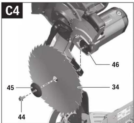
Changing the Saw Blade (see figures C1 - C4)
▶ Before any work on the machine itself, pull the mains plug.
▶ When mounting the saw blade, wear protective gloves.
Danger of injury when touching the saw blade.
Use only saw blades whose maximum permitted speed is higher than the no-load speed of the power tool.
Use only saw blades that correspond with the characteristic data given in these operation instructions and that are tested and marked in accordance with EN 847-1.
Use only saw blades recommended by the tool manufacturer, and suitable for sawing the materials to be cut. This prevents overheating of the saw teeth during sawing.
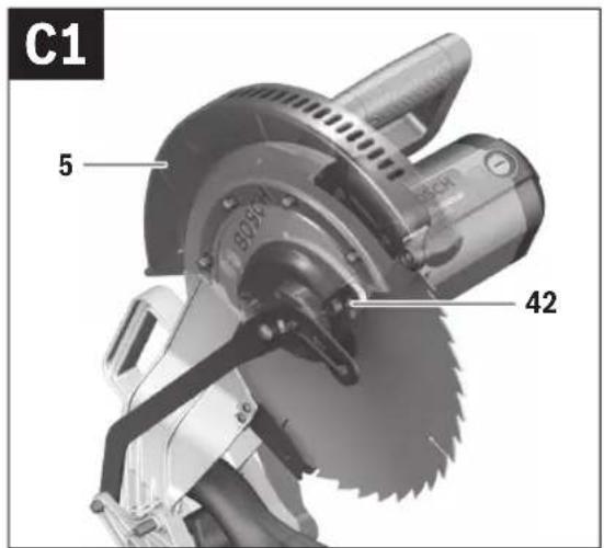
Removing the Saw Blade
- Bring the power tool into the working position.
- Press lever 22 and tilt the retracting blade guard 5 up to the stop.
Hold the retracting blade guard in this position.
- Loosen fastening screw 42 (approx. 4 turns) with the hex key (4 mm) 17.
Do not completely unscrew the screw.
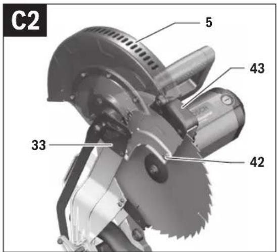
- Pull the retracting blade guard 5 and the cover plate 33 completely back until the retracting blade guard is held by the protection cover 43.
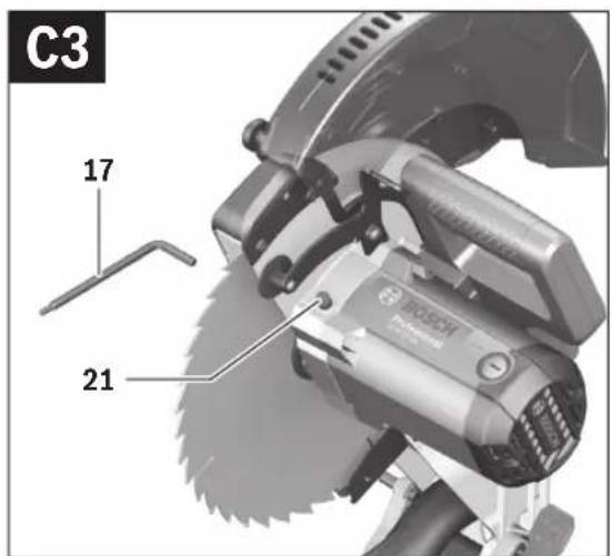
- Turn the hex socket screw 44 with the hex key (6 mm) 17 and at the same time press the spindle lock 21 until it engages.
- Hold the spindle lock 21 pressed and unscrew the hex socket screw 44 in clockwise direction (left-hand thread!).
- Remove the clamping flange 45.
- Remove the saw blade 34.
Mounting the Saw Blade
If required, clean all parts to be mounted prior to assembly.
- Place the new saw blade onto the interior clamping flange 46.


English | 17
When mounting the saw blade, pay attention that the cutting direction of the teeth (arrow direction on the saw blade) corresponds with the direction of the arrow on the blade guard!
- Place on the clamping flange 45 and the screw 44. Press the spindle lock 21 until it engages and tighten the screw turning in anticlockwise direction.
- Push the retracting blade guard 5 down toward the front until the respective recess of cover plate 33 engages under fastening screw 42 again.
For this, it is possible that you must counter-hold the tool arm by the handle to achieve the pre-tension of the retracting blade guard. - Press lever 22 and tilt the retracting blade guard 5 up to the stop.
Hold the retracting blade guard in this position. - Firmly tighten fastening screw 42 and guide the retracting blade guard down again.
Operation
▶ Before any work on the machine itself, pull the mains plug.
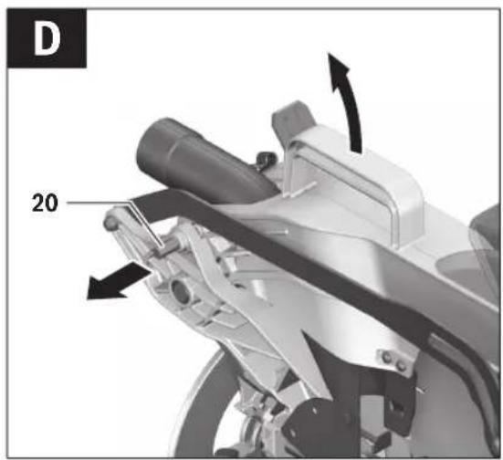
Transport Safety (see figure D)
The transport safety-lock 20 enables easier handling of the machine when transporting to various working locations.
Releasing the Machine (Working Position)
- Push the tool arm by the handle 4 down a little in order to relieve the transport safety-lock 20.
– Pull the transport safety-lock 20 completely outward. - Guide the tool arm slowly upward.
Securing the Machine (Transport Position)
- Press lever 22 and at the same time, push the tool arm by handle 4 downward until the transport safety-lock 20 can be pushed completely inward.
The tool arm is now securely locked for transport.
Preparing for Operation
Extending the Saw Table (see figure E)
Long workpieces must be underlaid or supported at their free end.
The saw table can be extended left and right with the saw-table extensions 15.
- Push clamping lever 14 upward.
– Pull out the saw-table extension 15 to the desired length. - To lock the saw-table extension, push clamping lever 14 down again.
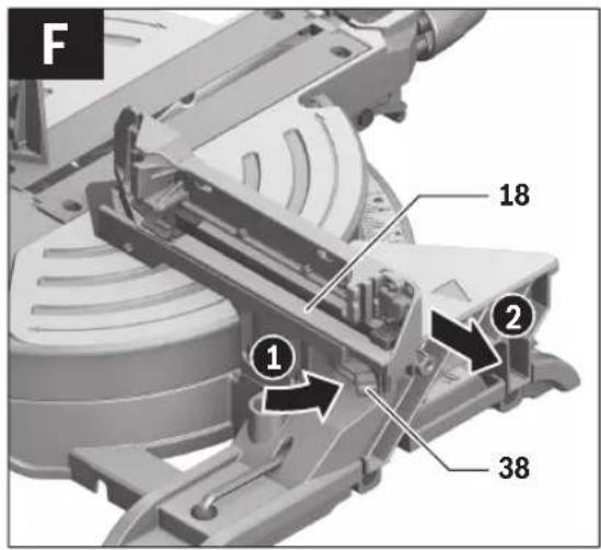
Moving the Fence (see figure F)
For bevel angles, the adjustable fence 18 must be moved.
- Turn clamping lever 38 toward the front
– Pull the adjustable fence 18 completely outward.
- To lock the adjustable fence, push clamping lever 38 down again.
- Turn clamping lever 38 toward the front - Pull the adjustable fence 18 completely outward. - To lock the adjustable fence, push clamping lever 38 down again.
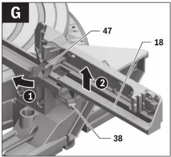
Removing the Adjustable Fence (see figure G)
For extreme bevel angles, the adjustable fence 18 must be removed completely.
- Pivot cover plate 47 outward.
- Turn clamping lever 38 toward the front.
- Pull the adjustable fence 18 completely outward.
- Remove the adjustable fence upward.
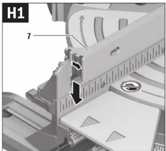
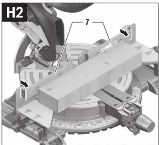
Repositioning Distance-stops (see figures H1–H2)
In order to saw workpieces higher than 75 mm, the distance-stops must be inserted at the front position on both sides.
- Pull the distance-stops 7 upward out of adjustable fence 18 (left) and out of fence 6 (right).
- Mount the distance-stops 7 again via the rear groove and push them to the stop into the fence extension 18 and fence 6.
The distance-stops must be heard to engage.
The distance-stops always must be in line to each other, so that a straight contact surface for the workpiece is achieved.
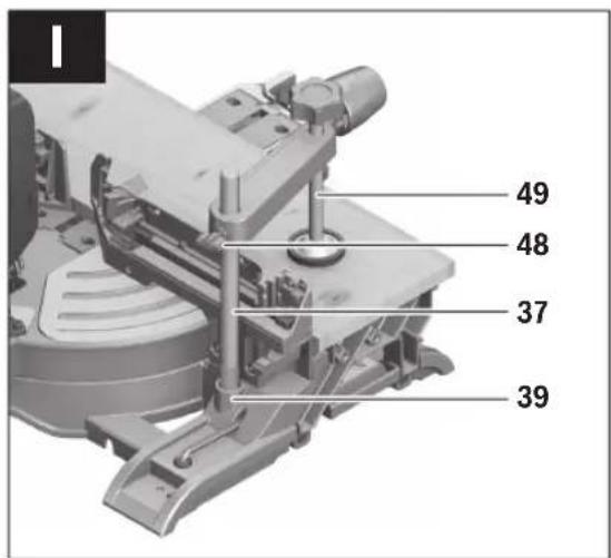
Clamping the Workpiece (see figure I)
To ensure optimum working safety, the workpiece must always be firmly clamped.
Do not saw workpieces that are too small to clamp.
- Press the workpiece firmly against the fence 6.
- Insert the material clamp 37 provided into one of the holes 39 intended for it.
- Loosen the wing bolt 48 and adapt the material clamp to the workpiece. Tighten the wing bolt again.
- Firmly clamp the workpiece by turning the threaded rod 49 in clockwise direction.
Adjusting Mitre Angles
To ensure precise cuts, the basic adjustment of the machine must be checked and adjusted as necessary after intensive use (see "Checking and Adjusting the Basic Adjustment", page 20).
▶ Always tighten the locking knob 9 firmly before sawing. Otherwise the saw blade can become wedged in the workpiece.
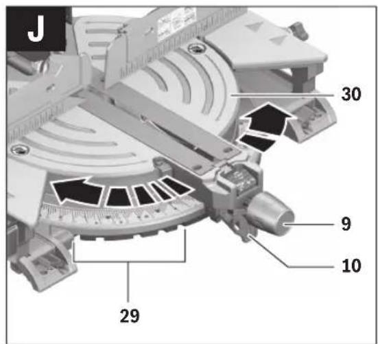
Adjusting Standard Mitre Angles (see figure J)
For quick and precise adjustment of commonly used mitre angles, detents 29 have been provided for on the saw table:
Left Right
0^
45^31.6^22.5^15^15^22.5^31.6^45^
- Loosen the locking knob 9 in case it is tightened.
- Pull lever 10 and rotate the saw table 30 left or right to the requested detent.
- Release the lever again. The lever must be felt to engage in the detent.
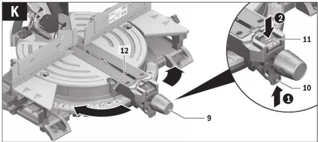
Adjusting Any Mitre Angle (see figure K)
The mitre angle can be set in the range from 52^ (left side) to 52^ (right side).
- Loosen the locking knob 9 in case it is tightened.
18 | English
- Pull lever 10 and at the same time, push mitre detent override 11 down at the front.
This locks lever 10 and the saw table can move freely. - Turn the saw table 30 left or right by the locking knob until the angle indicator 12 indicates the requested mitre angle.
- Tighten the locking knob 9 again.
- To loosen the lever 10 again (for adjusting standard mitre angles), pull the lever upward.
The mitre detent override 11 snaps back to its original position and lever 10 can re-engage into the detents 29.
Adjusting Bevel Angles
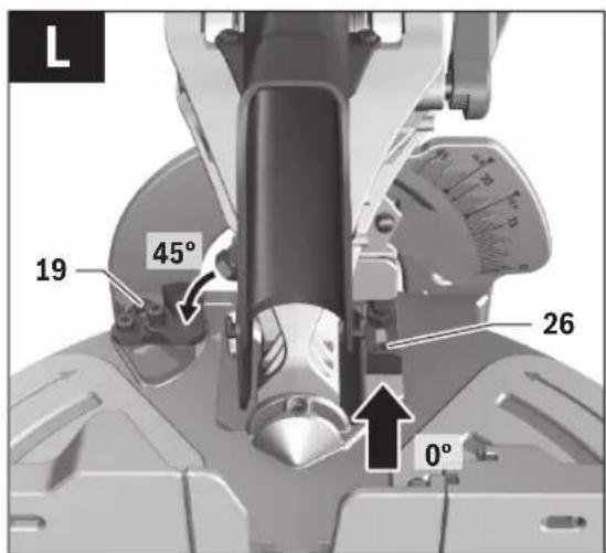
Adjusting Standard Bevel Angles (see figure L)
For quick and precise adjustment of commonly used bevel angles, stops are provided for 0°, 45° and 33.9° angles.
- Loosen clamping lever 23.
- Adjust stops 19 or 26 as follows:
Mitre/Bevel
Angle
Stop Adjustment
0° 26 Push the stop completely to the rear
45° 19 Turn the stop to the rear
33.9° 19 Turn the stop to the centre
- Swing the tool arm with the handle 4 to the requested position.
- Tighten clamping lever 23 again.
Adjusting Any Bevel Angle
The bevel angle can be set in a range from -2^ to +47^ .
- Loosen clamping lever 23.
- Turn stop 19 completely to the front and pull stop 26 completely to the front.
The complete tilting range is now available.
- Tilt the tool arm by the handle 4 until the angle indicator 25 indicates the desired bevel angle.
- Hold the tool arm in this position and tighten clamping lever 23 again.
Starting Operation
▶ Observe the mains voltage! The voltage of the power source must correspond with the data on the type plate of the machine.
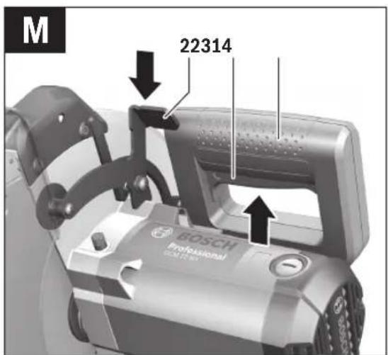
Switching On (see figure M)
To save energy, only switch the power tool on when using it.
- For starting operation, pull the On/Off switch 31 in the direction of the handle 4.
Note: For safety reasons, the On/Off switch 31 cannot be locked; it must remain pressed during the entire operation.
The tool arm can only be guided downward when pressing lever 22.
- For sawing, you must additionally press lever 22 in addition to actuating the On/Off switch 31.
Switching Off
- To switch off the machine, release the On/Off switch 31.
Working Advice
General Sawing Instructions
For all cuts, it must first be ensured that the saw blade at no time can come in contact with the fence, screw clamps or other machine parts. Remove any mounted auxiliary stops or adjust them accordingly.
Protect the saw blade against impact and shock. Do not subject the saw blade to lateral pressure.
Do not saw warped/bent workpieces. The workpiece must always have a straight edge to face against the fence.
Long workpieces must be underlaid or supported at their free end.
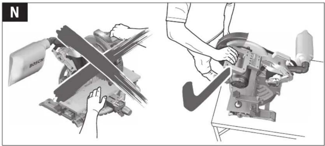
Position of the Operator (see figure N)
▶ Do not stand in a line with the saw blade in front of the machine. Always stand aside of the saw blade. This protects your body against possible kickback.
- Keep hands, fingers and arms away from the rotating saw blade.
- Do not cross your arms when operating the tool arm.
Permissible Workpiece Dimensions
Maximum workpiece sizes:
| Mitre/Bevel Angle Height x Width [mm] | |||
| Horizontal | Vertical | Workpiece against fence | Workpiece against distance-stop (moved toward the front) |
| 0° | 0° | 75 x 200 | 100 x 150 |
| 45° | 0° | 75 x 141 | 100 x 100 |
| 0° | 45° | 38 x 200 | - |
| 45° | 45° | 38 x 141 | - |
Minimum workpiece sizes
(= all workpieces that can be clamped left or right from the saw blade with the supplied material clamp 37):
128 x 40 mm (length x width)
Cutting depth, max.
Workpiece against fence (0°/0°): 75 mm
Workpiece against distance-stop
(moved toward the front) (0°/0°): 100 mm
English | 19
Cutting Off
- Firmly clamp the workpiece as appropriate for its dimensions.
- Adjust the requested mitre and/or bevel angle.
- Switch on the machine.
- Press lever 22 and slowly guide the tool arm downward by handle 4.
- Saw through the workpiece applying uniform feed.
- Switch off the machine and wait until the saw blade has come to a complete stop.
– Guide the tool arm slowly upward.
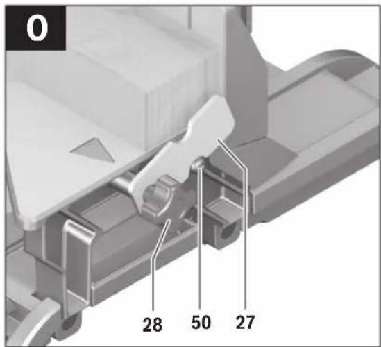
Sawing Workpieces of the Same Length (see figure O)
The material stop 27 can be used for easily sawing workpieces to the same length.
The material stop can be mounted on either side of the saw table extension 15.
- Loosen lock screw 28 and swing the material stop 27 over clamping screw 50.
- Retightenlockscrew 28.
- Adjust the saw table extension 15 to the desired length (see "Extending the Saw Table", page 17).
Special Workpieces
When sawing curved or round workpieces, these must be especially secured against slipping. At the cutting line, no gap may exist between workpiece, fence and saw table.
Provide for special fixtures, if required.
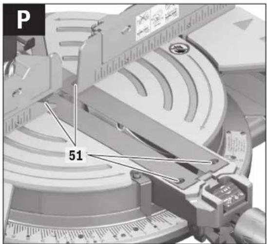
Replacing Insert Plates (see figure P)
The red insert plates 36 can become worn after prolonged use of the machine.
Replace defective insert plates.
- Bring the power tool into the working position.
- Unscrew screws 51 with the provided hex key (4 mm) 17 and remove the old insert plates.
- Insert the new right-hand insert plate.
- Screw the insert plate with the screws 51 as far as possible to the right, so that the saw blade does not come in contact with the insert plate throughout the complete possible ripping length.
- Repeat the work steps in the same manner for the left-hand insert plate.
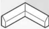
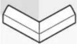
Sawing Profile Strips/Mouldings (Floor and Ceiling Strips)
Profile strips/mouldings can be sawn in two different ways:
- Placed against the fence
- Lying flat on the saw table.
Always make trial cuts with the mitre angle setting first on scrap wood.
Floor Strips/Mouldings
The following table contains instructions for sawing floor strips/mouldings.
| Settings Placed | against the fence | Lying flat on the saw table |
| Bevel angle 0° 45° |
| Floor strip/moulding | Left side Right side Left side Right side | ||||
| Inner corner Horizontal mitre angle | 45^ left 45^ right 0^ 0^ | ||||
 | Positioning of work-piece | Bottom edge on saw table | Bottom edge on saw table | Upper edge against the fence | Bottom edge against the fence |
| The finished work-piece is located ... | ... to the left of the cut | ... to the right of the cut | ... to the left of the cut | ... to the left of the cut | |
| Outer corner | Horizontal mitre angle | 45^ right | 45^ left | 0^ | 0^ |
 | Positioning of work-piece | Bottom edge on saw table | Bottom edge on saw table | Bottom edge against the fence | Upper edge against the fence |
| The finished work-piece is located ... | ... to the left of the cut | ... to the right of the cut | ... to the right of the cut | ... to the right of the cut | |
20 | English
Ceiling Strips/Mouldings (According to US Standard)
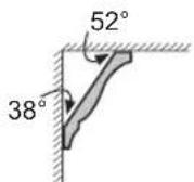
When the ceiling strips/mouldings are to be sawn lying flat on the saw table, the standard mitre angles of 31.6^ (horizontal) and 33.9^ (vertical) must be set. The following table contains instructions for sawing ceiling strips/mouldings.
| Settings Placed | against the fence | 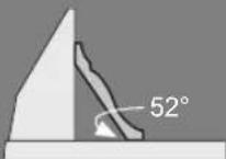 | Lying flat on the saw table | 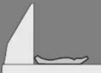 | |
| Bevel angle 0° 33,9° | |||||
| Ceiling strip/moulding | Left side Right side Left side Right side | ||||
| Inner corner Horizontal mitre angle | 45° right 45° left 31.6° right 31.6° left | ||||
| Positioning of work-piece | Bottom edge against the fence | Bottom edge against the fence | Upper edge against the fence | Bottom edge against the fence | |
| The finished work-piece is located ... | ... to the right of the cut | ... to the left of the cut | ... to the left of the cut | ... to the left of the cut | |
| Outer corner | Horizontal mitre angle | 45° left 45° right 31.6° left 31.6° right | |||
| Positioning of work-piece | Bottom edge against the fence | Bottom edge against the fence | Bottom edge against the fence | Upper edge against the fence | |
| The finished work-piece is located ... | ... to the right of the cut | ... to the left of the cut | ... to the right of the cut | ... to the right of the cut | |
Checking and Adjusting the Basic Adjustment
To ensure precise cuts, the basic adjustment of the machine must be checked and adjusted as necessary after intensive use.
A certain level of experience and appropriate specialty tools are required for this.
A Bosch after-sales service station will handle this maintenance task quickly and reliably.
Setting the Standard Bevel Angle 0° (Vertical)
- Bring the power tool into the working position.
- Turn the saw table 30 to the 0^ detent 29. The lever 10 must be felt to engage in the detent.
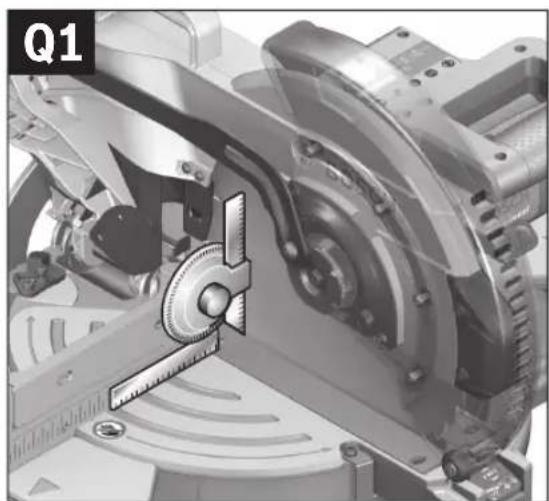
Checking: (see figure Q1)
- Adjust an angle gauge to 90^ and position it on the saw table 30.
The leg of the angle gauge must be flush with the saw blade 34 over the complete length.
Adjusting: (see figure Q2)
- Loosen clamping lever 23.
- Push the stop 26 completely to the rear.
- Loosen the lock nut of the stop screw 53 using a commercial box-end or open-end spanner (size 13 mm).
- Screw the stop screw in or out until the leg of the angle gauge is flush with the saw blade over the complete length.
- Tighten clamping lever 23 again.
- Afterwards, retighten the lock nut of the stop screw 53 again. In case the angle indicator 25 is not in a line with the 0° mark of the scale 24 after the adjustment, loosen the screw 52 using a commercial cross-head screwdriver and align the angle indicator along the 0° mark.
Setting the Standard Bevel Angle 45° (Vertical)
- Bring the power tool into the working position.
- Turn the saw table 30 to the 0^ detent 29. The lever 10 must be felt to engage in the detent.
- Turn the stop 19 completely to the rear.
- Loosen clamping lever 23 and tilt the tool arm by handle 4 leftward to the stop (45°).
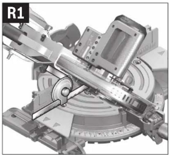
Checking: (see figure R1)
- Adjust an angle gauge to 45^ and position it on the saw table 30.
The leg of the angle gauge must be flush with the saw blade 34 over the complete length.
Adjusting: (see figure R2)
- Loosen the lock nut of the stop screw 54 using a commercial box-end or open-end spanner (size 13 mm).
- Screw the stop screw in or out until the leg of the angle gauge is flush with the saw blade over the complete length.
- Tightenclamajn.inglever 23ag
- Afterwards, retighten the lock nut of the stop screw 54 again.
English | 21
In case the angle indicator 25 is not in a line with the 45^ mark of the scale 24, firstly check the 0^ setting for the bevel angle and the angle indicator again. Then repeat the adjustment of the 45^ bevel angle.
Aligning the Scale for Mitre Angles
- Bring the power tool into the working position.
- Turn the saw table 30 to the 0^ detent 29. The lever 10 must be felt to engage in the detent.
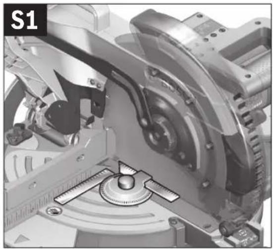
Checking: (see figure S1)
- Adjust an angle gauge to 90^ and position it between the fence 6 and the saw blade 34 on the saw table 30.
The leg of the angle gauge must be flush with the saw blade 34 over the complete length.
Adjusting: (see figure S2)
- Loosen all four set screws 55 with the hex key (4 mm) 17 and turn the saw table 30 together with the scale 13 until the leg of the angle gauge is flush with the saw blade over the complete length.
- Retighten the screws again.
When the angle indicator 12 is not in line with the 0° mark of scale 13 after adjusting, loosen screw 56 with a cross-head screwdriver and align the angle indicator alongside the 0° mark.
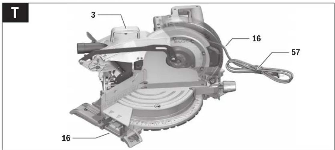
Transport (see figure T)
Before transporting the power tool, the following steps must be carried out:
- Guide the tool arm downward until the transport safety-lock 20 can be pushed completely inward.
- Slide the saw-table extensions 15 completely in and lock them in place (by pushing clamping lever 14 down).
- Adjust a 0^ bevel angle and tighten clamping lever 23.
- Turn saw table 30 rightward to the stop and tighten locking knob 9.
- Wind up the mains cable and tie it together with Velcro strap 57.
- Remove all accessories that cannot be mounted firmly to the power tool. If possible, place unused saw blades in an enclosed container for transport.
- Carry the machine by the transport handle 3 or hold it by the recessed handles 16 on the sides of the saw table.
▶ When transporting the power tool, use only the transport devices and never use the protective devices.
Maintenance and Service
Maintenance and Cleaning
▶ Before any work on the machine itself, pull the mains plug.
If the replacement of the supply cord is necessary, this has to be done by Bosch or an authorized Bosch service agent in order to avoid a safety hazard.
Cleaning
For safe and proper working, always keep the power tool and its ventilation slots clean.
The retracting blade guard must always be able to move freely and retract automatically. Therefore, always keep the area around the retracting blade guard clean.
Remove dust and chips after each working procedure by blowing out with compressed air or with a brush.
Clean the roller 35 regularly.
Accessories
| Article number | |||
| Material clamp 1 609 B02 585 | |||
| Dust bag 1 609 B01 716 | |||
| Angle adapter for dust bag 1 609 B01 613 | |||
| Saw blades | |||
| Outer diameter Bore | Number of teeth | ||
| AUS 305 25.4 | 60 | 2 608 673 049 | |
| KOR 305 25.4 | 100 | 1 609 B01 739 | |
| CN, IN | 305 25.4 | 120 | 2 608 642 207 |
After-sales Service and Application Service
Our after-sales service responds to your questions concerning maintenance and repair of your product as well as spare parts. Exploded views and information on spare parts can also be found under:
www.bosch-pt.com
Bosch's application service team will gladly answer questions concerning our products and their accessories.
In all correspondence and spare parts orders, please always include the 10-digit article number given on the nameplate of the product.
People's Republic of China
China Mainland
Bosch Power Tools (China) Co., Ltd.
567, Bin Kang Road
Bin Jiang District 310052
Hangzhou, P.R.China
Service Hotline: 4008268484
Fax: (0571) 87774502
E-Mail: contact.ptcn@cn.bosch.com
www.bosch-pt.com.cn
HK and Macau Special Administrative Regions
Robert Bosch Hong Kong Co. Ltd.
21st Floor, 625 King's Road
North Point, Hong Kong
Customer Service Hotline: +852 2101 0235
Fax: +852 2590 9762
E-Mail: info@hk.bosch.com
www.bosch-pt.com.hk


22 | English
Indonesia
PT Robert Bosch
Palma Tower 10 ^th Floor
Jl. RA Kartini II-S Kaveling 6 Sek II
Pondok Pinang, Kebayoran Lama
28th Floor Fort Legend Towers,
3rd Avenue corner 31st Street,
Fort Bonifacio Global City,
1634 Taguig City, Philippines
Tel.: (02) 8703871
Fax: (02) 8703870
matheus.contiero@ph.bosch.com
www.bosch-pt.com.ph
Bosch Service Center:
9725-27 Kamagong Street
San Antonio Village
Makati City, Philippines
Tel.: (02) 8999091
Fax: (02) 8976432
E-Mail: rosalie.dagdagan@ph.bosch.com
Malaysia
Robert Bosch Sdn. Bhd.
No. 8A, Jalan 13/6
G.P.O. Box 10818
46200 Petaling Jaya
Selangor, Malaysia
Tel.: (03) 79663194
Fax: (03) 79583838
E-Mail: cheehoe.on@my.bosch.com
Toll-Free: 1800 880188
www.bosch-pt.com.my
Thailand
Robert Bosch Ltd.
Liberty Square Building
No. 287, 11 Floor
Silom Road, Bangrak
Bangkok 10500
Tel.: 02 6393111
Fax: 02 2384783
Robert Bosch Ltd., P. O. Box 2054
Bangkok 10501, Thailand
www.bosch.co.th
Bosch Service – Training Centre
La Salle Tower Ground Floor Unit No.2
10/11 La Salle Moo 16
Srinakharin Road
Bangkaew, Bang Plee
Samutprakarn 10540
Thailand
Tel.: 02 7587555
Fax: 02 7587525
Singapore
Powerwell Service Centre Ptd Ltd
65 Ubi Crescent, #06-03 Hola Centre
Singapore 408559
Tel.: 6746 9770/71
Fax: 6746 9760
E-Mail: powerwellsc@gmail.com
Toll-Free: 1800 3338333
www.bosch-pt.com.sg
Vietnam
Robert Bosch Vietnam Co. Ltd
13th Floor, 194 Golden Building
473 Dien Bien Phu Street
Ward 25, Binh Thanh District
84 Ho Chi Minh City
Vietnam
Tel.: (08) 6258 3690
Fax: (08) 6258 3692
Hotline: (08) 6250 8555
E-Mail: tuvankhachhang-pt@vn.bosch.com
www.bosch-pt.com.vn
www.baohanhbosch-pt.com.vn
Australia, New Zealand and Pacific Islands
Robert Bosch Australia Pty. Ltd.
Power Tools
Locked Bag 66
Clayton South VIC 3169
Customer Contact Center
Inside Australia:
Phone: (01300) 307044
Fax: (01300) 307045
Inside New Zealand:
Phone:(0800)543353
Fax: (0800) 428570
Outside AU and NZ:
Phone: +61 3 95415555
www.bosch-pt.com.au
www.bosch-pt.co.nz
Egypt
Unimar
20 Markaz kadmat
El tagmoa EL Aoul - New Cairo
Tel: +2 02 224 76091 - 95 / + 2 02 224 78072 - 73
Fax:+2 02 224 78075
E-Mail: adelzaki@unimaregypt.com
中文|23
Ethiopia
Forever plc
Kebele 2,754, BP 4806,
Addis Ababa, Ethiopia
Tel: +251 111 560 600, +251 111 560 600
E-Mail: foreverplc@ethionet.et
Nigeria
C. Woermann Ltd.
P.O. Box 318
6, Badejo Kalesanwo Street
Matori Industrial Estate
Lagos, Nigeria
Tel: +234 17 736 498, +234 17 730 904
E-Mail: d.kornemann@woermann-nigeria.com
Republic of South Africa
Customer service
Hotline: (011) 6519600
Gauteng - BSC Service Centre
35 Roper Street, New Centre
Johannesburg
Tel.: (011) 4939375
Fax: (011) 4930126
E-Mail: bsctools@icon.co.za
KZN - BSC Service Centre
Unit E, Almar Centre
143 Crompton Street
Pinetown
Tel.: (031) 7012120
Fax: (031) 7012446
E-Mail: bsc.dur@za.bosch.com
Western Cape - BSC Service Centre
Democracy Way, Prosperity Park
Milnerton
Tel.: (021) 5512577
Fax: (021) 5513223
E-Mail: bsc@zsd.co.za
Bosch Headquarters
Midrand, Gauteng
Tel.: (011) 6519600
Fax: (011) 6519880
E-Mail: rbsa-hq.pts@za.bosch.com
Disposal
The machine, accessories and packaging should be sorted for environmental-friendly recycling.
Do not dispose of power tools into household waste!
Subject to change without notice.
中文
安全规章
电动工具通用安全警告
natural_image
Technical line drawing of mechanical components with no visible text or symbolsnatural_image
Technical line drawing of mechanical components with no visible text or symbolsnatural_image
Simple line drawing of a shield with four symbols: lock, open padlock, and directional arrows (no text or labels)natural_image
Technical diagram showing two mechanical assembly states with a cross symbol indicating no change or restriction (no text or labels present)| 0^ | |||||||||
| 45^ | 31.6^ | 22.5^ | 15^ | 15^ | 22.5^ | 31.6^ | |||
Mechanics and Electronics Ltd.
PT/SAX-ASA
298 Bojeong-dong Giheung-gu
Yongin-si, Gyeonggi-do, 446-913
Republic of Korea
080-955-0909
처리
natural_image
Mechanical assembly diagram showing two cross-sectional views with a checkmark indicating a specific part (no text or symbols present)natural_image
Technical illustration showing two mechanical assembly states with crosshair marks (no text or symbols)natural_image
Technical line drawing of mechanical components with no visible text or symbolsflowchart
graph TD
    A["Lock"] --> B["Up Arrow"]
    C["Unlock"] --> D["Down Arrow"]
natural_image
Mechanical assembly diagram showing two cross-sectional views with a checkmark indicating a specific part (no text or symbols present)flowchart
graph TD
    A["Lock"] --> B["Up Arrow"]
    C["Unlock"] --> D["Down Arrow"]