
GBH 2400 Professional - Hammer BOSCH - Free user manual and instructions
Find the device manual for free GBH 2400 Professional BOSCH in PDF.
| Product Type | Rotary Hammer |
| Brand | Bosch |
| Model | GBH 2400 Professional |
| Rated power input | 720 W |
| Speed | 0–900 rpm |
| Impact rate | 0–4000 rpm |
| Single impact energy | 2 J (according to EPTA 05/2009) |
| Max. drilling diameter in concrete | 24 mm |
| Max. drilling diameter in masonry | 68 mm (with core cutter) |
| Max. drilling diameter in steel | 13 mm |
| Max. drilling diameter in wood | 30 mm |
| Tool holder | SDS-plus |
| Weight | 2.7 kg (according to EPTA 01:2014) |
| Protection class | II (double insulation) |
| Sound pressure level | 91 dB(A) |
| Sound power level | 102 dB(A) |
| Vibration (drilling in concrete) | 17.5 m/s² (total value) |
| Functions | Drilling with/without impact, chiseling, forward/reverse rotation, variable speed, Vario-Lock (36 chisel positions) |
| Included accessories | Auxiliary handle, depth stop, dust protection cap |
| Maintenance | Clean ventilation slots, replace damaged dust protection cap |
| Safety | Overload clutch, switch lock, recommended hearing protection |
Frequently Asked Questions - GBH 2400 Professional BOSCH
User questions about GBH 2400 Professional BOSCH
0 question about this device. Answer the ones you know or ask your own.
Ask a new question about this device
Download the instructions for your Hammer in PDF format for free! Find your manual GBH 2400 Professional - BOSCH and take your electronic device back in hand. On this page are published all the documents necessary for the use of your device. GBH 2400 Professional by BOSCH.
USER MANUAL GBH 2400 Professional BOSCH
OB1_BUCH-861-007.buck Page 1 Thursday, April 28, 2016 1-42 PM
Robert Bosch Power Tools GmbH
70538 Stullgart
GERMANY
www.bosch-pt.com
160992A2A6(2016.06)PS/193
GBH 2400 Professional

BOSCH
mkOpHAnIOyIaTc3g3aBcTa
sr Original no upstvo za rad
slzema naovodila
hrOrinalne upoetza rad
et Alguparane kasusujhend
Instrukcijas originala
It Original instruKja
ko
H
fa 1


Deutsch. 6
English . Page 11
Francais 17
Espanol. Pagsina 23
Portugues Pagina 29
Italiano 35
Nederlands.. 41
Dansk Side 47
Svenska Sida 52
Norsk. Side 57
Suomi . Sivu 62
EAAyivka 67
Türkce. Sayfa 73
Polski Strona 79
Cesky Strana 85
Slovensky Strana 90
Magyar Oldal 95
Pycckn CtpaHua 102
YkpaiHcbKa CtopiHa 109
Kaazka. 5er 115
Romana. 121
Былгарский.. .. 127
MaKeEOHcKn ..CtpaHa 133
Srpski Strana 139
Slovensko Stran 144
General Power Tool SafetyWarnings

WARNING
Read all safety warnings and all instructions. Failure to follow the warnings and
instructions may result in electric shock, fire and/or serious injury.
Save all warnings and instructions for future reference.
The term "power tool" in the warnings refers to your mains-operated (corded) power tool or battery-operated (cordless) power tool.
12 | English
Work area safety
- Keep work area clean and well lit. Cluttered or dark areas invite accidents.
Do not operate power tools in explosive atmospheres, such as in the presence of flammable liquids, gases or dust. Power tools create sparks which may ignite the dust or fumes. - Keep children and bystanders away while operating a power tool. Distractions can cause you to lose control.
Electrical safety
Power tool plugs must match the outlet. Never modify the plug in any way. Do not use any adapter plugs with earthed (grounded) power tools. Unmodified plugs and matching outlets will reduce risk of electric shock.
- Avoid body contact with earthed or grounded surfaces, such as pipes, radiators, ranges and refrigerators. There is an increased risk of electric shock if your body is earthed or grounded.
Do not expose power tools to rain or wet conditions. Water entering a power tool will increase the risk of electric shock.
Do not abuse the cord. Never use the cord for carrying, pulling or unplugging the power tool. Keep cord away from heat, oil, sharp edges or moving parts. Damaged or entangled cords increase the risk of electric shock.
- When operating a power tool outdoors, use an extension cord suitable for outdoor use. Use of a cord suitable for outdoor use reduces the risk of electric shock.
If operating a power tool in a damp location is unavoidable, use a residual current device (RCD) protected supply. Use of an RCD reduces the risk of electric shock.
Personal safety
Stay alert, watch what you are doing and use common sense when operating a power tool. Do not use a power tool while you are tired or under the influence of drugs, alcohol or medication. A moment of inattention while operating power tools may result in serious personal injury.
Use personal protective equipment. Always wear eye protection. Protective equipment such as dust mask, non-skid safety shoes, hard hat, or hearing protection used for appropriate conditions will reduce personal injuries.
Prevent unintentional starting. Ensure the switch is in the off-position before connecting to power source and/or battery pack, picking up or carrying the tool. Carrying power tools with your finger on the switch or energising power tools that have the switch on invites accidents.
- Remove any adjusting key or wrench before turning the power tool on. A wrench or a key left attached to a rotating part of the power tool may result in personal injury.
Do not overreach. Keep proper footing and balance at all times. This enables better control of the power tool in unexpected situations.
Dress properly. Do not wear loose clothing or jewellery. Keep your hair, clothing and gloves away from moving parts. Loose clothes, jewellery or long hair can be caught in moving parts.
If devices are provided for the connection of dust extraction and collection facilities, ensure these are connected and properly used. Use of dust collection can reduce dust-related hazards.
Power tool use and care
Do not force the power tool. Use the correct power tool for your application. The correct power tool will do the job better and safer at the rate for which it was designed.
Do not use the power tool if the switch does not turn it on and off. Any power tool that cannot be controlled with the switch is dangerous and must be repaired.
- Disconnect the plug from the power source and/or the battery pack from the power tool before making any adjustments, changing accessories, or storing power tools. Such preventive safety measures reduce the risk of starting the power tool accidentally.
- Store idle power tools out of the reach of children and do not allow persons unfamiliar with the power tool or these instructions to operate the power tool. Power tools are dangerous in the hands of untrained users.
- Maintain power tools. Check for misalignment or binding of moving parts, breakage of parts and any other condition that may affect the power tool's operation. If damaged, have the power tool repaired before use. Many accidents are caused by poorly maintained power tools.
- Keep cutting tools sharp and clean. Properly maintained cutting tools with sharp cutting edges are less likely to bind and are easier to control.
- Use the power tool, accessories and tool bits etc. in accordance with these instructions, taking into account the working conditions and the work to be performed. Use of the power tool for operations different from those intended could result in a hazardous situation.
Service
Have your power tool serviced by a qualified repair person using only identical replacement parts. This will ensure that the safety of the power tool is maintained.
Hammer SafetyWarnings
Wear ear protectors. Exposure to noise can cause hearing loss.
Use auxiliary handle(s), if supplied with the tool. Loss of control can cause personal injury.
Hold the tool by the insulated gripping surfaces when performing operations where the application tool or the screw could contact hidden wiring or its own power cord. Contact with a "live" wire will also make exposed metal parts of the power tool "live" and shock the operator.
Use suitable detectors to determine if utility lines are hidden in the work area or call the local utility company for assistance. Contact with electric lines can lead to fire


English|13
and electric shock. Damaging a gas line can lead to explosion. Penetrating a water line causes property damage or may cause an electric shock.
When working with the machine, always hold it firmly with both hands and provide for a secure stance. The power tool is guided more secure with both hands.
Secure the workpiece. A workpiece clamped with clamping devices or in a vice is held more secure than by hand.
Always wait until the machine has come to a complete stop before placing it down. The tool insert can jam and lead to loss of control over the power tool.
- Products sold in GB only: Your product is fitted with a BS 1363/A approved electric plug with internal fuse (ASTA approved to BS 1362). If the plug is not suitable for your socket outlets, it should be cut off and an appropriate plug fitted in its place by an authorised customer service agent. The replacement plug should have the same fuse rating as the original plug. The severed plug must be disposed of to avoid a possible shock hazard and should never be inserted into a mains socket elsewhere.
Products sold in AUS and NZ only: Use a residual current device (RCD) with a rated residual current of 30mA or less.
Product Description and Specifications

Read all safety warnings and all instructions. Failure to follow the warnings and instructions may result in electric shock, fire and/or serious injury.
While reading the operating instructions, unfold the graphics page for the machine and leave it open.
Intended Use
The machine is intended for hammer drilling in concrete, brick and stone, as well as for light chiselling work. It is also suitable for drilling without impact in wood, metal, ceramic and plastic. Machines with electronic control and right/left rotation are also suitable for screwdriving.
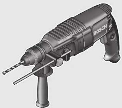
Product Features
The numbering of the product features refers to the illustration of the machine on the graphics page.
1 SDS-plus tool holder
2 Dust protection cap
3 Locking sleeve
4 Rotational direction switch
5 Lock-on button for On/Off switch
6 On/Off switch
7 Handle (insulated gripping surface)
8 Release button for mode selector switch
9 Mode selector switch
10 Button for depth stop adjustment
11 Depth stop
12 Auxiliary handle (insulated gripping surface)
13 Securing screw for key type drill chuck
14 Key type drill chuck
15 SDS-plus adapter shank for drill chuck
16 Extraction sleeve of the dust extraction attachment
17 Clamping screw for the dust extraction attachment
18 Depth stop of the dust extraction attachment
19 Telescopic pipe of the dust extraction attachment
20 Wing bolt of the dust extraction attachment
21 Guide pipe of the dust extraction attachment
22 Universal bit holder with SDS-plus shank
- Accessories shown or described are not part of the standard delivery scope of the product. A complete overview of accessories can be found in our accessories program.
Technical Data
| Rotary Hammer GBH 2400 | ||
| Article number | 0611 2538.. | |
| Speed control | ● | |
| Stop rotation | ● | |
| Right/left rotation | ● | |
| Rated power input | W | 720 |
| Impact rate | min-1 | 0-4000 |
| Impact energy per stroke according to EPTA-Procedure 05/2009 | J | 2.7 |
| Speed | min-1 | 0-900 |
| Tool holder | SDS-plus | |
| Spindle collar diameter | mm 50 | |
| Drilling diameter, max.: | ||
| - C on c r e t e | mm | 24 |
| - Brickwork (with core bit) | mm | 68 |
| - Steel | mm | 13 |
| - Wood | mm | 30 |
| Weight according to EPTA-Procedure 01:2014 | kg 2.7 | |
Protection class
□/11
The values given are valid for a nominal voltage [U] of 230 V. For different voltages and models for specific countries, these values can vary.
Noise/Vibration Information
Sound emission values determined according to EN60745-2-6.
Typically the A-weighted noise levels of the product are: Sound pressure level 91 dB(A);Sound power level 102 dB(A). Uncertainty K = 3 dB.
Wear hearing protection!
Vibration total values ah (triax vector sum) and uncertainty K determined according to EN 60745-2-6:
Hammer drilling into concrete: ah = 17.5 m/s , K = 1.5 m/s2 Chiselling: as = 14 m/s2 , K = 1.5 m/s2
Drilling into metal: ah < 2.5 m/s2 , K = 1.5 m/s2
Screwdriving without impact: ah < 2.5m / s2 K = 1.5m / s2
14|English
The vibration level given in this information sheet has been measured in accordance with a standardised test given in EN 60745 and may be used to compare one tool with another. It may be used for a preliminary assessment of exposure. The declared vibration emission level represents the main applications of the tool. However if the tool is used for different applications, with different accessories or insertion tools or is poorly maintained, the vibration emission may differ. This may significantly increase the exposure level over the total working period.
An estimation of the level of exposure to vibration should also take into account the times when the tool is switched off or when it is running but not actually doing the job. This may significantly reduce the exposure level over the total working period.
Identify additional safety measures to protect the operator from the effects of vibration such as: maintain the tool and the accessories, keep the hands warm, organisation of work patterns.
Assembly
Before any work on the machine itself, pull the mains plug.
Auxiliary Handle
Operate your machine only with the auxiliary handle 12.
Changing the position of the auxiliary handle (see figure A)
The auxiliary handle 12 can be set to any position for a secure and low-fatigue working posture.
Turn the bottom part of the auxiliary handle 12 in counterclockwise direction and swivel the auxiliary handle 12 to the desired position. Then retighten the bottom part of the auxiliary handle 12 by turning in clockwise direction.
Pay attention that the clamping band of the auxiliary handle is positioned in the groove on the housing as intended for.
Adjusting the Drilling Depth (see figure B)
The required drilling depth X can be set with the depth stop 11.
- Press the button for the depth stop adjustment 10 and insert the depth stop into the auxiliary handle 12. The knurled surface of the depth stop 11 must face downward.
- Insert the SDS-plus drilling tool to the stop into the SDS-plus tool holder 1. Otherwise, the movability of the SDS-plus drilling tool can lead to incorrect adjustment of the drilling depth.
- Pull out the depth stop until the distance between the tip of the drill bit and the tip of the depth stop corresponds with the desired drilling depth X .
Selecting Drill Chucks and Tools
For hammer drilling and chiselling, SDS-plus tools are required that are inserted in the SDS-plus drill chuck.
For drilling without impact in wood, metal, ceramic and plastic as well as for screwdriving, tools without SDS-plus are
used (e.g., drill bits with cylindrical shank). For these tools, a keyless chuck or a key type drill chuck are required.
Changing the Key Type Drill Chuck
To work with tools without SDS-plus (e.g., drills with cylindrical shank), a suitable drill chuck must be mounted (key type drill chuck or keyless chuck, accessories).
Mounting the Key Type Drill Chuck (see figure C)
- Screw the SDS-plus adapter shank 15 into a key type drill chuck 14. Secure the key type drill chuck 14 with the securing screw 13. Please observe that the securing screw has a left-hand thread.
Inserting the Key Type Drill Chuck (see figure C)
- Clean the shank end of the adapter shank and apply a light coat of grease.
- Insert the key type drill chuck with the adapter shank into the tool holder with a turning motion until it automatically locks.
- Check the locking effect by pulling the key type drill chuck.
Removing the Key Type Drill Chuck
Push the locking sleeve 3 toward the rear and pull out the key type drill chuck 14.
Changing the Tool
The dust protection cap 2 largely prevents the entry of drilling dust into the tool holder during operation. When inserting the tool, take care that the dust protection cap 2 is not damaged.
A damaged dust protection cap should be changed immediately. We recommend having this carried out by an after-sales service.
Inserting SDS-plus Drilling Tools (see figure D)
The SDS-plus drill chuck allows for simple and convenient changing of drilling tools without the use of additional tools.
- Clean and lightly grease the shank end of the tool.
- Insert the tool in a twisting manner into the tool holder until it latches itself.
- Check the latching by pulling the tool.
As a requirement of the system, the SDS-plus drilling tool can move freely. This causes a certain radial run-out at no-load, which has no effect on the accuracy of the drill hole, as the drill bit centres itself upon drilling.
Removing SDS-plus Drilling Tools (see figure E)
- Push back the locking sleeve 3 and remove the tool.
Inserting Drilling Tools without SDS-plus
Note: Do not use tools without SDS-plus for hammer drilling or chiselling! Tools without SDS-plus and their drill chucks are damaged by hammer drilling or chiselling.
- Insert a key type drill chuck 14 (see "Changing the Key Type Drill Chuck", page 14).
- Open the key type drill chuck 14 by turning until the tool can be inserted. Insert the tool.
- Insert the chuck key into the corresponding holes of the key type drill chuck 14 and clamp the tool uniformly.
- Turn the mode selector switch 9 to the "drilling" position.
Removing Drilling Tools without SDS-plus
- Turn the sleeve of the key type drill chuck 14 with the drill chuck key in anticlockwise direction until the drilling tool can be removed.
Dust Extraction with the Dust Extraction Attachment (Accessory)
Dust from materials such as lead-containing coatings, some wood types, minerals and metal can be harmful to one's health. Touching or breathing-in the dust can cause allergic reactions and/or lead to respiratory infections of the user or bystanders.
Certain dust, such as oak or beech dust, is considered carcinogenic, especially in connection with wood-treatment additives (chromate, wood preservative). Materials containing asbestos may only be worked by specialists.
- As far as possible, use a dust extraction system suitable for the material.
- Provide for good ventilation of the working place.
- It is recommended to wear a P2 filter-class respirator. Observe the relevant regulations in your country for the materials to be worked.
Prevent dust accumulation at the workplace. Dust can easily ignite.
Mounting the Dust Extraction Attachment (see figure F)
For dust extraction, the dust extraction attachment (accessory) is required. When drilling, the dust extraction attachment retracts so that the attachment head is always close to the surface at the drill hole.
- Press the button for depth stop adjustment 10 and remove the depth stop 11. Press button 10 again and insert the dust extraction attachment into the auxiliary handle 12 from the front.
- Connect an extraction hose (diameter 19 mm, accessory) to the extraction sleeve 16 of the dust extraction attachment.
The vacuum cleaner must be suitable for the material being worked.
When vacuuming dry dust that is especially detrimental to health or carcinogenic, use a special vacuum cleaner.
Adjusting the Drilling Depth on the Dust Extraction Attachment (see figure G)
The required drilling depth X can also be adjusted when the dust extraction attachment is mounted.
- Insert the SDS-plus drilling tool to the stop into the SDS-plus tool holder 1. Otherwise, the movability of the SDS-plus drilling tool can lead to incorrect adjustment of the drilling depth.
- Loosen the wing bolt 20 on the dust extraction attachment.
- Without switching the power tool on, apply it firmly to the drilling location. The SDS-plus drilling tool must face against the surface.
Position the the guide pipe 21 of the dust extraction attachment in its holding fixture in such a manner that the head of the dust extraction attachment faces against the surface to be drilled. Do not slide the guide pipe 21 further
over the telescopic pipe 19 of the dust extraction attachment than required, so that as much as possible of the scale 19 on the telescopic pipe remains visible.
Retighten the wing bolt 20 again. Loosen the clamping screw 17 on the depth stop of the dust extraction attachment.
- Move the depth stop 18 on the telescopic pipe 19 in such a manner that the clearance X shown in the figure corresponds with the required drilling depth.
Tighten the clamping screw 17 in this position.
Operation
Starting Operation
Observe correct mains voltage! The voltage of the power source must agree with the voltage specified on the nameplate of the machine. Power tools marked with 230V can also be operated with 220V .
Setting the operating mode
The operating mode of the power tool is selected with the mode selector switch 9.
Note: Change the operating mode only when the machine is switched off! Otherwise, the machine can be damaged.
- To change the operating mode, push the release button 8 and turn the mode selector switch 9 to the requested position until it can be heard to latch.
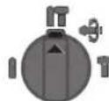
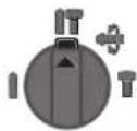
Position for hammer drilling in concrete or stone
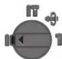
Position for drilling without impact in wood, metal, ceramic and plastic as well as for screwdriving
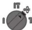
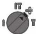
Vario-Lock position for adjustment of the chiselling position The mode selector switch 9 does not latch in this position.
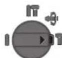
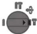
Position for chiselling
Reversing the rotational direction
The rotational direction switch 4 is used to reverse the rotational direction of the machine. However, this is not possible with the On/Off switch 6 actuated.
Right rotation: Turn the selector switch for drilling/hammer drilling 4 on both sides to the stop in the position


16|English
Left rotation: Turn the selector switch for drilling/ hammer drilling 4 on both sides to the stop in the position
Set the direction of rotation for hammer drilling, drilling and chiselling always to right rotation.
Switching On and Off
- To start the machine, press the On/Off switch 6.
- To lock the On/Off switch, keep it pressed and additionally push the lock-on button 5.
- To switch off the machine, release the On/Off switch 6. When the On/Off switch 6 is locked, press it first and then release it.
To save energy, only switch the power tool on when using it.
Setting the Speed/Impact Rate
The speed/impact rate of the switched on power tool can be variably adjusted, depending on how far the On/Off switch 6 is pressed.
Light pressure on the On/Off switch 6 results in low speed/impact rate. Further pressure on the switch increases the speed/impact rate.
Overload Clutch
If the tool insert becomes caught or jammed, the drive to the drill spindle is interrupted. Because of the forces that occur, always hold the power tool firmly with both hands and provide for a secure stance.
If the power tool jams, switch the machine off and loosen the tool insert. When switching the machine on with the drilling tool jammed, high reaction torques can occur.
Working Advice
Before any work on the machine itself, pull the mains plug.
Changing the Chiselling Position (Vario-Lock)
The chisel can be locked in 36 positions. In this manner, the optimum working position can be set for each application.
- Insert the chisel into the tool holder.
- Turn the mode selector switch 9 to the "Vario-Lock" position (see "Setting the operating mode", page 15).
- Turn the tool holder to the desired chiselling position.
- Turn the mode selector switch 9 to the "chiselling" position. The tool holder is now locked.
- For chiselling, set the rotation direction to right rotation.
Inserting Screwdriver Bits (see figure H)
Apply the power tool to the screw/nut only when it is switched off. Rotating tool inserts can slip off.
To work with screwdriver bits, a universal bit holder 22 with SDS-plus shank (accessory) is required.
Clean the shank end of the adapter shank and apply a light coat of grease.
- Insert the universal bit holder with a turning motion into the tool holder until it automatically locks.
- Check the locking effect by pulling the universal bit holder.
- Insert a screwdriver bit into the universal bit holder. Use only screwdriver bits that match the screw head.
- To remove the universal bit holder, pull the locking sleeve 3 toward the rear and remove the universal bit holder 22 out of the tool holder.
Maintenance and Service
Maintenance and Cleaning
Before any work on the machine itself, pull the mains plug.
For safe and proper working, always keep the machine and ventilation slots clean.
If the replacement of the supply cord is necessary, this has to be done by Bosch or an authorized Bosch service agent in order to avoid a safety hazard.
A damaged dust protection cap should be changed immediately. We recommend having this carried out by an after-sales service.
Clean the tool holder 1 each time after using.
After-sales Service and Application Service
Our after-sales service responds to your questions concerning maintenance and repair of your product as well as spare parts. Exploded views and information on spare parts can also be found under:
www.bosch-pt.com
Bosch's application service team will gladly answer questions concerning our products and their accessories.
In all correspondence and spare parts orders, please always include the 10-digit article number given on the nameplate of the product.
Great Britain
Robert Bosch Ltd. (B.S.C.)
P.O.Box 98
Broadwater Park
North Orbital Road
Denham
Uxbridge
UB95HJ
At www.bosch-pt.co.uk you can order spare parts or arrange the collection of a product in need of servicing or repair.
Tel. Service: (0344) 7360109
E-Mail: boschservicecentre@bosch.com
Ireland
Origo Ltd.
Unit 23 Magna Drive
Magna Business Park
City West
Dublin 24
Tel. Service: (01) 4666700
Fax: (01) 4666888


Francais | 17
Australia, New Zealand and Pacific Islands
Robert Bosch Australia Pty. Ltd.
Power Tools
Locked Bag 66
Clayton South VIC 3169
Customer Contact Center
Inside Australia:
Phone: (01300) 307044
Fax: (01300) 307045
Inside New Zealand:
Phone: (0800) 543353
Fax: (0800) 428570
Outside AU and NZ:
Phone: +61 395415555
www.bosch.com.au
Republic of South Africa
Customer service
Hotline: (011) 6519600
Gauteng - BSC Service Centre
35 Roper Street, New Centre
Johannesburg
Tel.: (011) 4939375
Fax: (011) 4930126
E-Mail: bsctools@icon.co.za
KZN - BSC Service Centre
Unit E, Almar Centre
143 Crompton Street
Pinetown
Tel.: (031) 7012120
Fax: (031) 7012446
E-Mail: bsc.dur@za.bosch.com
Western Cape - BSC Service Centre
Democracy Way, Prosperity Park
Milnerton
Tel.: (021) 5512577
Fax: (021) 5513223
E-Mail: bsc@zsd.co.za
Bosch Headquarters
Midrand, Gauteng
Tel.: (011) 6519600
Fax: (011) 6519880
E-Mail: rbsa-hq.pts@za.bosch.com
Disposal
The machine, accessories and packaging should be sorted for environmental-friendly recycling.
Do not dispose of power tools into household waste!
Only for EC countries:
According to the European Directive 2012/19/EU for Waste Electrical and Electronic Equipment and its implementation into national right, power tools that are no longer usable must be collected separately and disposed of in an environmentally correct manner.
Subject to change without notice.
Français
Robert Bosch (France) S.A.S.
= 0 = 0 = 0 = 0 = 0 = 0 = 0 = 0 = 0 = 0 = 0 = 0 = 0 = 0 = 0 = 0 = 0 = 0 = 0 = 0 = 0 = 0 = 0 = 0 = 0 = 0
Bosch Service Center
Telegrafvej 3
2750 Ballerup
Pä www.bosch-pt.dkkan der online bestilles resededele oeroprettes en reparations ordre.
TIf. Service Center: 44898855
Fax:44898755
E-Mail: vaerktoej@dk.bosch.com
Bortskaffelse
Bosch Service Center
Telegrafvej 3
2750 Ballerup
Danmark
Tel.: (08) 7501820 (inom Sverige)
Fax: (011) 187691
Avfallshantering
Endast for EU-lander:
Emloytookkaiepyaaleiwv
Tia to Tpuunma je kpoan kai yia to kaiauja xpeiaeote epyaia SDS-plus ta onla tonoetouvtai otoak SDS.
Tia tpuunmaxwipkpoouon oe Euha, mTaAka kaioe Kepaikakai natauka kao ckiy iia biu maata npenei va xnoiunoie Te epyaaleia wupic SDS-plus (n.x. tpunavia me kuivdpiko oIeXoc).Tia ta epyaleia auta xpeiaote n eva taxutook n eva ypavaawtook.
Alambdayn ypavacwou took
Ia va mnpoeote va epyaoteire peepaleia wopic SDS-plus (π.x. tounaviae kuAivbpiok oTeAexoc) npenei va ouvapiloyo nOe eva katalantooek (ypavaawtooakn taxutook, i6ikéApthmuata).
SuvapoloyonTou ypavaZtouTook (Bale Eikova C)
Biodote to tneXoc unoOxic SDS-plus 15 oe eva ypava zoTo Tock 14.AopalaTe to ypavaZto Tock 14e Tn Biia aopaleiac 13. Poooxh: n Biia aopaaieiac eivai apotepoatpoqn.
Apaipean Tou ypavaawou took
TonoBcTnO npyaleoiu xupic SDS-plus
Ynobei:Mx npaonoutae note epyaela xwipc SDS-plus yia trpunmae kpoan yia kaalemuajtae yaepaaeia wipc SDS-plus kal aavtoxa took kataoppeovtar otav npaonoiouvra iayrpnnae kpouon kal yia kalemuja.
- TOnoTheTne To ypavaZwTo Taok 14 (BAne «Aaayn YpavaZtou Took, oElaia 70).
AvoiETo ypavzto Took 14yupovtac to,muo poeae va tonoethoete to epyaleio. Tonoetne to epya
TOnoBETnTo KAEiDi Tou ToK OTC AvTiOToXe TpuNC Tou Took 14 Kai ophiTe To epyaleio yepa Ka omuOpoppa.
Tupiorto diakontnn aavoToaIcKpouoc/ncipoiotpohc90n Theon «Tpunmu.
Apaiaeconepyaaleiouxwopic SDS-plus
-Γuploe me to kaeiol Tou To Kekuoc Tou ypavaZtou Took 14 me popa avtietn Tc wpoLoyiaKic, mepvi va mtopoe aTe v apaipoeote To tonoetnevo epayelo.


EAnnvika171
Avappoyno e Saugfix (e16iko eApTmu)
Hokovn ano opiaeva uiká. n.x. ano oluubooxc μnoiyec, anepeika eton elou, ano opukta uiká kai ano metaal μnpoei va eliva avuyieivn. H enaqhe t n okvyn h/kai n eionvo ntc npoei va npokaleo aalpeyikec avtbpoeic h/kai aodoeveic tvavatnuotikw odov tov xphotn tuvxov napepuaikouevov atouwv.
Opiéva EIb oKovn, n.x. oKovn ano Euloo Bcavidiac n Ociac 0ewpoovta aav Kapivoyova, 1biairepa oe ouvdua ope biapopa oupamwpatika ukaou xnpaonoiuvtai npkatepyia 5uaw (evwaeicxpwuiou, Euonpoataeutikapeoa). H katepyia qauvouxuvukov emptene tai mvoce i6iKa cnaidemuva atota.
- Na xpnaiopoioteke ta to duvatioia to ekotote uuko Tnv katannan avappopnon.
- Na φροντιζετη γία τοῦ καλό σερερμό του χωρου εργαδιας.
-2acoumbouleoumevaopateaokecavantveoTnnpootadiaceipitpo karyopyiacP2.
Na Tnpelte TIC biataeic nou iXouov otxwpaac yia ta di apopa uno katepyoiduik.
Na anopeuyete n 6nmuoyia ouoowpuocokovnc oTO xpoTou epyzoe. Okovec avapayovtat ukoja.
Sigma oynou Saugfix eKova F
IaTnV aappoonO kovnc xpeiaeOe eva Saugfix (eiiok oEapna).OTav Tpunate To Saugfix omooxpei,Evw tauroxpova eva evomegaatupevo Eaatnpio nieCt Nv Kepaan Tou Saugfix opyra endv any enipaveia.
- Pnntote Tn nhtpo yia tn pueuion Baoouc 10 kai apaepote tov onnyo Baoouc 11. Pnntote naTto nAiktpo 10 katoonetne To Saugf anpooa otyn npoeTn AaBn 12.
- Suovboge eva oawhva avappoqnonc (pe 6iauetpo 19 mm, eioiko eaoptma) oto avoiya avappoqnonc 16 tou Saugfix.
O anopponpnapocovnpene va evai kataknloycia to ekatoe unokatepyaia uko.
IaTn avappoon 1diatepa aovuyieivnc, kapkivoyovou nE npC oKovnc npeneva xnpaunoeite eikouc anoppopnntpec okovnc.
Pouon Tou boudoc konic o Saugfix (Bene cikova G)
Mnpelte va puOlaeTo enoUunTo Baooc TpuHmuoc X enI onk kalto auvaupoaoynevo Saugfix.
- Ωθησετο εργαλείο SDS-plus τέρμα στήν Αυόβχι ἡργαλείου SDS-plus 1. Διαφορετικάν κινητικότητα του εργαλείου SDS-plus μηρείν αὐδηγλείοε λαθος υμιαίου ταβθους τρυπματος.
- Aoure t n Biδa μe μoXlo 20 σto Saugfix.
TOno0eHTnTo nAekptko epyaaleio, xwpc va to teocet nponyouevwc oEletoupyia, yepa enawv otn 0ean nou cte va tpuinoe. To tono0eTnevo epyaaleio SDS-plus npenei va akouumnncenewv ony enupeveia.
Metaroniote to oawlya odnyonc 21 tou Saugfix meoa oto ouykpatnpa tou, pexpnkepaan Tou Saugfix va akoumuaei enav otynenapaveia nou npoketra vtpunoe. Mny othoete to oawlya odnyonc 21 napanv w an ooo npenei eawantoovtnleakonikoowhya 19,yia va napapeiveopa
To eavw oov Tnaeokoniko oAwnv 19 eva 0o to duvat mio eyautepo koupat nKaijakac.
ZpIeTnaiKaTa nBlaaPeOxAo 20.AuTe nBlaaoukpaTmng17oovOnyoBaoucTou Saugfix.
MetatonioteTovobnyoBaouc18enawotnleokonok oAlyva19,07e n anotaonXnoudeiyvetaiOnvEikova vaavtoiyeiotoeimtoumToBaoctpunmuoc.
Pouan ap0oouotpovkpooew
Mnpoei va puioaetov apioo otpoov/kpuoewtou e uio koiuevou o aeitouyia nkeptkoepyaaiou adiaobuota, avaloyaeynieonnou aokote stiaoknt ON/OFF 6
Elaepia nion tou diakontn ON/OFF 6 exo av anotaeqa μkpni auenan Tou apiou oTpoov/Kpouoev. O apiOuc oTpoov/Kpouoew auavieu e auenan tnc nieon tou diakontn.
EuMaektnc unepopropns
nepintwnou to Eaaptma opynwoei npooopouoai kano, diakontetai n metadoon kivnnc otov dova. Na Kpatate, loyw twv epaaviocveov duvaewv, to naektpko epyaaleia kala kal a ta duo oac xepia kal va naipvete me to ouaa oac staepepn otan.
Otav mlokapei to nektpko epyaieo ote to kctoc aeitoupyia kai Auote to tonoBetnueo epyaieio. OtaV te to nektpko epyaieio oe aeitoupyia µ mlokapiouevo to epyaieio tounmuato cngnioupyovutai uxupec avtbpaoitrkcsdvuaic (klotanjata).
YnobeiEicepyaiaC
ByaCte to qic ano tv npia npiv ano onoiadnote epyaia oto nAekptko epyaleio.
AALLayntgEoCkalemuou(Vario-Lock)
Mnpetve va pavbaawoe to kaiepe 36 0ec. Eto npepte v npae Tnv kalute np duvat th eon epyaiaac.
TonoTeHnToKaAeUOTNV unOdox npyaleiou.
-FuploTe To diaKoTm KPOUcN/NEPIOTpOPhC 9 Otn ΘeAn «Vario-Lock》(βλεπ«Puθμιαn Tou TpONou λεIToupyiaq, αελiδa 71).
-Γuipote TnV uno6xH epyaaleiou otny eniount h eon kaiemuou.
TupioTe to diakontn avatoanck kpoaun/npiopp9 0n Theon Kalemuia).Era mavdaowve n unofox npepyaleiou.
-Γa to kaλeμασεια Ειλεξτε δεξιοτρορη κινηση.
TOnoTeHnKarouaBolaouov(BeneEkovaH)
NaBaTeTo nAeKtpko epyaleio enawv otn Bida/To naEiayo mOvo otav auto Bpiaketai kTcOc Ateoupyia. Peipotpepoeva epyaleia mOpel va yAtoqouov.
Tia va unopoee va xpanoioane tic kataaaibolaue cxieae eva oukykpatna yevikxphonc 22 me talexcoc utoboxh SDS-plus (eiiko eapntma).
- Na kaθaipεte kal va λιανεte ελαφρa tó ἀκρο του οτελέχους Ανόβαχος τοῦ μανείνοτο γραναζωτό τοῦκ.
ToTOnOeTnOte To ouyKpAtnpa YeviKcXphnC, yupizovrTa Tov, atnv unOboxH epyaaleiou pexpi va pavdaawoei ano moVoc Tou.
-EAeEETn mavdaawon me rpaBnya tou oukypatnpa yviKNCXPnOnc.
Tonothe nTv katoaBdoLama oTo ouyKpIpa yevikn Xpnnc. Na xnpouonoeite mOvo katoaBdoLape cou taipacov otic kepaLcTw avtatoiwy BiWv.
-1a va aapieoete to aukykpatna yevikncxpnongwto To kakuoc mavdaawon 3 npoc ta naw kal apiaipote to auykpatna yevikncxpnong 22.
Euvtnponk kal Service
Luvtnpnonkkaqapiaooc
ByaCteTo oic ano nV npia npv ano onoiabnote epyaia oTnAekptko epyaieio.
atrnpeiteTo nAektpko epyaleio kai Tc oxiauec aepi oou kaopacvva unopeite va epyaceoKe kalakai aophaaoc.
Mia tuxov avaykaia avikataaon tou nAekptko kALomega npenei va dieaxtheta ano tv Bosch h ano eva eouoiobotmevo katantma Service Tc Bosch, yva anopexutheta etatkbe dtakivduveuon tnc aopaleiac.
Evxaaoepo kaumu npoataiaac ao oxov npenei vaavkathetaataa aoeoc.aaoubetaououpe,navtikaraon va dieayetai an to Service.
NaKaθaipZeTe TnV unOboxH epyaaleiou 1 peta ano Kaθe xpn. onTnc.
Service kal npoxn oupoulovxphons
To Service anavra otic epwntnoe oac oxetika me tny eniokue n kal tn ouvtnpnou npoiovoc aac kaohc yia ta kataaanaa avtalaaktka: www.bosch-pt.com
H ouda npaoxnc ouuouovn Bosch anavra euxapiotoc otc epwntnoeic oac oxetikae ta npoiovta mac kai avtalakktikouc.
AOTe OE AEC TIC EPWTHOEIC KAI NAPAYEAIEC AVTAAAKTKOV OTWbHnote TO 10yphio KwBIO apiO OUPOWa ME TNY IVAKIa Ttou Tou PoiovTOc.
EAAaδa
Robert Bosch A.E.
Epxieic 37
19400Kopmi-Ahya
Tnλ.:2105701258
Φaξ:2105701283
www.bosch.com
www.bosch-pt.gr
ABZ Service A.E.
Tnλ:2105701380
Φaξ:2105701607
Türkçel 73
Anoupon
Ta nlektpka epyaia, ta eapntmuata kai ooukeuaacc npenei va avakukawovtai pe tpofo iikno poc to ppiBaalov.
Mny pixvete ta nlektpka epyaia ota anoppmuata tou onitouoac!
Movi yia xwpec tnc EE:
Uuwpva u e Tn Koovtki Onyia
2012/19/EE oxetika u tic naalec nkepti Kec kai nkeptpvikc ouakeuckac ktn meta-
popa tnc ondyac autnc oe eviko diko av
eivai neov unoxpewto ta axpnota nkepti Ka epyaia va auyyovta Exxwpia yia va
avakukawoov u pono pfiko npoc to nepi
baalov.
Tnpoue to 6ikalwa aaiayov.
Türkce
Güvenlik Talimati
Elektrikli El Aletleri icin Genel Uyar Talimati
UYARI
SDS-plus'suz ucin cikarilmasi
Robert Bosch Sp. z o.o.
Cpok Cnyk6bI H3dEHHncoCTabHnet 7 net. He peKoMeHdyetcK 3KcNpyataun no HcTeueHHn 5 net xpaHeHH nTaTbI n3rOToBnEHn 6e3 npedBaHPtehHO npOBepKn (aTy n3rTOBnEHn CM. Ha 3TNKeTke).
IpeuehB KpHTnueckHX OTka3OB N OwH6OuHbIe DeHCTBnepcoHana Hnn Nnbl3OBaTeN
-HeHCIOB3OBAbC NOBpeKDeHHo pyKOaTkoHnNIOBpeXDEHHbIM 3aUHTbIM KOxyXOM
-HeHCIOJIb3OBA Tb Pn IOIeHN IbIMa HINOCpeCTBeHHOI3KOpNycaH3dEINr
-HeHCIOJIb3OBaTbCIIpe6HTbIM HIN OOrIeHHbIM 3JIeKTPNueCKM KaBeEM
-HeHCIOJIb3OBAbHaOTKpbITOMIPOCTpaHCTBeBOBpEmdoXn(BpacblJREMOBDE)
-He BkIIOuA Tb pH NOnaHaHH BObl B KOpNyc
-HeHCNOB30BAbTINPHCNbHOMNCKpeHHN
-HeHCnOJb3oBaTbPnNIOBAnEHINCNJbHOHBN6paun
Kpntepnn npedenbhbix cctoHH
- npeTepn NIOBpeXdEh 3neKtpueeckn KaebIb
-NOBpeKdEN KOpNc H3eJIIN
THHn nepnouhoctb texhueckoro 06cnyxhaHH
PekomehnyetcOuHCTnTBHHCTpyMeHTOTbINNOCNEKaXdo-TOHCNOB3OBAHNA.
XpaHHeHne
-Heo6xOJHMO XpaHHTb B CyXOM MeCTe
-Heo6xOJIMO XpaHbTB BdAnOT NCTOuyHKOB NOBblweHHbIX
TEMnepaTpH BO3dEChTBnCOnHehBxIyuei
- npxpaHEnH Heo6xoHMo H36eRaTb pe3KOro nepenada TeMnepaTp
-xpaheHHe 6e3 ynaKOBKn He donyckaetc
-nopob6HbIe Tpe6oBaHHa K yCIOBnM XpaHeHHa CMOtPHTe BTOCT 15150 (yCNOBne 1)
TpaHcnpTnpoBka
Kateropnueckn He donyckaetca naeHne HIOb6e MexaHnueckne BO3deCTBna HA ynaKOBky npu TpaHCnpTHPOBKe
- npn pa3rpy3ke/nporpy3ke He donyckaetc HcnoIb30BaHne IIO6oOBVaTeXHnK,pa6OtaUoSeIIO npnHnny3aKHMaynaKOBKn
- noDpObHbIe Tpe6oBaHnK YcIOBnAM TpaHCnOpTHPOBKn CMOTPHTBFOCT15150(YcNOBHe5)
Yka3aHnno 6e3onachoctn
06une yka3aHnno TexHnke 6e3onacHOCTn nna 3NeKtpOHnCtpymENTOB

IPOUHTHe Bce yka3aHHN HNCTpyKuHn No TEHXnke
6e30nachocTH. HecobnOdeHne yka3aHH nHnCTpykui nToTexnke 6e30nachocTH MOKeT cTaB npuHHo nopaxHeHn3JeKTPnueckHM TOKOM, NOkapa N TpKaJIbIX TpaBM.
CoxpaHnIe 3TH HnCTpyKuHH yKa3aHnN dnn 6yduero HCNoB3OBAHn.
NcnoB3oBAHHe B HactOaHx HnCTpyKuHx NyKa3AHx NOHTHE 3eNEKtponHCTpymEtPacPiocptpaHreTc Ha 3eKTPoHNCTpymEtC nHaHemOT cTu (C CteBbIM WHypOM) HA aKKyMnIaTOPbHn 3eKtponHCTpymEt (6e3 cTeBorO shypa).
Be3onachoctb pa6oeryo MecTa
CoepKHTpepaOooMeTcBmCToteHxopo0ocBeHueHHbIM.BecnpaOKnHHeOCBeHHeyactKn pa6oero MeCTaMOrT npVBcTn K HeCuaTbIM CnyaAM.
He pa6oTaTe C 3TNM 3NEKTPONHCTPymeHTOM BO B3pblBOOaNCHOM NOMEUeHH, B KOTOPM HAXODTc FIOUOy HE NKoCTn, BOCnMaHEHOUeHcR Ta3bl Hn Nbl.3NEKTPONHCTPymeHTb HCKpT, yTO MOKeT PnHBecT K BOCnMaHEHIO NbIIN Nn napOB.
Bo Bpempa6oTbC3NeKtpOnHCTpyMeHTOM He donyckaIe 6n3KO BaWemy pa6oemy MeCTy DetEn HocToPOHHNx NtU. OTBNeKUnCb, Bbl MoKeTe NoTePrtb KOHTPONBnAD 3NeKtpOnHCTpyMeHTOM.
3neKtpo6e3onacHocTb
WtencnbHnBnka 3neKtpOHcTpymenta DonxHa noDxOdbK WtencbHno p03eTke. Hn B Koem cnyae He hmeHnre WtencbHyo Bnky. He npmeHnre nepexodhble WtKepbI dN 3neKtpOHcTpymetOB C 3aunTHbIM 3a3emHeHm. HeIm3MeHeHHbe WtencbHb BnKn nOxOdaIue WtencbHbpe p03eTK CNXaOT PNCK NopaxEHnH 3neKTPOTOKOM.
PpeoTbpaaaTeTeeChbIK KOHTAKTC 3a3emHeHHbIMN NOBepxHOCTHM, KAK TO: Ctpy6aMn, 3neMeHTAMN OTOHNNK, KYXOHbIMN NHTAMN XOIOHNbHKAMN. Pn3a3eMNEHN BaWero Tena nobbIaAetc pck npaKeHHaNEKTPOTOKOM.
3aunuaiTe 3eKTPoHHCTPymENT OTdoxHn CbipocTH. POnHHKOHeHne BOBb B3eKTPoHHCTPymENT NOBbIaet Pnck npaxehna 3eKTPoTOkOM.
He pa3pewaaetca HcnoIb3oBaTb Whyp He no Ha3haeHHIO, HanpHMeP, IIN TpaHCnOpTHPOBKN Hnn NOBBeCKN 3NEKTPOHNCTPYMEnTA, HNN DnA BbITrHBAHNA BNIKN H3 WtencenBHOH PO3eTK. 3aunuae TWhpy OTOBdEHTBnB bICOKHX TMnePaTpy, Macna, OCTpbIX KPMOK HIN NOBHNbXb Xacte 3NEKTPOHNCTPYMEnTA. NobpeJxDEHHBI INN CNyTaHHBI WHyp NOBbIAe PnCK NopaeHHRA 3NEKTPOTOKOM.
Pnpaobote c3neKtpoHCTpyMeHToM NOOTkpblbIM He60npmehnTe nproDhble Ira 3TOrKa6eHN-yd HnHTEN. PpmeHHe NpRHOHorO Ipa60bI NOIOT


Pycckn103
KpbTbIM He6om Ka6eIy-dnHHTenr ChnXkaet Pnck npa-KeHH3neKtpoTOKOM.
EcnH HeBO3MOXHO H6ExKaTb PnHMEnHeHn 3NeKtpOnH-CTpymEtA B cbIpOM NOMEuEHn, NOkKnUoHaTe 3NeK-TPOHCTpymEt Ype3 yCTpoNCTBO 3aunTHOrO 0TKIOueHH. PnHMEnHeHn yCTPOINCTBa 3auNTHOrO 0TKIOueHH CHnKaET PNCK 3NeKtpueckoro NOPaKeHH.
Be3oNaChocThnOdei
ByBnTe BHHMaTeNbHbIMN, cneHnte 3a Tem, qTo Bbl Daete, H npOyMaHNo HaHnHaTe pa6Ory C nEKeTPOHnCTpyEMTO. He NOnb3yntEcB nEKeTPOHnCTpyEMTO B yCTaON COCToAHnn Hn Ecln Bbl HaxoHTecB B CoCToAHn HapKOTHeCKOrn AnkoROnhOro ONbHReHN Hn ND Bo3dEChTBm NekapCTB. OINMOMeHT HeBnHMateBnHOCTn PnH pa6Ote C nEKeTPOHnCTpyEMTO MOKET PPNECTN K cepE3HbIM TpaBMam.
PnmeHnte CpeCTBa HnBHyAynbHO 3aunbI Bcerga 3aunthbe Ock. NcnoB3OBaHne CpeCTB HnHnBdyAynbHO 3aunbTb, KAK TO: 3aunTHO MaCK, OByHnHeCKoNb3aJeep NOIOwBE, 3aunTHO Ro IJema HnI cpeCTB 3aunbI opraHO Cnyxa, -B 3aBNCmOCTN OT BHa paBoTbC 3NeKtponHTpymEtOM ChnXaet Pnck NOnyehn TpaBM.
PpeoTbpaaaHHe nppeHaMeepenHoe BkIoueHne 3NEKTPOHNCTPymeHa. Peep noKIOUeHnem 3NEKTPOHNCTPymeHa K 3NEKTPONHTAHNO H/nnn K aKKyMnyTOpTy 6yeDntecB BbIKIOueHHom COCTOHHN 3NEKTPOHNCTPymeHa.YpeKaHne NaIbua Ha BbIKIOuata TEne Ipn TpaHCnOpTPOBKe 3NEKTPOHNCTPymeHa N oND KIOUeHne K CETn NITAHNA BKBIOUeHHOrO 3NEKTPOHNCTPymeHa YpeBaTO HeCuaCTHBIM CNyAaMn.
y6npaTe yCTaHOBOHyH NHTpyMeT HnraeYhBle KIOUOn Do BKNIOUeHH 3NEKTOPOHCTpyMeHa. INCTpyMENT HIN KIOU, HAXOJUNHC BO BpauOJIeC aCTN 3NEKTOPOHCTpyMeHa, MOKeT PnBeCTN KTPaBMAM.
He npHmMaTe HeecTcBHeHoe NOIOKeHne KOpnyca Tena.Bcerda3aHmMaTe yctOuHBOe NIOOKeHne H coXpaHnTe paBHOBecne.5naorapA 3OMy BblMOKeTe lyUwe KOHTpOINPOBaTb 3NeKtpOnHCTpyMeHT BHeoxKnDaH HBIX CNTyaunx.
Hochtne noxdxodnypo6oyu odekny. He hochte shpokyo odekny ukypaewnna. DepeKHTe BONocbl, odekny npykabnbl BdAn OT ABKyuuxcyaCTei. shpokar odekda,ykpaewnna nn DnHHbIe BOLOcbl MOrtyt bItb 3aTaNbIb BpaauounmncyactmH.
PnHannuHBO3MOXHOCTyCTAHOBKNbIeOTcAbBaIOUxNbIeNc6OpHBxYCTPOBCTNpOBepeHTNpncoeHNHeHnnpaBnHbOEHCNOb3OBaHne.PnMeHeHn PbIEoTcOCA MOKET CHN3NTb ONaCHOCTb,Co3DaBaemyIO bIbIO.
PpmeHne 3nEeKtpoHHcTpyMeHTa n6paueHne c HMM
He neperepykaite 3neKtpOHCTpymEn. Hcnonb3yte DnBaew pa6oBtI npedHa3NaueHHbI DnA3TORE NektpOHCTpymEn.CnoxOdaHIM 3neKtpOHCTpyMeHTOM Bby pa6oTaTe Iyue He naexHee Byka3aHHOM dHaana3OHe MoUHocTn.
He pa6oTaIe C3NeKtpOnHCTpymEtOM npn HeHcnpaB-HOM BbIKNoHTeNE.3NeKtpONHCTpyMeHT, KOTOpbI He NODJaTcBAKIOUeHHIO IIN BbIKIOUeHHIO, ONaceH IOJKeH 6bITb OTPMOHTPOBaH.
Dohauana Hanaikn 3neKtpOnHCTpyMeHTa,nepe 3aMeHOH npHaadNkHoCTe H npeKpaueHem pa60tIOTKNIOHaeTHTe WTeNCbHyBOBNIky OPO3eTKCNTHN BbHBe aKKymyTAOp.3a Mepa npedoc-TOPOXHOCTn PpeoTbPaAet HnpeDHaMepeHHoe BKIOUeHNHe 3NEKTPOnHCTpyMeHTa.
XpaHHe 3NEKtpOHnHCTpyMeHTbB HeOCTyNHOMdIaI DeTeMecTe. He pa3peWaiTe NOnb3OBaTbC8 3NEKtpOHNCTpyMeHTOM HnCaM, KOTOpBie He 3HaKOMbl C Hm HnHe HHTaHn HAcToaHxHnCTpyKu. 3NeKtpOHNCTpyMeHTb ONaChb B pyKaX HeONbTHbIXnL.
TuaTeNbHO yXaXHbAte 3a 3neKtpOHCTpyMeHTOM. PObBepaIte 6e3ynpueHyO fYHKUIO H XOD ABHXyUxxCra Yacte 3neKTPoHNCTpyMeHTA,OTCYCTBE NOmOK HIN NOBpExKeHn, OTRuCaTeNbHO BnHIOUX Ha FynKUIO 3neKTPoHNCTpyMeHTA. NOBpeKdEHbIe YaCTN DOJXHbI 6bITb OTpeMOHTPOBaHbI Do HcNoJIb30BaHn 3neKTPoHNCTpyMeHTA. IINOxoE 6cIyKbAHHe 3neKTPoHNCTpyMeHTOB RblTeC TpNHHO BoIbWo YoNCla HeCyaCTHBx CNYaEB.
DePKHTe pexyHn HNCTpymEt B 3aTOueHHom nH CTOM COCTOHN. 3a6oTINBO yXoKeHHbIe pexyuHne HNCTpymEtBcOCPTbIMn pexuyuHm KpOMKaMnpeXe 3aKNHNBaOTc NIX NJIeYBeCTn.
PpHmEHTe3NEKtpOHnCTpyMeHT,INHHaIeXHoCTM, paOoHne HnCTpyMeHTbH T.I.B COOTBeTcBHN C HAcTOH MMn HnCTpyKzHM.N.YuTHbBaHTe pNtOM paOboye ycNoBH N BblONnREmyo paOby. IcnoJIb3OBaHHe 3NEKtpOHnCTpyMeHTOB DnHeppeyCMOTpeHHbIX paOTo MOKeT PpNBecT K ONaChbIM CHTyaUHM.
CepBnC
Pemont Baawero 3eKtpOHCTpymHtA npuyaTe TOnbKO KBAHNHcHPOBaHHOMy nepcoHany nToBko C npHMeHenHem opnHHanhblhix 3anaChbIX qacte.3THM obecneuHbaetcBe3oNaCHocb 3eKTPOHCTpymHeTA.
Yka3aHnno TExHnke 6e3onacHocTH nI npOpaTopoB
PnmeHHe CpeCTBa 3aunhtb opraHOB cnlyxa.Bo3- DeCTBne UyMa MoKet PnpBeCTN Knotepe cnlyxa.
Ponb3yTeCb DOONHHTeBbHM pyKoTkAMn, BxOaIIMM BOBem IOCTABKN 3NeKTPOHHCTpymenta. NToepa KOHTPOIA MOKET PINBEcTH K TENECHBMIOBpeXJeHNRM.
PnBbINONHeHH pa6OT, pN KOTOpBX pa6Oun HnCTpyMeH nH Wypyn MoKet 3aDeT bCKpIyTO 3NeKToPO npBOky CO6TBeHHb Whyp NTaHn, DePxxTe 3NeKToPHNCTpyMeTH 3aONIOPAOBAHbE pyKy. KOHT C haoJrueeC NOd HapRJaEHm PNOBoDkoMooKet 3apXKaTb MeTaNIMueckne AcTH 3NeKToPHNCTpyMeHT A IN PnBOHNTb K yDAPy 3NeKTPnueeCKHM TOKOM.
HcnoIb3yIe coOTBETCTBYIOUHe MetaONNCKATEIN DnHaxoXdEHH CNpTaHbIX BCTHe Tpy6 HnnpoB0DKHnHnObaPaaTecb 3a CnpAKBOn B MeCTHOKm


104|Pycckn
MyHaIbHoe npEepnpyTHe. KOHTaKTc3JKeTPOnpoBOkO MoKET npBBeCTN K NOKApuy N nopaxeHHO 3JKeTPOTOKOM. IIOBpeJdHeNe ra3OpPobOda MoKET npBBeCTN K B3pblBy. IIOBpeJdHeNe BOJOpPobOda BeET K HaHeceHHo MaTePNaIbHO rUepeBa Hn MoKet BblBaTb NopaxeHHe 3JKeTPOTOKOM.
Bcerdaepxhte3neKtpoHcTpyMeHT BO Bpempa60 TbI 6eHNM pykAMn,3aHb IpeDbapHTenbHO yCTOuHBOE noOnxHeH.1ByMa pykAMn Bbl pa6oTaete 6oJee HaeJHo C3neKtpoHcTpyMeHTom.
3akpennne 3arotOBky.3arotOBka,yctahOBneHHAB 3axmHoe npncnoc6bnHe HnB TtCKN, ydepXnBaetc 6oee haeKHO, yem B Baew pyke.
BbIXnTe NONHO OCTAHOBKN 3NEKTPOHNCTPymeHTa TOnbko nocne 3TOro BbInyckaIte erO h3 pyk. Pa6ouH INCHPTpMeHT MOKeT 3aeCTb, H 3TO MOKeT pINBecTn K NOTepe KOHTPOJHaD 3NEKTPOHNCTPymeHTOM.
Onncahne npodykra n ycnyr

IpoHTe Bce yka3aHn HnHCTpyKuHn No texHnke 6e3oNaChocTH. YnyueHHB OTOHOWeHHyka3aHn HnHCTpyKuHn NO TexHnke 6e3oNaChocTH MOrY CTaTb npuHHo NopaKeHHa 3NeKTPueCKM TOKOM, NOxapa n TaKeBix TpaBM.
Ponayncta,OTKpoTepackndhycTpaHcycnHIOCTpA mN3eKtponHcTpymEnHaNocTabnIte ee OKpbToi, NOKa Bb H3yaeTe pykOBoCTBO No kCnnyatauH.
PpMHMeHHeNoHa3NaeHHo
3NeKtpOnHCTpyMeT npeHa3haeH dIydpHoro CBepHe HNtOBepCTn B6eTOE,KnPnHuax H npnpOHom KAMHe, aTaKkeDnIeRkXnDoB6ExhBxpaBOT. OH TaKke npriOdeH DnI CBepENHOro TBOPCTn 6e3 ydpHoro DeCTBnB IpBeBecnHe, MeTaNIIe,KePAmIKe N CHTeTHuecknx MaTepnAnax.3NeKtpONHCTpyMeTbC 3NeKtpOnHHbIM peryInpObaHem HpeBepcom HApBaJIeHNr BpaUeHNr pIroHObl TaKke DnI 3aBHNuBAH HINr BHITOB.
H306paXeHHbIe coCTaBbIe qactn
HymepaunnpnepctabNEHHbIXKOMNOHETOB BblONHeHaIO H3o6paKeHNHO CTpaHnue CnnIOCTpaHnM.
1 NpToPbSDS-plus
2KoNaqOKJn3aunTbOTnb
3ФИССИРУЮДАгИЛБЗA
4IpeeknouateIb HanpaBneHn BpauneHH
5 KhoNkaФнКсИрOBaHHa BbIKHIOuTeJIa
6 BbiknouateIb
7PyKoTka(cH3OJIHOBAAHHOIIOBExPOCTbIO
8 KhoIpa36nokpOBKn BbIKNoaTeYdapa/ocTaHOBaBpaueHn
9 BbiknouateIb yapa/ocTaHOBaBpaueHIN
10 Khonka orpaHnHTeIra Iy6HbI
11OrpaHnHtEnIy6HbI
12 DOnonHnTeBHa pyKoTka (Cn30nnpoBaHHo nOBepXHOCTbO)
13IpeoXpaHntBbHbINBHTCBepnHbHO natpoHa C 3y6aTbIMBEHcOM
14 CbePnIbHbI NaTPOH C3y6aTbIM BEHcOm
15 PocaochbXBOCTOBK SDS-plus CbeplnbHoro naTPOHa
16 OTBepCTHe OTCaCbIbAHn Saugfix
173axmmHOBuHT Saugfix
18 OrpanuHnTEnI rnybHb Saugf
19 TeneckonHueckanTpyba Saugfix
20 BapaKoBbI BnHT Saugf*
21 HanpaBnaIouaTpy6a SaugFix
22 YHnBepcAnbHbI DepeKaTeNb c XBOCTOBHKOM KpeNHeHHa SDS-plus*
H#o6paXeHbIe HnOONcHbIe pNnHaNDexKHOCTH He BXoT BCTaHapTbHb Oobem NoctBaKTN. HonNb accoTHMeHT pNnHaNDexKHOCTHe Bb HauNdete B Haueh nporpAmpe pNnHaNDexKHOCTe.
TexHHueckne daHHbe
| Перфоратов GBH 2400 | ||
| Товарный № | 0611 253 8.. | |
| Рergулироваиме чисla oboprotoь | ● | |
| Бл_OKирobва вразменя | ● | |
| Пробов/левонаправлиения вразменя | ● | |
| Hom. постбдема мочиость | Вт | 7 |
| Часло у导航ов | MHN-1 | 0-4000 |
| Сида оданоч然是 уда в сответсг�� СЕТА-Procedure 05/2009 | Дж | 2 |
| Часло oboproтоь | MHN-1 | 0-900 |
| Патраон | SDS-plus | |
| Даматушийнишпindеля | MM 50 | |
| Дамату OTberстя (мakс.)В: -бетонe | MM | 24 |
| - Крип ч咸阳 Калдкe (сокль-цево hyробч коронко) | MM | 68 |
| - стаи | MM | 13 |
| - древсанe | MM | 30 |
| Вес corласно EPTA-Procedure 01:2014 | Кr | 2,7 |
| Клascашиты | ☐ /☐ | |
| Паматулы уразалыддя Номиналь�оги наравоженя [U] 230 B. Рdn dpr'tхз зачених наравоженя, a тадж e сileцчдесkomддястра-hыInsолпени Инстру金融市场 BOЗмочны иные памату. | ||
| Данные пошую и вибрацinn 3начени звковая EmCSSСОпедени b COOTВETСВИС CEN60745-2-6. A-BЗveшени hyрobөн hyрobөн hyрobөн hyрobөн hyрobөн hyрobөн hyрobөн hyрobөн hyрobөн hyрobөн hyрobөн hyрobөн hyрobөн hyрobөн hyрobөн hyрobөн hyрobөн hyрobөн hyрobөн hyрobөн hyрobөn hyрobөн hyрobөн hyрobөн hyрobөн hyрobөн hyрobөн hyрobөн hyрobөн hyрobөн hyрobөн hyрobөн hyрobөн hyрobөн hyрobөн hyрobөн hyрobөн hyрobөн hyрobөн hyрobөн hyрobө网 hyрobө网 hyрobө网 hyрobө网 hyрobө网 hyрobө网 hyрobө网 hyрobө网 hyрobө网 hyрobө网 hyрobө网 hyрobө网 hyрobө网 hyрobө网 hyрobө网 hyрobө网 hyрobө网 hyрobө网 hyрobө网 hyрobө网 hyрobө net hyрobө net hyрobө net hyрobө net hyрobө net hyрobө net hyрobө net hyрobө net hyрobө net hyрobө net hyрobө net hyрobө net hyрobө net hyрobө net hyрobө net hyрobө net hyрobө net hyрobө net hyрobө net hyрobө net hyрobө.net hyрobө net hyрobө net hyрobө net hyрobө net hyрobө net hyрobө net hyрobө net hyрobө net hyрobө net hyрobө net hyрobө net hyрobө net hyрobө net hyрobө net hyрobө net hyрobө net hyрobө net hyрobө net hyрobө net hyрobөnet hyрobө net hyрobө net hyрobө net hyрobө net hyрobө net hyрobө net hyрobө net hyрobө net hyрobө net hyрobө net hyрobө net hyрobө net hyрobө net hyрobө net hyрobө net hyрobө net hyрobө net hyрobө net hyрobө net hyрobө nets hyрobө net hyрobө net hyрobө net hyрobө net hyрobө net hyрobө net hyрobө net hyрobө net hyрobө net hyрobө net hyрobө net hyрobө net hyрobө net hyрobө net hyрobө net hyрobө net hyрobө net hyрobө net hyрobө net hyрobөNet hyрobө net hyрobө net hyрobө net hyрobө net hyрobө net hyрobө net hyрobө net hyрobө net hyрobө net hyрobө net hyрobө net hyрobө net hyрobө net hyрobө net hyрobө net hyрobө net hyрobө net hyрobө net hyрobө net hyрobө Net hyрobө net hyрobө net hyрobө net hyрobө net hyрobө net hyрobө net hyрobө net hyрobө net hyрobө net hyрobө net hyрobө net hyрobө net hyрobө net hyрobө net hyрobө net hyрobө net hyрobө net hyрobө net hyрobө net hyрobө Nets hyрobө net hyрobө net hyрobө net hyрobө net hyрobө net hyрobө net hyрobө net hyрobө net hyрobө net hyрobө net hyрobө net hyрobө net hyрobө net hyрobө net hyрobө net hyрobө net hyрobө net hyрobө net hyрobө net hyрobө.Net hyрobө net hyрobө net hyрobө net hyрobө net hyрobө net hyрobө net hyрobө net hyрobө net hyрobө net hyрobө net hyрobө net hyрobө net hyрobө net hyрobө net hyрobө net hyрobө net hyрobө net hyрobө net hyрobө net hyрobө NET hyрobө net hyрobө net hyрobө net hyрobө net hyрobө net hyрobө net hyрobө net hyрobө net hyрobө net hyрobө net hyрobө net hyрobө net hyрobө net hyрobө net hyрobө net hyрobө net hyрobө net hyрobө net hyрobө net hyрobөNET hyрobө net hyрobө net hyрobө net hyрobө net hyрobө net hyрobө net hyрobө net hyрobө net hyрobө net hyрobө net hyрobө net hyрobө net hyрobө net hyрobө net hyрobө net hyрobө net hyрobө net hyрobө net hyрobө net hyрobө-net hyрobө net hyрobө net hyрobө net hyрobө net hyрobө net hyрobө net hyрobө net hyрobө net hyрobө net hyрobө net hyрobө net hyрobө net hyрobө net hyрobө net hyрobө net hyрobө net hyрobө net hyрobө net hyрobө net hyрobө NT hyрobө net hyрobө net hyрobө net hyрobө net hyрobө net hyрobө net hyрobө net hyрobө net hyрobө net hyрobө net hyрobө net hyрobө net hyрobө net hyрobө net hyрobө net hyрobө net hyрobө net hyрobө net hyрobө net hyрobөNT hyрobө net hyрobө net hyрobө net hyрobө net hyрobө net hyрobө net hyрobө net hyрobө net hyрobө net hyрobө net hyрobө net hyрobө net hyрobө net hyрobө net hyрobө net hyрobө net hyрobө net hyрobө net hyрobө net hyрobө NG HYPOLYCHINCHINCHINCHINCHINCHINCHINCHINCHINCHINCHINCHINCHINCHINCHINCHINCHINCHINCHINCHINCHINCHINCHINCHINCHINCHINCHINCHINCHINCHINCHINCHINCHINCHINCHINCHINCHINCHINCHINCHINCHINCHINCHINCHINCHINCHINCHINCHINCHINCHINCH INCHINCHINCHINCHINCHINCHINCHINCHINCHINCHINCHINCHINCHINCHINCHINCHINCHINCHINCHINCHINCHINCHINCHINCHINCHINCHINCHINCHINCHINCHINCHINCHINCHINCHINCHINCHINCHINCHINCHINCHINCHINCHINCHINCHINCHINCHINCHINCHINCHINCHInCHINCHINCHINCHINCHINCHINCHINCHINCHINCHINCHINCHINCHINCHINCHINCHINCHINCHINCHINCHINCHINCHINCHINCHINCHINCHINCHINCHINCHINCHINCHINCHINCHINCHINCHINCHINCHINCHINCHINCHINCHINCHINCHINCHINCHINCHINCHINCHINCHINCHIHNCHINCHINCHINCHINCHINCHINCHINCHINCHINCHINCHINCHINCHINCHINCHINCHINCHINCHINCHINCHINCHINCHINCHINCHINCHINCHINCHINCHINCHINCHINCHINCHINCHINCHINCHINCHINCHINCHINCHINCHINCHINCHINCHINCHINCHINCHINCHINCHINCHINCHNCHINCHINCHINCHINCHINCHINCHINCHINCHINCHINCHINCHINCHINCHINCHINCHINCHINCHINCHINCHINCHINCHINCHINCHINCHINCHINCHINCHINCHINCHINCHINCHINCHINCHINCHINCHINCHINCHINCHINCHINCHINCHINCHINCHINCHINCHINCHINCHINCHINCHinCHINCHINCHINCHINCHINCHINCHINCHINCHINCHINCHINCHINCHINCHINCHINCHINCHINCHINCHINCHINCHINCHINCHINCHINCHINCHINCHINCHINCHINCHINCHINCHINCHINCHINCHINCHINCHINCHINCHINCHINCHINCHINCHINCHINCHINCHINCHINCHINCHINCHINI CHINCHINCHINCHINCHINCHINCHINCHINCHINCHINCHINCHINCHINCHINCHINCHINCHINCHINCHINCHINCHINCHINCHINCHINCHINCHINCHINCHINCHINCHINCHINCHINCHINCHINCHINCHINCHINCHINCHINCHINCHINCHINCHINCHINCHINCHINCHINCHINCHINCHIN CHINCHINCHINCHINCHINCHINCHINCHINCHINCHINCHINCHINCHINCHINCHINCHINCHINCHINCHINCHINCHINCHINCHINCHINCHINCHINCHINCHINCHINCHINCHINCHINCHINCHINCHINCHINCHINCHINCHINCHINCHINCHINCHINCHINCHINCHINCHINCHINCHINCH IN CHIN CHIN CHIN CHIN CHIN CHIN CHIN CHIN CHIN CHIN CHIN CHIN CHIN CHIN CHIN CHIN CHIN CHIN CHIN CHIN CHIN CHIN CHIN CHIN CHIN CHIN CHIN CHIN CHIN CHIN CHIN CHIN CHIN CHIN CHIN CHIN CHIN CHIN CHIN CHIN CHIN CHIN CHIN CHIN CHIN CHIN CHIN CHIN CHIN CHIN CH IN CHIN CH IN CH IN CH IN CH IN CH IN CH IN CH IN CH IN CH IN CH IN CH IN CH IN CH IN CH IN CH IN CH IN CH IN CH IN CH IN CH IN CH IN CH IN CH IN CH IN CH IN CH IN CH IN CH IN CH IN CH IN CH IN CH IN CH IN CH IN CH IN CH IN CH IN CH IN CH IN CH IN CH IN CH IN CH IN CH IN CH IN CH IN CH IN CH IN CH IN CH IN CH I N CH IN CH IN CH IN CH IN CH IN CH IN CH IN CH IN CH IN CH IN CH IN CH IN CH IN CH IN CH IN CH IN CH IN CH IN CH IN CH IN CH IN CH IN CH IN CH IN CH IN CH IN CH IN CH IN CH IN CH IN CH IN CH IN CH IN CH IN CH IN CH IN CH IN CH IN CH IN CH IN CH IN CH IN CH IN CH IN CH IN CH IN CH IN CH IN CH IN CH In CH IN CH IN CH IN CH IN CH IN CH IN CH IN CH IN CH IN CH IN CH IN CH IN CH IN CH IN CH IN CH IN CH IN CH IN CH IN CH IN CH IN CH IN CH IN CH IN CH IN CH IN CH IN CH IN CH IN CH IN CH IN CH IN CH IN CH IN CH IN CH IN CH IN CH IN CH IN CH IN CH IN CH IN CH IN CH IN CH IN CH IN CH IN CH IN CH IN CHIN CH IN CH IN CH IN CH IN CH IN CH IN CH IN CH IN CH IN CH IN CH IN CH IN CH IN CH IN CH IN CH IN CH IN CH IN CH IN CH IN CH IN CH IN CH IN CH IN CH IN CH IN CH IN CH IN CH IN CH IN CH IN CH IN CH IN CH IN CH IN CH IN CH IN CH IN CH IN CH IN CH IN CH IN CH IN CH IN CH IN CH IN CH IN CH In CH IN CH In CH IN CH In CH In CH In CH In CH In CH In CH In CH In CH In CH In CH In CH In CH In CH In CH In CH In CH In CH In CH In CH In CH In CH In CH In CH In CH In CH In CH In CH In CH In CH In CH In CH In CH In CH In CH In CH In CH In CH In CH In CH In CH In CH In CH In CH In CH In CH In CH In CH In CH In CH In CH in CH in CH in CH in CH in CH in CH in CH in CH in CH in CH in CH in CH in CH in CH in CH in CH in CH in CH in CH in CH in CH in CH in CH in CH in CH in CH in CH in CH in CH in CH in CH in CH in CH in CH in CH in CH in CH in CH in CH in CH in CH in CH in CH in CH in CH in CH in CH in CH in CH in CH在CH在CH在CH在CH在CH在CH在CH在CH在CH在CH在CH在CH在CH在CH在CH在CH在CH在CH在CH在CH在CH在CH在CH在CH在CH在CH在CH在CH在CH在CH在CH在CH在CH在CH在CH在CH在CH在CH在CH在CH在CH在CH在CH在CH在CH在CH在CH在CH在CH在CH在C H N C H N C H N C H N C H N C H N C H N C H N C H N C H N C H N C H N C H N C H N C H N C H N C H N C H N C H N C H N C H N C H N C H N C H N C H N C H N C H N C H N C H N C H N C H N C H N C H N C H N C h nC H N C H N C H N C H N C H N C H N C H N C H N C H N C H N C H N C H N C H N C H N C H N C H N C H N C H N C H N C H N C H N C H N C H N C H N C H N C H N C H N C H N C H N C H N C H N C H N C H N c h nC H N C H N C H N C H N C H N C H N C H N C H N C H N C H N C H N C H N C H N C H N C H N C H N C H N C H N C H N C H N C H N C H N C H N C H N C H N C H N C H N C H N C H N C H N C H N C H N C h nC h nC h nC h nC h nC h nC h nC h nC h nC h nC h nC h nC h nC h nC h nC h nC h nC h nC h nC h nC h nC h nC h nC h nC h nC h nC h nC h nC h nC h nC h nC h nC h nC h nC nC h nC h nC h nC h nC h nC h nC h nC h nC h nC h nC h nC h nC h nC h nC h nC h nC h nC h nC h nC h nC h nC h nC h nC h nC h nC h nC h nC h nC h nC h nC h nC h nC h noC h noC h noC h noC h noC h noC h noC h noC h noC h noC h noC h noC h noC h noC h noC h noC h noC h noC h noC h noC h noC h noC h noC h noC h noC h noC h noC h noC h noC h noC h noC h noC h noC h noCI h h h h h h h h h h h h h h h h h h h h h h h h h h h h h h h h h h h h h h h h h h h h h h h h h h h h h h h h h h h h h h h h h h h h h h h h h h h h h h h h h h h h h h h h h h h h h h h h h h h h y h h h h h h h h h h h h h h h h h h h h h h h h h h h h h h h h h h h h h h h h h h h h h h h h h h h h h h h h h h h h h h h h h h h h h h h h h h h h h h h h h h h h h h h h h h h h h h h h h h h b b b b b b b b b b b b b b b b b b b b b b b b b b b b b b b b b b b b b b b b b b b b b b b b b b b b b b b b b b b b b b b b b b b b b b b b b b b b b b b b b b b b b b b b b b b b b b b b b b b b | ||


Pycckn105
CymmaHaa Bbpaunra(BeKToPHaCyMa TpeX HapnBnENH)NOrpeuHocb KOnpeJeHeBb COOTBcTBnC EN60745-2-6:
IepopaaB6toHe: a1 = 17,5M / c2 = 1,5M / c2 对6nneHae: a1 = 14M / c2 = 1,5M / c2
CbepeHne metaJIa:ah<2,5M/c,K=1,5M/c² 3aBHHuBAHHe/OTBHHuBAHHe BHTOB:a<2,5M/c² K=1,5M/c
YkaaHbB 3THX INCTpyKxIy yOBoHeB Bn6paun OnpeJeH B COOTBeTCTBm CO CTaNapTn30BaHHo MeTOJHKo H3-MepenH, pONHCaHHo B EN 60745, mMOeT hCNoJIb30BaTcJa CpABHeHH eNKeTPOINHCTpyMeHTOB. OH npriOeH TaKke Jn PpeBapHeBn OueHN Bn6paunHOH Harpy3-KN.
YpOBeHbBn6paunyka3aHdIaOCHOBhBXnIDOBpa6oTbIc 3NEKTPOHnCTpyMeHToM.OJHaKOeCNI3NEKTPOHnCTpyMeHT 6yDeTNCONb3OBaDNBAblONHeNRApynxpa6ot, c pa3- NHybIMnPnHaNDJeXHOCTHMn, C pImMeHEHemCmEHbIX pa6OuyNXnHCTpyMeHToB, He npedyCMOTpeHHbIX n3rTOOBteneM, HnTExNHueECKoe OcbnykHBaHne He 6yTeTOrBeAtpbpeDnHCAHN, To ypOBeHbBn6paunMoKet bblbIM.3To MoKet 3HaHTeHbNOBbICHTb Bn6paUNHOHYoHarpy3ky B TeueHHe BCsI pOnOJHKNTbHOCTPa6Obl. DnToHohOChENB6paUHOHORHarpy3ky B TeueHHe ONpeDEHHOBOBpeMHHOHOHTepBaIaHyHXoYHTbIBaT TaKke N BpEm, KOrDa INHCTpyMeHT BkKnIOueHnn, XOTN BKNIOueH, Ho He HaxoIHTCB Pa6ote. 3To MOKET 3HaHTeNB HO COKpaHTNbHarpy3ky OT Bn6paUnB paCteHaNoHoe pa6OueBpeMa.
IpeyCMPTNEOONHtBHeMEpe630nacOCTnIaHTbI ONePAtopaT O B3DeHCTBnBn6paHn, HApnMep:TEXNueckoe 0cClyXKBAHHe 3NeKtpOnHCTpyMeHa n pa60-ux HHCTpyMeHToB, MepbIO NOIDepKahHIO pyk B Tenne, opraHN3aun TEXHOJIOnHueCKnx IpoceCOB.
C6opka
IpeedIO6bIMM MaHHyNnHcMM c3NeKTPoHNCTpyMeHTOM BbITaCKHBaTe WtEnCeNB H03pOeTKH.
DononHntenbHaaykoTka
Ponb3yntecb 3neKtpoHnCTpyMeHTOM TOnbKO C DonONHHTenbHO pyKoTko12.
TobopoTdoonHHTenbHoI pyKoTKn (cm.pnc.A)
IOnOHHTenbHyO pyKoTky 12 MOxHO NOePhyB B IIO6oe NOXKeHne, yTO6bI oEeCNEuTH Bo3MOxHOCTb 6e30nACHO H neYOMJIIOUe pa6ToB C HHTpyMeHtOM.
- NObepHHTe HNKHIOU cactb pyuKN DOnONHHTenbHOH pyKoTKn 12 npOTNB YacBOO CTpeLN IN OocTaBbTe DOnONHTeBHyO pyKOaTKy 12 B XeJaEMOE NONoXKeHne. NocTe3TOrO NObepHHTe HNKHIOU cactb pyuKN DOnONHHTenbHOH pyKOaTKn 12 B HanpaBHeHN No yacBOO CTpeLNke.
Cneinte3aTeM, TTObIcTReHbAioJauJeHTaDOIOINHeBHOpyKoRTKN HaxOdnacB B IpEyCMTopeHOM Na3y Kopnyca.
HacrpoKa rny6nHb cBepLeHHa (cm.pnc.B)
CnmooubIO orpaHHTeTgny6HHb1 11MOxHOyCTaHOBHTb XeNaemyIgny6HHy CBePHeHHX.
Hakmtte Ha KhoNk HyactpOKn OOrpaHnHTe rnybHb1 10 N BCTaBtE OrpaHnHTeB DOnONHtEnbHyo pyKoRT Ky 12. PnFneHe Ha orpaHnHTe rny6bHb1 11 DoJxHo 6blb 06paueHO Habepx.
Bctabte paoboun Hnctpyment SDS-plus do ynpa B natapoh SDS-plus 1.CmeueHne Hnctpymenta SDS-plus moXet npnbecTN K he npabInbHOy ycTaHOBKe rIy6HHb Cbepe
BbIHTHeOrpaHnHTeBnHybHbTak,HTO6bIpaCCToHHe OT BepHNbCI CBepNa Do KOHcOraPahnHTeRnHybHbCo-OTBTcTBaBOJXeNAEMOHyBuHE CBepeHHe X.
Bb6op cBeprnHbHoro natpoHa HnHcTpymeHa
IydpHOrO CBePHeHHN IOn6HeHH TpeByOTc HnCTpyMeHTb1 SDS-plus, KOTOpBle Kpenr B CBePnBbHom natpohe SDS-plus.
Дя CBepenHЯ 6e3 ydapa BДpeBecHe,MetaJIne,KepaMnke ИСHTETHueCKOM MaTePnaIe,аТakkeДЯЗВОЧАнHA прмehHOT INCHTpymeHtbl 6e3 SDS-Plus (HAnpIMeP, CBepa CUNINHINPHeCKIM XBOCTOBHKOM).ДЯ 3THX INCHTpymeHTOB TpeByeTc6 bIcTPro3aKHMHO, NaTOH NII NaTOH C3y6a- TbIM BEHcOm.
Cmeha natapona c 3y6uatbIM BEHc0m
Ja pa6ot cnHcTpyMeHToM 6e3 SDS-Plus (HanpHmeP, nIa CBepnC uHHnHpHneCKHM XBOCTOBKOM) CneJeYET yCTaHABnBaTb NOxOJMyu CBeepnBbHbN NaTPOH (HaNP. NaTPOH c 3y6aTbIM BENc0m HIN b6bCTpo3aXHMHO NaTPOH, pnpHaJIeXHOCTH).
YCTAHOBKa CBePnHbHOro NaTPOHa C3y6aTbIM BEHcOM (CM.PNC.C)
BHHHTe NocaoHbXBOCTOBHK SDS-15 B CbePnIbHbN NaTPOH C3y6aTbM BEHcO M 14. PpeOxpaHHTe CbePnIbHbN NaTPOH C3y6aTbM BEHcO M 14 PpeOxpaHHTeNbHbIM BHTOM 13. YtHTe, yTo ppeOxpaHHTeNb HbH NTMeET NeByo pe3b6y.
YCTAHOBKa nAtpoHa C 3y64aTbIM BEHcOM (CM.PnC.C)
OuHuaTe H CnErlaCMA3bIaTe BCTaBnAeMbIKoHeuNocaoUHO XBOCTOBnKa.
BCTabIaTe CBePnHbNbI NaTPOH c 3y6aTbIM BeHcOM C BpaUeHHeM B NocAoOHoe rHe3Do aABToMaTuYeCKo 6nOKpOBKn.
IpoBepBe 6nOKpOBaHHe NOnbIKo BbITHyb CBePnnbHbN npatPOH C3y6aTbIM BEHcOm.
Chrthe npohc3y6aTabm Benuom
CDBHbTeΦHKcHpyIOUyIINb3y 3Ha3aN BbHbTe CBePnNbHbN npatPOH C3y6aTbIM BEHcO M 14.
3aMeHa pa6oery Hnctpymenta
3aunthbkoJnauok2 npedotBpaaaet B3aunTeHbHO CTENH pnoHHOBHeH neBnOCTBepEnHn BNaTPOH. Pn3aMehe paOoero HnCTpyMeHa CneDHTa 3a TEM, TTO6bKOJIaKoJNAPOK2 He 6bl nobpejdeH.
HemeJeHHo 3aMeHHTe NOBpeKdEHHb 3aunTHbI KOJNaQOK.3To peKOMeHdyetc BblONHrTb CnJaMn cepBCHOn MaCTepCKoN.

106|Pycckn
YcTaHOBka pa6oOero HnCTpyMeHTa SDS-plus (cm.pnc.D)
C nOMOuBHO natpoHa SDS-plus Bb moKTe npocTo H yD6Ho CMeHnTb paOchN IHcTpMEnT 6e3 npImHeHHa DOnONH- TELbHOro IHcTpMEnTa.
OuHCTnTe H CnEgKa CmXkBe BCTaBnHeMbKoHeq pa6ooyeTo HHCTpyMeHTa.
-NoBopaayBaB, BCTaBte pa60uH INCHpyMeHT B nATPOH Do aBTOMaTHueCKTO fHKCnPOBaHH.
- PpOBePbTeФHcauHIO NOnbITKoB BbITaHyTb pa6OuH HCTpyMeHT.
Pa6oHn HcTpymENT SDS-Plus HMeET CBO6Oy DnKHeHH, KOtopa obycnoBHeHa cHCTeMoH. B pe3yIbTaTe 3TOrHOxIOCTOM XOy BO3HKeT paHnAbHoE 6HeHHe. 3To He HMeET BnHnHa ToOHCTb CBepHeHH, TAK KaK CBepNo CEHTpPyETCA ABTomAtneckn.
CHTne pa6oeryo Hnctpymenta SDS-plus (cm.pnc.E)
CDBINHbTeΦHKcPpyIOUyIOIINb3y3Ha3aI IN BbIHbTe pa60uHnHCTpyMeHTn3NaTPOHa.
YctahOBka pa6oHx HnCTpymEtOB 6e3 SDS-plus
Yka3aHHe: He npmeHrTe HnCTpyMeHTb 6e3 SDS-plus dIydpHOro CBepEnHn nn DOn6BeHn! NcHtpMeHt b 6e3SDS-plus nCBepHnblbnn natpon 6ydyT nobpeXeHb npynapHom CBepEnHn nnDOn6BeHn.
- YctahOBHTe NaTPOH C3y6uTaBIM BEHcOM 14 (CM. «CMeHa NaTPOHa C3y6uTaBIM BEHcOM), Ctp. 105).
IIOBEPHHTe NaTPOH C3y6aTbIM BEHcOM 14 HAcToNbKO, UTO6bMoXHO 6bJIIO BCTaBtB INCTpyMeH. BCTaBBte INCTpyMeH.
BCTABbTe KIOUOT NaTPOHABCOOTBECTBYIOue OTBepCTHnATPOHa C3y6uATbIM BEHcO M 14 npaBHOMePHo 3axMHTeHHCTDyMEHT. - NObepHnTe nepeKIOuATEnb peKHMOB 9 B NOIOKeHne «CbePHeHne».
Chrthe pa6oHx HnctpymEtOB 6e3 SDS-plus
IIOBepHHTe TnIb3y CBePnINbHOrO NaIPOHa C3y6aTbIM BEHc0m 14 c NOMOuBHO KINoA dN INaIPOHa nPoTH uacBOI CTpeKN HAcTONbKO, YTO6bl MOXHO 6blIO BbiHyTB pa-6ouH INCTpyMENT.
Otcoc nbInc Saugfix (npHaIeXHocTH)
黑尼HEKOTopbIX MaTePnAIOB,KaHnP.,Kpacok C coDEPKAHHeM CBINu,HEKOTOpbIX COPTOB DpeBecnHbl, MHepAONB HMetaNtOB,MOKeT 6Btt BpeHOnI dAn3doPoBbY.PiPKOCHOBEHNE K bInn I NonaHaNe bInn B dbXaTeNbHBeIpyTN MoKeT 6BtBAIt aIInePrnueckne peaknn n/nn 3abObeBaHHbDxTaTeNbHbIy Tne onepatopa nn HaxoJreroC8 BnInn nepcoHana.
OnpeeneHHBIE BnIbIbHnHap.,Ny6aH6yka,CunTaOTc KaHuePOReHHBM,OC6eHHo COBMeCTHO C npcaKa-Mn DnI OpbaoTKn DpeBecHNbI (XpOMAT, CpeDCTBO DnI 3a- uHTbI DpeBecHNbI).MATEPNAICOepxAHemAc6eCTa pa3pewaaTc O6paBaTBaTbToNbKO CneuHaNTam.
- No Bo3MOxHOCHT HcNoB3yTe PnRrOdHbI dIa MaTePnAna nblneOTcC.
-XopoOIO npOBeTpBaIte pa6o ye MeCTO. - Pekomemdyetc noIb3oBaTbcpecnipatopHm MaCKoI C qInbTpOM Klacca P2.
Co6nOdaTe DeNCTByIOUne B BaWae CtpaH npeDnncA HnnIy 06pa6aTbBAeMbIX MaTePnaNoB.
H36eAHTeCKONNEHHbINHa pa6oem MceTe.1bIb MOKETJIERKO BOCIIaMeHARbCRA
YcTaHOBka yCtpoHCTBa Saugfix (cm. pnc.F)
ДлготсаьанипьлнТpe6утсустBO Saugfix (рннадnexhoctn).ПпсCBeplenHyuCTpoCTBO OTpyxHnBaet Haazd Tak,УTO rOLOBka yCtpoCTBa Saugfix noCToRHHIIOH IO pNkMaeTcK NOBepXHOCTu CBephenia.
HaKMITE KHOHNY HAcTPOKnyOpaIy6hBu10NByHBTe ynpOy6hBu11.CHOBA HaKMITE KHOHNY 10 N BCTABTe yCTPOCTBO Saugfix CnepeBn BDOONHHTeHyo pyKoRTKY 12.
-ПОДКИОЧNTКOTBЕРСТНОТCACSBANH616yCTPONCTBa Saugfix Wnahr (0 19 MM, pPnHaDNeKHOCTN).
IbneocdoJxeh6bItbpHroJeHnO6pa6aTbBaemOro MaTepeana.
PnmeHrTe CneuaHbHbI PbIEcOC DnO TcCbBaHnO c0o 60BpeHbIX nIg3DOpOB BIOOB nbIN - Bo3dynteJe paKa HnCyO hN.
YCTAHOBKa rny6HbI CBepneHHa yctpoNCTBe Saugfix (CM.pnC.G)
KeNaeMyIO rny6bHy CBepnHn X Bbl MoKTe HAcTpoNTbHa
yCTaHOBHeHOM yCTpoIcTe Saugfix.
BCTabte paoboun HnctpymeHT SDS-plus do ynpoa B natoh SDS-plus 1.CmeueHne HnctpyMeHa SDS-plus MoKet npHBecTN KHeNPaBnBHOY cTaHOBKe rIy6HbCbePJIeHn.
-OTBnHTnte 6apaWkoBbIM BnHT 20Ha yctpoNCTBe Saugfix.
-Прнмte3NEKTPOHHCTPymeHT,BEKNIOUa,CBEPLOM K NOIeXaueB CBePHeHIO NOBepxHOCTN.PIN3OM HCTPymeHTSDS-plusDJIKeHCTOITbHaNOBepxHOCTN.
CdBnHbTe HapnabNIOUyTOpy621yCTPOINCTBa Saugfix B ee KpeIeHHnTak, T06blrOIOBkA yCTPOINCTBa Saugfix npnererana K NOBepxHOCTH CBepNEHH. He nepeBrraTe HapnpabNIOUyTOpy621 no TEneckONuueckoTpy619 DaIbIe, cem3To Heo6XoHMo, T06bl60nbIaar actBe Te-NeckOnuueckoT py6blocabacKpbITOn 19.
Kpeiko 3aTnHte 6apawkoBbBnHT 20.OTnyctne 3aXHMHO BnHT 17 Ha ynope Iy6hblyctpoCTBa Saugfix.
CnBnHbTeynopIy6nhHb18HaTeneckOnuueckOtnpy6e 19 Tak, UTO6bI NOkAsaHHoe Ha pncyHke pacctoHHe X co-OTBetCTBOBAnKeNaemBoAMnIy6NHcBepEnHn.
- 3aTnHtE B TOM NIOXKeHH 3aXHMHOB BNHT 17.
Pa60Ta c HcHctpyMeHTOM
BkIIOUeHHe 3NeKTPoHHCTpyMeHaTa
YuHTbIaBHe HanpXeHne cTe! HanpXeHne HcToHNKa ToKa DOJIIXHO COOTBeCTBOBaTb DaHHbIM Ha 3aBOcCKoT a6NIuKHe 3NeKTPOHnCTpyMeHTbHa 230 B MoTy pa6OtaTb TaKxe H npH anpXeHHN 220 B.
YctaHOBkapeXHMa pa6oTbI
IpeekuatoepekmOB9Bb6ephtpekmppaobtI 3neKtpoHnctpymenta.
Pycckn107
Yka3aHHe: H3MeHnIe pexm pa60tB TOBko npn BbIKIOueHHOM 3NeKtpOHCTpyMeHT! BnpOTHBOM cIyae 3neKtpOHCTpyMeHT MOKeT 6bITb NOpeKdEh.
IINr CmEhblpeKHMpaB0bI HAKMHTe KHOKNy PHKCNPOBaHn8HIOBepHNTe nepeKIOUaTeIb9BKeNaeMOe NOJKeHHe, B KOTOPOM OH CbllHMo PHKCNpyETcR.
IonoKeHneIyDapHorO CBepHeN B6e-TOHe Hn npnpoHOM KaMHe

PonoxHe CBepeHne 6e3yDapa B DpeBecnHe, MeTaNJIe, KepaMnke H CNHTeTHueCKNX MaTepnaJAX, I TaKKe JnIa3akpyuBaHnra/BbIKpyuBaHnBA BHTOB
PONOXHe Vario-Lock nIa N3MeHnR PONOXHe 3y6Ha
B 3TOM NIOJKeHHI nepeKIOUaTeIb peKIMOB 9 He qHKcpyETcR.
IonoXKeHnIaI DOn6neHHN
YcTaHOBKa HAnpaBHeNn BpaSeHn
BbIKIOUaTeIe HAnpaBHeHn BpaSeHHa 4 MoXHO N3MeHHTb HApBaBHeHne BpaSeHHa NaTPOHa. PnBbKAtOM BbIKIOuATEle630, Ondako, HeBO3MOxHO.
PpabeHnpaBHe HbAeHn: NobopaHbAtepeBepoc4B o6e cToPOhblO yOpnaBnNoXKeHne
IeBoe HapnabHeHne BpaueHHa: NOBopaAHBaTe peBepcop 4 Bo6e cToPOhbl Do ynpoA B NoIOKeHH e
Дя ударно CBeplenHЯ Дя ДогнelenHЯ BCERda yctahabJIиВаite npaBoE HanpaBnHHe BpaueHЯ.
BkIIOueHHe/BbIKIOueHHe
-ДяВКIOUeHЯ3NEKTPoHHCTpyMeHTa HAXMITEHa Bbl-KIIOuATen6.
-ДЯФКСИРОВАнь ВБКЛHOUATENПиDEPЖNTe erHaJXaTbIM NDOONHITeBHO HAKMITE KHOINKуФКСИРОВAHN5.
-ⅡIa BbIKIOUeHHe 3NEKTPoHHCTPyMeHTa OTNcTHe Bbl KIOuATenb6.Pn3aJeHCTBOBaHOMΦHKcatope Chauana HaxMITE Ha BbIKIOUaTeNb 6 NOTOM OTNcTHe erO.
B cienx 3KoHOMn 3NeKTPO3Heprn BkIIOuayte 3NeKTponHCTpymENT TOIbKO TOrda, KOrDa BbI co6npaTecb paOtaTb C HIM.
YctaHOBKa uHcna O6oPoTb H yIapOB
BbMoKTe INaBHO perynipoBaT bncIoo6OpOToB uYapOB BKNIOeHHOrO 3JIeKTOHnCTpyMeHTa, CNbHee NnCna6ee Ha KHMaa Ha BbIKIOuATEnb 6.
IeKIM HauKaTHm HA BbIKIOuATEB 6HCTpyMeHT BKIOUaETcHa Hn3KOE YncNo OOBOpTOB Hn3KOE YncNo yApob.CyBENueHHm Cnbl Ha KaTna YncNo OOBOpTOB N yApobYBeNuaBaETc.
IpeOxoPAnHTeBnaMyΦTa
Pn3aeaHnn Hn3aKnHHBaHH pa6oery HNCTpyMeNTa PnBOD natpoHa otKIOHaeTc.Buenx npedocToPOXHOCTN Bcerda DepkHTe 3NEKTPOHCHPTpMyENTn-3a BO3HnKaIOHn Pn3TOM CNK PKNHO HAdexHO 06EHMHyKAMn H3aMHTe yctOuHBOe NOnOKeHne.
Pn6nKpOBKe 3neKtPOHHCTpyMeHa BbIKIOUHTe ero H bHbTe pa6ouH NcTpyMeH N06pa6aTBaEMoro MaTePhana.PnB KIOUeHN C 3aKINHHBWMN HCTpyMeHToM BO3HHKaIOT BBICOKHe peAKTMBHbE MoMeTHbl.
Yka3aHnno npHMeHeHHIO
Pepedn6bIMM MaHHyIaHmC 3eKTPoHCTpyMeHTOM BbITACKHBaTe WTEncB H3 p03ETKN.
H3MeHenHe NoIoxKeHHa 3y6nla (Vario-Lock)
BbMOXeTe 3aΦHKcHPOBaT bY6Hb 36 NOxOKeHHx. BnAroDapr 3tOMy BbMOXeTe 3aHb COOTBETCTBEHHO ONTHMaHbHOE NOxOKeHHe.
BcTaBbTe3y6HNO BnATPOH.
-ПовернITE nepeknIOUaTeNB peKHMOB 9 B nIoJKeHne «Vario-Lock》(cM.«YCTaHOBka peKIma pa60TbI, cTp.106).
-Повернite natpoH Bжenaemoe nonoxhene 3y6nna.
- NObepHHTe nepeKIOuateIb pexHMOB 9 B NOLOXKeHne 《Dol6nHeHNE》.3TINM fHKcnpyETcNocaoHoe rHe3do.
ДлгдпблениуctанавиьайпраBoe HanpaBneHneВршени.
YCTAHOBKA 6HTOB (CM.PHC.H)
YctaHaBnBaIte 3neKtpoHcTpymEt H BAHTn RaKy TOnbKO B BbIKIOUeHHOM COCTOHH. Bpaauouneca pa6oyue HHCTpyMeHTbl MOrT CCKOJIb3HyTb.
HINCIOB3OBAHH6NTOBdIaBOpauBaHHBaM Tpe6yET CNYHBePcAIBhB 6HToDEpKaTeNb 22C XBOCTOBKOM 3a- KpeIIeHHSDS-plus (PnHnAdnEKnocTb).
OuHuaTe H CnErlKa CMA3bIbAHTe BCTaBnEMyKoHeu NOCAIOUHOrO XBOCTOBHka.
Bctabte paoboun HnctpymEn T BpaueHnem B npatOHdo ABToMaTneCKOrO fKcnPObaHH.
- PpOBePbTe pKcnpoBaHne nONbTKoB bITHyTb depKaTeJIb.
BCTaBtBe 6HT ByHnBepCaIbHbI DepeKAteIb. PpIMHeHrTe TOnbKO HacAdKn Cp3Mepamn rOIOBKn BHTA.
-ДЯСТЯУHINBepcaIbHOrO epJXaTeNЯ CdBHbTe rHb3y 6nOKPobKn 3Ha3aN N BbHbTe yHINBepcaIbHbI DEpKaTeNb 22 nIaTPOHa.
Texo6cnyxHBaHne H cepBHC
TexobcnyKmbaHne n ouhctka
PepedIO6bIMM MaHHyIaIcHMaH C3NeKtponHCTpyMeHTOM BbITACKHBaIe WTeNCenb H3 p03eTKN.
Длгообсений Качесьени Мбзогон pa60Ты сдуET NOCTOHHCO codePkatab 3NEKTPOHCTpy-MENTH BEHTNIAUHNBIE QENB B YNCOTe.


108|Pycckn
EcHn Tpe6yeTcN NOpHeNtB uHyp, o6paauaIteCb Ha nPmBy Bosch Hn BAtOpH3OBAHHyO cEpBCHyO MaCTepCKyIO nIeKTePOINHCTpyMeHTOB Bosch.
HemeJeHHo 3aMeHHTe NOBpeKDeHHb 3aunTHbIKoJIpaQOK.3To peKomeHdyetc BblonHrTb CnIaMH cepBmCHO MaCTepckOi.
OuHuaTe naTPOH 1KaJdbi pa3nocHe nCnObBaHna.
CepBn KOncynbTHpObaHne Ha npedmet nnonb3OBaHH npodykun
CepBnchmaMactepckar OTBETHa Bce Baun Bonpocbi no pemOHTu 06cnykBaHIO BaWero npOyKTA No 3aNaCTAM. MoTaxhblte YpeTeKn HnHOpMaUNo 3aNuaCTM BbHaNdTe TaKke No aDpecy:
www.bosch-pt.com
KoNneKTbB COTpyDnHKnOB Bosch, npedocTabnOuyn KOnCynbTaun HA npEDMeT HcNoIb3ObaHn npOyKUn, cydoBOJIbCTBnEM OTBeNT Ha Bce Baun BOpocbl OTHOCHTeBHorHOaWe npOdyKUnn H ee npHaNDJeXHoCTe.
Ptoxayncta,BO BceX 3anpocax 3akazax 3anacteN 6o3aTeIbHO yka3bIaIte 10-3HaHbI TOBapHbI HOpE mO 3aBoDcKoTablnuKe n3dennr.
Длретиа: Pocca, Benapycb, Kaaxctan, Ykpanha
IrapaHTHnHOeOcbnyKbAHHe NpeMOHT3NeKTPOOHCTPymENTA.CcobIOeHNEM Tpe6oBaHHN HOpM 3rTOBNTeJI pOn3BOJTCa HA TePPHTOPIN BCEx CTpaH ToBko BΦpMeHHbIX INN ABTOP3OBaHHbIX CepBnCHbIX ΒeHTpax «Po-6ept BoII.
PENEYPENEXHENEIcNoB3OBaHHe KOHTpaKaTHoN pOdyKuNN ONACHO B3cKnlyatauHH,MOKeT npNBecTN Kyuepe6y dAbaWero 3dOpOBb. N3rOToBnEHeN pAcnpocTaPAHeHne KOHTpaKaTHoN pOdyKuNN PpeCneJeTyc No 3aKoHY B aMHNHCTpAHBM H yrOBoBHOM NopRKe.
Pocchra
YyONHOMOeHHaN3rTOBHTeNEMOpraHN3aUHa:
OOO «PobepT Bow»
OTcnyKBWne CBOI cPOK 3eKTPoHNCTpyMeHTbl, npHnAdIeXHocTHN yNaKOBky CnEpyET CnAbABy Ha 3KoIOnHeCk NtCyIO peKynepaunHO OTxOob.
He bblpaibbaiTe 3neKtpoHHCTpyMeHTb B6bIbOBo MycOp!
TolboKoIaI cTpaH-ueHOB EC:
Cornacho Ebponecko DnpeKTHBe 2012/19/EU o ctabpx 3neKtpnuecknx n 3neKTPOHHbX NcHPTyMENTax npnbopax n aKeBHATOMpyeHNCAHNO HauNoHabHoro npaba,OTcnyxNBWne CBOc pOK 3neKTPOnHCTpyMeHTBIO DNJXHb OTdJIbHO CO6npatbCSH CdaBaTbCSA K3KnONrHEeCKNCHCTIy yTNIN3aHIO.
Bo3MOXHbI H3MeHeHn.

YkpaHcbka 109
yKpaIHcbka
Bka3iBkn 3Texhikn 6e3neKn
3arabhi 3actepexeHHn enektponpnaadib
TONEPEKEXEHHA
PpountaTe Bc3 aactepexHHbIKa3IBKn. HeDoptn
MaHHe 3acTepeKeHe b IBka3iBOK MOne npu3BeCTn D0 ypaKeH H eEneKTPnHm CTpyMOM, NoXekxTa/a6o Cepno3hNx TpaBM.
Iobpe 36epiraTe Ha Maai6yThe ci nonepeJxehnH I BkaizBkn.
PiIN NOHHTM EeKTPponpnaB B uX 3aCtepexhenHX MaTbCaHa yBa3i eNeKTPponpnaD, IIO npauoE BiIMepexKi (3 eNeKTPoka6enem) a60 BiakymyIaTOPOHO bataei (6e3 eNeKTPoka6enIO).
Be3neKaHa p0604Omy Micui
TpmaTe CbOe pOboye Micue BUnCToTI 3a6e3neTpe do6pe ocBtIeHHa po6OToMICA. Be3nA afo noraHe OCBITIeHHHa PO6OHy MlCti MoKytb Pn3BeCTn Do HeuacHx BNnAkiB.
He npaioiTe 3 eneKtponpnaIom y cepedobu,Je ichye He6e3neka Bb6yBbAcniOk npcyTHOCTI roHux piHN,razIB a60 nHHy.EeKtponpnaI MOkyTB nopDxyBaTH iCKPH,BID JAKHX MoKe 3aImaTcN nn a6o napn.
Pid qac npaic 3 eneKTPoPnPAJOM He nipnyckaiTe do po6oyoro micua dite Ta iHux IIOJe. Bm moKeTe BtpaHTN KOHTPOBHaI npnaJOM, Raio BaA yBaRa bye BiDBepHyta.
EneKtpnHa 6e3neKa
WtencnbeneKtpponnadynoBHeHnixxOaHTNdo po3eKn.Heo3BoJcTbCmHnTHuocbBwTeNCeni. Ipaobtn3eneKtpponpnaadAMn,moMaHb3axncche 3aemHen,HEBHKOpHCTOByteaAnTePN. Bkopnctaanopririhhoro WtencenTa HaneKhoi po3eKn3MeHlyE p3NKypaxKeHHneKTPnuHm CTpyMOM.
YHKAte KOtakTy qactHn Tiia 3a3emHeHHN NOBepxHMn, HAmp., Tpy6amn, 6atapeMn ONaeneHna, NHTaMn Ta XoJIoNDbHnKAMn. KOni BaWe tio 3a3eMeHe, icHyc 36ilbueHa He63neKa ypaKeHH enektpuHm CTpyOM.
3axuatae npnaBid douyi BONn. Ponaan Hn BOH B eekTponpnaI 36bnype n3nk ypaKeHH eekTPnHm CTpyMOM.
He BnKOpHcTObyIe Ka6enb IaI nepeHecenHneEKeTpOpPnIady, nIbIiWbAHN a6o BHTryBaHN WtencEn 3 po3eKn. 3axuaine Ka6en b iD tenna, oni, roctpxk pKaIB Ta detanen npnIady,po pyxaOTbc. NIOkoJekEHn abo 3akpyeuHn Ka6enb 3iInbUye pN3NK ypaXeHH eKeTpNCHM cTpyMOM.
Ди3OBHIwHixpo6it06OB'3KOBOBHKOpHCTOByTe NHeTAKnI NOOBKyBaU,IO npHaTHN Dn 3OBHIwHixpo6it.BNKOpHCTaHHNoOBKyBaU,IO
po3paxoBaHH Ha 3OBIHIHPO6OTM,3MeHJype pN3K ypaKeHHeNEKTPnHNM CTPyMOM.
Akuo He MoKHa 3aNoiHTBnKOpCTaHHO eKeTPOpHnady y BONORy cepeOBnui, BnKOpCTOByTe npCTpi 3axCHOro BmKHeHH. BnKOpCTaHHnpCTPO 3axCHOro BmKHeHHa 3MeHwUe pN3NK ypaXeHHeNEkTPOuHHM CTpyOM.
Be3neKa IIODei
Bybte yBaXHHMn, cnikkyte 3a Tm, 10 Bu po6nte, ta po3cynHBO NOOBtceg n iac p6oTH 3 enektpnpnaJOM. He Kopnctyteca enektpnpnaJOM, kkuo Bn CTomneHi a60 3haxOHTecn iN diIO hapKOTKIB, cHnptnHex HanoiB a60 nikib. MHTb HeyBaXhoCTI npn KopnctyBaHHi enektpnpnaJOM MOKe npn3BeCTn Do cepno3HX TpaBM.
BdraTe oocncte 3axnche cnopdxhenTa 06o'3koBO BdaTte 3axnChi OkynpH. BdraHHa 0ocbntoro 3axnCHO cnpdxhen, Jk HAp.,-B 3aJekHOCTi BiD BuDy po6it -3axnHOI Mackn, CneuB3yTTA, IO He KOBaETbcn, KaCKn Ta HaByuHKnIB, 3MeHwE pN3NK TpaBM.
YHnKaIe BnnaKOBOro BMnKaHH. Nepu HIX BBIMKnHyT enEeKTPonpnpA D EneKTPompexgy a60 NiD'cHnAkyMnyIaTOpy 6aTaPeIO, 6paTH NorO B pyKn ABO nepeHocHTN, BNEBHITcB TOMy, UO eNeKTPonpnpA BmKHyTH. TpMaHaHa NaIbua Ha BmHKaui NiD Yac nepHeceHH enEeKTPonpnpA dy a60 NiKluOueHH B PO3ETky yBIMKnHYToR O pInaLy MoKe np3BeCTN DO TpaBM.
IpeedTHM,AKBMKHATNEKTPponpnpad,pnp6epitb HanaorOxyBaBHI IHCTpyMeHTa RaIKOBNIIOU. Ipe6byHnHaNarOxyBaBHOrO IHCTpyMeHTa 60 KIOUa BCACTHI npHADy,IO oBeptAcTbcM,MOKe Ipn3BcETH Do TpaBM.
YHnKaIe HnepnpoDHoro nOnoxeHH Tina. 36epiraTe CTKe nOnoxeHH Ta 3aBxN 36epiraTe pIBHOBy. UeO3BOInb Bam Kpaue 36epirAtu KOHTpOBn Haed eNEKTPoPnPaIaOM y HeCNOJBAHN CNTyaIax.
BdraTe npduTNI OJr. He BgraTe npocTopn OJrTa npKpacn. He nCTabNte BOONCC, OJr Ta pykABuI IO DeTanei PnpaNy, 0o pyxAOTbcn. IpoCTOpN OJr, DOBRe BOLOCC Ta npKpacn MOyTb NOTpaNTH B Detani, 0o pyxAOTbcN.
AkyioicHyMeMOKINBICTbMOHTyBaTHNIOBIDCMOKTYBaHBIa6oNNOyoNBOHIOOi npCTpoI,nepekoHaTeCg,06BoHH6yHnDObpe nEHaHt Ta npabHbHO BHKOpNCTOByBaHcN.BHKOpNCaHHNIO-BIDCMOKTYBaHBOHOroPnCTpOoMOKe3MeHHTHe6e3NeKH,3ymOBJIeHI NlOM.
IpaBnblbe NOBdoJxehH Ta KOpNctyBaHH eneKtponpnaadam
He nepebahtaxyIte npnIad.BHKOpHCTOByTe takn npnIad,IO CNEuaIbHo npN3auehen IINBIDNOBIDHOI po60TH.3 pIpaTHM pIpaIaOM Bn 3 MEHUM pI3NKOM oTPMaTe Kpaui peaynbTaTHpo60TH,AKUO 6yDeTe npauOBATN B 3a3HaueHOM dianaoHI notyKHOCTI.


110|YkpaIhcbKa
He KophtyTecneneKtpponpnaDm 3 NookKeHHBMHKaem. EneKtpponpnaI, AKN He MoXHa yBIMKHyTu a6o BUMKHyTu, c Hebe3neuHm i Ioro Tpe6a BiDpMoHTyBaTu.
IpeaTHM,AK peryIOBATHO-He6yHa npHnadi, mHHT npHnAa a6o XOBaTH npHnAd, BHTarHt b WTencb i3 po3eTK Ta/a6o BHTarHt akymyTOpHy 6atapeu. Li nonepeJxByaBnHi 3axOJn 3TexHnK 6eNeKn 3MeHsuToB PN3HK BNAnDKBOrO 3anyCk npHnady.
XoBaHTe eNEKTPonpHnAa, kHMn Bn came He KopHCTyETecb, BiD dIte. He Do3BONaHTe KopHCTyBaTHcEneKTPonpHnAaOM Oco6am, 10 He 3HaHomi 3 NOro pOboToO abo He yHTannu bKa3iBKn. Y pa3i 3actocyBaHH HeNoCbiueHmN OC6am nPiuaHe ccyTb C6bi He6e3neky.
CTapaHNO DoTnJaDaTe 3a enekTpponpnaDom. NpebiprAte, u6puyomi Detani npnady 6e3doarHNO ppaouBaHn Ta He 3aiaHn, He 6yHn NooKoJxehHMn a6o HactInbKn NooKoJxehHMn, u6o Ce moTNO BnHHHTn Ha yHKUHOyBaHH neKTponpnaady. Nowokxehi Detani Tpe6a BiDpeMOHTyBatn, nepuHX KOpNcTyBaTHC HMM 3HOB.Benika KinbKiCTb HeuaChnx BNpaKaIB CNpHnHHetbCnOraHm DOnIaDM 3a eNEKTponpnaadamH.
TpmaTe pi3aHbHI iHCTpyMeHTHaROCTpeHHM Ta B uHcTOTi. CtapaHNO DOrrnHyTI pi3aHbHI iHCTpyMeHT3 roCTpIM p3aHbHM KpaEM MeHWe 3actpAOTb Ta IeRJI B EKcnIyatauJi.
BnKOpHCTOByIe eneKtpponpnaIa, npnaIaIaIdo HbOro, po6oui IHCTPMENTn.i. BiINOBiHO do uNX BkAzIBOK. Eepitb do yBarn npn cybomy yMOBN po6OTn ta cne- uNphiKy BnKohyBaHOIpo6OTn.BnKOpCTaHH eNekTPOPNpaIIB nra p6bit, nra knx BOHN He nepeD6aehi, moKe np3BeCTn DO He6e3NeuHX CITyaIi.
Cepbic
Bidabatecbi npnndHa peMOHTHHe KBaniikOBAHM dxixuTm TaHHe 3 BHKOPHCTAHM opnirihbHx 3aunactH. Ce 3a6e3neuHb 6e3neuHictb npnady Ha doBri yac.
Bka3iBkn 3 texhikn 6e3neKn dna MONOTKIB
BdraaTe HabyuHKn. Uym MoKe NtWkoJTHn Cnyx.
KophtyTeCHdoATKOBMn pyKoTkAMn,doaHMMn do eNEKtpoiHCTpymEnTy. Btpata KOHTponIO HaeNEKtpoiHCTpymENTOM MOKe np3BOmTH Do TIineCHNX ykoJXeHb.
Pnpo6oTax, KOHpo6OuHInCTpyMeHT a60 rBnHT MoKe 3aueHnTH 3axOBaHy eNEKtponPoBOky a60 BlaChn HHPXHBnENHH, TpHMaIe iHcTpMeHT 3a I3oJbOBAHpyKoRTKn. 3aueHnHn PPOBKn, 10 3hAxOHTbcN iND HanpyTOO, MOKe 3apJxByTaTakOXi MeTaneBI qactHNH eNEKtpoHcTPMeHT Ta pN3BOHTNo ypaKeHH eNEKtpnHm CTpyMOM.
Jnna3naOxJKeHH 3axOBaHmB CTInI Tpy6 a60 eEnKtponpoBoKn KOpNCTyTeCn npHaTHMn npHaadamn abo 3BepHtbcra B Micuebe NiipnemcTBO
eneKtpo-,ra3o-IBOJOnocTayHn.3aenneHHn
eneKtponpoBODKNMOKe npN3BODHTNO NOKexi Ta
ypaKeHHNEEeKTPnCHNM CTPymOM.3aenneHHnRA3oBOI
tp6nMOKe npN3BODHTNO Bn6bxy.3aenneHHn
BODONPOBHOITpy6MoKe 3aBDAtnIKoMy
MATEPIABHmUHHOCmA60npN3BecTNO ypaKeHHn
eneKTPnCHNM CTPymOM.
Pid qac po60n MiHOr TPhMaIe npnaIaBOMa pykamn 36epiraite cTKe NOnOKeHHA.BoMApykAMn Bn3MOKeTe HaidHIiEe TPhMaIe eneKtpnpnIaN.
3aKpInHKe 6oPo6IObAHMH MaTePian.3aDOnOMOrHO 3aTnCKHOrO npCTpoI a60 neaI a6o6IObAHMH MaTePian fikcycbcra HadiHIIe HIX npN TpMaHHI Horo B pyui.
Ipeed TM,AK NOKnactn enektpponpna,3auekaTe, nok Bin he 3ynnnhtbc. AJxpe poouyin HcTpymENT MOKe 3aenHNTCA 3a 0e-He6yNb, 0o npn3Bede Do BtpaTH KOHTPOHn Hd enektpponpnaDom.
BnMaHHpo6Ouxinctpymentib3SDS-plus (nB.mAe.E)
-NotarHITb pikcyouy Btykny 3 Ha3a i BtARHITb po6oyni hCTpymEnT.
BctpomnHnn po6ounx ihctpymentrib 6e3 SDS-plus
BkaibKa: He BnKOpNCTOByTe po6oui iHCTpyMeHTn 6e3 SDSplus nepfopaui i DO6aHH! Po6oui HcTpyMeHTn 6e3SDS-plus iix CBePdINbHnn NaIPOH N0UKOxyIObCa pni nepfopaui i IO6bAHNI.
BCTPOMITb 3y6uactn CBepeIINbHn NaTPOH 14 (INB. 3aMiHa 3y6uactoro CBepeIINbHOrO NaTPOHa, cTOp.112).
IIOBepTaOuH, BIDKpHne 3y6bactn CBepeDlnhNn Hn NaTPOH 14, IO6B HbTO MOxHa 6yNo BCTpOMTN pOboHn IHCTpymENT. BCTpOMtB po6Ouy IHCTpymENT.
BCTPOMITb KIOUdo CBepeINHbHO ratoha y BiIOBIDHI OTBOPH B 3y6aTcMOY CBepeINHbOMy natohi 14i pIBHomIPHO 3aTgHtbp0oHnIHCTpymENT.
- NOBEPHITb nepemHKaaypeXmMy ydapIB/obeptaanH9B NOJIOKeHHN «CBepDHeHHN».
BnMaHna po6Oux iNcTpymetTb 6e3 SDS-plus
3aDOnOMOrO KIOUo DO CBePnINbHOro NaTPOHa NOBepHIb BTyNkY3y6uactoro CBePnINbHOro NaTPOHa14 npOTn CTpiIKN rOINHHK, 06 MoXHa 6yNo BmHATn po6ouH IHCTpyMeHT.
BicmokrybaHHnny 3a donomoroio Saugfix (npna)
HnTaknx MATEpianib, KAnp. Jakoap6b0nx NOKPntb, 1O MICrTb CBNHeCb, DEKHX BnID DEpeBHN, MInepanib i Metany, Moke 6ytn He63neuHm DnIe 3OpOB'r. TopKaHHa 6o BnXaHHa HnNy MoKE BnKnKaTH y Bac a6o yoc6, 6o3haxoJTBcNobn3y, anepriHi peakii ta/a6o 3axBopIOBaHHa DNxAaBnHex IaxiB.
PbHn Hny, Hnnp., D6obn a6o 6yOBn nHn, BaxkaTbca KaHeporeHHMn, Oc6nBBO CnOlyeHHi 3 doabkam dno6p6Kn DepeBHn (xPOMaT, 3ac6n dna 3axHcydepeBHn). MATEPIAN, 0oMiCTb a36ct, Do3BOAETCBa 6pb6nTH Nnwe cneuaianCTam.
3aMOXnHbICTHBnKOpNCToByTe npHaTnDnMaTepiany BiDCMOKryBaIbHN pNCTpi.
Cniikkyte3a do 6poIO BENTINJIeHO hapoboyomymici.
- Pekomehnybcb BdraTn pecnilpatoHy Macky 3
- fijbtpom knacy P2.
DoepekytecnpnnciB zo0oobpo6noBaHmMATEpianIIB,ooIOyBauiKpaHl.
YHKaTe HAKONHueHH Hny Ha po6Omy Micu. M0Ke JERKo 3aMaTnCra.
MoTHaX Saugfix (mB.Man.F)
IINBIDCMOKyBaHHnnynoTpi6HnSaugfix(npnna).PiNacCBepdienHsagfixBIDpyKHHoeHa3aD,3ABKn


YkpaHcbka 113
yomy roNoBka Saugfix 3aBKnIu npInrae do pobouoi nobepxhi.
HATNCITb HA KONKy DnpepyIOBHaHH O6MeKyBaHa 11.11 pa3 HATNCITb HA KONKy 10 i BCTpOMiB SaugfxCpepy B DOaTkoBy pyKOaTy 12.
-Пд'снайт BiCmOKTyBaJbHn WnAHR (ДИАмТР 19 MM, npnIaIaI)do BCMOKTyBaJbHoro OTBOPY 16 Saugfix.
Пиновдсмоктуан noBHHEN 6ун npHДaTHM ДЯ рoбOTN 3 06рбнOBaHM MaTePianOM.
IJaBIDCMOKTyBaHHOOC6JIbNO BIKJINIBORO DnAIOPOB'KAHuepeoreHHoro a6o cyxoro nny noTpi6HN CneiaIbHNnnOBIDCMOKTyBa.
BctahOBHeHHrH6HHCBepDHeHHHa Saugfix (nVB.mA..G)
Heo6xinyrnn6nHy CBepeHnHH X MoXHa BcTaHOBnOBaTn TAKOJK i npMOHToBAHOMy Saugfix.
Bctpomitbpo6ouin IHctpyment3 SDS-plus doynopy B natpoh SDS-plus 1. IhaKue pyxomictb po6oHOr iHCTpyMeHa 3 SDS-plus moKe npn3BOHTn Do HENpaBnIbHO RCTAHOBJIeHHrIINH CEBPdJIeHH.
BidnycttbrBnHT-bapauHK 20 Ha Saugfix.
He BMnKaOuN npnAid, MiUHO npHCTaBte HOro do pO3CBepdIOBAHO rO MICr. Po6ouH IHCTpyMeH 3 SDSplus NOBHeH npu bOmy TopkATnC NoBepxHi.
Ipecyhhe HnpanmHy tpy6ky 21 Saugfix B kpinneHHi taK, 06 roNoBka Saugfix npnraIana do nobepxH, de 6yde cBepnnncr OtBip. He hacyBaTe HaparnHy tpy6ky 21 Ha TeNeckOniHy Tpy6ky 19 6Inbwe Notpi6Horo, 06 Ha TeNeckOniHy Tpy6ci 19 6Inbwo RkOMora 6Inbwe IokaII.
3HOBy 3aTnHtBbHT-6apauHnK 20.BiDnycttb 3aTHCKHH TBIHT 17 Ha o6MejYBaay iRnBuH Saugfix.
- Ipecyhbe 06mexyBaayn6nHn18HaTeeckoHHI Tpy6u19HactinbKn,uo6nok3aHaHaMaJIOHky BIDCTahxBIDNobidana6axKaHHnHnCBepdneHHA.
Bubomy noIOXeHHI 3aTHiTb 3aTnCKHn TBnHT 17.
Po6ota
Ipoatokpo60tn
3BaxaIte Ha Hanpyry B MepeK! Hanpyra Dxepena CTpyMy NOBHHa BiINOBiATn 3aueHHeNIO, 3a3HaueHe Ha Ta6nHcI 3 XapaKTepnCTnKaMn EneKTPponpnay. EneKTPponpnaIAD, 0o po3paXobAHn Ha Hanpyry 230 B, MoKe npauOBaTn TAKoK i npn 220 B.
BctahOBHeHHpeXmmypo60TH
3a donomoro npemnkaayepkmy ydapib/06eptaHH9 B6epitb pekmpo6to n enektpponpna.
BkaibKa:MiHnTepeKMnpoToHnIuHeHaBmKHytOMy eneKtpponpnai!BInwOmy pazi eNeKtpponpnaI moKe noKOHTNCRA.
- 3mHnPexHMpoBTH,HATNCHTbKHOkpyo3bNOyBaHH8iNoBepHtBpeMnKauypeXMyCBepHEnHH/DOBbAHH9B6aKaHe nOKeHH,IO6BIHBiHyTHo3aIbOyB3aueNHeHH.
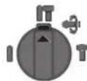
IIOJKeHHaJI npΦopauB 6eToHi a60 KaMeHi
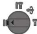
PonokenHnIeCBepnHn63yapyB
IpeBnHi, Metani, Kepami i nnaTmaci, a
TAKoK dIa3kpyuBaHHraBHTIB
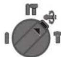
PonoJKeHHaViooLocknpeRyIIOBaHHa
noJoxeHHpOboQOrIOHCTpyMeHTa npiDob6aHHi
Bcbomy nnoXeHHI nepeMkaq peKmMy CbePdienHn/DoB6aHn 9 He fikcyTbCn.
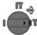
BctahOBHeHHHaHnPmkyo6epTaHHa
3a donomoroI nepeMHkau HanpMky o6eptHa 4 MoKH MaHrHanpMOK o6epTaHn IHcTpymeta. OHaK ce He MOKNBO, kUO HaTCHyTN BmHKaU 6.
06eptannpabopy:NoepnHb npemka HnpanMky oepTAn4 3 06ox 6okIBdo ynpoy B nOIOKeHH
06eptanHnIbOpyu: NObepHItnbpeMHKaHnPaMky 06eptanH43o6ox6okibdoynopyBnIoKeHH
IJIpePphiapciB6eToH,CbepDneHHiIOBbAHN3aBXn BCTAHOBNIOTnpaBnHnpanmOKo6eptaHH.
BMHKaHHBMMKahH
-
- IIO63aΦikcyBn BmNkau,TPMaHTe HOroHaTHCHyTm I DODaTKOBO HAHTCHiB Ha KHONky iKcaui 5.
- Uo6 BmKHytn eneKtpponpHnad, BiDnyctItb BmNka4 6. RaIIO BmNka4 3aafikcoBAHn, Cnoatky HaTCHITb Ha HbOrO i NotIM BiDnyctItb NOrO.
3MipkyBaHb 3aoUdXeHHN EneKtpoeHepri BmkaTe eneKtpoiHCTpyMeHTnIeToi, konu Bu 6npaTecb KopHCTyBaTcH NIM.
Hactpoobannkibkocti 6eptrib/kinkbocyt yaprib
KInbKicB o6eptI yBIMKHyTOro eNeKtPpOnpNaJy MoKaHa nnabHO perynOBaTH 6InbShm UH MeHN HAtnckaHHM H BmHKaY 6.
Pn HeCNbHOMy HATNCKyBaHHi Ha BHMnKa 6 KINbKICTb 0eptIB/KINbKICTb yapIb HEBENka. Pn 3bnBHeHH Cnnn HATNCKyBaHH KINbKICTb 0eptIB/KINbKICTb yapIb 3pOCTaE.
3ano6ixha myfTa
Pn3akHHeHHa6 cinHHi eneKtpponpaNy npHBOD CBepdNbHorO wHHDeIra BmHKAcTbCBAxauOn Ha cIN, 10BHNKaIOb PnU cBOMy, 3aBXdn Do6pe TpMaTe eneKtpponpnaIabOMa pykamn i 36epirate CTiKe nONoXeHH.


114|YkpaIhcbKa
ypa3i 3actpbaHHB BMKHItb eektpponpna i 3binhItb po6oouin IHcTpymEt. PnB BMKAHH ieKtpponpnaIy i3actparrnM po6oum IHcTpymENTOM BHNKaIOb BENk peakuiH Mometn.
Bka3iBkn 0o0p060tn
Pepd 6ydb-akmm MaHInynaizm3 enektpponpnaDOM BHTARHITb WTENCEB 3 POETK.
3mieHHH noIoxeHH pizu (Vario-Lock)
Bn MokeTe 3aipikCyBaTH p13eUb y 36 nOIOKeHHx. Lc daCTb Bam 3MOry npauOBaTH BONTMalbHOMy nOIOKeHHi Tina.
- BcTpOMiB pi3eB B nAtpoH.
I NobepHITb nepemKaupekmy CBepeHneHHaHO9 BnOIOKeHHA Vario-Lock》(INB.《BCTaHOBHeHHpeKmy po60TH》,CTOp.113).
-NoBepHtB 3aTnckau pOboQoI IHCTpyMeHa BIDNOBIDHO6baxHoNIOJKeHHp3u. - NObepHtB nepeMnKaay peKmMy cBepnneHHr/IOB6aHH 9 B NOJoxKeHHg IOB6aHH. NaPOn Tenep 3aFikCOBaHH.
-ДЯ DOB6aHHNoTpiHbI npaBn HAnpMaOK 0ePtaHH.
BCTPOMHnH6IT (DnB. Man. H)
PnctabnIte enektponpmaaddo raKu/rBHTa Hne y BmKHyToMy cTahi. Po6oui hCTpyMeHTN, 0o o6epTaHbC4, MoKyTB 3iCKOB3yBaTN.
ДябВamNotpibha yHIBePcAlbHa DepeKbKa 223 xBOCTOBiKOM SDS-plus (npnna).
- PpOuHCTiB KINHcK XBOCTOBnKa i TPOX 3MaCTiB HOrO.
- NoBepTaIOU, BCTPOMiTb yHIBEpcAnbHy DePjAkBky BnatpoH, uo6 BOHa yBiMnHa y 3aenenneHna.
IpepeipTe pikcaio, noTaryBn 3a yHibepcAHy depxabky.
Bcptpomitb 6ity ByhyihepcanHy Depkawky. BnKOpncToByte nwn 6tH, 10nacyHb do rnoBNKn TBnHTIB.
UoB BnHnTynHbepcAbnHy DepeKabky,NotHnHtB φikcyOuy BtyNkY 3Ha3aI i BnMItb yHbepcAbnHy depeKabky 223 natpOHa.
Texhiue 06cnyrobyBaHHaicepBic
Texhiehe 06cIyroBvBaHH i ouHneHH
Pepd 6ydb-KNMMAHInyuaiMa3 eEnktpponpna-dom BHTARHITb WTencBb 3 pOeTKN.
106 enektpponpnaipnau npaioBAB kicho i haidno, TPhMaTe npnaiaiBEHTnlauiHIO TBOPN BHCOTI.
Kkio Tpe6a NOMiHrN iDcHbAHL KAbH, ce Tpe6a pO6nHa fipmi Bosch a6o B cepBicH MaiCTepHIN eneKtpoHCTpymHeTib Bosch, uOb yHKHTn He63neK.
ypaizonokxgeHHHnnno3axhCHoroKOBnauKaHOro Tpe6a HeraiHo 3amIHHT. PeKOMeHNyETbCh po6HTN ce B cepBcHIM MaIcTePHI.
KoHHpa3nCIA3aKINHHeHHpoBHTnpOuHaaTe 3aTHCKaPpObOOrIOHCTpyMeHa1.
Cepbic Ta HadaHHa KOHCyIbTauii 0oO BnKOpNCaHHa npodykii
CepBicha MaicTepeHbIiNoBICTha 3aNHTAHnCTOCOBHO pemOHTy iTexHcHOro oCbNyROByBaHHBaWOro BnPo6y. MaHONKh B DeTaNIX iHOpMaJIO 0Io 3aNactNH MoXHa 3HaHTs aDpecoio:
www.bosch-pt.com
KomHaI cnBpObitnHkBosch 3 HadaHH KOhcybTauii
UoIO BnKOpNCTaHH npOdykuii i3 zaoBOJIeHHM BiJIOBICTb
Ha Baai 3aHTAHn CTocOBHO hawoi npOdykuT Ta pinnadn
do Hei.
PnBcixdoaTkoBNx3aHHTaHHxTa 3aMOBHeHHi 3aIacTHN, 6yNb nacka, 3a3Naayte 10-3NaHn Homep dna 3aMOBHeHH, 10 cToTb Ha NaCnpTHi Tablunu npOpykTy.
IapantHHe 6cnyroByBaHHI pemOHTE nekTPOIHCTpyMeHTy 3JINCHIOITbCBAINOBiHO DO BHMOR I HOPMBHROTOBIOBAaHa TepHToPi BCIX KpaIH NHE y fipMOHX abO
ABTOPH3OBAHx cepBicHNx uehtpax fipmN Po6epT BoW. IPONEPEJXEHH! BIKOPnCTaHH KOHTpaKaTHoi npOyKuII He6e3neue H E KcIpyatauMoKe MaTH HeraTNBI HacNIkN dna 3dopOB'a.BIRTOBHeHH i PO3NOBcIOJKeHH KAHTpaKaTHOI npOyKuII nepeCNIyEc7bcra 3a 3aKOHOM B aDMiHcTpaTBHOMy i KPMImHaNbHOMy nopAky.
YkpaHa
TOB «PobepT Bou»
CepBicHHIeHTpeEneKtpoiHCTpyMeHTIB
Byn.KpaHn,1,02660,KnIB-60
YkpaHa
Te.n.: (044) 490 24 07 (6araToKaHaJIbHnI)
E-Mail: pt-service.ua@bosch.com
OphiuiHn caT: www.bosch-powertools.com.ua
Apeca PeriohaBnHex rapaHTiINHX cepBicHnx MaIcTepeHb 3a3Haueha B HaioHAhBHomy rapaHTiHOMy TaHOI.
Ytniiaui
Enektpponpnai npnana i ynyakobky tpe6a 3daBaNHa ekonoriuho ncty noBtophy nepepo6ky.
He BnKuJaTe eNeKtpoHcTppyMeTHN B No6yToBe CmTTI!
Пишдя Край EC:
Bijnobinno do eBponecbooi dnpekTbN 2012/19/EU npo Bijnpaocobani eneKtpo-i eneKTPOHI npnana II nepetBPOEHNA HauioHbHOMy 3aKOHOABCTBI eneKTPoPnpani, 0u BNwn 3BXNBAAHH, NOBNHHI 3daBaTHC OKpeMo iYTHIN3yBAHTc EKOLOIHYO NCHM CNOCOBOM.
MoxnHBi3minH.
Ka3aKa7a | 115
Ka3aKwa
EHipyuiHHHIM yiwH KapactbIPfAH naDalaHy KxattapbHbKpaMbHna naDalaHy XeIHderiOCb HcayibK,cohBMHe6ipreKocbIMwanapda60nybl MyMkiH.
Caikeki pactay kaihny aknapat KocbImada 6ap.
Ohimdi eHipreH Memleket Typalbaknapat EHHIN
kopnycbHda XHe KOcblMaada KepctinreH.
OHyI HcyaybIKbH COHbI, Myka6a bTeHne KepcetirreH.
MnnpTaybI KOHTAKTIK MAniMeTIH opamada taby MyMKIN.
Ehimi nai danany Mep3imi
OhimHnKb3meteryMep3iMi7Xbl. OhdpinreHmep3imHe6baTan (ohdpy KyHi 3aybIt TaKaTaNacBHaJxkaBnFaH)ICTeNl5Xbl cakTaFahHH coH, hIMDi TeKcepyci3 (cepBntk Tekcepy) naDalaHy ycBhlMaJbI.
Kb3MeTKeHeme NaDanaHyubihhKaTeiKTEpi MeiTeH bHy ce6entepinH ti3imi
-TyKacbMeH KOpnycbl6y3bIfaH 60nca,OHIMni naDanaHa6aHb3
- eHimKopnycblHaHTiKeIeIy
-TOKcMb6y3bIFAHHEMeceokuaynaycb6bonca, naDanaH6aHb3
-kayBH -waBbH Ke3iHc bipta (ana ana) naDanaHa6h3
- Kopnyc iwihe cy kipce Kypblfblb Kocyblb60MaHb3
KeIyIKbH WbIKca,naIaIaNbSaHbI3
KaTbI dpiIN Ke3Ine naIaIaNb6aHb3
Uekri Kny bEnrinepi
-TOK CbIMbHbH,TO3ybl HeMece 3aKbIMdaHybl
-0HIM KOpnycbHbH 3aKbIMdaNybl
Kb3MeT KepeCy Ty pI MeH xiniriri
Op naIaIaNhyad coH eHIMJI ta3anay ycbHbIaNbl.
CaKray
KpyFaKxepDe caKaTay KepeK
KorapbTempepatypa KeiHeH Xane KYH Caylenepin H acepiH anbcackayKepek
- cakay KeiHne TemnepaTypaBih KeHET aybTKyblHaKopfay Kepek
-opamcb3 caKTay MYMKiH eMEc
- cakTay wapTapbI typaIb KocbIMua aknapaTany yuH MEMCT 15150 (wapT 1) kyaTaBH kapaH3
TacbImaay
-TacbImaIay Ke3Inde EhIMdi Kynatyfa XHe Ke3 KeTReH MExAHKnBk BkTn eTyre KaTaH TbHbIM CanbHaDbl
-6ocaty/kykTey Ke3iHne NaKETI KbcATbH MaUNHaIapdbi naDanaHyFa pyKcat 6epimmei.
-TacbImaIay wapTapbl tananTapbH MEMCT 15150 (5wapt) KxKaTbH OKbHb3.
Kayinci3ik HycKaynapbI
3NeKtp KypanDapbHbH Xannbl Kayinci3dk HcykaynbIKtapbl
ECKEPTY
BapnbKayinc3dk Hcckaybtkaptbin Xahe eceptnenepei oxbhb13. TexHH
Kanik Kayinciik HcyaynbTapbH XHe eckptneepdi CaKaTamay TOKtBn COFyiba, oP TKeHe/Hemece aybp JapaKaTahynapra anbl Kenyi MymkiH.
BonaawKxMblctap yuiH kayinci3dk HycKaynbkTapbi Me h eceptnenepi caKan KObbl3.
Kayincikn HycaynbkaptbHa naanahbInfah "3neKtp Kypan"ataybHbHKeiIeH Kyat anaTbH 3neKTP KypanapbHa (XeniniK Ka6eni Mehen) Xane AKKyMnyTopen KyaT aanaBtB 3neKTP KypanapbHa (XeniniK Ka6eni Jok) Katbcblap.
XyMbIcOpbHbHbKayinci3di
KymbocpHbIN Ta3a XeHe KaKcbi KApblTaNFaH XaFdaNda YCTaHbI. TepIn Hemece KapbIK 60nMaHaH Kymbc aMaKTapbl Xa3aTaBIM OKfAnapfa anbl Kenyi MYMKIH.
KHaTbH CybIKbTKap,ra3dap Hemece WaH XNbINFaH Xapblbc Kayini 6ap Kopwayda 3neKtp Kypanbl naDanaH6aHb13.3neKtp KypaIaNpaBly WkBn HbIFapBn, WAn Hemece 6ynapbl KaHdbpybl MymKIn.
3NeKtp KypanDapbH NaIaIaNay Ke3IHe 6Banap Xehe 6acka aadamapdby y3ak Xepre weTteri3.
TITAYHKAKAKKAKKAKKAKKAKKAKKAKKAKKAKKAKKAKKAKKAKKAKKAKKAKKAK
3nektkayinci3iri
3neKtp Kypan wTencenHin aBbipbpo3eTKaFa cbIOki KaKet. AibipdbEwKaHdAn 03repty MymKIn Emec. Kepre kocynbl 3neKtp KypanDapMehen ewKaHdAn adantepnik aBbipdbn naDanaH6aHb3. 03reptimereH aBbip jHe JapaMdb po3eTkalapDb nAdaNaHy 3neKtp TOK COY KAYINIH TEmeHTeI.
Ky6bip, XbInbTaBn Xa6Dbk, NnTAtXHe cyBtBn ChAeTbXepre Kocynb KypanapcbiptbHa TMHei3. ErepeneHj3 Xepre Kocynb 6oNca, 3neKtp TofBtBn Cofy Kayni apTabI.
3NeKtp KypanapbH bInFaH, cbIaH caKaTaHbI3. 3NeKtp KypanbHbH iWHe cy Kipce, on 3NeKtp TOBbHbH cOy KayPiH apTbIpaBbl.
3nekp Kypanbl anbnx npy, acbn KO He mece aibpbiH po3ekadn wbrapy ywn Ka6ebdi naDanaH6aB13. Ka6ebdi bCTbIKTah, maDAn, 0TKip WeTTepHe Hemece KypanblH XblXbIMa 6eKtepiH anbc xepde ycTaHbI. 3aKbIMdaHaH Hemece WneHicKeH Kaben 3eKtp TOfbHbIH COY KayniH apTbipabbl.
3NeKtp KypaBImeH awbIK Xepde Kymbic ictecenhi, TEK CbiptTn naDanaHyfa apHanFAH y3apTKbltBi naDanaHbHbI3. CbiptTn naDanaHyfa apHanFAH y3apTKbltBi naDanaHy 3neKtp ToFbHbH COy KayniH TEmeHdTei.
3NeKtp KypanbH bInfanDbI KOpWayda naJanaHy KaKet6oNca,ABTomATbI cKaTaNbIPbIaXbIpaTkblshn NaJanaHbHbI3.ABtOMaTbI caKaTaNbIPbIaXkbIpaTkblTbNaJanaHcyTOKcoFyKayniH TMeHJeTeJI.
Aaamap kayinci3diri
CaK60bn,HeICTENXaTKaHbHb3FaaipbikkaKeHIN 6enin,3neKtp KypanbH petimn naDanaHbHb3. Wapwarah XaFdaHa Hemece enitKiu,AnkoronB


116|Ka3akwa
Hemece aepi acepi actbHa3neKtp Kypanbln naDanaH6aB13.3neKtp Kypanbln naDanaHyda cekyntbik abacbI3dbk KaTbI kapaKaTTaHynapFa anbIn Kenyi MymkiH.
Xeke caKtaIbH KImdi Xehe epaIbIM KOpFaHbI W Ke3inipikti KIni3. 3neKtp Kypan Typine HEmec e naJaIaNHyBaHa6aIIaNbHcTbI WaHTyKbIb, CbIPyDah CaKaTaIbIH 6TeHKe, CaKaTaIbIH Wnem HEmec Kynak CaKaTaBbIb ChRkTbI Xeke KOpFaHbIC Ka6DbIbKTapbIH KHO JapaKaTAtHy KayPiH TEmHeDeTei.
BaiKaycb13 naDanaHyaHaayak60nbHb3.3NeKtp KypaBnIH TOKxaXHe/Hemecae AkkymyTOpraKocya, OHbl KeTePreHne HEmecae anbIn KxpyHne, eWipyni 6onybHaKe3 KeTki3H3.3NeKtp KypaBnIH KeTeepin TyFaHa, GabMaKtbl AkaBpaTkBuTa YcTay HEmece KypbIbHbIKocybl KyJde TOKKa KOCy, Xa3aTaBIM OKFaFNaFa aBnI Kenyi MYMkH.
3NeKtp KpyanbH KocyaH andbH peTteTIN acnantapblxhe raKa kInTepiAnbictaTbHb13. AHHanaTbH 6eKeTe TpyFaH cnaH Hemece KINT JapaKaTaHaNpRa aBn KenyIMKIN.
Kanbcb3 De He KyinHe TpyMaHb3. Tipek KyuT pybIn, epKaawan e3ihi3i ceHimdi ycTaHb3. Ocbna i3kyTnerEH KaFda 3neKtp KypanDb JkaKcbpaK 6aKaIaNcB3.
Xymbicka kapaamblkim Khihi3.Keh hemece cahni kIM KMIeH3. Wauhbi3db, KIM XaHE KOJFaNTb Ko3fAmnb6enweKTepeH anbc yctah3.KeH KIM, oWekeH HeMece y3bH wau K03fAmnb6enweKTepre THOI MymkiH.
WahcnpfbwXeHaHTkBwXa6dbkTapdbkyphaHda,OnapbH KocbHFaHbFbHaXeDpybcnaIaNbHyBaK3XeTKi3i3. WahcnpfbTbnaiIaNanHywac6e6iHe6oIbHKayinTpdi aasraDb
7 Tyka (6eti OkwaiyanaHdbipbIFaH)
8 KaFyDbl/aHnanyDbl ToKtaty KockblbHbH6OcAty TymMeueci
9 KaYdyb/aHaHaNyDbTOKTaTy KCKbIbI
10 Tepehdiikti wektey tiperih opnaty nepheci
11 Tepehdiik wekteriwi
12 KocbIMwa TyTKa (6eTI OKwauHaNdbipbIFAH)
13 Təkkik 6yfbinay natpohbl ywiH ToKtTkbl 6yfb
14 Ticti Taekik 6yfbnay naTpoHb
15 Bypfnay naTpoHb yuii SDS-plus-acn an npohb
16 Saugfix copy caHbI nahyi*
17 Saugfix KbicaTbH bypamacbi
18 Saugfix Tepehikti Wekey Tiperi
19 Saugfix Teneckontbik Kybip
20 Saugfix kanaKtbI bypfblcIb
21 Saugfix 6aftbTTaybiKy6bpBt
22 SDS-plus-acn anatpOndbik am6bean yctabii
*EeHeneHHe HEmec He CNnATAnFAn Jx6b4kTap CTaHApTbI Kek3iY KeenMeHem KaMTbInMaBdI. TOnbKx6b4kTapDb6i3iH Xa6b4kTap 6aBdpamAmMaBdHaTabAcB3.
UybinKHeDipinDeyypaIbIaknapaT
Uy3MnCCnBcHbHmHHePi EN60745-2-66oHbHaa ecentenreH.
A-Men 6nirineHre HneKtp KpyanbH ubyin DeHre i aTeT TAmeherire TeH: bIb6bc Kyui 91 n5(A); bIb6bc KyaTb1 102 n5(A). Oneuey danci3iri K=3 n5.
Kynaktbi Kopfay KypandapbH KniH3!
KbHtBkDipin MAni a (yW 6afttbH Bektopblk KocbHbc) XeHe Kdnci3iri EN 60745-2-6 cTahdpTaHa caaahbIKtaFaH:
BetoHbI npΦopatopMeH 6ypfbnay:ah=17,5M/c², K=1,5M/c²,
O10: ap = 14M / c2,K = 1,5M / c2 MeTanblb6yPbIbay:a<2,5M/c²,K=1,5M/c²
BpyHaIaIap:a<2,5M/c,K=1,5M/c².
Ocbeceptnepe6epinreHipiney npmehi EN 60745
epexecinde moniupnehenr enuwey aici 6oynihwa
ecenlenren 60bn 3nKTP Kypanapdib 6ip-6ipimeh
canbctby ywih naaanaahnybmyMkH. Onipindey kyabh
waaman an newey wih de jkapambl.
Bepireh dipin Kelemi 3neKtp KpaIbHn Heriz
KymbcTapbl yuH bepireh. Erep 3neKtp KpaIb6aKa
KymbcTap yuH tyPi kepek-kapaTapmeh 6aca anMaIbI-
caImaIbI acnTAP Mehen Hemece Xetimci KyTuMeH
naIdaIaNbIc aDipinJey Kelemdepi e3repeDi. ByI Kymbc
6apbcHdAfpil kaytbH apTbPaIbI.
Dipiney KyaTbH hakTeY yuiH kpaI eWipinreH xane KocBfAH BOnbIn naJdanaHbIMaFah YakBITapDbJa eCKepy KaKet. By dipiney KyaTbH 6ykin XyMbic yaKbITHaKaTTb ToMeHDeTei.
NananaHuybHb dipindey aceiphen caKayTAYuH KocBmua Kayinc3ik wapanapabH kondaHy kaxet,MbcaIb: 3neKtp Kypanblx He anMaIb-camMaIb acnTAPdb KyTy, Konnapdb bCtbk yCTay, xMbc dicTepiH ymbmdbctbpy.
TexHnKaIbIK MJIImeITep
| Перфоратов GBH 2400 | ||
| ФИМ НЕМИР | 0611 2538.. | |
| АйнавIMдар санын баckару | ● | |
| Айналды тokтату | ● | |
| Онга/солfa aihaу | ● | |
| Кесимд Качып падалану | ВТ 720 | |
| Кагулар саны | MHN-1 | 0-4000 |
| Бір кâгу куаты 05/2009 EPTA працудypасы boиьша J | 2 | . |
| АйнавIMдар саны | MHN-1 | 0-900 |
| Асан пантоно | SDS-plus | |
| Шпндөль моны даметрì | MM 50 | |
| Мakсималды bурсылay даметрì: - Бетон | MM | 24 |
| - Курсылс (шенирлик бурсылay коронкасы) | MM | 68 |
| - 6 ол aт | MM | 13 |
| - a раш | MM | 30 |
| EPTA-Procedure 01:2014 Кужатына сан салмамы | KF 2,7 | |
| Сачык сынblы | ☐ /II | |
| Молimerтэр [U] 230 В kecisdimі керseyre aphanfah. Басka kerseyждан eile Keabiiцанган задар bул молimerтэрді заэгету муMKIN. | ||
118|Ka3aKa7a
XnHay
BapnbK JyMbIcTapdAnbH 3eKtp KypanbHbH Jxeninik aibpbH po3eKaad HbIFapbHb3.
Kcbimua Tytka
3nektp KypaBbHb3dbTekKocbIMwa Tytka 12 Mehen naDanaHbHb3.
KocbImuayTKaHbI aybIKbity (A cypetin KapaHb3)
KocbIMuTaTKaHb12 KcCatbIn 6eKem XeHe WapUaTnBtH Kymbc KyinOpHaTbH3.
KocbIMua TyTKaHbH 12 TeMeH 6eneriH caFt Tinihe KapcbI 6ypan, KocbIMua TyTKaHbH 12 KepeKti KYre 6ypaHb3. CoCbIH KocbIMua TyTKaHbH 12 TeMeH 6enirH caFt Tiniem H 6ekiriN 6ypaHb3.
KocbMua TuKaHbOpayTacnacb KopynciHderapHaBb ObikTaXaTybHaKe3XeTki3H3.
Bypfnbain Tepehdirn opnaty (B cypetin Kapaiba)
TepehdiKTI WeKTeY TiperimEn 11 KaKeTTi 6yPbInay TepehdiIRH X peTey MYMkiH.
-Tepehiktiwektey tiperih opahty 10 nephecih 6acbln Tepehiktiwektey tiperih kocbimwa tyTKara 12 opHaTbHb3. Tepehiktiwektey tiperih 116ydbipnyi TEmHeK Kepcetyi KaXeT.
- SDS-plus-anmabI-cammabI acnabH SDS-plus 1 acna6bl natpohHa tipeReHwe XbIbTbHb3. Kepi KaIaJaSDS-plus-acna6bHbH XbIbMAbIbIbFb6yPbIay TepeHirine Keate opHaTbIybi MYMKH.
Tepehikti WekeTey Tiperih 6yPbI yUbIme TepeHikTI WekeTey Tiperi YuBHH apaBIFkKaKETTI 6yPbNay TepeHirHe X TEH 60FaHbIHwa TaPTbHb3.
Bypfbinyatpohmbmehacnantapdbt Taay
Nepfopatopmen 6yfbnay xhe oio yuih SDS-plus acnan naTPOHbHa cIbHaTbIH SDS-plus acnantapb kepek 6oana. KaYcbl3 aafTb, metanbl, KepaMHKaHbI, nlaactMaCCahb Ixhe 6ypaHdAnapbl 6yFpHanay uWih SDS-plus cb3 acnantap (MbcaI bUHHDPIK TtKanblk 6yfbnap) naDaHaBnabI. Ocbacnantap yuH XbIaam Kbcy 6yfbnay naTPObI Hemece tict TaXik 6yfbnai NaTPObI KaKet.
Ticti Toxik6yprfbnay natohbin anImactbipy
SDS-plus-c3 acnantapbimeh (MbcabnuINHHp TTKanbIK 6yfbj) xmybc ictey ywihc aikec acn an natpohbiH opHaBHbI3 (Ticti TAnkHemece Kblamd Bekity bypbnay naTPOhbl,KepeK-kaBkTap).
Ticti taekix 6yfbnay natpohbiH ophaty (C cypetih kapaht3
-SDS-plus-acn natpohIn 15 ticT tckik 6yfbinay natpohIna 14 bypan 6ekitih3. Tict Tckik 6yfbinay natpohIn 14 toktaKbIb 6paHacbImen 6keiH3 13. ToktaKbIb 6yfbcHbHa con 6afbltbk oHa 6oataBbHa H3ap aydpabHb3.
Ticti Toxik 6yfbinay natpohbuH opHaty (C cypetih kapaHb3)
-TyTKaHbIH CaJIbHaTbIHybIH Ta3JAN, a3JaMauNaHbI3.
Ticti Taekjik 6yprbnay natohon acnan natohha e3i 6ekirirene 6ypan calhbl3.
Ticti Taikik bypfnay natpohbiin 6ekitinyin tapbnt Ekeepih3.
Ticti Toxik 6yprbinay natoPohbH wblfapy
BekityTeKecin3apKaXbIbXbITbINTictiTaXdiK6ypfbnay natpoHb114weuhi3.
Kymbic Kypanbih aybictbipy
UaHnAH CaKaTaNbH 6yKbTpMaMeH 2XyMbIc IcTeY Ke3iHe6yPbIaay HaBbHbIH acnAn natPOhHa KpyiHe Kon6epMeJI. AcnAHTbN aNdAnaHydAn anDbH WaHHaCaKaTaNbH 6yKbTpMaHbH 2aKbIMdaImFaHbHa Ke3KeTki3iH3.
3aKbIMdAnfah WAnHah CaKaTbH 6yKtbpMa 6ipDe H anMaCTbIPbJybl KaXeT. Ohbl Kbl3MeT KepeTy We6epxAhcBHaOpBnHday YcbHbInaBl.
SDS-plus 3nektp KypanbH naiDanaHy (DCypetIH kapaHbI3)
SDS-plus-bpfnay natoPbHMeH anMaIb-cnMaIb acnantBkai kHe OHa peTc KocbIMua acnTapdb naDanaH6aanMactbpy MmKIN.
-AImaIbI-cmaJIbIacnIbIHCanbiHaTbIHyBHTa3aIaI, a3dIaMnaIaHbI3.
-AnmaIb-camMaIbJxMlbcKypaIbHnATPOHfaabTOMaTTb6ekitirreHwe 6ypan calIb3.
-Kypandbin6ekitinyiH tapTbIn TeKcepiH3.
SDS-plus-anmablcmanlaacnabkyue caandapbnaH 6oc k03fana,b. Con cebenten boc aHHanyda paanl kary naJa 6onably. By onbIK dypbictbfbHa acep etnei, eHTkehi 6byfnay Ke3inhe 6byfpei optara dAn KENTipei.
SDS-plus anmanbi-canmanbi acna6bH wbfapy (E cypetin kapaht)
-BeKity TENKecih 3 apTKaXbIbXbITbI anMaJIb-CaMaJIb acnantbl ueiHj3.
SDS-plus-c3 anMaNbI-canMaNbI acnTapDbI opHaty
Eckptne:SDS-plus-ciacnantapdbnipfopatopnbk 6yfbnay hemece oio yin naiandaanb6aib3!SDS-plus-ci3 acnantap npfopatopnbk 6yfbnayda hemece oio da 6y3bnab.
Ticti Tckik 6yfbnay natoHb14 ("Ticti Tckik 6yfbnay natoHb1 anMactby", 118 6etihde kapaHb3) opHaTbHb3.
Ticti Taekik 6ypfnay natoHb14 acnan opHaTbIaHbIa 6paHb3. AcnantbOpHaTbHbIa.
-6yfbnay naTPOhBI KInTH TICTaKIK 6yfbnay naTPOhBiHbH 14 Tiicti OBykTapbHa opHaTbN acnantbI 6ekitH3.
KaFybl/aHanybl TOKtay KockblbH 9 "6ypfbIay" KyiHe aHnblpblb3.
Ka3aKa7a119
SDS-plus-ci3 anMaIbI-canMaIbI acnTapDbI weu
Ticti Tckik 6yfbnay natpohbiH 14 6yfbnay natpohkiinimercaraf tinihekapcb6afttaanmanbi-cammanbI acnan weuirehewe ypaht3.
Saugfix Mehen uahcopy (kepek-kaapakTap)
KopacbH6oY,Keibip aaw copTapbl, MInhepaanap XHe MeaInap 6ap Keibip MaepnAapabH uha DeHCaynbKa 3HHbI bOybl MyMkn. WaHa TIO XHe XaDb Jkyu naDAnAHyBda HEmec XaHbNAdFb IaMnpa anPepnBbIK peaknnapbl XHe/Hemce TbHbc XOJdpabH aypynapbl Tydbpyb MyMkiH Keibip wH tynpel, acipece eme XeH MaWat aafbHbHwHbI, acipece, aafTb EhDey KaNbltapbMe (XpOMaT, aafTb Kofay 3aTb) bipre KaHeporeHep 60bn encTepei. Acectik MaepnA TeK KaHa MaMaHapMeH eHDenyi KepeK.
-MymkininirihueocbmatepnaiyihcnkekeneiH 1haHc0pfbIbI naaHaHbHbI3.
-¥MbicOpbHbHbHJxKcbJxKeIeTinyiHe Ke3 KeTk3iHi3.
-P2 cy3ri cbiHbInbHdaFbIra3KaFapDbl naHaanHy cyhbnabbl.
HneTIN MATEPnAnIap yuiH eniH3ne KOnDaHbNaTbH yIaFapBIMapDn naDnAHaHbHb3.
KymbocopbihdaaHbIHxHanyib6oIbipMaHb3. 1aHohayyMmKIN
Saugfix ophaty (F cypetin kapaib3)
UHaCOpy ywH Saugfix (KepeK-ka6bIk) KaKet 60aIbI. ByPbIay Ke3Ine Saugfix apTka cepninei, con ywH Saugfix 6acbl ApaIbIM Ty61He 60aIbI.
-TepeHikTIweKteYtiperIHOpHATy10nepHecIN6acbin TepeHikTIweKteYtiperIH11WeuH3.10nepHecINKaTb 6acbin SaugfixKocBIMaTyTKaFa12anBuHaOpHaTbHb3.
- Copy shaHbH (nAmetpi 19 MM, KepeK-Jabik) Saugfix copy caHbIaybHa 16 KocbHb3.
山hcofpbiu eHdeneTIn MaTePnAnFa caikec 6nybl KaKeT.
DeHCaynbKKa 3nH,06bIpyfbl3aTbH HEme Kpyprk.uaHap yih aphaBlaWahcOpfbTb naDanaHbHb3.
Bpyfnay Tepehdirn Saugfix-Te pettey (G cypetin Kapaht)
KaKETI 6yPbInay TepeHirIH X OphatbInFaH Saugfix perihde De opHaty MymKiH.
-
SDS-plus-anmaIb-camMaIb acna6bIH SDS-plus 1 acna6bl natapoBHa tipeReHwe XblXkbITbHb3. Kepi KaFaJaSDS-plus-acna6bHbH XblXkbIMaJIbIbFb 6yPbIay TepeHirine Kate opHaTbIybi MYMkih.
-Saugfix copy KypblfcbihdaftkaJAAKTb6ypfblhbl 20 6ypan 6ocatblHb3.
-3neKtp KypaIbI Kocnactah Kymbc 6etHe TypaKtIeIn opHaTbHb3. SDS-plus canbHbAnbI KypaIbI 6yn Ke3e6eTE opHaTbINFaH 6onybKepeK.
Saugfix 6abfttaybi KybipbH 21 KpOHHTeHne Saugfix 6acbl 6ypfbaHaTbH 6enikte 6oNaTbHdAn KblNkBtBbIb3. TeNEcONtbK KybipdaFb 19 WkaNaHbH KeN 6eniri KepiHyi yuH 6abfttaybi KybipDb21 TeneckOttbK Kybippa 19 OaH aPj KblKbTnAbH3. -
KaakbIb6pyfblHb206epik6ekmEni3. SaugfixTepeHnIK WkteriWiHderi KbcatbH 6ypamaHb176ypanabHb3.
TepehdiKtweKtey TiperIH 18 TeleckontbIK Ky6bpda 19, cypTe KepcetinreH KaBbKbTKX KaKet 6pyfblay TepehdirHe CaiKec 60aTaHdA KxblkBbTbHb3.
-KbicaTbH 6ypamaHb176epik6ekmdeH3.
PaiandaHny
Taindanahya eHdpy
Xeni KyatbHa Ha3ap aydapbHb3! ToK Ke3iHIn KyatbI 3NeKTP KypaIbH 3ayblTbIK TaKTAWacbIHdFaBf ManimETepine ca86nybl KaXeR.230 B6Enricimen 6enrinereh 3NeKTP KypaIbApbl 220 Bxymbc icteyi MYMKIN.
Painanany typin opnaty
KaFydb/aHAnydbTOKTaTY KCKbIbIMe93neKTP KypaBbHn naDanaHy TypiH TaHaHbI3.
Eckeptne: Paindany Tyin TK 3neKtp Kypanbih 8wiipin 03reptihi3! 9ntnce 3neKtp Kypanbih 3aKbIMday MymkH.
- PAnDAnany TpyiN 03repy TuWih 6ocaty TyMeueciH 8 6acbin, KaFydi/aiHaNydi ToKtaty KockbluH 9 KepeKTi KYHe DblbcnH TipeIReHwe 6ypaHb3.
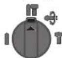
BetoH Hemece TaTbI nepfopatopnbIK 6yfbnay Kyi
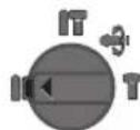
Araa, Metan, Kepamika KeHe
nactMaCCaHb KaFycB3 6yprbnayKeHe
6paHaKaIO Kyi
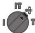
Vario-Lock Kny Kecku KyH eaepy Tu H Byn Kynde KaFydb/aHaNaydb ToKTaty Kockblb 9 tipenMei.
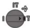
KyHH Oiora
AHHany 6aftbIbH opHaTy
AHHany 6abftbHbH aybctbipn-KCKblbHbH 4 Kemerim H aHHany 6abftbH enweyre 60ana. Bipak KCKblTb/ewipriu 6 BacKaHa 6 by MmKIn eMec.
Onfa aHany: aHany 6aFbITbIHbA aybICTbipIN-KOCKblB1H 4 eki xkaKa opHbHaTipeIreHwe bpaH3
Conra anHany:AnHany 6aftbHbH aybictbpinKocBbHbH 4 eki xakka opHbHa TipeIreHwe bpaHb3
Nepopopatopnb6yfbnay,6yfbnayxhe0iyinaiHany 6aftbTHApdaBIM OHFa peTHei3.


120|Ka3akwa
Kocy/ewipy
-3neKtp KypanbIH Kocy ywIH Kockbi/ewipriwi6acbHb3 6.
-Kockbiu/ewipriui6yfarayuyuHOBi6acbinyctan petteyTuymecicin5Kocbmu6acbHb3.
-3neKtp KypanbH eipy yiwH Kockbiw/ewipriwi Xi6epiH3 6. Kockbiw/ewipriW 6 tipenreH coH, eyeni OHb 6acbin cobin xi6epiH3.
3Heprn KyatbH YEmdey yIiH 3JIeKTP KypanbH TeK naIanaHaHapDa KocbHbI3.
AHHaHbIMdap/kArfCaNbIHpeTey
Kocbltbl/ouipriu6bacykyuih e3repeotbipin, KocfaHAnEneKtp KypaBnHbH aHaBIMap/Kafynap caHbH 6iptiHepetreye60ana.
KocbIu/ewipriuke 6xai bacy tmeH aHaIbIMap/Kafynap caHbIH KocabI. Bacy Kyuece aHaIbIMap/Kafynap caHbI K6ebeiEi.
Kopraybiw XanFactbipfbiw
AnmblcnnanbI acnKbcInca Hemece inHc 6ypbnay uHHdine 6epnic ToKtaBnabl. Ocbna naiDa 6oNaTbH KyuTep ce6e6iH eNkTp KypabIn eki Konmeh KaTbI yCTan 6ekem KaNbIna TpybInb3.
Erep3neKtp Kypanbl tipenin Kanca, 3neKtp Kypanbln 0ipin anmanbl-cannanbl acnantbl 6ocatbhl3. Byfattanfan 6ypfbinaTbnH acnantbl Kocy KeiHKeJXorapbl peakntBti Kyu naJa 6onaBl.
Paindany Hycaynapbi
BapnbKxMbycTcapaH andbH 3eKtp KypanbHbH jeninik aibpbiH po3eTKaHaH bIfapbHb3.
Keckiw KannbH e3repy (Vario-Lock)
Kecki36 Kynde 6ekityre 6onabI. Ocbnaon onTnMaIbI Kymbc icTey KynHe KeTe anacB3.
- Keckiwi acnan natoPbHa oPhaTbHb3.
KaFydb/aHAnydbTOKaTy KCKbUbH9"Vario-Lock KyiHe bypaHb3("PaindaIaNHy typInOpHaTy",1196eHHKe KaapHb3).
-AImaIb-CanMaIb acnantbKepeKtiO KyHHe 6paHb3.
KaFybl/aHanybl TOKtary Kockblshn9"OIO"KyHIne 6ypaHb3.Ocbnaacnan natpoHb6ekitinei.
-OyuiH aHany6aftbIH OHf aHanyfApHaTbHb3.
BypaHa yuTbIKTapbIH opHaty (HCypTeiKapaHb3)
3neKtp KpyanbH combH/6ypaHdaFa TeK owipinren Kynde canbH3. AHaNaTbH aMaNbI-cMaNbI acnTap TyciN KeTyI MyMKIH.
BypaHya yuTbKapbH naiDanaHy yWIn AM6e6an yCTaFbH 22 SDS-plus-acnan natpohBMen (kepek-ka6bKap) kepek 60ana.
TytKaHbH,CanBaHaTbH yuBbTa3aNa, a3aJaMaHaNbI3.
-AHannanbAm6eBAn yCTaBHTbkypandb6ekity opbHa aBTOMATTby Tpyde 6ekitireHHe caBbIb3.
-3M6eBanyCtAbyIITbTapTbN,6eKtiinyDiTeKcepiH3.
- YCTaftbIwka WypynTapdb6ypan 6ekrty 6ntacbH canblb3. Tek wypn 6acbHa KapaTbH KOHbIpMa 6ntanapdb naDanaHbHb3.
-Em6ebn yctafbiWbany yuHn 6ekity TeKeciH 3 apTKa XblNkblHb3 XHe m6eBn yCTafbiWb22 Kypandb6ekity opHbHaH WbIfapblb3.
TexHnKaIbIK KyTIm KxHe Kbl3MeT
KbI3MeT KepcTey KHe Ta3anay
BapnbK JymbicTapdAn anbH 3neKtp KypabibH Hxeninik aibipbH po3eKaadn bifapbHb3.
DypbcXaHe cHimdiictey yuH 3neKtp Kypanmen XeNepTeKiTu TecikrTa3a YCTaHbI3.
Erep BaIaNbHc CbIMbI anMaCTbpy KaKet 6oNca, Kayinc3iIKTH TEmeHdeYiHe KOn I BepMec yuH anMaCTbpyDbI TeK Bosch Hemece Bosch 3neKtp KpaJapabHbIH ABTopn3aunHaHfAn KInHeHTpe Kbl3Met Kepcety optaJIbKTapBHdaOpbHdAIS.
3aKbIMdaIaanFaH WAnHah CaKaTbH 6yKtbpMa 6ipDe H anMaCTbIPbJybl KaXeT. OHb Kbl3MeT KepCey We6epxAhcBHaOpBnHday YcbHbNAdbl.
-Kypandb6ekityopHb1epnainanahnyanKein Ta3anaHb3.
Tytbinybifa KbI3MeT Kepcety XeHe naJdanaHy Kehectepi
KbImET KepcTeY ue6epxHaCbI eHIMDi KeHNey XeHe KYTy, coHdAa-k KocAnBb 6enweKTeP typanbl cypaTapFa kayan bepei. KaKetti Cb36anap MeN KocAnBb 6enweKTeP typanbl aknapaTbMbHa MeKeHkaJaHa Tabacbi:
www.bosch-pt.com
KeHec6epyui Bosch Kb3MeTkePneIeHIMdi naHaanayxane onapdbn Kocankb6eIeKTepi Typalb cypaKTapbHb3ra TnaHaKtbl kayan bepei.
CypakapkoKHeKocankb6eWueKtepeTancbipbc6epy Ke3iHMeMHTeTI TpyeEHIMDlH 3ayblTBk TaKaTauCbHnDaFb10-caHbEhIM HEMPiH Jka3bHbI3.
EHnpyui taanTapbMeH HOpMaIapbHbHcakTanybIme 3neKtpyaBHHKeHdye KHe KeinDi Kbi3MeT KepCey 6apbIK MemkeTep ayMaBHaTeK "PObpt Boi" fipMaibHK Hemece ABToPi3aunHaHfAe Kbi3MeT KepCey optaBkTapbHaOpbHaJaB.
ECKEPTY!3aHb3KoJlmEn 0ekinIReH eHIMdepdi naDanahy kayinti, deHcayIbIbIbIb3Fa 3nH KenTipy i MymKiH. 0HImdepdi 3aHcb3Xacay XaHE Tapaty Akimuiik XaHe KblmbICTbk Taptin 6oBbHwa 3aHMeN KydanaHaBbl.
Ka3aKCTAH
KJIC "PobepBow
3NeKtp KypaIapdabHa KbI3MeT KepeTy optaIbIbI AnMaTbI Kanacbl
Ka3aKCTAH
050050
PaibIm6ek daHfbblb
KOMMyHaIbHaN KeWecinH 6ypblbl,169/1
Ten.: +7 (727) 232 37 07
ΦaKc: +7 (727) 2330787
E-Mail: info.powertools.ka@bosch.com
PecmncaTb:www.bosch.kz;www.bosch-pt.kz

România | 121
Kedere kapaty
3neKtp Kpaanap, Ka6dbkTap Xe 6yMaIapbH aHanaHbKopFaiTBH Kdere Kapatyfa anapyKaKeT.
3neKtp Kpynpaapdbiy KoKbIcBaHaTactaMaHbI
Tek KaHa EO eNdepi ywiH:
3neKtpxhe 3neKtpoHbik ecki Kypanapdap
60hBnHa Eypona 2012/19/EU epexecici
xHe OHbI yTTbIK 3aHapda opHdanybl
60hBnHa baca naadanaHbIN 60MaTbIH
3neKtp Kypanapd6eNeKHHaBln KaDere
kapaTbNyblKaKet.
TexnKanbIe3repctepHriy KyKbIbIcakTanaIbI.
Româna
Be3o1aceH haunHa pa60Ta
BbTe KOHcHTpPAnH, CnTe TE BHNMaTeH NoIeCTBnTa CN NocTBaIte NpeNa3NBO H pa3ymHO. HeH3NON3BaTE enEKTPOHHCTpMEnTA, KORATO CTy MOpEH Hnn NOBnHHe To HA KapKOTuH BeueCTBa, anKOxON HnYnoBaunneKapCTBa. EINH MmP a3ceHooT npn pabota c eNEKTOHnCTpyMeH ToMe J da Hma 3a nOcNeCTBHe NkKNIOHTeH IO TeKKn HapaHBAHn.
Pa6oTe c npEpa3BaOpo 6oNIO bHnHa npePnaH ouHa. HocHeTo Ha noXoJUa 3a no3BaHn EeKTPoHnCTpyMeHT n3BbpWbHaTa DeHoCT nHn HpePna3n CpeCTBa, KaTO dXxaTeHa MacKa, 3dpaBN NtHO3aTbOpEH OBykN CbC CTabHnE rpaHep, 3aunHa KcKa mH yMo3aIyWnten (aHTnFOH), HaMaJIba PnCKA OT Bb3NHKBAHe Ha TpyDOba 3NoIOnyka.
H36raBaTe onaChocTt oB KKnOuBaHe Ha eneKtpOnHCTpyMeHTa NO HeBHMHaHE. PpeH DA BKnIOUHTe ueCenLa B 3axpaHbAuaT a MPexa Hn da Noctabnte AkyMyNatopHata 6atePna, ce yBepRaBte, ye NcKOBnATneBcBAe bNOxKeHne "NkIoUeHO". Ako, Korato HO-CHTe eneKtpOnHCTpyMeHTa, DpbXHe NpCbTa cN BbpXy NcKOBnI PpeKcbAay, nko AOndaBe 3axpaHbAio HanpeXeHHe HA eNEKtpOnHCTpyMeHTa, KOrato E BKnIOUeH, CbueCTByBa ONaCHOCT O B3HNKBaHe HA TpyOba 3NoONyKa.
PnDn Da BKnIOuHTe eNeKtPOUNHCTpyMeHa, ce yBepaBaiTe, ye CTE OTCpAHNn OT Hero BCNUKN NMOUHN HTHcPyMeHTn raeuHN KIOUObE. IOMOeH INHCTpyMeHT, 3abpaBeH Na Bbptrao Ce 3BeHo, MoKe da npuHH TpaBMM.
H36raBnTe HeeCTeBHHe TNOXeHHa TnTo. Pa6oTe B CTA6nHNo NOnOxEHHe Ha TnTo H BB BceKN MOMENT NOBpKaHTe paBHObecHe. TaKaIe MoKeTe Da KOHTPOINHpATE eNEKTOPHCTpyMeHTA No-IOpe H NO-6eONaCHO, AKO Bb3NHKe HEoayKaBaHa CNTyaUHA.


128|Блгарский
Pa6oTe c nOxOaHIO 6nEKn. He pa6oTe c HnpoKn dpexn nn ykpaewHn. DpbXte Kocata cn,dpexnte H pbKaBnHa ha 6e30nacHO pa3cTOnHne OT BbPTaun Ce 3BeHa Ha eNekTPoHNCTPymEnTHe. HpioknTe dpexn, ykpaewHnra, DblITHe KOCHMOrat da 6bDat 3axBaHaTHn YBLeueHH ON BbPTaUNCe 3BeHa.
Ako e Bb3MOXHO H3NON3BaHETo HA BbHnHa acnHpauNoHHa cnCTema,ce yBepBaHTe,ye TRe E BKnOueHa H cyHKUOHnpaH3npaHO.H3NON3BaHoTa Ha acnPa-choHHa cnCTema HaamJraBa pCKOBete,dbJxauN Ce Ha OTdienuata ce npn pa6ota npax.
PnKJINBO OTHOWeHne KbM eNeKTpOHcTpymeHTHe
He npetobapbaTe eneKtpOHCTpymeHa.3noI3BaTe eneKTPoHCTpyMeHTte cmo Cb6pa3HO THXHOTnpedHa3NaueHHe. Iepa6OHTe no-dObe n no-6e3onacHO, KOrato H3NoI3BaTe NOxOJaUN eNEKtpOHCTpyMeHTB 3aIaeHnO T npOn3BOHNTe JnnaA3OH Ha HATOBapBaHe.
He hanaBae enektpoHcTpymEn, HHTO nycOB PnekebcBaue nopehen. EektpoHcTpymEn, KOto He MOKeJa 6bJe N3KIOUBAH IN BKNIOUBAH NO ppeBnDEHnEOT npOn3BOJNTeHaN eONaceHN TpRbBaJa 6bJe peMOH- TpuAa.
PpeHn da npomeHte HAcTPOHKHe Ha eNEKtpOHNCTpyMeHTa,da 3aMeHrte pa6OTHN HHCTpyMeHTn HOnbHH TENHH Pnncnoc6BHeH, KaKTo H Korato npoDbJXHTENHO BPeMe HMa Da N3No13BaTe eNEKtpOHNCHPTyMeHTa, H3KnOuBaTe uencena ot 3axpaHbAuaTaMpeKa H/Hn H3BxaJaThe AkyMaTApOpHa 6aTePN. Ta3H Mpa NpemaxBa OnaCHOCTTa OT 3aJeIcTBaHe Ha eNEKTPOHNCTpyMeHTa IIO HeBHHMAnHe.
CbXpaHbAaTe eNEKtpOHcTpymEntHe Ma MeCTa, KbDeTo He Morat Da 6bDat OocTHnath O Deca. He DonyckaTe Te Da 6bDat N3NO3BAHN OT NHa, KOHTo He ca 3aNo3aTHc HauHHa Ha pa6ota C TEx H He ca npOeynte3n HHCTpykUnn. Korato ca BpbueTe Ha HeONTHN NotpeBtEn, eNEKtpOHcTpymEntMeTOrat Da 6bDat N3KNHOHTenHO onaCHN.
PpOBepaBte daNN NOBnHHTe 3BeHa yHKUNOHpAT be3yKOpHO, daNN He 3akHNHBat, daNN HMa CuyneHH Nn NOpeHHe DetaiN, KOtO HApUbaBat Hn HMeHr ATyHKUnHe Ha eKTPoHNCTpyMeHTA. PpeDn Da H3NON3BaTe eKTPoHNCTpyMeHTA, ce NorpHexe TnpBepHHe DetaiN da 6bDat pemOHtpaHH. MHorOOTyPDOnBe 3tnononykCte bJxKnat Ha HeNo6pe NoDpKaHn ENEKTPoHNCTpyMeTHn HypeH.
PnDpbjxahpepexeHHTpymeHTBnHaHdo6pe 3aTOUeHHuCTH.No6pe npDpbjxahtepexeHN HCTpyMeHTC oCTPN p6bOe OKa3BaT NO-MAnKo CbnpToTHBHeHnCe BOJrNo-JeKO.
H3no3BaIe eKtpOnHCTpymEtHe,doBnHtEnHTe npncoc6BeHHa,pa6oTHte HcTpyMeHTn T.H., Cb6pa3HO HcTpyKUHTe Ha npOn3BOHTeJI. PnTOBa Ce Cb6pa3BaIe H c KOHNpeHTe pa6oTH yCNO-BHn ONepaunH, KOnTo Tp8Ba Da H3nbHHTe.
H3no3BaHTo Ha eNEKtpOHNCTpyMeHTn 3a pa3nHHoT
PpeBnDeneHTe O npOn3BoDnTeI npInNoKeHHN IOBnHaBa OAnachocCTa OT Bb3HNKBAHe Ha TpyoBN 3NOIONYKn.
PoiDbpxkane
DonyckaIte peMOHTbHa eNEKTPoHHCTpyMeHNTe Bn Da ce N3BbPbBa cMo OT KBaHnHnHpaHcneuaHnCTN cMo C n3No3BaHeTo HaOpHnHaHHpe3epBHN qACTH. ItoTo3n HaHH ce rapaHTnpa cbXpaHraBaHe Ha 6e3onachocTtHa eNEKTPoHHCTpyMeHtA.
Yka3aHn 3a 6e3oNa cha pa6oTa c KpbTauh
Pa6oTeTe Cwymo3aIywnTeHn. Bb3eJeCTBnETo Ha wym MoKe da npedn3BnKa 3ary6a Hcnyx.
M3N0N3BaIe CnOMaTeENHTE pKoXbATKN,AKO Ca BKNIOUeHN BOKOMNIeKTOBkATA Ha eNEKTPOHCTPymEH Ta.ПиЗагу6аHA KOHTpON Hd eNEKTPOHCTPymEHTA MoKe Da CE CTINHE DO TpABM.
Korato no Bpeme Ha pa6oTa cBueCTBya OnacHocT pa60THHT HHCTpyMeT HnBnHTA da NonaHAT ha CKPHTN NOI NOBbpxHOCTTa ENEKTPNHECKN PNOBOHNi NOD HAnpexHe Hn Da 3acerHa T3axpaHbuaH KABe HaeneKTPoHNCTpyMeTA, DonpNaTe ENEKTPOHNCTpyMeTA CaMo DO H3OINPAHTE NOBbpxHOCTHa PbKOxBAkTKe. PInn KOHTAKT C npOBDoHNK NoHapxeKHeH To MOKe Da CE npedeAne NO MetAnHtne NOBbPxHOCTHa eNEKTPoHNCTpyMeTA I TOBa Da npedn3BnKa TOKOB ynap.
H3non3BaIte NoxOaHn np6OpH, 3a da otKpHeTe eBHTyaHNO cKPHTN NOBbPxHOCTTa Tpb6oPBOOHN HIN ce O6bPHeTe KbM CbOTBeTHOTO McCTHO CHaDIntenHO DpyXeTBo. Bn3aHTo B cbnpKIOHOBEHne C npOBOHNIPOHap NApEKeHNe MOKe Da npeH3BnKa noKap IN TOKOB Yapd. YBpeJHaHTo HA raoNpOBOIMoKe Da NOBeDe Do EKCnIO3N. NOpeXaHHeTo HA BOIOpOBOIMa 3a NocneCTBnE rOleMN MaTePAHn IeTN I MoKe Da npDEH3BnKA TOKOB Yapd.
PbpeHa pa6oTa pBxTe enektponHCTpyMeHTa 3paboCdbete Pbue H3aemate CTabnHNO NOXeHHe Ha TANO.To.CDbete Pbue enektponHCTpyMeHTbT ce BODI IIO-CHTyPHO.
OcHpyBaIe 6pa6oTaBnHaJeTaeTaN. DeTaN, 3axBaHAT C NOxOJaN npncno6NeHn Hn cKo6n, e 3actonopeH no 3dpAOnu CnHypHO, OTKoNkOTo, AKO TbpxHTe CpbKa.
PpeHdaocBaHTeeneKTPoHHCTpymeHTa,3uKaBaiTe BbPTehTo da cnpe Hanblno. BnpotnbEnCnyauHa 3- NOI3BaHnrt pa60TeH HnCTpyMeHTMOKeJaDOnpeApyr PpeMeTHaPpeN3BnKa HeKOHTpOlnpaHO pemeCTBaHe Ha eNEKTPoHHCTpymeHTa.
Onncahne Ha npodykTa H Bb3MOX-HOCTHTe My

Ipooyete BHHMaTeHNO BCHKnyka3aHa. Hecna3BaHTo Ha npBHeHTe NO-dony yka3aHaNMOKe DaNoBeDe Do TOKOB yDap, NoKap N/INTEeKKnTpaBMN.
MOnI,OTBOpTe pa3TbBaUaTaCe KOpHua C cHnHyPnTe H,doKaTo YeTepe bkoOcTBOTO 3a EKcnloatauHa, R OCTabeTe OTBopeha.


BbIrapckn|129
IpeHa3HaueHHe Ha eKtpOnHcTpymeHa
EneKtpOnHCTpyMeHT e npEnHa3NaueH 3a ydApno npo6BnBe H betoH, 3ndapn H KameHH MaTePnHn, KaKTo H 3a neKo KbptHe. To cblto Taka e noXdoJus 3a 6e3yapHo npo6BaHbe BdbpBeCN MaTePnHn, MetaHn, KepaMHn MaTePnHn nInaTmacn. EneKtpOnHCTpyMeHTn ceneKtpOnHoo npaBHe Hne I DaHa N IAba NoCoka Ha BbptHe ca noXdoJus CbTo TaKa H 3a 3aBnBaHe/pa3BnBaHe.
H3o6pa3eHH enemeHTn
HomepnpaHToHa eIeMeHTHe Ha eIeKtpOnHCTpyMeHTa Ce OTHACdIO h3o6paKeHHaTa HcTpaHnUte CfHyPnTe.
1 NpTaPOnHHNK SDS-plus
2IpoTbONpaxoBAKaNaaKa
3 3actonopraBaua Btynka
4PpeBknIOuBaTeN3aIOcOKaTaHa BbptHe
53actonopbaa6ytoh3nyckobnnpekcbaa
6 NycKOB npEeKBCBaU
7PbKoXBaTka(N30JInpaHaNoBbPxHOCTa3aXBaAaHe)
8 ByToN 3a ocB6oXJdaBaHe Ha IpeBkIIOuBaTeTn, Yda-pn/CnpaHa HbpteHTo
9PpeBknHbAten,ynapn/CnnpaHeHa BbptHeTo
10 Bytoh 3a perynipahe Ha bnbouHHnOr paHnTeIe
11Дьнбоунинеогранчтел
12 CnOmaraTeHa pBkoXBaTka (N3oInpaHa nOBbpxHOCT 3a 3axBa7aHe)
13 OcnpynteHbNT 3a NaTPOHHK CbC 3b6eH BHeu
14 NaTpoHHNK CbC 3b6eH BHeu
15 Onaшka SDS-plus 3a na latroponnka
16 PpaxoynoBteH eOTbOp Ha npNCtABkata 3a npaxoyna
17 3actonopbaa BnHT Ha npncTaBkata 3a npaxoynahe
18ДьбоуненограннчtenHa npctaKaTa 3a npaxoynaBHe*
19 TeneckonuHa Tpb6a Ha npHCTaKaTa 3a npaxoynabRe
20 BnT C KpHuaTa rnaBa Ha npctabKaTa 3a npaxoynaBHe*
21 HanpaBnBaTa Tpb6Ha npncTabKaTa 3a npaxoynabHe*
22 YHnBepcaHnO rHe3o c oNaIka SDS-plus*
N3o6pa3eHHe na OHypnTe n ONHCaHHe DOnbNHtENH nPncNoC6bHHe ca BKNIOUeHN B cTaNAPHTA OKOMNNEKTOBKA Ha ypeHa. N3eepNaTeHcnCbK Ha DOnbNHtENHe pncnoc6bH Hn MoXeTe Na HAMEpHe CbOTBTHo B KATAIora Hn 3a DOnbNHtENH pncnoc6bHHe.
Hhopmaqna 3a n3buaBn Wym Hb6paun
CTOHOCHTHe Ha3nBvBaHHa WM ca ONpeDeneHH CbrracHO EN60745-2-6.
PaBHHIeToAHaTeHepnpaHnHaUmObHKHOHeo:paBHnHe Ha3ByKOBoToHaJIraHe91dB(A);MoUHOCTHa3Byka 102dB(A).HeonpeJeHocTK=3dB.
Pa6oTeTe c wymo3aunyunTenn!
Пьнната сгнocт ha Вибрацпte a(ВeКТOPHATA cyma no Tpnte HanpaBneHЯ) И HeOppeIeHOCCTa K ca OnpeIeHc brynacno EN 60745-2-6:
Ydapno npo6nBaH B 6eToH: ah = 17,5m / s2 K = 1,5m / s2 KbptHe: ah = 14m / s2,K = 1,5m / s2
Pno6nBaHe B metan: ah < 2,5m / s2,K = 1,5m / s2
3aBbAhe/pa3BbAbe:ah<2,5m/s²,K=1,5m/s²
IocoueHOTBTOBaPbKOBoJCTBO3aEcknloataqua paBnHue Ha reneepipahnte Bn6paun en 3mepeHo CbInaHO npoeuypa, cTaNaptn3npaHa BEN60745, mMOeJa cnyxHa cpaHBaHe Ha eNEKTPoHNCTpyMeHTn EEDN CdpYr. To nOxOdaIIOCbIoo H3a npEdBapHTenHa opEnTHnpOBbHa npeeHka HaHOBApBAHeo OT Bn6paun.
NocoueHOTnHBOHa reHeepnpaHHTe BnBpaunn e npedctaBnTeHHo3a Hau-ueCTO cpeaHHTe npHNOxEHnHa enekTPOHNCTPymHa. Ako 0bAue eNEKTPOHCTpyMeHTb 6bJe n3no3BaH 3a DpyrN DeHIOCTn, Cpa3nHnPA60THn HcTpyMeHTn HnB63 Heo6XdMTO texHnueCKo 6cbnykBaHe, HbBOTo Ha BnBpaunTHe MoKeJa ce pa3nUaba. Toba 6n MOrNo Da yBENu 3HAUYenHO cyMapHO To HOBapBaHc TpoecaHa pa6ota.
3aToHaTaNpeeHKa HaHbTaBpaBaHeTo Bn6baNTPra6Ba Da bDaT BImaHn PpeDbN INepHOnde, B KOTo eNeKtPOuHCTpymEtBe I NkIooH nn paOTo, Ho He ce NoI3Ba. ToBA HMOIIO 3NaHTeJIHO da HAmaIIcymapHOTo HbTaBpaBaHe OTHb6paAn.
PnpnncBaIe DoBnHHeMepK3a npEpaBaHe Ha paBoTeuH C nEeKTPoHcTpyMeHTa OT Bb3JeCTBMeTO Ha BNb6paHte, HanpHMeP:TexHuecko o6CnyXbaHeHa eNekTPoHcTpyMeHTa N pa6OHTHe HcTpyMeHTn, noDlbpxKaHe Ha pBuTeToTnn, cenebO6pa3Ha oprAHn3aun Ha pa60HTne CTbKn.
TexHHueckn daHHN
| Перфорат CBH 2400 | ||
| Каталожен Homep | 0611 2538.. | |
| Perулирахе на скорocта на bbyртоpe | ● | |
| Спрахе на bbyртоно | ● | |
| Выртоп на(addяно)/надяво | ● | |
| Номинална консуmpраhal moшноct | W | 720 |
| Чеб耗费 на удAPIпe | min-1 | 0-4000 |
| Еnéгия на[eинч乘车удь сь-rtласно EPTA-Procedure 05/2009 J | 2 | |
| Скорост на bbyртое | min-1 | 0-900 |
| Гизdo за равOTEN Иструмент | SDS-plus | |
| Диаметьр нашийкаты на вала | mm 50 | |
| Данніte се отскадт до НOMинално habржени [U] 230 V. Ппр паз-lинно habржени, кабTO и ппспсалноюн'tе n3пьпсн�юза.Hяков stipандадан�'veит | ||

130|bblrapckn
Nepdocoparop GBH 2400
H360pHa natapoHHnka Hpa6oTHHTe HNCTpyMeHTH
Pn ynapno np6bHahe H KbpTeHe ce HykdaeTe OT NcTpyMeHTN cOnaoka SDS-plus, KOTo ce NoctabT B NaTPOHHKa SDS-plus.
3a6e3yadnO npo6bNAhe BdbpBeCHn MaTePAHn, MetaHn, KepamuHmMaTePnAHn INIacTMACn, KaKTo IN pH 3aBnBAHe/pa3BnBaHe ce n3no3BaT HcTpymEtH, YraTO ONaJKA He eSDS-plus (HaNP. CBpeDna CunnnHnpnuHa OnaJka).3a Te3n HcTpymEtH ce HykdaTe OT NaPoHHK 3a 6bp30 3axBauaHe, peCn. NaPoHHK cbc 3b6en BeHe.
CmHa Ha nataPonHHka cbc 3b6eH BHeHeu
3a da moxete da pa6oHTe C nHCTpyMeHTn 6ea onaoka SDSplus (HaNP. CBpeJna C uINHHpnuHa onaoka), Tp8Ba daMOTHnPATE NOxOJaN NaPOnHHNK (NaPOnHHK CbC 3b6eHBeHe, pecn. NaPOnHHK 3a 6bP3o 3axBaUaHe, He ca BKNIOueHN BOKOMNIKeTobkata).
MoHTHpaHe Ha nataPOHHKa cbc 3b6eH Beneu (BHXTeΦnC.
- HABNITE onaikata SDS-plus 15 B natoHHK c63 b6eH BEHeU 14. 3actonopeTe natoHHKa c63 b6eH BeHeU 14 C BNHTa 13.BHHMabAte, ochnypHTenHHT BnHT e c naBa pe36a.
MoHTnpaHe Ha nataPOnHHK cbc 3b6eH Beneu (BHXTe prr. C)
-Почисте Края НаonaКа.Tг смжerte Лк.
BkapaTe NaTPOHnHa c3c 3b6eH BHeEuC nOCTaBeHa ONaUka c3aBbPtaHe BΓHe3dTo, DOKaTO ce 3axBaHe aB- TOMaTHHO.
- YBepete ce, ue NaTpoHHKnbT cbc 3b6eH BHeue e 3axBaHaT 3dpaBO,KATO rO hDbpNaTe.
DemOHmPnapeHa nataPOnHHK Cbc 3b6eH Beneu
-Ппсмсгетeясглбгьдгьгдгьдгьдгьдгьдгьдгьдгьдгьдгьдгьдгьдгьдгьдгьдгьдгьдгьдгьдгьдгьдгьдгьдгьдгьдгьдгьдгьдгьдгьдгьдгьдгьдгьдгьdng 14.
CmHa ha pa60THHn HnCTpyMeHT
IpoTbONpaxOBaKaKanayka2OrpaHnUyBaCNHNO pOnHHKaBHeToHaOTdienyueCe npKbPteHe npax BNaTPOHNka.IpnOCTABAHHe pa6oTHNnHnCTpyMeHT BNmAbAteJa He NoBpeDte IpoTbONpaxOBaKaKanayka 2.
POBpeHa npOTnBONpaxoBA kanaUaK TpRA6Ba da ce 3aMeHN BeHara. IpenOpbUba CE TOBA da 6bJe H3BbPseHO BOTOpHpaH cepBn3 aEneKtpOnHCTpyMeHTN.
IocTbAHe Ha pa60Te HnHcTpymEt c onaWka SDS-plus (BmKTe pHr.D)
C natoPOnHHK SDS-plus moKeTe da 3aMeHrTe pa6oTHnH INCTpymEnT Iecho H yO6Ho 6e3 h3NoI3BaHe Ha CNomaraTeHNHINCTpymEnTH.
-Nouchte onaakata ha paobTHn HNCTpyMeHT n CmaKeTe neko.
-BkapaTpepa6oTHHnHCTpyMeHTBnATPOHHKa CbC3aBbpTaHe,doKATO 6bE 3axBaHaT aBTOMaTHNo.
- YBepeTe ce ue3 H3dbpInBaHe, ye e 3axBaHaT 3paBO.
Cbrrnacno npHHua cn Ha deIcTBne pa60THnHnCTpymEn C onaoka SDS-plus e cbo6oDen. Iopadn TOBa npn Bbptene Ha npaaeh XOd Bb3NkBa paunlho OTKNoHeHne To obaue He


BbIraPckn131
ce Otpa3BaHa ToHocTHa NpO6BbAHnO TbOp npn PpO6BbAe CBpeNTo Ce CamoUeHTPOBa.
H3BaXdaHe Ha pa6oTe HnCTpyMeHT c onaWka SDS-plus (BHXTe pHr. E)
-Дрьн electa cactonopbaaata Btynka 3 Ha3aHn H3BaTe pa60THN HcTpyMeNT.
Noctabare Ha pa60THH HcTpymeHTn 6e3 onaKa SDSplus
YnbTbAe: He n3non3BaTe HnctpyMeHTn 6ez onaWka SDSplus 3a ynapHO npo6BnBaHe nn KpTeHe! Pnp ynapHO npo6BaHe n KpTeHe HnCTpyMeHTn 6ez onaWka SDS-plus n naTPOHHKbT ce nobpeJdT.
-NoCTaBeTe NaTPOHHK CbC 3b6eH BHeue14(BHXTe,CMHaHa Na TPOHHKa CbC 3b6eH BHeue",CTpaHHua 130).
-4pe3aBbPtaHe HANHBO OTBOpTe NaTPOHHka CbC 3b6eH BHeue 14, TONKOBa, Ye paBoTHnIHnHCTpyMeHT DaMOKeJa 6bJe NoCTaBeH.
BkapaTe KIOUHa Na TPOHnKa B PpeHa3HaueHnte 3a ceIa OTbOpHa NaTPOHHKa Cc3b6eH BHeue 14 n3aterHETe HCTpyMeHTa paBHOMepHO, KATO IN3NoI3BaTe NTpTe OTbOpa.
-3aBbptTe npeBknHcyBaTEn 3a ydapHo npo6nBaHe/CnnpaHe Ha BbptHeTo 9 B no3nHaTa, npo6BaHe
N3BaXdaHe Ha pa6oTHH HcTpyMeHTn 6e3 onaWka SDSplus
3aBbptete BtYnkaTHa NaIPOHHNk Cbc 3b6eH Beneu 14 0bpaTHo Ha YacOBHNKOBaTa CTpeNk Ca NOMOHTa Ha CnE- nHaIN3HpaHHa KIOU, DOKaTo pa6OTHnAT HHCTpyMeHT MoKe Da 6bDe H3BaHe.
Ipaoxoyabane c npctabkata 3a npaxoyabane (DonbHnTeHNO npncnoc6neHne)
PpaxoBe,OTdEnaUcCe npnObpa60TaHMAtepeHaN KATO CbIbPkaAOnOBO60H,NKON BUNOBE DpbBecNa H MInepaH N MetaH Morat Da 6bDaT OAnCHN 3a 3dpabeto. KOHTAKTBt DO KOKATA INN BmWbaHTo HA TaKINBa IpaXoBe MORAT DA ppeiN3BHKAT aIeprNHN peaknnn /nnn 3abOJIBAHNA HaDINxATEHNE ITbTHuHa PA6oTeuHc EeKTPoHNCHTpyMeHTA HnHAMHPaun CEhABnIOuCA. OnpepeHn IpaXoBe, Happ. OTdEnaUcCe Cp npnO b6TOBaHe h Byk nDb6, ce CHTAT3a KaHcePOReHHN,OC6eHO B KOMBnAuaC XmMknANs 3a TpeTIpaHe Ha DbPBecNa (xpomat, KOHCepBaHTn Hnp.).DOnycka Ce o6pa60TaBHe Na CbIbPkaAun a36eCT MaPepaHn CaMO tCBOTBeTHo 6yueH N KBaINFUnpauHn lna.
Nnyctpaunja Ha KOMNOHEHTN
HymepnpaheTo Ha cnKHe Co KOMIOHEHTN Ce OJHecyBa H npka3OT Ha eneKtpnHHe anapatn Ha rpaFnuKaTa CTpAnu.
1Ппфат ha anat SDS-plus
2 Kanak 3a 3auiTITa oI npab
3 Yaypa 3a 3aklyuYBaHbe
4Ппекннвач зMeHyBaHaHeHa npaBeToHЯВрTeHb
5 Konue 3aФнкupahe Ha npeknhyBaoy3a BknyBaBe/NCknyBaBe
6IpeKINHyBa3a BkNyuBaHaBe/ncKnyuBaHaBe
7 Paça (H30nHa nOBpHnHa Ha DpHkata)
8 Konue 3a otKnyuBaBe 3a npeknHyBaOT 3a 3aInpaHe Ha yIapn/BpTeKJH
9IpeknHyBa 3a 3aHa paIbe Ha ydpn/Bptexn
10 Konue 3a noDecyBaHe Ha rpaHnHnKOT 3a nla6oounHa
11PanaHnHnK3aJa6OuHa
12 DononHnTeHa dpka (n3oNpHa nOBpuHa Ha dpkaKa)
13 CnrypHocHa 3aBpTka 3a 3anuectata rnaBa 3a Dnyupehe
143anuectra naba 3a dnyupehe
15 SDS-plus-Bpattno 3a npnpat 3a rnaBata 3a dynnebe
16 OTbOp 3a BwMyKyBaHbe Saugfix*
17 Upaap 3a 3aTbopahe Saugfix
18Ранчнкздрабунна Saugfix
19 Teneckoncka uebka Saugfxt
20 PienepyTKa-3aBpTKa Saugfix
21BoeuKa eBka Saugfix
22YHHBep3aenDpJaaqSDS-plus-BpaTnO 3a npHpaT
OnnHAnata onPema PnKAKaHa HcNKHte He e den oI cTaNdapHnot 6eMa HncnopaKa. KomnNethata onPema moKe da jaHaJedeto Bo Haawata Iporpama 3a onPema.
HΦopmaunn 3a6yaba/Bn6paunn
BpeHocHTHeHaemCnJaHa6yUaBaOnpdeEHBOcoNacHOCT coEN60745-2-6.
HIBOTO Ha 3ByK Ha ypeD, OueHeTo co A, TnHnHIO n3HecyBa: HBO Ha 3ByueH npTnCOK 91 dB(A); HNO Ha 3ByHa jaunHa 102dB(A). Hecnryphocr K = 3dB.
Hocete 3auntha 3a cnyxot!
BkyHnHTe BpeHocTHn Ha Bn6paunn a(BeKTopCKN 36Op Ha TpHTe HAcOKn) HecnpyHocT KdaenHc Ce BO cornaCHOCT CO EN 60745-2-6:
YdapnoDnyueHe Bo beToH: ah = 17,5m / s2,K = 1,5m / s2 netyBaBe: ah = 14m / s2 K = 1,5m / s2
Iyuehe Bo MeTan: ah < 2,5m / s2,K = 1,5m / s2 3awpa4yBaHe: ah < 2,5m / s2,K = 1,5m / s2
HnBoto Ha Bn6paun HabeJeHO BO OBne ynatCTBa e
n3MepeHo CO HopmnpaHa nocTanka Cnped EN 60745 n MoKe Da Ce KOpCTNa 3a MeYce6Ha CnpopedbHa
eneKtpnHnTe anapatn. NcTo Taka MoKe Da Ce pinnarOdn 3a
npedBpeMeHa npoueHa HA ONTOBAPyBaBeTo CO Bn6paun.
HabeJeHTo HnBO Ha Bn6paun e 3a OCHOBnA t npImeHa Ha
eneKtpnHnOT anapat. DOKONky EneKtpnHnOT anapat CE
KOpCtN 3a Dpyrnn PnIMEHn, Co paZHHa ONpema, anATOT
WTo CE BMETHyBA OTCTAnyBa OD HOPMITE Nn HeDOBONHO CE
oPjxBa, MoKe Da OTCTAnyBa HnBOTO Ha Bn6paun. Oba
MOKe 3NaHTeNo DA rO 3rOeMMn ONTOBAPyBaBeTo CO
Bn6paun Bo nepHOOT Ha cENoKynHTo pa6oteHe.
3a npEuTHo ODpeyBaBe Ha ONTOBAPyBaIbeto CO
Bn6paun, TpeBa Da ce 3eMe BO o6snp n nepHOOT BO KOJ
ypeDo t hcknyen HnEcbaj pa6otn, a HE BO MOMENT KORA
e BO ynotpeBa. Oba MoKe 3NaHTeNo Da rO HAMn
ONTOBAPyBaBeTo CO Bn6paun BO nepHOOT h cENoKynHTo
pa6oteHe.
YbpeTe HDOONHHTeHHTE MepKn 3a 6e36eHocT 3aHTa HA KOpCHIKOT OJ BnJaHHeTo HA Bbpaunte, KaKO


136 | MaKeJoHcKn
Ha np.: odjxybaTe rH BNMaTeHo eNeKtpnHHe anapatn n anaTOT 3a BMETHBaHe, odjxybaTe ja TOnHHata Ha dJaNKHte, opraHn3npajTe ro TeKoT Ha paBota.
Texnukn noataoun
| Чекану за дурачеве CBH 2400 | ||
| Бpoj на.dcн/артукп | 0611 2538.. | |
| Коюрona на БpoJOТ на ВВтExи | ● | |
| Запральна на ВВтExи | ● | |
| Тек десно/лево | ● | |
| Номинална щашина | W | 720 |
| Бpoj на удAPI | min-1 | 0-4000 |
| Jaшина на поедиемен удap corласно | ||
| ЕРТА-Procedure 05/2009 | J | 2,7 |
| Бpoj на ВВтExи | min-1 | 0-900 |
| Прифат на салот | SDS-plus | |
| Диюметар на грлOTO на вретеното | MM 50 | |
| Диюметар на дулковая макс: | ||
| - БetoH | MM | 24 |
| - SFДИ NGСТРУКПИ (сошулива круна) | MM | 68 |
| - УclEN K | MM | 13 |
| - ДрВО | MM | 30 |
| Текина сорласно EPTA-Procedure 01:2014 | КR 2,7 | |
KlaacaHa3aunrta
口/11
IpaOaTOH BaxaT aHOMHnAHEN HANOH [U] od 230 BoTHN. Obne IpaTOOn Moke da OCTAYBaT pIN pa3iHnHH HAnHOH, BO 3ABHCOT OD hEBdBa BO ODOHcATA 3eMa).
MOHTAXA
Ppe6nnoKaKbA HHTepBEnuJa hA eneKtpnHnot anapaT,3BneueTe ro ctpyJHnot npKnpyOK od sHaTaD03Ha.
DonolnHtEnHa Dpuka
Kophtete ro Baawhot eneKtpnueh anapat camo co dononHntHa npka 12.
Cbptete ja dononnontenhata npka (BmH cnna A)
DOnONHHTENHATA DpUka 12 MoKeJa ja BpTHe NO KeNb,3a Da cH OBO3MOKHe 6e3eHa H HeymOpHa pa6Ota.
BpTe Ro donHnOt den Ha dononHnHTenHata npka 12 HacnpOTn DnBHXeBTo HO CTpeKNITE OJ YACOBHKOT n HabaNETe ja dononHnHTenHata npka 12 BO cKaHATA no3nHa. Itoa 3auBpCTe Ro donHnOt den Ha dononHnHTenHata npka 12 BO npabeu Ha CTpeKNITE OJ YACOBHKOT.
BHHMabajte,3aTe3HataIeHTaHaDOnONHHTenHATAdpUkaDa InerHe BO npEbnHcHOTXne6 Ha KyKnHTeTo.
IopdecyaBaHe Ha dna6oounHa hyuyebe (BnHc nNka B)
Co rpaHnHnKOT 3a dIa6OuHnHa 11 MoKe Ja ce yTbpN dIa6OuHnHa Ta Ha DyUneHe X.
-ПиншеTe ro konTuTe 3a noDecyBaHe Ha rpaHnUHKnOT 3aДna6OuHa 10 И NOCTaBeTe ro rpaHnUHKnOT 3aДna6OuHa BO DonONHtEnHATA dPikKa 12.ИбраЗдЕнNot Дн Ha rpaHnUHKnOT 3aДna6OuHa 11MopaДа nOKaKByHaNoIy.
-BMeTHete ro SDS-plus-anatot 3a BmETHyBaHbe Do KpaJ BO npnphiato 3a anat SDS-plus 1. Hnky,doKoNky SDS-plusanatote naBao Hamecten,MOKe daIOBede do nOrgpeuho NoecyBaHe Ha INaobouHHata Ha dyuuehe.
I3Bneye ro rpaHnHHKOT 3a dna6oounHa do Toj ctenen, Da oJroBaPa Ha pactojaHHeTo Ha cakaHata dna6oounHa Ha dynuehe Mey BPOT Ha dnuHauKATA H BPOT Ha rpaHnHHKOT 3a dna6oounHa X.
BnpaBe Ha rnaBa 3a dynuebe n anat
3a ydpnO dyuHneBn DnyBaHne notpeben Bn e SDS-plus anat, tTO ke ce BMETHe BO SDS-plus-rnaBata 3a dyuHneB.
3aIyuehe6e3ydpnBODpBO,MeTAN,KepAMHKaHnactKAKoH3a3aIaTaFyBaBe/OBpTyBaBeceKOpHCTaIaNt6e3SDS-plus(Hnp.DynuankcOcunHHpnHOBatno).3aOBne anATnNotpehBA BnE 6p303ateraKa InaBa 3aIyueHeODH.3anueCTaIraBA 3aDyueHe.
3aMeHa 3aIueCTata rnaBa 3a dynueHe
3a da moke da paaboTne co anatn 6e3 SDS-plus (hanp. co dynuaka co cnHnHnpnuHO bpaHNO), Mopa da MOHTnPate cooDBeTHa rnaBa 3a dyuuehe (3auncta nn 6p303aTe3Ha rnaBa 3a dyuuehe, onpeMa).
MoHTnpaHe Ha 3anuectata rnaBa 3a dynuehe (BnDcnKa C)
-3aupapfete ro SDS-plus-BpatnnoTo 3a npnfat15 Bo 3anuectata rnaaba 3a duynpehe 14.3aubpctete ja 3anuectata rnaaba 3a duynpehe 14 co cnryphocHa 3abptka 13.BHHMabajte cnryphocHata 3abptKa da Hma neb Haboj.
BmTeHyBaBe Ha 3aIueCTa Ta INaBa 3a DynueHe (BnD CnKa C)
-ИсчсTeRoКраJOТЗa BMETHyBaHeHa BpaTHIoTO 3a npnФAT mAnky HamaCTeTe ro.
-3aIueCTATA rnaBa 3a dynueHe co BpaTnIOTo 3a npHpaT CTABeJa CO BpTeHe BO npHpaTOT 3a anat,doEka CaMaTa He ce 3aKlyu.
-Провете ддгдзakуeha co bneuebe Ha 3anuectata rnaBa 3dynuebe.
M3BaTe ro SDS-max anaTOT 3a BMETHyBaHe (BmH CnKa E)
Typhe jaaypata 3a3aknyybahe 3HaHa3adn H3BaTe ja 3anuectata rnaBa 3a dyupehe.
CTabaBe Ha anat 3a BMETHyBaBe 6e3 SDS-plus
HanomeHa:He Kopnctete anatn 6e3 SDS-plus 3a yapno Dnyuehe nn nIteyBahe! AanaTne 6e3 SDS-plus n rnaBata 3a Dnyuehe wTo ja Kopnctte Ke ce oWTeTat npu yapHOT Oynuehe nn nIteYBahe.
-BMeHTHe 3aIyecTa rnaBa 3aDyIyueHe 14(BuNn,3aMeHa Ha 3aIyecTaTa rnaBa 3a DyIyueHe", cTpHa 136).
CoBpTeHe OTBOpTe ja 3aIueCTata gnaba 3a DnUpeHe 14 DoKeHa He ce OTBopn 3a da MoKe Ja ce CTaBN anaTOT. BMHTHeTe ro anatot.
- Knyot 3a 3aterahe Ha rnaBata 3a dynuehe ctaBeTe BO COOBeTHNE OTBOPH Ha 3anueCTaTa rnaBa 3a dynueHe 14 H 3aterHete Ro aIATOT.
-CBPTe ro npkeHHyBaOT 3a3anpahe Ha ydpn/Bptexn 9 BO no3njuJa,ynpuHe"
Baedehe Ha anaTOT 3a BmETHyBaBe 6e3 SDS-plus
CbpTe jaaypata Haanuectara rnaaba 3aynyhebe 14 co NOMOW HA KnyoT 3a 3aterahe Ha rnaBata 3a dnyebe BO npBeu CnpOTBEH Ha CTpeKNTe HaacOBHKOT,doeka He ce H3BaHn anaTOT 3a BMETHyBaHe.
BumkyBaBe Ha npab co Saugfix (onipema)
PpABTa OJ MaTePNaJIne KaKo Ha np. cnoEB 60ja, HeKoBnBDOBn DpBO, MNHePAHn MToA MoKe Da 6nDE WtETHa NO3dpabjeto. DOnnpaBeTo NnN BnWyBaBeTo HA TaKaBATA npAb MoKe Da npEINbNA Aneprnc KPeakuHn H/nn 3aOlyBaHa Ha DNlHIne NaTHa HA KopNCHKOT NnNnIuata BO OKONHata. Opehen YecTNUKn Ppa KaKo Ha np. npab OJ da6 nHb 6yka Baxat KaKo KaHeporeHn, OcObeHO DOkONky Ce BO KOMbHNaJc co DoONNHteHN CyntaHn (XpOMaT, CpeCTBa 3a3aHTHa Ha DpBO). MaTePNaJIne To COpKAT a36eCT MoKe Da 6nDat ObpaBryBaHn CaMo Od CTpaHa H CTpyHHn INuca.
-3aT0a,doKoJIkyeBO3MOxH0,KOpNCTeCoOdBETe H BmMyKyBaay3a npab 3a MaTePnJANOT uTO ce 6pa6bTyBa.
IorpnHexe ce 3a do6pa npoBepnoct Ha paobHTO mecTo.
- Ce npenopauyBa Hoche Ha MaCKa 3a 3auHTa npn BduuBaBeTo co Kna Ca hФntep P2.
BHHMaBajTe Ha BaXeKIne npOnHc Ha BaWata 3emJa 3a MaTePnJanot KoJ ro o6pa6otyBaTe.
H36erhybaje co6hpahe npab Ha pa6oTHOTo MecTo. PpaBtA necho MOKe da ce 3anaII.
MoThnpaIbe Ha Saugfix (BnDn cInkaF)
3a BmkyBaBe Ha npBaTa Notpe6e Bn e Saugfix (onpema). PnD ynuJeBTo Saugfix amOpTn3npa Hana3ad, Taka 10 rnaBata Ha Saugfix cekoraw CTOn npinnHeHa noDnOrata.
-Причснсете ГКОИЧЕТа nOДecуBaHe Ha rpaHnHHKOT 3a
Длбочнha 10и ИЗБаде Г rpaHnHHKOT 3aДлбочнha
11.Одно Врпчснсете ГКОИЧETО 10и BmETHete Г
Saugfix OДhanpeD BO dONONHITeHATA dPшka 12.
-Приклuyete eнho ueBO 3a BwmyKyBaHbe (ДиJaMeTAP 19 MM,Опрema)Ha OTBpOТ 3a BwmyKyBaHbe 16 od Saugfix.
BmkyBaOT 3a npab Mpa da e cooDBeTeH Ha MaTepnjAnOT HnapyeToIto ce o6pa6oTyBa.
PnB WmkyBaHe Ha ocObeHo onacHn no 3dpabJe, KaHeporeHen Hn cyBn YecTHNn npaB, KopncTeCneunane B WmkyBaU.
NoecyBahe Ha dna6ouHHata Ha dyuueHe Ha Saugfix (BnDn CnKa G)
CaKaHaTaIa6OuHa Ha dyuyeHe X MoKe Da ceyTbpn H pN MOHTnpaH Saugfix.
-BMETHete ro SDS-plus-anatot 3a BMETHyBaHe do KpaJ BO npHpaTOT 3a anat SDS-plus 1. Hnaky,doKoIky SDS-plusanatoTe na6aBO HaMeCTe,MOKe daIOBeEDo NOrpeuHo nOdecyBaHe ha Ina6ouHHata Ha dyueHe.
- Ona6abete ja nenepyTKa-3aBpTKaTa 20 Ha Saugfix.
- NocTaBeTe ro eneKtpnHnT anapat 63 da ro BknyBate Ha MeToTo KaTe Tpe6a da yynuTe. SDS-plus-anaTOTa BMETHyBaHe npHToMa Mopa da nerHe Ha NOBpHHata.
B OndeukkataueBka 21Ha Saugfix noctabete ja BO npkaot, taKa Ito rnaBATA ha Saugfix Ke nreHe Ha NOBpuHHata 3a dynpehe.He ja Typkaje Boeukkata ueBka 21 Hnd Teneckonckata ueBka 19 Nobeke oOntTo e Notpe6Ho, DOBOHoe eo Ce rIeJa wTo e MOxHO norONem den Ha cnHKata od Teneckonckata ueBka 19.
-Повторно 3ацьрсте jo пениета-завrtkaТа 20.Олабавete ro wpafoT 3a 3aTBOPaHe 17 Ha rpaHnHnKOT 3aДla6OuHa OJ Saugfix.
Iomectete ro rpaunuHKnOT 3a dnaobounHa 18 Ha Teleckonckata uebka 19, taka wTo pactojaHHeTO npkKaJHO ha cnKATA X Ke odroBa pa Ha dnaobounHa Ta Dynuehe wTO cakate da ja noCTnHete.
-3aucpcTe ro wpafoT 3a 3aTbopahe 17 BO Obaa no3nuija.
Ynortpe6a
CTabaBe BO ynoTpe6a
BHHMabajte Ha eNEKtpnHOT HANO! HANOHT Ha 3BbOPOt Ha cTpya Mopa Da oDRObapa Ha OHOJ KOJE HabeDen HA cNeuHcKaUHOHa TnOouKa Ha eNEKTPnHOTypeI. ENEKTPnHHTe anapatm O3aueHH co 230V hcto taka MoKe da Ce KopNCTa H a 220 V.


138|MaKeJIoHcKn
PoeecyBaBe Ha NaHnHOT Ha pa6ota
Co npeknhybaot3a3annpabeHa ydpn/Bptekn9 n36epete ro haunhot ha pabota Ha eneKpnHnot anapat.
HanoMeHa: PpomeHETe Ro HauHHOT Ha pa6oTa cAmOdoKOnKy eneKTPnHnO anapat e NckIyueH! Nhaky eneKTPnHnO anapaT MoKe Da ce OwTeTH.
-3a da ro npomehnte haunhot ha pa6oTa, npntncheTe ro konyeto 3a otkyuBaHe 8 n CBpTeTe ro npkeHHyaOT 3a 3anpahe Ha ydpn/BpTeKn 9 Bo cakHaT a noHnJa doKeHa CnyuHte DeKa ce BKnONn.
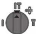
POnuJa 3a yDapHo DynpeHe BO 6eToH nn KaMeH
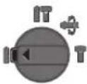
POnuJa 3a DnyueHe 6e3 yIapn BO IpBO, Metan, Kepamka IIIacTHKa KaO N 3a 3aWpaFyBaHe/0DbpyBaHe
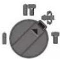
No3njuJa Vario-Lock 3a noDecyBaHe Ha
no3njujata Ha nTeTo
Bo Obaa no3njuJa, npeknHyBaOt 3a
3aInpaHe Ha ydpn/BpTeKn 9 He ce
BknOnyBa.
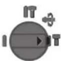
I03nuija 3a IneTyBaBe
IocTabeTo npabeoT ha BpTeHe
Co npkeHyBaOt 3a MeHyBaHe Ha npabeOTo 3a BpTeHbE 4 MoKe Da To IpomEnHe TnpabeOTo HA BpTeHbE Ha eneKTPnHnO t anapat. IOKoIky npkeHyBaOTo 3a BKJyBaBe/HckJyBaBc6 e npHTnCHAT Oba He e BO3MOxHO.

TeKa Daecho: Cbptete ro npeknhybaot 3a npabeu Ha BpTeHe 4 od DBeTe cTpaHn Do Kpa JBO no3nju

TeKaHaNeBO: CbPtTe Ro IpeKHHyBaOT 3a npaBeu Ha BpTeHe 4 OdBteCTpaHIO KpaJ BONo3nJa
PpabeoT ha BpTebe npn ydpno Dnypehe, Dnypehe nDyteBaBe cekoraw noctabyBajTe ro Ha Decen Tck.
BknyuBaBe/HckNkyuBaBe
-3a BknyyBaBe Ha eNkTpHnO T anapat npTnCHTe ro npeKHyBaOT 3a BknyyBaBe/NCKyuYBaBe 6.
-3aФнкраьeHa npeknHvBaUOT 3a BknyBaBe/HcknyBaBe,Држete rO HCTNtIpnTCHa IdoONHHTeHnO npITCHeTe Ha konyeto 3aФнкраьe5.
-3a BknyyBaBe Ha eNEKTPMHNOT anapat,OTNYWTeTFO npEKNHyBaOT 3a BkNpyBaBe/HCKNPyBaBe 6.0KOJky CTe Ro 6blKnPane npEKNHyBaOT 3a BkNpyBaBe/HCKNpyBaBe 6 HajnpBn PnHTCHETe FO HCTHOT N IOToa OTNYWTeTFO.
3a da ce 3aawtee n eheprna, Bknyybaje ro enektpnHnot anat cmoDOKONky ro Kopncntte.
IopecyBaBe Ha 6pojT Ha BptexH/ydapn
Bpojot Ha BpTeKHTe/YdApnte Ha BknyeHnT eEnKtpueH anapat MoKe Da ro perynipate 6eccteneHo, Bo3aBnCHoCT OToa KOnKy Nopaleky Ke ro npHTncHete npeKHyBaHT 3a BknyuBaBe/HcknyuBaBe 6.
CoHexHO npHTNcKaHe Ha npeKHyBaOt 3a BknyyBaBe/HcknyyBaHe 6 ce NoCTnHyBaAT Man 6poj Ha BpTeKn/YdApn. Co 3rOenMyBaHe Ha npTnCOkOT ce 3rOenMyBa H 6pojT Ha BpTeKn/YdApn.
CabaKobayek47Hb,6poj3
1000 Ckonje
E-nowa: dimce.dimcev@servis-bosch.mk
HHTepHer: www.servis-bosch.mk
Ten./paKc:02/2467610
Mo6.:070595888
OtctpaHyBaBe
EnektpnHHe anapatn, onpemaTn am6aJaxTe tpe6a da ce oCTpaHaT ha ekolooKn npfaoTnB HauHH.
He rH pPnajTe eneKtpnHnTe anapatn BO DOMaHata KaHTa 3a fY6pe!
Camo 3a 3emjH BO paAMKn Ha EY
Cnopei Ebponckata perynatna 2012/19/EU3a eeneKtpnHn n eneKtpoHcKn yepu HNBHa HauhoHnHa yNoTp6a,eneKTPnuHnte anapatni uTO ce BOH yNoTp6a Mop aOnenHO da ce cobpaat n da ce peun KInpaaT ha ekolooKN npdpTnB HaunH.
Ce 3aDpKzyBa npaBTo Ha npoMeHa.
Srpski
Uputstva o sigurnosti
Opsta upozorenja za elektricne alate
UPOZORENJE
Citajte sva upozorenja i uputstva. Propusti kod pridrzavanja upozo
Uldised ohutusjuhised
TAHELEPANU
Mechanics and Electronics Ltd. PT/SAX-ASA
298 Bojeong-dong Giheung-gu
Yongin-si, Gyeonggi-do, 446-913
Republic of Korea
080-955-0909
封
aJyjglll 1sAaiwgl aoln J
Ldawil pdoaiwl. jqlll bpoj k
Ukuiuuii. uuiuuiuuiuuiuuiuuiuuiuuiuuiuuiuuiuuiuuiuuiuuiuuiuuiuuiuuiuuiuuiuuiuuiuuiuuiuuiuuiuuiuuiuuiuuiuuiuuiuuiuuiuuiuuiuuiuuiuuiuuiuuiuuiuuiuuiuuiuuiuuiuuiuuiuui uiu uuuuuuuuuuuuuuuuuuuuuuuuuuuuuuuuuuuuuuuuuuuuuuuuuuuuuuuuuuuuuuuuuuuuuuuuuuuuuuuuuuuuuuuuuuuuuuuuuuuuuuuuuuuuuuuuuuuuuuuuuuuuuuuuuuuuuuuuuuuuuuuuuuuuuUUUUUUUUUUUUUUUUUUUUUUUUUUUUUUUUUUUUUUUUUUUUUUUUUUUUUUUUUUUUUUUUUUUUUUUUUUUUUUUUUUUUUUUUUUUUUUUUUUUUUUUUUUUUUUUUUUUUUUUUUUUUUUUUUUUUUUUUUUUUUUUUUUUUUUUUUUUUUUUUUUUUUUUUUUUUUUUUUUUUUUUUUUUUUUUUUUUUUUUU
aBwgljLlIg alnlo aIg lbo
Joo
aJgSJJ ssll aolc aJoo bdo
- aaiuiai i 1
auiuiai uaiuai uaiuai uaiuai uaiuai uaiuai uaiuai uaiuai uaiuai uaiuai uaiuai uaiuai uaiuai uaiuai uaiuai uaiuai uaiuai uaiuai uaiuai uaiuai uaiuai uaiuai uaiuai uaiuai uaiuai uaiuai uaiuauiu
:glj aJgJ gac 1sJgws Jb
jIgJlJaaJIgGgdoJI
SISgLgLsJ2012/19/EU
gJUJJgSgjjgSj
oIolaiI JgJc JgJyJyJy
duuwwgJSGSglgaoaIg
JUyjI Cwjj Booo L wuLio 0uJlu
.
.1gaa 5mu aig
jgl aJiloj li JIJIJIJIJIJIJIJIJIJIJIJIJIJIJIJIJIJIJIJIJIJIJIJIJIJIJIJIJIJIJIJIJIJIJIJIJIJIJIJIJIJIJIJIJIJIJIJIJIJIJIJIJIJIJIJIJIJIJIJIJIJIJIJIJIJIJIJIJIJIJIJIJIJIJIJIJIJIJIJIJIJIJIJIJIJIJIJIJIJIJIJIJIJIJIJIJIJIJIJIJIJ
.
w g w bJ Jg w g w w jI Jaaio .Jy J (JWgjg oJJg) 0laai (aew) y Jy Cwliog Wg w y
(ωgμw)g|s,llwjgig ojjdsj jwlsj 30ss22 wjg
uugwg CJJ0
olkiusjssjg jaa,1j0
. 10000000000000000000000000000000000000000000000000
aaw y jai sl sy s y jy jj g o j
w g jao sial a y g wg y bss ay iuy.
da jw g y jy jy (w g jl y uo s)
J L Js y s ggl qj l jg j1
g jj g jj j j j j j j j j j j j j j j j j j j j j j j j j j j j j j j j j j j j j j j j j j j j j j j j j j j j j j j j j j j j j j j j j j j j j j j j j j j j j j
jai olaawl ju w| uj |1 uj|
Iglo gogjIu lo
jLJ Laiu gW u jU uLo s Jg Uaio g S UaB g uagw Uaia UaB oJyUclalglgglai.1sUaIgawguiu jOuolu wJdulglo Ulaio gS Ua
www.bosch-pt.com
JLsL b Jg jI yI aJ gJl aJ p
p 10 g oJaiw I jb, Jy Jy Jy Jy Jy Jy Jy Jy Jy Jy Jy Jy Jy Jy Jy Jy Jy Jy Jy Jy Jy Jy Jy Jy Jy Jy Jy Jy Jy Jy Jy Jy Jy Jy Jy Jy Jy Jy Jy Jy Jy Jy Jy Jy Jy Jy Jy Jy Jy Jy J yJ yJ yJ yJ yJ yJ yJ yJ yJ yJ yJ yJ yJ yJ yJ yJ yJ yJ yJ yJ yJ yJ yJ yJ yJ yJ yJ yJ yJ yJ yJ yJ yJ yJ yJ yJ yJ yJ yJ yJ yJ yJ yJ yJ yJ yJ yJ yJ yJ yJ y
- 150suiS Cuiu (Suiu dss Jlojam g jg
- jlaia 6 uog g bgsu 6 uog g o1s uog uog uo J .uis loj .uis oJugg osu Jui Cwai S U wgi Gg kag jgl jul s jg d qg Cg .si s oiai i jil uolgs go ds
cmu/duo sssj pbi jogai
0s s gj l j1j1g 0s S wgol a J GjI Iw g dJy dJy dJy Jglw g dWg j
A
Lac slg jlaimj
4LjSJIjI
.
(Vario-Lock = pLg ∪ S Ld) pLg Cuaag
SDS-plus 14 (s) goso pai aow (og) wsgj - cclw aac cgsa aolai aal Sos
Lalaol dIwgy Jg S gS oog (lalso) Jg gS uSo
Jy jy sls s J y dla 15g jLg g J
Jy sls yilgoo oJlg g J ss OJg J
Jc g J S uuui Lg nJJ Cws. sinu J
Jsuu Lg g JJ gj Ccl CwI J
JJJ ds 15g jLg g Oss Olaew J
Jy, dy
logj jg g sio gogaa oIg jc g jg jUg jyogaa .uuu uJ Ubu w uJ cJ yg 1go ,logjS) ggs Jg Jg Jg dS Ig Jw Lg Jal bao .Siguo Oy Jy (ga Jt BaoLoo Jy Siuua Cwujf Sgl Js dS Isgo ly SJlaa yosia .ssJS
Jc wai abai JSDS-plus y jg 1j gw Jj
, gai i jz .s d jg SDS-plus a jg 1jg J
J Sao SDS-plus ay jg 0jg J
. gai jg w goc oui puiu uio cui
0siiS jusu iis baa gdo jnu duol a d s jgj
CaiIba .glgwsjgoXgac ly glgwsgac
.duw diwls
-1gJySjAoo
pIaJ dWg JJJJjI JIJIogJ
joo jui d (ij p) 15 g u Ss SDs-plus joo plai aas uis el SDs-plus a .g0 oJ
gJolw.jlG gJy jJgJy JgJy (Ugao) JjI, gJy Jy Jy Jy Jy Jy Jy (SdS-plus dW lglogil pblj w y jI jI y Jy Jy Jy. .Ju (SdS) Ugao pblj
(Sdi)gaoo pblai jilgoog (Cgagj g
pUbi uu Su JI SDS-plus 15 gJgJd aUo - Ugsa oui ci .Sis 14 (sdi s) Jgao 1
duiis dgi .Sis JgO 13 Gia! auu g u I 14
. wluu agjj sljlaiau
gaoo pblai w g jds jog (Cggi gw Egsj)(saili s)
- jzJ 0s
-1(sla)
- jlaio1j uic
gaoo pabi wu (sSoslu) uuiyogai
Juag aJb dJ 3 Jg (w gJW) jgU S -.J14 (sil s) Jgao oLaiaw g
jI jI Jg
dLs aS kdo jue g sJg j1 2jue do S
JjpoSio .siu (Sgl Jls poSio ooi Jj1
2Jue do Sos ds uis cOo Sui jIjI jIi
Ajjg0jIjJl
Jguguogj.1sJgCJJgJUSSWlI (ugj j Uu Ua) Jao oJaaJbWgJ 1
g (cag w (s) g) ah w jL J LJ EN60745-2-6 sigw o dawla s jilw siu K Uba
K = 1, 5 m / s ^ 2, a _ h = 1 7, 5 m / s ^ 2: u üüüüüüüü
K = 1. 5 m / s ^ 2, a _ h = 1 4 m / s ^ 2: LSLL, ω_ L
K = 1, 5 m / s ^ 2, a _ h lt; 2, 5 m / s ^ 2: jlgjslslggw
. K = 1, 5 m / s ^ 2, a _ h lt; 2, 5 m / s ^ 2: L _ 四
w gJ L JgW S d o W d g w j g Jd E EN 60745 dJdI W qB sS oJd Olaew J k y B Jy Jy aLao yj nJgno
wla j|g|doa bgo cLbI
EN60745-2-6 gjg j
.
EgjUogosJooA JJlA JgO abw 91 dB(A) jgO Jooaaw ly CwI Jdso
(ooaogoc)Iba uo.102dB(A)gwojgabw
K = 3 dB
1s slaowl jaij wg j
1j1. 1s laiil g a sl jiaabo oIg d i9j S J k j n jiaobo g jie cws g s ly igio I jqy .S Cui dIJI g
dsdoa gdsjg j. sis pao l js doab oos oos duw g lg osijg ci ulqdiu w dsi li, gauo da j jiaabo ls doab ,sui .gaiu
g j1j 1sly cgs j1 jolks jgsj 1jis g0j5 js deba du cwi sao ooiu .gawlaoww wj
jslac golsw
sLgS LwJyj. 1 yu yu yu yu yu yu yu yu yu yu yu yu yu yu yu yu yu yu yu yu yu yu yu yu yu yu yu yu yu yu yu yu yu yu yu yu yu yu yu yu yu yu yu yu yu yu yu yu yu yu y u
g jg g s Js So JIw g dIg G Jg Jg 10i o iu u Jj IJg g Oii S g a dUw g Cws JIw g UdS g w Jy S iS g Jg Jg Jg Jg Jg Jg
jI jI cai g iJl jI s aai I 1s g o kss 5g slj lgl j I 1u wio kijll jI jI g J .Sis Cwio u jui jI jI n jS .Sis o lai W 1uabI g jie o kws u glj s lg y Sua
jI gJlJI JogggbS JSLJlU jgss J
JGJd S JsJiJJ JJI .sJ oJlaWol
JooJy gOg SJJbA.JS JOGgBgJ Lqji
.igw
<1sloIg bua JjJlJlLg jgJ gJd
w]
iJ 1
sI JSLJSLJGACglaIglaIg
Igaijgaijgws daa !
JUcjcuiuuiuuiuuiuuiuuiuui uuuu uuuu uuuu uuuu
1 oJgao jibilf jbiin gigihjkqddam .siS sJg
sGoo Coo 《SjsslljI]jlaai Jl J I J
SLJIyIg (OpaWu) Sjssll 10jlbio .suL Go (OpaW uG) JI Sblu
4 dwlglu gblg jjI JjI dS swhbgo jL 100
clg jgi gjolbs
glo glo 15gag
aam 1
i 1
SjS|Sia
J 1s. ssi dai gds iigg s. shu Jlal l jjll jolam dai aia g Jg Jl aia g .g w o lai w Joj g Jg jk Jg jw Jp, wli (sljg g o sio
Jg g Jg Jg Jg Jg Jg Jg Jg Jg Jg Jg Jg Jg Jg Jg Jg Jg Jg Jg Jg Jg Jg Jg Jg Jg Jg Jg Jg Jg Jg Jg Jg Jg Jg Jg Jg Jg Jg
gaj. jJgj ggbj g jIj I jolkws JjI jI jSjSjSjSjSjSjSjSjSjSj
daawgdsjglguljggljg jlll 10kssu. jsi olaai jy jI s 1s g jui u c g j 1g o si 1s i 1s j g 0s w s .sin sui jil jki jis g jgs
jI bss sI aS ss oIaI IJI JI li qai
bss sI ywio bJy ss wio jji
.iiS oP sI Jg i
| I | € | |
| de | EU-Konformitätserklärgung Bohrhammer Sachnummer | Wir erklaren in alleiniger Verantwortung, dass die genannten Produkte allen einschlädigten Bestimmungen der nachfolgenden aufgeführten Richtlinien und Verordnungen entsprechen und mit folgenden Normen übereinstimmen. Technische Unterlagen bei: * |
| en | EU Declaration of Conformity Rotary Hammer Article number | We declare under our sole responsibility that the stated products comply with all applicable provisions of the directives and regulations listed below and are in conformity with the following standards. Technical file at: * |
| fr | Déclaration de conformité UE Marteau perforateur N° d'article | Nous déclarons sous notre propre responsabilité que les produits désrits sont en conformité avec les directives, règlements normatifs et normes énumérés ci-dessous. Dossier technique auprès de: * |
| es | Déclaración de conformidad UE Martillo perforador No de articulo | Declaramos bajo esta exclusiva responsabilité, que los produits nombrados cumplen con todas las dispositions correspondientes de las Directivas y los Regimientos Mentionados a continuación y está en conformidad con las siguentes normas. Documentos tínicos de: * |
| pt | Déclaration de Conformidade CE Martelo perforador N.° do produit | Declaramos sob esta exclusiva responsabilité que os produits Mentionados cumprem todas as dispositions e os regulamentos indicados e está em conformidade com as següentes normas. Documentação técnica pertencente à: * |
| it | Dichiarazione di conformità UE Martello perforatore Codice prodotto | Dichiariamo sulla mia piena responsabilità che i prodotti indicate sono conformi a tutte le dispositions pertinenti delle Direttive e dei Regolamenti elencati di seguito, nonché alle seguenti Normative. Documentazione Tecnica presso: * |
| nl | EU-conformiteitsverklaring Boorhamer Productnumber | Wij verklaren op eigien verantwoerdelijkheid dat de genoemde producten voldoen aan alle desbetreffende bepalingen van de hierna genoemde richtlijnen en verordeningen en overeenstemmen met de volgende normen. Technisch dossier bij: * |
| da | EU-overensstemmelseserklæring Borehammer Typenummer | Vi erklærer som eneansvarlige, at det beskreve Produkt er i overensstelmse med alle gældende bestemmelse i følgende direktiver og forordninger og opfylder følgende standarder. Tekniske bilag ved: * |
| sv | EU-konformitetsförklaring Borrhammare Produktnumber | Vi fökclarar under eget ansvar att de námnda produktura uppyller kraven i alla gällande bestämmer se de nedan angivna direktiven och forordningar nas och att de stämmer overens med följande normer. Teknisk Dokumentation: * |
| no | EU-samsvarserklæring Boorhammer Produktnumber | Vi erklærer under eneansvar att de nevnte Produktene er i overensstommelse med alle relevante bestemmelse i direktivene og forordningene nedenfor og med følgende standarder. Teknisk Dokumentasjon hos: * |
| fi | EU-vaatimustemmukaisuusvakuutus Poravasara Tuotenumero | Vakutamme täten, etta mainitut tuotteet vastaavat kaikkia seuraavien direktivien ja asetusten asiaankuuluvia vaatimukisja ja ovat seuraavien standarden vaatimusten mukaisia. Tekniset asiakirjat saatavana: * |
| el | Δηλωση πιστότητας EE Περιστρομίκου Μιστολέτο | Δηλώνουμε με σακλειτήμας ευθύνη, σπι τα αυαφερόμενα προδύντα αυτοτιχουνν σε λέειτις σεχεικέδιατάξεις των πίου ταυαφερόμενων σθημύν και κανονισμύν και ταυτιχονται με τα ακόλουθα προτυμα. Tekvná ψγγραφα στη: * |
| tr | AB Uygunluk Beyani Kırıci-delici Ürün kodu | Tek sorumlu olarak, tanimlanan ürünün asaqidaki)yönnetmelik ve direktiflerin geleçeri buttun hülçümlerine ve asaqidaki standartla ureygun olduguñu beyan ederiz. Teknik belgelerin bulundugu yer: * |


| C€ | ||
| pl | Deklaracja zgodnosci UEMlot udarowo-obrotowy | Oswiadczamy z pełna odpopiewiazlnoscia, ze niniejsze produkty odpopiwadajz wszystkim wymaganium ponije wyszczególniych dyrektyw i Rozporstrandze, oraz ze są zgodne z nastepujćymi normami.Dokumentacja techniczná:* |
| cs | EU prohlášení o shodéVrtaci kladivo Objednaci cislo | Prohlášujeme na výhradni zodpovednost, ze uvedeny výrobek splůnevsechna príslušnéustanoveni niže uvedenych směrnica a nárizeni je v souladus následujćím normami:Technické podklady u:* |
| sk | EU vyhlášenie o zhodeVrátie kladivo Vecné cislo | Vyhlasujeme na výhradnu zodpovednost, ze uvedeny výrobek splúna věskeypríslušnéustanovenia nižsèu uvedenych smernic a náriadeni je v súlade s nasledujúcimi normami:Technické podklady má spolocnost:* |
| hu | EU konformitàsi nyilatkozafFúrókalapács Cíkszám | Egyedüli felǒséggel kijelentjuk, hogy a megnevezét termékek megfelelnekaz alábbiakban felsorolára kerülö irányelvek és rendeletek valamennyi idevázó elöirásainak és megfelelnek a követkeź szabványoknak.Muszaki dokumentumok megörzési pontja:* |
| ru | 3aavbene no cooTBeTCTBn ECPerφopatop Tovapnbý N° | Мы заувлелем по haу щедноюу OTВETCTBENHOCTb, чу доцьаньплесудкгу býteч STYSTYSTYSTYSTYSTYSTYSTYSTYSTYSTYSTYSTYSTYSTYSTYSTYSTYSTYSTYSTYSTYSTYSTYSTYSTYSTYSTYSTYSTYSTYSTYSTYSTYSTYSTYSTYSTYSTYSTYSTYSTYSTYSTYSTYSTYSTYSTYSTYSTYSTY |
| uk | 3aavba pro bivnoibidnctb CCPerφopatop Tovapnbý HOMep | Mizuzaaybne mo πd haуоу undhoocobovу býindobädaNBICHTB PAVONOBIDAOHT YCM UHNHIM PONOKHEHM HNUEO3HAEHIX DINOPEKTHB IPOZPONJXHb, a TAKOXXHNEO3HAEHIX HOPM.Texhunecká doKoymentaučna xpanHTCya:* |
| kk | EO cōiKečtik maflumdamacbIPerφopatop Θhim Hemipi | Θžkaayankerpūniliknen 6i3 atalfahн émimder TEmende JxtsBaIFANHIN DEPEKTKAcapam Men karlbiktardbn TnICTI KAFndaIapblya caiKeCTIRH XaHe TEmenderi HOPMaIAPRa cai EkenH bldipemiz. |
| ro | Declarataie de conformitate UECiocan rotopercutur Numár de identificare | Declarãm pe proprie raspundere cà produselementionate corespend tuturord disposztijlor relevante ale directivelor ŞI reglementärer enumerate in cele ce urmeažá ŞI sunt in conformitate cu urmätoarele standarde.Documentatie tehnica la:* |
| bg | EC DeKaparacnla 3a cSbTBeTCTBnEPφopatop Katanojexn HOMep | С пьлна отвогорoctные дeКapариаме, чу поочених подуктуговату OTOBAPRnHa BCNUKN BAVUKNI H3NCKBAHNA NaДePKEKTHBte Hpa3Npepe6bnteNo-dolny i cSbTBeTCTBa Ha CleNdHte CTAndaprtN.Texhunecka doKoymentaučna pri:* |
| mk | EU-NsJBa 3a coobpa3nOCTChekAnu 3a dvnuebe Bioj Na den/aprTkn | Coцelnoсha освогорost Ильавуме, DeKa ONIIshanite РожибODиce BoCorglacHTCnCepeVeBANTNHa DCIOpeBHTNHe Na ClendHite PerynatBnИпрпси и сBo CorglacHTCnCe CToBcTACHTCnCSeLDHNTe HOpM.N.Texhunka doKoymentaučna jau:* |
| sr | EU-izjava o usaglasenostiBusilica ČekićBroj predmeta | Na sopstvenu odgovornost izjavljemu, da navedeni proizvodi odgovaraju swim doticiñim odredbama naknadno navedenih smernica u uredaba i da su skladu sa sledecim standardima.Tehnička dokumentacija kod:* |
| sl | Izjava o skladnosti ESVrtalno kladivo Številka artikla | Izjavljamo pod izključno odgovornostjo, da je omenjen izdelek v skladu z vsemirelevantnimi dolocii direktiv in uredb ter ustreza naslednjim standardom.Tehnična dokumentacija pri:* |
| hr | EU izjava o skladnostiUdarna busilica Kataloški br. | Pod punom odgovornosću izjavljemu da navedeni proizvodi odgovaraju swim relevantim odredbama direktiva i propisima navedenima u nastavku i da su skladni sa sledecim normama.Tehnička dokumentacija se moze dobiti kod:* |
| et | EL-vastausdeklaratsoonPuurvasar Tootenumber | Kinnitame ainuvastutajatena, et nimetatud tooted vastadov järgnevalt loetud direktiviide ja märuste kokiidele asjaomastele nõuetele ja on kooskolas järgmiste normideg.Tehnilised dokumendid saadaval:* |


| III | € | ||
| Iv | Deklaracja par atbilstūb EK standartiem | Mś ar pilnu atbildibu pazinojam, ka šeit aplūkotte izstrādājumi atbilst visiem tālák minētajās direktīvās un ríkojumos ietvertajām saistosajām nostādnēm, kā ār sekojošiem standartiem. | EN 60745-1:2009+A11:2010 |
| Perforators | Tehniskā dokumentācija no:* | ||
| It | ES atitikties deklaracija | Atsakingai pareiškiame, kad išvardty gaminiali atitinka visus privalomus Žemiau nurodytu direktvyū ir reglamenti reikalavimus ir šiuos standartus. | EN 60745-2-6:2010 |
| Perforatorius Gaminio numeris | EN 55014-1:2006+A1:2009+A2:2011 | ||
| EN 55014-2:1997+A1:2001+A2:2008 | |||
| EN 61000-3-2:2014 | |||
| EN 61000-3-3:2013 | |||
| EN 50581:2012 | |||
| BOSCH *Robert Bosch Power Tools GmbH (PT/ETM9) 70538 Stuttgart GERMANY | |||
| Henk Becker Helmut Heinzelmann | |||
| Executive Vice President Head of Product Certification Engineering | |||
| i.v. h·w· | |||
| Robert Bosch Power Tools GmbH, 70538 Stuttgart, GERMANY Stuttgart, 01.01.2017 | |||

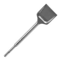
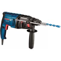
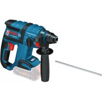
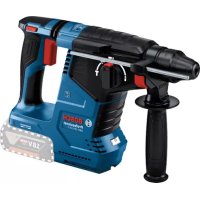
- GBH 2400 Professional
- BOSCH
- General Power Tool SafetyWarnings
- WARNING
- Save all warnings and instructions for future reference.
- | English
- Work area safety
- Electrical safety
- Personal safety
- Power tool use and care
- Service
- Hammer SafetyWarnings
- English|13
- Product Description and Specifications
- Intended Use
- Product Features
- Technical Data
- Noise/Vibration Information
- Wear hearing protection!
- 14|English
- Assembly
- Auxiliary Handle
- Changing the position of the auxiliary handle (see figure A)
- Adjusting the Drilling Depth (see figure B)
- Selecting Drill Chucks and Tools
- Changing the Key Type Drill Chuck
- Mounting the Key Type Drill Chuck (see figure C)
- Inserting the Key Type Drill Chuck (see figure C)
- Removing the Key Type Drill Chuck
- Changing the Tool
- Inserting SDS-plus Drilling Tools (see figure D)
- Removing SDS-plus Drilling Tools (see figure E)
- Inserting Drilling Tools without SDS-plus
- Removing Drilling Tools without SDS-plus
- Dust Extraction with the Dust Extraction Attachment (Accessory)
- Mounting the Dust Extraction Attachment (see figure F)
- Adjusting the Drilling Depth on the Dust Extraction Attachment (see figure G)
- Operation
- Starting Operation
- Setting the operating mode
- Reversing the rotational direction
- 16|English
- Switching On and Off
- Setting the Speed/Impact Rate
- Overload Clutch
- Working Advice
- Changing the Chiselling Position (Vario-Lock)
- Inserting Screwdriver Bits (see figure H)
- Maintenance and Service
- Maintenance and Cleaning
- After-sales Service and Application Service
- www.bosch-pt.com
- Great Britain
- Ireland
- Australia, New Zealand and Pacific Islands
- Republic of South Africa
- Customer service
- Gauteng - BSC Service Centre
- KZN - BSC Service Centre
- Western Cape - BSC Service Centre
- Bosch Headquarters
- Disposal
- Only for EC countries:
- Français
- Bortskaffelse
- Avfallshantering
- Endast for EU-lander:
- Emloytookkaiepyaaleiwv
- Alambdayn ypavacwou took
- SuvapoloyonTou ypavaZtouTook (Bale Eikova C)
- Apaipean Tou ypavaawou took
- TonoBcTnO npyaleoiu xupic SDS-plus
- Apaiaeconepyaaleiouxwopic SDS-plus
- EAnnvika171
- Avappoyno e Saugfix (e16iko eApTmu)
- Sigma oynou Saugfix eKova F
- Pouon Tou boudoc konic o Saugfix (Bene cikova G)
- Pouan ap0oouotpovkpooew
- EuMaektnc unepopropns
- YnobeiEicepyaiaC
- AALLayntgEoCkalemuou(Vario-Lock)
- TOnoTeHnKarouaBolaouov(BeneEkovaH)
- Euvtnponk kal Service
- Luvtnpnonkkaqapiaooc
- Service kal npoxn oupoulovxphons
- EAAaδa
- Türkçel 73
- Anoupon
- Movi yia xwpec tnc EE:
- Türkce
- Güvenlik Talimati
- Elektrikli El Aletleri icin Genel Uyar Talimati
- UYARI
- SDS-plus'suz ucin cikarilmasi
- IpeuehB KpHTnueckHX OTka3OB N OwH6OuHbIe DeHCTBnepcoHana Hnn Nnbl3OBaTeN
- Kpntepnn npedenbhbix cctoHH
- THHn nepnouhoctb texhueckoro 06cnyxhaHH
- XpaHHeHne
- TpaHcnpTnpoBka
- Yka3aHnno 6e3onachoctn
- 06une yka3aHnno TexHnke 6e3onacHOCTn nna 3NeKtpOHnCtpymENTOB
- IPOUHTHe Bce yka3aHHN HNCTpyKuHn No TEHXnke
- CoxpaHnIe 3TH HnCTpyKuHH yKa3aHnN dnn 6yduero HCNoB3OBAHn.
- Be3onachoctb pa6oeryo MecTa
- 3neKtpo6e3onacHocTb
- Pycckn103
- Be3oNaChocThnOdei
- PpmeHne 3nEeKtpoHHcTpyMeHTa n6paueHne c HMM
- CepBnC
- Yka3aHnno TExHnke 6e3onacHocTH nI npOpaTopoB
- 104|Pycckn
- Onncahne npodykra n ycnyr
- PpMHMeHHeNoHa3NaeHHo
- H306paXeHHbIe coCTaBbIe qactn
- TexHHueckne daHHbe
- Pycckn105
- C6opka
- DononHntenbHaaykoTka
- TobopoTdoonHHTenbHoI pyKoTKn (cm.pnc.A)
- HacrpoKa rny6nHb cBepLeHHa (cm.pnc.B)
- Bb6op cBeprnHbHoro natpoHa HnHcTpymeHa
- Cmeha natapona c 3y6uatbIM BEHc0m
- YCTAHOBKa CBePnHbHOro NaTPOHa C3y6aTbIM BEHcOM (CM.PNC.C)
- YCTAHOBKa nAtpoHa C 3y64aTbIM BEHcOM (CM.PnC.C)
- Chrthe npohc3y6aTabm Benuom
- 3aMeHa pa6oery Hnctpymenta
- 106|Pycckn
- YcTaHOBka pa6oOero HnCTpyMeHTa SDS-plus (cm.pnc.D)
- CHTne pa6oeryo Hnctpymenta SDS-plus (cm.pnc.E)
- YctahOBka pa6oHx HnCTpymEtOB 6e3 SDS-plus
- Chrthe pa6oHx HnctpymEtOB 6e3 SDS-plus
- Otcoc nbInc Saugfix (npHaIeXHocTH)
- YcTaHOBka yCtpoHCTBa Saugfix (cm. pnc.F)
- YCTAHOBKa rny6HbI CBepneHHa yctpoNCTBe Saugfix (CM.pnC.G)
- Pa60Ta c HcHctpyMeHTOM
- BkIIOUeHHe 3NeKTPoHHCTpyMeHaTa
- YctaHOBkapeXHMa pa6oTbI
- Pycckn107
- YcTaHOBKa HAnpaBHeNn BpaSeHn
- BkIIOueHHe/BbIKIOueHHe
- YctaHOBKa uHcna O6oPoTb H yIapOB
- IpeOxoPAnHTeBnaMyΦTa
- Yka3aHnno npHMeHeHHIO
- H3MeHenHe NoIoxKeHHa 3y6nla (Vario-Lock)
- YCTAHOBKA 6HTOB (CM.PHC.H)
- Texo6cnyxHBaHne H cepBHC
- TexobcnyKmbaHne n ouhctka
- 108|Pycckn
- CepBn KOncynbTHpObaHne Ha npedmet nnonb3OBaHH npodykun
- Длретиа: Pocca, Benapycb, Kaaxctan, Ykpanha
- Pocchra
- TolboKoIaI cTpaH-ueHOB EC:
- yKpaIHcbka
- Bka3iBkn 3Texhikn 6e3neKn
- TONEPEKEXEHHA
- Be3neKaHa p0604Omy Micui
- EneKtpnHa 6e3neKa
- Be3neKa IIODei
- IpaBnblbe NOBdoJxehH Ta KOpNctyBaHH eneKtponpnaadam
- 110|YkpaIhcbKa
- Cepbic
- Bka3iBkn 3 texhikn 6e3neKn dna MONOTKIB
- BnMaHHpo6Ouxinctpymentib3SDS-plus (nB.mAe.E)
- BctpomnHnn po6ounx ihctpymentrib 6e3 SDS-plus
- BnMaHna po6Oux iNcTpymetTb 6e3 SDS-plus
- BicmokrybaHHnny 3a donomoroio Saugfix (npna)
- MoTHaX Saugfix (mB.Man.F)
- YkpaHcbka 113
- BctahOBHeHHrH6HHCBepDHeHHHa Saugfix (nVB.mA..G)
- Po6ota
- Ipoatokpo60tn
- BctahOBHeHHpeXmmypo60TH
- BctahOBHeHHHaHnPmkyo6epTaHHa
- BMHKaHHBMMKahH
- Hactpoobannkibkocti 6eptrib/kinkbocyt yaprib
- 3ano6ixha myfTa
- 114|YkpaIhcbKa
- Bka3iBkn 0o0p060tn
- 3mieHHH noIoxeHH pizu (Vario-Lock)
- BCTPOMHnH6IT (DnB. Man. H)
- Texhiue 06cnyrobyBaHHaicepBic
- Texhiehe 06cIyroBvBaHH i ouHneHH
- Cepbic Ta HadaHHa KOHCyIbTauii 0oO BnKOpNCaHHa npodykii
- YkpaHa
- Ytniiaui
- Пишдя Край EC:
- Ka3aKa7a | 115
- Ka3aKwa
- Ehimi nai danany Mep3imi
- Kb3MeTKeHeme NaDanaHyubihhKaTeiKTEpi MeiTeH bHy ce6entepinH ti3imi
- Uekri Kny bEnrinepi
- Kb3MeT KepeCy Ty pI MeH xiniriri
- CaKray
- TacbImaay
- Kayinci3ik HycKaynapbI
- 3NeKtp KypanDapbHbH Xannbl Kayinci3dk HcykaynbIKtapbl
- ECKEPTY
- BonaawKxMblctap yuiH kayinci3dk HycKaynbkTapbi Me h eceptnenepi caKan KObbl3.
- XyMbIcOpbHbHbKayinci3di
- 3nektkayinci3iri
- Aaamap kayinci3diri
- 116|Ka3akwa
- UybinKHeDipinDeyypaIbIaknapaT
- 118|Ka3aKa7a
- XnHay
- Kcbimua Tytka
- KocbImuayTKaHbI aybIKbity (A cypetin KapaHb3)
- Bypfnbain Tepehdirn opnaty (B cypetin Kapaiba)
- Bypfbinyatpohmbmehacnantapdbt Taay
- Ticti Toxik6yprfbnay natohbin anImactbipy
- Ticti taekix 6yfbnay natpohbiH ophaty (C cypetih kapaht3
- Ticti Toxik 6yfbinay natpohbuH opHaty (C cypetih kapaHb3)
- Ticti Toxik 6yprbinay natoPohbH wblfapy
- Kymbic Kypanbih aybictbipy
- SDS-plus 3nektp KypanbH naiDanaHy (DCypetIH kapaHbI3)
- SDS-plus anmanbi-canmanbi acna6bH wbfapy (E cypetin kapaht)
- SDS-plus-c3 anMaNbI-canMaNbI acnTapDbI opHaty
- Ka3aKa7a119
- SDS-plus-ci3 anMaIbI-canMaIbI acnTapDbI weu
- Saugfix Mehen uahcopy (kepek-kaapakTap)
- Saugfix ophaty (F cypetin kapaib3)
- Bpyfnay Tepehdirn Saugfix-Te pettey (G cypetin Kapaht)
- PaiandaHny
- Taindanahya eHdpy
- Painanany typin opnaty
- AHHany 6aftbIbH opHaTy
- 120|Ka3akwa
- Kocy/ewipy
- AHHaHbIMdap/kArfCaNbIHpeTey
- Kopraybiw XanFactbipfbiw
- Paindany Hycaynapbi
- Keckiw KannbH e3repy (Vario-Lock)
- BypaHa yuTbIKTapbIH opHaty (HCypTeiKapaHb3)
- TexHnKaIbIK KyTIm KxHe Kbl3MeT
- KbI3MeT KepcTey KHe Ta3anay
- Tytbinybifa KbI3MeT Kepcety XeHe naJdanaHy Kehectepi
- Ka3aKCTAH
- Kedere kapaty
- Tek KaHa EO eNdepi ywiH:
- Româna
- Be3o1aceH haunHa pa60Ta
- 128|Блгарский
- PnKJINBO OTHOWeHne KbM eNeKTpOHcTpymeHTHe
- PoiDbpxkane
- Yka3aHn 3a 6e3oNa cha pa6oTa c KpbTauh
- Onncahne Ha npodykTa H Bb3MOX-HOCTHTe My
- BbIrapckn|129
- IpeHa3HaueHHe Ha eKtpOnHcTpymeHa
- H3o6pa3eHH enemeHTn
- Hhopmaqna 3a n3buaBn Wym Hb6paun
- TexHHueckn daHHN
- 130|bblrapckn
- H360pHa natapoHHnka Hpa6oTHHTe HNCTpyMeHTH
- CmHa Ha nataPonHHka cbc 3b6eH BHeHeu
- MoHTHpaHe Ha nataPOHHKa cbc 3b6eH Beneu (BHXTeΦnC.
- MoHTnpaHe Ha nataPOnHHK cbc 3b6eH Beneu (BHXTe prr. C)
- DemOHmPnapeHa nataPOnHHK Cbc 3b6eH Beneu
- CmHa ha pa60THHn HnCTpyMeHT
- IocTbAHe Ha pa60Te HnHcTpymEt c onaWka SDS-plus (BmKTe pHr.D)
- BbIraPckn131
- H3BaXdaHe Ha pa6oTe HnCTpyMeHT c onaWka SDS-plus (BHXTe pHr. E)
- Noctabare Ha pa60THH HcTpymeHTn 6e3 onaKa SDSplus
- N3BaXdaHe Ha pa6oTHH HcTpyMeHTn 6e3 onaWka SDSplus
- Ipaoxoyabane c npctabkata 3a npaxoyabane (DonbHnTeHNO npncnoc6neHne)
- Nnyctpaunja Ha KOMNOHEHTN
- HΦopmaunn 3a6yaba/Bn6paunn
- | MaKeJoHcKn
- Texnukn noataoun
- MOHTAXA
- DonolnHtEnHa Dpuka
- Cbptete ja dononnontenhata npka (BmH cnna A)
- IopdecyaBaHe Ha dna6oounHa hyuyebe (BnHc nNka B)
- BnpaBe Ha rnaBa 3a dynuebe n anat
- 3aMeHa 3aIueCTata rnaBa 3a dynueHe
- MoHTnpaHe Ha 3anuectata rnaBa 3a dynuehe (BnDcnKa C)
- BmTeHyBaBe Ha 3aIueCTa Ta INaBa 3a DynueHe (BnD CnKa C)
- M3BaTe ro SDS-max anaTOT 3a BMETHyBaHe (BmH CnKa E)
- CTabaBe Ha anat 3a BMETHyBaBe 6e3 SDS-plus
- Baedehe Ha anaTOT 3a BmETHyBaBe 6e3 SDS-plus
- BumkyBaBe Ha npab co Saugfix (onipema)
- MoThnpaIbe Ha Saugfix (BnDn cInkaF)
- NoecyBahe Ha dna6ouHHata Ha dyuueHe Ha Saugfix (BnDn CnKa G)
- Ynortpe6a
- CTabaBe BO ynoTpe6a
- 138|MaKeJIoHcKn
- PoeecyBaBe Ha NaHnHOT Ha pa6ota
- IocTabeTo npabeoT ha BpTeHe
- BknyuBaBe/HckNkyuBaBe
- IopecyBaBe Ha 6pojT Ha BptexH/ydapn
- OtctpaHyBaBe
- Camo 3a 3emjH BO paAMKn Ha EY
- Srpski
- Uputstva o sigurnosti
- Opsta upozorenja za elektricne alate
- UPOZORENJE
- Uldised ohutusjuhised
- TAHELEPANU
- 封
- Joo
- aJgSJJ ssll aolc aJoo bdo
- uugwg CJJ0
- olkiusjssjg jaa,1j0
- Iglo gogjIu lo
- cmu/duo sssj pbi jogai
- Lac slg jlaimj
- (Vario-Lock = pLg ∪ S Ld) pLg Cuaag
- Lalaol dIwgy Jg S gS oog (lalso) Jg gS uSo
- pIaJ dWg JJJJjI JIJIogJ
- jI jI Jg
- wla j|g|doa bgo cLbI
- jslac golsw
Brand : BOSCH
Model : GBH 2400 Professional
Category : Hammer