GHT 130 Professional - Hammer BOSCH - Free user manual and instructions
Find the device manual for free GHT 130 Professional BOSCH in PDF.

| Product Type | Floor Removal Cart |
| Brand | Bosch |
| Model | GHT 130 Professional |
| Reference | 1 600 A02 WMO |
| Dimensions (max height) | 1100 mm |
| Dimensions (max length) | 780 mm |
| Dimensions (min height) | 640 mm |
| Dimensions (min length) | 1000 mm |
| Dimensions (width) | 570 mm |
| Weight (without hammer) | 27 kg |
| Number of working positions | 5 |
| Main materials | Steel |
| Intended use | Only with Bosch GSH 16-28 or GSH 16-30 demolition hammer |
| Delivery contents | Chassis, handle, 2 transport wheels, hammer mounting kit, instruction manual |
| Maintenance | Regularly oil the Bowden cable; grease the pivot axis via the grease fitting |
| Safety | Wear protective equipment (safety glasses, hearing protection, mask); check fastenings before use |
| Spare parts | Available from Bosch after-sales service |
| After-sales service | Bosch customer service: 09 70 82 12 26 (France) |
| Repairability | Repair possible via SAV DIRECT at www.bosch-pt.fr |
Frequently Asked Questions - GHT 130 Professional BOSCH
User questions about GHT 130 Professional BOSCH
0 question about this device. Answer the ones you know or ask your own.
Ask a new question about this device
Download the instructions for your Hammer in PDF format for free! Find your manual GHT 130 Professional - BOSCH and take your electronic device back in hand. On this page are published all the documents necessary for the use of your device. GHT 130 Professional by BOSCH.
USER MANUAL GHT 130 Professional BOSCH
natural_image
Mechanical vehicle chassis with wheels and suspension components (no visible text or symbols)4
natural_image
Side view of a mechanical cart or pulley system with wheels and a handle, no visible text or symbols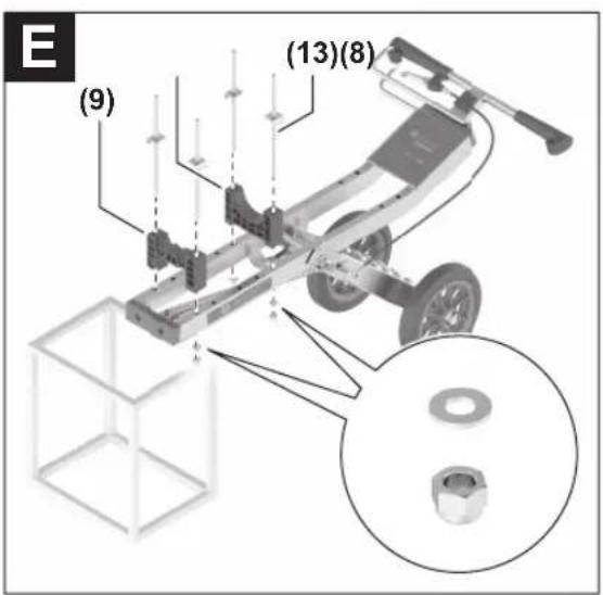

Deutsch
Sicherheitshinweise

www.bosch-pt.com/serviceaddresses
Entsorgung
Read all safety and general instructions enclosed with the Floor Removal Cart and the hammer being used. Failure to observe the safety and general instructions may result in electric shock, fire and/or serious injury.
Keep all the safety and general instructions for future reference.

Never reach inside the area of the folding mechanism. You could injure yourself.


▶ Wear additional personal protective equipment such as protective glasses, hearing protection, a breathing mask and safety footwear.
▶ Ensure that the hammer is switched off before you connect or disconnect the mains plug. Only connect the mains plug for operation.
▶ Pull the plug out of the socket before carrying out any work on the power tool.
▶ Only fit the hammer on the trolley when the trolley is positioned on a level surface. The trolley may move in an uncontrolled manner and the hammer may fall down. This poses a risk of injury.
▶ Ensure that the hammer is fitted correctly and all of the screws are tightened before starting work or before transporting the trolley with the hammer fitted. Otherwise the hammer could move in an uncontrolled manner. There is a risk of injury to you.
Before fitting the hammer to the trolley and before each use of the fitted hammer, always check the mains connection cable for any damage. When operating the fitted hammer, ensure that you do not damage the mains connection cable. Have any damaged mains connection cables replaced by an authorised Bosch after-sales service centre. If a damaged mains connection cable makes contact with the trolley, it can cause an electric shock.
▶ Only use application tools that are permitted in the operating instructions of the hammer.
Do not leave the trolley unattended when the hammer is fitted and do not transport it with the hammer switched on. Unintentional movement of the trolley can activate the hammer's impact function.
▶ Only use the hammer fitted on the trolley on a level surface and only ever with wheels fitted on both sides. Otherwise the trolley can fall over.
▶ Ensure that the fitted hammer is stored in an upright position after use. This makes the trolley more visible and prevents potential accidents.
Product Description and Specifications
Please observe the illustrations at the beginning of this operating manual.
Intended Use
The Floor Removal Cart is intended for ergonomic support when removing floor coverings like tiles, vinyl or wood with a demolition hammer. It bears the weight of the demolition hammer and enables a uniform working angle during floor work.
The Floor Removal Cart may only be used with the Bosch GSH 16-28 or the Bosch GSH 16-30.
Product Features
The numbering of the product features shown refers to the illustrations of the product on the graphic pages.
(1) Lubricating nipple
(2) Trolley frame
(3) Angle adjustment unlocking lever
(4) Protective bar
(5) Handle section
(6) Cable suspension
(7) Transport wheel
(8) Handle receptacle fastening block
(9) Tool holder fastening block
(10) Top panel
(11) Splint for transport wheel
(12) Transport wheels fastening set
(13) Threaded rod with tab
(14) Bosch GSH 16-28 and Bosch GSH 16-30 fastening set
(15) Handle section screw
(16) Handle section mounting plate
(17) Adjustment screw for angle adjustment
(18) Bowden cable lock nut
(19) Bowden cable adjustment screw
Technical Data
| Floor Removal Cart GHT 130 | |
| Article number | 1 600 A02 WMO |
| Number of possible work positions | 5 |
| Dimensions | |
| - Height (highest position) mm 1100 | |
| - Length (highest position) mm 780 | |
10 | English
Floor Removal Cart GHT 130
| - Height (lowest position) mm 640 | |
| - Length (lowest position) mm 1000 | |
| - Width mm 570 | |
| Approx. weight (without demolition hammer) | kg 27 |
Values can vary depending upon the product and are subject to application and environmental conditions. For further information www.bosch-professional.com/wac.
Assembly
Items Included and Assembly Tool

See the list of items included at the start of the operating manual.
Carefully remove all parts of the trolley included in the delivery from their packaging. Remove all packing material.
Check to ensure that all the parts listed below have been supplied before assembling the trolley:
- Trolley frame (2)
- Handle section (5)
- 2 transport wheels (7) with corresponding fastening set (12) (4 washers and 4 splints)
- Demolition hammer fastening set (14) consisting of: 1 top panel (10), 2 handle receptacle fastening blocks (8), 2 tool holder fastening blocks (9), 4 M10 threaded rods (13), 4 star grip nuts, 8 washers, 4 spring lock washers and 4 lock nuts
You also need the following tools for assembly (not among the items included):
- Open-ended spanner 19 mm
- Open-ended spanner 17 mm
- Pliers
- Hex key 2 mm
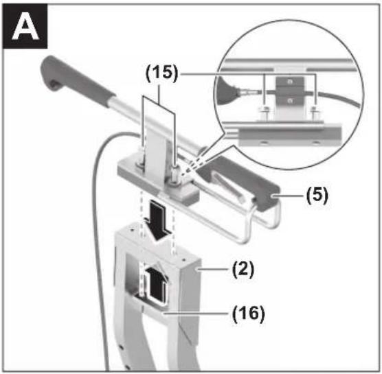
Fitting the Handle Section (see figure A)
Loosen the screws (15) on the handle section with an open-ended spanner of 19 mm until you can remove the mounting plate (16).
Place the handle section (5) on the top end of the trolley frame (2). Place the mounting plate (16) onto the screws (15) of the handle section from below, and tighten the screws (15).
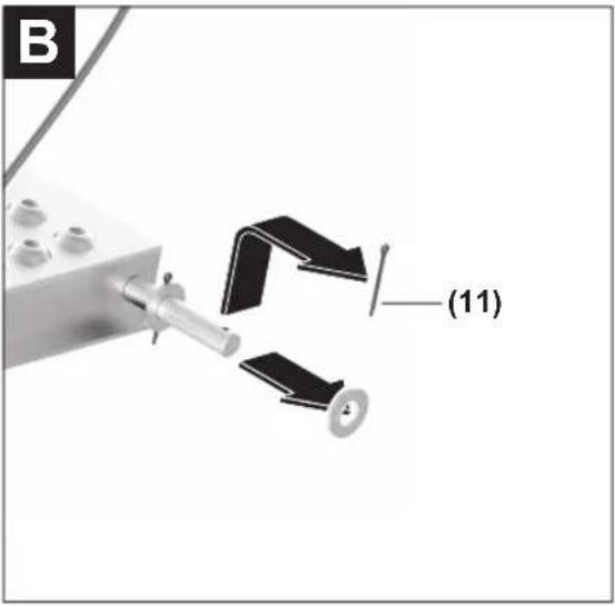
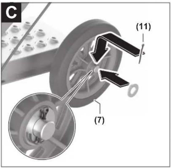
Fitting the Transport Wheels (see figures B-C)
Remove the prefitted outer splint and the outer washer on both ends of the wheel axle.
Push one transport wheel (7) each onto the wheel axle. Put the outer washer back on at each end.
Push one splint (11) through the outer cross hole in the wheel axle in each case, and bend it to secure the transport wheel.
Fitting the Demolition Hammer (see figures D-H)
Only carry out the assembly on an even, horizontal surface. Remove the carrying handle of the demolition hammer before assembly. Please refer to the operating instructions for the demolition hammer.
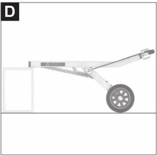
Image D:
- Set the lowest working angle (see "Setting the Working Angle", page 11) on the trolley.
- Place the bottom end of the trolley frame on a stable surface of the appropriate height, so that the surface area for the demolition hammer is aligned horizontally.
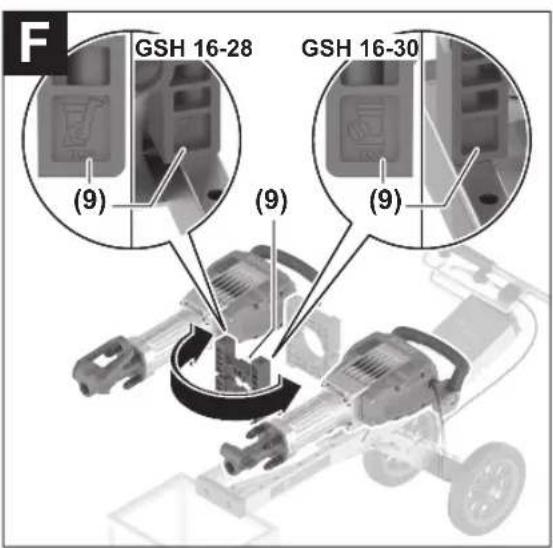
Images E-F:
- Place a handle receptacle fastening block (8) on the uppermost frame slot of the trolley.
- Place a tool holder fastening block (9) on the bottom-most frame slot of the trolley. Turn the fastening block as shown in figure F, in a way that's appropriate for the demolition hammer that's meant to be used.
- Put one threaded rod (13) each through the ends of the fastening blocks. The tabs of the threaded rods must point outwards.
- Put one washer and one lock nut each - from the demolition hammer fastening set (14) - onto the bottom end of the threaded rods. Loosely tighten the lock nuts with an open-ended spanner of 17mm .
Image G:
- Place the demolition hammer on the fastening blocks so that the coil spring damping of the demolition hammer is in the recess of the tool holder fastening block (9). Ensure that the lock bolt and the retaining bracket on the tool holder of the demolition hammer remain accessible when the tool is changed later. GSH 16-28: Open the retaining bracket.
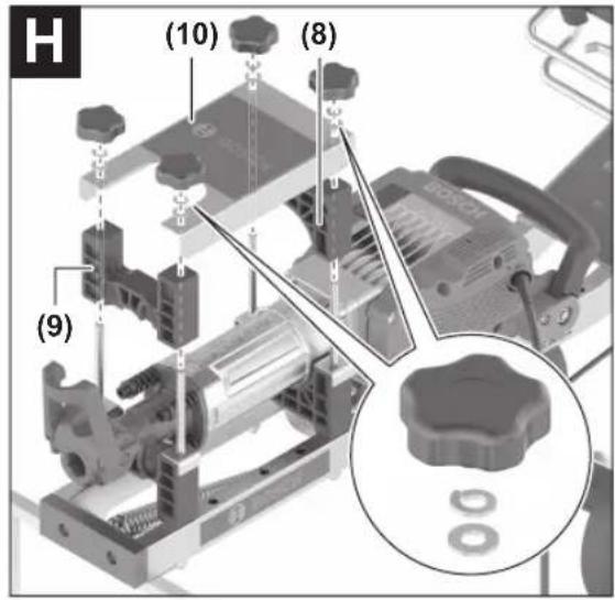
Image H:
- Place the second handle receptacle fastening block (8) on the top threaded rods, and the second tool holder fastening block (9) on the bottom threaded rods (at the same orientation as the bottom tool holder fastening block (9)). Push both blocks onto the demolition hammer as far as they will go.
- Place the top panel (10) onto the threaded rods with the recess over the tool holder.
- Tighten the locking nuts on the bottom end of the threaded rod with an open-ended spanner of 17 mm.
- Put one washer and one spring lock washer each - from the demolition hammer fastening set (14) - onto the top end of every threaded rod.
- Put one star grip nut each – from the demolition hammer fastening set (14) – on every threaded rod and tighten it well.
Hang the cable of the demolition hammer in the cable suspension (6) at the handle.
Read and observe the demolition hammer operating instructions for the assembly of the application tool in the demol-
tion hammer.
GSH 16-28: Pivot the tool retainer of the tool holder as far as it will go at the tool holder fastening block (9) to lock the application tool in place.
Operation
Setting the Working Angle
Relieve the locking mechanism of the angle adjustment before adapting the working angle by slightly lifting the handle of the trolley. Then pull the unlocking lever (3) of the angle adjustment to release the locking bolt.
Raise or lower the trolley to the required working height. Let go of the unlocking lever (3). Ensure that the locking bolt of the angle adjustment clicks securely into place.
Working with the Demolition Hammer
Before switching on the demolition hammer, check:
- That the trolley is undamaged and all screws are firmly tightened,
- that the demolition hammer is firmly bolted to the trolley and cannot be moved in the attachment,
- and that the application tool is fitted correctly and locked securely.
Set the required working angle.
Switch on the demolition hammer.
Make sure when working that neither the demolition hammer nor the application tool overheats.
For more information about working with the demolition hammer, refer to the operating instructions of the demolition hammer.
Transport
▶ If necessary, carry the trolley with fitted hammer with the help of another person. This will allow you to avoid injury.
Maintenance and Service
Maintenance and Cleaning
Lubricate the Bowden cable of the angle adjustment regularly with a little penetrating oil.
The pivot axis can be greased using the lubricating nipple (1).
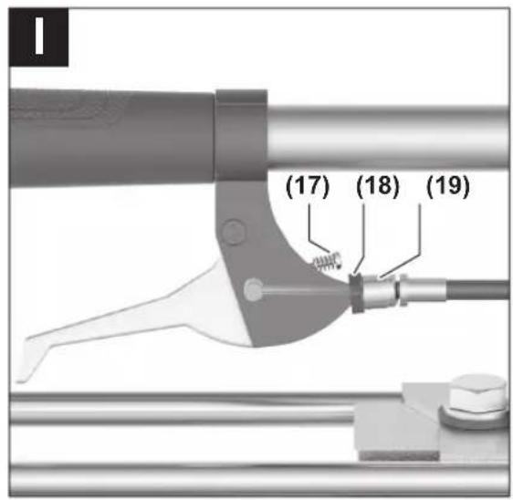
Readjust the Bowden cable of the angle adjustment if the locking bolt of the angle adjustment can no longer be securely loosened (see figure I):
- Ensure that the Bowden cable is not kinked.
- Loosen the lock nut (18) with pliers.
- Set the length of the Bowden cable with the adjustment screw (19).
- Retighten the lock nut (18).
- Tighten the adjustment screw (17) with a hex key of 2 mm, in order to eliminate play from the Bowden cable.
Please note when doing so that a little play at the Bowden cable is normal.
After-Sales Service and Application Service
Our after-sales service responds to your questions concerning maintenance and repair of your product as well as spare parts. You can find explosion drawings and information on spare parts at: www.bosch-pt.com
The Bosch product use advice team will be happy to help you with any questions about our products and their accessories.
In all correspondence and spare parts orders, please always include the 10-digit article number given on the nameplate of the product.
Great Britain
Robert Bosch Ltd. (B.S.C.)
P.O. Box 98
Broadwater Park
North Orbital Road
Denham Uxbridge
UB 9 5HJ
At www.bosch-pt.co.uk you can order spare parts or arrange the collection of a product in need of servicing or repair.
Tel. Service: (0344) 7360109
E-Mail: boschservicecentre@bosch.com
You can find further service addresses at:
www.bosch-pt.com/serviceaddresses
Disposal
Trolleys, accessories and packaging should be recycled in an environmentally friendly manner.
Ensure that the spring of the height adjustment is in a relaxed state before you dispose of the trolley.
Français
Robert Bosch (France) S.A.S.
www.bosch-pt.com/serviceaddresses
www.bosch-pt.com/serviceaddresses
Eliminação
www.bosch-pt.com/serviceaddresses
Smaltimento
www.bosch-pt.com/serviceaddresses
Afvalverwijdering
Bosch Service Center
Telegrafvej 3
2750 Ballerup
På www.bosch-pt.dk kan der online bestilles reservedele eller oprettes en reparations ordre.
Tlf. Service Center: 44898855
Fax: 44898755
E-Mail: vaerktoej@dk.bosch.com
www.bosch-pt.com/serviceaddresses
Bortskaffelse
Bosch Service Center
Telegrafvej 3
2750 Ballerup
Danmark
Tel.: (08) 7501820 (inom Sverige)
Fax: (011) 187691
www.bosch-pt.com/serviceaddresses
Avfallshantering
www.bosch-pt.com/serviceaddresses
Deponering
www.bosch-pt.com/serviceaddresses
Hävitys
www.bosch-pt.com/serviceaddresses
Απόσυρση
www.bosch-pt.com/serviceaddresses
Tasfiye
Robert Bosch Sp. z o.o.
www.bosch-pt.com/serviceaddresses
Utylizacja odpadów
Bosch Service Center PT
K Vápence 1621/16
692 01 Mikulov
www.bosch-pt.com/serviceaddresses
Likvidace
www.bosch-pt.com/serviceaddresses
52 | Magyar
Likvidácia
www.bosch-pt.com/serviceaddresses
Eltávolítás
www.bosch-pt.com/serviceaddresses
58 | Українська
Утилизация
www.bosch-pt.com/serviceaddresses
Утилізація
www.bosch-pt.com/serviceaddresses
Кәдеге жарату
Service scule electrice
Strada Horia Măcelariu Nr. 30-34, sector 1
013937 Bucureşti
www.bosch-pt.com/serviceaddresses
Eliminare
Service scule electrice
Strada Horia Măcelariu Nr. 30-34, sector 1
013937 Bucureşti, România
www.bosch-pt.com/bg/bg/
www.bosch-pt.com/serviceaddresses
Бракуване
www.bosch-pt.com/serviceaddresses
Отстранување
www.bosch-pt.com/serviceaddresses
Uklanjanje dubreta
www.bosch-pt.com/serviceaddresses
Odlaganje
www.bosch-pt.com/serviceaddresses
Zbrinjavanje
www.bosch-pt.com/serviceaddresses
www.bosch-pt.com/serviceaddresses
www.bosch-pt.com/serviceaddresses
Šalinimas
www.bosch-pt.com/serviceaddresses
처리
Robert Bosch Morocco SARL
www.bosch-pt.com/serviceaddresses
Declaration of Conformity
Floor Removal Cart Article number
GHT 130 1 600 A02 WMO
We declare under our sole responsibility that the stated products comply with all applicable provisions of the regulations listed below and are in conformity with the following standards.
Technical file at: Robert Bosch Ltd. (PT/SOP-GB), Broadwater Park, North Orbital Road, Uxbridge UB9 5HJ, United Kingdom
The Supply of Machinery (Safety) Regulations 2008

BOSCH
Robert Bosch Power Tools GmbH, 70538 Stuttgart, Germany represented (in terms of the above regulations) by Robert Bosch Limited, Broadwater Park, North Orbital Road, Uxbridge UB9 5HJ, United Kingdom
Vonjy Rajakoba
Managing Director – Bosch UK
Martin Sibley
Head of Sales Operations and Aftersales

Robert Bosch Ltd. Broadwater Park, North Orbital Road, Uxbridge UB9 5HJ, United Kingdom, as authorised representative acting on behalf of Robert Bosch Power Tools GmbH, 70538 Stuttgart, Germany
Place of issue: Uxbridge Date of issue: 17/08/2023