
DEBOOST 850 - Water pump TALLAS - Free user manual and instructions
Find the device manual for free DEBOOST 850 TALLAS in PDF.
| Product type | Self-priming centrifugal water pump |
| Brand | TALLAS |
| Model | DEBOOST 850 |
| Category | Water pump |
| Power supply | 220-240 V ~ 50 Hz, 3.88 A |
| Input power (P1) | 850 W |
| Output power (P2) | 600 W |
| Max flow rate | 3180 L/h |
| Max head | 43 m (4.3 bar) |
| Max service pressure | 6 bar |
| Max suction depth | 8 m |
| Connection | 1" M (DNM GAZ) |
| Net weight / gross weight | 9.6 kg / 11.8 kg |
| Motor protection rating | IP X4 |
| Insulation class | F |
| Liquid temperature | 0 °C to +35 °C |
| Max ambient temperature | +40 °C |
| Power cable length | 1.5 m (type H07 RN-F) |
| Main functions | Automatic mode, manual mode, dry run protection, anti-leakage protection, max duration limitation (MAX PUMP ON 30 min), restart pressure adjustment (CUT-IN 1.5-3.0 bar), stop pressure adjustment (CUT-OUT up to 3.5 bar), automatic priming, alarm reset |
| Maintenance and cleaning | Cleaning the suction filter and non-return valve (NRV): disconnect power, drain, unscrew, rinse with clean water |
| Safety | Thermal protection (automatic stop in case of overheating, restart after cooling), dry run protection (stop after 40 seconds, automatic restart attempts), anti-leakage protection (stop if more than 6 cycles in 2 minutes), continuous operation limitation (30 min) |
| Warranty | 24 months legal warranty (parts and labor), excluding wear parts |
Frequently Asked Questions - DEBOOST 850 TALLAS
User questions about DEBOOST 850 TALLAS
0 question about this device. Answer the ones you know or ask your own.
Ask a new question about this device
Download the instructions for your Water pump in PDF format for free! Find your manual DEBOOST 850 - TALLAS and take your electronic device back in hand. On this page are published all the documents necessary for the use of your device. DEBOOST 850 by TALLAS.
USER MANUAL DEBOOST 850 TALLAS
INSTRUCTIONS FOR INSTALLATION AND MAINTENANCE (GB)
ISTRUZIONI PER L'INSTALLAZIONE E LA MANUTENZIONE (IT)
INSTALLATIONS- UND WARTUNGSANLEITUNGEN (DE)
INSTRUCTIONS POUR L'INSTALLATION ET LA MAINTENANCE (FR)
INSTRUCCIONES DE INSTALACION Y MANTENIMIENTO (ES)
Инстурызя 3A Исталега и облужба (BG)
NÁVOD K INSTALACI A UDRŽBÉ (CZ)
BRUGSANVISNING (DK)
ODHГIE ΠΙΑ THNΕΚATAΣΤΑΗ KAI TH ΣYNTHΡΗ (GR)
KASUTUS- JA HOOLDUSJUHEND (EE)
ASENNUS- JA HUOLTO-OHJEET (FI)
PRIRUCNIK S UPUTAMA (HR)
INSTALLACIOS ES KARBANTARTASI KEZIKÖNYV (HU)
MONTAVIMO IR TECHNINES Prieziūros INSTRUKCIJOS (LT)
UZSTÄDISANAS UN TEHNISKÁS APKOPES ROKASGRAMATA (LV)
INSTRUCTIES VOOR INSTALLATIE EN ONDERHOUD (NL)
ANVISNERG FOR INSTALLASJON OG VEDLIKEHOLD (NO)
INSTRUKCJA MONTAZU I KONSERWACJI (PL)
INSTRUÇOES PARA A INSTALAÇAO (PT)
INSTRUCTIONI PENTRU INSTALARE Şİ INTREŞINIERE (RO)
Инстурыпи по мотackу и ТEXОБСЛУЖИBAHПО (RU)
POKYNK K INSTALACII A UDRŽBE (SK)
NAVODILA ZA INSTALACIJO IN VZDRŽEVANJE (SI)
UDHEZIME PÜR INSTALIMIN E MIREMBAJTJEN (AL)
UPUTSTVO ZA INSTALACIJU I ODRŽAVANJE (RS)
INSTALLATIONS- OCH UNDERHÄLLSANSVISINGV(SE)
KURMA VE BAKIM BILGILERI (TR)
XIJI 3I BCTAHOBJIENHЯ TATEXHIHORO OBCJIYTOBYAHHЯ (UA)

ENGLISH Pag. 1
ITALIANO Pag. 10
DEUTSCH 19
FRANÇAIS Page 28
ESPANOL Pag. 37
БългAPСКИ Cтр. 46
CESKY strana 55
DANSK side 64
EAMHNIKA 73
EESTI Lk. 82
SUOMI sivu 91
HRVATSKI stranica 100
MAGYAR Oldal 109
LIETUVIU psl. 118
LATVIESU lpp. 127
NEDERLANDS Pag. 136
NORSK Pag. 145
POLSKI strona 154
PORTUGUES paq 163
ROMÁNA pag 172
PyCCKN Ctp. 181
SLOVENSKY Str. 190
SLOVENsCINA Str. 199
SHQIP Pag. 207
SRPSKI Str 216
SVENSKA Sid. 225
TURKCE sf. 234
YKPAIHCbKA cTOp. 243
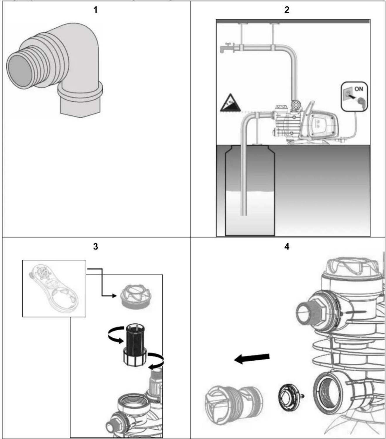
Fig - Fig. - Abb.- Fig.- Fig.- Phur.- Obr.- Fig.- Eik.- Joonis - Kuva - Sl. - abra - Fig. - att. - Afbeelding - Fig. - Rys.- Fig.- Fig. - Cxema - Obrazok - Sl. - Fig. - Sl. - Fig. - Resim - Man.
INDEX
1.APPLICATIONS 1
2. PUMPABLE LIQUIDS 2
3. TECHNICAL DATA AND LIMITATIONS OF USE 2
4. MANAGEMENT 2
4.1 Storage 2
4.2 Transport 2
4.3 Weight and dimensions 2
5.WARNINGS 3
6. INSTALLATION 3
7. ELECTRICAL CONNECTION 3
8. START-UP 3
9. ELECTRONIC CONTROL INTERFACE 4
9.1 Overview of the features 4
9.1.1 Description of the display: 4
9.2 Description of the functions 6
9.2.1 Pump ON/OFF (AUTO MODE, MANUAL MODE) 6
9.2.2 Priming phase 6
9.2.3 Alarms reset 6
9.2.4 Power ON/OFF indicator 6
9.2.5 Pump On/off indicator 6
9.2.6 Alarms indication 6
9.2.7 Dry running protection 7
9.2.8 ANTI-LEAKAGE 7
9.2.9 Max pump on 7
9.2.10 Pressure sensor alarm 7
9.3 First start up 7
9.3.1 Test on LEDs 7
9.3.2 First priming 7
9.4 Normal operations with CUT-OUT disabled (factory setting) 7
9.5 Normal operations with CUT-OUT enabled 7
-
PRECAUTIONS 7
-
MAINTENANCE AND CLEANING 7
11.1 Cleaning the suction filter 8
11.2 Cleaning the NRV 8
- TROUBLESHOOTING 8
13.GUARANTEE 9
WARNING


Read all this documentation carefully before installation:
Take out the plug before any intervention.
Absolutely avoid dry operations.
Protect the electropump against inclement weather.
The pump is equipped with a thermal overload safety device. In the event of any overheating of the motor, this device automatically switches off the pump. The cooling time is roughly 15 to 20 minutes, then the pump automatically comes on again. If the overload cutout is tripped, it essential to identify and deal with the cause of the overheating. See Troubleshooting.
1. APPLICATIONS
Self-priming centrifugal jet pumps with excellent suction capacity, even when gas is present in the water. Particularly indicated for water supply and pressure boosting in farmhouses. Suitable for small farming and gardening applications and for general hobby activity. Thanks to their compact and handy shape, they are also used for particular applications as portable pumps for emergency situations such as for drawing water from tanks or rivers.
In the case of a product with Wifi, consult the quick guide.
ENGLISH

These pumps cannot be used in swimming pools, ponds or basins where people are present, or for pumping hydrocarbons (petrol, diesel fuel, combustible oils, solvents, etc.) in accordance with the accident-prevention regulations in force. They should be cleaned before putting them away. See the chapter "Maintenance and Cleaning".
2. PUMPABLE LIQUIDS
Clean, free from solid bodies or abrasive substances, non-aggressive.
| Fresh water | ● |
| Rainwater (filtered) | ● |
| Clear waste water | ○ |
| Dirty water | ○ |
| Fountain water (filtered) | ● |
| River or lake water (filtered) | ● |
| Drinking water | ● |
- Suitable
Not suitable
3. TECHNICAL DATA AND LIMITATIONS OF USE
Supply voltage: 220-240V, see electrical data plate
- Delayed line fuses (220-240V version): indicative values (Ampere)
Storage temperature: -10^ + 40^
| Model | Line fuses 220-240V 50Hz |
| P1= 850 | 4 |
| P1= 1100 | 6 |
| P1= 640 | 4 |
| P1= 920 | 6 |
Table 3
| Model | P1=850 | P1=1100 | P1=640 | P1=920 | |
| Electrical data | P1 Rated absorbed power [W] | 850 | 1100 | 640 | 920 |
| P2 [W] | 600 | 750 | 380 | 560 | |
| Mains voltage [V] | 1~220-240 AC | ||||
| Mains frequency [Hz] | 50 | ||||
| Current [A] | 3.88 | 4.58 | 3.10 | 4.20 | |
| Capacitor [μF] | 12.5 | 16 | 16 | 12.5 | |
| Capacitor [Vc] | 450 | ||||
| Hydraulic data | Max. flow rate [l/h] | 3180 | 3750 | 3600 | 4800 |
| Max. head [m] | 43 | 45 | 32 | 40 | |
| Max. head [bar] | 4.3 | 4.5 | 3.2 | 4.0 | |
| Max. pressure [bar] | 6 | ||||
| Max suction depth [m/min] | 8m / <3min | 6m / < 3min | |||
| Range of use | Length of power cable [m] | 1.5 | |||
| Type of cable | H07 RNF | ||||
| Grade of motor protection | IPX4 | ||||
| Insulation class | F | ||||
| Liquid temperature range [°C] according to EN 60335-2-41 for domestic use | 0°C / +35°C | ||||
| Max. particle dimension [mm] | Clean water | ||||
| Max. ambient temperature [°C] | +40°C | ||||
| Weight | DNM GAS | 1" M | |||
| Net/Gross weight approx. [kg] | 9.6/11.8 | 10.3/12.5 | 10.1/12.1 | 10.9/12.9 | |

The pump cannot support the weight of the pipes, which must be supported in some other way.
4. MANAGEMENT
4.1 Storage
All the pumps must be stored in a dry covered place, with possible constant air humidity, free from vibrations and dust. They are supplied in their original pack in which they must remain until the time of installation.
4.2 Transport
Avoid subjecting the products to needless impacts and collisions.
4.3 Weight and dimensions
The adhesive plate on the packaging indicates the total weight of the pump and its dimensions.
ENGLISH
5. WARNINGS

The pumps must never be carried, lifted or allowed to operate suspended from the power cable; use the handle provided.
The pump must never be allowed to run when dry.
It is recommended to open/close the venting/drainage caps (2 and 6) without applying excessive force.
6. INSTALLATION
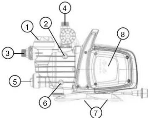
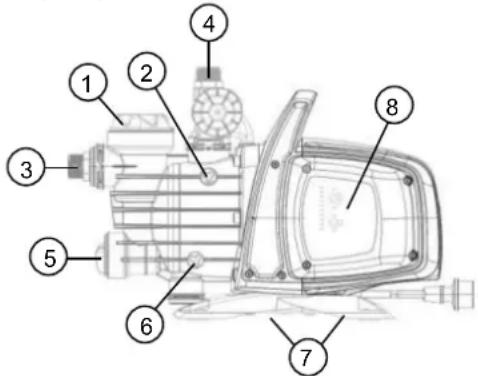
1 Pre-filter.
2 Vent cap.
3 Swivel suction connection.
4 Delivery connection.
5 Integrated non-return valve.
6 Drainage cap.
7 Vibration-damping rubber feet.
8 Electronic control interface.
The pump must be installed in a place protected from unfavourable weather conditions, and with an environment temperature not higher than 40^ .
The pump is provided with vibration-damping rubber feet, but in the case of fixed installations it is possible to remove them and provide anchorage to the base (7).
Do not allow the pipes to transmit excessive forces to the pump inlets (3) and (4), to avoid creating deformations or breakages.
It is always good practice to place the pump as close as possible to the liquid to be pumped. The pump must be installed only in horizontal position.
The pipes must never have an internal diameter smaller than that of the pump inlets; on intake, the pump is provided with a filter (1) and a non-return valve (NRV) (5).
For suction depths of over four metres or with long horizontal stretches it is advisable to use an intake hose with a diameter larger than that of the intake aperture of the pump. To prevent the formation of air pockets, the intake hose must slope slightly upwards towards the pump. Fig.2
If the suction pipe is made of rubber or flexible material, always check that it is of the reinforced vacuum-resistant type to avoid shrinkage due to suction.
In case of a fixed installation, it is recommended to fit a closing valve on both the suction side and the delivery side. This allows closure of the line upstream and/or downstream from the pump, useful for service and cleaning operations or for periods in which the pump is not in use.
The pump has a rotating inlet to facilitate installation (3) and (4)
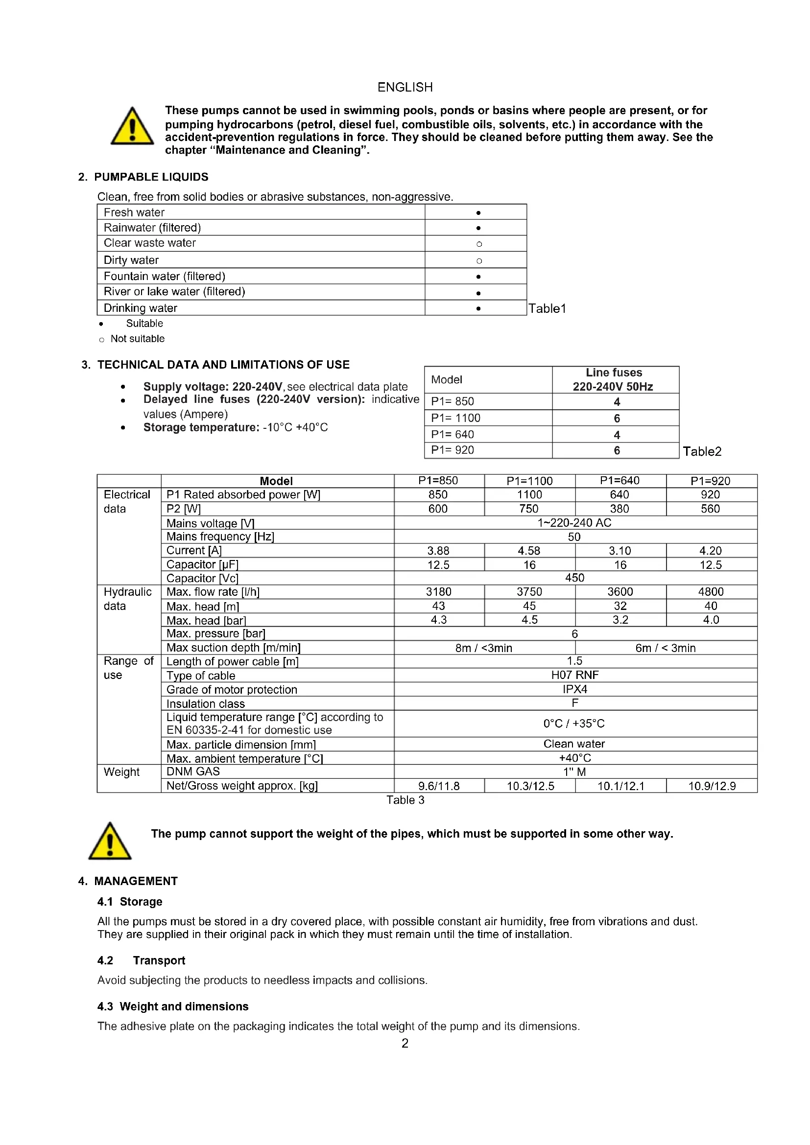
In the case of flexible pipes, if necessary, use a bend fig. 1 and the gardening kit composed of a PE pipe and a kit of couplings with lance. These are not supplied, but can be bought separately. In the case of very small dirt, as well as the integrated filter (1), it is recommended to use a pump inlet filter fitted on the suction pipe.
- Do not subject the motor to excessive starts/hour; it is strongly recommended not to exceed 20 starts/hour.

The diameter of the suction pipe must be greater than or the same as the diameter of the pump inlet, see Table 3.
7. ELECTRICAL CONNECTION

Ensure that the mains voltage is the same as the value shown on the motor plate and that there is the possibility of making a good earth connection. Follow the indications on the technical data plate and in this manual, table 3.
The length of the power cable on the pump limits the installation distance, if an extension is required, make sure that it is of the same type (e.g. H05 RN-F or H07 RN-F depending on the installation) see tab.
8. START-UP

Do not start the pump without having completely filled it with liquid, about 4 litres, until it comes out of the air vent cap (2).
If the water supply is finished, take the plug out of the socket immediately and switch off the pump. Avoid dry running.
ENGLISH
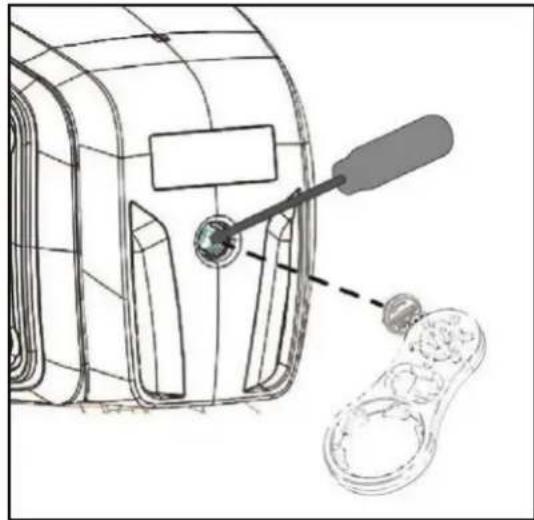
- Before starting, check that the pump is properly primed, filling it completely, with clean water, through the filling hole, after having removed the filling cap of the transparent filter (1), with your hands or with the appropriate tool provided. At the same time open the vent cap (2) to let out the air. This ensures that the mechanical seal is well lubricated and that the pump immediately starts to work regularly. Dry operation causes irreparable damage to the mechanical seal.
- The filling cap must be screwed on accurately until it stops (1), as must the vent cap (2).
- Insert the plug of the power cable in a 220-240V power socket. Attention! The pump motor will start immediately, the water will start to come out after a maximum time of 3 minutes, depending on the depth of the water level, in the well or cistern.
- The pump will continue to work and supply water. Attention! Avoid dry running.
- To switch off the pump, take the plug out of the power socket.

In case of problems with the priming, repeat the handling until all air in the suction is disappeared.
9. ELECTRONIC CONTROL INTERFACE
9.1 Overview of the features
| Description | Parameters |
| Controller board voltage, frequency | 1x220-240V, 50/60 Hz |
| Power on/off indicator | ● |
| Motor on/off indicator | ● |
| Alarms indicator | ● |
| Pressure indicator | ● |
| Mode indicator | ● |
| Auto Mode | ● |
| Manual Mode | ○ |
| Dry-running protection | ● |
| Anti-leakage | ○ |
| Max pump on protection | ○ (30 minutes) |
| Cut-in pressure | ○Variable (1.5 - 3.0bar) |
| Cut-out pressure | ○ (Cut-in + 1 bar) |
| Auto priming | ● |
| Selection buttons | ● |
= Fixed; = Selectable
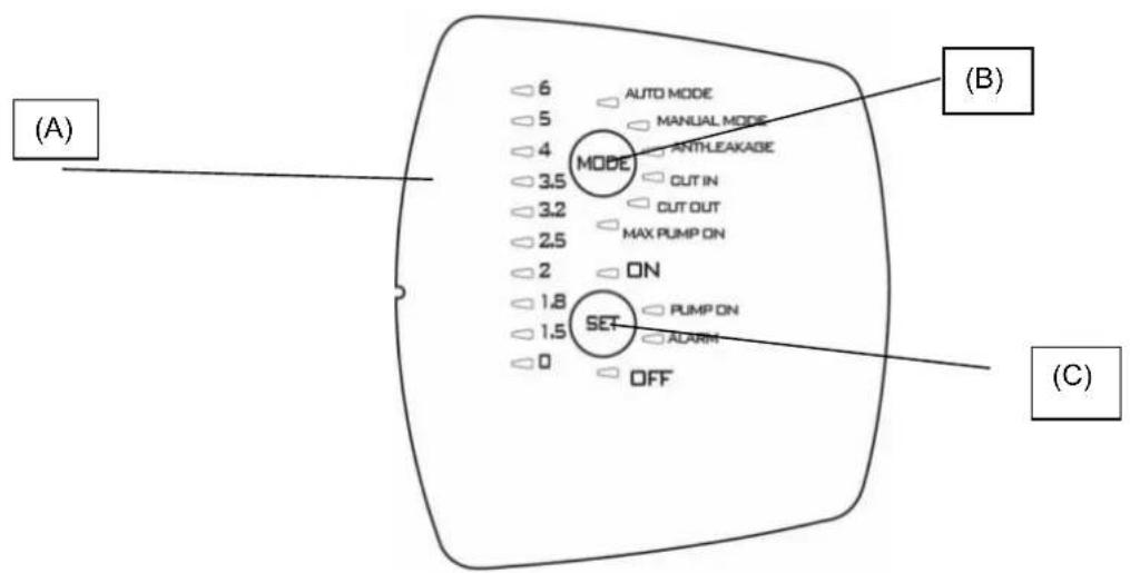
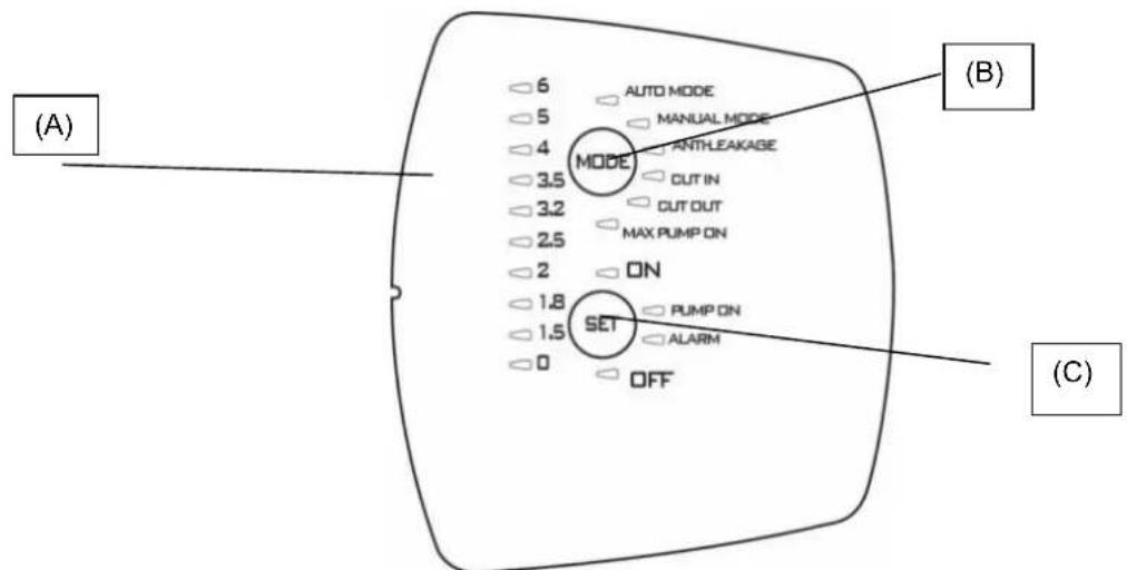
9.1.1 Description of the display:
(A) Pressure indicator LEDs
10 LEDs are used for indicating pressure from 0 to 6 bar. When the pressure in the system changes, the LEDs light up and switch off accordingly.
ENGLISH
| Function | Display configuration | Set | Alarm Reset |
| Auto Mode | AUTO MODE MANUAL MODE ANTHLEAKAGE CUT IN | ON: Enabled OFF: Disabled | |
| Manual mode | AUTO MODE MANUAL MODE ANTHLEAKAGE CUT IN | ON: Enabled OFF: Disabled | |
| Anti-leakage | AUTO MODE MANUAL MODE ANTHLEAKAGE CUT IN | ON: Enabled OFF: Disabled | Press SET |
| Cut in | AUTO MODE MANUAL MODE ANTHLEAKAGE CUT IN | Increase/Decrease | |
| Cut out | MODE ANTHLEAKAGE CUT IN CUT OUT MAX PUMP ON | Increase/Decrease OFF: disabled | |
| Max pump on | MODE ANTHLEAKAGE CUT IN CUT OUT MAX PUMP ON | ON: enabled OFF: disabled | Press SET |
(B) MODE selection button
Selectable modes:
1) AUTO MODE;
2) MANUAL_MODE;
3) ANTI LEAKAGE;
4) CUT IN:
5) CUT OUT,
6) MAX PUMP ON;
To unlock the choice of function press "MODE" button for 5 seconds.
Press "MODE" to scroll through the various operating modes (AUTO_MODE or MANUAL_MODE) or parameters to be modified (CUT IN and CUT OUT) or to enable certain functions (ANTI-LEAKAGE and MAX PUMP ON). While scrolling through the modes, the LED of the function selected will flash. On returning to AUTO_MODE the active functions will be highlighted by the relative LED lighting up with a steady light. See paragraph 2 (Description of the functions).
Indicators on "MODE"
AUTO MODE: the pump will work in automatic mode see 9.2.1
MANUAL MODE: the pump works in manual mode see 9.2.1, and the user can decide when to switch it on or off by acting on the "SET" button. SET-ON switched On SET-OFF switched Off.
CUT-IN: pressure setting (always enabled) minimum pressure below which the pump is activated, can be set between 1.5 and 3.0 bar, factory setting 1.8 bar; the pump is activated even if the flow is less than a minimum value of 1.5l / min , factory-setting.
CUT-OUT: pressure setting (disabled by default) above which the pump stops, the factory setting for "CUT-IN" + 1 bar (1 Led enlightened), but can be increased up to 3.5 bar (50.8 psi).
To enable it select the function by pressing "MODE" until the LED corresponding to CUT-OUT flashes then:
1) press SET for 10 seconds to unlock the function (now the led lights on the pressure values are switched on),
2) press SET to select the required value,
3) To disable the function, position the cut-out value on 0 [bar or psi].
4) exit the setting by pressing MODE.
ENGLISH
Note: the CUT-OUT value can be changed ONLY after having unlocked the function by pressing SET for 10 seconds long. After 1 second without pressing any button, the function will automatically lock again.
ANTI-LEAKAGE: protection against leakage. The function can be enabled or disabled: the factory setting is disabled. When enabled, if the condition is such that the pump is started up more than 6 times in 2 minutes, it will be stopped and the error will be indicated by means of the red LED flashing slowly on "ALARM".
To enable it select the function by pressing "MODE" until the LED flashes then press SET until the "ON" LED is switched on. To disable it press SET until the LED switches on to indicate OFF.
Once the cause is removed, reset the alarm, if still present, see 9.2.3.
MAX PUMP ON: maximum period of operation. The function can be enabled or disabled. The factory setting is disabled. When enabled, if the condition is such that the pump operates for more than 30 minutes, it will be stopped, no error indication is displayed.
This function is used to protect the installation if a valve is left accidentally open, in the event of breakage of a pipe, or in applications for irrigation.
To enable it, select the function by pressing "MODE" until the LED corresponding to the MAX PUMP ON function is switched on, then press SET until the "ON" LED comes on. To disable it, press SET until the LED switches on to indicate OFF.
(C) SET selection button
Selectable modes:
1) Reset Alarms;
2) Enable/disable in MODE (MAX_PUMP_ON, ANTILEACKAGE)
3) Increases parameters in MODE (CUT_IN; CUT_OUT);
4) Motor ON/OFF in MANUAL MODE;
5) Pump active/pump in standby in AUTO MODE
Press "SET" to modify the parameters; if the LED is switched to MODE-CUT IN or MODE-CUT OUT, the value will be shown on the pressure indication LED bar. On pressing "SET" the value will increase. After setting the required value, exit the modification by pressing "MODE" and restore the LED to MODE-AUTO and SET "ON" enabled.
Press SET also to enable/disable the Anti-leakage and Max pump On functions. After selecting the function using the "MODE" button, enable it by selecting SET-ON, to disable it select SET-OFF.
In "MANUAL" mode, the SET is used to switch the pump on or off, LED "On" or "OFF". In automatic mode AUTO-MODE it is used to turn it ON or in standby "OFF".
PUMP ON: indication that coincides with the motor running.
9.2 Description of the functions
9.2.1 Pump ON/OFF (AUTO MODE, MANUAL MODE)
Cut out disabled on inserting the plug after the test on the LEDs the pump switches on for 10 seconds.
Cut out enabled after the plug is inserted, the test is conducted on the LEDs for the first 3 sec (LED 0 indicates that the power is always On) and the "AUTO MODE" is set as default with the indicator "ON". The pump will start working if the pressure is less than the CUT-IN value and the flow is less than the minimum cut-in flow. The pump will continue to operate as long as the pressure remains less than the CUT-OUT value, and will switch off when this value is reached, independently of the flow.
While, if the "MANUAL MODE" is selected, by pressing once the "MODE", the pump will start up if the "ON" LED lights up, otherwise, if "SET" is pressed, the pump will switch itself off and the "OFF" LED will light up.
When the pump starts working, it will enter the PRIMING mode.
NOTE: Make sure the instructions for installation have been followed and that the pump is filled completely with water.
9.2.2 Priming phase
When the pump starts working, it will enter the priming mode, during this phase if there is no flow and pressure the motor will remain switched on for 3 minutes after which it will enter dry run alarm. But if flow and pressure are present during this phase, priming will be carried out and the pump will work normally.
9.2.3 Alarms reset
When there is an alarm, the red indicator on "ALARM" lights up. The alarm is reset by pressing "SET" once; if the cause of the alarm is eliminated, normal operation continues, otherwise the pump will return to alarm condition.
9.2.4 Power ON/OFF indicator
If power supply is present the pressure LED 0 on the LED bar lights up. If there is no power the LED remains switched off. Note: for long shutdowns it is advisable to disconnect the plug from the power supply.
9.2.5 Pump On/off indicator
When the motor is running, a "PUMP ON" blue light must be On to indicate this status. When the motor stops, this LED switches off.
9.2.6 Alarms indication
A steady red light or button on "ALARM" is activated when an alarm is present.
Dry-running: steady red light
Leakage: slow pulse
Max Pump ON (pump running for more than 30 minutes): 2 quick flashes separated by a longer pause.
Press "SET" button to reset the alarms.
ENGLISH
9.2.7 Dry running protection
If the pump is running dry, after a few seconds (40 sec.) it is stopped and an error indication appears with the steady red light on "ALARM".
After the initial 30 min when the pump is OFF a new restart attempt is made lasting 5 min. If this attempt is not successful, another attempt will be made every 30 min, up to a maximum of 48 times. If all these attempts fail, an attempt will be made every 24 hours.
The device automatically comes out of the Dry-running alarm status if the flow and/or pressure is restored. If the alarm is reset, see 9.2.3, a new attempt will be made after 40 sec.
Eliminate the causes and reset the alarm see 9.2.3.
9.2.8 ANTI-LEAKAGE
The function may be enabled or disabled. When enabled, if the condition is such that the pump is started up more than 6 times in 2 minutes, it will be stopped and the error will be indicated by means of the red LED flashing slowly on "ALARM". Eliminate the causes and reset the alarm see 9.2.3.
For the enabling procedure see Anti-leakage.
9.2.9 Max pump on
Maximum operating time. The function can be enabled or disabled. Factory setting is disabled. When enabled, if the condition is such that the pump works for more than 30 minutes, it will stop, and the ALARM light will flash.
This function is used to protect the installation if the valve is accidentally left open, in case of breakage of a pipe, or in applications for irrigation.
9.2.10 Pressure sensor alarm
The pressure sensor alarm of the device is activated if the pressure value is outside the operating range (0-15 bar). The pump is switched off, the error will be reset as soon as the pressure conditions return within the range.
9.3 First start up
9.3.1 Test on LEDs
When the device is started up the first time, or after the plug is inserted in the power socket, the Test is conducted on the 20 LEDs, for a few seconds during which all the LEDs will light up in sequence.
9.3.2 First priming
The pump will automatically be in AUTO mode set to ON.
There may be three possible behaviours:
1) Flow present but low pressure: exits the priming phase and starts normal operation.
2) Pressure present but no flow: after 10 sec. in this condition the pump will switch itself off.
3) No flow no pressure: the pump will switch itself off and the Dry-running error will be displayed after about 3. minutes, indicated by the red LED in SET-ALARM. Eliminate the cause and reset the alarm see 9.2.3.
9.4 Normal operations with CUT-OUT disabled (factory setting)
Cut-out disabled means the following behaviour is present:
The pump is activated if there is flow or pressure is absent, pressure is less than CUT IN (in 10 ms).
- The pump is stopped if the pressure is present but Flow is absent continuously for 10~s .
The CUT OUT LED will be switched off during normal operation. To modify the setting see 9.1.1.B.
9.5 Normal operations with CUT-OUT enabled
Cut-out enabled means the following behaviour is present:
- The pump is activated if the pressure is less than the CUT IN pressure.
- The pump is stopped if the pressure is higher than the CUT OUT pressure.
The CUT OUT will be switched on during normal operation. To modify the setting see 9.1.1.B.
10. PRECAUTIONS
RISK OF FROST: when the pump remains inactive at a temperature lower than 0^ , it is necessary to ensure that there is no water residue which could freeze, causing cracks in the plastic parts.
If the pump has been used with substances that tend to form a deposit, or with water containing chlorine, rinse it after use with a powerful jet of water in order to avoid the formation of deposits or encrustations which would reduce the characteristics of the pump.
11. MAINTENANCE AND CLEANING
In normal operation the pump does not require any type of maintenance. In any case, all repair and maintenance work must be carried out only after having disconnected the pump from the supply mains. When restarting the pump, ensure that it has been correctly reassembled, so as not to create a risk for persons and property.
ENGLISH
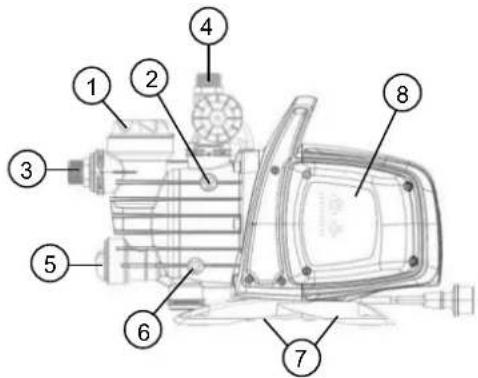
11.1 Cleaning the suction filter
Fig.3
- Switch off the electric power supply to the pump.
- Drain the pump, opening the drainage cap (6), after having first closed the gate valves upstream (if present).
- Unscrew the cover of the filter chamber, with your hands or with the appropriate tool provided.
- Extract the filter unit from the top.
- Rinse the cup under running water and clean the filter with a soft brush.
- Reassemble the filter, performing the operations in inverse order.
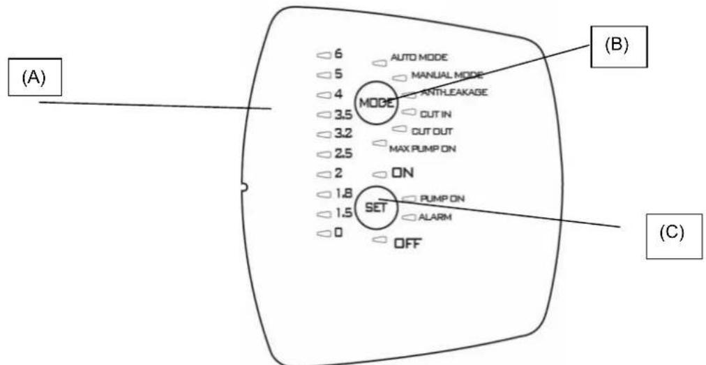
11.2 Cleaning the NRV
(Fig.4)
- Switch off the electric power supply to the pump.
- Remove the cap of the NRV (5) with the accessory provided.
- Remove the NRV check valve and clean it to remove any dirt fig.9.
- Assemble the parts, proceeding in inverse order to disassembly.
12. TROUBLESHOOTING

Before taking any troubleshooting action, disconnect the pump from the power supply (i.e. remove the plug from the socket). If there is any damage to the power cable or pump, any necessary repairs or replacements must be performed by the manufacturer or his authorized customer support service, or by an equally-qualified party, in order to prevent all risks.
| FAULT | CHECKS (possible cause) | REMEDY |
| 1. The motor does not start and makes no noise. | A. Check the electric connections.B. Check that the motor is live.C. Check the protection fuses.D. Possible intervention of thermal protection | C. If they are burnt-out, change them.D. Wait about 20 min until the motor cools Check and eliminate the cause.N.B.: If the fault is repeated immediately this means that the motor is short circuiting. |
| 1. The motor does not start but makes noise. | A. Ensure that the mains voltage is the same as the value on the plate.B. Look for possible blockages in the pump or motor.C. Check that the shaft is not blocked.D. Check the condition of the capacitor. | B. Remove the blockage C. Use the tool provided to release the shaft.D. Replace the capacitor |
| 3. The motor turns with difficulty. | A. Check the voltage which may be insufficient.B. Check whether any moving parts are scraping against fixed parts. | B. Eliminate the cause of the scraping. |
| 4. The pump does not deliver. | A. The pump has not been primed correctly.B. The diameter of the intake pipe is insufficient.C. NRV non-return valve or filter clogged. | A. Fill the pump with water and prime it, taking care to let air out by unscrewing the vent cap.B. Replace the pipe with one with a larger diameter.C. Clean the filter and, if this is not sufficient, the NRV. |
| 5. The pump does not prime. | A. Suction pipe is taking in air.B. The downward slope of the intake pipe favours the formation of air pockets. | A. Eliminate the phenomenon, checking that the connections and the suction pipe are airtight, and repeat the priming operation.B. Correct the inclination of the intake pipe. |
| 6. The pump supplies insufficient flow. | A. The suction pipe is clogged.B. The impeller is worn or blocked.C. The diameter of the intake pipe is insufficient. | A. Clean the suction pipe.B. Remove the obstructions or replace the worn parts.C. Replace the pipe with one with a larger diameter. |
| 7. The pump vibrates and operates noisily. | A. Check that the pump and the pipes are firmly anchored.B. There is cavitation in the pump, that is the demand for water is higher than it is able to pump.C. The pump is running above its plate characteristics. | A. Fix the loose parts more carefully.B. Reduce the intake height or check for load losses.C. It may be useful to limit the flow at delivery. |
ENGLISH
13. GUARANTEE

Any modification made without prior authorisation relieves the manufacturer of all responsibility. All the spare parts used in repairs must be authentic and all accessories must be authorised by the manufacturer in order to ensure maximum safety of the machines and of the systems in which they may be installed.
This product is covered by a legal guarantee (in the European Community for 24 months from date of purchase) against all defects that can be assigned to manufacturing faults or to the material used.
The product under guarantee may, at discretion, either be replaced with one in perfect working order or replaced free of charge if the following conditions are observed:
the product has been used correctly in compliance with the instructions and not attempt has been made to repair it by the buyer or by third parties.
the product has been consigned to the outlet where it was purchased, attaching a document as proof of purchase (invoice or cash register receipt) and a brief description of the problem found.
The impeller and parts subject to wear are not covered by the guarantee. Intervention under guarantee does not extend the initial guarantee period in any way.
ITALIANO
INDICE
- APPLICATIONI 10
- LIQUIDI POMPABILI 11
- DATI TECHNICIE LIMITAZIONI D'USO 11
- GESTIONE 11
(C) Bouton de selection SET
9.2.5 Indication pompe On/off
| Función | Configuración Pantalla | Set | Reajuste Alarma |
| Auto Mode | AUTO MODE MANUAL MODE ANTHLEAKAGE CUT IN | ON: habilido OFF: inhabitido | |
| Manual mode | AUTO MODE MANUAL MODE ANTHLEAKAGE CUT IN | ON: habilido OFF: inhabitido | |
| Anti-leakage | AUTO MODE MANUAL MODE ANTHLEAKAGE CUT IN | ON: habilido OFF: inhabitido | Pulse SET |
| Cut in | AUTO MODE MANUAL MODE ANTHLEAKAGE CUT IN | Aumenta/Disminuya | |
| Cut out | MODE ANTHLEAKAGE CUT IN CUT OUT MAX PUMP ON | Aumenta/Disminuya OFF: inhabitido | |
| Max pump on | MODE ANTHLEAKAGE CUT IN CUT OUT MAX PUMP ON | ON: habilido OFF: inhabitido | Pulse SET |
3. TEXHNUECKN DAHHN IN OPGAHUHEHNA 3A YIOTPEBA
3axpaHbauo HanpeKeHne :220-240V,BnK ndeHT. Ta6eNa C eNEKTpUyeCKnTe DaHHN.
- PpeIpa3nteHn no IHHraTc OTIOxHo NO DeIcTBne (Bepcn 220-240V): npImepHn cToHocTn (Ampepn).
TemnepaupaHacklaJaHpaHe: -10^ + 40^
Tabnua 2
| Mодeн | Пре徳паЗитей по Линьта 220-240V 50Hz |
| P1=850 | 4 |
| P1=1100 | 6 |
| P1=640 | 4 |
| P1=920 | 6 |
Ta6nua 3
| Моden | P1=850 | P1=1100 | P1=640 | P1=920 | |
| Данни -"/"/"/"/"/"/"/"/"/"/"/"/"/"/"/"/"/"/"/"/"/"/"/"/"/"/"/"/"/"/"/"/"/"/"/"/"/"/"/"/"/"/"/"/"/"/"/"/"/"/"/"/"/"/"/"/"/"/"/"/"/"/"/"/"/"/"/"/"/"/"/"/"/"/"/"/"/"/"/"/"/"/"/"/"/"/"/"/"/"/"/"/"/"/"/"/"/"/"/"/"); | Р1 Нominational KOHcymipara Moiuct [W] | 850 | 1100 | 640 | 920 |
| P2 [W] | 600 | 750 | 380 | 560 | |
| Мөжово нарөжени [V] | 1~220-240 AC | ||||
| Мөжова чECTOTA [Hz] | 50 | ||||
| Тok [A] | 3.88 | 4.58 | 3.10 | 4.20 | |
| Кондэнзатор [μF] | 12.5 | 16 | 16 | 12.5 | |
| Кондэнзатор [Vc] | 450 | ||||
| Данни -"/"/"/"/"/"/"/"/"/"/"/"/"/"/"/"/"/"/"/"/"/"/"/"/"/"/"/"/"/"/"/"/"/"/"/"/"/"/"/"/"/"/"/"/"/"/"/"/"/"/"/"/"/"/"/"/"/"/"/"/"/"/"/"/"/"/"/"/"/"/"/"/"/"/"/"/"/"/"/"/"/"/"/"/"/"/"/"/"/"/"/"); | Мамс. Дебит [I/h] | 3180 | 3750 | 3600 | 4800 |
| Мамс. наор [m] | 43 | 45 | 32 | 40 | |
| Мамс. наор [bar] | 4.3 | 4.5 | 3.2 | 4.0 | |
| Мамс. налгагане [bar] | 6 | ||||
| Мамс. Дьлбочина на засмү KBане [m/min] | 8m / <3min | 6m / < 3min | |||
| Сфера на"/"/"/"/"/"/"/"/"/"/"/"/"/"/"/"/"/"/"/"/"/"); | Дылж. Зхралвац кавел [m] | 1.5 | |||
| Вид кавел | H07 RNF | ||||
| Стени на зашита на двигателя | IP X4 | ||||
| Клас История | F | ||||
| Температерен обхBAT на туностра ["℃"] | 0 °C / +35 °C | ||||
| Сыласно EN 60335-2-41 3a/botoba уnotpeba | |||||
| Мамс. размер на чASTИцITE | ЧИСТА ВОДA | ||||
| Мамс. Temпература на okолнatable среда ["℃"] | +40 °C | ||||
| Тergио | DNM GAS | 1" M | |||
| Тergио Heyo/Бруто прибл. [kg] | 9.6/11.8 | 10.3/12.5 | 10.1/12.1 | 10.9/12.9 | |

Iomnata He Moke da n3dbpxk TeXeCTTa Ha Tpb6nte, KOrTO B IpOtnBEN cIyuaT Pra6Ba da ce NoHece.
4. CTONAHNCBAHE
4.1 CbxaheHne
Bcunn nomnn trpa6ba da ce cbxpanraat B 3akpnto, cyxo macto, no Bb3MOXHOCT C NOCTOHNHBA NaxHOCT Ha Bb3dyxa, Be3 Bv6paunu npax. DocTabrT ce B opunHaONAKOBKa, B KOrTO Tpa6ba Da OCTaHaT DO MOMeHTa HA MOHTaKa.
4.2 TpaHcnpot
1368aBaeTda noDnaraTe npOdykTte Ha HeHyxHn yApn n cblcbu.
БылгAPСКИ
4.3 Terno pa3mepn
IeHTnKauoHHnT CTKepe, noCTaBeH Bbpxy onakOBkata, cbDbpxa yka3aHne 3a o6to Tero Ha eJektpueckata nomna n 3a HeHnTe pa3mepn.
5. NPEyNPEKKeHnA

Iomnnte Hnkora He Tpr6Ba da ce TpaHcnoptnpaT, NOBnurat NIn Nyckat B DeiCTBne, Okayehn 3 3axpanBaunKa6en, n3non3BaTe cneunaHaHaTa dpbXka.
- Tomnata Hikora He Tp86Ba da ce octabra da pa60Tu Ha cyxo.
Ipenopbya ce da OTbaprTe/3aTbaprTe n3nyckatHnTe n dpehaxnTe TaHa nomnata (2 n 6) 6e3 da n3non3BaTe npekomephna cuna.
6. MOHTIPPAHE
1IpeBapnteHΦnJtbp.
2 N3nyckateJIHa Tana.
3OpneHTnpyema BcMykaTeJHa Bpb3ka.
4 HanopHa Bpb3ka.
5 INTerpupaH HeBb3BpaTeH KJIanaH.
6 Tana 3a n3ToBaHe.
7IymeHnKpaetaCpeuByBn6paun.
8 EneKtpoHEn HHTeppeic 3a ynpabJeHne.
EneKtpueckata nomna Tp6Ba da ce nHctanipa Ha MrcTo, 3aunTeHO OT He6narOpnraTHn aTMocpepn yCIOBnI TEMpepaTpa Ha OKoHNHATA CpeDa, He No-BnCOKa OT 40^
Iomnatae cnahea c kpaeta Cpeu y Bnbaun, Ho B cnuya H a KncpauH MoTaxn E B3MOxHO da n npemaxhe T da npedBnnte ankepno 3axBaana He Ha HOceua OCHOBA (7).
I36raBte Tp6bTe da npedaBt 3BbHpeHN yCNnRA bM OTbOpNTe Ha nomnata (3) n (4), 3a da He ce cb3daBAt deopmaun nn CuynBAHn.
Bnharne no-dobpe nomnata da ce moHTnpa 6n3o do 3axpaHbaHeTo c B0da.
Ja ce MOHTnpa cAmO B XOpN3oHTaJIHO NIOJIOKeHne.
Tp6bTe He Tp8Ba HkOra Da NMAT BbTpeWeH dAmetBp, NO-MaTbK OT TO3n Ha OTbOpTe Ha eNekTpueckata NOMna nPipn BCMyKaTeHATA Tp6a NOMnatae cHa6deHa C cΦnTbp (1) NHeBb3BpaTeH KNaH (HBK) (5).
Pn3acmykBaHe O T bIbOuHn Hno-roJMa 0T 4 M. nIy dIbIg XOpIHOaHE yAcTBK, ce npenopbYBa DOnbHInTeHOMHTnpaHe Ha MaIbK yAcTBK C DNAmetbp NO-roJAM OT To3n HA BXoJa HA NOMnTa. 3a N36paRbHe Bb3MOxHocTTa 3aOBpa3yBaHe Ha BBcDyUHN MExypn B TpKaTa, HAKIOHa JNeKo Da CE CHINXABA KbM NOMnTa.Φur.2
Ako BCMykaTeHaTa Tp6a e rmyeHa nIOT dpyr TbBkab MaTePnA, BnHar npOBepBaTc daIc aO TNDnEn Tn, yCTOnuHbBAkyM, 3a Da ce N36eHaT CTecHeHn Iopadn BCMykaTeHHra epeKT.
B cnuya H a qncnpan MoNTax Ce npenopbya Da MOHTupate 3aTBapra Knaan KaKTO OT cTpaHata Ha BCMyKbaHe, Taka nOT cTpaHata Ha HarHeTaTeJIHATA Tpb6a. ToBa No3BOJRA Ba ce 3aTBOPN INHmra TpeDn Nnn CneI NOMnA, KOeTo e yDo6Ho 3a BCNUKN Oepauu N NOODPbXkna N NOUcHCTBaHe Nn 3a nepNOu, B KOnTO NOMnAte He CE n3NON3Ba.
Iomnatae cnaea C Bbpta C BxO,3a da ce ynech MoTaxa. (3) n (4)
Pn Mapkyu, aKc Ce Hana, n3non3BaIte KOnJHO qI.1 n rpaHapckn KOMJIeK, cBCToUc ce ot PE Tpb6a n KOMJIeKt C MyfC hAkapaiHnk, KOTo He ca DoCTaBeHN, HO MORaT Da CE DoCTaBRT OTDeHNO.
Pn HAnuHTo Ha 3aMbpcBaHnna C MHO rMaIKn pa3Mepn Ce npenopbYba Da n3no3BaTe,OCBeH Brpaednna qntbp (1), pHTbp Ha BXOda Ha NOMnata, MOHTnpaHa BCMykATEHnata Tpb6a.
He noDnaraTe DnraTeHa npeKaJeHO MHoro CTapTnpaHryac, CInHO ce npenOpbYBa da He ce npebuabat 20 CTapTnpaHry/ac.

DnAmEtbpbT Ha BcMyKaTeHnHaTa Tpb6a Tpr6Ba Da 6bDe no-roJMa nn paBeH Ha DnAmEtbpHa OTBopa Ha eneKtpnueckata nomna, BnK TaBnua 3.
7. ENEKTPNUECKO CBbP3BAHE

a ce npOBepn dann 3axpaHbauoTo HAnpeXeHne OTROBapn Ha n3NCKBaHTo Ha nomnata n da ce oue Bb3MOxHOCTTa 3a HaJeKdHa 3a3EmKa PnpIbPkaTe ce KbM yKa3aHnra, nocOeyn B Ta6enata C TEXHuecknte daHHn N TOBa pBkoBOcTBo, Ta6nua 3.
IbJxHaTa Ha 3axpaHbuaa Ka6e, HAnuye c nomnata, orpaHuyBa pa3cToHHeTo 3a MoHTaK, aKO ce Hana r nnon3BaHe Ha yBbXHTen, yBepete ce, ye e ot cbunr Tn (hanp.H05 RN-F nn H07 RN-F B 3aBucmOCT OT MOHTaKa) Bux Ta6n.3.
ББЛГAPСКИ
8. CTAPTINPAHE

He cTApTpaIte nomnata 6e3 da cTe r HanbHnn HAnbHc TceHocT,OKoN O 4 nITpa,doKATO 3aOnHe da n3n3a npes tanata 3a oCbo6oxdaBaHe Ha Bb3dyx (2).
B cnuyaHa n3yepnbaHe Ha BOdHnpecypc, He3a6abHo n3KnHouTe uenceJa, C KoEt O cnpaTe nomnta. N36raBte paobotaHa cyxo.
- Ipei NyckaheTo Ha NOMnata npOBepe TaJIH NOMnTa e npaBnHO 3aJrTa, KATO pncTbNITE KbM cIIOCTHO To HANbJIbAHe C NCTa BODa Ppe3 CNEuHaHnO TBOP, CNeI KATO CTe OTCTpaHnI Tanata 3a 3apeXdaHe Ha npo3paHnI PhNTbp (1) pbUHO INC bC CNEuHaHnI INCTpyMeHT, DOCtABeH C MaunHata. EINHOPEMeHHO C TOBa OTBopTe N3NyckatEnHata Tana (2), 3a Da OCBO6OnTE Bb3dyxa. TOBa O3HaUba, Ye MexAHyHOTO yNtBTHHeE e Do6pe CMA3aHO n NOMnTa 3aNoCb BaEDHa R HopMaJIHATA cn pa6ota. Pa6ota B cyx peKIM BoDn DO HeONpabHmna NobpeHa Ha MexAHnuHOTO yNtBTHHeHne.
- Cnej TOBa TanaTa 3a 3apeXdaHe ue Tp6Ba Da ce 3aBHe BnMaTeHNO Do cnpaHTo (1), KaKTo n HnyckaTeJHaTata Tana (2).
- BkHouTe UeCenHa 3axpaHbuaKabEn KbM 3axpaHbua KOHTaTcT O220-240V. BnMaHne! DnurTaTeIaH NOMnata uce Ce CTaptnapa He3a6abHo, BOdata uze 3anOHe da N3JIn3a CneI MAKCMym 3 MNHyTN, Koeto 3aBNCN OT Dbl6OuHATA Ha HNBOTo HA BOdA T B KnaDeHeca ININ B cIcCTepHata.
- Nomnata 7e npoDbJnx da fynKuHnHpa n da cepnn Boda. BHIMaHne! PpeDToBpTaTbAaTe pa6oTaT a Ha cyxo.
- 3a da cnpete Nomnata, n3knouyete uencena Ha 3axpaHbaunKa6eJ.

B cnuyaH na npo6nemn c63 3aJInBaHeTo npedn npcKaHe B deNCTBne, nobTOpe To n3ue3He BCNUKnT Bb3dyx npn BCMyKBAHeTO.
9. ENEKTPOHEH INHTEPΦEIC 3A YIPTABLHeH
9.1 O63op Ha xapaKTepeNCTNKKeT
| Описанne | Параметри |
| Нарөжөнөе, чектоа на платкata | 1x220-240V, 50/60 Hz |
| Инданы сponь off 3a нарөжөнөе | ● |
| Инданы сponь off 3a двига teуя | ● |
| Инданы Аларми | ● |
| Инданы Налагао | ● |
| Инданы Рожим | ● |
| Auto Mode | ● |
| Manual Mode | ○ |
| Зашота срочу сух стапт | ● |
| Зашота срочу тechове | ○ |
| Зашота Мax pump on | ○ (30 минут) |
| Налаягане Cut-in | Опоменл BO (1,5-3,0 bar) |
| Налаягане Cut-out | ○ (Cut-in + 1 bar) |
| АВТOMATУно 3аливанe | ● |
| Бутои 3a сelenеця | ● |
- =Фнкиран;O=ИзбираeM
ББЛГAPСКИ
9.1.1 OncaHne Ha dncnpe:
(A) CBeToDnOHN HnDnKaTOpN 3a HaJIraHe
I3noJ3BaT ce 10 CBeToDnOda KaTO INnKaUma 3a HAnraHTo OT O do 6 bar. Korato HAnraHTo B CnCTeMaTa ce npomeHa, CBetoNDnte CBeBAT NnN n3rCaBt NocJeDoBaTeNo.
| Фунreichа | Конфicientsразец на дисп肺炎 | Set | Reset Alarm |
| Auto Mode | AUTO MODE MANUAL MODE ANTHLEAKAGE CUT IN | ON: Актычиран OFF: Deakтычиран | |
| Manual mode | AUTO MODE MANUAL MODE ANTHLEAKAGE CUT IN | ON: Актычиран OFF: Deakтычиран | |
| Anti-leakage | AUTO MODE MANUAL MODE ANTHLEAKAGE CUT IN | ON: Актычиран OFF: Deakтычиран | НатOMICе SET |
| Cut in | AUTO MODE MANUAL MODE ANTHLEAKAGE CUT IN | Увелич/Намал | |
| Cut out | MODE ANTHLEAKAGE CUT IN CUT OUT MAX PUMP ON | Увелич/Намал OFF: Deakтычиран | |
| Max pump on | MODE ANTHLEAKAGE CUT IN CUT OUT MAX PUMP ON | ON: akтычиран OFF: Deakтычиран | НатOMICе SET |
(B) Bytoh 3a n36op MODE
I3bpaempekmn:
1) AUTO_MODE;
2) MANUAL MODE;
3) ANTI LEACKAGE;
4) CUT IN;
5) CUT OUT,
6) MAXPUMP ON
3aJe6nokpaHe Ha n36opa Ha yHKunra Ta B“MODE”/PEKIMI,HaTncHe 6yToHa“MODE”B npoJbJxHne Ha 5 ceKyTm.
HaTnCHete "MODE", 3a da npEnCTte pa3nHHTe pa6oTHpeKIMN (AUTO_MODE nnnMANUAL_MODE) nnnpametpn 3a npomraHa (CUT IN n CUT OUT), nIn 3a da aktubipate HkON yHKcun (ANTI-LEAKAGE m MAX PUMP ON). NpBpeMe Ha npEnCTbaHTo CBeToNDIObT 3a n36paHata yHKcUNIe npemrBa. BeDhJck cneI kato ce BbpHete BpeKIM AUTO_MODE, aKTHBHNTe FyHKcUNIe Ce otUeTa Tcbc cbOTBeTHna NOctOHHo CBeTeu CBeToIDNo. BnK naparpa2 (Onncahne Ha FyHKcUNTE).
HdkKaTOpn 3a“MODE"
AUTO MODE: NOMnata ue pa60TN B aBTOMaTHueH peXHM, BIX 9.2.1
MANUAL MODE: NOMnata paobTu B pbyeH peXIM, BIX 9.2.1, noTpeBnteIaT peXaBA KOra Da a BKIOUH N I3KIOUH, KaTO n3no3Ba byoHa "SET". SET-ON BkIOUeH SET-OFF n3KIOUeH.
ББЛГAPСКИ
CUT-IN: HactpoBaHe Ha HalaReHe (BnHaHn AKTbnpaHo), MmHmAlHo HalaReHe nOd TOBa, C KoETo ce akTbnpa, MoKe Da ce HactpoMekdy 1.5 n 3.0 bar, fapuH No 1.8 bar; nomNaTa ce akTbnpa, dOpn Ako nOTokbTe nOd MmHmAlHa cToHoc 1.5 l/min, HactpoHa e fapuHNo.
CUT-OUT: HactpoBae Ha HnIraHe (deaktnbpuH) pressione sopra la quale la pompa si arresta, di fabbrica impostato a "CUT-IN" + 1 LED HnIraHe NaTobA, npN KoETo nomnata cnnpa, fapbnuHo e HactpoeHo Ha "CUT-IN" + 1 bar, Ho MoKe da ce yBeJIuHabAo 3.5 bar (50.8 psi).
3a da aKTHBnape, n36peTe yHKnraTa, kato haTnchete "MODE",doKaTo cbOTBeTHnT CBeToDnOd 3anOHe da npemrBa, cneI KOeTO:
1) HATNCHE T SET 3a 10 cekyHn, 3a OTKIOUVAHTo Ha yHKuYrTa (TOraba ue ce BKnOvat LED nHdkaTopnte Bbpxy CTOHOCTNE 3a HAnraHTo),
2) HATNCHETe SET, 3a da n36peTe JeIaNHaTc CTOnHOCT,
3) 3a DeakTbnpaHTo Ha cyHKuYra, 3adaTe cToHocCTTa 3a nKlIOvBaHe cut-out Ha O [bar nn psi],
4) n3JIe3Te OT HAcTpOJaTa, KaTo HaTInChTe MODE.
3A5EJIEXKKA: cmoHocmma 3a u3KnOueBaHe CUT-OUT moKe da bde npomeHa CAMO cned omKnIOueHa H a fyHKUma, hamuckau bymoHa SET 3a 10 cekyHou. Cned 1 cekyHda, be3 da hamuckame Koimo u da e bymo, fynkuMa ue ce 6nokupa omHOBO.
ANTI-LEAKAGE: 3aunTa Cpeu Ty TceOBe. FyHKnraTMOKe Da ce aKTNbnpa nn DeakTNBnpa. FabpnuHO e daekTNBnpaHa. Korato e akTNbnpaHa, ako e yctaHOBeHo ycNoBneTo nomnata da ce cTaptnpa nobuee ot 6 nTn 3a 2 MNHTn, Ta ue cnpe nIe Ce OTBeNk rpeWka Ype3 6abH0 npemrBaau YepBEN CBetOnoD 3a "ALARM".
3a da raakTNbupate, n36epete cyHKunra, kaTo hATnchete "MODE", dokaTo cbOTBeTHnT CBETOno3anOHe da npemrBa, cneK KOeTO hATnCHete SET,dokaTo CBETOnoDbT ON"CBETHe. 3a da deakTNbupate, hATnCHete SET,dokaTo BKIOueHaTa CBETnHa NOKaKe OFF.
Bedhck cnei kato npuHnHa e otctpaHe, HynpaIte anapMaT, aKO BCE oSe e HAnuHa, BIX 9.2.3.
MAX PUMP ON: MaKcImaHepnOHa yHKUHOHPaHe. FyHKUraTa MoKe da Ce aKTbnpa NnN deakTbnpa. FapuHo e DeakTbnpaHa. Korato e aKTNbpaHa, ako e ycTaHOBeHO ycNoBneTo nomnata da pa60Tu 3a nobee ot 30 MHyTu, Ta ue cnpe, HMa da ce noBv HkKaBA uHdkauza 3a rpeka.
Ta3nФyHKiMaCe H3noL3Ba 3a 3aunTa Ha HnCTaJaCnraTb CnyuHa Na CnyuHaHO OCTaBHe Ha OTbOpEn KpaH, B CnyuHa KaBCBaHe Ha Tpb6a Hnnpn H3noL3BaHe 3a HnOBAhe.
3a da aakTNBnpat, n36pepe yHKunra, kaTo haTnchete "MODE", doKato cboTBetHnrt CBtoDnO 3a MAX PUMP ON octane BkIouen Cnei Koeto haTnchete SET,doKato cbTeoOnobT "ON"CBtHe.3a da deakTNbupate, hatachete SET, doKato BkNooheHa cBeTInHa nokake OFF.
(C) Bytoh 3a n36op SET
N36paempejIMM:
1) Pecet anapm.
2) AkTbBupa/DeakTbBupa B MODE (MAX_PUMP_ON, ANTILEACKAGE).
3) Ybelenuaba napameTpne B MODE (CUT IN; CUT_OUT).
4)Диагген ON/OFF B MANUAL MODE.
5) AkTnBHa NOMna/NOmNa B pexKIM Ha rTOBHOCT B AUTO MODE.
HaTnchTe "SET", 3a Da npomEnHe npametpnte, B cnuyaHc CBeToDnObT 3a MODE-CUT IN nIN MODE-CUT OUT CBETN, CTOnHOCTTa 1e Ce NOKaKe Ha CBeToDnOHaTaNHTA 3a NOKa3BaHe Ha HAnraHcTo. C HATnCKaHcTo Ha "SET" CTOnHOCTTa 1e Ce yBENuN. CNeI KaTO cTe HAcTPOUIN XeNaHATA CToHOCt, N3Ne3Te OT IpOMHaTc C HATnCKaHcHa "MODE" n HAcTPOBaHe Ha CBeToDnOda Ha MODE-AUTO n AkTnBupaHe Ha SET "ON".
HaTnCHeTe SET cbso n 3a da akTNBpuate/deakTNBpuate yHKuHne Anti-leakage n Max pump On. Cnei kato cTe n36paJn fynKcunTa c 6byToHa "MODE", akTNBpuaiTe j, kato n36epeTe SET-ON, 3a da a deakTNBpuate, n36epeTe SETOFF.
B pexm "MANUAL"6yToHbT SET ige cIyKn 3a BkIOUbaHe IIN N3KIOUbaHe Ha nomnata, CBeTei CBeToIOoHa "On" IIN Ha "OFF".
B aTOMaTHueH peXIM AUTO-MODE ue nocIyKs 3a akTbIbpaHe "ON" IIN BIn3aHe B peXIM Ha roTOBHOCT "OFF".
PUMP ON: INHINKAUN, KOATO CbOTBcTCTBa HA yHKUOHpaU DBIRATEJ.
9.2 Onncahne Ha yHKunTe
9.2.1 Nometa ON/OFF (AUTO MODE, MANUAL MODE)
Deaktnbpancut out npn BkIIOUbaHeTo Ha uenCeHa Cnei TeCTBaHe Ha CBeTOIOIDTe NOMnTa ce BKIOUBA 3a 10 CEkyHn.
AKTNBipancut out CneI KaTo 6eN BkHueH,3BbPseHo e TcTeBaHeTo Ha CBeTOnIOJnte 3a NpBHTe 3 CEkyHn (BKIOUBAHeTo HA CBeTOINoD 0 NOKA3BA BNHaHn HAnuYe Ha HApEKeHne) n Ce HAcTpOBa No NOpa36npaHepKIM "AUTO MODE" c BKIOUBAHe Ha INdkaTopHaTa JAmNa "ON". POMnata ige 3anoHne da paOtn, aKO HAraHeTo e noCTOHocTTa CUT -IN, a noToKbT e noD MINHMannnnotok 3a cut-in. POMnata ige npOdbJnx da paOtoNdoKaTo HAnraHeTo e noCTOHocTTa CUT-OUT, npn doCTnRaHeTo n ce n3KnOHy He3ABNCmO OT notoka.
Ako obaue 6bIe n36paH peKMM "MANUAL MODE", c eHOKpaTHOto HaTnCKaHe Ha 6yToHa "MODE", NOMnTa Ie ce CTapTnpa, aKO CBeTOAnIOBbT "ON" CBeTN, B npOTnBEH Cnyuay C HATnCKaHETo Ha "SET", NOMnTa Ie ce N3KnUOnn Ie CBETHe CBETOnIOBbT "OFF".
Korato nomnata 3anouhe da pa6oTn ue Bne3e Bpekm 3AJIBAHE.
3a6eJekka: YBepeTe ce, ye cTe CnEBAJIH INCTpyKUInTe 3a INHCTaJIInpAHe N Ye NOMnata e 6NJHa HAnbJIHO nOToneHa BbB BOda.
ББЛГAPСКИ
9.2.2 Φa3a Ha 3aJIbBaHe
Korato nomnata 3anoyhe da pa6oTn, 1e Bne3e B pexmHa 3aJInBaHe, NO BpeMe Ha Ta3n P3a3a, aKO He ce yctahOBn nOTOK HAnraHe, 1e noDlbpka pa6oTaTn Ha DniratEnb IpoDbJIkeHne Ha 3 MInHyTn, CNeI KOeTo 1e BJe3e B peXMM Ha anapMa 3a pa6oTa Ha cyxo. Ako B To3n BpeMeBn INTePbaN Ce OTYe TnOcTK Nn HAnraHe, 1e 6bJe N3BbpSeHo 3aJInBaHe n NOMnata 1e pa6oTn HopMaJIHO.
9.2.3 Pecet anapm
Korato e haIue anapma, ue CBethe YepBEN CBeTINHEn INHdkatop "ALARM". Pecet Ha anapmata cTaba c eHOKpaTHo HATNCKaHe Ha 6yToHa SET", aKO npuHATA, KOaTO ro e npeIN3BnKaJa, e 6nJa OTCTpaHeHa, ue npoDbJnx C HopMaHOpHKUHOHPaHe, B npOTIBeCNyauh NOMnTa Ue BJIe3e B abApneH pexm.
9.2.4 INHdkaun on/off 3a HanpexeHne
Ako mHa HanpejEHNe CBToNDbT 3a HnraHe O Ha CBToNDHata WnHa 1e CBTe. Ako Hma HanpejEHe, To3n CBeTOIOI HMA Da CBTe. 3aBJIeKka: 3a IbIgN nepoHn Ha HeAKTNBHOCT, ce npenOpbYBa da cnpTe HanpejEHeMeTO, KAto N3BaDITe Uencena.
9.2.5 INHdkauon/off 3a nomnata
Korato Dnurateta paobTu, cnHra CBeTnHa Ha "PUMP ON" Tpr6Ba da CBETu, 3a da ce O3Nau yHKUHOHPaHETo. Korato Dnurateta cnpe, To3n CBeTOIOu Ie n3rache.
9.2.6 INHdkaun3a aJapMnTe
IocToHHa Hn npemrBaHa cepBHea CBETnHa 3a "ALARM" ce aKTHbupa, KOraTO nMa aIapMa.
Pa60Ta Ha cyxo (Dry-running): noctoHHa YepBeHa CBETnHa.
Teu (Leakage): 6aBHO npemrBaHe.
Max Tomna ON (nomnata fynkunohnpa 3a nooe ot 30 mnytn): 26bp3n npemrBaHn eHa no-dbIra nay3a.
HaTnCHTe"SET",3a da hyInpate aIapMnTe.
9.2.7 3aunita cpeu cyx ctap (Dry running protection)
Ako nomnata paobTu Ha cyxo, cnei HraKoIco cekyHdn (40 cek.) cnpa n ce noBra Hndkaun 3a rpeWka C nocToHHa cepBa CBtTnHa 3a "ALARM".
CneI npboHauaneH nepnoD ot 30 mN, npe3 KOJTo nomnata e B cbctOAHNE OFF ce npabn HOB onnt 3a cTAPtnpa 3a CpOK OT 5 MN. Ako I TO3n ONIT e HeycneWeH, ue Ce HApBn Dpyr Ha BCEkn 30 MN.,do MaKcmym 48 nbTN. AKO Te3n ONIT ca HeycneuH, ue ce npabn EHN Ha BCEkn 24 Yaca.
YcTPOINCTBOTO ABTOMATUHO H3N3a OT aIapMaTa 3a cyx XOD, aKO hMa IOTOK N/INHajraHaHe.
Ako ce Hapabn peceT ha anapMaTa, BIX 9.2.3, ue ce Hapabn HOB ONIT 3a 40 cek.
OTcTpaHete npuHHnTe HAnpaBete peCet Ha anapMaTa, BIX 9.2.3.
9.2.8 3aunita cpeu teyobe (ANTI-LEAKAGE)
Функцятmaожда ceakntивира nIN DeakntiBnpa,фapnyHc HactpoeHa KaTo DeakTnBnpaHa.Korato eakTNBnpaHa,ako yctahOBeHO ycIOBHeTO NOMnata da ce CTApTnpa NOBHe OT 6 nbTu 3a 2 MHyTu, TAre cnpe N Ue ce ot6eJnxI rpeWka qpe3 babNo pemrBaauchepBeH CBeToND 3a "ALARM".
OTCTpaHETe npuHHTe HAnpaBeTe pecet Ha aJapMaTa, BIX 9.2.3.
3a npoueDypaTa 3a akTnBnpaHe BnK Anti-leakage.
9.2.9 Max pump on
MaKcImaJIeH nepIOHa fHyHKUHOHPaHe. FyHKUraT MoKe da ce akTNbPa mN deakTNbPa. Fa6pHuO e deakTNbPaHa. Korato e akTNbPaHa, ako e yCTaHOBeHO ycNOBHeTo nomnata da pa6OTn 3a nobuee ot 30 MInHyTu, Ta Ie cnpe, ue 3anoHne npemrBaHe 3a ALARM.
Ta3nФyHKIcHce n3nON3Ba 3a 3aunHa nHCTaJIaCnraTb Cnyau Ha CnyauHO OCTABRe H a OTBOpEH KpaH, B CnyauHaCKbcBaHe Ha Tpb6a nn npn n3nON3BaHe 3a HanoBaHe.
9.2.10 Anapma Ha ceH3opa 3a HnIraHe
YcTpoIcTB0To Bn3a B aabapHeH peKIM 3a ceH3Opa 3a HaJIraHeTO, aKO cToHocTTa Ha HaJIraHeTO e N3BbH pa6oTHnIy 0xbat (0-15 bar). POMnata ce n3KnUcbA, npabN ce pecet Ha rpeWkata BeHara UcOM ycNoBnTa 3a HaJIraHeTO Bn3aT B oxbata.
9.3Пьрвocтарпанe
9.3.1 TectBaHe Ha CBeToDnOdnte
Pn nbpBTO CTapTnpaHe IIN BCE naK cneB BKIOHbAeTo Ha eNceHa To Ka Ce npaBn TeCTBaHe Ha 20-Te CBeToOnoTa 3a HkoKoCekyHnn, KOraTO BCuKN CBeToNDOnI ue CBeTHAT NocJeDoBAteJIHO.
9.3.2 TbPBO 3aJIbBaHe
POMnataaBtOMaTNoue Bne3eBpeXm AUTO nHaCTpoHa Ha ON.
Moxe da nma Tpu Bua nobeHne:
1)HaHnue Ha nOTOK, HO C HNCK HoHnraHe: n3n3a OT pa3aTa Ha 3aINBaHe n 3aNOBa HopMaJIHO yHKcIOHnpaHe.
2) Hajrahe 6e3 noToK: aKO ToBa ycNoBHe npOdbJxN, cIeD 10 cek. nomnata ue cnpe.
3) HЯma NOTOK, HINTO HAIJRAHe: NOMnata Ⅲe cnpe n Ⅲe ce NOBn rpeWka 3a cyx CTapT, CneI OKONO 3 MNHyTN, KOrTO ce OT6en3Ba c YepBeH CBeToDnOD SET-ALARM. OTCpaHete npuHaTa n HAnpaBeTe peCet Ha anapMaTa, BIX 9.2.3.
ББЛГAPСКИ
9.4 HopMaHn onepaunnc DeakTNBupan CUT-OUT (pa6pnuHo)
DeakTNBpuHcut-out 03NaUaBa,YeMOKe Da NMa CNeDnHTe NOBeDEHNA:
- Tomnata ce akTbnpa, ako hma notok nnn nopadn nnncs ha hanahe, hanahe to e noCUT IN (B 10 ms).
NOMnata cnnpa, ako cbseCTbya ycNoBHeTo 3a HanaRe, Ho aKO HMa NoctOHaH NOTOK 3a 10 s.
CBeToIIOIbT CUT OUT ue n3raChe no BpeMe Ha HopMaIHHO To fYHKUOHIPAe. 3a npomraHa Ha HactpoKaTa BIX 9.1.1.B
9.5 HopmaHHn onepaunc cakTNBupan CUT-OUT
AknBupan cut-out 03aHaaBa, ye MoKe Da nMa cneHnTe NOBeHeHnA
-Помпа сеakнвира,ako haЯraheTo e noД haЯraheTo CUT IN.
- Помпа сизра, akо налганeto e hyd налганeto CUT OUT.
CBeToIOIOCT CUT OUT ue CBeTHe NO BpeMe Ha HopMaJIHOTo ΦyHKUOHNHaPe.3a npOMraHa Ha HAcToPoiKaTa BmK 9.1.1.B.
10. INPEДПАЗHIМЕРКI
ONACHOCT OT 3AMPb3BAHE: koraTo nomnata octaHe HeaKTHBna npi TempepaTpa noD 0^ , e Heo6xoJIMO da ce yBepnte,Ye HMA OCTaTbUcN OT BODa, KOINTO 3ampb3BaKn, MORAT da npedn3BvKAT NyKHATnHn B nIaCTMaOBNTe qactn. Ako NOMnata e 6nla n3non3BaHa c BeuecTBa, KOINTO ce yTaBarN C xOpnpaHa BODa, nIbnakHeTe cneI yIOTpe6a Cbc CnHa CTpy BA, 3a Da He ce Donyche Obpa3yBaHe Ha yTaKn NIN OTnarHn, KOINTO MORat da BNoWAT XapakTepcntknte Ha NOMnata.
11. NOДРьЖКА И NOЧИСТBAHЕ
Pn HOpMaHNO fYHKUHOHPaHE eJIeKTPnueckKaTa NOMNa He I3NCKBa HnKaKB BnD NOdPbXkBa. BvB BCEKn CnyaB BCNUOpeaunno peMOHT nNoDPbXkKa Tp8Ba Da ce N3BbPWBat CaMo CneI KaTO cTe N3KNoHUN NOMNaTa OT 3axpaHBAaTaMpeka. Korato CTapTnpate nomnata, yBepete Ce, ye e MOHTnpaHa npabInHO, 3a da He ce cb3daJe onaCHOCT 3xaopa nIIuca.
11.1 NocntBaHe Ha acnnpaunHnHa tpeWetka
(Фur.3)
- ɪЗкнючete eñektpruyeckoto 3axpaHbaHe ha nOMnata.
OctaBeTe NOMnata Da ce OTcEiN, KaTo OTBOPnTE TaNaTa 3a N3TOUBaHe (6), KaTo PbPBO 3aTbOPnTE peWeTKnTE npeNi NOMnata (ako nMa TAKnBa).
Pa3BnTe Kanaka Ha KaMepaTa 3a fHnTbpa, Cpbue INN CbC CbOTBeTHna Akcecoap, DOCTaBeH C MaunHaTa. - ɪЗbaɪdete Φɪntbɒpɪnə 6ɒk nɒe3 rɒpɪhata ctpaHa.
- ⅢπλακHete Αaikkata ποι Teuaа Bóda nnouchTeTe Φnntbpa C MEka YeTka.
- MoHTnpaIte OTHOBO fHnTbpa, KaTo 3BbPunTe ONEpaunTe B o6paTeH pei.
(C) Vaelgeknappen SET
Valgbare tilstande:
1) Alarmnulstilling.
2) Aktiverer/inaktiverer i MODE (MAX_PUMP_ON, ANTILEACKAGE).
3) Forøger parametre i MODE (CUT_IN; CUT_OUT).
4) Motor ON/OFF i MANUAL MODE.
5) Aktiv pumpe/pumpe i standby i AUTO MODE.
ETIaeyoevecs aeitoupyies:
9.2.6 Evεiη Σuvayepμw
Eva KOKivo Otaepo n TAnktpo OTo "ALARM" EvpytoieiAt avuapxEvac ouvayepoc.
Enpa Aetoupia (Dry-running): Kokkivo Otaeepo
(Leakage):
Enne paigaldamist lugege koki juhised:
(B) MODE-valintapainike
Valittavat tilat:
1) AUTO_MODE;
2)MANUAL MODE:
3) ANTI LEACKAGE;
4) CUT IN:
5) CUT OUT,
6) MAX_PUMP_ON;
(C) SET-valintapainike
Valittavat tilat:
9.2.5 Oznaka pumpe On/off
2. SIURBIMUI TINKAMI VANDENYS
Svarus, be kietu ir abrazyviniu daleliu, chemiskai neutralus.
| Švarūs vandenys | ● |
| Lietaus vanduo (filtruota) | ● |
| Nekenksmingi nutekamieji vandenys | ○ |
| Purvini vandenys | ○ |
| Fontanț vanduo (filtruota) | ● |
| Upiț ar ežerț vanduo (filtruota) | ● |
| Geriamas vanduo | ● |
Tinkami siurbimui vandenys
Netinkami siurbimui vandenys
1 lentelè.
3. TECHNINIAI DUOMENYS IR NAUDOJIMO APRIBOJIMAI
- Maitinimo jtampa :220-240V, ziurekite elektriniu componentu duomenu plokstelje.
- Iśjungimo vélinimo linijiniali lydiei saugikliai (220-240Vversija): orientacinés vertés (išreikstos amperais).
- Laikymo temperatura: -10^ + 40^ .
2 lentele.
| Modelis | Linijiniali lydiei saugikliai 220-240V 50Hz |
| P1= 850 | 4 |
| P1= 1100 | 6 |
| P1= 640 | 4 |
| P1= 920 | 6 |
| Modelis | P1=850 | P1=1100 | P1=640 | P1=920 | |
| Elektros duomenys | P1 Absorbuota nominali galia [W] | 850 | 1100 | 640 | 920 |
| P2 [W] | 600 | 750 | 380 | 560 | |
| Tinklo jtampa [V] | 1~220-240 AC | ||||
| Tinklo dažnis [Hz] | 50 | ||||
| Srové [A] | 3.88 | 4.58 | 3.10 | 4.20 | |
| Kondensatorius [μF] | 12.5 | 16 | 16 | 12.5 | |
| Kondensatorius [Vc] | 450 | ||||
| Hidrauliniai duomenys | Didž. našumas [l/h] | 3180 | 3750 | 3600 | 4800 |
| Didž. kělimo aukstis [m] | 43 | 45 | 32 | 40 | |
| Didž. kělimo slégis [bar] | 4.3 | 4.5 | 3.2 | 4.0 | |
| Didž. slégis (bar) | 6 | ||||
| Didž. jsurfimbo gylis (m/min.) | 8m / <3min | 6m / < 3min | |||
| Galimas naudiojimas | Maitinimo kabelio ilgis [m] | 1.5 | |||
| Kabelio tipas | H07 RNF | ||||
| Variklio apsaugos laipsnis | IP X4 | ||||
| Izoliaciné klase | F | ||||
| Skysciu temperatūros ribos [°C] pagal EN 60335-2-41 standarta dél buitiniu prietaú | 0 °C / +35 °C | ||||
| Didž. daleliu matmenys | švarus vanduo | ||||
| Didž. aplinkos temperatura [°C] | +40 °C | ||||
| Svoris | Hidraulinés dalies dydis DNM GAS | 1" M | |||
| Apytkslis neto (grynasis) / bruto (bendrasis) svoris [kg] | 9.6/11.8 | 10.3/12.5 | 10.1/12.1 | 10.9/12.9 | |
3 lentele.

12.PROBLEMOPSPOREN 143
13.GARANTIE 144
WAARSCHUWINGEN


- = Vast; O = Selecteerbaar
9.2.8 Antilek-beveiliging (ANTI-LEAKAGE)
INNHOLDSFORTEGNESELL
1.ANVENDELSER 145
2. VESKER SOM KAN PUMPES 146
3. TEKNISKE SPESIFIKASJONER OG BEGRENSINGER FOR BRUK 146
4. BEHANDLING 146
(A) LED-varsellamper for trykk
(A) Wskazniki cijsenia diodowe led
Adequado
Nao adequado
3. DADOS TECNICOS E LIMITAÇOES DE USO
| Manual mode | ALTO MODE MANUAL MODE ANTHEAKAGE CUT IN | ON: Activare OFF: Deactivare | |
| Anti-leakage | ALTO MODE MANUAL MODE ANTHEAKAGE CUT IN | ON: Activat OFF: Deactivat | Apăsaşi SET |
| Cut in | ALTO MODE MANUAL MODE ANTHEAKAGE CUT IN | Creştere/Descreştere | |
| Cut out | MODE ANTHLEAKAGE CUT IN CUT OUT MAX PUMP ON | Creştere/Descreştere OFF:dezactivat | |
| Max pump on | MODE ANTHLEAKAGE CUT IN CUT OUT MAX PUMP ON | ON: activat OFF:dezactivat | Apăsaşi SET |
(B) Buton de selectare MODE
Moduri selectable:
1) AUTO_MODE;
2)MANUAL MODE:
3) ANTI LEACKAGE;
4) CUT IN:
5) CUTOUT,
6) MAX_PUMP_ON;
Pentru a debloca alegerea functilor in „MODE" apasati tasta „MODE" tamp de 5 secunde.
IopdxoJNT
He noDxOaNT
3. TEXHNUECKNE DAHHbIE N OTPAHNueHENB 3KcIyATAUIN
HapxHe 3nKtpOnntaHa:220-240B,cm.nacnpTHyO Ta6nky.
- Плавкne npeIoOxpaHnte n c 3aIepKkoB (BepCn 220-240B): npu6JIu3NtEJIbHbIe 3HaueHnA (Amnp).
TemnepaTypa cKlaInpoBaHn: -10^ + 40^
Ta6nca 2
| Модень | СеТеВbie пре dioхра捷新ту 220-240В 50Гц |
| P1=850 | 4 |
| P1=1100 | 6 |
| P1=640 | 4 |
| P1=920 | 6 |
Ta6JIuca 3
| Мо demь | P1=850 | P1=1100 | P1=640 | P1=920 | |
| Злес各项工作 харазжения ТИКИ | P1 Нимальна постбая мошюсты [Вт] | 850 | 1100 | 640 | 920 |
| P2 [W] | 600 | 750 | 380 | 560 | |
| Напраожения в сейп [В] | 1~220-240 AC | ||||
| Частота сейп [Гц] | 50 | ||||
| Ток [A] | 3.88 | 4.58 | 3.10 | 4.20 | |
| Кондэнсатор [μF] | 12.5 | 16 | 16 | 12.5 | |
| Кондэнсатор [Vc] | 450 | ||||
| Гидаравлие Скпe харазжения ТИКИ | Мakсималънь расхов [I/h] | 3180 | 3750 | 3600 | 4800 |
| Мakс. Висota насану [M] | 43 | 45 | 32 | 40 | |
| Мakс. Висota насану [бар] | 4.3 | 4.5 | 3.2 | 4.0 | |
| Мakс. Давлице [бар] | 6 | ||||
| Мakс. Губина васьваня [M/MIN] | 8m / <3min | 6m / < 3min | |||
| Равоч- диапазон | Диima Кабел пitaши [M] | 1.5 | |||
| Тил Кабел | H07 RNF | ||||
| Стениь заuntы дигатуля | IP X4 | ||||
| Кл accessions | F | ||||
| Диапазон Temпературы жidiкосту [°C] corralachno EN 60335-2-41 до битовогоInspectional | 0 °C / +35 °C | ||||
| Мakс.размеры части | чисая ВODA | ||||
| Мakс. Temпература вnomецни [°C] | +40 °C | ||||
| Вec | DNM GAS | 1" M | |||
| Вec netto/бруто п Prim. [кг] | 9.6/11.8 | 10.3/12.5 | 10.1/12.1 | 10.9/12.9 | |

Hacoc He MoKeT BbIePknBaTb Bec Tpy6, KOtOpbl DoJXhbl NoIePknBaTbCnHaue.
4.3KcnnyATAUIN
4.1 CknaIupoBaHne
Bce HacocbI DOnKhbI CknaDnpoBaTcB KpbHOM, CyXOM NOMEueHNN, NO BO3MOxHOCTN C NOCTOHHo BnAaXHOCTbIO BO3dyxa, 6e3 BnBpaun I nblnn.HacocbI NoCTaBnAOTCB INx 3aBOJCKOOpuHaJIbHOyNAKOBe, B KOtopoOHn DOJNXHbIO OCTaBaTcBnNtB Do MOMHTa INX MOHTaxa.
PYCCKN
4.2 TpaHcnpTnpoBka
Ipeoxpahnte n3deJnna OT Jnshnx ynapOB TOnyKOB.
4.3 Bec npa3Mepbl
HaKneIka Ha ynaKOBKe yka3bIbaeT o6uI BeC 3NeKtpoHacOca n erO pa3Mepbl.
5. NPEynpKxDEHnA

HacocbI HNKoIa He DoJXhbl nepeBo3ntbcra, noHNMaTbca nn BKnIOyAaBcB B NOBWeHHOM coCTOAHNN, nCnoNb3yra Ka6JIb NITAHNA, nCnoNb3yTe CneuaNaBHyOp pyky.
Hacoc HnKoIa He DoJKeH pa6TaTb BCyXyIO.
- Pekomehdyetc oTkpBaBb/3aKpbBaBtp np6kn BaHTy3hIx OTBepctn (2 n 6), He npimeHra ype3MepHoro ycnnna.
6. MOHTAK
1IpeBapnteHbHnΦnJIbTp.
2 PpO6ka cnUcKa.
3 OpneHTnpyemoe coeHHeHne BCaCbBaHnA.
4 CoeHHeHne npdaun.
5 BCTpoehHbI HeBO3BpaTHbI KJIanaH.
6 PpO6ka cInBa.
7 Pe3nHOBBie Bn6poracryne HOKKN.
8 3JIeKToHHbI nHTeppec ynpaBneHna.
3NeKtpoHaoc OJOnKeH yCTaHaBJIbBaTbcra B MeCTe, 3aUuIeHHOM OT HeNOrOdbI N TempepaTypoi OkpykaIOuei Cpebl He Bblwe 40^
Hacoc obopydoban Bn6poraczmmOnopamn, HO B cnyae HenepeHOCHyCTaHOBMOXHO CHrTB INN INpeDyCMOTpeTb KpenHe N ONOPHOMY OCHOAHIO (7).
I36eraTe nepedaun 36bItoHoro ycHnra O T Tpy6 K yCTbAM Hacoca (3) n (4), YTO6bI He co3daBaTb DeOpmau nn noJOMOK.
Hen3MeHNO XopoWnM npabNlOM ABJrETCyCTaHaBnBaTb Haoc KaK MoXHO 6nHexe K NepeKaunBaemOn KNDKoCTn.
HacocdoJxeh6bItb yctaHOBne HNCKJIIOHTeNbHO B TOpN3OHTaJIbHOM NOIIOXKeHN.
Tpy6bI HNKoRda He DoJIKHbI IMTeB BHyTpEHnn DnAmEe MeHbWe, Yem yCTbA 3JIeKTPoHaCoca n BCacbIBaHna HaCoca, HAcoc o6OpyOBOAH fNtPOM (1) n HeBO3BpaTHbIM KJIanaHOM (NRV) (5).
Дя rnybHb BCaBbAHn, npeBbIaOuSe qeTbIpe MeTpA, nIIN npH HauHm DInHHbIX TOpN3oHTaBbIX OTe3KOB peKOMeHdyETcN cNoJIb3ObA Tb py6y BCaBbAHn C dIaMeTpOM, 60JIbIIM dIaMeTpA BCaBbAOUe O TBepCTnA 3JIeKtpoHaocO.Bo I36exAHne o6pa3OBAHn BO3duWbIX MeKOB BO BCaCbBaHOeM Tpy6oPpOBe OpeDycmOTpeTb He60JIbIo NOnbem BCaCbBAIOse Tpy6bIB CTopoHy HaocOa.Pnc.2
Ecni Tpy6a BcacbHaHn BblOnHeHa n3 pe3nHb nn r6kOro MaTePnAna, Bcerda npOBepaTe, YTO OHa yKpenneHHoro Tnna, BbldePknBaOe Ro Bakyum, YTO6bl N36ekaT cyKeHn npn BCacbHaHn.
B cnyae HenepehoCHOn yCTAHOBKn peKomeHdyETcMOHTnPoBaTb Knaan 3aKpbITNA KaH a CTOpOHe BCacBHaHHa Ha HAnopHO CTOpOHe. 3TO N03BOJare 3aKpbIBaT bINHNIO nepeH HAcOCOM IIN NOCE Hero, YTO Tpe6yETc npi npoBeHnn TexO6cIyKnBaHnN uOChTkn INB CNYae HEnCNOJIb3OBAHnHn HACoCA B TeueHne ONpeJeHHoro nepnoDa. HAcoc Oshauen Bpaauoummc BxOdom dno6JIeueHnry yCTAHOBKn. (3) n (4)
B cnyuae IJnaHROB, ecn Heo6xOIMIO, nCOnJIb3OBAbT KOJeHO pnc.1 IN KOMnJIeKT CaIOBOcCTBa COCTOIT 3I JNAHROB I3 IN KOMnJIeK T C HAKOHeuHkOM He NOCTaBnEETCA, IN HUKNIOKynATb OTdJIbHO.
B npncyTcBn 3aepra3HeHn He6oJbInx pa3MePoB, peKOMeHnyETcN CNOJIb3ObaTb, NOMMO HHTerPpOBaHHoro fNbtpa (1), BXoHNo FnbTp HacocA, MOHTnpOBaHHbHa NlaHr BCaCbBaHna.
He noDBeprAte DBnraTeIb n36bIToHOMy KOINueCTBy 3anyckOB/uaCoB, peKomeHdyetc H ne npebbiTaB 20 3anyckOB B yac.

ДиamETp Tpy6bI BCaCbIBaHnIdoJXKeH 6bITb 6OJIbWe nII paBHBIM, Yem DniameTp yCTbЯ 3JIeKTPoHaCoca, cm. Ta6nuy 3.
7. 3ЛЕКТРИСЕСКОЕ NOДКЛIOΥЕНЕ

PpOBepntb, yTo6bl HAprrjKeHne cTeu 3eNktpOnNTaHncooTBeTcBOBaIHO HAnprjKeHHIO, yKa3aHHOMy Ha 3aBODCKoT Ta6bnue DBrTaTeJn, uTo6bl 6blIO BO3MOxHo IPOU3BECTN HAJIENXAUEE COEDINHEHNE 3A3EMJIEHn. BblONHnre yKa3aHn, npBHeDnHbIe Ha texHnuecko T6bnue K n BpyKOBodCTBe B Ta6bnue 3.
Дин ha Ka6eЯ nHaHry, yCTaHOBnEHHoro Ha Hacoce, orpaHnUBAeT pacCToHne MOHTaxa, B Cnyuae Heo6xOAnMocTn ydInHnteYy6eIntecb, YTO OH OndHoro Tnna (HaNPmep, H05 RN-F nHn H07 RN-F 3aBNCIMOCtN OT MOHTaxa) CM. Tab.3.
PYCCKN
8.3ANYCK

He BkHouaTe HAcoc He 3anONHHB ero nonHOCTbIO XnIKOcTBIO, OKoJIO 4 NITPOB, noka He BbiIeT HApxky BO3dyX n3 cnYcKa (2).
Ecnnntocra nnpabnueckn pecypc, HemeJeHNO OTCoeHNTE BUNky, BbIKIOHb HAcOC. PpeoTbaaTe pa60Ty 6e3 Bobl.
- NpeHnAonm nycKa npOBepbTe, yTo HAcoc noJIHOCTbO 3anpaBJeH BDOJ, o6cneueHBa erO noHoe 3anONHeHHe uHcTOn BODoI, uee3 CNEuaNBHOE OTBepCTne, NOcIe CHrTHK KpbIuKN 3anpaBKn pO3paHoro fNtbpTa (1), pykamn nn npn nmoOni nOxDxOJaUero INCTpyMeHTa B KomPNeKeTe. OTKpOIte OndOBpeMeHHo np6ky cnycka (2) dnn Bblvyska Bo3dyxa. DaHHa onepaunr ABJraTc rye3BbUaHIO BaxhoN dnn xopoWero FyHKUHOHPOBAHn HAcoCA. BaXHO TaKke, YTObI MEXaHnueCKoe yNIOtheHne 6bINO xopoIo Cma3aHo.
Функионированг BCyxyo BeTeK HeNoonpaBnMbIM NOBpeKdeHnM MexaHnYeCKOrO yNIOTHHeHn.
- Ipo6ky 3anpaBkn CJIeJyET BHOb 3akpyTnTB Ha MeCTO DO OCTaHOBKN (1), a TAKKe 3akpyTnTB np6ky cnycka (2).
- BCTaBnTb Bnky Ka6eJr NtAHH B po3eKy NtAHH 220-240B. BHMaHHe! DnBaTeJb HAcOca HeMeDJIeHHO 3apa6oTaet, BOda NaHcHT BbIXODnTB CnyCTra MaKcIMyM 3 MInHyTbI, YTO 3aBNCNT OT Ipy6uHbI yPOBnB BOdBi B KOIoDuce nIIuNCTepHe.
- Hacoc npoDOnKHT pa60TaT b n noDaBaTb BOnMaHne! PpeoToBpaaAte pa6Oy 6e3 BoDbI.
5.ДЯOTKINHueHnHaCocAOTCOeHNHTeBUNKyKa6JIyNITaHnI.

PnHaHnHn npo6Ie m c HanoHHeHem, NOBTOPe OepaunIO, noka B03dyx Ha BCacbBaHH He 6yTe YdaJIeH.
9. 3NEKTPOHbI INHTEPFENC yIPABNEHNA
9.1 O63op xapaKTepeHcTnK
- =ΦNkCnpoBaHO; O = MoXeT BblbnpaTbcra
9.1.1 OncaHne nCnJIe:
(A) INHdNkaTopbI-CBETOHObI daBHeHn
10 CBeToIOIOB IcNoIb3yIOrCB KaueCTBE HnDnKaTOPOB DaBHeHnO T O 6 6ap. Korda daBHeHne cncTeMb MeHReTc, HnDnKaTOpbl 3aRopaOTc nn BbIKIOuAOTc.
PYCCKN
| Фунreichа | Конфicients ратnia дисп肺炎 | Уставka | Сбрес abарийнБх сигналов |
| Auto Mode | AUTO MODE MANUAL MODE ANTHLEAKAGE CUT IN | ON:Вклочени OF:Отклочени | |
| Manual mode | AUTO MODE MANUAL MODE ANTHLEAKAGE CUT IN | ON:Вклочени OF:Отклочени | |
| Anti-leakage | AUTO MODE MANUAL MODE ANTHLEAKAGE CUT IN | ON:Вклочени OF:Отклочени | НжмITE SET |
| Cut in | AUTO MODE MANUAL MODE ANTHLEAKAGE CUT IN | Увелочаet/Уменьшаet | |
| Cut out | MODE ANTHLEAKAGE CUT IN CUT OUT MAX PUMP ON | Увелочаet/Уменьшаet OF:Выклочени | |
| Max pump on | MODE ANTHLEAKAGE CUT IN CUT OUT MAX PUMP ON | ON:Вклочени OF:Выклочени | НжмITE SET |
(B) KhoNka BbI6opa PEXKMA
Bbibupaemblpejkmbl:
1) AUTO MODE:
2)MANUAL MODE;
3) ANTI LEACKAGE;
4) CUT IN:
5) CUTOUT,
6) MAX_PUMP_ON;
ДяраЗблорвки Вьбopa Функди "PEKM"нхмITEHa KhoIGNky "MODE"В TeueHm 5 ceKHyI.
HaKmTe "MODE" nIepeBnkeHm MeJy pa3JIuHbIM npEkmamnpa6oTb (AUTO_MODE nIIN MANUAL_MODE) nIIN 3MeHReMbIM npaMeTpamn (CUT IN n CUT OUT) nIIN dIe BKNIOHe HekOTOpbIX FyHKUIN (ANTI-LEAKAGE n MAX PUMP ON). Bo BpempeBnkeHn CBeToND oFyHKUIN BblOpa Mnaet. Nocne Bo3Bpata B AUTO_MODE aKtNBhIE OfYHKUIN 6dyT BblJeHbI NOCTOHHO ropuaM CBeTONDOM. CM.naparpaΦ 2 (Onncahme FyHKUIN).
INdkaTopbI“MODE"
AUTO MODE: Hacoc pa60taeB aBTOMaTnueckom pexime, cm. nap. 9.2.1.
MANUAL MODE: Hacoc pa60taeB pyuHOM pexnme cm. nap. 9.2.1, nonb30BaTeNb pe7aet, KOrda BkIIOUaTb nn BbIKIQUaTb HACOC npn NOMOUs KNONK "SET". SET-ON BKIOUeH, SET-OFF BbIKIOUeH.
CUT-IN: HAcTpoKa MNHmAlbHoro 3HaueHnnaBnHe (BcERda BkNIOyeHa), Hxke KOtOPO Ro BKIOUaETcR Haococ, 3aDaBaEMrO B dIana3oHe ot 1,5do 3,06ap, 3aBOckra HAcTpoKa daBHeHn 1.86ap; Hacoc BkIOUaETcR, daKe ecnn pacxOD Hxke MNHmAlbHoro 3HaueHnna 1.5 n/MnH., 3aDaHHoro Ha 3aBoDe.
CUT-OUT: Hactpoika DaBneHn (OTKnHoueHO), BbIe KOtOpRo HAcOc OCTaHaBnBaETcra, 3aBoDcKa HaCTpoika "CUT-IN" +1 CBeToIOIOOB, Ho ee MoXHo NOBicntb Do 3.56ap (50.8 psi).
IINBKNHcHbYbepnTe FyHKUHO,HaxaB Ha“MODE”,noka CBetoNOo,COOTBeTCTByuOuCUT-OUT He HauHET MIRatb, nocne yero:
PYCCKN
1) HaxmTe SET B TeueHne 10 cekyHd dny pa36IoknpoBaHna fynKcnn (npn 3TOM 3aroprTc nHdkaTopb3NaeHn daBneHn),
2) Haxmnte SET nBbIbopaKeJaemoro 3HaueHnA,
3)ДЯ OTKIQUeHnФункuyn yCTaHOBuTe 3HaueHne cut-out Ha 0 [6ap uNpsi],
4) BbI dnte n3 hAcTpoek, HaaB ha MODE.
PIM: 3aueHue CUT-OUT moXem 6bmb u3MeHno TOJbKO nOcne pa3bokupoeAHn yHKuU npm Haxamua KhoNku SET e meHue 10 cekHy. Ecnu e meHue 1 cekHybI He bdyem haxama kakar-Jubo KHonka, yHKuur EHOEB 3abokupyemcra.
ANTI-LEAKAGE: 3aunTa OT yteek. FyHKUma MOKet 6bItb BkHoueHa nIN OTKIOueHa. 3aOdcKa hAcTpoKa -OTKIOueHa. PnB BKIOueHn, ecIn o6hApKuTCs COCToHne, KOrda HAcOC BkIOUaTeC 60onee 6 pa3 3a 2 MHytbl, OH 6ydt octahOBHe n 6ydt NOKa3aHa OwN6ka pIn NOMOUs MeJNeHNO MIRaHOero Kpachoro CBToDIOda "ALARM". IЯ BkIOueHn Bbl6epnte FyHKUko, Haxab Ha "MODE", Noka COOTBeTCTByIOUm CBeTOIDoH He NaHT MeIraTb, NOcIe Yero HaxMITE Ha SET do Tex nop, Noka CBeTOIDoN "ON" He BkIOUHTc. IЯ OTKIOueHn HaxMITE "SET", do tex nop, Noka ropAunCBet He yKakET OFF.
Iocne yctpaHEnn npuHN, c6pOcTe abapnHbN cnHaJ, ecn OH eue IMeetcR, cm. 9.2.3.
MAX PUMP ON: MaKcMaJIbHbI nepIOd pa6Otbl. FyHKUma MoKeT 6bITb BKJIOueHa IIN OTKIOUeHa. 3aBOIDcKa HAcTPOka - OTKIOUeH. Ppi BkJIOUeHH, ecII NOhApXHTC coCToHHe, KOrDa HAcOC pa6Otaet 6OJee 30 MInyT, OH 6yDet OCTaHOBNeH, HO He 6yDet NOKa3Ha OUn6ka.
3TaФyHKUINHcNoB3yETcI INI 3aIITbI yCTaHOBKn B CInuYae,ecn 3a6ydyT 3akpyt b KpaH,INI Ha Cnyau NOnOMKIN Tpy6blnnpnpncNcNob3OBAHNN dIg OPOWeHH.
ДяВКIOUeHЯ Bb6epnteФyHKIuH,HajabHa“MODE”,noka COOTBeTCTByIOuH N OYHKUN MAX PUMP ON CBeToIDNoD He 3aropITcnaocne yero HaxMNTe Ha SETdo tex nop,noka CBetoNOD“ON”He BKIOHTcra.ДЯOTKIOUeHnHaXKMNTe “SET”,do tex nop, noka ropaunCBET He ykaxet OFF.
(C) Khonka Bb6opa SET
Bb6paemblepeXnMbI:
1) C6poc abapnHbIX cHraJIOB.
2) BkJIIOUeHHe/BbIKJIIOUeHHe B MODE (MAX_PUMP_ON, ANTILEACKAGE).
3) YBeIuHHe napaMeTpOB B MODE (CUT_IN; CUT_OUT).
4)ДиогаелON/OFFBMANUALMODE.
5) Hacoc BKJIIOUeH/Hacoc BpeXnme OxNJaHnB AUTO MODE.
Haxmte“SET"IaIy3MeHeHnnapaTePbO,ecnnrOpntCBeToOnoHa MODE-CUT IN nnMODE-CUT OUT,3aueHne 6ydt noka3aHO BlinHeke CO CBeToOnoAMn yka3aHnYdBHeHn.Haxab Ha“SET"3aueHne 6ydt yBeJIuYeHO.10cNe HactpoKn Tpe6yemoro 3HaueHn, BblnTe n3 peKIma MoNΦnKaun, HaxaTneM Ha“MODE"n BepHyB CBeToOnoB COCTOHNe MODE-AUTO N BkInoueHHbI SET“ON".
HaxmTe SET dIe BkNoeyHn n OTKnoeyHn fynKcun Anti-leakage n Max pump On. Iocne Bb6opa yHKcun KhoKoJ "MODE", BkNoyTe ee, Bb6paB SET-ON, OTKIOuyTe npu NOMOUs SET-OFF.
B pexnme "MANUAL" KhoNka SET hyxHa nIe BkIoUeHn IIN BbIKIOHeHn HAcOca, CBeToND oRpNT Ha "On" nn "OFF". B aBTOMaTnueckom pexnme AUTO-MODE OHa hyxHa nIe BkIOUeHn "ON" nn IpeBODa B pexm OxndaHn "OFF". PUMP ON: yka3aHHe, coBaNaDAIOoee c pa6oTaIOUM DBrrataTeiEM.
9.2 Onicahne dyHKn
9.2.1 Hacoc ON/OFF (AUTO MODE, MANUAL MODE)
Cut out OTKJIIOUeHO npn nOmeueHn BUNKn B po3eTKy nocne TcTnpOBaHn CBeTOJNOOB, HAcOC BKJIIOuAeTcRa Ha 10 CEkyHd.
Cut out BkIIOueHO nocne nOmeueHnBNIKnB PO3eTKy, npoBOuNTc TecTnpOBaHne CBETOnIOOB B TeueHne nepBbIX 3 cekyHd (BkIOUeHne CBeToNDoA O BCERda Yka3bIBaET Ha HAIuue HAnpJxHeNn I NO yMOJIuaHNo HAcTpaNBAeTCra "AUTO MODE" C BkIOUeHnEM INDnKaTopa ON". Hacoc HauHaeT pa60TaTb, ecnn daBLeHne 6yDet Hnxke 3NaueHnCUT -IN n pacXoD 6yTeT HNXe MmHMmaIbHoro pacXoDa cut-in. Hacoc npoDnKtT pa60TaTb Do tex nop, noka daBJeHne He cTaHet HNXe 3NaueHnCUT-OUT, no DocTxKeHn KOToporo pacXoD He3aBNCmo IpepBetc.
EcnBb6npaetcpeKMM“MANUAL MODE”,HakabOIN pa3 Ha KhoNky“MODE”,Hacoc 3apa6oTaet,ecnn CBeToNDOD “ON”6yTeT ropeTB,Inaue npn HaxatmHa“SET”,Hacoc BbIKNoHTcN BkIOHTcCBeTONDOD“OFF”.
Korda hacoc haunet paobotb, OH nepeienB pexm HANOJIHEHIA.
PnM. Y6eIntecb, TTO Bbl BbINOHNHIN INHCTpyKUNN NO MOHTaKy U TTO HAcOC NIOJHOCTbU 3aONJIHeH BOIoN.
9.2.2 Φa3a HANOJIHeHn
Korda hacoc hauehet pa6oTaB, OH nepeiDcET B pexm H anonHeHn, BO Bpem 3ToI p3bl, ecn OH He o6hApyKnaeT pacxOu n daBneHne, DbratetJI npdoJkaeT pa6oTaB TteHene 3 MInyT, nocne yero cpa5aBaet abapnHbCnHaP pa6oTb 6e3 BoDb. Ecn Jx B 3OT INTEpBan BpemH bYdET O6hApyKe HEO6XoIMbI paXoN n daBnHne, HACOC 6yDet 3anoHHe HauHET pa6oTaB HopMaNbHO.
9.2.3 C6poc aBapnHbix cRHaNoB
Korda noBraTcA abapHbI CnHaJI, BKnHuaeTc KpaHb IHNkAToP "ALARM". AbapHbI cHrHan c6pacbBaetc, Haxab ODNH Ha KONKy "SET", ecn Bb3BaBwa ero npuHa 6blJa ycTaPaHeHa, HAcoc npOJKNt pa60TaB HopMaIbHO, B IpOTNBOM cnYae HAcOC ONrTB nepeiDet B COCTOHHe abapHn.
9.2.4 Yka3aHHe HapxKeHnBkN./BbIKN
Ecnnecb HapjxHne, To nHnKatop daBHeHn 0 Ha nnHeKe CBeToNDoOB 6ydt ropeTb. Ecn HET HapJxHnA, CBeTOND He rOpNT.
PnIM.BcnyaeIINTeBHO HeHcNoJIb3OBaHnHaCocapeKoMeHdyETcOKnIOuHTb HnpanJKeHHe, BbHyB BNkKy.
PYCCKN
9.2.5 Yka3aHne Hacoca BKn./BbIKn
Korda DBnraTeIb pa6oTaET,doJxH erpeTcHnCBeT PUMP ON" nIy oO3NaueHnpa6oTbI. Korda DnRaTeIb octaHaBnBaEeTc, CBeToND He ropt..
9.2.6 Yka3aHHe Ha aBapnHbIe cHrHaIbI
TopaHIOCTOHHO INI MIRAOUcKpachbCBET Ha"ALARM" BkJIouaeTc npHaINu ABapnHOro CnHana.
Pa60ta 6e3 B0dbI (Dry-running): noctoHHO ropuN KpaCHbI CBET
YTeUka (Leakage):MeIeHHoe MrraHne
Max Pump ON (hacoc pa6otaet 6oJee 30 MNHyT): 2 6bICTpbIX MURAHNc 6OJIe DOJIMM INHTepBaIOM..
Haxmnte "SET" dnia c6poca trpeBOrn.
9.2.7 3aunTa oT pa6oTb6e3 BoDbI (Dry running protection)
EcnHacoc pa6oTaet 6e3 BOdbI, cnYCTa HeCKOJIbKO CeKyHd (40 ceK.) OH OCTaHaBnBaETcN I NOBnTcY kA3aHHe Ha OwN6Ky, c NoCToRrHNO ropAunM KpaChbIM CBETOM "ALARM".
Cnyctra 30 MNHT OTKNIHHeHn HAcoca OFF, detaeTcHOBa nonbTKBa BKIOHHeHn Ha npOTJKeHN 5 MNHT. Ecnn 3Ta nonbTKa 6ydt HeydaHNo, HOBA nonbTKa 6ydt DeNaTbcKaKdBiE 30 MNHT, MaKcIMMyM 48 pa3. Ecnn BCE 3TN nonbTKu 6ydt HeydaHbI, To 6ydt DeNaTbc KaNbTKn pa3 B 24 yaca.
YcTPOIcTBO aBOMaTnueeKn BbIXoNt n3 abapuHoro cInHana Pa6oTbI 6e3 BoDbl, ecnn noRbIaTeTcpaCXoN u/nn daBJIeHne.
EcniabapnHbCnHaIcpaBbAeTc,cm.nap.9.2.3,HOBa nonbItKa deNaetcaYepe340cekyHd
YctpaHnTb npuHHy n c6pocntb abapnHbI cnHan, cm. 9.2.3.
9.2.8 3aunTa oT yTeueK (ANTI-LEAKAGE)
Функшma MoKeT 6bIb BKJIIOUeHa HIN OTKJIIOUeHa, 3aBOIDCKaHACTpOJa - OTKIIIOHeHa. ПрИ BKNIOUeHIM, ecnI 6bHApyIKNTc CoCToHHe, KOrda HAcOC BKJIIOUaETC 6OJIee 6 pa3a 2 MInHTbl, OH 6yJET OCTaHOBtEN 6yJET NOKa3aHa OwN6ka PpI NOMOUs MeDNeHHO MmraHOSeI KOpaCHO CBeTOINOJa "ALARM".
YctpaHbI npuHy n c6pocHb abapnHbI cnHan, cm. 9.2.3.
Cut-out BKJIIOUeH, 3TO 3NaHT, YTO npOcXoDIT CNe dyUoIee:
- Hacoc BKHouaeTc, ecJn daBHeHne Hxke daBHeHnCUT IN.
- HaocBbIKJIIOUaETcA,ecJIN daBHeHne BbIe daBHeHnCUT IN.
CBeToIOIO CUT OUT rOpNT BO BpeM HOpMaIbHOrO fYHKUOnHOpaBaHn. MoIuPknKaUIO HAcTpoE Km. B 9.1.1.B.
10. INPEIOCTOPOXHOCTN
ONACHOCTb 3AMEP3AHNr: KOrda HAcoc ocTaeTcH He BKnHoueHHbIM npi TemnepaType Hnke 0^ , Heo6xoJIMO y6eIHTbcra, YTO B HEM HeT ocTaTKOB BObl, KOtOpBie pni 3aMep3aHm MOYr PnBeCTn K TpeuHaH mIaCTNKOBbIX aactei. EcnHacoc nONb3OBaIcR C BeueCTBaMn, KOtOpBie NMeOT TeHdeHcHIO K OTNoXeHIO IIN C XLOnpoBaHHo BDOi, OONIOCHNTeero NOcne nCNOb3OBaHn CInbHO CTpyEe BObl, YTObI N36ExaTB φopMnpoBaHnO cAdka ININ OTNoXeHn, KOtOpBie CHNKAOT 3KCNJIyataUOnHHbIe XapakTepcntKn HaCOca.
11. TEXHINCHECKOE OBCJLYXKIBAHNE I YNCTKA
B HopMaJIbHOM pa6oUem peXmme 3IeKtpoHACOC He HxJdaETcB K aKOM-Im6 ToxHnueckOM o6ClyjKBaHN. B IIO6om cIyae BCE pa6oTbI NO pEMOHTy n TexHnueCKOMY o6ClyjKBaHNIO DOnXHbI OcyuEcTBnTbCnOcNE OTCoeDInHeHnHaCocA OT CetN 3IeKTPoNTAHnI Pn3Anycke Hacoca y6eINTECb, YTO OH 6bl COpaH No BCem IpabNJam, YTObl He Co3DaBaTb OnaCHOCTn dIy JIODe N IpeMeTOB.
11.1 OuicTka qnIbTpba BcacbBaHna
(Cxema 3)
- 06eCTOHTb HAcOC.
Cnntb Body,OTKpbIB npo6ky CnBa (6), 3aKpbIB npeBapnteHBO 3acNOHKn nepeH NIM (ecnn NMeOTc).
OTBHTNTe KpbIuKy KaMepbI PhNtpa, pyKaAMN NnCneLHaNbHbIM INHCTpyMeHTOM B KOMJIneKTe. - BbIbTe uepe3 Bepx 6nok Hacoca.
- Ononochte ctaKaH NOc CTpye BOdbIO OHCTnTe QINbTp npN NMOU MRAKOI 8ETK.
BHObB cO6epnte pNtBp, BbINoHnB onepaunB o6paTHo nocJeDoBaTeNbHOCTN.
11.2 Ynctka NRV
(Cxema 4)
- 06ecToHTb Hacoc.
- CnHmnte npo6ky NRV (5) npn nomou npHaJnxKHOCTN B KOMJIneKeT.
- CHINMITE cTOnOpHbI KJIaHaN NRV uOuNCHTne ero ot 3arpa3HeHH pnc.9.
CobepTe Yactm MeToDM ObpaTHoN C6OpKn, BOpaTHoN NocJIeIOBaTeJIbHOCTN.
12. NOVCK HENCPABHOCTEIN

Ipeed Tem, kak HauHaTb nonck HeucnpaBHOCTe, Heo6xOIMo OTcoEINHTb 3NeKtpueckoe nHTAHne OT HACoca (BbHyTb Bnky n3 po3ETKn). Ecn Ka6ebN NTaHnN nn NIO6a3NeKtpueckar Yactb HAcoca NOBpexKeHbI, onepaun No 3ameHe nn peMOHTy DOJXHaBbINOJHrTbcn npON3BOdnteJeM nn erO cnjXboi Texcepbuca nn KBaInΦnUPOBaHHbIM YeNOBeKOM, TTO6bl N36ExaTb BO3MOXhIx OAnCHOCTeN.
4.3 Teza in velikost
Na nalepki na embalazi je navedena skupna teza elektriche Črpalke in njena velikost.
5. OPOZORILO

(A) Tregues trysnie me led
Perdoren 10 Led si tregues i trysnise nga 0 deri ne 6 bar. Kur ne system trysnia ndryshon, dritat led do te ndizen ose do te fiken si pasojë.
| Funksioni | Configurazione display | Set | Reset Alarm |
| Auto Mode | AUTO MODE MANUAL MODE ANTHEAKAGE CUT IN | ON: Aktivizon OFF: Çaktivizon |
SHQIP
| Manual mode | ALTO MODE MANUAL MODE ANTHEAKAGE CUT IN | ON: Aktivizon OFF: Çaktivizon | |
| Anti-leakage | ALTO MODE MANUAL MODE ANTHEAKAGE CUT IN | ON: E aktivizuar OFF: E Çaktivizuar | Shtypni SET |
| Cut in | ALTO MODE MANUAL MODE ANTHEAKAGE CUT IN | Rrit/UI | |
| Cut out | MODE ANTHLEAKAGE CUT IN CUT OUT MAX PUMP ON | Rrit/UI OFF: e Çaktivizuar | |
| Max pump on | MODE ANTHLEAKAGE CUT IN CUT OUT MAX PUMP ON | ON: e aktivizuar OFF: e Çaktivizuar | Shtypni SET |
(B) Butoni i selektionimit MODE (Menyra)
Ményrat e seleksionueshme:
1) AUTO MODE;
2) MANUAL_MODE;
3) ANTI LEACKAGE;
4) CUT IN;
5) CUT OUT,
6) MAX_PUMP_ON;
Pēr ta zhbllokuar zgjedhjen e funksizeve tek "MODE" shtypeni butonin "MODE" pēr 5 sekonda.
Shtypni "MODE" per t rreshtuar menyrat ndryshme t fuknsionimit (AUTO_MODE ose MANUAL_MODE) ose parametra per t ndryshuar (CUT IN e CUT OUT) ose per te aktivizar disa funksionalite (ANTI-LEAKAGE e MAX PUMP ON). Gjate rreshtimit drita led e funksionit te zgjedhur do te pulsoje. Pasi te ktheheni ne AUTO_MODE funksionet aktive do te theksohen me Led perkatese te ndezur fikse. Shikoni paragraphin 2 (Pershkrimi i funksoneve).
Treguesitper“MODE"
AUTO MODE: Pompa do tê funksionojë né menyre automatike shikoni 9.2.1
MANUAL MODE: pompa funksionon me menyren me dor shikon 9.2.1, eshte perdoruesi qe vendos kur ta nde e t fike duke vepruar mbi butonin "SET" (Cilesimi). SET-ON e ndezur SET-OFF e fikur.
CUT-IN: caktimi i trysnise (gjithnjé i aktivizuar) trysnia minimale poshte tciés pompa aktivizohet, mund t caktohet midis 1.5 e 3.0 bar, nga fabrika 1.8 bar; pompa aktivizohet edhe nese fluksi eshte me i ulét se një vlerë minimale prej 1.5 l/min sipas caktimit (parametrimit) ne fabrike.
CUT-OUT: caktimi i trysnise (i caktivizar) trysni mbi t cielen pompa fiket, ne fabrikë eshtc caktuar n "CUT-IN" + 1 Led, por mund te rritet deri n 3.5 bar (50.8 psi). Per ta activizar duke seleksionuar funkionsin duke shtypur "MODE" derisa led korresponduese me CUT-OUT te pulsojë, pastaj:
1) shtypni SET per 10 sekonda per te zhllokuar funksionin (ne kete fazedo te jene ndezur dritat LED mbi vlerat e presionit),
2) shtypni SET per tepérzgjedhur vleren e dedshiruar,
3) per te caktivizuar funksionin, vendoseni vleren e cut-out mbi 0 [bar ose psi].
4) dilni nga parametrat duke shtypur MODE.
SHENIM: vlera e CUT-OUT mund te ndryshohet VETEM pasi te keni zhillokar funksionin duke shtypur butonin SET per 10 sekonda. Pasi te kete kaluar 1 sekonde dhe tē mos jete shtypurASNJE buton, funkionsi do t blokohet perseni.
(C) Taster za odabir SET
Načini koji mogu da se biraju:
1) Reset alarma.
2) Omogucavanje/onemogucavanje in MODE (MAX_PUMP_ON, ANTILEACKAGE).
3) Povecanje parametara u MODE (CUT IN; CUT OUT).
4) Motor ON/OFF u MANUAL MODE.
5) Aktivna pumpa/pumpa u stanju pripravnosti u AUTO MODE.
Za promenu parametara pritisnite "SET". U slučaju da je led lampica upaljena na MODE-CUT IN ili MODE-CUT OUT, vrednost ce biti prikazana na traci sa ledPokazivačem pritska. Pritiskom na "SET" vrednost se povećava. Nakon postavljanjaŽeljene vrednosti izadite iz promene pritiskom na "MODE" i ponovno dovodeci led lampicu na MODE-AUTO i omoguceni SET "ON".
Pritisnite SET da biste omogucili/omemogucili i funkcije Anti-leakage i Max pump On. Nakon sto ste odabrali funkijutasterom "MODE" omogucite je odabirom SET-ON. Za onemogucavanje odaberite SET-OFF.
U načinu rada "MANUAL" taster SET sluzi za ukljucenje ili iskligenje pumpe, upaljena led lampica na "On" ili "OFF". U automatskom načinu rada AUTO-MODE sluzi da se omoguci "ON" ili postavi u stanje pripravnosti"OFF".
9.3.1 Test led lampica
Kod prvogPokretanja i u svakom slucaju nakon sto ste ukopcalu utika u uticnicu, vrsi se test 20 LED lampica od nikoliko sekundi. U toku tog vremena led lampice se pale redosledom.
9.3.2 Prvo početno usisavanje
Pumpa se automatski postavlja na AUTO mode nacin rada sa postavkom na ON.
Moguca su tri slucaja:
1) Protok prisutan ali pod niskim prittiskom: pumpa izlazi iz faze poctnog usisavanja i poinje normalan rad.
2) Pritisak prisutan, ali nema protoka: nakon 10 sekundi u ovom stanju pumpa se isključuje.
3) Nisu prisutni ni pritisak ni protok; pumpa se isklučuje i povajlvuje se greška Rad na suvo, nakon otprilike 3 minuta.
Greška je označena upaljenim crvenom led lampicom na oznaci SET ALLARM. Uklonite uzrok i resetujte alarm, pogledajte 9.2.3.
9.4 Normalne operacijs onemogucenom postavkom CUT-OUT (fabrički)
Onemogucena postavka Cut-out znaci da postoji sledece:
Pumpa se aktivira aka postoji protok ili u odsustvu pritiska, pritisak ni zi od postavke CUT IN (u 10 ms).
Pumpa se zaustavlja ako postoji stanje prisustva pritiska, ali odsustva protoka neprekidno u trajanju od 10 s.
Led lampica CUT OUT je ugašena tokom normalog rada. Za promenu postavki pogledajte 9.1.1.B.
9.5 Normale operacoes omogucenom postavkom
Lackage (Leakage): langsam blinking.
Kuruluma征求意见 Kuruluma begins his trip to the United States, where he will be working with a team of researchers and experts to develop new technologies and products.
Kuru calisma (Dry-running): Sabit kirmizi lamba
Kacak (Leakage): Aïr titresim
Pompa maks. ON (30 dakikadanfazlaçalşan pompa): Dahauzunduraklamaaraliki 2 hizliyanip sclerosis.
9.2.7 Kuru calismaya karsi koruma (Dry running protection)
Yncta, 6e3 Tbepnx afo abpa3nBnX qactnH, He arpecnBha.
- YHnKaTn 3aHaTo YacTnx BMnKaHb DnRyHa Ha npoTzI rOuHH, HAcTiHo peKOMeHdyEcBcH He npeBnUyBaTu 20 3anyckIB/roDInHy.

IiameTptpy6nBCMOKtYBaHHnoBHeH 6ytu 6ilbunm a6o dopibHObaTn iametpy natpy6ka OTbopy eNeKTPOHaococy, DnB. Ta6nuc 3.
7. ENEKTPNUEH NIKIOUOEHNA

IpekoHaTnca B Tomy, 10 Hanpyra Mepekxi XNBHeHnB BiDnOBiDa Bk3aHi Ha nacnopTHi TaBnUcI DnRyHa, a TakoK nepeBipuTn MoKInBicb HadiHoro 3a3emHeHH. DToPmByBaTncB Ka3IBOK, 3a3HaueHnx Ha 3aBOcbkii Ta6nuci Ta B Ta6nui 3 daHoro TexHvHoro noci6nka.
IobxHa Ka6eHIO XNBHeHH Haoccy 6mExy BicTaHb NOro yCTaHOBKn; B pa3i Heo6xHocTi BnKOpNCTAHn NOOBxByBaA nepeBipuTN, 06 Bin 6yB toro x camoro Tny (Hanp., H05 RN-F a6o H07 RN-F b3anexHocti BiD yCTaHOBKn) niv. Ta6.3.
YKPAHcBA
8. NOYATOK POBOTN

He BMnKaTu HAcoc Do Tnx nip,doKu Bih NobHcTHe HAnOBnTbcra piHIO, np6n3HO 4 nITpu,doKn piHa He noHHe BntiKatTu Ype3 np6ky dny cnycky nobitpr (2).
Y BnnaKy BnueepnHaB Oo n CnD HeraiHo BnTgHyTn BnKy 3 pOeTK, NcB BmKHyTu HAcoc. YHnKaTu po6Ot "BCyxy".
- NpeB BMnKaHHM nepeBipTu, 06 Hacoc 6yB 3aHITN HAeKHM YHOM YHCTO BDOHO YEe3 BiNDiHN OTBIP, nicra 3HHTTg 3aJIbHoi npo6Kn npOnyckHoro pInbtpy (1); npeBipky 3diINCHOBATn BpyHy a6 cneiaIbHM IHCTpymETOM, 0o HadaetcB KOMPiKeTI. OndOvachO 3uM BiKpnTu TAKoK cnYCKHy np6Ky (2), 0oB BNycHTNI NOBITP. Lc onepaui Haad3BuayHo BAxNBA dJa 6e3DorAHHO Ip6OTn HAcoca, 0o 3abe3neHTN HAnexKHe 3MaUyBaHH MexaHCHoro yuInbHeHH. Po6ota "BCyxy" npn3BOdntb Do He3BOPoTHOro NoWKoJKeHH MEXaHCHORO yuInbHeHH.
2.Пияцьо rсд ретелбно зakpyтntи залнву npo6ky do ynpoy (1),які спунckу npo6ky (2). - BCTaBtN BuNky Ka6eJIO XuBNeHHB Po3eTky MepeXi XuBNeHHH 3 HanpyroO 220-240B. YBara! DnurHy Hacocay yBIMKHeTBcHr HeraHNO, BOda NOUHe NODaBaTNCMAKcMMyH Na pOTo3i HAcTyHNx 3 XbUNH, IIO 3aJExKITb BiD rINbHnPiBH BoN B KOJOnJa3I Yu B Pe3epByapi.
- Hacoc npoobxntb poobTy i noauy Boyn. Ybara! YnkaTn po6Otn "Bcyxy".
- 506 BmKHytn HAcO, CnI BnTgTN BuNky 3 PO3ETKN KINBNEHRA.

KUO BuHnkaIb npoIeMn i3 3aJIuBkoIO, NOBTOpOBaTN npOKaKy Do Tnx nip, DOKn He 3HnKHe NOBiTPra Ha BCMOKTyBaHHI.
9. IHTEPΦEIC ENEKTPOHHO YNPABNIHH
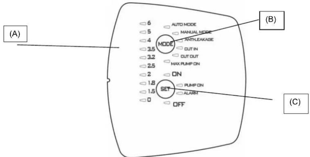
9.1OrnlaXapaKTepeNCTNK
| Описань | Параметри |
| Плata наруги, частOTи | 1x220-240В, 50/60 Гι |
| Показнik BBiMkh./ВИМКн. наруги | ● |
| Показнik BBiMkh./ВИМКн. ДВИтуна | ● |
| Показнik ТрИВог | ● |
| Показнik ТИСКу | ● |
| Показнik рекIMу | ● |
| АВТOMатч neuropи рекIM | ● |
| ЧУний рекIM | ○ |
| Зхисп пооти робoting "ВСуху" | ● |
| Зхисп пооти витOKу | ○ |
| Зхисп Мaksим. перiod робoting | ○ (30 xВИлии) |
| ТSCK Cut-in | ОпераMHнe (1,5 - 3,0 6ap) |
| ТSCK Cut-out | ○ (Cut-in + 1 6ap) |
| АВТOMатч neuropи заловань | ● |
| Кнорки Вибopy | ● |
-ΦIKCObAHa;O=NepemKaHHA
9.1.1 OncaHnДиCnJIeH:
(A) CbitIOioHNi INdkaTOp Tncky
IINOKa3AHNTHNCY BID 0do66ap BNKOpNCTOByOTbcra 10 cBITIOIOIB.Pn 3MIH CNTcEMN TNCKY CBITNOIOBNBIDNOBIDHO BMNAIOBTBCa aBO BMNAIOBTBCa.
YKPAHcBA
| Фунreichia | КонфICIENTа диспelo | Настоюкa | Reset Alarm (Скuidань Трumborи) |
| Auto Mode | AUTO MODE MANUAL MODE ANTHEAKAGE CUT IN | ON: Вмікань OFF: Вмікань | |
| Manual mode | AUTO MODE MANUAL MODE ANTHEAKAGE CUT IN | ON: Вмікань OFF: Вмікань | |
| Anti-leakage | AUTO MODE MANUAL MODE ANTHEAKAGE CUT IN | ON: Вмікань OFF: Вмікань | Наточун SET |
| Cut in | AUTO MODE MANUAL MODE ANTHEAKAGE CUT IN | 36iode�ен/3meшени | |
| Cut out | MODE ANTHEAKAGE CUT IN CUT OUT MAX PUMP ON | 36iode�ен/3meшени OFF: Вмікени | |
| Max pump on | MODE ANTHEAKAGE CUT IN CUT OUT MAX PUMP ON | ON: Вмікени OFF: Вмікени | Наточун SET |
(B Khonka-neremkauch pexmy MODE
PexumnIINB6Opy:
1) AUTO MODE;
2) MANUAL MODE;
3) ANTI LEACKAGE;
4) CUT IN;
5) CUT_OUT,
6) MAX_PUMP_ON;
Ioo6 po36JokyBn Bu6ip cyHKui Ha "MODE", HATNCHTN KHONky "MODE" I TpIMaTn I B HATNCHTOMy nnoXeHHi Ha npotra3i 5 cekyHd.
HaTnchTyN“MODE (PEXKIM), 06B Bn6paTn 6aKaHn pexM po6Otn (AUTO_MODE a6o MANUAL_MODE) BheCtN 3mHn B npametpn (CUT IN Ta CUT OUT) a6o 06 3aIaTn p4n FyHKuii (ANTI-LEAKAGE ta MAX PUMP ON).PiJ qac Bb6opy CbitlnoiD Bn6paHOi FyHKuII noHnae 6bnMaTn. Picn NOBepHeHH B AUTO_MODE aKTHBn FyHKU BIDobpaKaIOBcra 3a DOnOMOrIO NoCTIHORO rOpHH B iINOBiDHorO cBITNOIOda. NIB. naparpa2 (OnncAHn FyHKuii).
INdkaTopnB“MODE"
AUTO MODE: Hacoc npaioBaTmE B aBtOMaTHOMy pexkmi, nB. 9.2.1
MANUAL MODE: Hacoc npaioBaTMe B pyHOMy peXIMi, nB. 9.2.1; KopncTyBaU BpiIyBaTmE, KOJI N BMKATn Ta BmIKaTN HACOC 3a DOnOMOIO KHOKN "SET". SET-ON yBIMKHeHNI SET-OFF BmIKHeHNI.
CUT-IN:peryIIOBAAHH TnCKy (3aBXKn 3aJIAHe) MinImaIbHn TnCK, HIXKye JKOHO HAcOC BMNKAeTbcra, 3aJaETbcra BpaMKax Bi1,5do3,06ap,HacpOka BiD BnPo6HnKa 1.86ap; HAcOC BMNKAeTbcra TAKOX y TOMy BnPaAky,RAUo 3HaueHHa NOTOKy CknaademHe 1,5 n/xB., BCTaHOBJeHOro Bnpo6HnKOM.
CUT-OUT: peryIIOBAAH TNC Ky (He 3aJiaHe) 3NaeHHA TNC Ky, Bnue koro HAcOC BmNkaetbcr, BiD Bnpo6Hka HAcTPOKa dopiBHOE "CUT-IN" + 1 cbiIIOJOn, II MoKHa 36IbUnTu Do 3.5 6ap (50.8 psi).
YKPAHcBA
Ioo 3aioiTuO cyHKuO, Bn6paTn ii, HATNCKAouH Ha "MODE" do Tnx nip, NOK BiINOBiDn CBIIOJIOc CUT-OUT He noUHe 6JIIMaTn, nCIA:
1) HataChicb SET npotraom 10 ckyHd pO36nokyBaHHaYHKcii (npu cby 3aropTbcr IHdkaTopn 3haeHb TnCKy),
2) Hatnchitb SET nra o6paHna 6aXaHoro 3aueHHa,
3) DnB BMKHeHHa CyHKtB BCTaHObit 3HaueHHa cut-out Ha 0 [6ap a6o psi].
4)BnDITb3MeHIOHaJauWtYBaHHaHTNCyBmMODE.
PIM: 3NaueHnCUT-OUT moXHa 3miHmu JIWE nicra po3bNOkyeAHn fynkuJ uXOM hamucHeHH KhoNku SET npomzom 10 cekyhd. JaKo npomzom 1 cekyHDu He bde HamucHeHO Ha XODHy KhoNky, fynkuJ 3HO8 3a6NoKyembcr.
ANTI-LEAKAGE: 3axnT npOTn BnTOkIB. LIO cyHKUIO MOKHa 3aIjTn a6o De3aKTbByBaTn. PnHacTpOkaBID Bnpo6nka BOHa de3aKTBOBaHa. Raio uA cyHKUia 3aIjHa, To y BNadky BMnKaHHr HAcocy 6iJbwe 6 pa3ib Ha npotra3i 2 XbuiHn HACOC BmUKaCTbc, i Ndaetbc rHnI pno NOMNky 3a donomoro YoepBOHorO, NOBInbHO 6nmaOuro CBITNOjOHa Ha "ALARM".
Ioo3aioTn 0yHKIO, B6patn II, HataNcKaOuH Ha "MODE"do Tnx nip, noKn BiIOBIDHm IcBtNoiOid He nooHe 6IImatn, nicra zboro HataNcKATn Ha SET,doKn He yBIMKHeTbcra CbitNoiOid ON". 1o5 de3akTNByBaTn 1o OyHKUIO, HataNCHTuHa "SET" i ytpMByBatn do Tnx nip,doKn cBtNoiOid He Bkaxe Ha OFF.
IicnyuyeHH npuHn TpBOrn BKOHaTn CkHaHcNrHaNy TpBOrn, kUO BiN ue aKTHBn, nB.9.2.3.
MAX PUMP ON: mKcImaJIbHn nepioD pOBoTn. LIO fYHKUIO MOxHa 3aIaTIa 6o De3aKTHyBaTn. Ipn HAcToPkax BiD BpO6HnKa BOHa de3aKTUBOBAHa. JIKIO Ue fYHKUia 3aIaHra, To NICIA 6iNbU, HIX 30 XBUNH HepepeBHOi po60Tu HACOC BmNkaETbcA, npu cboMy He nOdaTeBCra HIAKO rCnHaLy npo NOMNKy.
L4yHkui BnKOpNCTOBYcBcIgToro, 3axntu yctaHOky BnnaKy 3aTyTOB biKpNToro KpaHy, noIKoJKeHHr Tpy60npOBOy, a TaKox npn BnKOpNCTAHH B iprauiHnx CnCTeMax.
Ioo 3aiaiTuO yHKuo, Bn6paTn II, HataNcKaOHn Ha "MODE" do Tnx nip, nOK BiINOBiHN iCBITIOio MAX PUMP ON He yBIMKHebcra, nicla UBO rHaNTCKaTHn Ha SET, DOKN He yBIMKHebcra CBITIOio "ON". Ioo de3akTNByBaTHn IO OyHKUHO, HATNCHTu Ha "SET" iYTPMByBATn Do Tnx nip, DOKN CBITIOioH He Bkaxe HA OFF.
(C) KhoNka-NepeMnKaU SET
PexnMn DnBbOpy:
1) Reset Allarmi (CkndaHnTpVBor).
2) 3aioe/de3akTbBye B MODE (MAX_PUMP_ON, ANTIILEACKAGE).
3) 36inbuye napametpn B MODE (CUT_IN; CUT_OUT).
4)ДиИгун ON/OFF B MANUAL MODE.
5) Hacoc yBimKHeHn/Hacoc B pexkmi OuyKaBaHHB AUTO MODE.
HaTnCHyTN "SET", 3oB BHeCTN 3mHb N napametpn; B TOMy BnnaKky, KOnr ropntb CbitnoioJHa MODE-CUT IN a60 MODE-CUT OUT, 3haeHHa 6yde BiOobpaKaTncra Ha CbitIOIOdHi nAneI NOKa3aHHa TnCKy. RaHcTaHa "SET, To ce 3haeHHa 6yde 3bihSyBaTnca. Iicra yCTaHOBKn 6axaHO r 3haeHHa BnTu 3 peXIMy BHeCEHHa 3MH, HATnCHyBUn dIra cyboro Ha "MODE" i nepeBIBuN CbitnoioJHa MODE-AUTO ta SET "ON" yBIMKHeHO.
HaTnckatn Ha SET TAKoK dIra TORO, 063aIytn/Je3akTuByBatn FyHKiAnti-leakage (3axnCT npOTn BnTOky) Ta Max pump On (MaKcIM. nepioD po6ToN). Pic7n Bn6bpy FyHKi3a Donomoro KhoNk "MODE" II MoXHa 3aIyTN, RaIO Bn6paTn SET-ON, a6o De3akTuByBatn, kAIO Bn6paTn SET-OFF.
B pexmi "MANUAL" (PYHNI) KhoNka SET cnyKntb taKoX dIra TORO, 06 BMnKaTn Ta BmNkAtn HAcOC, npu cboMy cbTIIOJIOB BMNaeTbcra Ha "On" afo "OFF".
B abTomatnuyhomy pexmi AUTO-MODE Khonka SET cnjxntb nra akTnaui "ON" a6o nepebeeHHi B pexm OiyBaHHa "OFF".
PUMP ON: nokakvn, 10 biinobidae po6oymy DnBny.
9.2 OnncaHHaYHKui
9.2.1 Hacoc BBIMKH/BUMKH (AUTO MODE, MANUAL MODE)
Функ肃 Cut out De3akTnBOBaHa kkuo BCTaBnTN BnKy B po3eTKy, cnepy npobOnTbcn nepebipka po60tn CBITIOIOJB, a notim HACOC BMnKaETbcn Ha 10 cekyHd.
Функя Cut out 3aДянha RaIO BCTABNTBnBnky Bpo3eKу,Ha npOra3i nepuX 3ceKHy npOBOHbCpeBipka po60Tn CBITIOIOIB (BMKAHH CBITIOIOda 0 3aBxDN BkA3ye Ha HArBHiCTb TnCKy), a NOTIM 3a 3AMOBvBAHHM BMKAeTbcR peKIM "AUTO MODE" Ta 3aropTeBCB CBITIOINikatop ON". HAcoc NOHe pauBoATn, RaIO TNck 6ynde HIXKHM 3a 3Na NotOKy 6yde HIXKYe MINImaIbHO 3HaueHHN NotOKy Cut-in. HAcoc pauBoAtme Do Tnx nip, DOKN TnCK 6yde HIXKHM, HIX 3HaueHHN CUT-OUT, nicJa DOcraHHeHHN HCoTO 3HaueHHN HAcoc BMNAeTbcS He3aJIexHo BiD CNJIN NOTOKY.
Y BnnaKy Bn6bpy puHoro peKmMy "MANUAL MODE" nCJNa HATNCKaHH Ha KHONy "MODE" HAcOC YBIMKHeTbcR, RaIoo roPntb CbitIOioD ON; kIIO Hi, To nCJNa HATNCKaHH Ha SET" HAcOC BmMkaeTbcR, i 3aropraetbcrCBITNOIOID OFF. KoI Naoc noUhe npauOBaTu, BiN cnePuy BMkAeTbcR B peKmI 3AJINBAHHJ.
N. B. IpekeohatncB TOMy, 0o Bci iHctpyku3 yCTaHOBKn HAcOCy 6yIN DoTPMaHI, a Cam HAcOC NOBHicTIO 3anOBHeHn BOIOU.
9.2.2Φa3a3aJIbHaHH
KoHACOC NOHe npaIOBAtn, BIn CnpSy BMNkAcTbC B pexMIM3aJIINBaHH; nI qac ciEi f a3i, kAIO He 6yde BnBNeHO TcCKy Ta cnnn NotOKy, DBrHyN npaIOBATmme Ha npotra3 XbUNIH, nicr yoro nepeJe B CTAH TpIBOn B 38'3ky 3po6TOO "BCyX". JaNo Ha npotra3i cboro INTePbany Yacy Byde BnBNEHO npCvTHicTb TcCKy Ta NOTOKy, NoCHETbc4 Pa3a 3aJIINBaHH, nicr yoro HACOC npaIOBATmme B HopMaIbHOMy pexMIM.
YKPAIHcBA
9.2.3 CkndaHnTpNBor
Y BnnaKy BnayBneHn TpNBOr 3aRopaeTbcraBIOiDn CbITnoIHnKaTOp cepBOHO KOJIbOpy Ha "ALARM". CkndaHn TpNBor BnKOHyEbCra ShJXOM OndHopa3OBOr H aTNCKaHHa KhoNky SET; kIIO npuHHy TpNBOr yCyHyTo, HAcOC IpaQoBaTmE B HopMaIbHomy pexMIM, kIIO Hi - hACOC 3HOBy nepeJe B CTaN TpNBOr.
9.2.4 POKAKK TCKy BBIMKH/BIMKH
Y npncythocti Tncky ropntb cbitnoiOid Tncky O Ha cbitnoiOidHni nanei. Raio Tncky Hemae, To cei cbitnoiOid He roptnb. N.B.Y Bunaikky Tpmbanix npoctoB peKomeHdyetbcra BmKHytn noaay Hanpyr, Dna zboR BuTartn BuNky 3 po3ETKn.
9.2.5 POKAKK HACOCY BBIMKH/BHMKH
Kuo Hacoc npauo, NOBHeH ropiu cnHi iHdkaTOp pObotn HAcocy "PUMP ON". Kuo Hacoc 3ynHaeTbcra, cei iHdkaTOp NOBHeH Bmukatnc.
9.2.6 Nokaxnk TpBor
Y BnnaKy HaraBHO 3aRopTbC KhoNka "ALARM", noCTiHm a6o 6nMaOHm CbitlOM.
Pobota "Bcyxy" (Dry-running): nocTiHNO BBIMKHeHn YepBOHn CbitIOHnKaTop
Bntik (Leakage): nobJIbHe 6nMaHHa.
Max Pump ON (hacoc npaioe ha npotrai 6inbwe, hix 30 xBnHH): 2 wBnKx 6nMaHH i nicna Hnx nay3a Ha npotrai doBworo npomixky acy.
HaTnChyTN "SET", 106 BnKoHaTH CkNdaHH TpNBor.
9.2.7 3axnCT BiD po6oTn "Bcyxy" (Dry running protection)
JaHACOC npaOe "Bcyxy", To Bxke uepe3 KjIbKa cekyHd (40 cek.) BiH 3ynHaeTbcra, Noaetbcra CnHaJ NOMNkn, BMKAeTbcra YepBOHNI CBITIOHINKATOp Ha "ALARM", IIO ropntb NOCTIHIM CBITNOm.
Yepe3 30 xBnHn nicna nepooi 3ynHKn Hacocy B cTaHi OFF 3dInchioetbca nepwa cnpo6a nobTopHoro 3anycky Ha npotrai
5xbnH. Jaio i cy cnpoBa BnBntbC HeBdAIOIO, To KxHa HAcTynHa cnpo6a 6yde 3diChOBatncpe3 KOxHi 30 XBNIH 3 MaKcImaIbHM UcNOM 3aynckib 48. Kaio Bci ci cnpoBn BnBnTbcra HeBdaIIMM, To HAcTynHi cnpo6b ydytb 3diChOBATncpe3 KOxHi 24 roDHN.
PnHaBHOCTI NOToKy Ta/abo TnCKy npncTpi ABTomaTHO BHXoNDt 3i CTaHy TpNBOrn 3axNCTy BiD pOBTu "BCxy".
PiCnA CkndaHn TpNBOrn, DnB. 9.2.3, HAcTyNa Cnpo6a Bye 3diChIOBaTnca Ha npOTa3i 40 cek.
Uo6 yCyHyTn npuHn Ta cKnHyTn TpNBOrn, nB. 9.2.3.
9.2.8 3axnCT npotu Bntokiv (ANTI-LEAKAGE)
LIOyHKUIO MOKHa 3aIIOBAtn a6o De3aKTbByBaTn, 3a 3aMOBcYBaHHM BID BINO6Hka BOHa De3aKTbBOBaHa. JkUO Ue yHKUia 3aIiHa, To y BNpAky BMKAHH HaCOCy 6 pIbwe 6 paIb HA npOTa3i 2 XBNH HACOC BIMNkaETbcra, i NOaETbcra CINHAN PNO NOMIKy 3a DonomorOu YepBOHOro, NobInbHO 6bnMaHOoro CbitNoioJa Ha "ALARM".
Uo6 yCyHyTn pNCHnTa cKHyTu TpNBOrn, nB. 9.2.3.
PpoeDypa 3aIIOBaanr onncana B n. Anti-leakage.
9.2.9 Max pump on
MaKcImaJIbHn nepioD pOBoTn. LIO fynKUIO MOxHa 3aIgTn a6o De3aKTHyBaTn. PnH NaCTpOJaX BID BnPo6HnKa BOHa de3aKTINBOBaHa. KaIIO U cyfHKUZ 3aIgHa, To nICr 6iNbU, HIX 30 XBNINH HepepeBHOI POBOTn HAcOC BmNKAeTBcR, PnI cboMpy NOaTeBCra CnHAn y BuIgIaI bIMaHnH iNDkAtoP a HA ALARM.
Lc yhkiy BnKOpNCTOBYeTBCI TOrO, 0o6 3axnCTHn ycTaHOBky y BnAaKy 3a6yTORO BiKpntoro KpaHy , noiKOJKeHHrtpbnpoody, a TAKoK npn BnKOpNCTaHHB iiprauiHnx CNTEmax.
9.2.10 Tpmbora daTnuka Tncky
Pnpctpi nepexoDHTB CTAH TpBNBOrn DaTCHKA TCKY, JAKIO 3HaueHHe TCKy BHXODNTb 3a BCTaHOBneHi po6Oi paMK (0-15 6ap). Hacoc BmNKAcETbcR, CKndaHH NOMUNK BiID6yDeTbcR, JIK TINbKN 3HaueHHe TCKy NOBepHeTbcR B pAMKn BCTaHOBneHoro diana3OHy.
9.3 Iepwn npck
9.3.1 Ppebipka cBtnoioiib
Pn nepwomy ncyk a6o b 6ydb-kyom yinom Bnnaiky nicBCTaBneHn BnKn Bpo3eKy KINBneHH npOBOntbc nepeBipka po60tn 20 cblnoioi, kpa Tpmbac Kibka cekynd i nd cac koi ycblnoioi BMnKaHObC no cep3i.
9.3.2 Nepwe 3aHaHH
AToMaTuHNo 3a 3AmOByBaHHm HAcO 6ye BpeKmi AUTO iHaCTpoEnn Ha ON.
PnUcbOMyMOKJIbI TpN HAcTynHdiHaCocv:
1) Notik e, ane TnCK Hn3bKn: HACOC BNXOHTb 3 a3n 3aINBaHHN NOuHnAc HopMaJIbHy po60Ty.
2) Tuck €, aile Hemae notoky: hacoc nepe6yBa B cIbomy cTaHi Ha npotrai 10 cek., a notim Bmikaetcra.
3) Hemae Hi Notoky, Hi Tncky: Upees np6n. 3 XBnHn Haoc BmKkaetbcr, i 3'ABJrEETbc NOBIDOMNEHn Ipo NOMNky "pOboTa BCxyy", Ha 0o BkA3ye yBIMKHeHn YepBOHn CbitIOiOd Ha SET-ALARM. 92.3.
9.4 HopMaIbHa po6oTa 3 De3aKTHBOBaHOH KyuCIO CUT-OUT (BID BnpO6HnKa)
Pn de3aKtBBOBaHm fynkui Cut-out moXnBi HacTynHi DHaHocca:
Hacoc BMnkaetbca, kio e notik, a6o B pa3i BiCyTHOCTI TCKy, TCK HxKHe, HIX 3HaueHHa CUT IN (Ha npotra10 Mcek.)
YKPAHcBA
HACOC BIMKAcTbC, RaIO Ha npot3i 6e3nepepBHorO npomixky aycy B 10 cek. e Tnck, ane Hema notoKy. Pid yac HopmaIbHOoi po6oTn CbitnoioD CUT OUT 6yde BIMKHeHH. DnA BHeCEHHa 3mH B HacTpouKn dN.B. 9.1.1.B.
9.5 HopmaNbHa po6oTa 3aiaHIO yHKueo CUT-OUT
Pn3aiaHni yHKui Cut-out moKnBi HacTyHi iHaCoca:
- Hacoc BMnkaetbca, kku Tnck Hnxhe BcTaHOBHeHoro 3HaueHHaCkCy CUT IN.
- Hacoc BmMkaetbca, kkuo Tnck Bnue BCTaHOHeHOrO 3Naehra Tccky CUT IN.
Iiud HopmaJIbHOIpo6TOINCBITIOIDCUTOUT6yde yBIMKHeHm.IJRA BHeCEHHaMnBHaCTpOKnDVB.9.1.1.B
10.3ACTEPEKHI 3AXOIN
P3K 3AMEP3AHHЯ: kuo Hacoc 3aIIuAeTbcB B Hepo6oy cTahi npi Tempepatypi HnKYe 0^ , cIi nepekoHaTnc B TOMy, 00 B HbOMy Hema3aIIuKy BoN, 00 npi 3amep3aHHi MOKe N0WKoDHTn PAnCTmacOBi YAcTHnHn HaCoCA. IicnBnKOpNCtAHn HaocCy dIy BiDBeHeHH peOvHN, kci CxINbHi Do HAKOnUeHb Ta BiKNaDeHb, a6o nicn PepeKauyBaHH XIopOBaHO BODn Ioro CInd IpomNTuNcTOU BOHO; dIy IpomNBaHH CKOpNCtATnc CInbHM CTpyMeHem BoN, 00b 3anobirTu yTBopeHHIO BiKNaDeHb, 00 MoKvTh HeratNBHO BnInHyTN Ha EKcnnyatauHi xapakTepcntkn Hacocy.
11. DORJIAD TA TEXHICHE OBCJYROBYBAHH
Pn HopMaIbHnx yMOBax eKcnnyataaui eJeKtpoHaoc He noTppe6ye HiaKOro texHiHoro 06cNryOByaHH. B 6yDb-akomy pa3i Bci po6otn 3 pEmOnTy Ta texHiUHO o6cNryOByaHH cnid BuKohyBaTu TINbkNicN BiKIOuHeHH HaCOCy BiD MepeXi JxNBHeHH. Npeed Tm, Jk 3HOby yBIMKHyTu HAcOC nicN terxHiUHO 06cNryOByaHH Ta pEmOnTy, cnid nepeBipuTu, 00 Bin 3i6paHnn HaneXHM uHOM, Uo6 He CTBOpTu Ne6e3neHu CyTu aio Dn oc6 Ta MaHa.
11.1 Ynctka BCMOKTyBaIbHoro fInbTpa
(Ma1.3)
BidKnHouHTn HAcOC BiD MepeXi eNekTpHuOro XuBHeHHA.
CnpoKHTn Hacoc, BiKpNBnI Jnla CbOro 3NHBny npo6ky (6); nonepaHbO nepeKpnTn 3acNIHK paHIe no IHHI (RAIO MAOTBC).
Bikpyntn KpniuKy kamepn fInbtpy BpyHy a6o 3a DonomorOIO CneiaIbHOrO IHCTpyMeHTy, IO Hadaetbcr B KOMnneKTI.
- BntTn 3Bepx6nok fInbtpy.
- Ppomntn cKJrHky niD cTpyMeHem npoToUHOI BOuN Ta npOuHCTnTn pInbTp 3a DOnOMOrO M'RAKOI uITKn.
3HOBy BCTaHOBHTn FInbTp Ha Micue, BIKOHaBUn Bci OINcahi BnIe dII B 3BOPOTbOMy NOPdKy.
11.2 Unctka HnK
(Ma1.4)
BiiKnHouHTn HAcoc BiD Mepeksi eNeKTPuHOrO XINBHeHHa.
3Hrtn npo6ky HPK (5) 3a donomoroo cneiaJIbHorO IHCTpyMeHTa, UO HadaeTbcra B KOMnIKeTI.
3HrTHN HENOBOPOTn(3anipHm)KJanaH HPK Ta nouchTHTnooro, MaJ.9
Bukohatm MOHTaK y 3BOPOTbOMy npraKy.
12. NOUyK

Ipeed TMM, k p03noOHnTn noyK HenoJaOK, Heo6xIdHO Bld'cHaTHn HAcoc BiD dKepeJ eNEKtpuHOrO XNBHeHHa(BNTAHTN BNky 3 po3eTK). RaKIO Ka6eJIb XNBHeHHa a6o HAcoc B 6yDb- kI yoro eNEKtpuHHi YactHI nOwKOJXeHI, peMOHT Ta 3amHy NOBHeH 3diChIOBaTN BnPo6Hk A6o yOBHOBaHexHn Hm cHTp TexHInx NoCnyr, a6o TexHInH cneuaianict 3 BiIDNOBIAHO KBAIIfikaicIO, 9o Do3BOJae 3ano6iRTn 6yd-akomy pn3NU.
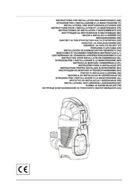
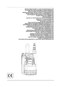
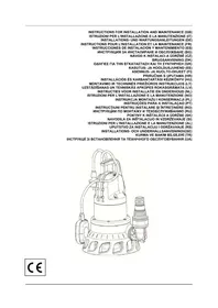
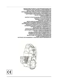
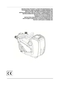
- INDEX
- WARNING
- APPLICATIONS
- ENGLISH
- PUMPABLE LIQUIDS
- TECHNICAL DATA AND LIMITATIONS OF USE
- MANAGEMENT
- Storage
- Transport
- Weight and dimensions
- WARNINGS
- INSTALLATION
- ELECTRICAL CONNECTION
- START-UP
- ELECTRONIC CONTROL INTERFACE
- Overview of the features
- Description of the display:
- Pressure indicator LEDs
- MODE selection button
- Indicators on "MODE"
- SET selection button
- Description of the functions
- Pump ON/OFF (AUTO MODE, MANUAL MODE)
- Priming phase
- Alarms reset
- Power ON/OFF indicator
- Pump On/off indicator
- Alarms indication
- Dry running protection
- ANTI-LEAKAGE
- Max pump on
- Pressure sensor alarm
- First start up
- Test on LEDs
- First priming
- Normal operations with CUT-OUT disabled (factory setting)
- Normal operations with CUT-OUT enabled
- PRECAUTIONS
- MAINTENANCE AND CLEANING
- Cleaning the suction filter
- Fig.3
- Cleaning the NRV
- (Fig.4)
- TROUBLESHOOTING
- GUARANTEE
- ITALIANO
- INDICE
- Bouton de selection SET
- Indication pompe On/off
- TEXHNUECKN DAHHN IN OPGAHUHEHNA 3A YIOTPEBA
- CTONAHNCBAHE
- CbxaheHne
- TpaHcnpot
- БылгAPСКИ
- Terno pa3mepn
- NPEyNPEKKeHnA
- MOHTIPPAHE
- ENEKTPNUECKO CBbP3BAHE
- ББЛГAPСКИ
- CTAPTINPAHE
- ENEKTPOHEH INHTEPΦEIC 3A YIPTABLHeH
- O63op Ha xapaKTepeNCTNKKeT
- OncaHne Ha dncnpe:
- CBeToDnOHN HnDnKaTOpN 3a HaJIraHe
- Bytoh 3a n36op MODE
- HdkKaTOpn 3a“MODE"
- Bytoh 3a n36op SET
- Onncahne Ha yHKunTe
- Nometa ON/OFF (AUTO MODE, MANUAL MODE)
- Φa3a Ha 3aJIbBaHe
- Pecet anapm
- INHdkaun on/off 3a HanpexeHne
- INHdkauon/off 3a nomnata
- INHdkaun3a aJapMnTe
- 3aunita cpeu cyx ctap (Dry running protection)
- 3aunita cpeu teyobe (ANTI-LEAKAGE)
- Anapma Ha ceH3opa 3a HnIraHe
- 9.3Пьрвocтарпанe
- TectBaHe Ha CBeToDnOdnte
- TbPBO 3aJIbBaHe
- HopMaHn onepaunnc DeakTNBupan CUT-OUT (pa6pnuHo)
- HopmaHHn onepaunc cakTNBupan CUT-OUT
- INPEДПАЗHIМЕРКI
- NOДРьЖКА И NOЧИСТBAHЕ
- NocntBaHe Ha acnnpaunHnHa tpeWetka
- (Фur.3)
- Vaelgeknappen SET
- Evεiη Σuvayepμw
- MODE-valintapainike
- SET-valintapainike
- Valittavat tilat:
- Oznaka pumpe On/off
- SIURBIMUI TINKAMI VANDENYS
- TECHNINIAI DUOMENYS IR NAUDOJIMO APRIBOJIMAI
- WAARSCHUWINGEN
- Antilek-beveiliging (ANTI-LEAKAGE)
- INNHOLDSFORTEGNESELL
- LED-varsellamper for trykk
- Wskazniki cijsenia diodowe led
- DADOS TECNICOS E LIMITAÇOES DE USO
- Buton de selectare MODE
- TEXHNUECKNE DAHHbIE N OTPAHNueHENB 3KcIyATAUIN
- 4.3KcnnyATAUIN
- CknaIupoBaHne
- PYCCKN
- TpaHcnpTnpoBka
- Bec npa3Mepbl
- NPEynpKxDEHnA
- MOHTAK
- 3ЛЕКТРИСЕСКОЕ NOДКЛIOΥЕНЕ
- 8.3ANYCK
- 3NEKTPOHbI INHTEPFENC yIPABNEHNA
- O63op xapaKTepeHcTnK
- OncaHne nCnJIe:
- INHdNkaTopbI-CBETOHObI daBHeHn
- Khonka Bb6opa SET
- Onicahne dyHKn
- Hacoc ON/OFF (AUTO MODE, MANUAL MODE)
- Φa3a HANOJIHeHn
- C6poc aBapnHbix cRHaNoB
- Yka3aHHe HapxKeHnBkN./BbIKN
- Yka3aHne Hacoca BKn./BbIKn
- Yka3aHHe Ha aBapnHbIe cHrHaIbI
- 3aunTa oT pa6oTb6e3 BoDbI (Dry running protection)
- 3aunTa oT yTeueK (ANTI-LEAKAGE)
- INPEIOCTOPOXHOCTN
- TEXHINCHECKOE OBCJLYXKIBAHNE I YNCTKA
- OuicTka qnIbTpba BcacbBaHna
- (Cxema 3)
- Ynctka NRV
- (Cxema 4)
- NOVCK HENCPABHOCTEIN
- Teza in velikost
- OPOZORILO
- Tregues trysnie me led
- SHQIP
- Butoni i selektionimit MODE (Menyra)
- Treguesitper“MODE"
- Taster za odabir SET
- Test led lampica
- Prvo početno usisavanje
- Normalne operacijs onemogucenom postavkom CUT-OUT (fabrički)
- Normale operacoes omogucenom postavkom
- Kuru calismaya karsi koruma (Dry running protection)
- ENEKTPNUEH NIKIOUOEHNA
- YKPAHcBA
- NOYATOK POBOTN
- IHTEPΦEIC ENEKTPOHHO YNPABNIHH
- 9.1OrnlaXapaKTepeNCTNK
- OncaHnДиCnJIeH:
- CbitIOioHNi INdkaTOp Tncky
- (B Khonka-neremkauch pexmy MODE
- INdkaTopnB“MODE"
- KhoNka-NepeMnKaU SET
- OnncaHHaYHKui
- Hacoc BBIMKH/BUMKH (AUTO MODE, MANUAL MODE)
- 9.2.2Φa3a3aJIbHaHH
- YKPAIHcBA
- CkndaHnTpNBor
- POKAKK TCKy BBIMKH/BIMKH
- POKAKK HACOCY BBIMKH/BHMKH
- Nokaxnk TpBor
- 3axnCT BiD po6oTn "Bcyxy" (Dry running protection)
- 3axnCT npotu Bntokiv (ANTI-LEAKAGE)
- Tpmbora daTnuka Tncky
- Iepwn npck
- Ppebipka cBtnoioiib
- Nepwe 3aHaHH
- HopMaIbHa po6oTa 3 De3aKTHBOBaHOH KyuCIO CUT-OUT (BID BnpO6HnKa)
- HopmaNbHa po6oTa 3aiaHIO yHKueo CUT-OUT
- 10.3ACTEPEKHI 3AXOIN
- DORJIAD TA TEXHICHE OBCJYROBYBAHH
- Ynctka BCMOKTyBaIbHoro fInbTpa
- (Ma1.3)
- Unctka HnK
- (Ma1.4)
- NOUyK
Brand : TALLAS
Model : DEBOOST 850
Category : Water pump