USER MANUAL D-ECONCEPT 1000 TALLAS
INSTRUCTIONS FOR INSTALLATION AND MAINTENANCE (GB)
natural_image
Technical line drawing of a mechanical device with no visible text or symbols
ENGLISH Pag. 1
ITALIANO Pag. 23
DEUTSCH Seite 45
FRANÇAIS Page 67
ESPAÑOL Pág. 89
ČESKY strana 111
SUOMI sivu 133
NEDERLANDS Pag. 154
РУССКИЙ Стр. 176
SLOVENSKO Str. 199
INDEX
1. GENERAL 2
1.1 Built-in inverter 3
1.2 Integrated electropump 3
1.3 Built-in filter 4
1.4 Technical characteristics....4
2. INSTALLATION 4
2.1 Hydraulic connections....5
2.2 Loading Operation....5
3. COMMISSIONING......6
3.1 Electrical Connections....6
3.2 Configuration of the Integrated Inverter 6
3.3 Priming 6
4. THE KEYPAD AND THE DISPLAY....7
4.1 Access to menus....7
4.2 Structure of the menu pages 9
4.3 Enabling and disabling the motor....9
5. MEANING OF THE INDIVIDUAL PARAMETERS ...... 9
5.1 User Menu.... 10
5.1.1 RS: Rotation speed display 10
5.1.2 VP: Pressure display 10
5.1.3 VF: Flow display 10
5.1.4 PO: Absorbed power display.... 10
5.1.5 C1: Phase current display 10
5.1.6 HO: On time counter 10
5.1.7 HW: Motor pump operating hours count 10
5.1.8 NR: Number of start ups.... 10
5.1.9 EN: Energy absorbed counter 10
5.1.10 ES: Saving.... 10
5.1.11 FC: Pumped fluid volume count 10
5.1.12 VE: Version display 10
5.1.13 FF: FF: Fault log display.... 10
5.2 Monitor Menu 10
5.2.1 CT: Display contrast 11
5.2.2 BK: Display brightness 11
5.2.3 TK: Backlight switch-on time 11
5.2.4 TE: Dissipator temperature display 11
5.3 Setpoint Menu 11
5.3.1 SP: Setting the setpoint pressure.... 11
5.4 Manual Menu....11
5.4.1 RI: Speed setting.... 12
5.4.2 VP: Pressure display 12
5.4.3 VF: Flow display 12
5.4.4 PO: Absorbed power display.... 12
5.4.5 C1: Phase current display 12
5.5 Settings menu 12
5.5.1 RP: Setting the pressure fall to restart 12
5.5.2 OD: Type of plant 12
5.5.3 MS: Measuring system 12
5.5.4 FY: Enabling dispensed volume block 12
5.5.5 TY: Enabling pumping time block.... 13
5.5.6 TY: FH: Dispensed volume 13
5.5.7 TH: Pumping time.... 13
5.6 Advanced Settings Menu 13
5.6.1 TB: Water lack blockage time.... 13
5.6.2 T2: Delay in switching off 13
5.6.3 GP: Proportional gain coefficient.... 13
5.6.4 GI: Integral gain coefficient.... 13
5.6.5 RM: Maximum speed 14
5.6.6 AY: Anti Cycling.... 14
ENGLISH
5.6.7 AE: Enabling the anti-block function 14
5.6.8 AF: Enabling the anti-freeze function 14
5.7 RF: Fault and warning reset.... 14
6. PROTECTION SYSTEMS.... 14
6.1 Description of blockages 14
6.1.1 "BL" Anti Dry-Run (Protection against dry running).... 14
6.1.2 Anti-Cycling (Protection against continuous cycles without utility request)) 15
6.1.3 Anti-Freeze (Protection against freezing of water in the system) 15
6.1.4 "BP1" Blockage due to fault of the delivery pressure sensor (system pressurisation).... 15
6.1.5 "PB" Blockage due to supply voltage outside specifications.... 15
6.1.6 "SC" Blockage due to short circuit between the motor phases 15
6.2 Manual reset of error conditions.... 15
6.3 Self-reset of error conditions 15
7. RESET AND FACTORY SETTINGS 16
7.1 General system reset.... 16
7.2 Factory settings.... 16
7.3 Restoring the factory settings.... 16
8. PARTICULAR INSTALLATIONS .... 17
9. MAINTENANCE 18
9.1 Accessory tool 18
9.2 Cleaning the Built-in Filter 18
9.2 Emptying the system 19
9.3 Non-return valve 19
9.4 Motor shaft....20
10. TROUBLESHOOTING 20
- DISPOSAL 22
- GUARANTEE 22
KEY
The following symbols have been used in the discussion:

Situation of general danger. Failure to respect the instructions that follow may cause harm to persons and property.
Situation of electric shock hazard. Failure to respect the instructions that follow may cause a situation of grave risk for personal safety.
Notes
WARNINGS

Read all this documentation carefully before installation.
Take out the plug before any intervention. Absolutely avoid dry operation: the pump must be activated exclusively when it is immersed in water. If the water is finished, the pump must be deactivated immediately, taking the plug out of the socket.
Protect the electropump against inclement weather
Pumped liquids
The machine has been designed and made for pumping water, free from explosive substances and solid particles or fibres, with a density of 1000 Kg/m^3 , a kinematic viscosity of 1 mm^2/s and non chemically aggressive liquids.
Failure to observe the warnings may create situations of risk for persons or property and will void the product guarantee.
1. GENERAL
Applications
For fixed or portable installation in water supply and pressurisation systems for domestic use, small scale agriculture, vegetable plots and gardening, domestic emergencies and the hobbies industry in general.
The product is an integrated system consisting of a self-priming, multi-stage centrifugal motor pump, an electronic circuit for control (inverter) and a filter to remove any incoming impurities.
ENGLISH
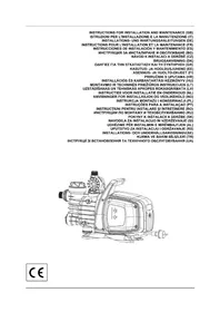
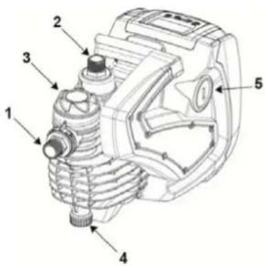
With reference to Fig.1, the system has the following user interface points:
- Suction connection (inlet))
- Delivery connection (outlet))
- Port for filling and filter maintenance
- Drainage port
- Port for bleeding and extraordinary maintenance Non-return valve
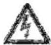
- Control panel and status Display
- Grip for lifting and transport
- Port for extraordinary maintenance Motor Shaft
Figure 1
1.1 Built-in inverter
The electronic control integrated in the system is of the type with inverter and it makes use of flow, pressure and temperature sensors, also integrated in the system. By means of these sensors the system switches on and off automatically according to the utility's needs and it is able to detect conditions of malfunction, to prevent and indicate them.
The Inverter control ensures different functions, the most important of which, for pumping systems, are the maintaining of a constant pressure value in delivery and energy saving.
- The inverter is able to keep the pressure of a hydraulic circuit constant by varying the rotation speed of the electropump. In operation without an inverter the electropump is unable to modulate and, when there is an increase of the request for flow, the pressure necessarily decreases, or vice versa; this means the pressures are too high at low flow rates or too low when there is an increased request for flow.
- By varying the rotation speed according to the instantaneous request of the utility, the inverter limits the power supplied to the electropump to the minimum necessary to ensure that the request is satisfied. Instead, operation without an inverter contemplates operation of the electropump always and only at maximum power.
For the configuration of the parameters see chapters 4-5.
1.2 Integrated electropump
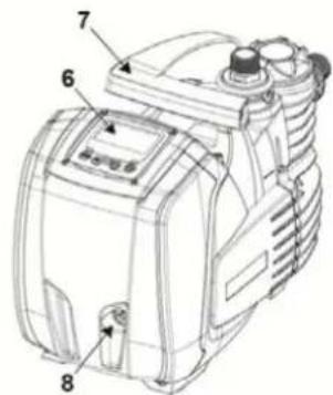
The system has a built-in centrifugal electropump of the multi-impeller type driven by a water-cooled three-phase electric motor. Cooling of the motor with water rather than air ensures less noise in the system and the possibility of locating it even in recesses without ventilation. The graph in Fig.2 shows the curve of the hydraulic performance.
By automatically modulating the rotation speed of the electropump, the inverter allows it to shift its work point according to necessities to any part of the area subtended by its curve, to keep the set pressure valve constant. The red curve highlights the behaviour of the system with setpoint 3.0 bar.
line
| Q (lt/1') | H (mt) - Blue Line | H (mt) - Red Line |
| --------- | ------------------ | ----------------- |
| 0 | 60 | 30 |
| 5 | 58 | 30 |
| 10 | 55 | 30 |
| 15 | 52 | 30 |
| 20 | 49 | 30 |
| 25 | 46 | 30 |
| 30 | 43 | 30 |
| 35 | 40 | 30 |
| 40 | 37 | 30 |
| 45 | 34 | 30 |
| 50 | 31 | 30 |
| 55 | 28 | 30 |
| 60 | 25 | 25 |
| 65 | 22 | 20 |
| 70 | 18 | 15 |
| 75 | 14 | 10 |
| 80 | 10 | 5 |
| 85 | 5 | 0 |
Figure 2
This means that, with SP = 3.0 bar, the system is able to ensure a constant pressure to utilities that require flow rates between respectively 0 and 55 litres/minute. For higher flow rates the system works according to the characteristic curve of the electropump at maximum rotation speed. For flow rates lower than the limits described above, as well as ensuring constant pressure, the system reduces the absorbed power and therefore the energy consumption.

The above performances are to be considered measured at ambient temperature and water at about 20^ C, during the first 10 minutes of motor operation, with water level at suction at a depth of no more than 1 metre.

As the suction depth increases, the performance of the electropump decreases.
1.3 Built-in filter
The system incorporates a built in filter cartridge at the pump infeed to prevent any suspended impurities in the water. The filter cartridge is of the mesh type, with washable 0.5 mm mesh. The filler port (3-Fig.1) allows access to the filter cartridge for its routine maintenance operations (Sect.9.2). The transparent part of the filler port makes it possible to check whether the cartridge needs to be washed.
1.4 Technical characteristics
| Topic | Parameter | |
| ELECTRIC POWER SUPPLY | Voltage 1 ~ 220-240 | VAC |
| Frequency | 50/60 |
| Maximum power 1000 W | |
| Maximum current | 4.8 [Arms] |
| Current dispersed to the ground | <3 [mArms] |
| STRUCTURAL CHARACTERISTICS | Overall dimensions | 483 x 236 x H322 mm |
| Empty weight (excluding packaging) 12.3 kg | |
| Protection class | IP X4 |
| Insulation class of the motor | F |
| HYDRAULIC PERFORMANCE | Maximum head 60 m | |
| Maximum flow rate | 85 l/min |
| Priming <5min a 8m | |
| Maximum working pressure | 6 bar |
| WORKING CONDITIONS | Max liquid temperature | 40 °C |
| Max environment temperature | 50 °C |
| Environment temperature of storage | -10÷60 °C |
| H min 0 m | |
| FUNCTIONALITY AND PROTECTIONS | Constant pressure |
| Protection against dry running |
| Antifreeze protection |
| Anticycling protection |
| Anti-locking protection |
| Motor overload protection |
| Protection against abnormal supply voltages |
Value
Hz
Table 1
2. INSTALLATION

The system is designed for use “in a closed place”: the system is not designed for fixed installation outdoors and/or directly exposed to atmospheric agents. It can be used outdoors as a non-fixed application: transported to the site for use and stored indoors at the end of the operation.
The system is designed to be able to work in environments where the temperature remains between 0^ C and 50^ C (on condition that the electric power supply is ensured: see par. 5.6.8 “anti-freeze function”).
The system is suitable for treating drinking water.
The system cannot be used to pump salt water, sewage, inflammable, corrosive or explosive liquids (e.g. petroleum, petrol, thinners), greases, oils or food productsi.
The system can suck up water with a level that does not exceed the depth of 8 m (he height between the water level and the pump suction mouth).
If the system is used for the domestic water supply, respect the local regulations of the authorities responsible for the management of water resources.
When choosing the installation site, check that:
- The voltage and frequency on the pump's technical data plate correspond to the values of the power supply system.
- The electrical connection is made in a dry place, far from any possible flooding.
- The electrical system is provided with a differential circuit-breaker sized according to the features indicated in Table 1.
- Earth connection must be ensured.
ENGLISH

The system cannot support the weight of the piping which must therefore be provided with other kind of support.
Risk of water temperature rising inside the pump: pump operation for a prolonged time without the distribution of water, or with reduced distribution, can cause an increase of the water temperature inside the pump up to a value such as to cause damage to property or persons at the time of distribution. This situation generally occurs after the pump has undergone a long series of switching on and off operations. It occurs typically in rigid systems (without an expansion vessel) and the causes may be:
- a small leak (even just a few drops) that causes a fall in pressure that restarts the pump, but does not allow a sufficient exchange of water
- too low RP values that do not allow the stabilisation of pressure and regular switching off
- an incorrect setting of the GI and GP gains which makes the adjustment swing
The situation is aggravated in the case of:
- a high setpoint (SP), which contributes to the distribution of greater power to the water
- very long switching off times T2 that contribute to prolong the time during which power is distributed to the water.
It is always good practice to position the system as close as possible to the liquid to be pumped.
The system must be operated only when positioned horizontally and resting stably on its rubber feet.
In case of fixed installation, make sure the position selected ensures access and visibility to the command and control panel (6-Fig.1).
In case of fixed installation, make sure sufficient space is provided to allow for routine maintenance of the built-in filter (Sect. 9.2).
In case of fixed installation, fit an On/Off valve on the suction side as well as the delivery side. This makes it possible to easily close the line upline and/or downline of the system for any maintenance and cleaning or for shutdown periods.
In case of fixed installation, the use of an expansion tank is recommended, to be connected on the delivery piping, so as to make the system elastic and protect it from water hammer. The capacity of the expansion tank is not binding (1 litre is sufficient), the recommended precharge is 1 bar less than the set point.
If the water is particularly loaded with foreign bodies and the number of cleaning operations on the built-in filter is to be reduced, install an additional external filter at the system infeed to stop the impurities.

The installation of a filter on intake causes a decrease of the system's hydraulic performance proportional to the loss of load caused by the filter itself (generally the greater the filtering power, the greater the fall in performance).
2.1 Hydraulic connections
The system ensures the declared performances only if piping with diameter not less than those of the openings of the system (1") are used at the inlet and outlet.
With reference to its position with respect to the water to be pumped, the installation of the system may be defined "above head" or "below head". In particular the installation is defined "above head" when the pump is placed at a level higher than the water to be pumped (e.g. pump on the surface and water in a well); vice versa it is "below head" when the pump is placed at a level lower than the water to be pumped (e.g. overhead cistern and pump below).
If the installation is of the "over head" type, install the suction pipe from the water source to the pump in such a way as to avoid the formation of goosenecks or siphons. Do not place the suction pipe above the pump level (to avoid the formation of air bubbles in the suction pipe). The suction pipe must draw at its entrance at a depth of at least 30cm below the water level and must be watertight along its whole length, as far as the entrance to the electropump. For suction depths of over four metres or with long horizontal stretches it is advisable to use an intake hose with a diameter larger than that of the intake aperture of the pump. If the suction pipe is made of rubber or flexible material, always check that it is of the reinforced vacuum-resistant type to avoid shrinkage due to suction.
If the installation is of the “positive suction head” type, avoid “goosenecks” and siphons in the suction piping and make sure it is water-tight.
The suction and delivery ducts must be connected to the system by means of the threads provided: 1 inch male thread on swivel connector made of technopolymer.

When making the connection airtight by adding material (e.g. Teflon, hemp,...) make sure you avoid excessive use of the gasket. under the action of a suitable tightening torque (e.g. long-handle pipe wrench), the excess material may exert abnormal forces on the technopolymer connector, damaging it permanently.
The swivel connectors make it easier to install the system.
2.2 Loading Operation
Installation above head and below head
Installation "above head" (par. 2.1): remove the Filler cap (3-Fig.1) by unscrewing it manually or using the tool provided, also remove the breather cap (5-Fig.1) using a screwdriver or the tool provided; then fill the system with clean water through the filler port (approx. 1 liter). As soon as the water starts flowing through the bleeding port, carefully screw the cap back on, top up further through the filler port and screw the filler cap back on until it comes to a mechanical stop. It is recommended to fit the non-return valve at the end of the suction pipe (foot valve) so as to be able to fill it quickly too
ENGLISH
during the loading operation. In this case the quantity of water necessary for the loading operation will depend on the length of the suction pipe
Installation "below head" (par. 2.1.): if there are no check valves between the water deposit and the system (or if they are open), it loads automatically as soon as it is allowed to let out the trapped air. Then slacken the breather cap (5-fig.1) just enough to release the trapped air; this allows the system to get filled completely. Supervise the operation and close the bleeding port as soon as the water flows out (it is advisable to provide an On/Off valve in the suction piping section and use it to control the filling operation with the cap open). Alternatively, if an On/Off valve is present on the suction piping, the filling operation can be carried out in a manner similar to that described for the suction lift installation.
3. COMMISSIONING
3.1 Electrical Connections
To improve immunity to the possible noise radiated towards other appliances it is recommended to use a separate electrical duct to supply the product.
Attention: always respect the safety regulations!
Electrical installation must be carried out by an expert, authorised electrician, who takes on all responsibility.
The system must be correctly and safely earthed as required by the regulations in force.
The line voltage may change when the electropump is started. The line voltage may undergo variations depending on other devices connected to it and on the quality of the line.
The differential circuit breaker for protection of the plant must be sized correctly according to the features shown in Table 1. Use an F type differential circuit breaker for protection from sudden tripping. If the indications given in the Manual are in contrast to the regulatory standards in force, take the standard as reference.
The thermal magnetic circuit breaker must be correctly sized (see Technical Features).
3.2 Configuration of the Integrated Inverter
The system is configured by the manufacturer to satisfy most installation cases operating at constant pressure. The main parameters set in the factory are:
- Set-Point (desired value of constant pressure); SP = 3.0 bar/43.5 psi.
- Reduction of pressure to restart RP = 0.3 bar / 4.3 psi.
- Anti-cycling function: Disabled.
However, these parameters and others can be set by the user according to the system. See par. 4-5 for the specifications.

For the definition of the parameters SP and RP, the pressure at which the system starts has the value:
Pstart = SP - RP For example: 3.0 - 0.3 = 2.7 bar in the default configuration.
The system will not work if the utility is at a height greater than the equivalent in water-column-metres of the Pstart (consider 1 bar = 10 m.c.a.): for the default configuration, if the utility is at a height of at least 27m above the level of the system, the system will not start.
3.3 Priming
The priming of a pump is the phase during which the machine attempts to fill the body and the suction pipe with water. If the operation is successful the machine can work regularly.
Once the pump has been filled (par. 2.2) and the device has been configured (par. 3.2), it is possible to connect the electric power supply after having opened at least one utility on delivery for the first 10 seconds.
The system starts up and checks for the presence of water at the delivery.
The pump is considered as primed when a water flow is detected at the delivery. This is the typical case of positive suction head installation (Sect.2.1). The utility open at the delivery from which the water pumped flows out can be closed. If, after 10 seconds, no regular flow is detected at the delivery, the system signals dry running (BL alarm). During the next manual reset of the blocks (“+” and “-” keys) the priming procedure starts up (typical case of suction lift installation Sect. 2.1
The procedure makes it possible to operate for a maximum time of 5 minutes during which the safety block for dry running is not activated. He priming time depends on various parameters, the most influential of which are the depth of the water level from which it is drawing, the diameter of the suction pipe, the water-tightness of the suction pipe.
Except for the use of a suction duct not less than 1" and sealed airtight (there are no holes or joints through which air can be taken in), the system is designed to be able to prime itself in water conditions up to a depth of 8m of water, in less than 5 minutes. As soon as the system detects a continuous flow at the delivery, it leaves the priming procedure and starts working regularly., The utility open at the delivery from which the water pumped flows out can be closed. If the
ENGLISH
pump has not yet primed after 5 minutes of the procedure, the display shows the dry running message. In this case, disconnect the power supply, wait for 10 minutes and repeat the priming.
Operation
Once the electropump is primed, the system starts regular operation according to the configured parameters: it starts automatically when the tap is turned on, supplies water at the set pressure (SP), keeps the pressure constant even when other taps are turned on, stops automatically after time T2 once the switching off conditions are reached (T2 can be set by the user, factory value 10 sec).
4. THE KEYPAD AND THE DISPLAY
natural_image
Line drawing of a control panel with buttons labeled MODE, SET, and directional icons (no text or symbols beyond basic labels)
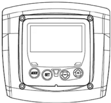
Figure 3: Aspect of the user interface
The user interface consists of a keypad with LCD display and POWER, COMMUNICATION and ALARM LEDs as seen in Figure 3.
The display shows the values and the statuses of the device, with indications on the functionality of the various parameters. The functions of the keys are summed up in Table 1.
 | | The MODE key allows you to move on to the next items in the same menu. Holding it down for at least 1 sec allows you to skip to previous menu item. |
| The SET key allows you to leave the current menu. |
| Decreases the current parameter (if it is an editable parameter). |
| Increases the current parameter (if it is an editable parameter). |
Table 2: Key functions
Holding down the “+” key or the “-” key allows the automatic increase/decrease of the parameter selected. After the “+” key or the “-” key has been held down for 3 seconds, the automatic increase/decrease speed increases.

When the + key or the - key is pressed the selected value is modified and saved immediately in the permanent memory (EEprom). If the machine is switched off, even accidentally, in this phase it does not cause the loss of the parameter that has just been set.
The SET key is only for leaving the current menu and is not necessary for saving the changes made. Only in particular cases described in the following paragraphs are some values updated by pressing "SET" or "MODE".
Warning leds
Power
White led. Lit with a fixed light when the machine is powered. Blinking when the machine is disabled.
- Alarm
Red led. Lit with a fixed light when the machine is blocked by an error.
The complete structure of all the menus and of all the items of which they are composed is shown in Table 4.
The desired menu can be accessed directly by pressing simultaneously the appropriate combination of keys for the required time (for example MODE SET to enter the Setpoint menu) and the various items in the menu are scrolled with the MODE key.
Table 3 shows the menus that can be reached with the combinations of keys.
ENGLISH
| MENU NAME | DIRECT ACCESS KEYS | HOLD-DOWN TIME |
| User |  | | On releasing the button |
| Monitor |  | | 2 Sec |
| Setpoint |  | | 2 Sec |
| Manual |  | | 3 Sec |
| Settings |  | | 3 Sec |
| Advanced settings |  | | 3 Sec |
| Reset factory values |  | | 2 Sec after switching on appliance |
| Reset |  | | 2 Sec |
Table 3: Access to the menus
| Main Menu | User Menu mode | Monitor Menu set-minus | Setpoint Menu mode-set | Manual Menu set-minus-plus | Settings menu mode-set-less | Advanced Settings menu mode-set-plus |
| MAIN (Main Page) | RS Revs per minute | CT Contrast | SP Setpoint pressure | RI Speed setting | RP Decrease pressure for restart | TB Block time for water lack. |
| VP Pressure | BK Back lighting | | VP Pressure | OD Type of plant | T2 Delay in switching off |
| VF Display of flow | TK Backlighting switch-on time | | VF Display of flow | MS Measuring system | GP Proportional gain |
| PO Power absorbed by pump | TE Dissipator temperature | | PO Power absorbed by the line | FY Enabling dispensed volume block | GI Integral gain |
| C1 Pump phase current | | | C1 Pump phase current | TY Enabling pumping time block | RM Maximum speed |
| HO On time counter | | | | FH Dispensed volume | AY Anticycling |
| HW Running time counter | | | | TH Pumping time | AE Anti-blocking |
| NR Number of starts | | | | | AF AntiFreeze |
| EN Energy countet | | | | | FW Firmware update |
| ES Saving | | | | | RF Ripristino fault & warning |
| FC Flow counter | | | | | |
| VE Information HW e SW | | | | | |
| FF Fault & Warning (Log) | | | | | |
Table 4: Menu structure
ENGLISH
When the system is switched on the main page is displayed. Various combinations of keys (see Sect. 4.1 Access to menus) allow access to the machine menus. The icon relative to the current menu appears at the top of the display.
The following always appear on the main page:
Status: operating status (e.g. standby, go, Fault)
Pressure: value in [bar] or [psi] depending on the set unit of measure
Power: value in [kW] of the power absorbed by the device
Fault indications
Warning indications
Specific icons
The error conditions are indicated in Table 9. The other displays are indicated in Table 5.
| Error or status conditions shown on the main page |
| Identifying code Description | |
| Motor running |
 | Motor stopped |
 | Motor status manually disabled |
| Presence of an error preventing operation of the electropump |
| EE Writing and reading the factory settings on EEprom |
 | Warning due to lack of supply voltage |
 | Priming |
Table 5: Status and error messages on the main page
The other menu pages vary with the associated functions and are described later by type of indication or setting. In every page of the menu, the plant pressure is always displayed at the bottom while the symbols at the top indicate the current menu.
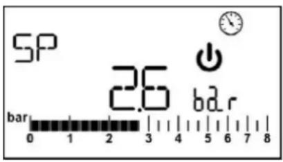
Figure 4: Display of a menu parameter
The pages showing the parameters may display: the numeric values and unit of measurement of the current item, values of other parameters linked to the setting of the current item see Figure 4.
In all the menu pages, except for those forming part of the user menu, a function is active which automatically restores the display of the main page 3 minutes after a key was last pressed.
4.3 Enabling and disabling the motor
In normal operating conditions, pressing and then releasing both the “+” and “-” keys causes the blocking/release of the motor (self-holding even after switching off). If an alarm is present, the operation described above resets the alarm. The motor disabled status is shown by the flashing white LED.
This command can be activated from any menu page except RF.
5. MEANING OF THE INDIVIDUAL PARAMETERS

The inverter makes the system work at constant pressure. This regulation is appreciated if the hydraulic plant downstream from the system is suitably sized. Plants made with pipes with too small a section introduce load losses that the equipment cannot compensate; the result is that the pressure is constant on the sensors but not on the utility

Plants that are excessively deformable can create the onset of oscillations; if this occurs, the problem can be solved by adjusting the control parameters "GP" and "GI" (see par 5.6.3 - GP: Proportional gain coefficient and 5.6.4 - GI: Integral gain coefficient)
ENGLISH
From the main menu, pressing the MODE key (or using the selection menu and pressing + o -), gives access to the USER MENU. In the menu the MODE key allows you to scroll through the various menu pages. The values shown are the following.
5.1.1 RS: Rotation speed display
Motor rotation speed in rpm.
5.1.2 VP: Pressure display
Plant pressure measured in [bar] or [psi] depending on the measuring system used.
5.1.3 VF: Flow display
Displays the instantaneous flow in [litres/min] or [gal/min] depending on the set measuring system.
5.1.4 PO: Absorbed power display
Power absorbed by the electropump in [kW].
If the maximum power absorbed is exceeded and power limitation is activated, the PO parameter symbol flashes.
5.1.5 C1: Phase current display
Motor phase current in [A].
If the maximum current supplied is temporarily exceeded, the C1 symbol flashes to indicate that an overcurrent is being delivered on the motor and if operation continues in these conditions, the overload protection will be activated.
5.1.6 HO: On time counter
Indicates the number of hours of electric supply to the device The total and partial On time counts are displayed alternately at 2 minute intervals. A "T" appears alongside the unit of measurement to display the total count and a "P" displays the partial count. The partial count can be reset by pressing the "-" key for at least 2 sec.
5.1.7 HW: Motor pump operating hours count
Indicates the number of hours of working of the pump. The total and partial time counts of the motor pump are displayed alternately at 2 minute intervals. A "T" appears alongside the unit of measurement to display the total count and a "P" displays the partial count. The partial count can be reset by pressing the "-" key for at least 2 sec.
5.1.8 NR: Number of start ups
Indicates the number of motor start ups.
5.1.9 EN: Energy absorbed counter
Indicates the energy absorbed from the mains in kW. The total and partial energy counts are displayed alternately at 2 minute intervals. A "T" appears alongside the unit of measurement to display the total count and a "P" displays the partial count. The partial count can be reset by pressing the "-" key for at least 2 sec.
5.1.10 ES: Saving
Indicates the percentage saving compared to the same pump controlled with an on/off system instead of inverter. The value calculated can be reset by pressing the “-” key for at least 2 sec.
5.1.11 FC: Pumped fluid volume count
Indicates the volume of fluid pumped by the system. The total and partial fluid volume counts are displayed alternately at 2 minute intervals. A "T" appears alongside the unit of measurement to display the total count and a "P" displays the partial count. The partial count can be reset by pressing the "-" key for at least 2 sec.
5.1.12 VE: Version display
Hardware and software version with which the appliance is equipped.
5.1.13 FF: FF: Fault log display
Chronological display of the faults that have occurred during system operation.
Under the symbol FF appear two numbers x/y indicating respectively the ault displayed and the total number of faults present; to the right of these numbers is an indication of the type of fault displayed.
The + and - keys scroll through the list of faults: pressing the - key goes back through the log and stops at the oldest fault present, pressing the + key goes forward in the log and stops at the most recent fault.
The faults are displayed in chronological order starting from the one that appeared farthest back in time x=1 to the most recent x=y. The maximum number of faults that can be shown is 64; when that number is reached, the log starts to overwrite the oldest ones.
This item on the menu displays the list of faults, but does not allow reset. The reset can be done only by means of the command from RF of the ADVANCED SETTINGS MENU.
The fault log cannot be deleted with a manual reset, by switching off the appliance, or by resetting the factory values, unless the procedure described above has been followed.
Keep the "SET" and "-" (minus) keys pressed simultaneously for 2 sec from the main menu to access the MONITOR MENU. In this menu, by pressing the MODE key, the following values are displayed in sequence.
ENGLISH
5.2.1 CT: Display contrast
Adjusts the display contrast
5.2.2 BK: Display brightness
Adjusts the backlighting of the display on a scale from 0 to 100.
5.2.3 TK: Backlight switch-on time
Sets the time that the backlight is lit since the last time a key was pressed.
Values allowed: '0' always off; from 20 sec to 10 min or 'always on'. With the backlight setting always ON, the display shows "ON". When the backlight is off, the first time any key is pressed has the sole effect of restoring the backlighting.
5.2.4 TE: Dissipator temperature display
From the main menu, hold down simultaneously the "MODE" and "SET" keys until "SP" appears on the display.
The + and – keys allow you respectively to increase and decrease the plant boosting pressure. Press SET to leave this menu and return to the main menu. The range of adjustment is 1-5 bar (14-80 psi).
5.3.1 SP: Setting the setpoint pressure
Pressure at which the system is pressurised

The pump restarting pressure is linked not only to the set pressure SP but also to RP. RP expresses the decrease in pressure, with respect to "SP" caused by the pump starting.
For example: SP = 3,0 [bar]; RP = 0,3 [bar];
During normal operation the system is pressurised at 3.0 [bar]. The electropump restarts when the pressure falls below 2,7[bar].

Setting a pressure (SP) that is too high for the pump performance may cause false water lack errors BL; in these cases lower the set pressure.
Attention: the setting of particular values of this parameter with relation to the system may help create situations of risk due to high water temperatures being reached inside the pump (see Warnings, Chap. 2).

In manual operation, the sum of the input pressure and the maximum pressure that can be supplied must not be greater than 6 bar.
From the main menu, hold down simultaneously the "SET" and "+" and "-" keys until the manual menu page appears. The menu allows you to view and modify various configuration parameters: the MODE key allows you to scroll through the menu pages, the + and - keys allow you respectively to increase and decrease the value of the parameter concerned. Press SET to leave this menu and return to the main menu.
Entering the manual menu by pressing the SET + - keys puts the machine into forced STOP condition. This function can be used to force the machine to stop.
In the main menu, irrespective of the parameter displayed, it is always possible to perform the following controls:
• Temporary starting of the electropump.
• Permanent pump start up.
- Modification of number of pump rotations in manual mode.
Pressing the MODE and + keys at the same time causes the pump to start at speed RI and this running status remains as long as the two keys are held down.
When the pump ON of pump OFF command is given, a communication appears on the display.
Starting the pump
Holding down the MODE - + keys simultaneously for 2 sec. causes the pump to start at speed RI. The running status remains until the SET key is pressed. The next time the SET key is pressed the pump leaves the manual menu.
When the pump ON of pump OFF command is given, a communication appears on the display.
In case of operation in this mode for more than 5' without the presence of hydraulic fluid, the machine stops, giving the PH alarm.
Once the PH error condition is no longer present, the alarm will be reset automatically only. The reset time is 15'; if the PH error occurs more than 6 times consecutively, the reset time increases to 1h. Once it has reset further to this error, the pump will remain in stop status until the user restarts it using the "MODE" "-" "+" keys.

Attention: the use of this operating mode may help create situations of risk due to high water temperatures being reached inside the pump (see Warnings, Chap. 2).
ENGLISH
5.4.1 RI: Speed setting
Sets the motor speed in rpm. Allows you to force the number of revolutions at a predetermined value.
If the rotations made differ from the rotation setting "RI", the number of rotations set and the number of rotations made are displayed alternately. When the number of rotations made is displayed, an "A" appears alongside the unit of measurement. Each time the "+" or "-" is pressed to modify the RI, the display automatically shows the number of rotations set.
5.4.2 VP: Pressure display
Plant pressure measured in [bar] or [psi] depending on the measuring system used.
5.4.3 VF: Flow display
Displays the flow in the chosen unit of measure. The measuring unit may be [l/min] o [gal/min] vedi par. 5.5.3 - MS: Measuring system
5.4.4 PO: Absorbed power display
Power absorbed by the electropump in [kW].
If the maximum power absorbed is exceeded and power limitation is activated, the PO parameter symbol flashes.
5.4.5 C1: Phase current display
Motor phase current in [A].
If the maximum current supplied is exceeded temporarily, the C1 symbol flashes to indicate that the motor overload protection is being activated and if operation continues in this condition, the overload protection is activated.
From the main menu, keep the "MODE" & "SET" & "-" keys pressed simultaneously until the first parameter of the settings menu appears on the display.
The menu allows you to view and modify various configuration parameters: the MODE key allows you to scroll through the menu pages, the + and - keys allow you respectively to increase and decrease the value of the parameter concerned. Press SET to leave this menu and return to the main menu.
5.5.1 RP: Setting the pressure fall to restart
Expresses the fall in pressure with respect to the SP value which causes restarting of the pump.
For example if the setpoint pressure is 3.0 [bar] and RP è 0.5 [bar] the pump will restart at 2.5 [bar]. RP can be set from a minimum of 0.1 to a maximum of 1,5 [bar]. In particular conditions (for example in the case of a setpoint lower than the RP) it may be limited automatically.

Attention: the setting of particular values of this parameter with relation to the system may help create situations of risk due to high water temperatures being reached inside the pump (see Warnings, Chap. 2).
5.5.2 OD: Type of plant
Possible values "R" and "E" referring to a rigid system and an elastic system.
The device leaves the factory with mode "R" suitable for the majority of systems. In the presence of swings in pressure that cannot be stabilised by adjusting the parameters GI and GP, change to mode 2
IMPORTANT: The regulating parameters GP and GI also change in the two configurations. In addition the GP and GI values set in mode 1 are stored in a different memory from the GP and GI values set in mode 2. So, for example, when passing to mode 2, the GB value of mode 1 is replaced by the GB value of mode 2 but it is kept and will reappear again when returning to mode 1. The same value shown on the display has a different weight in one mode or in the other because the control algorithm is different.
5.5.3 MS: Measuring system
Set the measuring system, choosing between metric and imperial units. The quantities displayed are shown in Table 6.
NOTE: The flow in English-speaking units (gal/min) is indicated adopting a conversion factor of 1 gal = 4.0 litres, corresponding to the metric gallon.
| Units of measurement displayed |
| Quantity Metric units Imperial units | |
| Pressure | bar | psi |
| Temperature | °C | °F |
| Flow rate lpm gpm | | |
Table 6: Measuring system
Acronyms lpm and gpm indicate litres/min and gallons/min, respectively.
5.5.4 FY: Enabling dispensed volume block
Enables the block function on the fluid volume dispensed FH.
ENGLISH
5.5.5 TY: Enabling pumping time block
Enables the block function on the pumping time TH.
5.5.6 TY: FH: Dispensed volume
Sets the fluid volume reached at which the pumping is stopped. If the function is enabled (parameter FY), see Sect. 5.5.4, the inverter measures the fluid volume dispensed and when the FH volume set by the user is reached, pumping is disabled. The system remains in block until it is reset manually. Reset can be done from any page of the menu by pressing the "+" and "-" keys simultaneously and then releasing them. The count and block status are saved in memory and will therefore be retained even after the system is switched off and then switched on again. When the dispensed volume block is activated, the relative count is displayed in the main page and it decreases from the preset value to 0. When the count reaches zero, the system stops and the count starts flashing. The count starts the moment the FY is enabled or the moment of the last FH setting or from the moment the block was reset by pressing the "+" and "-" keys. The block generated is not recorded in the fault queue. FH may be set between 10 litres (2.5 gal) and 32000 litres (8000 gal).
5.5.7 TH: Pumping time
Sets the pumping time after which the pumping stops. If the function is enabled (parameter TY), see Sect. 5.4.5, the inverter measures the pump operating time and when the TH value set by the user is reached, pumping is disabled. The system remains in block until it is reset manually. Reset can be done from any page of the menu by pressing the "+" and "-" keys simultaneously and then releasing them. The count and block status are saved in memory and will therefore be retained even after the system is switched off and then switched on again. When the pumping time block is activated, the relative count is displayed in the main page and it decreases from the preset value to 0. When the count reaches zero, the system stops and the count starts flashing. The count starts the moment the TY is enabled or the moment of the last TH setting or from the moment the block was reset by pressing the "+" and "-" keys and is counted only if pumping is active. The block generated is not recorded in the fault queue. TH may be set between 10 sec and 9h.
Advanced settings to be made only by skilled personnel or under the direct control of the service network.
From the main menu, hold down simultaneously the "MODE" and "SET" keys until "SP" appears on the display (or use the selection menu pressing + or -). The menu allows you to view and modify various configuration parameters: the MODE key allows you to scroll through the menu pages, the + and - keys allow you respectively to increase and decrease the value of the parameter concerned. Press SET to leave this menu and return to the main menu.
5.6.1 TB: Water lack blockage time
Setting the reaction time of the water lack blockage allows you to select the time (in seconds) taken by the device to indicate the lack of water.
The variation of this parameter may be useful if there is known to be a delay between the moment the motor is switched on and the moment it actually begins to deliver. One example may be a plant where the suction pipe is particularly long and there are some slight leaks. In this case the pipe in question may be discharged and, even though water is not lacking, the electropump will take a certain time to reload, supply the flow and put the plant under pressure.
5.6.2 T2: Delay in switching off
Sets the delay with which the inverter must switch off after switch-off conditions have been reached: plant under pressure and flow rate lower than the minimum flow.
T2 can be set between 2 and 120 s. The factory setting is 10 s.

Attention: the setting of particular values of this parameter with relation to the system may help create situations of risk due to high water temperatures being reached inside the pump (see Warnings, Chap. 2).
5.6.3 GP: Proportional gain coefficient
Generally the proportional term must be increased for systems characterised by elasticity (for example with PVC pipes) and lowered in rigid systems (for example with iron pipes).
To keep the pressure in the system constant, the inverter performs a type PI control on the measured pressure error. Depending on this error the inverter calculates the power to be supplied to the motor. The behaviour of this control depends on the set GP and GI parameters. To cope with the different behaviour of the various types of hydraulic plants where the system can work, the inverter allows the selection of parameters different from those set by the factory. For nearly all plants the factory-set GP and GI parameters are optimal. However, should any problems occur in adjustment, these settings may be varied.

Attention: the setting of particular values of this parameter with relation to the system may help create situations of risk due to high water temperatures being reached inside the pump (see Warnings, Chap. 2).
5.6.4 GI: Integral gain coefficient
In the presence of large falls in pressure due to a sudden increase of the flow or a slow response of the system, increase the value of GI. Instead, if there are swings in pressure around the setpoint value, decrease the value of GI.
ENGLISH

Attention: the setting of particular values of this parameter with relation to the system may help create situations of risk due to high water temperatures being reached inside the pump (see Warnings, Chap. 2).
IMPORTANT: To obtain satisfactory pressure adjustments, you generally have to adjust both GP and GI.
5.6.5 RM: Maximum speed
Sets a maximum limit on the number of pump revolutions.
5.6.6 AY: Anti Cycling
As described in paragraph 9, this function is for avoiding frequent switching on and off in the case of leaks in the system. The function can be enabled in 2 different modes, normal and smart. In normal mode the electronic control blocks the motor after N identical start/stop cycles. In smart mode it acts on the parameter RP to reduce the negative effects due to leaks. If set on "Disable", the function does not intervene.
5.6.7 AE: Enabling the anti-block function
This function is for avoiding mechanical blocks in the case of long inactivity; it acts by periodically rotating the pump.
When the function is enabled, every 23 hours the pump performs an unblocking cycle lasting 1 min.
5.6.8 AF: Enabling the anti-freeze function
If this function is enabled the pump is automatically rotated when the temperature reaches values close to freezing point, in order to avoid breakages of the pump.
5.7 RF: Fault and warning reset
Holding down the - key for at least 2 seconds deletes the history of faults and warnings. The number of faults present in the log is indicated under the symbol RF (max 64).
The log can be viewed from the MONITOR menu on page FF
6. PROTECTION SYSTEMS
The device is equipped with protection systems to preserve the pump, the motor, the supply line and the inverter. If one or more protections trip, the one with the highest priority is immediately notified on the display. Depending on the type of error the motor may stop, but when normal conditions are restored the error status may be cancelled immediately or only after a certain time, following an automatic reset.
In the case of blockage due to water lack (BL), blockage due to motor overload (OC), blockage due to direct short circuit between the motor phases (SC), you can try to exit the error conditions manually by simultaneously pressing and releasing the + and - keys. If the error condition remains, you must take steps to eliminate the cause of the fault.
In the event of blocking due to one of the internal errors E18, E19, E20, E21 it is necessary to wait 15 minutes with the machine powered until the blocked status is automatically reset.
| Alarm in the fault log |
| Display indication | Description |
| PD Irregular switching off | |
| FA Problems in the cooling system | |
Table 7: Alarms
| Blockage conditions |
| Display indication Description |
| PH | Block due to excessive operating time without hydraulic flow |
| BL | Blockage due to water lack |
| BP1 | Blockage due to reading error on the delivery pressure sensor |
| PB | Blockage due to supply voltage outside specifications |
| OT | Blockage due to overheating of the power stages |
| OC | Blockage due to motor overload |
| SC | Blockage due to short circuit between the motor phases |
| ESC | Blockage due to short circuit to earth |
| HL | Hot liquid |
| NC | Blockage due to motor disconnected |
| Ei | Blockage due to i-th internal error |
| Vi | Blockage due to i-th internal voltage out of tolerance |
| EY | Block for cyclicality abnormal detected on the system |
Table 8: Indications of blockages
6.1 Description of blockages
6.1.1 "BL" Anti Dry-Run (Protection against dry running)
In the case of lack of water the pump is stopped automatically after the time TB. This is indicated by the red "Alarm" led and by the letters "BL" on the display. After having restored the correct flow of water you can try to leave the protective block manually by pressing the "+" and "-" keys simultaneously and then releasing them. If the alarm status remains, or if
ENGLISH
the user does not intervene by restoring the flow of water and resetting the pump, the automatic restart will try to restart the pump.

If the parameter SP is not correctly set, the protection against water lack may not work correctly.
6.1.2 Anti-Cycling (Protection against continuous cycles without utility request))
If there are leaks in the delivery section of the plant, the system starts and stops cyclically even if no water is intentionally being drawn: even just a slight leak (a few ml) can cause a fall in pressure which in turn starts the electropump.
The electronic control of the system is able to detect the presence of the leak, based on its recurrence.
The Anti-Cycling function can be excluded or activated in Basic or Smart mode (par 5.6.6).
In Basic mode, once the condition of recurrence is detected the pump stops and remains waiting to be manually reset. This condition is communicated to the user by the lighting of the red "Alarm" led and the appearance of the word "ANTICYCLING" on the display. After the leak has been removed, you can manually force restart by simultaneously pressing and releasing the "+" and "-" keys.
In Smart mode, once the leak condition is detected, the parameter RP is increased to decrease the number of starts over time.
6.1.3 Anti-Freeze (Protection against freezing of water in the system)
The change of state of water from liquid to solid involves an increase in volume. It is therefore essential to ensure that the system does not remain full of water with temperatures close to freezing point, to avoid breakages of the system. This is the reason why it is recommended to empty any electropump that is going to remain unused during the winter. However, this system has a protection that prevents ice formation inside by activating the electropump when the temperature falls to values close to freezing point. In this way the water inside is heated and freezing prevented.

The Anti-Freeze protection works only if the system is regularly fed: with the plug disconnected or in the absence of current the protection cannot work.
However, it is advised not to leave the system full during long periods of inactivity: drain the system accurately through the drainage cap and put it away in a sheltered place.
6.1.4 "BP1" Blockage due to fault of the delivery pressure sensor (system pressurisation)
If the device detects a fault in the delivery pressure sensor the pump remains blocked and the error signal "BP1" is given. This status begins as soon as the problem is detected and ends automatically when correct conditions have been restored.
6.1.5 "PB" Blockage due to supply voltage outside specifications
This occurs when the allowed line voltage at the supply terminal assumes values outside the specifications. It is reset only automatically when the voltage at the terminal returns within the allowed values.
6.1.6 "SC" Blockage due to short circuit between the motor phases
The device is provided with protection against the direct short circuit which may occur between the motor phases. When this blockage is indicated you can attempt to restore operation by simultaneously holding down the + and - keys, but this will not have any effect until 10 seconds have passed since the moment the short circuit occurred.
6.2 Manual reset of error conditions
In error status, the user can cancel the error by forcing a new attempt, pressing and then releasing the + and - keys.
6.3 Self-reset of error conditions
For some malfunctions and blockage conditions, the system attempts automatic self-reset.
"BL" Blockage due to water lack
"PB" Blockage due to line voltage outside specifications
"OT" Blockage due to overheating of the power stages
"OC" Blockage due to motor overload
"BP" Blockage due to fault of the pressure sensor
For example, if the system is blocked due to water lack, the device automatically starts a test procedure to check whether the machine is really left definitively and permanently dry. If during the sequence of operations an attempted reset is successful (for example, the water comes back), the procedure is interrupted and normal operation is resumed.
Table 9 shows the sequences of the operations performed by the device for the different types of blockage.
| Automatic resets of error conditions |
| Display indication | Description | Automatic reset sequence |
| BL | Blockage due to water lack | - One attempt every 10 minutes for a total of 6 attempts.- One attempt every hour for a total of 24 attempts- One attempt every 24 hours for a total of 30 attempts. |
ENGLISH
| PB | Blockage due to line voltage outside specifications | It is reset when it returns to a specific voltage. |
| OT | Blockage due to overheating of the power stages | It is reset when the temperature of the power stages returns within the specifications. |
| OC | Blockage due to motor overload | - One attempt every 10 minutes for a total of 6 attempts.- One attempt every hour for a total of 24 attempts.- One attempt every 24 hours for a total of 30 attempts. |
Table 9: Self-reset of blockages
7. RESET AND FACTORY SETTINGS
7.1 General system reset
To reset the system, hold down the 4 keys simultaneously for 2 sec. This operation is the same as disconnecting the power, waiting for it to close down completely and supplying power again. The reset does not delete the settings saved by the user.
7.2 Factory settings
The device leaves the factory with a series of preset parameters which may be changed according to the user's requirements. Each change of the settings is automatically saved in the memory and, if desired, it is always possible to restore the factory conditions (see Restoring the factory settings par par 7.3 - Restoring the factory settings).
7.3 Restoring the factory settings
To restore the factory values, switch off the device, wait until the display has switched off completely, press and hold down the "SET" and "+" keys and turn on the power; release the two keys only when the letters "EE" appear.
This restores the factory settings (a message and a rereading on EEPROM of the factory settings permanently saved in the FLASH memory).
Once all the parameters have been set, the device returns to normal operation.
NOTE: Once the factory values have been restored it will be necessary to reset all the parameters that characterise the system (gains, setpoint pressure, etc.) as at the first installation.
| Factory settings |
| Identifying code | Description | Value Installation | Memo |
| CT | Contrast 15 | | |
| BK | Backlighting 85 | | |
| TK | T. backlighting On 2 min | | |
| SP Setpoint pressure [bar] 3,0 | | |
| RI | Revs per minute in manual mode [rpm] | 4000 | |
| OD Type of plant R (Rigid) | | |
| RP | Pressure decrease to restart [bar] | 0,5 | |
| MS Measuring system I (International) | | |
| FY FH limit enabling OFF | | |
| TY | TH limit enabling | OFF | |
| FH | Limit for pumped volume | 100 [l]25 [gal] | |
| TH | Limit for pumping time | 10 min | |
| TB | Blockage time for water lack [s] | 10 | |
| T2 | Delay in switching off [s] | 10 | |
| GP | Proportional gain coefficient | 0,5 | |
| GI | Integral gain coefficient | 1,2 | |
| RM | Maximum speed [rpm] | 7000 | |
| AY | Anticycling Function | SMART | |
| AE | Anti-blocking function | ON(Enable) | |
| AF | Antifreeze | ON(Enable) | |
Table 10: Factory settings
ENGLISH
8. PARTICULAR INSTALLATIONS
8.1 - e18
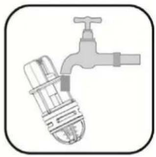
The product is made and supplied with the capacity of being self-priming. With reference to par. 4, the system is able to prime and therefore operate in whatever installation configuration chosen: below head or above head. However there are cases in which the self-priming capacity is not necessary, or areas where it is forbidden to use self-priming pumps. During priming the pump obliges part of the water already under pressure to return to the suction part until a pressure value is reached at delivery whereby the system can be considered primed. At this point the recirculating channel closes automatically. This phase is repeated each time the pump is switched on, even already primed, until the same pressure value that closes the recirculating channel is reached (about 1 bar).
When the water arrives at the system intake already under pressure or when the installation is always below head, it is possible (and mandatory where local regulations require it) to force the closure of the recirculating pipe, losing the self-priming capacity. This obtains the advantage of eliminating the clicking noise of the pipe shutter each time the system is switched on.
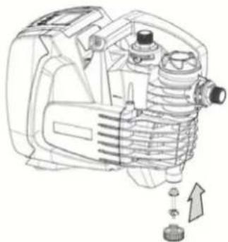
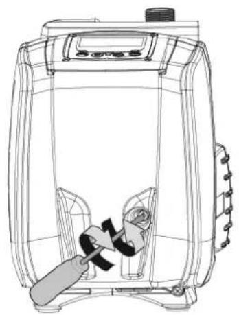
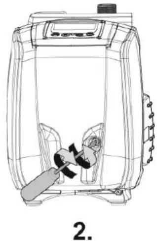
To force closure of the self-priming pipe, proceed as follows:
- Disconnect the power supply;
- empty the system;
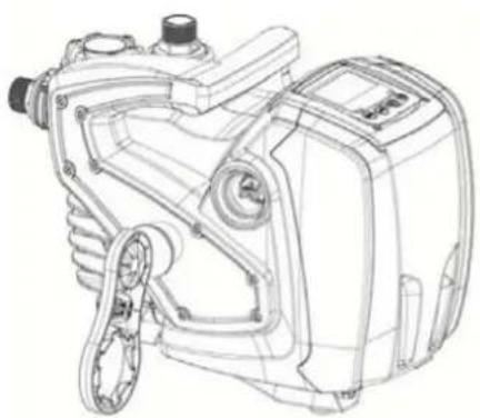
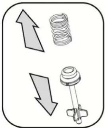
- remove the drainage cap, taking care to make sure the O-Ring does not fall (Fig. 5) (Fig.5);
- with the aid of pliers take the shutter out of its seat. The shutter will be extracted together with the O-Ring and the metal spring with which it is assembled;
- remove the spring from the shutter; insert the shutter in its seat again with the respective O-Ring (side with gasket towards the inside of the pump, stem with cross-shaped fins towards the outside);
- screw on the cap after having positioned the metal spring in side so that it is compressed between the cap itself and the with cross-shaped fins of the shutter stem. When repositioning the cap ensure that the respective O-Ring is always correctly in its seat;
- fill the pump, connect the power supply, start the system.

If the system is installed on a plant, it is advisable to force closure of the self-priming duct before use the first time, or, in any case, before connecting the system to the plant. With the electric power supply disconnected, follow points 3. to 7. listed above (Sect. 8.1).
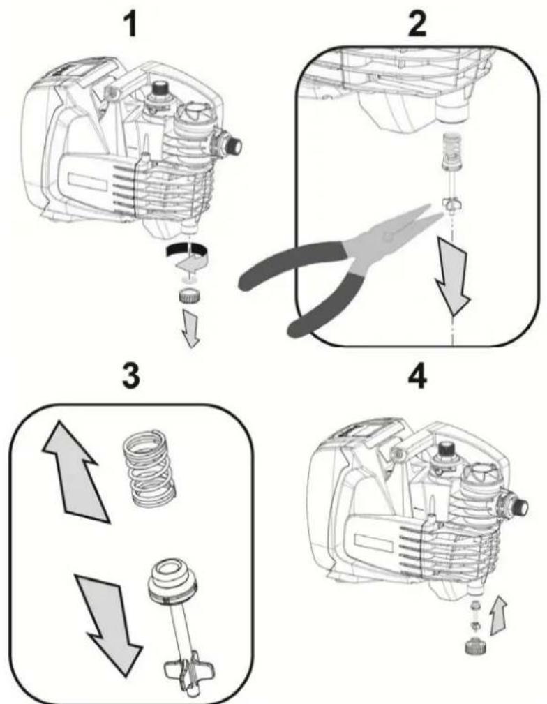
Figure 5
ENGLISH
9. MAINTENANCE
Disconnect the power supply before starting any work on the system.
The only routine maintenance operation required involves cleaning the built-in filter (section 9.2).
Instructions are also given for carrying out extraordinary maintenance operations that may be necessary in special cases (e.g. draining the system before storing it during shutdowns).
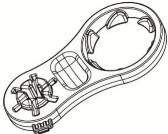
Together with the product, DAB supplies an accessory for removing the filler and breather caps.
natural_image
Technical line drawing of a mechanical component with internal gears and housing (no text or symbols)
Figure 6
9.2 Cleaning the Built-in Filter
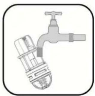
For correct working of the system and achieving the declared performance, clogging of the filter must be prevented. Check the filter cartridge periodically through the transparent cover and, if necessary, clean it as described below.
- disconnect the electric supply and wait for 10 minutes;
- if the system is installed with positive suction head, close the On/Off valve at the suction end;
- remove the filler cap by unscrewing it manually or use the tool included in the supply;
- remove the cartridge without rotating it. the relative filter cup-support is also released;
- empty the cup and wash the cartridge under running water;
- refit the cartridge back in place taking care to make sure it fits in the cup by means of a bayonet coupling;
- close the filler cap so that it comes to a mechanical stop.
If the system is to be reused, and not stored away, restore the pump suction and repeat the filling (Sect.2.2) and priming (Sect.3.3) operations, preferably before point 7. in case of suction lift installation.
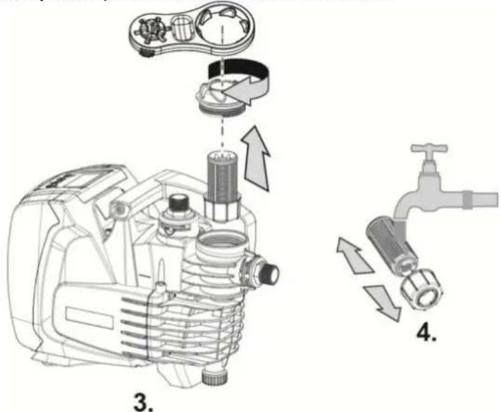
Figure 7
ENGLISH
9.2 Emptying the system
If you want to drain the water out of the system, proceed as follows:
- disconnect the electric supply and wait for 10 minutes;
-
if the system is installed on a plant, cut off the suction duct at the point nearest to the system (it is advisable to have an On/Off valve immediately upline of the system) so that the entire suction system is also not discharged;
-
if the system is installed on a plant, open the nearest delivery tap to discharge pressure to the plant and drain it as much as possible;
-
If the system is installed on a plant, if an On/Off valve is present immediately downline (it is always advisable to have one), close this to prevent the quantity of water from flowing back to the plant between the system and the first tap open;
-
disconnect the pump from the plant;
-
remove the drainage cap (4-Fig.1) and drain out the water inside;
-
refit the drainage cap back in place, taking care to make sure the O-Ring is positioned properly inside it;
-
the water trapped in the delivery system downline of the non-return plant integrated in the system can flow back only the moment the system is disconnected.

Though essentially drained, the system is unable to expel all the water that it contains.
During handling of the system after emptying it, some small amounts of water may probably leak out from the system.
It is always advisable to use a three-piece connector at the suction as well as delivery to be able to execute point 5 easily.
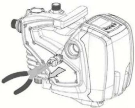
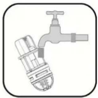
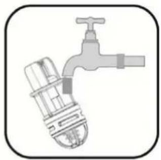
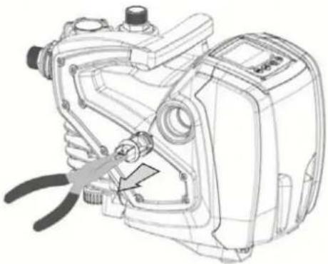
9.3 Non-return valve
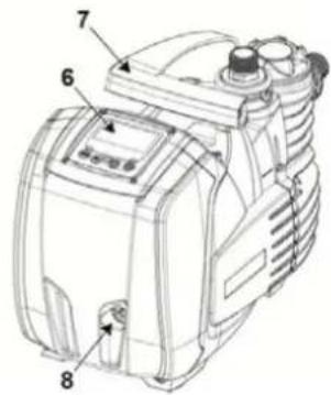
The system has an integrated non-return valve which is necessary for correct operation. The presence of solid bodies or sand in the water could cause malfunctioning of the valve and therefore of the system. Although the use of clear water and the presence of a filter at the inlet is recommended, if the non-return valve is seen to operate abnormally, it can be removed from the system and cleaned and/or replaced by proceeding as follows:
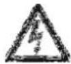
- drain the system by following points 1 to 6. of Section 9.2;
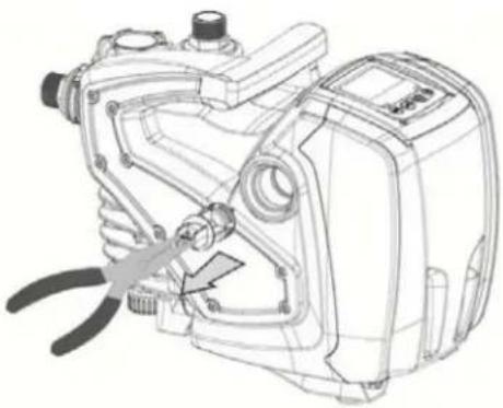
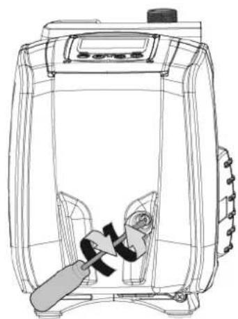
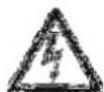
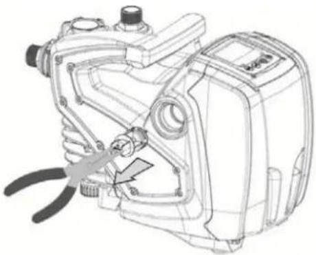
- using a screwdriver or special accessory meant for the purpose remove the breather cap to be able to access the non-return valve (Fig. 8);
- using pliers, extract the cartridge of the non-return valve without rotating it, gripping it by the jumper provided for the purpose (Fig.8): the operation may require a certain effort;
- clean the valve under running water, ensure that it is not damaged and replace it if necessary;
- put the complete cartridge back in its seat: the operation requires the force necessary to compress the 2 O-Rings (Fig.8);
- screw the breather cap to fit flush: if the cartridge has not been pushed correctly into place, screw the cap in to position it completely (Fig. 8).

To remove the non-return valve, the delivery piping section should be drained completely.
natural_image
Technical line drawing of a mechanical device with no visible text or symbols
2.
natural_image
Technical line drawing of a mechanical device with pliers and adjustment knobs (no text or symbols)
3.
natural_image
Illustration of a faucet with a valve and handle (no text or symbols)
- Figure 8
ENGLISH

Should one or more O-rings be lost or damaged during maintenance operations on the non-return valve, they must be replaced. Otherwise the system might not work correctly.
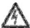
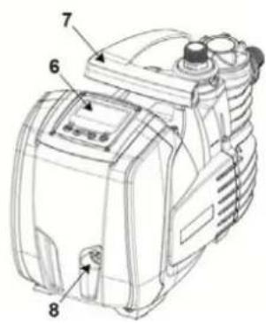
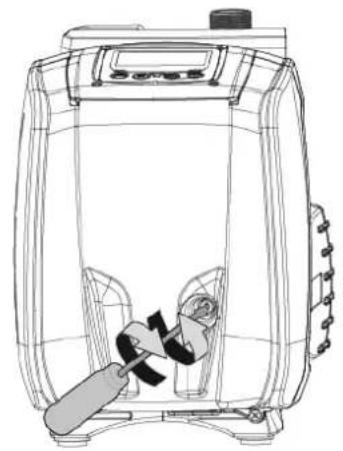
9.4 Motor shaft
The electronic control of the system ensures smooth starts so as to avoid excessive stress on the mechanical parts and thus prolong the life of the product. In exceptional cases this characteristic could cause problems in starting the pump: after a period of inactivity, perhaps with the system drained, the salts dissolved in the water could have settled and formed calcification between the moving part (motor shaft) and the fixed part of the pump, thus increasing the resistance on starting. In this case it may be sufficient to help the motor shaft by hand to detach itself from the calcifications. In this system the operation is possible because access to the motor shaft from outside is guaranteed and a groove is provided at the end of the shaft. Proceed as follows:
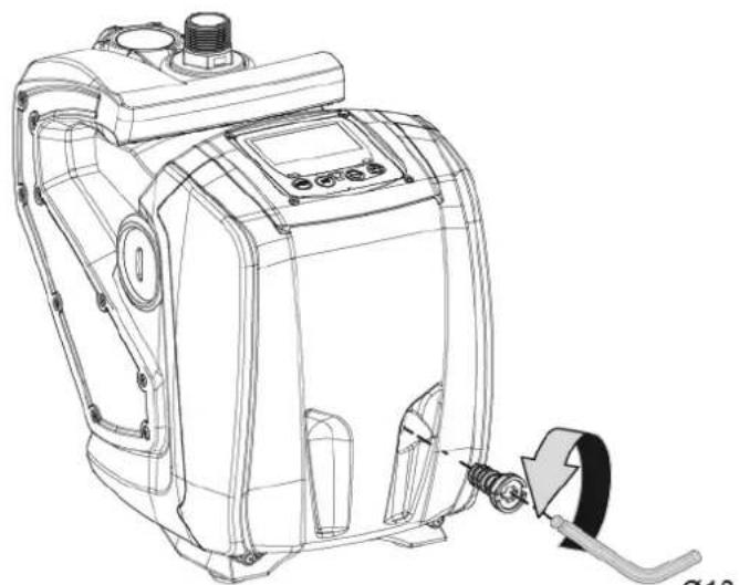
- using a 10mm hexagonal key, remove the motor shaft access cap (fig.9);
- insert a straight tip screwdriver in the groove on the motor shaft and manoeuvre, turning in 2 directions (fig. 9);
- if it is turning freely the system can be started, after having replaced the cap and cover that have been removed;
- if rotation is blocked and it cannot be removed by hand, call the assistance service.
natural_image
Technical line drawing of a mechanical device with a screw and adjustment knob (no text or symbols)
1.
natural_image
Line drawing of a portable energy organizer with a handle and control panel (no text or symbols)
- Figure 9
10. TROUBLESHOOTING
Before starting to look for faults it is necessary to disconnect the power supply to the pump (take the plug out of the socket)
| Fault | LED | Probable | Causes | Remedies |
| The pump does not start. Red: offWhite: offBlue: off | No electric power. Check whether there is voltage in the socket and insert the plug again. |
| The pump does not start. Red: onWhite: onBlue: off | Shaft blocked. See paragraph 9.4 (motor shaft maintenance). |
| The pump does not start. Red: offWhite: onBlue: off | Utility at a level higher than the system restarting pressure level (par. 3.2). | Increase the system restarting pressure level by increasing SP or decreasing RP. |
| The pump does not stop. Red: offWhite: onBlue: off | 1. Leak in the system.2. Impeller or hydraulic part clogged.3. Air getting into the suction pipe.4. Faulty flow sensor. | 1. Check the system, find and eliminate the leak.2. Dismantle the system and remove the obstructions (assistance service).3. Check the suction pipe, |
ENGLISH
| | | find and eliminate the cause of air getting in.4. Contact the assistance centre. |
| Insufficient delivery. Red: off | White: onBlue: off | 1. Suction depth too high.2. Suction pipe clogged or diameter insufficient.3. Impeller or hydraulic part clogged. | 1. As the suction depth increases the hydraulic performance of the product decreases. Check whether the suction depth can be reduced. Use a suction pipe with a larger diameter (but never smaller than 1").2. Check the suction pipe, find the cause of choking (obstruction, dry bend, counterslope..) and remove it.3. Dismantle the system and remove the obstructions (assistance service). |
| The pump starts without utility request. | Red: offWhite: onBlue: off | 1. Leak in the system.2. Faulty non-return valve. | 1. Check the system, find and eliminate the leak.2. Service the non-return valve as described in par. 9.3. |
| The water pressure wh turning on the utility is n immediate (*). | Red: offWhite: onBlue: off | Expansion vessel empty (insufficient air pressure) or has broken diaphragm. | Check the air pressure in the expansion vessel. If water is found to flow out during the inspection, it means the tank is brokenOtherwise restore the air pressure according to equation P= SetPoint-1bar. |
| When the utility is turned on the flow falls to zero before the pump starts (*). | Red: offWhite: onBlue: off | Air pressure in the expansion vessel higher than the system starting pressure. | Set the expansion tank pressure or configure the SP and/or RP parameters in such a manner as to satisfy the equation P= SetPoint-1bar. |
| The display shows BL. Red: on White: on Blue: off | 1. No water.2. Pump not primed.3. Setpoint not reachable with the set RM value. | 1-2. Prime the pump and check whether there is air in the pipe. Check whether the suction or any filters are blocked.3. Set a RM value that allows the setpoint to be reached. |
| The display shows BP1. Red: on White: on Blue: off | 1. Faulty pressure sensor. 1. Contact the assistance centre. |
| The display shows OC. | Red: on White: on Blue: off | 1. Excessive absorption.2. Pump blocked. | 1. Fluid too dense. Do not use the pump for fluids other than water.2. Contact the assistance centre. |
| The display shows PB. | Red: on White: on Blue: off | 1. Supply voltage too low.2. Excessive drop in voltage on the line. | 1. Check the presence of the correct supply voltage.2. Check the section of the power supply cables. |
(*) In case of installation of an expansion tank.
ENGLISH
11. DISPOSAL
This product or its parts must be disposed of in an environment-friendly manner and in compliance with the local regulations concerning the environment; use public or private local waste collection systems.
12. GUARANTEE
Any modification made without prior authorisation relieves the manufacturer of all responsibility. All the spare parts used in repairs must be authentic and all accessories must be authorised by the manufacturer, in order to ensure maximum safety of the machines and of the systems in which they may be installed.
This product is covered by a legal guarantee (in the European Community for 24 months from date of purchase) against all defects that can be assigned to manufacturing faults or to the material used.
The product under guarantee may, at discretion, either be replaced with one in perfect working order or replaced free of charge if the following conditions are observed:
- the product has been used correctly in compliance with the instructions and not attempt has been made to repair it by the buyer or by third parties.
- the product has been consigned to the outlet where it was purchased, attaching a document as proof of purchase (invoice or cash register receipt) and a brief description of the problem found.
The impeller and parts subject to wear are not covered by the guarantee. Intervention under guarantee does not extend the initial guarantee period in any way.
ITALIANO
INDICE
1. GENERALITÀ 24
1.1 Inverter Integrato
natural_image
Line drawing of a control panel with buttons labeled MODE, SET, and directional indicators (no text or symbols beyond basic labels)
5.6.6 AY: Anti Cycling
natural_image
Technical line drawing of a mechanical device with internal components and a downward arrow indicating motion (no text or symbols)
2

natural_image
Illustration of a mechanical assembly with a tool and a downward arrow indicating a process (no text or symbols)
3
natural_image
Diagram showing three mechanical components: a spring, a valve, and a cross-shaped connector with directional arrows (no text or labels)
4
natural_image
Technical line drawing of an air compressor assembly with no visible text or symbols
Figura 5
9. MANUTENZIONE
natural_image
Technical line drawing of a mechanical device with internal components (no text or symbols)
Figura 6
ITALIANO
Figura 7
natural_image
Technical line drawing of a mechanical device with gears and housing (no text or symbols)
2.
natural_image
Technical line drawing of a mechanical device with pliers and adjustment knobs (no text or symbols)
3.
natural_image
Illustration of a faucet with a valve and handle, no text or symbols present
- Figura 8

natural_image
Technical line drawing of a mechanical device with a cable and adjustment knob (no text or symbols)
1.
natural_image
Line drawing of a portable energy organizer with a handle and control panel (no text or symbols)
- Figura 9
1. ALLGEMEINES......46
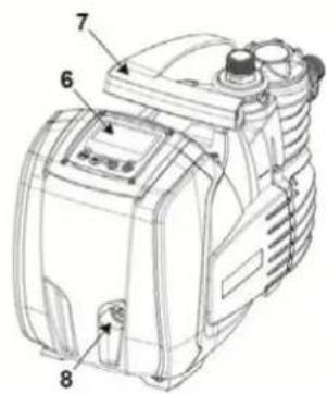
Abbildung 1
2.1 Hydraulikanschlüsse
natural_image
Line drawing of a control panel with buttons labeled MODE, SET, and directional arrows (no text or symbols beyond basic labels)
5.6.6 AY: Anti Cycling
natural_image
Technical line drawing of a mechanical device with internal components (no text or symbols)
Abbildung 6
natural_image
Technical line drawing of a mechanical device with no visible text or symbols
2.
natural_image
Technical line drawing of a mechanical device with a tool inserted, showing no text or symbols.
3.
natural_image
Illustration of a faucet with a water tap and pipe (no text or symbols)
4.
Abbildung 8

natural_image
Technical line drawing of a mechanical device with a cable and connector, labeled '1.' (no text or symbols on the diagram itself)
natural_image
Line drawing of a portable air purifier with a handle and internal components (no text or symbols)
Abbildung 9
10. PROBLEMLÖSUNG
1.1 Inverter integré
natural_image
Line drawing of a control panel with buttons labeled MODE, SET, and directional indicators (no text or symbols beyond basic labels)
5.6.6 AY: Anti Cycling
natural_image
Line drawing of a hand tool with internal components, labeled 'FRANÇAIS' (no other text or symbols)
Fig. 6
natural_image
Technical line drawing of an engine component with attached parts, showing internal components and assembly (no text or labels)
Fig. 7
natural_image
Technical line drawing of a mechanical device with no visible text or symbols
2.
natural_image
Technical line drawing of a mechanical device with a tool inserted, showing internal components and no visible text or symbols.
3.
natural_image
Illustration of a faucet with a water tap and pipe (no text or symbols)
- Fig. 8

natural_image
Technical line drawing of a mechanical device with a screw and adjustment knob (no text or symbols)
1.
natural_image
Line drawing of a portable air conditioner unit with a handle and control panel (no text or symbols)
- Fig. 9
10. RÉSOLUTION DES PROBLÈMES
1.1 Inverter integrado
natural_image
Line drawing of a portable electronic device front panel with buttons (MODE, SET, +) and no visible text or symbols
5.6.6 AY: Anti Cycling
natural_image
Technical line drawing of a mechanical device with internal components (no text or symbols)
Figura 6
ESPAÑOL
Figura 7
natural_image
Technical line drawing of a mechanical device with gears and housing (no text or symbols)
2.
natural_image
Technical line drawing of a mechanical device with a pliers inserted, no visible text or symbols
3.
natural_image
Illustration of a faucet with a water tap and pipe (no text or symbols)
- Figura 8

natural_image
Technical line drawing of a mechanical device with a cable and connector (no text or symbols)
1.

natural_image
Line drawing of a portable electric heater with a handle and control panel (no text or symbols)
- Figura 9

1.1 Vestavěný měnič
natural_image
Line drawing of a portable industrial control panel with buttons and display screen (no text or symbols)
5.6.6 AY: Anticycling
natural_image
Technical line drawing of a mechanical device with internal components and a downward arrow indicating motion (no text or symbols)
2

natural_image
Illustration of a mechanical assembly with a tool and a downward arrow indicating a process (no text or symbols)
3
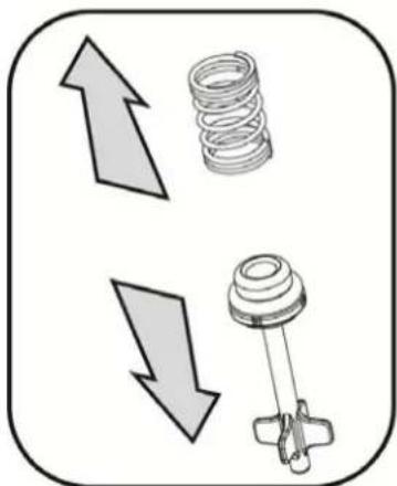
natural_image
Diagram showing three mechanical components: a spring, a valve, and a plunger, with directional arrows indicating movement (no text or labels)
4

natural_image
Technical line drawing of an industrial engine with internal components and a directional arrow indicating motion (no text or symbols)
Obr. 5
9. ÚDRŽBA

natural_image
Technical line drawing of a mechanical device with internal components (no text or symbols)
Obr. 6
ČESKY
natural_image
Technical line drawing of a mechanical device with no visible text or symbols
2.
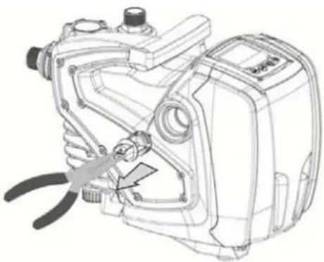
natural_image
Technical line drawing of a mechanical device with a tool inserted, showing internal components and mounting features (no text or symbols)
3.
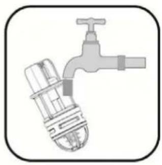
natural_image
Illustration of a faucet with a water tap and pipe (no text or symbols)
- Obr. 8

natural_image
Technical line drawing of a mechanical device with a cable and connector (no text or symbols)
1.

natural_image
Line drawing of a portable electric heater with a handle and control panel (no text or symbols)
- Obr. 9
10. ŘEŠENÍ ZÁVAD
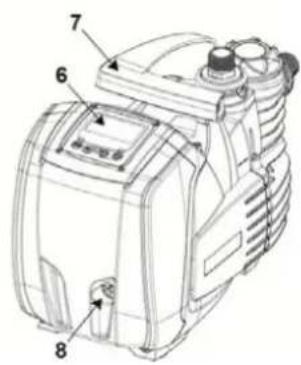
Kuva 1
natural_image
Line drawing of a portable industrial control panel with buttons and display (no text or symbols)
natural_image
Technical line drawing of a mechanical device with internal components and a downward arrow indicating motion (no text or symbols)
2
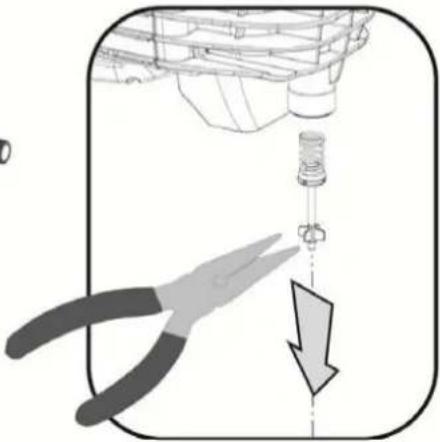
natural_image
Illustration of a mechanical assembly with a tool and a downward arrow indicating a process (no text or symbols)
3
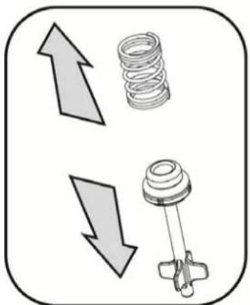
natural_image
Diagram showing two opposing arrows pointing upward and downward, with a spring and mechanical component below (no text or symbols)
4
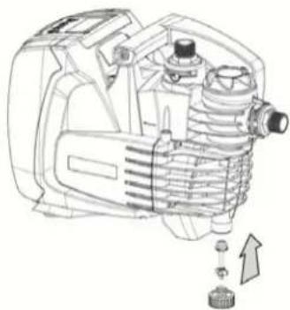
natural_image
Technical line drawing of an industrial engine with internal components and a directional arrow indicating motion (no text or symbols)
Kuva 5
9. HUOLTO
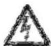
natural_image
Technical line drawing of a mechanical device with internal components (no text or symbols)
Kuva 6
SUOMI
Figura 7
natural_image
Technical line drawing of a mechanical device with no visible text or symbols
2.
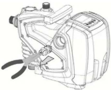
natural_image
Technical line drawing of a mechanical device with a tool inserted, showing internal components and mounting points (no text or symbols)
3.
natural_image
Illustration of a faucet with a water tap and pipe (no text or symbols)
- Kuva 8

natural_image
Technical line drawing of a mechanical device with a cable and connector (no text or symbols)
1.

natural_image
Line drawing of a portable electric stove or blender unit with a handle and control panel (no text or symbols)
- Kuva 9
10. VIANETSINTÄ
-
OPLOSSEN VAN PROBLEMEN.... 174
-
AFVOER ALS AFVAL 175
-
GARANTIE 175
LEGENDA

natural_image
Line drawing of a control panel with buttons labeled MODE, SET, and directional indicators (no text or symbols beyond basic labels)
5.6.6 AY: Anti Cycling
natural_image
Technical line drawing of a mechanical component with internal gears and housing (no text or symbols)
Afb. 6
NEDERLANDS
Afb. 7
natural_image
Technical line drawing of a mechanical device with gears and housing (no text or symbols)
2.

natural_image
Technical line drawing of a mechanical device with pliers and adjustment knobs (no text or symbols)
3.

natural_image
Illustration of a faucet with a valve and handle, no text or symbols present
- Afb. 8

natural_image
Technical line drawing of a mechanical device with a cable and adjustment knob (no text or symbols)
1.

natural_image
Line drawing of a portable air conditioner unit with a handle and control panel (no text or symbols)
- Afb. 9
10. OPLOSSEN VAN PROBLEMEN
11. AFVOER ALS AFVAL
natural_image
Line drawing of a control panel with buttons labeled MODE, SET, and directional indicators (no text or symbols beyond basic labels)
natural_image
Technical line drawing of a mechanical device with internal components and a downward arrow indicating motion (no text or symbols)
2
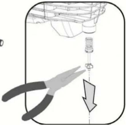
natural_image
Illustration of a mechanical assembly with a pliers and a downward arrow indicating a process (no text or symbols)
3
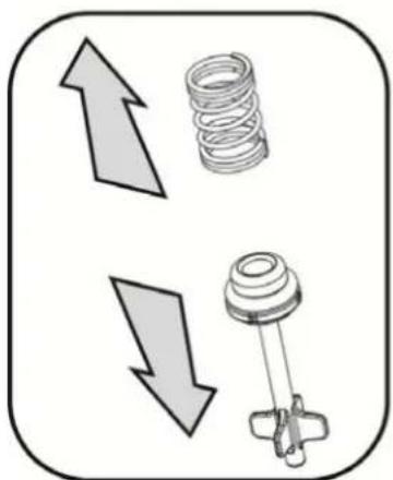
natural_image
Diagram showing two directional arrows pointing up and down, next to a spring and mechanical component (no text or symbols)
4
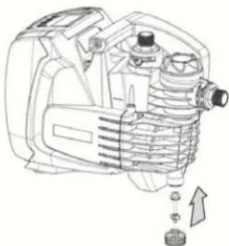
natural_image
Technical line drawing of a mechanical device with internal components and a directional arrow (no text or symbols)
Рисунок 5
natural_image
Technical line drawing of a mechanical component with internal gears and housing (no text or symbols)
Рисунок 6
РУССКИЙ
Рисунок 7
9.2 Слив системы
natural_image
Technical line drawing of a mechanical device with no visible text or symbols
2.
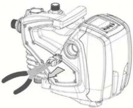
natural_image
Technical line drawing of a mechanical device with a pliers and adjustment knob (no text or symbols)
3.
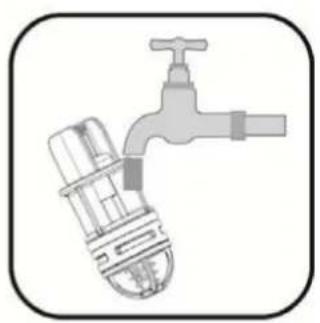
natural_image
Illustration of a faucet with a valve and handle (no text or symbols)
4.
Рисунок 8

natural_image
Technical line drawing of a mechanical device with a cable and adjustment knob (no text or symbols)
1.
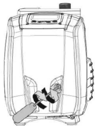
natural_image
Line drawing of a portable device with a handle and internal components (no text or symbols)
- Рисунок 9
10. РЕШЕНИЕ ПРОБЛЕМ

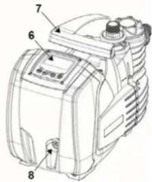
1.1 Vstavaný menič
natural_image
Line drawing of a control panel with buttons labeled MODE, SET, and directional icons (no text or symbols beyond basic labels)
natural_image
Technical line drawing of a mechanical device with internal components (no text or symbols)
Obrázok 6
Obrázok 7
natural_image
Technical line drawing of a mechanical device with no visible text or symbols
2.
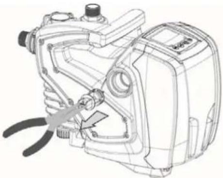
natural_image
Technical line drawing of a mechanical device with a tool inserted, showing internal components and no visible text or symbols.
3.
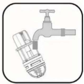
natural_image
Illustration of a faucet with a valve and handle (no text or symbols)
4.
Obrázok 8

natural_image
Technical line drawing of a mechanical device with a screw and adjustment knob (no text or symbols)
1.
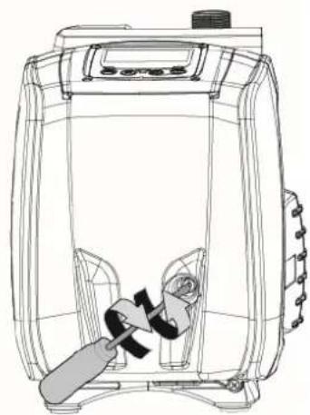
natural_image
Line drawing of a portable air conditioner unit with internal components and control panel (no text or symbols)
- Obrázok 9
10. RIEŠENIE PROBLÉMOV
Pred zahájením vyhladávania porúch je potrebné prerušit' elektrické napájanie čerpadla (vytiahnut' zástrčku napájacieho kábla zo zásuvky elektrickej siete).