
D-CW 200 - Water pump TALLAS - Free user manual and instructions
Find the device manual for free D-CW 200 TALLAS in PDF.

| Product type | Submersible water pump |
| Brand | TALLAS |
| Model | D-CW 200 |
| Applications | Clear water drainage, basement dewatering, garage, sump pit, gardening |
| Pumpable liquids | Clear water, rainwater, clear wastewater (max particles 5 mm) |
| Supply voltage | 220-240 V AC, 50 Hz |
| Nominal power consumption | 220 W |
| Nominal current | 0.9 A |
| Capacitor | 4 μF, 450 V |
| Max flow rate | 95 L/min |
| Max head | 5.5 m (0.55 bar) |
| Max immersion depth | 7 m |
| Auto start height | 220 mm |
| Auto stop min/max height | 60/110 mm |
| Residual water height (forced operation) | 2-3 mm |
| Power cable length | 10 m (type H05 RNF) |
| Motor protection rating | IP X8 |
| Insulation class | B |
| Liquid temperature | 0 °C to +35 °C |
| Ambient temperature | -10 °C (storage) to +40 °C (operation) |
| Net weight | 3.75 kg |
| Gross weight | 4.7 kg |
| Discharge connection | 1" 1/4 F (threaded) |
| Minimum sump pit dimensions | Base 460x460 mm, depth 400 mm |
| Operation | Manual or automatic (float switch) |
| Motor protection | Built-in thermal-overload protection (auto restart) |
| Maintenance | Regular cleaning of the suction strainer and impeller |
| Warranty | 24 months (wear parts excluded) |
| Spare parts | Available for 5 years after manufacture |
Frequently Asked Questions - D-CW 200 TALLAS
User questions about D-CW 200 TALLAS
0 question about this device. Answer the ones you know or ask your own.
Ask a new question about this device
Download the instructions for your Water pump in PDF format for free! Find your manual D-CW 200 - TALLAS and take your electronic device back in hand. On this page are published all the documents necessary for the use of your device. D-CW 200 by TALLAS.
USER MANUAL D-CW 200 TALLAS
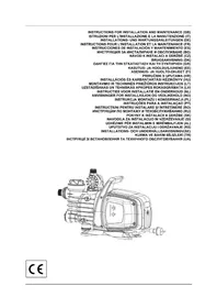
INSTRUCTIONS FOR INSTALLATION AND MAINTENANCE (GB) ISTRUZIONI PER L'INSTALLAZIONE E LA MANUTENZIONE (IT) INSTALLATIONS- UND WARTUNGSANLEITUNGEN (DE) INSTRUCTIONS POUR L'INSTALLATION ET LA MAINTENANCE (FR) INSTRUCCIONES DE INSTALACIÓN Y MANTENIMIENTO (ES) ИНСТРУКЦИЯ ЗА ИНСТАЛИРАНЕ И ОБСЛУЖВАНЕ (BG) NÁVOD K INSTALACI A ÚDRŽBĚ (CZ) BRUGSANVISNING (DK) ОДНГІЕЗ ГІА ТНН ЕГКАТАΣТАЗН КАІ ТН ΣΥΝΤΗΡΗΣΗ (GR) KASUTUS- JA HOOLDUSJUHEND (EE) ASENNUS- JA HUOLTO-OHJEET (FI) PRIRUČNIK S UPUTAMA (HR) INSTALLÁCIÓS ÉS KARBANTARTÁSI KÉZIKÖNYV (HU) MONTAVIMO IR TECHNINÈS PRIEŽIÜROS INSTRUKCIJOS (LT) UZSTÄDĪŠANAS UN TEHNISKĀS APKOPES ROKASGRĀMATA (LV) INSTRUCTIES VOOR INSTALLATIE EN ONDERHOUD (NL) ANVISNINGER FOR INSTALLASJON OG VEDLIKEHOLD (NO) INSTRUKCJA MONTAŽU I KONSERWACJI (PL) INSTRUÇÕES PARA A INSTALAÇAO (PT) INSTRUCTIUNI PENTRU INSTALARE ŚI ÎNTREȚINERE (RO) ИНСТРУКЦИИ ПО МОНТАЖУ И ТЕХОБСЛУЖИВАНИЮ (RU) РОКУNY K İNSTALÁCII A ÚDRŽBE (SK) NAVODILA ZA İNSTALACIJO IN VZDRŽEVANJE (SI) UDHĚZIME PËR INSTALIMIN E MIRËMBAJTJEN (AL) UPUTSTVO ZA INSTALACIJU I ODRŽAVANJE (RS) INSTALLATIONS- ОСН UNDERHÅLLSANVISNINGV(SE) KURMA VE BAKIM BİLGİLERİ (TR) ИНСТРУКЦІЇ ЗІ ВСТАНОВЛЕННЯ ТА ТЕХНІЧНОГО ОБСЛУГОВУВАННЯ (UA)
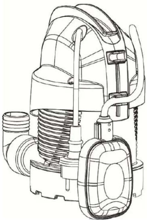
natural_image
Technical line drawing of a vacuum cleaner assembly (no text or labels)CE
ENGLISH Pag. 1
ITALIANO Pag. 5
DEUTSCH Seite 9
FRANÇAIS Page 13
ESPAÑOL Pág. 17
БЪЛГАРСКИ Стр. 21
ČESKY Strana 25
DANSK Side 29
ΕΛΛΗΝΙΚΑ Σελ. 33
EESTI Lk. 38
SUOMI Sivu 42
HRVATSKI Stranica 46
MAGYAR Oldal 50
LIETUVIŲ Psl. 54
LATVIEŠU Lpp. 58
NEDERLANDS Pag. 62
NORSK Pag. 66
POLSKI Strona 70
PORTUGUÊS Pag. 74
ROMÂNĂ Pag. 78
РУССКИЙ Стр. 82
SLOVENSKY Str. 86
SLOVENŠČINA Str. 90
SHQIP Pag. 94
SRPSKI Str. 98
SVENSKA Sid. 102
TÜRKÇE Sf. 106
natural_image
Technical line drawing of a mechanical component with no visible text or symbols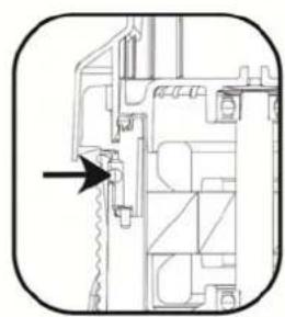
natural_image
Technical line drawing of a mechanical assembly with an arrow indicating a specific component (no text or symbols present)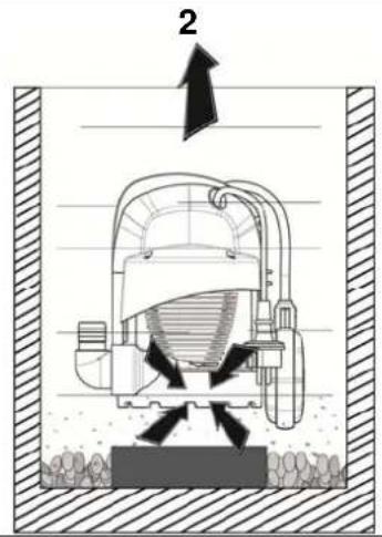
natural_image
Line drawing of a hand operating a vacuum cleaner with a magnified top component (no text or symbols)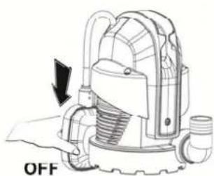
natural_image
Technical illustration of a mechanical device with an arrow indicating 'OFF' (no text or symbols on the device itself)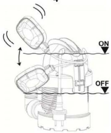
natural_image
Technical diagram of a mechanical assembly with no visible text or symbols
natural_image
Line drawing of a mechanical device with no visible text or symbols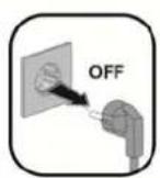
natural_image
Technical line drawing of a mechanical device with internal components and a screwdriver (no text or symbols)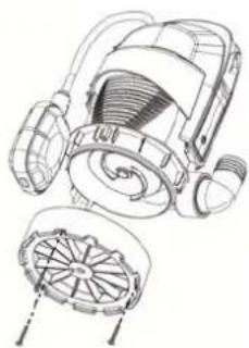
natural_image
Technical line drawing of a mechanical device with internal components and a separate cross-sectional view (no text or symbols)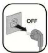

natural_image
Technical line drawing of a mechanical device with internal components and a fan-like base (no text or symbols)INDEX
- APPLICATIONS....1
- PUMPABLE LIQUIDS....1
- TECHNICAL DATA AND LIMITATIONS OF USE 1
- MANAGEMENT....2
4.1 Storage....2
4.2 Transport....2
4.3 Weight and dimensions....2
- WARNINGS....2
- INSTALLATION ...... 2
- ELECTRICAL CONNECTION....3
- START-UP 3
- PRECAUTIONS......3
- MAINTENANCE AND CLEANING 3
10.1 Cleaning the suction grid....4
10.2 Cleaning the impeller....4
-
TROUBLESHOOTING....4
-
GUARANTEE 4
WARNINGS

Read
documentation before installation.
all this carefully

Take out the plug before any intervention. Absolutely avoid dry: the pump must be activated exclusively when it is immersed in the water is finished, the pump must be deactivated immediately, the plug out of the socket.
1. APPLICATIONS
The pumps are of the submersible type, designed and made for pumping clear, for domestic uses, with manual or automatic operation, for drying basements and garages subject to flooding, for pumping drainage wells, pumping rainwater collecting traps or infiltrations from roof gutters, etc.
Thanks to their compact and handy shape, they are also used for particular applications as portable pumps for emergency situations such as for drawing water from tanks or rivers, draining swimming pools and fountains, excavations or underpasses. Also suitable for gardening and general hobby activity.

These pumps cannot be used in swimming pools, ponds or basins where people are present, or for pumping hydrocarbons (petrol, diesel fuel, combustible oils, solvents, etc.) in accordance with the accident-prevention regulations in force. They are not designed for continuous use, but for emergency use over a limited period. They should be cleaned before putting them away. See the chapter “Maintenance and Cleaning”.
2. PUMPABLE LIQUIDS
| Fresh water | ● |
| Rainwater | ● |
| Clear waste water | ● |
| Dirty water ○ | |
| Foul waste water containing solid bodies with long fibres | ○ |
| Fountain water | ● |
| River or lake water | ● |
| Max. particle dimension [mm] ∅ 5 |
Table 1
- Suitable
- Not suitable
The pump is watertight and must be immersed in liquid to a maximum depth of 7m. See Table 3.
3. TECHNICAL DATA AND LIMITATIONS OF USE
• Supply voltage: 220-240V, see electrical data plate
- Delayed line fuses (220-240V version): indicative values (Ampere)
• Storage temperature: -10^ +40^
| Line fuses 220-240V 50Hz |
| 2 |
Table 2
| Draining clear water | ||
| Model PI=220 | ||
| Electrical data | P1 Rated absorbed power [W] | 220 |
| Mains voltage [V] 220-240 AC | ||
| Mains frequency [Hz] 50 | ||
| Current [A] 0.9 | ||
| Capacitor [μF] 4 | ||
| Capacitor [Vc] 450 | ||
| Hydraulic data | Max. flow rate [l/min] | 95 |
| Max. head [m] 5.5 | ||
| Max. head [bar] 0.55 | ||
| Max. immersion depth [m] 7 | ||
| Min. AUT starting height [mm] 220 | ||
| Min./max. stopping height [mm] 60/110 | ||
| Residual water height [mm] | 2-3 | |
| Range of use | Length of power cable [m] | 10 |
| Type of cable | H05 RNF | |
| Grade of motor protection | IP X8 | |
| Insulation class | B | |
| Liquid temperature range [°C] according to EN 60335-2-41 for domestic use | 0 °C / +35 °C | |
| Max. particle dimension [mm] | ∅ 5 | |
| Max. ambient temperature [°C] | +40 °C | |
| Weight | DNM GAS | 1" 1/4 F |
| Net/Gross weight approx. [kg] | 3.75 / 4.7 |
Table 3

The pump which does not stand on a base cannot support the weight of the pipes, which must be supported in some other way.
4. MANAGEMENT
4.1 Storage
All the pumps must be stored in a dry covered place, with possible constant air humidity, free from vibrations and dust. They are supplied in their original pack in which they must remain until the time of installation.
4.2 Transport
Avoid subjecting the products to needless impacts and collisions.
4.3 Weight and dimensions
The adhesive plate on the packaging indicates the total weight of the pump and its dimensions.
5. WARNINGS

The pumps must never be carried, lifted or allowed to operate suspended from the power cable; use the handle provided.
- The pump must never be allowed to run when dry.
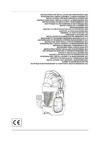
- On the body there is a venting hole to avoid phenomena of cavitation when starting the pump. It is therefore normal for a small amount of water to come out of the pump during operation. (Fig.1).
- The sealing device contains lubricant which is non-toxic but which may alter the characteristics of the water, in the case of pure water, if the pump were to have any leaks.
6. INSTALLATION
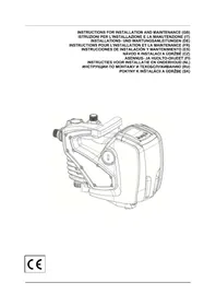
Screw on the elbow with hosetail fitting provided in the packaging. For the clear water version there are two fittings, one 25 mm and one 30 mm; if you want to use a pipe with a larger diameter, change the elbow coupling. Use a pipe tightening clamp to secure the pipe to the fitting.
- If the bottom of the trap where the pump is to be placed is particularly dirty, a raised support should be provided so as to avoid blocking of the suction grid (Fig.2)
• Totally immerse the pump in the water. - Ensure that the minimum dimensions of the trap in which it is housed are as follows:
Min. base dimensions (mm) 460x460 / Min. height (mm) 400 - Pay attention to ensure that the float is free to move, leave at least 5 cm from the wall of the trap.
ENGLISH
- The dimensions of the trap must always be in relation to the quantity of water arriving and to the flow of the pump, so as not to subject the motor to excessive starts/hour; it is strongly recommended not to exceed 20 starts/hour.

The pump must be installed in vertical position!
7. ELECTRICAL CONNECTION

The length of the power cable on the pump limits the maximum depth of immersion in use of the pump. Follow the indications on the technical data plate and in this manual, table 3.
8. START-UP
There are two operating modes:
- MANUAL (A)
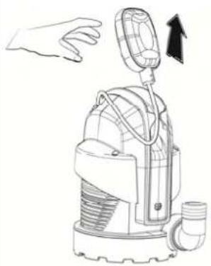
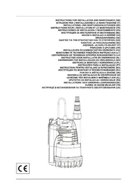
Although they have a float, the pumps can be used in manual mode Fig.3
1) Fix the float switch so that it remains vertical above the pump (with the cable below) (a). As long as the float switch remains raised, the pump keeps operating irrespective of the water level.
2) Insert the plug of the power cable in a 220-240V power socket.
3) The pump will start up; ensure that it is immerse in the liquid to be pumped.
Pay attention because the pump will not switch off automatically once it reaches the minimum level; it must be switched off manually by the user, either by taking the power out of the socket or by lowering the float (automatic operation).
The maximum suction level is reached only during manual operation because, in automatic operating condition, the automatic float switch stops the pump before it reaches that level.
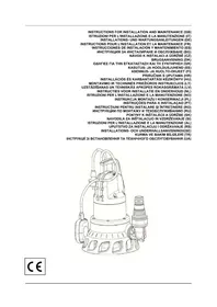
• AUTOMATIC (B)
The models with a float switch are started automatically when the water level rises and will switch off when the required minimum level is reached (Fig.4).
1) Leave the float free to move.
2) Insert the plug of the power cable in a 220-240V power socket.
3) When the float reaches the ON level the pump will start and will continue operating until it reaches the OFF level.
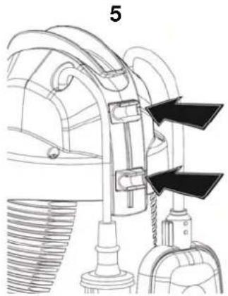
Regulating the starting/stopping height:
(To know the minimum starting and stopping height, see the Technical Data chapter.)
The cable length must on one hand allow the float switch to move freely and, on the other, prevent it resting on the bottom. The portion of cable between the float switch and the cable stay notch must not be less than 10 cm long. The shorter the portion of cable between the float switch and the cable stay notch, the lower will be the starting height and the higher the stopping height. The fixing point can be changed, for example on the lower clip, with the same length, this will give a lower stopping and starting level (Fig.5). The pump is supplied with a clamp (Fig. 6) that fixes the float cable and prevents it sliding in the clip; if you decide to lengthen or shorten the free float cable, shift the corresponding clamp if it cannot be replaced. The single-phase motors are equipped with built-in thermal overload protection and can be connected directly to the mains. NB: if the motor is overloaded it stops automatically. Once it has cooled it starts again automatically without requiring any manual intervention.
9. PRECAUTIONS
RISK OF FROST: when the pump remains inactive at a temperature lower than 0^ C, it is necessary to ensure that there is no water residue which could freeze, causing cracks in the plastic parts.
If the pump has been used with substances that tend to form a deposit, or with water containing chlorine, rinse it after use with a powerful jet of water in order to avoid the formation of deposits or encrustations which would reduce the characteristics of the pump.
10. MAINTENANCE AND CLEANING
In normal operation the pump does not require any type of maintenance. In any case, all repair and maintenance work must be carried out only after having disconnected the pump from the supply mains. When restarting the pump, ensure that the suction filter is always fitted so as not to create the risk or possibility of accidental contact with moving parts.
ENGLISH
10.1 Cleaning the suction grid
(Fig.7)
- Switch off the electric power supply to the pump.
- Drain the pump.
- Unscrew the retaining screws on the filter (b).
- Remove the suction grid (c)
- Clean and reassemble the suction grid.
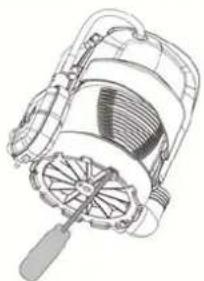
10.2 Cleaning the impeller
(Fig.8)
Switch off the electric power supply to the pump.
- Drain the pump.
• Unscrew the retaining screws on the filter (b). - Remove the suction grid (c)
- Wash the pump with clean water to remove possible impurities between the motor and the pump jacket. (d).
• Clean the impeller (d). - Check that the impeller can turn freely.
- Assemble the parts, proceeding in inverse order to disassembly.
11. TROUBLESHOOTING

Before taking any troubleshooting action, disconnect the pump from the power supply (i.e. remove the plug from the socket). If there is any damage to the power cable or pump, any necessary repairs or replacements must be performed by the manufacturer or his authorized customer support service, or by an equally-qualified party, in order to prevent all risks.
| FAULTS | CHECKS (possible causes) | REMEDIES | |
| 1 | The motor does not start and does not make any noise. | A. Check that voltage is reaching the motor.B. Check the protection fuses.C. The switch is not activated by the float. | A. Check that the plug is inserted correctly.B. If burnt out, change them.- If burnt out, change them. Place it facing up.- Increase the depth of the trap. |
| 2 | The pump does not deliver flow | A. The suction grid or the pipes are blocked.B. The impeller is worn or blocked.C. The head required is higher than the pump's characteristics.D. Presence of air | A. Remove the obstructions or straighten the hose if it is twisted.B. Replace the impeller or remove the obstruction.C. Replace it with one with a higher head.D. Wait at least 1 minute until it is eliminated |
| 3 | The pump does not stop. | A. The switch is not deactivated by the float A. Check that the float can move freely. | |
| 4 | The flow rate is insufficient | A. Check that the suction grid is not partially blockedB. Check that the impeller or the delivery pipe are not partly blocked or encrusted.C. Ensure that the check valve (if contemplated) is not partially blocked | A. Remove any obstructions.B. Remove any obstructions.C. Accurately clean the check valve |
| 5 | The pump stops after having run for a short time. | A. The thermal overload protection device stops the pump. | A. Check that the fluid to be pumped is not too dense as it would cause overheating of the motor.B. Check that the water temperature is not too high. |
12. GUARANTEE

Any modification made without prior authorisation relieves the manufacturer of all responsibility. All the spare parts used in repairs must be authentic and all accessories must be authorised by the manufacturer, in order to ensure maximum safety of the machines and of the systems in which they may be installed.
This product is covered by a legal guarantee (in the European Community for 24 months from date of purchase) against all defects that can be assigned to manufacturing faults or to the material used.
The product under guarantee may, at discretion, either be replaced with one in perfect working order or replaced free of charge if the following conditions are observed:
- the product has been used correctly in compliance with the instructions and not attempt has been made to repair it by the buyer or by third parties.
- the product has been consigned to the outlet where it was purchased, attaching a document as proof of purchase (invoice or cash register receipt) and a brief description of the problem found.
The impeller and parts subject to wear are not covered by the guarantee. Intervention under guarantee does not extend the initial guarantee period in any way.
INDICE
- APPLICAZIONI 5
- LIQUIDI POMPABILI....5
- DATI TECNICI E LIMITAZIONI D'USO 5
- GESTIONE 6
2. SIURBIMUI TINKAMI VANDENYS
• MANUĀLAIS (A) REŽĪMS
INNEHÅLLSFÖRTECKNING
- ANVÄNDNINGSOMRÅDEN 102
- VÄTSKOR SOM KAN PUMPAS.... 102
- TEKNISKA DATA OCH ANVÄNDNINGSBEGRÄNSNINGAR.... 102
- HANTERING 103
- INDEX
- WARNINGS
- APPLICATIONS
- PUMPABLE LIQUIDS
- TECHNICAL DATA AND LIMITATIONS OF USE
- MANAGEMENT
- Storage
- Transport
- Weight and dimensions
- WARNINGS
- INSTALLATION
- ENGLISH
- ELECTRICAL CONNECTION
- START-UP
- - MANUAL (A)
- • AUTOMATIC (B)
- Regulating the starting/stopping height:
- PRECAUTIONS
- MAINTENANCE AND CLEANING
- Cleaning the suction grid
- (Fig.7)
- Cleaning the impeller
- (Fig.8)
- TROUBLESHOOTING
- GUARANTEE
- INDICE
- SIURBIMUI TINKAMI VANDENYS
- • MANUĀLAIS (A) REŽĪMS
- INNEHÅLLSFÖRTECKNING
Brand : TALLAS
Model : D-CW 200
Category : Water pump