DP16SL - Drill SCHEPPACH - Free user manual and instructions
Find the device manual for free DP16SL SCHEPPACH in PDF.
| Product type | Bench drill press |
| Brand | Scheppach |
| Model | DP16SL |
| Dimensions (L x W x H) | 235 x 482 x 730 mm |
| Weight | 22 kg |
| Power supply voltage | 230 V / 50 Hz |
| Motor power | 550 W |
| Spindle speeds | 510, 800, 1300, 1800, 2430 rpm |
| Max drilling capacity | 50 mm |
| Chuck holder | B16, clamping 1.5 to 13 mm |
| Column diameter | 48 mm |
| Table dimensions | 194 x 165 mm |
| Table tilt range | -45° / 0° / 45° |
| Table rotation | 360° |
| Chuck-table distance | 305 mm |
| Chuck-base distance | 405 mm |
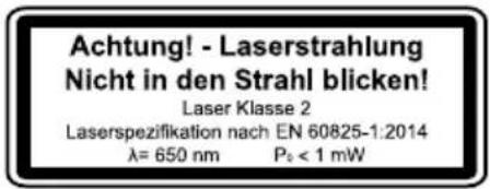
| Integrated laser | Class 2, wavelength 650 nm, power < 1 mW |
| Duty cycle | S2, 10 min (intermittent operation) |
| Sound pressure level | 69 dB(A) |
| Sound power level | 82 dB(A) |
| Vibration (hand-arm) | 2.5 m/s² |
| Cable length | 1830 mm |
| Protection features | Belt cover, chuck guard, automatic stop when cover is opened |
| Maintenance | Cleaning after use, regular lubrication of spindle and rack |
| Spare parts available | Pulley, V-belt, handle, chuck, drive shaft, complete laser |
Frequently Asked Questions - DP16SL SCHEPPACH
User questions about DP16SL SCHEPPACH
0 question about this device. Answer the ones you know or ask your own.
Ask a new question about this device
Download the instructions for your Drill in PDF format for free! Find your manual DP16SL - SCHEPPACH and take your electronic device back in hand. On this page are published all the documents necessary for the use of your device. DP16SL by SCHEPPACH.
USER MANUAL DP16SL SCHEPPACH

https://www.scheppach.com/da/service
Made in P.R.C.
DP16SL
| DE | Tischbohrmaschine Originalbetriebsanleitung | 8 |
| GB | Bench drill Translation of original instruction manual | 27 |
| FR | Perceuse à colonne d'établi Traduction des instructions d'origine | 42 |
| IT | Trapano da cavolo La traduzione dal manuale di istruzioni originale | 59 |
| NL | Tafelboormachine Vertaling van de originele gebruikshandleiding | 76 |
| ES | Taladradora de mesa Traducción del manual de instruetiones original | 92 |
| PT | Berbequim de bancada Traducción do manual de operação original | 109 |
| CZ | Stolní vrtačka Překlad originálího námodu k obšluge | 125 |
| SK | Stolová vrtačka Preklad originálného námodu na obšluhu | 140 |
| HU | Asztali fúrógép Eredetí használati utasítás fordításza | 156 |
| PL | Wiertarka stolowa Tlumaczenie oryginalnej instrukcji obstrugi | 172 |
| HR | Stolna bušilica Prijevod originalnog priručnika za uporabu | 189 |
| SI | Namizni vrtalni stroj Prevod originalnih navodil za uporabo | 204 |
| EE | Lauapuurmasin Originaalkäitusjuhendi tölge | 219 |
| LT | Stalinès gréžimo staklés Originalios naudojimo instrukcijos vertimas | 234 |
| LV | Galda urbjmašina Originalās lietošanas instrukcijas tulkojums | 249 |
| SE | Bänkborrmaskin Översättning av original-bruksanvising | 265 |
| FI | Pöytäporakone Käännös alkuperäisestä käytöohjeesta | 280 |
| DK | Bænboremaskine Oversætelse fra den oprindelige betjeningsvejledning | 295 |
| NO | Bordboremaskin Oversætelse av den originale brukerverledningen | 310 |
| BG | Hactoɪnha cβrɛdnoBbUHa MaɪshɪHa Преов на оригианною ръковodctBO за ekciploaataця | 325 |
| GR | Επιραπέζο δράπavo Μετάφραση Κου πρωτότυτου τών σθηγίων χρήσς | 343 |
| RO | Maşinia de găurit de banc Traducere din manualul de expoatare original | 361 |
| RS | Stona bušilica Prevod originalog uputstva za upotrebu | 377 |
| TR | Tezgah matkabī Original kullanim talimatu cevirisi | 393 |
DE: DP16SL Riemeneinstellung - Drehzahl
GB: DP16SL Belt setting - Speed
FR: Reglage de la courroie DP16SL - Régime
IT: DP16SL Regolazione della cinghia -Numero di giri
NL: DP16SL Rieminstelling - Toerental
ES: DP16SL Ajuste de la correa -Numero de revoluciones
PT: DP16SL Ajuste da correia - Velocidade
CZ: Nastaveni remenu DP16SL - Otáčky
SK: DP16SL Nastavenie remena - Otáčky
HU: DP16SL Szijbeallitas - Fordulatszam
PL: DP16SL Regulacja paska - Prędkość obrotowa
HR: DP16SL Namješanje remena - Brzina vrtnje
SI: DP16SL Nastavitev jermena - Stevilo vrtljajev
EE: DP16SL Rihma seadistamine - Pöördeary
LT: DP16SL Dirzo nustatymas - Suki skaicius
LV: DP16SL Siksnas iestatisanas apgriezenu skaits
SE: DP16SL Reminställning - Varvital
FI: DP16SL Hihnansaatö - kierrosluku
DK: DP16SL Remindstilling - Hastighed
NO: DP16SL Reiminnstilling - Turtall
BG:DP16SL PerynnpaHe Ha Pembka-Obopotn
GR: DP16SL Puroiion iavta-Apiuoc oTpoov
RO: DP16SL Reglare curea - Turatie
RS: DP16SL Podesavanje remena - Broj obrtaja
TR: DP16SL Kayis ayari - Devir sayisi
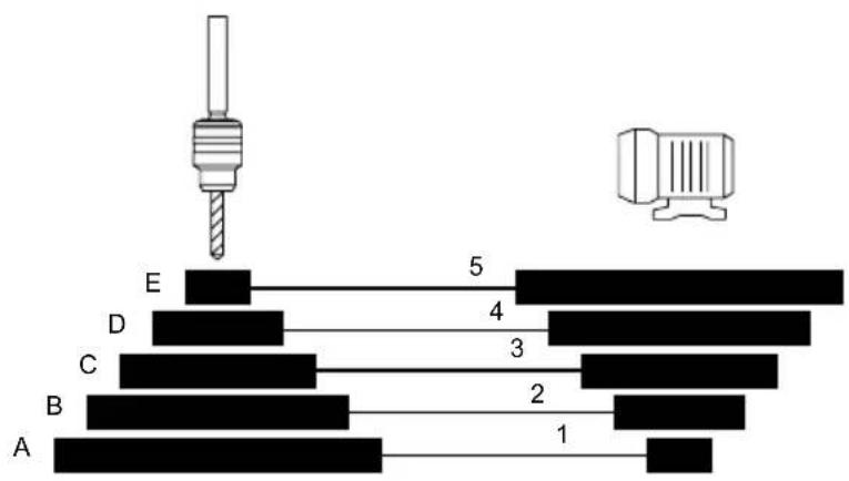
510 1/min A 1
800 1/min B 2
1300 1/min C 3
1800 1/min D 4
2430 1/min E5
Homepage: https://www.scheppach.com/de/service
Explanation of the symbols on the product
Symbols are used in this manual to draw your attention to potential hazards. The safety symbols and the accompanying explanations must be fully understood. The warnings themselves will not rectify a hazard and cannot replace proper accident prevention measures.
| Warning - Disregard results in a risk of death or injury, or damage to the tool! | |
| Warning - Read the operating manual to reduce the risk of injury. | |
| Wear safety goggles. Sparks created during work or fragments, chippings and dust ejected by the product can cause sight loss. | |
| Wear hearing protection. Exposure to noise can cause hearing loss. | |
| Wear a dust protection mask. When machining wood and other materials, harmful dust may be generated. Do not machine material containing asbestos! | |
| Do not leave long hair loose. Use a hair net. | |
| Do not wear gloves during operation. | |
| Attention! Laser beam | |
| The product complies with the applicable European directives. | |
| The product complies with the applicable Serbian directives. |
Table of contents: Page:
- Introduction 29
- Product description (Fig. 1) 29
- Scope of delivery 29
- Proper use 30
- General safety instructions 30
- Residual risks 33
- Technical data 33
- Unpacking 34
- Assembly 34
- Settings 35
- Commissioning 35
- Electrical connection 38
- Transport 38
- Cleaning and maintenance 38
- Repair & ordering spare parts 39
- Storage 40
- Disposal and recycling 40
- Troubleshooting 40
- Declaration of conformity 409
1. Introduction
Manufacturer:
Scheppach GmbH
GünzburgerstraBe 69
D-89335 Ichenhausen
Dear Customer,
We hope your new product brings you much enjoyment and success.
Note:
In accordance with the applicable product liability laws, the manufacturer of this product assumes no liability for damage to the product or caused by the product arising from:
- Improper handling
- Failure to comply with the operating manual
- Repairs carried out by third parties, unauthorised specialists
- Installing and replacing non-original spare parts
- Improper use
- Failure of the electrical system in the event of the electrical regulations and VDE provisions 0100, DIN 57113 / VDE 0113 not being observed
Note:
The operating manual is part of this product. It includes important instructions for the safe, proper and economic operation of the product, for avoiding danger, for minimising repair costs and downtimes and for increasing the reliability and extending the service life of the product. In addition to the safety instructions in this operating manual, you must also observe the regulations applicable to the operation of the product in your country. Familiarise yourself with all operating and safety instructions before using the product. Only operate the product as described and for the specified areas of application. Keep the operating manual in a good place and hand over all documents when passing the product on to third parties.
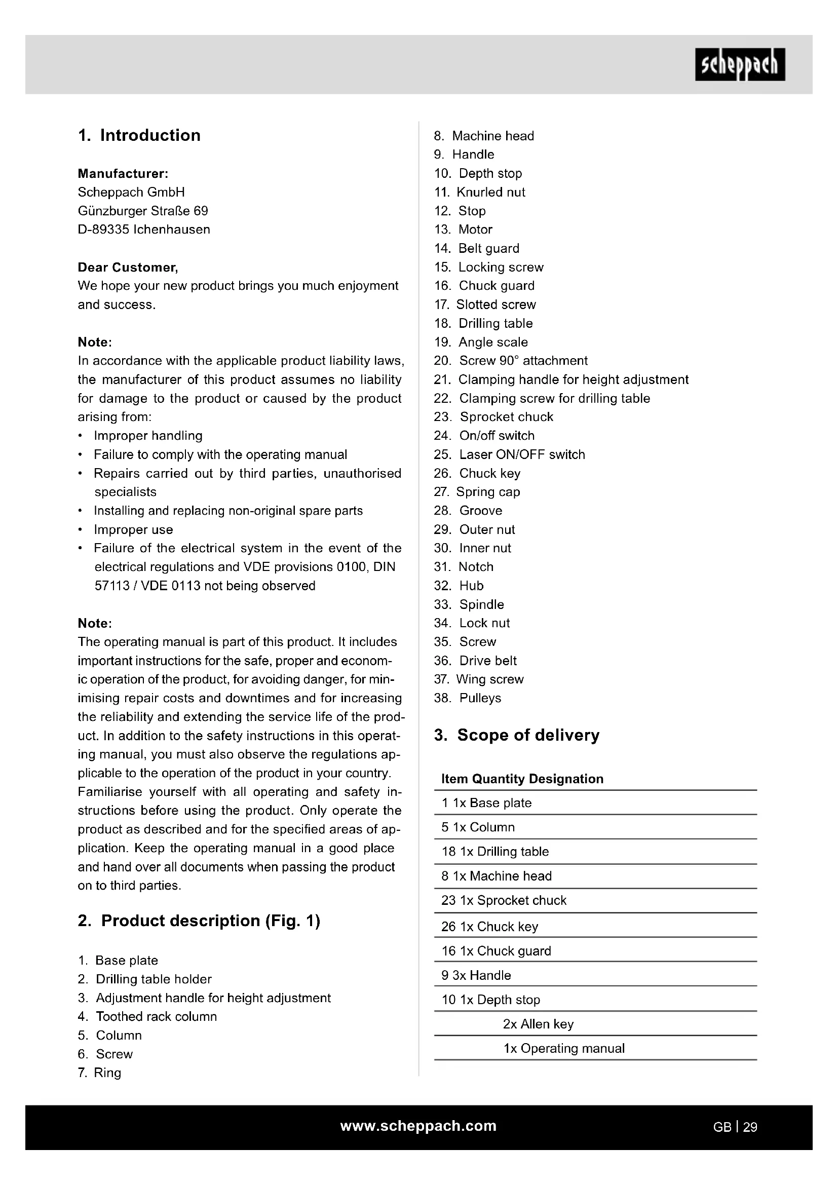
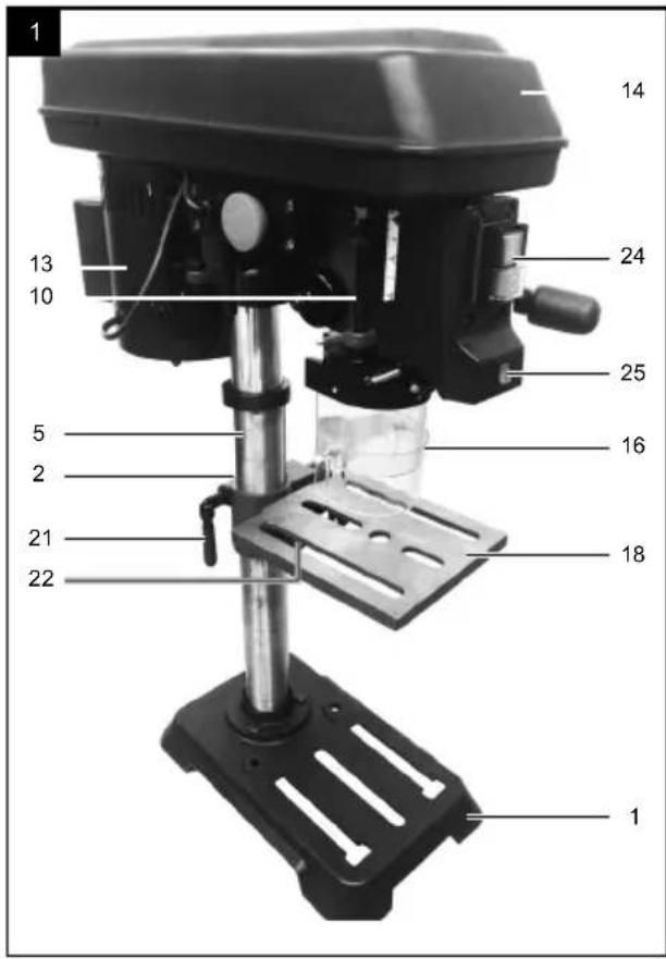
2. Product description (Fig. 1)
- Base plate
- Drilling table holder
- Adjustment handle for height adjustment
- Toothed rack column
- Column
- Screw
-
Ring
-
Machine head
- Handle
- Depth stop
- Knurled nut
- Stop
- Motor
- Belt guard
- Locking screw
- Chuck guard
- Slotted screw
- Drilling table
- Angle scale
- Screw 90^ attachment
- Clamping handle for height adjustment
- Clamping screw for drilling table
- Sprocket chuck
- On/off switch
- Laser ON/OFF switch
- Chuck key
- Spring cap
- Groove
- Outer nut
- Inner nut
- Notch
- Hub
- Spindle
- Lock nut
- Screw
- Drive belt
- Wing screw
- Pulleys
3. Scope of delivery
Item Quantity Designation
| 1 1x Base plate |
| 5 1x Column |
| 18 1x Drilling table |
| 8 1x Machine head |
| 23 1x Sprocket chuck |
| 26 1x Chuck key |
| 16 1x Chuck guard |
| 9 3x Handle |
| 10 1x Depth stop |
| 2x Allen key |
| 1x Operating manual |
4. Proper use
The bench drill is intended to drill metal, plastic, wood and similar materials, and may only be used in private households.
Food and materials that pose a health hazard are not permitted to be processed using the machine.
The chuck is only suitable for use with drill bits and tools with a shaft diameter of 1.5 - 13mm and a cylindrical tool shaft. Furthermore, tools with a tapered shaft can also be used.
The product is intended for use by adults. The product is not intended for use by people under the age of 16. Children under the age of 16 may only use the product when supervised.
The product may only be used in the intended manner. Any use beyond this is improper. The user/operator, not the manufacturer, is responsible for damages or injuries of any type resulting from this.
An element of the intended use is also the observance of the safety instructions, as well as the assembly instructions and operating information in the operating manual. Persons who operate and maintain the product must be familiar with the manual and must be informed about potential dangers.
The liability of the manufacturer and resulting damages are excluded in the event of modifications of the product. The product may only be operated with original parts and original accessories from the manufacturer.
The safety, operating and maintenance specifications of the manufacturer, as well as the dimensions specified in the technical data, must be observed.
Please note that our products were not designed with the intention of use for commercial or industrial purposes. We assume no guarantee if the product is used in commercial or industrial applications, or for equivalent work. The manufacturer is not liable for damage caused by improper use or incorrect operation.
Explanation of the signal words in the operating manual
DANGER
Signal word to indicate an imminently hazardous situation which, if not avoided, will result in death or serious injury.
WARNING
Signal word to indicate a potentially hazardous situation which, if not avoided, could result in death or serious injury.
CAUTION
Signal word to indicate a potentially hazardous situation which, if not avoided, could result in minor or moderate injury.
ATTENTION
Signal word to indicate a potentially hazardous situation which, if not avoided, could result in product or property damage.
5. General safety instructions
General power tool safety warnings
WARNING! Read all safety warnings, instructions, illustrations and specifications provided with this power tool. Failure to follow all instructions listed below may result in electric shock, fire and/or serious injury.
Save all warnings and instructions for future reference.
The term "power tool" in the warnings refers to your mains-operated (corded) power tool or battery-operated (cordless) power tool.
1) Work area safety
a) Keep your work area clean and well-lit. Cluttered or dark areas invite accidents.
b) Do not operate power tools in explosive atmospheres, such as in the presence of flammable liquids, gases or dust. Power tools create sparks which may ignite the dust or fumes.
c) Keep children and bystanders away while operating a power tool. Distractions can cause you to lose control.
2) Electrical safety
a) Power tool plugs must match the outlet. Never modify the plug in any way. Do not use any adapter plugs with earthed (grounded) power tools. Unmodified plugs and matching outlets will reduce risk of electric shock.
b) Avoid body contact with earthed or grounded surfaces, such as pipes, radiators, ranges and refrigerators. There is an increased risk of electric shock if your body is earthed.
c) Do not expose power tools to rain or wet conditions. Water entering a power tool will increase the risk of electric shock.
d) Do not use the cable for another purpose, for example, carrying or hanging the power tool or pulling the plug out of the socket. Keep the cable away from heat, oil, sharp edges or moving device parts. Damaged or coiled cables increase the risk of an electric shock.
e) If you work with an electric tool outdoors, only use extension cables that are also suitable for outdoor use. Use of a cord suitable for outdoor use reduces the risk of electric shock.
f) If operating a power tool in a damp location is unavoidable, use a residual current device (RCD) protected supply. Use of an RCD reduces the risk of electric shock.
3) Personal safety
a) Stay alert, watch what you are doing and use common sense when operating a power tool. Do not use a power tool while you are tired or under the influence of drugs, alcohol or medication. A moment of carelessness when using power tools can result in serious injuries.
b) Wear personal protective equipment and always safety goggles. Protective equipment such as a dust mask, non-skid safety shoes, safety helmet or hearing protection used for appropriate conditions will reduce personal injuries.
c) Prevent unintentional starting. Ensure the switch is in the off-position before connecting to power source and/or rechargeable battery, picking up or carrying the tool. Carrying electric tools with your finger on the switch or connecting power tools to the power supply when they are already switched on invites accidents.
d) Remove any adjusting tools or spanners/keys before turning the power tool on.
A tool or spanner that is located in a rotating device part may result in injuries.
e) Avoid abnormal postures. Keep proper footing and balance at all times. This enables better control of the power tool in unexpected situations.
f) Wear suitable clothing. Do not wear loose clothing or jewellery. Keep hair, clothing and gloves away from moving parts. Loose clothes, jewellery or long hair can be caught in moving parts.
g) If dust extraction and collection devices can be mounted, make sure that they are connected and used properly.
Use of dust extraction can reduce dust-related hazards.
h) Do not let familiarity gained from frequent use of tools allow you to become complacent and ignore tool safety principles. A careless action can cause severe injury within a fraction of a second.
4) Power tool use and care
a) Do not overload the device. Use the correct power tool for your application. The correct power tool will do the job better and safer at the rate for which it was designed.
b) Do not use the power tool if the switch does not turn it on and off. Any power tool that cannot be controlled with the switch is dangerous and must be repaired.
c) Disconnect the plug from the power source and/or remove the battery pack, if detachable, from the power tool before making any adjustments, changing accessories, or storing power tools. Such preventive safety measures reduce the risk of starting the power tool accidentally.
d) Store idle power tools out of the reach of children. And do not allow persons unfamiliar with the power tool or these instructions to operate the power tool. Power tools are dangerous in the hands of untrained users.
e) Maintain power tools and tool attachments with care. Check whether moving parts function properly and do not get stuck and whether parts are broken or are damaged and thus adversely affect the electric tool function. If damaged, have the power tool repaired before use. Many accidents are caused by poorly maintained power tools.
f) Keep cutting tools sharp and clean. Properly maintained cutting tools with sharp cutting edges are less likely to bind and are easier to control.
g) Use the power tool, accessories and tool attachments etc. in accordance with these instructions. Take into account the working conditions and the work to be performed. Use of the power tool for operations different from those intended could result in a hazardous situation.
h) Keep handles and grasping surfaces dry, clean and free from oil and grease. Slippery handles and grasping surfaces do not allow for safe handling and control of the tool in unexpected situations.
5) Service
a) Only have your power tool repaired by qualified specialists and only with original spare parts. This ensures that safety of the electric tool is maintained.
Safety instructions for drills
a) The drill must be secured. An incorrectly secured drill can move or topple and this can result in injuries.
b) The workpiece must be clamped or fastened to the workpiece support. Do not drill into workpieces that are too small to be securely clamped. Holding the workpiece by hand can lead to injuries.
c) Do not wear gloves. Gloves can be caught by rotating parts or drilling debris and thus cause injuries.
d) Keep your hands away from the drilling area whilst the power tool is running. Contact with rotating parts or drilling debris can cause injuries.
e) The drill must be turning before it makes contact with the workpiece. Otherwise, the drill bit can catch in the workpiece and this can result in an unexpected movement of the workpiece and cause injuries.
f) If the drill becomes jammed, stop pressing downwards and switch the power tool off. Investigate and rectify the cause of the jamming. Jamming can result in an unexpected movement of the workpiece and can result in serious injuries.
g) Avoid long pieces of drill swarf by interrupting the downward pressure at regular intervals. Sharp metal swarf can become tangled and lead to injuries.
h) Never remove drilling debris from the drilling area whilst the power tool is running. To remove swarf, move the drill away from the workpiece, switch off the power tool and wait until the drill has come to a standstill. Use an aid such as a brush or a hook to remove the swarf. Contact with rotating parts or drilling debris can cause injuries.
i) The permissible rotational speed for tool attachments with a rated speed must be at least as high as the highest speed cited on the power tool. Accessories which rotate faster than the maximum permissible rate can break and throw pieces into the air.
ATTENTION: Laser beam
Do not look into the beam
Laser class 2
Protect yourself and you environment from accidents using suitable precautionary measures!
- CAUTION
- Do not look directly into the laser beam with unprotected eyes.
- Never look into the path of the beam.
- Never point the laser beam towards reflecting surfaces and persons or animals. Even a laser beam with a low output can cause damage to the eyes.
Methods other than those specified here can result in dangerous radiation exposure. - Never open the laser module. Unexpected exposure to the beam can occur.
- If the product is not used for an extended period of time, the batteries should be removed.
- The laser may not be replaced with a different type of laser.
- Repairs of the laser may only be carried out by the laser manufacturer or an authorised representative.
Adhere to the correct mains voltage!
Ensure that the mains voltage corresponds to the specifications on the type plate.
Use an earthed socket!
The product may only be operated using a socket with properly installed fuse protection.
Work area safety
Ensure that the machine is stable and secure. If possible, secure the machine to a floor plate or a workbench.
Protection against electric shock!
Protect the product from moisture. The product must not be moist nor operated in a moist environment. Check the product and the mains connection cable with plug prior to each use. Avoid physical contact with earthed parts such as pipes, radiators, etc.
Protect against fire or explosion!
There are sparking components inside the product. Do not use the product in the vicinity of combustible fluids or gases. There is a risk of fire or explosion if disregarded.
WARNING! This power tool generates an electromagnetic field during operation. This field can impair active or passive medical implants under certain circumstances. In order to prevent the risk of serious or deadly injuries, we recommend that persons with medical implants consult with their physician and the manufacturer of the medical implant prior to operating the power tool.
6. Residual risks
The power tool is state-of-the-art and has been built according to the recognised technical safety regulations. However, individual residual risks can arise during operation.
- Danger to health due to the rotating tool if hair is long and clothing loose. Wear personal protective equipment such as a hair net and close-fitting clothing.
- Risk to health due to flying chips. Wear personal protective equipment such as eye protection.
- Injuries due to the workpiece being ejected at high speed due to improper holding or guiding, such as working without the vice or stop.
- Health hazard due to electrical power, with the use of improper electrical connection cables.
- Furthermore, despite all precautions having been met, some non-obvious residual risks may still remain.
- Residual risks can be minimised if the "Safety Instructions" and the "Intended Use" together with the operating manual as a whole are observed.
-
Avoid accidental starting of the machine: the operating button may not be pressed when inserting the plug in an outlet.
-
Use the tool that is recommended in this manual. This is how to ensure that your drill provides optimum performance.
- Keep your hands away from the working area when the machine is in operation.
- Before performing setting or maintenance work, switch the product off and unplug the mains plug.
7. Technical data
Length x width x height 235 x 482 x 730 mm
| Table size 194 x 165 mm | |
| Table pivot range - 45° / 0° / 45° | |
| Table turning range 360° | |
| Gap between the chuck and the table | 305 millimeters |
| Gap between the chuck and the floor plate | 405 millimeters |
| ø Column 48 millimeters | |
| Chuck adapter B16 | |
| Drill chucking range 1.5 - 13 mm | |
| Maximum drilling depth. 50 millimeters | |
| Speeds | 510 - 800 - 1300 - 1800 - 2430 rpm |
| Motor 230 V / 50 Hz | |
| Motor output | 550 W |
| Operating mode | S2 10min |
| Cable length | 1830 millimeters |
| Weight | 22 kg |
| Laser class | 2 |
| Laser wavelength | 650 Nm |
| Power of laser | < 1 mW |
Subject to technical changes!
*Operating mode S2, short-term operation
Noise and vibration
Warning: Noise can have serious effects on your health. If the machine noise exceeds 85 dB, please wear suitable hearing protection.
The noise and vibration values have been determined in accordance with EN 62841-1.
Noise data
| Sound power level \( {\mathrm{L}}_{\mathrm{{WA}}} \) | 82 dB |
| Sound pressure level \( {\mathrm{L}}_{\mathrm{{pA}}} \) | 69 dB |
| Uncertainty \( {\mathrm{K}}_{\mathrm{w}\mathrm{A}/\mathrm{{pA}}} \) | 3 dB |
Vibration parameters (hand/arm vibration)
| Vibration a h | ≤ 2.5 m/s2 |
The total vibration emission values specified and the device emissions values specified have been measured in accordance with a standardised test procedure and can be used for comparison of one power tool with another.
The total noise emission values specified and the total vibration emission values specified can also be used for an initial estimation of the load.
8. Unpacking
- Open the packaging and carefully remove the product.
- Remove the packaging material, as well as the packaging and transport safety devices (if present).
- Check whether the scope of delivery is complete.
- Check the product and accessory parts for transport damage. In the event of complaints the carrier must be informed immediately. Later claims will not be recognised.
- If possible, keep the packaging until the expiry of the warranty period.
- Familiarise yourself with the product by means of the operating instructions before using for the first time.
- With accessories as well as wearing parts and replacement parts use only original parts. Spare parts can be obtained from your specialist dealer.
- When ordering please provide our article number as well as type and year of manufacture for the product.
WARNING
The product and the packaging material are not children's toys! Do not let children play with plastic bags, films or small parts! There is a danger of choking or suffocating!
9. Assembly
WARNING
Danger of injury!
Do not insert the mains plug into the socket until you are ready to use the product.
WARNING
Tool attachments may be sharp and become hot during use. Always wear protective gloves when handling the tool attachments.
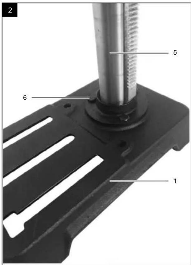
9.1 Installing the column (5) and base plate (1) (Fig. 2)
- Set the base plate foot (1) down on the floor or the workbench.
- Place the column (5) on the base plate (1) so that the holes on the column (5) align with the holes on the base plate (1).
- Screw the three screws (6) to fasten the column (5) into the base plate (1) and tighten them using an open-ended spanner (size 13).
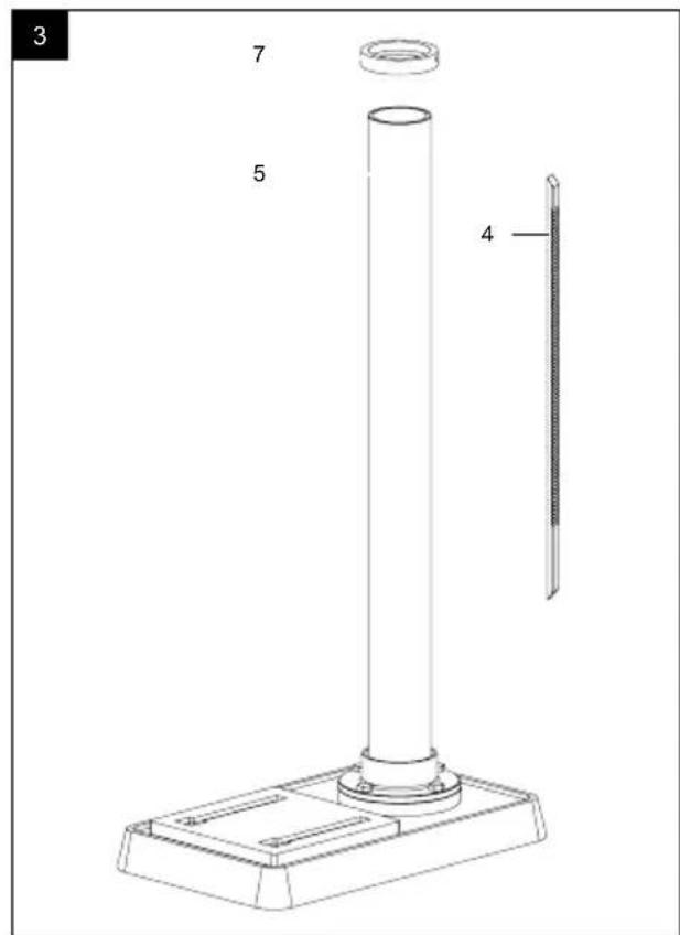
9.2 Removing the toothed rack (4) (Fig. 3)
In order to be able to install your drill, you must first remove the toothed rack (4).
- Use an Allen key (size 3) to remove the ring (7) and pull this off the column (5).
- Now pull the toothed rack (4) out.
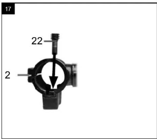
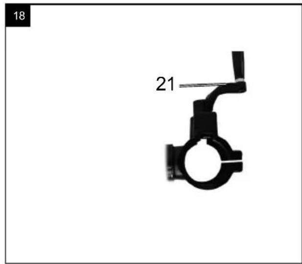
9.3 Pre-installing the drilling table holder (fig. 17+18)
- Push the crank holder (22) through the hole in the drilling table holder (2) from the inside.
- Put the crank handle (21) on the crank holder and use the Allen key to secure the crank handle (3).
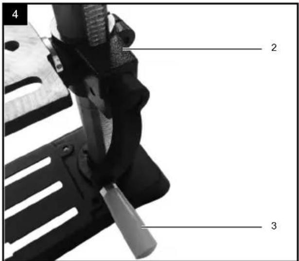
9.4 Installing the drilling table holder (2) (Fig. 4)
- Insert the toothed rack (4) into the groove on the drilling table holder (2).
- Align the toothed rack (4) centrally in relation to the drilling table holder (2).
- When bringing the toothed rack (4) together within the groove, ensure that the tooth meshing between the toothed rack (4) and the drilling table holder (2) is correct.
- Now place the drilling table holder (2) with the toothed rack (4) on the column (5) and guide the toothed rack (4) into the bottom rack guide on the column foot.
- Use the ring (7) to secure the toothed rack (4). Ensure that the toothed rack guide on the ring (7) is pointing downwards. Tighten the integrated grub screw to affix the ring (7).
- Connect the adjustment handle for height adjustment (3) to the drilling table holder's shaft (2) and use a grub screw to secure it.
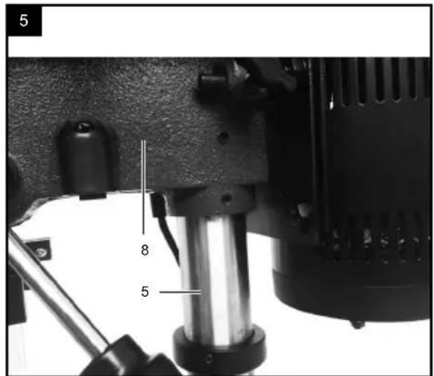
9.5 Installing the machine head (8) and column (5) (Fig. 5)
- Place the machine head (8) on the column (5).
- Align the drill's spindle (33) with the drilling table (18) and the base plate (1).
- Tighten the two grub screws on the side of the machine head (8). Use an Allen key (size 4) for this.
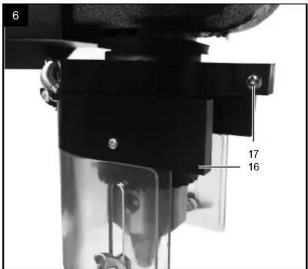
9.6 Installing the chuck guard (16) (Fig. 6)
- Put the chuck guard (16) on the spindle tube.
- Tighten the slotted screw (17).
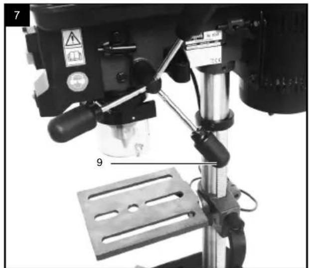
9.7 Installing the handles (9) on the vertical drive's crank (Fig. 7)
- Screw the handles (9) tight in the spindle hub's thread.
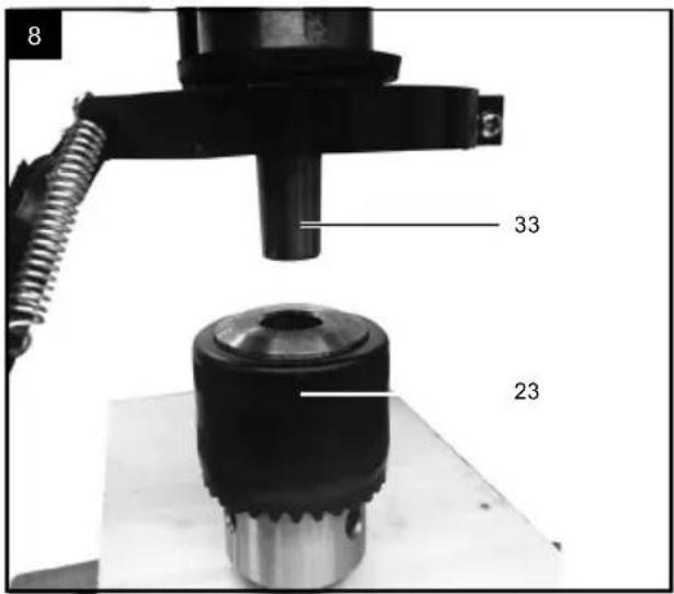
9.8 Installing the sprocket chuck (23) (Fig. 8)
- Clean the conical hole in the sprocket chuck (23) and the spindle cone with a clean piece of fabric. Ensure that no particles of dirt remain on the surface. The smallest amount of contamination on one of the surfaces prevents the sprocket chuck (23) holding properly. This can cause the drill bit to wobble. If the conical hole in the sprocket chuck (23) is extremely contaminated, use a cleaning agent on a clean piece of fabric.
- Push the sprocket chuck (23) onto the spindle nose as far as possible.
- Turn the outer ring on the sprocket chuck (23) counterclockwise (when viewed from above) and open the jaws on the sprocket chuck (23).
- Place a piece of wood on the machine table and lower the spindle (33) until it touches the piece of wood. Press tight so that the chuck is secure.
9.9 Installing the box column drill on the workbench
- Screw the drill tight to a workbench using the holes on the base plate (1) in order to prevent the machine tilting.
- However, for your own safety, a screw connection on a workbench or similar is strongly recommended.
10. Settings
WARNING
All required pre-settings for working properly with your drill have already been made in the factory. Please do not modify anything.
Normal wear and use of the tool can make subsequent adjustment necessary.
WARNING
Always remove the mains plug before carrying out adjustments on the product.
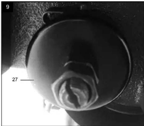
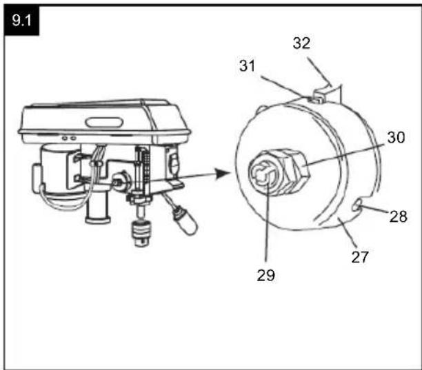
10.1 Setting the spindle return spring (Fig. 9+9.1)
The spindle return spring may have to be set, as it's tension has changed and therefore, the spindle (33) moves back too quickly or too slowly.
- Lower the drilling table (18) for more space to work.
- Work on the left of the drill.
- Insert a screwdriver into the front groove (28) and keep this in position.
- Use an open-ended spanner (size 14) to remove the outer nut (29)
- With the screwdriver still in the groove (28), loosen the inner nut (30) until the notch (31) releases from the hub (32).
ATTENTION: Springs are tensioned!
- Turn the spring cap (27) carefully in an anti-clockwise direction using the screwdriver until you can press the groove (28) into the hub (32).
- Lower the spindle (33) into the lowest position and keep the spring cap (27) in position. Once the spindle (33) moves up and down as you require, re-tighten the inner nut (30).
- If it is too loose, repeat steps 3-5. If it is too tight, repeat step 6 in reverse order.
- Use an open-ended spanner to secure the outer nut (29) against the inner nut (30).
- NOTE: Do not over-turn and do not limit the range of movement of the spindle (33)!
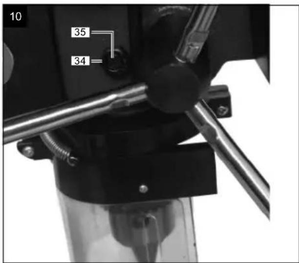
10.2 The axial play for the spindle (33) (Fig. 10)
When the spindle (33) is in the bottom position, turn it manually. If you determine that the play is excessive, proceed as follows:
- Loosen the counternut (34).
- Turn the screw (35) clockwise in order to compensate for the play without impairing the upwards and downwards movement for the spindle (33) (a small amount of play is normal).
- Re-tighten the counternut (34).
11. Commissioning
WARNING
Always make sure the product is fully assembled before commissioning!
WARNING
Danger of injury!
Do not insert the mains plug into the socket until you are ready to use the product.
WARNING
If you are not familiar with this type of machine, obtain advice from a specialist. You must have read and understood the usage and safety information before you work with this product.
11.1 ON/OFF switch (24)
Switching on
-
Insert the mains plug into a properly fused mains socket.
-
Press the "I" button on the on/off switch (24) to switch the product on.
Switching off
-
Press the "0" button on the on/off switch (24) to switch the product off.
-
Wait until the product has come to a standstill.
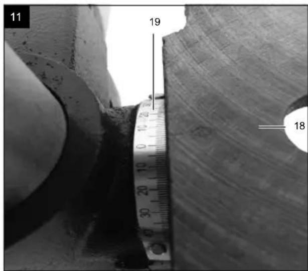
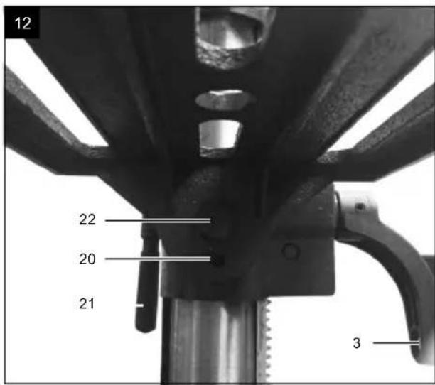
11.2 Swivelling the table (Fig. 11+12)
NOTE: The angle scale (19) is only intended as a rough guideline for angle setting. Suitable protractors must be used for precision work.
-
In order to move the drilling table (18) into the inclined position, use a size 19 open-ended spanner to undo the clamping screw (22) and remove the screw (20) that is used for 90^ fixing with the aid of an open-ended spanner size 10.
-
Use the angle scale (19) to set the required angle.
-
Re-tighten the clamping screw (22).
11.3 Setting the table height (Fig. 11+12)
-
Loosen the clamping handle for height adjustment (21).
-
Set the drilling table (18) to the required height by cranking the adjustment handle for height adjustment (3).
-
Re-tighten the clamping handle for height adjustment (21).
NOTE:
We recommend setting the table height so that the tip of the drill bit is just above the workpiece.
11.4 Handling the sprocket chuck (23)
Your bench drill is equipped with a sprocket chuck (23).
To insert a drill, proceed as follows:
-
First fold up the chuck guard (16).
-
Insert the drill.
- Tighten the sprocket chuck (23) with the supplied chuck key (26).
- Retighten the chuck key (26).
- Ensure that the clamped tools are firmly secured.
Clamping the drill
Always ensure that the mains plug is removed when changing the tool.
Only cylindrical tools with the specified maximum shaft diameter are permitted to be clamped in the sprocket chuck (23). Only use faultless and sharp tools. Do not use any tools with damaged shafts or that are deformed or damaged in any other way.
Only use accessories and additional equipment that are specified in the operating manual or that have been approved by the manufacturer.
- Insert the drill bit deeply enough into the sprocket chuck (23) that the chuck's jaws can grip in an optimum manner. (Ensure that the jaws do not touch the drill bit's spirals on small drill bits).
- Ensure that the drill bit is centred in the sprocket chuck (23).
- Use the chuck key (26) to tighten the chuck sufficiently so that the drill bit cannot slip when working.
WARNING: Do not leave the chuck key (26) inserted.
Danger of injury due to the chuck key (26) ejecting.
Changing the sprocket chuck (23)
Turn the outer ring on the sprocket chuck (23) as far as possible in an counterclockwise direction.
Tap the sprocket chuck (23) gently with a wooden or rubber hammer. Hold the chuck with the other hand when it slides off the spindle (33).
11.5 Working speeds
Ensure that the speed is correct when drilling. This depends on the drill bit diameter and the material.
The list below helps you to choose speeds for the various materials.
The specified speeds are only guideline values.
| ø of drill | Cast iron | Steel | Iron | Alu-minium | Bronze |
| 3 25 | 50 1600 | 2230 95 | 00 8000 | ||
| 4 19 | 00 1200 | 1680 72 | 00 6000 | ||
| 5 15 | 30 955 | 1340 570 | 0 4800 | ||
| 6 12 | 70 800 | 1100 | 4800 | 4000 | |
| 7 10 | 90 680 | 960 | 4100 34 | 00 | |
| 8 | 960 | 600 840 | 3600 3000 | ||
| 9 | 850 | 530 740 | 3200 2650 | ||
| 10 76 | 480 | 670 | 2860 | 2400 | |
| 11 | 700 | 435 | 610 | 2600 | 2170 |
| 12 640 | 400 | 560 | 2400 | 2000 | |
| 13 590 | 370 | 515 | 2200 | 1840 | |
| 14 545 | 340 | 480 | 2000 | 1700 | |
| 16 480 | 300 | 420 | 1800 | 1500 |
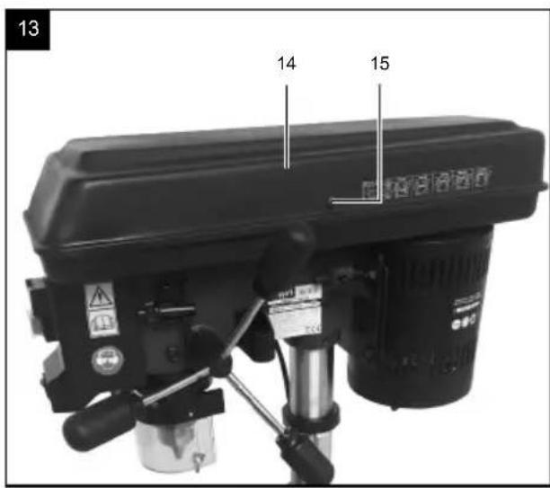
Setting the speed and V-belt tension (Fig. 13 and 13.1) WARNING
Always unplug the mains plug before opening the cover. Always wait until the machine has come to a complete standstill prior to performing maintenance / setting work (danger of injury)! Never run the drill when the V-belt cover is open. Never reach into the V-belt while it is running.
You can set various spindle speeds on your box column drill:
- Once you have switched the product off, you can open the belt guard (14) by undoing the locking screw (15). All adjustment options for the spindle speed are available on the machine's belt guard (14).
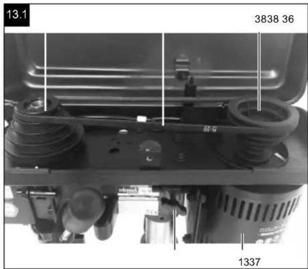
- Slacken the drive belt (36) on the right of the machine head (8) by undoing the wing screw (37). Pull the right of the motor (13) slightly towards the spindle (33) in order to slacken the drive belt (36)
- Place the drive belt (36) around the corresponding pulleys (38).
- Press the right of the motor (13) backwards in order to tension the drive belt (36) again.
- Re-tighten the wing screw (37). The drive belt (36) should have around 13 mm of play when you press it together in the middle.
- Close the belt guard (14) and tighten the locking screw (15).
- If the drive belt (36) slips during operation, re-adjust the belt tension.
ATTENTION:
The pulleys (38) on the opposite side must always be used. If pulleys (38) at a different height are used, the drive belt (36) will be destroyed.
NOTE: Safety switch
If you wish to set the speed, you must open the cover. In order to prevent the danger of injury, the safety switch switches the drill off automatically.
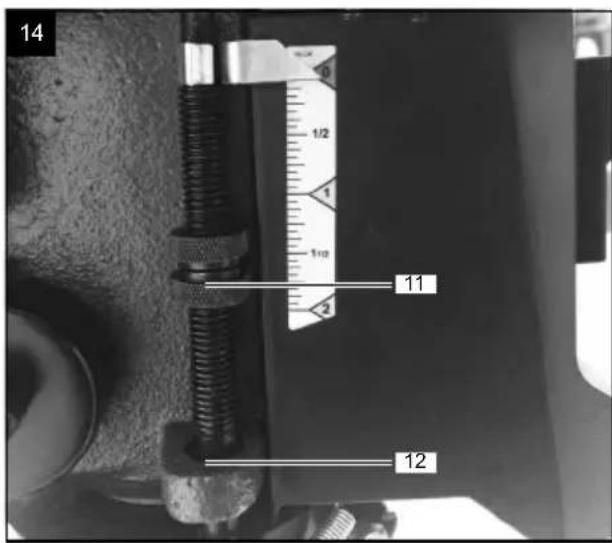
11.6 Depth stop (10) (Fig. 14)
NOTE:
When the clamping device is in the top position, the drill bit's tip must be just slightly above the top of the workpiece.
The depth stop (10) enables the drilling depth to be limited:
- Set the desired drilling depth.
- Screw it on tightly against the lower stop (12) using the knurled nuts (11).
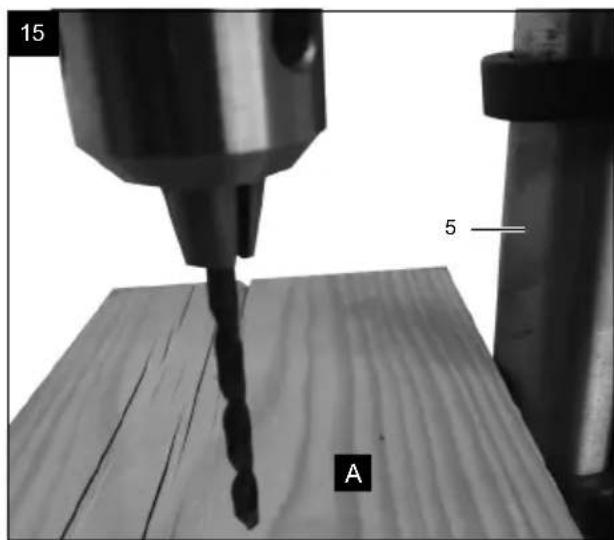
11.7 Positioning the workpiece (Fig. 15)
Always place a base (A) (e.g. wood) between the table and workpiece. This prevents the rear of the workpiece splitting or breaking when drilling through.
In order to prevent the base turning uncontrollably, lean it against the left of the column (5) as illustrated.
WARNING
If the workpiece or the base is not long enough for this, clamp it to the table, as otherwise, serious injuries may occur.
NOTE
Use the machine vice (accessory) for smaller workpieces that cannot be clamped to the table.
The vice must be clamped or screwed to the table in order to prevent injuries due to rotating workpieces or the vice, and to prevent destroying the tool.
11.8 Drilling a hole
- Use a punch or a sharp nail to mark the location to be drilled on the workpiece.
- Before you switch the drill on, lower the drill bit onto the workpiece and centre it over the location to be drilled.
- Switch the machine on and press the drill bit gently onto the workpiece so that it can cut cleanly.
If there is insufficient downward pressure, there is the risk that the drill bit will become hot.
If there is excessive downward pressure, there is the risk that the motor (13) will block, the V-belt or the drill bit will slip, the workpiece will come loose or the drill bit will break.
When drilling metal, you may have to cool the drill bit with suitable fluid.
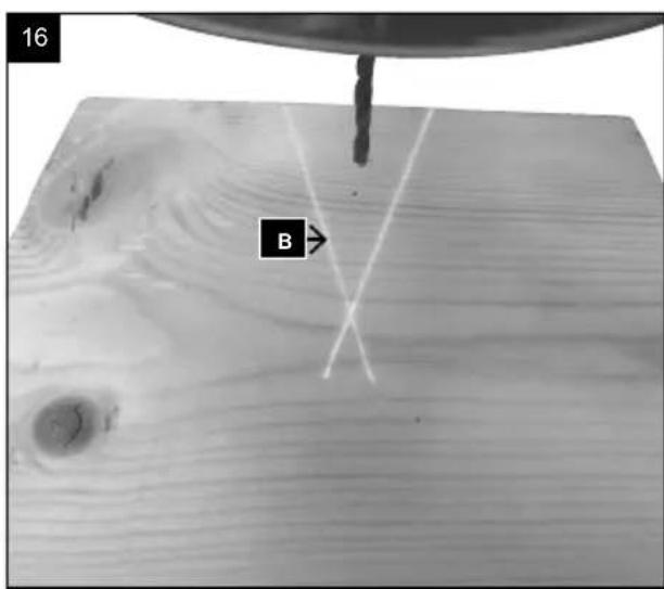
11.9 Working with the laser (Fig. 16)
- Switch the laser light on with the laser On/Off switch (25).
- Place the marked hole in the fixed point (B) of the laser.
- Put the drill in and drill a hole.
11.10 Countersinking and centre drilling
You can also use this tabletop drill for countersinking or centre drilling.
Note that countersinking must be performed at the lowest speed while a high speed is required for centre drilling.
11.11 Machining wood
Note that suitable dust extraction must be used when machining wood, as wood dust can be harmful to health.
Wear a suitable dust protection mask when performing work that generates dust.
12. Electrical connection
The electrical motor installed is connected and ready for operation. The connection complies with the applicable VDE and DIN provisions.
The customer's mains connection as well as the extension cable used must also comply with these regulations.
Damaged electrical connection cables
The insulation on electrical connection cables is often damaged.
This may have the following causes:
- Pressure points, where connection cables are passed through windows or doors.
- Kinks where the connection cable has been improperly fastened or routed.
- Places where the connection cables have been cut due to being driven over.
Insulation damage due to being ripped out of the wall outlet. - Cracks due to the insulation ageing.
Such damaged electrical connection cables must not be used and are life-threatening due to insulation damage.
Check the electrical connection cables for damage regularly. Ensure that the connection cables are disconnected from electrical power when checking for damage.
Electrical connection cables must comply with the applicable VDE and DIN provisions. Only use connection cables of the same designation.
The printing of the type designation on the connection cable is mandatory.
AC motor
The mains voltage must be 230 volts/50 Hz.
- Extension cables up to 25m long must have a cross section of 1.5 square millimetres, and those over 25m long must have a cross section of at least 2.5 square millimetres.
The mains power connection is protected with a 16A slow-blow fuse.
Connection type Y
If it is necessary to replace the mains connection cable, this must be done by the manufacturer or their representative to avoid safety hazards.
13. Transport
- To transport the product, disconnect it from the power supply.
- Only lift the product by the belt box and the frame plate. Never lift the product by the safety devices or the adjustment handles.
- When transporting the product, be aware of the weight distribution: The product is top-heavy. Therefore, only transport the machine lying down and secured on a suitable fixture.
14. Cleaning and maintenance
WARNING
Have maintenance and repair tasks that are not described in this operating manual, carried out by a specialist workshop. Use only original spare parts.
WARNING
Improper cleaning or maintenance work can cause injuries!
WARNING
The product may start unexpectedly and cause injuries and burns during cleaning, repair and maintenance work.
- Switch the product off.
- Pull out the mains plug.
- Allow the product to cool down.
- Remove the tool attachment.
14.1 General information
Each time before using the product, check it for obvious defects such as loose, worn or damaged parts, or that screws or other parts are tight.
- Replace damaged parts.
14.2 Cleaning
- Do not use cleaning agents or solvents. Chemical substances could damage the plastic parts of the product. Never clean the product under running water.
- Clean the product thoroughly after each use.
- Clean the ventilation holes and the surface of the product with a soft brush or cloth.
- Remove swarf, dust and dirt with a vacuum cleaner if necessary.
14.3 Maintenance
All ball bearings are greased in the factory so that re-greasing is not required. Lubricate all grooves in the spindle (33) and the toothed rack (4) regularly, as well as all moving parts. Do not allow any lubricants to come into contact with switches, V-belts, drive pulleys and drill lifting arms.
Lubricating the drive
- Move the axle down.
- Insert the grease into the spindle (33) from above below the top cover).
- Move the axle up and down a few times.
Lubricating the toothed rack
- Move the axle down.
- Grease the outer surface of the axle.
15. Repair & ordering spare parts
After repairs or maintenance, make sure that all safety-related parts are installed and are in perfect condition. All parts which may cause injury must be kept where they are inaccessible to children or others.
Attention: According to the German Product Liability Act, no liability is accepted for damage caused by improper repairs or by not using original spare parts.
Such work should be performed by a customer service centre or an authorised specialist. The same applies to accessory parts.
Connections and repairs
Connections and repair work on the electrical equipment may only be carried out by electricians.
Please provide the following information in the event of any queries:
Type of current for the motor
Machine data - type plate
- Motor data - type plate
Important note in the case of repairs:
For return delivery of the product for repair, please ensure for safety reasons that it is free of oil and fuel when it is sent to the service centre
Ordering spare parts
Please provide the following information when ordering spare parts:
- Model designation
- Item number
- Type plate data
Spare parts / accessories Article no.:
Pulley 3906806051
V-belt 3906806035
Handle 4906807008
Chuck with chuck key 3906807022
Drive shaft 4906807003
Laser complete 4906807004
Service information
With this product, it is necessary to note that the following parts are subject to natural or usage-related wear, or that the following parts are required as consumables.
Wearing parts*: Carbon brushes, V-belts, batteries, drill bits
- may not be included in the scope of delivery!
Spare parts and accessories can be obtained from our Service Centre. To do this, scan the QR code on the front page.
16. Storage
- Store the product and its accessories in a dark, dry and frost-free place that is inaccessible to children.
The optimum storage temperature is between 5 and 30^ - Store the power tool in its original packaging.
- Cover the power tool to protect it from dust or moisture.
- Store the operating instructions with the power tool.
17. Disposal and recycling
Notes for packaging


The packaging materials are recyclable. Please dispose of packaging in an environmentally friendly manner.
Notes on the electrical and electronic equipment act (ElektroG)
Waste electrical and electronic equipment does not belong in household waste, but must be collected and disposed of separately!
- Used batteries or rechargeable batteries that are not installed permanently in the old device must be removed non-destructively before disposal! Their disposal is regulated by the battery act.
18. Troubleshooting
-
Owners or users of electrical and electronic devices are legally obliged to return them after use.
-
The end user is responsible for deleting their personal data from the old device being disposed of!
The symbol of the crossed-out dustbin means that waste electrical and electronic equipment must not be disposed of with household waste.
-
Waste electrical and electronic equipment can be handed in free of charge at the following places:
-
Public disposal or collection points (e.g. municipal works yards)
-
Points of sale of electrical appliances (stationary and online), provided that dealers are obliged to take them back or offer to do so voluntarily.
-
Up to three waste electrical devices per type of device, with an edge length of no more than 25 centimetres, can be returned free of charge to the manufacturer without prior purchase of a new device from the manufacturer or taken to another authorised collection point in your vicinity.
Further supplementary take-back conditions of the manufacturers and distributors can be obtained from the respective customer service.
- If the manufacturer delivers a new electrical device to a private household, the manufacturer can arrange for the free collection of the old electrical device upon request from the end user. Please contact the manufacturer's customer service for this.
These statements only apply to devices installed and sold in the countries of the European Union and which are subject to the European Directive 2012/19/EU. In countries outside the European Union, different regulations may apply to the disposal of waste electrical and electronic equipment.
WARNING: Always switch the machine off and pull the plug out of the socket prior to troubleshooting.
| Fault Possible cause Remedy | ||
| The axle moves back into its starting position too quickly or too slowly | Incorrect setting of the spring pre-tension | Set the pre-tension; see “Setting the spindle return spring” |
| The chuck always comes loose from the spindle despite continued fastening | Dirt, grease or oil on the spindle or the inside of the chuck | Use a household cleaning agent to clean the surface of the spindle and the sprocket chuck, see “Installing the sprocket chuck” |
| High noise level during operation | Incorrect V-belt tension Set the V-belt tension anew; see “Setting the speed and V-belt tension” | |
| Spindle too dry | Test the spindle; see “Maintenance” | |
| The pulley on the spindle is loose Check that the nuts on the pulley are tight and re-tighten if necessary | ||
| The pulley on the motor is loose Tighten the adjusting screw on the pulley on the motor | ||
| The wood splits on the drill bit's outlet opening | There is no suitable base underneath the workpiece | Use a suitable base; see “Positioning the workpiece” |
| The workpiece is pulled out of your hand | There is no suitable base underneath the workpiece | Underpin the workpiece |
| Workpiece not fastened sufficiently Fasten the workpiece | ||
| The drill bit wears out Incorect speed. Change the speed; see “Setting the speed and V-belt tension” | ||
| No chips come out of the hole Move the drill bit out of the hole regularly in order to pull the chips out | ||
| The drill bit is blunt. Sharpen the drill | ||
| Insufficient downward pressure Increase the downward pressure | ||
| The drill bit slips or the hole is not round | Hard spots in the wood Sharpen the drill | |
| The length and angle of the drill bit is different | Sharpen the drill | |
| The drill bit is bent. Replace the drill bit | ||
| The drill bit gets stuck in the workpiece | The workpiece and drill bit are twisted or the downward pressure is too great | Place something under the workpiece or fasten it; see “Positioning the workpiece” |
| Insufficient V-belt tension Set the V-belt tension; see “Setting the speed and V-belt tension” | ||
| The drill bit drifts and vibrates excessively | The drill bit is bent Use a straight drill bit | |
| The spindle bearing is worn excessively | Replace the spindle bearing | |
| The drill bit is not clamped centrally in the chuck | Check the centring; see “Clamping the drill” | |
| The chuck is not fastened correctly. | Fasten the chuck correctly, see “Handling the sprocket chuck” | |
Günzburger Straße 69
14.1 Üldised juhised
Viktig information for reparation:
PAS P! Fjederen star under spanding!
Smoring at tandstangen
MERKNAD: Sikkerhetsbryter
Hvis du onsker a stille inn hastigheten ma du apne dekslet. For a unnga skadfare vil boremaskinen automatisk bl slatt av med sikkerhetsbryteren.
11.6 Dybdeanslag (10) (fig. 14)
MERKNAD:
11.11 Trebearbeiding
Ipon3bOndTeJIr He Hocn OTROBOPHOCT 3a uetn, npHcHEnoT He npabunHa ynoTppe6a nn He npabunHo 06cnyXbaHe.
06aCHeHHe Ha cHrHaHnHte dymu B pBkoBOcTBOTO 3a ekCnIloaTaun
ONACHOCT
CnHaHa Dyma 3a o6o3HaVaBaHe Ha HenocpeDCTBeHO onaCha cnTyauu, KOrTo, aKO He 6bJe n36erHata, ue DOBeDe Do CMBpT INN cepNo3HO HapaHbAhe.
PENEYNPEXDEHNE
CnHaHa Dyma 3a obO3HaayabaHe Ha Bb3MOxHa onacha CnTuayu, KOrTo, aKO He 6bJe H36erHaT, MoKe Da IOBeDe Do CmBpT nH cepNo3Ho HapaRaBaHe.
BNAFOPA3YMNE
CnHaHa Dyma 3a 06o3HaayBaHe Ha noteHuaHNO onaCha CHTyaun, KOTo, aKO He 6bJe N36eHaT, MoKe Da DoBeDe Do JeKn Hn cpeHN HapaHbAHn.
BHIMAHNE
CnHaHa Dyma 3a o6o3NaUbaHe Ha noteHuaHNo onacHa cnTyauu, KOrTo, aKo He 6bIe n36erHata, MoKe Da DoBeDe Do nobpeXdaHe Ha npOdykTa Hnn NMyueCTBeHN uetn.
5. 06uynka3aHna 3a 6e3oNaCHOCT
06u yka3aHnna 3a 6e3oNaChocT 3a eNeKtpnueckn HnCTpymEnTH
PPEyPExEHE! PpOeTeBcNk yka3aHn 3a 6e3oNaChocT, HNCTpyKuH, NIOcTaCuHn TExHueckn DaHH, PpeOCTaBeHn C To3n eJekTpueckn HNCTpyMeHT. PpOnyckn npn cna3BaHeTo HA INHCTpyKuHTE NO-DOy MoRat Da IOBeDaT DO TOKOB yAp, NoXap n/nn TeKk HapaHbAHn.
3ana3eTe BCnUk yka3aHn 3a 6e3onacHocT nH-ctpyKuN 3a 6bJeun cnpabKn.
N3noJ3BaHOTOByka3aHnraTa 3a6e3oNaChOCTNoHrTne "eJeKTPnueckn INHCTpyMeHT" ce OTHacrdo 3axpaHbAHn OT MPexKaTaeJeKTPnueckn INHCTpyMeHTn (C MPexKOB npOBODnK) nIIN Do 3axpaHbAHc akyMylatop eJeKTPnueckn INHCTpyMeHTn (6e3 MPexKOB npOBODnK).
1) Be3onachocHT Ha pa60THOTo MrcTo
a) NopdIbpxaIte pa6oTHOTcMЯCTO YHCTO INdo6peocBeTeHO. Be3npAdbKbT nIN HeOCBeteHNTE pa6oTHN MecTa MORaT Da IOBeDaT Do 3IO-NOJyKn.
b) He pa6oTeTe c eJektpnueckn HnHcTpymeHT Bbb B3pnuBOONacHa CpeDa, B KOrTo NMa 3anaJIIMN TeuHOCTn, Ra3OBe nIIN npaxOBe. EJeKtpnYeCKnTe IHcTpymeHTN Cb3dAbaT NCKpn, KOITOMOrat Da BB3PnAmEHeT npaxa IIn NapTe.
c)ДрькTe Deua npyr nIua daneu no BpeMe Ha n3noJ3BaHeTo Ha eIeKtpnueckn HnCTpyMeHT.Пп pa3ceiBaHcMoXeTe da n3ry6nte KOHTpOJI Bbpxy eIeKtpnueckn INHCTpyMeHT.
2) Be3onacnoct npa6oTa c eJektpueeckn ToK
a) ΜεπceNBt Ha eIeKtpnueckn HhctpymEnr Tp86Ba Da OTROBapra Ha KOHTAKTa. ΜεncenbT He 6nBa Da ce npomeH No HnKaKBb NaunH. He n3noJ3BaIte aAanTepn HcpeJI 3aeJHO cbC 3a3eMeH eIeKtpnueckn HhctpymEnr. HenpoMeHen IeNCEJI N NOxOJaU KONTAKn HamaJI-Bat pNCKa OT TKOB ynap.
b) 1368raBaiTe TeneceH KOHTAK Cbc 3a3eMeHN NOBbpXHOCTN KATO Tpb6n, OTONNTENH ype- dN, cyprHn XnaDnHnC. CbIeCTByBa NOBiu- weH pNCK OT TokOB ydap, koraTo TAnoto Bne e 3a3emeHo.
c) PanaTe eNEKtpnuecknte HNCTpyMeHT O T bXkN Bnara. IPOHnKBaHeTo Ha BOda B eNEKTPnuecknna IHCTpyMeHT yBEnuHaBa PNCKa OT TOKOB yIap.
d) He n3no3BaIte Ka6eHa He no npedHa3HaueHne, 3a HocHe nn 3akaayane Ha eNeKtpnueCKn HNCTpymENT nn 3a N3DbPnBaHe Ha JeenCeNa ot KOHTa. Pa3eTe Ka6eHa ot ropeuHa, MacNo, OCTpnpb6oBe nn DvNxce ci actn Ha ypeDa. POBpeHn nn ycKaHN Ka6eN yBENNuBaAT pncA OT TKOB ynap.
e) Korato pa6oTnte c eJeKtpnueckn HnCtpy-MENT Ha OTkpTO, n3noN3BaIte caMo yDbJxN-TeHN Ka6eH, KOInTo CbIoo ca NODXODAa 3a ynotpe6a Ha OTkpTO. IV3noN3BaHeTo Ha NOxOJa, 3a ynotpe6a Ha OTkpTO yDbJnxTeJIeH Ka6eH hAmajraBa pNcKa oT TOKOB yIap.
f) Korato ynotpe6ata Ha eJektpnueckn H-CTpymENT BbB BnaXHa cpeHa He Moxe Da 6bde n36erHata, n3noJ3BaTe DeΦeKTHOTOKOBa 3aunTa. N3noJ3BaHTo Ha deΦeKTHOTOKOBa 3aunTa HamaJIyBa pNcKa O T TOKOB yap.
3) Be3onacHOCT Ha Xopata
a)БbTe BHMateHn,O6pBuaTe BHMaHHe Ha TOBa,KoETO npaBHT,N NOxoxdaI-Te pa3ymHO KbM pa6oTata C eNEKtpueckn HHcTpymENT. He n3non3BaHTe eNEKtpueckn HHcTpymENTu,akoCTe ymopeHN NnIOB bHnJHHeTO Ha HapKOTU,anKOxOJ NnMeDnKa-MeHTn.MoMeHT HeBHMaHHe npu N3noJ3BaHoTo Ha eNEKtpueckn HHcTpymENT MoKe da DOBeDe Do cepNo3Hn HapaHraHn.
b) Hocete NnHn npedna3n CpeCTBa n BnHa r 3aunTHn OuHa. HocheTo Ha JnHn npedna3n CpeCTBa, KATO npotnbopaxoBA macka, npedna3- Hn obyBkn, KOITO He ce XNb3rat, npedna3Ha kacka IIN 3aunTa 3a cnlyxa, cnped Bnda n ynoTpe6ata Ha eNeKtpueckn INCTpyMeHT, HamaIra Ba pCKa OT HapaHraBaHn.
c) N368BaTe HeBONHO BKNIOUBAHe. YBepeTe Ce, Ye eNEKtpuecknT HNCTpyMeHT e N3KIOHey, npEi Da rO CBbPxKeTe KbM eNEKtpo3axpaHbaHeTo n/nnn aKymyIaTopa, npEi Da ro B3eMeTe nn HocHTe. Ako npu HOceHTo Ha eNEKtpuecknI HNCTpyMeHT dbpXKeTe pbcTa cn Bbpxy npekcbBaayn CbPKeTe KbM eNEKtpo3axpaHbaHeTo BKNIOUeH eNEKtpueckn HNCTpyMeHT, TOBa MoKe Da DOBede Do 3JNOJNYKn.
d) OtcpaheTe HcTpymeHTte 3a Hactpoika nnraeunite KIOOObE, npedn da BKNIOUHTe eJeKtpnueckna HcTpymeHT. HcTpymeHT nn KIOU, HAMpaA, ce BBB BbptTua ce qact OT ype-da, MOKe Da DoBeDe Do HapaHbAHn.
e) N368BaIte HnpaBnHa cToKa Ha TAnTo. OcnrypeTe cn cTaBnEn cToeK n NoctOaHNo na3e paBHOBeCne. TaKa MoXeTe Da KOHTpOni-pate eJekTpueckn IHNCTpymEnT no-dOppe npn HeoayakBaHn CNTyaun.
f) Hocete noxoada o6neKn. He hocete u npokn dpexn nn ykpaenHn. Dpbjxt Kocata, 6neKIOTo n pbkauNTe cn daJeY OT DBNKe- uI ce qactn. Wnpokn dpexn, ykpaenHn nn Dblnn KOCMORAT Da 6bDat 3axBaHaTn OT DBN- XeUc CE qactn.
g) Korato Morat Da 6bDaT MOHTnpaHn npaxo3-CmykBaun npaxoynaBua yctpoNCTBa, yBepeTe ce, ye Te ca Cbbp3aHn Hce n3non3Bat npabnHNo.N3noN3BaHeTo Ha npaxoN3cMykBauo yctpOJCTBO MOKe Da HamaJIb BpeDInTe 3a 3dpaBeto nopadn npax.
h) He ce noДаBaTe Ha faIshnBTo yBCTBO 3a 6e3onacHocT n He npEne6perBaTe npaBnJaTa 3a 6e3onacHocT npn pa6Ota C eJekTpuecknte HnCtpyMeHTn, DOpn aKo cNeM MHorokpaTHata nM yNoTpe6a MncJIte Ye rN No3HaBaTe Do6pe. He6pexKnTe DeIcTBnMa MoRat Da doBeDaT Do TeKKn TeJeCHn NOpeDN B pAMKIne Ha qactn OT cekyHdata.
4) YnOtpe6a n 6opabHe c eJneKtpnueckn HNCTpyMeHT
a) He npetobapBaTe ypea. 3nnon3BaTe no-dxodyua 3a Baata pa6ota eNeKtpueeckn HCTpyMeH. C nOxODyua eNeKtpueeckn HCTpyMeT pa6oTne no-do6pe n no-cnrypHo B dnaana30Ha ha pa6oTHnte My xapaKtepuCTnKn.
b) He n3noJ3BaIte eJekTpueeCKn HNCTpyMeHT, cnTo npekbcBaue noBpeDeH. EJeKtpueeCKn HNCTpyMeHT, KOTo He MoKe Da Ce BKNIOUBA nn N3KnIOUba, e OnaceH n Tp6Ba da 6bnde peMOHTnpaH.
c) N3BaTe ΣeCenJa OT KOHTaKTa N/INN IN3Ba-DeTe CMeHЯEEMn AkyMylaTOp, Ppei Da N3-BbPWBate HAcTpOienNo ypeDa, Da CMeHrTe Yactn Ha pa60THnIHCTpyMeHr NIn Da OCTaBtE eNeKtpuYeCKn IHCTpyMeHr Ta3n MpaKa 3a 6e3oNaChoc TpeDToBpTaYBa HeymuJIeHOTo BKNIOUBAHe HA INCHTPyMeHrA.
d) CbXpaHbAte He3n3oN3BaHnte eNeKtpn-yeckn HhctpyMeHTn Ha HeDocTbHNO 3a Dea Macto. He no3BolraBaiTe eNeKtpnueecknT nHcTpymeHT da 6bJe n3no3BaH ot Nua, KOtO He ca 3aNo3HaTu C Hero mHe ca npOeyI Te3n HhCTpyKcII. EneKtpnueecknte HhctpyMeHTn ca Onachn, aKO ce n3no3BaT OT HeONNTn Nua.
e) PoiDJIbPkaIte eNeKTpNueCKNte HNCTpyMeHTn pa6OTHNAHCTpyMeHT rpnXIINo. IpOBepaBaiTe daI N DBNXeIe NTce Ce aactn FyHKUHOHPaT 6ezynpeuHO n He 3aJxDaT, daI N HMa CuyneH nn Taka NOBpeHn Yactn, ye Da HapUwABat FyHKUHOHpaHTo Ha eNEKTPNueCKN INCTpyMeHT. IOBpeHNTe Yactn cJeBa Da 6bDat peMOHTnpAHn IpEdu N3NOJ3BaHeTO Ha eNEKTPNueCKN INCTpyMeHT. MHoro 3JIoNOLyKn ca npuHHeH NOT LoIO NODbPxAHN eNEKTPNueCKN INCTpyMeHTn.
f) Pndbpxknte pekeuTe uHcTpymEnHaTo-ueHN uNCTn. rPnxKnBO noDbpxKaHnTe pekeu HcTpymEnC octpnpekeu np b6oBe ce 3aknHBaT NO-MANKO n Ce BOyT NO-JeCHO.
g) N3noJ3BaIte eJektpnueckn HNcTpymeHT, npHnAdJexKHOCTnTe, pa6OTnTe HNcTpymeHTn T.H. CbflacHo HAcToaHnTe HNcTpYkCm. PpTOBa B3emaIte NOd BHMaHHe yCNoBnTa Ha pa6Ota I DeiCTBnETo, KoEt O Tpr6Ba Da ce N3BbpS. Ynotpe6ata Ha eJektpnueckn HNcTpymeHTn 3a pa3JIuHn OT IppeDbIeHnTe PpNJIOxHeHn MOKe Da IOBeDe Do ONaCHn CNTyaCm.
h) PanaTe DpBxKnTe n TexHnTe NOBbpxHOCTn cyXn, uNCTn n 6e3 MacNo n rpec. XIb3raBnTe dpBXKn n TexHnTe NOBbpxHOCTn He nO3BOJIaBat 6e3oNa cha pa60Ta n KOHTpon Ha eNeKtpuYeCKn INHCTpyMeHT B HEnpeDnDuEH CuTyaUuN.
5) CepBn3
a) Bb3naraTe peMOHT no Baunie enektpn-ueckn nHcTpymeHT caMo Ha KBaunuucnpaHn cneunanctn u camo C opurnaHn peepBn qactn. Taka ce rapaHTnpa, ye 6e3onacHocTt ha eJektpnueeckn nHcTpymeHT ue ce 3ana3n.
Yka3aHnna 3a6e3oNaChocT 3a 6OpMaunHH
a) BopmaunHaTa Tp6Ba Da 6bJe Do6pe 3akpe- neha. HnpabnHno 3akpeneHaTb 6opmaunHa MOKe Da Ce NOMeCTN INI INpeo6bpHe, KOeTo da IOBeDe Do HapaHbaHna.
b) 06pa6oTBaHnT DeTaJn Tp86Ba Da ce 3aterHe nn 3akpen KbM onopata 3a Detai. He npo- 6BbAte DeTaN, KOtO ca TBbpDe MaKn, 3a da 6bDat cnpyhno Da 6bDat 3aterHaTn. DbP- XaHeTo Ha 6pa6oTBaHnI DeTaN C pbKa MoKe Da DOBeDe Do HapaHraBaHn.
c) He Hocete pBkabu. PbkabuNTe MORaT da 6bDat 3axBaHATN OT BbpTAAUITE ce qactn Ha MaunHATA NIN CTbPROTNHTE OT npoNBaHTo, KOETO Da DOBeDe Do HapaHBAHn.
d)ДрьхTe pьцete cn daneluy OT 30HaTа Ha npo-6nBaHe,doKaTo eIeKtpnuecknT nHcTpymeTppa6Ot. KoHTaKTbT C BbPTaunite ce qactn HaMaUnHata NIn CTbPOTnHnte OT npo6nBaHetoMOKe da DOBeDe Do HapaHbaHna.
e) CBpeIIOBbUHnT HNCTpymENT Tp8Ba Da ce 3aBbptn, npEi Da ro HacOHTe KbM o6pa-6OTBaHnA DetaII. B npOTuBeH cnyaH cbpeI IOBbUHnT HNCTpymENT MoKe Da ce 3aKaun I NO To3n HaunHa pEdu3BnKa HeoayKBAHO DnJXeHne Ha o6pa6OTBaHnA DetaII N Da npuHH HapAHyBaHn.
f) Ako CBpeIIOBbHnIHT HnCTpyMeHT ce 6NoKnpa, cnpTe Da HaTnCKaTe HaOJy N n3KnIOUeTe eJeKTPnueckn I nCtpyMeHT. OTKPnTe n ot-ctpaHete npuHHata 3a 6NoKpHaHeTo. BNoKpHaHTo MoKe Da IOBeE Do HeoayKaHo DnIXKeHne Ha o6pa6OTBaHnI DeTaII N do HapaHraBaHnI.
g) N36yBaTe DbJrnte CtpxKu OT npo6nBaHe, KaTO peoBHO npeKbcBaTe HaTncka HADOny. OcTpne ctpxKu MORa Tda ce 3annetat n da doBeDaT DO HapaHraHn.
h) HnKora He OTCpaHbAte CtpyKNTe ot 30- hata Ha npoNBaHe,doKaTo eNeKTPnuCeKNrT nHCTpyMeHT pa6OTn.3a Da oTcpanTe ctpyK- Knte,OTdaneyeTe CBpeDIOBbUHNr INHCTpyMeHT OT 6pa6OtBaHHra DeTaII, N3KnIOyTe eNEKTPnuCeKNr INHCTpyMeHT rTO n3uKaAitde Ta cnpe. N3non3BaAte NOMOuHn CpeDCTBa, KaTO YETKa HJN KyKa,3a Da OTcpanHTe CTbPROTHn- Te.KoHTaKTbT C BbpTAreIte ce qactn Ha MaunHata Hn CTbPROTHnTE OT npoNBaHeTo MOKe da DOBeDe Do HapaHbAHn.
i) DonyctHmnte o6opOTn Ha npncTbKaTa Tp8Ba Da ca Nohe ToIkoBA BnCOKn, KOJIKOTo caNoocOHeHte BbpyeJeKtpnueckn HnCTpyMeHT MaKcHMaHn O6opOTn. PpuHaJneXHoCTN, KOnTO ce BbPTrno-6bp30 OT DonyCTHMOTO, MORa Ta Ce pa3dpoBt n pa3JeTt HacTpaHn.
BHIMAHNE:Ia3epHoIbYeHne
He rneJaTe B Ibua
Janaep KnaC 2
PanaTe ce6e cn n OkoJHoCTTa ot 3JnoJonyKn Ype3 noJxoJaun npedna3Hn Mepkn!
HeIpeaTe C He3aUHTeH OOn DnpeKTHO KbM Ja- 3epHnaJIbH.
-
HnKora He rneJaTe dIpeKTHO B TpaEKTopraHa nla.
-
Hnkora He HacooyBaIte Ia3epHnIbIy KbM Otpa3raBau nIOBbpXHOCTN, Xopa IIIN JxIBOTHN. DOpn I na3epen IbUc MaIIKa MOUHOCT MOKe Da IpruHH yBpeKdAHe Ha OHTe.
BJIAGOPA3YMNE
Ako ce n3nBnHbAT pa3nUHN OT NOCOeHNTe Tk npoecdypn, TOBa MoKe Da DOBeDe Do OnaCHO n3- JaraHe Ha IbyeHne.
- Hnkora He OTbaprTe Ia3epnMaMyI. MoKe da ce CTurHe Do HeOyakBaHO 3NaIarHe Ha NbYeHne.
Ako npodykTBt Hma da ce n3noJ3Ba IbIro BpeMe, 6aTeepnte Tp6Ba Da 6bDat N3BaDeHn. - Na3epbT He 6uBa da ce noDmeHa c na3ep ot npyr TIN.
- Pemont no na3epa Morat da ce n3BbpuBaT caMo OT npou3BOUnteHa na3epa nnOT HerOB yIbHOMOseHn PpeCTabNTeJ.
B3eMeTe npedBnD npaBnHTo mpeKoBO HanpeXeHne!
YBepete Ce, Ye MPexkoTO HAnpexKeHne CbBnada C daHHITE Bbpxy TInOBaTa TaBenka.
I3noI3BaIte ⅢeNcEIN CbC 3aunTeH KOHTAKT!
IpoodykTbT MoKe Da Ce N3NoJ3Ba cAmO C KOHTaKT C npabUNHO IHCTaJInpaHa 3aUHTHa KOHTaKTHa CnCTema.
Бezonachoct Ha pa60THOTo MRCTO
YBepete ce, ye MaunHaTa e Cta6nHa n 3dpaBO 3akpepeHa. Ako e Bb3MOxHo, 3akpenTe MaunHaTa KbM noDOba nnOua nn pa60Tha Maca.
3aunTa OT TOKOB yap!
3aunTeI npOyKTA O T Bnara. IpoDyKTbT He Tp8Ba HINTo Da e BnaJKeH, HINTo Da ce N3NON3Ba BBB BNaXHa
cpea. PpeBn BCya ynoTppe6a npOBepBaIte npOyKta n Ka6eJa 3a Cbbp3BaHe KbM MpeXaTa 3a NOBpe- dN.136raBaeTe DOKOcbHna Ha TAnOTo Do 3a3eMeHn. qactn, Hanp. Tpb6n, OTOnnntenHn TeNa I.T.H.
3aunTa ot noXkap nnn eKcnNo3n!
BbB BbTpeuHocTt Ha npOdykTa mHa qactn, KOnTo 06pa3yBaT nckpn. He n3noJ3BaIe npOdykTa B 6nn-30CT Do 3anaJIIMn TeuHOCT n nn rA3OBe. PpN Hecna3BaHe CbIeCTByBa ONaCHOCT OT NOxap N EKcIIIO3nJ.
PPEyPExEHE! No BpeMe Ha ekCnNoaTa-
ZuTo3n eJekTpueckn HNCTpyMeHT Cb3daBa eJek
TpomarHHTHO nOJe. Pnp OnpdeJIeEH NcIobN ToBa
NoIe MoXe Da HApUHn FyHKUOHnPaHETo Ha AKTUB
HN IIN NaCnBn MeDnIHCKn MMnAHTN. 3a da ce
HaMaJIOn ONaCHOCTTA OT cepNO3H Nn CMbPTOHOCHN
HapaHЯBaHn, npenOpbYBaMe Ha JInca C MeDnIH
CKN MMnAHTN Da Ce KOHCytIupat Cbc CBOr Jekap N
C npON3BOdnteJI Ha MeDnIHCKN IMnJaHT, ppeDN
eJekTpueckn T NCHtpMeHT Da 6bDe N3NON3BaH.
6. OctaTbUHn pUCKOBe
EneKtpnuecknHnctpymEnTe KOHcTpynpa nCb- rnaCHO HNBOTO Ha pa3BNTHe Ha texHHKaTa n npu- 3HaTnte npaBnla Ha TexHHKa Ha 6e3onacHOCT. Bbnpekn ToBa, npn paOta Morat da Bb3HNKHAt OTdennn OCTaTbUHn PNCKOBe.
3actpaawabahe Ha 3dpabeto OT BbptraunCe HCTpymEn TpN Dblnn Kocn n Cbo6oHNo oBneKno. Hocete NnUHa npedna3Ha ekinnnpOBka KaTO MpeKa 3a Koca n NtBTHO npnIrauo oBneKno.
3actpaasabahe Ha 3dpaBeTo npapn IeTau nCTpykN. HocTe NnHn npedna3n CpeDcTBa KaTO 3aHTa 3a OHTe.
HapaHbAHnO t3XbPneH DetaH npn HnpaBnHO DbPkaHe IIN BODHe, KaTo pa6ota 6e3 orpaHnHTen IIN MeHreMe.
3actpaasaabaHe Ha 3dpabeto npaTn TOK npn n3- n013BaHe Ha HnnpaBnHn eJekTpueckn Cbbp3Ba- u npoBOdHn.
OcbEN TOBa, BbIpeKIN BCNUKN B3eTN IpeIpa3HIM MepKn, MORAT Da CbIeCTByBAT HeBHN OCTaTbUHN PNCOBE.
OCTaTbUHInTe pNCKOBe MoRat Da 6bDat HamaJIeHN, aKO 6bDat CnA3BaHn rIaBn ,Yka3aHn 3a 6e3oNaCHOCT" n ,yNotpe6a No npEHa3HaueHne", KaKTo n PbKOBODCTBOTO 3a yNOTpe6a KATO cJrno.
- PpeDToBpaTbAaTe CnyaHn BkIIOuBaHn Ha MaMunHa: npn NoCTabHe Ha eCeNa B KOHTaTnyCKOBnT 6yToH He 6nBa Da e HATnCHaT.
- I3noJ3BaIte HNCTpyMeHTa, npenopbuaH B To3n HapbYnK. Taka NoCTnIrate ONTUMaIIHa npoIN3BO-DInTeHIOCT Ha BaWata CBpeDnOBbUHa MaWHa.
-ДрькTe pьцete cn daneu OT pa6oTHaTa 3OHa, Korato MaunHata pa6oTu.
-Прдддддддддддддддддддддддддддддддддддддддддддддддддддддддддддддддддддддддддддддддддддддддддддддддддддд徳н. -ПбгДпбгДпбгДпбгДпбгДпбгДпбгДпбгДпбгДпбгДпбгДпбгДпбгДпбгДпбгДпбгДпбгДпбгДпбгДпбгДпбгДпбгДпбгДпбгДпбгДпбгД -ПбгДпбгДпбгДпбгДпбгДпбгДпбгДпбгДпбгДпбгДпбгДпбгДпбгДпбгДпбгДпбгДпбгДпбгДпбгДпбгДпбгДпбгДпбгДпбгДпбg -Пьсчын. -Пьсчын. -Пьсчын. -Пьсчын. -Пьсчын. -Пьсчын. -Пьсчын. -Пьсчын. -Пьсчын. -Пьсчын. -Пьсчын. -Пьсчын. -Пьсчын. -ПьСчын. -ПьСчын. -ПьСчын. -ПьСчын. -ПьСчын. -ПьСчын. -ПьСчын. -ПьСчын. -ПьСчын. -ПьСчын. -ПьСчын. -ПьСчын. -ПьСчын -ПьСчын. -ПьСчын. -ПьСчын. -ПьСчын. -ПьСчын. -ПьСчын. -ПьСчын. -ПьСчын. -ПьСчын. -ПьСчын. -ПьСчын. -ПьСчын. -ПьSчын. -ПьSчын. -ПьSчын. -ПьSчын. -ПьSчын. -ПьSчын. -ПьSчын. -ПьSчын. -ПьSчын. -ПьSчын. -ПьSчын. -ПьSчын. -ПьSчын -ПьSчын -ПьSчын -ПьSчын -ПьSчын -ПьSчын -ПьSчын -ПьSчын -ПьSчын -ПьSчын -ПьSчын -ПьSчын -ПьSчын -ПьСчын -ПьСчын -ПьСчын -ПьСчын -ПьСчын -ПьСчын -ПьСчын -ПьСчын -ПьСчын -ПьСчын -ПьСчын -ПьСчын -ПьСчын
7. TexHnueckn daHHN
| Дылжинахшерinaх Височина | 235 x 482 x 730 mm |
| Размер на плота 194 x 165 mm | |
| Диапазон Ha нakлаяне на масата | -45°/0°/45° |
| Диапазон Ha вьртени ha macata | 360° |
| Разсторные OT патронника за сврedlyно до масата | 305 mm |
| Разсторные OT патронника за сврedlyно до подовата п loча | 405 mm |
| Ø колona 48 mm | |
| Дыржач Ha патронник за сврedlyно | B16 |
| Диапазон Ha затяганe ha сврedlyно | 1,5 - 13 mm |
| Мамс. дылбочина на п探测ивае | 50 mm |
| Стeneн Ha оборOTITE | 510 - 800 - 1300 - 1800 - 2430 o6/Min |
| Ды ratел 230V / 50 Hz | |
| Мошист Ha ды ratел 550 W | |
| Реким Ha paбota S2 10 min | |
| Дылжина Ha кабela 1830 mm | |
| Тergio 22 kg | |
| Пазерен кlac 2 | |
| Дылжина Ha вьлната ha пазера | 650 Nm |
| Мошист Ha пазера | < 1mW |
3ana3eNo npabo 3a texnueeckn npomeH!
*Pexmm Ha pa6ota S2, kpaTkoBpeMeHHa pa6ota
Uymn Bn6paun
PpeDynpexDeHne: WymbT MoKe da Okaxe cepnO3HN Bb3dEiCTBnBbpxy BaWTe 3dpabe. Ako WymbT Ha MaunHInTe npeBnBa 85 dB, Mon, Hocete noDxOJaTa 3aUHTa 3a Cnyxa.
CTOHOCTnTe Ha yum n Bn6paun ca onpeJeHn cnlaacHo EN 62841-1.
XapakTepeNtKnHaWyma
| Ниво на 3ВуКова мошноct LWA | 82 dB |
| Ниво на 3ВуКово налаяганe LpA | 69 dB |
| Heорpe徳енocT KwA/pA | 3 dB |
Bn6paunOHn noka3aTeJIN (Bn6paun nnHaH-pka)
| Вибрацни an | ≤2,5 m/s2 |
Iocouehata 67a ctoHocT Ha Bn6paunTe n nocoheta cToHocT Ha 7yMOBITE emncn ca n3MepeHN PO CTaNapTeH MeTOd HA N3NtBaHe MOrat da6bDat N3NoJ3BaHH 3a CpaBHeHne Ha eDIN eJeKtpuYeckn INCTpyMeHT C dpYr.
Iocohata ctoHOCT ha WymOBnTe emncn n noco-ehata o6ua ctoHOCT Ha Bn6paunTe MoaT cbIo Da 6bDat N3NON3BaHn 3a npedBapntHa OueHka Ha HATOBapBaHTo.
8. Pa3onakBaHe
- OTBopete onaKOBkata n BHNMaTeJHo n3BaTe npOdykTa.
- OtctpaHete onaKOBbUHnMaTePnaJ, KaKTo n onaKOBbUHnte n TpaHCnOpTHnTe OcNrgpOBKn (aKO nMaTaKnBa).
- PpOBepeTe dAnu oBembT Ha DocTaBkata e nblJeH.
- PpOBepTe npOdyKta n npHaJnEJxHocHTne 3a noBpeDi OT TpaHCnOpTnpaHeTo. Ppi peKnamaun DoCTaBcKbT Tpr6Ba Da 6bJe yBeDomeH He3a6abHo. Nkchn peKnamaun He ce npn3HaBat.
- No Bb3MOxHOCCT3ana3eTe onaKOBkata Do n3TnuaHe Ha rapaHcNOHHn CpOK.
-
Ппеди улотpe6а ce 3аознaite с поруктamospedCTBOM pьковдTGOTO 3a ekcnnoataua.
3a npHaJNeKHOCTn, KaTTo 3a n3HocBaun Ce n pe3epBHN qACTn, n3NoJ3BaIte cAmO opnHaNHn qACTn. Pe3epBHN qACTn MoKeTe da cn Ha6aBIneOT BauncneuaNn3npaH TbproBeu. -
Pn npbuk noocBaTe Haun HOMep Ha apTNKuJ, KaTOn u Tnna n rOdnHata Ha npOn3BOoCTBO Ha npOdykTa.
△PENDyPENPEKDEHNE
IpoodykTbTn ONaKOBbHnT MaTepnaH He ca pauka 3a Deua! Deua He 6Ba Da nrgpaT c PnactMa-cobTuOp6uKn, fOJNo N dpe6Hn YacTn! CbSeCTByBa onachocT OT norlbuane H 3adywaabe!
9. MoHTax
△PENyPENKDEHNE
OnachocT on HapaHbAhe!
BkapBaTe ⅢeNcena B KOHTaKaTa cAmo KOraTo npOdyK TbTe roTob 3a ynoTpe6a.
△PENDyPENPEKDEHNE
Pa60THnTE nHCTpymeHTn MORa da ca ocTpn I NO BpeMe Ha ynoTpe6bata da cTaHaT ropeu. BInHaN HocTe npedna3n PbKaBnU, Korato 6opabNTe C pa60THn INCTpymeHTn.
9.1 MoHTaK Ha KOIoHaTa (5) n a oChOBHaTa nNoya (1) (Φn.r. 2)
- NocTabete OCHOBHATA IIIOVA (1) Ha 3emra INN Bbpxy Te3rxa.
- NocTabete KOH30JATA (5) Bbpxy OCHOBHaTa NIO-ya (1) Taka, Ye DynKITE Ha KOH30JATA (5) Da CbB-NaDat COTBOpTE Ha OCHOBHaTa NIOva (1).
- 3aBnHTe Tpnte BnHTa (6) 3a 3akpenBaHe Ha KOIHOHaT (5) B OCHOBHata IIIOyA (1) I rN 3aTeHete C BUNKoo6pa3EH KInOu (SW13).
9.2 OToTpaHbBaHe Ha 3b6HaTa peKa (4) (Φn.r. 3)
3a da MOKete da MOHTnpate 6opMaunHaTa, NpBBO Tp8Ba da demoHTnpate 3b6Hata peika (4).
1.ДемоHTирайтпьсTeHa(7)cnomoцTaHaKJIIO-уаЗвтpeшEN世ecTOcTeH(SW3)ИroИздьр-пайTeOTКОJOHATA(5).
2. Cera n3dbpnaTe 3b6HaTa peika (4).
9.3 PpeBapnteJen MOHTaK Ha IbPkaHa Ma macata 3a npo6nBaHe (Φnr.17+18)
- Плбзhte Дьржача Н MaHиВeнata (22) OTbTppe npes 0TBopa BДьржача Ha Macata 3a npo6nBahe (2).
- NocTabete MaHbEnaTa (21) Bbpxy DbpxaHa MaHbEnaTa n 3akpeNeTe MaHbEnaTa (3) c noMoTuHa KJIoua 3a BbTpseWeh WectOCTeH.
9.4 MoHTIpaHHe Ha IbpxkaHa Ma macaTa 3a npo6nBaHe (2) (Φur. 4)
- BkapaiTe 3b6HaTa peiKa (4) B KaHana Ha IbpxKa-ya Ha MacaTa 3a npo6uBaHe (2).
- NopapBHeTe 3b6HaTa peKa (4) B ueHTbpa Ha IdbpxaHa Ha Macata 3a npo6nBahe (2).
- Korato c6bnpate 3b6hata peiKa (4) B KaHana ce yBepTe, Ye dIbpXaHT Ha Macata 3a npo6nBaHe (2) e npabNlHO 3aueen HcBc 3b6hata peiKa (4).
- NocTaBete nbpkaHa Ha Macata 3a npo6nBaHe (2) cbc 3b6hata peika (4) Bbpxy konoHata (5) IN BkapaIte 3b6hata peika (4) BdoHHra BODaH a 3b6hata peika Ha OCHOBata Ha cToiKaTata.
5.Ocnypete 3b6hata peika (4)c nomounaHa npbcteHa (7).YbepTe ce,ye Bodaayt Ha 3b6haTa peka Bbpx npbcteHa (7) coyn HandoNy. KcnpaTe npbcteHa (7),kato 3aterheTe cekpetHnBHT. - NocTabete pBukata 3a HactpoKa Ha BncounHaTa (3) KbM TAnoto Ha DbpKkaHa Ma Macata 3a npO6nBaHe (2) n 3akpenTe Cbc CeKePTHnBnHT
9.5 MoHTaK Ha rIbaTa Ha MaunHaTa (8) n KonoHata (5) (ΦnR. 5)
- NocTabete rnaBata Ha MaunHata (8) Bbpxy KOH-30nata (5).
- NocTabete XOIOBnBnHT (33) Ha 6OpMaunHaTa C Macata 3a npo6nBaHe (18) n OCHOBHATA nIoya (1) B Kanaka.
- 3aterhe Te Dbata CekpeTHn BnHTa, pa3noJoxeH NOTcTpaHn Ha rnaBata Ha MaunHaTa (8). 3a cen-Ta n3noJ3BaTe KIOU 3a BbTpweH WeCTOCTe (SW4).
9.6 MoNTnpaHe Ha 3aunTaHa NaTPOHHnKa 3a CBpeDnTo (16) (Φnr. 6)
- NocTabete 3aunntata Ha natpoHHnka 3a CBpeI-NoTo (16) Bbpxy Tpb6aTa Ha XOIOBnBnHT.
- 3aTeHHeTe BnHTa C WJInuOba rnaBa (17).
9.7 MoTak Ha dpbKknte (9) Ha kyp6eHa BaepTKkaHHTO 3aBnXkBaHe (Φur. 7)
3aterheTe npbXknte (9) B pe36ata Ha rnaBnHaTa HxOIOBnBnHT.
9.8 MoHTIpaHe Ha 3b6yATnnaTPOHNK 3a CBpeI- noto (23) (Φur. 8)
1. NocTeKohycoo6pa3HnO OTBOp B 3b6uTnNaTPOHHK 3a CBpeIIOTo (23), a KOHyCa Ha XoO-BNBAHT C HCTO napYe IINAT. YBepete Ce, ye Bbp-XY NOBbPxHOCTTa HMA 3aMbpcBaun qactu.
Ha-maikoto 3ambpcBaHe Ha HraKoT O nobpx-HocHTe npey Ha npabnHTo NOnpaHe Ha 3b6yATnIaTPOHHK 3a CBpeDnOTo (23).CBpeDnOTo eBENT. MoKe Da "6ne".
Ako KOhycoo6pa3HNrT OTBOP B 3b6yATnnaTPOHHK 3a CBpeDnTo (23) e cnHNo 3ambpceH, NOUcCTBaIte NOUcTBau pa3TBOP Bbpxu YnCTO naphe nnat.
2.Преметete 3b6чатя natpoHHK 3a CBpeINoTO (23)Вьзмохно Han-MHOrO Bbpxy npeHnЯ кpa HxXODOBNBAHT.
3. 3aBbptete BbHnHn npbcTeH ha 3b6yatnaTPOHHK 3a CBpeDnTo (23) o6paTHo Ha yacOBHN-KOBATA CTpeJIka (NORIeHaTO OTrope) n OTBopTeYeHIocHTte Ha 3b6yatna TPOHHK 3a CBpeDnTo (23).
4. IocTabete napye Dbpo Bo Bbpx My Macata Ha MaunHata n CnucheTe XOIOBnB INT (33) Do napyeTo Dbpo. Hatnche 3npaBO, Taka Ye naTpOHHKbT Da 3actaHe TOUHO.
9.9 MoHTnpaHe Ha BepTnKaHHaTa CBpeIIOBbYu Ha MaunHa Bbpy pa6Otha Maca
3aBnTe 6opMaunHaTa KbM OTBOpTE B OCHOBHaTa IIOnuA (1) Ha pa6OTha Maca, 3a Da IpeoTbpaTHe Ipeo6pbuaHeto Ha MaunHaTa.
3a Ba7a co6cTBeHa 6e3onachocT ce npenopbYBa He3a6abHTo 3aBnHTBaHe Bbpxy Te3rX nIi Heo noD6Ho.
10. HacTpoIKN
△PDEyPExEHH
Bcnu npedbapntenHn Hacptoyn 3a 6e3ynpueHaTa pa6ota Ha Baata cBpeIIOBbUHa MaunHa ca p6pnuHO HanpaBeH. MoJ, He npomeHne HnIo. HopmaHnOto n3HocBaHe n n3no3BaHe Ha nHCTpyMeHTa MOKe Da HANOx DOnbHnTeHa HAcTpoKa.
PDEyPExEHH
BnHaHn H3TerJnTe 9eNcEJa OT KOHTaKa, nped Da n3BbPwBaTe HAcTpoiKn No npOdykTa.
10.1 Perynnpahe Ha Bb3BpaTHata npyknHa Ha xo- doBna BnHT(ΦnR.9+9.1)
Mоже да ce NaIoKи pERYIupaHé Ha Bb3BpaTHaT npyKHa ha XoIOBnB bHT, Tb' KaTO obTЯrAHeTo n ce e IpOMeHnO, KoETo Kapa XoIOBnT BnHT (33) da ce BbpUa TbbpDe 6bp30 nnn TBbpDe 6abHo.
-
CnycheTe macata 3a npo6nbAhe (18) 3a noBee pa60THO npoCTpaHCTBO.
-
Pabotete ot IaBata cTpHa Ha CBpeIIOBbHata Maunna
- NocTabete OTBepTKa B npedHn IOnen KaHan (28) n 3aDpXkTe Ha MxCTO.
4.CBaIeTe BbHnHaTa rAka (29)cBnKoo6pa3EH KIOU (SW14)
5.ДOKATOOTBepTKaTABCceOuEeBXKne6a(28),OTBnBaTe BbTpEuHaTa raKa(30),DOKATO KaHaNT(31)ceOCBO6OnOTrnaBuHata(32).BHUMAHNE:PvXnHaTa e noI HanpeKeHne! - BnHMaTeNo 3aBbPteTe KaNaKata Ha npyXnHaTa (27) o6paTHo Ha yacOBnKOBaTa CTpeNk c OTBePTKaT, DOKATO MoKe Da HATNCHe KaHana (28) B INaBHATA (32).
7.CnycHeteXoIOBnBnHT(33)BHa-DoIHO noJIO-JxHeN 3aApbXkTeKanayKaTaHa npyKnHaT(a27) HaNo3n. AKO XoIOBnAT BnHT (33) ce DnKnHaRope N HADOny, KaKTo NCKATE, 3aTeHHeTe OTHOB BVtpeuHaTraKa(30). - Ako e TBbpde xnaab, nobTopeTe cTbKn 3-5. Ako e TBbpde CTeHata, npoueepaate B o6paHa noCneIOBATEHNOCT, CTbNka 6.
- OcnrypeTe BbHnHaTa raiKa (29) cpeuY BbTpew-Hata raiKa (30) C BNKoo6pa3e HKnIOU.
- YKA3AHNE: He npebbptaTe n He orpaHuaBaIte DnKKeHHeTO Ha XOIOBn BnHT (33)!
10.2 AkcnanHa xna6nHa Ha XOIOBnBnHT (33) (ΦnR. 10)
Ako xoIOBnT BnHT (33) ce HAMpa B DOHa No3uJa, 3aBbPTeTe ro Ha pKa. Ako yCTaHOBITE TBbPde rOJaMa Xla6nHa, npOeDnpaTe KaKTo CneDbA:
- Pa3BnTe KOHTparakkata (34).
- 3aBbptete BnHTa (35) no nocoka Ha yacobnkoBbata cTpeIka, 3a Da KOMneHcnpate Xna6nHaTa6e3 Da NOBnIeTe Ha DnKHeHTo Harope HnDoIy Ha XoOBnB BnHT (33) (MaIkata Xna6nHa e HOpMaJIHa).
- 3aterheTe OTHOBO KOHTparaKaTa (34).
11. Nyckahe B ekcnnoataza
△PENEYNPEXDEHNE
Ppeu nycKaHTo B eKcnloataaun 3aIbJnxTeiHo crNo6eTe HanbIHO npOdykTa!
△PENEYNPEXDEHNE
OnachOCT OT HapaHBAHe!
BkapBaTe 5eNcena B KOHTa cAmo KOrato npOdyK- TbTe e RotOB 3a ynotpe6a.
△PDEyPExEHH
Ako He cTe 3aNo3HaTn C To3n TIN MaunHn, KOHCyTTnpaIte ce cbc cneuaanct. BbB BCEk cnuya, npedna pa60nte c To3n npOdyKT, Tp86Ba da cTe npoeyu npa3bpann HOpopmaunraTa 3a ynoTppe6a n6e3onacHOCT.
11.1 PpeBKnIOuBaTeI 3a BKnIOuBaHe/u3KnIOuBaHe (24)
BknIOyBaHe
- BkHouTe 电eCenaHa 3axpaHbAuaTa MpeKaBIOXODaKoHTAKT C npEJa3nTeI.
- HatucheTe 6yToHa ,Ha npEeBKnIOuBaTeTn 3a BKnIOUbaHe/INKNIIOUBAHe (24), 3a Da BKnIOUHTe npOvKTa.
N3KnIOyBaHe
- HaTnCHHeTe 6yToHa ,0" Ha npEeKJIIOUbaTeJra 3a BKJIIOUbaHe/IN3KJIIOUbaHe (24), 3a Da IN3KJIIOUHTe npOdyKTa.
2.ИЗчakайспниразно на порукta.
11.2 3aBbPtaHe Ha Macata (Φnr. 11+12)
YKA3AHNE:brnoBata cKaIa (19) cnyKn cAmo 3a opn- eHTnp npn rpy6ata HacTpoNka Ha bNbla. 3a npeu3Ha pa60Ta Tp8Ba Da ce N3NOJ3Ba TPOXODaNbTlomepn.
- 3a Da NoctabnTe Macata 3a npo6nBaHe (18) B HAKIOHEHO NOLOXeHne, pa3xna6ete 3ateraTeHN HnBHT (22) C NOMOuTa Ha BUNKoo6pa3eH KIOUc SW19 n 3BaTe BnHTa (20) C NOMOuTa Ha BUNKoo6pa3eH KIOUc SW10, KOITo cnyKn 3a fNkCuPaHe do 90°.
- HactpoTe XeJaanHn bblc bIIObata ckana (19).
- 3aterheTe BHTa 3aterateHmBHT (22).
11.3 HactpoJa Ha BncoUnHaTa Ha MacaTa (Фиг. 11+12)
- Pa3BnIte 3aTgAaTa TpBxKka 3a HacTpoNka HbBUCOuHnTa (21).
- Hactpoite Macata 3a npo6nBahe (18) Ha kehaHATA BnCOUHa, KaTO 3aBbPTNTe pbKaTa 3a Ha-CTPOiKA Ha BnCOUHATA (3).
- 3aterheTe OTHOBo 3aTgAcaTa DpbKka 3a Ha- cTpoiKa Ha BucOunHata (21).
YKA3AHNE:
IpenopbUbame Bn da hactponte BucouHata Ha ma- cata Taka, ye BbpxbT ha CBpeDnTo Da e TOuHO na 6pb6oTBaHna Detai.
11.4 BopabeHe cbc 3b6yatnaTpoHNK 3a CBpeI- noTo (23)
Baata hactonHa CBpeIIOBbUHa MaunHa e o6OpyIBAHa cbc 3b6uat NaTPOHHK 3a CBpeINoTo (23).
3a da noctabnte cbpeidno, npoceepaute no cneHnna HauHH:
- Пьрв сгнөт e Harope 3aцитata Ha natpoHnka 3a CBpeДлOTO (16).
- NocTabete CBpeJIoTO.
- 3aterheTe 3b6yatnaTPOHHNK 3a CBpeIIOTo (23) c nOmoTuHa npEoCTaBeHnK KInou 3a naTPOHHka 3a CBpeIIOTo (26).
- 3aTeHHeTe OTHOBO KJIIOHa 3a NaTPOHHnKa 3a ceHnka (26).
- YBepete ce, ye 3aterHaTne HnctpyMeHTn ca 3dpaBO 3akpenenH.
3aTraHa He cBpeDnoto
YBepTe Ce,Ye IeIeNcIbT Ha INHCTpymeHa e N3DbpaH. B 3b6yataNaItpoHHK 3a CBpeINoTo (23) Morat da ce OStraT cAmO uINHdpuHn INHCTpyMeHTn C NOcoueHn DnAmeTpbp Ha CTb6IoTO. H3noJ3BaIte cAmn3npaBeH nOCtbp INHCTpyMeHT. He H3noJ3BaIte INHCTpyMeHTn, YHeTo CTb6No e NobpeDeHO IIn No HkaKbB NaHH Ca DeOpMpaHN IIn NobpeDeHN.
I3no3BaTe cAmo npHaadnHexHCTn I DonbHHTeHN ypeN, KOINTO ca nocOeHN B pBKOBOCTBOTO 3a ekCnloatauN INI Ca OOn6peHN OT PpON3BOUNTeJ.
- BkapaTe CBpeINoTo TOnKOBa DbIb6Oko B 3b6uaTnnaTpoHHNK 3a CBpeINoTo (23), Ye yeJIIOCTnTe Ha nataPOHHka Da Morat 3a 0xbaHaT MaKcIMaJIHO CBpeINoTo. (PpMaIKn CBpeINa BHNMABaIte YeJIIOCTnTe Da He DoKOCBat CNIPAInTe Ha CBpeINoTO).
- YBepaIte ce,Ye CBpeINoTo e cHTpaHnO pa3noJIOKeHO B 3b6yATn NaTPOHNK 3a CBpeINoTO (23).
- 3aterheTe natoHnka cKnOua 3a natoHnka 3a CBpeINoTo (26)doCTaTbUHO 3dpaBO, TaKaYe CBpeINoTo Da He MoKe Da ce IpeBbptn No BpeMe Ha paBoTa.
I P E D U N P E X K I E H N E: He octabraye Klno7a 3a naTPOHnka 3a cBpeJNoto (26) BbTppe.
OnachOCT OT HapaHraBaHe OT n3XbBpJrHe Ha KJIIOUa 3a naTPOHHnka 3a CBpeJIoTo (26).
CmHa Ha 3b6aTn naTpoHHNK 3a CBpeINoTo (23)
3aBbptete BbHnna npbcteh Ha 3b6yata naTPOHNK 3a CBpeINoTO (23) DOKoIKOTO e Bb3MOxHO opaTHO Ha YacOBHnKOBATA CTpeJIka.
CdbpBeHnnIyMeH yK yJaPeTe Jeko 3b6aTnaTpoHHK 3a CBpeIIOTo (23).Cdpyrata cn pka dpkTe naTpoHHKa, aKO ce nnb3ra OXODOBn BnHT (33).
11.5 Pa6oTHa ckopoCT
Pnp np6nBaHTo CneDeTe 3a npabnHnTe o6opOTn. ToBa 3aBnCn OT dHaMeTbpa Ha CBpeINoTo n MaTepu-ana.
CnncbkbT no-dony ue BN NOMORHe npn n36opa Ha 06opOTn 3a pa3nnuHnTe MaTePnAn.
NocouheHte ckopoctn ca camo opneHTnpOBbHuN CTOnHOCTn.
| Бвред- ло | Лег- ски чугн | Сто- мана | Жe- лязо | Ал- менник | Бронз |
| 3 255 | 1600 22 | 30 9500 | 8000 | ||
| 4 190 | 1200 16 | 30 7200 | 6000 | ||
| 5 153 | 955 134 | 0 5700 | 4800 | ||
| 6 127 | 800 110 | 0 4800 | 4000 | ||
| 7 109 | 680 960 | 4100 | 3400 | ||
| 8 960 | 600 | 840 | 3600 | 3000 | |
| 9 850 | 530 | 740 | 3200 | 2650 | |
| 10 765 | 480 | 670 | 2860 | 2400 | |
| 11 | 700 | 435 | 610 | 2600 | 2170 |
| 12 640 | 400 | 560 | 2400 | 2000 | |
| 13 590 | 370 | 515 | 2200 | 1840 | |
| 14 545 | 340 | 480 | 2000 | 1700 | |
| 16 480 | 300 | 420 | 1800 | 1500 |
Hactpoika Ha ckopocTt a n onbBaHeTo Ha peMbka (ФИг. 13 n 13.1)
PNEpyPExKDeHHe
BnHarn n3KJIIOUyBaIte ypeDa ot eNEKTPnueckata Mpexa, npedn da OTbOpnte kanaka. BnHar n3ayBaIte nbHNOTo CNIPAHe Ha MaunHaT, npedn da n3BbPWBate DeHocTN no NOdPbXka/peynipaHe (onachOCT OT HapaHraBe)! Hnkora He nyckaTe 6opMaunHATA C OTbOpEN KANAK Ha pEmbKa. Hnkora He nocraTe KbM pa6oTeuNTe KINHOvHn peMbci.
Moxete da HactpoBate pa3nHn ckopocTu Ha xOIOBnBaHT Ha Baata BeptkaHa CBpeIIOBbHa MaunHa:
- Ako cte n3KnIouHn npOdyKta, moKeTe da otBOpHTe npedna3HnKa kanak Ha peMbka (14), KaTo pa3XnAb6nte fncncupaunn BnHT (15).Ha 3aunTnHa Kanak 3a peMbka (14) ca n3bpoehn BCWKnBb3MOxHocTN 3a HacTpOuKa Ha ckopocTTa Ha XODOBnBnHT.
- Pa3xna6eTe 3aBnXbaunpeMbK (36) ot nC-Hata cTpaHa Ha rnaBata Ha MaunHata (8), pa3-BnBaKn KpuiuATne BnHTObe (37). 3a da pa3-Xna6te 3aBnXbaunpeMbK (36), n3dbpnaTe dChata cTpaHa Ha DnIgatela (13) no nocoka Ha XoobnBnHT (33)
- NocTabete 3aDnKbaunBHT (36) OKONo CbOTBeTHNte peMbHn Shaibn (38).
- Hatahe Ta TpaHa Ha BnraTe (13) Ha3a, 3a Da oTerHete OTHOBo 3aBnKbaunr peMbK (36).
- 3aterheTe OTHOB KoHJuaTn BnHT (37).Xna6nHaTa Ha 3aBnKBaunpeMbK (36) Tp6Ba da e OK.13 mm.KORATo rHaHaTNCHeTe BcpeData.
- 3aTbOpTe npEJa3HnKa Kanak Ha peMbka (14) n 3aTeHHeTe pKcnpaunBHT (15).
- PerynpaTe onbbaHeto Ha pembKa, aKO 3aBbXBaunr peMbK (36) ce npeBbptn no Bpeme Ha ekCnNoaTaunr.
BHUMAHNE:
BnHaT Tp8Ba Da ce n3noJ3BaT pembHnte Waibn (38), KOnTo ca eHa cpeu npyra. Ako pembHnte Wain6n (38) ce n3noJ3BaT Ha pa3JnUHa BnCOUnHa, 3aDbNkBaunrT pemk (36) Ie ce pa3pyu.
YKA3AHNE: 3aunTeH n3KnIOyBaTeJ
Tp6Ba da OTbOpnte kanaKa, aKO nCKaTe da perynIpaTe ckopocTa. 3a da ce u36eHHe onachOCT ot HapaHraBe, CBpeJIOBbUHaTAt MaUHa ABToMaTNoHO Ceu3KJIIOyBaOT 3aUHTNua N3KJIIOvBaTeI.
11.6 OrpaHnUteI Ha IbIbOuHata (10) (Фиг. 14) YKA3AHNE:
Pnpropnno3nnaHa npncnoc6neHneTo 3a 3atrahe BbpxbT Ha CBpeJIoTO Tp8Ba Da e cAmo MaKo Hnd rophata qact Ha o6pa6obTaBHHn Detain.
OrpaHnHTeIaT Ha DbIbOuHata (10) No3BOJBa Dbl6oUHATA Ha npo6uBaHe:
-
3aJaTe XeHaHaTa DbIbOuHa Ha npo6nBaHe.
-
3aterheTe ro KbMdoJHnO orpaHnHTeI (12) c noMoUaHa raiknte C ha36ka (11).
11.7ПозицнонранеHa o6pa6oTBaHnЯ DeTaHn (Фиг.15)
Bunar noctabrayne noDnOxka(A)(Happbo) Mexdy macata n 06pa6oTBaHHa Detai. ToBa He No3BOJRA 3aHaTcTaPHa Ha 06pa6oTBaHHa Detai Da ce pa3eENn cUynn npn npo6bHaHe 3aHaTcPaHa Ha 06pa6oTBaHHa Detai.
3a Da He No3BOJNTe Ha NODIOKKaTa Da ce Bbptn HeKOHTpOIpaHo, Ta Tp6Ba Da ce HAKNOH KbM JIbBaTcTpaHa Ha KOHOHa (5), KaKTo e IOKa3aHo Ha dHypata.
△PENDyNPEXDEHNE
Ako 6pbabTbHnT DeTaN Nn NpIOnKkTa He ca DOCTaTbUHO Dbln, 3akpenTe rN 3dpBO KbM Macata, B npOTuBEN Cnyau MoKe da ce CTnHe Do cepnO3Ho HapaHBAhe.
YKA3AHNE
3a MaKn 6pa6oTbAHN DeTaHn, KOtO He MoRaT Da ce ONbHaT Bbpxy Macata, n3NoJ3BaIte MeHreMe (PpHaadJeXHOCT).
MeHreMeTo Tpr6Ba Da ce 3aterHe nIIN 3akpeni KbMa macata, 3a da ce n36eHnat HapaHraBaHnO TBpTauNce o6pa6oTBaHn DeTaII INI MeHreMe, KaKTo n pa3-pyUbaHaHe Ha IHcTpymEHTa.
11.8 PpO6nBaHe Ha OTBOP
1.CnOMOHTaHaKePHaHINOCtbpNipOHMapKnpaIteTOHKATABbpxyOBpa6oTbaHnA DetaiN,KOaTO Tp8BaNa Ce npo6ne.
2.Претдддддддддддддддддддддддддддддддддддддддддддддддддддддддддддддддддддддддддддддддддддддддддддддддддддд徳псу obpaobTbaHnДe- TaII n ro ueHTnpauiTe Bbpy Toykata, KOrTO Tp6Ba Da 6bIe np6bTuA.
3. BkIIOyTe MaunHaTa N BHIMATEJHO HATUCHETE CBpeJNoto Bbpxy 6pb60TBAHnA DeTaN, Taka Ye To Da MoKe Da peKe YnCTO.
Pn TBpde Hncka ckopocT Ha npdBnKBaHe HnpeD cBseCTByBa ONaCHOCT OT HArOpEuaBaHe Ha CBpeDNoTo. Pn TBpde BnCoka ckopocT Ha npdBnKBaHe HnpeD cBseCTByBa ONaCHOCT OT 6NOKnpaHe Ha DnRaTeIa(13), npuMb3BaHe Ha KInHOBuDNHa peMbK ININ CBpeDNoTO, pa3Xna6BaHe Ha 6pa6oTBaHHa Detai INJn CuynBaHe Ha CBpeDNoTO.
Ako npo6nbate MeTan MoKe da ce HanoXn da oxna-dnte CBpeDnTo C NOxOJaTa TeuHOCT.
11.9 Pa6ota c Ia3epa (Fur. 16)
- BkHouTe Na3epHaTc CBeTInHa O T npeBKnOuBaTeNa 3a BkHouBaHe/N3KnOuBaHe Ha Na3epa (25).
- NocTabete MapKupaHnO OTBOp B HEnoDbXHaTa ToUka (B) Ha na3epa.
- NocTabeTe CBpeIIOTo I npO6nTe OTBOP.
11.10 Cnyskahe n ueHtpnpaio npo6nbAhe
CTa3n HactoJHa CBpeIIOBbUHa MaunHa MoKeTe da cnYCKate NII npOsbATE cHTpupaHO.
O6bphete BHMaHne, ye cnyckaHeTo Tp6Ba Da ce n3BbPWBa C Hai-HnCKa CKOpocT,doKaTO CEHTnpaHO- TO npo6BaHETo n3NcKBa BnCOKa CKOpocT.
11.11 06pa6oTkα Ha nbpBo
MOna,ObbPHeTe BnHMaHHe,Ye npi pa6oTa cDbpBo Tpr6Ba Da ce n3NoI3Ba NODXODyA cnCTema 3a n3-CmyKBAHe Ha npax,Tb' KATO DbpBeCHnT npax MoKe Da 6bDe onaceH 3a 3dpaBeto.
PpN o6pa3yBaun npax pa60Tu HnpeMeHNO HocTe npaxOB pecnnpatop.
12.Енектуеско CBbp3BaHe
MoHTnpaHnT eNeKTpOdBnIraTe n cCBp3aH B rOtOBHOCT 3a ekCnIooatau. CbBp3BaHeTo OTROBapHa npINOxMnte pa3nope6n Ha VDE n DIN.
MpekoTo CBp3BaHe O T CtpaHa Ha KnneHTa, KaKTo nI3non3BaHnT yDblJkaBau KabeJ, Tpr6Ba Da OTRObaprTa Ha Te3n PpeDncaHn.
NoBpeHn Cbbp3Baun eNeKtpnueckn npOBODHHu
No cBbP3BaUnte eNeKtpnueckn npoBoHnU qecTo Bb3HKnBbT nobpeDn B n3OJaunTa.
PnunHn 3a TOBa Moar Da 6bdaT:
Tockn Ha npTnCKaHe, Korato CBbp3BaUnte npoBODHnCn Ca npokapAn npe3 npouen Ha npo3OpuN nn BpTu.
TocknHa nperbBaHe npaHn HnpabuHNo 3akpenBaHe nn npokapBaHe Ha Cbbp3Baun npoBOHNK.
- MecTa Ha npep3BaHe nopadn npera3BaHe Ha CBbp3Baun npoBOdHk.
-ПоврдиВИЗолациЯТаnopадиДьрпаHeOT cTeHnI KONTaKT.
- NykhatnH npaDi cTapeeHe Ha n3oJaunraTa.
TaknBa DepeKTHN Cbbp3Baun eJeKtpnueckn npoBOnuHne 6nBa da ce n3noJ3Bat n nopadn nobpeDeHaTa n3Oaunca onachn 3a XNBOTA.
PeoBHO npOBepaIte 3a noBpei CBbp3BaunTe eKeTpueeckn npoBOHn. BnImaBaiTe 3a ToBa, npn npOBepkata CBbp3Baunr npoBOHNK da He e CBbp3aH KbM eNEKtpueeckata Mpeka.
Cbpb3BaIte eJektpnueckn npoBOnHnTp86Ba da OTROBAPrHa npinokmTe pa3npoe6n Ha VDE n DIN. H3non3BaIte camo Cbpb3Baun npoBOnHnC cbc cbto 063haueHne.
OtneaytaBaHe Ha TINOBOTo 06o3HaueHne Bbpxy CbBp3BaunKa6eJe e 3aIbXnTeJHo npedncaHne.
BcunKa CaMeHn Naepn Ca 3aOoDCKn Cma3aHn, Taka
Ye He e Heo6XoDmO NOBtOpHo Cma3BaHe. PeIOBHO
CMA3BaIte BCuKN KaHAn Ha XODOBn BnHT (33) n
3b6HaTa peIka (4), KaKTo N BCuKN DnBXKeUe Ce ac-
TN. He No3BOJraBaIte BbpxN ppeBknIOyBaTeN, KNIHO
BnHNpeMbK, 3aDbNkBaIuTE Wai6N I NOeMHOT
pamO da nonaIHe Cma3OuHO CpeICTBO.
Cma3BaHe Ha 3aDbNkBaHeTo
- CnycheTe octa.
- HaneTe rpec otrope B xoIOBnBnHT (33) (noI roPHnKaNAk).
- Ппемecтete octa haropeи наюняколко nby.
Cma3BaHe Ha 3b6HaTa peKa
- Cnychete octa.
- CmakkeTe BbHsHaTaNOBbpXHOCT Ha OCTa.
15. Pemontи поьчka Ha pe3epBnчactn
CneI peMOHT nII I NOIDpBxKka ce yBepTe, Ye BCNUKn
CACTN, Cbbp3aHn C 6e3ONaCHocTta, Ca Ha MICTOTo CN
n Ca B OTJNUHO CbCTOJHnE. CbXpaHraBaTe YactNTe,
KONTo MORaT Da I npUHHrT HapaHBAHe, Ha MRCTo, He-
DOCTbNHO 3a Dpyu Nlua n Deua.
BHHMaHHe: CbIacHo 3aKoHa 3a OTROBOPHOCTTa 3a npOdyKTInTe He ce Hocn OTROBOPHOCT 3a UeTn npuHHeH N OTHepMOHT INH HEN3NOJ3BaHe HaOpINHaJIHN pe3epBHN qactN.
06aTe ce Ha OTdena 3a 06cIyXBaHe Ha KIneHTn Hn Ha OToP3npaH cneuaJIncT. CbIoTO Baxn n 3a akcecoapnte.
Bp3kn npemOnTH
Cbbp3BaHnI n peMOHTn NO eJIeKtpuYeCKOTo o6OpyDBAHe MOrat Da ce N3BbPWBat cMo OT eJIeKTPoTeXnIK.AKO Imate HkaKBN 3aNITBaHnI, MoJn, NocOueTe CneHNTE daHHN:
Tn TOK Ha DbIrataTeJr
-ДаннOT TINOBaTa Ta6eKa Ha ypeDa
ДаннгOTTNOBaTaTaNbEknKaHaДВnRaTeNЯ
Baxho yka3aHne B cnyau Ha peMOHT:
PpBbShaHe Ha npOdykTa 3a peMoHT oBbPheTe BHMaHne, ye OT cbObpaxKeHn 3a 6e3oNaCHOCT ToT Tp8Ba Da ce n3npaTH 6e3 MacNo n rOpINBO Ha cepBn3HaTaCTAHzN
PopbUbaHe Ha pe3epBn qactn
Pn npbyahe Ha pe3epBn Yactn Tp6Ba Da ce nocoay CneHHTe daHHN:
- 0603haueHne Ha moDena
- ApTnKyuIeH HOMep
-ДаннHaТиноВаТаТбЕнka
| Рezервни част / п riнолесхостп | Артукун №: |
| Ремъчна Шаба 3906806051 | |
| Клиовindен ремьк 3906806035 | |
| Рьковbatka 4906807008 | |
| Патонник за CB畴дноTo C Кюч за патонник за CB畴дonto | 3906807022 |
| ЗадвЖвац вал 4906807003 | |
| Лазер, komп leкт 4906807004 |
CepBn3Ha HhOpMaun
Tp6Ba da ce nMa npedBnD, ye cneHnte qactn Ha To3n npOdyKT ca oBeKT ha n3HocBaHe nopadn n3HocBaHe nnHa eCTeCTBeHO n3HocBaHe, peCn. cneHnte qactn Ca Heo6xOdIMN KaTO KOHCyMaTINBn. Bbp30n3HocBaunCe qactn*: BbIeHOBu YeTK;KnHOBuDen pEmbk, batepnn, CBpeDIO
- He ca BKIIOUeHn 3aIbJIIXuTeJINHO B o6ema Ha DocTabkata!
Pe3epBnHTe qactn n akcecoapnte ce npednarat B HauincaepBn3en cHTbp. 3a ceta ckaHnpaTe QR Koda Ha 3aIanBaHata CTpaHua.
16. CbXpaHHe
CbxpaHraBaIte npOdyKta n HerOBnTe npHaadJeXHOCTn Ha TbMHO, cyxo 3aUHTeHO OT 3aMp3BaHe, KaKTo HEDOCtBnHO 3a DeLa MAcTO.
- OntmajnHaTa TempeaTpa Ha cbxpaHeHne e meKdy 5 n 30^
CbxpahraBaTe eNektpnueckn HhctpyMeHT B opuHnHaHaTa onaKOBka.
- POKPBAIte eNEKTPUeCKn INHCTpyMeHT, 3a da ro npedna3nte OT npax nN Bnara.
- CbxaPahBaIte pBkoBOIDCTBOTO 3a ekCnNoatau npneEneKtpueeCKn uHcTpymEt.
17. N3xBbPnaHe n peuzklnupaHe
Yka3aHnHa onaKOBkata


OnakobbHnTe MaepnaMmOrat da ce peukknapat. Mon, n3-XbpeTe onakOBkata no npnpoDocbo6paeh HaHH.
Yka3aHn 3a 3aKaHa 3a eNeKtpuYeCKoTo n eNeK- TpoHHo o6OpyDbAhe (ElektroG)

CTapTo eNeKtpnuecko n eNeKtpoHNo o6OpyDbaHe He Tp86Ba Da ce n3XBbPnra 3aedHO C 6ntOBnTe OTnAdbu, a Tp86Ba Da ce cb6npa N n3XBbPnra pa3dEnHo!
- Cstapnte 6aTeepn n akymyNatOpn, konTo He ca HENoDBNXHO MOHTnpaHn B CTapn ypei, Tp8Ba da 6bDat n3BaDeHn npEi npEdaBaHe 6e3 da ce pa3pywaBat! TxAHOTO n3XbPnne e pernaMeHTnpaHO ot 3akOna 3a 6aTeepnTe n akymyNatOpTe.
CobCTBeHnnte,pecn.noJI3BaTeJIteHa eJIeKtpnuecko n eJIeKtpoHNO obOpyDbaHe ca 3aKOHOBO 3a-DbJxKeH Da rN BbPHTcE yNoTpe6a.
KpaHnT noTppe6nteI e OTROBOpEn 3a n3TpNBHeTo Ha IInuHnte My DaHHN OT CTapnYpeD, KOITpRABa da 6bJe n3XBbpJen!
CIMBOJbHa 3auepkhata Kofa Ha KOIeNa O3Ha-yaBa,Ye OTnAbuHTe OT eJIeKTPuYeCKOTO n eJIeK-TPoHHOTO 6OpUyDaHe He Tp86Ba Da ce N3XBpJrT 3aeHc 6bntOBITE OTnAbu. -
EneKtpnueckoto n eNeKtpoHnTo o6OpyDbaHe MoKe Da ce npedaba 6e3nnaTHO Ha cJeHNITE MeCTa:
-
Np6nHn Cb6npaTeHn nyHKToBe (Ha npimep DBOPOBE Ha 06uHcK crpaDn)
- Mara3HH 3a npoJax6a Ha eNeKtpOHn ypeH (ФиЗИчecNи OнlaH), npu YcNoBne Ye TbproBcHTe caДЛьЖн Da Г B3eMaT OбpaTHO Ипnpednarat TOBa B3eMaHe Do6pOBOnHo.
-MoKTe Da npedaeTe Do TpN CTapn eNeKTpn-ueckn ypeDa OT BceKn TIN ypeD C MaKcImaHaDbJnxHa Ha pb6a OT 25 caHTmErTa 6e3 Da KyNyBaTe HOB ypeD OT npOn3BoDInTeNa, INI DaTn npedaeTe BdpY OToPn3nPaH Cb6nPaTeHe NyHKT BvB BaWn paNoH.
-3a donbHnHTeHHTe yCNOBn 3a BpbUaHe Ha npoH3BOHNTeIN n DnCTpN6yTopn ce o6bpHeTe KbM CbOTBeTHnueHTbP 3a OcCnyKbaHe Ha KIneHTn.
Ako HOBnT eKeTpueckm ypeD c e DoCTABr OT npOu3BOOnTeJI Ha YacTHo DOMaKInHCTBO, ToM MoKe Da oprAHn3npa 6e3nIaTHo N3BO3BaHe Ha CTapnEneKtpueeckn ypeD npN NOUCBAHe OT KpaHnNotpe6nte. 3a ceNTa ce CbBpXeTe c OTdela 3a OBCnyKBaHe Ha KJIeENTn Ha npON3BOOnTeJI.
ToBa ce OTHaCama 3a ypeHnte, KOHTo Ce HCTaHn-pat n npOaBbT B Ebponeckn CbHO n Ca npEmdTe Ha ebponeckata DnpeKtNaBa 2012/19/EC. B cTpaHn 3BbH Ebponeckn CbIO3 MoRt Da ce npNarat pa3nUHn pa3npoe6n 3a n3XbPnHe Ha OTnaDbu-Te OT eJektpueecko n eJekTpOHNo o6OpyDaHe.
18. OTeTpaHЯBaHe Ha Heu3npaBHOCTn
PPEyPExEHN: Ppei OTCpaHbAHe Ha HEn3npaBHOCTn, BuHaRn N3KJIIOuBaIe MaUHaTa N 3dbpNaTe Uencela oT KOHTa.
11.4 Xeipiao tsou oovtwou took (23)
To eTIPaTIeZIO dpantavo evai EoTIAOevo eEva oovTTOOK (23).
Tia va toTIOeTNOE TEva TpuTTAVI, EvepynoTE wS EIns
EU Declaration of Conformity
Standard references:
EN 60825-1-2014+A11:2021; IEC 60825-1:2014; EN IEC 55014-1:2021; EN IEC 55014-2:2021;
EN IEC 61000-3-2:2019+A1:2021; EN 61000-3-3:2013+A2:2021
This declaration of conformity is issued under the sole responsibility of the manufacturer.
The object of the declaration described above fulfils the regulations of the directive 2011/65/EU of the European Parliament and Council from 8th June 2011, on the restriction of the use of certain hazardous substances in electrical and electronic equipment.
Subject to change without notice
Documents registrar: Niklas Schiele
Günzburger Str. 69, D-89335 Ichenhausen
EU Declaration of Conformity
AB uygunluk beyani
CE
Scheppach GmbH, Günzburger Str. 69, D-89335 Ichenhausen
| DE | erklärt folgende Konformität gemäß EU-Richtlinien und Normen für den Antikel | RO | declarár urmátoarea conformitate corespunzător directivel.si normelor UE pentru articolul |
| GB | hereby declares the following conformity under the EU Directive and standards for the following article | GR | δηλώνει τήν ακόλουθη συμύρφωση σύμφωνα μέ τήν Εθη-γία EE και τα πρότυτα γία το προίόν |
| BG | dekapirpa cbstbetrhoto cbstbetrctbne cbstnacno Ди-peк-тува на EC и Норм за artpinkун | TR | Burada açıklanan urünün geleçeri yönetmeliklere ve standart-lara uygün oldugunu tamamen kendi sorumluluğumuz-altinda belyan ediyoruz. |
| RS | potvrduje sledeću usklaadenost prema smernicama EZ i normama za artikal |
Standard references:
EN 60825-1-2014+A11:2021; IEC 60825-1:2014; EN IEC 55014-1:2021; EN IEC 55014-2:2021;
EN IEC 61000-3-2:2019+A1:2021; EN 61000-3-3:2013+A2:2021
This declaration of conformity is issued under the sole responsibility of the manufacturer.
The object of the declaration described above fulfils the regulations of the directive 2011/65/EU of the European Parliament and Council from 8th June 2011, on the restriction of the use of certain hazardous substances in electrical and electronic equipment.
Subject to change without notice
Documents registrar: Niklas Schiele
Günzburger Str. 69, D-89335 Ichenhausen
Garantie DE
Apparent defects must be notified within 8 days from the receipt of the goods. Otherwise, the buyer loses its rights of claim due to such defects are invalidated. We guarantee for our machines in case of proper treatment for the time of the statutory warranty period from delivery in such a way that we replace any machine part free of charge which provably becomes unusable due to faulty material or defects of fabrication within such period of time. With respect to parts not manufactured by us we only warrant insofar as we are entitled to warranty claims against the upstream suppliers. The costs for the installation of the new parts shall be borne by the buyer. The cancellation of sale or the reduction of purchase price as well as any other claims for damages shall be excluded.
Garantie FR
Apparent defects must be notified within 8 days from the receipt of the goods. Otherwise, the buyer's rights of claim due to such defects are invalidated. We guarantee for our machines in case of proper treatment for the time of the statutory warranty period from delivery in such a way that we replace any machine part free of charge which provably becomes unusable due to faulty material or defects of fabrication within such period of time. With respect to parts not manufactured by us we only warrant insofar as we are entitled to warranty claims against the upstream suppliers. The costs for the installation of the new parts shall be borne by the buyer. The cancellation of sale or the reduction of purchase price as well as any other claims for damages shall be excluded.
Záruka CZ
Apparent defects must be notified within 8 days from the receipt of the goods. Otherwise, the buyer is rights of claim due to such defects are invalidated. We guarantee for our machines in case of proper treatment for the time of the statutory warranty period from delivery in such a way that we replace any machine part free of charge which provably becomes unusable due to faulty material or defects of fabrication within such period of time. With respect to parts not manufactured by us we only warrant insofar as we are entitled to warranty claims against the upstream suppliers. The costs for the installation of the new parts shall be borne by the buyer. The cancellation of sale or the reduction of purchase price as well as any other claims for damages shall be excluded.
Garanti EE
Apparent defects must be notified within 8 days from the receipt of the goods. Otherwise, the buyer's rights of claim due to such defects are invalidated. We guarantee for our machines in case of proper treatment for the time of the statutory warranty period from delivery in such a way that we replace any machine part free of charge which provably becomes unusable due to faulty material or defects of fabrication within such period of time. With respect to parts not manufactured by us we only warrant insofar as we are entitled to warranty claims against the upstream suppliers. The costs for the installation of the new parts shall be borne by the buyer. The cancellation of sale or the reduction of purchase price as well as any other claims for damages shall be excluded.
rapanua BG
OeBnHn HeoctaTbun Tp6Ba da 6bDat OOKnabHn B pAMKNTe Ha 8 dHn OT NONYuBaHeto HA CTOKN, B IpOTNBEN Cnyau KynyBaHT rBy6BcKaKNB npTeHm 3a TaKINBA DepekTN. PpeINaIarame RapaHnHa HauNTe MaUNH C npABINHOTo NeeyHe Ha cPoka Ha deCTBne Ha KocBeHa rapAHnOg DaTaTaHa DoCTaBkNo TaKbHauHH, Ye Hne 3aMeHN BCRA qact B pAMKNTe Ha TOBa BpeMe OTKPUBA EEDN B MaTePNaHa IIN I3pa60TKaTA Tp6Ba Da 6bDe 6e3noJe3Ho, 6e3nPaTHo. 3a AcTn, KOITo Hne He ce PON3BExkdT, Hne npABM Camo KaTO rapaHnq, KATO IMAME npABo Ha rapaHnOHn INCKOB CpeSy DcTAbuHn Pa3XODIne 3a BMkBbaHe Ha HOB nactn Ha KyuBaay. Ppeo6pa3yBaHe n HamaJIraBaHe B3emAHn n Dpyr INCKOBete 3a oBe3iTeHn, ca n3KnIOueHn.
Garancija RS
Ocigledni nedostaci se moraju prijaviti u roku od 8 dana nakon prijema robe, u suprotnom kopac gubi sva prava u pogledu takvih nedostataka. Za naše masne dajemo garanciju tokom trajanja zakonskog garantnog roka od datuma primopredaje, pod uslovom da se sa njima pravilno rukju, na taj način besplatno vršimo zamenu svakog dela masine koji tokom tog perioda postane neupotrebljiv usled greške u materijalu ili proizvodnj. Za delove koje ne proizvodimo sami, dajemo garanciju samu u okviru ostvarivanja garantnih prava koja dobijamo od PODdobavljača. Troškove za ugradnju novih delova snosi kopac. Pravo na zamenu i umanjenje i drugi zahtevi za nadoknadu šte su isklučeni.