Infinity 225 954556 - Welding machine Telwin - Free user manual and instructions
Find the device manual for free Infinity 225 954556 Telwin in PDF.
| Product type | TIG/MMA Inverter Welding Machine |
| Brand | Telwin |
| Model | Infinity 225 954556 |
| Welding processes | TIG DC/AC (HF/LIFT), MMA |
| TIG welding current | 5 - 225 A |
| MMA welding current | 10 - 225 A |
| Power supply | 230 V single-phase (or 400 V three-phase depending on version) |
| Frequency | 50/60 Hz |
| Protection class | IP21S (estimated) |
| Weight | Approximately 12 kg (estimated) |
| Dimensions (L x W x H) | Not provided |
| TIG functions | 2T, 4T, 4T Bi-Level, Spot, Thin Spot, pulsed, Easy Pulse, initial/final slopes, pre/post gas, AC balance, frequency |
| MMA functions | Hot Start, Arc Force, Anti Stick, VRD |
| Included accessories | Welding and return cables, electrode holder, TIG torch (depending on version) |
| Optional accessories | Remote control (1 or 2 potentiometers, foot pedal), TIG torch with potentiometer, MMA kit, TIG kit, America cart, argon bottle adapter, pressure regulator |
| Safety | Thermal protection, overvoltage/undervoltage, VRD, alarms AL.1-AL.8 |
| Cooling | Internal fan |
| Routine maintenance | Dust cleaning with compressed air, check torch and connections, check gas tightness |
| Repairability | Spare parts available through Telwin after-sales service, repair by qualified personnel |
| Standards | EN 60974-9, IEC/EN 61000-3-11, IEC/EN 61000-3-12 |
Frequently Asked Questions - Infinity 225 954556 Telwin
User questions about Infinity 225 954556 Telwin
0 question about this device. Answer the ones you know or ask your own.
Ask a new question about this device
Download the instructions for your Welding machine in PDF format for free! Find your manual Infinity 225 954556 - Telwin and take your electronic device back in hand. On this page are published all the documents necessary for the use of your device. Infinity 225 954556 by Telwin.
USER MANUAL Infinity 225 954556 Telwin
(FR) MANUEL D'INSTRUCTIONS
(ES) MANUAL DE INSTRUCCIONES
(PT) MANUAL DE INSTRUÇÕES
(RO) MANUAL DE INSTRUCTIUNI
(SV) BRUKSANVISNING
(DA) INSTRUKTIONSMANUAL
(NO) BRUKERVEILEDNING
(FI) OHJEKIRJA
(CS) NÁVOD K POUŽITÍ
(SK) NÁVOD NA POUŽITIE
(SL) PRIROČNIK Z NAVODILI ZA UPORABO
(HR-SR) PRIRUČNIK ZA UPOTREBU
(LT) INSTRUKCIJU KNYGELÈ
(ET) KASUTUSJUHEND
(LV) ROKASGRĀMATA
natural_image
Exterior view of a white industrial welding torch with black control panel and digital display (no visible text or symbols)TIG (DC) (AC/DC) HF/LIFT • MMA
(EN) Professional TIG (DC) (AC/DC) HF/LIFT, MMA welding machines with inverter.
(IT) Saldatrici professionali ad inverter TIG (DC) (AC/DC) HF/LIFT, MMA.
-
GENERAL SAFETY CONSIDERATIONS FOR ARC WELDING ....5
-
INTRODUCTION AND GENERAL DESCRIPTION ....5
2.1 INTRODUCTION....5
2.2 ACCESSORIES ON REQUEST (if not planned)....6
- TECHNICAL DATA 6
3.1 DATA PLATE (FIG. A) 6
3.2 OTHER TECHNICAL DATA....6
- DESCRIPTION OF THE WELDING MACHINE 6
4.1 BLOCK DIAGRAM 6
4.2 CONTROL, ADJUSTMENT AND CONNECTING DEVICES....6
4.2.1 Rear panel (FIG. C)....6
4.2.2 Front panel FIG. D....6
- INSTALLATION....7
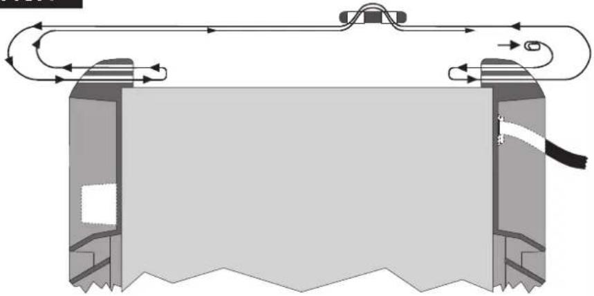
5.1 PREPARATION (FIG. P) 7
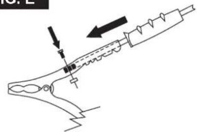
5.1.1 Assembling the return cable-clamp (FIG. E)....7
5.1.2 Assembling the welding cable-electrode holder clamp (FIG. E)....7
5.2 POSITION OF THE WELDING MACHINE....7
5.3 CONNECTION TO THE MAIN POWER SUPPLY....7
5.3.1 Plug and outlet 7
5.4 CONNECTION OF THE WELDING CABLES 7
5.4.1 TIG welding 7
5.4.2 MMA WELDING 7
- WELDING: DESCRIPTION OF THE PROCEDURE....7
page
6.1 TIG WELDING....7
6.1.1 HF and LIFT strike....8
6.1.2 TIG DC welding 8
6.1.3 TIG AC welding (if installed) 8
6.1.4 Procedure....8
6.2 MMA WELDING 8
6.2.1 Procedure....8
- MAINTENANCE 8
7.1 ROUTINE MAINTENANCE 8
7.1.1 Torch....8
7.2 EXTRAORDINARY MAINTENANCE 8
- TROUBLESHOOTING 8
INVERTER WELDING MACHINES FOR TIG AND MMA WELDING DESIGNED FOR INDUSTRIAL AND PROFESSIONAL USE.
Note: In the following text the term "welding machine" will be used.
- GENERAL SAFETY CONSIDERATIONS FOR ARC WELDING
The operator should be properly trained to use the welding machine and should be informed about the risks related to arc welding procedures, the associated protection measures and emergency procedures.
(Please refer to the applicable standard "EN 60974-9: Arc welding equipment. Part 9: Installation and Use).

- Avoid direct contact with the welding circuit: the no-load voltage supplied by the welding machine can be dangerous under certain circumstances.
- When the welding cables are being connected or checks and repairs carried out the welding machine should be switched off and disconnected from the power supply outlet.
- Switch off the welding machine and disconnect it from the power outlet before replacing consumable torch parts.
- Make the electrical connections and installation according to the safety rules and legislation in force.
- The welding machine should be connected only and exclusively to a power source with the neutral lead connected to earth.
- Make sure that the power supply plug is correctly connected to the protection outlet.
- Do not use the welding machine in damp or wet places and do not weld in the rain.
- Do not use cables with worn insulation or loose connections.

- Do not weld on containers or piping that contains or has contained flammable liquid or gaseous products.
- Do not operate on materials cleaned with chlorinated solvents or near such substances.
- Do not weld on containers under pressure.
- Remove all flammable materials (e.g. wood, paper, rags etc.) from the working area.
- Provide adequate ventilation or facilities for the removal of welding fumes near the arc; a systematic approach is needed in evaluating the exposure limits for the welding fumes, which will depend on their composition, concent and the length of exposure itself.
- Keep the gas bottle (if used) away from heat sources, including sunlight.


- Use electric insulation that is suitable for the torch, the workpiece and any metal parts that may be placed on the ground and nearby (accessible). This can normally be done by wearing gloves, footwear, head protection and clothing that are suitable for the purpose and by using insulating boards or mats.
- Always protect your eyes with the relative filters, which must comply with UNI EN 169 or UNI EN 379, mounted on masks or use helmets that comply with UNI EN 175.
Use the relative fire-resistant clothing (compliant with UNI EN 11611) welding gloves (compliant with UNI EN 12477) without exposing the skin to the ultraviolet and infrared rays produced by the arc; the protection extend to other people who are near the arc by way of screens (reflective sheets.
- Noise: If the daily personal noise exposure (LEPd) is equal to or higher than 85 dB(A) because of particularly intensive welding operations, suitable personal protective means must be used (Tab. 1).


- The flow of the welding current generates electromagnetic fields around the welding circuit.
Electromagnetic fields can interfere with certain medical equipment (e.g. Pacemakers, respiratory equipment, metallic prostheses etc.).
Adequate protective measures must be adopted for persons with these types of medical apparatus. For example, they must be forbidden access to the area in which welding machines are in operation.
safelywelding machine conforms to technical product standards for exclusive use in an industrial environment for professional purposes. It does not assure compliance with the basic limits relative to human exposure to electromagnetic fields in the domestic environment.
The operator must adopt the following procedures in order to reduce exposure to electromagnetic fields:
- Fasten the two welding cables as close together as possible.
- Keep head and trunk as far away as possible from the welding circuit.
- Never wind welding cables around the body.
- Avoid welding with the body within the welding circuit. Keep both cables on the same side of the body.
- Connect the welding current return cable to the piece being welded, as close as possible to the welding joint.
supply not weld while close to, sitting on or leaning against the welding machine (keep at least 50 cm away from it).
- Do not leave objects in ferromagnetic material in proximity of the welding circuit.
- Minimum distance d: 20 cm (Fig. O).

- Class A equipment:
This welding machine conforms to technical product standards for exclusive use in an industrial environment and for professional purposes. It does no assure compliance with electromagnetic compatibility in domestic dwellings and in premises directly connected to a low-voltage power supply system feeding buildings for domestic use.

EXTRA PRECAUTIONS
WELDING OPERATIONS:
- In environments with increased risk of electric shock.
- In confined spaces.
- In the presence of flammable or explosive materials.
MUST BE evaluated in advance by an "Expert supervisor" and must always be
I carried out in the presence of other people trained to intervene in emergencies.
All protective technical measures MUST be taken as provided in 7.10; cA.10 of the applicable standard EN 60974-9: Arc welding equipment. Part 9: Installation and Use".
- The operator MUST NOT BE ALLOWED to weld in raised positions unless safety platforms are used.
- VOLTAGE BETWEEN ELECTRODE HOLDERS OR TORCHES: working with more than one welding machine on a single piece or on pieces that are connected electrically may generate a dangerous accumulation of no-load voltage between two different electrode holders or torches, the value of which may reach double the allowed limit.
An expert coordinator must be designated to measuring the apparatus to determine if any risks subsist and suitable protection measures can be adopted, as foreseen by section 7.9 of the applicable standard "EN 60974-9: Arc welding equipment. Part 9: Installation and Use".

RESIDUAL RISKS
OVERTURNING: position the welding machine on a horizontal surface that is able to support the weight: otherwise (e.g. inclined or uneven floors etc.) there is danger of overturning.
- IMPROPER USE: it is hazardous to use the welding machine for any work other than that for which it was designed (e.g. de-icing mains water pipes).
- Do not use the handle to hang the welding machine.
- INTRODUCTION AND GENERAL DESCRIPTION 2.1 INTRODUCTION
(EMF)his welding machine is a power source for arc welding, made specifically for TIG (DC) (AC/DC) welding with HF or LIFT strike and MMA welding with coated electrodes
(rutile, acid, basic).
The particular features of this welding machine (INVERTER), such as high-speed and precise adjustment, result in excellent quality welds.
The inverter system of regulation at the power supply input (primary) also leads to a drastic decrease in the volume of both the transformer and the levelling reactance so that it is possible to build a considerably smaller, lighter welding machine, highlighting its advantages of easy handling and transport.
2.2 ACCESSORIES ON REQUEST (if not planned)
- Argon bottle adapter.
- Welding current return cable complete with earth clamp.
- Manual remote control with 1 potentiometer.
- Manual remote control with 2 potentiometers.
- Pedal remote control.
- MMA welding kit.
- TIG welding kit.
- Self-darkening mask: with fixed or adjustable filter.
- Gas connector and pipe for hook-up with Argon bottle.
- Pressure reducing valve with gauge.
- Torch for TIG welding.
- TIG torch with potentiometer.
- AMERICA trolley.
3. TECHNICAL DATA
3.1 DATA PLATE (FIG. A)
The most important data regarding use and performance of the welding machine are summarised on the rating plate and have the following meaning:
Protection rating of the covering
2- Symbol for power supply line:
1\~: single phase alternating voltage;
3\~: three phase alternating voltage.
3- Symbol S : indicates that welding operations may be carried out in environments with heightened risk of electric shock (e.g. very close to large metallic volumes).
4- Symbol for welding procedure provided.
5- Symbol for internal structure of the welding machine.
6- EUROPEAN standard of reference, for safety and construction of arc welding machines.
7- Manufacturer's serial number for welding machine identification (indispensable for technical assistance, requesting spare parts, discovering product origin).
8- Performance of the welding circuit:
- U : maximum no-load voltage (open welding circuit).
- I 2^7U2 : current and corresponding normalised voltage that the welding machine can supply during welding.
- X : Duly cycle: indicates the time for which the welding machine can supply the corresponding current (same column). It is expressed as %, based on a 10 minutes cycle (e.g. 60% = 6 minutes working, 4 minutes pause, and so on).
If the usage factors (on the plate, referring to a 40^ C environment) are exceeded, the thermal safeguard will trigger (the welding machine will remain in standby until its temperature returns within the allowed limits).
- A/V-A/V : shows the range of adjustment for the welding current (minimum maximum) at the corresponding arc voltage.
9- Technical specifications for power supply line:
- U _1 : Alternating voltage and power supply frequency of welding machine (allowed limit ±10%).
- I 1 max : Maximum current absorbed by the line.
- I 1 max: Effective current supplied.
10- : Size of delayed action fuses to be used to protect the power line.
11- Symbols referring to safety regulations, whose meaning is given in chapter 1 "General safety considerations for arc welding".
Note: The data plate shown above is an example to give the meaning of the symbols and numbers; the exact values of technical data for the welding machine in your possession must be checked directly on the data plate of the welding machine itself.
3.2 OTHER TECHNICAL DATA
- WELDING MACHINE: see table 1 (TAB.1).
- TORCH: see table 2 (TAB.2).
The welding machine weight is shown in table 1 (TAB. 1).
4. DESCRIPTION OF THE WELDING MACHINE
4.1 BLOCK DIAGRAM
The welding machine consists basically of power and control modules made on PCB's and optimised to achieve perfect reliability and reduced maintenance.
This welding machine is controlled by a microprocessor that allows a large number of parameter settings so as to achieve perfect welding in any condition and with any material. However, to make the best use of its properties it is necessary to be fully aware of its possibilities.
Description (FIG. B)
1- Three-phase power supply input, rectifier unit and levelling capacitors.
2- Transistor (IGBT) switching bridge and drivers; commutes the rectified power supply voltage to high frequency alternating voltage and adjusts the power according to the required welding current/voltage.
3- High frequency transformer; the voltage converted by block 2 powers the primary winding; its function is to adjust the voltage and current to the values needed for the arc welding procedure and at the same time to form galvanic separation of the welding circuit from the power supply line.
4- Secondary rectifier bridge with levelling inductance; commutes the alternating voltage / current supplied by the secondary winding into very low ripple direct current / voltage.
5- Transistor (IGBT) switching bridge and drivers; transforms the secondary output current from DC to AC for TIG AC welding (if present).
6- Control and adjustment electronics; controls the welding current value instantaneously and compares it with the operator's setting; modulates the control impulses from the IGBT drivers that make the adjustment.
7- Welding machine operation control logic; sets the welding cycles, controls the actuators, supervises the safety systems.
8- Settings panel and display of parameters and operating modes.
9- HF strike generator (if present).
10- Protective gas solenoid valve EV (if present).
11- Welding machine cooling fan.
12- Remote control.
4.2 CONTROL, ADJUSTMENT AND CONNECTING DEVICES
4.2.1 Rear panel (FIG. C)
1- Main switch O/OFF - I/ON.
2- Power cable (2 P + T (Single-phase)), (3 P + T (Three-phase)).
3- Coupler for connecting the gas hose (bottle - welding machine pressure reducer) (if present).
4- Fuse (if present).
5- Connector for water cooling unit (if present).
6- Connector for remote control:
Three different types of remote control can be connected to the welding machine using the relative 14-pole connector at the back. Each device is recognised automatically and can be used to adjust these parameters:
- Remote control with one potentiometer:
rotating the potentiometer knob varies the main current from minimum to maximum. The main current can only be adjusted with the remote control.
- Pedal remote command:
the value of the current is determined by the position of the pedal. Furthermore, in TIG 2T mode, pressing the pedal acts as a start command for the machine placed on the torch push-button (if installed).
- Remote control with two potentiometers:
the first potentiometer adjusts the main current. the second potentiometer adjusts another parameter that depends on the welding mode being used. Rotating this potentiometer displays the parameter being varied (which can no longer be controlled using the panel knob). The meaning of the second potentiometer is: ARC FORCE if in the MMA mode and END SLOPE if in the TIG mode.
- TIG torch with potentiometer.

It is obligatory to use a 5-pole torch adapter for any TIG TORCH with
an on-board adjustment potentiometer in order to protect the welding machine from internal breakage.
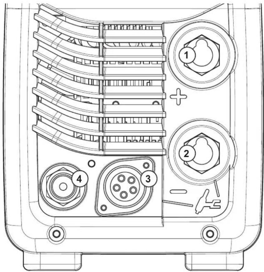
4.2.2 Front panel FIG. D
1- Positive (+) fast coupling for connecting the welding cable.
2- Negative (-) fast coupling for connecting the welding cable.
3- Connector for connecting the torch push-button
4- Coupler for connecting the TIG torch gas hose.
5- Control panel:
5a. Welding type setting push-button (PROCESS).
Allows selection of the desired process:

welding with coated electrode (MMA).

TIG welding with high frequency ark strike (TIG HF).

TIG welding with arc strike starting with contact (TIG HF).

in TIG mode, it indicates direct current welding (DC).

in TIG mode, it indicates alternating current welding (AC), if installed.
5b. Cycle setting push-button for TIG welding (MODE).
Enables selection of the operating mode.
Short press:

welding begins when the torch push-button is pressed and ends when the push-button is released.

welding begins when the torch push-button is pressed and released, and only when the torch push-button is pressed and released a second time.

welding begins when the torch push-button is pressed and released. On short press/release the current passes from the value set to the value

and vice versa. Welding ends when the push-button is pressed and then set for a set long time.

enables spot welding with duration time control of the welding on theay (flashing icon).

enables short spot welding (10-100msec) with duration time control of the ng on a display (flashing icon).
Prolonged pressing (PULSE):

enables pulsation of the current (level change) with setting as you wish of characteristic parameters I2, I1, and BAL

enables pulsation of the current with automatic settings to the predefined sets of the characteristic parameters 11. 12 and 13 based on the set (these values can however be modified).
5c. Multi-function knob.
Based on the pre-settings with the buttons, it enables selection and adjustment of the parameters by displaying the value set on the display.
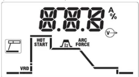
In particular, in M&A, the parameters that can be changed are:
text_image
87.876 A HOT START I2 ARC FORCE VRD
enabling/disabling the "Voltage Reduction Device" for a safe start at low ge.

initial overcurrent (0-100% adjustment) to optimise welding arc strike.

main welding current (output current in Amperes).

dynamic overcurrent (0-100% adjustment) to optimise fluidity of the welding avoid electrode sticking.
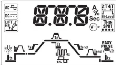
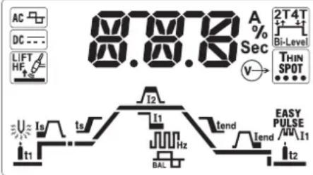
In particular, in TIG, the parameters that can be changed are:
text_image
87.87.12 A % Sec V→ 2T4T Bi-Level THIN SPOT I2 I1 I2 EASY PULSE I1 BAL t1 ts tend tend t2- pre-gas time of safety gas flow before starting welding (0-10 seconds adjustment).
- initial current maintained for a set time in 2T (50msec) and for the time the push-button is pressed, in 4T (0-100% adjustment).
- _s initial ramp time of the current from value I_s to I_2 (0.1-10 seconds adjustment). In OFF ramp not present.
N.B.: parameters I and T can also be modified with the pedal remot command. Adjustment, however, must be made before activating the command itself.
- _2 main welding current, in PULSED and Bi-Level mode is the current at higher level (output current in Amperes).
- basic current, in PULSED and Bi-Level mode is the value which can be alternated with the main one during welding (adjustment in Amperes).
- ( \text{J} ) ( \text{J} ) ( \text{J} ) ( \text{J} ) ( \text{J} ) ( \text{J} ) ( \text{J} ) ( \text{J} ) ( \text{J} ) ( \text{J} ) ( \text{J} ) ( \text{J} ) ( \text{J} ) ( \text{T} ) ( \text{A} ) ( \text{C} ) ( \text{A} ) ( \text{C} ) ( \text{A} ) ( \text{T} ) ( \text{A} ) ( \text{C} ) ( \text{A} ) ( \text{T} ) ( \text{A} ) ( \text{T} ) ( \text{A} ) ( \text{T} ) ( \text{A} ) ( \text{T} ) ( \text{A} ) ( \text{T} ) ( \text{T} ) ( \text{T} ) ( \text{T} ) ( \text{T} ) ( \text{T} ) ( \text{T} ) ( \text{T} ) ( \text{T} ) ( \text{T} ) ( \text{T} ) ( \text{T} ) ( \text{T} ) ( \text{T} ) ( \text{T} }^{1,2,3,4,5,6,7,8,9,10,11,12,13,14,15,16,17,18,19,20,21,22,23,24,25,26,27,28,29,30,31,32,33,34,35,36,37,38,39,40,41,42,43,44,45,46,47,48,49,50,51,52,53,54,55,56,57,58,59,60,61,62,63,64,65,66,67,68,69,70,71,72,73,74,75,76,77,78,79,80,81,82,83,84,85,86,87,88,89,90,91,92,93,94,95,96,97,98,99,100
- BAL balance percentage, in PULSED mode is the ratio between the time in which the current is at the highest level and the total pulsation period, for AC/DC models in TIG AC it represents the ratio between the time with positive current and the time with negative current.
- final ramp time of the current from value I_2 to I_end (0.1-10 seconds adjustment). In OFF ramp not present.
- final current, in 2T it is the current maintained after the final ramp if the ramp time is over zero, in 4T it is the current maintained after the final ramp for the entire time in which the torch push-button remains pressed.
- It2 post-gas time of safety gas flow starting from welding stoppage (0-10 seconds adjustment).
- pre-heating energy, if installed, only for AC/DC models in TIG AC adjusts pre-heating of the electrode to facilitate start-up (2.6-53 A*Sec adjustment). In OFF pre-heating not present.
Other explanatory icons on the display:
- ALARM warning/alarm, in general combined with the code indicated on the display, drawing attention to possible anomalies/automatic protection activated on the welding machine.
- thermal protection, combined with ALARM and the code on the display, warning the condition of internal heating limits has been reached.
- V→ active output, indicates voltage is present (power enabled) in the output sockets of the welding machine.
- remote command, indicates connection and control is active on the remote command.
- position pointer, in 4T with under a preset value, it indicates setting of a minimum initial current that makes the welding arc visible with push-button pressed. This allows precise selection of the starting point of the welding (if the initial current is set beyond a certain limit the function automatically disables).
- Default factory parameters, indicates setting of all the parameters at a preset value useful for wide-ranging operativity. The user can set the main current
as wished to alter the other automatic settings. It is possible to re-activate this condition at any time by switching off and back on the welding machine with the push-button on the multi-function knob (FIG. D - 5c) pressed.
Explanatory alarm messages on the alphanumerical display (FIG. D - 5d):
- AL.1 : the primary circuit protection thermal switch has been triggered (if installed).
- AL.2 : the secondary circuit protection thermal switch has been triggered.
- AL.3 : power line overvoltage protection has been triggered.
- AL.4 : power line undervoltage protection has been triggered.
AL.8 : auxiliary voltage out of range.
Resetting is automatic when the reason for alarm activation stops.
5. INSTALLATION

WARNING! CARRY OUT ALL INSTALLATION OPERATIONS AND ELECTRICAL CONNECTIONS WITH THE WELDING MACHINE COMPLETE SWITCHED OFF AND DISCONNECTED FROM THE POWER SUPPLY OUTLET. THE ELECTRICAL CONNECTIONS MUST BE MADE ONLY AND EXCLUSIVELY BY AUTHORISED OR QUALIFIED PERSONNEL.
5.1 PREPARATION (FIG. P)
Unpack the welding machine, assemble the separate parts contained in the package.
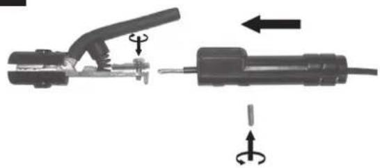
5.1.1 Assembling the return cable-clamp (FIG. E)
5.1.2 Assembling the welding cable-electrode holder clamp (FIG. E)
5.2 POSITION OF THE WELDING MACHINE
Choose the place to install the welding machine so that the cooling air inlets and outlets are not obstructed (forced circulation by fan, if present); at the same time make sure that conductive dusts, corrosive vapours, humidity etc. will not be sucked into the machine.
Leave at least 250mm free space around the welding machine.

WARNING! Position the welding machine on a flat surface with
sufficient carrying capacity for its weight, to prevent it from tipping or moving hazardously.
5.3 CONNECTION TO THE MAIN POWER SUPPLY
- Before making any electrical connection, make sure the rating data of the welding machine correspond to the mains voltage and frequency available at the place of installation.
- The welding machine should only be connected to a power supply system with the neutral conductor connected to earth.
- To ensure protection against indirect contact use residual current devices of the following types:
- Type A ( ) for single phase machines;
- Type B ( ) for 3-phase machines.
In order to satisfy the requirements of the EN 61000-3-11 (Flicker) standard we recommend connecting the welding machine to the interface points of the main power supply that have an impedance of less than: Zmax = 0.234 Ohm (1/N/PE 230V) 200A DC
The IEC/EN 61000-3-12 Standard does not apply to the welding machine. If the welding machine is connected to an electrical grid, the installer or user must make sure that the machine can indeed be connected (if necessary, consult the company that manages the electrical grid).
5.3.1 Plug and outlet
Connect a normalised plug (2P + P.E) (1\~); (3P + P.E) (3\~) - having sufficient capacity to the power cable and prepare a mains outlet fitted with fuses or an automatic circuit-breaker; the special earth terminal should be connected to the earth conductor (yellow-green) of the power supply line. Table (TAB.1) shows the recommended delayed fuse sizes in amps, chosen according to the max. nominal current supplied by the welding machine, and the nominal voltage of the main power supply.

WARNING! Failure to observe the above rules will make the (Class 1)
safety system installed by the manufacturer ineffective with consequent serious risks to persons (e.g. electric shock) and objects (e.g. fire).
5.4 CONNECTION OF THE WELDING CABLES

WARNING! BEFORE MAKING THE FOLLOWING CONNECTIONS MAKE SURE THE WELDING MACHINE IS SWITCHED OFF AND DISCONNECTED FROM THE POWER SUPPLY OUTLET.
Table (TAB. 1) gives the recommended values for the welding cables (in mm ^2 ) depending on the maximum current supplied by the welding machine.
5.4.1 TIG welding
Connecting the torch
- Insert the torch current cable into the appropriate quick terminal (-). Connect the three-pin connector (torch button) to the appropriate socket. Connect the torch gas pipe to the appropriate connector.
Connecting the welding current return cable
- This is connected to the piece to be welded or to the metal bench on which it rests, as close as possible to the joint being made.
This cable is connected to the terminal with the (+) symbol.
Connecting the gas bottle
- Screw the pressure reducing valve to the gas bottle valve, first inserting the special reduction accessory supplied when argon gas is used.
- Connect the gas inflow hose to the pressure reducing valve and tighten the hose clamp supplied.
- Loosen the ringnut for adjusting the pressure reducing valve before opening the valve on the bottle.
- Open the valve on the bottle and adjust the quantity of gas (l/min) according to the suggestions for use given in the table (TAB. 4); if it is necessary to adjust the gas flow during welding this should always be done by adjusting the ring nut on the pressure reduction valve. Make sure there are no leaks in the piping and connectors.
WARNING! Always close the gas bottle valve at the end of the job.
5.4.2 MMA WELDING
Almost all coated electrodes are connected to the positive pole (+) of the power source; as an exception to the negative pole (-) for acid coated electrodes.
Connecting the electrode-holder clamp welding cable
On the end take a special terminal that is used to close the uncovered part of the electrode.
This cable is connected to the terminal with the symbol (+)
Connecting the welding current return cable
This is connected to the piece being welded or to the metal bench supporting it, as close as possible to the join being made.
This cable is connected to the terminal with the symbol (-)
Warnings:
- Turn the welding cable connectors right down into the quick connections (if present), to ensure a perfect electrical contact; otherwise the connectors themselves will overheat, resulting in their rapid deterioration and loss of efficiency.
- The welding cables should be as short as possible.
- Do not use metal structures which are not part of the workpiece to substitute the return cable of the welding current: this could jeopardise safety and result in poor welding.
6. WELDING: DESCRIPTION OF THE PROCEDURE
6.1 TIG WELDING
TIG welding is a welding procedure that exploits the heat produced by the electric arc that is struck, and maintained, between a non-consumable electrode (tungsten) and the piece to be welded. The tungsten electrode is supported by a torch suitable for transmitting the welding current to it and protecting the electrode itself and the weld pool from atmospheric oxidation, by the flow of an inert gas (usually argon: Ar 99.5) which flows out of the ceramic nozzle (FIG. G).
To achieve a good weld it is absolutely necessary to use the exact electrode diameter with the exact current, see the table (TAB. 3).
The electrode usually protrudes from the ceramic nozzle by 2-3mm, but this may reach 8mm for corner welding.
Welding is achieved by fusion of the edges of the joint. For properly prepared thin pieces (up to about 1mm) weld material is not needed (FIG. H).
For thicker pieces it is necessary to use filler rods of the same composition as the base material and with an appropriate diameter, preparing the edges correctly (FIG. I). To achieve a good weld the pieces should be carefully cleaned and free of oxidation, oil, grease, solvents etc.
6.1.1 HF and LIFT strike
HF strike:
The electric arc is struck without contact between the tungsten electrode and the piece being welded, by means of a spark generated by a high frequency device. This strike mode does not entail either tungsten inclusions in the weld pool or electrode wear and gives an easy start in all welding positions.
Procedure:
Press the torch button, bringing the tip of the electrode close to the piece (2 -3mm), wait for the arc strike transferred by the HF pulses and, when the arch has struck, form the weld pool on the piece and proceed along the joint.
If there are difficulties in striking the arc even though the presence of gas is confirmed and the HF discharges are visible, do not insist for long in subjecting the electrode to HF action, but check the integrity of the surface and the shape of the tip, dressing it on the grinding wheel if necessary. At the end of the cycle the current will fall at the
slope down setting.
LIFT strike:
The electric arc is struck by moving the tungsten electrode away from the piece to be welded. This strike mode causes less electrical-radiation disturbance and reduces tungsten inclusions and electrode wear to a minimum.
Procedure:
Place the tip of the electrode on the piece, using gentle pressure. Press the torch button right down and lift the electrode 2-3mm with a few moments' delay, thus striking the arc. Initially the welding machine supplies a current I_Lift , after a few moments the welding current setting will be supplied. At the end of the cycle the current will fall to zero at the slope down setting.
6.1.2 TIG DC welding
TIG DC welding is suitable for all low- and high-carbon steels and the heavy metals, copper, nickel, titanium and their alloys.
For TIG DC welding with the electrode to the (-) terminal the electrode with 2% thorium (red band) is usually used or else the electrode with 2% cerium (grey band).
It is necessary to sharpen the tungsten electrode axially on the grinding wheel, as shown in FIG. L, making sure that the tip is perfectly concentric to prevent arc deviation. It is important to carry out the grinding along the length of the electrode. This operation should be repeated periodically, depending on the amount of use and wear of the electrode, or when the electrode has been accidentally contaminated, oxidised or used incorrectly.
6.1.3 TIG AC welding (if installed)
This type of welding can be used to weld metals such as aluminium and magnesium, which form a protective, insulating oxide on their surface. By reversing the welding current polarity it is possible to "break" the surface layer of oxide by means of mechanism called "ionic sandblasting". The voltage on the tungsten electrode alternates between positive (EP) and negative (EN). During the EP period the oxide is removed from the surface ("cleaning" or "pickling") allowing formation of the pool. During the EN period there is maximum heat transfer to the piece, allowing welding. The possibility of varying the balance parameter in AC means that it is possible to reduce the EP current period to a minimum, allowing quicker welding.
Higher balance values give quicker welding, greater penetration, a more concentrated arc, a narrower weld pool and limited heating of the electrode. Lower values give a cleaner piece. If the balance value is too low this will widen the arc and the de-oxidised part, overheat the electrode with consequent formation of a sphere on the tip making it more difficult to strike the arc and control its direction. If the balance value is too high this will create a "dirty" weld pool with dark inclusions.
The table (TAB. 4) summarises the effects of parameter changes in AC welding. The instructions for this welding procedure are also valid.
The table (TAB. 3) shows suggested values for welding on aluminium; the most suitable electrode is a pure tungsten electrode (green band).
6.1.4 Procedure
- Use the knob to adjust the welding current to the desired value; if necessary adjust during welding to the actual required heat transfer.
- Press the torch button and make sure the gas flow from the torch is correct; if necessary, adjust pre-gas and postgas times; these times should be adjusted according to operating conditions, the postgas delay in particular should be long enough to allow the electrode and weld pool to cool at the end of welding without coming into contact with the atmosphere (oxidation and contamination).
TIG mode with 2T sequence:
- Press the torch button (P.T.) right down to strike the arc with a current of I_s . The current will increase according to the START SLOPE UP setting to the weldir current value.
- To interrupt welding, release the torch button so that either the current gradually decreases (if the FINAL SLOPE DOWN parameter has been enabled) or the arc is extinguished immediately, followed by postgas.
TIG mode with 4T sequence:
- The first time the button is pressed it will strike the arc with a current equal to I. When the button is released the current will increase according to the START SLOPE UP setting to the welding current value; this value is maintained even with the button is released. When the button is pressed again the current will decrease according to the FINAL SLOPE DOWN setting, until it reaches I_end . The I_end current will be maintained until the button is released to terminate the welding cycle and start the postgas phase. If, on the other hand, the button is released while the FINAL SLOPE DOWN function is proceeding, the welding cycle will terminate immediately and the postgas phase will start.
TIG mode with 4T and BI-LEVEL sequence:
- The first time the button is pressed it will strike the arc with a current equal to I. When the button is released the current will increase according to the START SLOPE UP setting to the welding current value; this value is maintained even when the button is released. Now, every time the button is pressed (the time between pressure and release should be short) the current will change between the setting for the BI-LEVEL I, parameter and the main current value I.
- When the button is kept pressed down for a longer space of time the current will decrease according to the FINAL SLOPE DOWN setting, until it reaches I_end . The I_end current will be maintained until the button is released to terminate the welding cycle and start the postgas phase. If, on the other hand, the button is released while the FINAL SLOPE DOWN function is proceeding, the welding cycle will terminate immediately and the postgas phase will start (FIG. M).
TIG SPOT and TIG THIN SPOT mode:
- Welding is carried out by keeping the torch push-button pressed until the pre-set time has been reached (spot time).
6.2 MMA WELDING
- It is most important that the user refers to the maker's instructions indicated on the stick electrode packaging. This will indicate the correct polarity of the stick electrode and the most suitable current.
- The welding current must be regulated according to the diameter of the electrode in use and the type of the joint to be carried out: see below the currents corresponding to various electrode diameters:
| ∅ Electrode (mm) | Welding current (A) | |
| Min. Max. | ||
| 1.6 25 50 | ||
| 2 40 80 | ||
| 2.5 60 110 | ||
| 3.2 80 160 | ||
| 4 120 200 | ||
| 5 150 280 | ||
| 6 200 350 | ||
- The user must consider that, according to the electrode diameter, higher current values must be used for flat welding, whereas for vertical or overhead welds lower current values are necessary.
- As well as being determined by the chosen current intensity, the mechanical characteristics of the welded join are also determined by the other welding parameters i.e. arc length, working rate and position, electrode diameter and quality (to store the electrodes correctly, keep them in a dry place protected by their packaging or containers).
- The properties of the weld also depend on the ARC-FORCE value (dynamic behaviour) of the welding machine. The setting for this parameter can be made either on the panel or using the remote control with 2 potentiometers.
- It should be noted that high ARC-FORCE values achieve better penetration and allow welding in any position typically with basic electrodes, low ARC-FORCE values give a softer, spray-free arc typically with rutile electrodes. The welding machine is also equipped with HOT START and ANTI STICK devices to guarantee easy starts and to prevent the electrode from sticking to the piece.
6.2.1 Procedure
- Holding the mask IN FRONT OF THE FACE, strike the electrode tip on the workpiece as if you were striking a match. This is the correct strike-up method.
WARNING: do not hit the electrode on the workpiece, this could damage the electrode and make strike-up difficult. - As soon as arc is ignited, try to maintain a distance from the workpiece equal to the diameter of the electrode in use. Keep this distance as much constant as possible for the duration of the weld. Remember that the angle of the electrode as it advances should be of 20-30 grades.
- At the end of the weld bead, bring the end of the electrode backward, in order to fill the weld crater, quickly lift the electrode from the weld pool to extinguish the arc (CHARACTERISTICS OF THE WELD BEAD - FIG. N).
7. MAINTENANCE

- Do not put the torch or its cable on hot pieces; this would cause the insulating materials to melt, making the torch unusable after a very short time.
- Make regular checks on the gas pipe and connector seals.
- Accurately match collet and collet body with the selected electrode diameter in order to avoid overheating, bad gas diffusion and poor performance.
- At least once a day check the terminal parts of the torch for wear and make sure they are assembled correctly: nozzle, electrode, electrode-holder clamp, gas diffuser.
7.2 EXTRAORDINARY MAINTENANCE
EXTRAORDINARY MAINTENANCE MUST ONLY BE CARRIED OUT BY TECHNICIANS WHO ARE EXPERT OR QUALIFIED IN THE ELECTRIC-MECHANICAL FIELD, AND IN FULL RESPECT OF THE IEC/EN 60974-4 TECHNICAL DIRECTIVE.

WARNING! BEFORE REMOVING THE WELDING MACHINE PANELS AND WORKING INSIDE THE MACHINE MAKE SURE THE WELDING MACHINE IS SWITCHED OFF AND DISCONNECTED FROM THE MAIN POWER SUPPLY OUTLET.
If checks are made inside the welding machine while it is live, this may cause serious electric shock due to direct contact with live parts and/or injury due to direct contact with moving parts.
- Periodically, and in any case with a frequency in keeping with the utilisation and with the environment's dust conditions, inspect the inside of the welding machine and remove the dust deposited on the electronic boards with a very soft brush or with appropriate solvents.
- At the same time make sure the electrical connections are tight and check the wiring for damage to the insulation.
- At the end of these operations re-assemble the panels of the welding machine and screw the fastening screws right down.
- Never, ever carry out welding operations while the welding machine is open.
- After having carried out maintenance or repairs, restore the connections and wiring as they were before, making sure they do not come into contact with moving parts or parts that can reach high temperatures. Tie all the wires as they were before, being careful to keep the high voltage connections of the primary transformer separate from the low voltage ones of the secondary transformer. Use all the original washers and screws when closing the casing.
8. TROUBLESHOOTING
IN CASE OF UNSATISFACTORY FUNCTIONING, BEFORE SERVICING MACHINE OR REQUESTING ASSISTANCE, CARRY OUT THE FOLLOWING CHECK:
- Check that the welding current is correct for the diameter and electrode type in use.
- Check that when general switch is ON the relative lamp is ON. If this is not the case then the problem is located on the mains (cables, plugs, outlets, fuses, etc.).
- Check that the yellow led (ie. thermal protection interruption- either over or undervoltage or short circuit) is not lit.
- Check that the nominal intermittance ratio is correct. In case there is a thermal protection interruption, wait for the machine to cool down, check that the fan is working properly.
- Check the mains voltage: if the value is too high or too low the welding machine will be stopped.
- Check that there is no short-circuit at the output of the machine: if this is the case eliminate the incovenience.
- Check that all connections of the welding circuit are correct, particularly that the work clamp is well attached to the workpiece, with no interfering material or surface-coverings (ie. Paint).
- Protective gas must be of appropriate type (Argon 99.5%) and quantity.
ITALIANO
INDICE
pag.
-
SICUREZZA GENERALE PER LA SALDATURA AD ARCO....10
-
INTRODUZIONE E DESCRIZIONE GENERALE....10
2.1 INTRODUZIONE 10
text_image
87.87A HOT START 12 ARC FORCE VRDVRD
2.1 INTRODUCTION....16
5.1 INSTALLATION (FIG. P)....17
5.1 INSTALLATION (FIG. P)
1- Interruptor geral ON/OFF - I/ON.
- BESCHRIJVING VAN DE LASMACHINE ....46
4.1 BLOKJESSCHEMA....46
4.2 BESTURINGS-, REGEL- EN AANSLUITORGANEN....46
4.2.1 Achterpaneel (FIG. C) 46
4.2.2 Voorpaneel FIG. D....46
- INSTALLATIE ....47
- PROBLEEMOPLOSSINGEN ....49
LASMACHINES MET INVERTER VOOR HET TIG- EN MMA LASSEN VOORZIEN
VOOR HET INDUSTRIEEL EN PROFESSIONEEL GEBRUIK.
3.1 KENTEKENPLAAT (FIG. A)
4. BESCHRIJVING VAN DE LASMACHINE
4.1 BLOKJESSCHEMA
2.1 INTRODUCERE ....56
4.2.1 Bakre panel (FIG. C)....61
4.2.2 Främre panel FIG. D 61
- INSTALLATION 62
5.1 IORDNINGSTÄLLNING (FIG. P)....62
- INLEDNING OCH ALLMÄN BESKRIVNING
2.1 INLEDNING
5.1 OPSTILLING (FIG. P) 67
5.1.1 Samling af returkabel-tang (FIG. E) 67
- Argon-beholder adapter.
12- Fjernregulering.
4.2 KONTROL-, REGULERINGS- OG TILSLUTNINGSANORDNINGER
4.2.1 Bagpanel (FIG. C)
1- Hovedafbryder O/OFF - I/ON
2- Forsyningskabel (2P + E (enfaset)), (3P + E (trefaset)).
5.1 OPSTILLING (FIG. P)
4.2.1 Bakre panel (FIG. C)....71
4.2.2 Panel foran FIG. D 71
- INSTALLASJON ....72
5.1 MONTERING (FIG. P)....72
5.3 KOPLING TIL NETTET....72
7.1 ALMINDELIG VEDLIKEHOLD....73
7.1.1 Sveisebrenner 73
7.2 EKSTRAORDINÄERT VEDLIKEHOLD 73
- FEILS∅KING 73
SVEISEBRENNER MED INVERTER FOR TIG- OG MMA-SVEISING FOR BRUK I
EKSTRA FORHOLDSREGLER
- SVEISEOPERASJONER:
- I miljöer med stor risiko for elektrisk støt.
- I avgrenset mijøer.
1- Hovedbryter O/OFF - I/ON.
text_image
87.878 A% HOT START ARC FORCE VRD5.3 KOPLING TIL NETTET
7.1 ALMINDELIG VEDLIKEHOLD
ALMINDELIGE VEDLIKEHOLDSOPERASJONER KAN FULLF∅RES AV OPERAT∅REN.
7.1.1 Sveisebrenner
6.1.4 Menettely....78
6.2 MMA-HITSAUS 78
6.2.1 Hitsausmenettely....78
- HUOLTO ....78
7.1 TAVALLINEN HUOLTO....78
7.1.1 Poltin 78
7.2 ERIKOISHUOLTO 78
- VIKAHAKU....78
TEOLLISUUS- JA AMMATTIKÄYTTÖÖN TARKOITETUT TIG- JA MMA-INVERTTEREIHITSAUSKONEET.
text_image
87.876 A% HOT START 12 ARC FORCE VRD
5.1 MONTÁŽ (OBR. P)....82
- UVOD IN SPLOŠNI OPIS
2.1 UVOD
text_image
87.878 A% HOT START ARC FORCE VRDNačin TIG SPOT in TIG THIN SPOT:
5.1 PRIPREMA (FIG. P) 97
5.1.1 Sastavljanje povratnog kabla-hvataljke (FIG. E)....97
5.1.2 Sastavljanje kabla za varenje-hvatajke za držanje elektrode (FIG. F)..97
5.2 POLOŽAJ STROJA ZA VARENJE 97
5.3 PRIKLJUČIVANJE NA STRUJNU MREŽU 97
5.3.1 UTIKAČ I UTIČNICA 97
5.4 PRIKLJUČIVANJE KRUGA VARENJA 97
5.4.1 Varenje TIG 97
5.4.2 Varenje MMA....97
- VARENJE: OPIS PROCEDURE 97
6.1 VARENJE TIG 97
6.1.1 Paljeje HF i LIFT....98
6.1.2 Varenje TIG DC 98
6.1.3 Zavarivanje TIG AC (ako je predviđeno) 98
6.1.4 Procedura....98
6.2 VARENJE MMA....98
6.2.1 Procedura 98
- SERVISIRANJE 98
7.1 REDOVNO SERVISIRANJE 98
7.1.1 SERVISIRANJE Plamenik....98
7.2 IZVANREDNO SERVISIRANJE 98
- POTRAGA ZA KVAROVIMA ....98
STROJEVI ZA VARENJE SA INVERTEROM ZA VARENJE TIG I MMA ZA INDUSTRIJU I PROFESIONALNU UPOTREBU.
text_image
8.78.78 A% HOT START 12 ARC FORCE VRD- VRD omogućavanje/onemogućavanje uređaja "Voltage Reduction Device" za sigurno pokretanje pri niskom naponu.
HOT START - START početna prevelika struja (podešavanje 0-100%) za optimiranje paljenja električnog luka zavarivanja.
- glavna struja zavarivanja (izlazna struja u Amperima).
- ARC FORCE dinamička prevelika struja (podešavanje 0-100%) da se optimira fluidnost zavarivanja i izbjegne ljepljenje elektrode.
Posebice u režimu TIG parametri koji se mogu promljeniti jesu sljedeći:
text_image
87.8.18 A % Sec V→ 2T4T Bi-Level THIN SPOT Is ts I2 L t1 Hz BAL tend Iend EASY PULSE I1 t2- t1 vrijeme pred-plina odljeva zaštitnog plina prije početka zavarivanja (podešavanje 0-10 sekundi).
- Početna struja koja se održala za fiksno vrijeme u 2T (50msec) i za vrijeme za koje je tipka ostala pritisnuta, u 4T (podešavanje 0-100%).
- t_s početno vrijeme rampe struje od vrijednosti I s do I 2 (podešavanje 0.1-10 sekundi). U režimu OFF rampa ne postoji.
NAPOMENA: parametri I, I T mogu se promijeniti i preko daljinske komande na papučicu, ali podešavanje treba izvršiti prije aktiviranja same komande.
- glavna struja zavarivanja, u režimu PULSIRANJE i Bi-Level struja je na najvišoj razini (izlazna struja u Amperima).
- osnovna struja, u režimu PULSIRANJE i Bi-Level u pitanju je vrijednost koja se može smjenjivati s glavnom vrijednosti za vrijeme zavarivanja (podešavanje u Amperima).
- frekvencija pulsiranja i za modele AC/DC u režimu TIG AC predstavlja frekvenciju struje zavarivanja (podešavanje u Hertz).
- BAL postotak balansiranja, u režimu PULSIRANJE u pitanju je odnos između vremena kada je struja na najvišoj razini i ukupnog perioda pulsiranja, za modele AC/DC u režimu TIG AC predstavlja odnos između vremena s pozitivnom strujom i vremena s negativnom strujom.
- krajnje vrijeme rampe struje od vrijednosti I 2 do I and (podešavanje 0.1-10 sekundi). U režimu OFF rampa ne postoji.
- krajnja struja, u 2T predstavlja struju koja se održala nakon krajnje rampe ako je vrijeme rampe veće od nule, u 4T predstavlja struja koja se održala nakon krajnje rampe za sve vrijeme za koje je tipka plamenika ostala pritisnuta.
- It2 vrijeme pred-plina odljeva zaštitnog plina od zaustavljanja zavarivanja (podešavanje 0-10 sekundi).
- energija predgrijavanja, ako je predviđeno, samo za modele AC/DC u TIG AC podešava predgrijavanje elektrode da se olakša početak (podešavanje 2.6-53 A*Sek.). U režimu OFF predgrijavanje ne postoji.
Ostale indikativne oznake koje se nalaze na zaslonu:
- ALARM signal/alarm, obično je kombiniran sa šifrom prikazanom na zaslonu, priziva pažnju na mogući problem/uključenu automatsku zaštitu na aparatu za zavarivanje.
- termička zaštita, kombinirana s ALsfrom na zaslonu, upozorenje da je dostignuta granica internog zagrijavanja.
5.1 PRIPREMA (FIG. P)
- TECHNINIAI DUOMENYS ....101
3.1 DUOMENU LENTELÉ....101
3.2 KITI TECHNINIAI DUOMENYS....101
- SUVIRINIMO APARATO APRAŠYMAS 101
4.1 BLOKU SCHEMA 101
4.2 VALDYMO JTAISAI, REGULIAVIMAS IR PRIJUNGIMAS....101
4.2.1 Galinis skydas (C PAV.)....101
4.2.2 Priekinis skydas D PAV....101
- INSTALIAVIMAS ....102
5.1 PARUOŠIMAS (PAV. P)....102
5.1.1 Atgalinio kabelio- gnybto surinkimas (PAV. E)....102
5.1.2 Suvirinimo kabelio- elektrody laikiklio gnybto surinkimas (PAV. F).....102
5.2 SUVIRINIMO APARATO PASTATYMAS 102
5.3 PRIJUNGIMAS PRIE TINKLO....102
5.1 PARUOŠIMAS (PAV. P)
5.1 MONTAAŽ (PILT P)....107
5.1.1 Tagasisidekaabli/klemmi montaaž (PILT E)....107
text_image
87.878 A% HOT START ARC FORCE VRD

5.1 MONTAAŽ (PILT P)
KEEVITAJA VÕIB TEOSTADA NORMAALSEID HOOLDUSTÕID.
7.1.1 PÖLETI HOOLDUS
6.1 TIG METINĂŠANA 113
text_image
87.876 A HOT START 12 ARC FORCE VRDTryb TIG SPOT i TIG THIN SPOT:
6.2 SPAWANIE METODA MMA
text_image
87.87A HOT START 12 ARC FORCE VRD- airport airport airport airport airport airport airport airport airport airport airport airport airport airport airport airport airport airport airport airport airport airport airport airport airport airport airport airport airport airport airport airport airport airport airport airport airport airport airport airport airport airport airport airport airport airport airport airport airport airport airport airport airport airport airport airport airport airport airport airport airport airport airport airport airport airport airport airport airport airport airport airport airport airport airport airport airport airport airport airport airport airport airport airport airport airport airport airport airport airport airport airport airport airport airport airport airport airport airport airport Airport airport Airport airport Airport airport Airport Airport Airport Airport Airport Airport Airport Airport Airport Airport Airport Airport Airport Airport Airport Airport Airport Airport Airport Airport Airport Airport Airport Airport Airport Airport Airport Airport Airport Airport Airport Airport Airport Airport Airport Airport Airport Airport Airport Airport Airport Airport Airport Airport Airport Airport Airport Airport Airport Airport Airport Airport Airport Airport Airport Airport Airport Airport Airport Airport Airport Airport Airport Airport Airport Airport Airport Airport Airport Airport Airport Airport Airport Airport Airport Airport Airport Airport Airport Airport Airport Airport Airport Airport Airport Airport Airport Airport Airport Airport Airport Airport Airport Airport Airport Airport Airport Airport Airport Airport airports
ماس کهربای.
- Business Department Office, Department of the United States, Department of the United Kingdom, Department of the United Kingdom, Department of the United States, Department of the United Kingdom, Department of the United States, Department of the United Kingdom, Department of the United States, Department of the United Kingdom, Department of the United States, Department of the United Kingdom, Department of the United States, Department of the United Kingdom, Department of the United States, Department of the United Kingdom, Department of the United States, Department of the United Kingdom, Department of the United States, Department of the United Kingdom, Department of the United States, Department of a Department of the United States, Department of a Department of the United Kingdom, Department of a Department of the United Kingdom, Department of a Department of the United Kingdom, Department of a Department of the United Kingdom, Department of a Department of the United Kingdom, Department of a Department of the United Kingdom, Department of a Department of the United Kingdom, Department of a Department of the United Kingdom, Department of a Department of the United Kingdom, Department of a Department of the United Kingdom, Department of a Department of the United Kingdom, Department of a Department of the United Kingdom
text_image
Technical diagram of a portable air conditioner unit with labeled components and internal structureFIG. D
text_image
Technical diagram of a device rear panel with labeled components including connectors, switches, and ports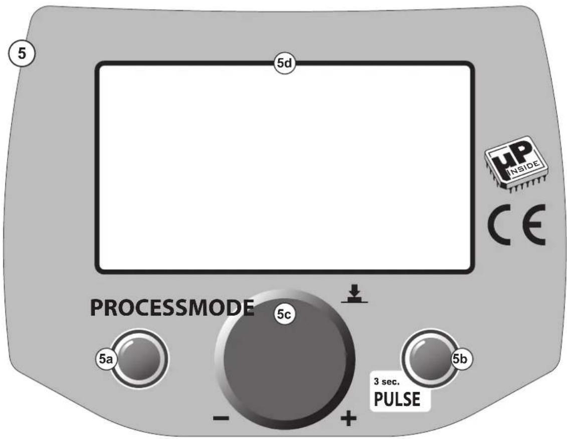
text_image
5 5d UP INSIDE CE PROCESSMODE 5c 5a 5b 3 sec. PULSEFIG. E
natural_image
Technical line drawing of a mechanical tool or device with directional arrows indicating movement (no text or symbols)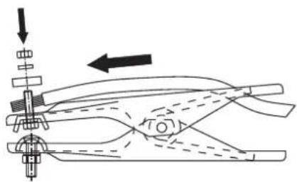
natural_image
Pure mechanical diagram showing a clamping device with no text, numbers, or symbols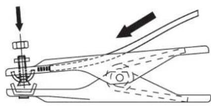
natural_image
Technical line drawing of a mechanical clamp or tool with directional arrows indicating movement (no text or symbols)FIG. F
natural_image
Mechanical welding process diagram showing tool insertion and rotation (no text or symbols)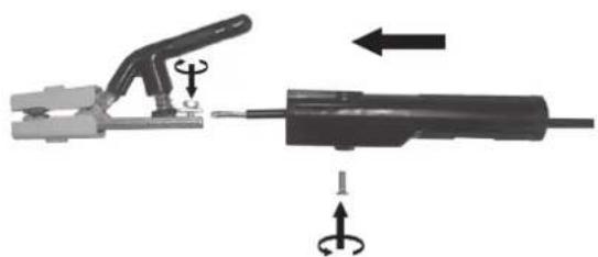
natural_image
Diagram of a welding torch and tool assembly with directional arrows indicating motion (no text or symbols)SUGGESTED VALUES FOR WELDING - DATI ORIENTATIVI PER SALDATURA -
text_image
Technical diagram of a welding torch and clamp assembly with numbered componentsTORCH
TORCIA
TORCHE
BRENNER
SOPLETE
TOCHA
TOORTS
BRÆNDER
POLTIN
SVEISEBRENNER
SKÄRBRÄNNARE
ΛΑΜΠΑ
ГОРЕЛКА
الشعلة
1- FILLER ROD IF NEEDED - EVENTUALE BACCHETTA D'APPORTO - BAGUETTE D'APPORT ÉVENTUELLE - BEDARFSWEISE EINGESETZTER SCHWEISSSTAB MIT ZUSATZWERKSTOFF - EVENTUAL VARILLA DE APORTE - EVENTUAL VARETA DE ENCHIMENTO - EVENTUEEL STAAFJE VAN TOEVOER - EVENTUEL TILSATSSTAV - MAHDOLLINEN LISÄAINESAUVA - STÖTTEPINNE - EVENTUELL STAV FÖR PÄSVETSNING - ENDEXOMENH PABAOΣ EIZAΓΩΓΗΣ - ВОЗМОЖНАЯ ПАЛОЧКА ДЛЯ ПРИПОЯ - قطعة حشو محتملة
2- NOZZLE - UGELLO - TUYÈRE - DÜSE - BOQUILLA - BICO - SPROEIER - DYSE - SUUTIN - SMÖRENIPPEL - MUNSTYCKE - MПЕК - СОПЛО. دوايّة
3- PUSHBUTTON - PULSANTE - BOUTON
- DRUCKKNOPF - PULSADOR - BOTÃO -
DRUKKNOP - TRYKKNAP - PAINIKE - TAST -
KNAPP - ΠΛΗΚΤΡΟ - ΚΗΟΠΚΑ -
4- GAS - GAS - GAZ - GAS - GAS - GÁS - GAS - GAS - GAS - GASS - GASEN - ADPANEΣ AEPIO - ΓA3 - غاز
5- CURRENT - CORRENTE - COURANT - STROM - CORRIENTE - CORRENTE - STROOM - STRÖM - STRÖM - STRÖM - PEYMA - TOK - نبار
6- TORCH BUTTON CABLES - CAVI PULSANTE
TORCIA - CÂBLES POUSSOIR TORCHE - KABEL
BRENNERKNOPF - CABLES DEL PULSADOR
SOPLETE - CABOS BOTÃO TOCHA - KABELS
DRUKKNOP TOORTS - BRÆNDERKNAPKABEL
- PURISTIMEN PAINONAPIN KAPELIT -
KABLER TIL SVEISEBRENNERENS TAST -
natural_image
Pure mechanical cross-section diagram without any text, numbers, or symbols- Preparation of the folded edges for welding without weld material.
- Preparazione dei lembi rivoltati da saldare senza materiale d'apporto.
- Préparation des bords relevés pour soudage sans matériau d'apport.
- Herrichtung der gerichteten Kanten, die ohne Zusatzwerkstoff geschweißt werden.
- Preparación de los extremos rebordeados a soldar sin material de aporte.
- Preparação das abas viradas a soldar sem material de entrada.
- Voorbereiding van de te lassen omgekeerde randen zonder lasmateriaal.
- Forberedelse af de foldede klapper, der skal svejses uden tilført materiale.
- Hitsattavien käännettyjen reunojen valmistelu ilman lisämateriaalia.
- Forberedelse av de vendte flikene som skal sveises uten ekstra materialer.
- Förberedelse av de vikta kanterna som ska svetsas utan påsvetsat material.
- Προετοιμασία των γυρισμένων χειλών που θα συγκολληθούν χωρίς υλικό τροφοδοσίας.
- Подготовка подвернутых свариваемых краев без материала припоя.
line
| Time | Current | |------|---------| | Start | 0 | | EP+ | 1 | | End | 0 |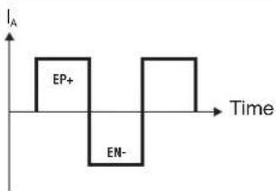
text_image
IA EP+ EN- Time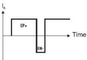
text_image
I_A EP+ EN- TimeTIG AC
- MAX PENETRATION
- MIN CLEANESS
- MIN CONSOPTION OF TUNGSTEN ELECTROCE
- MAX EFFICIENCY (FAST WELDING)
MAX PENETRAZIONE
- MIN PULIZIA MIN CONSUN
- MIN CONSUMO ELETTRUDO TUNGSTENO
- MAX RENDIMENTO (SALDATURA
VELOCE)
- MAX PENETRATION
- MIN NETTOYAGE MIN CONSOOMA
MIN CONSUMMATION D'ELECTRODE DE TUNGSTENE
- STANDARD VALUE
(RECOMMENDED)
- BEST BALANCE BETWEEN EP+ AND EN- (50-50)
- VALORE STANDARD
(RACCOMANDATO)
- OTTIMO BILANCIAMENTO TRAEP+ E EN- (50-50)
- VALEUR STANDARD
(RECOMMANDE
- EQUILIBRE OPTIMAL ENTRE LE EP+ ET EN+ (50-50)
- MAX CLEANESS
- MIN PENETRATION - MAY CONSURTION
MAX CONSO ELECTRODE
- MIN EFFICIENCY (SLOW WELDING)
- MAX PULIZIA
- MIN PENETRAZIONE
- MAX CONSUMO ELETTRODO TUNGSTENO
- MIN RENDIMENTO (SALDATURA LENTA)
- MAX NETTOYAGE
- MIN PENETRATION MAX CONSOUMATION/VELECTROPE
- MAX CONSUMM DE TUNGSTENE
- MAX RENDEMENT (SOUDAGE RAPID)
- MAX PENETRACIÓN
MIN LIMPIEZA - MIN CONSUMO ELECTRODO DE TUNGSTENO
TONGSTENO MÁXIMO REND
RÁPIDA) - HÖCHSTES DURCHDRINGEN
- GERINGSTE REINIGUNG
- GERINGSTER VERBRAUCH VON WOLERAM ELEKTRODE
-
HÖCHSTE LEISTUNG (SCHNELLES
SCHWEISSEN) -
VALOR ESTÁNDAR
(RECOMENDADU) - SALDO OPTIMO ENTRE EL PE + Y ES-(50-50)
- STANDARD WERT (EMPFOHLEN)
- SEHR GUTE AUSGLEICH
ZWISCHEN EP + UND EN- (50-50) - СТАНДАРТНОЕ ПРЕИМУЩЕСТВО
(РЕКОМЕНДУЕТСЯ) -
ЛУЧШИЙ БАЛАНС МЕЖДУ + И -
(50-50) -
MIN RENDEMENT (SOUDAGE LENT)
MAY LIMPIEZA - MIN DE PENETRACIÓN
- MAX CONSUMO ELECTRODO DE
TUNGSTENO MIN DENDIM - MIN RENDIMIENTO (SOLDADORA)
- HÖCHSTE REINIGUNG
GERINGSTES DURCHDRINGEN - HOCHSTER VERBRAUCH VON WOLFERM ELEKTRODE
-
GERINGSTE LEISTUNG
SCHWEISSEN) -
МАКСИМАЛЬНОЕ ПРОНИКНОВЕНИЕ
- МИНИМАЛЬНАЯ ЧИСТОТА МИНИМАЛЬНЫЙ ДАСХОЛ
- КИМИНАЛЬНЫЙ РАСХОД ВОЛЬФРАМОВЫМ ЭЛЕКТРОДОМ
- МАКСИМАЛЬНАЯ
ПРОИЗВОДИТЕЛЬНОСТЬ (БЫСТРАЯ СВАРКА)
- أقصى حد للënغها
أقا. حد للظافة
This image contains no text to OCR. The visible element is a stylistic or background line, which must be ignored according to the rules.
ИМАЛЬНАЯ ЧИСТОТА
natural_image
3D rendered illustration of a human torso with a circular head and raised arm, no text or symbols presentFIG. P
natural_image
Cross-sectional diagram of a mechanical or electrical component with internal channels and flow arrows (no text or symbols)(EN) GUARANTEE
The manufacturer guarantees proper operation of the machines and undertakes to replace free of charge any parts should they be damaged due to poor quality of materials or manufacturing defects within 12 months of the date of commissioning of the machine, when proven by certification. Returned machines, also under guarantee, should be dispatched CARRIAGE PAID and will be returned CARRIAGE FORWARD. This with the exception of, as decreed, machines considered as consumer goods according to European directive 1999/44/EC, only when sold in member states of the EU. The guarantee certificate is only valid when accompanied by an official receipt or delivery note. Problems arising from improper use, tampering or negligence are excluded from the guarantee. Furthermore, the manufacturer declines any liability for all direct or indirect damages.