TW821075 - Welding machine Telwin - Free user manual and instructions
Find the device manual for free TW821075 Telwin in PDF.
| Product type | MIG/MAG welding machine with FLUX welding capability without gas |
| Brand | Telwin |
| Model | TW821075 |
| Welding processes | MIG (inert gas), MAG (active gas), FLUX (gasless, flux-cored wire) |
| Shielding gas | CO₂, Argon, Argon/CO₂ mixtures, Argon+oxygen for stainless steel |
| Wire types | Solid steel, stainless, aluminum wire; flux-cored (tubular) wire |
| Power supply | Single-phase 230 V or three-phase 400 V depending on version (see nameplate) |
| Frequency | 50/60 Hz |
| Max welding current | Indicated on the rating plate (e.g. 200 A) |
| Open circuit voltage (U0) | Indicated on the rating plate |
| Duty cycle (X) | Indicated on the plate (e.g. 60% at max current) |
| Thermal protection | Yes, with automatic reset after cooling |
| Cooling | By fan (on some models) |
| Safety standards | EN 60974-1, EN 60974-9 |
| Included accessories | Torch, return cable with ground clamp, wheel kit |
| Torch connection | EURO connector |
| Routine maintenance | Internal cleaning, checking rollers, wire guide liner, replacement of wear parts |
| Operator safety | Mandatory grounding, gloves, filtering mask, flame-resistant clothing |
| Warranty | 12 months from commissioning, subject to conditions |
| Manufacturer | Telwin |
Frequently Asked Questions - TW821075 Telwin
User questions about TW821075 Telwin
0 question about this device. Answer the ones you know or ask your own.
Ask a new question about this device
Download the instructions for your Welding machine in PDF format for free! Find your manual TW821075 - Telwin and take your electronic device back in hand. On this page are published all the documents necessary for the use of your device. TW821075 by Telwin.
USER MANUAL TW821075 Telwin
CONTINUOUS WIRE WELDING MACHINE FOR MIG/MAG AND FLUX ARC WELDING DESIGNED FOR INDUSTRIAL AND PROFESSIONAL USE.
Note: In the following text the term "welding machine" will be used.
1. GENERAL SAFETY CONSIDERATIONS FOR ARC WELDING
The operator should be properly trained to use the welding machine safely and should be informed about the risks related to arc welding procedures, the associated protection measures and emergency procedures.
(Please refer to the applicable standard "EN 60974-9: A welding equipment. Part 9: Installation and Use).

- Avoid direct contact with the welding circuit: the no-voltage supplied by the welding machine can be dangerous under certain circumstances.
- When the welding cables are being connected or ch and repairs are carried out the welding machine should be switched off and disconnected from the power supply outlet.
- Switch off the welding machine and disconnect it from the power supply outlet before replacing consumable torch parts.
- Make the electrical connections and installation according to the safety rules and legislation in force.
- The welding machine should be connected only and exclusively to a power source with the neutral lead connected to earth.
- Make sure that the power supply plug is correctly connected to the earth protection outlet.
- Do not use the welding machine in damp or wet places and do not weld in the rain.
- Do not use cables with worn insulation or loose connections.
- Do not weld on containers or piping that contains or has contained flammable liquid or gaseous products.
- Do not operate on materials cleaned with chlorinated solvents or near such substances.
- Do not weld on containers under pressure.
- Remove all flammable materials (e.g. wood, paper, rags etc.) from the working area.
- Provide adequate ventilation or facilities for the removal welding fumes near the arc; a systematic approach is needed in evaluating the exposure limits for the welding fumes, which will depend on their composition, concentration and the length of exposure itself.
- Keep the gas bottle (if used) away from heat sources, including direct sunlight.

- Make sure there is adequate electrical insulation with respect to the torch, the workpiece and any (accessible) earthed metal parts in the vicinity.
This is normally achieved by wearing gloves, shoes, head coverings and clothing designed for this purpose and by using insulating platforms or mats.
- Always protect your eyes with the relative filters, which must comply with UNI EN 169 or UNI EN 379, mounted on masks or use helmets that comply with UNI EN 175.
Use the relative fire-resistant clothing (compliant with UN EN 11611) and welding gloves (compliant with UNI EN 12477) without exposing the skin to the ultraviolet and infrared rays produced by the arc; the protection must extend to other people who are near the arc by way of screens or non-
reflective sheets.
- Noise: If the daily personal noise exposure (LEPd) is equal to or higher than 85 dB(A) because of particularly intensive welding operations, suitable personal protective means must be used (Tab. 1).


- The flow of the welding current generates electromagnetic fields (EMF) around the welding circuit.
Electromagnetic fields can interfere with certain medical equipment (e.g. Pace-makers, respiratory equipment, metallic prostheses etc.).
Adequate protective measures must be adopted for persons with these types of medical apparatus. For example, they must be forbidden access to the area in which welding machines are in operation.
This welding machine conforms to technical product standards for exclusive use in an industrial environment for professional purposes. It does not assure compliance with the basic limits relative to human exposure to electromagnetic fields in the domestic environment.
The operator must adopt the following procedures in order to reduce exposure to electromagnetic fields:
- Fasten the two welding cables as close together as possible. - adKeep head and trunk as far away as possible from the welding circuit.
- Never wind welding cables around the body.
ks Avoid welding with the body within the welding circuit. Keep both cables on the same side of the body.
- Connect the welding current return cable to the piece being welded, as close as possible to the welding joint.
- Do not weld while close to, sitting on or leaning against the welding machine (keep at least 50 cm away from it).
- Do not leave objects in ferromagnetic material in proximity of the welding circuit.
- Minimum distance d=20 cm (Fig. M).

- Class A equipment:
This welding machine conforms to technical product standards for exclusive use in an industrial environment and for professional purposes. It does not assure compliance with electromagnetic compatibility in domestic dwellings and in premises directly connected to a low-voltage power suppl system feeding buildings for domestic use.

EXTRA PRECAUTIONS
- WELDING OPERATIONS:
- In environments with increased risk of electric shock;
- In confined spaces;
of In the presence of flammable or explosive materials; MUST BE evaluated in advance by an "Expert supervisor" and must always be carried out in the presence of other people trained to intervene in emergencies.
All protective technical measures MUST be taken as provided in 7.10; A.8; A.10 of the applicable standard E 60974-9: Arc welding equipment. Part 9: Installation and Use".
- Welding MUST NOT be allowed if the welding machine or wire feeder is supported by the operator (e.g. using belts).
- The operator MUST NOT BE ALLOWED to weld in raised positions unless safety platforms are used.
- VOLTAGE BETWEEN ELECTRODE HOLDERS OR TORCHES: ad working with more than one welding machine on a single piece y or on pieces that are connected electrically may generate a dangerous accumulation of no-load voltage between two different electrode holders or torches, the value of which may reach double the allowed limit.
An expert coordinator must be designated to measuring UNI the apparatus to determine if any risks subsist and suitable protection measures can be adopted, as foreseen by section red 7.9 of the applicable standard "EN 60974-9: Arc welding equipment. Part 9: Installation and Use".

RESIDUAL RISKS
- OVERTURNING: position the welding machine on a horizontal surface that is able to support the weight: otherwise inclined or uneven floors etc.) there is danger of overturning.
- IMPROPER USE: it is hazardous to use the welding machine for any work other than that for which it was designed (e.g. de-icing mains water pipes).
- MOVING THE WELDING MACHINE: Always secure the bottle, taking suitable precautions so that it cannot fall accidentally (if used).

The safety guards and moving parts of the covering of welding machine and of the wire feeder should be in their proper positions before connecting the welding machine to the power supply.

WARNING! Any manual operation carried out on the mov parts of the wire feeder, for example:
- Replacing rollers and/or the wire guide;
- Inserting wire in the rollers;
- Loading the wire reel;
- Cleaning the rollers, the gears and the area underneath them;
- Lubricating the gears.
SHOULD BE CARRIED OUT WITH THE WELDING MACHINE SWITCHED OFF AND DISCONNECTED FROM THE POWER SUPPLY OUTLET.
- Do not use the handle to hang the welding machine.
- Never lift the welding machine.
2. INTRODUCTION AND GENERAL DESCRIPTION
This welding machine is a power source used for arc welding and has been designed specifically for MAG welding of carbon steel and low-alloy steel with either CO_2 or Argon/ CO_2 mixture shielding gas using solid or cored (tubular) electrode wires. They are also suitable for MIG welding of stainless steel using Argon gas + 1-2% oxygen and of aluminium with Argon gas using electrode wires with a composition suited to the piece to be welded (only models in Fig. B1).
It is also possible to use cored wires in applications without protective gas by adapting the polarity of the torch to the wire manufacturer's recommendations (Model in Fig. B2 uses only flux core wire).
STANDARD ACCESSORIES:
- torch;
- return cable complete with earth clamp;
- wheels kit (in models on wheels).
3. TECHNICAL DATA DATA PLATE
The most important data regarding use and performance of the welding machine are summarised on the rating plate and have the following meaning:
Fig. A
1- EUROPEAN standard of reference, for safety and construction of arc welding machines.
2- Symbol for internal structure of the welding machine.
3- Symbol for welding procedure provided.
4- Symbol S: indicates that welding operations may be carried out in environments with heightened risk of electric shock (e.g. very close to large metallic volumes).
5- Symbol for power supply line:
1\~ : single phase alternating voltage;
3\~ : 3-phase alternating voltage.
6- Protection rating of the covering.
7- Technical specifications for power supply line:
- U _1 : Alternating voltage and power supply frequency of well machine (allowed limit ±10%).
- I 1 max : Maximum current absorbed by the line.
- I _1eff : effective current supplied.
8- Performance of the welding circuit: - U _0 : maximum no-load voltage (open welding circuit).
- I 2/U2 : current and corresponding normalised voltage that the .q. welding machine can supply during welding.
- X : Duty cycle: indicates the time for which the welding machine can supply the corresponding current (same column). It is expressed as %, based on a 10 min. cycle (e.g. 60% = 6 minutes working, 4 minutes pause, and so on). If the usage factors (on the plate, referring to a 40°C environment) are exceeded, the thermal safeguard will trigger (the welding machine will remain in standby until its temperature returns within the allowed limits).
- A/V-A/V : shows the range of adjustment for the welding current (minimum maximum) at the corresponding arc voltage.
9- Manufacturer's serial number for welding machine identification (indispensable for technical assistance, requesting spare parts, the discovering product origin).
10- : Size of delayed action fuses to be used to protect the power line.
11- Symbols referring to safety regulations, whose meaning is given in chapter 1 "General safety considerations for arc welding".
Note: The data plate shown above is an example to give the meaning of the symbols and numbers; the exact values of technical data for the welding machine in your possession must be checked directly on the data plate of the welding machine itself.
OTHER TECHNICAL DATA
- WELDING MACHINE: see table 1 (TAB.1)
- TORCH: see table 2 (TAB.2)
The welding machine weight is shown in table 1 (TAB. 1).
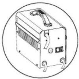
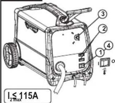
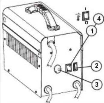
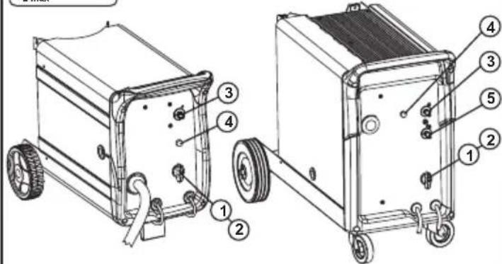
- DESCRIPTION OF THE WELDING MACHINE CONTROL, ADJUSTMENT AND CONNECTION DEVICES
Fig. B1, B2
5. INSTALLATION

WARNING!
CARRY OUT ALL INSTALLATION OPERATIONS AND ELECTRICAL CONNECTIONS WITH THE WELDING MA COMPLETELY SWITCHED OFF AND DISCONNECTED THE POWER SUPPLY OUTLET.
THE ELECTRICAL CONNECTIONS MUST BE MADE ONLY AND EXCLUSIVELY BY AUTHORISED OR QUALIFIED PERSONNEL.
PREPARATION
Fig. C
Unpack the welding machine, assemble the separate parts contained in the package.
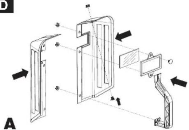
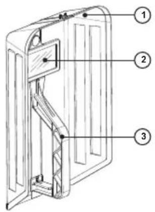
Assembling the protective mask
Fig. D
Assembling the return cable-clamp
Fig. E
HOW TO LIFT THE WELDING MACHINE
None of the welding machines described in this manual is equipped with a lifting device.
SITE
Locate the welding machine in an area where openings for cooling air are not obstructed (forced circulation with fan), leave at least 250mm free space around the welding machine; check that conductive dusts, corrosive vapours, humidity etc., will not enter welding machine.

WARNING! Position the welding machine on a flat with sufficient carrying capacity for its weight, to it from tipping or moving hazardously.
CONNECTION OF PLUG AND SOCKET (only applicable to models supplied without plug): connect a normalised plug (2P + DIn for 1ph, 3P + T for 3ph) having sufficient capacity- to the power cable and prepare a mains outlet fitted with fuses or an automatic circuit-breaker; the special earth terminal should be connected to
the earth conductor (yellow-green) of the power supply line. Table 1 (TAB.1) shows the recommended delayed fuse sizes in amps, chosen according to the max. nominal current supplied by the welding machine, and the nominal voltage of the main power supply.
- To carry out voltage change operations(only the 3-phase version), take off the panel to gain access to the inside of the machine, and prepare the voltage change terminal board so that the connection indicated on the special indicator plate corresponds to the available power supply voltage.
Fig. F
Reassemble the panel carefully using the appropriate screws. Warning!
In the factory the machine is set at the highest voltage of the available range, e.g.
U, 400V <= Voltage setting at the factory.
CONNECTION TO THE MAIN POWER SUPPLY
- Before making any electrical connection, make sure the rating data of the welding machine correspond to the mains voltage and frequency available at the place of installation.
- The welding machine should only be connected to a power supply system with the neutral conductor connected to earth.
- To ensure protection against indirect contact use residual current devices of the following types:
- Type A ( ∼ ) for single phase machines;
- Type B ( ) for 3-phase machines.
- To comply with the requirements of the EN 61000-3-11 (Flicker) standard we recommend connecting the welding machine to interface points of the power supply that have an impedance of less than Zmax = 0.1 ohm.
- the welding machine falls within the requisites of IEC/EN 61000-3-12 standard.

WARNING!
Failure to observe the above rules will make the (Class 1) safety system installed by the manufacturer ineffective with consequent serious risks to persons (e.g. electric shock) and - objects (e.g. fire).
CONNECTION OF THE WELDING CABLES

WARNING! BEFORE MAKING THE FOLLOWING
CONNECTIONS MAKE SURE THE WELDING MACHINE IS SWITCHED OFF AND DISCONNECTED FROM THE POWER SUPPLY OUTLET.
Table 1 (TAB. 1) gives the recommended values for the welding cables (in mm ^2 ) depending on the maximum current supplied by the welding machine.
Connection to the gas bottle (if used)
- Gas bottle can be loaded on welding machine bottle support platform: max 20 kg.
- Screw the pressure reducing valve(*) onto the gas bottle valve, inserting the appropriate adapter supplied as an accessory, for when the gas used is Argon or an Argon /CO₂ mixture.
- Connect the gas inlet pipe to the pressure-reducing valve and tighten the band supplied.
- Loosen the adjustment ring nut on the pressure-reducing valve before opening the bottle valve.
(*) Accessory to be purchased separately if not supplied with the product.
Connecting the welding current return cable
This is connected to the piece being welded or to the metal bench supporting it, as close as possible to the join being made.
Connecting the torch (only for versions with EURO connector)
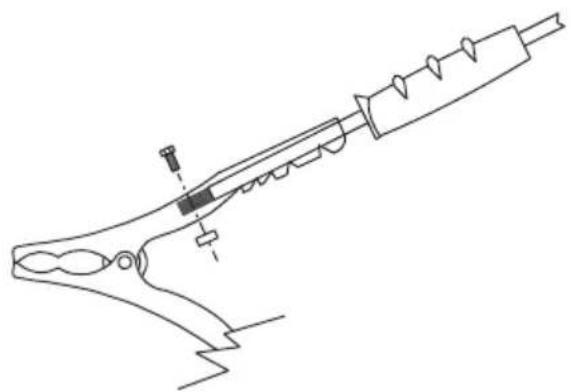
Engage the torch with its dedicated connector by tightening the locking ring manually as far down as it will go. Prepare the wire for loading the first time by dismantling the nozzle and the contact tube to ease its exit.
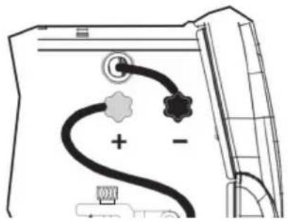
Changing the polarity
- Open the reel compartment door.
-
MIG/MAG welding (gas):
-
Connect the torch cable from the wire feeder to the red terminal (+).
- Connect the clamp return cable to the black terminal (-).
- FLUX welding (no gas):
- Connect the torch cable from the wire feeder to the black terminal (-).
- Connect the clamp return cable to the red terminal (+).
- Close the reel compartment door.
LOADING THE WIRE REEL (Fig. H)

WARNING! BEFORE STARTING THE OPERATIONS
TO LOAD THE WIRE MAKE SURE THE WELDING MACHINE IS SWITCHED OFF AND DISCONNECTED FROM THE MAIN POWER SUPPLY OUTLET.
MAKE SURE THAT THE WIRE FEEDER ROLLERS, THE WIRE GUIDE HOSE AND THE CONTACT TIP OF THE TORCH MATCH THE DIAMETER AND TYPE OF WIRE TO BE USED AND MAKE SURE THAT THESE ARE FITTED CORRECTLY. WHEN INSERTING AND THREADING THE WIRE DO NOT WEAR PROTECTIVE GLOVES.
- Open the reel compartment door.
- Position the wire reel on the spindle, holding the end of the wire upwards; make sure the tab for pulling the spindle is correctly seated in its hole (1a).
- Release the pressure counter-roller(s) and move them away from the lower roller(s) (2a-b);
- Make sure that the towing roller(s) is suited to the wire used (2c).
- Free the end of the wire and remove the distorted end with a clean cut and no burr; turn the reel anti-clockwise and thread the end of the wire into the wire-guide infeed, pushing it 50-100mm into the wire guide of the torch fitting (2d).
-
Re-position the counter-roller(s), adjusting the pressure to an 1)intermediate value, and make sure that the wire is correctly positioned in the groove of the lower roller(s) (3)
-
Use the adjustment screw located at the centre of the spindle to apply a slight braking pressure on the spindle itself (1b).
- Remove the nozzle and contact tip (4a).
- Insert the welding machine plug in the power supply outlet, switch on the welding machine, press the torch button and wait for the end of the wire to pass through the whole of the wire guide hose and protrude by 10-15 cm from the front part of the torch, release the button.

WARNING! During these operations the wire is live and
subject to mechanical stress; therefore if adequate precautions are not taken the wire could cause hazardous electric shock, injury and striking of electric arcs:
- Do not direct the mouthpiece of the torch towards parts of the body.
- Keep the torch away from the gas bottle.
- Re-fit the contact tip and the nozzle onto the torch (4b).
- Check that wire feed is regular; set the roller and spindle braking pressure to the minimum possible values making sure that the wire does not slide in the groove and when feed is halted the loops of wire are not loosened by excessive reel inertia.
- Cut the end of the wire so that 10-15 mm protrude from the nozzle.
- Close the reel compartment door.
6. WELDING: DESCRIPTION OF THE PROCEDURE
- Connect the return cable to the piece to be welded.
- Check the polarity (only for FLUX versions).
- If solid wire is used, open and adjust the flow of shielding gas by means of the pressure reducer.
NOTE: remember to shut the shielding gas off when you finish work.
- Switch the welder on and set the welding current by means of the switches or rotary switch (if any).
Fig. I
- To start welding press the torch button.
- To adjust the welding parameters adjust the wire feed rate (where provided) using the appropriate knob until even welding is obtained (Fig. B-3).
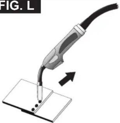
SPOT WELDING FUNCTION (where provided) Fig. L
- To change the welding time operate the adjustment knob (Fig. B-5).

WARNING:
- In some models the wireguide tip is normally live; take care to prevent unwanted strikes.
- The indicator light comes on when there is overheating and cuts off the power supply; it will reset automatically within a few minutes, after cooling down.
7. MAINTENANCE

WARNING! BEFORE CARRYING OUT MAINTENANCEOPERATIONS MAKE SURE THE WELDING MACHINE IS SWITCHED OFF AND DISCONNECTED FROM THE MAIN POWER SUPPLY.
ROUTINE MAINTENANCE: ROUTINE MAINTENANCE OPERATIONS CAN BE CARRIED OUT BY THE OPERATOR.
Torch
- Do not put the torch or its cable on hot pieces; this would cause the insulating materials to melt, making the torch unusable after a very short time;
- Make regular checks on the gas pipe and connector seals;
- Every time the wire reel is changed, blow out the wire-guide hose using dry compressed air (max. 5 bar) to make sure it is not damaged;
- Before every use, check the wear and correct assembly of the parts at the end of the torch: nozzle, contact tip, gas diffuser.
- Make frequent checks on the state of wear of the wire feeder rollers, regularly remove the metal dust deposited in the feeder area (rollers and wire-guide infeed and outfeed).
Wire feeder
WARNING! BEFORE REMOVING THE WELDING MACHINE PANELS AND WORKING INSIDE THE MACHINE MAKE SURE THE WELDING MACHINE IS SWITCHED OFF AND DISCONNECTED FROM THE MAIN POWER SUPPLY OUTLET. If checks are made inside the welding machine while it is live, this may cause serious electric shock due to direct contact with live parts and/or injury due to direct contact with moving parts.
- Inspect the welding machine regularly, with a frequency depending on use and the dustiness of the environment, and remove the dust deposited on the transformer, reactance and rectifier using a jet of dry compressed air (max. 10 bar).
- Do not direct the jet of compressed air on the electronic boards; these can be cleaned with a very soft brush or suitable solvents.
- At the same time make sure the electrical connections are tight and check the wiring for damage to the insulation.
- At the end of these operations re-assemble the panels of the welding machine and screw the fastening screws right down.
- Never, ever carry out welding operations while the welding machine is open.
- After having carried out maintenance or repairs, restore the connections and wiring as they were before, making sure they do not come into contact with moving parts or parts that can reach high temperatures. Tie all the wires as they were before, being careful to keep the high voltage connections of the primary transformer
separate from the low voltage ones of the secondary transformer. Use all the original washers and screws when closing the casing.
(IT)
MANUALE ISTRUZIONE
ATTENZIONE:
PRIMA DI UTILIZZARE LA SALDATRICE LEGGERE ATTENTAMENTE IL MANUALE DI ISTRUZIONE.
SALDATRICI A FILO CONTINUO PER LA SALDATURA AD ARCO MIG/MAG E FLUX PREVISTE PER USO INDUSTRIALE E PROFESSIONALE.
MANUEL D'INSTRUCTIONS
ATTENTION! AVANT TOUTE UTILISATION DU POSTE DE SOUDAGE, LIRE ATTENTIVEMENT LE MANUEL D'INSTRUCTIONS.
POSTES DE SOUDAGE À FIL CONTINU POUR LE SOUDAGE À L'ARC MIG/MAG ET FLUX PRÉVUS POUR UNE UTILISATION INDUSTRIELLE ET PROFESSIONNELLE.
MANUAL DE INSTRUÇÕES
CUIDADO! ANTES DE UTILIZAR A MÁQUINA DE SOLDA CUIDADOSAMENTE O MANUAL DE INSTRUÇÕES !
MÁQUINAS DE SOLDA A FIO CONTÍNUO PARA A SOLDAGEM A ARCO MIG/MAG E FLUX PREVISTAS PARA USO INDUSTRIAL E PROFISSIONAL.
4. BESCHRIJVING VAN DE LASMACHINE
PLAATSING VAN DE LASMACHINE
LASMACHINE WEGNEEMT EN NAAR DE BINNENKANT ERVAN GAAT, MOET MEN CONTROLEREN OF DE LASMACHINE UITGESCHAKELD IS EN LOSGEKOPPELD IS VAN HET VOEDINGSNET.
MANUAL DE INSTRUCTIUNI
ATENȚIE: CITIȚI CU ATENȚIE ACEST MANUAL DE INSTRUCTIUNI ÎNAINTE DE FOLOSIREA APARATULUI DE SUDURĂ!
APARAT DE SUDURĂ CU SĂRMĂ CONTINUĂ PENTRU SUDURA CU ARC MIG/MAG ȘI FLUX DESTINAT UZULUI INDUSTRIAL ȘI PROFESIONAL.
2. INLEDNING OCH ALLMÄN BESKRIVNING
ALMINDELIG VEDLIKEHOLD:
ALMINDELIGE VEDLIKEHOLDSOPERASJONER KAN FULLF∅RES AV OPERAT∅REN.
Sveisebrenner
EKSTRAORDINÆRT VEDLIKEHOLD
ALT EKSTRAORDINÄERT VEDLIKEHOLD FÅR KUN UTF∅RES AV PERSONELL MED ERFARING ELLER KVALIFIKASJONER I ELEKTRISKE OG MEKANISKE OMRÅDER, I SAMSVAR MED DE TEKNISKE STANDARDENE IEC/EN 60974-4.

ADVARSEL: FJERN ALDRI DEKSLER ELLER UTF∅R ARBEID INNE I ENHETEN DERSOM DEN IKKE ER FRAKOPLET
STR∅MNETTET.
text_image
REM F SAFE2. UVOD IN SPLOŠEN OPIS
Ta varilni aparat je izvor energije za obločno varjenje, izdelan je posebej za varjenje MAG za legirana ali malolegirana jekla, šibko legirana s CO 2 , ali mešanicami Argon/CO 2 . Pri tem uporablja
elektrodne polne ali žice z jedrom (cevne).
KEEVITUSAPARAADI TÖSTMINE
KEEVITAJA VÕIB TEOSTADA NORMAALSEID HOOLDUSTÕID.
Põleti
NADZWYCZAJNA KONSERWACJA
OPERACJE NADZWYCZAJNEJ KONSERWACJI MUSZA BYĆ WYKONYWANE WYŁĄCZNIE PRZEZ PERSONEL DOŚWIADCZONY LUB WYKWALIFIKOWANY W ZAKRESIE ELEKTRYCZNO-MECHANICZNYM, ZGODNIE Z NORMA TECHNICZNA IEC/EN 60974-4.

text_image
FUSE T A 10 11TAB. 1
WELDING MACHINE TECHNICAL DATA - DATI TECNICI SALDATRICE
natural_image
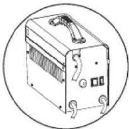
Line drawing of a portable electronic device with ventilation slots and a handle, enclosed in a circle (no text or symbols)| MODEL | |||||||||
| I_2 max (A) | 100V | 115V | 230V | 100V | 115V | 230V | mm ^2 | kg | dB(A) |
| 80 | T20A | T16A | T10A | 32A | 16A | 16A | 6 | 13 | <85 |
| MODEL | ||||||||
| I_2 max (A) | 230V | 400V | 230V | 400V | mm2 | kg | dB(A) | |
| 1~ | 80 | T10A | - | 16A | - | 10 | 20 | <85 |
| 105 | T10A | - | 16A | - | 10 | 21 | <85 | |
| 115 | T16A | - | 16A | - | 10 | 25 | <85 | |
| 140 | T16A | - | 16A | - | 16 | 40 | <85 | |
| 180 | T20A | - | 32A | - | 16 | 45 | <85 | |
| 200 | T32A | - | 32A | - | 16 | 53 | <85 | |
| 235 | T32A | - | 32A | - | 25 | 60 | <85 | |
| 1~2~ | 180 | T16A | - | 16A | - | 16 | 39 | <85 |
| - | T16A | - | 16A | |||||
| 3~ | 140 | - | T10A | - | 16A | 16 | 46 | <85 |
| 160 | T10A | T6A | 16A | 16A | 16 | 45 | <85 | |
| 200 | T16A | T10A | 16A | 16A | 16 | 50 | <85 | |
TAB. 2
MIG TORCH TECHNICAL DATA ACCORDING TO EN 60974-7 - DATI TECNICI TORCIA MIG IN ACCORDO ALLA EN 60974-7
natural_image
Line drawing of a portable electronic device with ventilation slots and control knobs, enclosed in a circular frame (no text or symbols)| VOLTAGE CLASS: 113V | |||
| I max (A) X (%) | [2X0X] | [X84X] | 0mm↑ |
| 70 35 NO GAS | FLUX CORED: 0.8 ÷ 0.9 | ||
| MODEL | VOLTAGE CLASS: 113V | |||
| I_2 max (A) I max (A) X (%) | [×××] | [×××] | ||
| 80 105 35 | Ar CO | _2/CO_2 | STEEL: 0.6 ÷ 1 AL: 0.8 ÷ 1 INOX: 0.8FLUX CORED: 0.8 ÷ 1.2 | |
| 105 105 35 | Ar CO | _2/CO_2 | ||
| 105 ÷ 115 | 115 35 Ar CO | _2/CO_2 | ||
| 90 35 NO GAS | ||||
| 140 | 140 35 Ar CO | _2/CO_2 | ||
| 115 35 NO GAS | ||||
| 160 ÷ 180 ÷ 200 | 150 60 Ar CO | _2 | STEEL: 0.6 ÷ 1 AL: 0.8 ÷ 1 INOX: 0.8 | |
| 180 60 CO | _2 | |||
| 235 | 200 60 Ar CO | _2 | STEEL: 0.6 ÷ 1.2 AL: 0.8 ÷ 1 INOX: 0.8 ÷ 1 | |
| 230 60 CO | _2 | |||
FIG. B1
text_image
I₂≤115A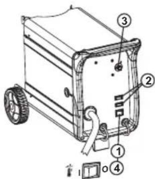
text_image
Technical diagram of a portable electrical box with numbered parts and labeled connectors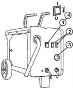
text_image
Technical diagram of a portable device with numbered components and labeled partsFIG. B2
text_image
Technical diagram of an electronic device with numbered components and labeled partsI_2≥140A
text_image
Technical diagram of a two-wheeled cart with numbered components for identification1- Main switch (EN)
2-Arc voltage adjustment
3- Wire feed rate (if any)
4- Thermostat trigger light
5- Welding time (models with I_2 ≥ 140A )
1- Interruptor general (ES)
natural_image
Technical line drawing of a robotic device with labeled parts and directional arrows indicating assembly (no text or symbols present)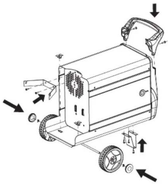
text_image
Technical diagram of a mobile phone driver with labeled parts and directional arrows indicating assembly or maintenance.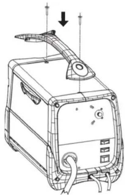
natural_image
Technical line drawing of a portable electronic device with control panel and antenna (no text or symbols)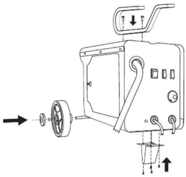
text_image
Technical diagram of a mechanical device with labeled parts and directional arrows indicating assembly or movement.
natural_image
Technical line drawing of a portable electric heater with wheels and control panel (no text or symbols)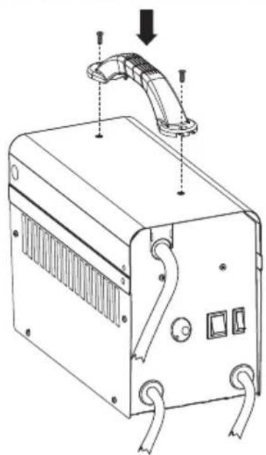
natural_image
Line drawing of a portable electronic device with attached tubing and control panel (no text or symbols)FIG. D
text_image
Technical diagram of a mechanical assembly with labeled components and directional arrows indicating movement or assembly.B
text_image
Technical diagram of a door frame with numbered components for identification| 1- MASK2- FILTER3- HANDGRIP | 1- LASKAP2- LASGLAS3- HANDGREEP | 1- NAAMARI2- SUODATIN3- KÄSIKAHVA | 1- MACKA2- ФИЛЬТР3- РУКОЯТКА | 1- OCHRANNÝ ŠTÍT2- FILTR3- RUKOJET | 1- APSAUGINE KAUKE2- FILTRAS3- RANKENA |
| 1- MASCHERA2- FILTRO3- IMPUGNATURA | 1- MASCARA2- FILTRO3- EMPUÑADURA | 1- MASKE2- FILTER3- HÄNDTAK | 1- MASZK2- SZURO3- NYÉL | 1- OCHRANNÝ ŠTÍT2- FILTER3- RUKOVÄT | 1- KEEVITUSKILP2- FILTER3- KÄEPIDE |
| 1- MASQUE2- FILTRE3- POIGNÉE | 1- MASCARA2- FILTRO3- PUNHO | 1- MASK2- FILTER3- HANDTAG | 1- MASCA2- FILTRU3- MÄNER | 1- ZAŠCITNA MASKA2- FILTER3- DRŽALO | 1- MASKA2- FILTRS3- ROKTURIS |
| 1- MASKE2- FILTER3- HANDGRIFF | 1- MASKE2- FILTER3- HÄNDGREB | 1- MAŞKA2- ФІАТРО3- ΛΑΒΗ | 1- MASKA SPAWALNICZA2- FILTR3- UCHWYT | 1- MASKA2- FILTER3- DRŽAC | 1- MACKA2- ФИЛТЬР3- РЪКОХВАТКА |
FIG. E
natural_image
Line drawing of a mechanical tool or device with no visible text, numbers, or symbols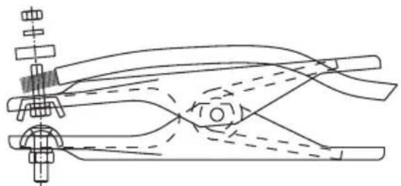
natural_image
Technical line drawing of a mechanical clamp or clamping device with no visible text or symbols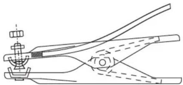
natural_image
Technical line drawing of a mechanical clamp or clamp assembly (no text or symbols)FIG. F
400V
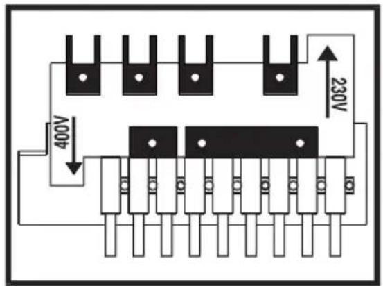
text_image
400V 230V230V
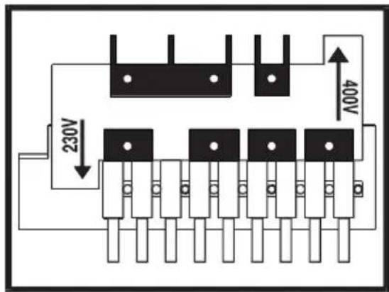
text_image
230V 400VFIG. G
natural_image
Diagram of a car air conditioner system with no visible text or symbols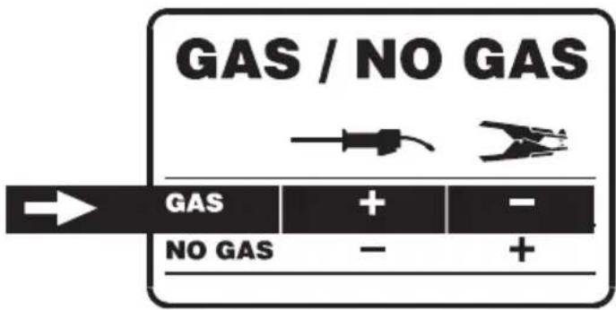
natural_image
Diagram of a car air conditioner unit with labeled components and wiring (no text or symbols)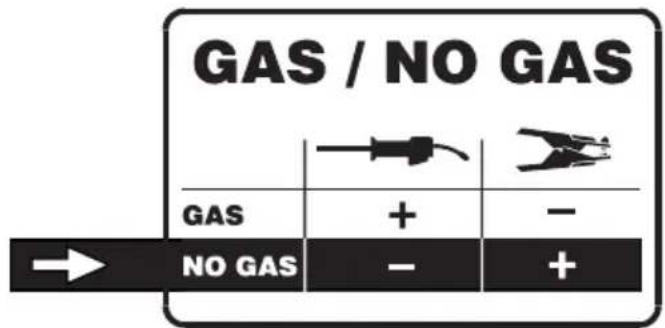
text_image
① ∅ 100mm a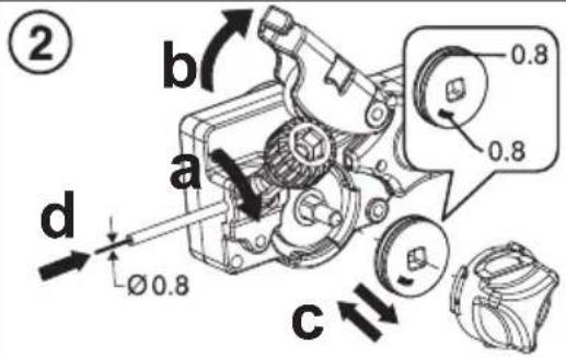
text_image
② b a 0.8 0.8 d Ø 0.8 c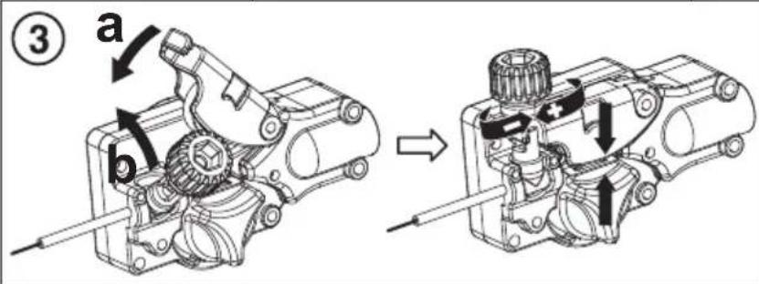
text_image
③ a b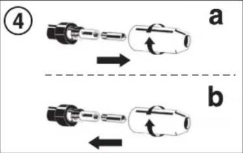
text_image
④ a b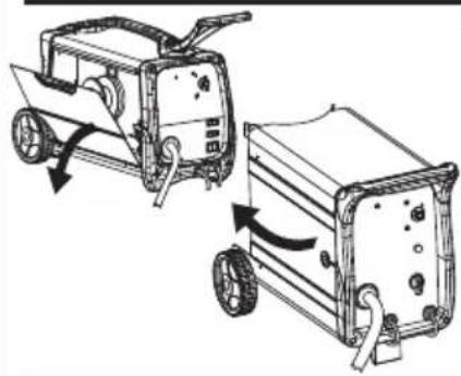
natural_image
Diagram of a mechanical device with two wheels and directional arrows indicating motion (no text or symbols)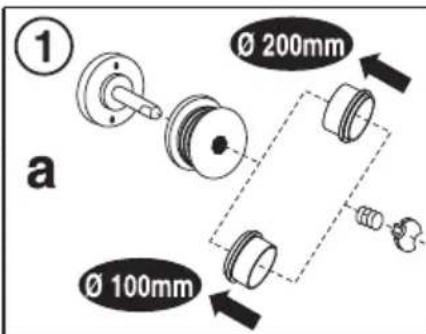
text_image
① Ø 200mm Ø 100mm a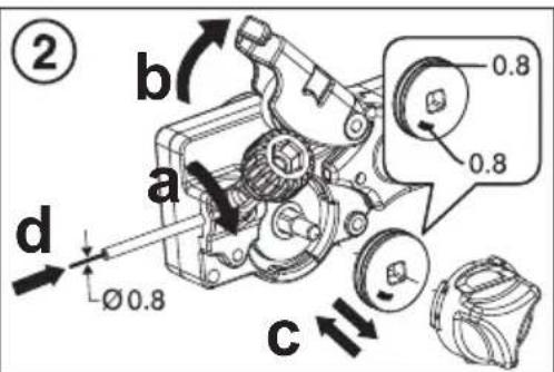
text_image
② b a 0.8 0.8 d Ø 0.8 c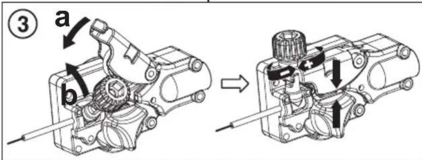
text_image
③ a b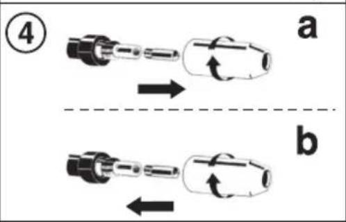
text_image
④ a b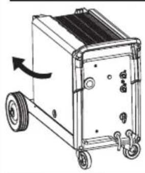
natural_image
Line drawing of a wheeled cart with wheels and a directional arrow indicating motion (no text or symbols)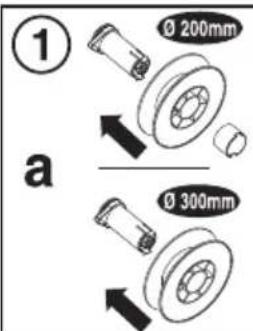
text_image
① Ø 200mm a Ø 300mm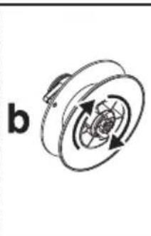
natural_image
Mechanical component diagram showing a rotating wheel with gear and shaft (no text or symbols)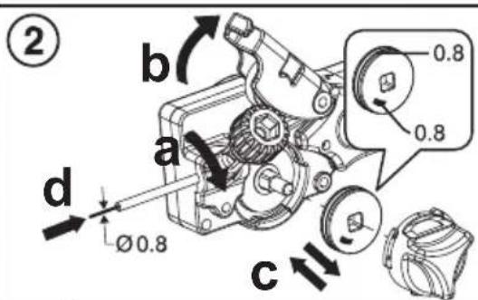
text_image
② b a 0.8 0.8 d Ø 0.8 c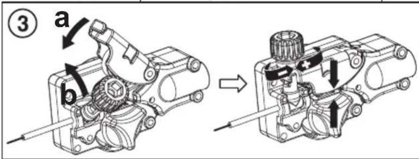
text_image
③ a b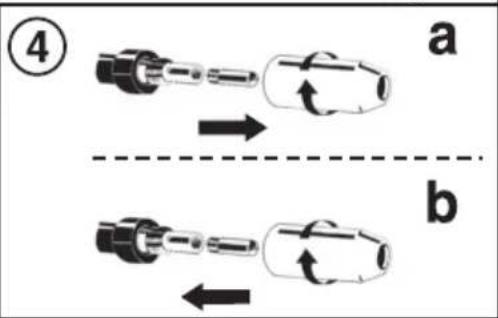
text_image
④ a bFIG. I
WELDING MACHINES OUTPUT CURRENT VERSUS SWITCH POSITIONS - REGOLAZIONE DELLA CORRENTE DI USCITA DELLA SALDATRICE
| [2DH7] | I2 max(A) | 1MIN MIN MAX MAX | 2 | 1 | 2 | 8SPEEDm/min | |
| 80A | 55A | 60A | 70A | 80A(max 100A) | 2 - 13 | ||
| 105A | 50A | 65A | 85A | 105A(max 120A) | |||
| 115A | 30A | 55A | 85A | 115A(max 145A) | |||
| I_2 max (A) | 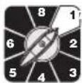 | 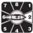 | 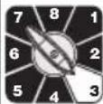 | 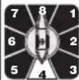 | 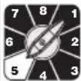 | 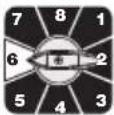 |  | 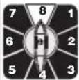 | 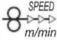 | |
| 140 | 30A 50A 70A | 90A 110 | 140A | (max 170A) | ---- ---- | 2 - 13 | ||||
| 180 | 30A 50A 85A | 110A 155A | 180A | (max 220A) | ---- ---- | |||||
| 200 | 40A 55A 70A | 90A 115A | 140A | 170A 200A(max 240A) | ||||||
| 235 | 40A 60A 80A | 100A 125A | 160A 195A | 235A | (max 270A) | |||||
| 140 | 45A 70A 90A | 120A 140A | (max 180A) | ---- ---- | 2 - 203 | |||||
| 160 | (max 200A) | ---- ---- | ||||||||
| 200 | 40A 55A 90A | 120A 160A | 200A | (max 260A) | ---- ---- | |||||
FIG. L
natural_image
Illustration of a welding torch applying material to a surface, with an arrow indicating the process (no text or symbols present)(EN) Spot-welding can be carried out on overlapped metal sheet with a maximum thickness of 0.8 mm.
natural_image
Illustration of a welding torch applying material to a surface, with an arrow indicating the process (no text or symbols present)(EN) On two overlapped metal sheets.
(NO) Med to overlappede metallplater.
natural_image
Illustration of a welding torch applying material to a surface, with an arrow indicating the process (no text or symbols present)(EN) On two overlapped and drilled metal sheets.
natural_image
3D illustration of a person performing a manual press or cable handling equipment (no text or symbols visible)(EN) GUARANTEE
The manufacturer guarantees proper operation of the machines and undertakes to replace free of charge any parts should they be damaged due to poor quality of materials or manufacturing defects within 12 months of the date of commissioning of the machine, when proven by certification. Returned machines, also under guarantee, should be dispatched CARRIAGE PAID and will be returned CARRIAGE FORWARD. This with the exception of, as decreed, machines considered as consumer goods according to European directive 1999/44/EC, only when sold in member states of the EU. The guarantee certificate is only valid when accompanied by an official receipt or delivery note. Problems arising from improper use, tampering or negligence are excluded from the guarantee. Furthermore, the manufacturer declines any liability for all direct or indirect damages.