Infinity 150 - Welding machine Telwin - Free user manual and instructions
Find the device manual for free Infinity 150 Telwin in PDF.
| Product Type | MMA welding machine (coated electrode) |
| Technology | IGBT transistor inverter |
| Supply voltage | 230 V single-phase (Dual Voltage Automatic model: 115/230 V with automatic detection) |
| Welding current range | 25 - 150 A |
| Duty cycle (at 40°C) | 60% at 150 A, 100% at 90 A |
| Recommended electrode diameters | 1.6 - 4.0 mm |
| Thermal protection | Automatic shutdown in case of overheating |
| Anti-stick protection | Automatic detection and blocking in case of electrode sticking |
| Overvoltage/undervoltage protection | Yes, blocking if voltage outside ±15% range |
| Weight | Approximately 6 kg |
| Dimensions (L x W x H) | 350 x 200 x 300 mm |
| Protection rating | IP21S (protection against water splashes and solid objects) |
| Routine maintenance | Internal dust removal with dry compressed air (max 10 bar); check electrical connections |
| Cleaning of electronic circuits | Soft brush or suitable solvents; avoid direct air jet |
| User safety | Galvanic isolation, protection against indirect contacts, welding mask mandatory |
| Supplied accessories | Power cable with plug, user manual; electrode holder and ground cable optional |
| Available spare parts | Electrode holders, cables, quick connectors, fuses, gaskets |
| Repairability | Telwin technical assistance; use of original parts recommended |
| Warranty | 12 months from commissioning (according to certificate) |
| Additional information | Compliant with standards EN 60974-1 and EN 60974-9 |
Frequently Asked Questions - Infinity 150 Telwin
User questions about Infinity 150 Telwin
0 question about this device. Answer the ones you know or ask your own.
Ask a new question about this device
Download the instructions for your Welding machine in PDF format for free! Find your manual Infinity 150 - Telwin and take your electronic device back in hand. On this page are published all the documents necessary for the use of your device. Infinity 150 by Telwin.
USER MANUAL Infinity 150 Telwin
1. GENERAL SAFETY CONSIDERATIONS FOR ARC WELDING
The operator should be properly trained to use the welding machine safely and should be informed about the risks related to arc welding procedures, the associated protection measures and emergency procedures.
(Please refer to the applicable standard "EN 60974-9: Arc welding equipment. Part 9: Installation and Use).

- Avoid direct contact with the welding circuit: the no-load voltage supplied by the welding machine can be dangerous under certain circumstances.
- When the welding cables are being connected or checks and repairs are carried out the welding machine should be switched off and disconnected from the power supply outlet.
- Switch off the welding machine and disconnect it from the power supply outlet before replacing consumable torch parts.
- Make the electrical connections and installation according to the safety rules and legislation in force.
- The welding machine should be connected only and exclusively to a power source with the neutral lead connected to earth.
- Make sure that the power supply plug is correctly connected to the earth protection outlet.
- Do not use the welding machine in damp or wet places and do not weld in the rain.
- Do not use cables with worn insulation or loose connections.
- Do not weld on containers or piping that contains or has contained flammable liquid or gaseous products.
- Do not operate on materials cleaned with chlorinated solvents or near such substances.
- Do not weld on containers under pressure.
- Remove all flammable materials (e.g. wood, paper, rags etc.) from the working area.
- Provide adequate ventilation or facilities for the removal of welding fumes near the arc; a systematic approach is needed in evaluating the exposure limits for the welding fumes, which will depend on their composition, concentration and the length of exposure itself.
- Keep the gas bottle (if used) away from heat sources, including direct sunlight.

- Use adequate electrical insulation with regard to the electrode, the work piece and any (accessible) earthed metal parts in the vicinity. This is normally achieved by wearing gloves, shoes, head coverings and clothing designed for this purpose and by using insulating platforms or mats.
- Always protect your eyes with the relative filters, which must comply with UNI EN 169 or UNI EN 379, mounted on masks or use helmets that comply with UNI EN 175.
Use the relative fire-resistant clothing (compliant with UNI EN 11611) and welding gloves (compliant with UNI EN 12477) without exposing the skin to the ultraviolet and infrared rays produced by the arc; the protection must extend to other people who are near the arc by way of screens or non-reflective sheets.
- Noise: If the daily personal noise exposure (LEPd) is equal to or higher than 85 dB(A) because of particularly intensive welding operations, suitable personal protective means must be used (Tab. 1).


- The flow of the welding current generates electromagnetic fields
(EMF) around the welding circuit.
Electromagnetic fields can interfere with certain medical equipment (e.g. Pace-makers, respiratory equipment, metallic prostheses etc.). Adequate protective measures must be adopted for persons with these types of medical apparatus. For example, they must be forbidden access to the area in which welding machines are in operation.
This welding machine conforms to technical product standards for exclusive use in an industrial environment for professional purposes. It does not assure compliance with the basic limits relative to human exposure to electromagnetic fields in the domestic environment.
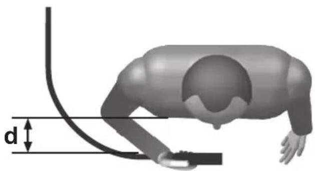
The operator must adopt the following procedures in order to reduce exposure to electromagnetic fields:
- Fasten the two welding cables as close together as possible.
- Keep head and trunk as far away as possible from the welding circuit.
- Never wind welding cables around the body.
- Avoid welding with the body within the welding circuit. Keep both cables on the same side of the body.
- Connect the welding current return cable to the piece being welded, as close as possible to the welding joint.
- Do not weld while close to, sitting on or leaning against the welding machine (keep at least 50 cm away from it).
- Do not leave objects in ferromagnetic material in proximity of the welding circuit.
- Minimum distance d=20 cm (Fig. I).

- Class A equipment:
This welding machine conforms to technical product standards for exclusive use in an industrial environment and for professional purposes. It does not assure compliance with electromagnetic compatibility in domestic dwellings and in premises directly connected to a low-voltage power supply system feeding buildings for domestic use.

EXTRA PRECAUTIONS
- WELDING OPERATIONS:
- In environments with increased risk of electric shock
- In confined spaces
- In the presence of flammable or explosive materials
MUST BE evaluated in advance by an "Expert supervisor" and must always be carried out in the presence of other people trained to intervene in emergencies.
All protective technical measures MUST be taken as provided in 7.10; A.8; A.10 of the applicable standard EN 60974-9: Arc welding equipment. Part 9: Installation and Use". - The operator MUST NOT BE ALLOWED to weld in raised positions unless safety platforms are used.
- VOLTAGE BETWEEN ELECTRODE HOLDERS OR TORCHES: working with more than one welding machine on a single piece or on pieces that are connected electrically may generate a dangerous accumulation of no-load voltage between two different electrode holders or torches, the value of which may reach double the allowed limit.
An expert coordinator must be designated to measuring the apparatus to determine if any risks subsist and suitable protection measures can be adopted, as foreseen by section 7.9 of the applicable standard "EN 60974-9: Arc welding equipment. Part 9: Installation and Use".

RESIDUAL RISKS
- IMPROPER USE: it is hazardous to use the welding machine for any work other than that for which it was designed (e.g. de-icing mains water pipes).
- Do not use the handle to hang the welding machine.
2. INTRODUCTION AND GENERAL DESCRIPTION
This welding machine is a power source for arc welding, made specifically for direct current (DC).
The specific characteristics of this regulation system (INVERTER), i.e. high speed and precise regulation, mean the welding machine gives excellent results when welding both with coated electrodes (rutile, acid, basic).
Regulation with the "inverter" system at the input of the power supply
line (primary) means there is a drastic reduction in the volume of both the transformer and the levelling reactance. This allows the construction of a welding machine with extremely reduced weight and volume, enhancing its advantages of easy handling and transportation.
OPTIONAL ACCESSORIES:
- MMA welding Kit.
3. TECHNICAL DATA DATA PLATE
The most important data regarding use and performance of the welding machine are summarised on the rating plate and have the following meaning:
Fig. A
1- Protection rating of the covering.
2- Symbol for power supply line:
1\~: single phase alternating voltage;
3- Symbol S: indicates that welding operations may be carried out in environments with heightened risk of electric shock (e.g. very close to large metallic volumes).
4- Symbol for welding procedure provided.
5- Symbol for internal structure of the welding machine.
6- EUROPEAN standard of reference, for safety and construction of arc welding machines.
7- Manufacturer's serial number for welding machine identification (indispensable for technical assistance, requesting spare parts, discovering product origin).
8- Performance of the welding circuit:
- U _0 : maximum no-load voltage.
- I_2/U_2 : current and corresponding normalised voltage that the welding machine can supply during welding
- X : Duty cycle: indicates the time for which the welding machine can supply the corresponding current (same column). It is expressed as %, based on a 10 minutes cycle (e.g. 60% = 6 minutes working, 4 minutes pause, and so on).
If the usage factors (on the plate, referring to a 40^ C environment) are exceeded, the thermal safeguard will trigger (the welding machine will remain in stand-by until its temperature returns within the allowed limits).
- A/V-A/V: shows the range of adjustment for the welding current (minimum-maximum) at the corresponding arc voltage.
9- Technical specifications for power supply line:
- U _1 : Alternating voltage and power supply frequency of welding machine (allowed limit ±10%):
- I 1max: Maximum current absorbed by the line.
- I _1eff : effective current supplied.
10- : Size of delayed action fuses to be used to protect the power line.
11- Symbols referring to safety regulations, whose meaning is given in chapter 1 "General safety considerations for arc welding".
Note: The data plate shown above is an example to give the meaning of the symbols and numbers; the exact values of technical data for the welding machine in your possession must be checked directly on the data plate of the welding machine itself.
OTHER TECHNICAL DATA
- WELDING MACHINE:
- see table 1 (TAB.1)
- %USE AT 20°C (if present on the top cover of the welding machine) USE AT 20°C, it gives, for each diameter (∅ ELECTRODE), the number of weldable electrodes within an interval of 10 minutes (ELECTRODES 10 MIN) at 20°C with a pause of 20 seconds for each electrode change; this datum is given also in percentage (%USE) which is the value in comparison with the maximum number of weldable electrodes.
- ELECTRODE HOLDER CLAMP: see table 2 (TAB.2)
The weight of the welding machine is given in the table 1 (TAB.1)
4. DESCRIPTION OF THE WELDING MACHINE
The unit is comprised of power modules which have been developed on a specially printed circuit designed to maximise reliability and reduce maintenance.
Fig. B
1- Power supply input (1\~), rectifier group and balancing capacitors.
2- Transistors and drivers switching bridge (IGBT).
It turns the mains rectified voltage into high frequency alternate voltage and permits power regulation according to the current/voltage of the weld to be done.
3- High frequency transformer: the primary windings are fed by the voltage converted by Block 2, it has the function of adapting voltage and current to the values required by the arc welding procedure and, simultaneously, isolates the welding circuit from the mains.
4- Secondary rectifier bridge with inductance: this changes the alternate voltage/current supplied by the secondary windings into continuous current/voltage at a low wave-length.
5- Electronic and regulation board: this instantly checks the value of the welding current against that selected by the user, it modulates the commands of the IGBT drivers, which control Regulation. Determines the dynamic response of the current while the electrode melts (instantaneous short circuits), and supervises the safety systems.
The "DUAL VOLTAGE AUTOMATIC" model has a device that automatically recognises the power supply voltage (115V AC-230V AC) and sets up the machine for correct operation.
The user will be able to understand whether the machine power supply is 115V AC or 230V AC from the colour of the LED (Fig C (3)).
- GREEN LED shows that the machine is connected to a 230V AC power supply.
- ORANGE LED shows that the machine is connected to a 115V AC power supply.
During operation at 115V AC it is possible that prolonged and sizeable voltage surges will cause the machine to switch to 230V AC operation for safety.
In such circumstances, to resume welding, the machine must be switched off and on again.
Wait until the LED (Fig.C(3)) has gone out completely before switching on again.
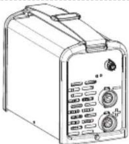
CONTROL, REGULATION AND CONNECTION DEVICES WELDING MACHINE
Front Panel
Fig. C
1- Positive quick plug (+) to connect welding cable.
2- YELLOW LED: normally off, when ON it means that the welding current cannot flow due to one of the following faults:
- Thermal protection: inside the machine the temperature is excessive. The machine is ON but does not deliver current until a normal temperature is reached. Once this happens the re-start is automatic.
- Mains over/undervoltage protection: the machine is blocked: the power supply voltage is 15% above or below the rating plate value. WARNING: Exceeding the upper voltage limit, as above, will cause serious damage to the device.
- ANTI STICK protection: automatically shuts down the welding machine if the electrode sticks to the material being welded so that it can be removed manually without damaging the electrode holder clamp.
3- GREEN LED: Connection to the mains, machine ready to work.
4- Potentiometer to regulate welding current with graduated scale in Amps, which also allows regulation during welding. (The "DUAL VOLTAGE AUTOMATIC" model has a double graduated Ampere scale).
5- Negative quick plug (-) to connect welding cable.
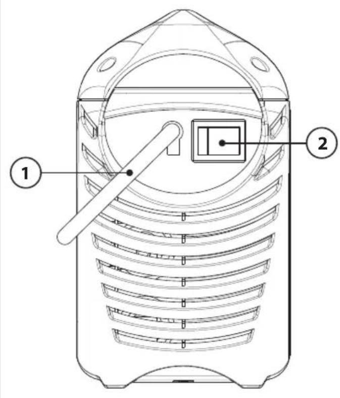
Back panel
Fig. D
1- Mains cable with E.E.C. 2p plug + ( ⏚ ). (For the "DUAL VOLTAGE AUTOMATIC" model the cable has no plug).
2- General luminous switch O/OFF - I/ON.
5. INSTALLATION

WARNING! CARRY OUT ALL INSTALLATION OPERATIONSAND ELECTRICAL CONNECTIONS WITH THE WELDING MACHINE COMPLETELY SWITCHED OFF AND DISCONNECTED FROM THE POWER SUPPLY OUTLET.
THE ELECTRICAL CONNECTIONS MUST BE MADE ONLY AND EXCLUSIVELY BY AUTHORISED OR QUALIFIED PERSONNEL.
PREPARATION
Unpack the welding machine, assemble the separate parts contained in the package.
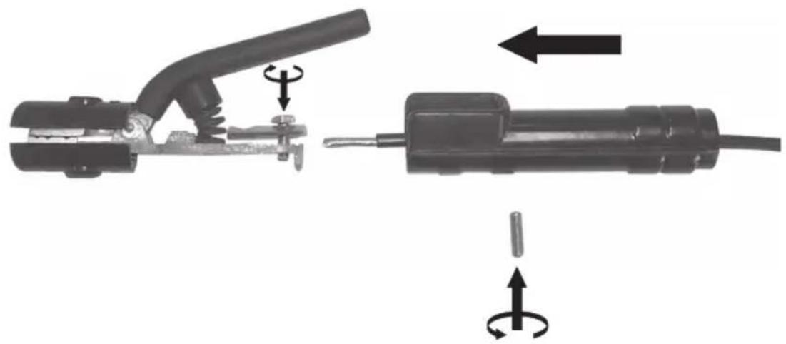
Assembling the return cable-clamp
Fig. E
Assembling the welding cable-electrode holder clamp Fig. F
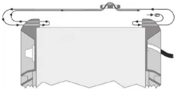
HOW TO LIFT THE WELDING MACHINE
All the welding machines described in this handbook should be lifted using the handle or strap supplied if provided for the particular model (fitted as described in FIG. L).
POSITION OF THE WELDING MACHINE
Choose the place to install the welding machine so that the cooling air inlets and outlets are not obstructed (forced circulation by fan, if present); at the same time make sure that conductive dusts, corrosive vapours, humidity etc. will not be sucked into the machine.
Leave at least 250mm free space around the welding machine.

WARNING! Position the welding machine on a flat surface with sufficient carrying capacity for its weight, to prevent it from tipping or moving hazardously.
CONNECTION TO THE MAIN POWER SUPPLY
- Before making any electrical connection, make sure the rating data of the welding machine correspond to the mains voltage and frequency available at the place of installation.
- The welding machine should only be connected to a power supply system with the neutral conductor connected to earth.
- To ensure protection against indirect contact use residual current devices of the following types:
- Type A ( ) for single phase machines;


) for 3-phase machines.
- To comply with the requirements of the EN 61000-3-11 (Flicker) standard we recommend connecting the welding machine to interface points of the power supply that have an impedance of less than:
Zmax = 0.47 ohm (80A).
Zmax = 0.24 ohm (130A - 170A).
Zmax = 0.17 ohm (200A).
- the welding machine does not fall within the requisites of IEC/EN 61000-3-12 standard.
Should it be connected to a public mains system, it is the installer's responsibility to verify that the welding machine itself is suitable for connecting to it (if necessary, consult the distribution network company).
- Unless otherwise specified (MPGE), the welding machines are compatible with power generating sets for voltage oscillations up to ± 15%.
For correct use, the power generating set must be brought to steady conditions before being able to connect the inverter.
- PLUG AND OUTLET:
- The 230V model is fitted at the factory with a power supply cable and normalised plug, (2P + T) 16A/250V.
It can therefore be connected to a mains outlet fitted with fuses or an automatic circuit-breaker; the special earth terminal should be connected to the earth conductor (yellow-green) of the power supply line.
Table (TAB.1) shows the recommended delayed fuse sizes in amps, chosen according to the max. nominal current supplied by the welding machine, and the nominal voltage of the main power supply.
- For welding machines without a plug (115/230V models), connect a normalised plug (2P + T) - having sufficient capacity- to the power cable and prepare a mains outlet fitted with fuses or an automatic circuit-breaker; the special earth terminal should be connected to the earth conductor (yellow-green) of the power supply line. Table (TAB. 1) shows the recommended delayed fuse sizes in amps, chosen according to the max. nominal current supplied by the welding machine, and the nominal voltage of the main power supply.

WARNING! Failure to observe the above rules will make the (Class 1) safety system installed by the manufacturer ineffective with consequent serious risks to persons (e.g. electric shock) and objects (e.g. fire).
CONNECTION OF THE WELDING CABLES

WARNING! BEFORE MAKING THE FOLLOWING
CONNECTIONS MAKE SURE THE WELDING MACHINE IS SWITCHED OFF AND DISCONNECTED FROM THE POWER SUPPLY OUTLET.
Table (TAB. 1) gives the recommended values for the welding cables (in mm ^2 ) depending on the maximum current supplied by the welding machine.
MMA WELDING
Almost all coated electrodes are connected to the positive pole (+) of the power source; as an exception to the negative pole (-) for acid coated electrodes.
WELDING OPERATIONS WITH DIRECT CURRENT
Connecting the electrode-holder clamp welding cable
On the end take a special terminal that is used to close the uncovered part of the electrode.
This cable is connected to the terminal with the symbol (+).
Connecting the welding current return cable
This is connected to the piece being welded or to the metal bench supporting it, as close as possible to the join being made.
This cable is connected to the terminal with the symbol (-).
Warnings:
- Turn the welding cable connectors right down into the quick connections (if present), to ensure a perfect electrical contact; otherwise the connectors themselves will overheat, resulting in their rapid deterioration and loss of efficiency.
- The welding cables should be as short as possible.
- Do not use metal structures which are not part of the workpiece to substitute the return cable of the welding current: this could jeopardise safety and result in poor welding.
6. WELDING: DESCRIPTION OF THE PROCEDURE
- It is most important that the user refers to the maker's instructions indicated on the stick electrode packaging. This will indicate the correct polarity of the stick electrode and the most suitable current.
- The welding current must be regulated according to the diameter of the electrode in use and the type of the joint to be carried out: see below the currents corresponding to various electrode diameters:
| ∅ Electrode (mm) | Welding current (A) | |
| min. max. | ||
| 1.6 25 50 | ||
| 2 | 40 80 | |
| 2.5 60 | 110 | |
| 3.2 80 | 160 | |
| 4 | 120 | 200 |
- The user must consider that, according to the electrode diameter, higher current values must be used for flat welding, whereas for vertical or overhead welds lower current values are necessary.
- As well as being determined by the chosen current intensity, the mechanical characteristics of the welded join are also determined by the other welding parameters i.e. arc length, working rate and position, electrode diameter and quality (to store the electrodes correctly, keep them in a dry place protected by their packaging or containers).
Procedure
- Holding the mask IN FRONT OF THE FACE, strike the electrode tip on the workpiece as if you were striking a match. This is the correct strike-up method.
WARNING: do not hit the electrode on the workpiece, this could damage the electrode and make strike-up difficult.
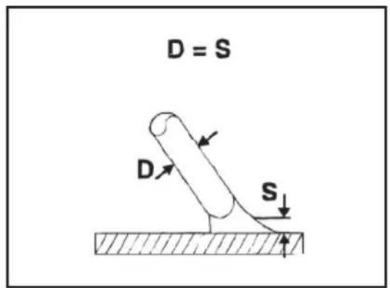
- As soon as arc is ignited, try to maintain a distance from the workpiece equal to the diameter of the electrode in use. Keep this distance as much constant as possible for the duration of the weld. Remember that the angle of the electrode as it advances should be of 20-30 grades (Fig. G).
- At the end of the weld bead, bring the end of the electrode backward, in order to fill the weld crater, quickly lift the electrode from the weld pool to extinguish the arc.
7. MAINTENANCE

WARNING! BEFORE CARRYING OUT MAINTENANCE ONS MAKE SURE THE WELDING MACHINE IS SWITCHED OFF CONNECTED FROM THE MAIN POWER SUPPLY.
WARNING! BEFORE REMOVING THE WELDING MACHINE AND WORKING INSIDE THE MACHINE MAKE SURE THE G MACHINE IS SWITCHED OFF AND DISCONNECTED FROM N POWER SUPPLY OUTLET.
If checks are made inside the welding machine while it is live, this may cause serious electric shock due to direct contact with live parts and/or injury due to direct contact with moving parts.
- Inspect the welding machine regularly, with a frequency depending on use and the dustiness of the environment, and remove the dust deposited on the transformer, reactance and rectifier using a jet of dry compressed air (max. 10bar).
- Do not direct the jet of compressed air on the electronic boards; these can be cleaned with a very soft brush or suitable solvents.
- At the same time make sure the electrical connections are tight and check the wiring for damage to the insulation.
- At the end of these operations re-assemble the panels of the welding machine and screw the fastening screws right down.
- Never, ever carry out welding operations while the welding machine is open.
- After having carried out maintenance or repairs, restore the connections and wiring as they were before, making sure they do not come into contact with moving parts or parts that can reach high temperatures. Tie all the wires as they were before, being careful to keep the high voltage connections of the primary transformer separate from the low voltage ones of the secondary transformer.
Use all the original washers and screws when closing the casing.
8. TROUBLESHOOTING
IN CASE OF UNSATISFACTORY FUNCTIONING, BEFORE SERVICING MACHINE OR REQUESTING ASSISTANCE, CARRY OUT THE FOLLOWING CHECK:
- Check that the welding current, which is regulated by the potentiometer with a graduated amp scale, is correct for the diameter and electrode type in use.
- Check that when general switch is ON the relative lamp is ON. If this is not the case then the problem is located on the mains (cables, plugs, outlets, fuses, etc.)
- Check that the yellow led (ie. thermal protection interruption- either over or undervoltage or short circuit) is not lit.
- Check that the nominal intermittance ratio is correct. In case there is a thermal protection interruption, wait for the machine to cool down, check that the fan is working properly.
- Check the mains voltage: if the value is too high or too low the welding machine will be stopped.
- Check that there is no short-circuit at the output of the machine: if this is the case eliminate the incovenience.
- Check that all connections of the welding circuit are correct, particularly that the work clamp is well attached to the workpiece, with no interfering material or surface-coverings (ie. Paint).
- Protective gas must be of appropriate type (Argon 99.5%) and quantity.
(IT)
MANUALE ISTRUZIONE

ATTENZIONE! PRIMA DI UTILIZZARE LA SALDATRICE LEGGERE ATTENTAMENTE IL MANUALE DI ISTRUZIONE.
1. SICUREZZA GENERALE PER LA SALDATURA AD ARCO
Zmax = 0.47 ohm (80A).
Zmax = 0.24 ohm (130A - 170A).
Zmax = 0.17 ohm (200A).
MANUEL D'INSTRUCTIONS

ATTENTION! AVANT TOUTE UTILISATION DU POSTE DE SOUDAGE, LIRE ATTENTIVEMENT LE MANUEL D'INSTRUCTIONS.
1. RÈGLES GÉNÉRALES DE SÉCURITÉ POUR LA SOUDURE À L'ARC
Zmax = 0.47 ohm (80A).
Zmax = 0.24 ohm (130A - 170A).
Zmax = 0.17 ohm (200A).
Zmax = 0.47 ohm (80A).
Zmax = 0.24 ohm (130A - 170A).
Zmax = 0.17 ohm (200A).
Zmax = 0.47 ohm (80A).
Zmax = 0.24 ohm (130A - 170A).
Zmax = 0.17 ohm (200A).
MANUAL DE INSTRUÇÕES
CUIDADO! ANTES DE UTILIZAR A MÁQUINA DE SOLDA LER CUIDADOSAMENTE O MANUAL DE INSTRUÇÕES.
1. SEGURANÇA GERAL PARA A SOLDAGEM A ARCO
Zmax = 0.47 ohm (80A).
Zmax = 0.24 ohm (130A - 170A).
Zmax = 0.17 ohm (200A).
Zmax = 0.47 ohm (80A).
Zmax = 0.24 ohm (130A - 170A).
Zmax = 0.17 ohm (200A).
4. BESCHRIJVING VAN DE LASMACHINE
PLAATSING VAN DE LASMACHINE
Zmax = 0.17 ohm (200A).
Zmax = 0.47 ohm (80A).
Zmax = 0.24 ohm (130A - 170A).
Zmax = 0.17 ohm (200A).
MANUAL DE INSTRUCTIUNI
ATENȚIE: CITIȚI CU ATENȚIE ACEST MANUAL DE INSTRUCTIUNI ÎNAINTE DE FOLOSIREA APARATULUI DE SUDURĂ!
1. MĂSURI GENERALE DE SIGURANTĂ ÎN CAZUL SUDURII CU ARC
Zmax = 0.47 ohm (80A).
Zmax = 0.24 ohm (130A - 170A).
Zmax = 0.17 ohm (200A).
2. INLEDNING OCH ALLMÄN BESKRIVNING
Zmax = 0.47 ohm (80A).
Zmax = 0.24 ohm (130A - 170A).
Zmax = 0.17 ohm (200A).
Zmax = 0.47 ohm (80A).
Zmax = 0.24 ohm (130A - 170A).
Zmax = 0.17 ohm (200A).
EKSTRA FORHOLDSREGLER
TILBEH∅R SOM SELGES SEPARAT:
- Sveisesett MMA.
3. TEKNISKE DATA
DATAPLATE
Zmax = 0.47 ohm (80A).
Zmax = 0.24 ohm (130A - 170A).
Zmax = 0.17 ohm (200A).
EKSTRAORDINÄRT VEDLIKEHOLD
ALT EKSTRAORDINÆRT VEDLIKEHOLD FÅR KUN UTF∅RES AV PERSONELL MED ERFARING ELLER KVALIFIKASJONER I ELEKTRISKE OG MEKANISKE OMRÅDER, I SAMSVAR MED DE TEKNISKE STANDARDENE IEC/EN 60974-4.

ADVARSEL: FJERN ALDRI DEKSLER ELLER UTF∅R ARBEID
INNE I ENHETEN DERSOM DEN IKKE ER FRAKOPLET STR∅MNETTET.
Zmax = 0.47 ohm (80A).
Zmax = 0.24 ohm (130A - 170A).
Zmax = 0.17 ohm (200A).
Zmax = 0.47 ohm (80A).
Zmax = 0.24 ohm (130A - 170A).
Zmax = 0.17 ohm (200A).
Zmax = 0.47 ohm (80A).
Zmax = 0.24 ohm (130A - 170A).
Zmax = 0.17 ohm (200A).
2. UVOD IN SPLOŠEN OPIS
Zmax = 0.47 ohm (80A).
Zmax = 0.24 ohm (130A - 170A).
Zmax = 0.17 ohm (200A).
Zmax = 0.47 ohm (80A).
Zmax = 0.24 ohm (130A - 170A).
Zmax = 0.17 ohm (200A).
- Stroj za varenje ne zadovoljava rekvizite norme IEC/EN 61000-3-12. Ako se stroj spaja na javnu mrežu, osoba koja vrši spajanje ili operater koji upotrebljava stroj mora provjeriti da li se stroj za varenje može spojiti (ako je potrebno, konzultirati tvrtku koja upravlja mrežom).
Zmax = 0.47 ohm (80A).
Zmax = 0.24 ohm (130A - 170A).
Zmax = 0.17 ohm (200A).
KEEVITUSAPARAADI TÖSTMINE
Zmax = 0.47 ohm (80A).
Zmax = 0.24 ohm (130A - 170A).
Zmax = 0.17 ohm (200A).
- Keevitusseade ei vasta standardi IEC/EN 61000-3-12 nõuetele.
KEEVITUSTRAADI OMADUSED
Pilt. H
7. HOOLDUS

TÄHELEPANU! ENNE HOOLDUSTÖÖ TEOSTAMIST KONTROLLIGE, ET SEADE ON VÄLJA LÜLITATUD JA VOOLUVÖRGUST LAHTI ÜHENDATUD.
ERAKORRALINE HOOLDUS
ERAKORRALISED HOOLDUSTÖÖD PEAVAD OLEMA LÄBI VIIDUD ÜKSNES ASJATUNDLIKU JA ELEKTRI-MEHAANILIST VÄLJAOPET
SAANUD TEHNILISE PERSONALI POOLT NING VASTAMA TEHNILISELE NÓUDELE IEC/EN 60974-4.

TÄHELEPANU! ENNE KEEVITUSAPARAADI PANEELIDE EEMALDAMIST JA SEADME SISEMUSELE LÄHENEMIST KONTROLLIGE, ET SEADE ON VÄLJA LÜLITATUD JA VOOLUVÖRGUST LAHTI ÜHENDATUD.
PIESLĚGŠANA PIE TÍKLA
Zmax = 0.47 Omi (80A).
Zmax = 0.24 Omi (130A - 170A).
Zmax = 0.17 Omi (200A).
LĪDZSTRĀVAS METINĀŠANAS DARBI
Zmax = 0.47 ohm (80A).
Zmax = 0.24 ohm (130A - 170A).
Zmax = 0.17 ohm (200A).
Zmax = 0.47 ohm (80A).
Zmax = 0.24 ohm (130A - 170A).
Zmax = 0.17 ohm (200A).
NADZWYCZAJNA KONSERWACJA
OPERACJE NADZWYCZAJNEJ KONSERWACJI MUSZĄ BYĆ WYKONYWANE WYŁĄCZNIE PRZEZ PERSONEL DOŚWIADCZONY LUB WYKWALIFIKOWANY W ZAKRESIE ELEKTRYCZNO-MECHANICZNYM, ZGODNIE Z NORMĄ TECHNICZNA IEC/EN 60974-4.

UWAGA! PRZED WYJĘCIEM PANELI SPAWARKI I DOSTANIEM SIĘ DO JEJ WNĘTRZA NALEŻY UPEWNIĆ SIĘ, ŻE SPAWARKA ZOSTAŁA WYŁĄCZONA I ODŁĄCZYĆ ZASILANIE.
- airport - airport airport airport airport airport airport airport airport airport airport airport airport airport airport airport airport airport airport airport airport airport airport airport airport airport airport airport airport airport airport airport airport airport airport airport airport airport airport airport airport airport airport airport airport airport airport airport airport airport airport airport airport airport airport airport airport airport airport airport airport airport airport airport airport airport airport airport airport airport airport airport airport airport airport airport airport airport airport airport airport airport airport airport airport airport airport airport airport airport airport airport airport airport airport airport airport airport airport airport airport Airport airport Airport airport Airport airport Airport Airport Airport Airport Airport Airport Airport Airport Airport Airport Airport Airport Airport Airport Airport Airport Airport Airport Airport Airport Airport Airport Airport Airport Airport Airport Airport Airport Airport Airport Airport Airport Airport Airport Airport Airport Airport Airport Airport Airport Airport Airport Airport Airport Airport Airport Airport Airport Airport Airport Airport Airport Airport Airport Airport Airport Airport Airport Airport Airport Airport Airport Airport Airport Airport Airport Airport Airport Airport Airport Airport Airport Airport Airport Airport Airport Airport Airport Airport Airport Airport Airport Airport Airport Airport Airport Airport Airport Airport Airport Airport Airport Airport Airport Airport Airport Airport Airport Airport Airport airports
text_image
Technical diagram of a mobile phone casing with numbered parts labeled 1 to 5FIG. D
text_image
Technical diagram of a device with labeled parts, showing internal structure and component layout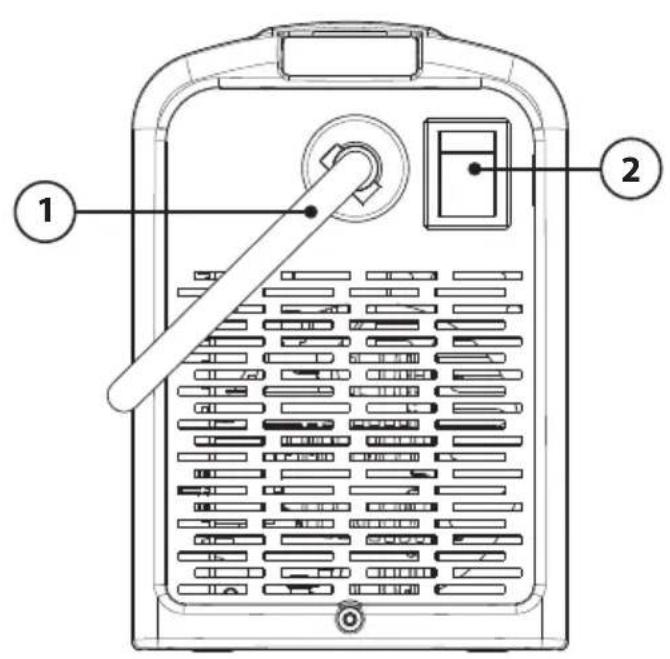
text_image
Technical diagram of a portable air conditioner unit with labeled parts 1 and 2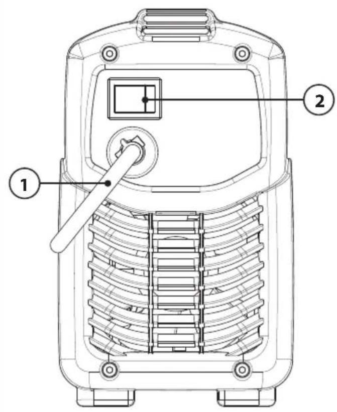
text_image
Technical diagram of a mobile phone with labeled parts including a control knob and numbered components.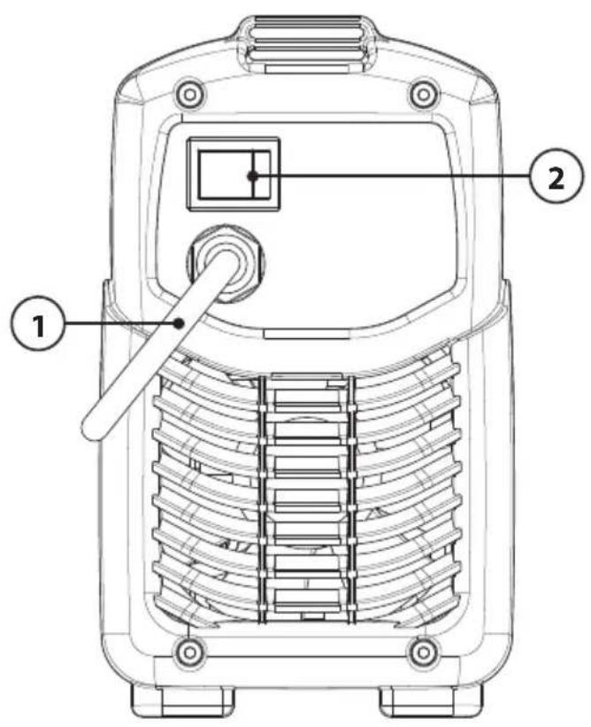
text_image
Technical diagram of a mobile phone rear panel with labeled components 1 and 2FIG. E
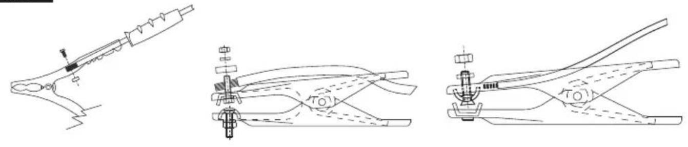
FIG. F
natural_image
Two-step diagram showing a welding torch being welded, with arrows indicating rotational motion (no text or symbols present)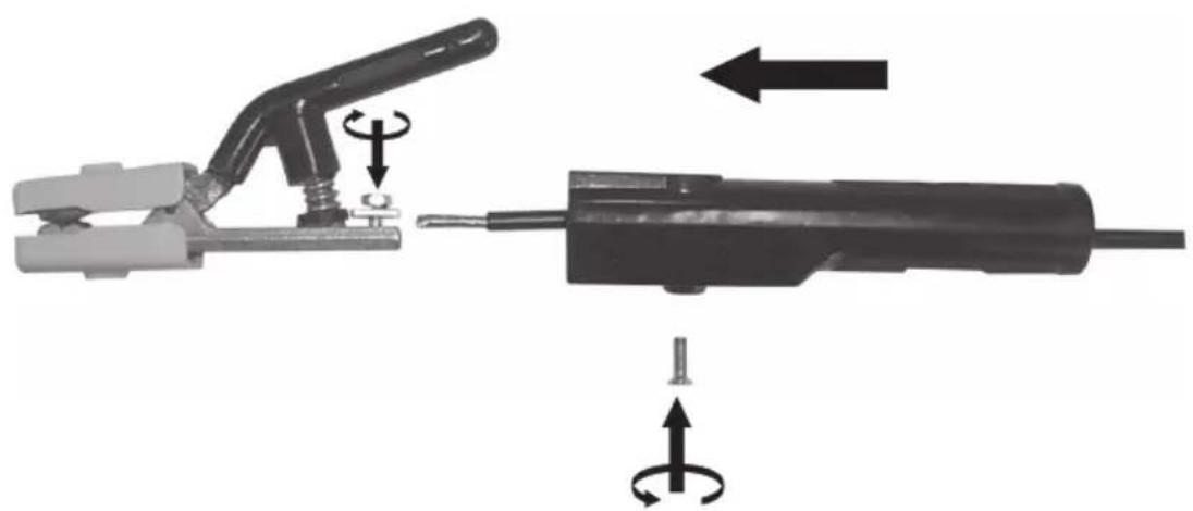
natural_image
Diagram showing two types of welding tools: a clamp and a tool, with rotational arrows indicating movement or force (no text or symbols present)FIG. G
text_image
D = S D S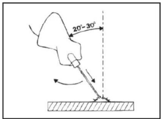
text_image
20°-30°FIG.H
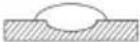 |  |  |  |
| (EN) ADVANCEMENT TOO SLOW(IT) AVANZAMENTO TROPPO LENTO(FR) AVANCEMENT TROP FAIBLE(ES) LASSNELHEID TE LAAG(DE) ZU LANGASAMES ARBEITEN(RU) МЕДЛЕННОЕ ПЕРЕМЕЩЕ НИЕ ЭЛЕКТРОДА(PT) AVANCE DEMASIADO VELOZ(EL) ПОАТ АРГО ПРОХОРГИМА(NL) AVANÇO MUITO LENTO(HU) AZ ELOTOLÁS TÜLSÁGOSAN LASSÚ(RO) AVANSARE PREA LENTA(SV) FÖR LÄNGSAM FLYTTNING(DA) GÄR FOR LANGSOMT FREMAD(NO) FOR SAKTE FREMDRIFT(FI) EDISTYS LIIAN HIDAS(CS) PRÍLİŠ POMALÝ POSUV(SK) PRÍLİŠ POMALÝ POSUV(SL) PREPOCASNO NAPREDOVANJE(HR-SR) PRESPORO NAPREDOVANJE(LT) PER LETAS JUDEJIMAS(ET) LIIGA AEGLANE EDASIMINEK(LV) KUSTIBA UZ PRIEKŠU IR PARAK LENA(BG) ПРЕКАЛЕНО БАВНО ПРЕДВИЖВАНЕ НА ЕЛЕКТРОДА(PL) POSUW ZBYT WOLNY(AR) التقدم بطّل للغaaية | (EN) ARC TOO SHORT(IT) ARCO TROPPO CORTO(FR) ARC TROP COURT(ES) LICHTBOOG TE KORT(DE) ZU KURZER BOGEN(RU) СЛИШКОМ КОРОТКАЯ ДУТА(PT) ARCO DEMASIADO CORTO(EL) ПОАТ КОНТО ТОЭО(NL) ARCO MUITO CURTO(HU) AZ İV TÜLSÁGOSAN RÖVID(RO) ARC PREA SCURT(SV) BÄGEN ÄR FÖR KORT(DA) LYSBUEN ER FOR KORT(NO) FOR KORT BUE(FI) VALOKAARI LIJAN LYHYT(CS) PRÍLİŠ KRÁTKÝ OBLOUK(SK) PRÍLİŠ KRÁTKY OBLÜK(SL) PREKRATEK OBLOK(HR-SR) PREKRATAK LUK(LT) PER TRUMPAS LANKAS(ET) LIIGA LÜHIKE KAAR(LV) LOKS IR PARAK ISS(BG) МНОГО КЪСА ДЪГА(PL) LUK ZBYT KRÖTKI(AR) القوس قصر للغaaية | (EN) CURRENT TOO LOW(IT) CORRENTE TROPPO BASSA(FR) COURANT TROP FAIBLE(ES) LASSTROOM TE LAAG(DE) ZU GERINGER STROM(RU) СЛИШКОМ СЛАБЫЙ TOK СВАРКИ(PT) CORRIENTE DEMASIADO BAJA(EL) ОПОАТ ХАМНАО РЕУМА(NL) CORRENTE MUITO BAIXA(HU) AZ ÁRAM ERTÉKE TÜLSÁGOSAN(RO) CURRENT CU INTENSITATE PREA SCÂZUTÃ(SV) FÖR LITE STRÖMALACSONY(DA) FOR LILLE STRÖMSTYRKE(NO) FOR LAV STRÖM(FI) VIRT A LIAN ALHAINEN(CS) PRÍLİŠ NÍZKÝ PROUD(SK) PRÍLİŠ NÍZKY PRŮD(SL) PREŠIBEK ELEKTRIČNI TOK(HR-SR) PRESLABA STRUJA(LT) PER SILPNA SROVE(ET) LIIGA MADAL VOOL(LV) STRÂVA IR PÂRÂK VÂJA(BG) МНОГО НИСЬК TOK(PL) PRÅD ZBYT NISKI(AR) التيار منخفض جداً | |
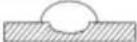
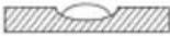 | 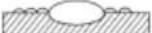 |  | (EN) CURRENT CORRECT(IT) CORDONE CORRETTO(FR) CORDON CORRECT(ES) CORDON CORRECTO(DE) RICHTIG(RU) НОРМАЛЬНЫЙ ШОВ(PT) CORRENTE CORRECTA(EL) ΣΩΣΤΟ ΚΟΡΔΟΝΙ(NL) JUISTE LASSTROOM(HU) A ZÁRÓVONAL PONTOS(RO) CORDON DE SUDURÃ CORECT(SV) RÄTT STRÖM(DA) KORREKT STRÖMSTYRKE(NO) RIKTIG STRÖM(FI) VIRT A OIKEA(CS) SPRÁVNY ŠVAR(SK) SPRÁVNY ZVAR(SL) PRAVILEN ZVAR(HR-SR) ISPRAVLJENI KABEL(LT) TAISYKLINGA SIÜLÉ(ET) KORREKTNE NŐÖR(LV) PAREIZA ŠUVE(BG) ПРАВИЛЕН ШЕВ(PL) PRAWIDIOWY ŚCIEG(AR) حبل صحیح |
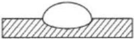
| (EN) ADVANCEMENT TOO FAST(IT) AVANZAMENTO TROPPO VELOCE(FR) AVANCEMENT EXCESSIF(ES) LASSNELHEID TE HOOG(DE) ZU SCHNELLES ARBEITEN(RU) БЫСТРОЕ ПЕРЕМЕЩЕНИЕ ЭЛЕКТРОДА(PT) AVANCE DEMASIADO LENTO(EL) ПОАТ ГРНГОРО ПРОХОРГИМА(NL) AVANÇO MUITO RAPIDO(HU) AZ ELÔTOLÁS TÜLSÁGOSAN GYORS(RO) AVANSARE PREA RAPIDÃ(SV) FÖR SNABB FLYTTNING(DA) GÄR FOR HURTIGT FREMAD(NO) FOR RASK FREMDRIFT(FI) EDISTYS LIJAN NOPEA(CS) PRÍLİŠ RYCHLÝ POSUV(SK) PRÍLİŠ RYCHLY POSUV(SL) PREHITRO NAPREDOVANJE(HR-SR) PREBRZO NAPREDOVANJE(LT) PER GREITAS JUDEJIMAS(ET) LIIGA KIIRE EDASIMINEK(LV) KUSTÍBA UZ PRIEKŠU IR PÂRÂK ÂTRA(BG) ПРЕКАЛЕНО БЪЗО ПРЕДВИЖВАНЕ НА ЕЛЕКТРОДА(PL) POSUW ZBYT SZYBKI(AR) التقدم سريع للغaaية | (EN) ARC TOO LONG(IT) ARCO TROPPO LUNGO(FR) ARC TROP LONG(E5) ARCO DEMASIADO LARGO(DE) ZU LANGER BOGEN(RU) СЛИШКОМ ДЛИННАЯ ДУГА(PT) ARCO MUITO LONGO(EL) ПОАТ МАКРÝ ТОЭО(NL) LICHTBOOG TE LANG(HU) AZ İV TÜLSÁGOSAN HOSSZÚ(RO) ARC PREA LUNG(SV) BÄGEN ÄR FÖR LÄNG(DA) LYSBUEN ER FOR LANG(NO) FOR LANG BUE(FI) VALOKAARI LIJAN PITKÃ(CS) PRÍLİŠ DLOUHY OBLOUK(SK) PRÍLİŠ DLHY OBLUK(SL) PREDOLG OBLOK(HR-SR) PREDUGI LUK(LT) PER ILGAS LANKAS(ET) LIIGA PIKK KAAR(LV) LOKS IR PÂRÂK GARŠ(BG) ПРЕКАЛЕНО ДЪЛГА ДЪГА(PL) LUK ZBYT DŁUGI(AR) القوس طويل للغaaية | (EN) CURRENT TOO HIGH(IT) CORRENTE TROPPO ALTA(FR) COURANT TROP ELEVE(ES) SPANNING TE HOOG(DE) ZU VIEL STROM(RU) СЛИШКОМ БОЛЬШОЙ TOK СВАРКИ(PT) CORRIENTE DEMASIADO ALTA(EL) ПОАТ YHAAO PETMA(NL) CORRENTE MUITO ALTA(HU) AZ ÁRAM ÉRTÉKE TÜLSÁGOSAN MAGAS(RO) CURRENT CU INTENSITATE PREA RIDICATÃ(SV) FÖR MYCKET STRÖM(DA) FOR STOR STRÖMSTYRKE(NO) FOR HÖY STRÖM(FI) VIRT A LIAN VOIMAKAS(CS) PRÍLİŠ VYSOKÝ PROUD(SK) PRÍLİŠ VYSOKÝ PRŮD(SL) PREMOĆAN ELEKTRIČNI TOK(HR-SR) PREJAKA STRUJA(LT) PER STIPRI SROVE(ET) LIIGA TUGEV VOOL(LV) STRÂVA IR PÂRÂK STIPRA(BG) МНОГО ВИСОК TOK(PL) PRÅD ZBYT WYSOKI(AR) التيار مرتفع جداً |
FIG. I FIG
natural_image
3D illustration of a person performing a physical maneuver with a curved pipe and distance label 'd' (no text or symbols beyond the label)
natural_image
Cross-sectional diagram of a mechanical or electrical component with internal channels and flow arrows (no text or symbols)TAB.1


WELDING MACHINE TECHNICAL DATA - DATI TECNICI SALDATRICE -
natural_image
Line drawing of a portable electronic device with ventilation slots and buttons (no text or symbols) |  |  |  |  | |||
| I_2 max | 115V 230 | V 115V 230V mm | 2 | kg | dB(A) | ||
| 80A - T10A - 16A 6 3.7 | <85 | ||||||
| 130A - T16A - 16A 10 2.8 | <85 | ||||||
| 150A - T16A - 16A 10 2.8 | <85 | ||||||
| 170A - T16A - 16A 10 2.9 | <85 | ||||||
natural_image
Line drawing of a portable electronic device with control panel and buttons (no text or symbols)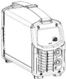
natural_image
Line drawing of a portable electronic device with front panel and control buttons (no text or symbols)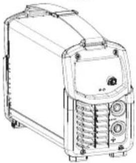
natural_image
Line drawing of a portable electronic device with control panel and buttons (no text or symbols)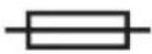 |  | 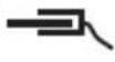 |  |  | |||
| I_2 max | 115V 230 | V 115V 2 | 30V mm | 2 | kg | dB(A) | |
| 80A - T10A - 16A 6 3.4 | <85 | ||||||
| 130A - T16A - 16A 10 2.7 | <85 | ||||||
| 140A - T16A - 16A 10 3.7 | <85 | ||||||
| 150A - T16A - 16A 10 2.8 | <85 | ||||||
| 160A - T20A - 32A 16 5 | <85 | ||||||
| 170A - T16A - 16A 10 2.9 | <85 | ||||||
| 200A - T25A - 32A 25 6 | <85 | ||||||
TAB.2


ELECTRODE HOLDER TECHNICAL DATA ACCORDING TO EN 60974-11 - DATI TECNICI PINZA PORTAELETTRODO IN ACCORDO ALLA EN 60974-11 -
The manufacturer guarantees proper operation of the machines and undertakes to replace free of charge any parts should they be damaged due to poor quality of materials or manufacturing defects within 12 months of the date of commissioning of the machine, when proven by certification. Returned machines, also under guarantee, should be dispatched CARRIAGE PAID and will be returned CARRIAGE FORWARD. This with the exception of, as decreed, machines considered as consumer goods according to European directive 1999/44/EC, only when sold in member states of the EU. The guarantee certificate is only valid when accompanied by an official receipt or delivery note. Problems arising from improper use, tampering or negligence are excluded from the guarantee. Furthermore, the manufacturer declines any liability for all direct or indirect damages.