Maxima 230 - Welding machine Telwin - Free user manual and instructions
Find the device manual for free Maxima 230 Telwin in PDF.
| Product type | Multi-process welding machine MIG/MAG, TIG, MMA |
| Brand | Telwin |
| Model | Maxima 230 |
| Power supply | Single-phase 230 V ±15%, 50/60 Hz |
| Welding current (MIG/MAG) | Adjustment range: see rating plate (e.g., 30-230 A) |
| Duty cycle (at 40°C) | See rating plate (e.g., 60% at 200 A) |
| Welding types | MIG/MAG (synergic), TIG (Lift Arc), MMA (covered electrode) |
| Synergic functions | Automatic programming of wire speed and current based on thickness |
| Available adjustments | Thickness (power), bead shape (arc length), arc force (MMA) |
| Integrated protections | Thermostatic, torch/ground short circuit, under/overvoltage |
| Included accessories | MIG torch, return cable with ground clamp |
| Optional accessories | Argon cylinder adapter, cart, auto-darkening mask, TIG/MMA kits |
| Recommended MIG wire diameters | Steel: 0.6-1.0 mm; Stainless: 0.8 mm; Aluminum: 0.8-1.0 mm |
| MIG/MAG shielding gas | CO₂ or Ar/CO₂ mixtures (8-14 l/min) |
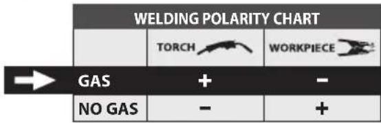
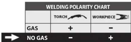
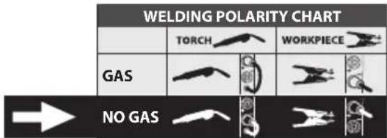
| Polarity | Reversible for FLUX welding (without gas): torch on negative terminal |
| Routine maintenance | Clean wire guide conduit with compressed air, check nozzle and contact tip, clean interior dust |
| User safety | Wear gloves, mask with filter, flame-resistant clothing mandatory; avoid contact with welding circuit |
| Protection classes | Class I (grounding mandatory) |
| Operating environment | Professional industrial (class A) |
| Approximate weight | Approximately 25-35 kg depending on version (not exactly specified) |
Frequently Asked Questions - Maxima 230 Telwin
User questions about Maxima 230 Telwin
0 question about this device. Answer the ones you know or ask your own.
Ask a new question about this device
Download the instructions for your Welding machine in PDF format for free! Find your manual Maxima 230 - Telwin and take your electronic device back in hand. On this page are published all the documents necessary for the use of your device. Maxima 230 by Telwin.
USER MANUAL Maxima 230 Telwin
CONTINUOUS WIRE WELDING MACHINE FOR MIG-MAG ARC AND FLUX, TIG, MMA WELDING FOR PROFESSIONAL AND INDUSTRIAL USE.
NB: The following text uses the term "Welding machine" and "Multiprocess Welding Machine" for models prepared for MIG-MAG AND FLUX, TIG, MMA welding.
1. GENERAL SAFETY CONSIDERATIONS FOR ARC WELDING
The operator should be properly trained to use the welding machine safely and should be informed about the risks related to arc welding procedures, the associated protection measures and emergency procedures.
(Please refer to the applicable standard "EN 60974-9: Arc welding equipment. Part 9: Installation and Use).

- Avoid direct contact with the welding circuit: the no-load voltage supplied by the welding machine can be dangerous under certain circumstances.
- When the welding cables are being connected or checks and repairs are carried out the welding machine should be switched off and disconnected from the power supply outlet.
- Switch off the welding machine and disconnect it from the power supply outlet before replacing consumable torch parts.
- Make the electrical connections and installation according to the safety rules and legislation in force.
- The welding machine should be connected only and exclusively to a power source with the neutral lead connected to earth.
- Make sure that the power supply plug is correctly connected to the earth protection outlet.
- Do not use the welding machine in damp or wet places and do not weld in the rain.
- Do not use cables with worn insulation or loose connections.
- Do not weld on containers or piping that contains or has contained flammable liquid or gaseous products.
- Do not operate on materials cleaned with chlorinated solvents or near such substances.
- Do not weld on containers under pressure.
- Remove all flammable materials (e.g. wood, paper, rags etc.) from the working area.
- Provide adequate ventilation or facilities for the removal of welding fumes near the arc; a systematic approach is needed in evaluating the exposure limits for the welding fumes, which will depend on their composition, concentration and the length of exposure itself.
- Keep the gas bottle (if used) away from heat sources, including direct sunlight.

- Use electric insulation that is suitable for the torch, the workpiece and any metal parts that may be placed on the ground and nearby (accessible).
This can normally be done by wearing gloves, footwear, head protection and clothing that are suitable for the purpose and by using insulating boards or mats. - Always protect your eyes with the relative filters, which must comply with UNI EN 169 or UNI EN 379, mounted on masks or use helmets that comply with UNI EN 175.
Use the relative fire-resistant clothing (compliant with UNI EN 11611) and welding gloves (compliant with UNI EN 12477) without exposing the skin to the ultraviolet and infrared rays produced by the arc; the protection must extend to other people who are near the arc by way of screens or non-reflective sheets. - Noise: If the daily personal noise exposure (LEPd) is equal to or higher
than 85 dB(A) because of particularly intensive welding operations, suitable personal protective means must be used (Tab. 1).
text_image
EMF SAFE- The flow of the welding current generates electromagnetic fields (EMF) around the welding circuit.
Electromagnetic fields can interfere with certain medical equipment (e.g. Pace-makers, respiratory equipment, metallic prostheses etc.).
Adequate protective measures must be adopted for persons with these types of medical apparatus. For example, they must be forbidden access to the area in which welding machines are in operation.
This welding machine conforms to technical product standards for exclusive use in an industrial environment for professional purposes. It does not assure compliance with the basic limits relative to human exposure to electromagnetic fields in the domestic environment.
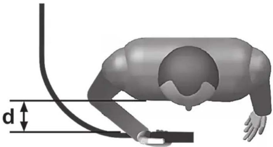
The operator must adopt the following procedures in order to reduce exposure to electromagnetic fields:
- Fasten the two welding cables as close together as possible.
- Keep head and trunk as far away as possible from the welding circuit.
- Never wind welding cables around the body.
- Avoid welding with the body within the welding circuit. Keep both cables on the same side of the body.
- Connect the welding current return cable to the piece being welded, as close as possible to the welding joint.
- Do not weld while close to, sitting on or leaning against the welding machine (keep at least 50 cm away from it).
- Do not leave objects in ferromagnetic material in proximity of the welding circuit.
- Minimum distance d=20 cm (Fig. G).

- Class A equipment:
This welding machine conforms to technical product standards for exclusive use in an industrial environment and for professional purposes. It does not assure compliance with electromagnetic compatibility in domestic dwellings and in premises directly connected to a low-voltage power supply system feeding buildings for domestic use.

- WELDING OPERATIONS:
- In environments with increased riskof electric shock;
- In confined spaces;
- In the presence of flammable or explosive materials; MUST BE evaluated in advance by an "Expert supervisor" and must always be carried out in the presence of other people trained to intervene in emergencies.
All protective technical measures MUST be taken as provided in 7.10; A.8; A.10 of the applicable standard EN 60974-9: Arc welding equipment. Part 9: Installation and Use".
- Welding MUST NOT be allowed if the welding machine or wire feeder is supported by the operator (e.g. using belts).
- The operator MUST NOT BE ALLOWED to weld in raised positions unless safety platforms are used.
- VOLTAGE BETWEEN ELECTRODE HOLDERS OR TORCHES: working with more than one welding machine on a single piece or on pieces that are connected electrically may generate a dangerous accumulation of no-load voltage between two different electrode holders or torches, the value of which may reach double the allowed limit.
An expert coordinator must be designated to measuring the apparatus to determine if any risks subsist and suitable protection measures can be adopted, as foreseen by section 7.9 of the applicable standard "EN 60974-9: Arc welding equipment. Part 9: Installation and Use".
- OVERTURNING: position the welding machine on a horizontal surface that is able to support the weight: otherwise (e.g. inclined or uneven floors etc.) there is danger of overturning.
- IMPROPER USE: it is hazardous to use the welding machine for any work other than that for which it was designed (e.g. de-icing mains water pipes).
- MOVING THE WELDING MACHINE: Always secure the gas bottle, taking suitable precautions so that it cannot fall accidentally (if used).
- Do not use the handle to hang the welding machine.

The safety guards and moving parts of the covering of the welding machine and of the wire feeder should be in their proper positions before connecting the welding machine to the power supply.

WARNING! Any manual operation carried out on the moving parts of the wire feeder, for example:
- Replacing rollers and/or the wire guide;
- Inserting wire in the rollers;
- Loading the wire reel;
- Cleaning the rollers, the gears and the area underneath them;
- Lubricating the gears.
SHOULD BE CARRIED OUT WITH THE WELDING MACHINE SWITCHED OFF AND DISCONNECTED FROM THE POWER SUPPLY OUTLET.
2. INTRODUCTION AND GENERAL DESCRIPTION
This welding machine is a source of current for arc welding, made specifically for MAG welding carbon steel or weak alloys with CO_2 protective gas or Argon/CO _2 mixes, using full or core electrode wires.
It is also ideal for MIG welding stainless steel with Argon gas containing +1-2% oxygen and aluminium and CuSi (brazing) with Argon gas, using electrode wires that are suitable for the workpiece to be welded.
Suitable core wires can also be used without Flux protection gas, adapting torch polarity according to the indications of the wire producer.
SYNERGIC operation ensures fast and easy welding parameter setting, always guaranteeing high arc control and welding quality.
It is particularly suitable for light metalwork fabrication and in body shops, for welding galvanized plates, high stress stainless steel and aluminium.
MULTIPROCESS VERSION:
The welding machine can be used for TIG welding in direct current (DC), with arc striking upon contact (LIFT ARC mode). It welds all types of steel (carbon, low- and high-alloy) and heavy metals (copper, nickel, titanium and their alloys) with a gas shield of pure (99.9%) Ar or, for special uses, with an Argon/Helium mix. It can also be used for MMA electrode welding in direct current (DC) using coated electrodes (rutile, acid, basic).
MAIN CHARACTERISTICS
MIG-MAG
- Synergic (automatic) operation;
- Burn-back time based on wire speed;
- Thermostatic safeguard;
- Protection against accidental short-circuits caused by contact between torch and earth;
- Protection against irregular power supplies (power supply voltage too high or too low);
- Polarity reversal (Flux Welding) (where applicable);
TIG (multiprocess version only)
- Start LIFT;
MMA (multiprocess version only)
- Hot start and anti-stick devices preset;
- Arc-force adjustment
- Indication of recommended electrode diameter based on welding current;
STANDARD ACCESSORIES
torch;
- return cable complete with earth clamp;
OPTIONAL ACCESSORIES
- Argon bottle adapter;
- Trolley (where applicable);
- Self darkening helmet;
- MIG/MAG welding kit;
- MMA welding kit;
- TIG welding kit.
3. TECHNICAL DATA
DATA PLATE
The most important data regarding use and performance of the welding machine are summarised on the rating plate and have the following meaning:
Fig. A
1- EUROPEAN standard of reference, for safety and construction of arc welding machines.
2- Symbol for internal structure of the welding machine.
3- Symbol for welding procedure provided.
4- Symbol S: indicates that welding operations may be carried out in environments with heightened risk of electric shock (e.g. very close to large metallic volumes).
5- Symbol for power supply line:
1\~: single phase alternating voltage;
3\~: 3-phase alternating voltage.
6- Protection rating of the covering.
7- Technical specifications for power supply line:
- U _1 : Alternating voltage and power supply frequency of welding machine (allowed limit ±10%).
- I : Maximum current absorbed by the line.
- I : effective current supplied.
8- Performance of the welding circuit:
- U : maximum no-load voltage (open welding circuit).
- I 2/U2 : current and corresponding normalised voltage that the welding machine can supply during welding.
- X : Duty cycle: indicates the time for which the welding machine can supply the corresponding current (same column). It is expressed as %, based on a 10 min. cycle (e.g. 60% = 6 minutes working, 4 minutes pause, and so on).
If the usage factors (on the plate, referring to a 40^ C environment) are exceeded, the thermal safeguard will trigger (the welding machine will remain in standby until its temperature returns within the allowed limits).
- A/V-A/V : shows the range of adjustment for the welding current (minimum maximum) at the corresponding arc voltage.
9- Manufacturer's serial number for welding machine identification (indispensable for technical assistance, requesting spare parts, discovering product origin).
10- : Size of delayed action fuses to be used to protect the power line.
11- Symbols referring to safety regulations, whose meaning is given in chapter 1 "General safety considerations for arc welding".
Note: The data plate shown above is an example to give the meaning of the symbols and numbers; the exact values of technical data for the welding machine in your possession must be checked directly on the data plate of the welding machine itself.
OTHER TECHNICAL DATA:
- WELDING MACHINE: see table 1 (TAB. 1)
- MIG TORCH: see table 2 (TAB. 2)
- TIG TORCH: see table 3 (TAB. 3)
- ELECTRODE-HOLDER CLAMP: see table 4 (TAB. 4)
The weight is of the welding machine is outlined on table 1 (TAB. 1).
4. DESCRIPTION OF THE WELDING MACHINE
CONTROL, ADJUSTMENT AND CONNECTION DEVICES.
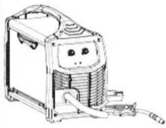
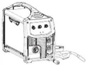
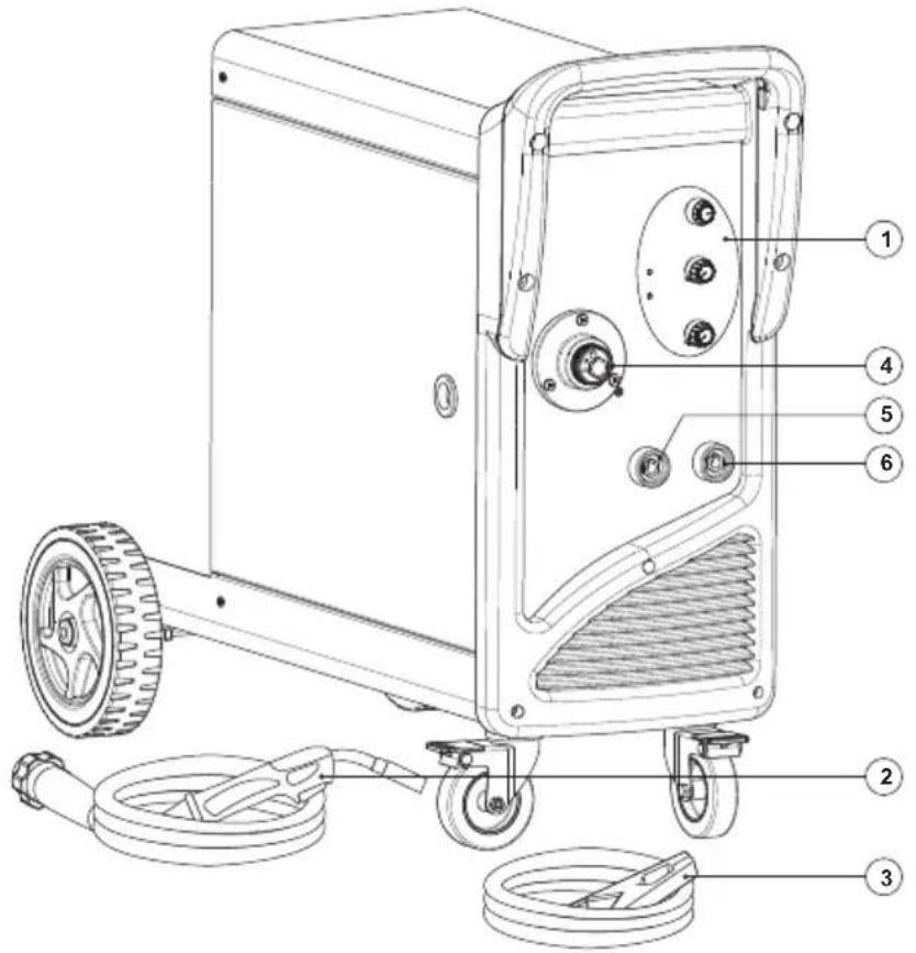
WELDING MACHINE (Fig. B1, B2)
At the front:
1- Control panel (see description).
2- Welding cable and torch.
3- Earth return cable and clamp.
4- Torch coupling.
5- Positive (+) fast coupling for connecting the welding cable.
6- Negative (-) fast coupling for connecting the welding cable.
7- Fast coupling plug connected to the torch coupling.
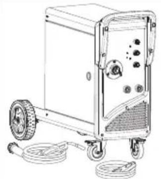
At the back:
8- Main ON/OFF switch.
9- Hose connector for protective gas.
10- Power cable.
On the reel area:
11- Positive clamp (+).
12- Negative clamp (-).
NB: Polarity inversion for FLUX welding (no gas).
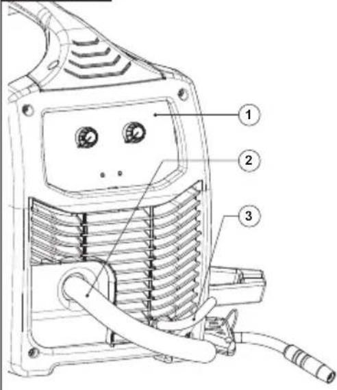
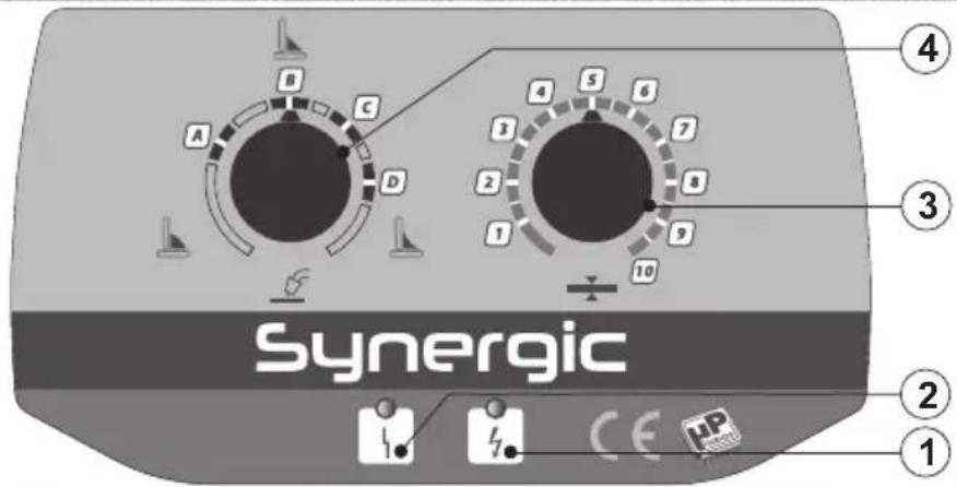
WELDING MACHINE CONTROL PANEL (Fig. C)
1- Mains voltage present signalling led.
2- Alarm signalling led (activation of safety thermostat, short circuit between torch and earth cable, over/undervoltage).

MIG-MAG MODE:
Material thickness adjustment (welding power).
ultiprocess version only):
Adjustment of welding current indicating the recommended electrode diameter.

TIG MODE (multiprocess version only):
Adjustment of welding current.
4- MIG-MAG MODE:

: Adjustment of the welding seam (arc length);

: default setting.

: lower arc voltage.

: upper arc voltage.


MMA MODE (multiprocess version only):
Adjustment of arc force (0-100%).
TIG MODE (multiprocess version only):
not enabled.
5- MIG-MAG, TIG or MMA welding process selector (multiprocess version only).
5. INSTALLATION

ALL INSTALLATION OPERATIONS AND
ELECTRICAL CONNECTIONS MUST ALWAYS BE CARRIED OUT WITH THE WELDING MACHINE SWITCHED OFF AND DISCONNECTED FROM THE POWER SUPPLY.
THE ELECTRIC CONNECTIONS MUST ONLY BE CARRIED OUT BY EXPERT OR QUALIFIED TECHNICIANS.
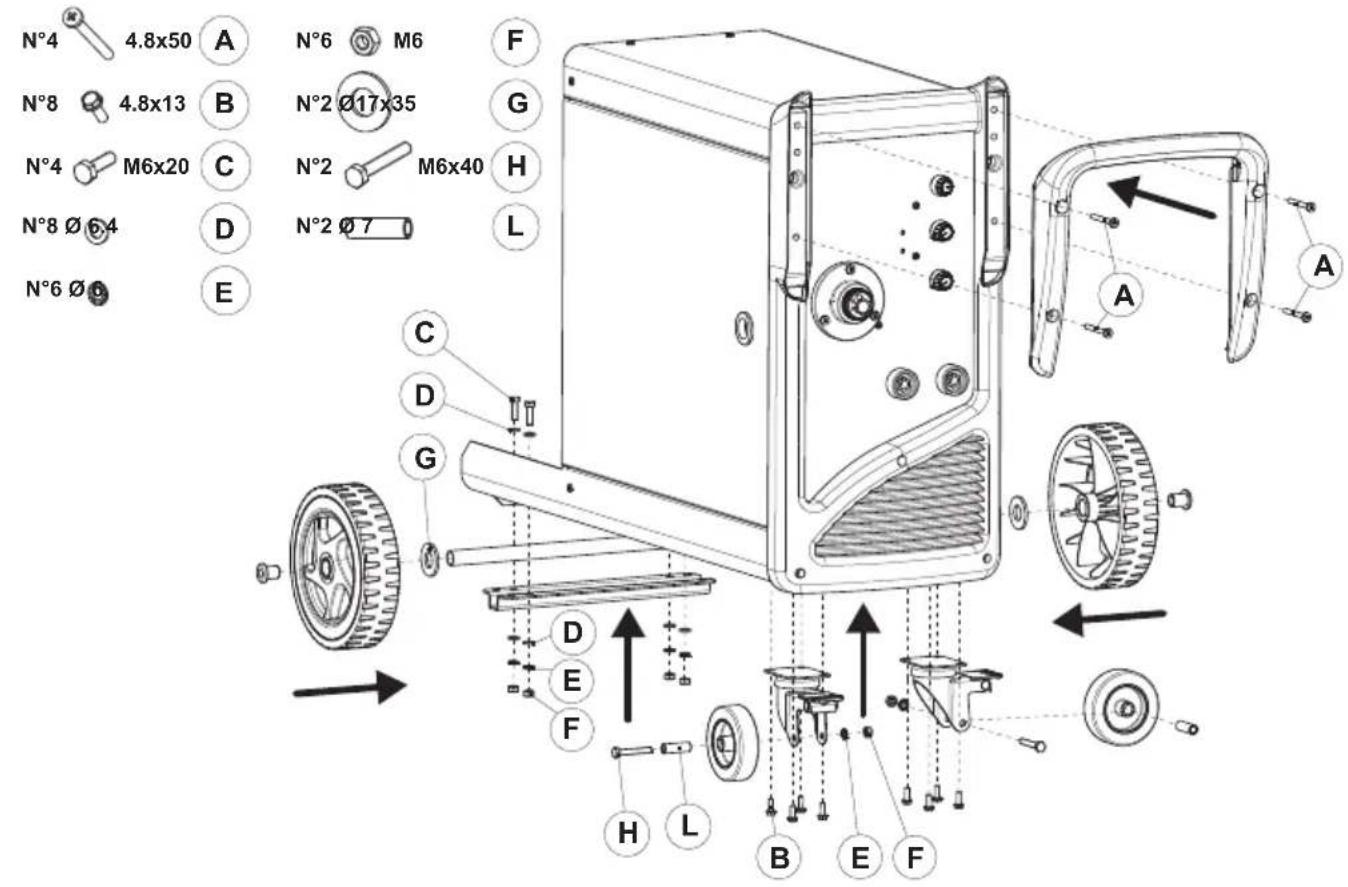
PREPARATION (180 A version)
Fig. D
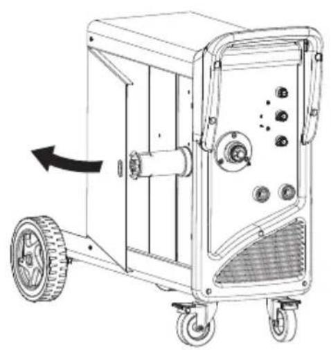
Unpack the welding machine, assemble the separate parts contained in the package.
Assembling the return cable-clamp
Fig. D1
Assembling the welding cable-electrode-holder clamp
Fig. D2
POSITIONING THE WELDING MACHINE
Choose the place where the welding machine is to be installed so that there are no obstructions to the cooling air inlets and outlets; at the same time make sure that conductive dust, corrosive vapours, humidity etc. cannot be drawn into the machine.
Leave at least 250 mm of free space all around the welding machine.

WARNING! Position the welding machine on a level surface with sufficient load-bearing capacity, so that it cannot be tipped over or shift dangerously.
CONNECTION TO THE MAIN POWER SUPPLY
- Before making any electrical connection, check the rating plate data on the welding machine to make sure they correspond to the voltage and frequency of the available power supply where the machine is to be installed.
- The welding machine must be connected only and exclusively to a power supply with the neutral conductor connected to earth.
- To guarantee protection against indirect contact use the following types of residual current devices:
- A type ( ∼ ) for single-phase machines.

- In order to satisfy the requirements of the EN 61000-3-11 (Flicker) standard we recommend connecting the welding machine to the interface points of the main power supply that have an impedance of less than Zmax = 0.24 ohm.
- The IEC/EN 61000-3-12 Standard does not apply to the welding machine.
If the welding machine is connected to an electrical grid, the installer or user must make sure that the machine can indeed be connected (if necessary, consult the company that manages the electrical grid).
Plug and outlet
Connect the power supply plug to a mains socket fitted with fuses or an automatic circuit-breaker; the corresponding earth terminal should be connected to the (yellow-green) earth conductor of the power supply. Table 1 (TAB. 1) shows the recommended delayed fuse sizes, in amps, for the main supply, which have been chosen according to the maximum rated current output from the welding machine, and to the nominal power supply voltage.

WARNING! Non-compliance with the above regulations renders the manufacturer's safety system (class I) inefficient, with resulting serious risks to people (e.g. electric shock) and things (e.g. fire).
WELDING CIRCUIT CONNECTIONS

WARNING! BEFORE CARRYING OUT THE FOLLOWING TIONS MAKE SURE THAT THE WELDING MACHINE IS D OFF AND DISCONNECTED FROM THE POWER SUPPLY.
Table 1 (TAB. 1) shows the recommended sizes of the welding cables (in mm ^2 ), according to the maximum current output from the welding machine.
Furthermore:
- Fully rotate the welding cable connectors in the fast coupling (if present), to guarantee perfect electrical contact; on the contrary, the connectors will overheat causing their rapid wear and loss of efficiency.
- Use welding cables that are as short as possible.
- Do not use metal structures that are not part of the workpiece, when replacing the welding current return cable; this can endanger safety and give unsatisfactory cleaning results.
WELDING CIRCUIT CONNECTIONS IN MIG-MAG MODE
Connecting to the gas bottle (if used)
- The gas bottle that can be positioned on the trolley supporting surface: max 30kg.
- Gas bottle can be loaded on welding machine bottle support platform: max 30kg (for 180A version only).
- Screw the pressure reducer(*) onto the gas bottle, inserting the appropriate adapter supplied as an accessory when Argon or an Argon/ CO₂ mixture is used.
- Connect the gas input hose to the reducer and tighten the clamp.
- Loosen the adjustment ring nut on the pressure reducing valve before opening the gas bottle valve.
(*) Accessory to be purchased separately if not supplied with the product.
Connecting the welding current return cable
Must be connected to the workpiece or to the metal bench on which it is positioned, keeping it as close as possible to the joint being done.
Torch
Prepare the torch when loading the wire for the first time, by dismantling the nozzle and the contact tip, to ease its exit.
Internal polarity change Fig. B1
- Open the reel area door.
- MIG/MAG welding (gas):
- Connect the torch cable to the red clamp (+) (Fig. B-11)
- Connect the clamp return cable to the negative fast coupling (-) (Fig. B-12).
- FLUX welding (no gas):
- Connect the torch cable to the black clamp (-) (Fig. B-12).
- Connect the clamp return cable to the positive fast coupling (+) (Fig. B-11).
- Close the reel area door.
External polarity change (multiprocess version only) Fig. B1
MIG/MAG welding (gas):
- Connect the torch cable to the torch coupling (Fig. B-4).
-
Connect the fast coupling plug (Fig. B-7) to the positive coupling plug (+) (Fig. B-5).
-
Connect the clamp return cable to the negative fast coupling (-) (Fig. B-6).
- FLUX welding (no gas):
- Connect the torch cable to the torch coupling (Fig. B-4).
- Connect the fast coupling plug (Fig. B-7) to the negative coupling (-) (Fig. B-6).
- Connect the clamp return cable to the positive fast coupling (+) (Fig. B-5).
WELDING CIRCUIT CONNECTIONS IN TIG MODE
Gas cylinder connection
- Screw the pressure reducer onto the cylinder gas valve, if necessary, inserting the specific reduction supplied as an accessory.
- Connect the input hose of the gas reducer and tighten with the supplied strip.
- Loosen the adjustment ring nut of the pressure reducer before opening the cylinder valve.
- Open the cylinder and adjust the quantity of gas (l/min) according to the illustrative use data, see table (TAB. 5); any adjustments in gas flow can be carried out during welding always using the pressure reducer ring nut. Check the tubing and fittings.

WARNING! Always close the gas cylinder valve at the end
of work.
Connecting the welding current return cable
- Connect the cable to the piece to be welded or the metal bench on which the workpiece is placed, as close as possible to the joint being worked. Connect this cable to the clamp with the symbol (+) (Fig. B-5).
Torch
- Insert the current cable in the specific fast clamp (-) (Fig. B-6). Connect the gas hose of the torch to the cylinder.
WELDING CIRCUIT CONNECTIONS IN MMA MODE
Almost all the coated electrodes should be connected to the positive pole (+) of the generator; an exception is the negative pole (-) for electrodes with acid coating.
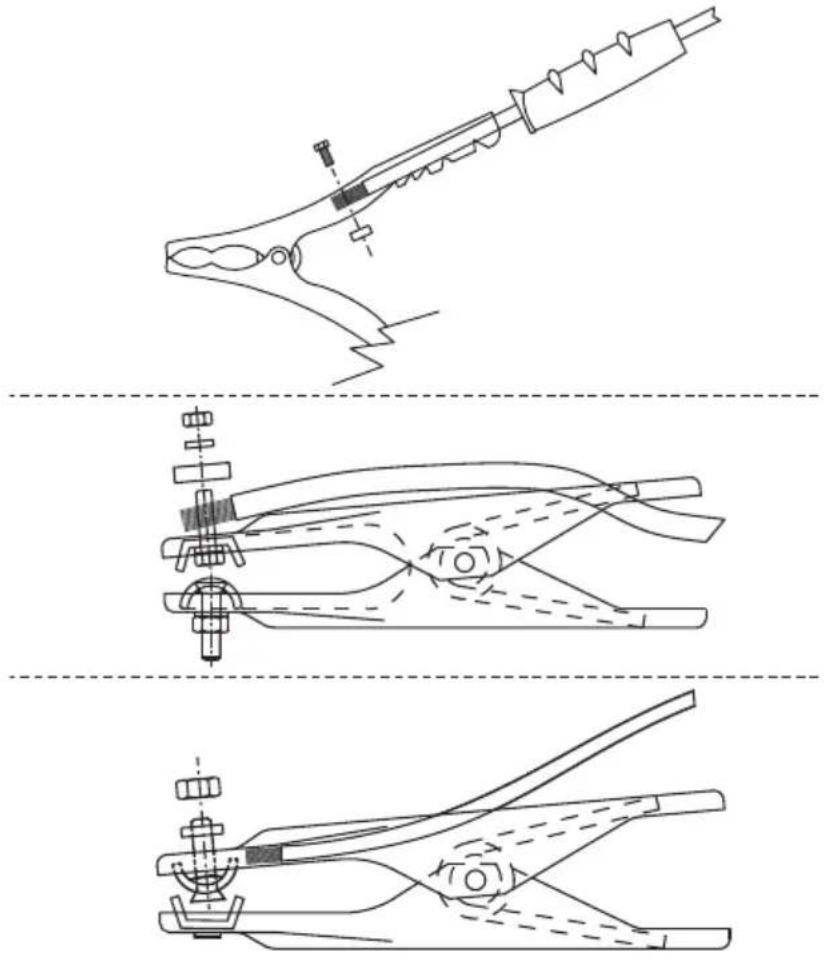
Connection of the electrode-holder clamp welding cable (Fig. D2)
Bring a special clamp on the clamp used to tighten the exposed part of the electrode. Connect this cable to the clamp with the symbol (+) (Fig. B-5).
Connecting the welding current return cable
Connect the cable to the piece to be welded or the metal bench on which the workpiece is placed, as close as possible to the joint being worked. Connect this cable to the clamp with the symbol (-) (Fig. B-6).
LOADING THE WIRE REEL (Fig. E)

WARNING! BEFORE STARTING THE OPERATIONS TO LOAD
THE WIRE MAKE SURE THE WELDING MACHINE IS SWITCHED OFF AND DISCONNECTED FROM THE MAIN POWER SUPPLY OUTLET.
MAKE SURE THAT THE WIRE FEEDER ROLLERS, THE WIRE GUIDE HOSE AND THE CONTACT TIP OF THE TORCH MATCH THE DIAMETER AND TYPE OF WIRE TO BE USED AND MAKE SURE THAT THESE ARE FITTED CORRECTLY. WHEN INSERTING AND THREADING THE WIRE DO NOT WEAR PROTECTIVE GLOVES.
- Open the reel compartment door.
- Position the wire reel on the spindle, holding the end of the wire upwards; make sure the tab for pulling the spindle is correctly seated in its hole (1a).
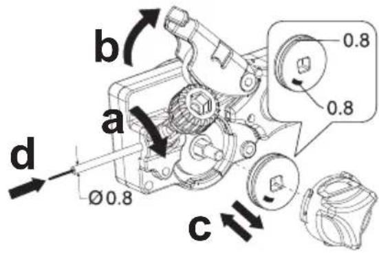
- Release the pressure counter-roller(s) and move them away from the lower roller(s) (2a-b);
- Make sure that the towing roller(s) is suited to the wire used (2c).
- Free the end of the wire and remove the distorted end with a clean cut and no burr; turn the reel anti-clockwise and thread the end of the wire into the wire-guide infeed, pushing it 50-100mm into the wire guide of the torch fitting (2d).
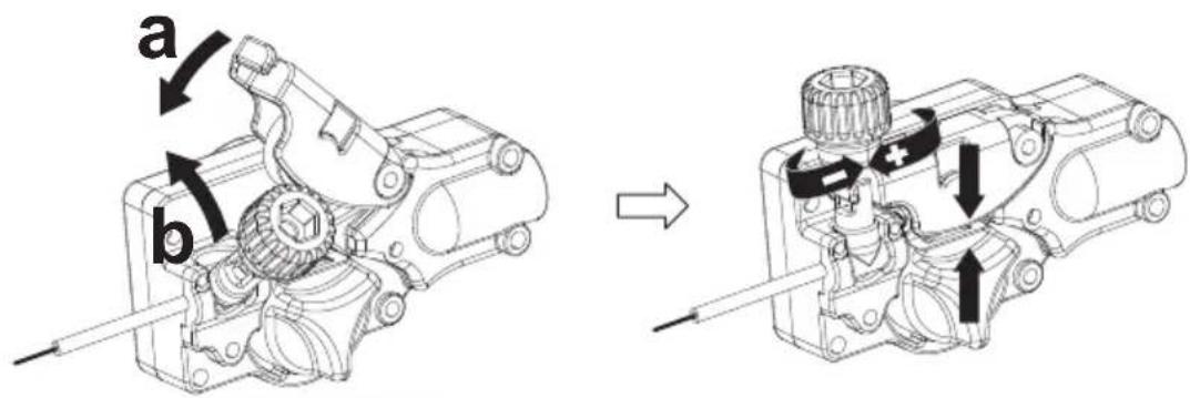
- Re-position the counter-roller(s), adjusting the pressure to an intermediate value, and make sure that the wire is correctly positioned in the groove of the lower roller(s) (3)
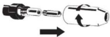
- Remove the nozzle and contact tip (4a).
- Insert the welding machine plug in the power supply outlet, switch on the welding machine, press the torch button and wait for the end of the
wire to pass through the whole of the wire guide hose and protrude by 10-15 cm from the front part of the torch, release the button.

WARNING! During these operations the wire is live and so mechanical stress; therefore if adequate precautions are in the wire could cause hazardous electric shock, injury and of electric arcs:
- Do not direct the mouthpiece of the torch towards parts of the body.
- Keep the torch away from the gas bottle.
- Re-fit the contact tip and the nozzle onto the torch (4b).
- Check that wire feed is regular; set the roller and spindle braking pressure to the minimum possible values making sure that the wire does not slide in the groove and when feed is halted the loops of wire are not loosened by excessive reel inertia.
- Cut the end of the wire so that 10-15 mm protrude from the nozzle.
- Close the reel compartment door.
6. WELDING: DESCRIPTION OF PROCEDURE
SHORT ARC
The wire melts and the bead detaches as a result of the subsequent short-circuits in the wire tip positioned in the weld pool (up to 200 times per second). The wire stick-out is normally between 5 and 12 mm.
Carbon steel and low-alloy steel
- Usable wire diameter: 0.6 - 0.8 mm (1.0 mm - 180 A version)
- Usable gas: CO or Ar/CO₂ mixes.
Stainless steel
- Usable wire diameter: 0.8 mm (1.0 mm - 180 A version)
- Usable gas: Ar/O 2 or Ar/CO 2 (1-2%) mixtures
Aluminium and CuSi
- Usable wire diameter: 0.8 - 1.0 mm
- Usable gas: Ar
Flux-core wire
- Usable wire diameter: 0.8 - 1.2 mm (140 A version)
0.8 - 0.9 mm (115 A version)
- Usable gas:
None
SHIELDING GAS
The shielding gas flow rate must be 8-14 l/min.
ADJUSTING THE WELDING BEAD
The bead shape is adjusted using the knob (Fig. C-4) which adjusts the arc length and thus determines the greater or lesser intake of the sealing temperature.
Referring to the table available in the machine (Fig. F), set the knob (Fig. C-4) depending on the material, wire and gas used. The points A, B, C, D represent good starting points for welding in different working conditions.

Convex shape: it means that there is a low thermal transfer,
therefore the welding, is "cold", with little penetration; rotate the knob clockwise to obtain a higher thermal transfer with the effect of a weld with higher fusion.

Concave shape: it means that there is a high thermal transfer,
therefore the welding is too "hot", with excessive penetration; turn the knob counterclockwise to obtain a lower melting.
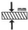
SETTING THICKNESS
The setting of the thickness is carried out by adjusting the knob (Fig. C-3). This knob regulates the welding power according to sheet thickness and affects simultaneously the wire feeder speed as well as the amount of current transferred to the filler wire.
Referring to the table provided in the machine (Fig. F), set the knob (Fig. C-3) depending on the material, wire, gas, and thickness that will be welded.
7. TIG DC WELDING: DESCRIPTION OF THE PROCEDURE (multiprocess version only)
GENERAL PRINCIPLES
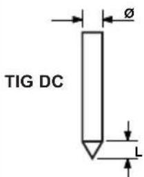
TIG DC welding is suitable for all types of low-alloy and high carbon steel, and heavy metals such as copper, nickel, titanium and their alloys (Fig. H). An electrode with 2% Cerium (grey band) is normally used for TIG DC welding with electrode at the (-) pole. The tungsten electrode must be axially sharpened using a grinding wheel, see Fig. I; make sure the tip is perfectly concentric to prevent arc deviation. The electrode must be ground along its length. This operation must be repeated periodically according to the use and wear state of the electrode, or
when the electrode itself has been accidentally contaminated, oxidised or used incorrectly. For the welding to be good, the exact diameter of the electrode must be used with the exact current, see table (TAB. 5). The electrode normally projects from the ceramic nozzle by 2-3 mm, but can reach 8 mm for welding edges.
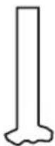
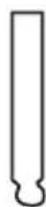
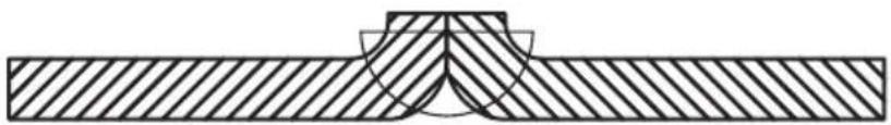
The weld is created by the edges that melt. Filler metal is not needed when welding suitably prepared thin material (up to about 1 mm) (Fig. L). A greater thickness requires rods made from the same material as the basic material and with a suitable diameter, with edges that have been suitably prepared (Fig. M). For welding to be successful, the pieces must be carefully cleaned and free from oxide, grease, oil, solvent, etc.
PROCEDURE (LIFT STRIKE)
- Adjust the welding current to the desired value using knob C-3; Adapt the current during welding to the real thermal load necessary.
- Make sure the gas is flowing correctly.
The arc ignites through contact, distancing the tungsten electrode from the workpiece. Igniting in this manner causes less electric-irradiated disturbances and reduces tungsten inclusions and electrode wear to a minimum.
- Place the tip of the electrode on the workpiece, pressing gently.
- Immediately lift the electrode by 2÷3 mm to obtain the arc strike. The welding machine initially supplies reduced current. After a few seconds, the set welding current is issued.
- Quickly lift the electrode from the workpiece to interrupt welding.
8. MMA WELDING: DESCRIPTION OF THE PROCEDURE (multiprocess version only)
GENERAL PRINCIPLES
- It is essential to follow the recommendations provided by the manufacturer on the electrode packaging which indicates the correct electrode polarity and relative rated current.
- Welding current is regulated to suit the diameter of the electrode being used and the type of soldering to be performed; an example of the currents used for the various electrode diameters can be seen below:
| ∅ Electrode (mm) | Welding current (A) | |
| Min. Max. | ||
| 1.6 25 50 | ||
| 2.0 40 80 | ||
| 2.5 60 110 | ||
| 3.2 80 150 | ||
- One can see that for the same diameter electrode, high levels of current will be used for flat welding, whilst lower current levels will be used for vertical or overhead welding.
- The mechanical characteristics of the welded joint are determined by the intensity of the selected current and also other welding parameters such as the length of the arc, the operating speed and position, the diameter and quality of the electrodes (to ensure correct conservation, use special packaging or containers to store and protect the electrodes against humidity).

WARNING:
Instability of the arc due to the composition of the electrode can occur, depending on the brand, type and thickness of the electrode coatings.
PROCEDURE
- Keeping the mask IN FRONT OF YOUR FACE, rub the tip of the electrode on the piece to be welded, moving as if striking a match; this is the most correct method for igniting the arc.
WARNING: DO NOT TAP the electrode against the workpiece, which could damage the coating and make arc striking difficult.
As soon as the arc has struck, try to keep the electrode at a distance from the workpiece that is equivalent to the diameter of the electrode being used, and keep this distance as constant as possible while welding; remember that the electrode angle while moving forward must be approx. 20-30 degrees. - At the end of the welding seam, take the electrode end slightly back as to the forward direction, above the crater to fill it, then quickly lift the electrode from the weld pool to switch off the arc (Aspects of the welding seam - Fig. N).
9. MAINTENANCE

- Do not put the torch or its cable on hot pieces; this would cause the insulating materials to melt, making the torch unusable after a very short time;
- Make regular checks on the gas pipe and connector seals;
- Every time the wire reel is changed, blow out the wire-guide hose using dry compressed air (max. 5 bar) to make sure it is not damaged;
- Before every use, check the wear and correct assembly of the parts at the end of the torch: nozzle, contact tip, gas diffuser.
Wire feeder
- Make frequent checks on the state of wear of the wire feeder rollers, regularly remove the metal dust deposited in the feeder area (rollers and wire-guide infeed and outfeed).
WARNING! BEFORE REMOVING THE WELDING MACHINE AND WORKING INSIDE THE MACHINE MAKE SURE THE G MACHINE IS SWITCHED OFF AND DISCONNECTED FROM N POWER SUPPLY OUTLET.
If checks are made inside the welding machine while it is live, this may cause serious electric shock due to direct contact with live parts and/or injury due to direct contact with moving parts.
- Inspect the welding machine regularly, with a frequency depending on use and the dustiness of the environment, and remove the dust deposited on the transformer, reactance and rectifier using a jet of dry compressed air (max. 10 bar).
- Do not direct the jet of compressed air on the electronic boards; these can be cleaned with a very soft brush or suitable solvents.
- At the same time make sure the electrical connections are tight and check the wiring for damage to the insulation.
- At the end of these operations re-assemble the panels of the welding machine and screw the fastening screws right down.
- Never, ever carry out welding operations while the welding machine is open.
- After having carried out maintenance or repairs, restore the connections and wiring as they were before, making sure they do not come into contact with moving parts or parts that can reach high temperatures. Tie all the wires as they were before, being careful to keep the high voltage connections of the primary transformer separate from the low voltage ones of the secondary transformer.
Use all the original washers and screws when closing the casing.
10. TROUBLESHOOTING
IN CASE OF UNSATISFACTORY FUNCTIONING, BEFORE SERVICING MACHINE OR REQUESTING ASSISTANCE, CARRY OUT THE FOLLOWING CHECK:
- Check that when general switch is ON the relative lamp is ON. If this is not the case then the problem is located on the mains (cables, plugs, outlets, fuses, etc.)
- Check that the yellow led (ie. thermal protection interruption- either over or undervoltage or short circuit) is not lit.
- Check that the nominal intermittance ratio is correct. In case there is a thermal protection interruption, wait for the machine to cool down, check that the fan is working properly.
- Check the mains voltage: if the value is too high or too low the welding machine will be stopped.
- Check that there is no short-circuit at the output of the machine: if this is the case eliminate the incovenience.
- Check that all connections of the welding circuit are correct, particularly that the work clamp is well attached to the workpiece, with no interfering material or surface-coverings (ie. Paint).
- Protective gas must be of appropriate type and quantity.
(IT)
MANUALE ISTRUZIONE
ATTENZIONE:
PRIMA DI UTILIZZARE LA SALDATRICE LEGGERE ATTENTAMENTE IL MANUALE DI ISTRUZIONE.
SALDATRICE A FILO CONTINUO PER LA SALDATURA AD ARCO MIG-MAG E FLUX, TIG, MMA PREVISTE PER USO PROFESSIONALE E INDUSTRIALE.
PROCEDIMENTO (INNESCO LIFT)
MANUEL D'INSTRUCTIONS
ATTENTION! AVANT TOUTE UTILISATION DU POSTE DE SOUDAGE, LIRE ATTENTIVEMENT LE MANUEL D'INSTRUCTIONS.
POSTE DE SOUDAGE À FIL CONTINU POUR LE SOUDAGE À L'ARC MIG-MAG ET FLUX, TIG, MMA PRÉVU POUR UNE UTILISATION PROFESSIONNELLE ET INDUSTRIELLE.
SHORT ARC (ARC COURT)
PROCÉDÉ (AMORÇAGE LIFT)
MANUAL DE INSTRUÇÕES

CUIDADO! ANTES DE UTILIZAR A MÁQUINA DE SOLDA LER CUIDADOSAMENTE O MANUAL DE INSTRUÇÕES!
APARELHO DE SOLDAR DE FIO CONTÍNUO PARA A SOLDADURA EM ARCO MIG-MAG E FLUX, TIG, MMA PREVISTAS PARA USO PROFISSIONAL E INDUSTRIAL.
SHORT ARC (ARCO CURTO)
MANUAL DE INSTRUCTIUNI
ATENTIE: CITIȚI CU ATENȚIE ACEST MANUAL DE INSTRUCTIUNI ÎNAINTE DE FOLOSIREA APARATULUI DE SUDURĂ!
APARAT DE SUDURĂ CU FIR CONTINUU PENTRU SUDURA CU ARC MIG-MAG ȘI FLUX, TIG, MMA PREVĂZUTE PENTRU UZ PROFESIONAL ȘI INDUSTRIAL.
VERSIUNEA MULTIPROCES:
SHORT ARC (ARC SCURT)
FUNKTIONSLÄGE MMA (bara version multiprocess):
FUNKTIONSLÄGE TIG (bara version multiprocess):
inte aktiverad.
EKSTRA FORHOLDSREGLER
SVEISEOPERASJONER:
- I miljöer med stor risiko for elektrisk støt;
- I avgrenset mijøer;
: standard innstilling.

ALMINDELIG VEDLIKEHOLD
ALMINDELIGE VEDLIKEHOLDSOPERASJONER KAN FULLF∅RES AV OPERAT∅REN.
Sveisebrenner
EKSTRAORDINÄRT VEDLIKEHOLD
ALT EKSTRAORDINÆRT VEDLIKEHOLD FÅR KUN UTF∅RES AV PERSONELL MED ERFARING ELLER KVALIFIKASJONER I ELEKTRISKE OG MEKANISKE OMRÅDER, I SAMSVAR MED DE TEKNISKE STANDARDENE IEC/EN 60974-4.

ADVARSEL: FJERN ALDRI DEKSLER ELLER UTF∅R ARBEID IHETEN DERSOM DEN IKKE ER FRAKOPLET STR∅MNETTET.
VOLITELNÉ PŘÍSLUŠENSTVÍ
2. UVOD IN SPLOŠNI OPIS
KEEVITUSSEADE (Joon. B1, B2)
Esiküljel:
KEEVITUSAHELA ÜHENDUSED REŽIIMIS MMA
KEEVITAJA VÕIB TEOSTADA NORMAALSEID HOOLDUSTÕID.
Põleti
PIESLĚGŠANA PIE TÍKLA
NADZWYCZAJNA KONSERWACJA
OPERACJE NADZWYCZAJNEJ KONSERWACJI MUSZĄ BYĆ WYKONYWANE WYŁĄCZNIE PRZEZ PERSONEL DOŚWIADCZONY LUB WYKWALIFIKOWANY W ZAKRESIE ELEKTRYCZNO-MECHANICZNYM, ZGODNIE Z NORMĄ TECHNICZNA IEC/EN 60974-4.

UWAGA! PRZED WYJĘCIEM PANELI SPAWARKI I DOSTANIEM
SIĘ DO JEJ WNĘTRZA NALEŻY UPEWNIĆ SIĘ, ŻE SPAWARKA ZOSTAŁA WYŁĄCZONA I ODŁĄCZYĆ ZASILANIE.
- airport airport airport airport airport airport airport airport airport airport airport airport airport airport airport airport airport airport airport airport airport airport airport airport airport airport airport airport airport airport airport airport airport airport airport airport airport airport airport airport airport airport airport airport airport airport airport airport airport airport airport airport airport airport airport airport airport airport airport airport airport airport airport airport airport airport airport airport airport airport airport airport airport airport airport airport airport airport airport airport airport airport airport airport airport airport airport airport airport airport airport airport airport airport airport airport airport airport airport airport Airport airport airport airport airport Airport airport Airport airport Airport Airport Airport Airport Airport Airport Airport Airport Airport Airport Airport Airport Airport Airport Airport Airport Airport Airport Airport Airport Airport Airport Airport Airport Airport Airport Airport Airport Airport Airport Airport Airport Airport Airport Airport Airport Airport Airport Airport Airport Airport Airport Airport Airport Airport Airport Airport Airport Airport Airport Airport Airport Airport Airport Airport Airport Airport Airport Airport Airport Airport Airport Airport Airport Airport Airport Airport Airport Airport Airport Airport Airport Airport Airport Airport Airport Airport Airport Airport Airport Airport Airport Airport Airport Airport Airport Airport Airport Airport Airport Airport Airport Airport Airport Airport Airport Airport Airport Airport Airport airports
text_image
FUSE T A 10 11TAB.1
WELDING MACHINE TECHNICAL DATA - DATI TECNICI SALDATRICE
| MODEL |  | (K8ZH) |  | [103W] |  |  |
| I_2 max (A) 230V 230V mm | 2 | kg m/min dB(A) | ||||
| 115 T16A | 16A 10 9.3 2 - | 14 <85 | ||||
| 140 T16A | 16A 16 9.9 2 - | 15 <85 | ||||
| 180 T16A | 16A 16 22 2 - | 16 <85 | ||||
MIG TORCH TECHNICAL DATA ACCORDING TO EN 60974-7 - DATI TECNICI TORCIA MIG IN ACCORDO ALLA EN 60974-7
| MODEL | VOLTAGE CLASS: 113V | ||||
| I_2 max (A) I | max (A) X (%) | [04/94] | [05/40] | ||
 | 115 | 115 35 Ar CO | _2/CO_2 | STEEL: 0.6 ÷ 1AL: 0.8 ÷ 1INOX: 0.8FLUX CORED: 0.8 ÷ 1.2 | |
| 90 35 NO GAS | |||||
| 140 | 140 35 Ar CO | _2/CO_2 | |||
| 115 35 NO GAS | |||||
 | 140180 | 150 60 Ar/CO | 2 | STEEL: 0.6 ÷ 1Al: 0.8 ÷ 1INOX: 0.8 | |
 | 180 60 CO | 2 | |||
TAB.3


TIG TORCH TECHNICAL DATA ACCORDING TO EN 60974-7 - DATI TECNICI TORCIA TIG IN ACCORDO ALLA EN 60974-7
| [V8KW] VOLTAGE CLASS: 113V | ||||
| I max (A) X | (%) | [40WTV] |  | COOLING |
| --- 100 | 35 | Argon 1 ÷ 1.6 Air / Gas | ||
| ~ 70 | 35 | |||
VOLTAGE CLASS: 113V
TAB.4


ELECTRODE HOLDER TECHNICAL DATA ACCORDING TO EN 60974-11 - DATI TECNICI PINZA PORTAELETTRODO IN ACCORDO ALLA EN 60974-11
 VOLTAGE CLASS: 113V VOLTAGE CLASS: 113V | |||
| I max (A) X (%) |  ø mm ø mm |  ø mm ø mm | |
| 200 35 | 2 ÷ 4 16 | ||
| 150 60 | |||
VOLTAGE CLASS: 113V
∅ mm
TAB.5


SUGGESTED VALUES FOR WELDING - DATI ORIENTATIVI PER SALDATURA
 | I_2 |  | 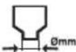 |  | 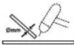 | ||
| (mm) | (A) | (mm) | (mm) | (l/min) | (mm) | ||
| TIG DC | Ss | 0.3 - 0.5 | 5 - 20 | 0.5 | 6.5 | 3 | - |
| 0.5 -0.8 | 15 - 30 | 1 | 6.5 | 3 | - | ||
| 1 | 30 - 60 | 1 | 6.5 | 3 - 4 | 1 | ||
| 1.5 | 70 - 100 | 1.6 | 9.5 | 3 - 4 | 1.5 | ||
| 2 | 90 - 110 | 1.6 | 9.5 | 4 | 1.5 - 2.0 | ||
| 3 | 120 - 150 | 2.4 | 9.5 | 5 | 2 - 3 | ||
| 4 | 140 - 190 | 2.4 | 9.5 - 11 | 5 - 6 | 3 | ||
| 5 | 190 - 250 | 3.2 | 11 - 12.5 | 6 - 7 | 3 - 4 | ||
| Cu | 0.3 - 0.8 | 20 - 30 | 0.5 - 1 | 6.5 | 4 | - | |
| 1 | 80 - 100 | 1 | 9.5 | 6 | 1.5 | ||
| 1.5 | 100 - 140 | 1.6 | 9.5 | 8 | 1.5 | ||
| 2 | 130 - 160 | 1.6 | 9.5 | 8 | 1.5 | ||
FIG. B1
text_image
Technical diagram of a portable electrical device with labeled components including ventilation, heating, and wiring.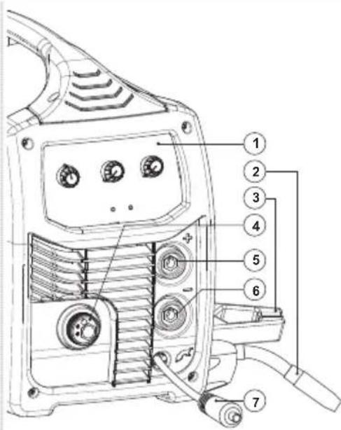
text_image
Technical diagram of a welding torch with numbered parts for identification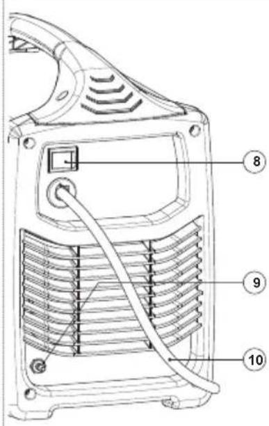
text_image
Technical diagram of a device with numbered parts labeled 8, 9, and 10 pointing to internal components.MIG/MAG (GAS)
text_image
Technical diagram showing cable routing and connector pinout with numbered labels 11 and 12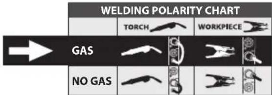
natural_image
Diagram of a cable inserted into a socket with coiled connectors (no text or symbols)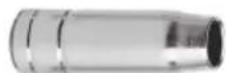
FLUX (NO GAS)
text_image
Diagram showing mechanical linkage with labeled components and numbered parts 11 and 12
natural_image
Pure electrical circuit lines without any symbols
FIG. B2
text_image
Technical diagram of a portable electric shock absorber with labeled parts including wheels, hoses, and control knobs.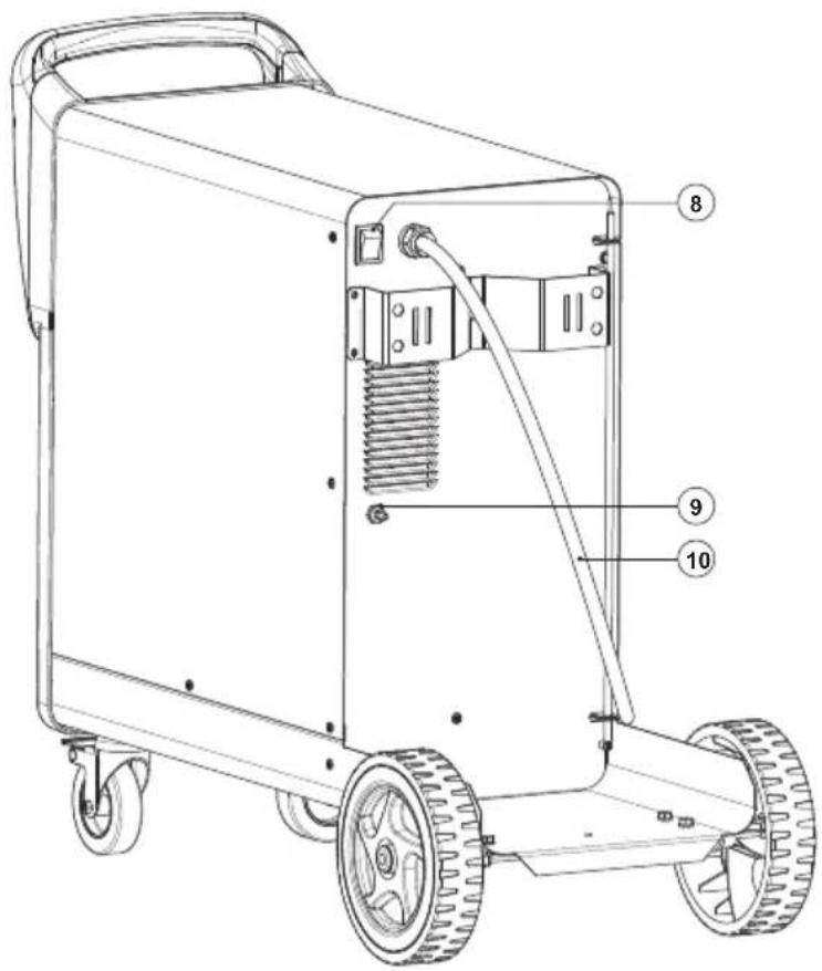
text_image
Technical diagram of a portable electric shock absorber with labeled parts 8, 9, and 10FIG. C
text_image
Synergic 1 2 3 4 5 6 7 8 9 10 A B C D E F G H I J K L M N O P Q R S T U V W X Y Z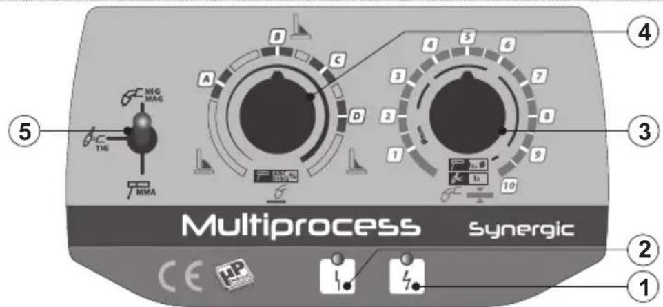
text_image
Multiprocess synergic ① ② ③ ④ ⑤ ⑥ ⑦ ⑧ ⑨ ⑩ ⑪ ⑫ ⑬ ⑭ ⑮ ⑯ ⑰ ⑱ ⑲ ⑳ ㉑ ㉒ ㉓ ㉔ ㉕ ㉖ ㉗ ㉘ ㉙ ㉚ ㉛ ㉜ ㉝ ㉞ ㉟ ㉳ ㉟G MAG T1G MMA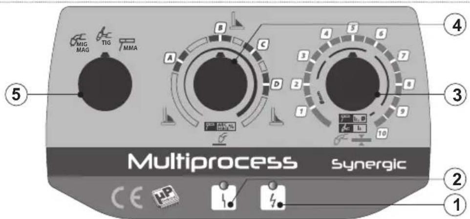
text_image
MIG MAG TIG MMA Multiprocess synergic CE UP 1 2 3 4 5 6 7 8 9 10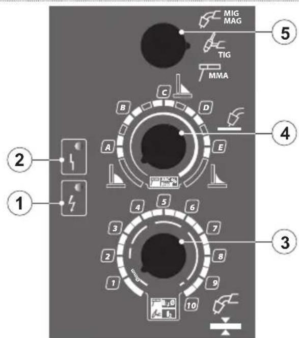
text_image
MIG MAG TIG MMA 2 1 3 4 5 6 7 8 9 10 1 2 3 4 5 6 7 8 A B C D E F G H I J K L M N O P Q R S T U V W X Y ZFIG. D
text_image
N°4 4.8x50 A N°6 M6 F N°8 4.8x13 B N°2 Ø17x35 G N°4 M6x20 C N°2 M6x40 H N°8 Ø64 D N°2 Ø7 L N°6 Ø9 E C D G D E F H L B E F A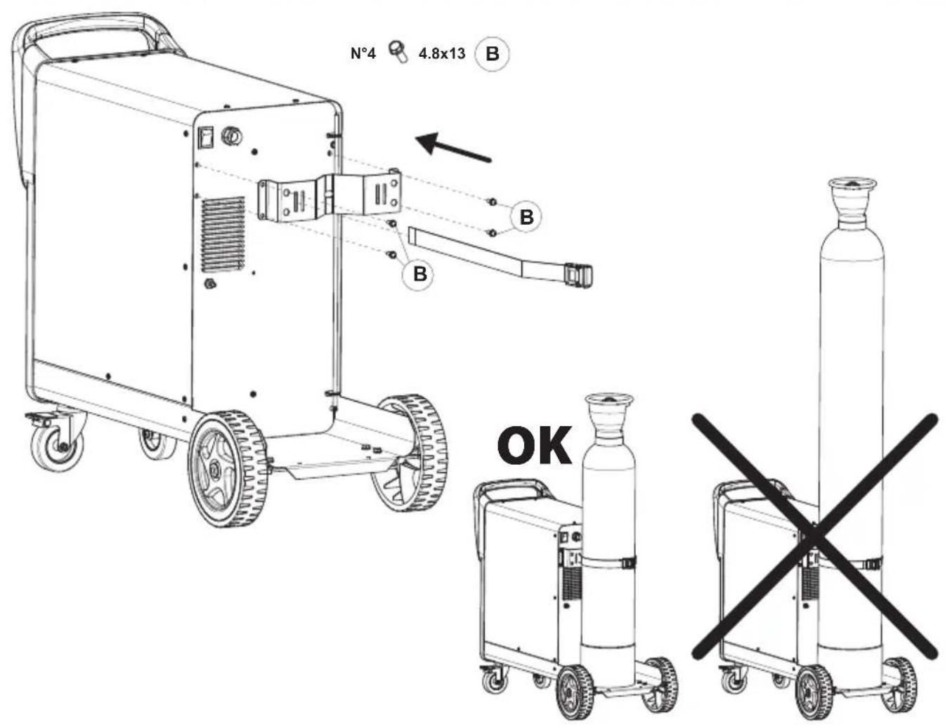
text_image
N°4 4.8x13 B B OKFIG. D1
natural_image
Three technical line drawings of mechanical clamping or welding tools, showing different assembly configurations (no text or symbols present)FIG. D2
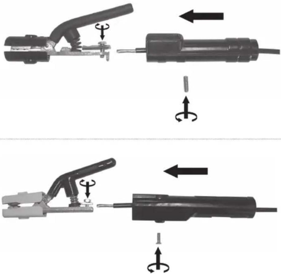
text_image
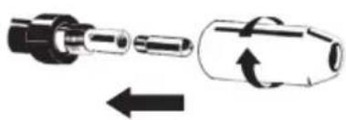
Diagram illustrating the step-by-step assembly of welding torch holders, showing how to switch and rotate the tool.FIG. E
natural_image
Line drawing of a portable industrial machine with wheels and control panel (no text or symbols)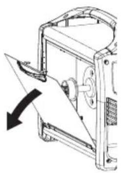
natural_image
Technical diagram of a mechanical device with an arrow indicating direction (no text or symbols present)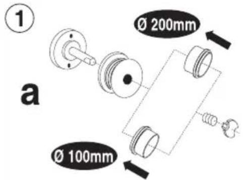
text_image
① Ø 200mm Ø 100mm a②
text_image
b a 0.8 0.8 d c3
text_image
a b4
natural_image
Diagram showing a mechanical component being inserted into a cylindrical housing with an arrow indicating direction (no text or symbols present)a
natural_image
Diagram showing a mechanical component being inserted into a cylindrical housing, with arrows indicating direction (no text or symbols)b
FIG. F
Model: I_2 max = 115A
MIG-MAG / FLUX / BRAZING
| MATERIAL WIRE POLARITY GAS TYPE ROLL WIRE ∅ mm | ∅ | MATERIAL THICKNESS (mm) | |||||||||||
| 0.6 0.8 | 1.0 | 1.5 2.0 | 2.5 3.0 | ||||||||||
| STEELFe | FLUX | NOGAS | 722529 | 0.8 | C | 1.5 | 2 | 2.5 | 3 | 3.5 | 4 | 5.5 | |
| 0.9 | C | 1.5 | 2 | 2.5 | 3 | 3.5 | 4 | 5 | |||||
| STEELFe | GAS | Ar/CO2 | 722019 | 0.6 | C | 2 | 2.5 | 3 | 5.5 | 7.5 | 8 | 9 | |
| 722019 | 0.8-0.9 | B | 2 | 2.5 | 3 | 3.5 | 4.5 | 6.5 | 8 | ||||
| CO2 | 722019 | 0.6 | D | 2 | 2.5 | 3 | 4 | 6.5 | 7.5 | - | |||
| 722019 | 0.8-0.9 | D | 1.5 | 2 | 2.5 | 3 | 4 | 5 | - | ||||
| SSINOX SS INOX | r/O GAS | Ar 2 - Ar/CO2 | 722019 | 0.8 | B | 2 | 2.5 | 3.5 | 5.5 | 7.5 | 8 | 9 | |
| Al | Al | GAS | Ar | 722019 | 0.8 | A | - | 3.5 | 4.5 | 7 | 8 | 9 | - |
| 722629 | 1.0 | A | - | 3 | 4 | 6.5 | 7.5 | 9 | - | ||||
| Zinc Coated | CuSI - CuAl | GAS | Ar | 722019 | 0.8 | A | - | 3.5 | 4.5 | 6.5 | 8 | 9 | - |
Model: I_2 max = 140A
MIG-MAG / FLUX / BRAZING
| MATERIAL WIRE POLARITY GAS TYPE ROLL WIRE ∅ mm | ∅ | G | MATERIAL THICKNESS (mm) | |||||||||||
| 0.6 0.8 | 1.0 1.5 2.0 | 2.5 3.0 4.0 | ||||||||||||
| STEELFe | FLUX | - | NO - GAS | 722529 | 0.8 C 1.5 2.3 | 4.5 6.7 9 | ||||||||
| 0.9 C 1.5 2.7 | 5.5 4.5 6.3 | 8.5 | ||||||||||||
| 722626 1.2 C | 2.2 5 3 3.5 4 4.5 5.5 | |||||||||||||
| STEELFe | GA5 | Ar/CO2 | 722019 0.6 C | 2.5 3 4.5 6 7.5 9- | ||||||||||
| 722019 0.8-0.5 | B 1.5 2 2.5 3.5 4.5 5.5 | 6.5 8 | ||||||||||||
| CO2 | 722019 0.6 D | 2.5 3 4.5 5 7-- | ||||||||||||
| 722019 0.8-0.5 | D 1.5 2 2.5 3 3.5 4-- | |||||||||||||
| SS INOX SS INOX | r/O | GAS | Ar | 722019 | 0.8 | B | 2 | 2.5 | 3.5 | 4 | 5.5 | 7.5 | 9 | - |
| Al | Al | GAS | Ar | 722019 0.8 A | 3.3 5 5.5 7.5 9-- | |||||||||
| 722629 1.0 A | 3.3 5 5.5 7 9-- | |||||||||||||
| Zinc Coated | CuSi - CuAl | GAS | Ar | 722019 | 0.8 | A | - | 2.5 | 3.5 | 5 | 6.5 | 8.5 | - | - |
Model: I_2 max = 180A
MIG-MAG / BRAZING
| MATERIAL WIRE GAS TYPE | ROLL | WIRE ∅ mm | ∅ | MATERIAL THICKNESS (mm) | |||||||||||
| 0.6 0.8 | 1.0 1.5 | 2.0 | 2.5 | 3.0 | 4.0 | 5.0 | |||||||||
| STEEL Fe | STEEL Fe | Ar/CO2 | 722019 | 0.6 | D | 1.5 | 2 | 2.5 | 4 | 6 | 7 | 8 | 9 | - | |
| 722019 0.8-0.9 | C 0.5 1 1.5 2 2.5 3 3 | 5 4.5 6.5 | |||||||||||||
| 722629 | 1.0 | D | - | 1 | 1.5 | 2 | 2.5 | 3.5 | 4 | 5 | 6 | ||||
| CO2 | 722019 | 0.6 | E | 1 | 1.5 | 2 | 3 | 3.5 | 4.5 | 5 | - | - | |||
| 722019 0.8-0.9 | E - 1 1 | 5 2 2.5 3 3 5 4 | |||||||||||||
| 722629 | 1.0 | E | - | - | 1.5 | 2 | 2.5 | 3 | 3.5 | 4.5 | - | ||||
| SS INOX SS INOX Ar/O | 2-Ar/CO2 | 722019 | 0.8 | B | 1 | 1.5 | 2 | 3 | 3.5 | 4 | 4.5 | 6.5 | - | ||
| 722629 | 1.0 | C | - | 1 | 1.5 | 2 | 3 | 4 | 5 | 6 | - | ||||
| Al | Al | Ar | 722019 | 0.8 | A | - | 2.5 | 3 | 3.5 | 4.5 | 5 | 6 | - | - | |
| 722629 | 1.0 | A | - | 1.5 | 2 | 3 | 4 | 4.5 | 5 | - | - | ||||
| Zinc Coated | CuSi-CuAl | Ar | 722019 | 0.8 | B | - | 2 | 2.5 | 3 | 4 | 4.5 | 6 | 6.5 | - | |
| 722629 | 1.0 | C | - | 1.5 | 2 | 2.5 | 3 | 3.5 | 4.5 | 5.5 | - | ||||
FIG. G
natural_image
3D rendered human figure with measurement annotation 'd' (no text or symbols on the figure itself)FIG. H
text_image
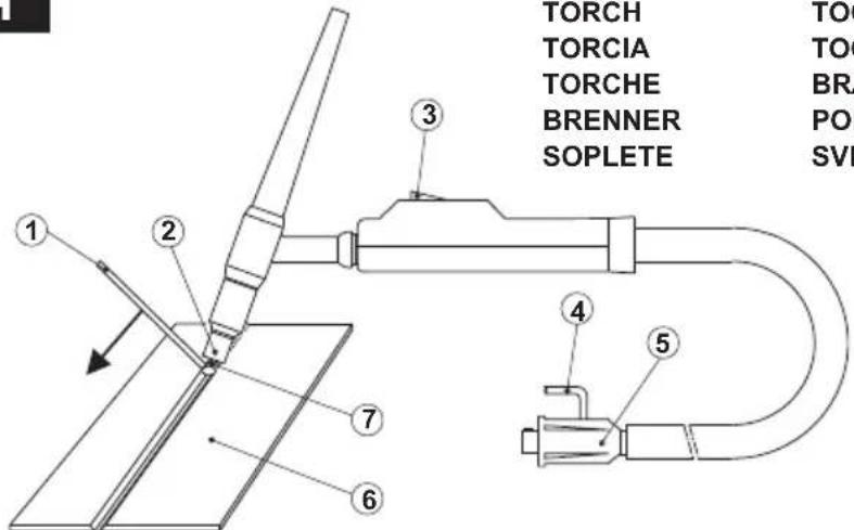
TORCH TORCIA TORCHE BRENNER SOPLETE TOC TOC BR PO SVI ① ② ③ ④ ⑤1- FILLER ROD IF NEEDED - EVENTUALE BACCHETTA D'APPORTO
- BAGUETTE D'APPORT ÉVENTUELLE - BEDARFSWEISE
EINGESETZTER SCHWEISSSTAB MIT ZUSATZWERKSTOFF
- EVENTUAL VARILLA DE APORTE - EVENTUAL VARETA DE
ENCHIMENTO - EVENTUEEL STAAFJE VAN TOEVOER - EVENTUEL
TILSATSSTAV - MAHDOLLINEN LISÄAINESAUVYA - STÖTTEPINNE
- EVENTUELL STAV FÖR PÅSVETSNING - ENDEXOMENH PABДОΣ
EISÄΓΩΓΗΣ - ВОЗМОЖНАЯ ПАЛОЧКА ДЛЯ ПРИПОЯ - قطعة
Costco محتملة
2- NOZZLE - UGELLO - TUYÈRE - DÜSE - BOQUILLA - BICO - SPROEIER - DYSE - SUUTIN - SMØRENIPPEL - MUNSTYCKE - МПЕК - СОПЛО - دوابة
3- PUSHBUTTON - PULSANTE - BOUTON - DRUCKKNOPF - PULSADOR - BOTÃO - DRUKKNOP - TRYKKNAP - PAINIKE - TAST - KNAPP - ПАНКТРО - КНОПКА - زد
4- GAS - GAS - GAZ - GAS - GAS - GÁS - GAS - GAS - GAS - GAS - GASEN - AΔPANEΣ AEPIO - ΓA3- Gaz
5- CURRENT - CORRENTE - COURANT - STROM - CORRIENTE - CORRENTE - STROOM - STRÖM - STRÖM - STRÖM - PEYMA - TOK
تبار
6- PIECE TO BE WELDED - PEZZO DA SALDARE - PIECE À SOUDER
- WERKSTÜCK - PIEZA A SOLDAR - PEÇA A SOLDAR - TE LASSEN
STUK - EMNE, DER SKAL SVEJSES PÅ - HITSATTAVA KAPPALE
- STYKKE SOM SKAL SVEISES - STYCKE SOM SKA SVETSAS
- METAΛΛΟ ΠΡΟΣ ΣΥΓΚΟΛΛΗΣΗ - СВАРИВАЕΜΑЯ ДЕТАЛЬ -
القطعة المراد ل'hامها
7- ELECTRODE - ELETTRODO - ÉLECTRODE - ELEKTRODE - ELECTRODO - ELÉCTRODO - ELEKTRODE - ELEKTRODE - ELEKTRODI - ELEKTROD - ELEKTROD - HΛΕΚΤΡΟΔΙΟ - ЭЛЕКТРОД - قطب.
FIG. I
- CHECK OF THE ELECTRODE TIP
- CONTROLLO DELLA PUNTA DELL'ELETTRODO
- CONTROLE DE LA POINTE DE L'ÉLECTRODE
- KONTROLLE DER ELEKTRODENSPITZE
- CONTROL DE LA PUNTA DEL ELECTRODO
- CONTROLO DA PONTA DO ELÉCTRODO
-
CONTROLE VAN DE PUNT VAN DE ELEKTRODE
-
KONTROL AF ELEKTRODENS SPIDS
- ELEKTRODIN PÄÄN TARKISTUS
- KONTROLL AV ELEKTRODENS SPISS
- KONTROLL AV ELEKTRODENS SPETS
- ΕΛΕΓΧΟΣ ΑΙΧΜΗΣ ΗΛΕΚΤΡΟΔΙΟΥ
- КОНТРОЛЬ НАКОНЕЧНИКА ЭЛЕКТРОДА
- التحقق من طرف القطب الكهري.
text_image
TIG DC Ø L- CORRECT
- CORRETTO
- COURANT
- EXACT
- KORREKT
- CORRECTO
- CORRECTO
- CORRECT
- KORREKT
- OIKEIN
- KORREKT
- ΣΩΣΤΟ
- ПРАВИЛЬНО
-孫حیح
- INSUFFICIENT CURRENT
- CORRENTE SCARSA
- COURANT INSUFFISIANT
-ZU WENIG STROM - CORRIENTE ESCASA
- CORRENTE INSUFICIENTE
- WEINIG STROOM
- FOR LAV STR∅MSTYRKE
- LIIAN VÄHÄN VIRTAA
- DÄRLIG STRÖM
- FÖR LÄG STRÖM
- ANEΠΑΡΚΕΣ ΡΕΥΜΑ
- НЕДОСТАТОЧНЫЙ ТОК
- تيار ضعيف
- EXCESSIVE CURRENT
- CORRENTE ECCESIVA
- COURANT EXCESSIF
-ZU VIEL STROM - CORRIENTE EXCESIVA
- CORRENTE EXCESSIVA
- EXCESSIEVE STROOM
- FOR H∅J STR∅MSTYRKE
- LIIKAA VIRTAA
- ALTFOR H∅Y STR∅
- FOR HÖG STRÖM
- УПЕРВОЛИКО РЕУМА
-ИЗБЫТОЧНЫЙ ТОК - تيار زائد
SKÄRBRÄNNARE
ΛΑΜΠΑ
ГОРЕЛКА
الشعلة
L=∅ IN DIRECT CURRENT
IN CORRENTE CONTINUA
EN COURANT CONTINU
BEI GLEICHSTROM
EN CORRIENTE CONTINUA
EM CORRENTE CONTÍNUA
IN CONTINUE STROOM
VED JÆVNSTR∅M
TASAVIRRASSA
MED LIKSTR∅M
I LIKSTRÖM
ΣΕ ΣΥΝΕΧΟΜΕΝΟ ΡΕΥΜΑ
ПРИ ПОСТОЯННОМ ТОКЕ
في تيار مستمر
FIG. L
natural_image
Pure mechanical cross-section diagram without any text, numbers, or symbols- Preparation of the folded edges for welding without weld material.
- Preparazione dei lembi rivoltati da saldare senza materiale d'apporto.
- Préparation des bords relevés pour soudage sans matériau d'apport.
- Herrichtung der gerichteten Kanten, die ohne Zusatzwerkstoff geschweißt werden.
- Preparación de los extremos rebordeados a soldar sin material de aporte.
- Preparação das abas viradas a soldar sem material de entrada.
- Voorbereiding van de te lassen omgekeerde randen zonder lasmateriaal.
- Forberedelse af de foldede klapper, der skal svejses uden tilført materiale.
- Hitsattavien käännettyjen reunojen valmistelu ilman lisämateriaalia.
- Forberedelse av de vendte flikene som skal sveises uten ekstra materialer.
- Förberedelse av de vikta kanterna som ska svetsas utan påsvetsat material.
- Προετοιμασία των γυρισμένων χειλών που θα συγκολληθούν χωρίς υλικό τροφοδοσίας.
- Подготовка подвернутых свариваемых краев без материала припоя.
The manufacturer guarantees proper operation of the machines and undertakes to replace free of charge any parts should they be damaged due to poor quality of materials or manufacturing defects within 12 months of the date of commissioning of the machine, when proven by certification. Returned machines, also under guarantee, should be dispatched CARRIAGE PAID and will be returned CARRIAGE FORWARD. This with the exception of, as decreed, machines considered as consumer goods according to European directive 1999/44/EC, only when sold in member states of the EU. The guarantee certificate is only valid when accompanied by an official receipt or delivery note. Problems arising from improper use, tampering or negligence are excluded from the guarantee. Furthermore, the manufacturer declines any liability for all direct or indirect damages.