
GCL 215 Professional - Laser pointer BOSCH - Free user manual and instructions
Find the device manual for free GCL 215 Professional BOSCH in PDF.
| Product type | Laser line and point pointer |
| Brand / Model | Bosch GCL 215 Professional |
| Laser line range | 15 m |
| Laser point range | 10 m (vertical up and down) |
| Line leveling accuracy | ±0.3 mm/m |
| Point leveling accuracy | ±0.7 mm/m |
| Self-leveling range | ±4° |
| Leveling time | < 4 s |
| Laser class | 2 |
| Type / Laser color | Red (630-650 nm, <1 mW); version G: green (500-540 nm, <10 mW) |
| Power supply | 3 LR6 (AA) batteries 1.5 V |
| Operating time | 6 to 22 h depending on operating mode |
| Dimensions (without holder) | 112 × 55 × 106 mm |
| Dimensions (with rotating holder) | 132 × 81 × 163 mm |
| Weight | 0.49 kg (according to EPTA) |
| Protection class | IP54 (dust-proof and splash-proof) |
| Operating temperature | -10°C to +50°C |
| Tripod thread | 1/4" and 5/8" |
| Main functions | Horizontal/vertical line projection, plumb points, self-leveling, automatic shutdown after 120 min |
| Rotating holder included | Yes (RM1), 360° rotation |
| Maintenance and cleaning | Clean with a soft, damp cloth; do not immerse; clean the laser outlets regularly |
| Safety | Do not look into the beam; laser class 2; do not modify the laser device |
| Spare parts and repairability | Spare parts available through Bosch customer service; repair by a qualified technician |
Frequently Asked Questions - GCL 215 Professional BOSCH
User questions about GCL 215 Professional BOSCH
0 question about this device. Answer the ones you know or ask your own.
Ask a new question about this device
Download the instructions for your Laser pointer in PDF format for free! Find your manual GCL 215 Professional - BOSCH and take your electronic device back in hand. On this page are published all the documents necessary for the use of your device. GCL 215 Professional by BOSCH.
USER MANUAL GCL 215 Professional BOSCH
All instructions must be read and observed in order for the measuring tool to function safely. The safeguards integrated into the measuring tool may be compromised if the
measuring tool is not used in accordance with these instructions. Never make warning signs on the measuring tool unrecognisable. SAVE THESE INSTRUCTIONS FOR FUTURE REFERENCE AND INCLUDE THEM WITH THE MEASURING TOOL WHEN TRANSFERRING IT TO A THIRD PARTY.
Warning! If operating or adjustment devices other than those specified here are used or other procedures are carried out, this can lead to dangerous exposure to radiation.
The measuring tool is delivered with a warning label (marked in the illustration of the measuring tool on the graphics page).
If the text on the warning label is not in your native language, cover it with the label supplied, which is in your language, before initial commissioning.

Do not direct the laser beam at persons or animals and do not look directly into the laser beam or at its reflection. Doing so could lead to blindless, or could cause acci
dents or damage to the eyes.
If laser radiation hits your eye, you must close your eyes and immediately turn your head away from the beam.
Do not make any modifications to the laser equipment.
Do not use the laser goggles as protective goggles. The laser goggles make the laser beam easier to see; they do not protect you against laser radiation.
Do not use the laser goggles as sunglasses or while driving. The laser goggles do not provide full UV protection and impair your ability to see colours.
Have the measuring tool serviced only by a qualified specialist using only original replacement parts. This will ensure that the safety of the measuring tool is maintained.
Do not let children use the laser measuring tool unsupervised. They could accidentally dazzle someone.
Do not use the measuring tool in explosive atmospheres which contain flammable liquids, gases or dust. Sparks may be produced inside the measuring tool, which can ignite dust or fumes.

Keep the measuring tool and the rotating mount away from pacemakers. The magnets inside the measuring tool and the rotating mount generate a field that can impair the function of pacemakers.
- Keep the measuring tool and the rotating mount away from magnetic data storage media and magnetically sensitive devices. The effect of the magnets inside the measuring tool and the rotating mount can lead to irreversible data loss.
Product Description and Specifications
Please observe the illustrations at the beginning of this oper-
ating manual.
Intended Use
The measuring tool is intended for determining and checking horizontal and vertical lines and plumb points.
The measuring tool is suitable for indoor and outdoor use.
Product Features
The numbering of the product features shown refers to the il- lustration of the measuring tool on the graphic page.
(1) Laser beam outlet aperture
(2) Battery indicator
(3) "Working without automatic levelling" indicator
(4) Laser point mode button
(5) Laser line mode button
(6) Battery compartment cover
(7) Guide groove
(8) On/off switch
(9) 1 / 4 "tripod mount
(10) 5 / 8 tripod mount
English | 17
(11) Serial number
(12) Laser warning label
(13) Rotating mount (RM 1)
(14) Guide rail
(15) Fastening slot
(16) Magnet
(17)Ceiling clip^A
(18) Universal holder (BM1)^A_1
(19) Laser target plate
(20) Case
(21) Inlay
(22) Tripod (BT 150) ^A1
(23) Telescopic shaft (BT350)^_1
(24) Protective bag
(25) Laser viewing glasses
A) Accessories shown or described are not included with the product as standard. You can find the complete selection of accessories in our accessories range.
Technical Data
| Point and line lasers GCL 2-15 GCL 2-15 G | ||
| Article number | 3601 K66 E.. 3601 K66 J.. | |
| Working rangea) | ||
| -Laser line 15 m 15 m | ||
| -Laser point facing up 10 m 10 m | ||
| -Laser point facing down 10 m 10 m | ||
| Levelling accuracy | ||
| -Laser lines ±0.3 mm/m ±0.3 mm/m | ||
| -Laser points ±0.7 mm/m ±0.7 mm/m | ||
| Typical self-levelling range ±4° ±4° | ||
| Typical levelling time <4 s <4 s | ||
| Operating temperature -10°C to +50°C -10°C to +50°C | ||
| Storage temperature | -20°C to +70°C | -20°C to +70°C |
| Max. altitude | 2000 m | 2000 m |
| Max. relative humidity | 90 % | 90 % |
| Pollution degree according IEC 61010-1 | 2b) | 2b) |
| Laser class | 2 | 2 |
| Laser line | ||
| -Laser type | 630-650 nm, <1 mW | 500-540 nm, <10 mW |
| -Colour of the laser beam | Red | Green |
| -Cs | 1 | 10 |
| -Divergence | 0.5 mrad (full angle) | 50 × 10 mrad (full angle) |
| Laser point | ||
| -Laser type | 630-650 nm, <1 mW | 630-650 nm, <1 mW |
| -Colour of the laser beam | Red | Red |
| -Cs | 1 | 1 |
| -Divergence | 0.8 mrad (full angle) | 0.8 mrad (full angle) |
| Tripod mount | 1/4", 5/8" | 1/4", 5/8" |
| Batteries | 3 × 1.5 VLR6 (AA) | 3 × 1.5 VLR6 (AA) |
| Operating duration in operating mode | ||
| -Cross-line and point mode | 6 h | 6 h |
| -Cross-line mode | 8 h | 8 h |
| -Line and point mode | 12 h | 10 h |
| -Line mode | 16 h | 12 h |
Bosch Power Tools
1609924HE|09.08.2018
18|English
Point and line lasers GCL 2-15 GCL 2-15 G
-Pointmode22h22h
Weight according to
EPTA-Procedure 01:2014
0.49kg0.49kg
Dimensions (length × width × height)
- without rotating mount 112 × 55 × 106 mm 112 × 55 × 106 mm
with rotating mount 132 × 81 × 163 ~mm 132 × 81 × 163 ~mm
Protection rating IP 54 (dust and splash-proof) IP 54 (dust and splash-proof)
A) The working range may be reduced by unfavourable environmental conditions (e.g. direct sunlight).
B) Only non-conductive deposits occur, whereby occasional temporary conductivity caused by condensation is expected.
The serial number (11) on the type plate is used to clearly identify your measuring tool.
Fitting
Inserting/Changing the batteries
It is recommended that you use alkaline manganese batteries to operate the measuring tool.
Open the battery compartment cover (6) and insert the batteries.
When inserting the batteries, ensure that the polarity is correct according to the illustration on the inside of the battery compartment.
If the batteries become weak, the battery indicator (2) will flash green. The laser lines will also light up for approx. 5 s every 10 minutes. The measuring tool can still be operated for approx. one hour after the first flash. If the batteries drain completely, the laser lines will flash one more time just before automatic shut-off.
Always replace all the batteries at the same time. Only use batteries from the same manufacturer and which have the same capacity.
Take the batteries out of the measuring tool when you are not using it for a prolonged period of time. The batteries can corrode and self-discharge during prolonged storage.
Working with the RM1 rotating mount (see figures A1-A3)
You can use the rotating mount (13) to rotate the measuring tool 360^ around a central, always visible plumb point. This enables you to set up the laser lines precisely, without having to change the position of the measuring tool.
Place the measuring tool with the guide groove (7) on the guide rail (14) of the rotating mount (13) and slide the measuring tool all the way onto the platform.
To disconnect the measuring tool, pull it off the rotating mount in the opposite direction.
Rotating mount positioning options:
- Standing on a flat surface,
Screwed to a vertical surface, - On metal ceiling strips using the ceiling clip (17).
- On metallic surfaces using the magnets (16).
Operation
Start-up
Protect the measuring tool from moisture and direct sunlight.
Do not expose the measuring tool to any extreme temperatures or variations in temperature. For example, do not leave it in a car for extended periods of time. In case of large variations in temperature, allow the measuring tool to adjust to the ambient temperature before putting it into operation. The precision of the measuring tool may be compromised if exposed to extreme temperatures or variations in temperature.
Avoid substantial knocks to the measuring tool and avoid dropping it. Always carry out an accuracy check before continuing work if the measuring tool has been subjected to severe external influences (see "Accuracy Check of the Measuring Tool", page 20).
- Switch the measuring tool off when transporting it. The pendulum unit is locked when the tool is switched off, as it can otherwise be damaged by big movements.
Switching On/Off
To switch on the measuring tool, slide the on/off switch (8) to the "On" position (for working without automatic leveling) or to the "On" position (for working with automatic leveling). As soon as it is switched on, the measuring tool emits laser beams from the outlet apertures (1).
Do not direct the laser beam at persons or animals and do not stare into the laser beam yourself (even from a distance).
To switch off the measuring tool, slide the on/off switch (8) to the "Off" position. The pendulum unit is locked when the tool is switched off.
Never leave the measuring tool unattended when switched on, and ensure the measuring tool is switched off after use. Others may be blinded by the laser beam.
If the maximum permitted operating temperature of 50^ is exceeded, the tool shuts down to protect the laser diode. Once it has cooled down, the measuring tool is operational again and can be switched back on.
Automatic Shut-Off
If no button on the measuring tool is pressed for approx.
120 min., the measuring tool will automatically switch itself off to preserve battery life.
To switch the measuring tool back on after it has been automatically switched off, you can either slide the on/off switch (8) to the "Off" position first and then switch the measuring tool back on, or press either the laser point mode button (4) or the laser line mode button (5).
Temporarily Deactivating Automatic Shut-Off
To deactivate the automatic shut-off function, hold down the laser line mode button (5) for at least 3 s (with the measuring tool switched on). If the automatic shut-off function is deactivated, the laser beams will flash briefly as confirmation.
Note: If the operating temperature exceeds 45^ , automatic shut-off can no longer be deactivated.
To activate the automatic shut-off function, switch the measuring tool off and on again.
Setting the Operating Mode
The measuring tool has several operating modes which you can switch between at any time:
Cross-line and point mode: The measuring tool generates a horizontal and a vertical laser line as well as two vertical laser points, one facing up, the other down. The laser lines cross at a 90^ angle.
- Horizontal line mode: The measuring tool generates a horizontal laser line in front of it.
Vertical line mode: The measuring tool generates a vertical laser line in front of it.
Positioning the measuring tool in the room displays the vertical laser line on the ceiling beyond the top laser point. If the measuring tool is positioned directly against a wall, the vertical laser line almost encircles the entire space (360^ line).
- Point mode: The measuring tool generates two vertical laser points, one facing up, the other down.
All operating modes, except point mode, can be selected with or without automatic levelling.
Working with Automatic Levelling
| Sequence of actions Horizontal line | mode | Vertical line mode | Point mode "Working without automatic lev-ling" indicator (3) | Figure | |
| On/off switch (8) in position "on" | ●●● | B1 | |||
| cross-line mode | |||||
| + | Press the laser line mode but-ton (5) once | ●-● | C1 | ||
| Press the laser line mode but-ton (5) twice | -●● | D1 | |||
| Press the laser line mode but-ton (5) three times | --● | E1 | |||
| Press the laser line mode but-ton (5) four times | ●●● | B1 | |||
| cross-line mode | |||||
| Point mode can be activated or deactivated regardless of the line mode setting: | |||||
| ● | Press the laser point mode but-ton (4) once | ●/-●/-- | |||
| Press the laser point mode but-ton (4) twice | ●/-●/● | ||||
| If the measuring tool is outside of the self-levelling range, the laser lines and/or points will flash quickly. | If, during work with automatic levelling, you switch to "work- ing without automatic levelling" mode (on/off switch (8) in position "on"), the first combination option of this mode's indicators is always activated. | ||||
Working without Automatic Levelling
| Sequence of actions Horizontal line | mode | Vertical line mode | Point mode "Working without automatic level-ling" indicator (3) | Figure |
| On/off switch (8) in position "on" | ●●- | F1 | ||
| cross-line mode | Red |
Bosch Power Tools 1609 92A 4HE (09.08.2018)
20 | English
| Sequence of actions Horizontal line | mode | Vertical line mode | Point mode "Working without automatic level-ling" indicator (3) | Figure | ||
| + | Press the laser line mode but-ton (5) once | ● -- | Red | |||
| Press the laser line mode but-ton (5) twice | - ● - | Red | ||||
| Press the laser line mode but-ton (5) three times | ● ● - | Red | F1 | |||
| cross-line mode | ||||||
The laser lines continuously flash slowly in "working without automatic levelling" mode.
If, during work with automatic levelling, you switch to "working without automatic levelling" mode (on/off switch (8) in position "On"), the first combination option of this mode's indicators is always activated.
Automatic Levelling
Working with Automatic Levelling (see figures B1-E1)
Position the measuring tool on a level, firm surface or attach it to the rotating mount (13).
For work with automatic levelling, slide the on/off switch (8) to the "on" position.
The automatic levelling function automatically levels irregularities within the self-levelling range of ± 4^ . The measuring tool has been levelled as soon as the laser beams stop flashing.
If automatic levelling is not possible, e.g. because the surface on which the measuring tool stands deviates by more than 4^ from the horizontal plane, the laser beams will flash quickly.
If this is the case, set up the measuring tool in a level position and wait for the self-levelling to take place. As soon as the measuring tool is within the self-levelling range of ± 4^ , the laser beams will light up continuously.
In case of ground vibrations or position changes during operation, the measuring tool is automatically levelled again. Upon levelling, check the position of the laser beams with regard to the reference points to avoid errors arising from a change in the measuring tool's position.
Working without Automatic Levelling (see figure F1)
For work without automatic levelling, slide the on/off switch (8) to the "on" position. When automatic levelling is switched off, the "working without automatic levelling" indicator (3) lights up red and the laser lines flash slowly and continuously.
Switching off the automatic levelling function allows you to hold the measuring tool freely in your hand or place it on a sloping surface. This means that the laser beams no longer necessarily run perpendicular to one another.
Accuracy Check of the Measuring Tool Influences on Accuracy
The largest influence is exerted by the ambient temperature. In particular, temperature differences that occur from the ground upwards can refract the laser beam.
Since the temperature stratification is greatest at ground level, you should mount the measuring tool on a tripod and position it in the centre of the work surface, wherever this is possible.
In addition to external influences, device-specific influences (e.g. falls or heavy impacts) can also lead to deviations. For this reason, check the levelling accuracy each time before beginning work.
First check the height accuracy and levelling accuracy of the horizontal laser line, then the levelling accuracy of the vertical laser line.
If the measuring tool exceeds the maximum deviation in one of the checks, it should be sent to the Bosch after-sales service for repair.
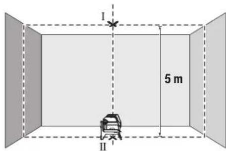
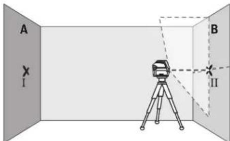
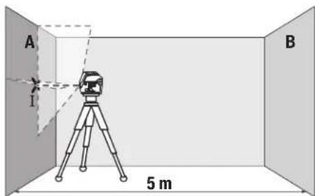
Checking the Height Accuracy of the Horizontal Line
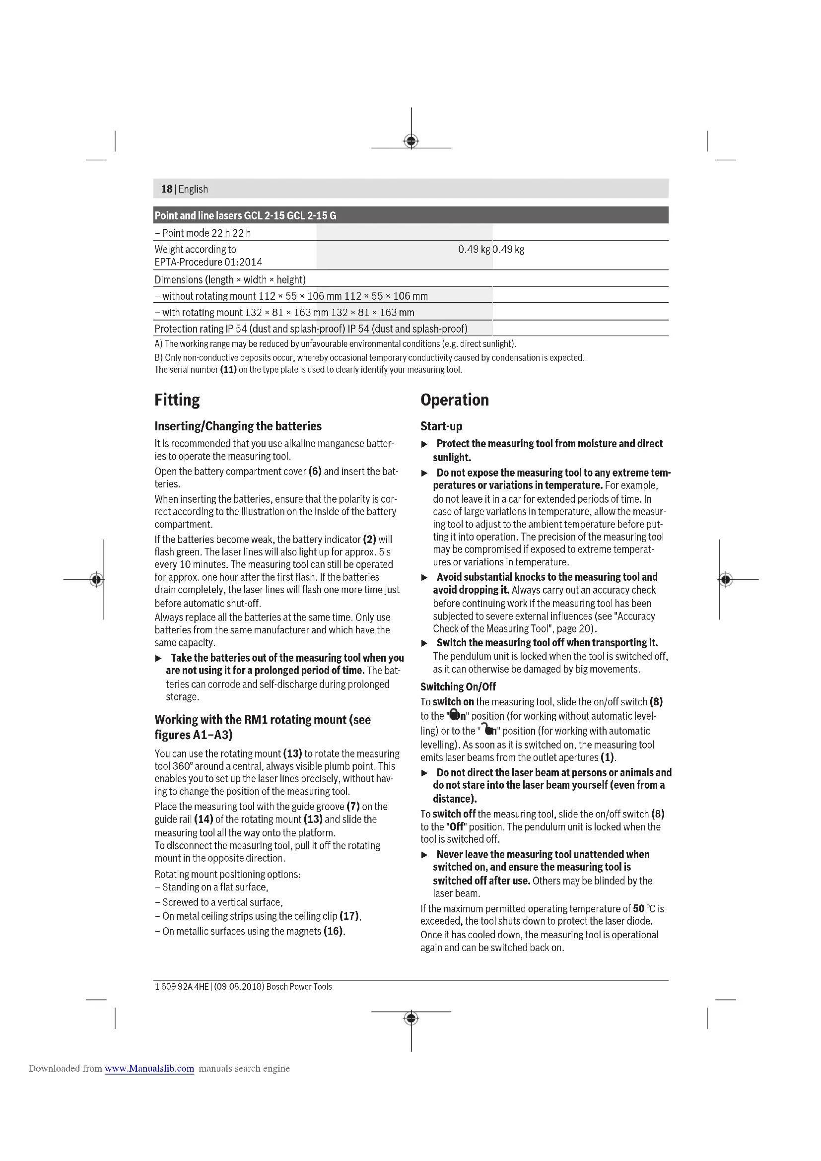
For this check, you will need a free measuring distance of 5 m on firm ground between two walls (designated A and B).
- Mount the measuring tool close to wall A on a tripod, or place it on a firm, level surface. Switch on the measuring tool. Select cross-line mode with automatic levelling.
-Aim the laser at the closer wall A and allow the measuring tool to level in. Mark the middle of the point at which the laser lines cross on the wall (point I).
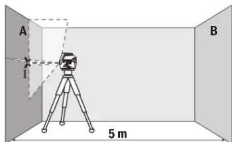
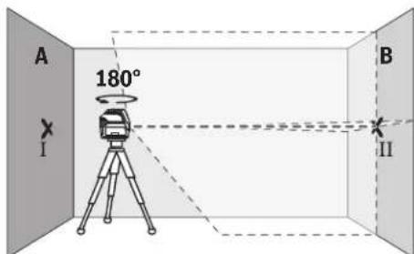
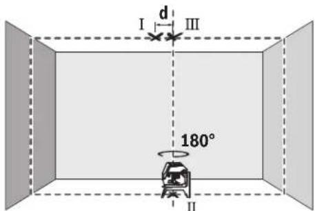
- Turn the measuring tool 180^ , allow it to level in and mark the point where the laser lines cross on the opposite wall B (point II).
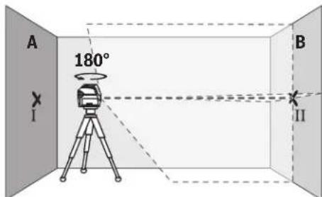
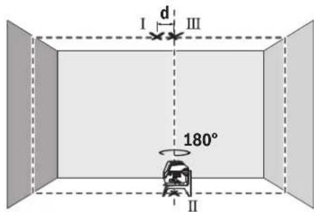
- Position the measuring tool - without rotating it - close to wall B, switch it on and allow it to level in.
Align the height of the measuring tool (using the tripod or by placing objects underneath as required) so that the point where the laser lines cross exactly hits the previously marked point II on wall B.
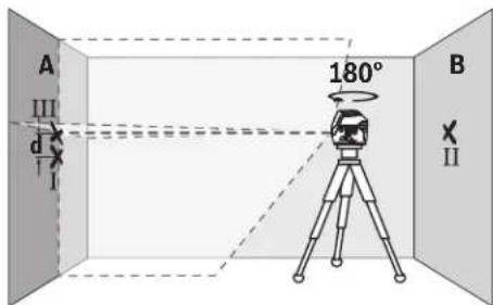
Turn the measuring tool 180^ without adjusting the height. Aim it at wall A such that the vertical laser line runs through the already marked point I. Allow the measuring tool to level in and mark the point where the laser lines cross on wall A (point III).
- The discrepancy d between the two marked points I and III on wall A reveals the actual height deviation of the measuring tool.
The maximum permitted deviation on the measuring distance of 2 × 5m = 10m is as follows:
10 m × ±0.3 mm/m = ±3 mm. The discrepancy d between points I and III must therefore amount to no more than 3 mm.
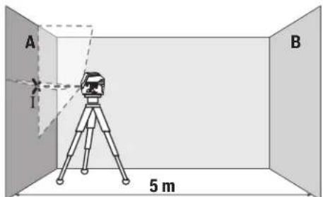
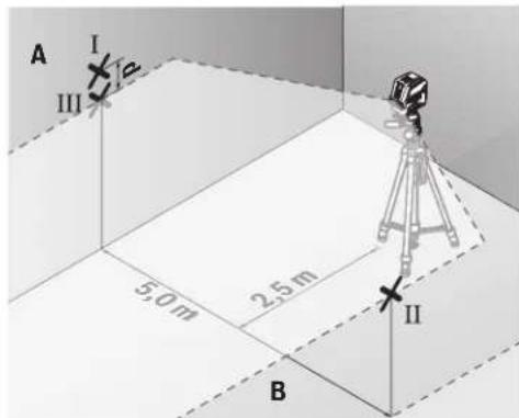
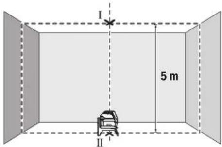
Checking the Level Accuracy of the Horizontal Line
For this check, you will need a free area of 5 × 5m .
- Mount the measuring tool in the middle between walls A and B on a tripod, or place it on a firm, level surface. Select horizontal line mode with automatic levelling and allow the measuring tool to level in.
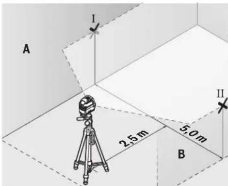
- At a distance of 2.5m from the measuring tool, mark the centre of the laser line on both walls (point I on wall A and point II on wall B).

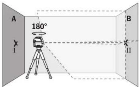
- Set up the measuring tool at a 5 m distance and rotated by 180^ and allow it to level in.
Align the height of the measuring tool (using the tripod or by placing objects underneath as required) so that the centre of the laser line exactly hits the previously marked point II on wall B. - Mark the centre of the laser line on wall A as point III (vertically above or below point I).
- The discrepancy d between the two marked points I and III on wall A reveals the actual horizontal deviation of the measuring tool.
The maximum permitted deviation on the measuring distance of 2 × 5m = 10m is as follows:
10 m × ±0.3 mm/m = ±3 mm. The discrepancy d between points I and III must therefore amount to no more than 3 mm.
22|English
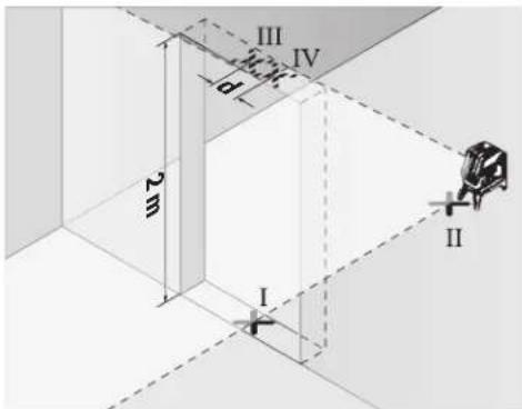
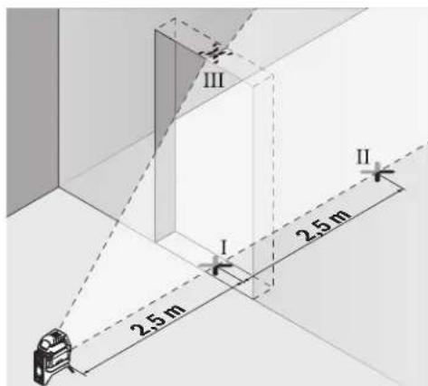
Checking the Level Accuracy of the Vertical Line
For this check, you will need a door opening (on solid ground) which has at least 2.5m of space either side of the door.
- Place the measuring tool 2.5 m away from the door opening on a firm, flat surface (not on a tripod). Select vertical line mode with automatic levelling. Aim the laser line at the door opening and allow the measuring tool to level in.
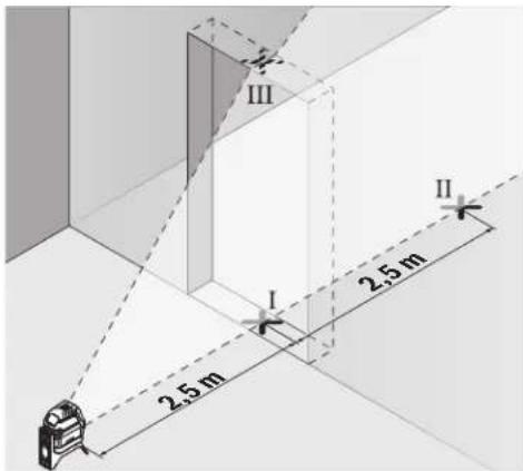
- Mark the centre of the vertical laser line on the floor of the door opening (point I), 5 m away on the other side of the door opening (point II) and on the upper edge of the door opening (point III).
-
Rotate the measuring tool 180^ and position it on the other side of the door opening, directly behind point II. Allow the measuring tool to level in and align the vertical laser line in such a way that its centre passes through points I and II exactly.
-
Mark the centre of the laser line on the upper edge of the door opening as point IV.
The discrepancy d between the two marked points III and IV reveals the actual vertical deviation of the measuring tool.
- Measure the height of the door opening.
You can calculate the maximum permitted deviation as follows:
Doubled height of the door opening × 0.3mm / m
Example: At a door opening height of 2m the maximum deviation amounts to
2 × 2m × ± 0.3mm/m = ± 1.2mm . The points III and IV must therefore be no further than 1.2mm from each other.
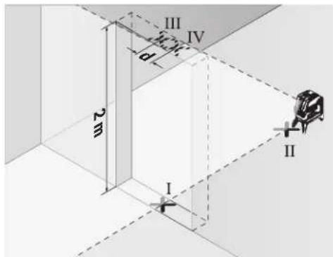
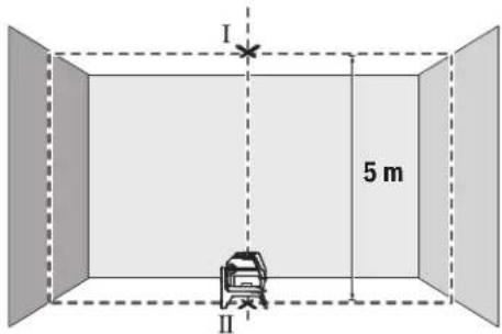
Checking Plumb Accuracy
For this check, you will need a clear measuring space on firm ground with a distance of approx. 5 m between the floor and the ceiling.
Mount the measuring tool onto the rotating mount (13) and place it on the floor. Select point mode and allow the measuring tool to level in.
- Mark the centre of the top laser point on the ceiling (point I). Also mark the centre of the bottom laser point on the floor (point II).
Turn the measuring tool by 180^ Position it so that the centre of the bottom laser point falls onto the marked point II. Allow the measuring tool to level in. Mark the centre of the top laser point (point III).
- The discrepancy d between the two marked points I and III on the ceiling reveals the actual deviation of the measuring tool from the vertical plane.
You can calculate the maximum permitted deviation as follows:
Doubled distance between floor and ceiling × 0.7mm / m Example: At a floor-to-ceiling distance of 5m the maximum deviation amounts to
2× 5m× ± 0.7mm / m = ± 7mm .The points I and III must therefore be no further than 7mm from each other.
Practical Advice
Only the centre of the laser point or laser line must be used for marking. The size of the laser point/the width of the laser line changes depending on the distance.
Working with the Tripod (Accessory)
A tripod offers a stable, height-adjustable support surface for measuring. Place the measuring tool with the 1/4'' tripod mount (9) on the thread of the tripod (22) or a conventional camera tripod. Use the 5/8'' tripod mount (10) to secure the measuring tool on a conventional building tripod. Tighten the measuring tool using the locking screw of the tripod.
Roughly align the tripod before switching on the measuring tool.
Securing with the universal holder (accessory) (see figure G)
Using the universal holder (18), you can secure the measuring tool on vertical surfaces, pipes or magnetizable materials, for example. The universal holder is also suitable for use as a building tripod and facilitates height adjustment of the measuring tool.
Roughly align the universal holder (18) before switching on the measuring tool.
Working with the Laser Target Plate (see figure G)
The laser target plate (19) improves visibility of the laser beam in unfavourable conditions and at greater distances. The reflective half of the laser target plate (19) improves visibility of the laser line. The transparent half enables the laser line to be seen from behind the laser target plate.
Laser Viewing Glasses (Accessory)
The laser viewing glasses filter out ambient light. This makes the light of the laser appear brighter to the eye.
Do not use the laser goggles as protective goggles.
The laser goggles make the laser beam easier to see; they do not protect you against laser radiation.
Do not use the laser goggles as sunglasses or while driving. The laser goggles do not provide full UV protection and impair your ability to see colours.
Example Applications (see figures B2-F2,G and H)
Examples of possible applications for the measuring tool can be found on the graphics pages.
Always place the measuring tool close to the surface or edge that needs to be checked, and allow it to level in before the beginning of any measurement.
Always measure the distances between the laser beam and a surface or edge at two points that are as far from each other as possible.
Maintenance and Servicing
Maintenance and Cleaning
Keep the measuring tool clean at all times.
Never immerse the measuring tool in water or other liquids.
Wipe off any dirt using a damp, soft cloth. Do not use any detergents or solvents.
The areas around the outlet aperture of the laser in particular should be cleaned on a regular basis. Make sure to check for lint when doing this.
After-sales service and advice on using products
Our after-sales service responds to your questions concerning maintenance and repair of your product as well as spare parts. You can find explosion drawings and information on spare parts at: www.bosch-pt.com
The Bosch product use advice team will be happy to help you with any questions about our products and their accessories.
In all correspondence and spare parts orders, please always include the 10-digit article number given on the nameplate of the product.
Great Britain
Robert Bosch Ltd. (B.S.C.)
P.O.Box 98
Broadwater Park
North Orbital Road
Denham Uxbridge
UB95HJ
At www.bosch-pt.co.uk you can order spare parts or arrange the collection of a product in need of servicing or repair.
Tel. Service: (0344) 7360109
E-Mail: boschservicecentre@bosch.com
Ireland
Origo Ltd.
Unit 23 Magna Drive
Magna Business Park
City West
Dublin 24
Tel. Service: (01) 4666700
Fax: (01) 4666888
Australia, New Zealand and Pacific Islands
Robert Bosch Australia Pty. Ltd.
Power Tools
Locked Bag 66
Clayton South VIC 3169
Customer Contact Center
Inside Australia:
Phone: (01300) 307044
Fax: (01300) 307045
Inside New Zealand:
Phone: (0800) 543353
Fax: (0800) 428570
Outside AU and NZ:
Phone: +61 3 95415555
www.bosch-pt.com.au
www.bosch-pt.co.nz
Republic of South Africa
Customer service
Hotline: (011) 6519600
24 | Français
Gauteng - BSC Service Centre
35 Roper Street, New Centre
Johannesburg
Tel.: (011) 4939375
Fax: (011) 4930126
E-mail: bsctools@icon.co.za
KZN - BSC Service Centre
Unit E, Almar Centre
143 Crompton Street
Pinetown
Tel.: (031) 7012120
Fax: (031) 7012446
E-mail: bsc.dur@za.bosch.com
Western Cape - BSC Service Centre
Democracy Way, Prosperity Park
Milnerton
Tel.: (021) 5512577
Fax: (021) 5513223
E-mail: bsc@zsd.co.za
Bosch Headquarters
Midrand, Gauteng
Tel.: (011) 6519600
Fax: (011) 6519880
E-mail: rbsa-hq.pts@za.bosch.com
Disposal
Measuring tools, accessories and packaging should be recycled in an environmentally friendly manner.

Do not dispose of measuring tools or batteries with household waste.
Only for EU countries:
According to the Directive 2012/19/EU, measuring tools that are no longer usable, and according to the Directive 2006/66/EC, defective or used battery packs/batteries, must be collected separately and disposed of in an environmentally correct manner.
François
Calle Robert Bosch No. 405
C.P. 50071 Zona Industrial, Toluca - Estado de Mexico
Tel.: (52) 55 528430-62
Tel.: 800 6271286
Bosch Service Center
Telegrafvej 3
2750 Ballerup
Pá www.bosch-pt.dk kan der online bestilles reservedele el-ler oprettes en reparations ordre.
TIf. Service Center: 44898855
Fax: 44898755
E-Mail: vaerktoej@dk.bosch.com
Bortskaffelse
Bosch Service Center
Telegrafvej 3
2750 Ballerup
Danmark
Tel.: (08) 7501820 (inom Sverige)
Fax: (011) 187691
80|Norsk
Avfallshantering
Stille inn driftsmate
Epyaia TovTpinoda (eapnma)
O tpinodac anotealeia staoteepn oto uoc pueoieevn faon metpnanc. Tonoetane to opyavo metpnanc me tvu unoooh tpinoda 1/4" (9) 0to aneipwma tou tinopa (22) n evoc tpinoda va qtoypapikn npxavn tou eunopiou. Ta tn stepewan oe evav dojktoptinoda tou emnpiou xpnaonoiire treuv unooxynptina 5/8" (10). Bibwote to opyavo metpnanc me tn bida auaqiync tou ptinoda strhepa. Puoblate kata npoeeyiontov tpinoda npotou everpyoonihete to opyavo metpnanc.
Tepeown me to tniipiyya yevikic xponc (ekaptnma) (BLe n ckova G)
MeTnBOntheuOtnpIyauoCyeVikncxponc(18)mopeite vaotepeoateTooyavoetponancn.x.aceKaTeec enpaiveie,awlnevocnoayvntiopevaulka.Hbaon yevikcxponcmuopei enianocvaXpoaunoinei kai aav Tpoiaocdanedou,payuaoudieukolueivny Euypuamionto uocouoyavou metponc. Euuypaumte kata npoeayian to tnpiyua yevikncxponc (18),npotou evpyonoioteTooyavoetponc.
Epyaia je tv nivaka toxou lezep (bAeTe eikoVa G)
O nivakac oixou yia lecep (19) beaowei tv opatotnra tnc akivaac lecp ae duoeveic ouvohkek kayeyalec anoataeic.
To avakaaotko mao tou nivaka otoxou aecep (19) baleuov TnV opatotnta TNC aktiva aecep, ME TO diaqavec hmuou avaywpiietai n akrtiva aecep enionc kai ano Tnv niow nneupa tou nivaka otoxou aecep.
Tuaia (aεεσouap)
Ta yuaia napatponanc lecep pfatapouv to ooc tou nepiabalovtoc. Eta biakpiveta kuletpa to ooc tou lecep.
Mn xnpouonoeite ta yuaia alecp o npootateutka yuaia. Ta yuaia alecp xnpoueuov yia tvkaupepn avaywupion nnc aktivaac alecp, aaaa owc dev npootateouv ano tvn aktiva alecp.
Mnxpnooie Ta yuaia Aetep wyaia naiou n 0yn obik kukloopopia. Ta yuaia alecp dev npooepouv nipnp npostria an no tny unepiobn akivobolia kai peiwov tvn avriann twxpwpatw.
Tapadeiyama copyoadic (Bene eukovc B2-F2,GkaiH)
Papabeiyama duvatoTtwy xonc tou opyavou mtpnonc Ta Bpeite ot c aeidec me ta ypaqka.
TOnotheTeIeTo opyavo metpncn navtoe kovta otnv enpaevia nakn, nou npenei va eayxgei, kal aphiote to va xwpotaunotie npiv nvy evapenk ahe metpnan.
Metphote tic anoataeic avaeaa otnv akiva leiep h, avaloya, avaeaa otnv akiva leiep kai oe duo anieia, ooo to duvato nio jakpiia to eva and to aho.
Suvtnponon kal oepic
Uvtnponn kkaaapiaoc
Na diatnpieTe to epyaioe npnnc nVrta kaqap. Mn BuIooTeTo epyaioe npnnc oe vepn ae aaauypa.
KaBapicete TuXov punavon ^ eva uyo, paako nvl. Mn xnpounoihoente kaveva uyo kaBapiauou h diautn. Na KaBapicete TAKIka idaiptepa tic enipaveiec kovta otny eEdoTNC akltvac aeiecpa va npoeexet va un 6nmuoyouvtai xvobia.
Eumnpertnon nearov kaioupoue cepapoyic
To tunu eunnpetnnc neataw anavra otic epwnnoe oac oxetika me nyn eniakeun kal tn ouvtnpon tou npoiovtoc aoc kaowc kai yta avlatoxa avtalaakntka. xedia uvaupoaoynanc kai napopopiec yia ta avtaalakntika 8a Bpiete emionc katw an: www.bosch-pt.com H ouda napoxhc oumuouwv tc Bosch anavta euxapiotuc tic epwnthoeic oac yia npovta mac kai ta egaptmata touc. Awote oe olec tic epwnthoeic kai npayyalec avtaalakntkw onwaohnote tv 10nphi kwdi opbiog oipwmae nivakida tunou tou npoiovtoc.
EAAa
Robert Bosch A.E.
Epxciac 37
19400Kopwni-Ahiva
Tnλ.: 2105701258
DgE:2105701283
www.bosch.com
www.bosch-pt.gr
ABZ Service A.E.
Tnλ.: 2105701380
Qaξ:2105701607
Anoupon
Ta opyava mepnanc, ta eapntjata kai ooukeuaie npenei va avakukawovtai pe Tpno piaiko npoc to nepiabllov.

Mn pixvetata opyava metpnonc kai tnc npatapie c oiaikak anoppmuata!
Móvo yu xópec tnc EE:
Uuwpva uTyn EupwnaiKn obnyia 2012/19/EE ta dxnpora opya uTpnoi c kai uwpwa u Tyn EupwnaiKn obnyia 2006/66/EK oXalaouevc hxpauonoiuevec matarpiec dev eivn Aoeunooxpewtko va ouAevovtai Exwpia Ta va avakukawOuv uTpo nio pnc to peipalov.
Türkce
Güvenlik talimati

Robert Bosch Sp. z o.o.
Bosch Service Center PT
K Vapence 1621/16
692 01 Mikulov
Na www.bosch-pt.cz si si muzete objednat opravu Vaseho stroje nebo nahradni dily online.
Data n3roTOBnEHnYkA3aHa Ha noCneJeHcTpaHnue 06-LOKKN PykoBOCTBa HnHa KOpnyce n3denHn.
KoHTaKTHaHnHΦOpMaunr OTHOCHeNbHO HmNopTepa coepKHTcHa ynaKOBKe.
Cpok cnyXbI n3dennn
Cpok cnky6b H3eHnH coctabniet 7 net. He peKoMeHnyet c K3cNpyataunno nCTeueHH 5 net xpaehnnc DaTbI H3rTOBHeHH 6e3 npedapntelbHOIN POBepKN (DAty N3rTOBHeHH CM. Ha 3TNKeTke).
IpeueeHb KPNTHueckx OTKa3OB H OwH6OuHbIe DeiCTBnepcoHaHa HnN NOnb3OBaTeNa
-HeHCIOB3OBaT npnIOABLeHHn Dbima HEnOcpeCTBeHHO N3 Kopnyca N3dennr
-HeHCIOB3OBAHHaOTKpblOMPPOCTpaHCTBEBOBPEMdoJRA(BpaCnblnREMOB0e)
-He BKNIOUaTb PnI NOIaHIN BOBb I KOpNc
Kpntepnnnpedebnbixcoctoannn
- noBpeKdEn KOpNc N3dennn
TnH nepnoDnHocb texHHueckoro 06cnyxHBaHHN
PekomeHcyTeoOHCTb HNCTpyMeHT OT nbINn Nocne KaK-DOHOHCNOB3OBAHH.
Xpahenne
-Heo6xOIMO xpaHnTB CcyOM mecTe
-Heo6xOIMO xpaHnB Bann OT NCTouHKnOB NOBbIeH HbIX Temnepatyp IN BO3dEChTBnCINHeuHbIX NyueH
- npxpaHenn Heo6xoJnMo H36eraTb pe3KOrO nepenada TEmnepatyp
-eCNHHTPYMEHT NOCTABNIETCB MRAKO CYMKE HINIIA-CTKOBOM KECE peKOMEHnyETC XpaHHTb HHTPYMEHT B 3TOI 3aunTHOYNAKOBKE
- noDpObHbIe Tpe6oBaHHaK YcNoBnM XpaHeHHa CMOtpnte BTOCT 15150 (YcNoBne 1)
TpaHcnpToHpOBka
KaTeROpUeCckn He IOnyUcKaetcnaIaeHne IIObIbe MxaHueckHe Bo3dEChTBnHa YNaKOBky npN TpaHCnOpTnpoBKe
- npn pa3rpy3ke /noIrpy3ke He IonycKaetc HcNoIb3OBAHHe IIO6oB Yo Bua TeXnKn, pa6oTaioeN No npHHuNy 3aJkMa yNaKOBKn
144|Pycckn
- noDpObHbIe Tpe6oBaHnK yCIOBnM TpaHCnpTnPOBKn CMOTPHe B FOCT 15150 (YcNOBne 5)
Yka3aHHnNo TexHnke 6e3oNaCHOCTN

Ja 06ecneueHH 63oNaCHOH HaedKHOI pa6bI c H3MePHTeHbIM HcTpyMeHToM dONXHbI 6bITb IpOHTaHbI cOBnIOdaTbcB BCE HHCTpyKUHN. HcNoJIb3OBAHHe H3MepeH
TeNbHOro HNCTpyMeHTa He B COOTBETCTBN C HAcTOnuMH Yka3aHHMaH NpeBaTO NOBpeXJeHNEM HHTerTpPoBaHbX 3aunTHbIX MexAHn3MoB. HNKOrda He H3MeHnIe Do Hey3HaBaemocTN IpeynpeHntbHbIe Ta6nUKN Ha H3-MepHTenbHom HNCTpyMeHTe. XOPOUO COxPAHNTE 3TN IHCHPYKUN INPEPDABAITE INX BMECTEC INPEPDAA4EN H3MEPHTeJIbHOrO HNCTpyMeHTA.
Octopoxho-npHMeHeHHe HcHtpMeHOBnIgO6cyXHBAHHHNIOCTHPOBKNHINPPOeDyTpExo6cnYxHNBaHHKpOMe yKa3aHHbIX 3Decb,MOKeT pNHBeCTN KOnachomy BO3dEChTBHO3NyueHH.
H3mepHTenbHn HnCTpyMeNT nOCTaBnTcTa C npedynpdHTeBHO TabNtKoN (nokaHa Ha cTpaHnue Cn06paXeHHem H3mepHTenbHoro HnCTpyMeNTa).
EcHn TeKCT npDynpTeNTbHOI Ta6NHyHe Ha BaWem poHOM 33biKe, nepe nepBbIM 3anyckom B3KcNpyatauHIO 3akneIe ee hakneiKOHa BAWeM poHOM 33biKe, KOtopaBxOHTB O6bEM NoCTaBN.

He HanpaBnIe lyu na3epa Ha IIOeHnn KBNBoTHbIX H cam He cMOTpHTe Ha pIpmO Hnn Otpaxaembl nyna3epa. 3OT Lyu MoKET CInNTb IIOeH, CTaTb PnHHoH He
CuaCTHOrO CnyaA HIN NOBpeDntb rna3a.
Bcnyae nonadHnna3epHoro nya B rna3rnana3a HxKHO HamepeHHO 3akpbItb H HEmedneHHO OTBepHYbcnOTnya.
He MeHnTe HmUeB Nla3epHom yctpoNCTBe.
He nCnoB3yIte OUKN DnPa60tbc Na3epom B KaueCTBE 3aunTHbIX OQKOB.OuKnDnpa60tbc Na3epoM oBeceNeuBAOT Lyuwee pacNo3HaBaHne Na3epHoro Lyua, HO He 3aunuAOT OT Na3epHoro N3nyehn.
He mncnbl3yte oukndpa60tbcnaepomBkaeCTBe cOnHce3aunTHbIX OOKOB Hnn 3a pyneM.OuKn dpa60tbcnaepom He oecneuBAOT 3auHTy OT yΦ-n3ny-ueHHN MEsaot npabINbHOMY CEBTOBCPnTHO.
Pemont H3MepHTeBHO INCTpyMeTHa pa3peaetc BbIOHnBTb TOnbKO KBaHnHpOBaHHOMy NepcoHany HToBko C HcTIOB3OBAHHem OPHrHaNbHbIX 3Ana-CTeH.3TNMO6ecneuBaETc8e3oNaCHOCTb H3MepHTeBHO INCTpyMeHTa.
He No3BONJIte DeTAM NOnb3OBAbTaCn Na3ePbHIM H3-MepHTeNbHbIM HcHTpyMeHToM 6e3 npHcMoTPa. Detn MOryT NO HeoCTOpOXHOCTN OCLENITb NOCTOPOHHX IHO-Dei.
He pa6otaTe cH3MePHTeNbHbIM HcHTpyMeHToB B3pbBOoNacHOcpe, noBnH3OCTn OTropHOnxKIOKcTe,ra3OBnblIN. B3MepHTeNbHOM HcHTpyMeHTo
MORYo6pa30BaTbCnHckpbI,OTKOTOpbIXMOXeTBOcIIaMeHHbCnBnBnNnnapbl.

HcTahabnBaIte H3MePHTeBbI HNCTpyMeH NOBOPOTHe KpENNEHe B6IN3N KapHNOCTHMnTOpOB.MaHHTbI H3MePHTeBHOrO HNCTpyMeHTa N NOBOPTOHO KpENNEHc CO3aIOT NONE, KOtPOE MOKeT OTPuATeBbHO BnHrtb Ha pa60Ty KApDIOCTMnTOpa.
DepxHTe H3MePHTeBbHb HnCTpymEt N NobopoTHoe KpennHe BdAnHOT MaHHTbIX HOCHTeNe DaHHbIX N OT npH6OpOB, YyBCTBnEbnBbIX K MaHHTHOmy NOIO. Bo3JeCTBnE MaHHTOB H3MePHTeBbHOrO HnCTpymEtHa N NobopoTHOrO KpennHeMooKet PnHBecTn K Heo6paTM MoI NOtepe daHHbIX.
OnncanHe npoodykTa n ycnyr
PtoKaIyIcTa,co6IIOaIte HIIIOCTpaunB Hauane pykoBOIDCTBaNo3KcIpyataun.
PpHMeHeHHe no Ha3HaueHHIO
H3MePntelbHbI HNCTpyMeHT npEHa3NaueH IaONpeDeneHHI NPOBepKn rOpN3OHTaJIbHbIX IN BepTKaJIbHbIX IINHHIOTBecOB.
H3MePntbHbI HNCTpymeTnPiFOeHdIpaBtBI BHTPNOMeueHnHaOTKpbITOMBO3dyxe.
H306paXeHHbIe COCTaBHbIe qACTn
HymepaunipnepctabneHHbIXcoCTabHbIXyacteBblonHeHa no 1306paXeHHIO h3MePHTeNbHO HhCTpyMeHTa Ha cTpaHnCe CnnHIOCTpaIHNM.
(1) OTeBepCTneIaIbXbOJaIa3epHOrO lyuA
(2) NHHaKatop 3apaeKeHHocTH 6baTapeek
(3) INHdkatop pa60tby 6e3 ABTOMaTHueCKOTo HHe-
(4) Khonka pejxima pa60tby «Jazepna Toyka»
(5) KhoNka pexkma pa60tBu 1a3epHa nHHnA
(6)Kpbuika 6aTaapeHoro OTecka
(7) HanpaBnaIouni na3
(8)BbIKNoaTeNb
(9)「he3do noiWtaTbV 1/4"
(10) THe3IO NOI WtATINB 5/8"
(11) CepnHbH HOpem
(12)PpeDynpedntelbHa Ta6nUka na3epHoro n3ny-
(13)Поворот Shoe Kpenlenne(RM 1)
(14) Haprablaiouapeika
(15)Пюдог罗ва toe Кренихhoe OTBepcthe
(16)MaHTnT
(17)ПOTOnOuHаСкоба
(18) YnHbepcaIbHoe KpenneHHe (BM 1)
(19) Bn3npna Mapka dI na3apehro IyuaA
Pycckn|145
(20) yt p^[A]
(21)BknaIabIw
(22) ⅢTaTnB (BT 150)
(23) Teneckonuueckn wecr (BT 350) ^A)
(24)3aunHthnyuexon
(25) OuknДЯр pa6oTbI cIa3ePbHIM HHTcpyMeHToM
A) H3o6paXeHHbIe HnONcAHHbIe npHaJNEXHOCTHe BxOaHTB CTANAPHTbIb O6bEM NOCTABKN. NOnHbI accOPTMENT npHaJNEXHOCTe BbHaDete B Haae npPorpMaMe npHaJNEXHOCTe.
TexHHueckne daHHble
Odno3haHn HteHnKauHn H3MePHTeNBHO INCTpyMeHTa BO3MOxHa No cepnHOMy Homepy (11) Ha 3aBODcKo Ta6nHKe.
C6opka
BCTABKa/3aMeHa6aTapeek
B H3mepntenbHom HnctpymEnTe peKOMeHnyetcHcNtob30-Batu eNoOH-mapraHueBbIe 6aTapeKn.
OTKINbTe KpbIuKy 6aTaapeHOrO OTceKa (6) N BCTaBBte 6aTapeKN.
CnneHte npn 30m 3a npaBnIbHbIM HanpabNeHem NOIOcOB B COOTBeTCTBn C N3o6paKeHEm C BHyTppeHHe CTOpOHbI 6atapeHoro OTceKa.
Ecnb batapekn HauHaiot caHtbcn, npedynpexdene H Opa3r4ke bataapeek (2) Mrraet 3eneHbIM. B donoIHeHne K ATOMy Ia3ephe NHHMHraOt npHb5.5c HHTepBaONB 10 mH. Pocne hauana MuaHn H3MePHTeBbH INCTpyMeHT MOKeT paboTaB eue OK. 1aca. Ecnb batapekn ceN, Ia3epHbte NHHMIRAOt eue OHN pa3 HeNoCpeCDTBehHO npepd ABOTMATueckHM OTKJUQHeHEM.
MeHnTe cpa3y Bce 6batapeKKn OndHOBpeMeHNo. NcnoIb3yTe ToIbko 6batapeKKn OndHOrO npOn3BOdnteN OndHaKOBoE MKOCTH.
H3BneKaTe 6aTapeKn H3MepHTeNbHO HNCTpyMeHa,ecnn npOOnXeTbHoe BpeMa He 6yTe pa6oTa b c Hm. Pn dInTeJbHOM xpaHeHH BO3MOxHa Kopp03n n camopaaPka 6aTapeek.
Pa6ota c noBopOthbIM KpeIeHHem RM1 (cm.pnc.A1-A3)
PnnoMOOnIO NOBOPoTHOrO KpEnIeHnA (13) H3MePHTeNbHbINHCTpyMeHT MoXHO NOBOPaUNBaTb Ha 360° BOKpy TcHtpaJIbHO, NOCTOBHH BOHNMO OCN OTBeCA. 3TO N03BOJReT TOHO HAcTPOTh Ba3epHbIe IHHH, He INMeHRA NIOJOKeHHe IN3MePHTeNbHO IHCTpyMeHTa.
PnHCTaBbTe H3MePHTeBbHInHCTpyMeHT HaPiabNIOUIM na3OM(7)KHaPpABNoUepeKe(14)NOBOPOTHOrO KpenIeHHA(13)INCTaBbTe H3MePHTeBbHInHCTpyMeHT DO ynpa HA NOBOPOTHyIpaTfOpMy.
IIN CHTIN NOHTHNE H3MEPHTeBbH INCTpyMeNT BOBpaTHOM HAPABNEHN C NOBOPOTHO KpENNEHNA.
Bo3MOxHocTHnNo3NIOHOHPoBaHHn NOBOPoTHOro KpennneHHN:
-CTOHaPOBHOH NOBepxHOCTH,
-πpHKpyeHoK BepTKaNbHOnΠnOcKoCTN,
-B CoeINHeHH CNOTOIOHCHKOB0I (17)B NOBWeH HOM COCTOHH HA MetaJIHueCKOH NOTOIOHOpEKe,
- npnKpeHneHO MarHHTAMN (16) K MetaJIInueCKoI NOBepx-HOCTN.
Pa60Ta c HcTpymeHTOM
BklioueHne 3nEkpomHcTpyMeHa
3aunuHTe H3MePHTenbHbHn HnCTpyMeHT OT BnArn npMbx COHeuHbIX Nyei.
He noDBeBpaTe H3MepeHtBbHbHn HnCTpyMeH T03-DeHCTBnO 3KCTpeMaIbHbIX TempeaTp H TempeaTpybIX nepenaoB. HanpmeP, He octabnIte ero Ha nnTeBHO BPEM BAOTOMoBnE. Pn 3HaunTeBbIX KOeBaHNX TempeaTpBy nped HAJONbBOHa Hn DaIe Te TempeaType H3MepeBbHOrO HnCTpyMeHTa CTaBnHnHPOBaTcB. 3KCTpeMaIbHbIe TempeaTpBy n TempeaTpByne nepenadby MOrY OTpHuaTeBHO BnAHTb Ha ToHocTh H3MepeTbHOrO HnCTpyMeHTa.
H36eAHTe CnIbHbIX TOnyKOB NJaDEHn H3MePHTeBHO HOHCTpymEHa. Nocne CInbHbIX BHeUHIX Bo3deN CTBN HA H3MePHTeBbHbIN H3CTpymEHT peKOMeHnyETc npOBepNTb erO ToHOCb, npExKe Yem npoJOnjKaTb paBoTaTb c H3CTpymEHTOM (CM., KoHTpOJIb ToHOCtN H3MePHTbHO HOHCTpymEHa", CtpaHnca 148).
Pn TpaHcnpTnpOBKe BbIKIOaHTe H3MepeTebhBn HNCTpymEn. Pn BbIKIOueHN 60KINpyETCA MaTHN- KObIM MEXaHN3M, KOTOpB INHaue pN cINbHbIX DBNXeH NAX MOKeT 6bITb NOBpeXdEh.
BkIIOueHne/ByIKIOueHne
YtO6bI BKNIOHTb N3MePHTeNbHbINHCTpyMeT, npeBnHbTe BbIKUoATeB (8) B NOXKeHHe «On» (Dnpa 60tbBe3 ABToMaTHueCKOr HNBENPOBaHNH) HnB NoNOXKeHHe «On» (Dnpa 60tbcABToMaTHueCKm HNBENPOBaHNEM). Cpa3y Jxne NOCNE BKNIOHTH3MePHTeNbHbINHCTpyMHT H3NyuaET Na3epHbIe NyuH N3 OTBepCTHn DnBbXOJa Na3epHoro Nyua (1).
He HanpaBnIe Na3epHbI Nyu Ha IIOe HIN XN BOTHbIX HcMOTpTE CaMH B Na3epHbI Nyu, B Tom YNCne n C6oBbIoro pacctOHHa.
YtO6bI BbIKIOHTb N3MepNTeNbHbN HNCTpyMeHNT, nepeBdINbTe BbIKIOUATEb (8) B NOONOKeHne «Off». PnB bIKIOueHHM aTTHKObbl MexaHm3 6nOKpyETcA.
He octabnIte H3MePHTenbHbI HcTpyMent 6e3 npncmToPA H bIKNoaTe H3MePHTenbHbI HcTpyMENT NocNE HcNoB3OBAHH. PyrHe Iua MOryt 6blb OcnneHbI Na3epHbIM Lyuom.
PnnpBbIeHnn PpeBbHO DOnyctHMo paOoeTtempeTpby B 50°C npocxOaHT bblKIOueHne dna 3aunTb na-3epHoro dnoa. Iocne oxnaXeHn H3MePeHTbHbINHCTpyMeHT ONrTB rTOB K paOote H MoKet 6bITc HOBaBKIOUeH.
ABTOMATHCCKOEOTKIOUOHeHNE
EcnB TeueHne np6n.120MH.N.Ha n3MePHTeNBHOM HNCTpyMEHTe He 6yETn HxKMAbCn HNKAKNX KHOONK, n3MePNTeNBHn HNCTpyMeNT C eJIbIO KOHOMn Batape ABTO-MATHeCKN BkIIOAeTcN.
YtO6bI CHOBa BKNIOUYntb N3MEpNTeBbHbIN HNCTpyMeHT NOCNE ABToTMnueCKTO BbIKNOUeyHNO,MOXHO NIOBO nepeDnHyTB BbIKIOuATeB (8) CHaJANB NOONOKeHNE (Off), a 3aTeM CHOBA BKNIOUYntb N3MEpNTeBbHbIN HNCTpyMeHT, NIOO OIN PA3 HAKaTb KHOJky peKHMa paOBoTI JNa3epHaar TouKa (4) INN KHONKY peKHMa paOBoTI Na3epHaar INHHA (5).
BpeMeHHa DeakTHBaunr ABToMaTHueCKOrO ToKlnoueHHa
TObbIeAKTNBPOBaTbABTomathueckoeOTKIOUOHeH, npn BKNIOUeHHOM H3MePHTeNbHOM HNCTpyMeHTe DePxNTE KONKy peXHMa paBoTbI《Na3epHraNINHRA》(5)HaxaToH He MeHee 3c.Ecn ABtomathueckoeOTKIOUeHHe OTKIOUeHO,Na3epHbIe LyuN KOPOTKMIRaOTIINoTBePckDeHH.
Yka3aHHe: Pn npBbIeHH pa6ouey Tempeatpyb 45°C
ABTOMaTHUeCKOE OTKIOUeHNE DeAKTNBOBaTB HeIb3N.
YTOb6A kAHTBUNPOBaTB ABOTMAuueCKOE BIKIOUeHNE, BblKJHOHTE N3MePHTeBbHb HCHTpymEt H CHOBA BKIOUHTe
ero.
yctahOBka pexHmpa60tbi
H3MePntbHbI HnCTpymEHMeHT HeckoJIko peKIMOB pa60tbl, KOTOpBIE MOXHOpeKIIOuATb BJIO60MOMeHT:
-PexnM nepeKpeCTbIX HHHH HToueHbI pexnM: H3-MepInTeBHy HNCTpyMeHT H3NyuaeT OHy Trop30HTaJIb-HyIO Ndy BeptTKaJIbHYIO Na3epHyIO NIIHNIO BpePe, a TaKKe NO OHOH Na3epHO TOKe BePTTKaJIbHO BBEx N BHn3. Na3epHbIe HHHH NepeCeKaIO TcNo yrnom 90°
-Topn30HTaBbHbI HHeHbHpeXHM:IMePntbHbI INCTpyMeHT n3nyaeT OHy Tropn30HTaBHy Ia3epHyO INHHIO Bnepe.
-BeTpHKaIbHbI HnHeHbI pexHM: n3MePteIbHbI HnCTpyMeHT n3nyaeT Ody BeptTKaIbHyIO na3epHyIO HnHO BnepeI. Pnno3uHOHPoBaHH n3MepTeIbHO rHCTpyMeHTa B NOMEueHHBepTKKaIbHAR na3epHAR nHHN OTOpaKaETcHa NoToJIke NOBEx BPxHE Na3epHO ToKKn. Pnno3uHOHPoBaHH n3MePteIbHO rHCTpyMeHTa HeNoCpeDCTBEHO y CTHeB BeptTKaIbHAR na3epHAR nHHN O6pa3yET noTHn oNtHb Kpyr n3na3epHO nnHHN (Ha 360°).
-TooyuHbpeXHM:3MepTeIbHbHnHCTpyMeHTn3nyaetnoOHOHnaePHoTouKeBepTKKaJIbHO BBepx HBN3.
BcepeKMMbpa60Tb,KpOMeTOUeyHOropeKMa,MOXHO BKNIOuATb cABOTMaTHueckHM HHeINPObAHEm Hbe3.
Pa6ota cABtOMaTHuecknHHBenHpObaHHem
KoHTponb ToHOCTH H3MepHTenbHOrO HHCTpyMeHTa
ΦaKTopb, BmHIOUne Ha ToUHOCTb
Ha6b0b6eBnHHe HaToOnHbOka3bBaet OkpyKaioaIaTeMnepatypa.Boc6beHocHTemnpatyphble nepenadbl,IMeIOUHe MeCTo No MEpe ydaeneOT noybl,MOYr CTaTbpnPHOHOTKNOHEHnna3epHOrO nyua.
Nockonyc camble 60bnwne Temnepatpyhne nepenadha 6bnoaotc pndom c nobepxnoctb nooBbl, n3mpeTebH bHnCTpymEnr Heo6xmoNO BO3MOXHOCTu yctahABnBaTb Ha WtATNB NO eHTpy npobepemoi paOoei nobepxHOCTn.
Hapny C BHeuHHMn BO3JeCTBnMn, CneueHneCckne nI INHCTpymenta BO3JeCTBnA (HaNP. NaedeHn HIN CNbHbIe ydApbl) TaKke MOrT PnHBOInTB K OTKIOHeHNM. N03tOMy BCERda nepei Hauanom pa6oTb npOBepaTe TOHOCb HnBeJIHPOBaHn.
IpoBeprTe CHaana TOUHOCTb NO Bblcote HTOUHOCTb HBeI npOBaHnI rOpH3OHTaHbHo Na3ePHoN NHHN, a 3aTEM TOUHOCTb HNBENIOPAHnBEPTKKaIbHO Na3ePHoN NHHN.
EcnB Bo BpMa OJHO NpOBepOK N3MepeTbHbIM HNCTpyMeNT PReBcIIT MaKcImaJIbHO DOnyCTMoe OTKIOHeHne,OTdAte erO B pMOHT B cepBCHcyIO MaCTepCKyIO Bosch.
IpoBepKa TOUHOCTn ROpH3OHTaJIbHOJ INHHN NO BbICOTE
JnKoHTpOJI Heo6xOJIM CBO6OJHb OTpE30K 5 MHaIPOHOMrpyHTMeJxdyCTeHAMN AINB.
-3aKpEnIte N3MepTeIbHbI INHCTpyMeHT B6N3n CTeHbIA H aTtAthe IINyCTaHOBITE erO Ha npOHyoe, nIOCKoe OCHOBaHne. BKIOUHTe N3MepTeIbHbI INHCTpyMeHT. BbI 6epTepeXHM pepeKpeCThIXINHHcABTOMaTHueckHM HBeInPOBaHNEM.
- HanpaBbTe Na3ep Ha 6JINKHHO CTHy A N DaIte H3MepH TeBHOmy IHCTpyMeHTy HNBENHPoBaTbC. OTMeTbe CEpeHNHY TOCKH, B KOTOpOI Na3epHbIe NHNN NEpeCEKaIOCTcHa CTHe (TOUka I).
-ПовернгпЕЗМерпелбий ИСТPyмeHT Ha 180°,nodoxHITe, nOKA OH He ПОнЗБeTe CAMOHBeINPObaHne, HOTMeTbTe TOUky pepeKpeuBaHnI Na3epHbIX IINHnHa npTOHBONOJXHKnCTeB (TOka II).
- YctaHOBHTe H3MepHTeHbHbH NHCPTpyMeHT - He NOBOPaHBA erO - B6JIHN3 CTHeB I B, BKNIOHTe erO n daTe emy Bpem HAHEINPOBaTcR.
HactpoTe H3MePteIbHbN INCTpMENT NO BcCote (C noMOuBIO tATnBa HIN NPOKNAdoK) TAK, UTO6BI TOKA nepeKPeUBAHnna Ia3epbIX INHHN ToH0 COBnana C paHee OTMeueHHoToukOII HA CTeHE B.

-ПовернITE ИЗмерпелбий ИСТРМЕТ Ha 180°, He Из-Meяг BAICOTы. HanpaBte INHCTPМЕТ Ha CTeHy A TAK, UTO6bl BEprKANbHAл�aepHЯ LINHn PpOxOДna uepe3уke OTMeueHHyTOuKy I. ПОДжNTe, NOKA INHCTPМeHT He 3aKOHHT cAMOHINbIPOBaHne, H OTMeTbTe TOUky NepeKpeuBaHnlaepHbIX NINHn HA CTeHcA (TOkKa III).
-PacctoHHe mEeMy O60aHaueHHbIM ToUkAMn I III Ha CTHe A OTPaKaET paKTHueCKoe OTKnIOHeHne N3MePHTeBHOr HnCTpyMeHtA NO BICote.
Ha yuaCTke 2×5M=10MaKcHmJaIbHO DOnyCTHMoe OT-KIOHEHHe COCTaBnRE:
10Mx±0,3MM/M=±3MM.TaKHM opa3oM.pacToHHe d MEXyTOUkAMnI IHI HeOnJHO npBbWAtb MaKc.3 MM
PpOBepKa TOUHOCTH HMBENHPoBaHHa TOpH3OHTaIbHOJHHH
IINPPOBEPKITpe6yeTcBc0bOHaHnOBepxHOCTb npn6n.5×5M.
-MoHTpyIte H3mepHtEnbHbHnHCTpyMeHNTnocepeHHe MExyCTeHAMN A N B HA tATBe HnY uctaHOBITE ero HnIPOuHoe, POBHO eOCHOBaHne. Bb6epHe rOpH3OTaHb HbI INHeHbI peKHM C aBTOMaTHueCKM HnEBINHOBaHHE M DaTHe H3mepHTeNbHOMy HnCTpyMeHTy CaMOHBeHNPOBAtbCra.
150|Pycckn

-06o3haeHa paacToHHn 2,5 Mo n3MepeHbHorO HnCTpyMeHTa cepEnHy naepHoro lyuHa oBeHX cTeHX (Touka I Ha CTHe A N TouKa II Ha CTHe B).
- YCTAHOBHTe NOBEPHyTb Ha 180° N3MEpHTeNbHbI INCHPTyMeHT Ha paCtOaHHN 5 M daTe EMy CaMOHBeJIHOBOBATcA.
- BbipOBHnTe H3MePHTeBhI INCTpyMeNT No BbICoTe TaKIM O6pa3OM (C NOMOUsu 7tAINBa HIN NOJNOXNB UTOHN6yNbNo HeRo), YTO6bI CEHTp Na3epHOINHHNTOUHO nonaIan Ha npedBaPTeBnHO 0603HaueHHY Ho CTHe B TOUY II.
-06o3hahe Ha cteHe A cepenHny IaepHoI HnHn B KaueCTBe TOUKN III (BepTKaJIbHO HAD IIN NOD TOUKOI).
-PacctoHHe dMeKdy DByMa O603aHuEHHbIM ToUcKaMn I III Ha CTHe A OTPaKaET oAkhTHueCKoe OTKIOHeHne H3MePHTeBHOr HOHCTpyMeHaTAtO rOpH3OHTaII.
Ha yactke 2 × 5M=10MaKcHmAlbHoDOnyCTHMoeOT-KIOHEHHe COCTaBnAeT:
10Mx±0,3MM/M=±3MM.TaKHM o6paOm,pacCToHne d MEXyTOUkAMnI IHI HeDOnJXHO npeBbIwA TbMaC.3 MM.
IpoBepKa ToUHOCTH HHBENPObAHNBEPTKAnbHOJHHH
I npOBepKn Bam Tpebyetc npoeM DBeRn, B o6e cToPOHbOT KOTOPORO (Ha npouHom NOny) eCt b Cbo6oHoe npocTpaHCTBO DNHHOH He MeHee 2,5 M.
- YCTAHOBITE H3MEPHTeBbHINHCTPYMeHT Ha paCCTORHHN 2,5MOTDBEPHOIPOEMAHNPOUHoe,POBHOE OCHOBA
HHe (He Ha WtTaTHB). Bb6epnte BeptKahlbHbI NIIHeHbI peKHM cABOMaTueckHM HBeNHPoBaHMe. HanpaBte Na3epHyIO IHHIO HA DBePHOIPOeM IaTe I3MePHTebHOMy IHCTpymEnrty CamOHBEINpOBaBCa.
OTMeTbTe cepENHy BEpTNKaIbHOH HINHN HA NOY B npoeme DBeepn (TOka I), Ha pacCTOHN H 5 M cDpyroI CTOpOHb IpOema DBeepn (TOka II), a TAKKe No BePxHEmy KpaIO IpOema DBeepn (TOka III).
-NoBepHnTe N3MepHTeNbHbN HnCTpyMeHt Ha 180 n noCTaBBte ero NO pnyTO CTPOHY DBePHorO npoema npraMo No3aHn TOckN I. DaHTe N3MePHTeNbHOMy np6OpCy cAmHO HnBeInpOBaTbcN HnPaPbBTe ero BepTKKaJIbHbIe Na3epHbIe NyuTak, TTObIx HcpeDnHbI npxoOdnH ToHQ Upe3 TockN I n II.
-ПOMeTbTe cepeHnHy na3epHOrO lyuHa Ha BepxHem KpaedBepHOro npoema KaK Toky IV.
-PacToaHHe d MEXdy DByMRA O6oHaueHHbIMI TOUcKaMn III IV OTo6paKaAeT PaKTHueCKeO ETKHOHeHne H3MePHTenb-HORIO HCHpyMeHTAOTBePTHKaHn.
-ИЗмерБТБВICOTу поэмДВевп.
MaKcMmaIbHO DoynCTHMoe OTKIOHeHne paccHTbIbAetc CNeDyUOuMmO6paa0m:
BbOHHBaBbCOTaDBePHoro npoema×0,3MM/M
PnHMeP:PNBbICoteDBePHorO PPOeMa B2M MaKcHMaJIbHOEOTIOHeHHeMOKeT COCTaBnTb
2× 2M× ± 0,3MM / M = ± 1,2MM ToKHI III IV DonKHbHa
1609 92A 4HE | (09.08.2018) Bosch Power Tools
XOINbCnPnOboHxH3MepeHHxHa paCCTOHHMaKcHMyM 1,2 MMdpyrOTdpyra.
PpOBepka ToHocTHoTBeca
IINPNOBEPKNBAMTpe6yETC CBO6OHNH3MEpHTNBHb IyAcTOKHaTBePOMOCHOBAHHc paCCTOAHHEOK.5M MEKdyNOLMOHNOTONKOM.
-MoHTpyTe H3MepNTeHbHb HnCTpMyEHa NOBOpTO HOe KpeJIeHHe (13) n yctAHOBtE erO Ha non. BbIePte ToeUHb peKmH daTne H3MepNTeHbHOMy HnCTpMyEHTY HnBEInIpOBaTbCra.
-06o3haBte cepenHbY BepxHei naepeHoi TOKnHa noTOnke (TOkA I). 06o3haBte TaKke cepenHy HnKHei Na3epHOI TOKN Ha nOy (TOKa II).

-Повернente Измергельни HHCTPymeHT Ha 180°. PacnoNoXHTe erO TAK, UTO6bl CEpeHnHa HIXKHe Na3epHOH ToyKN HaxoDInacb BaPae He OTMeueHHoT OTuke II.ДaTe I3-MePteIbHOMY INCHPTpemy HNBEnIpOBaTcBc.OTMeTbTecepeHNY BexHHe Na3epHOH ToQKn (ToqKa III).
-PacctoHHe mexdy DByM o603HaueHHbIM HTOkAMn I n III ha notOnke OT6paXaet paKTHueCKe OTKIOHeHne H3-MepHTeBHO HO HCTpyMeHTAOT BePTKAnI.
MaKCHMaJIbHO DoNcTHMoe OTKIOHeHHe paccHTbIbAETC nEduHmO6pa3oM:
Дбоиhoe paCSTOHHe MEXNу NOnOM H NOTOKOM X0,7 MM/M
Ппмер: npn paCCTOHHMEXNу NOnOM H NOTOKOM 5 M
MAKCHMaJIbHOe OKNIOHeHHe MOKeT COCTaJIaTb
2× 5M× ± 0,7MM / M = ± 7MM ToKnI IN III DOJXHbI HAXO-NTbc pnpo6oBHX hamepeHHx Ha paCCToHHm MaKCHMYM 7 MMpyrOTdpyra.
Yka3aHaHNo pImMeHeHHIO
Hcnonb3yIte Bcerda TOnbko cepeiny na3epHOToKn Hnna3epHO nnHHn DnO tMeTKn. Pa3Mep Na3epHOH ToKn/WHpHnHa Na3epHO nnHHn MeHReTCB 3aBNCNMOCTN O pACCToHnA.
Pa6oTa co wTATHBOM (npHnHaIeXHoCTb)
UtaB oecneuBaet CstbnHyio, perynpyemyo no Bcote onopy dIaN3mepeHNI. NocTabTe I3mePHTbHbINHCTpyMeH THe3DOM NOJ UtaTHB 1/4" (9) Ha pe3b6y UtaTHBa (22) INn OobIHORO FOToTATbNA. Jn yCTaHOBKn HAobHBr CTPOHTbNA TtAHB HcNoIb3yIte THe3do NOJ UtaTHB 5/8"(10). 3aФнкCnyTe N3MePHTbHbINHCTpyMeH T cNOMOBbKOPEENKHO BNHTaTATBa.
PpeBapntbHO BblpOBHnTe WtATNB, npexde yem BKNIO- qatb N3MePHTbHbI INCTpymENT.
Pa60Tb C Bn3HpHoM MapKoI (cm.phc.G)
Bn3npHna Mapka (19) ynyuwaet BnDnMoCTb na3epHoro ly-ya npH He6laRanprrTHbix ycNoBnx H a 6oJIbux paCCToHnIX.
OtpaxkaUoaa NOLOBnHa Bn3npHoMapKn (19) ynyuaaet BuIMOCt bIa3epHoi IINHH, Ha npO3paHoi IIOOBHe Ia3epHyIO IINHO TaKKe BnHO C TbIbHO CTOpBObI Bn3npHO MapKn.
OuKnIpa6oTbIcIa3epHbIM HnCTpyMeHTOM (npHHaDnExKHOCTb)
Ja3epHbIe OCHNOTfHbTPOBbBAIOKpykaIOUcBET.
NoTOMyCBETNa3epaKaKetc6OoneApKmDnA3pTeT
rBOCnpHnra.
He hcnnoB3yIte ouKn Ipa6oTbI c na3epom BkaeCTBe 3aunTHbIX OUYOB. OUYnPa6oTbICna3epomObeceueHBAOT nyuwee paCnO3HabAHne na3epHoro lyua, HO He 3aunHauot OT na3epHoro H3nyehn.
He nCnOJb3yIte OUKN dIpa6oTbI c na3epom BkaeCTBe CONHcEaHTbIX OUKOB HIN 3a pyenm. OUKN da pa6oTbI c na3epom He oBceNeuBAOT 3auNTy OT UΦ-N3ny-ueHH N MeuAOT npABINbHOMY UBeTOBocPnAHTHO.
PnHMepeB1 BO3MOXHBIX BnO8 pa6oTbI (CM. pnc. B2-F2, G n H)
PpHMeBb03MOXbHxPpHMeHeHn H3MePteIbHOrO HnCTpyMeHTa PpHBeDeHbHa CtpaHuaC pncyHKamn. YcTaHaBnBaHte H3MePteIbHbHn HnCTpyMeHT BcERda6JIH3- KO Bo3ne NoBepxHOCTn Hn KpaEB, KOTopbl Heo6xoJIMO
152|Pycckn
npOBepHb, n DaIte eMy caMOHNBeHIpObaTbcra Npeed Haua-nom KaKdoOn opeaunn3MpeHn.
H3MepbTe paacToaHHe MeKdy Na3epHbIM NyuOM KAKoH-N6yDb NIOCKOCTbHO HIN KpOMKO B DByX KaK MoXHO Boonee ydaJIeHHbIX dpyr OT dpyra TOUkax.
Texo6cnyxHBaHne n cepBnC
Texo6cnyxmbahne H ouhctka
CoepKHTe H3MePHTeBbHb INHCTpyMeH NTocTOrHHo BnCTOTE.
HnKOrJa He nOpykaIte N3MepeTeNbHbI HNCTpyMeHT B BOy HnDpyHe KIOKcTn.
BbIpaIte 3aqr3HeHH cyxO h MmKo TpIko. He nnonb3yTe KaKe-No60 uNCTBa Hn PaTbOpnten.
OuetaTe perynpho 0oc6eHNO NOBepxHOCTN y BbIXoHOROTBepTna3epa H CneIte Pnp 3OM 3a OTCyTCTBnEM BOPCINHOK.
CepBnKoHcyNbTHpOBaHne no BOpocam npmeneHH
CepBnchbI OTeEN OTBeHT Ha BCE Baun BOpocbl no peMoHTy I6cbNyKbAHINBOAWeero npOyKTa, a TaKke no 3anYacTm. H3o6paKeHnC npocTaPcHCTBeHHbIM pa3deneHnEM DeNaTe HnHfOpMaHIO no 3aNAcTm MOXHO NOCMOTpeTb TAKKe no aDpecy: www.bosch-pt.com
KoNneKTHOBOTpyDnHKnOB Bosch, npedocTabnouohn KOHCyNbTaunHa npedmet nCnoB30BaHn npOdyKun, C yDOBbCTBnEM OTBeHT Ha Bce Baun BOpocbi OTHOCNTbHO Horo HauWe npOdykUnn ee npHnAdNeKHoCTe.
IpojanyiCTa,BO Bcex 3anpocax H3ak3ax 3anpaCTe O6Ba3aTeIbHO yKa3bIbaIte 10-3HaHbI TOBapHbI HOpE Pno 3aBODCKO TabnueKe H3denna.
ДяpernoHa:Poccna,Beapycb,KazaxCTan,YkpanHa
TapaHTHnHOe 06cnyKHBaHHe n peMOHT 3JIeKTPoHNCTpyMeH Ta, c 06bIOJeHHem TpeBOAHn HOpM N3rOTOBHTenI pOHN3BODATCnHa TeppHTOPHN BcEx CTPaH TOnBk BOΦpMeHNbIX INn ABTOPH3OBAHbNb CEPBNCHbX CEHTPAX P06epT BoW. IPNDEYIPKEJHE! NcNoJIb3OBAHNe KOHTpaKaTHOH npOdyKuIN OAnCHO B EKcnIyatauIN, MoKeT pNBecTN K yuepeSy dAbaero 3doPobE. N3rTOBNeHne n pacnpocTaPAHHe KOHTpaKaTHn pOyoKuNN ppeCneJeETc NO 3aKohy BAdMNHCtPaTHBOM nYrOJOBHM NOPaKe.
Pocchra
YnonHomoueHHaH3ROTOBtEnemopraH3aua:
OOO《Po6epT BoW BauTyHnKoe Woocce,Bl.24
141400,r.XHMKN,MOCKOBCKaO6n.
Ten.: +78001008007
E-Mail: info.powertools@ru.bosch.com
www.bosch-pt.ru
Benapycb
IN《PobepBou》OOO
CepBnchbIeHTp no 06cnyKbAHIO 3neKTPOHCTpyMeHa
yn.TmMnpa3eBa,65A-020
220035,Γ.MHHCK
Ten.: +375 (17) 2547871
Ten.: +375 (17) 254 79 16
ΦaKc: +375 (17) 2547875
E-Mail: pt-service.by@bosch.com
OfniuaJIbHbI caIIT: www.bosch-pt.by
Ka3axctan
LcHrKoHCyIbTnPoBaHHaN I pIneMa npeTeH3n
TOO «Pobeprt Bous» (Robert Bosch)
r.AmAtbl,
Pecny6JIka Ka3axCTaH
050012
yn.Mypar6aeba,180
BLC《Fepmec》,7H3tax
Ten.: +7 (727) 331 3100
ΦaKc: +7 (727) 2330787
E-Mail: ptka@bosch.com
HIO hAkyaIbHyIO HOpMaU O pacnoJooHen cepBnCtbx CEHTPOB IN pInembIX NyHKTOB Bbl MoKTe NOyHtBHaOfNuaHbHom caTe:
www.bosch-professional.kz
MondoBa
RIALTO-STUDIO S.R.L.
П. KaHTeMnpa 1, 3aX 3, ToproBbI ueHrTOIIA3
2069 KnunneB
Ten.: +373 22 840050/840054
a c +37322840049
Email: info@rialto.md
ApMeHHA3ep6aJxH,py3Ha,KnprH3ctan,MOnro- nHa,TaJHKnCTah,TypKMeHNCTah,Y3eKnCTaH
TOO «Pobepr Bow» (Robert Bosch)
Power Tools noclenpodaaknhoe o6cnykbaHne npocneKT
PaibIMBeKa 169/1
050050AImatb,KazaxCTaH
Cnyke6haa n. nouta: service.pt.ka@bosch.com
OΦηηαλβνινινεινεινεινεινεινεινεινεινεινεινεινεινεινεινεινεινεινεινεινεινεινεινεινεινεινεινεινεινεινεινεινεινεινείρτομ
YtHnHaZna
OTcnykBwne cBoCpOK h3MepeHtBbHe IHCTpyMeHTbl, npHaJnEeKHOCTn yNaKOBky CNeyEt CdaBaTb Ha 3KoIOnHueckn uNCTyO peKyepaunIO OTxOIOB.

He Bb6paBbAaTe H3MePeHtEnbHbIe HcHTpyMeH Tbl 6aTapeKN B bTOBO MyCOP!
TobkoДиЯстан-унhoeBOE C:
BcootbetCTBnC eBponeckoI npEeKTHBO 2012/19/EU HcnoHbIe N3MePntelbIbe Inp6Op H B COOTBeCTBn C eBponeckoI npEeKTHBO 2006/66/EC HeoHbIe HN OT cnykmbine Cboi cpoakkymIaTOpHbie 6bataen/batapeKN DOnKHbI co6bpaTbCra pa3dEnHO n CdaBaTbCra Ha eko-norueckn uctyio pekyepaio.
yKpaIHcbka
Bka3iBKn 3Texhikn 6e3nekn

IpoountaTe BcI Bka3iBkn iDotpmyuTEca ix, uO6 npauoBaTH 3 BMIpObaNbHM IHCTpymeHOM 6e3neHo Ta HadiHb. BHKOpNCtAHBAIMIpObaNbHorO
IHCPTPMEHTA 6e3 DoTPhMaHnHcNx IHCPTPyKcIM MoKe np3BecTN DO N0uKoDxKeHH HTERPOBaHNX 3axCNHX mexaHIm3MIB.HikOnn He doOBObTe nonepeJxByBanbHi Ta6hUNKHa BmIPoBaNbHOmy ICHPTPMEHTI Do HEBNIHAHHocTI.DO6PE 3BEPIGAHTE Ll IHCTPYKcII I INPEDABAITE IX PA3OM 3 INPEDAHEIO BmIPoBANbHOrO IHCTPMEHTY.
06epeXHO-BHKOpHCTaHH3ac06iB 06cnyroByBaHH iHaCTPOUBAHH,IO BIDpi3HNOTcbIi 3a3HaueHnxB uiInctpykui,ABo BHKOpHCTAHNDO3BOLEHx 3ac06iBY Heo3BOEHH CnOci6,MOKe np3BOuTH Do He6e3neHOrO BnHbY BnPOMiHOBAHH.
BmipobanbHHn iHCTpyMeHT noCTaAc3 nonepeJxgyBanbHO TO bNHyKO (no3haeHa Ha 306paKeHHI BmipobanbHorO iHCTpyMeHTy Ha cTOpINi 3 ManIOHKOM).
KKTonepejkyBaHbHO Tabnukn HancaHn He MOBO BAOI KPAHN,NEPeNepuHM 3anyckOM B EKcnyatauO 3akneTe II HAKNeKOHO HaMOBIBAOI KPAHH,IO BXoHTbY KOMNNEKT NOCTAHHA.

He HanpaBnIte Na3epHn npomInb Ha IIOeI a6o TBapHH, i cami He dNbitbcHa npamn a6o bio6paxybaHn na3epHn npomHb.Bin moke 3acnirnHn IHnx nIOe,
cnpuHHHTN HeaChi BnnaKn abo nokkodTH oui.
ypaizotpannnaHHa3epHoro npomeh BOKO, HABMNCHe 3anIOUcIb oui i BiDpa3y BiBbepHITbcra BID npomeHa.
Hiuro He mHaite B na3epHomy npncptoi.
He BHKOPHCTOBYte OKyIaPn dIpa06To3 na3epom 3axnci OKyIaPn. OKyIaPn dIpa06To3 na3epom 3ae3neuyIOb KpaIe po3ni3HaBaHHra na3epHoro npOMHIO,ODHAK He 3axuaiOIB bID na3epHoro BNpOMHIoBAHH.
He BHKOPHCTOBYHTe OKyIaHn DnIpo6OHT3na3epom NK coUe3axnci OKyIaHn Ta He BdraHteix, KOHN 3hAxoHNTec3a KePMOM. OKyIaHn DnIpo6OHT3 na3epom He 3a6e3neuIb NOBHN 3axNCT BiD yP npomeHB Ta noripuyIb po3ni3HaBaHHaKobopIB.
Bidaabahe BmipobanbHH iHctpmHT ha peMOHT NHE KBaicikOBaHm qaxibqM Ta NHE 3 BHKOpNCtAHM OPnIHbHNx 3aIyactNH. TINkN 3a TAKNX yMOB BaW BmipobanbHH npnaI iHaani 6yde 3aNNaTnc 6e3neuHMM.
He Do3BOJnTe DITAM BHKOPNCTOBYbATH Na3epHnBMIPHOBbHH IHcTpyMeNT 6e3 Harny. DItMOkyTB HeHABMNCHe 3acnINHT INHxN JIOJe.
He npaHoe 3 BmipobanbHM IHctpymeHOM y cepeoBnui, de icHyc He6e3neKa Bn6byx BhaCniok npcythocrtopouhix pidHH, ra3iB a60 nny. y BmipobalbHomy npnaDi MOKyb TyBOPOBaTHc iCKPH, BiJHKX MoKe 3aHaMaTHc PnI a60 napH.

He BCTAHOBIOHTe BMIPOBaIbHH
iHCTpymEt i NobOpTe KpinneHnNo6m3y
BID KAPIOCTHMYNrTOPiB. MarHITn
BMIPOBaIbHO iHCTpymEt a NobOpTHO
KpinneHH CTBPOIOb Ione, kpe MOKe
HeratINBO BIIINBaTn Ha FyHKIOHaJIbHy
3dATHcTB KAPIOCTHMYNrTOpa.
BmipobalbHn IHcTpymEnI NOBOPHTe KpInneHH He NobHHI 3haxoTHNcnoBn3y MarHITHX HociB daHNx I npnaIb, yTNbNx Do mharHITHO non. Jia marHITIB BmipobalbHO IHcTpymEnI IOBOPHTO KpInneHH MoKe cnpuHHnHeo6OpTHy BtpaTy daHNX.
Toykobo-mini hnnn naep GCL 2-15 GCL 2-15 G
| - Линий реким 16 rat. 12 rat. | |
| - Точковий реким 22 rat. 22 rat. | |
| Bara bID nobiDno do EPTA-Procedure 01:2014 | 0,49 kr 0,49 kr |
| Pozmipri (Довжина x Шерпina x Висота) | |
| - 6e3 NOBOPOTHOrO KpɪnneHЯ 112 × 55 × 106 MM 112 × 55 × 106 MM | |
| - 3 NOBOPOTHIM KpɪnneHЯ 132 × 81 × 163 MM 132 × 81 × 163 MM | |
| Стуни засcentу IP 54 (i3 zaxiCtOM bID niiNy i 6prizOK BOiN) | IP 54 (i3 zaxiCtOM bID niiNy i 6prizOK BOiN) |
A) Pobouhi diana3oH MoKe 3MeHwBaTHcB HAcNIOK HecnPHTNBHX yMOB (Hanp, npami coHrHi npomeHi).
B) 3a3bnuay npncyTHne Hnue HenpOjIDhe 3a6pydHEnHH. IpOte, YK npabNIO, BHHNKac TmUcOBA npoBIDHCTb uepe3 KOHeCAIQIO.
ONo3NaHaIeHTnFikauia BmipobalbHoro IcTpyMeHa MoKlnBa 3a DonomorTo cepHoro Homepa (11) Ha 3aBOcbkTabHui.
MOHTAX
BCTaBHeHHa/3amHa6atapeHok
YBMIMIOBAlbHOMy IHCTpyMeHTI peKOMeHnyctbCBA BKNOPHCOTByBaTH LyxHO-MapraHneBi BaTapei.
Bjiknhte Kpnkky cekui nn 6batapeok (6) i Bcptpomitb 6batapekn.
PnBomy3BepTaYeBaHnPaBnBHy HnPaBnHeHcTb nonHocB,RAe NOKa3HO BCEpeNHi CekuI DnA 6atapeoK. Raoo 6atapeeKn OnuHaToB ciDAtn, INDKATOp 3apny 6atapei (2) MHRae 3eneHm. Ha oDaTOK do 6boro na3ephi nii 6bnmaToB np6n.5 c3 IHTePbAmOy 10 XB. Pnicn nowaTy 6bnmaHb BMIPIOBaHbN HCTpyMeHT MoKe npauobatye np6n.1 rOg. Raoo 6atapeeKn cinn, Na3epH niH iue pa3 oINH pa3 6bnmaToB 6e3nocepeHbO nepe ABTomaTHHM BIMKHeHHM IHCTpyMeHTa.
MiHnTe BiDpa3y BcI batapeKn. BHKOpNtOByte NHe6batapeKn OndHO BoBPObHnKa i 3 OndaKoBOIO EMHicTHo.
BnMaTe 6aTapeK3 BnMipIOBaIbHOro IHCTpyMeHTA,AKUo TpNBaHm Yac He 6yDeTe KOpHCtYBaTHCA HMM.Pn TpNBaIOMy 36epirAHHi
6atapeHKMOxTybKopoodyBatn icamOp3pJkathc.
Po6oTa 3 NOBOPOTHM KpinneHHRM1 (INB.MaA1-A3)
3a donomoroio nobopoTHoro kpinneHHA (13)
BHMIPBOaHbHIN IHCTpyMeHT MOxHa NoBepTaH Ha 360° HABKOIO CEHTpaIbHO, 3aBXn BUNMOI TOKN BNCa. Lc D03BOJAE TOUHO HAlaHTyBaTH NaeepHI NIIH, He 3MIHOQUH NOIOXeHH BHMIPBOaHbHO IHCTpyMeHTa.
PnCTaTBe BmipIOBaIbHH IHCTpyMeHT HAnpMaHMM Na3OM (7)do HanpMaHHOI peKn (14) NOBOPoTHOro KpinJIeHHA (13)
I nocyHbTe BmipioBaBbHn IHCTpyMeHT Do ynpy Ha nnatopomy.
UO63Hn,NOTAHITbBMMIPBOaHBnIHCTpyMeHTy 3BOPOTbOMy HAnpAMKy 3 NOBOPOTHO KpinHeHH.
Moxinbocti no3nuciohyBaHHNoBOPoTHOro KpInneHHA:
-CTOaHnPiBHHIOBepXHi,
- npHKpyuehe DoBepTKaIbHOI nIOUHHN,
-y3eHnHHi ci tEnbOBOIO cKoBOIO (17) y niDiBWeHOMy CTAHHaMetaneBIi CTeNBoBippeui,
- npnkpinnnehe marhitamn (16)do metaneboi noebpxhi.
Po6ota
Touatokpo60TH
3axuatae BmipobbHn npnaB iD BOIORi coHHNx npomeHIB.
He donyckaIte BnHbBy Ha BmipOaBbHnn IHCTpymeT ekctpeMaIbHnx Temnepatyp a6o TemnepaTyphnx nepenadi. Hanpknad, He 3aIIwaIte IHO HADOBRO B ATOM06JI. RaIO BuMIPOBaIbHI IHCTpymeT 3a3Hab BnNHy BeINKO rpePAny Temnepatyp, npw HIX BkOPnCTOByaTHno, daTe IHO TEmnpatpyi ctaBil3yBaTHc. EKCTpeMaIbHi TEMnepatpyTa TEMnpaTyPi nepenai MoKytB noripuYbTu ToHicTh BmipOaBbHOro npHaNy.
YHHKaIte CnIbHnx NOtOxBxIB i naHnBIMIpOBaIbHorIO hCTpymeHa. Iicra CnIbHnx30BHIX H BnIHbIB Ha BMIpOBaIbHH hCTpymeHT nepeiNoaIbWoIO poBToIO o6o'3KObO 3aBxN NepeBipAITouHCTb pOtoBnBMIpOBaIbHorIO hCTpymeHa (DVB."PeepBIPA TOHOCTI BmIPOBaIbHorIO hCTpymeHa", CtopiHa 157).
Piac TpaHcnpOpTyBaHH BmHKaTe BmipIOBbHn IHCTpMyeT. PnBmKHeHn IpNnady MaTHNKOBu By30J 6IOkyETbC, Uo6 3anObirn NOkOKeHHo BHACNIOK CNbHX NtOBxIB.
BMnKaHHBmKHaHH
UO6yBIMKHTN BIMIPBOABHINHCPTPMEHT,NOCYBtEBMNKAu8)ynoIOKeHHA(n)(DnpoBTo6e3
ABTOMATNUHORI HIBENIOBAHHA) aOy NNOXKeHHA « Onn (nla pO60TH 3 ABTOMATNUHM HIBENIOBAHHM). Opa3y nICNA BMKAHHA BIMIPHOABbHIN IHCTPYMEHT BNpOMIHOC 3 BHXIDHX OTBOPINaIa3epHOro npomeHa (1) na3epHi npomEHi.
He cnpmoByte na3epn npomihb haIOe i TBapHH I He DnBItbcy na3epHn npomihb, BKNIOaOuH 3 BeNkoBicTaHI.
156|yKpaHcbKa
UoB BmKHTn BmipHOaIbHH IHCTpyMeH, NOcyHBe BmHKaU (8) y nONoKeHHA «Off». Ipn BmKHeHHI npnaNy MaTHNKOBu By30n6kOyETcbr.
He 3aHuaTe yBIMKHyTNI BHMIpOBAIbHH IHCTpMeHT 6e3 DORnA, nCIN3 aKInHuENHPO60TH BHMKaIte BHMIpOBAIbHH IHCTpMeHT. Iuoi oco6 MoKyTb 6yTH 3acinnneH na3epHm npomeHem.
PnpeBnueHmakcmanbHoD03BoneHOi p6oOi Temepatypn 50°C naepnh npomihdna3axncty naephoro iOda aBTOMaTHNO BMMKAcTbCn. Picn toro, KBMIPOBaHbN npnAoi OxOIOHe, BIn 3HOBy rTOBn Do EKcnnyataii Ta HOro MOxHa 3HOBy BMKaTH.
ABTomaTHUHe BHMKahHr
Akpno pnoTROM np6n.120XBn. He HATNCKyBaTH HaKoHy KhoNKyHa BmipIOBaaHOMy IHCTpMeHTi, IHCTpMeHT, 06 3aoaHNT aKymIaTOP a6bataeiet, abTomatuHO BIMHKaETbCRA.
U63HOBYyBIMKHTBNMIPBOAbHnIHCTpymEtNICnABTOMaTHHOro BIMKHeHH,MOXHa a60 NOcyHTN BIMNKa(8)CNoATky B NOnOKeHHA Off,a Notim 3HOBy yBIMKHUTBNMIPBOAbHn IHCTpymEtA,b60 OINn pa3 HaTHCHyTN KHOKNy peKMy po6ToN《Ja3epHa ToKa(4)ab KOHNky peKMypo6ToN《Ja3epHa nHIAI(5).
THMycOBA DeakTHBaui ABTomaTHHOro BHMKaHHA
Ioo6 DeakTHByBaTH ABTomATuHHe BmHKaHH, npyBIMKHEHOY BMIPKOBaHOMY IHCTpyMeHTi TpMaHTe KONky peKHMy po60n «Ja3epHa NiHr (5) HATCHyTOIO npHAAHMI 3c. RaOo abTOMaTHUHe BmHKaHH DeakTHBOBaHe, Na3epHi IpomEH KOPOtKO 6bHMaOTb Ha niTBePdXeHH.
Bka3iBa: y pasi napeBnueHH npo0oI TemnepaTpy 45°C, ABTomaTHHc BmHKaHH deAKTNBybATn HE MoXHa. UO6 aKTHyBaTH pHyHKJIO aTOMaTHUHO BmKHeHH, BmHKHtB BmIPoBaBbHH npnad i 3HOby YBMKHITb Horo.
BctaHOBneHHpeXmmypo60TH
BmipOBaBnHn pnnad Mae Dekilbka pexHMIB po60TH, kIMoKHa B Byb-RAHn lac nepemHKaTH:
-Pexn m po60TH 3 nepexpechmn nihiam i tokOBH pexHM: BmipioBaIbHN IHCTpyMeHT BNpOMIHOC oHy rOp3OHTaIbHy N Ody BEptKanbHy na3epHy NiHIO Bnepe Ta No Odn Hn Na3epHi ToCj BEptKanbHO Bropy i BnH3. Na3epHi niHII nepexpeuyotcBn Kytom 90^
-Topm30HTanbHHn niiHnnpeXHM:BmipIOBaIbHHn IHCTpyMeHT BnIpOMIHOC ONDy rOp3oHTaBHy IaepHy nnio Bnepei.
-BeTpKanbHn nHHn pexHM: BmIPoBaHnIH INCTpyMeHT BnIpOMIHIO eOHy BeTpKaHbHy NaepHy IInHIO bIpePe.
PnNo3uioHYBaHI BmIPoBaHbHOrO INCTpyMeHa y npMlueHHI BeTpKaHbHa naepHa NiH BiOpbaKyTeCBa HA cTei NoHaD BePXbHO lNaepHO TOkOIO.
PiN O3uioHYBaHI BmIPoBaHbHO INCTpyMeHa 6e3nocepeHb 6JIa CTINH BeTpKaHb Ha naepHa NIIa CTBOPc Mauke NobHe KOno NaepHOI NII (Ha 360^
ToKOBH pEXHM: BmipIOBaIbHn IHCTpyMeHT BnnpOMIHc NO OHI Na3epHNI ToCuBepTKaIbHO Bropy I BHN3.
Yci peKHMn pOBoTH, KpIM TOcKOBOrpeKHMy, MoKHbMKNATn 3 ABTOMaTHUHm HlBeJIHOBaHrM i 6e3 HbOrO.
Po6oTa y pexnmi ABtOMaTHuHOro HibenHOBaHHa
ABTomathne HIBeIOBaaHHa
Po6oTa y pexnmi ABTomathHoro HibenHOaHH (mB. Man. B1-E1)
BCTaHOBIT BHMIPIOBaIbHH iHCTpyMeHT Ha TBepyI rOpH3OHTaIbHy NOBEPXHO a60 3aKpIniTb HOrO Ha NOBOPOTOMY KpINIIeHHI (13).
Для роботи 3 abTomatнчнн HIBENOBHнm nepecyhTe BIMNKaU(8)B NOJIOKeHHN «
ABTomaTHHe HIBeIIOBaHn ABToMaTHNo BnIPIBHO
HepiBHOCTy Mexkax Dian3oHy caMoHbEIIoBaHn ± 4^ RkUO Na3epHI nHH nepeTAn MNrAHT, BmipioBaHn
npnAd HIBeIbOBAHn.
Akuo aBtOMaTHUHe HIBeIOBAHHa HeMOxNlBe,HaNP,AKuO NOBepxHn,HaKIN BCTaHOBneHbBMIpOBAIbHN IHCTpyMeHT,BIDpi3HReTbcBIDropn3OHTaJI6IbJHcHa 4°,na3epHI npomehiNouHaIoTB bHmMaTHy uWBnKOmy Temni.
YtakomypasiBCTaHOIBITbBMIPIOBaHbHHINCTpymEnBTROPn3oHTaIbHeNIOXeHHHa3aueKaIte,NOKHe6yde3diNCHEAEABOMaTHUcHEcAMOHIBENOBAHHH.KeTINbKNBMIPIOBaHbHHINCTpymEnYBiiEeBDiana3OHABTomATuHOrO HIBeIIoBAHH ± 4^ ,naepHI pPomeHiPOHNAIOTBCBe3nepePBHO CBITNTHC.
PnCTpycax Ta 3MHx NOnOKeHHN pOToR om EKcnnyataiBHMIPOBaHbHIN HCPTyMeHT 3HOBy ABOY aBTOMaTHHO HBeHIOCTbCa. Picra HIBeIOBaHHnepeBiTe NOnOKeHHna3epHHX IpOMEHb CTOCOBH peNEpHHx TOOK, IO63a0biTH NOMHKAM Bpe3yNbTAtI 3CyBaHHBHMIPOBaHbHOro npHnady.
Po6ota 6e3 ABToMaTHuHOro HIBeIHOBaHHa (JHB.Man.F1)
Дяpo60t6e3ABOTAMUHOrI HIBENIOBAHnNEpecyhTe BIMNKaU(8)B NOJNOXEHNRA(On)Ypa3I BIMKHEHO ABOTAMUHOrO HIBENIOBAHnIHINKATOppo60THHeB pexmIABOTAMUHOrO HIBENIOBAHn(3)CBITNTbCA ueBOHmI naepHI niHII NOCTiHObnMaHObY nobInbHOMy TEMNI.
PnBMMKHeHOMy ABOMaTHUHOMY HIBeIIOBaHHI Bn MoKeTe TpIMaTH BmIPIOBaJIbHNI IHCTpyMeHT y BNCaOMy NonoXeHHI Bpyi a60 NoCTaBHTn HaNoxNl y NobepxHIO. Na3epHI IpomeHi He o6OB'3kOBO 3hAxOJaTbcn nepneHNkyIpaHO OdH NOH Do OdHOro.
IpebeBipka ToUHOCTI BHMIPHOBAHORIO INCTPymEnta
ΦaKTOpH, 0o BnINBaHOt b Ha ToHicTh
HaibbwnBnBcnpAaTe Tmnpatypa 30Bhihboro cepeOBHua. OcoNBBO TmnpatypHn nepenad, CnoctepiraOBC B MIPy BiDaNHeHH BID rpyHTy, MoKytb cnpuHHnBIxDHNHeHH naePHOro npomeHn.
Ockbnk TemnepaTpyH KOINBaHH e HaibbHmN no6n3y rpyHT, nMOKJIbBOcTI MOHTyTe BmIPOBaBHN IHCTpymeHT HaIITAHBI I BCTaHObitb NOro nocepenHi po6o0i dInrHKn.
Iopad 30BHIuHM yMOAMn TAKOX i CneuHdi nIHCPTpEmHTy yMOBN (HaNP, ctpcn a6o cnbHy yapn)
158|YkpaIhcbKa
MOxyTb npH3BOJTH Do BIXHNHeB. 3 UIeI npuHHKoXHOpa3y nepea NOATKOM pOBoTH nepeBiprTe TOnHcTB HIBENOBAHHa.
IpeBipriTe CnoaTy ToHicTB BnCOTi IToHicTb HIBENIOBAHH RopHOHTaJIbHOI Na3epHOI NiHII, aNOTIM ToHicTb HIBENIOBAHH BePTHKaIbHOI Na3epHOI NiHII. Raio npH OndHI 3 nepeBipOK BmIPIOBaHn IpnnaIpeBnHtB MaKCMaJIbHO DoNYCTMne BiXInNEHH, HOro TpeBa BiIDHeCTB MAnCTepHIO Bosch dIy nepeBipKn.
Ipebipka tooHocti ropn3oHTanbho iin no Bcotti
IynepeBipKn Bam Ha TbePdomy rpynti Notpi6Ha BInha BmIPBOaJIbHa IINHKA DOBXHHO5 M MIX DBOMA CTIHAMN A iB.
BCTAHOBITb BmipHOBANbHn npnad Kono CTIHn A Ha WATINB aO BCTAHOBITb HOro HA TBepy, pIBHy NOBEPXHO. YBMKHITb MIPHOBAhBN HcTpyMeHT. YBMKHITb peKHM PO6OTN 3 nepexpeCHMN IHIHM 3 ABTOMATNHM HIEBOHAHHM.
- Cnpmyte na3ep ha 6nky CTHy A ta daite Homy HIBeIOBAtNC. P03NaYe cepeHny TouKn, B KaI Na3epHi NiHII nepexpeuTyBCa HA CTHI (TOka I).
NOBHHO CKnAaTH 2×2M×±0,3MM/M=±1,2MM.
TouKHI III IV NOBHHI, TAKHM YHOM, 3HAOXINHCbHa MaKCMaJIbHi BIDCTaHI 1,2 MM OJHa BID ODHOI.
160|YkpaHcbKa
IpebeBpKaToUHOcti Bncka
Inne nepeBipKn HA TBePdOmy rpyHti notpi6Ha BInbHa BmipHOaBHa DInrKa BnCOTOp np6n. 5 M mK nDnoroio i CTeneHo.
-MoHTyTe BHMIPBOAbHn IHCTpyMeHT Ha NOBOPOTHe KpINNeHHA (13) i BCTaHOBITb Ioro Ha NiDnOry. BuBePITb TOKOBn peXmI dAnTE BHMIPBOAbHOMY IHCTpyMeHT HBeJIIOBaTnCra.
-No3haute cepeiny BepxHbOJI na3epHOI TOOK HcTei (TOcka I). No3haute, KpIM TORO, cepeHHy HnKhboi Na3epHOI TOOK Ha nDnozoI (TOcka II).
-Po3BepHb BmipHOBaIbHn IHCTpyMeHT Ha 180° Po3aUyTe Ioro TAK, U6 cepeHa HnKHoI Na3epHOI TOKN 3hAXOHNACHa paHIe Ns3aueHien ToCuI II. DaIte BmIPBOAbHOMy IHCTpyMeHTy HBeNIOBAtNC. PO3HaTe cepeHNy BepXHOI Na3epHOI TOKN (TOKA III).
- P3Hn4d mIX dBOMa no3HaueHmN ToUkAmI I IIL - ce ФakTnue BIDXIneHHB BMIpIOBbHorO IHCTpyMeTa BiD BepTKanl.
IipaxyMe MaKcHMaJIbHO DoNcyTHe BIXINHEHH
HaCTYINHM YHOM:
NOBIIHa BInCTaHb Mx NiIIOROIO I CTeneIO X0,7 MM/M
PnIKNaI PnB BInCTaHI Mx NiIIOROIO I CTeneIO 5M
MaKcHMaJIbHe BInXINHEHH
NoBHNO CkNAdATn 2X5M X±O,7MM/M=±7MM.ToCHNI i
III NOBHNH, TAKM YHOM, 3HXoADITncb Ha MaKcHMaJIbHi
BIDCTAH7 MM OJHa BID ODHoi.
Bkaizbkn uo do p60tN
Дяп no3haeHньаBxDn BHKOpHcTOByTe cepeHny na3epHOI ToKn a60 na3epHOi nii. Po3mip na3epHOI TOKn/na3epHOI niHITMIHOETBC B3aJIeXHOCTI BiD BIDCTAHI.
P6oTa3iWtATHBOM (npnnaD)
山taHB 3a6e3neyu cTaibbHy nIcTaBky dNn BmipHOBaHH, BnCOTy kOIO MoXHa perYnIOBaTH. NocTabe TBMIPBOaBHn IHCTpyMeHT rH3dOM nID stATNB 1/4" (9) Ha pIsb6y stATNbA (22) a60 3BnuaHOro foTOuTaNBA. IIN 3akpInnEHn HA 3BnuaHOMy bdyIBeNBHomy stATNBi BHKOPHCTOByTe rH3do nID stATNB 5/8" (10). 3aikcyte BMIPBOaBHn IHCTpyMeHT KPIINbHM rBnHTOM stATNbA. rpy6o BnPbHnTe stATNB, nepw HIX BMnKaTH BmIPBOaBHn npinad.
Φikcaizra donomoro yhibepcnaBHOKpinneHH (npnnaa) (nB.Man.G)
3a donomoro yHBepcabHoro KpInneHHA (18) MoKHa 3a#ikcyBatn Bmipioabhnh IHCTpyMeHT, HApN., Ha BeptNKabHnx NOBepxHx, Tpy6ax abo HamarHieHHx MaTePiaJax. YHibpcabHe KpInneHHo MOKHa BbKOpCtOByBatn TAKOx BJAKOCTI NcTcABKn. BOHO NoJIeWye BnIPBbOHBAHH pinnady no BNCOTi.
Ipy6o BnipBnHre yHIBepcAbnHe KpInneHHRA (18), nepu HIX BMKAth BmipIOBaBnHn IHCTpyMeHT.
Po60TH 3 Bi3npHOo MapkoIO (Hb. Man. G)
Bisnpn(19)nokpaue BmMictb naepHoro npomeHIO npn HecpnaTINBHX yMOBX Ta Ha BeNKHX BiDCTAHX.
IIOOBHnBaB3nPHOrO uHTa(19),uO BID3ePkAIOc, nOKpaUyE BVIMICtB na3epHOi NIIH,uepe3 np03opy IIOOBHnY na3epHn INpOMIHb TAKoK BnHO 3 TINbHOrO 60ky Bi3nPHOrO uHTa.
Okynprn dny po60TH 3 na3epom (npnaadn)
Okynprn pno pobotn 3 naepom BidipinbtpohybctBcTTNO 30BHIHbOre cepoBnua.3aBnKn cBomy cBtNo naepa 3daetbcrn oouen CBtiNWM
He BHKOPHCTOByTe OkyIpyn dny po60TH 3 na3epom kaxChiOkyIpyn. OkyIpyn dny po60TH 3 na3epom 3abe3neuyIOb Kpaue p03ni3habAHn na3epHoro npomeH, oHaK He 3axuiaIb BiJ na3epHoro BINpOMIHOBaHH.
He BnKOpHCTOByTe OkyIpn DnIpo6Otn 3 na3epom NK conCe3axnChi OkyIpn Ta He BdaIraTe Ix, KOnn Bn 3haxoHTecr 3a KePmOM. OkynpN DnIpo6Otn 3 na3epom He 3a6e3neuyToB NOBHN 3axnCT BiYΦ npomeHB Ta noripwYb p03ni3HaBaHH KOJbOpIB.
PnKnaI np6oTH (Hb.MaB.B2-F2,GiH)
PnKLaIaN Dn TaXH MoXJIbOcTe 3aCTOCyBaHN H BmIPoBaJIbHO r npHaNy Bu 3HaJeTe Ha CTOpIHkax 3 MaIOHKAMn.
YCTAHOBIOIe BUMIPBOBHN IHCTPYMEHT3ABXIN6NIM3KOKOIO NOBEPXHl a6o KpAIO, IIO nepeBipraTbCRA, Ta daIte HOMy CAMOHIBENIOBATHC Nepd NoaTkOM KOXHOI ONEpauii BUMIPBOHNAH...
BmipnTe BiDcTaHIM KnaePHM NpOmeHem Ta6yDb-RAKOIOBepxHeo abo Kpaem BDOxKOMOra dani BiDanaenHX OHa BiD oHOI ToKax.
Texhiue 06cnyroByBaHHia cepBic
Texhihe 06cnyrobyaHHn i ouuienHH
3aBKnTpMaHTe BmIPoBaIbHn npnaD B uHCTOTi. He 3aHypioTe BmIPoBaIbHn npnaD y body afo hui piHN.
BHTnpaTe 3abpydHeHH BONIOO M'koIO raHupKOHO. He BHKOPNCTOByTE KOHNX MNIOHX 3aco6IB a60 po3unHHKIB. 3OKPema, pernyIaPNO npouuJaTe NOBepxHi KOLO BVxIDHO OTbOp ynaepa i cnIkyte npn cboMy 3a Tm, uo6 He 3aIIuaIOA BOPCHOK.
Cepbic i KOHCyNbTauii 3 NHTaHb 3actocvBaHH
B cepbichm MaCtephn Bn OTPmaeTe BiNIOBIB h BaWi 3aHHTAHnCTOCOBHO peMOHTy I TexHUYORO oBCNYROBYAHnBaWoRo npOdykTy. MaHONKn B DetAraIx I INFOpmauIoo 3aHAcTTH MoKHn 3HaHTn 3aApDEcoo: www.bosch-pt.com KomHa c nBpObitHHKIB Bosch 3 HaADHn KOHCytaui 10o BVKnOpHCTAHn npOdykuii i3 zdoBOleEHHM BIDNOBICTb Ha BaWI 3aHTAHn CTOCOBHO HAIOT npOdykuii Ta pInnadn do Hei.
PnBcixdoaTkoBHX3aHHTAHHX Ta 3aMOBHeHHI 3aHuaCTNH, 6yNb nacka, 3aHaayte 10-3aHuHn Homep dnn 3aMOBHeHH, IIO cToITb Ha nacnpTHI TabHnUpi npOpykTy.
IapantHHe 06cnyroBvBanHH I pemOH teneKtpoiHCTpyMeHTy 3diHCHIOJBcBAIDNOIBINO BHMOR I HOPM BnROTOBnOBaHa TepntopB BCIX KpaIH NHE y fipMOHX abO
ABTOPIN3OBAHIX cepBICHNX ueTpHX pifmK «PObept BoW. IIOPEPEDEHHH! BIKOpHCTaHH KOnTPaKaTHOI npOdyKuII He6e3neue H Eeknnyataui i MoXe MaTH HeraTNBHi HacniKn DnA 3DopOB'a. BIROTOBHeHH i PO3NOBcOJKeHH NOKTpaKaTHOI npOdyKuII nepeCNIyEcTBcra 3a 3aKOHOM B
aMHHCTpaTHBHOmy i KpHmHaIbHOMy nopRky.
ykpaHa
BOW Cepbicn LcHTP eneKtpoinctpymEnTIB Byn. KpaHn1
02660 KIIB 60
Ten.: +380 44 490 2407
ΦaKc: +380 44 512 0591
E-Mail: pt-service@ua.bosch.com
www.bosch-professional.com/ua/uk
Apeca PeriohahnHex rapaHTiHnHex cepbichnx MaIcTepeh 3a-3haeBa HaujoHbHomy rapaHTiHmOy TaHO.
Ywni3aui
BmipjOaJIbHI npnIaI, npnaIaIy npakOBky Tpe6a 3daBaTH ha ekolorIHO nCtY nobTOpH nyepo6ky.

He BHKnJaTe BHMIpOBAIbHi IHcTpymeHTI 6aTapeKIN B No6yToBe CMITII!
Пишдя Край EC:
BjNobiHNO do eBponeckbkoi dpeKTHNB 2012/19/EU BmipBOaJIbHI IHCTpyMeHTN, 00 BnIIMn i3 BxHBaHH, Ta BiNobiHO do eBponeckbko dpeKTHNB 2006/66/EC nowkOkehi afo BiINpaCbOBaHI akymyntopHi batapei/
baTapeKIN NOBHHI 3daBaTNC OKPMe i yTHNIyBaTNC EKOJIrHQU HCTM CNOCOBOM.
Ka3ak
Eypa3nJ 3KOHOMKaIbIK OdaFbIHa (KeJeH OdaFbHa) Mywe MemLeKeTep aymarfbIHda KOnDaHbInaDbI
EHdipyHHHcHIM YIHH KapactbIPfAH naIaIaNHy KxKaTApbIHbN KypamBHa naiDnAHy XeHiDiI ocbl HcyaybIK, cohBMHe bipre KocbIMwAnap da 6onybl MyMKH.
CaikektipactaykaibablaknapatKocbimwada6ap.
OHHiDipreH MemIeKerTypaIbAknapatOHIMHI KOpIycbHnDaXHeKocBImuadaKepeTeINRE.
EHJipinreH Mep3iHyckaybIK MykabcbIHbH COHfB6etIHe KHe OHIM KopnycbHda KepeTInreH.
HMMNOPTEPREKaTbCTb6aHaNbCaknapaTeHIM KaTAMacbHdKaPcTeTINRe.
Ohimdi nai danany Mep3imi
EHHMHKb3MeTetyMep3iMi7Xbl.0HdpinreHmep3imHe bactan (EHnpy KyHi 3aybit TaKtaiuacbHaJda Ja3blfAn)
ictne5kbincaKtaFahHAnCOH,EHIMTeKcepyci (cepBnCTIK TeKcepy) naDanaHy cybHbImMaHbI.
Kb3MeTKeHeme NaDnAHyBHBIN KATENIKTepi MeH icTeH WbIFy Ce6ENTepHHIIMI
-0HIM KOpnycbHAn TikeNeTyrTH WbIKCa,naaHaHaHaBaHb3
JaybH-uaBbHKe3iHc6bIpa(daana) naDanaHb3
-Kopnyc iuihe cy Kipce KypbifHbKocyub60MaHb3
Uekri Kny 6enrinepi
-0HIM KOPnYcbHbH 3aKbIMdAlybl
Kb3MeT Kcpcty Typi MeH Xniniri
O npaaiandaHyaH coH eHIMiTa3anay ycbihbinaB.
CaRTay
KpyrKaXepDcCaTayKepeK
KofapbTeMnepaTpyKa3iHeHxHe KyH CaynepePiH 0cepineH anbcakTay KepeK
- cakay Ke3IHDe TemnepaTypaHbIH KeHET aybIKybiHaKopfayKepeK
-erep KypaI Kymcak Cemke Hemece NnactK KeiCTe XekTki3iCe Ohbl OcbI e3HIn KOpFaBbI KabHda caKtay YcbHbIaNabi
- cakay waprtapby typanb kocbimaa aknapat any yuH MEMCT 15150 (UapT 1) Kykatah KapaH3
Tacbimanay
-TacbImanday Ke3iHne Ohmki Kynatya XaKe 3Kenre HexAHKnBik BkNan EtyRe KaTaH Tbblm CanbHaBbl
-6ocaty/xykTey ke3iHne nakETTI KbcatbH MaunHaapnI naDanahyra pyKcat bepinmei.
162|Kaazak
-TacbMaJday wapTapbl TaanTapBH MEMCT 15150 (5wapt)KyKaTbH OKbHb3.
Kayinci3ik HycKaynapbi

Onwey KypabimEn Kayinc3 Xehe ceHimdi Kymbc ictey yinbapnik HcKaynbTApdbI OkblnOpbHday KepeK. Onwey Kypabihocbl NyckaynapFa cai
naananaanbay enwey KypanbHndaFbKipictipinren Kayinc3ik wapanapbHa XafBIMcbI3 cep etedi. Onwey KypanbHdaFb eckeptynepei KeipinbeTIN KbImaHbI3. OCblHYCKAYNAPDbICAKTAN, OLIWEY KYPANbIH BACKANAPFA BEPTHEOJAPDbKOCA YCbIHbIHbI3.
A6aB6onbHb3-erepocbIepegeepiren naHanaHy Hemece Tsyety KypanapbHaH baKa KypanDn HnDnAnaHc Hemece BacaXyMbic aicTepi opHdanca 6yn Kaynti caynera anbHyra anbin Kenyi myMKIN.
Θnwey kypanbIe cckepTy TaKTabiMeH Ka6blkTaNFaH (onwey KypanbIHc h CypTeIHde rpaHka 6eiHde 6enrineHre).
ErepeckepyXancbipmacbi ci3iH eniH3 tiniDe 60nmaca, anfawkbl naiDanahydAndbH OHbIn OphbHa ci3diH eniH3 tiniDe 60nfA HxancbipmaHbXabictpbH3.

Ja3ep cayncin adam hemece kahyapnapfa 6aftTAMahbI3 KHe 03H3 de TIKENe Hemece 7aftInFaH na3ep cayncine KapamaHbI3. Ocbnai aanamdpbnKe3iH
WarblnbipybmyMkH,coTcI3OKrFaIapraanBnKenyjXaHe Ke3di 3aKbIMdaybmyMkiH.
Hyktenik neh cblbktbknapep GCL 2-15 GCL 2-15 G
-6ypaMa yCtaBilneH 132×81×163MM 132×81×163MM
Kopfahbc typI IP 54 (waHxhe wAusbapaiTbH
cyaH KopFaIFaH)
"HInBeInHpney aBtOMaTHKaCbIHCb3 Kymblc
ictey"(aKbipatkbii8)"n"kyiHnepekmine
aybccaHb3,ocbpeXMMHNHnKaTOpnapbHbHbHbHipHtiTipkeCIM MymKInDiI cKe KcBnAbbl.
161Ka3aK
Hbennepney ABToMaTHKacBhb3 JyMbIc icTeY
| Жуmbic kaadamapbihin pettiniri KeiDhen | Tik сызбтбк Жуmbic | Hvkytenik Жуmbic | HvbeniUpney АВТОМATHKAcBHCbl Зжуmbic ictey ндikatopbl (3) | Cypet | |
| Ах[bɪpɑtʌkblɪs (8)"n" kɪyɪnnde | ● ● - | Kbɪ3blɪŋ | F1 | ||
| Ки[bɪcɪyЖуmbicbl] | |||||
| + | Паээрлік сызblɪЖуmbic рекhamihe арhanfaɪn 1×туймeni (5) bacɪnbɪz | ● - - | Kbɪ3blɪŋ | ||
| Паээрлік сызblɪЖуmbic рекhamihe арhanfaɪn 2×туймeni (5) bacɪnbɪz | - ● - | Kbɪ3blɪŋ | |||
| Паээрлік сызblɪЖуmbic рекhamihe арhanfaɪn 3×туймeni (5) bacɪnbɪz | ● ● - | Kbɪ3blɪŋ | F1 | ||
| Ки[bɪcɪyЖуmbicbl] | |||||
"HInBEnHpNEY ABtOMaTHKacbHcbl3XyMbIC ICTey"peXHMiHde Ia3epnIK cb3biktap y3ak yaKbIt 6oBbIHsa 6aay XbIbNbkbTaNbl.
HInBeInPney aBToMaTHKacbHcI3 Kymblc icTeReHne "HInBeInPney aBToMaTHKacbIMe Hymblc icTeey" (aXbpaTkbH 8) " KyiHne) peXmHe aybccaHb3, OcbpeXnM HnNkAtopnapbHbH bipHti tipkeCim MymkiHdiri apdaibm icke Kocblnadbl.
HNBENHPney ABTOMaTHKacbi
HnBEnpney ABOtOMaTHKaCbImeH XyMbIC icTey (MbHa cypTepi KapaHb3:B1-E1)
Onwe KpyanbH KeJeHe HxblnBMAth TaabHa
KoBbH3 HeMece 6pama yctfaIHTa (13) 6ekitih3.
HBeInnpRey ABToMaTHKaCbIme Hymbc icTeey Wih Kockbl/
ewipriuTI (8) "n" KyiHe XblNkBtBbH3.
HBeInnpRey ABToMaTKacbl ±4° e3 HBeInnpRey
aMaraBdAfl Teric EmeCTIKtepi ABToMaTb TericTeeiJI.
Ja3ep Caynepe I xblnAaTaybl aAaTaca, eJwe Kpyanb
HBeInnpReHcB0anaBl.
ABTomatbTypeHNBennpneyMymKIN60nMaCa,Mbicanbl, enWey Kypalb TypfaH TabaH KeIeHeN cb3bIKTaH 4" waMacbiHaapTbK ayBtKbIraH 6oNca,na3epCaynepe JkDAM KblbblkTaJbI.
BnKaIaJaTaeOnuey KypalbH KeIeHeH KoIbIn, HNBeHnpRey aKanFaHaTa KyTih3. Ouwey KpyaIb ± 4^ 1MaMacbHaRaI e3dirHEn HNBeHnpRey aMmFbHaTa Typca, Naep cayenepi KaTadah y3dkci3 JaHaDbI.
NananaHkyKeiHnkeKaftbInbIcTap6oJCaHeMeceKyE3epce 0neuey KpaIbA BTOMaTbpeTe 0eH HNBennpneNi. HNBennpyeDencoH eUwe kypaIbHbHxblNxbyApkbln naDa 6onybMYMKIN KaTepePiAnDbHanyuHnaepnik cb3bIKTapdbIH KyHHer13rHyKTenePrcaBCTbpIn TeKcepHj3.
HnBennpney ABTomathKacbHcbl3 Kymbic icTey (MbHa cypetti kapaHb3:F1)
HnBennpney abTomatKacbIme Kymbc icTey yiwin Kockbi/ewipriTuT (8)On"kyiHe XblNkbltbH3. HnBennpney abTomatKacbsipipyni 60fHaHa HnBennpney
ABTOMaTHKaCbIcB3JyMbIc(3)KepcTeKici Kbl3bIy TCTe KaHbI,na3ep Cbl3bIKapblKaJXblnblkTAuBl.
HnBeHnpney ABToMaTHKacbI eWKeHne OJNeey KypaJIbH epKIN KOJa yCTay HeMece KncaIrah TaBaHaRa KOIO Kepek. Ja3ep cayenepi 6ip 6p1e TIK peTc 60mMaiDbI.
Onwey KypabibHbIH dAnirin Tekcepy
Дандik acepepi
Kopway TemnepatypacbI en Kuyti acep etdi. EeHdenn Kofapbfa Bonfam Temnepatypa 3repictepi naep cayneci H aybIKybl MymkiH.
TemnepaTpya aIbPMAbIbIbIe eHRe JKaBHaAmaKaTaYIKEN60NFAHbIyWIn, OJIeWey KypanbH MyMKiHirHWe WtATNBkeOpHaTBIn,KymbcAaMaFbHbHOpTaCbHaOpHaNACTbipyKaKET.
CbPTbI eceppeH bIc acnTbIK eceppe de (MbIcAnbl KaftlbIc Hemece KaTbI COKkbInap) ayItkynapfa anBn Kenyi IyMVKIH. Con yuH ap xMymbCTaH anDbH HBeInpny dAnirin TeKCEpiH3.
AndbimEn KndeneH naepnik cb3bIKbIH 6nKTK ne HNBennpney dndirih Xne TIK naepnik cb3bIKbIH HNBennpney dndirih Tekcepin bIbIHbI3.
EreponiewkyKpaanbTekcepyeMaKcnMaNnblkaybIykbApTbIpcA,ohB Bosch cepBc optaIbIbHaJxHdTeiH3.
KoIeHEn cbIbIKtBn6hIKTK dAndirin Tekcepy
TeKcepy yuH 5 M 6oc OIuwey KaabkTbIb KaTbIe A MeH B eki KabbpfaHb apacbHa da Kepek bona.
-0nuey KypaBbH A Ka6bIprAcbHbH JKaHbHdaFbI WtATNBKe Hemece KaTbI Teric 6etke opHaTbHb3. Onuey KypaBbH KocbHb3.HuBeInpNey aBTOMaTHKaCbIMeH KnbCy KMybIC peKmIH TaHaDb3.
Ka3ak|167
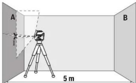
-Ⅱaepdi jkaikbH A ka6bpfaCbHa 6afttan, enuwey KpaabH HnBENPnEh3. Naep cb3bKTapbl Ka6bpFada aKbIi-WuKaBHI HYKTEciHOpTacbiH Benrinej3 (IHyKTci).
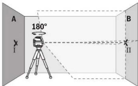
-0nwey KpaBbH 180°6paan, OHbHNBennpen na3ep cb3bKTapbHbH apFB B Ka6bpFacbHdaFb aKbIi-WKyblH HkyTecin 6bnrineH3 (II HkyTci).
-Onuey KypaBbH bypamai B Ka6bipFacbHbH KacbHda KOBbH, KocbH3 da HNBenHeH3.
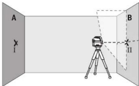
-0nuey KpaabHbH 6nIKTirH (WtATNBTEp Hemece 6ap 6oIca tipeyi iKemerHe) naep cb3bIKTapbiH aNkbluYHKbIHyKTEcB Ka6bIpracbHa andbimEn 6enrIneHRe HkyTeE II cAke6oNaTaHdai 6afttaH3.
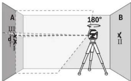
-0nuey KpaBbH 1806ypan 6nKtirih 3eepTneH3. OhA KaBbipacbHaTK naep cb3bFbBenrInreH I HykTeCineH etetIH erin 6afttaH3. Onuey KpaBbH HnBeInpEn, naep cb3bKTapbHbH aKbH-yKbH HykTeCIN A KaBbipacbHaDA (III HykTeCi) bEnrIneH3.
A kabipfacbHdaBIm HeI Eki6eBnireHReH HkyTeHH aHbpMaBbIfBEnwey KypaBbHbHdAn BnIKTKHe aybitkyh Kepcetei.
2×5M=10MenIeeyKaUbIKTbIFbIHdafbpyKcatetireH MaKcMaNdbaytky:
10Mx±0,3MM/M=±3MM.ImeHIIIHYKTeNepi apacbHdaFb daBbPmaaBbIFbE hKe6i 3 MM KpybTnC.
KoIeHeHcIb3bIKTbIH HINBEnHpney dAndiRITekcepy
TeKcepy ywih wam. 5x5 M6oc KeHjcTik KepeK.
-Onuey KypaunbIH A MeH B KabbpFanapbHbH apacbHdaftb optada WtATNBkE Hemece KaTbI Teric 6TeK opHaTbHb3. HBeInpney AYBOMATNkAcbHbH KEMERIMEH KeJNeHeC cb3bIKTBK KyMbIC pexMmTHaHdAn, Onuey KypaunbIH HBeInpneH3.
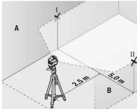
-Onwey KpyanbHaH 2,5M KaabkTbKtKa eki Ka6bpFpa anaepnik cb3bIK optacbi HbenrineH3 (A Ka6bpFacbHda I HYKTE,B Ka6bpFacbHaDIIHYKTE).
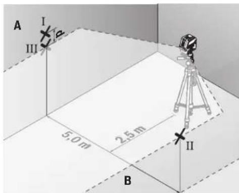
-0nwey kypabih 180°-ka 6pyan 5 m apakaibktbikta ophaibh3 kane HNBennpneHj3.
-0nwey KypaibHbH 6nKtirH (WtaTHB Hemece KaKet 6oNa, tipeiyu Kemerim) na3epniK cb3bK optacbl B
Bosch Power Tools 1609 92A 4HE| (09.08.2018)
168|Kaazak
Ka6bIpaBHa anbH ana 6enrIneHre HHyKTe CKeC 6onatbHdA typanaHb3.
-AkabipfacbHda naepnik cb3bIK optacbi HII hykTe petihebenrineH3 (I hkyteHH yctihHe HeMece actbHa tiriHEn).
Aka6bipfaCbHdaFbEkiBenrIneHReH MeH III HkyTeHi d aHbipMaBbIbFbEOnWey KpaJIbHbH KeJeHeH Cbl3bKTAH DAn aybiTKyBn KepceTei.
2×5M=10MenweyKaWbIKtBfHdaFbypyKcatetireH MaKCHMaNDbayBkY:
10Mx±0,3MM/M=±3MM.ImeHIIIHyKTepeapacbHaFbdaibpmaBbIbFeEHKe6i3 MM Kypaybl Tnic.
Tik cb3bIKTBH HMBENHPney dAndirin TeKcepii3
Tekcepy yuih (kaTbI tabaHa) ecikTH ap xafbiHAn KEMiHne 2,5 M kai gonatbH ecik Teciri Kepek.
-0nwey KypaBih ecik Tecirihen 2,5 M KaawbIKbTKa6ekem Teric TabaHda opHanaactbipbHb3 (UtaTHBE emec). HBeNpIeay ATOmatKacbImEH TIK Cbi3bIKbTKxMybIC peKmIH TaHaHbIa. IaepNIk Cbi3bIKbEciK Tecirihe 6aftTan, Onwey KypaBih HNBenPipeHj3.
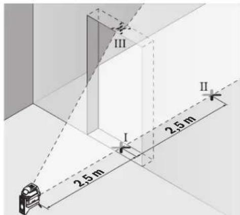
-Tik naeep cb3bfbHbHIOptaBfBcH ecK teciriH eedeHH (I hkyteci), 5 M KaabkTBkTa ecK teciriH6acka XafBHda (II hkyteci) Xane ecK teciriH Kofapfbi WeiHde (III hkyteci) bEnrineH3.
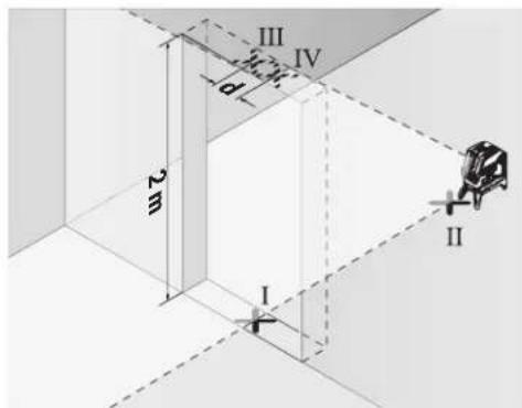
-0nuey KpaBih 1806ypan,ecic Tecirihb6acka XaFbHda tikeen II HkyTecinIH apTBHa opHaTBbI3. Onuey KpaBih HNBEnHpN, tik Naep cb3bIFbH optabfbl HaKtI MeH II HkyTepeH eTeiEtin 6afttaHbI3.
-ⅡaepcblbfbHbHOpTaNbfbHecIK TeciriHINKOFapFbI WetInHe IV Hkyteci peirHe 6enrineH3.
Aka6biprafcbihdafbIII me IV eki 6enrirehen HkyTeHH aibpMaBblbIbEneey KypalbHbH,an 6nKiTikTea btkyih KepceTei.
-Ecik teciriin biiktirih enwehia.
MaKcImaIbI pyKcatetinH aybIKy TeMeHderiJe eneTenei:
ecik tecirih Koc 6niktiri × 0,3MM / M
Mbican:ecik TeciriH2 M6nKiTirHderi MaKcHMaIa byitky
2×2M×±0,3MM/M=±1,2MM.COHdbKtAH III MeH IV HkyTeneepiH apaibfbiEh Ke6i 1,2 MM BoJyBi KepeK.
Heri3ri HkyTe dAndiirin TeKcepy
Tekcepy yuH eH MeH Te6e apacbHaa amameh 5 M uMaacbHdaftb6epik6etteri 6oc enwey xonblbH apakaabTbFlk KaKer 6oanbl.
-0nwey Kypabih 6ypama yctafbikka (13) opHaTbn, eHRe KObIHbI3. HyKTei JxMbc pexmH taHan, enwey Kypabih HnBeInpneH3.
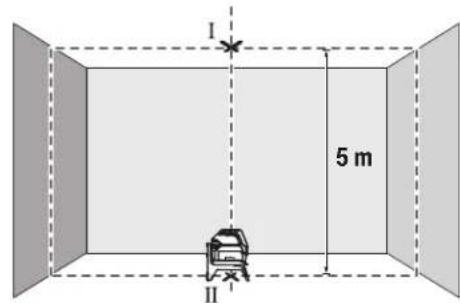
Korapfnnaepnik HkytehiOpTacbiH Te6e(I HkyTe) 6enrinei3.OfAn KocacactbHfbnaepnIK Hkytehi, opTacbiH eede(II HkyTe)6enrinei3.
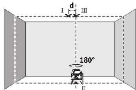
-0nuey KpaBn 180ka 6paHb3. OhTeMeHr I naepnik HkyTeHH opTacblBenrInehre H I hyKteDe 6oNaTbHdA etin opHaNactbipbHb3. Onwey KpaBn HNBenPnEi3. XorapFnaepnik HkyTeHH optacbl (III HkyTe) 6enrIneH3.
Te6eBeBenrInHReI XaHe IITyKTepeDd aBipMaBbNfBbEOnuey KpaBbHbHdAn 6nIKTKTe H ayBtkyBn KepcTei.
MaKcMaIbI pyKcAt etinTih ayBtky TeMeHderiDee
ecentenei:
edeH MeH TeBe apacbHaFb Koc KaBbIKbIK × 0,7MM / M
MbCan: eEH MeH TeBe apacbHaFb KaBbIKbIK 5M
6oNfAHa MaKc. ayBtky KeNeciJeB oNaJIb: 2× 5M× ± 0,7MM / M = ± 7MM CoHbIKaTH MeH III
HYKeTepdIH apanbFbEh Kebi 7 MM 60nbl Kepek.
Painanany HycaynapbI
Benriney yinepaabim TK na3epnik Hkytehi Hemece na3epnik cb3bIKtbIH opTacbiH nainanahB1i3. Na3epnik Hkytehi eniweH mecec naepnik cb3bIKtbH eHI KaawkbTbKneH e3repeDi.
UtaTHBneHxymbcictey (kepek-kaapak)
TATNB TpakbI Xhe 6nKrtiri pettenerih eWey tabaHb1
Bona. The Wey KpaBn 1/4" WTAHB nATPOHBmE (9)
TATNBiHE Hemece (22) cTaNapTTb foTOwTAHBiHE
opHaTBnB3. CTAHapTTb KpybInc WTAHBiHe 6eKity yuH
5/8" WTAHB nATPOHBn (10) naDanaHBnB3. The Wey
KpaBnBH WTAHBTeri KynbINTay 6ypaHdacbIme 6ekitih3.
The Wey KpaBnBH KocydaH aNbIH WTAHTBI 6afbbTaB3.
Omb6an yctafblwnen 6ekitih3 (kepek-kapak) (G cypetih kapaht3
OM6eBn yCTaB118)KemerimEn OJlney KypanBn, MbcAbl, TIK aMakTapda, KybIbpnapa HEmec MaHHTTeTIN MaepnAnJaDpa 6ekITy MyMKH.0M6eBn YCTaB11bTj KHe eJeHik WtATNB petIHne NaIaNahy MYMKH 6oBnE INeWey KypanBnHbN bNIKTIK 6ObHwa 6aftTanyBn OHtaNaHbPaabbl.
Onuwey KypanbH KocyaH aNdbH aM6eBn yCTaFbIHTb (18) Depeke 6afblTahb3.
Ja3ep HbicaHbIK TaKTacbIH naIaIaNHy (MbHa cypETI KapaHbI3:G)
Ja3ep HbIcAHIbIK TaTacB1 (19) KOnaIcbH3 XaFdaJdaXaHe 3aK KaUbIKbTKapDa Ja3ep cb3bIFbIH KePIHcIH KaKaCapTaBl.
Ja3ep HbicaHbIK TaKTabHbIK KaIataPbIH JXapTbcI (19) Ja3ep Cb3bIfHbIK KepiHyIH JxakCapTbIN, MeNIDp XapTbcI apKbIbI Ja3ep Cb3bIFI Ja3ep HbicaHbIK TaKTabHbIH apTbHAn Da KeipHei.
Ja3ep Kepy Ke3inDipiri (KepeK-Japak)
Ja3ep Kepy Ke3inDipiri Kopway JapbIKTbIFbH cy3rinei. Ocbnai Ja3ep KapbIFbKe3 yuHJXapKbIHpaK 6oanaJI.
P3ep Kepy Ke3indipirin Koprahbiu Ke3indipiri petihe naaana6b13. P3ep Kepy Ke3indipiri napecayneicn JaaKcbpaK Kepy yuiH Kbi3MeT Xacaanbl, 6pak onnaep cayncineH Kopraambl.
PaeKepyKeinipirH Kyh Keinipiri petiHne Hemece kon Ko3fAibcihna naDanaHa6b13. PaeKopi Keinipiri ynbtpafoNEt cayenepeHToBik Kopram peH Kepy KaInetIH aazTadbl.
XyMbICMbicanapbl(MbHa cypeTepi kapaHb3:B2-F2,GxheH)
OJUeY KpAaH naJaHaHy MmKInIgTePiH Mbicanapb cypeTep 6etepiHe6epinreH.
OJy KpaBnH aDnBm TKepeiTeH aMak HEmece
Wtke JAKbIKoBn AP eNwyeDeH anDbH HNBENPHej3.
Ja3epNIk CbIbK PnH aMak HEmece WtINH apaNbKTapBH
ApdA bIM Eki biipipieH en y3ak opHaanackaH hYKTenepe
enweH3.
TexHnKaNbIK KyTIm XHe Kbl3MeT
Kb3MeT Kepcety KaHe Ta3anay
Onwey KypaBbTaa3aYcTaHbIa.
Ouwey KpaBnCyHaHEmece BaKa CytbIKTbIKTapra 6aTbpMaHbI3.
NactaHnyapdbcynahf,yMcaKwSybepekencypTih3.
Xyfbu3aTAPdbHeMeceepkIHTepPi naDaanHa6aHb3.
Na3epUbIFBCTeCirIHderiAmaKTapdbCanaNbTa3aAnbH
KblbIKTapfaHaapaydpbHb3.
TytbHybIfa Kbl3Met KOpceTy XHe naJaIaNy KeHecTepi
Kb3met Kepcety we6epxahacbi Ehimdi jkHey kHe KYty, coHdai-ak Kocankbl 6eIweKTeP typaIbl cypaTapFa Xayan 6epei. Kapbiny cb36anapbl MeH Kocankbl 6eIweKTeP typaIbl MmIImeTepIi TEmeHderi MeKeHHaJaTaTabacbla: www.bosch-pt.com
Bosch 6aFapnAmacbKeecTo6bbi3inEhImepXhe OnapHbHepeKek-KapaKTapbITypaBcypaKaTbpHb3raXayan 6epei.
CypakapkoKHeKocajkb6eWKeTpeTancbipbc6epy Ke3HdMeMHTeTTYPpeEHIMDih3aybTTbIK TaKTaWacbHnArb10-caHdbEHHEMPiHJx3bHb3.
HdiPywi taanTapbi MeH HopMaapbIbIH caKtanybIme
3eKtp KypabIn HKeHDey KeHe KeinDi Kbl3MeT KepCteTy
6apBik MemKeTeP ayMaBHaTe K PObepT Boi
PhiMaBk HeMece ABTopn3aunraHFaH Kb3Met KepCteTy
opTaBkTAPdaOpBnDanaBb. ECKEPT! 3aHcb3 XoJImeH
ekINrEh OHIMdpePi naDanaHy Kayinti, deHcaybIbIbH3Fa
3HH KENTpyi MymKiH. OHIMdpePi 3aCb3Xacay XaHe
Tapaty EkIMuINK XHe KeNIMbCTbIK TepTin BoBHnla
3aHMen KydanaHaBbl.
Ka3aKCTAH
TybinybnapraKeHec6epyXaHeWafBmApDkaBnay optanbflb:
"PoBept Boi" (Robert Bosch) KLIJC
AJIMATKI.
Kaazkctah Pecny6nKacb050012
MypatbaebK.180y
"TePmec"50,7kaBAT
Ten.: +7 (727) 331 3100
_aKc: + 7 (727) 2330787
E-Mail: ptka@bosch.com
CepBnCTIK KbI3MeT KepCeTy opTaIbIKTapbl MeH Ka6blJday
170 Romana
nyHKTePiH MeKeH-KaBb TypaBb TonbIK XHe e3eKti aknapaTb Ci3: www.bosch-professional.kz pecm caTTaH ana anacbi3
Kedere kapaTy
Oniwey KpyaBih, OhbiXabkTapbi MeH KantamacbH KopwaraH opTaHbI KOPaHTbH KeJeE XapatyopbHa TancbipyKaKeT.

Knyeuy KpyanapbHn He 6aTapeaepnapy y KOKbcHa TaTamaHbI
TekKaHaEOeNepiyyin:
Eypona 2012/19/EU epexeci bohbuHa jkapamcb3 enwey KypanapbI xHe Eypona 2006/66/EC epexeci bohhuia 3aKbIMdAnfah Hemece ecki akkymnytOp/6atapennap 6eneKHHaBn Kaede JkapatblvkaKkTe.
Româna
Instruetiuni de siguranta

Service sculelectric
Strada Horia Macelariu Nr. 30-34, sector 1
013937 Bucuresti
HomepHaHeTo Ha eneMeHTne ce OTHacdo H3o6paKeHneTo Ha H3MepBaTeHNHa ypeHa cTpaHnIaTa CmrgyPte.
(1)OTBOP3aH3XODJNIAzepenIbY
(2) CbctoHnHe Ha baTepeHnTa
(3) CBeTIINHeH INIINKaTOp 3a pa6Ota 6e3 aBtOMaTHUHO HINBeIIPAhe
(4)Бутон за реким пазерна точka
(5) Bytoh 3a pekHm na3epHa nnHH
(6) Kanak ha nghezdoTo 3a 6aTepeHn
(7)KaHAn3aNo3nUOHHpaHe
(8)Пусковпреквс Bau
(9) The Do 3a MoHTnHaNe KbMaTbN 1/4"
(10) THe3o 3a MoHTnpaHc KbM CTaTHB 5/8"
(11) Cephen Hoomep
(12)Ппс equурдитна tabekenka 3a nazeрни lyb
(13)Bbptaa ce ctoka(RM 1)
(14) HanpaBnaBaanda mHa
(15)HaŋbχeH npncbeHHntenOH oTbOp
(16) MarHHIT
(17) CkO6a 3a TaBaHn
(18) YHINBepcana HcTOnka (BM 1)
(19) Lazerha ueBa nnoka
(20) Kyφap
(21)BnOJka
(22) CtaTHB (BT 150)
(23)TeNeckonmHa uHa (BT 350)
(24)Преедиаэна уанта
(25) La3eprHn ouHa
A) N3o6pa3eHnTe Ha fHypyHte H ONCAHnTe DOblnHTenHn npncnoc6neHn He ca BkLNouHn B cTahdapTha OKOMNEKTOBka Ha ypeHa.3uepnATEHe CNbck H a DoIbHnHTenHn pncnoc6neHn MOXeTe Da HamePte CbOTBEHO B katanora Hn 3a DoIbHnHTenHn pncnoc6neHn.
TexHHueckn daHHN
Toykob mnnnne nnanepe npd GCL 2-15 GCL 2-15 G
| Каталожен Homep | 3601K66E..3601K66J.. | |
| РавOTHA зона1) | ||
| - Пазерна линь 15 M 15 M | ||
| - Пазерна точka harope 10 M 10 M | ||
| - Пазерна точka надиу 10 M 10 M | ||
| Точноct на Новелега | ||
| - Пазерни линь ±0,3 MM/M ±0,3 MM/M | ||
| - Пазерни точи ±0,7 MM/M ±0,7 MM/M | ||
| Дианалазон на豌оматуно Новелега- He, Тлиунho | ±4° ±4° | |
| В体现在 за豌оматуно Новелега, Тлиунho | <4 cek | <4 cek |
| РавOTHA Temпегатура -10°C...+50°C -10°C...+50°C | ||
| Temпегатурахдлалазон за сбхсан- Ване | -20°C...+70°C | -20°C...+70°C |
| макс. равOTна височи над базова- Та Височиа | 2000 M | 2000 M |
| Отосятелна влажноct макс. | 90 % | 90 % |
| Стосян на заимрсявае сблесно IEC 61010-1 | 2B) | 2B) |
| Клас пазер | 2 | 2 |
| Пазерна линь | ||
| - Тли пазер | 630-650 nm, <1 mW | 500-540 nm, <10 mW |
| - Сcentян на пазерни лыч | чeredвени | Зelenно |
| - C5 | 1 | 10 |
| - Д�� comprетця | 0,5 mrad (плень bгел) | 50 × 10 mrad (плень bгел) |
| Пазерна точka | ||
Bosch Power Tools
1609924HE|09.08.2018
180|Блгарский
TooyoN nnHeeH na3epen ypeGCL 2-15 GCL 2-15 G
| -Tin lazaep 630-650 nm, <1 mW 630-650 nm, <1 mW | ||
| -Zbary ha lazaerHia ly cheBeno cheBeno | ||
| -Cs | 1 | 1 |
| -DiBnprreHua 0,8 mrad (nIaHbIa) 0,8 mrad (nIaHbIa) | ||
| ΓHezdo 3a MoTHnPaahe KbM cTaHB 1/4", 5/8" 1/4", 5/8" | ||
| BaTePm 3 × 1,5 V LR6 (AA) 3 × 1,5 V LR6 (AA) | ||
| ΠροβλιχητεLHOCT Ha paδθa B pexHm | ||
| -PexHm KpbCTocAHn LInHH n TouKa 6 q | 6 q | |
| -PexHm KpbCTocAHn LInHH | 8 q | 8 q |
| -PexHm LInHH n TouKa | 12 q 10 q | |
| -PexHm LInHH | 16 q 12 q | |
| -PexHm TouKa | 22 q 22 q | |
| Maça cIbIaIacHo EPTA-Procedure 01:2014 | 0,49 Kr | 0,49 Kr |
| Pa3MeRi (ДылЖина × Ширпа × Височиа) | ||
| -6e3 BvptHsa ce StOJka | 112 × 55 × 106 MM | 112 × 55 × 106 MM |
| -c BvptHsa ce StOJka | 132 × 81 × 163 MM | 132 × 81 × 163 MM |
| Вид зaцита | IP 54 (Зaцитен срешу прах и ВODH nрьск) | IP 54 (Зaцитен срешу прах и ВODH nрьск) |
A)Пи He6nIaropnIaTHN yCIOBnH (HAnp. HEnOncpeIcTBeHH CbHueBn IbHn) pa6oTHnAT mHaIa3oH MoKeJa e no-MaIbK.
B) Hma cmo HnpoBODHMO 3aMpbCBAHe, npH KOeTo o6aue e Bb3MOXHO Da ce OauKBa BpeMeHHo pNpuHNHe HPOBODMOCT NopdN KOHDeH.
3a eHNO hIeHTnHcHpaH He BaIHH 3MepBaTeH en ypeD cnyxH cepHHN HOMep (11) Ha TaBeHKata Ha ypeA.
MOnTnpaHc
H3non3BaHe/cmHa Ha 6aTePnnte
3a3axpaHbAHe Ha 3MepBaTeHHy ypeI ce npenOpbBa H3- non3BaHeTo Ha aKaiHO-MaHraHOb6aTePNH.
OTbOpTe KaNakaHa rHe3dTo 3a 6aTePn (6) nocTabete 6aTePn.
BHHMabaiTe 3a npabHnHata NM nonpHocT, H3o6pa3eHa Ha ΦHypata OT bBTpeuHata CTpHa HA THe3Dto 3a 6atePmH. Ako 6atePHTte CTAHAT Cna6n, HNDHKATOpbT 3a 6atePmH (2) 3anoYBa DA MIRFa cBc 3eNeHa CBETnHa. OCBEN TOBA Na3epH HNTe NHHM MHrAT Ha BCEK 10 min 3a npHbN. 5 s. OT hauJATO Ha MIRHaHTo H3MePbATEHnHrT ypeD MoKeJa pa6Otn Oue npHbN. 1 h. Korato 6atePHTte CHe3OuT, HenoCpeDc TBHeO pPeDN ABTOMaTHO H3KnIOuHa He H3MePbATEH Hnry UpeD Na3epHtne LHHM MHrAT OTHOBO.
3aMeHnTE BnHaBn BCnK6bATEHN eNDOBpeMeHHO. H3non3BaTe BnHaBn 6aTEPNOT eHN n CbU pOn3BOIeN n c eHnKaNaNTeT.
Ako npoBnKTeHNO BpeMe HMa da N3noN3BaTe ypeDa, N3BaXaJaTe 6atePnnte O Hero. Pnp npOblnxKTeH NO cbxpaHbAne B Heer 6atePnnte Moar Da KopoOpnP aT Na da ce camopapdEaT.
Pa6ota c Bbptnata ce ctoika RM1 (Bx. qnr. A1-A3)
C NOMOHTa Ha BbPTAAca ce cToiKa (13) MoKTe Da 3aBbP TaTe H3MepBaTeHNH ypeHa 360° OKoN OeHTpAnHa, BnHa
H BnIMa OTBeCn TaOka.Taka na3ePHNte NHHMORat Da 6bDat No3NIOHOHPaHn ToH0,6e3 da 6bJe npOMeHrHa No3N ⅢIHTA Ha H3MEpBaTeHNHype.
IocTaBeTe H3MepBaTeHnH ypeD C BoeUa KaHaN (7) Bbp-xy HappaBnBaAuta WnHa (14) Ha BbptaaTc Ce cToiKa (13) nBkapaTe H3MepBaTeHnH ypeD do ynp B pnt-phiopmata.
3a demontnpahe n3dbpnaTe n3MepeTnHnypeDOTBpTHaTaCeCTOHa BnpoTHBOIOnOKNHPOCOKA.
Bb3MOKHOCTn 3aNo3NIOHINpHaNe Ha BbPTAata Ce cTOnKa:
- NoCTaBeHa Bbpxy paHbNoBbpxHOCT,
-3aXBaHaTc BnHTOBe KbM BepTHKaHAnHa NObbpxHOCT.
-BKOMBnHaCnCbCKo6aTa3aTabAHN(17)KbM MetaHn NaCHHaTbAHN,
C NOMOHTa Ha MaHHTnTe (16) KbM MetaJIHN NOBbpxHOC-TH.
Pa6ota
IyckaneBekcnoaatauia
Pepna3BaTe H3MepeBatenHH npH6OpOTOBnaxHaBaHe HnpEeTHo NpdaHae Ha CbHueBn b4H.
He n3naraIte H3MepBaTeHnHyaypeHaekCTpeMHN TempepaTpyHnHpe3KNtempepaTpyHnpomeHH.
Hanp. He ro octabTne npOdbJNKHTeNo BpeMe BAOTOMoBnI. Pnro TOnEMN TempePaTyPhn pa3NknocTabaTe enekTpOHCTpyMeHTbT nbPBo Da Ce TmpeHpa npeDn da
1609 92A 4HE | (09.08.2018) Bosch Power Tools
roBkIOUHTe.IpHekCTpeMHNTempeaTyprnHINrOEmTeMmepaTpyHnPa3NknToHocTaHaH3MePbTeHHypeMOKeJaCeBLOHn.
1368baTe CnHH yapn Hn H3nyckaHae Ha 3MepeBaTeHHype. Cneu yapHN Bb3eJeCTBn Bbpxy 3MepeBaTeHHypeTpr6Ba Da n3BbPwBe IPOBepKa Ha ToHocTa My, IpEdu PaNpOdbNkHTe Da rno3No3BaTe (BX. "IPOBepKa 3a ToHocHa 3MepeBaTeHHnHcTpyment", CtpaHnca 183).
Korato npenacate ypeda, npedapntenho ro n3knouBaiTe. PnnpN3knOuBaHe moynbTa Kone6aTeHNn DInHKeHHe Ce 3actoOpRa, Tb KaTo npn CINn Bn6paunMoKe da 6bDe nobpehen.
BkIIOUbaHe Hn3KIOUbaHe
3a BkIOuBaHa Ha 3mePbaTeHHypeI npMeCTe Te NycKoBn npKeBcBaU (8)do No3HuaTAt "n" (3a pa60ta 6e3 abTOMATNUHO HNBENPAHe) nn do no3HuaTAt "n" (3a pa60ta cABtOMaTHNO HNBENPAHe).BegHara cnEg BkIOuBaHe 3mePbaTeHHypeI n3bYBa na3epHn IbCh npEe 3OTBOpHTe (1).
He hacoubaTe na3epHHa bky KbM Xopa HnH XNBOTHn; He rneJaTe Cpeu y na3epHHa bY, cbO n OT roJAMo pa3cTOnHne.
3aH3KIOUbaHe Ha H3MepeBateHNHpye npemeCTe Tyc-KOBnI pKeBcBaay (8) B No3Nua "Off".Pnp H3KIOUbaHe Mo-ynbT 3a Kone6aTeHNHTe DnBxKeHHce 6NoKnpa.
He octabnte ypea Bknouenb63 n330p; cne KaTo npKIOUHTe paOba, ro H3KnOuBaHre. Dpyrnnnca Mo- rata 6bdatacnenenOH naepnnaIb4.
Pn npemHnHaBe Ha MaKcHmAlNo DoynctHMaTa TEmnpaTy pa ot 50CypeBt Ce n3KnIOuBa 3a npednaBaHe Na naepHHN HIOI. CneOxJaDaHe N3MepeBaTeHNrYPeE oTHOBOTOB 3pa6oTa HMOKe Da 6bJe BKNIOUeH.
ABTOMaTHUHO N3KJIIOUBAHe
Ako 3a npH6n.120 MHHyTn He 6bIe HaTHcHAT 6yToH Ha n3-MepBaTeHNHpyE,3a npEJa3BaHe Ha 6bATENHTe3MEpBATeHNHtypeC H3KIIHOBA ABTOMaTHHO.
3aДаВКИQUHTe NOBTOPO N3MepBaTeHINHуpeI CneI abTOMaTHUHO N3KIIIOVAHe,MOXeTe Da N36byTaTe NyCKOBINppe
KbCBaY (8) NpBO Ha No3uNn "Off" H CneT TOBA OTHOBO Da BKNIOHTe N3MepBaTeHNH YApeD HnHa HATNCHeTe 6yToHA 3a peKHM Ha pa6oTa Na3epHa TouKa (4) HnH 6yToHa 3a peKHM Ha pa6oTa Na3epHa HnHn (5).
BpeMeHHo DeaKTbHpaHe Ha aBTOMaTHHOTO 3KJIIOuBaHe
3a daeakTNBnPaTe aBTOMaTHUHOTo N3KJIOUBaHe,HaTNCHe T 3aepbXKe Tne 3 cekyHn6byTOHa 3peXHM Ha pa6oTa Ia3epHa IINHn (5) (pnp BkIOuEH HmEpBaTeEN ypeI).
PnIeAekTHBnPaHe Ha aBTOMaTHuHOTo N3KJIQUBaHe Na3epHHTe HHHnn PpIMnBt KaTko 3a NotBbpxDeHne.
Yka3aHHe: Ako pa6oTHaTa TempepaTpya HAnxBbpnn 45°C, aBTOMaTuHOTOn 3KIOUba He MoKe Ja 6bJe daekTbNpaHO.
3a da aKTHBnPaTe aBTOMaTHUHOTo H3KNIOuBaHe, H3KNIOUeTe HOTHOBO BKNIOUeTe N3MEpBaTeHnHrypeD.
№60 npa pexma ha pa60ta
Ja3epHHrIypeIpa3nOraC HKOJIko pa60THPaBHHH, MEKdy KOHTo MOKeTe Da IpEKBKIOUbATE NO BCaKO BpeMe:
-PeKHM Ha KpbCTOCAHN HNNH N TOUka: H3MepBaTeHN HnT ypeI reHePnpa eHa XOpN3OHaH n eHa BepTKaHn Hna3epHn HnHn HnpeD, KaKTo n No eHa na3epHn TouKa Harope n HADony. Na3epHnTe HnHn Ce npecuat noB bTbn 90°
-PexnXoxH3OHTaHa HHHN:H3MePbTeHNrTypeIeHepnpa edHa xopH3OHTaHa Ia3epHa HNNH HAnpei.
-PexHM BepTKKaHnHa HnnHn: H3MepBaTeHHnT ypeI reHeepnpa eHa BepTKaHa Na3eepHa HnHn HaIpeI. Pn noCTaBHe Ha n3MePbATEHHnY ypeI Ha TabHa BepTKaHnHa Ta3eepHa NnHn Ce IINbVbA npE3 roPha Ia3eepHa TOka.
NocTabaHHe Ha N3MepBaTeHNnHa ypeH HenOpcePeCTBeHo HA CTeHa BepTnKaIhata Na3epHa NINnReHepHp eHa noTH 3aTBopeHa O6KnOHa Na3epHa NINn (360°nnn).
-PexmToKa: n3MepBaTeHnT ypeI rHeHpHa no eHa ToKa HaroPe HADONY.
BcnKnpeKHMOCBeHpeKmTOKaMOraDaHbDat H3non-3BaHHKAkToC,taKaN6e3ABOTMATuHOHNBEInpHaHe.
Pa60ta CbC ChTeMaT3a ABToMaTHUHO HNBenHpaHe
| Последовател noct ha paşobtнite CTbπκn | Peximхор- ЗоHTанha li- нna | PeximВерт- Калнha li- нna | PeximTOчka CBetltneHиdu- Катор за paşobta бez abTomatуно нвениpane (3) | Фигра |
| Пусков пекьсвач (8) в поэцяя " " | ● ● ● | B1 | ||
| Рexim Крьстocану li- нни | ||||
| + | Hatsche 1×6bytoHa 3a peşим ha pajobа пазерна li- ння (5) | ● - ● | C1 | |
| Hatsche 2×6bytoHa 3a peşим ha pajobа пазерна li- ння (5) | - ● ● | D1 | ||
| Hatsche 3×6bytoHa 3a peşим ha pajobа пазерна li- ння (5) | - - ● | E1 |
Bosch Power Tools 1609 92A4HE (09.08.2018)
182|Бьлгарскn
IpoBepka 3a ToUHOCT Ha H3MepBaTeHnHnHCTpymENT
ФakTOpH, BnHHeuH Na ToUHOCTTa
HaI-rotIaMo BnHHe BbPxy ToUHocTt HMa OKoIHATA TeMnePaTpya.CneuaHIO TemepaTpyhata pa3Nka OT nOda Harpe MoKe Da npedn3BnKa OTKIoHEHnHa Ia3epHnIb4.
TbkyrpaHEnbHTHaTeMnepaTypabaB6N3OCTnoNoa e Ha-nrA,NO Bb3MOXHOCT Tp8Ba Da MOHTnpate ypeHa CTATNB Hda rnoocTaBte CpeData Ha pa6oTHata NObpxHOCT.
Hape C BbHHTe PaKTOp, npuHa 3a OTKIOHeHHa Morat da bBdAT cbIo n PaKTOp, CbP3aHn Cypea (HaNP. NaAne Hnn CNHn BVbpaun/yyapn). 3aTOBa BNHar npEpi 3anOuBaHe Ha pa6ota npoBepRaTe ToHocTt Ha HNBenipahe.
BnHnPbPO npOBepBaIte ToOHocTHa HnBCOHNHATA Ha HnBENIPAHe HA XOpN3OHTaHHTa Na3ePHa NINH,CNE TOBA TOHOCCTHa HnBENIPAHe HA BEPTKACJHATA Na3ePHa NINH.
AOKPnHRAKOROTNPOBePKITEH3MePBaTeHNHTypeHAnxBpNIMAKCMAMHOIOnyCTHMOTOOTKNOHEHNE,TOITPb6BaDa6bdepeMOHTnpAHBOTOPN3pAHcePB33aeneKTPOINCTpymENTHaBOW.
IpoBepKaHaTOUHOCTTaHbBCOHNaHa XOpH30HTANHATA NHHN
3a npOBepkata Tp6Ba da hMaTe CBO6OHa 30Ha 3a n3MepeBaHe cTbPda OCHOBa CdbJHKHa 5 m MeKdy DBe CteHn A B.
-MoHTnpaIte H3MepBateHIny ypeI 6n3o Do CTeHata A ha CTaTHB INI rnoocTaBeTe Bbpxy TBbpda paBHn NOBbPxHOCT. BKIOUcTe H3MepBateHIny ypeI. N3bepTe peKHM Ha KpbCTOCAHN HINHH CABTOMaTHNO HNBEPHaHe.
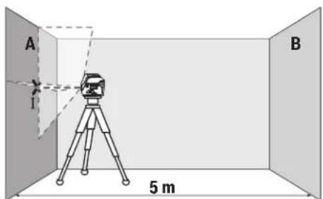
-HacoueI na3epa KbM 6bn3kata cTeHa A I ro n3uKaIte da ce HnBEnipa. MapKnpaiTe cpeIaHa npceeuHata TOka Ha DBete na3epHn nnHH (TOka I).
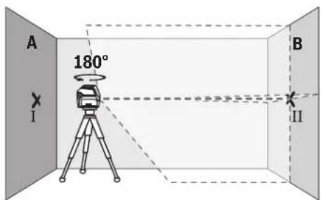
-3aBbpteteH3MepBaTeJHHypeHa180°,H3uKaaiTe rO Da Ce HNBEnIpa ABToMaTHUHO N MapKnpaIte NpeceHuata Toka HaDbete Na3epHNn IHHN Bbpxy cTeHaTBA (TuKa II).
-NotabeteH3MepBateHHypeI -6e3 da ro Bbptite -6n3o do ctehata B, BKIOUeTe ro n ro octabeTae da ce HnBeNpa.
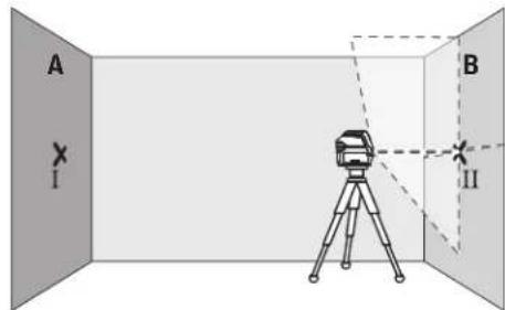
I3MeTe I3MepBaTeHnHa ypeo BnCOnHnA (ye3 cTaTHBa Hn Pn HnoeOxOAnMoCT C nOJaNaHe), Taka ye npeCeHATA TOkHa Ha na3epHNte byn Da nona TaTOHO Bbpxy MapKnpaHata npEn ToBa TOKa II Ha cTeHata B.
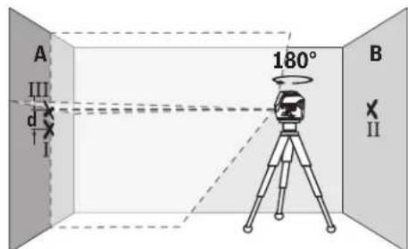
-3aBbpteteH3mepBaTeHnHna ypeHa 180°,6e3 da npomeHnTe BncoyHATA.HacouteTo KbM cTeHata A Taka,ueBepTKaHATA Na3epHa NInHnA da IpemHHaba npe3MapKHPaHaTnpeHnTOBA TOKa I.N3uKaHte H3MePbTaENHnT ypeD a Ce HNBEnHpaN MapKnpaTe ppeceHata ToKaHa Na3epHNTe NbHn HA cTeHata A (TOka III).
-PaJIHKATA d MEXKdy DBeTe MapKnpaHn TOckn I n III Ha CteHaT A daBa DeHcTBNTeHOTo OTKIOHeHne NO BnCOUHNHa H3MEpBaTeJINH YApeI.
Ha pa3cTOrHHe oT 2 × 5 m = 10 m MaKCHMaJIHO DoNycTHMoTO OTKIOHEHHe e:
10m×±0,3mm/m=±3mm.CnepoBateHpo paaHnkata d meKdy touKHe I I ITPa6Ba da e Hau-MHoro 3 mm.
PpOBePKa HtOuHocTtHa HnBEnHpAe Ha XOpN30HTaIIHATA JHHM
3a npoBepkata ce hyxdaete ot cbo60Ha nlou ot npn6n. 5x5m.
-MoHTnpaTe H3MepBaTeHnHpyeB CpeDataMeKdy CteHnTEA B Bbpyx CTaTHN HnIro NoCTaBe Tbpyx 3papaBbHa OCHOBa. N36peTe pexHM XOpH3OHTaJIHa NnHnC aBTOMaTHHO HnBeHnpaHe HnBeHnpaTe H3MepBaTeHnHpyeD.
184|Блларскn
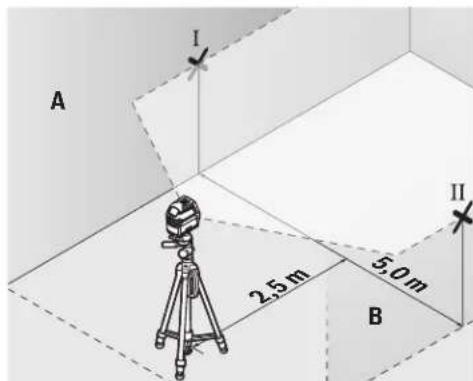
-MapKpaIte cpeData ha Ia3epHata IHHHa DBeTe CteHN Ha pa3ToHHe OI na3epHn ypeD no 2,5 m (TouKa I HaCTeHa A I TOcA II Ha CTeHa B).

-3aBbpte H3mepBaTeHnHa ype Ha 180°,noctabeTo ha pa3cTOnHHe 5 m H3uKaAte Da ce HnBeInpa.
-ИЗмстete ИзмерВателпурд no Всочнa (урe3 стТиБа ИП npH HeOBxOДМСОТ c ПОДагА),ТаKa Ye CpeДATA Ha Na3ePHH NbU DA NOПАНDE TOHOb Bbpy МарКИРаHata npeDnTOBa TOTka II Ha CTehaTBA.
-MapKnpaTe Ha cTeHaTa A cpeTaHa Na3epHaTa NHHN KaTO TOka III (TOUHOHAD,pecn. NOI TOkaI).
-Pa3nKata dMeKdy DBeTe MapKnpaHn TouKn I n III Ha CteHata A daBa JeCTBnteHTo OTKIOHeHne Ha H3MepBaTeHNHa ypeD OT BODopABHaTaNHHN.
Ha pa3ctoHne ot 2 × 5 m = 10 m MaKcMaHIO dOyCTmoTO OTKHOHe Hne e:
10m×±0,3mm/m=±3mm.CnepoBateHno pa3nKata d Mekdy Touknte I H III Tpa6Ba da e HaH-MHOro 3 mm.
PpOBepKa HA ToUHocTtHa HnBEnHpAe BbB BeptHKaHnHO HAnpaBneHne
3a npOBepkata ce hyxdaete ot OTbOp Ha Bpata, pni KOrTO (Bbpy Tbbpda OCHOba) HMa Hai-Malko nO 2,5 m CBO6oHa nIOU OT DBeTE CTpaHn.
-Noctabete H3mepBateHnHnypeHa pa3cTOnHne 2,5 m otOBopa Ha BpataHa TBbpda,paBHObOHA He Ha cTaTHB).N36epete pexHM Ha BEptHKaHnHnHnC aBTOMaTHUHO HnBeHnpaHe.Hacoyete Na3epHATAHnHnKbM Bpa
Tata H3yaKaIe T3MepBaTeHnHrT ypeI da ce HnBeHnpa ABtOMaTHUHO.

-MapKnpaIte cpeDataHa BepTNKaHnata Na3ePha HnHnHa noda Ha OTbopa Ha Bpatata (TOka I), Ha pa3CTOnHne 5 OT dpyrata CTpaHa HA OTbopa Ha Bpatata (TOka II), KaTTo Hn Ha rOpHnPa6 Ha OTbopa Ha Bpatata (TOka III).
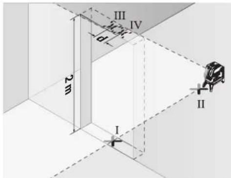
-3aBbptTe H3MepBaTeHnHryeHa Ha 180° n ro nocTabete OT DpyrTaCTpaHa Ha OTBopa 3a BpTa HEnOcePeCTBeHO 3aTouKa II. N3uakaIte H3MepBaTeHnHryePa Da Ce HNBeInpa H hAcOyete BePHTkAHHata Na3epHa HnHHra TaKa, Ye CpeDATA Da MHHaba PpeToKITe I II.
-OTbeneXeTe CpeTata Ha IaaepHata IHHa Hr oPnHa p6 HA OTbopa 3a Bpata KATO TOKa IV.
-Pa3nKaTa dMeKny DBeTe MapKnpaHn TocKn IIV daBa DeIcTBnTeHnOTo OTKnOHeHne NO BnCOUHa Ha n3MepBaTeHHypei.
-ИЗмерете Вионинота Ha OTbopa Ha BpataTа.
MaKcImaHNO DOnyCTHMOTO OTKIOHeHHeMOKeTe Da H3uHcNHTeNo CnEHNHaHIN:
BbTa BnCOUHaTa Ha BpaTata × 0,3mm / m PnMep: PnBnCOUHa Ha BpaTata ot 2 m MaKcHMaHOTO
OTKnHOHeHMe MoKe Da 6bJe
2× 2m× ± 0,3mm / m = ± 1,2mm .CnEIOBATEHNO TOUKKTe III IV MOKeJa ca ha pa3cTOnHne edHa OT dpyra HaMHORO 1,2 mm.
PpOBepKa Ha ToUHocTHa OTBeca
3a npOBepkata CE HyKdaeTe O CBO6OHa 30Ha 3a H3MePbAHe BbpxY TBpda OCHOBA C pa3cTOnHne Mekny IOna N TabaHa np6n.5 m.
MoHTnpaTe N3MepBaTeNnHpyeKnBbMpTaCaTa Ce cToKa(13) HroNoCTabete Ha NoJa. N3BepeTe TouKOB peKHM N3uKaAte aBTOMaTHHOTo HHBenPaHa H3-MepBaTeNnHpyeI.

-MapKnpaTe ceENTbpa Ha rOpHata Na3epHa TOnKa Ha TabaHa (ToKa I).MapKnpaTe cbIo TaKa Ha Noda cEHTbpa Ha DOnHATA Na3epHa ToKa (ToKa II).

-3aBbpteteH3MepBaTeHnHa ypeHa 180°.POnsnoHpaIteToTaka,ueeHTbpbTHaDOnHataNa3epHaTOkaJa eToHO BbpxyMapKnpaHATA TOkaII.N3uKaAteABtOMaTHHOTo HnBeHnPaeHa H3MepBaTeHnHa ype.MapKnpaIteeHTbpaHa rOPhaTaNa3epHaTOka(TOka III).
-PaJIHKaT a dMeKJy DBeTe MapKHPaHn ToQKn I n III Ha TaBAHa DaBa DeHCTBnTeHOTo OTKnOHeHne NO BnCOUHa HaN3MEpBaTeHnYpeI.
MaKcHMaIHO DOyCTHMOT OTKIOHeHHeMOKeTe Da H3uCnH-Te NO CNEHNHaUHH:
DBOHOTOPa3cTOnHMeKJyN0aNtBaHa×0,7mm/m. PnHmep:PnPa3cTOnHMeKJyN0aNtBaHaOT5MaK-CMAMHOTOTKNOHEHMeOKeJa6bJe
2× 5m× ± 0,7mm / m = ± 7mm .CneobateHTockhte I n III moKe da ca ha pa3ctoHHe eHa ot npyra haN-MHO 7 mm.
Yka3aHn3a pa60Ta
BHHaHm MapKnpaTe ceHbpa Ha na3epHaTa TOnKa, pecn. Ha na3epHaTa HHH. C pa3ctOHNeto rOlenMaHaTa Ha na3epHaTa ToKa, pecn. Ha na3epHaTa HHHc Ce npomehr.
Pa6oTa cbc tcaTbN (pnpHaIeXhoCT)
H3noI3BaHeTo HA cTaNbOChrypRa cTa6nH0,peRynpyeMoNo BnCOuHa MOHTnPaHe Ha H3MePbATEHNrY ypeD. NocTabeTe H3MePbATEENrY ypeD c 1/4" NoCTABKaTa 3a cTaNb (9)BbpynpncBcEHHTEJINHBA BNHT Ha cTaNb (22)nnHa oBKnHOBeH TPNHOKHK 3a fOtoanapat. 3a MoHTnPaHeTo KbM cTAHApTeH CPOTNeH TPNHOKHK H3noI3BaTe 5/8" NOCTABKaTa 3a cTaNb (10). 3aterHete H3MePbATEENrY ypeD C BNHT Ha cTaNb.
IpeHn Da BkIOUHTe H3MepBaTeJIHHa ypei, Hacooye CTaHBA rpy6o.
MoHTnpaHe cyHHBepcaJIHATA cToIka (npHHaIeKHOCT) (BXXTe pHr.G)
C nOmoTHa Ha yHnBepcAhnHa cToKa (18) MoKTe Da 3axBaaata He3MepBaTeHNHa yPeD Happ. KbM BepTknAHN NOBbPxHocTH, TpbH NnHn HamaHHeTHNpaUe Ce MaTePnaHn. YHnBepcAhnHa cToKa e NpXoJaCa cbIo TaKa H 3a NoCTaBHe Ha npda H obNeKauBa HacToPoBaNHeTo NBOcOnHa Ha H3-MepBaTeHNHa yPeD.
H3paBHeTe yHHepeCaHaTa CToKa (18) rpy6o, npedn da BkIOuHTe H3MePbATEHNHrypeD.
Pa6ota c n3aephata MeHrTeHa IIIOa (Bx. fHr. G)
Ia3epHATA MEPHTeHa IIOUa (19)noo6pRa BuaHMOCTa Ha na3epHnA bU npH He6NaoropnraTH paOthn ycNoBn H no-tOleMn pAcToHn.
OtpaBaataNoOBHnHaNa3epHaTaMepTeHnIIOUa (19)noo6pRaBnDmmoCTHaNa3epHATAINHHa npe3 np03paHATA NoOBHnHaNa3epHaTALHHMOKe Da ce BNDnOTobpathaCTpHaHa Na3epHATA MepTeHnIIOua.
OuHa 3a Ha6nDaaHe Ha na3epHnaIbU (npHnAaNexKHOCT)
Ounata 3a Ha6nDabaHe Ha na3epHna Nb qnnTpnpat OKoHnata CBetnHa. TaKa na3epHnT nbCtBa no-Necho pa3nHM.
He nnon3BaHte naepnhte ouHa KaTo 3aunTHn OuHa. Naepnhte ouHa cnlykaT aNo-do6po pa3no3HaBaHe Ha naepnHna b? Te He npedna3BAT o NaepHo IbueHne.
He n3non3baTne Ia3epHnTe Ounna KaTo CbHuYeBN ouHnna nn npn WoOPhipe. Na3epHnTe OUnna He npedlarat nbHa UV 3auNTa HamaJIaBt Bb3npHemaHTo Ha CBETOBETe.
Pa6oTHn npHmepn(BK. qHr.B2-F2,GnH)
PnHmepn3a npinoKeHHeTo Ha n3MepeBaTeHNH ypeD MoKeTe Da BnHTe Ha cTpaHncaTa CfHypTe.
BnHaH NoCTaBraIte H3MePbAteHNH ypeI 6bn3o Do nOBbpxHOCTTa HIN p6ba, KONTO Tp8Ba Da 6bDat npOBepBaHn, INnpEn 3aNoUcBAHe Ha BCaKO H3MePbAhe H3uKaBATe Da 3a-BbpNn ABtOMaTHOTo HnBeHnPaHe.
H3MepBaIte pa3ctoHHaTe MeKdy IaeePHn IbU HOBpxHOCT HIN Pb6 BnHaHn B DBe TOcKN, NO Bb3MOxHOCT MaKCHMaIIHO OTdaneEHn eHa O Tpyra.
PpKaHe n cepBn3
Iopdbpkahe n nouchTaBHe
PpKaiTe H3MePbATEHnY ypeBnHaHn YnCT.
He notonraBae H3MepBaTeHNHa ypeD BbB BOa HnIpyrN TeuHOCTN.
N36bpcBaIte 3aMbpcBaHnIa Tc MeKa,NeKo HablaJxHeHa Kbpna.He n3noI3BaIte NoCCTBaun npenapatnn pa3T BOpHTeIN.
PouHCTBaHTe peDOBHO CNEUAnHIO NOBbPxHOCTte Ha H3xoDaHa NaIa3epnHnIbY HBNMaBaHTe Ha He OCTaBt BNaCINKn.
KIneHTcKa Cnyk6a H KOHCyIaHr OTHoCHO ynotpe6ata
CepBn3bT 0e OTROBOpn Ha BbnpocHe Bn OTHOCHO pemOHn H noDpBkKa Ha 3aKynHeHn O Bac npOykt, KaKTo n OTHo pe3epBn qactn. POKOMNoHEThn UeptExn N INHfOpMa- 3a pe3epBnTe qactn 0e OKPne Tn Ha: www.bosch- pt.com
EkmbT no KOHCyNTaHc OTHOC yHnOpeBaHa Bosch ue Bn NOMORHe c yDIOBONCTBHe npu Bbnpocn 3a HauHnte npoDyKTHn TExHNte akcecoapn.
MOnI, npn Bbnpocn n npn npopbUbaHe Ha pe3epBHN qactH BnHaN NocOuBaTe 10-uaPpeHH KaTALoXeH HOMep, H3nncaH Ha Ta6enKaTa Ha ypea.
Былгаян
Robert Bosch SRL
Service scule electric
Strada Horia Macelariu Nr. 30-34, sector 1
013937 Bucuresti, Romania
TeN.:+359(0)70013667(BbIrapckn)
ΦaKc: +40 212 331 313
Email: BoschServiceCenterBG@ro.bosch.com
www.bosch-pt.com/bg/bg/
Бракувае
I3MePBeHHTypeD,IOBbHHTeHHTe npCnOc6HeHH onaKOBKeTep8BaJa 6bDaT NOJIOxHeH Ha ekOJIOnuHa npepaBoTa Ka yCbBaBaHe Ha CbDbpKaUte Ce B TxA cypoBHN.

He 3XbPnIe H3MepeBatenHte ypeN n 6aTe- pHnTE npn 6nTOBnE OTnabu!
Cama 3a ctpaHH ot EC:
Cbrrnaccho eBponeNcKa dHpeKTHBa 2012/19/EC m3mepBaTeHNHTyeN, KOITHO ME MOrAT da CE non3Ba NOBeue, a cbIaCHO eBpOneNcKa dHpeKTHBa 2006/66/EO NOBpeEN HINX3xaEBHe OHKnHOBeHn HnA kymyNaTOpHn bATEPHn TpRABa Da ce Cb6bpat npeDaba 3a onON3OTBOPBAHe Ha cbDbPxAuNTte Ce TBx CypOBHN.
MaKeDoHcKn
Be36eHocn HaONMeHN

CnTe yntcTaTpe6a Da Ce npouHTaAT n da ce BHHMABA Ha HMB, 3a Da MOKe 6e36eHNO 6e3 onaCHOCT Da pa6oHTe Co MEPHNOType. DOKONky MEPHOType He ce
KOpHCTn coTnacHo npHNOxEHNe HNcTpkyuH, MoKe da ce HApuyn FyHKnjuTa Ha BrpaJeHNTe 3aunTHn MExAHmB OMePHNOT ype. He rN oWtetyBaJte HaneHHnTe 3a npeynpeyBaHe. IOBPO UYBAJTE rN OBHE YNATCTBA H PEPDAETE rN 3AEHO CO MEPHNOT yPeI.
BHHMaHHe -doKoKny KOpNCTHe dpyrHypeHn 3a nOdecyBaBe H paKyBaBe oCBe HOBe HABeDEHTe HNNONHaKBN NocTAnKn, OBA MoKe Da DOBeDe Do onaCha H3NoXeHoCT Ha 3paYeBe.
Mepnnotypecencnpaayba co haneHHua 3a npdeynpeybaiee (03naueho Ha npHKa3oHa MEPnnotypeHa rpaHnKata cTpana).
Dokonky TeKCTOT Ha HanelnHuaTa 3a npdynpyBaBe He e Ha BaHOT ja3NK, Bp3 Hero 3anene Ta ha HanelnHuaHa BaHOT ja3NK nped npbata ynotpe6a.

He ro hacooybajte nacepckn0t 3paK KOHnlaa nn KBNOTn HEmoJTe N Bne camnte da rnaTe BO dpeKTHNOI nppeKnTnpauKnot nacepckn 3paK. Taka
MOKe Da IIN 3acIeNITe NInaTAt, Da InpEn3BnKate HecpeKn INN Da IIN OOTETNE OHTE.
Dokonky nacepcknoT 3paK Docnee O ouHTe, BeHnau Tpe6a da rH 3aTBOpHe H da ja TprHeTe rnaBata oJ nacepcknoT 3paK.
He npabete npomeHH ha nacepcknotypei.
He Hn KopncTe nacepcknte 3aunTHH ouHa KaKo 3auHTHN OUHn. Nacepcknte 3auTHTHN OUYNa CnyKaT 3a noOp6po paocno3HabAhe Ha nacepcknot 3paK; cenaK, THe He uHTAT od nacepckto 3paueHe.
He nKOpHCTeTne NacepckHTe 3aunTHN OUNNA KAKO OUNI 3a coHc HIN NAK BO COo6paKaJOT. NacepckHTe 3aunTHN OUNI He daBaAT cENOCHa UV-3aunTn I RO HAmanyBaAT npeno3HaBaHbeto Ha 60N.
MepHnOT ypeI cmee da ce nonpaba cmo od ctpaHa KaJIINΦHKyBaH CTpyueH NEPcoHa n CAmO CO OPHMaHn pe3epBHN DeOBn. CaMo HA ToJ HauHH Ke 6dTe CNrpyHb BO 6e36eHocTa Ha MePHnOTypeI.
He n octabajte deaata da ro KophcTat nacepcknTo Mepeh yepd6e3 hAp3Op. 6e3 Ha3Op, Tne MoKe da 3acnenat npytniua.
He pa6oTeTe co MePHnOTypeI Bo OKONHnKaKe NoCTOn OnaNoCt OeKcnno3Ja, KaKe HMa 3aNaHbN
TeuhoCTn, rac nnn npaunna. MeHnoT ypeo co3daBa HCKPN, KOH MOKeJa ja 3anaJat npaTa nn napeata.

He n CTabajte MePNOT ypeH potaunohnOt DpXau BO 6nn3Ha Ha nejCmejkepn. Ipeky MaHETITE Ha MEPHNOT ypeH n PotaunOHnO DpXau Ce npOn3BeyBa NOE, KoeIto MoKe da HauTetHa fYHKJnaja Ha nejCmejkepot.
Држete Г Мернот ypeи рotingohnotджалдуку od marheTHH Hocayn Ha noaTOU n ypeynyBCTBHTENHa mharet.Поради виларноHaMaHTeTte Od МернOT ypei potaoHOnOT djkau MokTe DaIoJdeNoHOBpTaTH3ary6H NaNoaToUInTe.
OnncHa npOn3BODOTn nepOpMaHcnte
BHHMabajte Ha cInKHe BO npEHNOT DeH Ha yNaTcTBTo 3a KOpICTeHe.
YnOTope6a co COoDBeTHa HameHa
MepHnOT ypeI e HameHeT 3a OndyeBaHe I npOBepKa Ha XOpH3OHTaJIHH BePITKaNIIH INHH, KaKO NTOckHa BePTIKaJIATA.
MepHnOT ypeI e noroJen 3a KOpIcTeHe BO BHaTpeJen HADBOpeJen npocToP.
Nnyctpaunja Ha KOMNOHEHTN
HymepnpaheTo Ha cInKHe Co KOMNoHEHT He OJHeCyBaHa npKa30Ha MePHNOT ypeHa rpaHcKaTa CTpaHua.
(1)нэлэенOTbopа lacepckhotapak
(2)Пиказа 6атейн
(3)Пиказаразовете6e3 abTomka 3a HINBEHINpahe
(4) Konque 3a peKHMOT ha paBota Iacepcka ToKa
(5) Konue 3a pekimot ha pa6ota Nacepcka nHHja
(6) Kanak ha nperepaata 3a 6abepeinn
(7)BoeueKxNne6
(8)П配电ИиВачзвКлuyВаыe/NСКлuyВаыe
(9)ПиФаТ ha CTaTnBOT 1/4"
(10)PnHpaHa cTaHbOt 5/8"
(11) Cepnckn 6poj
(12)HaTnnc 3a npdeynpeyBaHe Ha naacepoT
(13) PoTaunOHeN dpJxau (RM 1)
(14) 小明家 BODINKA
(15)нздожени OTвори за ппцьрствае
(16) MarHET
(17) TaBaHcKa cTera
(18) YHnBep3aJIeN dPkazu (BM 1)
(19)Iacepcka zenha ta6na
(20) Kydep
(21) Bnouka
(22) CTAHIB (BT 150)
(23) Teneckoncka npaqua (BT 350) ^A)
(24)3aWHTTHa aHTa
(25) Napcepckn 3aunTINH N OUNNA
A) NynctpnpaHATA HN ONHuaHONPMe He e den oCtAnapnHOT oem HA NCpapa. cNochata onpema MoKe da ja hajete BO hauata Iporpama 3a onpema.
Texnukn noaotoi
| Бpoj на.dcн/арткл | 3 601 K66 E.. 3 601 K66 J.. |
| РавOTно поleA | |
| - Пасерская линija 15 m 15 m | |
| - Пасерская точka harope 10 m 10 m | |
| - Пасерская точka надиу 10 m 10 m | |
| Точ noct пини велегаife | |
| - Пасерскплини ±0,3 mm/m ±0,3 mm/m | |
| - Пасерскпtownи ±0,7 mm/m ±0,7 mm/m | |
| Тлично поile на самонвелегаife ±4° ±4° | |
| Тлично врeme нани велегаife <4 s <4 s | |
| Оператина Temпетаразу -10°C...+50°C -10°C...+50°C | |
| Temпетаразу пи скадиразу | -20°C...+70°C -20°C...+70°C |
| Мakс. оретахьна Висна пеку рededренита Висна | 2000 m |
| Релатина влажноct на Воздунот | 90% |
| Мakс. | |
Bosch Power Tools
160992A4HE|09.08.2018
188|MaKeDoHcKn
| Точность и поск��а reхим GCL 2-15 GCL 2-15 G | ||
| Стосян на ИсторICAL StopeID IEC 61010-1 | 28) | 28) |
| Класа на леср 2 2 | ||
| Палерская линиja | ||
| -Tин на леср 630-650 nm, <1 mW 500-540 nm, <10 mW | ||
| -Боja на лесрсков захасьо зелени | ||
| -Cs | 1 | 10 |
| -Остanyвашие 0,5 mrad (целocен aron) 50 × 10 mrad (целocен aron) | ||
| Палерская точka | ||
| -Tин на леср 630-650 nm, <1 mW 630-650 nm, <1 mW | ||
| -Боja на лесрсков захасьо зелени | ||
| -Cs | 1 | 1 |
| -Остanyвашие 0,8 mrad (целocen aron) 0,8 mrad (целocen aron) | ||
| Прифота за сатпBOT | 1/4", 5/8" | 1/4", 5/8" |
| Баaterи | 3 × 1,5 VLR6 (AA) | 3 × 1,5 VLR6 (AA) |
| Вразметраеве на reхимOT на работа | ||
| -Рexим на Востокни Линners Точке ТSpecIM | 6 h | 6 h |
| -Reхим на Востокни Линners | 8 h | 8 h |
| -Пинник и Точке ТSpecIM | 12 h | 10 h |
| -Пинник рexim | 16 h | 12 h |
| -Точке рexim | 22 h | 22 h |
| Текина соглAscno EPTA-Procedure 01:2014 | 0,49 kg | 0,49 kg |
| Димензий (должina × ШирINA × ВисILA) | ||
| -бez рotingондржач | 112 × 55 × 106 mm | 112 × 55 × 106 mm |
| -сotingондржач | 132 × 81 × 163 mm | 132 × 81 × 163 mm |
| Вид на заштета | IP 54 (Заштета од пави п rescаные на вoda) | IP 54 (Заштета од пави п rescаные на вoda) |
A) Pa60THOTO nOe moKe da ce haAMn npaHn HenoBONHH yCNOBn Ha OKoINHATA (Ha np. dIpeKTHa n3NOKeHOCT Ha COHcEBn 3pa).
B) HactanyBaat cmo HeCnpoBODnBHeuHCTOTm, HO NobpeMeHO Ce OuekyBa npHBpeMeHa CnpoBOIDNBOCT nped3BnKa hO KOHNeh3aJia.
Cepncknot 60oj (11) ha cneuΦkauhoHa nloka cnykHa ja cha HneHTnΦkaunja Ha BaHnOT MepeH ypeI.
MoHTaxa
CtBaBbe/MeHyBaBe Ha 6aTepuH
3a pa6oTa co MePHNOT ypeI ce npenopayBa KopHCTeHa ankaJIHO-MaHraHcKn bateHH.
OTbOpTe ro kanaKoT od nperepaDAta 3a 6atePNN (6) n CTaBeTe r6atePNNTe.
PnHToa BHHMabajte Ha noNoBHTe cnopeD npKa3oT ha BHATpeHATA CTpaHa OD nperpaDATA 3a 6atePM.
Дokолубатерпente ce cna6n, toraunnpka303a
6ateptne(2)Tpknka 3eNEHO.DononHntelnoTpkenkaat
napecnkte HnnnHa ceKo10 MmHytn no OKony 5s.По npBoto TpkenKaBe, MEPnOt ypeJ moKeJa ce KopnCTu YwTe
OKony 1u.ДokOLky ce Hncpa3natbatepnite,napecckte
HHNN TpkenKaat yWte EdHau DnpeKTHO ppeabTOMATCKOTO
NCKnyBaHe.
Cekoraa 3amemyBaJte rH cHTe 6atepnn OeDnA. Kopnctete camo 6atepnn OeEHN pOns3BODnTe n CO nCT KanauTet.
Ako He ro KopnCTHe MePnHOTypeNoONrBpeMe, 3BaTe r6aTePnHTe.10KoNkCe noOnro BpeMe cKnadnapn,6aTePnTe moKe da KopoDnpaat n da ce nCnpa3HaT.
Pa6oTeHe co poTaunOHnOT dpXkaR M1 (BnDn CnKn A1-A3)
Co nOMOu Ha potaHNOHOT DpKau (13) MoKTe Da r0 BPTHe MEPHNOT ypeD OKONY CEHTpaHata N cekoraW BnINBaT OTuKa Ha BepTKaNAta 3a 360°. Co ToA TOHOce NOCTAByBaAT NacepCKHTe NHH, 6e3 da ja npomehnte No3NuJaTa HA MEPHNOT ypeI.
Iocabete ro MePHNOT ypeo co BOeKNOt Kne67Ha WnHATA BOINkA (14) H a potaunOHOT dpkau (13) n
npHTNCHeTe rMeHHOTypeIdoKpaJHaIIaTfOpMaTa. 3a da ro h3BaIne, h3BneTe rMeHHOTypeI BO o6pateH npabeUoDpoTaunOHnO TpKaU.
MozhnoCTn 3a no3uHnpaHe ha poTaunHOHT dpJxau:
-BOHCnpaBHeNoIox6BaHa paMHa NoBpwnHa,
- npnBpcTeH Ha BepTtKaJHa NOBpUHa,
- NOBp3aHa CO TabaHcKa Ctera (17) Ha MetaHn TaBaHcKn NaJCHN,
-CONOMOHA MarHeT(16)HaMeTaJIHH NOBpUHH.
Ynotpe6a
CtabaheBoynotpe6a
3aHTTeToMepHnOTypeoBnAraHnHpeKTHO HNOxyBaBeHaCOHcEBN3paun.
He ro hnoxybajTe MEPnHOTypeHaekCTpeHHN TEMnepaTyPi Hm TemnepaTyPi OcunnaHn. Ha np. He octabajTe DOIOB BpeMe BO ATOMO6HnOT. Pn HOrEMeTIeMnEPaTyPi OCUnauu, OCTABETo MEpHnOT ypeI npBO Da ceakImMaTH3HpA, PpeJa Ro CTaBHTe Bo ynotpeBa.Pn EKCTpeMHN TemnepaTyPi Hn TEMnpaTyPi OCUnauu, PpeUHHOCTaHa MEPnOType MoKe Da Ce HApUH.
H36erHyBaJte yadn HnpBpyBaHa Ha MePHNOType. No cInnH nAdBopeuHN BnJaHnJa Ha MePHNOType.IpeIa ro ynoTpBe6nte 3a paBoTa,ceKorauuH3BpWeTe KOHTPOna Ha ToUHOCTa (BnDn ,KoHTPOna HaToUHOCTa Ha MePHNOTypeCtpaHnua191).
Ncknyute ro mepHnOtype3a BpeMe Ha TpaHCnoptOT. PnH NcknyuBaHeTo, ce 6noknpa ocunnpaaykaTe eHHnua, koja 6n ce oWtETnna npn HHTeH3NBnDnBxkeHa.
BknyyBaBe/HcknyyBaBe
3a Bknyybahe Ha MEPHNOT ypeD npHTNCHETo npeKNHyBaOH 3a BknyyBaHb/HCKyUyBaHe (8) BO no3nju, "n" (3a pa0teHbe 6e3 ABtOMATNka 3a HNBENPAHBe) HNI BO NO3nju, "n" (3a pa0teHbe co ABtOMATNka 3a HNBENPAHBe). BeDaH N O BknyuYBaHbTe, MEPHNOT ypeD nyTuNaIacePckn IHHNOnd H3Ne3HHTe OTBOPN (1).
He ro hacooybaje 3paok CTBETNHa KOH Nnua Hnn XHBOTn Hne nnonybajTe dpekTHO BO Hero,dypn HNOI rONema OndaneuehoCT.
3a NcknyyBaBe Ha MEPHHOTypeI npHTnCHTe ro npeKNHyBaOTo 3a BkNpyyBaBe/HcknyyBaBe (8) BO no3njuJa,Off".PnHckNpyyBaBe,ocuHnPaKaTa eHNHa ce boknpa.
He ro octabajte Bknyehnnt Mepeh ype6e3 haan3op Hcknyute ro no ynotpe6ata. pyrTe nua Moxe da ce 3acnenat OndacepcknT 3paK.
Пин НдмнHyBaHе Ha HajiBисokaТа ДзБонeHa pa6OTHa Temпepатура od 50°C ce ncknyBa 3apdN 3awTnTa Ha nacepckaTaNODa. OTkaKo Ke ce onaN, МернOTуpeI e NOBtropHo NpIgTobEn 3a pa6Ota N Moke OndBO Da ce Bknyu.
ABTomaHaHcknyyBahe
Dokony 120MH. He ce npTncHe HneHcKoNe Ha MePHNOT ypeI, ToJ ce NCKyUyBa aBTOMaTcKn 3apaHn 3aHTa Ha batepHnTe.
3a NOBtOHO da ro BknyuHte MEPnOT ypeD no
ABTOMATCKTO NCKNuyBaBe, MOXE HIN npBO Da rO CTaBHTe
PpeKHyBaOT 3a BkNuyBaBe/NCKNuyBaBe (8) BO
No3njuA "Off" n IIOToA NOBtOHO da ro BkNuyHte MEPnOT
ypeD, HIN eHaaw Da npHTncHete Ha KOnHeTo 3a peKHM Ha
pa60ta NaacepKa Toka (4) HIN Ha KOnHeTo 3a peKHM Ha
pa60ta NaacepKa HInHja (5).
DeakTNBHpabe Ha aBTOMaTHKaTa 3a HCKnyuBaHe
3a da ja deakTNBnpaTe aBTOMaTHKaTa 3a ncknyBaHe,
dpjkeTo npHTNCHATO (npn BknyeH Mepeh ypeI) konyeto
3a peKHM ha pa6ota Nacepcka nnHna (5) Hajmky 3s.
doKoNky aBTOMaTHKaTa 3a ncknyBaHe e DeakTNBnpaHa,
NacepCKnTe 3paun KpAkoTpenkaat 3a Notbpda.
HanomeHa: Ako paObTHaTe TemnepaTypa Ja HAdMmHyBa 45°C, aBToMaTHKaTa 3a NCKJyUyBaHe He MoKeJa ce DeaKTHBpu.
3a da ro akTNBnPaTe aBTOMaTcKOTo hCKNyuBaHe, NCKnyeTe ro MEPHnOT ypeH n NobTOpHO BknyeTe ro.
HaMepHaIHHJaO2×5m=10mMaKcHMaHHTO 03B0NEHOOTCTaNYBaHe H3HeCyBa:
10m×±0,3mm/m=±3mm.Pa3nKata d Mery TouKHe I n IIIcme daHncSyBa HajMHOry 3 mm.
IpoBepKa Ha ToUHcTa Ha HnBEnHpBe Ha XOpH3OHTaHATA NHHJa
3a npoBepka, noTpe6Ha Bn e cno6oHa nOBpHnHa oD OKony 5x5m.
-MoHTnpajTe ro MePHNOT ypeD BO cpeDnHa MefysIOBHTe A n B hA CTATNB HnN NOCTABete Ro Ha UBCPTa,paMHa NODrora. N36epete ro xOpH3OHTaHnOT HnHnCKPeKHM CO aBTOMaTHKa 3a HnBEJIpaHBe HnBEJIpaJTe rMePHNOT ypeD.
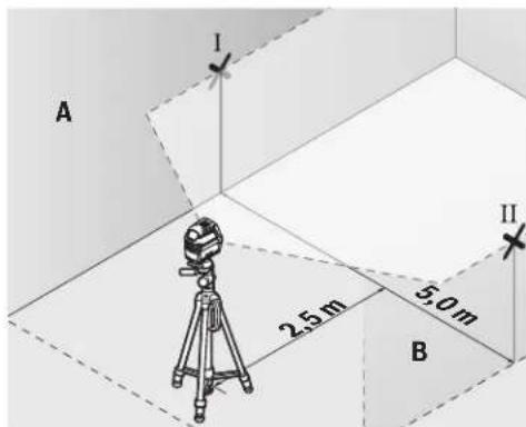
-Ha2,5m pactojaHne OJ MEPnOT ypeN,HaBata snaO3haeTe ja cpeHHata Ha nacepckata mHHja (Touka I Ha SIOT A N TOUKA II HA SIOT B).
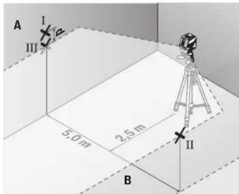
-Notabete ro MEPHnOtypei,cbpteh 3a 180°Ha5mpactojaHne nocabete ro da ce HNBennpa.
-Notabete ro mepnnot ypeid no BnCnHa (co nomou Ha CTaTHBOT HIN eBHTyAINHO CO nOtnorata), Taka wTO CpeHnHATA ha nacepcknte Hnnn ToHoo ke ja nOrO npTeXoHNO 03hauheHATA ToKa II Ha sIodT B.
Ha snoT A oBeneKeTe ja cpeHnHa Ta Ha nacepckata nnHja kako toka III (BeptnKaHHO Hnn noi tokataI).
- Pa3nKkata d Ha nBete O3HaueHn TouKn I n III Ha sNDOT A ro daBa oakTHKoTO OTCTanyBaHe Ha MepHNOTypeOxD xOpN30HTanata.
HaMepHaIHHJaOg2x5m=10m ro DaBa MaKcHMaHOTo 03BOnHeO OToTanyBaHe:
10m×0,3mm/m=±3mm.Pa3nKata dmery tockte I Icme da n3ncyba Hajmhory 3 mm.
PpOBepKa Ha ToUHOCTa HA HHBENHPaBeto Ha BepTtKJIHATAIHHJa
3a KOHTpOJa Notpe6eBn e O TBOp OD BpAtata, KaIe (Ha QBpCTa NoDnora) Ha Cekoja cTpaHa oD BpAtata MmA MeCTO oHajMaNKy 2,5 m.
-Noctabete ro mepnnot ypeHa 2,5 m pactojanhe od OTBOPOT Ha BpataHa uBpCTa, paMHa noDnora (He Ha cTaNb). IV36peTe ro BEPTKANHOT NHHNCKPekHM CO
aBtOMaTHKaTa 3a HnBEnIpaHbe.HacOyete ja nacepckata JINHJa HA OTBOPOT OJ BpATA N OCTABete rO MEPHnotype da HnBEnIpa.

-O3haueje ja cpeHHaHa BeptnKaHata nacepcka IHHja Ha NODOT OD OTBOPOT Ha Bpata (Touka I), Ha 5 m pactoJahne Ondpyrata CTpaHa Ha OTBOPOT OD Bpata (Touka II), KAKO HA TropHnOt paHa BpataOd OTBOPOT (Touka III).
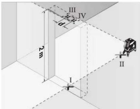
-CBpTeTo MepHnOype3a180NocTaBeTo Ha Dpyrata CtpaHa HAOTBOPoT HbPaTAtuNPeKTHO 3aI TOkATA II.OCTaBeTo MepHnOypeD aCe HNBEnPnHa HacOHte Ja BepTKaHHTa NacePcKa NHHJa Taka ITO HeJ3HNATA CpeHnA Ke NOMHyBa ToHQ H3 ToKITe I HII.
-ObenekeTe ja cpeHnHa Ta Ha nacepckata HnHjA Ha roHHOT paH hO TBOPoH h BpaTa KaKo ToKa IV.
PaNkata dHa DBeTe O3HaeHn Tockn IIN IV ro daBa KaTHKOTO OTCaYBaBe Ha MEPHHOTypeoD BePTHKaHHTe HHH.
-Imepete ja BcHnHaTa Ha OTBOPoT ObPata.
MaKCHMANHOIO3BOHe OTOCTanyBaHe ro npecMeTyBaTe
Ha CNEHNOT HauHH:
IBOJHa BcHnHa Ha OTBOPoT Ha Bpata × 0,3mm / m PiHMeP: PnBcHnHa Ha OTBOPoT Ha BpataOd 2m
MaKCHMANHOTo OTCTanyBaHe cMee Da IaN3ecyBa 2× 2m× ± 0,3mm / m = ± 1,2mm .Tockte III IV Cmeat
daJeXaT HajMHOry 1,2 mm eoHa oDpyra.
IpoBepKa Ha ToUHocTa Ha NaacepCKnOT ChON
3a npoBepkata Notpe6ha Bn e cno6DHa MepHa nnHja Ha Upcta noIora co pactojahne od okony 5 m nomery noot H nnafohot.
-MoHTnpajTe ro MEPHnOT ypeHa potaHNOHnO TpJxau (13) nocTabeTe ro Ha noDTo. N3bepete ro TOUKeCTNoT peKIMn HocTabeTe ro MEPHnOT ypeDa ca HNBenpa.
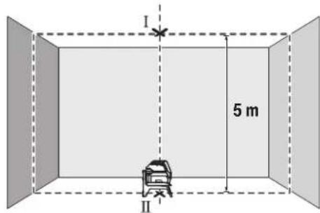
O3haeTe ja cpeHnHaTa Ha rohpTa Iacepcka Touka Ha nnafohoT (TOkaI).OCBeH ToA, obeJeKeTe ja cpeHnHaTa HA DOJIHATA Nacepcka TOKa Ha NooT (TOka II).

-Cbptete ro mepnot ype3a 180°.No3nnoHnpajte ro Ha Toj HauHH, ITO cpeHHata Ha DOnHATA nacepcka Tocka Ke Jekn Ha BeKe oBeJexKaHATA TOKA II. OctabeTe ro mePNOT ype da CE HBeInpa. OBeJexKete ja cpeHHata Ha rOpHata nacepcka Tocka (Tocka III).
Pa3nKaTa dHaDbete O3HaueHn ToKn I I IHa nnafoHOT roDaba 0aKTHUKOTo OTCTanyBaHe Ha MepHNOypeoI OBeTnKaHHTe HINHN.
MaKcImaHnHO ToO3B0neHo OTCTanyBaIbe ro npecmetyBaTe HA CNEHNOT HauHH:
ДбоJO pacoJOHHe Mery noOT nIpaHOHT xO,7 mm/m.
Ппмер: ПпрacoJOHHe Mery noOT nIpaHOHT od 5 m
MAKCMaHOT OTO CTAnyBaHe CmEe Da N3HecyBa
2x5m x ±0,7mm/m = ±7mm.ToUkTe I n III cMeat da
JIeKaT HajMHOry 7 mm edHa OD npyra.
Cobetn npa6oBeTeO
3a 06eKyBaBe KOpHcTeTe ja cekoraW cpeHnata Ha nacepckaTAt TOkA OHN. nacepckTa HnHna.
TolemHHata Ha Iacepckata ToKa OJH. WnPHata Ha Iacepckata HHHja ce MeHyBa cOrnaCHO pactoJAHHeTO.
194|MaKeDoHcKn
Pa6oTehe co cTaMb (onpeMa)
CtANBOT OBO3MOxByBa Cta6HnHa MepHa NODnora 1to MoKe da ce noDecyBa NO BHCnHa. NoCTabete ro MePHNOT ypeD co 1/4"-npnФaT0 HA CTAnBOT (9) Ha HABoJOT Ha CTAnBOT (22) nHbOuH e fTO cTAnHB. 3a npnBpCTyaBaHe Ha oBueh rpaedexe cTAnHB, KopHCTe 5/8"-npduat 3a cTAnHB (10). 3aBpCTe Ro MePHNOT ypeD co 3aBpTKa 3aФHKcPapBe Ha CTAnBOT.
Ipy6o ceHTpnpajTe ro ctaHBoT, nped da ro BknyuHte MEPHNOTypeD.
Pnucpctete co yHnBep3aneH dpXau (onpeMa) (BnH cnka G)
Co nOMOu Ha yHnBep3aHnHOT dpKau (18) MoKe da ro npuBpcTHTe MePHNOTypeHa np. Ha BepTNKaHn NOBpHHH Hm MarHeTHnPaHm MatepnJann. YHnBep3aHnHOT dpKau HnCTo Taka NoroDeH N Kako NoJeH CTaTMB H r OoneChyBa NoDecyBaBeTo No BnCnHa Ha MepHnOTypeD.
Ipy6o ceHTnpajTe ro yHnBep3aJIHHOT dpKaU (18), nped da ro BKNyUHTe MePHNOType.
Pabotebe co zenha Tabna 3a nacepot (Bnncn G)
Lcennata Ta6na 3a nacepot (19) ja noio6pyBa BnInBOCTa Ha nacepcknot 3paK npH HeNoBOnH yCNOBn I Roiemn pactoJAHJa.
PePnKtpaKaTnONOBHaHaeHtA TabHa HaNacepOT (19) jaNoOp6pyBa BnINbOcTa Ha Nacepckata HnHja, Hn3 TpaHcapapeHTHa NoOBHa Nacepckata HnHja e BnINbHa oD 3aHaTCTpaHa Ha eHtA TaBHa HaNacepOT.
Iacepckn 3aunTHn ouHa (onpeMa)
Iacepckte 3aHTTHO uHna ja HnntpHaat OKoHata CBETnHa. Ha Toj hauHH CBeTNO To HA nacepot Nsrrnep a nocBETNo 3a OKOTo.
He HN KOpHCTe NacepCKHTe 3aHTTHN OUYNA KaKo 3aHTTHN OUYNA. NacepCKHTe 3aHTTHN OUYNA cNYKaT 3a noD6po paCnO3HaBaHe Ha NacepCKNt 3paK; cenA, THe He WHTAT OD NacepCKTO 3paueBe.
He nKopnCTe Nacepcknte 3aunTHN Oounna KaO Oounna 3a coHne HnN NAK BO COoBpaKaJOT. Nacepcknte 3aunTHN Oounna He daBaat cenoCHA UV-3aunTnI a I Ho HaMaNyBaat npen03HabHeTo Ha 6On.
PpHmepn 3a pa6oTa (BnDn CnKn B2-F2,Gn H)
PpHmepn 3a MoKHOCTHe Ha pHmeha Ha MEPHHOTypeKe HajTe Ha rpaNcHTe CTpaHnC.
Mepnnot ypecltabje ro cekoraaw 6bncky do nobpwnhata nnpaobot, konsto tpe6a da ce npoBepat, nocTaBeTe ro da ce hHbEnHpnped noeTOKOT HA cekoe Mepehe.
CekoraMepete rnpactojaHjata MeFy nacepcknOT 3paK INOBpHHaTAtnnPaBtHaDBe mTO e MOXHO NooDnaJeEH TOCKN.
OdpKyBaBe H cepBnC
OdpKyBaBe nHcTeHe
NoctoJahO OndjKyaBajTe jaHcTotaHa MepeHnOtypeI.
He ro notonybajTe MepHnotypeB BO BODa Hn DpyrnteHuOCTN.
I36pnwete rH HeunctOHTnne co BnaXHa MeKa Kpna. He KopnCTe CpeCDtBA 3a YHe Tbe NnPacTBOpH.
PeNoBHO NCHTeTn NOBpHHNHTe OKNY H3Ne3HNO TOT BOP Ha nacepotn npToa BHnMaBaJte Ha BnakHeuTa.
CepBncha cny6a n COBET npKOpHCTeHe
CepBnchata cnyk6a Ke OndroBOpn Ha BaunTe npaaBa BO Bpcka co nonpaBkata H OndjxyBaBeTo Ha Baunot npon3BOD KAKo Hpe3epBNHTe DeIOBn. O3NaKu 3a ekcnloanja HnHΦopMaun 3a pe3epBNHTe DeIOBn HcTo Taka Ke HajTe Ha: www.bosch-pt.com
TMMOTa cOBeTyBaHe npn KOpHcTeHe Ha Bosch Ke BN NOMORHe DOKOLKy HMaTe PpaHaBa 3a HaaHTe PpOIN3BOOni ONpema.
3a cIte npaaHb HapaKHa Ha peepBn DeIOBn,Be MoIhme HabeTe ro 10-uzppeHnot 6poj od CneuФнkaunHATA nOuKa Ha npOn3BODoT.
MaKeDoHnJa
Д.Д.Енковский
CabaKobayek47b,6poj3
1000 Ckonje
E-nouta: dimce.dimcev@servis-bosch.mk
HHTepHET: www.servis-bosch.mk
Ten./φακc:02/2467610
Mo6:070595888
A.I.T.Y "POJKA"
JaHnykpOBckn 66;T.L ABTOKOMaHaJnokan 69
1000 Ckonje
E-nowta: servisrojka@yahoo.com
Ten: +38923174-303
Mo6: +389 70 388-520, -530
OctpaHyBaBe
MepHHe ypeHn, onpemata n ambaJanaKeTe tpe6a da ce OTCpaHaT ha ekolooKN pnpafNHB hauH.

He nФрпajte Мернite ypei n 6aTePnnte BO domaunHata KaHTa 3a OTnadoOn!
Cama 3a 3emjnte oEY:
CnopeE EBpOcKa TnpeKTHBa 2012/19/Eu MepHnTe ypeNTo Ce BOH yNoTpe6a NdepeKTHte HnN NckopHeHte BateHH CnopeDnpeKTHBaTa 2006/66/EC Mopa OdienHO da ce co6epa n da ce peuknpaat 3a NOBtphy yNoTpe6a.
Srpski
Tezina prema
EPTA-Procedure 01:2014
Dimenzije (duljina × sirina × visina)
- bez okretnog drzača 112 × 55 × 106 mm 112 × 55 × 106 mm
-sokretnim drzaem 132× 81× 163mm132× 81× 163mm
Vrsta zašite IP 54 (zašićeno od
0,49kg0,49kg
IP 54 (zašićeno od
prasine i prskanja vode)
prasei prskanja vode)
Darbs ar stativu (papildiederums)
Stativs ir ieriece ar reguljema augstumu, kas paredzeta merinstrumenta stabilai nostiprinaanai. Izmantojot merinstrumenta 1/4" vitni (9) nostipriniet to uz stativa (22)
vitnes vai ari uz parastafotostativa, ko var iegadaties tirdzniecibas vietas. Lai merinstrumentu nostiprinatu uz tirdzniecibas vietas pieejama celtniecibas stativa, izmantojiet 5 / 8" stiprino so vitni (10). Stingri pieskrveijet merinstrumentu ar stativa stiprinajuma skruvi. Pirms merinstrumenta ieslegsanas aptuveni izlidziniet stativu.
Nostiprinasana ar universalā turetaja palidzibu (papildiederums) (attels G)
Ar universala turetaja (18) palidzibu merinstrumentu var
nostiprinat, piemar, uz stateniskam virsmam, caurlem
vai magnetiskiem materieliem. Universalais turetajs ir
izmantojams ari ka uz zemes novietojams stativs, atvieglojot
merinstrumenta nostipinasa naru velamaja augstuma.
Pirms merinstrumenta ieslegsanas aptuveni izlidziniet
universalo turetaju (18).
Darbs ar lazera merkplaksni (attels G)
Lazera merkplaksne (19) lauj uzlabot Lazera staru redzambu nelabveligos darba apstaklos un liela attaluma.
Lazera skatbrilles (papildiederums)
Lazera skatbrillem piem itipasiba aizturetpakartejo gaismu, tapec Lazera stars acim liekas spilgtsaks.
Nelietojiet lazera skatbrilles ka aizsargbrilles. La zera skatbrilles ir paredzetas lazera stara redzamibas uzlabosanai, tacu tas nespj pasargat acis no lazera starojuma.
Nelietojet lazera skatbrilles ka saules brilles vai ka aizsargbrilles, vadot satiksmes lidzekli. Lazer skatbrilles nenodrosina pilnvertigua aizsardzibu no ultravioleta starojuma un paslktina krasu izskiranas spju.
Darba operaciju piemeri (atteli B2-F2, G un H)
首詠公司的前用到前用(8)“On"(自通雷则昌能明山)无在“On"(自动雷贝则昌有),将之即日者。
ReiJtJIiIiIiIiIiIiIiIiIiIiIiIiIiIiIiIiIiIiIiIiIiIiIiIiIiIiIiIiIiIiIiIiIiIiIiIiIiIiIiIiIiIiIiIiIiIiIiIiIiIiIi
栽藻藻皂藻藻皂藻藻藻藻藻藻藻藻藻藻藻藻藻藻藻藻藻藻藻藻藻藻藻藻藻藻藻藻藻藻藻藻藻藻藻藻藻藻藻藻藻藻藻藻藻藻藻藻藻藻藻藻藻藻藻藻藻藻
| 製作사선서 涑명선형모 | USB USB USB USB USB USB USB USB USB USB USB USB USB USB USB USB USB USB USB USB USB USB USB USB USB USB USB USB USB USB USB USB USB USB USB USB USB USB USB USB USB USB USB USB USB USB USB USB USB USB USB | USB USB USB USB USB USB USB USB USB USB USB USB USB USB USB USB USB USB USB USB USB USB USB USB USB USB USB USB USB USB USB USB USB USB USB USB USB USB USB USB USB USB USB USB USB USB USB USB USB usb usb usb usb usb usb usb usb usb usb usb usb usb usb usb usb usb usb usb usb usb usb usb usb usb usb usb usb usb usb usb usb usb usb usb usb usb usb usb usb usb usb usb usb usb usb usb usb usb usb USB USB USB USB USB USB USB USB USB USB USB USB USB USB USB USB USB USB USB USB USB USB USB USB USB USB USB USB USB USB USB USB USB USB USB USB USB USB USB USB USB USB USB USB USB USB USB USB USB usb |
“自通R洛贝L能M社人歌”MoD上者T是R
- 青龍宮公寺,藏在西藏自治区西藏自治区,藏在西藏自治区西藏自治区西藏自治区西藏自治区西藏自治区西藏自治区西藏自治区西藏自治区西藏自治区西藏自治区西藏自治区西藏自治区西藏自治区西藏自治区西藏自治区西藏自治区西藏自治区西藏自治区西藏自治区西藏自治区西藏自治区西藏自治区西藏自治区西藏自治区西藏自治区西藏自治区西藏自治区西藏自治区西藏自治区西藏自治区西藏自治区西藏自治区西藏自治区西藏自治区西藏自治区西藏自治区西藏自治区西藏自治区西藏自治区西藏自治区西藏自治区西藏自治区西藏自治区西藏自治区西藏自治区西藏自治区西藏自治区西藏自治区西藏自治区西藏自治区西藏
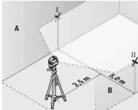
- 皂藥兵贼藻士青峰詠贈公莊羅末托2.5m毫早藏子起利里贝士拉在的中位将五山(贼A)扎员[且兵B]志
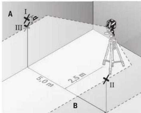
IeTeStre to haeRanBakd and 10000000000000000000000000000000000000000000000000000000000
- 青豐公国,到中(13)用,,
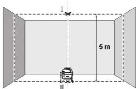
- 朝登用伏秋莱贝子托印在的,即士如().
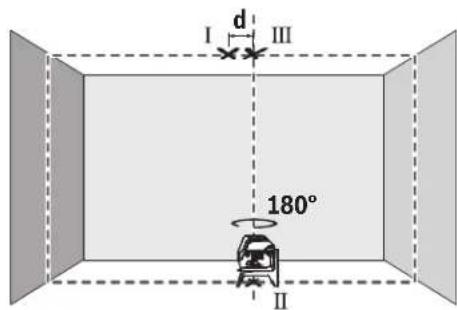
DnAnanAnAnAnAnAnAnAnAnAnAnAnAnAnAnAnAnAnAnAnAnAnAnAnAnAnAnAnAnAnAnAnAnAnAnAnAnAnAnAnAnAnAnAnAnAnAnAnAnAnAnAnAnAnAnAnAnAnAnAnAn
wn "On" (nwnnnnunwauuunnnnnnnnnnnnnnnnnnnnnnnnnnnnnnnnnnnnnnnnnnnnnnnnnnnnnnnnnnnnnnnnnnnnnnnnnnnnnnnnnnnnnnnnnnnnnnnnnnnnnnnnnnnnnnnnnnnnnnnnnnnnnnnnnnnnnnnnnnnnnnnnnnnnnnnnnnnnnnnnnn nn nannn nn nannn nn nannn nn nannn nn nannn nn nannn nn nannn nn nannn nn nannn nn nannn nn nannn nn nannn nn nannn nn nannn nn nannn nn nannn nn nannn nn nannn nn nannn nn nannn nn nannn nn nannn nn nannn nn nannn nn nannn nn nennn nn nannn nn nannn nn nannn nn nannn nn nannn nn nannn nn nannn nn nannn nn nannn nn nannn nn nannn nn nannn nn nannn nn nannn nn nannn nn nannn nn nannn nn nannn nn nannn nn nannn nn nannn nn nannn nn nannn nn nannn nn n ann
aannnnnnae annnnnne aannnnnne
iOnnnnnaaonnnnnae nnneaaanennnnae-08)
aannnnnnae aen nnnnne eae
nnaaannnnnnnnnnnnnnnnnnnnnnnnnnnnnnnnnnnnnnnnnnnnnnnnnnnnnnnnnnnnnnnnnnnnnnnnnnnnnnnnnnnnnnnnnnnnnnnnnnnnnnnnnnnnnnnnnnnnnnnnnnnnnnnnnnnnnnnnnn
T
mnnnnaannnnaaennnnnnnnnnnnnnnnnnnnnnnnnnnnnnnnnnnnnnnnnnnnnnnnnnnnnnnnnnnnnnnnnnnnnnnnnnnnnnnnnnnnnnnnnnnnnnnnnnnnnnnnnnnnnnnnnnnnnnnnnnnnnnnnnn
nannnnnnaaennnnnne nnnnnnnnnnnnnnnnnnnnnnnnnnnnnnnnnnnnnnnnnnnnnnnnnnnnnnnnnnnnnnnnnnnnnnnnnnnnnnnnnnnnnnnnnnnnnnnnnnnnnnnnnnnnnnnnnnnnnnnnnnnnnnnnnn nn
nannnnnnnnnnnnnnnnnnnn
nannnnnnnnnnnnnnnnnnnnnnnnnnnnnnnnnnnnnnnnnnnnnnnnnnnnnnnnnnnnnnnnnnnnnnnnnnnnnnnnnnnnnnnnnnnnnnnnnnnnnnnnnnnnnnnnnnnnnnnnnnnnnnnnnnnnnnnnnnnnnnnnnnnnnnnnnnnn
mnnnnaaannnnn 45oC aiananrnnn
nannnnnnnnnnnnnnnnnnnnnnnnnnnnnnnnnnnnnnnnnnnnnnnnnnnnnnnnnnnnnnnnnnnnnnnnnnnnnnnnnnnnnnnnnnnnnnnn
yuguaunun
一nnnnnnnnnnnnnnaa:nuu: nnnnnnnnnnnnnnnnnnnnnnnnnnnnnnnnnnnnnnnnnnnnnnnnnnnnnnnnnnnnnnnnnnnnnnnnnnnnnnnnnnnnnnnnnnnnnnnnnnnnnnnnnnnnnnnnnnnnnnnnnnnnnnnnnn nnannn
- 1777777777777777777777777777777777
-777777777777777777777777777777777777777777777777 13333333333333333333333333333333333
一nannnnnnae:
nannnnnnnnnnnnnnnnnnnnnnnnnnnnnnnnnnnnnnnnnnnnnnnnnnnnnnnnnnnnnnnnnnnnnnnnnnnnnnnnnnnnnnnnnnnnnnnnnnnnnnnnnnnnnnnnnnnnnnnnnnnn
m|273
nannnnnnnnnnnnnnnnnnnnnnnnnnnnnnnnnnnnnnnnnnnnnnnnnnnnnnnnnnnnnnnnnnnnnnnnnnnnnnnnnnnnnnnnnnnnnn
| ### | ### | ### | ### | ### | ### |
| (3) | |||||
| ### | (8) | "On" | ●●●B1 | □ | |
| ### | □ | ||||
| + | n1 0 ### | ●-●C1 | □ | ||
| n2 0 ### | -●●D1 | □ | |||
| n3 0 ### | -●●E1 | □ | |||
| n4 0 ### | ●●●B1 | □ | |||
| n5 0 ### | -●●E1 | □ | |||
| n6 0 ### | ●●●B1 | □ | |||
| n7 0 ### | -●●E1 | □ | |||
| n8 0 ### | ●●●B1 | □ | |||
| n9 0 ### | -●●E1 | □ | |||
| n10 0 ### | ●●●B1 | □ |
nnuuuluidnnnnaeun
luu"nnnuuulnueuuuunnnnnaeauu" uuuuuuuuuuuuuuuuuuuuuuuuuuuuuuuuuuuuuuuuuuuuuuuuuuuuuuuuuuuuuuuuuuuuuuuuuuuuuuuuuuuuuuuuuuuuuuuuuuuuuuuuuuuuuuuuuuuuuuuuuuuuuuuuuuuuuuuuuuuuuuuuuuuuuuuuuuuuuuuuuuuuuuuuuuuuuuuuuuuuuuuuuuuuuuu
nTnTnTnTuTnTu
nannnnnnnnnnnnnnnnnnnnnnnnnnnnnnnnnnnnnnnnnnnnnnnnnnnnnnnnnnnnnnnnnnnnnnnnnnnnnnnnnnnnnnnnnnnnnnnnnnnnnnnnnnnnnnnnnnnnnnnnnnnnnnnnnnnnnnnnnnnnnnnnnnnnnn
777777777777777777777777777777777777777777777
180° 1uuiuuaaunauan uan A uanuee nnnaaannnnn an nnnn an annn an an an an an an an an an an an an an an an an an an an an an an an an an an an an an an an an an an an an an an an an an an an anan a (aa)
一nna d 2x5u.10u.n
Palma Tower 10th Floor
Jalan RA Kartini II-S Kaveling 6
Pondok Pinang, Kebayoran Lama
Don nguyen 8BC, GT Tower, Tang 08,
Durog 169, Tiep Khac Blvd, Sangkat Veal Vong,
Khan 7 Makara, Phnom Penh
VAT TIN: 100 169 511
Tel.: +855 23 900 685
Tel.: +855 23 900 660
www.bosch.com.kh
Su'thai bo
Dung cu do, phu kien va bao bi phai duoc phan loai de tai che theo huong than thien voi mi truong.

Khong vut dung cu do va pin cung trong rac thai cua gia dinh!
UJJjU UbgbsuJU Jcoglc.2
wull osc u wu wu 5 gJgJgJgJgJ 10
cJ 15.53 aclw 10 saoj oJgJyogll
gjolg jjuIbgb aogj, uJbll a
logg|aLjU
Lc paiol.ogll maoj g Uy IuIbU US
.0jdlg gill jai no 1uulp
pse wjll oo Uyulg jil
1suiSsuUull.ajjIgssi
aIgblqjaiuLjilqiuw j
.
jbl) RM1 jlgdl Jolal Jdawly Jdll
(A3-A1gJgJl
0sc 1(13)1gUU UoUU
aJydoJeabooJgda360agj(uall
aJy jU bgs buu JSo uug. lois ajo
.(w)
(7)JUJI JJOLIJAOWUJUAIJI 8scuS
JgJlJolal (14) Jll Jll Jc
LiaaiJ Lc sggal wllg 1g (13)
.
gJgJlJolJnJwJll6c JsI,
.
297
Jagj,asuoggI gai jai aai gai J 2o45 Juswll oji a jcb13:abaloo .aiai aai gai jnsay
Jusill Egi b
Jgag Jgag Jgag Jgag Jgag Jgag Jgag Jgag Jgag Jgag Jgag Jgag Jgag Jgag Jgag Jgag Jgag Jgag Jgag Jgag Jgag Jgag Jgag Jgag Jgag Jgag Jgag Jgag Jgag Jgag Jgag Jgag Jgag Jgag J
UulgJglpaLw2L
Jg J11 1
Jolai Jalb1/ Juswul alao 8
Joui aui lae Siie.Offg U (8)laby
jdi 5dag
aJgJusuill s
LglsswI dy wll oocabg p 1
jUe uunnuiu uauu!
0jra ddu jgl aic lalbplu
Lgagaaulll50paaoaagp
Sue yu wll wll ooc gmoi jlll jlll
. Siie glawo 1 nKg uill
aai aii
120JUWUULOscab
. 1
/JeuIeIeIeIeIeIeIeIeIeIeIeIeIeIeIeIeIeIeIeIeIe I
. (5) jJIJIbIaJIJIJIJIJIJIJIJIJIJIJIJIJIJIJIJIJIJIJIJIJIJIJIJIJIJIJIJIJIJIJIJIJIJIJIJIJIJIJIJIJIJIJIJIJIJIJIJIJIJIJIJIJIJIJIJIJIJIJIJIJIJIJIJIJIJIJIJIJIJIJIJIJIJIJIJIJIJIJIJIJIJIJIJIJIJIJIJIJIJIJIJIJIJIJIJIJIJIJIJIJ
JUeUeUeUeUeUeUeUeUeUeUeUeUeUeUeUeUeUeUeUeUeUeUeUeUeUeUeUeUeUeUeUeUeUeUeUeUeUeUeUeUeUeUeUeUeUeUeUeUeUeUc
JiJiJiJiJiJiJiJiJiJiJiJiJiJiJiJiJiJiJiJiJiJiJiJiJiJiJiJiJiJiJiJiJiJiJiJiJiJiJiJiJiJiJiJiJiJiJiJiJiJiJ i
a g u w u a j go JuaW
| öjgäll | öjgäll öjgäll öjgäll öjgäll öjgäll öjgäll öjgäll öjgäll öjgäll öjgäll öjgäll öjgäll öjgäll öjgäll öjgäll öjgäll öjgäll öjgäll öjgäll öjgäll öjgäll | öjgäll öjgäll öjgäll öjgäll öjgäll öjgäll öjgäll öjgäll öjgäll öjgäll öjgäll öjgäll öjgäll öjgäll öjgäll öjgäll öjgäll öjgäll öjgäll | öjgäll | öjgäll | öjgäll | öjgäll | öjgäll | öjgäll |
| B1 | 6 | ● | ● | ● | ● | ● | ● | ● |
| C1 | 6 | ● | - | ● | ● | ● | ● | ● |
| D1 | 6 | ● | ● | - | ● | ● | ● | ● |
| E1 | 6 | ● | - | - | ● | ● | ● | ● |
| B1 | 6 | ● | ● | ● | ● | ● | ● | ● |
| 6 | ● | logbpgall logbpgall logbpgall logbpgall logbpgall logbpgall logbpgall logbpgall logbpgall logbpgall logbpgall logbpgall logbpgall logbpgall logbpgall logbpgall logbpgall logbpgall logbpgall logbpgall logbpgall | logbpgall logbpgall logbpgall logbpgall logbpgall logbpgall logbpgall logbpgall logbpgall logbpgall logbpgall logbpgall logbpgall logbpgall logbpgall logbpgall logbpgall logbpgall logbpgall logbpgull logbpgull logbpgull logbpgull logbpgull logbpgull logbpgull logbpgull logbpgull logbpgull logbpgull logbpgull logbpgull logbpgull logbpgull logbpgull logbpgull logbpgull logbpgull logbpgull logbpgoll logbpgoll logbpgoll logbpgoll logbpgoll logbpgoll logbpgoll logbpgoll logbpgoll logbpgoll logbpgoll logbpgoll logbpgoll logbpgoll logbpgoll logbpgoll logbpgoll logbpgoll logbpgoll logbpgoll logbpgull logbpgull logbpgull logbpgull logbpgull logbpgull logbpgull logbpgull logbpgull logbpgull logbpgull logbpgull logbpgull logbpgull logbpgull logbpgull logbpgull logbpgull logbpgull logbpgell logbpgell logbpgell logbpgell logbpgell logbpgell logbpgell logbpgell logbpgell logbpgell logbpgell logbpgell logbpgell logbpgell logbpgell logbpgell logbpgell logbpgell logbpgell logbpgell logbpgill logbpgill logbpgill logbpgill logbpgill logbpgill logbpgill logbpgill logbpgill logbpgill logbpgill logbpgill logbpgill logbpgill logbpgill logbpgill logbpgill logbpgill logbpgill logbpgill logbpgell logbpgill logbpgill logbpgill logbpgill logbpgill logbpgill logbpgill logbpgill logbpgill logbpgill logbpgill logbpgill logbpgill logbpgill logbpgill logbpgill logbpgill logbpgill logbpgell logbpgell logbpgill logbpgill logbpgill logbpgill logbpgill logbpgill logbpgill logbpgill logbpgill logbpgill logbpgill logbpgill logbpgill logbpgill logbpgill logbpgill logbpgill logbpgell logbpgill logbpgell logbpgill logbpgill logbpgill logbpgill logbpgill logbpgill logbpgill logbpgill logbpgill logbpgill logbpgill logbpgill logbpgill logbpgill logbpgill logbpgill logbpgill logbpgell logbpgell logbpgell logbpgill logbpgill logbpgill logbpgill logbpgill logbpgill logbpgill logbpgill logbpgill logbpgill logbpgill logbpgill logbpgill logbpgill logbpgill logbpgill logbpgell logbpgill logbpgill logbpgell logbpgill logbpgill logbpgill logbpgill logbpgill logbpgill logbpgill logbpgill logbpgill logbpgill logbpgill logbpgill logbpgill logbpgill logbpgill logbpgill logbpgell logbpgill logbpgell logbpgell logbpgill logbpgill logbpgill logbpgill logbpgill logbpgill logbpgill logbpgill logbpgill logbpgill logbpgill logbpgill logbpgill logbpgill logbpgill logbpgill logbpgell logbpgell logbpgill logbpgell logbpgill logbpgill logbpgill logbpgill logbpgill logbpgill logbpgill logbpgill logbpgill logbpgill logbpgill logbpgill logbpgill logbpgill logbpgill logbpgill logbpgell logbpgell logbpgell logbpgell logbpgill logbpgill logbpgill logbpgill logbpgill logbpgill logbpgill logbpgill logbpgill logbpgill logbpgill logbpgill logbpgill logbpgill logbpgill logbpgell logbpgill logbpgill logbpgill logbpgell logbpgill logbpgill logbpgill logbpgill logbpgill logbpgill logbpgill logbpgill logbpgill logbpgill logbpgill logbpgill logbpgill logbpgill logbpgill logbpgell logbpgill logbpgill logbpgell logbpgell logbpgill logbpgill logbpgill logbpgill logbpgill logbpgill logbpgill logbpgill logbpgill logbpgill logbpgill logbpgill logbpgill logbpgill logbpgill logbpgell logbpgill logbpgell logbpgill logbpgell logbpgill logbpgill logbpgill logbpgill logbpgill logbpgill logbpgill logbpgill logbpgill logbpgill logbpgill logbpgill logbpgill logbpgill logbpgill logbpgell logbpgill logbpgell logbpgell logbpgell logbpgill logbpgill logbpgill logbpgill logbpgill logbpgill logbpgill logbpgill logbpgill logbpgill logbpgill logbpgill logbpgill logbpgill logbpgill logbpgell logbpgell logbpgill logbpgill logbpgell logbpgill logbpgill logbpgill logbpgill logbpgill logbpgill logbpgill logbpgill logbpgill logbpgill logbpgill logbpgill logbpgill logbpgill logbpgill logbpgell logbpgell logbpgill logbpgell logbpgell logbpgill logbpgill logbpgill logbpgill logbpgill logbpgill logbpgill logbpgill logbpgill logbpgill logbpgill logbpgill logbpgill logbpgill logbpgill logbpgell logbpgell logbpgell logbpgill logbpgell logbpgill logbpgill logbpgill logbpgill logbpgill logbpgill logbpgill logbpgill logbpgill logbpgill logbpgill logbpgill logbpgill logbpgill logbpgill logbpgell logbpgell logbpgell logbpgell logbpgell logbpgill logbpgill logbpgill logbpgill logbpgill logbpgill logbpgill logbpgill logbpgill logbpgill logbpgill logbpgill logbpgill logbpgill logbpgell logbpgill logbpgill logbpgill logbpgill logbpgell logbpgill logbpgill logbpgill logbpgill logbpgill logbpgill logbpgill logbpgill logbpgill logbpgill logbpgill logbpgill logbpgill logbpgill logbpgell logbpgill logbpgill logbpgill logbpgell logbpgell logbpgill logbpgill logbpgill logbpgill logbpgill logbpgill logbpgill logbpgill logbpgill logbpgill logbpgill logbpgill logbpgill logbpgill logbpgell logbpgill logbpgill logbpgell logbpgill logbpgell logbpgill logbpgill logbpgill logbpgill logbpgill logbpgill logbpgill logbpgill logbpgill logbpgill logbpgill logbpgill logbpgill logbpgill logbpgell logbpgill logbpgill logbpgell logbpgell logbpgell logbpgill logbpgill logbpgill logbpgill logbpgill logbpgill logbpgill logbpgill logbpgill logbpgill logbpgill logbpgill logbpgill logbpgill logbpgell logbpgill logbpgell logbpgill logbpgill logbpgell logbpgill logbpgill logbpgill logbpgill logbpgill logbpgill logbpgill logbpgill logbpgill logbpgill logbpgill logbpgill logbpgill logbpgill logbpgell logbpgill logbpgell logbpgill logbpgell logbpgell logbpgill logbpgill logbpgill logbpgill logbpgill logbpgill logbpgill logbpgill logbpgill logbpgill logbpgill logbpgill logbpgill logbpgill logbpgell logbpgill logbpgell logbpgell logbpgill logbpgell logbpgill logbpgill logbpgill logbpgill logbpgill logbpgill logbpgill logbpgill logbpgill logbpgill logbpgill logbpgill logbpgill logbpgill logbpgell logbpgill logbpgell logbpgell logbpgell logbpgell logbpgill logbpgill logbpgill logbpgill logbpgill logbpgill logbpgill logbpgill logbpgill logbpgill logbpgill logbpgill logbpgill logbpgill logbpgell logbpgell logbpgill logbpgill logbpgill logbpgell logbpgill logbpgill logbpgill logbpgill logbpgill logbpgill logbpgill logbpgill logbpgill logbpgill logbpgill logbpgill logbpgill logbpgill logbpgell logbpgell logbpgill logbpgill logbpgell logbpgell logbpgill logbpgill logbpgill logbpgill logbpgill logbpgill logbpgill logbpgill logbpgill logbpgill logbpgill logbpgill logbpgill logbpgill logbpgell logbpgell logbpgill logbpgell logbpgill logbpgell logbpgill logbpgill logbpgill logbpgill logbpgill logbpgill logbpgill logbpgill logbpgill logbpgill logbpgill logbpgill logbpgill logbpgill logbpgell logbpgell logbpgill logbpgell logbpgell logbpgell logbpgill logbpgill logbpgill logbpgill logbpgill logbpgill logbpgill logbpgill logbpgill logbpgill logbpgill logbpgill logbpgill logbpgill logbpgell logbpgell logbpgell logbpgill logbpgill logbpgell logbpgill logbpgill logbpgill logbpgill logbpgill logbpgill logbpgill logbpgill logbpgill logbpgill logbpgill logbpgill logbpgill logbpgill logbpgell logbpgell logbpgell logbpgill logbpgell logbpgell logbpgill logbpgill logbpgill logbpgill logbpgill logbpgill logbpgill logbpgill logbpgill logbpgill logbpgill logbpgill logbpgill logbpgill logbpgell logbpgell logbpgell logbpgell logbpgill logbpgell logbpgill logbpgill logbpgill logbpgill logbpgill logbpgill logbpgill logbpgill logbpgill logbpgill logbpgill logbpgill logbpgill logbpgill logbpgell logbpgell logbpgell logbpgell logbpgell logbpgell logbpgell logbpgell logbpgell logbpgell logbpgell logbpgell logbpgell logbpgell logbpgell logbpgell logbpgell logbpgell logbpgell logbpgll logbpgll logbpgll logbpgll logbpgll logbpgll logbpgll logbpgll logbpgll logbpgll logbpgll logbpgll logbpgll logbpgll logbpgll logbpgll logbpgll logbpgll logbpgll logbpgll logbpgell logbpgell logbpgell logbpgell logbpgell logbpgell logbpgell logbpgell logbpgell logbpgell logbpgell logbpgell logbpgell logbpgell logbpgell logbpgell logbpgell logbpgell logbpgell logbpgellas logbpgellas logbpgellas logbpgellas logbpgellas logbpgellas logbpgellas logbpgellas logbpgellas logbpgellas logbpgellas logbpgellas logbpgellas logbpgellas logbpgellas logbpgellas logbpgellas logbpgellas logbpgellas logbpgellas logbpgella logbpgellas logbpgellas logbpgellas logbpgellas logbpgellas logbpgellas logbpgellas logbpgellas logbpgellas logbpgellas logbpgellas logbpgellas logbpgellas logbpgellas logbpgellas logbpgellas logbpgellas logbpgellas logbpgellas logbpgell logbpgellas logbpgellas logbpgellas logbpgellas logbpgellas logbpgellas logbpgellas logbpgellas logbpgellas logbpgellas logbpgellas logbpgellas logbpgellas logbpgellas logbpgellas logbpgellas logbpgellas logbpgellas logbpgell logbpgell logbpgellas logbpgellas logbpgellas logbpgellas logbpgellas logbpgellas logbpgellas logbpgellas logbpgellas logbpgellas logbpgellas logbpgellas logbpgellas logbpgellas logbpgellas logbpgellas logbpgellas logbpgell logbpgellas logbpgell logbpgellas logbpgellas logbpgellas logbpgellas logbpgellas logbpgellas logbpgellas logbpgellas logbpgellas logbpgellas logbpgellas logbpgellas logbpgellas logbpgellas logbpgellas logbpgellas logbpgellas logbpgell logbpgell logbpgell logbpgellas logbpgellas logbpgellas logbpgellas logbpgellas logbpgellas logbpgellas logbpgellas logbpgellas logbpgellas logbpgellas logbpgellas logbpgellas logbpgellas logbpgellas logbpgellas logbpgell logbpgellas logbpgellas logbpgell logbpgellas logbpgellas logbpgellas logbpgellas logbpgellas logbpgellas logbpgellas logbpgellas logbpgellas logbpgellas logbpgellas logbpgellas logbpgellas logbpgellas logbpgellas logbpgellas logbpgell logbpgellas logbpgell logbpgell logbpgellas logbpgellas logbpgellas logbpgellas logbpgellas logbpgellas logbpgellas logbpgellas logbpgellas logbpgellas logbpgellas logbpgellas logbpgellas logbpgellas logbpgellas logbpgellas logbpgell logbpgell logbpgellas logbpgell logbpgellas logbpgellas logbpgellas logbpgellas logbpgellas logbpgellas logbpgellas logbpgellas logbpgellas logbpgellas logbpgellas logbpgellas logbpgellas logbpgellas logbpgellas logbpgellas logbpgell logbpgell logbpgell logbpgell logbpgellas logbpgellas logbpgellas logbpgellas logbpgellas logbpgellas logbpgellas logbpgellas logbpgellas logbpgellas logbpgellas logbpgellas logbpgellas logbpgellas logbpgellas logbpgell logbpgellas logbpgellas logbpgellas logbpgell logbpgellas logbpgellas logbpgellas logbpgellas logbpgellas logbpgellas logbpgellas logbpgellas logbpgellas logbpgellas logbpgellas logbpgellas logbpgellas logbpgellas logbpgellas logbpgell logbpgellas logbpgellas logbpgell logbpgell logbpgellas logbpgellas logbpgellas logbpgellas logbpgellas logbpgellas logbpgellas logbpgellas logbpgellas logbpgellas logbpgellas logbpgellas logbpgellas logbpgellas logbpgellas logbpgell logbpgellas logbpgell logbpgellas logbpgell logbpgellas logbpgellas logbpgellas logbpgellas logbpgellas logbpgellas logbpgellas logbpgellas logbpgellas logbpgellas logbpgellas logbpgellas logbpgellas logbpgellas logbpgellas logbpgell logbpgellas logbpgell logbpgell logbpgell logbpgellas logbpgellas logbpgellas logbpgellas logbpgellas logbpgellas logbpgellas logbpgellas logbpgellas logbpgellas logbpgellas logbpgellas logbpgellas logbpgellas logbpgellas logbpgell logbpgell logbpgellas logbpgellas logbpgell logbpgellas logbpgellas logbpgellas logbpgellas logbpgellas logbpgellas logbpgellas logbpgellas logbpgellas logbpgellas logbpgellas logbpgellas logbpgellas logbpgellas logbpgellas logbpgell logbpgell logbpgellas logbpgell logbpgell logbpgellas logbpgellas logbpgellas logbpgellas logbpgellas logbpgellas logbpgellas logbpgellas logbpgellas logbpgellas logbpgellas logbpgellas logbpgellas logbpgellas logbpgellas logbpgell logbpgell logbpgell logbpgellas logbpgell logbpgellas logbpgellas logbpgellas logbpgellas logbpgellas logbpgellas logbpgellas logbpgellas logbpgellas logbpgellas logbpgellas logbpgellas logbpgellas logbpgellas logbpgellas logbpgell logbpgell logbpgell logbpgell logbpgell logbpgellas logbpgellas logbpgellas logbpgellas logbpgellas logbpgellas logbpgellas logbpgellas logbpgellas logbpgellas logbpgellas logbpgellas logbpgellas logbpgellas logbpgell logbpgellas logbpgellas logbpgellas logbpgellas logbpgell logbpgellas logbpgellas logbpgellas logbpgellas logbpgellas logbpgellas logbpgellas logbpgellas logbpgellas logbpgellas logbpgellas logbpgellas logbpgellas logbpgellas logbpgell logbpgellas logbpgellas logbpgellas logbpgell logbpgell logbpgellas logbpgellas logbpgellas logbpgellas logbpgellas logbpgellas logbpgellas logbpgellas logbpgellas logbpgellas logbpgellas logbpgellas logbpgellas logbpgellas logbpgell logbpgellas logbpgellas logbpgell logbpgellas logbpgell logbpgellas logbpgellas logbpgellas logbpgellas logbpgellas logbpgellas logbpgellas logbpgellas logbpgellas logbpgellas logbpgellas logbpgellas logbpgellas logbpgellas logbpgell logbpgellas logbpgellas logbpgell logbpgell logbpgell logbpgellas logbpgellas logbpgellas logbpgellas logbpgellas logbpgellas logbpgellas logbpgellas logbpgellas logbpgellas logbpgellas logbpgellas logbpgellas logbpgellas logbpgell logbpgellas logbpgell logbpgellas logbpgellas logbpgell logbpgellas logbpgellas logbpgellas logbpgellas logbpgellas logbpgellas logbpgellas logbpgellas logbpgellas logbpgellas logbpgellas logbpgellas logbpgellas logbpgellas logbpgell logbpgellas logbpgell logbpgellas logbpgell logbpgell logbpgellas logbpgellas logbpgellas logbpgellas logbpgellas logbpgellas logbpgellas logbpgellas logbpgellas logbpgellas logbpgellas logbpgellas logbpgellas logbpgellas logbpgell logbpgellas logbpgell logbpgell logbpgellas logbpgell logbpgellas logbpgellas logbpgellas logbpgellas logbpgellas logbpgellas logbpgellas logbpgellas logbpgellas logbpgellas logbpgellas |
298|
aJSo! 1gI Jaaai lai pii "On gaggl (8) aJauu o uu uuuu
a gill a jg.5
Jai IqI loS, aauuui I gaoa 1 o ao
1gJJI JooJJ
(HgG,F2-B2 jgJl jil) JooJdio
yulal oocolaiawaiol
aababulgwwul
gI abuI joo uao (le lai (wauo ooc
g wu y gai jg aagwgl gaaegg aal
wglg aLac Js aI sJg aIJI
aBulg jlll gawn bI aIgwlalwlaai lai
logaa jc juiKoo jilai joi aalglg
.
doJg uall
auiIg aui
.
joo 1g = oai j0 wai 6x uus
JgWJ
- aubg aab g abwglawg
a do 1go gol calaiu slgo paa
jkuu gja aig sic ggbwul dola cabj
Lulil dJulluill g pblio
pIaWlUJluuWlgLaaI a
wjuw gww wll abaiillwulol oε J.
abaiiau jauui guiIguiXl buaogai
abai)juiUll.(
Uc ualeolll lgluiibaiu jyjul Jsu
ggl jwll oosuogao ligai aawll
U
:UuLgaiy
p/00 0,7× cawllg aaijI jai aaiJ
aJj aJlauJ jgSloic:Jio
gglj gjgjg5caawllg
1jg 7=0,000,7x05x2
7 100
JdI I dI
jjllb g jjllabaiio logpai
gjjjullabajusieo.ouill joi b
aIuJU JUJI UJU
(ggl)pIgll
aaiu wug aowj gailgall
jolpaaswuyuuaalooaog.qlaojla
g9g 19 (9) aog 1/4 g
j0g jolal (22) 11
wao jc wu wjol gwlgwsglgxlal
jolldw|gglw|gUgSio
dc bJ pSd.10) aog 5/8 gall
gai gai jolal bji yj uj wai
g 1sWpIgalll wiaioaigwuw
.wwjll 0sc jwj
jglgj glalalabwgl
(G
0c(18)pJlJolalpssu
Jolalgljwlgai,aaajgawll
pIaWU LaiwLipolJolal.aaublisol
Jolos
山g jyj 18) pJl Jolal daguy
wll 0sc w
302|
p.o. liJUgJgJ
51ggsu u gss
+974 40065458:ddgJU
+974 4453 8585 :μ≤Lg
csd@icsdoha.com:gjgjsJ
aJgawll aJall aSlaol
(gS)aioI Uaouuolg
gJgJdabia.aaiyaj14gJSL
6221431
1528+96626672222:
+96626676308:UuLg
roland@eajb.com.sa:gjS
UJgW
aJgSJIgSJJJaaWgo
1030ggsuμgss
+963212116083:
rita.dallal@hotmail.com:jgJ
wij
a.a.3. uuugguggugg
UgZ.l.abgbjai 7
yj
(2014)
+21671427496/879:
:Uu+21671428621
sav.outillage@tn.bosch.com: 已 _ 1 已 _ 2 已 _ 3 已 _ 4
aaiall aaii IJ lo
g g 0. p. s Useall g UJUALL aJ
1984 gg sio
aaiJiei -oagglg
aJLWl
+97165932777:
1m519
powertools@centralmotors.ae:gjI
aJlill JllgI awwgo
yJUJUJUgpoI.(jJg
+967-1-202010:
:Uwsl
tech-tools@abualrejal.com: 日 _ 1 ^ 日
aJySJI 0sJI Joo
g gllg jd
jslal qaiu jc aai lcl alaoa
aill 85cay aLaiI Ulaill
lll lllllllllllllll
ai

+213(0)982400991/2
:μ≤+213(0)34201569
a a a a a a a a a a a a a a a a a a a a a a a a a a a a a a a a a a a a a a a a a a a a a a a a a a a a a a a a a aaa

wJl
g uubiao ayuua sglkuiu j1 .jgsj gucuulb (sgl aagwuj 0jlgig yojdl jil gjuiml qydua cullbln jn jnl kol dao .jdsgggugligg
jSjIgUgaaa
laai j aag jgl gslg qg qa d
olssjolaiw jIg0
Jg g qj j 1s y s o jai j J bji jglwblai jg sogc g aolbga .cwloaig g jgsslaqj s0laow l y jj jn .cwloaojgsjbj jnaiau
1J 1
jIyI yIyI g IyI yIyI yIyI yIyI yIyI yIyI yIyI yIyI yIyI yIyI yIyI yIyI yIyI yIyI yIyI yIyI yIyI yIyI yIyI yIyI yIyI yIyI yIyI yIyI yIyI yIyI y

(gj jLs m Lm y. sinu JjJ 1I glaimj n.lulugji jlm I jy Jjol oJsi JjI nsl pikim I jng aag i g .si k igol
4LgBjjLgJLsJlg
j0s j53 slgo jg jg sglg g jg a jao slgi g a jg a jg jg g g g g g
JwJ Jd
()
Aunui loi jlj j
olssoljomduoJwJlJusm 1JusmCnJgS JgS
g jgl a d jj g qg
laaamn uugg g uulg
si oji ujl jjj ggi
sduo da jaia cwi jSao dig
jgs
A1gaoa ajj
jglg jglj g 1g
4.5uui paii jui Uaik
1
gjmu jy ju 10 g: CwU o w aig jai .si jai jju
40Sio ggs Sicug
Ssio slaow 5yj y j Sicg Cooi ool gdo aol j Jolcs blos .saooos
Juaiaio ay bao (5)
JU Lg jIwglg 8gEgJg d
j|j|j|j|j|j|j|
.
juljUjUjUgU
Jai oolalil 11 j0j0oJaw jI Jn Jn Jn Jn Jn Jn Jn
JgSgj7LoaijLwJjSsOjIJIJI
g jj (13) jla g d aag gglg (14) laolj
aJ 1j j0j jj jS
.
:JLaa aao oojl sji Jssgillla
GbW(5gJ0sui
(5)gacabwSdyoWoo
jEgwh j1 gkaa a.igw lgs
.1JusIjIjC
gJjJbJjgElaJcJU JJgom .uis jus Js gac JJbJj C
jI jS y Ss oJl JI JI s JI JI JI JI JI JI JI JI JI JI JI
jU 100000000000000000000000000000000000000000000000
Golb ElajI cS JiiS

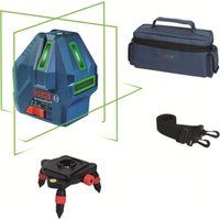


- Product Description and Specifications
- Intended Use
- Product Features
- Technical Data
- Point and line lasers GCL 2-15 GCL 2-15 G
- Fitting
- Inserting/Changing the batteries
- Working with the RM1 rotating mount (see figures A1-A3)
- Operation
- Start-up
- Switching On/Off
- Automatic Shut-Off
- Temporarily Deactivating Automatic Shut-Off
- Setting the Operating Mode
- Automatic Levelling
- Working with Automatic Levelling (see figures B1-E1)
- Working without Automatic Levelling (see figure F1)
- Accuracy Check of the Measuring Tool Influences on Accuracy
- Checking the Height Accuracy of the Horizontal Line
- 22|English
- Checking the Level Accuracy of the Vertical Line
- Checking Plumb Accuracy
- Practical Advice
- Working with the Tripod (Accessory)
- Securing with the universal holder (accessory) (see figure G)
- Working with the Laser Target Plate (see figure G)
- Laser Viewing Glasses (Accessory)
- Example Applications (see figures B2-F2,G and H)
- Maintenance and Servicing
- Maintenance and Cleaning
- After-sales service and advice on using products
- Great Britain
- Ireland
- Australia, New Zealand and Pacific Islands
- Republic of South Africa
- Customer service
- | Français
- Gauteng - BSC Service Centre
- KZN - BSC Service Centre
- Western Cape - BSC Service Centre
- Bosch Headquarters
- Disposal
- Only for EU countries:
- François
- Bortskaffelse
- 80|Norsk
- Avfallshantering
- Stille inn driftsmate
- Epyaia TovTpinoda (eapnma)
- Tepeown me to tniipiyya yevikic xponc (ekaptnma) (BLe n ckova G)
- Epyaia je tv nivaka toxou lezep (bAeTe eikoVa G)
- Tuaia (aεεσouap)
- Tapadeiyama copyoadic (Bene eukovc B2-F2,GkaiH)
- Suvtnponon kal oepic
- Uvtnponn kkaaapiaoc
- Eumnpertnon nearov kaioupoue cepapoyic
- EAAa
- Anoupon
- Móvo yu xópec tnc EE:
- Türkce
- Güvenlik talimati
- Cpok cnyXbI n3dennn
- IpeueeHb KPNTHueckx OTKa3OB H OwH6OuHbIe DeiCTBnepcoHaHa HnN NOnb3OBaTeNa
- Kpntepnnnpedebnbixcoctoannn
- TnH nepnoDnHocb texHHueckoro 06cnyxHBaHHN
- Xpahenne
- TpaHcnpToHpOBka
- 144|Pycckn
- Yka3aHHnNo TexHnke 6e3oNaCHOCTN
- OnncanHe npoodykTa n ycnyr
- PpHMeHeHHe no Ha3HaueHHIO
- H306paXeHHbIe COCTaBHbIe qACTn
- TexHHueckne daHHble
- C6opka
- BCTABKa/3aMeHa6aTapeek
- Pa6ota c noBopOthbIM KpeIeHHem RM1 (cm.pnc.A1-A3)
- Pa60Ta c HcTpymeHTOM
- BklioueHne 3nEkpomHcTpyMeHa
- BkIIOueHne/ByIKIOueHne
- ABTOMATHCCKOEOTKIOUOHeHNE
- BpeMeHHa DeakTHBaunr ABToMaTHueCKOrO ToKlnoueHHa
- yctahOBka pexHmpa60tbi
- KoHTponb ToHOCTH H3MepHTenbHOrO HHCTpyMeHTa
- ΦaKTopb, BmHIOUne Ha ToUHOCTb
- IpoBepKa TOUHOCTn ROpH3OHTaJIbHOJ INHHN NO BbICOTE
- PpOBepKa TOUHOCTH HMBENHPoBaHHa TOpH3OHTaIbHOJHHH
- 150|Pycckn
- IpoBepKa ToUHOCTH HHBENPObAHNBEPTKAnbHOJHHH
- PpOBepka ToHocTHoTBeca
- Yka3aHaHNo pImMeHeHHIO
- Pa6oTa co wTATHBOM (npHnHaIeXHoCTb)
- Pa60Tb C Bn3HpHoM MapKoI (cm.phc.G)
- OuKnIpa6oTbIcIa3epHbIM HnCTpyMeHTOM (npHHaDnExKHOCTb)
- PnHMepeB1 BO3MOXHBIX BnO8 pa6oTbI (CM. pnc. B2-F2, G n H)
- 152|Pycckn
- Texo6cnyxHBaHne n cepBnC
- Texo6cnyxmbahne H ouhctka
- CepBnKoHcyNbTHpOBaHne no BOpocam npmeneHH
- ДяpernoHa:Poccna,Beapycb,KazaxCTan,YkpanHa
- Pocchra
- Benapycb
- Ka3axctan
- MondoBa
- ApMeHHA3ep6aJxH,py3Ha,KnprH3ctan,MOnro- nHa,TaJHKnCTah,TypKMeHNCTah,Y3eKnCTaH
- YtHnHaZna
- TobkoДиЯстан-унhoeBOE C:
- yKpaIHcbka
- Bka3iBKn 3Texhikn 6e3nekn
- MOHTAX
- BCTaBHeHHa/3amHa6atapeHok
- Po6oTa 3 NOBOPOTHM KpinneHHRM1 (INB.MaA1-A3)
- Po6ota
- Touatokpo60TH
- BMnKaHHBmKHaHH
- 156|yKpaHcbKa
- ABTomaTHUHe BHMKahHr
- THMycOBA DeakTHBaui ABTomaTHHOro BHMKaHHA
- BctaHOBneHHpeXmmypo60TH
- ABTomathne HIBeIOBaaHHa
- Po6oTa y pexnmi ABTomathHoro HibenHOaHH (mB. Man. B1-E1)
- Po6ota 6e3 ABToMaTHuHOro HIBeIHOBaHHa (JHB.Man.F1)
- IpebeBipka ToUHOCTI BHMIPHOBAHORIO INCTPymEnta
- ΦaKTOpH, 0o BnINBaHOt b Ha ToHicTh
- 158|YkpaIhcbKa
- Ipebipka tooHocti ropn3oHTanbho iin no Bcotti
- 160|YkpaHcbKa
- IpebeBpKaToUHOcti Bncka
- Bkaizbkn uo do p60tN
- P6oTa3iWtATHBOM (npnnaD)
- Φikcaizra donomoro yhibepcnaBHOKpinneHH (npnnaa) (nB.Man.G)
- Po60TH 3 Bi3npHOo MapkoIO (Hb. Man. G)
- Okynprn dny po60TH 3 na3epom (npnaadn)
- PnKnaI np6oTH (Hb.MaB.B2-F2,GiH)
- Texhiue 06cnyroByBaHHia cepBic
- Texhihe 06cnyrobyaHHn i ouuienHH
- Cepbic i KOHCyNbTauii 3 NHTaHb 3actocvBaHH
- ykpaHa
- Ywni3aui
- Пишдя Край EC:
- Ka3ak
- Eypa3nJ 3KOHOMKaIbIK OdaFbIHa (KeJeH OdaFbHa) Mywe MemLeKeTep aymarfbIHda KOnDaHbInaDbI
- Ohimdi nai danany Mep3imi
- Kb3MeTKeHeme NaDnAHyBHBIN KATENIKTepi MeH icTeH WbIFy Ce6ENTepHHIIMI
- Uekri Kny 6enrinepi
- Kb3MeT Kcpcty Typi MeH Xniniri
- CaRTay
- Tacbimanay
- 162|Kaazak
- Kayinci3ik HycKaynapbi
- Hyktenik neh cblbktbknapep GCL 2-15 GCL 2-15 G
- HNBENHPney ABTOMaTHKacbi
- HnBEnpney ABOtOMaTHKaCbImeH XyMbIC icTey (MbHa cypTepi KapaHb3:B1-E1)
- HnBennpney ABTomathKacbHcbl3 Kymbic icTey (MbHa cypetti kapaHb3:F1)
- Onwey KypabibHbIH dAnirin Tekcepy
- Дандik acepepi
- KoIeHEn cbIbIKtBn6hIKTK dAndirin Tekcepy
- KoIeHeHcIb3bIKTbIH HINBEnHpney dAndiRITekcepy
- 168|Kaazak
- Tik cb3bIKTBH HMBENHPney dAndirin TeKcepii3
- Heri3ri HkyTe dAndiirin TeKcepy
- Painanany HycaynapbI
- UtaTHBneHxymbcictey (kepek-kaapak)
- Omb6an yctafblwnen 6ekitih3 (kepek-kapak) (G cypetih kapaht3
- Ja3ep HbicaHbIK TaKTacbIH naIaIaNHy (MbHa cypETI KapaHbI3:G)
- Ja3ep Kepy Ke3inDipiri (KepeK-Japak)
- XyMbICMbicanapbl(MbHa cypeTepi kapaHb3:B2-F2,GxheH)
- TexHnKaNbIK KyTIm XHe Kbl3MeT
- Kb3MeT Kepcety KaHe Ta3anay
- TytbHybIfa Kbl3Met KOpceTy XHe naJaIaNy KeHecTepi
- Ka3aKCTAH
- Romana
- Kedere kapaTy
- TekKaHaEOeNepiyyin:
- Româna
- Instruetiuni de siguranta
- TexHHueckn daHHN
- MOnTnpaHc
- H3non3BaHe/cmHa Ha 6aTePnnte
- Pa6ota c Bbptnata ce ctoika RM1 (Bx. qnr. A1-A3)
- Pa6ota
- IyckaneBekcnoaatauia
- BkIIOUbaHe Hn3KIOUbaHe
- ABTOMaTHUHO N3KJIIOUBAHe
- BpeMeHHo DeaKTbHpaHe Ha aBTOMaTHHOTO 3KJIIOuBaHe
- №60 npa pexma ha pa60ta
- IpoBepka 3a ToUHOCT Ha H3MepBaTeHnHnHCTpymENT
- ФakTOpH, BnHHeuH Na ToUHOCTTa
- IpoBepKaHaTOUHOCTTaHbBCOHNaHa XOpH30HTANHATA NHHN
- PpOBePKa HtOuHocTtHa HnBEnHpAe Ha XOpN30HTaIIHATA JHHM
- 184|Блларскn
- PpOBepKa HA ToUHocTtHa HnBEnHpAe BbB BeptHKaHnHO HAnpaBneHne
- PpOBepKa Ha ToUHocTHa OTBeca
- Yka3aHn3a pa60Ta
- Pa6oTa cbc tcaTbN (pnpHaIeXhoCT)
- MoHTnpaHe cyHHBepcaJIHATA cToIka (npHHaIeKHOCT) (BXXTe pHr.G)
- Pa6ota c n3aephata MeHrTeHa IIIOa (Bx. fHr. G)
- OuHa 3a Ha6nDaaHe Ha na3epHnaIbU (npHnAaNexKHOCT)
- Pa6oTHn npHmepn(BK. qHr.B2-F2,GnH)
- PpKaHe n cepBn3
- Iopdbpkahe n nouchTaBHe
- KIneHTcKa Cnyk6a H KOHCyIaHr OTHoCHO ynotpe6ata
- Былгаян
- Бракувае
- Cama 3a ctpaHH ot EC:
- MaKeDoHcKn
- Be36eHocn HaONMeHN
- OnncHa npOn3BODOTn nepOpMaHcnte
- YnOTope6a co COoDBeTHa HameHa
- Nnyctpaunja Ha KOMNOHEHTN
- MoHTaxa
- CtBaBbe/MeHyBaBe Ha 6aTepuH
- Pa6oTeHe co poTaunOHnOT dpXkaR M1 (BnDn CnKn A1-A3)
- Ynotpe6a
- CtabaheBoynotpe6a
- BknyyBaBe/HcknyyBaBe
- ABTomaHaHcknyyBahe
- DeakTNBHpabe Ha aBTOMaTHKaTa 3a HCKnyuBaHe
- IpoBepKa Ha ToUHcTa Ha HnBEnHpBe Ha XOpH3OHTaHATA NHHJa
- PpOBepKa Ha ToUHOCTa HA HHBENHPaBeto Ha BepTtKJIHATAIHHJa
- IpoBepKa Ha ToUHocTa Ha NaacepCKnOT ChON
- Cobetn npa6oBeTeO
- 194|MaKeDoHcKn
- Pa6oTehe co cTaMb (onpeMa)
- Pnucpctete co yHnBep3aneH dpXau (onpeMa) (BnH cnka G)
- Pabotebe co zenha Tabna 3a nacepot (Bnncn G)
- Iacepckn 3aunTHn ouHa (onpeMa)
- PpHmepn 3a pa6oTa (BnDn CnKn B2-F2,Gn H)
- OdpKyBaBe H cepBnC
- OdpKyBaBe nHcTeHe
- CepBncha cny6a n COBET npKOpHCTeHe
- MaKeDoHnJa
- OctpaHyBaBe
- Cama 3a 3emjnte oEY:
- Srpski
- Darbs ar stativu (papildiederums)
- Nostiprinasana ar universalā turetaja palidzibu (papildiederums) (attels G)
- Darbs ar lazera merkplaksni (attels G)
- Lazera skatbrilles (papildiederums)
- Darba operaciju piemeri (atteli B2-F2, G un H)
- T
- nannnnnnnnnnnnnnnnnnnn
- yuguaunun
- nTnTnTnTuTnTu
- Su'thai bo
- jbl) RM1 jlgdl Jolal Jdawly Jdll
- (A3-A1gJgJl
- Jusill Egi b
- aai aii
- doJg uall
- auiIg aui
- pIaWlUJluuWlgLaaI a
- JdI I dI
- wJl
- jSjIgUgaaa
- olssjolaiw jIg0
- 1J 1
Brand : BOSCH
Model : GCL 215 Professional
Category : Laser pointer