USER MANUAL GLM 80 Professional BOSCH
YkpaiHcbKa ..CtoPiHa 194
Kaazak. 5er 205
Romana . Pagina 216
BbIrapckn .. CtpaHua 227
MaKeDoHcKn. ..CtpaHnca 238
Srpski Strana 249
Slovenscina Stran 259
All instructions must be read and observed in order for the measuring tool to function safely. The safeguards integrated into the
measuring tool may be compromised if the measuring tool is not used in accordance with these instructions. Never make warning signs on the measuring tool unrecognisable. SAVE THESE INSTRUCTIONS FOR FUTURE
Warning! If operating or adjustment devices other than those specified here are used or other procedures are carried out, this can lead to dangerous exposure to radiation.
The measuring tool is delivered with a warning label (marked in the illustration of the measuring tool on the graphics page with number (20)).
IEC 60825-1:2014 <1 mW, 635 nm

Laser Radiation not stare into beam ass 2 laser product
If the text on the warning label is not in your native language, cover it with the label supplied, which is in your language, before initial commissioning.

Do not direct the laser beam at persons or animals and do not look directly into the laser beam or at its reflection. Doing so could lead to blindless, or could cause acci
dents or damage to the eyes.
If laser radiation hits your eye, you must close your eyes and immediately turn your head away from the beam.
Do not make any modifications to the laser equipment.
Do not use the laser goggles as protective goggles. The laser goggles make the laser beam easier to see; they do not protect you against laser radiation.
Do not use the laser goggles as sunglasses or while driving. The laser goggles do not provide full UV protection and impair your ability to see colours.
Have the measuring tool serviced only by a qualified specialist using only original replacement parts. This will ensure that the safety of the measuring tool is maintained.
Do not let children use the laser measuring tool unsupervised. They could accidentally dazzle someone.
Do not use the measuring tool in explosive atmospheres which contain flammable liquids, gases or dust. Sparks may be produced inside the measuring tool, which can ignite dust or fumes.

Protect the measuring tool against heat, e.g. including prolonged sun exposure, fire, water, and moisture. Danger of explosion.
Do not use the measuring tool with the Micro USB cable connected.
Safety instructions for chargers
This charger is not intended for use by children or persons with physical, sensory or mental limitations or a lack of experience or knowledge. This charger can be used by children aged 8 or older and by persons who have physical, sensory or mental limitations or a lack of experience or knowledge if a person responsible for their safety supervises them or has instructed them in the safe operation of the charger and they understand the associated dangers. Otherwise, there is a risk of operating errors and injuries.
Supervise children during use, cleaning and maintenance. This will ensure that children do not play with the charger.

Do not expose the charger to rain or wet condi
tions. Water entering a power tool will increase the risk of electric shock.
Charge the measuring tool only with the supplied charger.
- Keep the charger clean. Dirt poses a risk of electric shock.
Always check the charger, cable and plug before use. Stop using the charger if you discover any damage. Do not open the charger yourself, and have it repaired only by a qualified specialist using only original replacement parts. Damaged chargers, cables and plugs increase the risk of electric shock.
Do not operate the charger on an easily ignited surface (e.g. paper, textiles, etc.) or in a flammable environment. There is a risk of fire due to the charger heating up during operation.
In case of damage and improper use of the battery, vapours may also be emitted. Ensure the area is well-ventilated and seek medical attention should you experience any adverse effects. The vapours may irritate the respiratory system.
Product Description and Specifications
Intended Use
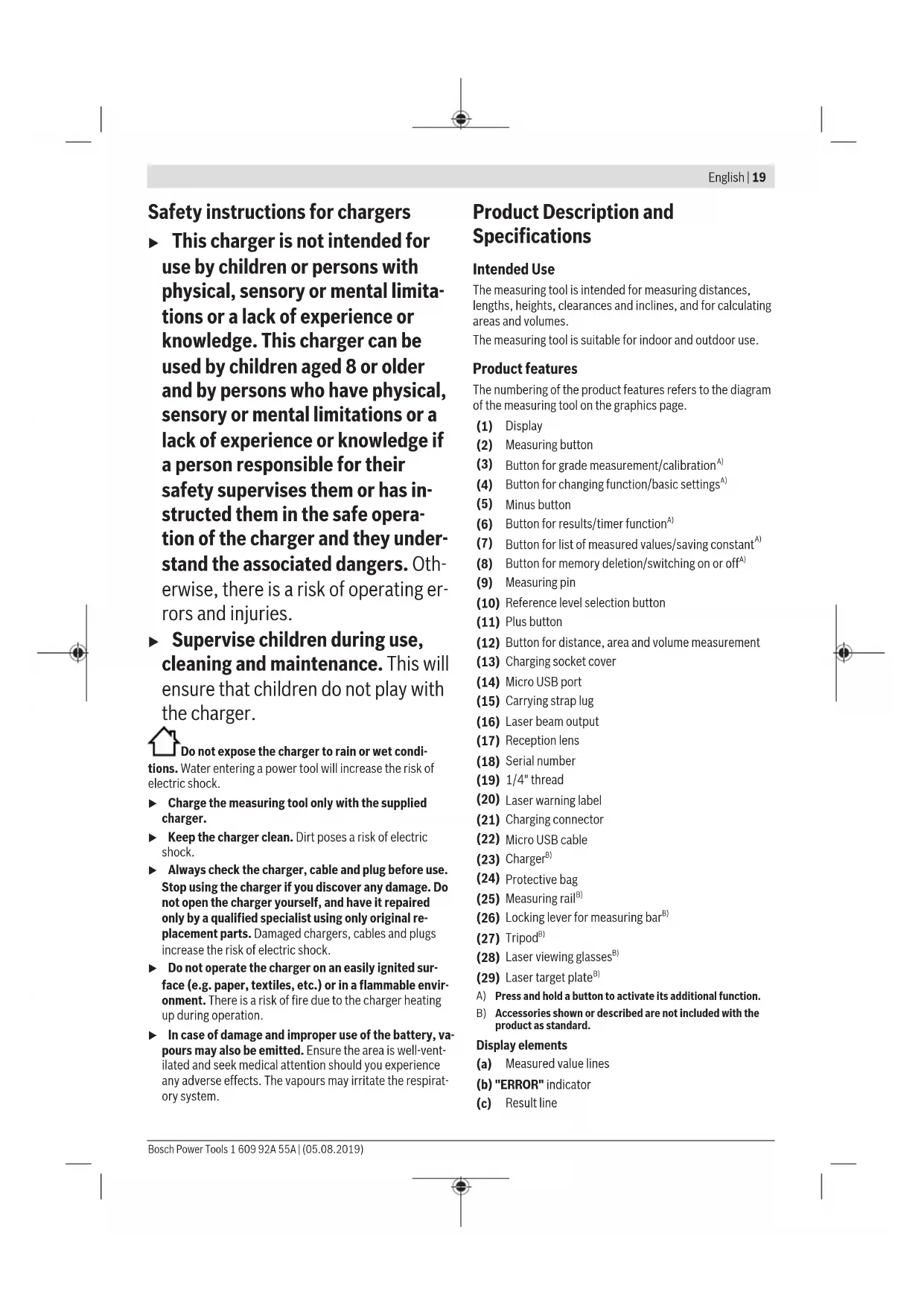
The measuring tool is intended for measuring distances, lengths, heights, clearances and inclines, and for calculating areas and volumes.
The measuring tool is suitable for indoor and outdoor use.
Product features
The numbering of the product features refers to the diagram of the measuring tool on the graphics page.
(1) Display
(2) Measuring button
(3) Button for grade measurement/calibration
(4) Button for changing function/basic settings
(5) Minus button
(6) Button for results/timer function
(7) Button for list of measured values/saving constant
(8) Button for memory deletion/switching on or off
(9) Measuring pin
(10) Reference level selection button
(11) Plus button
(12) Button for distance, area and volume measurement
(13) Charging socket cover
(14) Micro USB port
(15) Carrying strap lug
(16) Laser beam output
(17) Reception lens
(18) Serial number
(19) 1 / 4'' thread
(20) Laser warning label
(21) Charging connector
(22) Micro USB cable
(23) Charger81
(24) Protective bag
(25) Measuring rail
(26) Locking lever for measuring bar
(27) Tripod
(28) Laser viewing glasses
(29) Laser target plate
A) Press and hold a button to activate its additional function.
B) Accessories shown or described are not included with the product as standard.
Display elements
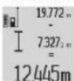
(a) Measured value lines
(b) "ERROR" indicator
(c) Result line
20|English
(d) Digital spirit level/position of measured value list entry
(e) Indicator for measured value list
(f) Measuring functions
Length measurement
Area measurement
Volume measurement
Continuous measurement
Indirect height measurement
Double indirect height measurement
Indirect length measurement
Timer function
Wall area measurement
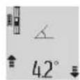
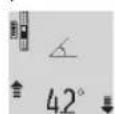
Grade measurement
(g) Battery charge indicator
(h) Laser switched on
(i) Reference level of measurement
(j) Temperature warning
Technical data
Digital laser measure GLM 80 GLM 80+R 60
| Article number | 3601 K72 3.. 3601 K72 3.. |
| Distance measurement | | |
| Measuring range (typical) 0.05-80 m | A) | 0.05-80 mA) |
| Measuring range (typical, unfavourable conditions) 35 m | B) | 35 mB) |
| Measuring accuracy (typical) ± 1.5 mm | A) | ± 1.5 mmA) |
| Measuring accuracy (typical, unfavourable conditions) ±2.5 mm | B) | ±2.5 mmB) |
| Smallest display unit 0.1 mm 0.1 mm | | |
| Indirect distance measurement and level | | |
| Measuring range -60° to +60° -60° to +60° | | |
| Grade measurement | | |
| Measuring range 0°-360° (4 x 90°) | C) | 0°-360° (4 x 90°)C) |
| Measuring accuracy (typical) 0.2° | D) E) | ±0.2°D)E) |
| Smallest display unit 0.1° 0.1° | | |
| General | | |
| Operating temperature -10 °C to +50 °C | F) | -10 °C to +50 °CF) |
| Storage temperature | -20 °C to +50 °C | -20 °C to +50 °C |
| Permitted charging temperature range | +5 °C to +40 °C | +5 °C to +40 °C |
| Max. relative air humidity | 90% | 90% |
| Max. altitude | 2000 m | 2000 m |
| Pollution degree according to IEC 61010-1 | 2G) | 2G) |
| Laser class | 2 | 2 |
| Laser type | 635 nm, < 1 mW | 635 nm, < 1 mW |
| Laser beam diameter (at 25 °C) approx. | | |
| - 10 m distance | 6 mmE) | 6 mmF) |
| - 80 m distance | 48 mmE) | 48 mmF) |
| Adjustment accuracy of the laser to the housing approx. | | |
| - Vertical | ±2 mm/mH) | ±2 mm/mH) |
| - Horizontal | ±10 mm/mH) | ±10 mm/mH) |
| Automatic switch-off after approx. | | |
| - Laser | 20 s | 20 s |
| - Measuring tool (without measurement) | 5 min | 5 min |
| Weight according to EPTA-Procedure 01:2014 | 0.14 kg 0.14 kg | |
| Dimensions | 51 x 111 x 30 mm | 51 x 111 x 30 mm |
Digital laser measure GLM 80 GLM 80+R 60
Protection rating IP 54 (dust and splash-proof) IP 54 (dust and splash-proof)
Measuring rail
| Article number - | | 3601 K79 000 |
| Dimensions - 58 x 610 x 30 mm | | |
| Battery Li-ion Li-ion | | |
| Rated voltage 3.7 V 3.7 V | | |
| Capacity 1.25 Ah 1.25 Ah | | |
| Number of battery cells 1 1 | | |
| Individual measurements per battery charge approx. 25000 | 1) | 250001) |
| Charger | | |
| Article number | 2609 120 7.. | 2609 120 7.. |
| 1600 A01 3.. | 1600 A01 3.. |
| Charging time | approx. 3 h | approx. 3 h |
| Battery charging voltage | 5.0V-5.0V | == |
| Charge current | 1000 mA | 1000 mA |
| Protection class | ☐/II | ☐/II |
A) For measurements from the front edge of the measuring tool, 100% reflectivity of the target (e.g. a white wall), weak backlighting and 25^ operating temperature. In addition, a deviation influence of ± 0.05 ~mm / m needs to be taken into account.
B) For measurements from the rear edge of the measuring tool, 10 - 100% reflectivity of the target, strong backlighting and 25^ operating temperature. In addition, a deviation influence of ± 0.29mm / m needs to be taken into account.
C) For measurements that use the back of the device as a reference, the max. measuring range amounts to ± 60^
D) After calibration in accordance with figure H. Additional pitch error of ± 0.01^ /degree up to 45^ .
E) The width of the laser line depends on the surface characteristics and on the ambient conditions.
F) In continuous measurement mode, the max. operating temperature is +40^ .
G) Only non-conductive deposits occur, whereby occasional temporary conductivity caused by condensation is expected.
H)At 25^
1) For a new and charged battery without display illumination and sound.
The serial number (18) on the type plate is used to clearly identify your measuring tool.
Please observe the article number on the type plate of your battery charger. The trade names of individual battery chargers may vary.
Initial start-up
Charging the battery
Use only the chargers listed in the technical data. Only these chargers are matched to the lithium-ion battery of your measuring tool.
The use of chargers from other manufacturers can lead to defects on the measuring tool; a higher voltage (e.g. 12 V) from a vehicle charger is not suitable for charging this measuring tool. The warranty is rendered void if these instructions are not followed.
Pay attention to the mains voltage. The voltage of the power source must match the voltage specified on the rating plate of the charger.
Note: The battery is supplied partially charged. To ensure full capacity of the battery, completely charge the battery before the first use.
The lithium-ion battery can be charged at any time without reducing its service life. Interrupting the charging process does not damage the battery.
If the lower segment of the battery charge indicator (g) flashes, only a few more measurements can be made. Charge the battery.
If the frame around the segments of the battery charge indicator (g) flashes, no more measurements are possible. The measuring tool can only be used for a short time (e.g. to check entries in the measured value list). Charge the battery.
Connect the measuring tool to the charger (23) using the micro USB cable (22) provided. Plug the charger (23) into the socket. The charging process will begin.
The battery charge indicator (g) indicates the charging progress. The segments flash successively during charging. When all segments of the battery charge indicator (g) are displayed, the battery is fully charged. If you are not planning to use the power tool again soon, dis connect the charger from the mains.
The battery can also be charged at a USB port. To do so, connect the measuring tool to a USB port using the micro USB cable. In USB mode (charging mode, data transfer), the charging time can be noticeably longer.
22 | English
The measuring tool cannot be used during the charging procedure.
Protect the charger against moisture.
Recommendations for optimal handling of the battery in the measuring tool
Only charge the measuring tool in the permissible temperature range, (see "Technical data", page 20). As an example, do not leave the measuring tool in a vehicle during the summer.
A significantly reduced operating time after charging indicates that the battery has deteriorated and must be replaced by the Bosch after-sales service.
Follow the instructions on correct disposal.
Operation
Start-Up
Protect the measuring tool from moisture and direct sunlight.
Do not expose the measuring tool to any extreme temperatures or variations in temperature. For example, do not leave it in a car for extended periods of time. In case of large variations in temperature, allow the measuring tool to adjust to the ambient temperature before putting it into operation. The precision of the measuring tool may be compromised if exposed to extreme temperatures or variations in temperature.
Avoid substantial knocks to the measuring tool and avoid dropping it. Always carry out an accuracy check before continuing work if the measuring tool has been subjected to severe external influences (see "Checking accuracy and calibrating the grade measurement (see figure H)", page 26) and (see "Accuracy check of the distance measurement", page 26).
Switching on/off
Never leave the measuring tool unattended when switched on, and ensure the measuring tool is switched off after use. Others may be dazzled by the laser beam.
The following options are available for switching on the measuring tool:
- Pressing the on/off button (8): The measuring tool is switched on in the length measurement function. The laser is not switched on.
- Pressing the measuring button (2): Measuring tool and laser are switched on. The measuring tool will be in the length measurement function. When the measuring tool is inserted in the measuring rail (25), the grade measurement function is activated.
Do not direct the laser beam at persons or animals and do not stare into the laser beam yourself (even from a distance).
To switch off the measuring tool, press and hold the on/off button (8).
If no button on the measuring tool is pressed for approx. five minutes, then the measuring tool will automatically switch itself off to preserve battery life.
If the angle has not been changed for approx. five minutes while the measuring tool is in the "grade measurement" operating mode, the tool will automatically switch itself off to preserve battery life.
All saved values are retained when the tool is automatically switched off.
Measuring process
After the measuring tool has been switched on by pressing the measuring button (2), the tool is always in the length measurement function by default, or in the grade measurement function if the tool has been inserted into the measuring rail (25). Other measuring functions can be switched to by pressing the respective function button (see "Measuring functions", page 23).
Once the measuring tool has been switched on, the rear edge of the measuring tool is selected as the reference level for measurement. You can change the reference level by pressing the reference level selection button(10) (see "Selecting the reference level (see figure A)", page 22).
Apply the measuring tool with the selected reference level to the point at which you want to start the measurement (e.g. wall).
To switch on the laser beam, briefly press the measuring button (2).
- Do not direct the laser beam at persons or animals and do not stare into the laser beam yourself (even from a distance).
Aim the laser beam at the target surface. To initiate the measurement, briefly press the measuring button (2) again. While the laser beam is continuously switched on, measurement will begin after the first press of the measuring button (2). In the continuous measurement function, measurement begins as soon as the function is activated.
The measured value typically appears within 0.5 seconds and no later than 4 seconds. The duration of the measurement depends on the distance, the lighting conditions and the reflective properties of the target surface. The end of the measurement is indicated by an audio signal. Upon completion of the measurement, the laser beam is automatically switched off.
If no measurement has been performed within approx. 20 seconds of aim being taken, the laser beam is switched off automatically to preserve battery life.
You can choose between four different reference levels for the measurement:
The rear edge of the measuring tool or the front edge of the measuring pin (9) when it has been folded out by 90^ (e.g. when applying the tool to outer corners)
The tip of the measuring pin (9) when it has been folded 180^ (e.g. when measuring from a corner)
- The front edge of the measuring tool (e.g. when measuring from a table edge)
The centre of the thread (19) (e.g. for tripod measurements)
To select the reference level, press the button (10) until the required reference level is shown on the display. The rear edge of the measuring tool is pre-set as the reference level every time the measuring tool is switched on.
It is not possible to make a retrospective alteration to the reference level for measurements that have already been taken (e.g. when displaying measured values in the measured value list).
To enter the basic settings menu, press and hold the button for basic settings (4).
Briefly press the basic settings button (4) to select the individual menu items.
Press the minus button (5) or the plus button (11) to select the setting within the menu items.
To exit the basic settings menu, press the measuring button (2).
| Basic settings |
| Audio signals On | Off |
| Off |
| Display illumination On | Off |
| Off |
| Automatically on/off |
| Digital spirit level On | Off |
| Off |
| Display rotation On | Off |
| Off |
| Continuous laser beam On | Off |
| Off |
| Unit of distance (depending on country version) | m, ft, inch, etc. |
| Unit for angle (depending on country version) | °, %, mm/m, inch/ft |
All basic settings except for the continuous laser beam setting are saved when switching off the tool.
Continuous laser beam
Do not direct the laser beam at persons or animals and do not stare into the laser beam yourself (even from a distance).
In this setting, the laser beam remains switched on even between measurements; measurement simply requires one brief press of the measuring button (2).
Measuring functions
Simple length measurement
For length measurements, repeatedly press the button (12) until the indicator for length measurement Jappears on the display.
Briefly press the measuring button (2) once to switch on the laser and once to measure. The measured value is displayed in the result line (c).
For multiple consecutive length measurements, the results of the last measurements are shown in the measured value lines (a).
Area measurement
For area measurements, repeatedly press the button (12) until the indicator for area measurement appears on the display.
Then measure the width and length one after the other as with a length measurement. The laser beam remains switched on between the two measurements.
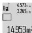
Once the second measurement has been completed, the area is automatically calculated and displayed in the result line (c). The individual measured values can be found in the measured value lines (a).
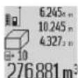
Volume measurement
For volume measurements, repeatedly press the button (12) until the indicator for volume measurement appears on the display.
Then measure the width, length and depth one after the other as with a length measurement. The laser beam remains switched on between the three measurements.
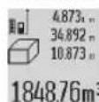
Once the third measurement has been completed, the volume is automatically calculated and displayed in the result line (c). The individual measured values can be found in the measured value lines (a).
Values over 999,999 m³ cannot be displayed; "ERROR" will instead appear on the display. Divide the volume to be measured into individual measurements, the resulting values of which you can calculate separately and then combine into an overall total.
In continuous measurement mode, the measuring tool can be moved relative to the target, during which the measured value will be updated every half a second. You can, for ex
24|English
ample, move a desired distance away from a wall while reading off the current distance at all times.
For continuous measurements, repeatedly press the button for changing function (4) until the indicator for continuous measurement appears on the display. To start the continuous measurement, press the measuring button (2).
The minimum measurement is used to determine the shortest distance from a fixed reference point. For example, it can help in determining verticals or horizontals.
The maximum measurement is used to determine the greatest distance from a fixed reference point. For example, it can help in determining diagonals.
The current measured value is shown in the result line (c). The maximum ("max") and minimum ("min") measured value appear in the measured value lines (a). It is then always
overwritten if the current length measurement
value is smaller or larger than the previous minimum or maximum value.
Press the memory deletion button (8) to erase the previous minimum or maximum values.
Press the measuring button (2) to end the continuous measurement. The last measured value is displayed in the result line (c). Pressing the measuring button (2) again starts a new continuous measurement.
Continuous measurement automatically switches off after five minutes. The last measured value remains displayed in the result line (c).
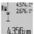
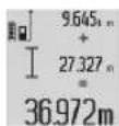
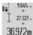
Indirect distance measurement
The indirect distance measurement is used to determine distances that cannot be measured directly, due to an obstacle that would impede the path beam or the absence of a target surface that could serve as a reflector. This measuring procedure can only be employed vertically. Any horizontal deviation will lead to measurement errors.
The laser beam remains switched on between the individual measurements.
For indirect length measurements, three measuring modes are available. Each measuring mode can be used for determining different distances.
Repeatedly press the button for changing function (4) until the indicator for indirect height measurement appears on the display.
Ensure that the measuring tool is at the same height as the lower measuring point. Then tilt the measuring tool around the reference level and measure distance (1) as for a length measurement.
Once the measurement is complete, the result for the required distance "X" is displayed in the result line (c). The measured values for distance "1" and angle "a" can be found in the measured value lines (a).
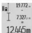
Repeatedly press the button for changing function (4) until the indicator for double indirect height measurement appears on the display.
Measure distances 1 and 2 in succession as for a length measurement.
Once the measurement is complete, the result for the required distance X is displayed in the result row (c). The measured values for distances 1 and 2 and angle can be found in the measured value rows (a).
Ensure that the reference level for the measurement (e.g. the rear edge of the measuring tool) remains in exactly the same place for all the individual measurements in a single measuring process.
Repeatedly press the button for changing function (4) until the indicator for indirect length measurement appears on the display.
Ensure that the measuring tool is at the same height as the required measuring point. Then tilt the measuring tool around the reference level and measure distance "1" as for a length measurement.
Once the measurement is complete, the result for the required distance "X" is displayed in the result line (c). The measured values for distance "1" and angle "a" can be found in the measured value lines (a).
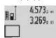
The wall area measurement is used to determine the sum of multiple individual areas with a common height.
In the illustrated example, the total area of several walls that have the same ceiling height A but different lengths B is to be determined.
For wall area measurements, repeatedly press the button for changing function (4) until the indicator for wall area measurement appears on the display.
Measure the ceiling height A as with a length measurement. The measured value ("cst") is displayed in the top measure value line (a). The laser remains switched on.
Then measure the length B_1 of the first wall. The area is automatically calculated and displayed in the result line (c). The last measured value for length can be found in the middle measured value line. (a). The laser remains
switched on.
Now measure the length B_2 of the second wall. The individual measured value displayed in the middle measured value line (a) is added to the length B_1 . The sum of the two lengths ("sum", displayed in the bottom measured value line
(a)) is multiplied by the saved height A. The total area value is displayed in the result line (c).
You can measure any number of lengths B_x , which will be automatically added and multiplied by the height A .
The requirement for a correct area calculation is that the first measured length (for example the ceiling height A) is identical for all sub-areas.
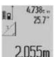
Press the button for grade measurement (3) to bring up the indicator for grade measurement on the display. The rear of the measuring tool serves as the reference level. Press the button for grade measurement (3) again to use the sides of the measuring tool as a reference level and rotate the display view by 90^ .
Press the measuring button (2) to fix the measured value and transfer it to the measured value memory. Press the measuring button (2) again to continue the measurement. If the display flashes during measurement, the measuring tool has been tipped too heavily to the side.
If the "digital spirit level" function is activated in the basic settings, the grade value is also displayed in the other measuring functions in line (d) of the display (1).
Timer function
The timer function is useful when the measuring tool should be kept stationary during measurement, for example. Press and hold the button for the timer function (6) to bring up the indicator on the display.
The time period between triggering the timer and starting measurement is displayed in the measured value line (a). The time period can be set between 1-60 seconds by pressing the plus button (11) or minus button (5).
The measurement is made automatically after the set time period has expired.
The timer function can also be used for distance measurements within other measuring
functions (e.g. area measurement). It is not possible to add or subtract measuring results or carry out continuous measurement.
List of the last measured values
The measuring tool stores the last 20 measured values and their calculations and displays them in reverse order (with the most recent measured value displayed first).
To retrieve the saved measurements, press the button (7). The result of the last measurement appears on the display, along with the indicator for the measured values list (e) and with storage space for the numbering of the dis
played measurements.
If no further measurements are saved upon pressing the button (7) again, the measuring tool switches back to the last measuring function. Press one of the buttons for the measuring functions to exit the list of measured values.
To permanently save the currently displayed measured length value as a constant, press and hold the button for the list of measured values (7) until "CST" is shown on the display. An entry in the list of measured values cannot be retrospectively saved as a constant.
To use a measured length value in a measuring function (e.g. area measurement), press the button for the list of meas
ured values (7), select the desired entry and confirm it by pressing the results button (6).
Deleting measured values
Briefly pressing the button (8) will delete the last measured value in all measuring functions. Repeatedly pressing the button briefly will delete the individual measured values in reverse order.
To delete the currently displayed entry in the list of measured values, briefly press the button (8). To delete the complete list of measured values and the constant "CST", press and hold the measured value list button (7) and at the same time briefly press the button (8).
In the wall area measurement function, a brief first press of the button (8) will delete the last individual measured value; a second press will delete all lengths B_x ; a third will delete the ceiling height A.
Adding measured values
To add measured values together, first perform any measurement or select an entry from the list of measured values. Next, press the plus button (11). "+" will appear on the display as confirmation. Then perform a second measurement or select another entry from the measured value list.
Press the results button (6) to retrieve the sum of both measurements. The calculation is shown in the measured value lines (a) and the sum is displayed in the result line (c).
When the sum has been calculated, you can add more measured values or measured value list entries to this result if you press the plus button (11) before each measurement. Press the results button (6) to end the addition.
Information on addition:
-
Mixtures of length, area and volume values cannot be added together. For example, if a length value and an area value are added together, "ERROR" will appear briefly on the display when the results button (6) is pressed. The measuring tool will then switch back to the most recently active measuring function.
-
The result of a measurement (e.g. volume value) is always added; for continuous measurements, the measured value displayed in the result line (c) is added. It is not possible to add individual measured values from the measured value lines (a).
Subtracting measured values
To subtract measured values, press the minus button (5); "-" will appear on the display as confirmation. The subsequent steps are the same as for the "Adding measured values" section.
Practical advice
General advice
The reception lens (17) and the laser beam output (16) must not be covered during the measuring process.
The measuring tool must not be moved during a measurement (with the exception of the continuous measurement
26|English
and grade measurement functions). For this reason, place the measuring tool against or on a firm surface whenever possible.
Influences on the measuring range
The measuring range depends on the lighting conditions and the reflective properties of the target surface. For better visibility of the laser beam when working outdoors and in bright sunlight, use the laser viewing glasses (28) (accessory) and the laser target plate (29) (accessory) or shade the target area.
Influences on the measurement result
Due to physical effects, the possibility of inaccurate measurements when measuring various surfaces cannot be excluded. These include:
- Transparent surfaces (e.g. glass, water)
- Reflective surfaces (e.g. polished metal, glass)
- Porous surfaces (e.g. insulating materials)
- Structured surfaces (e.g. roughcast, natural stone).
If necessary, use the laser target plate (29) (accessory) on these surfaces.
Inaccurate measurements are also possible where the laser is pointed at target surfaces diagonally.
Layers of air at different temperatures and indirectly received reflections can also influence the measured value.
Regularly check the accuracy of the grade measurement.
This is accomplished by means of a reverse measurement. To do this, lay the measuring tool on a table and measure the inclination. Turn the measuring tool by 180^ and measure the inclination again. The difference between the displayed values must not exceed 0.3^ .
In case of greater deviation, the measuring tool must be recalibrated. To do this, press and hold the grade measurement button (3). Follow the directions on the display.
Accuracy check of the distance measurement
You can check the accuracy of the measuring tool as follows:
-
Choose a measuring section of approx. 1 - 10m in length that is permanently unchanged, the exact length of which is known to you (e.g. room width, door opening). The measuring section must be indoors, and the target surface of the measurement must be smooth and reflect well.
-
Measure the section ten times in succession.
The deviation between the individual measurements and the mean value must not exceed ± 2mm . Record the measurements in order to be able to compare the accuracy later on.
Working with the tripod (accessory)
The use of a tripod is particularly necessary for larger distances. Place the measuring tool with the 1/4'' thread (19) on the quick-release plate of the tripod (27) or a conventional camera tripod. Tighten it using the locking screw of the quick-release plate.
Set the reference level for measurements with a tripod by pressing the button (10) accordingly (thread reference level).
The measuring rail (25) can be used for a more exact grade measurement result. Distance measurements are not possible with the measuring rail.
Insert the measuring tool into the measuring rail (25) as shown and lock the measuring tool in place with the locking lever (26). Press the measuring button (2) to activate the "measuring rail" operating mode.
Regularly check the accuracy of the grade measurement by means of a reverse measurement or the levels on the measuring rail.
In case of greater deviation, the measuring tool must be recalibrated. To do this, press and hold the grade measurement button (3). Follow the directions on the display.
To end the "measuring rail" operating mode, switch off the measuring tool and remove it from the measuring rail.
Errors - Causes and Corrective Measures
Cause Corrective measures
Temperature warning(j) flashes, measurement not possible.
The measuring tool is outside Wait until the measuring tool the operating temperature of has reached operating tem- 10^ to +50^ (in the con- perature. tinuous measurement func tion, up to +40^)
Display shows "ERROR"
Addition/subtraction of measured values with different units of measurement. Only add/subtract measured values with the same units of measurement.
Angle between laser beam and target is too acute. Increase the angle between the laser beam and the target
Target surface is too reflective (e.g. mirror) or not reflective enough (e.g. black material), or ambient light is too bright. Use the laser target plate (29).
The laser beam output (16) Wipe the laser beam output and/or reception lens (17) (16) and/or reception lens are fogged up (e.g. due to a rapid temperature change).
Calculated value is larger than 999,999 m/m²/m³. Divide the calculation into intermediate steps.
Display shows >60^ or -60^
The grade measuring range Perform the measurements for the measuring function or within the specified angle reference level has been ex- range.
ceeded.
Display shows "CAL" and "ERROR"
Cause Corrective measures
The calibration of the grade Repeat the calibration ac measurement has not been according to the instructions carried out in the right order that appear on the display or has not been carried out in and in the manual. the correct positions.
| The surfaces used for calib-ration were not precisely ho- rizontaI or vertical. | Repeat the calibration on a horizontal or vertical surface and check the surfaces be- forehand if necessary using a spirit level. |
| The measuring tool has moved or tilted when the button was pressed. | Repeat the calibration and hold the measuring tool still against the surface when pressing the button. |
Battery charge indicator (g), temperature warning (j) and "ERROR" shown in the display
The temperature of the Wait until the charging temmeasuring tool is outside the perature range has been permissible charging temper- reached.
ature range.
Battery charge indicator (g) and "ERROR" shown in the display
| The battery charging voltage is not correct. | Check whether the connection has been established correctly and that the micro USB cable is working properly. If the device symbol flashes, the battery is defective and must be replaced by the Bosch after-sales service. |
Battery charge indicator (g) and clock symbol (f) shown in the display
Charging time significantly Only use the original Bosch extended due to the charging micro USB cable. current being too low.
Measurement result implausible
Target surface reflection not Cover the target surface. distinct (e.g. water, glass).
Laser beam output (16) and/ or reception lens (17) are (16) and/or reception lens covered. (17) clear.
An incorrect reference level Select a reference level that has been set. is appropriate for the measurement.
Obstruction in the path of the The laser point must be fully laser beam. on the target surface.
The indicator remains unchanged or the measuring tool reacts unexpectedly when a button is pressed.
Software error. Press the measuring button
(2) and the button for memory deletion/switching
Cause Corrective measures
on or off (8) to reset the software.
The measuring tool monitors correct functioning in every measurement. If a defect is detected, the display will indicate only the symbol shown opposite. In this case, or if the above-mentioned corrective measures cannot rectify
an error, submit the measuring tool to the Bosch after-sales service via your dealer.
Maintenance and Service
Maintenance and Cleaning
Only store and transport the measuring tool in the protective bag provided.
Keep the measuring tool clean at all times.
Never immerse the measuring tool in water or other liquids. Wipe off any dirt using a damp, soft cloth. Do not use any detergents or solvents.
Take particular care of the reception lens (17), which must be handled with the same level of care you would give to a pair of glasses or a camera lens.
If the measuring tool needs to be repaired, send it off in the protective bag (24).
After-Sales Service and Application Service
Our after-sales service responds to your questions concerning maintenance and repair of your product as well as spare parts. You can find explosion drawings and information on spare parts at: www.bosch-pt.com
The Bosch product use advice team will be happy to help you with any questions about our products and their accessories.
In all correspondence and spare parts orders, please always include the 10-digit article number given on the nameplate of the product.
Great Britain
Robert Bosch Ltd. (B.S.C.)
P.O.Box 98
Broadwater Park
North Orbital Road
Denham Uxbridge
UB95HJ
At www.bosch-pt.co.uk you can order spare parts or arrange the collection of a product in need of servicing or repair.
Tel. Service: (0344) 7360109
E-Mail: boschservicecentre@bosch.com
Ireland
Origo Ltd
Unit 23 Magna Drive
Magna Business Park
City West
Dublin 24
Tel. Service: (01) 4666700
Fax: (01) 4666888
28 | Français
Australia, New Zealand and Pacific Islands
Robert Bosch Australia Pty. Ltd.
Power Tools
Locked Bag 66
Clayton South VIC 3169
Customer Contact Center
Inside Australia:
Phone: (01300) 307044
Fax: (01300) 307045
Inside New Zealand:
Phone: (0800) 543353
Fax: (0800) 428570
Outside AU and NZ:
Phone: +61 3 95415555
www.bosch-pt.com.au
www.bosch-pt.co.nz
Republic of South Africa
Customer service
Hotline: (011) 6519600
Gauteng - BSC Service Centre
35 Roper Street, New Centre
Johannesburg
Tel.: (011) 4939375
Fax: (011) 4930126
E-Mail: bsctools@icon.co.za
KZN - BSC Service Centre
Unit E, Almar Centre
143 Crompton Street
Pinetown
Tel.: (031) 7012120
Fax: (031) 7012446
E-Mail: bsc.dur@za.bosch.com
Western Cape - BSC Service Centre
Democracy Way, Prosperity Park
Milnerton
Tel.: (021) 5512577
Fax: (021) 5513223
E-Mail: bsc@zsd.co.za
Bosch Headquarters
Midrand, Gauteng
Tel.: (011) 6519600
Fax: (011) 6519880
E-Mail: rbsa-hq.pts@za.bosch.com
Armenia, Azerbaijan, Georgia
Robert Bosch Ltd.
David Agmashenebeli ave. 61
0102 Tbilisi, Georgia
Tel. +995322510073
www.bosch.com
Kyrgyzstan, Mongolia, Tajikistan, Turkmenistan, Uzbekistan
TOO "Robert Bosch" Power Tools, After Sales Service
Muratbaev Ave., 180
050012, Almaty, Kazakhstan
Service Email: service.pt.ka@bosch.com
Official Website: www.bosch.com, www.bosch-pt.com
Transport
The contained lithium-ion batteries are subject to the Dangerous Goods Legislation requirements. The batteries are suitable for road-transport by the user without further restrictions.
When shipping by third parties (e.g.: by air transport or forwarding agency), special requirements on packaging and labelling must be observed. For preparation of the item being shipped, consulting an expert for hazardous material is required.
Disposal

Measuring tools, chargers, batteries, accessories and packaging should be recycled in an environmentally correct manner.

Do not dispose of measuring tools, chargers or batteries with household waste.
Only for EU countries:
According to the Directive 2012/19/EU, measuring tools and chargers that are no longer usable, and, according to the Directive 2006/66/EC, defective or used battery packs/batteries must be collected separately and disposed of in an environmentally correct manner.
Battery packs/batteries:
Li-ion:
Please observe the notes in the section on transport (see "Transport", page 28).
Integrated batteries may only be removed for disposal by qualified personnel. Opening the housing shell can destroy the measuring tool.
Before you can remove the battery from the measuring tool, you will need to use the measuring tool until the battery is completely discharged. Unscrew the screws on the housing and remove the housing shell in order to remove the battery. To prevent a short circuit, disconnect the connectors on the battery one at a time and then isolate the poles. Even when fully discharged, the battery still contains a residual capacity, which can be released in case of a short circuit.
François
Robert Bosch (France) S.A.S.
Calle Robert Bosch No. 405
C.P. 50071 Zona Industrial, Toluca - Estado de Mexico
Tel.: (52) 55 528430-62
Tel.: 800 6271286
Bosch Service Center
Telegravej 3
2750 Ballerup
Pá www.bosch-pt.dk kan der online bestilles reservedele el-ler oprettes en reparations ordre.
TIf. Service Center: 44898855
Fax:44898755
E-Mail: vaerktoej@dk.bosch.com
Transport
Laser Radiation Do not stare into beam Class 2 laser product
Addition ay matvarden
For att lagga till matvarden, utfor forst en valfri matning ell er valj en inmatning fran matvardeslistan. Tryck sedan popluskappen (11). I displayen visas ^ 喜 som bekraltelse. Utfor sedan an andra matning ell valj ett ytterligare inforande ur matvardeslistan.
For att visa summan for bada matningar, tryck pa resultatknappen (6). Berakningen visas i matvardesraderna (a), summan stari resultatraden (c).
Bosch Service Center
Telegrafvej 3
2750 Ballerup
Danmark
Tel.: (08) 7501820 (inom Sverige)
Fax: (011) 187691
Transport
De litiumjonbatterier som ingar ar underkastade kraven for farligt gods. Anvandaren kan utan ytterligare forpliktelser transportera batterierna pa allman vag.
Laser Radiation Do not stare into beam Class 2 laser product
EAV TO KEIevo TNC PPOeIOBOnuTnKc IVaKiBaC DEV Eiiv Otn YAwOoA TNC XwPac OAC, Tore Npv Tn Theon VIA Ipnwn Fopad OE Aetoupyia KOLAnote NaW To Oumnapadoboevo autokoAAnTo OTN YAwOoA TNC XwPac OAc.

Mny kateuovete nTv akltva lecp naw o npowna n Zwa ka mny koutae ot lioi kateuoeiav ony apeon ny avakawevn aktiva lezep. 'Eto mnopei va Tupawote
aToja,va npokaleoete atuxmuata n va lambdaeTe ta maia oac.
2e nepintwnnou nakriva laeepneoe ra maia oac, npenei va klaieoetra paia ouveidnta kalva anopakpuvetotekepaiaocaeowc anyakrtiva.
Mnpojeiree kaiaaayn otduatan letcep.
Mn xpnoponoieTe yuaia alecep wc npootateutka yuaia. Ta yuaia alecep xnpoueouv ia tvn kalutepn avaywopian tnc aktivac alecep, aaaa oupc dev npootateouv ano tvn aktiva alecep.
Mn xnpoioeTe ta yuaia leiep w yuaia nAlou n Otv obukkukopopia. Ta yuaia leiep dev npooepovu npno npootaia an Tnv unepw6n aktivobolia kai peiwovu Tnv avriany Tcw xpawatv.
Avaote TmV emakeun Tou opyavou meponnc mpo o ce 6kepuevo texviko npoosnko kalmoe yviia avtaalakka. M' autov tov tpno Egaopaaizetai n diatnpnon tnc aaaalouc aeitoupyiac tou epaaleiou metpnonc.
Mny aphiote naia dxwipc emtnponn va xpnaonououov to opyavo mepnonnc leiep. Ta umopouav akoua va tuapawouv atopa.
Mny epyaeote me to opyavo metpnoanoe nukivduvo yia ekpnn nepiabllov, oto onio biakovtaeupknta uypa, aepia n eupkntcscokvec.20eotepiko tou epyaleiou metpnoancmuopei va dnmuopyntheta anivnpiaoocki etoi va avaplexouv ngokovn navaohuaieic.

IpootateoTo opyavo mepnonc ano 0eipota, n. x. akoun kal ano ouvexn nlaikn aktivofoia, foTia, vepo kal
yopaia.Ynpexi kivouoc eKpnn
Mn xnpaonoeire to opyavo metponnc me ouv6e6evo to kalwio Micro-USB.
YnoBcicacaaaleiacyiaopptotec
(14)Yn06ox Micro-USB
(15) Ynbooxi kopboviou eTaapopac
(16) 'E\xo0dc akrivac
(17)Φakocλnμns
(18) ApiOoC oepaC
(19) Σπειρωμα 1/4"
(20) Pioe16oioiTkn nivakiδa λεiερ
(21) c o n
(22) Kaλδισι Micro-USB
(23)ΦoPTIOIa
(24) TódvTnpooTaiaC
(25) Páγa μέτρησις81
(26) MoXloC aOpaAiaionc paayac metpOns
(27) Tpinoδac8
(28)Tuaiaλεiεβ
H tun pe tonnc eepavicietai ot npauu w (c).
Ee nepiwn npiaooepaw biaoxikw wetpnoewu nKouc epaivocvat anoteaagata twv teautaiw wetpnoewv otic ypauecTwv tWuW metponc (a).
Mertponemupavetac
Ia metpnaeic enipaveiw natnote to nknrpo (12)toaeq
popec,pevi va epaaviotei atnv oovn n evdeien tnc
metpnonc enipaveiaac
Meptnoe an ouxeia diaoxika to natoc kai to nkooc, onwc oia metponn nkoouc. Haktiva letzep npapaevei evpyn metaTuw duo metpneew.
Meta nV oLokhpanTnC deUtepcn mcptponc unoloyictai autopata n enipaveia kai epaivctai ot npam anoteleapatw (c).O Exwpiotec tuec metpnonc piokovta ot npaepctowu wv metpnoc (a).
Metpnoynoykou
Ia pertnoeic okyow natnoe to nhtpo (12)toocpopec,
expi va eapaviote otyn oovn nevdeiyn ia tn peptonn oykou
MetpnoTe OT ouvexia diaoxikto nAtoC, to nkoC kai To Baooc, onwc oe pia metponn nkoC. Haktiva leep npapevei evpyn metaTuw TpiW metpnoewv.
Meta tv olokhpwn tnc ptin mcetponc unooyietai autouata o oykoc kai epaaviotai ot npaum anoteaeopatwv (c).Oeexwpiotec tiuec metpnons biokovtaon yapmu ctwv tiuv metpnonc (a).
Oitie naw an 999.999 m36ev npov va epaviotouv, atny oboyn eupaviciatai «ERROR». Diaapeote tv uno metponoyko, dieayete Tc avtiatoic eni poupocpnpoeic kai akolouwoc afoipote Tc.
Suvexhc mepon / mepon elambdaotou/pcyiotou (Bene cikova B)
Kata n ouvexn metpono to opyavo metponoc mnoepie va metatonotel oxetikacnpocto otoxo, onote kai tunm metponc evnpewetai k0e 0,5 deutepoleenta nepinou.
Mnpoeit n.x. va anopakpvthe ano evav toixo mepi tnv emuunnt anotaan kal npexouaa anotaan eivat navtoe eupavnc.
Tiaouveeiic metpnoieic nathote roanktoPOAALLayn Aetoupyiac4)pevi vaepaviotei otyn oboyn n evdtin
yaouvexn mepton. Tia to Eekivma nC ouveoxouc metpono n tntote to nAknpto Metpon (2).
H eApion enaxiotw xnpaononei tia tny EekpiBwn TnC uKpotepcn anoTaonc ano eva staepo onneio avapopac. Aut Bontheta.x. kata nvy EekpiBwn kaetew npocov w kataotaeuw.
H ptnan peyiotw xpaonoietai ytnv eakpiBwn tncpeyntnc anoataanc an ova stepo oneio avapopac.Aun Bona n.x. kata tnv eakpiBwn diaywviw kataotaeewv.
Epuon petpon anooraew
H euean metpon anoataoeewxnpauee ie nyn EaekipBwn anoataoeewnou dev mnpovvvaetnpbouv aeeaa etenei kanoia atkeievo diaknte Tn diabpoun tnc aktiva cieep ete eni hnv uapexie kanaia enipaveia oroxou, noia 0xa npaiuee avavaklaatnpac.Auroc o troponoc metpnonc monei va epapuoel mvo stny kaetn kateuuvan.Ke e anokian npoc tn v opiovno obnyei oe opalpaata metponc.
Avapeo otic diapoece meovwpevee metrhooc n akiva alep npapaev evpyonouevn.
TnEepeoepon anoataeew diatievtai tpeic
Aetoupyiec eptanoc, me nT botheia twv onoiw mnpovva
EgakpiBooov diaopoptiek aootaeic.
Eumptan n ealaw kai ououaec apayoyic
H unnpoia eunnpetnnc neaaw anavta otic epwntoeic oac oxetka me tnv eniokuekai tn ouvtnpon tou npoiovtoc oac kaohc kai yia ta avtroxa avtalaakrtika. xedia ouvapmooyanoc kai npanpopoiec yia ta avtaalakrtika 0a Bpeite enionc katw an: www.bosch-pt.com
H ouda napoxic oubouw Tc Bosch anavta euxapiotw c epwnoeic oac yia npovta mac kai ta eapntmuata touc. Awote ae olec tic epwnoeic kai npayyeiec avtaaakiv onomega note to 10nphiio kwdko apiogu oupwa v tnv nivakiotaunou Tou npoiovtoc.
EAAa6a
Robert Bosch A.E.
Epxeiac 37
19400Kopwni-Aθηγα
Tnλ:2105701258
Φaξ:2105701283
Email: pt@gr.bosch.com
www.bosch.com
www.bosch-pt.gr
Mεταφορὰ
Oi nepiexoevec matapiec tovov niou unokevtai otic anatnneic twv enikivuvw ayaw. Oi natapiec npopoov va metapepeov obikw cno to xonnt xwpi dAouc opouc. 'Otav, ouwc, oitapiec aooteAovtai ano ptiouc (nx.aepoonopikw c n ie taia petaopov) npenei va npouvtai biadopoeic ibaitepec anaitneic yia tn ouakeuaia kai tn onuavan. Edw npenei, kata nTv npoeoiuaia tou teayiou anoTohnc va zntnthe onomega note kai n oumbouh evoc etikouyia enikivuvvaayta.
Anoupon

Ta opyava metpncn o poptotc, o natapiec, ta
eapntmuata kai o oukeuaoe npenei va
avakukawovta ie tpo nphiiko npoc to
neipaaov.

Mn pixvete Ta opyava metpnanc, touc foptiate kai ticnatapie cta oikiak a anoppmuata!
Movi yia xwpec tnc EE:
Uμφwva μe tyn Eupwnaiikn odnyia 2012/19/EE ta axpnta opyava μetponanc kai φopniotc kai ouμφwva μe tyn Eupwnaiikn odnyia 2006/66/EK oixalaouvec, xnpounoinuevc mntapiec δev evai nleov unoxpeoinko va oulambdaoyovta eexomegaia vaa vakukawoov μe tpno pfiko npoc to nepiβaalov.
Enavaopotiopevec mnatapiec/Mnatapiec:
Li-Ion:
IpooeEe npapaakawTic uno6eiEc otny evotnTa Metapopd (BAne «Metaopad», Zelia 130).
Oeovwpatuvecmuatapeic emtpentetalva aqapeoovia tvn aoaupon mvo ano 1dkuepuvo npoawko. Me to avoiyau Tou kauoucou tou nepiBnatocmopel va kataotpapel to opyavo metpnong.
Tia nV apaipeoTnC npataiac ano to opyavo mepronnc, evpyoioaneTo opyavo mepronnctoo,expivaabeiaoe ei eawcnpatia. EeBwote Tc Bicoc oTo nepiBma kai apaipaeTo kauooc Tou neipBmuatoc, ia va apaipeae Te nV patia. Tia nV aooyuyn Evoc bpaxukkawatoc, anouvdeote tic ouvdeoeic otnv unatapia Exwpota Ta ma metaTnAALN kaiovwote OTN ouxveia Tou noLouc.Eniok kalne np anopoption unapxei akopa mi unolounn xwntkotna (phiptio) onny nmatapia, nou oe nepimwn bpaxukkawatocmuopel va eeuthetael.
Türkce
Güvenlik talimati


Robert Bosch Sp. z o.o.
Bosch Service Center PT
K Vapence 1621/16
692 01 Mikulov
Na www.bosch-pt.cz si si muzete objednat opravu Vašeho stroje nebo nahradni dily online.
He HanpaBnAte lyu na3epa Ha IIOeHnn XHBOTbIX H cam He CMOtPHTe Ha npMoH nn OtpaKaemIyu na3epa. 3TOT Lyu MoKet cIeNtB IIOe, CTaB pINHHO He
CuaCTHO CnyaHnn NOBpeDntb Tna3a.
B cnyae nonaHaHH na3epHoro lyuBa rna3 rna3a hyxho HamepeHHO 3akpbItb HemeDneHHO OTBepHytbcOr NTyua.
He MeHnTe HnUero B Na3epHom yctpoCTBe.
He hcnonb3yte ouKn dnn pa6oTbI c na3epom B kaucCTBe 3aunTHbIX OOKOB. OuKn dnn pa6oTbI c na3epom oecneuBaIoT Nyuwee pacno3HaBAnHe na3epHoro Lyya, HO He 3aunuaioT OT Na3epHoro HnyueHn.
He hcnb3yte ouKn dnn pa6oTb c na3epom B kaeCTBE cOnHcE3aunTHbIX OOKOB Hn 3a pyem. OKn dnn pa6oTb c na3epom He oBeceuBaHOT 3auNTy OT yΦ-n3nyeHn MeHaH TpaBnHbHomy CBETOBocpHnIO.
Pemont H3MepHTeBHOHcTpyMeHTa pa3peWaeTcBbIOINHrTaTOIbKO KBAHnHnHPOBaHHOMy nepCOHanyHToIbKO CHCNOb3OBAHHemOpHnHaNbHbIX 3aNAcCTeN.3THM06ecNEuBaETc863oNaCHOCTb H3MePTeBHOHcTpyMeHTa.
He N03BOHnTe DeTm N0Nb3OBAtBcra Na3ePbHIM H3-MepHTeNBbHbIM HnCTpyMeHTOM 6e3 nPnCMOTpa. JETM MOrYT NO HeoctOpOXHOCTN OCLeNTb NoCTopoHHNX IIO-Dei.
He pa6oTaIe Cn3MepHTenbHbIM HnCTpyMeHToM Bo B3pbIOoNacOH cpe, No6nH3OcTH OT rOpOuNX KocTei,ra3OB HnbIN. Bn3MepHTenbHom HnCTpyMeHTe
Moryt 06pa3oBaTbCnHckpbl,OT KOTOpbIX MOKET BOCnIaMeHHTbcPiNbHnnapbl.

3aunuatae H3mepntbhbHnHCTpyment OT BbICOKHX TEMNEPAtyp, Hanp., OT dNHTenBHO HorpeBaHHa CoNHue,OT ORH, BObl
Hbnr. CyuectByeT ONaCHOCTb B3pbIbA.
He HcnoIb3yTe H3MepHTeNbHbHn HcTpyMeHT co BCTabJIeHHbIM Ka6eJem Micro USB.
Yka3aHnno TcXnKe 6e3oNaChOCTN Dna 3apAdbIX yctpoiCTB
3To 3apraHoe yctpoiCTBO He npedHa3NaueHo dIa HCNoB3OBaHHn DeTbMn HnIaMn C OrpahuYeHHbIMn cHncOpHbIMn nHm YmCTBeHHbIMn CnoCo6HOCTAMN nHn HeOCTaTOUHbIM ONbITOM n 3HaHHaMn. Nl63OBaTbCn 3TNM 3apAaHbIM yctpoiCTBOM DeTAM B Bo3pacte 8 net n CTapwe HnIaM C OprAHuyeHHbIMn cHn3Nu-yeCKHM, CEHCOPHBIMn nn yMCtBeHHbIMn CnoCo6HOCTaMn nn C HeoCTaTOUHbIM ONbITOM n 3HaHNrMaPa3peaaetc TOnbKO nO npNCmotpom OTBETCTBeHHoro 3a nx 6e30anachoctb Iua a nnc OHH npoJIHn HnCTpykTax Ha npedMet NaexHoro HCNoB3OBaHHa 3apraHoro yCTPOiCTBa H NOHMAJOT, KAKHe OnaCHOCTN HcxOjT OT Hero. Inaue cyuieCTByet ONaCHOCTb HnpaBnIbHO rCNoB3OBaHHa INI IOnueyHra TpaBM.
PnncMaTpNaTe 3a DeTbMn BO BpeMa NOnb3OBaHH, Pn BBInONHeHHN OunchKn N Texo6cnyXHBAHH. Pn n3Tom CneIte 3a Tem, yTo- 6bl JeTN He ngpann 3apArdhBIM UcTPOINCTBOM.

3auiuaiTe 3apnHoe yctpoCTBO 0TOdoxNcbI
poCTH.IPOHnKHOBeHNE BObI B3NeKTpOpiPbOp NOBbIaET PnCK NopaeHHN 3NeKTpOTOKOM.
3apKaHTe H3MePHTeBbHINHCtpyMeH TOnbKO C NoMoIbIO 3apAHorO yCTpOcTBa, BXoJaUero B KOMNKeT NOCTaBKn.
CopekHTe 3apAnHoe yctpoCTBO B uHcTote. Bpe3yIbTaTe 3aPra3HeHH cyuEcTBye TOnaCHocTb 3neKTPnueCKOrO nopaxKeHH.
Kakdbi pa3 nepeH nCnOb3OBaHHe npOBepRte 3apnHOe yCTpoIcTBO, uHyp H uTekep. He nCnObl3yIte 3apnHOe yCTpoIcTBO, eCN o6hApuyKeHbI NOBpeKDeHHa. He BCKpbBaIte 3apnHOe yCTpoIcTBO cAmocToTeJbHO, ero pEmOH pA3peWaaETCA BBINONHTb TOnbKO KBaHnHnPOBaHOMy NepcoHany N TObKO CHCNOB3OBaHHe OPHHnHLbHbIX 3aUacTei. NobpeKdEHHble 3apnHbIyeCTpoIcTBA, uHyp H uTEkep NOBbHaOT pck IopajekHn 3neKTPOtOKOM.
He nCnoB3yIte 3apnHoe yctpoCTBO Ha nerKOBocnnaMeHIOeJcNOBepxHOCTH (HAnp.,Ha6ymare,TKAHX H.)HN B NOxkapoonacOH cpeE.BCB3n CHarpeBaHHem 3apnHOrO yctpoCTBA BO BpeM 3apdKn BO3HnKaet ONaCHOCTb BO3rOpAHHa.
Pn NOBpeKHeHH HeHaJNeKaIeM HcNoJIb3OBAHH aKKyMyIaTopa MoKeT TaXKe BblIeNHTbcra 3. O6ecneYbTe npHtOK CBExero BO3dYaH nPiR Bo3HNKHOBeHH KAno6 o6paTHTeCb K BpaUy. Ra3bl MOrY Bbl3BaTb pa3IpaKeHHe DblxAteHbHIX NyTe.
Onncahne npoodykta n ycnyr
PpmeHne HnHa3NaeHHo
H3mepntbHnHCTpyMeHT npedHa3haueH nIaH3mepeHHpaCCTOHH, DnIH, BbICOT, ydaJIeHH uKIOHOB n paCeta plouaen H o6bemOB.
H3mepntbHbHnHCTpyMeHT npHroDeH npa60tB BHTPn NOMeueHn Ha OTKpbITOM BO3dyXe.
H306paXeHHbIe COCTaBhbIe yactn
Hymepaun npedctabneHHbIX COCTABbIX qacte BbINONHeHa no N3OpaJxehnIO N3MePHTeBHO IHCTpyMeHTa HA CTpaHnue C HNIOCTpauMNI.
(1) DnCnnnei
(2) KhoIIkaI3MepeHnIa
(3) KhoNka n3MepeHnry yrrna HaKIOHa / KaIINbPoBKNA
(4) KhoNka Bb6opa pexnma / oChOBhix HAcTpoeK
(5) KhoNka «MmHyc»
(6) KhoNka pe3ynbTaTafyHKnTu TaMepa
(7) KhoNka cnNcKa n3MepeHHbIX 3HaueHn / coXpaHeHnKOHCTaHT
(8) KhoNka CTnpaHn NaMaTn /BbIKIOuAteJeB
(9) YnopHbI uTnΦT
(10) KhoNka BbI6opa NIOCKOCTN OTCyeTa
(11) KhoNka «ПиOC»
(12) KhoIIka n3MepeHnA nnHbI, nlouaaH no6bema
(13) Kpbiuka 3apadHoro rHe3da
(14) Εηεδι Μικο USB
(15) KpenenneHneIeI neTnI nIpeHocKn
(16) BbIXoN na3epHoro lyuca
(17)Приемнаинза
(18) CepHbH HOpem
(19) Pe3b6a 1/4"
(20) PpeynpeiTeIbHa Ta6nHka Ia3epHoro Hnye-Hra
(21) 3apAaHbI uTeKepe
(22) Ka6enb Micro USB
(23) 3apdHoe yctpoNCTBO
(24)3aunthbuiyexoJ
(25)Измерптейьнай peйka8
(26) PbyarФнкcaинЗмерптьноюрkn
(27)UtaTnB
(28) Oukn dIra pa6ToBc Ia3ePbIM HNCTpyMeHTOM
(29) Bn3nprna Mapka nla naephoro nyuca
A)ДЯ ВьзOBа ДОПОНHTENbHbIXФункиДЕрЖNTe KHOIGNky HaxaToI.
B)H3o6paXeHHbIe HnONHcAHbIe npHaJNeXHOCTH He BXO- DHT B cTaNdAPThbIO6bEM NOCTABKN.
3IeMeHbI HnDnKaun
(a) 3mepehhble3haeHH
(b)Индикадион ошбкг «Error»
(c) Pe3ynbTaT
(d) LcnpoBov Batepnap / nonoxeHne 3aunCn B cnncKe n3MepeHHbIX 3haueHn
(e) INHINKATOP cINCKA H3MEpeHHbIX 3HaueHn
(f) Pekmbln3MepeHH
I N3mpeHne nnHbI
I3mepenHne nloaDn
N3mepenoeobema
HenpepbBHOe H3MepeHne
KocBeHHoe H3MepeHHe BbICotbl
BBOHoe KOCBEHHOE H3MepeHne BblCOTbl
KocBeHHoe H3MepeHHe DnH
+ -ФyHKnTaHMepa
H3mepeHHe nlooaaDn CteHbI
NImpeHHe yrna HAKNoHa
(g) INHdkatop 3apJKeHHOCTn AkkMyIaTOpHOIbTapeN
(h) Na3ep BkIIOueH
(i) IIOCKoCTb OTCueTa npH H3MepeHH
(j) INHnKaTOp BbIXOa 3a npedeIb IOnyCTMOro TEMpePaTyphoro Dnana30Ha
Texnueckne daHbIe
Bb moke Te Bb6paTb Ondy n4 4nOcKoTe n3MepeHnR:
-3aHnKpaH3MepeHbHO HcTpymeHa/peepHH KpaOTKNHyTOHa 90° ynpHOro WtnpTa (9) (Hanp.. npn npKnJaBbAHnn K BHeuHm yrJam),
-KOHUOKOTKHyTOrOHa180°yNOpHOroHTnΦTa(9) (HAnp.,nIaN3MepeHnI3yTNOB)
- NpeHnKpaH3MePHTeBHOHcTpyMeHTa (HaNP.. npH3MepeHnxOTKpaCTOla),
-cepeHnape3b6oBOrOOTBePCTn(19)(HaNP.,IIN3MepeHHnCOUtaTnBOM).
188|Pycckn
H3MEHeHHI NIOCKOCTN OTCUeTa HAKHMaTe KHOK (10), noka Ha IINcPiee He OTO6pa3ntc Tpe6yemar IIOCKoCTb OTCuTe. KaJdb pa3 nocle BKNIOueHn 3MepeNTbHOrO IHCTpMEnTA B KaueCTBe HCXODHn IIOuaH yCTaHOBJIEN 3aHNr KpOMKa IHCTpMEnTA.
CmeHa HcXoHnIIOCKOCTn IyJyKe IPOBedeHHbIX N3MepeHn(HaPp.,npn Hndkaun H3MepeHHbIX 3HaueHn B CnNcKe H3MepeHHbIX 3HaueHn)HEBO3MOxHa.
MeHIO《OcHOBHbIe HAcTpoNKn》
YTO6bI NOnaCTb MEHIO OCHOBbIe HAcTPOKn》,yDePKNBaITe KONky OCHOBbIX HAcTPOeK (4).
KopOTKO HAKIMMaTe Ha KHONKy OCHOBHbIX HAcTpoEk (4) DnBbIbOpa OTeJIbHbIX NyHKTOB MeHIO.
HaxnMaIte KHOIIK Ky (MNHyc) (5) HN KHOIIK Ky (NIOc) (11), 06bblb6paTb HAcTPOIKy BHYTpN YHKTOB MeHIO.
YTO6bBI BInTH N3 MEHIO «OCHOBHeIe HAcTPOIKN»,HaXMMTe Ha KHOKNKY 3MEpeHHN (2).
IyHKnT TaMepaepKeHnTe Hkatoi KhoKy (6), noka Ha DCnlee He NoBtcr Hdkatop
BCTPOKe H3MEpeHHbIX 3HaueHn (a) OTeP3OK BpeMeHn OT nYcKa DO H3MEpeHn. BpeMeHNo HHTepBaI HAcTpaNBAeTC KHOKoK 工 LOC (11)HnKHOKoKmMHyc(5)BdnaNa3O- HeOTCdo60c.

Pocne OKOHaHn3aHaHHo BpeMeHHOrn HTeRbAa N3MepHe BblONHReTcABToMaTHueCKn.
24120mФyHKUHO TaIMePA TAKKc MEOHX HO HcONb3oBaTb pNn H3MepeHHx pacCTOHHB BpyrHx peKHMax H3MepeHHa (HaPp. nPi N3MepeHHn PNOaH).CNoKeHne N BbluHTaHne pe3yNbTaTOB H3MepeHH, a TaKHe npoDOnkHTeHbHO H3MepeHHe HeBO3MOXHbI.
Cnncok nocneHNHX H3MepeHHbIX 3NaeHn
H3mepeHbHnHCTpyMeHT CoXpaHReT B nAmrTH NOcneHnE 20 H3MepeHHbIX 3auehen Hx paCteBt NOKa3bBaET Hx BOpaTHoNocJeIOBATEbHOCTn (NOcJeHHee H3MepeHHOe 3HaueHHe ChauJana).
YTo6bI Bb3BaT coXpaHeHbIe B namrTH n3MepeHHbIe 3HaueHn, HaxMITE KhONky (7).HaDCnIee OTObpaKaetc pe3yntatnocneHero n3MepeHHN nHnKATOP cncKa n3MepeHHbIX 3HaueHn (e), aTaOKe rueKa naMrTH dny Hy
Mepaunn H3MepeHH, OTo6paKaembIX Ha dncnnee.
Ecn npn oupeHOM hXaTHN Ha KHONKY (7)B namrtn 60nbIe HET COxpaHeHHbIX 3HaueHNI, N3MepHTebHbI INHCTpyMeHT BO3BpAaTaCRA B NocLEHNI peKIM N3MepeHNA. YTObI CNOCK N3MepeHHbIX 3HaueHNI NCe3 C KpaHa, HAXMNTe KONKY OJHO rO H3 peKIMMOB N3MepeHNA.
YTO6bI COxPAHnB OTO6paKaMaOE B DAHHb MOMENT 3HaueHHe DnHb I KauCeCTBE KOHCTaHTbl, DEPKHTe HAKATOI KHONKy CnNcKa I3MepeHHbIX 3HaueHNI (7), NOKa HA DCnPIee He OTo6pa3NTcK(CST).3aNNCb BC nNCKe I3MepeHHbIX 3HaueHNI He MOXET 6bITb NO3dHee COxPAHeBa B KAueCTBe KOHCTaHTbl.
YTO6bI HcN0b3ObaTb 3HaueHHe NINHBI B ODHOM H3peKHMOB H3MepeHnra (HAnpIMep,ДЯ H3MepeHnnaIIIOuaI),HaxMnTe KHOJIky CnNcKa H3MepeHHbIX 3HaueHn (7),BbIePHTe HxKHyIO 3aINCb I NOITBePdInTe HaXaTHEm KHOJKN pe3yIbTaTa (6).
YdaneHne H3MepeHHbIX 3HaueHn
KopOTKM HaxaTHm HA KhoNkY (8) B IIO6OM n3peXHMOB
H3MepeHn MOxHO ydaIITb NocJeHHe H3MepeHHoe 3HaueHnE. MHOrOKpaTHbIM KOpOTKM HaxaTHm Ha KhoNkY H3MepeHbIe 3HaueHnRAyAHTCB ObaTHO uOpePeHOCtN.
UTo6bI ydaIITb OTb6pKaemyIO 3aIHCb H3 cINcCKa H3MepeHbIX 3HaueHn, KOpOTKO HaxMHTe KHONkY (8). UTo6bI ydaIITb BECb CnICOK H3MepeHHbIX 3HaueHnI KOHCTaHTy
CST), DEPKITE HaxaTOH KhoNkY CnNCka H3MepeHHbIX 3HaueHn (7) I ONDHOpeMeHHo KOpOTKO HaxMHTe KHONkY (8).
B peXnme H3MepeHn PINOuaDN CTHeI pRn nepBOM KOpOTKOM HaxaTHn HA KhoNkY (8) ydaIaRETC NocJeHHe H3MepeHHoe 3HaueHne, pRn BTOPOM HaxaTHN - BCE DInHbIBx,
PnI TpeTbeM HaxaTHN-BBCOTA NOMeueHnA.
CnoXKeHne H3MepeHHbIX 3NaueHn
ДлгсlogenенинзмеренихзауньыннiteсчалanaIIO6yoОпетациLOзмеренинИнВьберпteЗANHcBcNCSKAИЗмеренихзаунь.3aTeMHmITEKHOKNy«ПИOC》(11).HaDCnPeeВКaueCTBeNoDTBepKdENHЯNOBJIETcRA+».ВынOLHNTeВTOpyOОпетациLOзмеренинИнВьберпteешуOДNYЗПСКАИЗмеренихзаунEHIN.
Длго onpaшьанясуMMbl obOxH3MepeHHn HaxMmte KhoNkpye3yIbTa7a (6).Pacuet cymMbI OTO6paxKaetcB CTPOKax H3MepeHHbIX 3HaueHHn (a), cymmato6paxKaetcB CTPoke pe3yIbTaTata (c).
Iocne onpepeeneHcyMbI K3OTMy pe3yNbTaTy MOxHO np6abnTb dpyrHe n3MepeHHbIe 3HaueHn Hn3HaueHn H3 CNCKa H3MepeHHbIX 3HaueHn, pAn 3TOrO BbI DOJKNbI nepeH hauanom H3MepeHn KaKDbI pa3 HaXMaTb KHONKy «NIOc》(11).UTo6bl 3aKOHHTb OepaunO cNoKeHn, HAKMNTe KHONky pe3yNbTaTAt (6).
Yka3aHnOTHOCHTBHO CLOXKeHHA:
-3NaueHnI nnHbI, nOuAnI N O6bema HEnb3a CMeuBaTb npn cNoxehn. Ecn, Hanp., npnbAanrTa 3HaueHn IINhbln IIOUaI, TO nOcne haxnatna HA KHONky pe3yNbTaT (6) Ha nCnlee KOpOTK NOBnAErTa EROR. Pocne 3TOr HmepntelbHbI INCTpymEHT Bo3BpaaTeC BnpdeBdyuHpeKHMnMpeHH.
-ПибавлгетсВерда pe3yntbT aNHorO n3MepeHnnaP..3aueHHe O6bema),a npn npoDolKHTeBHom n3MepeHHn 3MepeHHoe 3aueHHe, KOTope oTo6paKaetCnHa DnCnIee B cTpOke pe3ynbTata (c).CnoKeHneOTdEhBix n3MepeHHbIX 3aueHn, oTo6paKaembIX CtPOkax n3MepeHHbIX 3aueHn (a), HeBO3MOxHO.
BbIHTaHHe N3MepeHHbIX 3HaueHn
ДяВьИТанинзМерEHbIX3HAчEH尼 HAKMITE KHONKY(MHyC)(5),BKaueCTBE NOITBePckDHeNHaIINCnIeNEIPOBnRETCA-。ДаьHeNeIe DeIcTBnAHAJOruHbIpa3dEny CLOXKeHne N3MepeHHbIX3HAчEH尼
Yka3aHnno npImMeHHnO
06uyeyka3aHH
He 3akpbIbAte npHemHyIO HIN3y (17) N BbIXoJ naepHoro lyya (16) BO BPema H3MepeHH.
B xOe H3MepenHn HEnb3npePbntabH3Mepntebhbln HNCTpyMeHT (3a NcKIOUeHHem pexHMa HENpepbIBhIX H3MepEHn H3MepEHn yTnHa NaKHOHa).I03TOMy NO B03MOXHOCTN IIOXHTe H3MepNTbHbln HNCTpyMeHT Ha IpOuHoe OCHOBAHHe HnnpCTaBtEero KIpOuyHomO OCHOBAHIO.
ФakToPbI, BnHryIOuNHe Ha dHaNa3OH N3MepeHn
Hnana30n H3mepeHHa 3aBNCHT OT OCBueeHHocTH N OTPaKaTeNBHO CnOC6HOCTN NOBepxHOCTN cenn. YTo6bI nppaO-tax Ha yInuCe INn pIn CNbHOM COINHe LyUe 6bIO BnHO Na3epHbN lyu, hCOnb3yTe OKn dJa pa6oTb C na3epom (28) (npHaJNeKHOCTb) INBn3npyHo Mapky (29) (npHaJneKHOCTb) INn 3aTeHNTE qEnEByIO NOBepxHOCTb.
ФakTopbI,Винhoe Na Hepe3yNbTaT N3MepeHHN
H3-3a fN3Huecknx 3ΦΦeKTOB He NCKIIOUeHO, QTO npn H3MepeHH Ha pa3NJHbIX NOBepxHOCTAX MOYr BO3HNKHyTbOu6Kn H3MepeHH. K TAKHM NOBepxHOCTAM OTHOCATC:
- npo3paunheIOBepxHocTHn (HaNP., cTeKIO, BOJa),
-3epkaihblne noBepxHocTH (HaNP., nonipoBaHHbI MeTann, cTeKnO),
- nopncbIe NOBepxHOCTn (HaNP., H3OJIauHIOHHbIe MaTePna
-CTpykTpynpoBaHHbIe NoBepxHocTH(HaNP.,CTpyKtpynpoBaHHaHTyKaTpyKa,HaTpaJIbHbI KaMeHb).
PnH Heo6xOIMOCHTN HcNoIb3yIte Ha 3TNX NOBepxHOCTX Bn3HpyIO Mapky dIy Ia3epHOrO lyua (29) (npHaJNeK-HOCTb).
PnKOCM HabeHnn Ha zIb Bo3MOxHbOuN6Kn.
Bo3dyHbIe cnoC paoHHoT emnepaTyPO Hnn HnnpaMOE OtpaKeHHe TaKKe MOrY TOpuCaTeBHO NOBnRtB Ha 3-MepraMoE 3haueHne.
PpOBepKa TOnHocTH KAnH6pOBKa npH H3MepeHH yTnA hKnOHa (cm. pnc.H)
PeryIrpHO npOBepaTe TOOHcTB n3MepeHn HAKIOHa.3To OcyueeCTBnaETcTnyTEMn3MepeHHB DByx HnPaBHeHHX (Tyda n 6paTHo).ДЯТTO rONOXHTe n3MepeTbHbH INHCTpymeHT Ha CTOn n H3MepbTe yrOHNACHOHa. NObepHIne n3MeprTbHbN INHCTpymeHT Ha 180° NCHOBa h3MepbTe yrOHNACHOHa.Pa3Hnua OTobpaKaemOro 3hauEHHRe He dONK-H Na pBeBbTaMb MaKc.0,3°
Pn60bnxOTKIOHEHnx Heo6xoJIMO npOBcTH HOByKaIb6pO8ky H3MePHTeBHOrO IHCTpyMeHa.ДЯЗTOrOepKHeTaeHaxToi KhoNkY h3MepeHryyraHaKNoHa(3).CneDyTe yKa3AHmHa DaHcPiee.
IpoBepKa ToUHcTHn3MepeHHpaCCTOHHN
ToHOCb H3mepHTeNbHO IHCTpyMeHTa MOxHo IpoBepNTb CnedyouuM o6pa30m:
-Bb6epnte HEN3MeHReMoE B TeueHne IpoDOnKInTeBHO BpeMeHN paCToHHe np6n.OT 1do 10 M,INHa KOToPoro Bam ToHNO hBeCTHa (HanpHMeP, WnpHnA NOMEseHn, PPOEM DBepn).N3MpeRmbl yAcTOK DoJIKeH 6bITb paCNoIOXeH BHyTpN NOMESeHn, CEnEBa NOBepxHOCTb DOJXHa 6bITb TnAdKO IN MeTB XOpOwU OTPaKaTeBHyO CNOC6HOCTb.
-ИЗмербтеторрзok10pa3noДя.
OTknOHeHHe pe3ynbTaTOB OTdIbHbIX hMpeHn O T cpeHero 3HaueHn H DoJNxo NpeBbIwaTb ±2 MM.3aNPoTOKoJIpyte hMpeHn C TeM, YTObblNCeIcTBn MOXHO 6blIO CpABHbToOHCTb.
Pa6oTa co wTaTHBOM (PnHnAdneKHOCTb)
PpMmHeHHe 8tATnBa Oc6eHHO Heo6xOIMO Jn60JbWnX pacCToHHN.YCTaHOBITE N3MePntEhBHy INHCTpyMEHT pe36bO1/4" (19) Ha 6bIcTPOcmEHHyIO NnITy 8tATnBa (27) Nn HA 06bUHbI FOTo-8tATnB. PpOHO PPnBnHTne HnCTpy-MENT BNTOM K nIInTe 8tATnBa.
YCTAHOBHTE NXCQHHyIO NIOCKOCTb (pe3b6a) dIa H3MepeHHa CO WTAHBOM, HaKaB Ha KHONky (10).
Pa60a c n3MePHTenbHoi peKoI (cm.pnc.1-K)
H3mepntenbna peka (25) no3BOJnE nOlyuHTb 60one ToCHbpe3yIbTAT npn H3mepeHH yrTaHaKIOHa. IpPOBO-NTb H3mepeHH paCtOHH C NOMoUbHO H3mepTeBHO PeKN HeJIb3A.
YCTAHOBHTe N3MePHTbHbI INHCTpyMeHT, KaK nOKa3aHO Ha pncyHke, B N3MePHTbHyIO peHKy (25) 3aΦHKcnpTyTe erO c NOMOuHbO pbUar aΦKcaun (26). HaxMITE KONKy I3-MepEHn (2), UToBbA kTbIPoBaTbpexHM pa
60bIyIuHaMepeKa
Perynphno npOBepyTe ToHocb H3MepeHH yrna HAKNoHa H3MepeHem B O6oHX HanpaBHeHH X Hn C NOMOcB BaTePnacOB Ha H3MePHTeBHO peKe.
Pn60bnxOtKIOHEnHX Heo6xoJIMO npOBcTH HOByIO KaIbpoBky H3MepTeIbHOrO IHCTpyMeHTa.ДЯЗTOrDEpKHeTaeHakToi KONkY H3MepenHa Yrna HaKNoHa (3).CneDynte yka3aHNMa Ha dncnnee.
UTo6bI 3aBepuHTb pa6Oy BpeKHe «N3MepHTeHbHa peKa》,BbKIOUHTe N3MepHTeHbHb HcTpyMeH T CHHMTe erO C N3MepHTeHbHO peKn.
HenonadaKa-Pnpunhbyuctpaehne
PpUHa YcTpaHHe
Miraet Hndkatop npdeynpekndenno BbIXoJe 3a npeDenbl DonyctHMoro TemnepaTyphoro dnaana0Ha (j),H3-MepeHHe HeBO3MOxHO
TemnepaTpya H3mepntenb Horo HnctpyMeHTa BHe npedenoB pa6oey TemnepatpybIOT-10°Cdo+50°C(pekme npoJOnKHTbeHOro H3mepenHra 40°C).
IIOOJNTe, noka HnCTpy-MENT He harpeetc nn He oxlaunTcdo paoboyem Tem-nepatypbl.
Hdkaaun «Error» ha dncnnee
CNoKeHne/BbIHTaHHe 3HaueHH Bpa3HbIX eHHnuaX H3MepeHH
CknadBbTaB/BbUHTaTb TOnbKO3HaueHnB OOnHaKOBbIXeHNHuaN3MepeHH
OctpbI yOrn MeJdy IaepHbIM LyyOM uEJIbIO.
YBENHHTb yron MeKny na-3epHbIM NyOUM Nuebl0
Otpaxkaooua cnocoboctb NOBepxHOCTn CEIN CNHkOM BbICOKa (HaNP.,3epKa) HnCnHkOM Hn3Kan (HaNP. uehmy MaTePnAn),nn OKpykaIOuCNBT CNHkOM CnHbHn.
NcnoIb3yIteBnIpyH0MapkyIraIna3epHoroLyuA(29)(npHaIeXHoCTb)
BixoJna3epHoro nyuA (16)
nnpemHaJnH3a (17)
3anoten (hanp.n3-3a bI- cTporo nepenaTe mtnepatypb).
BbITPHTe MRTKOI TKAHbIO BblxOJna3epHoro NyuA (16) HINn PnHmHyIO NHHy (17)
ImpeHHoe 3aueHne 60nb999 999M/M²/M³
Pa3dene paacet Ha npomeKkytoHbe onepaun
HnHkaaHg 60^ Hnn -60^ Ha nchnee
BbIXoBpeKmEu3MepeHn HIN BHCXODHOIIOCKOCTN 3a npdeBbl DaHaNa30Ha n3- MepeHn yTla HaKlOHa.
BbnoHnHe n3mpeHne B npedax yka3aHHoro dnaana30Ha yra.
HndkauaHg «CAL» H «ERROR» Ha nchnee
KaHbObKaIIN3MepEnHa yraNa HAcNHObIa NpOBeHeHa B HenpaBnBHOIOeJIOBaTeBbHOCT INB HenpaBnBbHbIX IOIOKeHNX.
IOBtopHe KaHb6pOky B COOTBeCTBn C yKa3aHnA HnDAHCIIe H BYpKOBOCTBe No 3KcNpyatau.
TObepxHoctN,HCNOJIb3OBAW
IunecaIJRAKJIb6PoBKn,6bl
IIpa3MeueHbI He TOUHO
BepTKaII INI TOpIN3OHTa-
II.
IbTOPHe KaINbPOBky Ha TOpH3OHTaJIbHO HIN BepTN KaIBHOIOBEPXHOCTN INpOBePbTe NOBEPXHOCTN,BO3- MoXHO, CnpIMeHENm BaTePnACA.
PnunHa YctpaHne
M3mepntbHbHnHCTpyMeHTPnHaKaTmKHOKN CDBHUNCA/HAKIOHNNC.
IbTOPHTe KaINbPOBky INoIDepKINBaTe H3MePHTeJIbHbIMNHCPTyMEHTBO BpEMHaKaTnKHOKNCNOKOHHO HA NOBepXHOCTM.
HnDnKaTOp 3apXKeHHocTH aKkymyTota p(g), npedynpexDeHne o TempeType (j) HnDnKaTOp «ERROR» Ha dncnnee
TemepaIpyaH3mepHTeB HOrO INHCTpymEtHa 3a IpeJeLAMn DOnyctHMOro Dnana30Ha TemepaTypbI 3apRKn
Nooknne, noka He 6ydet OocTHHyTa DOnyctMaTemNepatypa3apn.
HnHnKaTOp 3apXeHHocTH aKkymyTApHO6aTape (g) HnHnKaTOp «ERROR» Ha nCnnee
HenpaBnBHOe HapJxKeHne 1Iy3aPAnKkMyTOp- Ho6atapEn
PpOBepbTe, xopoIo nBCTaBHeI WtKepe IOnKHbIM NIO6pa3oM pa60taeKa6BeMb Micro USB. EcnMnraeT CmBOI np60pa, 3HaHTAkkyMylTOPAH 6atape HncnPabH N IOJNkNT3aMeH B cepBcHcO MaCTepCKO fHpMb Bosch.
HnHKaTOp 3apXKeHHocTH aKKymyTopHO6aTapeu (g) nCMBON YacOB (f) naDCnnee
3haunTeIbHo 6oJIbIeBpeM3apJIKNIO npuHHeCNIUKOM H3KOrO 3aueHn3apJHO TOka.
HcnoJb3yIte HckNIOHTeB- HO opRnHaJIbHbI Ka6eB Micro USB Bosch.
Hnpepaonoo6nbpe3yNbTaH3MepeHH
HeoHno3NaHoe OtpaKeHne OT NOBepXHOCTU cENn (HaNP., BODa, CTekNo).
PnKpbTb NOBepxHocTb ce-
BbIXoN na3epHoro lyua (16) ININ PnEMHnA HnH3a (17) 3aKpbItbl.
Ocbo6oIte BbIXoI na3epHoro lyu(16)nn npemHyIO nn3y (17)
YcTaHOBHeHa He npaBnBHaH CXOHaHaPiOCKoCTb
Bb6paTb npaBnBHyIO HCxOAnHy IONcKoCTb
IpenarCTBna nytn na3epHoro lyua
Ia3epHnA TOnKa DOnJXHa
NOnHOCTbHO HAXOINTBcH
CaJIeBOH NOBepxHOCTN.
HnHKaTOp He MeHReTc HnH N3MePHTnbHbI HNCTpy-MeHT HeOxHaHHbIM 6pa3oM peaHpyet Ha HaxaTHe KHOJIKN
OuH6ka nporpaMMHoro o6ceueHH
HaKMITE OJHOBpeMeHNO KONKny N3MepenHn (2) n KONKny CTnpaHn NaMATn / BbIKIOUATElb (8) YTO6bl c6pocntb HAcTpoKN npo- rpaMMHOO bcceueHn.
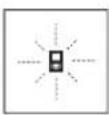
H3mepHTeBbHINHCTpyMeHTOTcHexKHaET npaBHbHOCTb pa6Otbln KaJOM H3mepeHH. PnO6hApUkeHHI DeEkeKaTHa IINCIIee OTo6pKaHaETCnTOBko CMBOL, NOKa3AHbH pAOM.B TAKOM cnyae Hnn ecN Bam He yda
ETCAYCTPAHHTHeNoJaKByBbIeHa3BaHHbIMMepAMN,OTnPaBBTe CBOH N3MePHTeBbHbINHCTpyMeHTYepe3MaRa3NH BCEPBCHyIO MaTepckyo Bosch.
TexobnyKbHaHne cepBnC
Texo6cnyxHBaHne n ouhctka
XpaHHTe HnepeHOCITE H3MepeHTeBHyI HNCTpyMeHTToBko B pnpnaIaraoUeMcR 3aunTHOM qexNe.
CoepKeHnTe H3MePHTeBbHbI HnCTpyMeHrNocToHHo B uH-CTOTE.
HnKOrJa He NoIpykaTe H3MePHTeBHyINHCTpyMeHT B BOyHnDpyrHe XIKKOCTN.
BbItnpaTe 3aRpa3HeHn CyXo H MArKO TpAknKo. He nCnonb3yTe KaKe-Im6 OuNCTaUe CpeDCTBa HnN pAcTBOpHTeH.
Oc6eHHO octopoxH O yxaKbAte 3a npHeMHO IINH30I (17), CIOBHO 3a OHKAMN HIN INH30I FOToannapaTa.
Ha pemOH TOpPabIe I3MepHTbHbI HHTpyMeHT B 3a- uTHOM YExNe (24).
CepBnKoHcyNbTHpOBAHHe NO BOpocam npmehenna
CepBnchbOtDenOTBeHTHaBceBaunBonpocbIpopeMOHTyOBcnyKbBaHIO BaWero npOdykta,aTakKeNo3an-actrM.N3o6paXeHHcnpctpaHCTBeHHbIMpa3deneHHemDeNaTeHnHΦopMauHIO No 3aNuaCTM MoKHO NOCMTpeTb TAKKe no aDpcy:www.bosch-pt.com
Konkehtb ctpyndnKOB Bosch, npedocabnHIOuN KOHCyIbTaunHa npdMet HcnoIb3OBAHN npodykUn, C yDobOBCTBHeM OTBeHT Ha BCE BaUN BONpOcbl OTHOCHTeB-HORo HAwei npdyckun H ee npHHaNekHoCTe.
IpoKanyuCTa, BO Bcex 3anpocax n 3aka3ax 3anacte o6ra3aTeIbHO yKa3bBaIte 10-3HaChbI TOBapHbI HOpE p 3aBODcKO TaBnUKe H3dEJI.
ДяpernoHa:PocChy,Benapycb,Ka3axCTan,YkpanHa
FapahTnHoe 06cnyKbAHne n peMOHT 3neKTponHCTpyMeH Ta, c 6oBIOeHNem Tpe6oBaHN HOpM 3rTOBNTenI npOuH3BOATCnHa TePPHTOPHN BCex CTpaH ToJIbKO BΦHPMeHHbIX nIN ABTOPH3OBaHHbIX cepBNCbHX ueHTpax «PObepT BoU”. IPEyIPEXKDEHNE! McOnIb3OBaHNe KOHTpaKaTHOH npOdyKUn OnACHO B 3KcNlyatauHN, MoKe TnpNBecn K yuepe6y dIra BaWero 3dopOBBy. N3rTOBNeHne n pacnpocTaHeHne KOHTpaKaTHOH npOdyKUn ppeCneJeYETcNo 3aKOHy B aMNHnCTpaTHBOM n YrOBoBHOM nopAKe.
Pocchm
YIOnHOMOeHHa HrTOBHTeNEM OprAH3aUH: 000《Po6epToBou》BaWyTHnKcE WoCCe,Bl.24 141400,r.XmKn,MockOBckAo6n.
Ten.: +78001008007
E-Mail: info.powertools@ru.bosch.com www.bosch-pt.ru
Bénapycb
HIN《Po6epT BoW》000
CepBnChbI ueHrpo 06cnyKbAHIO 3neKtpOnHCTpyMeHa yI. Tmnpa3eBa, 65A-020
220035, r. MHHCK
Ten.: +375 (17) 254 78 71
Ten.: +375 (17) 254 79 16
ΦaKc: +375 (17) 2547875
E-Mail: pt-service.by@bosch.com
Ofpuanbny caT: www.bosch-pt.by
Ka3axctan
LcHtp KOHCyIbTnpoBaHaHn npneMa npeTeH3n
TOO «PobepT Bω» (Robert Bosch)
I.AmMaTbI,
Pecny6nka Ka3axCTan
050012
yn.Mypat6aeba,180
BLC «Fepmec》,73tax
Ten.: +7 (727) 331 3100
c: + 7 (727) 2330787
E-Mail: ptka@bosch.com
POnHyIO nAkyaIbHyIO INHΦopMauio O paCnIoNoKeHHN cepBNCbIX cHTPOB N pRnEMhblx IyHKTOB Bbl MOxTe NOlyuHTb Ha OΦnuaHbHom CaIte:
www.bosch-professional.kz
Mondoba
RIALTO-STUDIO S.R.L.
П. KaHTeMnpa 1,этж 3,ToproBbI ζeHrT TOIIA3
2069KnHnHeB
Ten.: +373 22 840050/840054
a c : + 37322840049
Email: info@rialto.md
Knpn3ctah, MoHronna, TaXnKnCTaH, TypkMeHHCTaH, y36eknCTaH
TOO «Po6epr Bow» (Robert Bosch)
Power Tools noclenpodaJHoe 6cbnyXHBaHne
yn. Mypa76aeba, d. 180
050012 AImaTbI, Ka3axCTaH
Cnyke6haa n. nouta: service.pt.ka@bosch.com
OfuaHbHbN Be6-caHT: www.bosch.com,
www.bosch-pt.com
TpaHcnpTnpOBka
HaBIOXeHHbIe NITHeBO-HoHHbIe AKKMyIaTOPHbIe 6batape pacnpcOtpaHJIOcT Tpe60BaHIN B OTHoWeHN TpaHCnOpTNPOBKN OnaChbIX rpy3OB. AKKMyIaTOPHbIe 6batape MOryT nepeBO3NtCBcramm IOnb3OBaTelem ABTOMO6nJIbHbIM TpaHCnOpTOM 6e3 Heo6xOuMoCTn Co6JIouDEHn DOONHHTeJIbHbIX HOPM.
PnIpeBoaKe C npNBueHem TpeBnx NUI (HaNP.: camo-letom nIITpAHCNOpTHbIM 3KcneDHTOPOM) Heo6xOJIMO co6JIOaTb Oc6bIe Tpe6oBaHn K ynaKOBKe m MapKnPOBke.
B3OMcnyae npn noJroTOBKe rpy3a K OTpaBKe Heo6xOmo yuaCTne 3KcnpeTn OOnaChbIM rpy3am.
Ytnn3aun

H3MePHTeBHe HNCTpyMeHtbl,3apnHbIy cTPOcTBa,AKKMyNAToPbHbIE 6aTapeH, npHaJnHexHOCTn yNaKOBky CneJeYeTynH3npoBaT 6e3ONaChbIMdNOKpyKaIOSeCpebl6pa3OM.

YTHIN3Hpyte H3MePHTeBHe IHCTpymeHTbI, 3apAHBle yCtpoCTBa n AKKyMnTOpHBe 6atapeoTdeBHOOTbTOBOrO Mycopa!
TolbkoДгЯстан-ЧilehoB EC:
BcootBeCTBnC eBponeckOДnpeKTHBOB 2012/19/EC OTCnyKBWNE CBOI cPOK N3MePHTeMbIe Inp6Opbl N B coOTBeTCTBnC eBponeckOДnpeKTHBOB 2006/66/EC DeΦeKTHbIe HN OTCnyKBWNE CBOI cPOK aKKyMylTopHbIe 6a-tapeH/baapeKN dONXHbI coBupatbca pa3dEnbHO n CdaBaTbCn Ha 3kONoRnueckn UChTyO peKynepauuio.
AkkymyIaTopHbIe 6aTapeH/6aTapeKn:
JIITM-HOHOBbie:
IpoKaIyIcTa, yuHTbIaBte yka3aHnBa P a3dJeIe "TpaHcnOpTInpOBAk" (cm. ,TpaHCnpTInpOBAk", CtpaHnca 193).
HnterhpnoBaHHbe akkymnyTophble 6atapen pa3peWaaetc H3BNeKaTb cneuaHCTam n TOnbKO dnyTHn3aunn. BckpbTne Kopnyca upeBaTO pa3pyeHem n3-MepHTenbHO rHCTpymEHa.
UTo6bI 3Bnueb AkymyIaTOpHyO 6aTapeIO 3eKTPoHCTPymEHTA, nCNoB3yIte 3NeKTPoHCTPymEHTo TEXnop, noka AkymyIaTOpHaa 6aTapeI nonHOCTbIO He pa3pI-DITcB. BkpyTHe BNtBI Ha KOpNcE HCHMITE oBWHBYKOpnyCa, UTo6bI 3Bnueb AkymyIaTOpHyO 6aTapeIO.Bo I3-6bexaHHe KOPOTKO 3aMbKaHIn OTOeDHNHe NO OpeEIN BCE KOHTAKTBHa AkymyIaTOpe I N30nPyTe NOIocA.DaKe NoCne NoHOn Pa3pIKn AkymyIaTOpHaa 6aTapeE EHEMeET OCTaTOHyEO EMKOCb, KOTopaM MoKET BBICBOODITCB PnIKoPOTKOM 3aMbKaHIn.
yKpaIHcbka
Bka3iBkn 3 texhikn 6e3nekn


IpoHTaTe BcI BKa3iBKn i
IDOTPMMyTEcX,IO6
npaIOBAtn 3
BmIPoBaIbHM
InCTpyMeNTOM 6e3neHNO Ta
HadiiHo. BnKOpNCTaHHB BmIPIOBaNbHOrO IHcTpyMeHTa 6e3 DoTPMaHH cHx IHcTpKcui MoKe npu3BecTH Do noWkoJXeHH HTERPOBaHN 3axHCNH MEXaHI3MIB. HikoH He DOBoIbTe NopeDxyBaHbHi Ta6NIuKN Ha BmIPIOBaNbHOMy IHcTpyMeHTI Do HeBni3HaHHoCTI. IO6PE 36EPIAITE Ll IHCTPyKUII IIEPEDABAHTE IX PA3OM 3 INPEDAUYEO BmIPIOBaNbHOTO IHCTPYMEHTA.
06epexho-BHKOPnctaHH3acobib6cnyrobyBaHH iHactpoOBAHH,IOBip3HHTbChBid3a3Haehnx B
iiinctpykui, a6o BNKOpNCTaHH Do3BoneHHX 3ac06iB y Heo3BoneHH Cnoci6, MoKe npH3BOdHTN do He6e3neuHOro BnHbBy BnnpomHOBaHHa.
BmipobanbHH IHcTpMeHnocTae3
nonepaKyBaHbHO TOabNmuKoO (Ha 306paXeHHI
BmipobanbHorIO HcTpMeHTa H cToPiu3 MAnIOHKOM
BOHa No3HaueHa HOMepom (20)).
IEC 60825-1:2014 <1 mW, 635 nm
Laser Radiation Do not stare into beam Class 2 laser product
AkytoeknonepdxyBaIbHO Ta5nHnHaHncaHH He MOBOO Baoi KpaHH,nepe nepuHM 3anyCKOM B EKcNpyatauio 3akNeTe II HkNeIKOHO HA MoBI Baoi KpaHH,IO BXoHTb y KOMNKeT NOCTaAHHH.

He HanpaBnIe Na3epHn IpomInb Ha IIOJe a6o TBapH, i cami He nHBtbcHa npamn a6o BiO6paxyBaHn Na3epHn npomInb. BIn MoKe 3acniNTHn IHnx IIOJe,
CnPnHHTN HeaacHi BnnaKn a6o NooKoDHTN Oui.
ypa3notpannaHnna3epHoro npomeHa BOKO, HABMnche 3anIOUIb oui i BiDpa3y BiBepHITbcBID npomeHa.
HiOro He mHnTe B naePhomy npncToi.
He BHKOPNCOTBye OKyIrpN Dn p6oTH 3 na3epom kaxnci OKyIrpN OkyIrpN Dn po60Tu 3 na3epom 3a6e3neuyIOb KpaIe po3ni3HaBaHHra Na3epHOro npOMeHIO, OndAKe He 3axuiaOb BiD Na3epHOro BInpOMIHOBAHHA.
He BHKOPNCOTBye OKyIrpN Dnpo6Otn 3 Na3epom Ra coHue3axnChi OKyIrpN Ta He BnraTe ix, KOnn Bu 3hAxoHntec3a KePMOM. OkynpDnpo6Otn 3 Na3epom He 3a6e3neuYbT NobHn 3axnCT BiYΦ npOMEHB Ta NoripWHyb po3ni3HaBaHHK OkbopIB.
BidabaiTe BmipIOBaIbHn IHcTpymENT Ha peMOHT NHe KBAiDfIKOBAHM faxIBaUM Ta NHe 3 BHKOpHCTAHNM OpriHaNbHnx 3aNactNH. TlBKn 3a TaKHX yMoB BaW BmIPIOBaIbHn npIaI i HaNani 6yde 3aHHaTNC 6e3neuHM.
HeO3BOJRATe DIYAM BHKOPHCOTByBaTH na3epHn BHmipOBaBbHn IHCTpyMeHT 6eHaHny. DITMOxTyb HeHaBMNCHE 3acNIHTn IHxN IIOJe.
He npaioite 3 BnMipobalbHm iNCTpyMeHToM y cepeoBnu, de icHyc He6e3neKa B6yxy BhaCniok npcyTHOCTI rOIOHN pINH, ra3IB aBO nNNy. Y BnMipOBaHOMy npnaDi MOKyb yTBOPOBaTHCA ICKPN, BiJAKX MoKe 3aIMaTHCA NnA bAO napi.

3axhaTe BmipobbHn IHcTpMeHTBd HarpibaHn, 30KpMa, Hanp., Ha coHui, a TAKOX BiD BorHIO, BOH Ta BONrH. IChye
He6e3neKa Bn6bxy.
He BHKOPNCOTByTe BHMIPIOBANbHN iHCTpyMeHT 3i BCTpOMJIeHM Ka6eJem Micro USB.
Bka3iBkn 3 Texhikn 6e3neKn dIa 3apAHHN npHcTpoIB
3apnHn npncptiH nepe6aueHH nBVKOpntAHn dItbMn i oc6amn 3 06mexHmN 3uHMM, cHcOpHMM Ta pO3yMOBmm 3di6HOCTAMn, a6o HeocTaTHIM DOCBIDOM Ta 3HaHHMa. DiTAM BIKOM Bi8 pOKIB Ta oc6am 3 06mexHMM 3uHMM, cHcOpHMM Ta pO3yMOBmm MOXJIHBOCTAMn a6o HeocTaTHIM DOCBIDOM Ta 3HaHHMa. D03BOJAEtbcra KOpNCTyBaTHCn zHM 3apAHHM npncTrooeem IInwe nId Hargldom a6o Jkso BOHN OTPMaII N BiINOBIHI Bka3IBKn 0do 6e3neUHO BVKOpHCTAHn CuBOr O 3apAHO rnpctpoio I po3ymIOTB, kY He6e3neKy BIn Hece. IHaKSe MoKJIVe
HnpaBnIbHe BnKOpNCTaHH Ta He6e3neKa OepJkaHH TpaBM.
DornaTe 3a itbMn iad yac KopnctyBaHH, ouuueHH I texHicHoro o6cnyroByaHH. Pn uby ckiKyte 3a Tm, o6 dITn He rpanca i3 aapdHM pncTroem.

3axuainTe 3apnnpctpiB iD ouyi BONrH.
PonadaHn BOnnB eEnkTponpna36inbWyec pnsK npaxeHH enEeKTPnHm CTpyMOM.
3apJxKaTe BmipObaIbHn IHCTpyMeHT nIe 3a DOnOMOrIO DoaHOr 3apJHOrO npCTpoIO.
TpmaTe 3apHn npctpi B uCTOTi. Pn 3a6pydHeHHx icHy eHe6e3neKa ypaKeHH enektpuHm CTpyMOM.
KoJHOrO pa3y nepeBnKOpNCTAHm nepeBipraTe 3apAHH npncpti, uHyp ta wTenceNB. He BnKOpNCTOBYte 3apAHH npctpi, kUc06yHn BnABHeI nowKOxEHn. He po3kPbAte 3apAHH npctpi camocTlHo, IX pEmOH d03BOHReTbCBy BHKoHyBaTH NHwe KBaIIΦIKOBaHOMy nepcohany i NHwe 3 BnKOpNCTAHm opHrHaHbHNX 3aNactNH. POnkOxKeHi 3apAHH npctpoi, uHyp afo wTenceNB 36InbUye He6e3neky ypaJaeHH eEeKtpuHm cTpymom.
He BnKOpNCbOyTe 3apHnH npNcTpi Ha nERko3aMmCTiIO nobExnI (Hanp.,Ha nanePi,TKaHHn Too) a60B NoXkapone6e3neuHomy cepeobnui. Upe3 HarpBaHn3 3apJHoro npncTpoIO niac 3apJkaHnBnHKAc He6e3NeKa 3aMaHnH.
Pn nookxheni 60 he npabnbniE ekcnnyataaikymytohpoi6ataei moke bHXoHTn nap.BnycttbCbKe NOBtpr-i-y pasi ckapr-3BepHitbcn do nikapra. Nap moke noDpa3HObatn dXxaJIbHI WJAXN.
BIMMIPIOBAHHIOBXHH
BmipioBaHHnnoi
BnMIpHOBaHHo6'Emy
TpBane BmipHOBaHHA
Henpme BmipioBAHHBVCOTn
IIOBIIHe HnPme BmIPHOBAHH BnCOTH
HenpameBmipIOBaHHIOBXHH
yHKui TaHMepa
BmMipHOBaHHnNooJI cTIH
BnMipioBaHHa KyTb HaxHny
(g) INIINaTOP 3apJxHeOCTi akymyTnTopHObTaapei
(h) Ia3ep yBIMKHyTNI
(i) Ba3OBA nIooHnA npn BmIpIOBaHHi
(j) IHHaTOp BHXOy 3a MEXi TemepaTyphoro diana3oHy
TexhiuHa
UcfoBovn naeepn nnalekomip GLM 80 GLM 80+R 60
Bka3iBaK: AkymyIaTOpHa 6aTapeN noCTaaytbcyaCTKOBO 3apJxKeHO. Ioo6 akymyIaTOpHa 6aTapeMOrna peani3yBaTH CBOH NOBHy cMHICTb, nepeT TM, Ra nepuH pa3 npauoBaTH 3 IHCTpyMeHTOM, akymyIaTOp Tpe6a IOBHCTIO 3apJNTn.
IitieBO-iOHHHaKMyJrTOPOMOHs3apAkaTH KOJIH 3aBROHO,ue He cKOpOyE Horo EKCnnyatauiHHnepcypc. IpeepBaHH npocecy 3apAkaHH He noikokjye akyMjTOp.
Akuo nouHaC 6nMaTH HnKHi ceMHT IHnKaTopa 3apJKeHoCTakyMylTopHObatapeI (g),MOxHa BnKoHaTI iue nHe DeKInbKa BmIpObaHb.3apAdt b akyMylTopHy 6batapeIO.
Akyo Mnae paMa KaHaBkoNc cerMeHTiB IHnKaTopa 3apJxHoeCTi AkymyIaTOpHOI batapei (g), noaJIbwi BmipOBAHH HeMOxKInBi. KopnCTyBaTHCra BmipOBAhHM IHCTpyMeHTOM MoXHa ue Nlwe KopoTKn Yac (Hanp.,dna nepeBipKn 3anCIB y nepeniky BmipRnHex 3haeHb). 3apJntb akymyIaTOpHy batapeio.
Iiuc3apdKaHn npaObaTH 3 BmipOBaBHM IHCTpyMeHTOM He MoXHa.
Bepexitb3apdnn npncptpi BID Bonorn!
Bka3iBKN 3 ONTNMAnbHoro NOBODKeHH 3 akymyIaTOPOHO 6aTaapeCIO y BmipHOaNbHOMy IHCTpyMeHTI
36epiraTe BmipobanbHn IHCTpymeT Nwye 103B0JeHOMy TempeatypHom y iana3oHi, (DnB.,"TexhiHi daH",CtoPiHa 196).He 3aHnwaTe BmipobanbHn IHCTpymeHT,Hap.,BnITky,BABtOMo6ini.
3aHaoKoPOTKa TpBnBnictbpo60tnnicna3apJxahnn CBiDHTb npTe, 10 akymyTOp Bvepnab ce6 i Horo
notpi6HOn NOMIHnY cepBicHi MaIcTePHi Bosch. 3BaKaJte Ha BkazIKuOIO BuJaIeHHa
P60ta
Noataokpo60tn
3axnauTe BHMIPIOBbHn npnaD BiD BOIOni COHnHNx npomeHIB.
HeOnyckaiTe BnNBy Ha BmipobanbHn IHcTpymEt ektpemalbHx TemnepaTpy a6o TemnepaTyPhNX nepenaiB. Hanpknad, He 3aIIwaIe Ioro HADOBRO BAETOMObiI. RaIO BmipobanbHn IHcTpymEt 3a3HBv BnNBy BeNKORo nepenady TemnepaTyP, nepu HIX BHKOPICTOBYBatn Ioro, daIte Ioro TemnpaTypi cta6ini3ybatnc. EktpemalbHi TemnepaTyPi Ta TemnpaTyPi nepenadi MoKyTB NoripuyBat ToHicThB BMIPOBaBHOro npnndy.
YHnKaIe CnIbHnx NOITOBXIB i naIHnB Hmipobalbohoro IHcTpymeHa. IicnIcNbHx30BHIIXxBnNBIB Ha BmipobalbHn IHCTpyMeHT nepeI npaIbwoIO po6OIO o6OB'a3KOBO 3aBXn pepeBiprTe ToHicTBpo6OTn BmipobalbHO IHCTpyMeHa (DNB."PepeBipka TOnHOCTI Ta Kani6pyBaHH nI BmipobAHnKyTa Haxnly (DNB.Man.H),CTopiHKa 203)i (DNB."PepeBipka ToHocTI BmipobAHN BiDCTaHI, CtopiHKa 203).
BMNKaHHBMMKahHH
He 3aHnwaTe yBIMkHyTn BmIPIOBaIbHH IHcTpMEn 6e3 DoIy, nCn 3aKInHHe pO60TH BmHKaTe BmIPIOBaIbHH IHcTpMEn. Iuoi oco6MoKyTB 6yTu 3acJinneHi naepHM npomehem.
Eekibka cnoocbiyBIMKHeHHBMMipObaHoro IHCTpyMeHTa:
-HaHCHtB Ha BmHKaU (8): BmMIPoBaIbHn IHCTpyMeHT BMKaTbCra 13HaxOJNbCB RpeKIMi BmMIPoBAHH DOBXHN. Na3ep He yBIMKHyTN.
-HaTNCHTb KONKy BmIPHOBaHHa (2):BmIPHOaJIbHn IHCTpyMeHT Ia3ep BMNKaIObCBA. BmIPHOaJIbHn IHCTpyMeHT nepe6yBaE B peXHMI BmIPHOBaHHa DOBXHN. Y BCTaHOBNEHOMy Ha BmIPHOaJIbHy peKy (25) BmIPHOaJIbHomy IHCTpyMeHTi aKTINBOHa hФyHKU BmIPHOaHHa KytIB HaxNny.
He cnpaMOByTe Na3epHn IpomInb Ha IIOpei TBapn i He DnBtbcy Na3epHn IpomInb, BKNIOUaOuN i 3 BeNHKOI BiDCTahi.
Lio6BMMKHyTH BMMIPHOBAHbHH IHCTpyMeHT,IOBHOHaTHCKaHTe HaBMHKaU (8).
KIO npOTaROM np6n.5XBN. He HATNCKaETbCJKOHa KHONKa HA BHMIPIOBaIbHOMy IHCTpMeHTi, BHMIPIOBaIbHN IHCTpMeHT aBTOMaTHNOBHMNKaETbCJ, 0o63aoaAnTH 6ataeii.
AkpB pexnmi po60tn BmipobHna Kytih Haxny 3haeHHa KyTa He 3MHOCTbCn PpOraTOM np6n.5XBn. BmipOBaHbHn IHcPymEt ABtOMaTHo BmNkaCTbCn, 3o6 3aoaadnt 6ataei.
PnabTOMaTHyOMBmKHeHHI Bci 3HaueHn,IO 3anHcHi B nam'rtb,36epiraOTbcra.
PpoeDypa BmipBoHHA
Iicra yBIMKHeHHHaTnCKyBaHHMa KHONky BmIPHOBAHna (2) BmIPoBAJIbHN iHCTpymEt, BCTaHOBJeHN Ha BmIPoBAJbHy peKy (25), 3aBXJn 3hAxOJNbCBa B pexmi BmIPoBAHHa DOBXNHa a6o KytB HaxNy. IuIpeXHMn BmIPoBAHHa MOxHa Bn6paTH, HATNCHYBn Ha BiDnOBiHy KONky pexnMy (INB. ,FyHKUII BmIPoBAHHa", CtopIHka 200).
BЯкстба3OBOППLOUHHNIIICNBAIMKAHHBCTAHOBHeHn 3aHн Крв BMIPIOBaIbHOrIO INCTpyMeHTA. HatNCKaHHM KONKN Bn6opy 6a3OBOППLOUHHN(10)6a3OBY PNOUHy MOxHa 3MinHTN(INB.Bn6ip 6a3OBIПLOUHHN(DINB. Man.A),CTopiHa 199).
Pnuctabe BmipioBaNbHn iNCTpymeHT Bn6paHO 6a3OBOI nIOuHHo DO 6baKaHO BNXIDHOI TOKN BmipioBaHH (HaNP.,do CTiH).
Uo6 yBIMKHyTN na3epHn npomihb, KOPOTKO HATNCHTb Ha KHONKY BmIPIOBAHHA (2).
He cnpaMOByTe na3epHn npOMiNb ha IIOJe i TBapHH I He nDIBiTbC y na3epHn npOMiNb, BKIOUaOuN i 3 BENKOI BiCTani.
Habeitb na3epnH npomHb Ha ciNboby noBepxHIO.106 3diHHTN BmIPHOBaHH, 3HOBy KOpOTKo HAtCHITb Ha KHONKY BmIPHOBaHH (2).
Pn yBIMKHYOMy NOCTHOMy Na3epHOMy npomeHi BmipOBaHHNouHaCTbCg Opa3y nicn nepwOro HaTNCaHHHa KhoNky BmipOBaHH (2).BpeKmi TpBaIoro BmipOBaHHBmipOBaHH po3noHacTBcB BiPa3y Nicy yBIMKHeHH peKmY.
Bmiphe 3aehnHa 3'ABTbCra, kI npabHIO, npotarom 0.5c, MaKcHymU yepe34c. TpBaNlrcb BmipHOBAHH 3aEnKtB BiD BiCTahi, ocBiTIeHH I Bi6NBHOI 3aTHOCTi ciJbOBoIO NOBepxHi. IpO 3akIHueHH BmipHOBAHH CBIDHT b3ykoBn CnHAn. NcIa 3akIHueHH BmipHOBAHH Na3epHNI pOMIHb ABTomATNu HO BMNKaETbCra.
Akpnoptarom np6bn.20cnicnaHabeenHa cnB BMIpOBAHH He 3iINCHIOCTcra,naepnnpOMIHbIa3oauadKeHHN AkyMnyATropHO bataei aBTOMaTHHO BmHKaETBCr.
Bh6ip 6a3oBOI nloounHH (nVB. Man. A)
PnBnBmipIOBaHHI Bn MoKTe Bn6paTH ONDy 3OHTnpbOx 6a3OBHX NIOUH:
-3aHnKpaBmipBoaHOroInCTpyMeHa a60 nepeHnKpa BIDKNHYTOHa 90°ynOpHoro WTHΦTa (9) (Hanp., npnnpctabnnHi Do 3OBHIwHix KyTb),
-kiHnK BiKNHyTOro Ha 180° ynOpHOro uTnΦTa (9) (HaNP.,ДЯ BIMiPObaHb 3 Kytib),
- nepeHnKpaB BmipOBAhBOHO INCTpyMeHTa (Hanp., DnB BMIPOBAHBaI KpaO CTOnA),
-cepeHnHaPi3b6oBOrOOTBOPY(19)(HnP.,nBIMipIOBaHb3iIHTABOM).
UoBbpaTH 6a3OBy nOuHHy, HATNcKaIte Ha KhoNky (10), NOKHa DNcPiTe He 3'ABNTbCra Heo6xIdHa 6a3Oba IIOUHa. KoxHH pa3 nicr BMnKaHH B JKOCTi 6a3OBoI IIOUHH BCTAHOBIOETbCra 3aHi Kpa BmIPoBaIbHorO IHCTpyMeHTA.
3MiHa 6a3oBoI IIOOHHnIyue 3diIcHEno BHMipOBaHH (Hanp. npi HnKaJIiB BMIpAHx 3HaueHb B CnCKy BmipAHx 3HaueHb) HEMOXINBa.
Meho《Ba30bi HanaTByaHHA
I06notpanHTBMeHIO《BaOBI HanaHTyBaHH》,ytmyTe KHNky 6aOBHX HanaHTyBaHb (4).
KopOTko HaTCHITb KHONky 6a3OBHX HanaTuBaHb (4), uo6 Bn6paTH OkpemI NyKTH MeHO.
HaHCHIb KHOJky(MInyc)(5)abO KHONKY(NIOc)(11), 06Bn6paTHaHaHTyBaHHBnyHKTxMeHIO.
UoB BnTn 3 MeHIO 《Ba3OBI HanaWryBaHHa》,HaNTCHITb Ha KHOJIky BmIPIOBAHHa (2).
Ba3oBi hanaHTyBaHHa
3BykoBi cHrHaHn YbIMK.

BMMK.
IipcbiyuBaHHnDinCnnerYBIMK

BMMK.

ABTomatnuey bIMKHeHHB MIKHeHH
LHΦpOBn BATEnpac YBIMK.

BMMK.
06eTpAnHHIINCnpeyBIMK.

BMMK.
IocHHnJa3epHn npOMInb

yBIMK.

BMMK.
OuHHnue BHMipIOBaHHB BiCTahi(B3aJIeXHOCTiBiD KpaIHn)
M, ft, inj,...
OHHHnBmipOBaHHKytIB (B3aneXHOCTi BkPaiHN)
% ,MM / M,in / ft
Okpim HanaaTyBaHHA «NocTihn Na3epHn npomIHb», Bci 6a3oBi HanaaTyBaHHa 36epiraObCnIcnaBmKHeHH.
TocHnHa3epn npomih
He cnpaMoByte na3epHn npomihb Ha IIOpei TBapHH i He nBIBtbcy na3epHn npomihb, BKNIOuOCH i 3 BENIKOI BiCTahi.
PnUcbomyHanauTyBaHHIa3epHnnnpomih3aHmaaetbCByBIMKHTM TAKOX MIX BHMIPBOAHHMR;IO6po3noatBNMIPBOAHH,DOCTaTHbO OHNpa3HaTCHHTHa KHONKYBMIPBOAHH (2).
Функць Вииміровань.
PpOCTeBmipOBaHHIIOBXHHI
IINBHMIPIOBAHHIOBxHHHaTNCaTe DeKInbKa pa3iB KHONKY (12), NOKN Ha DCnPeI He BiO6pa3ntbCra IHINKAtOp BHMIPIOBAHHIOBxHHI
Uo6 yBIMKHyTn na3ep i 3diHCHTN BmipIOBaHH, KOPOTKO HATnCKaIte KHONKY BmipIOBaHH (2).
BnMipraHe 3HaueHH BIO6paKaεTbcy y pAnky (c).
Akyu Bu 3iHcHoeTe KeinbKa nocIIOBHNX BmIPBOHaH bO8KHHN,TOpe3yNbTaTnOCTAHHX BmIPBOHaH 3'ABJIOTbcR B pKaX BmIPaHx 3HaueHb (a).
Bmipobanha npo
ДлвИВИМЮВАнHA ПLOОПΙΝΥОВЖУТЕ HATNCKYBAITH KHOKNY(12),NOKHaДИСПЛЕI He 3'RBNbCЯHINKHATOP BIMIPIOBAHHI PLOOJI□
Picra zbo ro no cep3i BmipnTe u npHny i doxHny, k npBmipoBaHHIOBxHH. B nepepbi mix o6omaBmipoBaHHaMn Iaepn npomHb 3aIIuaeTbcyBIMKHyTM.
Ito3aBepuHHi npyroro BmipHOBaHHnnoa aBTOMATNUHO BnpaXOBYeTbCn i BiO6paKaTeCBnPnky BmIPrHnx 3HaueHb (c).Okpei3HaueHHN BkazaiHy pAnkx BmipRHN 3HaueHb (a).
BmipioBaHHa 06'EMy
HaTnCKaIte KhONky nepemKaNHHpeXmIB (4), nOKn Ha DCnJIe I He BiO6pa3Ntbcr IHnKaTOp HENPROMO BMIPIOBaHH DOBXHNN
CnIkyTe 3a THM, uOb BmIPIOBaHbHIn hCTpyMeHT 3hAXoINBcRa Ha ODiH i Tiin Cami BnCOTi, uO i ToKa BmIPIOBaHHra, kY Bn Bn3HaacAte. NotIM haxNilTb BmIPIOBaHbHIn hCTpyMeHT n BiDHOweHHIO do 6a3OBoi IIOounHn i BmIPraTe BiDpI3OK «1», kE pe oobntbcr y pa3i BmIPIOBaHHra DOBXHNH.
Piicra3aBepweHHN ocTaHbOro BmipobHnpe3ynbTAT nIyKaHOrO BiDpi3ka XBiDoppaKaetcbrpyRky pe3ynbTatIB (c).Bmiparhi 3naueHHn DnBip3ka 1 Ta kyTaA BiDoppaKaIObCB RpKaX BmipraHX
3HaueHb (a).
BmipioBaHHnnoi CTIN (MnB.MnF)
BmipoubaHHnIooi CTIN Do3BOJRE Bn3HaHTN 3araIbHy nIOOy DeKInbKOx OKpeMnx DInrHOK, IIO MaIOTb OHaKOBBy BNCOTy.
Y HABeHOMy pIKNaI HeO6xIHo OTPMaTH 3aRaIbHy IIOUy KeINbKOx CTiH 3 OJHaKOBIO BHCOTIO KIMHATn A,ane pi3HO IOBKMHOIO B.
BnMIPIOBAHHIIOOi CTIN HAITNCKaHTe HA KHOKNy nepemikahnpeKIMIB4)10KNHaDNCJIeHe3'ABNTbcra IHNKATOP BnMIPOBAHHIIOOciTIN
Pmiprte BnCOTy KIMHaTHA, kIe peo6ntbcy y pasi BmipIOBaHHIOBxHH. BmipHe 3HaueHHe (cst) 3'BAHTbCy y BEPxHbOMy PAnky BmipAHx 3HaueHb (a). Pa3ep 3aNNaetcby yBIMKHyTM.
Tenep nomipraTe doBxHnBu nepwoi cTHn. IIOOa nIpaXOByETbCABTOMaTHUHO i BkaycBcA y pRky pe3ynbTaTy (c).OctaHHe 3HaueHHB BMIPHOIOBxHHN BkayetbCAY cepeHbomy prky BMIPAHx 3HaueHb (a).
Ja3ep 3aIIHuaeTbCyaYBIMKHeHIM.
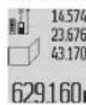
Tenep nomiprte DOBXHHy B2 dpyroCTIHn.
Bka3aHe y cepenHbOMy pKy BmIPraHX
3HaueHb (a) OKpeMe BmIPraHe 3HaueHH
D0daETcbNo DOBxHN H B1.Cyma 060 x DOx BHN
( 空 sum), BiO6paKaεTbCry y HNKnbOMy prkky
BIMipraHHx3HaueHb(a) NOMHOxytbc8nHa 36pepeKeHy B namTBIncOTyA.3HaueHn3aRaJIbHoI pIoI BiIO6paKaetbc8 npKpype3yNbTaTy (c).
MoXHa NOMiPrtn 6yDb-Aky KInBkictb DOBXHH B, Aki ABTomATNUHO DOnaIbCn I NOMHOXYIOBcHn HBCOTyA.
InpabnboHO BVmipOBaHHnlooi Heo6xidHO,io6 BmipHa nepsha DOBxHna (y npKnadi - BnCota KIMHaTn A) 6ya iJeHTNuOIO nn yicx Okpmnx nIoU.
BmipioBaHHkyTIB Haxnny (DHB.MaI.G)
Ypa3iHaTnCKaHHK HONKNBMMIPoBAHH KytTB HaxNy (3) Ha
HcNnei 3'ABNLCTBCA INHkATOP BMMIPoBAHH KytTB HaxNy
. Ba3OBOIO NIOUHO E 3aHIN KpaB MMIPoBAIbHORO
IHCTpyMeHTa.Y pa3i NOBTOPO HO HA TnCKAHHA KhoNky
BMIPoBAHH KytIB HAXNy (3) 6a3OBA NIOUHa
NEpEXOHTb Ha 60KOBI NOBExHI BMMIPoBAIbHORO
IHCTpyMeHTa I 3OBpaXeHH HA DnCnEIOBepTaEcBa H90°
HaTNCHTb KONKY BMIPoBAHH (2),IO6 3aPikCyBaTH
BMIPrHe 3HaueHH Ta 36ePeITH NorO B NaM'Ati BMIPrHHX
3HaueHb. PnH NOBTOPHMy HA TnCKAHHi HA KHOKNY
BMIPoBAHH (2) BMMIPoBAHH NPOOBxKyETbcR.
KuioB npoucici BmipobAHn6bnmae iHnkaTOp,TOce O3Haue,IO BmipOBaIbHN IHCTpyMeHT 3aHaTTo CnIbHO HaxInenHH B6iK.
RkUo Bn yBIMKHyN B OCHOBHX HAcTPOJkax FyHKqio UInpOBN BaTePnac,3HaueHn KyaTa HaxNy BiO6paKaTbCn TaKox IBiHux FyHKuiX BmIpOBAHH B pAnky (d)DnCnpe1.
Функий Таймера
Функштамерадомаэ,нанр.,якшоnotpiбн
Злобгп pyхаHHBOBIMIPOBaHORO iHCTpyMeHTaПДчac
ВIMIPOBaHH.
UoB yBIMKHyTn cyHKuTo TaMepa, yTPMMyTe KONky (6) HATNCHyTOH, NOKn Ha DCNPeI He 3'ABNTbCnIHNKaTOP Y PAnky BmIPARHH 3HaueHb (a) BiIO6paXaEbCnPOMIXK O acy BID NcKy DO BmIPIOBAHH. HATNCKAHOH HA KHONky (11) a60 KONky (MInyc) (5) HAcTPOITN POMIXK O acy B dianazOHi Bid 1 cdo 60 c.
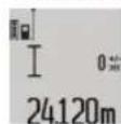
BmipobhaH3iINCHOETcABATOMaTHHO nic3akHueHHyCTaHOBHeHOIpOMIKky acy.
ФункшюТаиметаТAKOKMOЖHA3aCTOCOBYВATNпр
ВИМIPIOBAHHI BIDCTAHeB IINHIXpeKIMAX BIMIPIOBAHH
(Hanp.,прВИМIPIOBAHHI ПLOU).ДODaВATn Ta BiHIMaTH
pe3yIbTaN BIMIPIOBAHHA HEMOXJIIBO,po6ToB TpNBAlOMY
peKIMI TAKOK HEMOXJIIBA.
CnHcOK octAHIX BmIPaHHx 3HaueHb
BmipobanbHH iHctpyment 36epirae B nam'rti octahhi 20
BmipraHx 3aueHb ta ix po3paxyHKn i noka3ye ix y
3BOPoTHI NOCIIOBOHOCTI (ocTaHHe Bmiphe 3aueHH
CNoaTky).
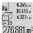
UoB BnKnKaTH 36peXeHbBmipnHaueHHHaNTCHITb KHONy(7).HaDcNnei3'ABnEhCBpe3yNbTatOCTaHHbOrB BMIPOBAHPa3OM i INkATOpom cnckyBMIPAHx 3HaueHb(e), a TAKOK KOMipka
nam'nti DnHymepaui BnMipIOBaHb, 0o 3'raBnIOTbcHa nCnnie.
KIO npn NOBTOPHOMy HATNCHEHHHa KHONKY (7) BmipobAHH6IbIe He 36epiraTbcR, BmipOBaHnIHCTpyMeHT NOBepTaETcB OCTaHH peKM BmipOBaHH. I06 cncOK BmipraHH 3aueHb 3HK i3dncneIO, HAChCHtB Ody i3 KHOONK peKMIB BMIPoBAHH.
Ioo636epeTn B KOCTIO KOCTAHTn AKTAYaJIbHe BMIMIpeH 3HaueHHN DOBKNH, IIO BIDo6paXaEc7cRa H DaNCPIE, TPImaTe KONKy CnCKY BMIPAHX 3HaueHb (7) HATNCHYTOO, NOKn Ha DNCLNEi HE 3'ABNTBCr «CST». 3aINc y CnCKy BMIPAHX 3HaueHb He MOxHa Ni3Hiwe 36epeTn B KOCTI KOCTAHTH.
UoB BnKOpNCTaTH BnMipAHe 3HaueHHIOBxHnB OOnHOMy 3 peXnMIB BnMipOBAHH (Hanp., BnMipOBAHH NIOuHN), HATNCHTb KHOKNy CnCKy BmIPARHX 3HaueHb (7), BN6epiTB Heo6XiHn 3AnC Ta NiTBePdTe, HATNCHyBn Ha KHOKNy pe3yNbTaty (6).
CtnpaHHBbMIPaHHX3HaueHb
KopoTKM HaTnCKaHHM Ha KHOKNy (8) MoXHa BuaJIaHTN B ycix pexHMax BmIPIOBAHHOCTaHHc BmIPIe 3HaueHH. KInbkapa3OBIM KOpOTKM HaTnCKaHHM Ha KHOKNy OKpeMI BmIPRIi 3HaueHHBuaJIaIOTbc y 3BOPoTHI nocliobHOCTI.
Lio6 cteptn 3annc y ctncky BmipraHnx 3haueh, 10c came Bncbiyebcna Hcnnei, KOPOTKO HATNCHTb KHONKY (8). Lio6 cteptn BeCb cncOK BmipraHnx 3haueh Ta KOHCTaHTy CST), ytpmyTe KNOKy cncCKy BmipraHnx 3haueh (7) HaTCHyTOO, OndouacHO KOpOTKO HATNCKAIOH KNOKY (8). B pexkmi BmipobAHn PNOU CTINn npn nepwOMy KOpOTKOMy HATNCKAHHI HA KHONKY (8) BNDJIeTcBc OCTaHHe BmipraHe 3haueHH, nPH dpyROMy HATNCKAHHI BNDJIaIObTCy iD0BXHHn B, nPH TpebOMy - BNCOTA pnpMIuEHHA.
DdaBHHBmipAHnx3haYeHb
Ioo doaTaBmipriH3HaueHH, BnKoHaTe cNoatky 6yDb- kY onepaio BmipIOBaHH a60 BNbepi8 3aNc i3 cNcKy BmIPAHX 3HaueHb. Notim HaTNCi8 KHOKNy (11). IJrPiTBepIXeHH HaDCnPei 3'ABnEhCBs, ^ .Notim BnKoHaTe dpyry Opeaio BmIPIOBaHH a60 BNbepi8 IHsH 3aNc i3 cNcCKy BmipAHH 3HaueHb.
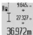
Дя onHTyBaHHc yM O6O xonepauiB BMIPoBAHH HaTCHiTB KONKpy pe3ynbTaTy (6).P03paxyHOK 3'ABnEtcB R pRkyBMIPaHHx 3HaueHb (a), a cyMa - B prKype3ynbTaTy (c).
Pn iipaxnyky cymno do zb0rpe3yntaty moxHa
doabatni Hsi Bmipri 3haeHHA a6o 3aueHH 3i CNCKY
BmipraHx 3aueHb, n4y oTOpi6HO nepeI noaTkom
BmipobHH KOKHOrO pa3y HaTHCKyBaTH KNKk PIIOC
(11).U6 3akInHTn DoaBAHH, HaTCHITb Ha KNKpy
pe3ynbTaty (6).
Bka3iBKN ⅢOIO IOdAbHnA:
-3NaueHnIOBxHH, nOuTi Ta o6'Emy He MoXHa 3MiUyBaTH npD OdaBaHH. HanpKnaI, y pa3i cnpo6n DoaTN 3NaueHH DOBxHH Ta nOuI, npN HATNCHeHH KONKN pe3yNbTaTy (6) HaDCNIeI KOPOKo 3'ABNAETbCRA «ERROR」. PicJIzOBO BmIPIOBaHbHIn IHCTpyMeHT NOBepTaTcB B NOpEpdHII peKHM BmIPIOBaHHA.
-ⅡOaεbca 3aBxJn 3aueHHe OJHO BmipHOBaHH (HaNP.3aueHHo6'my), a npn TpNBaIOMy BmipBOaHHi BmipHe 3aueHH, 10 BoIObpaKaεbca Ha DCNJIeB PAnky pe3yNbTaTy (c). IOnaBaHHo OKpeMnx BmipAHX 3aueHb i3 PAnKIB BmipAHX 3aueHb (a) HEMOXINBE.
BIDHimaHHB HmipHHX 3HaueHb
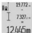
Дя BiHimAHHH BIMipHnX 3HaueHb HATNCHITb KONKу «Minyc» (5),ДЯ NiTBePdKeHH Ha DCNpei 3'ABnEeTcra «-».ПоанБш iIi anAoIurHi po3DIny «OdaBaHH BIMipHnX 3HaueHb>.
Bka3iBKn 0oO p6oTn
3araJIbHI BKA3IBKN
PnHOMHa nH3a (17)iMICue BNXOy naePHoro npomeHa (16) niJ cac BmipHOBaHH NOBHHI 6Ty BIDKPHTi.
Iiuc BmipobAHHe MeKHa nepecyBaTH BmipOBaBHH iHCTpyMeT (BnHTOK: yHKii TpHbAoro BmipOBaHH Ta BmipOBaHH KytIB HaxNy). Tomy 3a MOxNtIO NOKlaITb BmipOBaBHH iHCTpyMeH Ha MiCuHy ONOpHy NOBepxHO.
ΦaKToPH BnHbY Ha dIana3OH BmIpOBAHH
PaIyc BmIPHOBaHH 3aIeKHTb BiD ocBITneHn H I BiIDNBHOI 3aTHOCTi iINbOBOI NOBepxHI. LIO6 npn pO60rax HaDBopi a6o npn CInbHOMy COHcI KpaIe 6yNo BnHO Na3epHn npomHb, KopncTyTeca OKyIpaMn Dnpo60Tu 3Na3epom (28) (npnaJ) i B3nPnHm UHTOM (29) (npnaJ) a6o 3aTihb cINbOBy NOBepxHIO.
ФaktopиВПИБУнуHa pe3yIbTaT BmIpOBoHn
3BaKaIOH H a fiI3NHi efeKTH, He MOXHa BnKlOHTN NOMIKBpe3yNbTaTAX BmIPHOBAHH npn BmIPHOBAHHx Ha pi3HNX NOBepHXJ. COni BiHOcRtBCa:
- npo3opi noBepxHi (Hanp., cknlo, Boga),
- noBepxhi, 0o BiD3epKaIIOJb (Hanp., nonipobAHm MeTaN,CKNo),
-nopnci noBepxhi (Hanp. iOJnjiH mATEpiann)
-CTpyKTypoBaHI NOBepxHI (HAnp., CTpyKTypoBaHa 17ykaTpyka, npnpodnhi 6ydiBebnki KaIMh).
3a Notpe6n BHKOPNCTOByTe Ha TaKHX NOBepxHx B3HpHy Mapky (29) (npnaand).
PnKOCOMHaBeeHHi HaIb MOKnBi NOMNk. Kpim TOrO,Ha pe3yNbTaB BMIpIOBaHHa MOxTy BnINBaTH Wapn NobITpr 3 pi3HO TempepaTPO a6o Henpme BiD3epKaIIOBaHH.
Ipebeipka Touhocti Ta Kani6pyBaHHaBn BmipobHn Kyta Haxiny (DMB. Man. H)
Perynphno nepebipitte ToHictb Bmipobha Hkyta haxny. Lc 3iinCHIOETBCIOWXOM BmipobhaBBO6x Hanpamkax. Iy 60rO NOKJADITb BmipobabHIn IHCTpyMeHT Ha cTIN Ta BmipapTe Kyt Haxny. NobepHtB BmipobabHIn IHCTpyMeHT Ha 180^ Ta 3HOBy BmipapTe kyT haxny. Pi3HnCi BiO6paXyBaHo rO 3HaueHH He nobHHa nepe6jbluybaTH MAcC. 0,3°
Pn6iBw BENKx BIDXHNEHHx Notp6HO 3HOBY BIKANI6pyBaTN BIMIPBOAbbHIN INCTPYMEHT. YTPMMyTe DnIy CboRo KHOJky BIMIPBOHa HAY (3). BIKOHaTe BKA3iBKN HaDnCnnei.
IpeBipka ToHcOti BmipIOBaHH BiCTahi
ToHicb BnMipBoaBHO rHctpyMeHTa MoKHa nepeBipTN TAKHM YHOM:
-Bn6epiB dIyHKy DOBxHIO np6n.1-10M,pO3mip kOHe MInrEbCtioHO Bam BiOMn (HaNP., WpHnA npMIeHH, DBepHn npopi3).DJIaHKa Ma 3HaxoHTBC B nPIMiueHHi, cJlboBa NOBepxHBA mIPBOAHMa 6yTHPiBHO i dope BiID3epKAIIOBAH.
P6oTa3iWtAeBOM(npnaa
WtATNB OOC6HBO Heo6xIDHn npn po60tax Ha BeNkki BIDCTAHI. NocTABTE BmIPIOBaIbHN IHCTPMEHT H3DOM NID WtATNB 1/4" (19) Ha p3b6y WtATNB (27) a6o 3BnuaHoro FOToWtATNBa. PnKpyITb IHO rOg fIKCYUQHM TBHOTOM Ha WBnKD03MHI INACTHI.
3aaiTe BiINOBiHy 6a3OBy IIOUHHy IINB HBMIPBOAHH3I
iTaTnBOM HaTHCKaHHM HA KHONKY (10) (6a3OBA IIOUHa: pi3b6a).
P60TH 3 Bmipobanbho pekoio (nB. Man. I-K)
ДлготриманнToHHiIorope3yIbTaTyBIMIpOBAHHaKyTihaxnlyMOxHa BKNOPNCTOBYBaTHBIMIpOBAIbHy peKy(25).3aDOnOMorHO BIMIpOBAIbHoIpeKNHe MOxHaBIKOHByBIMIpOBAHHaBIDCTaHI.
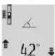
BctaHObTB BmIPBOBaHbH INCTpyMeHT,AK 306paKeHo HA MaIOHky, Y BmIPBOBaHy peKy (25) Ta 3aΦikCyIe TB BmIPBOBaHbH INCTpyMeHT 3a DOnOMoHO BaKeIaΦiKaJI (26).HaTCHITb KONIKy BmIPBOBaHHA (2),
üo6akTbByBaTnpeKHMpo60Tu «BmipioBaIbHa peKa.
PeryIrpHO nepeBipRte TOHcTb BmipOBAHHa KyTa Haxnny ⅢJXOM BmipOBAHH B O6ox HaprMkax a6o 3a DOnOMOrO BatepNacIB, 103hAxOJaTbCra HA BmipOBAJIbHi peuci.
Pn6iBbBENIKX BIXINHEHxNOTpi6HO 3HOBy BIDKANIPyBaTH BNIMIPBOAbHNI IHCTpyMeHT. YTPMMyTe DnIyCboTO KNKNY BHMIPOBAHK KyTIB HAXNY (3). BHKOHaTE BKA3iBKHaDcNneI.
Uo63aBepuHTpeKmpo60TH《BnMipIOBaJIbHa peKa》,BMMKHITb BmIPIOBaJIbHHIhCTpyMeHT Ta 3HIMITb HOrO 3BmIPIOBaJIbHOIpeKN.
Hecnpabhocti -PnpuHHi ycyHeHH
PnunHaUcyneHHa
BnMaic iNdkatop BHXOy 3a MexKi tempepatyphoro diaana3ohy (j), BmipioBaHH HeMOxHBe
InukauiaEERRRHaHnCnnei
B6yObaHia akymyIaTOpH 6aTaPei Jo3BONeTbCBAHIMaTHn HneΦaxIBaum I nHeu yTHInIaJI. IIkPbBaHHIOshINBKN KOPNcYMOxNBE NOIKoJKeHHBAHIMPOBaIbHOrO IHCTpyMeHTA.
UoB BnHHTn AkymyIaTOpy 6aTapeo 3
eNEKToPiHCTpMeHa, BnKOpHcTOByTe eNEKToPiHCTpMeH
do Tnx nip, noKn akymyIaTOpa 6aTapeR NOBHCIO He
po3paNTbCBAkpyTITb RbHTn Ha Kopnyci i 3HIMtB
obONOKy KopNyca, UoB BnHHTn AkymyIaTOpy 6aTapeo.
UoB yNHKNHYn KOpOTko 3amNkaHH, Bi'EDHaNe To cepa
BCi 3EHNHn AkymyIaTOpa i 3aiOnIOte NOnOcN. HabItb
PnnoBHOmy po3prJKeHHI B akyMnyTOpHII 6aTapei ue MicHTbC3aJIuWkoBA eMHICTb, RaKMOxE BUNBbHITNCpN KOPOTKOMy 3amKaHHi.
Ka3ak
Eypa3nЯ 3KOHOMHKanbIK OdaftbHa (Kehen OdaftbHa) MUpe MemNeKeTtep aymarfbHda KOnDaHbIaDbI
HdyinH yHkapactbipfah naDanahy KxattapbHbKypamblnaaDanaHy XeHnderiOCb HcayblbcohmenbipreKocbImanapdaBonyMymki. Caikekti pactay kainblaknapatKocbIMwada bap. OHdiprehmMemleketTypablaknapatEHMHIN KopnycbHdaXheKocbIMwada Kepcetiren. OHdpireh Mep3imi Hcyayblk MykaacbHbH coHfbl beIHde xHeOHmkopnycbHda Kepcetiren. HMnopTreKaTbctbbaNaHbcaknapatEHIM KaTAMacblHa Kepcetiren.
Ehimi nai danahy Mep3iMi
HIMHHKbI3MeTetyMep3iM7KbI. HdipinreHmep3imHe6actan(eHipy KyHi 3aybIT taKaTHwaCbIHda Ka3bIFaH)ICTeNe5 KbIcakTaFahHaH coH, eHIMDi TEkcepCi3 (cepBnCTIK TeKcepy) naDanaHy CbIHbIMaDbI.
Kb3MeTKeHeme NaaHaHybHbH KATENIkTepi MeiTe Hbry ce6entepinTi3imi
-ehIM KOpnycbHAn TikeNe TytIn 7bIKCa, naJaIaHa6aHb3
JaybH-1aWbHKe3iHDe cbiPTa(daIada) naDanaH6aHbI3
-Kopnyc iWHe cy Kipce KpybInfbHbKocyBb60MaHb3
Uekri kyn 6enrinepi
-0HIM KOPNcBbH3aKbMdanybl
Kb3MET Kepcety Tpyi MeH Xniniri
O npaIandaIaHydAncoEHIMiTa3aIay yCbIbIaNbI.
CaKray
KypfakkepecaTayKepek
JXOFAPbI TemnepaTypa K03iHeH XaHe KYN CaynepePiHi, acepiH en anbc caKtay KepeK
- cakay Ke3iHne TemnepaTypaHbIH KeHeT aybITKybiHaH KOpFay KepeK
-erep Kypan KymcaK cEmke HeMece nactK KeiTe KekT3iNce OHbl Ocb 03HIN KopFaBbIa Ka6bHda caKTay YcblHbJaBbl
- cakay単apTApbl typabl kocmbua aknapaTanyuH MEMCT 15150 (単apt 1) KyaKaTBn KaPahB3
TacbImaJay
-TacbImaIay Ke3HHe eHIMDi Kynatyfa XHe Ke3 Ke nreH MExaHKnAblk bKnT aTe rKaTaH Tbblm CaNbHaDbl
206|Kaazak
-6ocaty/JyKTey Ke3iHne NaKeTI KbICaTH MaUNHaIapDbI naDanaHyf pyKcat 6epinmeiDi.
-TacbImaJay単apTAPbl TanaTAPbIH MEMCT 15150 (5単apt)KxKaTbIH OkbHbI3.
Kayinci3ik HycKaynapbI


Ouwe Kypalbmeh Kayinci3 Xane cemimTiype Jxmbic ictey yuiH 6apnbK HcckaynapdbOkblOpblday KepeK.
Onwe KypalbH OcbI Hyckaynapra caa nainanah6ay
onwe KypalbHdArbl KipikTipinreh Kayinci3dk
wapanapbHa XafBIMcbl3 ocepe tedi. Onwe
KypalbHdaFle ckeptynpdi ew xafdaia
Keipinbeintiend erneH3.OCbl HYCKAYAPDbI CAKTAN,
ONWE KYPALbIH BACKAIONPFA BEPTEHDE ONAPDbI
KOCA YCbHbHbl3.
A6ai 60nbHb3 -erep ocby xepde 6epinre H naDanaHy Hemece ty3ety KypanapbHah 6acka KypanDaH naDanaHca Hemece 6acka kymbic aictepi opbHaIcA 6yn Kaynti caynere wAnbHyra anbin Kenyi Mymkin.
Onuey KypanbIe cckepTy TaKtacBIme 6ipre KeTki3inRe (enuey KypanbIHbH CypetInHe rpaFnka 6eiHne (20) HmipimEn BnirineHre).
IEC 60825-1:2014 <1 mW, 635 nm
Laser Radiation Do not stare into beam Class 2 laser product

Erepckeptyxancbipmacbi ci3iH eniH3 tiniDe 60nmaca,anfawkbniadanahydaandbih OHbIH opbHa ci3iH eniH3 tiniHde 60nfraXncbipMaHbI Xa6bictpbHbI3.

Ja3ep caynecih aam Hemece XaHnyapnapra 6aftTamahbi3Xe3i3de Tikenei Hemece Wafbnfah Jaep cayncie KapaMaHbI3.Ocbna aamdapdbIH Ke3IH
UaFbIbIbpyMbMYMKiH, cTcI3 OKnFaIapra anbl Kenyi KKeHKe3d3aKbIMdaybMyMKiH.
ErepnaepcayneciKe3reTycceKe3depjixymbln 6actbcaynepehapbkaparykepk.
Na3ep KypbInfbicbHda eukHaan dE3repty opbHdMaHb13.
Paepeepeep
cayncin kakcbipak Kepy yuH Kbi3MeT KacaIbI, 6ipak on naep cayncineH Kopfamaibl.
P3ep Kepy Keinipirih Kyh Keinipiri petiHne Hemece Xon Ko3raBcHda naDanaHbI3. P3ep Kepi Keinipiri ynbTpaHnonet CaynepeHtOnbKopram peH Kepy KaBnTeH a3aTadbl.
Onweky KypanbH TeK 6iikT MAmHaFxAhe apHaynb6wnwekTepeMeH XeHdetin3. Con apKbInb EJwey KypanKayinciairH caKaTaNb3.
Bananap na3ep enwey kypanbH 6aKbInaycbI3 naDanaan6acBH. Onap 6inme aamdapdbH Ke3IH waflblcTbpy MymkH.
KhaHbIH cybIKbIKTap,ra3ap Hemece WaH KhbINFAH Xapblnc Kayni 6ap optada enwey KypabHn naDanaHa6bH3. Enewey KpaBly uWkbH UbIfapbln, WAnDbI KaHdbpbln, ept TydbpybMyMKH.

Onuwe Kypabih bictbikTah caKaTahbi3, XHeMbicabi, y3ak KYHde TpybHaH, anaydaH, cy XHe bINFaIbIbIKaTah.
Kapbny kayni 6ap.
Onwey KypanbH TeK canbIHraH MHkpo USB ka6enimeh 6ipre naDanaHbHbI3.
3apayay Kypanapby ywiH Kayinci3dk HycKaynbikTapbl
6aIapTay KpaIbI 6aIapDbIH, DeHe HEmece Oi Ka6ineTepi WeKTeIReH, Toxnpi6eci Xane 6bnimi a3 aamapdbIH naJaIaNHybHa apHaMaFAn. OcbI 3apTay KpaIbIMeH 8 JactaH acKaH 6aIapDbIH Xane DeHe, ceIm, onlay Ka6ineTepi WeKTeIReH He Toxipnbci MeH 6inimi a3 aamapdbIH KyneHi Kayinci3 naJaIaNHy TypaIbI HycKaycbI3 XHe XayantbI aamHbIH 6akblaybIHcbl3 NaJaIaNHybI aca Kayinti. Kepi KaFaJaIda Dypbc i naJaIaNbEy XHe XapaKaTTaHynap Kayni naDa 6oIaBl.
Падалану,Та3алayжэнeКызMet Kерсету Ke3iHne 6anapra
MkyT60nbHb13.BaIanaPdbIH 3apTay KypalbMeH OHaMaybHa K3 XeTKi3iH3.

3apTay KypanbH XaH6bpDAn Hemece
binfandbikTah Kopfahb3. 3neKtp KpaBHBiH iWHe cy Kipce, on 3neKtp TOfbHBiH COFy KayniH apTbipabbl.
Oneyey KypanbIH TEK XHHaKTarbl 3aprTay KypanbIMeH 3apraTaHbI3.
3apnay KypanbH Ta3a Yctahbl. KypandbH nactaHybl TOK COYbyi KayinIH TybHaTaBbl.
Op naDanaHydAn anbIn 3aprTay KpaBnH, Ka6enbIi Xhe aInpNbTeKcepiH3. Akaynb 6aikacah3 3aprTay KpaBnH naDanaHaBn3. 3aprTay KpaBnH e3in3 aunhaBn3, Ohbi TEK 6iniKTi MaHa FxHe TynHcyKaNbl 6eWekTePmeH XeHdti3. 3aKbIMDaJFaH 3aprTay KpaBnL, Ka6enb Xhe aInp 3neKtp TOfbHbN, CORY KayniH apTTbPaNb.
3apntay KpaBnKocynb Kynde OHaJXHaTbH 6eTepin (Mbicanb, KaFa3, Mata Xhe T.6.) yCTHe KOImaHbI3 Hemece XaHbIi 3aTTapDbH XaHbIH naDanaH6aHbI3. 3apTay Ke3Inde 3apTay KpaBnHbN KbIaby Ce6beHEn ept Kayni naDa 60anbl.
AkkymyTOp 3aKbIMdaHFaH HeMece OHbI dypbc NaDanaH6aHaH XafdJa 6y WbIFybl MymKiH. By XaFdaJa iWke Ta3a aya Kipri3iH3 XHe WaFBMdap 6o1ca, MeduINHaBik KEmek AblHbI. Bynap TBHbIC any KOJdApBH TITIPKeHdipy MymKIH.
Θhim xəHe KyaT CnnaTTamacbl
MaKcatb6oynbHwa konDaHy
Onwey Kpaanb KaBbIKbTbKapdb, y3bHDbIKapdb, 6nkiKTEpdi, apanbKTapdb, kon6eynepi Onweyre KaHe aydah Meh aymakTapdb ecenTeyre aphanFaH.
Onweky KpaIb iKl MeH cbIpKbI aMakTapda naJaNaHyFa apHaIraH.
KopceTinreH KypamDbI 6eNeKTeP
Kpcetinre Hcpamactap hemipi rpaoka 6etihderi enwey KpaanbHbH CnattamcbHa KaTbCTb60bn Kenedi.
(1)Диспел.
(2) Θιηώγτυμεῖ
(3) Kənbeyni enwey / kən6bpny tymeci
(4) ΦyHKUHbI aybcIbpy/ Heri3ri peTReyep Tmec
(5) MHHyC TymMeci
(6) HToNke / TaHMeP yHKUncbTyMec
(7) Θnwey mHaDepi / kAaTbH TpyaKTBmHaDepi TyMeCi(A)
(8) KaTbI eWipI rYmeci / Kocy-eWipI rYmeci
(9) Ⅲtndftini TipeK
(10) Heri3ri kja3bIKtBkTb TaHday Tymeci
(11)ΠIOCTYIMecI
(12) ¥3bɪnɒblɪk, ayən Mæn Kənemʌj eŋlwey Tɪmèci
(13) 3apraTay YacbHIn KaKnaFbl
(14) MmKpo USByrcbI
(15) Bay 6ekitkiu
(16) Naape cayncinH WbfbcB
(17) Ka6bInaynH3acB
(18) CepnIbIK, Hemip
(19) 1/4 duoiMdiK 6ypaHda
(21) 3aayTay wTekepi
(22) Mнкpo USB ka6eni
(23) 3apadTaftwiKypblfB
(24) KopfaiTbH KaTa
"Heriari petreyep" m3ipi
"Herizi peTeynep" M3apihe Kipy yinH Herizi peTeynep Tymecin (4) 6acbin TypbHb3.
Heri3ri peTeynep Tymecin (4) 6eNkM3ip TapMaKTapbH TaHday yuH KBCaHa 6acbHbI3.
MnHyc Tymecin (5) HEmce nIOc TYmecin (11) 6acbIn, M3ip TapMaKTapbHbH iWHe peTeyi TaHaBb3. "Herisi peTeynp" m3piHen ybiYyih enwey Tymecin
(2)6acbHb3.
Herisri perreynep
IbIbIcIbIK CnIHanJaK Kocy

Θwipy
Jncnnne JkapbifKocy

Owipy

ABTomatbly Tpyde Kocy/ewipy
CaHbIK Batepnap Kocy

Uwipy
ДиспennialаинayыКocу

Owipy
Y3dikci3 naep cayneci Kocy

Owipy
KaawbIKbIK 6ipniri (3KCNOPTbIK HYCKa 60nbIHwa)
M,ФуT,IIOHМ,...
OIIwey MaHI HAtnKeIep KOnaFbHna (c)
Kepcetinei.
Biphewe y3bHbK eWey apeKeTih opbHaFaHda, coHfbl eWey HATNKeIepi eWey MHepePiH XOJaFBHda (a) Kepcetinedi.
AydanaDbie onwey
AydaHdbI enwey yuHIN 12 TYmecin dncnneJe ayaHaDbI enwey HndKATOpbI naHa6oNfAHa6aCbHb3.
Cohah coh ehi meH y3bHdbfBn dAeKeTI Tpye 3bHbIKTbI eIwehen enweeJ3. Eki enwey apekeTinapacbHa da naep cayneci kocynbl 60bn Kanada.
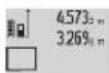
Ekinui enwey opekein aarktafahn H Kein, ayanabTOMaTTbI type ecentenin, hntnxenep JOnaftiHa (c) Kepctinei. BneK enwey mHepi enwey MAnepiHIn jonakTapbHa
(a) TyaDbI.
Koenni eonwey
KoNemDi OJwey yuH (12) tyMecin DnCnneJe KOnemdi OJwey HndNKATOpb naJa 60nFaHa7a 6acbH3.
Cohah coh eHH, y3bHdbfBn JxHe TepeHdiin daiKeTt typde y3bHdbKtbl enWereHneenweHia. Yu enwey apeketHH apacbHa naepcayneci Kocynbl 6bn Kanadbl.
YuiHni OniyeDi opbHaFaHaHaH KeiH,KeIeM MHi ABToMaTbI Type ecTeIn, HAtNKeIep KOnaFbHJa (c) KepCetineDi. BeneK enWey MHepei Onwey MHepePiH JxolaKaTpbiHda (a) TypaBl.
999 999 M³ WAMacbHaH apTbIK MAnHep KepcTeIImMeNdi, DnCnneJe "ERROR" Ka36acbI NaJaDa BOnaDbI. ΘIWeHETIH KOnemDi 6oNEK ENoWey ApeKeTepine BEni, MaHepin BOnek ecenTeH3 De, COnaH KeIN KocbHbI3.
¥3aKtbIbIbI ΕιλeY / MmHmMyMbI / MaKcHmMyMbI ΕιλeY (B cypetin KapaHbI)
¥3aKbIKbIeNwey Ke3iHe eNwey KypalbH HbCaHaFAr
KbIMKbITyfa 60nab, coHa dNwey MmHi WAMMaMeH ap 0,5
ceKyHd caBnH KaHapad. MbCaNbI, KaBipraDaH KaKeTTi
KaIbIKbIKKa DeHH aNbCTayfA 60nab, afBIMdaFl
KaIbIKbIKApdaHbIM KePiHedi.
¥3aKbIKbIeNwey ywH cyHKUINHbI aybIcTbpy TYMecin (4)
DcCnneJe dy3aKbIKbIeNwey HNDNKATOpbi naJa
6oNfAHa 6acBHB3. ¥3aKbIKbIeNwey apeketih bactay
yWIn OJWeY Tmecin (2) 6acBHB3.
MHHMymdbI eWeyTypakTbI Heri3riHyKTeDeHekkKa KaabkbTbIKTBtOeWeyyWIn Kbi3MeTeEdi.0nMbicabI,TKKHe KeJeHe KaabkbTbIKTapdbI eWeyre KEmekTeCeDi.
21|Ka3aK
MaKcHymMbIe enWey TypaTbI Heri3ri HkyTeDeEH y3a KaBbIKbIe enWey yWIn KbImETeEi. On, MbicabI, dnaRaHaNbDi KaBbIKbITapDbI eWeyre KeMeKTeceEi.
HtHexenepKoNaFbHda(c)afbIMdaFbEnIwey MHI Kepcetinei. OIwey MHepePiH JKOaFbHda(a) MaKcHMaNDbI ("MaKc") XeHE MNHMaNDbI ("MnH") OIwey MHi naJa 6OanDaI. AFBIMdaFbY3bHbIKTb ENIwey MHI
aIbHbIMMHMaIbHEmee MaKcHMaJIbMHaHHEN KEM He mee apTbK 6oIfAHa, on aPdaiBIM KaTa Jka3blaBl.
JaaTbI eipy TyMecin (8) bacy apkbla anblHfbi
MHHMambl HeMeCe MaKcHMaIdbI MHeep KOnblnabI.
Y3aKTbIKbI eIwey apeketih aRtay yuiH eUwey TyMecin
(2) 6acblb3. CoHfbI eIwey mHi HHTNKepep KOnaFbIHda (c)
kepcetinei. OIwey tyMecci (2) KaHaTa 6acblfHa,
Y3aKTbIKbI eIwey apeketi KaHa Tcke KocblnabI.
Y3aKTbIKbI eIwey 5 MHHTTah KeHH ABTomatbl TyPe
eWei. CoHfbI eIwey MHi HHTNKepep KOnaFbHda (c)
kepcetinei.
KaHama KaWbIKTbIKTbIOniwey
KaHama KaWbIKTBKtBteIeWey FyHKUncBc Cayne KOnblHa Kaepri BonFaHda Hemece KaTAPBw peTIHe MaKCaTTa Ka3bIKTBK KonKetIMdi BonMaFAHda, Tikeen eIeHBeHTi KaWbIKTBKapDb eIeWey yuH KOnDaHbIaNdb. Bye IeWey npocecin TK TIK 6aftTa naidanaHyra bonab. KeJeH e6aftTaB ap ayltky onwey kateNikTepi tydbipabI. OIwey apeKeTepiH apacbHa na3ep cayneci Kocynbl Bobn Kanadbl.
Kaawbiktbkbl enwey yin haptyni Kaawbiktbknapdbenweyreymkmhik6epetihw enwey fyHKnncb6ap.
a) KaHama 6nIKtKi eHwey (C cypetIH KapaHb3)
Функинblaybctbpy Tymecin(4)nncnneJkeKaHama 6niktki enwey mdkatopb naJa 6onfana 6acbHb3. Θnwey KpaIbHbTtemeHri nwey HkTeimeh 6ip 6niktke 6onfaHbHa Ke3 keKti3iHa.Coah Kein enwey KpaIbH Her3rJx3bIKbTKaTH KaibpIn, Y3bHbIKbTbnWeReHeJ KaWbIKbIKtB1 (1) enWeH3.
Onwey aKaTaNFaHHaKeiH, i3enreH "X" KaBbIKbIbI yuH HAtNke HtNKepe JOnaBbIHda (c) Kepctinei. "1" KaBbIKbIbI MeH "d" bpybIbHbH eJWey MaHepi Onwey MHepeiH XoNarblHa (a) TypaBl.
b) Koc xahama 6nikrki Te nwey (D cypetin kapaib3)
Функци�нbl aybictbipy TymecinH (4)mncnneKOC JkaHama bniiktikti oniwe uy Hndnkatopbl naJa bOJFaHwa 6acbHb3.
"1"XaHE"2"KaUbIKTbIKTapBHy3bIHDbIKTbIOnWereHdeOcb peTTinik BoiBuHua OJueH3.
OJwe ayktafHaHH KeiH, i3denetih "X" KaIbIKTbIFyUHH HtNKe HtNKepe JOnaFbIHda (c) Kepctinei. "1", "2" KaIbIKTbIKTapbi MeH "a" 6ypbluBHH eJwe MAnepi enJwe MAnepinH xonafbIHda (a)
TypaIbI.
OJyHnHeri3I Jx3bTbFbMbicanb,0JyKpabHbHapKbJxneri 6apBbK eJnye apeKeTepinderJe enJyepnoecinH 6apbcihda typa bip jepde 6onFaHbHa Ke3 KetkiH3.
c)KaHama y3bHdbkTb eHwe (EcypetIH kapaHb3)
Функцинbl aybctbpy Tmecin(4)dncnneJxHaHama y3bHbKtbl eWey HnNkATOpb naJa bOngFaHwa bacbHbI3. ΘWey KypaBbHbI i3eTReH eWey HKyTeCimEH 6ip 6nIKTKte BOnFaHbHa Ke3 JeKti3iH3. CoaH KeiH eWey KypaBbH er13rI Xa3bKbTKaTH KaBbPbIn, "1" KaBbKtblfblH y3bHbKtbl eWereHdeE nWeHiz.
OJwe ayKaTaNFaHHa KeiH, i3eIreH "X" KaBkTBfBi yWIn HAtNXe HtNXeNep KOaBkBnHa (c) Kepctinei. "1" KaBkTBfBi MeH "a" 6pybMbHbH eJWey MAnepi eJWey MaHepiH JKOaNbHda (a) typaJIb.
Ka6bipyraaydaanbHnOnwey(FcypetinKapaHb3)
Ka6bIpaaydaHbH eHwe 6ipHewe Jannb6nIKtIKI 6eNek aydaHapdbH KocbHbCbH ecNTey yuH naJanaHbIaNb. Kepcetireh Mbicanla A 6oNe 6nIKTiri 6ipDei, 6pAK B y3bHbIbI aptypni 6onatbH 6ipHewe Ka6bIPaHbH XaNNb b aydaHb ecenTenei.
Ka6bIpa aydaHbIn eJWey yuH cyHKUINHBaYbCTbpy TYmecin (4) nCnneJe Ka6bIpa aydaHbIn eJWey HNdkaTOpbl naDa 6onFaHsa 6acbHb3.
A6bnme 6nKtirH y3bHbKtB t enwee Hne enweH3. 0nwey mHi("cst") KOFAPfB t enwey MAnHHXoNAFBHda (a) Kepctineni. Naep Kocyn b Kynde kanaab.
CoaH KeiH bipHki Ka6bipFaHbIH B; Y3bHbIbHbIbnEWeHiz. AyaH ABOMATTbI Tpye ecentenH, HtNKepeKoNAfbHda (c) Kepctinei. CoHbI y3bHbIKbTb EneWey MHi optaHbI eWey MaHepinH JKOaNfaHda (a)
TpaIb.Ia3ep Kocybl KyIe KaIaIbI.
Ehdi ekihui Ka6bipraHbH B2y3bHdbfHb HneHie. OptaHfb eHwe MHaepinH K0naFbHda (a) Kepcetinre Hnwe MHi B1 y3bHdbfHbHa KocbinaDb. Eki y3bHdbKtBb H KocbHdbcI (sum" TMeHri eNwe MHiH
KoNaFbHnDa (a) KepceTirHe) caKaIraH A 6niKtiRiHe Ke6eTInedi. KaNbl aydAmH MaH HAtnxKepe KOnaFbHnDa (c) KepCetinei.
Ke3 KeTReH 6aCa Bx Y3bHbIKapBn EneWeyre 6oNaIbI, onap ABToMaTbI Type KocblBn A6nKtiriHe Ke6eTinei.
Dpybc aydaHbI ecnteyiH anfbiWapTbI -6ipHwi enWeHreY3bHbIKbIH (Mbicanbl, A 6enme 6niktiri) 6apnbK 6eneKaaydaHap yuH 6ipde60nybl.
KoIeeyi ewey (G cypetin kapaHb3)
Kenbeydi eJney Tymecin (3) 6accabis, nncnnepe Kenbeydi eJney HndkaTOpbi naJa bOanaB. Herizr i Ka3bIKbIK petiHde OJney KypalnbHbH apKbXaFbl KondaHbInaDb. Kenbeydi eJney Tymecin (3) Taftbipet bacy apkblbE Jney KypalnbHbH 6yipniK kaa3kbTbKapbHer13ri kazakTBk petiHde KonaHaBbIn, dncnneKepiHici 90"uamaCbHa 6bpbnFaH Kynde KepcetineDi.
Onwey TuMecin (2) 6acbin, enwey MAnH 6ekitih3 XHe enwey mAndepinH jAdbHa KewipiH3. Onwey TuMecin (2) Taftbipert bacy apkblb enweyyi kAnfactbpyra 6onabI. Onwey npocecinh 6apbcihda HnHnKaTOp XblnbKTaca, 6yn onwey KpaBbHbH 6yipineH KaTb aydpaBnFaHbH 6innipei.
Herizpi pTeeynepe "CaHbIK Batepnc" cyHKunrcbKocBnFaH 60cnca, Ke6ey mHi baca eIiwey fyHKunapbIHda da HcneH (1) (d) KOnaFbIHKepcetinei.
TaimepyHKnHcbl
TaHMeP cyHKcncbI, Mbicbl, enlwey Ke3Hne enlwey KypalbHbN KO3FaBICTapbHa Kon6bpMeK KaKeT 60nFaH KaFdaJa KEmeKTeceni.
TainmepyHKnncbIyuiH (6) TmMecin DnCnneJe 1 HnKAtOpbI naJa 6oNfAHa7a 6acBIn TypbHb3.
OJHey MAnepiHIN KOnaFbIHnA (a) icke KocblnydAn OJIeuyre deHHri yaBt apanbIbI Kepcetinei. YaBt apanbIFbH NIOc TYMecIH (11) HEmec MNHyC TyMecIH (5) bacy apkblbl 1 c Xane 60 c apanbIfbHa peTteyre 60anabl.
PetteneyakbIapabibfTekeHHKeHH, eHweABOMaTbITypeOpbHdaJaB.
TaMepyHKnrcbH6acka eJwey yHKnnapbHbH iHderi KaBkTktb
enweyapekeTepinde(Mbicanb,aydAndbenwey) naaIaNHyfRa6oIaDb.Enwey HtNkenePiKocyKaHe a3aTy KHe y3aKTbIKbIeWeyMmKIn60nMaHbl.
CoHfbI onuwey hatoxkepeinH ti3iM
Oney KpaIbI coHfbl 20 enwey MmI MeH onapdbH ecTeMepeH caTan, onapdbI kepi pettinik BoBihwa KepceTei (coHfbI enwey MaHepi eHbacHna).
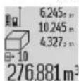
CaKaTaNFaH eNwey mAnepin WkBipy yWIn (7) TYMecin bAcbHbIa. DnCnneIe coHfbI eNwey HAtNXkei, FHN eNwey MAnepin HtiImine apHaNFAH HnDkaTop (e) XHe KepcTeINre HnWeMdepNi HmipNeye aPhaNFaH KaOpHbI
naianda6oana.
(7)TMyMeciH KaTa b6acKaH Ke3e eWkaHaai 6aca
0IWeMdep caKaTaImaca, 0Iwey KypaIb coHfbl 0Iwey
0YHKUncbHa KaTbIn opanaDb. 0Iwey MaHepiH
Ti3iIMHeH WbIKKaHa, 0Iwey 0YHKUnaPbI TYMepePiH
6ipH 6acBb3.
AfbIMdaftyaykTTaKcpctiTReH y3bHdbIKTbOJWeyMmIH TpyakTbMnpeTHe caKTay yuHmJey MAnepi TzimHi Tymecin7) nncnneJe "CST" naJa 6oFaHsa6acBn TpybH3. OJwey mHaepi TiImHH Ka36acBn KeHH TpyakTbMn peTHe caKTayfa bOnaBl.
Y3bHbTbEneWeyMaHHeWeyyHKnucBnDaMbCaNb, aydaHbEneWey)naDanaHyuHIneWeyMaHepiTiimHi TYMEcIH76acbH,KaKeTTka3BaHbTaHaDaHb3KHe HtNKe TYMEcIH6bacApKnIpaTaHbI3.
OnweyMaHepinXo
(8)TyMecin Kbckaa6acy apkblb6apblk enwey cyHKnnaapbHa coHfbcenTrenre 6eNEK eIwey MmIH KOFOfa 6oana. TyMe 6ipHeWe pet Kbckaa 6acblFaHda, 6eNEK eIwey mAnepi Kepi pTTINIK 6oBHxa KoBlnaDb.
AfbIMdaBfYakbTTaKOpceTINReH eNlwey MAnHepeTI3iMInIH Xa3bAcBH XOIO YWIN (8) TYmecin KbickaWa 6acbHbI3. ByKIN eNlwey MAnHepeHH TImIH Xahe "CST" TypaKbI MaHIN KOIO YwIH eNlwey MAnHepeTI3iMInIH Tymecin (7) 6acbin Typbn, dAN CON yAkBTTa (8) TYmecin KbickaWa 6acbHbI3.
Ka6bIprA aydaHbH enwey fyHKunncbHna (8) Tymecin anfau pet 6ackaH Ke3de, coHfb6eneK enwey mHa, ekHwi pet 6ackaH Ke3de, 6apNbIK Bx y3bHbIKTapbl, an yuHwi pet 6ackaH Ke3de, A 6nme 6nikTiri K0nbnaDb.
OneeyMaHepinKocy
OJwey MAndepin Kocv yiw andbimEn Ke3 KeIreH eJwey
apeketih opbHaanbHc Hemece oJwey MaHepinH TiImineH
Ka36abHb TaHdahB3.Coan H KeiH nKc TymecicH
6acbHb. DnCnnepe pactay wH "+"" naJa 60anaB.
Coan KeiH ekHHe Jwey apeketih opbHaanbHc Hemece
eJwey MAndepinH TiImineH Ka36abHb TaHdahB3.
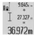
Eki eIweyIH KocbiHbICbIH WaKbpy YwIH HtNKe TymeciH (6) 6acblb3. Ecentey eIwey MHepeHH KOnaFbHda (a) KepcTeinei, an KocbiHbI HtNKepe KOnaFbHda (c) TypabI.
KocbHbceTtenrenHeKeiH,EnweydeH6pybHnnOc tyMeci (11) 6acblnca,ocbl HtNkEe KocbMua enwey MAnepin Hemece enwey MAnepi T3imHnKa36bnapBn Kocyfa 6oana. Kocy apeket HtNke tyMeci (6) bacy apkbbl aKaTanaabl.
Kocy boiHua Hcyaynap:
-¥3bIHbIK,ayaH MeH KeIeM MHepeiH apaIacTbIPbIN Kocy MyMKIn EMc. Erep,MbICaJIb,6ip y3bHbIKxHe 6ip ayaH MHI KcBILCa, HtNKe TyIMec (6) 6acBIFaH Ke3De, HcIeNeIe "ERROR" Ka36acblKbICKa MEP3IMre naJa 6oJaNbCi. CogaH Kein eWey Kypanbl COHfbl 6enCeHdi 6oJFaH eWey fYHKUINCbHa ayBCaJIb.
Bip enwey hntxekci (Mbicalbl, Kelem MHI), y3aKtbkTbI enwey kezihne HtNKeJep XonafbiHda (c) Kepcetinre Hnwey mHI Tnicihwe Kocbinabl. Owey MaHepin HXonafbiHah (a) 6eneK enwey mHepeiH Kocy MyMKH emec.
OneyMAnepinany
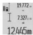
OJney MAnepin any yWIn MNHyc Tymecin (5)Hcnnnepe pactay petiHne -" naJa 6oNraHua 6acbHbI3. KeiHi rpeKeTep "Onney MaHepin Kocy" npoueypacbIme 6ipJeB60nAbbl.
PaiDanaHy 6oBihua HycKaynap
KannblhycKaynap
Ka6binyHnH3acBn(17)xHe na3ep cayneciHH bIfbcBn (16) eey Ke3iHne xa6yfa 60MaJdbI.
Onwe KeiHne enwey Kypabn HxblNkbyTfya Tbblm caHbHaB (y3aKbIKbEwey KHe KeIbeydi enwey fynKunapbn HocnFaHaDa).Con yuiH enwey Kypabn H MyMKinirihwe Typakbl TipeK HeMece 6ekiry aMafbla H KOybHb3.
214|Ka3aKa
Onwe Dnana3oHbHa Thetin ocepne
OJIeY dana30Hb JapbIK KaFdaNb MeH MaKCaTTb
Ka3bIKbKTbIH KaTApFbITbIFbHa 6aJIaNbICtB.CbPTTa
Kymbc icTey Ke3iHe JeAHe KaTbI KYN JapbIFbIHdJa3ep
CayncinHKepepniRIN XaKcaptY yWIn Ja3ep Kepy
Ke3indipirin (28) (Kepek-KapaK) XeHe Na3ep HbICaHbIK
TaKTacBH (29) (KepeK-Xapak) NaIdaNaHbIH3 HeMece
MaKcaTTb Ka3bIKbKTb EwipipH3.
AnikTeKcepyKeHKeN6eyeNweydiKaHbpey (H cypTeH KapaHbI3)
Ken6euyi enwey dndirin kyyeni type Tekepin typbHb3. Byn apeket kepi enwey apkblbOpbHdanyb MyMKIN. On yuHn enwey KypalbH ycTe nre KoBIn, Ken6euyi enweHiz. OIwey KypalbH 180" uamacbHa 6ypan, Ken6euyi KaTadaH enweHiz. Kepcetiren caHHbA aibipMaublbIfbE h Ke6i 0,3" Kypaybi Tnic.
YkkenaybtkynapdaenweyKpaBnKaTaNINbpney kakket6oana. On ywni Kenbeyni enwey Tymecin (3) 6acbinctaHbI. DncnnneDerinyckaynapdbOpbHaHbI.
KaabiktbiktbI enweyin dndirin Tekcepy
Thuey KypalbHbHdAndiH TeMeHderiJeTeKcepiH3:
-Дэл y3bHbIbI cIre 6enriri, y3ak yakbl t3epeMeTIN, WAMAMEn 1xhe 10 m apanlfbHdAfbI y3bHbIKKa ne OJwe KaBkTBfBnTHaHaB3 (MbCaBn, 6ne me nEi, ecK caBnayb).OJwe KaBkTBfBf 6onme iuiHne 6onybKepeK, OJweYDIn MaKcTbI k3bIKTBfBf Teric KHe XAKCbI KaTapFbIb 6onyb KepeK.
- KaibkblbipinH keih6ip10 petonwei3.
BeneK oniemepin optaawa amamadah aybtkbye H Ke6i ± 2 MM 6onybkepeK.AndiKTKeHHipeK Typanay MymkiH
6onyu yuiH, eniwey mHdepinKa3bn anbiH3.
UtaTHBnENKyMbIc icTey (Kepek-XapaK)
IITATNBti acipece yikke KaBtktapbl eNwey Ke3iHne naDnAhyKepeK. OIwey Kypanb1h 1/4IOHMdk Hpek OIMacBImeH (19) WTATNBtIH (27) Hemece cTaNdApTTb foTO IITATNBtIH Xblam aImactbpy TaKTacbiHa opHaTBi3. OHbl Xblam anMactbpy TaTacbiHb6ekitki 6ypaHdcBIme 6ekitiH3.
TATNBnEH eWeyre apHanFaH Heri3ri Ka3bIKTBkTBI (10) TYMecin 6acy apKbNt TmciHwe opHaTbHb3 (HpeK OMaHBn Heri3ri Ka3bIKTBfbl).
Ouwe yinacbimEn kymbic ictey (I-K cypetrepin KapaHb3)
OJWey WnHacbH (25) KeI6eYdi OJWeyDIn DAn HtMkeCine KOn JekTki3y yiwin naDanaHyra 6oNabi. OJWey WnHacbMeK KaWbIKTBkTb EJWey MymKIn EMc.
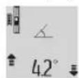
OJy Kypabn Cypette KepctinreHne JywnacbHa (25) ehrizn, OJyey Kypabn Kyblntay nhtiperimeh (26) Kylnta3. "Onywe ywnacbyKymbc peKcKcKoccy yWIn Hnye Tymecin (2)
6acblb3.
Kenbeyi eIeweyin dAndiin Kepi eIwey apkblnHe Mece eIwey uHacbHaBb BatepnaCTap apkblny KyyneI Typde Tekcepin Tpyhbl3.
YkKeH ayBtkynapda enwey KpaBn KaTaN KaNb6pNey KaKeT. On yuHIn KeBeydi enwey TYMecin (3) 6acbl YCTaHbI. DcnnneDeri HcyKaynapdbOpbHaB13.
"Onuwey uHaCbi"Kymbic pexkmiH aRkTay yin Hnuey KypalbH oWipin, OHbl nUwey uHaCbHaH TapTbIn 1BIfapbHb3.
Akaynap-Ce6entepi kheweiwimdepi
Ce6e6i Weimin
Temnepaypacckepryi (j) kblnbiktaib, onwey Mymki h emec
OJyIeKpyaBb-10CxHe OJIeY KpyaBbKymbc+50C apaBbFbHdaFb TeMnepaTpaCbHaKymbc TEmpePaTpaCbHa XeTKeHs Kytih3. Tbc (y3aKTbIKbEJIeY
fynkunacbHa +40^ 7amaCbHa deiH).
DncnneiDierrER"ERROR"HnIkaTOpbl
Opypi enwem 6ipnktepi Tek 6ipde enwem
He enwey mHepin Kocy/ 6ipniktepi He enwey
any MHepein Kocy/any
Ia3ep caynei MeH hbcHa Ia3ep caynei MeH hbcHa apacbHdaftb6ypblTbIM apacbHdaftb6ypblTbI cyip. yNKeIy
MaKaTbI K3a3bIKTBkTbIM Na3ep HbCaHbIK TaKtacBn KaTbI (MbCaJIb, aHa) (29)(KepeK-JkapA) Hemece eTe Haap (MbCaJIb, naJaNaHy
Ja3ep cayneciHH sbfbicbl (16) Hemece Ka6bIyday (16) Hemece Ka6bIyday
HnH3acbl (17) 6yNaHFaH nnH3acbl (17) KypFAKxHe
(MbIcAlb, TeMnpaTpyBHL H xMCak Wv6pekneh cyptin
Wyfbn e3repYHe). WbIFy
EcenTeIReH mH 999 999 M/ Θnwey npocciH apanbIK M^2 /M^3 IaMaCbIHAn apTbK. Kaamdapra beny
Ce6e6iUewim
Dcnnneieri ^* 60"HEmece 一 - 60^一 HnHnKaunacbI
Ken6eydi eIwey
Dnana3oHbHaH eIwey
fynkunrcbHemeceHeri3ri
ka3bIKTBYiwHacbpbl.
Enweydi6enrineHren 6byiAaMnAfBihBih iHInDe opbHaHb3.
Диспн徴eri "CAL"нemece "ERROR"нДИКaТоры
Kenbeydi eJneuydi KaHbpney Tnicti pettinikte HEmecTe Nticti no3nnaIapda opbHdAmdbl.
Kanibpeyapeketin
nncnnejerHemece
naDanahy6oBbHua
HYCKayIbIKTaFbHyCKaynapFa
caKeC KaTaNAb3.
Kann6pney yuHn
naDanaHbIHaH
ka3blkTbIKTap TIK KHe
KeIeHeHcBbIKTap
6oBbHsa dAn TypaHaH6aFaH.
Olnwey KypabI TyMeHi
BaKaH Ke3Je KByIbItbIbIbI
Hemece ToHKepiDi.
Kann6pnydi KcndeneH
Hemece TIK Ka3bIKTbIKTa
KaTanan, KaKeT 60nca,
Ka3bIKTbIKTapdbI
BaTePnacne H anDbH ana
TeKcepH3.
AkkymyTOp 3apdI DeHReHHINHnDnKaTOpbl (g), TempePaTy TpyaBle cckepTy (j) XeHe nCnneiDi er "ERROR" HnDnKaTOpbl
Onuwey KypaibHbH TemepaTypaCblpyKcata etinreH 3apday TEmepaTypacblHbH dnaana30hHaH TbIC
3apayay TemepaypacbHbH dana30bHa JekTeKHe KyTe TpybHb3.
AkkymyTOp 3apdIb DeHReinIH HnHnKaTOpbl (g) XaHe DnCnEneri "ERROR" HnHnKaTOpbl
AkkymyIaTOpdbH3apraTay KepHeyiDpybIcEmec
UTeTcNbDik 6aHaNbIc
DpybcOpHaTbIraHbH XHe
MnKpO USBKa6eni TniciHne
XyMbIC icTeReHH TeKcePi3.
KypblFb6enrici
XblblbIKtaca,6yn
aKKMyJrTopDbHakaynbI
EeKeHirH XaHe OHb Bosch
KbIMET Kepcety
opTaNbIfbIHda aImactbipy
KepektiriB 6inipei.
AkkymyTOp 3apdIbI DeHreHInH INHdkatopbl (g) KHe DnneNderi (f) Benrici
3apTay TOrbIHbIHbIM
TMeH 60nybHa 6aIaNbICTbl
3apTay yaKbITbl KaTTbl
y3apbl.
Tek Tynhycka Bosch MmKpo USB ka6eniH naDanaHbHb3.
Thneuy Htnceci Tycihikci3
MaKCaTbI Jka3bIKbIaHbIK KaI TaBbIMaHbI (MbICaJIbI, cy, eHNeK).
MaKaTtBtJka3bIKtBtKtJka6y
Ce6e6iUewim
Ja3ep CayneciH Hbifbcbl (16) HeMece Kbl6blnday HnH3acbl (17)Ka6blk.
Ja3ep cayneciHH bIbfcBH (16) HeMece Kbl6bnay nH3acbiH (17) aWy
HeriziXa3bIKtbkKate opHaTbIbI
OJUeyre XapamdbHeri3ri Ka3bIKbIKTb TaHday
Ja3ep KOnbIHda Keepri 6ap Na3ep HkyTeci TOnbIKTaMaKCaTTb Jaa3bIKbIKTa6onyblTnic.
HnHnKaunE3repMeTyp Hemece enuey Kypalb tyMeHH6acbinybHa KyTINmeren Xayan KaTapaabI
BaIapnamabIKKaacKaTamaakaynbflbl
OJUeY TYMecin (2) XaHe KaTbI eWipy / Kocy-eWipy TYMecin (8) 6ip yaKbTTa 6acbl, 6afDapnAmJIbIK XacaKaTamaHb 6actanKbl KYrE KaTApBbH3.
Onwey KpaBb ap6ip enweyin Dpybc opbHdanybH 6akbnainb. Akaybnk anbKTanca, dncnneTeK iprenc 6enri Kepcetinei. Myndai kafdaHnA Hemece Kofapbda CnatafAH KEMek Wapapanabi
akaynbiktbjxhoora KEMeKTeCnece,Onuey KypanbH dInepi3apkblBosch KbImet Kepecy optanbfiba Ka6epi3.
TexHnKaIbIK KyTIM XHe Kbl3MeT
KbI3MeT KepCeTy XeHe Ta3anay
Onuwey KypanbH TEK KEtkiinreH KOPFaTbH Ka6bHda CaKaTaHb3 HeMeec TaCbMaJaHaB13.
Thneuy KypaibH Ta3a YctaHbIa.
Ouwe KpaJIbIH CyFA Hemece BaKcA CytbIKTbIKTapFa 6aTbIPMaHbI3.
JtacTahynapdbcyaHFaH,JyMcaKwyBepeKeHcyptnia. KYfbls3aTnapdbHeMeceepiKiwTepi naDanaHaBla3.
Ka6binyHnH3acBn (17)Ke3inDipik Hemece potoannapa nHHacBkyTIMHde KyTHiJ3.
KeHneyKaKeT 6oIraHa, OIuey KpyanbIH KopFaITbIH KaTacbHa (24)Ki6epiH3.
TytbHybIfa Kbl3MeT Kepcety XHe naIdaIaNy Kehectepi
Kb3MET Kepcety optaibfbi eHimdi xehney khe OFAH
TEXHKAIBK b3MET Kepcety, coHdA-ak Kocalkb
6eWekTep typaIb cyapknapfayan bepei. KypamDAC
6eWekTep 6oBbIHwa KECKIN MeH Kocalkb 6eWekTep
typaIb mAnimetTepeMeHHerIMeKeHHa BoBHua
KONKetImdi: www.bosch-pt.com
Bosch Kbi3MeTik KeHec 6epy T0b6 bi3iH eHIMdep XaHe onapBbIH KepeK-JkapAkapBly TypaBcypaKTapbHbI3FaXayan 6epei.
CypakTap KOIO XaHe KocanBb 6eIWeKTePRe Tancbipbc 6epy KeiHne MiHdETTI TypE eHIMHHfmpMaIbIK TaTaNwacBHaBb10 TaHbAnbEHM HempiH 6epiH3.
216 Romana
Hdipyui TaIanTapbMeH HopMaIapbIHbH CaKtanybIme
3nEkp KypabH XeHDey XHe KeiNi I Kbi3Met KepcTeY
6apbIK MemKeTep ayMaFbHda TeK "Pobep T BOW"
HpMaIbIK HeMeCE ABTopHaunHaF H Kbi3Met KepcTeY
opTaIbIKapbHdaOpHdAnaDb. ECKEPTY 3aHcbI3 KoiMeH
AekiHRe HEmIpdi NaJdAnay KayiT, DeHCayblfBbH3Fa
3HH KeTIpyi MymKiH. EHMepDi 3aHcbI3 Kacay KaHe
tapaty AkimWInik XHe KbIMbICTbIK Taptin 6oBuHwa
3aHMeN KydanaHaDbI.
Ka3aKCTah
TybHybIapFaKeHec6epyKaHeWafBIMdApDblKa6blday optaIbIfbl:
"PoBept Boiw" (Robert Bosch) KLIJC
AnMaTbIK.
Ka3akCTan Pecny6nKacbl
050012
Mypat6aEBK.180y
"TepeMec"60,7ka6at
Ten.: +7 (727) 331 31 00
ΦaKc: +7 (727) 2330787
E-Mail: ptka@bosch.com
CepBnCTIK Kbl3MeT KepcTeY optaIbIKTapbl MeH Ka6blJay nyHKTePiH MeKeH-XaBl TypaBl TOnblK XHe 0eKti aknapaTTb Ci3: www.bosch-professional.kz pecmN caTTah ana anacbl3
TacbImaay
BynHn-HoHbIK AkkMyIaTOpnap Kayinti TayapnapFa KOBbIaNbIH TaanTAPFa ca6OnybKepe.KaIaNanHybI aKkMyIaTOpnapDa KWeede KocbIMwa KyKaTTapcb3 TacMaIaNai anaB.
YuHuiTynfanaP (Mbicanb, aye KeNiri Hemece Xi6epy) opamafa KHe Mapkapanpfa KoBnIaTH apHaBt TaanTapdbCaKtay Kepek. Xi6epyre daBihday Ke3InDe Kayinti KyKTepiTacbImaDy MaMaHbEm hxaBapnacy Kepek.
Kadere kapaTy

Onuey KypanapbH,3apraTafblkynfBnapdb,akkymyaTOpnapdb,KepeKkapaTAP MeOpaybIeTapdb KopwaraH opta yuih Kayinci3 konmeh Kaede Japaty opbHa TaNcbpyKaket.

Oliwe Kypanapbih, 3apraTfblu KypblnFbnap Meh aKKyMyaTOpApDbI TyPbICbIK KOkbicKa TactMaHb3!
TekkaHcEOeNepiyyin:
2012/19/EU eyponaIbIK dIpeKTHBacbl 6oHbHsa
naIdaIaNHyra 6yIah 6blJn JkapAmcbl 3eIwe Kypalapbl
MeH 3apIaTbIi Kpyblfblnapbl 3KeHe 2006/66/EC
eyponaIbIK dIpeKTHBacbl 6oBlHsA 3akMdaIHaHemece
eckipreH aKKMyIaTOpnapbl/6atapeIaNapbl 6eNeKxHan,
kopwaH opTa yuH kayincis XoIme KaHTa eHdyeTe xibepy
kaKet.
AkkymyIaTopnap/6aTapeennap:
Птум-новник:
TacbImaay6enimHderi,6etinderi HcaynapdbOpbHa3(kapaHb3,TacbMaay",Bet 216)ceHcopnbK nephemepactaH3.
Kipiktipireh akkyMnyTopnapdbkadere kapaTy MaKcaTbIHDa TEXHKnMaMaHdapFaHaUbIFapa anaDbI. Kopnyc KanTaMaCbH awy HtNHexicHe enWeiW Kypan 6y3bNybl MyMKIN.
Akkymyntopdb enwey KpaanbHaH wbfarpy yin enwey KpaBn h aKcyMnyTOp TOnb3 3ap3cb3aHaFaHa6acBhl3. Kopnyctafb6paHdaNapdb6papanbFapbn,
aKcyMnyTOpDb WbFarpy yWIn KOPpyc KaTtMaCbH anbln
KoBbH3.KbICKa TybIKaTyDhAnDbHanyuH
aKcyMnyTOpDaFbKocnnapdb6ipHeH coH bipH
aXbPaTBn,coBHnH NoIOCTepDi OKwayNaHbPbH3.
Tonb3ap3cb3dHaFah Bonca Da, aKcyMnyTOpDa a3 Kyat
KaBn, KbICKa TybIKaTyDnaI CKe KocBnby MyMKIn.
Româna
Instruţiuni de siguranta


Service scule electric
Strada Horia Macelariu Nr. 30-34, sector 1
013937 Bucuresti
yka3aHnHa 3a cnryphnoct


3a da pa6oHTe c h3MepeBaTeHHypeD 6e3oNaCHO nCHrypHo, Tpa6Ba Da npoyeTe H cna3BaTe BCNUKYNka3aHHA. Ako h3MepeBa
TeHHHt ypeI He 6bHe H3No13BaH cb6pa3Ho HactounIte Yka3aHH, BrpaJeHTE B Hero 3aUnTHm MexAH3MIMorat Da 6bDat yBpeEHn. HkORA He ocTabaIte ppeynpeHTe Ta6ENn No H3MePbATEHHypeIa 6bDaTneHcETNB.CbXPAHRAITE PnKJIINBO TE3N YKA3AHN INI INIPEDABAITE 3AEIDHO C N3MEPBATEIHINYPEJ.
BHHMaHHe - aKc ce H3non3BaT dpyr, pa3nHnO tNoCooeHHe Tk cbOpbXeHHe 3a ynpabEnHe Hn KaH6-pHpAne Hn Ce H3BbPwBt dpyr npoueDpyn, TOBa MoKe Da DOBeE do ONaCHO H3naRe He Ha IbYeHne.
H3mepBaTeHHnT ypeI ce doCTabra C nppeDynpeDHTenHa Ta6eNka (o6o3haueH e c N2 (20) Ha n3o6paXeHMeTo Ha H3mepBaTeHHnYpeH hCtpanHuaTa Cphrypute).
IEC 60825-1:2014 <1 mW, 635 nm

Laser Radiation Do not stare into beam Class 2 laser product

Ako TeKCTbHa npEynpeHnHnHa Ta6eHa He ha Baunna e3HK, 3aeneTe npEn nPbPaTa ekCnloataua otrope Bbpy Hero doctaBeHHcTKeH ha Baunna e3NK.

He haooyaHTe na3epHnIbU KbM Xopa HKBOTHN I BHMMAbaTe Da He NorneHete HENOCpeDCTBeHO Cpeu na3epHnIbU HIN Cpeu HerOBO OTPXeHne. Taka moKTe da
3acnenTe xopa,da npuunHnTe TpydoB 3noNOnyKn nn da npedn3BnKaTe yBpeKdHe Ha OHTe.
Ako na3epnHrIbU nonaHne B OuHTe, H3aTbOpTe Bb3MOxHO HAI-6bp30 HOTdpBnHete rnaBaTa Cn OT na3epHHJb4.
He H3BbPbBaIe H3MeHEnHa No na3epHTo 06OpyDBAHe.
He h3non3BaIte na3epHnte ouHna KaTo 3aunTHn ouHna. Na3epHnte ouHna cnyKAT 3a no-do6po pa3no3HaBaHe Ha na3epHna Ib4; Te He npedna3BaT ot na3epHo IbueHne.
He h3noI3BaIte naepeHnte ouHna kato cIbHuYeBN ouHn nn npn wOphipe. NaeepHnte ouHna He nped
Iarat nlaHa UV 3aunHa HamaanBaT Bb3npHeMaHTo Ha CBETOBete.
DonyckaTe H3MepBaTeHnHTypeIa 6bIe peMOHTpaH cMoOT KBaHnHnHpAHnTexHnHcHcMoC H3N03BaHe HaOpRnHaHnpe3epBnYacTh.CToBa ce rapaHTnpa 3ana3BaHeto Ha cyHKnnte,ocnrypRaun6e3onacHOCTTa Ha H3MepBaTeHHypeId.
He octabnTe dea 6e3 npK nad3op da pa6oTc m3-MepBaTeHnnu ype. Te morat HeBONHO da 3acnenrXopa
He pa6oTeTe c H3MepBaTeHnry ypeB CpeDa c NOBnIeHa OAnaCHOCT OT EKcNIO3H, B KOrTo HMa Nccho3aIIaHmH TeuHOCT, Ra3OBe HIN ppaxOBe. B H3MepBaTeHnry ypeD MoTg Da Bb3HNKHaT NCKPn, KOHTo Da Bb3PiJaMeHHT npaxa HIn NapHTe.

IpeNa3BaIte H3MepBateHnHnCTpymENTOT BnCOKNTemNepaTyH,HaNP.BcNeCTBHeHa npOdbNXHTENHO3naraHHe nDpuKeKTHa
CbHueBa CBETINHa HnOfBn, KaKTo HOT BODa HOBNaX-HBAHe. CbIeCTByBa ONACHOT EKCNIO3N.
He pa6oTeCe H3MepBaTeHnHa ypeD, KOraTo MHKpo USB-Ka6eBbTe BkIIOueH.
Yka3aHn 3a 6e30nacha pa6oTa cbc 3apAHH yCTpoiCTBa
TOBa 3apAHO yCTPOHCTBO He e npEHa3NaueHo 3a non3BaHe OT Deua n Iuca c OrpaHnueHnΦn3N-ueCKn,ceH3OpHN nn DyuweBn Bb3MOXHOCTHnn6e3 DOCTaTbUHO ONHT. TOBa 3apAHO yCTPOHCTBO MoKe Da Ce H3non3Ba OT Deua OT 8-roIuHa Bb3pact n Iuca C orpaHnueHnΦn3NueeCKn,ceH3OpHN nn DYWeBn Bb3MOxHOCTHnn6e3 DOCTaTbUHO ONHT, aKO ca NOd He-nocpeiCTBeHn HAD3Op OT Iuca,OTROBOPHN 3a 6e3OnacHOCTTa NM, NN aKO ca 6nNn o6yehn 3a CNrpyHa pa6Ota cbc 3apAHDoto yCTpoHCTBO n pa36HpAT CBbp3AHNTe C TOBA ONaCHOCTH. B npOTIBeH cnY- uai CbIeCTByBa ONaCHOCT OT HEPaBnHO nON3BaHe n TpyoBn 3IonoNyKN.
Cnepe Tepa npn non3BaHe, nouctBaHe n PdBpXaHe. TaKe npedotbpaTBA onacHocTtA deua da HprarT c6c 3apndHOy yCTPOCTBO.

IpeNa3BaIte 3aepnTo yctpoCTBO O TbKdN
OBnKaHnBaHe. IPOHnKBaHTo HA BOda BeneKtpOnHCTpyMeHTa IOBnUba ONaCHOCTTa OT TOKOB yAp.
3apeKdaTe H3MePbATEHnYpeIcMo C BKNIOeHO TO BOKOMNNEKTOBkATA 3apAHO yCTpoIcBO.
PnDbpxKaIe 3apAnHOy cTPOHcTO CbIecrByBaOnaCHOCTOTOKOB yIap BCJeCDTBHe Ha 3aMbpcBaHe.
BnHn npEn non3BaHe npOBepBaTe 3apAnHOTo yctpoCTBO, Ka6ena n uencena. Ako yctanHOte noBpeH, He non3BaTe 3apAnHOTo yctPOcTBO. He ce ONHTBaIe cAMn Da OTbApTe 3apAnHOTo yctPOcTBO; OnyckaIte peMOHTn Da 6bDat H3BbPbAHn cMoO t KBaHnΦuPAHH TexHnH cAMo C H3NON3BaHe Ha opHnHaHN Pe3epBHN YactH. NobpeEHN 3apAnHyCTpoCTBa, Ka6en n uencenIn yBeHnUabat OnaCHocTta OTOKOB ydap.
He octabHte 3apHnOyctpoCTBO da pa60TH Bpxy necho3anANMA NOBpxHOCT (HAP. XAPTHN, PNAH T.H.), peCn. B necho3anANMA cpeA. Nopadn HarpBaHETO Ha 3apHnOyctpoCTBO nO Bpeme Ha pa60Ta cb-
Pn NOBpeXdane H HenpaBnHa EKcnNoataaOny ot akymyNaTophata 6aTePna MoT Da ce OTenT Napn. POBETpe NOMEeHEnTo H, Ako Ce NOuyCTBaTe Hepa3- nOIOxEHN, NtbpCte TLekapcKa NOMOu. NapTe MoT Da pa3Dpa3HrT DnxAteHNHe TbTHuA.
Onncahne Ha npodykTa n DeHocTta
IpeHa3NaeHne Ha eNeKtpOnHcTpymeHaTa
H3MepBaTeHNHrT ype e npEHa3HaueH 3a H3MepBaHe Ha pa3CTOHAHn, DblJXHHn, BnCOUHH, HAKIOHn 3a H3uNCJIBA- He Ha NIOUs n O6emn.
I3MepBaTeHnHrT ypeE e noDxOJaU 3a pa6oTa H oTKpHTo N B 3aTBOpEH NOMEeHH.
H3o6pa3eHH enemeHTn
HomepnpaHTo Ha eneMeHTte ce OTHacn Do n3o6paKeHHeTo Ha n3mePbATEHnYpeN Ha cTpaHnUata CnHyprnte.
(1) DnCnnei
(2) ByToH 3a C7apHa He Ha 3MePbaHo
(3) ByToH H3MePBAHe HAKNoH / KaH6pnpaHe
(4) ByToH CmRAHa HaФyHKUa/ OCHOBn HAcTpoKnA
(5) ByToH MHHyc
(6) ByToH pe3yIaT/ yHKnHa TaIMepe
(7) ByTOH CnncbK C n3MepeHN CTOnHOCTN / 3aNaMeTBAHe KOHCTaHTN
(8) ByToH 3a n3TpnaHe Ha namaTtA / nyckOB npekbcBa
(9) Onopen uΦT
(10) ByToH n36Op Ha OTnpaBA pabHHa
(11) ByToH 3a Cb6bnpaHe
(12) ByToH 3a nImepBaHe Ha dblnKHH, nloUIn o6eMM
(13) Kanaye Ha kynnyHa 3a 3apeKaDaHe
(14) MmKpo USB kynnyr
(15) IoeMaHe HoceU KInyI
(16) OTBOP3a na3ePHnIbY
(17)Ппемаалеса
(18) CepheH Hoomep
(19) 1 / 4'' pe36a
(20) PpeynpeHnHa TaBekKa 3a naeepnna b
(21) KoHTaKTeH ueKepe
(22) Mнкро USK ka6eBn
(23) 3apAINO yCTPOiCTBOB
(24)празнанчану.
(25)ИзмерВateнlaшнha
(26)3aKIOUbaIIOCT3aH3MePbTeHa HnHa
(27) CtaTnB
(28) Na3eHn ouHna
(29) ΠaερhaζηeBa nloka
A) 3aDpBxTe 6yToHa HATMCHaT 3a H3BNKBaHe Ha pa3HmpeHnTe
B) H3o6pa3eHHTe Ha OHrpyHTE H ONHCaHHTe DOnbHHTeHNn pHNCIOcO6bEHH He Ca BKNIOUeHH B CTaHdApTHa OKOMNI KEKTOBka Ha ype#.
Enement Ha dncnne
(a) Pedenobe 3a n3MepeHnTe CTOnHoCTN
(b) Yka3aTeI 3a rpeiKa "ERROR"
(c) Pe3a pe3yntata
(d) LcHpOB HbBnnp /no3nna HA cToHocTtBA CnncbKa Cn3MepeHH CTOHOCHTN
(e) INHINKATOP3aCNHcBkA Cn3MepeHHCTOHOCTN
(f) ΦyHKUH3aH3MepBaHe
I N3MepBaHe HaIbJNHHH
3mepBaHeHa nio
H3mepBaHe Ha o6eM
HEnpeKbCaTo H3MepBaHe
HnHpeKTHo H3MePbAHe Ha BcOuHa
BBOHNOHNIDNEKTHOHN3MepBaHe HA BNCOUHnA
HnHpeKTHo H3MepBaHe Ha nJbNkHa
+ФyHKUHaTaHMepe
OnpeenhaHa nlooTa Ha cTeHH
N3mepBaHe Ha KaKNoH
(g) INHnKaTOp 3a akymyNaTOpHaTa 6aTepeHn
(h) Na3epbTe BKNIOUeH
(i) OtnpaBHa paBHHa 3a n3mepBaHTo
(j) IpeynpeHTeEN CHMBON 3a TeMeInpaTpya
Texnueckn daHHN
3a BKNIOUBaHe Ha H3MepBaTeHnH ypeI HMaTe CneHnTe Bb3MOXHOCTH:
-Hatnche npckOBn npekcbcBA(8):H3mepBaTeHHnT ypeI ce BkIOUbHa CE HAmpa B pexHM 3a H3mepBaHe Ha DblKHN. Na3epbT He ce BkIOUbA.
-HaHCHETe 6yToHa N3MepBaHe (2):N3MepBaTeHHnIypeH H na3epbCTe BkLIOUqBaT. N3MepBaTeHHnITypeE BpeKHM3MepBaHa Ha nbJnxHn. PpH NoCTaBc H N3MepBaTeHNHaTa WnHa (25) N3MepBaTeENeH ypeD fYHKnIraTa 3aN3MepBaHe Ha HAKHOH e AKTHBnPaHa.
He hacouBaTe na3epHnI NbKbM Xopa HIN KHBOTHN; He rnaTe cpeu y na3epHnI NbU,cbuHO TOrnMo pa3ctOaHHe.
3aH3KIOUoyBaHe Ha H3MepBaTeHnHa ypeI HaTNCte Npo- bJIKNTENHO IyCKOBN IpeKbCBaU (8).
Ako np6bn.5 min He 6bde HaTnchat 6byoH ha N3mepBaTeHN Hny ypeD, 3a npEpaNaBHe Ha 6atePnte N3mepBaTeHNHrt ypeD ce n3KIOUBA ABOTMaTHNo.
AkoBpeKHMHa pa6oTa"N3MepBaHa Ha KaHNOH"bFbIbT He 6bIe npOmeHen B npOdbNxKeHHe Ha npH6n.5 min., c orneJ npEpa3BaHe Ha 6aTepeHnTe/aKymyNatopHnTe 6aTePNn H3-MepBaTeHNHTypeCe n3KnIOvBa.
PnabTOMaTHUHOH3KJIHOuBaHe ce 3aNa3BaT BcHKn 3aHnCaHN CTOnHOCTN.
№MepBaHe
CnEi BkIOUOBAHe 4pe3 HATNCKAHe Ha 6yToHa N3MepBaHe (2) N3MepBaTeHHTyPeI CE HAmpa BNHarn B pexHM Ha N3-MepBaHe HaNbJKNHH, Pecn. N3MepBaHe Ha HAKIOH pni NOCTABe H N3MepBaTeHHTa WnHa (25) N3MepBaTeHEn ypeI. DpyrN FyHKuIN 3a N3MepaHE MOKeTe Da HAcTPOIne C HATNCKAHe Ha CbOTBeTHnH FyHKuHOHaEN 6yTOH (Bx. FyHKuIN 3a N3MepBaHe", CTpaHnca 233).
CneB BKIOUBAHe 3a OTnPaBHnHa paBHnHa ABOMaTHNo ce ycTaHOBBa 3aHnHr p6 Ha N3MePBATEHHy ype3 HaTnCKaHe Ha 6yToHa PepeepHTHa paBHnHa (10) MoKeTe Ja npOMEHrPepeepHTHa tpaBHnHa (Bk. N3bnpAhe Ha pepeepHTHa paBHnHa (Bx. qnr. A), Ctpanuca 232).
IOnpeH36paHaT3aOTnpaBAHcTpaHa H3MepBaTeHHyepdoHauAnHATA TOUKa HA N3MepBaHeTo (Hap. cTeHa).3a BKNIOVAHe Ha Na3epHNbHu HATNCHEKpAeKoTpAHo 6byOHa 3a N3MepBaHe (2).
He haooyBaTe Na3epHnI NbKbM Xopa HIN KHBOTHN; He rneJaTe Cpeu Na3epHnI NbU, CbU O NT RONMO pa3CTOHHe.
Hacouhe Taepnna KbM H3MepeBaHaTa NOBbpxHOCT. 3a CTapTnpaHe Ha H3MepeBaHETo HAHTCHeTe OTHOBO 6yTOHa 3a H3MepeBaHe (2).
PnBKnOueH NepMaHeHTe Hn3epenbU n3MepBaHTo 3a- NOUBa OSe CNEIbPBTO HaTnCKaHe Ha ByTOHa 3u n3MepBaHe (2). Pn FyHKnIra HnpeKbCHaTO n3MepBaHe pOueCbT HA n3MepBaHe ce CTapTnpa BeDHa c BKNIOuBaHTo.
O6nKHOBeH0 n3MepeHata cToHocCT ce NoBra CneI 0,5 s, HO He NO-KbCHOOT 4 s. IpoDbNkHTenHOCTTA 3aBcNt O pa3-CToHHETO, CBETINHHITE CbOTHOWeHNA OTPaKaTeHNITE CBOICTBA HA ZeNEBaTNOBbpxHOCT.KpaIHa H3MepBaHETO Ce 0603Haayaba Cbc 3ByKOB CnHaN.CneI npKnIOUbaHe Ha H3MEpBAHETO Na3epHNATbue CE N3KnIOUba ABTOMaTHUHO.
Ako np6bn.20 s cneHacOuBaHa He bha He 6bHe N3BbpEHO N3MepBaHe,3a PpeNa3BaHa Ha 6aTePnTe Ja3epnTt NbCe H3KnOuBa ABToMaTHUHO.
H36npaheHa pepepeentha paBHHa(BK.ΦnR.A)
3a n3MepBaHHaMoKTe Da n36HpTaMeKdy YeTnpa3- HnHn OTnPaBHn paBHnH:
-3aHnpa6Ha n3MepBaTeHHna ypei, pecn. npEHHpa6 Ha n3KapAHnHa 90° orpAHuHTeH eH (9) (hanp. npNoCTABHe Bbpxy BbHNHTe pb6OBe),
-KpaHa OTOBOpENHa 180° orpaHnHTeH eH uΦT (9) (HaPp.3a H3MePBAnHrO TbHn)
- npedHnpa6Ha n3MepBaTeHHa ypei (HaNP. pnp H3MepBaHe oT pb6a Ha Maca),
-ueHTbpaHa pe36obnO TBOp (19) (Hanp. npn HmepBahe Cbc CTaTHB).
3a n36op Ha OTnpabHata paBHHa HATnCKaTe 6yToHa (10), DOKATO Ha DNcPnEe Ce h3o6pa3n XeNaHATA OTnpaBHa paBHnHa. CNei BKIOUbaHe Ha I3MepBaTeHNr ypeI 3a OTnpaBHa paBHnHa ce yCTaHOBBA 3aHNr Pb6 Ha I3MepBaTeHNr ypeI.
PpOMHa Ha OTnpaBHnPaBHHa 3a Beue H3BbpeHn H3-MepBaHHa (Hanp. Ha H3o6pa3eHN CToHocTN B CnncbKa C H3-MepBaHHa) He e Bb3MOxHa.
MeHIO "OCHOBHN HAcTpoKN"
3a da nonadhe B meHTo "OCHBHN HAcTPOKN" 3aDpBXKTe HAChat 6yToHa 3a OCHBHN HAcTPOKN (4).
HaHCHETe 3a KpATKO 6yTOHa 3a OCHOBHN HAcTPOKN (4), 3a Da n36epTe OTdENHITe TOKn OT MeHIOTo.
HaHCHete 6yToHa MNHyc (5) pecn. 6yToHa nHoc (11), 3a da H36epTe HAcTPOKaTa BpaMKtTe HaTOKtTe OT MeHIOTo.
3a da n3ne3eOT MeHIOTo "OCHOBn HAcTpoKn",HaTNCHeTe 6yToHa 3a n3MepeBaHe (2).
OCHOBHHHACTPOKKN
3bkyobn ciHnBKn.


N3KJ.
OcBeTneHHe HaDnCnner BKn.


N3KJ.
LcΦpOBA nIbEba BKn.

N3KJ.
3aBbPtaHe NaIcnIeBKn.

N3KJ.
HenpeKbchat naapehen b4Bkn


N3KJ.
EINHnua 3a nBnKnHa (B 3a-BNCMOCT OT N3nBnHEHeHTo 3a CbOTBeTHa CTpaHa)
m, ft, inch,...
EHHHua 3a bbln (B 3abNCIMOCT O N3bNHeHETO 3a CbOTBeTHaTcPaHa)
O,% ,mm / m inch/ft
IIO HAcTPOKATA "IeMaHEnTeH Na3epeH bU" npn N3KnOuBaHe BCNUOCHOBHN HAcTPOKNI OCTaBAt 3Ana3eHN.
HenpeKbchat naepeHbU
He hacoubaTe na3epHnI NbKbM Xopa HnN KHBOTn; He rnaTe cpeu y na3epHnI NbU, CbU O NT OJAMO pa3ctoHHne.
Ia3epHnTb6OCTaBA BKJIUeH B Ta3n HAcTPOHa N MeJyN3MepBaHHTa, 3a N3MepBaHe e HyXHO CaMO eHNOKpaTHO KpATKO HaNTCKAHe Ha 6yToHa 3a N3MepBaHe (2).
Функшии 3a Измервае
06NKHOBeHO H3MepBaHe HaDbIaHHH
3a N3MepBaHnHa DblnxHa HaTHcHete HeKoNkoKpTaHO 6yToHa (12),DOKaTO Ha HnCnner He ce NOBn HnDnKaunrTa 3a N3MepBaHe Ha DblnxHa I
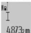
3a BKNIOUBAHe Ha Na3epa H3a N3MepBaHe HA TINCHETI NO BeHbX KpaTkoTpaH0 6yToHa 3a N3MepBaHe (2).
H3mpeHaTcToHocTceNOKa3BaBpea3a
PnMHOROKpaTHN H3MepBaHnHa NbIKNHa eNHO CneIpyro pe3yNTaHTe OT NocJeDHNte H3MepBaHnCe NOKa3BaT BpeoBete 3a H3MepBaHa cToHOCt (a).
N3mepBaHe Ha nnooi
3a N3MepBaHnHa HnIOu HaTNCHe T He KOKoKpTaHO 6yToHa (12),DOKaTO Ha DnCnner He Ce NOBn HnDnKaunrTa 3a N3-MepBaHe Ha nIOU
CneTOBa H3Mepete NocTeOBATeHNO WInpoUHaTa HbJxNHaTATAkA,KaKTo H3MepBATEbJxNHa.Ja3epHnTlbUOC-Taba BKNIOeH MeXyD IBETe H3MepBaHnI.
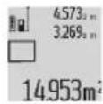
Cnep npknOuBaHe hA BTOPO Tn3MepBaHne nOuTa ce n3UcNBAaBtOMaTHo H Ce nOKa3Ba BpeDa 3a pe3yNTat (c).OTdJIHnTe n3-MepEn CToHOCTn Ce NOKa3BaT Ha peDObTe Cn3MepBaHn CToHOCTn (a).
H3mepeBaHe Ha 06eM
3a N3MepBaHnHa O6eMaHTNCHeTe HekONKOKpaTHo 6yToHa (12),IOkAto Ha DCNPEH He ce NOBn HNDkaTnTa 3a N3-MepBaHe Ha O6e
CneTOBa H3MepeTe NocIeIOBATEHNO IINPOUHHaTa, IbNHNHaTn BNCOUYHATA, KaKTo Ce H3MEpBATNbJKNHn. Na3epHnRT NbOCTABA BKNIQUEH MEXDy H3MEpBAHHTa.

Cne npknHbAHe Ha TpeTOTO n3MepBaHe 0eBt Ce n3UcNBA ABTomTuHO nCe no Ka3Ba B pea C pe3yIITa (c).OTdENHTe n3MepeHN cTOnHOCTn Ce NOKa3BaHa peoBeTe c n3MEpBAHn cToHOCTn (a).
CTOHOCHTHe HAD 999 999 m³ He MoRaT Da Ce nOKa3BaT, Ha DCINIeCe nOKa3Ba"ERROR". Pa3deneTe n3MepBaHnO6bEM Ha cactn, KOHTo moKeTe Da n3MepHTe NOOTdEHO n CNEt TOBA Da cb6peTe.
Henpebchato H3mepBaHe/MHHMaHHO/MaKcHMaHHO H3mepBaHe(BK.ΦHR.B)
PnHnpeKbCHaTO h3MeBaHe h3MePBateHHT ypeD MoKe da6bde npemecTBaH cnpraMo ueBbata TOka, KaTo h3MepeHaTcOnHOCT ce AkyanHspa BceKn 0,5 s. HanpImep MoKeTe Da Ce OTdaneUHTe OCTeHa Ha KeJahOTO pa3ctOAHne, TEkyuTo paoCToHnHe CE BxJa HnpeKbCHaTO.
3a HENpeKbChaTHn3MepBaHHHaTnCHeTe HeKoNkoKpTaHO 6yToHa 3a CMHa HpyHKuHa (4),DOKATO Ha DnCnIe Ce No- Bn HnDnKaUraTa L3a HENpeKbCHato n3MepBaHe. HATNCHe- Te 3a CTapTnPaHa HENpeKbCHato n3MepBaHe 6yToHa 3a n3MepBaHe (2).
PexmbT3aH3MepBaHe HA MNHMym CnyxHa onpeJnHe Ha Hau-Kbcoto pa3ctoHne OT onpeJenHa Touka do oBeKT. Toi MoKeJa Ce H3non3Ba Hanp. 3a onpeJenHTo Ha BepTNKann Hnn Xopn3OHTann.
PexmbT Ha 3MepBaHe Ha MaKCMMym CnyKn 3a onpeDenHa Ha Hau-ToJAMOTO pa3cToHHe OT onpeDenHa ToKa do oBeK. Toe none3eH Hanp. 3a onpeDenHTo Ha dHaorohnn.
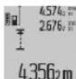
Bpea3a pe3yntata (c) ce noka3Ba aKtyanHa- Ta cTOnHOCT OT h3MEpBAHe. B peoBete 3a CTOnHOCTHa h3MEpBAhe (a) CE noka3BaT MaK- CHMaJIHATA ("max") H MINHMajHATA ("min")
CTOHCTHaH3MEpBaHe.Te3N CTOHOCn CE IpPOMeHAT,AKO TEKUYUo H3MepeHaTa eNo-MaJIka,peCn. NO-TOJMA CbOTBETHOOTDOCEAunHTe Ha-MaJIka Hau-TOJMA CTOHOCn
Upe3 HATNCKAHe Ha 6yToHa 3a H3TpNBaHe Ha NAMETTA (8)DO- ceraaHHTe MHHMaJIHN, peCn. MaKcHMAJIHN CTOHOCTN CE n3TPBbAT.
Upe3 HATNCKAHe Ha 6yToHa 3a H3MepBaHe (2) INpeKpaTBAte NOCTOHHOTo H3MepBaHe. IocneHATA H3MepeHa cTOHOCT ce NOKa3Ba B pega 3a pe3yntata (c). NOBTOPHO HATNCKAHe Ha 6yToHa 3a H3MepBaHe (2) CTAPnHa HENpeKbCHaT0I H3MepBaHe OTHBO.
HenpeKbCHaTOn H3MePbAHe Ce H3KJIIOuBa ABTOMaTHUHO CnE 5 min ABToMaTHUHO. NocneHATA H3MepeHa CTOHOCCT ce noka3Ba B pega 3a pezynata (c).
HnpeKTHo H3mepBaHe Ha pa3ToHHne
HINIpeKTHOTO H3MepBaHe Ha IbJxHa Cnyx 3a H3MepBaHe Ha pa3CTOHHa, KOHO He MOrAT da 6bDat H3MepEHHeNOCpeDCTBHeO, Tb KaTO NO TbTA Ha IbUa HA mPnEHTCTBHeHIN Tb KaTO B KpaHATA TOkA HMA OTPa3RBAua IOBbpxHOCT. To3H MeToD Ha H3MepBaHe MoKe Da 6Be npINOKeHcAMo BBB BepTKaJIHO HanpaBHeHne. BcKO OTKIOHeHcXOpH3ONTaHn HO HAnpaBHeHne BOIn Do yBEnuYabeHa rpeWKAta B H3MepBaHTo.
Mekdy OTeHnHe H3MePbAHnna3epnrt nbOcTaBa BKNIOueH.
Pa3nonarate C TpryHKuIN 3a INHnpeKTHO H3MePBAhe Ha pa3ctoHHe, KOHTo MoRat Da 6bDat npinaraHn B pa3nHn CHTyaCIN.
a) INHINPEKTHO H3MEpBaHe Ha BHCouHnA (Bx. fHr.C)
HaTNCHe HE KekKOKpAHO 6yToHA 3a CmHa Ha cyHKUHTA (4) DOKaTO HA DCnPJIe He CE NOKaKe HNDIKAuHrTa 3a HHINpeKTHO I3MePbAe Ha BnCOuHn
BHHMabaIte H3MepBaTeJIHHrYpeJdaeHaCbIaTa BnCOUHnHa,HaKoTToE OJHnHaTKepaHnTOuKaHa H3MEpBaHaTa BnCOUHnHa.CneTToBA3aBbPTeTe H3MEpBaTeJIHHrYpeJOKOIOOTPaBHAta paBHnHa H3MEpeTe pa3CToAHHeTO(1)No HAuHnHOKOHTO H3MEpBaTeDbJIKNHn.
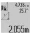
Cne npknIOVAhe Ha n3MepeBaHTo pe3yntaTbT 3a TbpcHTo pa3c0HHe "X" ce n3nncBaHa pena (c). N3MepeHHTe cToHocTH 3a pa3CTOAHHeTO "1" H bTbJa "q" ca H3nncAHn Ha peDobete (a).
6)ДБОИНΟΗΝΗΝΕΚΤΗΟ ΜΙΜΕρΒΑΗ ḌΑ ΒΗΚΟΥΝΗ (ВЖ.ФИг.D)
HaTHcHete HeKoJIKOkPaTHo 6yToHa 3a CmHa Ha cyHKuIHTa (4)doKaTO Ha dncnner He ce nokae HndkaunraTa 3a DBOHO HHdpeKTHO N3MePbaHe HA BCOUHnA
H3MepeteOTceuHTe"1"n"2"Ta3n NOcneObaTeHHOCT, KaKTO 06NHOBOEHO H3MepBaTe DblxHH.

CneI npKIOUOBAHe Ha H3MEpBaHTo pe3yNTaTbT 3a TbpcEHO tpa3cTOnHHe "X" ce H3NtCBHa pega (c). H3MEpeHnTe cToHocTH 3a OTCeYKIne "1", "2" H bTbJa "q" ce H3o6pa3raBAt Ha peoBete (a).
BHHMaBaIte npn BCnKNe EINHnHn H3MePbAHnHa HnHnpekTHOTOnnpedHe Ha BnCOuHnOtnpaBHata paBHnHa (Hnnp.3aHnrt Pb6 Na n3MepBaTeHNy ype) da octaba Hnnpomeheha.
B) HnHpeKTHo H3MePbaHe HaNbJXHa (Bx.ΦnT.E)
HaTNCHe THeKoNkoKpTaHO 6yToHa 3a CmHa Ha cyHKuHrTa (4) DOKaTO Ha DCnIeR He Ce NOKaKe HNdkAuaHrTa 3a HNDpekTHO H3MePbAe Ha DblnxHa
BnMabaiTe N3MePbATEENHITypeIaEHaCbuaTa BnCOUHa,HaKoTToE TbpcEHATA KpaHaTOUkaHaN3MePbaHETo.
CneToBa3aBbptTe H3MepBaTeHnHa ypeO OKoNo OTnpaHata paBHnHa H3MepeTe pa3ctoHneto "1" NO HaunHa, no KOIto H3MepBaTe DblxHH.
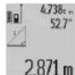
Cne npknKUcbHe Ha n3MepeBaHTo pe3ynTa TbT 3a TbpcHTo pa3cTOnHHe "X" ce n3nncBa Ha peda (c). H3mepeHInTe cToHocTH 3a pa3cTOnHHeTO "1" N bTbNa "d" ca n3nncAH Ha peoBete (a).
H3mepeBaHe Ha nnoou Ha cTeHN (Bx. f)
H3mepbaheTo Ha nlou HA CTeHN Cnyxn 3a onpeenHe Ha
06ua nloou, cyMa OT HAKOIO OTdEINHO H3mepeHH nloouni,
Hmaun O6ua BnCOUHa.
Ha nokaaHn npimep Tp86ba da 6bde onpeedeHa ooiata nloi Ha hKoKoCTeHN, KOHTo IMaTeH NcBua BnCOUHa HA NOMEeHHeTO A, HO Cpa3NJHbDJIKNH B.
3a N3MepBaHHa HnIOuHa CTeHa HAHTNCHe THeKoNkoKpTaH 6yToHa 3a CMHa Ha yHKuHTa (4),DOKato Ha nCnpe He ce IOBn INnKaUHTa 3a N3MepBaHe Ha nIOuHa CTeHa
H3mepete BncounHata Ha nomeeHHeTo A, KaKTo npn H3- MePBAHe Ha nbJnxHa. H3mepeHata cToHocT ("cst") ce noKa3Ba BV roPNr peC cb cToHOCHTte OT H3mePbaHe (a). Na3epbT OCTaBA BKJIOUeyH.
CneTOBaH3MpeTeBbIXnHaTaBHaNbPbTaCTeHa.IIIOuTaCeH3MepBaABTOMaTHNoHCnHO6p3AraBaHaPeDa3apeyIITa(c).Pioc-NeHATAH3MepeHaDbIXnHaEBCpeHNpaedcpeyIATOnH3MepBaHe(a).Pa3epbOCTa
Ba BkIIOueH.
Cera n3mepete dIbIKNHATA BHa bTOpata cTeHa. Ioka3BaHaTBA CpeINHpecBc cToHocT OTn3MepBaHeTO(a)CTOHOCTOTeHNHcHNO H3-MepBaHe ce cyMnpa cIbIKNHATA B.CymataHa DBeTe dIbIKHH("sum", NOKa3BaHa Ha don
Hnpe3a pe3yntaTn (a) ce yMHoxkBa cbc 3anaMeTeHaTa BncouHa A. Ooata nnoi ce n3nncBa Ha pe3a pe3yntaTa (c).
MoXeTe Da n3MepBaTe pOnH3BOEn H 6pO JOnbHnHTeHNn DblxHHn Bx, KOINTo ABTomAtuHO Ce do6aBrt N ce yMHOxA-BaT C BnCOUHHATA A.
IpeNoctBaKa 3a KopeKTHoTo onpeJeHHe Ha IIOUHTe e IpbBata NImepHa DblxHnA (B pa3rJedAHn PnIMep BnCOuHaA) Da e IeHTnHa 3a BCnKn YacTnHN NOBbpxHocTN.
H3mepBaHe HaHaKnOh (Bx. fhr.G)
HaTnchTe 6yToHa 3a H3MepBaHe Ha HAcNtOH (3) HA DnCn- nCe c NOKa3Ba HnDnKauHrTa 3a H3MepBaHe Ha HAcNtOH KaTO OTnpaBHa paBHnHa CnyxH 3aDnHa TcPaHa Ha H3MepBaTeHNH ype. Upe3 NOBtOpHO HATnCKaHe Ha 6yToHa 3a H3- MEPBaHe Ha HAcNtOH (3) CTpaHnHHTe NOBpXHocTH Ha H3- MEPBaTeHNH ype. Ce H3NOJ3BaT KATO OTnpaBHa paBHnHa n H3rIeNbT Ha DnCnIe. Ce NOKa3Ba 3aBbPTrH Ha 90^
HaHCHete 6yToHa 3a H3MepBaHe (2), 3a da fHKcapate CTOHOCHTA OT H3MEpBAHETO DA RA PnHEMeTE B nAMETTA 3a CTOHCTH. Upe3 NOBTOPOHO HAITCKAHe Bbpxy 6yToHa 3a H3-MepBaHe (2) H3MEpBAHToCe npOdbJxJaBa.
Ako IIO BpeMe Ha H3MepBaHTo DnCnIeT 3aOnue He da Mira, H3MepBaTeJIHHaT ypeE e 6Hn HAKNoHeH TBbpDe CnHO CTpaHnHNO.
AkoBOCHOBHTeHACTpOKnCTeBKIOUHNnФyHKUNTA"INITaIIHaIbEena",CTOHOCTTaHaHAKIOH CeNOKa3Ba H BpyrHTeΦyHKuNN3aH3MePbAHeBpei(d)HaHcNpner(1).
Функцин На Таймера
ФункцитаHa taImepa nomara Hapr. KOrato DBHKeHHa Ha n3MepBaTeHnY ypei ca 3aTpUdHeH NO BpeMe Ha n3MepBaHeto.
3aФyHKUHTaHaTaimepa3aPbXTeHaTHCNAT6yTOHa(6) DOKATO HaHNCINNEH Ce NOKAKe HNDAKUHTa
BpeBa CbC CTOnHocTn Ha n3MePbaHeTo (a) ce nokaaB BpeMeBnT nHTepBaJOT aKTNBpaHeTO Do n3MePbaHeTo. BpeMeBnT nHTepBaJMOKe Da Ce HAcTpOBA qpe3 HaTHcKaHe Ha 6yToHa cPiHoc (11) pecn. 6yToHa cMHyc (5) MeKdy 1 s H 60s.
24120m
Cnei n3TuHaHe Ha HactpoeHn HHTepBaI n3-MepBaHeTo Ce N3BbPbA aBTOMaTHuHO.ФyHKUrTa Ha TaIMePa MoKe Da ce I3No3BaI pNn n3MepBaHHa Pa3CToHnE B pAMKITE
HaDpyHnФyHKuHn3aH3MepBaHe (Hapn.H3MepBaHnloo).Cb6npaHn H3BaJdaHnHa pe3yntaOn OT H3MepBaHn, KaKTo N BkIOUbaHo HpeKm HENpeKbCHaTO H3MepBaHe He Ca Bb3MOxHn.
CnHcbk Ha nocJeHnTe H3MepeHn cToHOCTH
H3mepBaTeHNHYpeI3aIaMeTBA NocJeHNTe 20 H3mepeHn CTOHCTN H3uNCHeHTE C TAX BEINuHH N I NOKa3BA B O6paTHA NOCeIOBATEHOCHT (HaH-NaPeD NocJeHNO H3mepeHata CTOHCT).
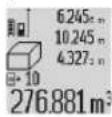
HaHCHETe 3a H3BKNBaHe Ha 3aanaMeTeHIne H3-MepBaHH6yToHa (7).HaIINcIIe ne Ce noka3Bape3yNTaO T NocEiHDto H3MepBaHe,3aeHOC INHnKaTOpa 3a CnCbKa Cbc CTOnHOHnH3MepBaHe (e) H C MCTOTOB NaMeTTa 3a HO
H3tpnBaHe Ha H3MepeHcTOnHocTH
Upe3 KpaTkoTpaHbHaNTCKaHe Ha 6yToHa (8) npH BCnKpexmHa H3MePbaHe MoXeTe Da H3TpneTe NocJeHO H3MepeHaTa eHNuHcHc ToHocT. Upe3 MHOrOKpaTHo KpaTKoPaHbHO HATNCKaHe Ha 6yToHa Ce H3TpBaT eHNuHcH H3MepeHH CToHocTH B O6paTHa NocNeObATEHoCT.
3a da ce n3Tpne aKtyaHNO NOKa3BaHOTo BnHcBaHe CnncbKa Cbc CTOnHOCTn Ha n3MepBaHe, HATNCHEte 3a KpaTko 6yToHa (8). 3a da n3Tpne Te cNna CnncbK cbc CTOnHOCTn Ha n3MepBaHe H KOHCTaHTaTa "CST", 3aDpBxTe HaTHcHAT 6yToHa 3a CnncbK Cbc CTOnHOCTn Ha n3MepBaHe (7) H eDHOBpeMeHHO HATNCHEte 3a KpaTko 6yToHa (8).
BbYHKnIaTa 3a H3MepBaHe Ha IIOUHa CTENH pINpNbPBO TO KpaTKoTpaHbHaTcKaHe Ha6yToHa (8) Ce H3TpNbA NOeHATA eHNHua CTOHOCHT Ha H3MepBaHe, pIN BTOPOTo HAtCKaHe CE H3TpNBa BCuKNbX, a pIN TpeTOTO HAtCKaHe CE H3TpNBa BnCOUHaTa Ha NOMEueHHeTo A.
Cb6npaHe Ha H3MepeHn CToHOCTH
3a da ce do6abT CTIOHOCTH Ha N3MepBaHe, NbPBO H3BbPwTe PpO3BOIHO N3MepBaHe nn N36peTe BnncBaHe OT CnCbKa CbC CTIOHOCTH Ha N3MepBaHe. Cne ToBa HAITcHe 6byToHa IIIOc (11). Ha DnCIne Ce noka3Ba 3a NotBpbKDaBaHe "+" Cne ToBA N3BbPwTe BTopo N3MepBaHe nn N36peTe dpyra CTIOHOC TOT CnCbKa Cn3MepEn CTOHocTH.
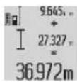
HaHNCHE 3a H3BnKBaHe Ha Cymata OT DBeTe H3MepBaHHa 6yToHa 3a pe3yNTat (6).H3uNCHeHNEtO Ce NOKa3Ba B peDobete CbC CTOnHOCTNa H3MepBaHe (a), Cymata e B peda 3a pe3ynTat (c).
CneH34NCBAHETO HA cyMaT KbM TOHpe3yTTaMOKe da ce doBaBt OOE CTOHOCHT HA H3MEpBAHe, BnHCBAHH B CnncbKa CbCTOHNOCHT Ha H3MePBAHe, AKO NpeDN H3MEpBAHETo CbOTBEHO CE HAtNCHE 6yTOHa NIOc (11). Cb6npaHETO ce npeKpaTBA Upe3 HAtNCKAHe Ha 6yTOHa 3a pe3yTTaT (6). YkaaAHNA 3a cb6npaHe:
He b3MOxHcMceHoTo cb6HpAe Ha dbJKNHH, nIOu HOBm. Ako Hanp. Ce doBaRT cTOnHOCT 3a dbJKNHa H 3a IIIOU, npn HATNCKaHe Ha 6yTOHa 3a pe3yNTat (6) 3a KpaTKo Ha DCNPNCe pOKa3Ba "ERROR". CneI ToBa H3-MepBaTeHNHt ypeD CE Bpbua B NocJeHNO H3No13BaHaTa FyHKUH 3a H3MepBaHe.
-06aBcpe3yntataOeHNO3MepBaHe(HaNP.CTOHCTHaOBem),PnIOCToHNNH3MepBaHHcEO6aBBNOKa3BaHATA Bpeda3pe3yNTAT (c) CTOHOCT Ha3MepBaHe.106aBHeTo HA CTOHOCTHOTeHNHUNH3MepBaHHoTpeoBBeCbC CTOHOCTHHa H3MepBaHe(a) He e BB3MOXHO.
I3BaXdAHe Ha pe3yIaTH OT H3MepBaHTo
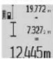
3a n3BaXdAHe Ha cToHocTn Ha n3MepBaHe HATCHETe 6yToHa MNHyc (5), Ha dncnpe Ce noKa3Ba 3a NotBbpxJaBaHe "-". HaunbT ha pa6oTa e ananoruyen Ha "DobabHe Ha cToHocTH OT n3MepBaHe".
Yka3aHna 3a pa60Ta
06xnyka3aHHN
IIO Bpeme Ha H3MepBaHe npHemaAaTa nea (17) nOTBOpBT 3a N3XoJnna naepeHbU (16) He Tpr6Ba Da bDat zakpnBaHH.
No Bpeme Ha 3MepBaHe 3MepBateHHT ypeH He Tpa6Ba Da 6bDe pmeCtBAH (C 3KIOUeHne IpnpeXHM Ha pa60a HnpeKbCHATO 3MepBaHe). 3aTOBa NO BB3MOxHOCT DOINPAIte 3MepBaTeHNHrypeD IO 3dPABA ONOPHa NOBbpHXOCT.
ΦaKTopH, BnHnEeHNBbPxy DnHaNa30Ha Ha N3MepBaHe
Hana30HbT Ha H3MepBaHe 3aBnCt OT CBeTNIHHte YcNOBnI HOTpa3HTeHATA CnOC6HOCT Ha NOBpXHOCTTA,do KOrTO CE Mepn.3aNo-DO6pa BHNMOCT Ha Na3ePHNIA IbY npn pa6Ota HA OKPHTO INPN CHINCA StbHueBa CBETNHa H3NOL3BAITE CNEuaHHTe OUYIIA (28) (HE Ca BKIOUeHN B OKOMNKeTBOKATA) AND P3RABaMa MEPNTENHa IIOUka (29) (He E BKIOUeHa BOKOMNKeTBOKATA), HIN 3aceHETe NOBpXHOCTTA,do KOrTO H3MEpBaTe.
ΦaKTOpH, BnHReuN BbPxy ToHocTtHa H3MepBaHeTo
Bb3 OCHOBa HA non3BaHIne npn H3MepBaHTo FO3Nueckn efeKTH He MoRat Da 6bDat N3KIOUeHN B3HKnBAuIN rpeJIKn npn H3MepBaHTo Do pa3NIuHn NOBbPxHOCTn. B TOA YNCLO BIN3AT:
- np03paunnoBbpxHocTHn(Hanp. cTBkNo, BOda),
-OTpa3raBaunIOBbpxHOCTn(HaNP.nonnpaHHMeTaHIN npedmTH,CTbKNo),
-IOpeCTN NOBbpxHOCTH(HaNP.ⅢOlaunHHMaTePnaJIH)
- noBbpxHocn C rpanaba CTpykTypa (Hanp. rpy6a MaHnKa, eCTECTBeH KaMbK).
PnHHeo6xOmoCT npn H3MepeBaHe Do TaKbNA NOBbPxHOCTn H3NON3BaTe Otpa3Ba7a MePeTEnHa PIOUka (29) (He e BKNIOUeHA BOKOMNNEKTOBkTa).
OcbEN TOBa rpeHn NOKa3AHn MoRat da ce nOyUaT npn H3-MepBaHe Do NOBbpxHOCTN, KOINTo Ca nOJ bFbl.
ToHocTa Ha H3MepeHaTa CToHOCrMOKe Da Ce NOBnHe CBtO Taka OT HaHnUeTeo HA Bb3DyWnCNoEBe CbCnIeH rpaIHeNT Ha TempePaTAtu NnNHNpEeKTHOpaXeHHa.
PpOBepKa Ha ToUHocTHa KAnH6pHpaHe Ha H3MepBaHTo HA HAKIOH (Bx.ΦnR.H)
IpoBepBaIte nepHOJNUHO TOUHcTtHa H3MepBaHeTo Ha HAKIOHN. TOba Ce H3BbPbWA ype3 H3MepBaHe CbC 3aBbPtAHe. 3a CENTa NocTaBeTe H3MepBaTeHnHa ypeIerHa HA MaCa H3MepeTe HAKIOHa. 3aBbPTe H3MepBaTeHnHa ypeI Ha 180^ H3MepTe HAKIOHa OTHOBo. Pa3Nkata Ha H3MepEHnTE CTOnHOCTn TpR6Ba Da e Hain-MHOrO 0,3^
Pnno-ToIeMHOTKIOHHeHHrTp6BaJa KaIINbPnpate N3MepeBATEHNHpyep NOBTOPH.DpbXTe 3a ceNTa 6yToHa 3a H3
MepBaHe C HAKnOH (3) HATnCHaT. CneBaNTe yKa3aHnraHa DnCnIe.
IpoBepKa Ha TOUHOCCTTHa H3MepBaHETo Ha pa3CTOHHne
Moxete da npobepnte ToHocTt ha n3mepBaTeHHn ype, KaKTo e ONcaHO NO-DOy:
-36epete HnnpomeHaa ce oceka cNbJnHa MeKdy 1 n 10 m, uHTO TOHa dJbJNHa Bn e h3BcTHa (hAp. uHPOunHa HA CTAR, OTBOP HA BPATA T.H.). N3mepBaHOTo pa3ctoHHe Tp6Ba Da e B3akPHTO NOMeUHe, UeNEBaTa NOBbpxHOCT Ha N3MepBAHeto Da e rnaKa n OTPa3raBa-ua do6pe.
- H3mepete otceukata 10 nbtn nocneboTeNo.
OTKNOHeHHeTo Ha eINHHnHHe N3MepBaHnO t CpeHaTa CTOnHOCT He Tp8Ba Da HaNBIuBaT ±2 mm. 3aNNuTe pe-3yNTaHTe O T N3MePBAHeTo B InpTOKoI, 3a Da MoKeTe Da HAnpaBHe TcPbHeHHe Ha ToHOCTa B No-KbcEH MOMENT.
Pa60Ta c6c cTaNb (pHnHaIeXHoCT)
H3non3BaHTo Ha cTaTHB e Heo6xOJIMO CneuaJHO npn H3- MePBAHe Ha rONEM pa3CTOHHa. KaTO h3NON3BaTe OTBopa c pe36a (27) 3axBaHete ypeDa c 1/4" pe36a KbM nIOOKata 3a 6b5p30 3axBaJaaHe Ha cTaTHBa (19) INN oBHKOBHe CTATNB 3a fOtoanapatn. 3aTeHHe To C BnHTa 3aactOnopraBe Ha nIOUkata 3a 6b5p30 3axBaJaaHe Ha cTaTHBa.
IocTaBete CbOtBeTHO OTnpaBHATA paBHnHa 3a H3mepBaHe CbCTaTHB Upe3 HaTnCKaHE Ha 6yToHa (10) (OTnpaBHpaBHHa pe360BNOTBOP).
Pa60Ta c 3MepBateHa WHa (Bx. fHr. I-K)
N3MepBaTeHnHaTa 25) MoKe Da ce H3No13Ba 3a No-To-ueh pe3yIaT ot N3MepBaHe Ha KaHIO. N3MepBaHNrTa Ha OTdaJeueHOCT He Ca Bb3MOxHH C N3MepBaTeHnHaTa WnHa.
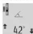
IocTabete H3MepBaTeHnHa ypeK KaTo e Noka3aHO B H3MepBaTeHnHaTa 5HHa (25) nro 3akJIOUcTe C NoCTa 3a 3akJIOUbaHe (26).HaTNCHeTe bYtoHa 3a H3MepBaHe (2), 3a da AKTHBnPatepeXIMHa Ha paBota "H3MepBaTeHnHa"
PpOBepBaItepeIOBHO TOHOCTaHa H3MepBaHToC hAknOH Upe3 O6paTHO H3MepaHe IINUpe3 IIN6eJIte Bbpxy H3-MepBaTeNHaTa 1nHa.
PnnoTOnEMNOTKNOHEHNA Tp6BaJa KaJIb6pnpate N3MepBATEJIHHypeN NOBTOPO.H.PbXTe 3a CEENTa 6yTOHa 3a H3-MepBaHe C HAKNOH (3) HATNCchat. CneBaTe yka3AHnTa HaDcnnE.
3a npekpTaBaHa Ha pa6oTHnpeXm "N3MepBaTeHnHa 1Ha" N3KIOUeTe N3MepBaTeHnYpeN ITO N3BaTeOT N3-MepBaTeHnHaTt HnHa.
TpeuKN -Pnunnn 3a Bb3HHKBaHe HauHH 3a OTCTpaHBAhe
PnunHa Nmou
PepypeHnTENHnT CmBON 3a TemnepaTypa (j) Mnra, He e Bb3MOXHO N3BbPwBaHTo Hn3MePBAHH
I3MepBaTeHnHrTypee H3I3yakaHTe,IOkato TempeaBbH DOnyCTHMn TEMepaTy-TypaHa I3MepBaTeHnHpeH nnana3OH 3a pa6Ota OT-
PpnuHnA Nmou
10°C +50°C (B pexnHa ypeiDocTnHe DOnyCTmHn HnpeKbChato n3MepBaHe pa6oTeH dHaanaoH. 10+40C).
HndkaTop"ERROR"Ha dnncnne
Onnt 3a Cb6bpaHe/N3BaxKaJa-Cb6bpaTe/N3BaxKaJaTe ca- He Ha cToHIOCTn Cp3JIuHn MO CToHIOCTn eEHaKBA pa3-MepHN eINHHn MEPHOCT
bBbT MeKdy Na3epHnIbUyBENuHTe bBbTa MeKdy naN cEneBaTaNOBpXHOCTe 3epHnIbUy NcEneBaTaNTOBpDEOCbP. BbPxHOCT
LcneBata NOBbpxHOCT Otpa- H3nON3BaIte OTPaxATEHATA 3raBA TBbpDE CINHO (HaNP. nnoUka (29) (DOnbHHTENHO orneJano),pecn.TbbpDe npncnoc6neHHe) cnafo (HaNP, yepen nnat)
MNI OKJHaTc Tbpe CnHa.
H3xoJaTtOBp3aNa3ep- H36bpuTeH3xoJaTnO-TN HnB (16) pcn. npema-Bop 3a Na3epnHa Lb4 (16) uata nea (17) ca 3anoteH npema aata nea (Hap. B peaynta Ha praKa (17) c Meka Kbpna Tempepatpynpomha).
I3yHcneHa cTOnHocTe no- Pa3deneTe H3yHcneHMeTo Ha roJMa oT 999 999 m/m²/ otJeHHn CTbIKn m³.
HnDnKaun,>60oHnn<-60oH nDnCnne
HaXbPnE eDnana30Ha 3a N3nbHete N3mepBaHeto B
N3MepBaHe Ha HAKIOH 3a paMKITE Ha CneuΦnUpa-
TeKyuaTc yHKn,peCn. HnA Dnana30Ha HAKIOH.
npemHaTa e OtnpABHata
pabHHa.
HnDnKaaun "CAL" HnDnKaun "ERROR" Ha nCnIeR
KaHbPnPaHeTo Ha H3MepBa- H3BbPte KaHbPnpaHe OHTeHOHa HAKIOHN He e N3Bbp- HOBO CbIpaCHO yka3aHnTa 1eHO B npaBnHaTnOncne- Na DCnner n no pOceDpyaDOBaTeHnOCT HnB npaBn- Ta, ONCaHa B pbKOBoCTBOHnTe No3uN. TO 3a EKcPiOaTaUHA.
I3non3BaHnTe 3a KaHbpi- NaTOpe TaHbnpaHTo NOBbpxHOCTn He ca Ha XOpH3OHTaHa,peCn.Bep6nIcTPOrO XOpH3OHTaHN HkALHa NOBbpxHOCT; npn HcTOPOBtHKaHn. Heo6XoDMOC TpOBepe TNOBbPxHOCTne C BODHa IIN6ena.
IpiHaTnCKaHe Ha 6yToHa NOBtOpTe KaHbPnpaHTo H3MepBaTeHNHTypee e 6Hn DpbXte H3MepBaTeHNHn npEmecTeH,peCn.HaKnHOHe. yPeH HeNoBnKHO No BpeMe HaHaTnCKaHe Ha 6yToHa.
HndkaTOp 3a akymyNatopHaTa 6aTepeHg (g), npedynpeXdHeHne 3a TemnepaTypa (j) HnDnKaun "ERROR" Ha dncnnen
TemnepaypataHaH3MepBa- H3yakaIte,doKaTo TemnepaTeHNrT ypeE n3BbH dOync-Typata DoCTNRHe DOnyctTMNTHMN DaNa3OH 3a 3apeJaHe Ha akymnatophata 6atepna.
PpNnHa NmOu
Haakymyntopnata6aTepn
HndkaTop 3a akymnaTophata 6atepna (g) HndkaTop "ERROR" Ha dnncnne
HanpekeHneto 3a 3apeKdaHe Ha akymlyaTophata 6aTePnHa He e npabnHo
YBepete ce,ue e 3apndHoto yCTPOBCTBOE BKNIOHO npaBnHO B KOHTaTaN daNN MmKpO USB Ka6bIb T cyHKUOnHpaN3PAnHO.AKO CmBoJbT Mra, aKymNaTOphata 6aTePNe NOpeDeHa TpaBa Da 6bJe 3aMeHeNA B OToPn3npaH cepBn3 3a enekTPOHCTpyMeHTn Ha Bosch.
Hndkatop 3a akymynatopnata 6atepna (g) n cHMBon C yacobnK (f) na dncnnne
3HaHTeHNO yDbNKeHO BpeMe 3a 3apeKdaHe, Tb KaTo 3apAHHT TOk e MaNbK.
H3no3BaTe cmo opnHaHHMaMKpo USB ka6en Ha Bosch.
Pe3yIaTbT OHTN3MepBaHeto e HeoctOBepen
Lenebata NOBpbxHOCT He Otpa3BaNo NOJXODJIH NaHH3a EHN3NaHNO3MEpBAHe (HaNP. BOJNA NOBpbxHOCT, CTbKIO).
PokpnTe ceIeBaTnOBbpx-HoCT
HxOaIyIaTOTBOp3aNa3ep HnIbU(16)peCn. npHeMa- taNeua(17)caNOKpTN.
Ocbo6oTeH3XoJyIuOTBop3aNa3epnHa1bU(16)pecn. npHeMaIata neua(17)
N36paHa e rpeuHa oTnpaBHa paBHHa
N36epTe OTnpaBHa paBnHa, NOxOJa 3a N3BbPbBaHOTnMepBaHe
IpenaTCTBne NO nTbHa na-3epnna
LaIata IaIeepHa ToKa TpA6Ba Ia IaIaIHe Ha NOBbpxHOCCTa,IO KOrTO Ce H3MepBa.
HnHKaunraOCTaBa HnpeMeHa HnN H3MepBaTeHHNHTypepearnpa HeoayKaBAHO HaHaTHcKaHe Ha6ytoH
CoΦTyepHa rpeIka HaTnCHeTe eHNOBpeMeHHO
6yToHa 3MepBaHe (2) H 6yToHa 3a H3TpBaHe Ha NaMeTa / NcKOBnI PpeKbCba(8), 3a Da Hynipate coPtyepa.
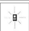
N3mepBaTeHHnT ypeI cneI 3a npabHnHOTO cnФyHKUHOHPaIe npn BCAKO N3MepBaHe. Ako6bde yCTaHOBeHa NOBpeIa,Ha DcNnerce H3o6pa3raBa cmo NOKa3AHIN BCTPAHN CmBON.BtakBcnyau,KAKTO nA KO NOCOueHIne
no-rope MepKn He IOBeDaT Oo OTcPaHbAe Ha Bb3HNKHaI I np6Iem, npdaTe N3MepBaTeHnIype3a pEmOHT BOTOpH3npaH cepBn3 3a enEKeTpOnHCTpyMeHTn Ha Bosch.
PoaBpKaHe n cepBn3
IopdbpxaHe n nouHCTBaHe
CbxpaaBaIte n npehacnIte ypeIa cmo BbB BkHoueHaTBA OKOMNKeTobKaTa npedna3Ha YaHTa.
IopdbpxkaTe N3MePbaTeHnHa ypeD BnHaN uCT.
He notonraBte n3MepBaTeHHypeD BbB BOa nn npyn TeuHOCTH.
N36bpcBaiTe 3aMbpcBaHnTc MeKa,NeKo HbNaXHeHa Kbpna. He n3noi3BaIte NouchTbaun npenapn nn pa3T BOpnteni.
OTHACnTe Ce CneuHaHO KbM PnpMaaTaJeua (17) CbC CbTOBHNMaHHe, C KOeTO Ce OTHacrte KbM OUnna HnO6eKTHBaΦoToaNapat.
PnHne06xOIMOCT OT pEmoHT npeOCTABNte H3mepBatenHHypeD B yHaTata (24).
KnentcKa cnxk6a H KOHCyntaun OTHoCHOynotpe6ata
CepBn3bT ue OTROBOpHa Bbnpocite Bn OTHOCHOpeMOHTn I noDpBkKa Ha 3aKyupeHnO T Bac npOyKT, KaKTo n OTHOCHo pe3epBHNuactn. POKOMnoHEHTN Ueptexn HnHΦopMa- qna 3a pe3epBHNte qactn ue OKPneTe n Ha: www.bosch- pt.com
EknbT NO KOHCyNTaIGN OTHOCO yNtpe6aTa HA Bosch ue Bn NOMORHe C yIOBOJCTBHe npn BbNpocn 3a HauHTe npoDyKTHn TExHNte akcecoapn.
MOnn, npBnpoCn n npn npOpBuBaHe ha pe3epBn qactn BnHaH noocuBaTe 10-uaPpeHn KaTaoXeH Homep, n3nncaH Ha Tabekata Ha ypea.
Блгария
Robert Bosch SRL
Service sculelectric
Strada Horia Macelariu Nr. 30-34, sector 1
013937 Bucuresti, Romania
Te.n.: +359(0)700 13667 (bblraptckn)
_aKc: + 40212331313
Email: BoschServiceCenterBG@ro.bosch.com
www.bosch-pt.com/bg/bg/
TpaHcnpOpTuPAne
BkIIOUeHInTe BOKOMIIeKTOBkATA IINTHeBO-IOHHN aKMyIyTAPoHN 6aTePNi Ca B O6XBata Ha N3NCBAHnra HA HOPMaTHBHnTE DOKyMeHTn, KAcaeu npOdyKTc C NOBmHea OAnCHOCT. AkymyIaNtOpHInTe 6aTePNi Moat Da 6bDat TpaHCnOpTHpaHHOT Notpe6HTenHa Iy6HnHm MeCTa 6eDOnbHInTeHHpA3peHInTeHH.
PnTpaHcnpTnpaHeOTpTeHCTpaHH(Hanp.npiBb3dyweh TpaHCnoptnnINONL3BaHeHaKypnepcNycny)mAmCneuAIIHN N3NCBAHNRkM ONAKOBaHEO6O3NaabaHEToM.
3a ceta npn noTROBkata Ha naKeTnpaHTo Ce KOHCyTTpaIte Ceknept B cbOTBeTHata 0bnaCT.
Бракуван

C orne ona3BaHe Ha OKoHnHa TcpeHa n3MepeBaTeHNHTe ypeNi, 3apdHnTe yctpoiCTBa, akymyna
TopHnTe 6aTepHH, dONbHNHTeHHte npncnoCoB-He H nOaNKOKBnTe Tp8Ba Da 6bDat npedeAeHH 3a OOnl3oTBopBAHe Ha cbDbpxaHTe Ce B TEx CypOBHH.
He n3XbBpIaIte h3MepeBaTeHnHTe ypeI, 3apIHNthe yCTpoIcTBA n akymyIaOpHnTE 6aTePN np6bTOBtE OTnabu!
Cama 3a ctpaHn ot EC:
CbINaCHO eBpOeNcKa dIpeKTHBa 2012/19/EC n3MepBaTeHNHTypeHn 3apAHN yCTpoiCTBa, KOIO He MOrAT da Ce non3BaT NOBEue, a CbINaCHO eBpOeNcKa dIpeKTHBa 2006/66/EO NOBpeEHn Hn N3xA6BeHn O6NKHOeHn Hn akymnatopHn 6aTeepn TpR6Ba Da ce cb6npat n IpeDaba 3a ONON3OTBOPBAHe Na CbIbPkaUInCe CB TIX CypOBHN.
Akymynatopn6atepn/6atepn:
JIHTHEBO-NOHHN:
Moi, cna3BaIte yka3aHnraTb pa3eJa TpaHcnpTnpaHe (Bx. ,TpaHcnpTnpaHe", CtpaHnca 238).
Donycka ce demoHTnpaHTo Ha BrpaJeHrTe akymyataTopn6aTePNcMoOT KBaHbHnHpHaNTEXHnC 1e npHpOoc6bpa3hOto Hm HxBbPnHe. Pn OTBa-paHe Ha Kopnyca Ha H3MepBaTeHNH ypeD ypeDbT MoKe da 6bde NOBpeH.
3a da n3BaDnTe akymyNatOpHata 6aTepeRr O n3MePbAeHnHn HnCTpyMeHT, BKNIOUte N3MePbAeHnHn HnCTpyMeHT, DOKaTO akymyNatOpHata 6aTepeRr 6bJe pa3peDeHa HanbIHO. PaBnTE BnHTOBeTe Ha Kopnyca H ro OTBopeTe. 3a da npedeOTBpaTnte KbCO CbeHNHeNe, n3BaJdaTe KJIemTe Ha akymyNatOpHata 6aTepeRr noCleNoBcTeHNO eHa No eHa N3OJIpaTne NOnIOcTe. Dopn H npn PbIHo pa3peXdAne B akymyNatOpHata 6aTepeRr OCTaBA OrpAHueHo KOINueCTBO OCTaTBuen 3apRd, KOITc Ce OCBOOxJaBA npn KbCO CbeHNHeNe.
MaKeDoHcKn
Be36eHocnHaNoMeHH


CnTe yNaTCTBa Tpe6a Da ce npOHTaaT Na Da Ce BHIMaBA Ha HNB,3a Da MoKe
6e36eHno 6e3 onachoct Da pa6oHTne co MePHNOT
yepe.Дokonky MEPHOType He ce KOpNtCH cornacho npnoKHeHTe HnCTpyKUnn, MoKe da Ce Hapuwn fYHKJata Ha BrpaDeHNTe 3aWTHTN MExaHN3MBO MEPHOType.He rOwTeTyBaJTe ppeDyPepyBauchte 3Haun. IO6PO 4yBAJTE rOBNE yIATCTBA IN PPEDAETE r3AEHO COMEPHNOTYPEI.
BHHMaHHe -DOKKky KOpHCTNe Dpyr Hyei 3a noDecyBaBe HpaKyBaBe OCBeH OBDe HabeJeHNTe Hnn NONHAKNIOCTaIKN, OBA MOKe Da DOBeE Do ONaCHA N3NOKeHOCT Ha 3pauehe.
MepHnotypece hcnopayBa co npepynpyBaqu3nak (o3naheHO ha npka30Ha MePpHnotypeHa rpaqNkata cTpHa co 6poj (20)).
Dokonky TeKcTHa HaneHHaTa 3a npedypeyBaHe He Ha BawHot ja3NK, Bp3 Hero 3aneneJa HaneHHaTa Ha BawHot ja3NK nped npBata ynoTp6a.

He ro hacouybajte nacepcknot 3pak kon Hnua nn XNBOTHn HEmoJte H Bne camnte da rnaTe BO dHpeKTHNOTnn peektnpaKnot nacepckn 3pak. Taka
MOKe Da rH 3acnEnIte NuaTa, da npedn3BnKaTe HecpeKn nn Da rH OWTeNTe OUYte.
Dokonky nacepckhot 3paK Docnee do ouHTe, Behdau Tpe6a da th 3aTbOpHe I da ja TprHete rnaBata od nacepckhot 3paK.
He npaBeTe npoMeHH Ha nacepcknOTypeI.
He rH KopHCTe Iacepcknte 3aHTTHN OUYn KaKo 3aHTTHN OUYn. Iacepcknte 3aHTTHN OUYn cIyKaT 3a noIO6po pacno3HaBaHe Ha Iacepcknot 3paK; cenak, THe He wHTTaO IacepckTO 3paueHe.
He rKOpHCTeIacepckNTe3aHTTHN OuHa KaO OuaHa 3a COHcE Hn Nk BO COo6paKaJOT. IacepckNTe 3aHTTHN OuyHa He DaBaat cenocha UV-3aHTTa n Ro HAmaIyBaat npeno3HaabaBeto Ha 60n.
MepHnot ypeI cmEe da ce nonpaba caMo oI cTpaHa Ha KBaIIHΦNkYBaH CTpyeH NepcoHAn Cama co OPHTHAHn pe3epBHN DeIOBn. CaMo HA ToJ haun HKe 6NDte CNrpyHb BO 6e3eHocTa Ha MEPHnot ypeI.
He rnoctabajte deuata da ro Kopnctat nacepcknot mepeh ypei 6e3 ha3op. Be3 hao3op, Tne moke da 3aclenat npynnna.
He pa6oTe co MepHnot ypeB OOKOnnHa Kaede nocToH onaChOCT oEKCnNo3nJa, KaDe HMa 3anaHbN TeHOCTH, rac HnI npaunHa. MepHnot ypeD co3DaBa HCKPN, KOJ MOKe Ja ja 3anaat npaBt HnI napeata.

3aHTTe Ro MepHOT ypeo od TonnHa, Ha np. HcTo TaKa Ond NoctoJaHa N3IOXeHocT Ha COHcEBN 3paun,Orah,BODA HIN BnaxHOCT.
Iocton onacnoct Oekcnnoja.
He ro Kopnctete MeHHoTypeCo BMethat Micro-USB ka6en.
Be36eHochn HanomeHn 3a noHaun
Oboj noHaH He e npedBnDeH 3a ynoTpe6a od deua n Iuca co orpaHnueHn cH3nK, ceH3OpHn Hm MeHTaHH CnOC6HOCTN Hn CO HeIOBOHNO NCKYCTBO n 3HaEbe. Oboj noHaH moKe da ro KopHcTaT deua na 8 rOHN Kako n Iuca co orpaHnueHn cH3nK, ceH3OpHn MeHTaHH CnOC6HOCTN Hn CO HeIOBOHNO NCKYCTBO n 3HaEbe, DOkONky ce noJ Ha3Op od Iuca ODROBOPHn 3a HNBATA 6e36eHocT nn Ce noDyueHH 3a 6e36eHNo paKyBaHe co NoINaOT n rna Pa36nPaat onachOCTnte KOH MoKe Da npoN3ne3a TnpaHI Toa. NaKy noctOn onaCHOCT oI porpeHa ynoTpe6a n NobpeDi.
3a BpeMe Ha KopnCTeIbeTo, UnCTeIbeTo N ODPxYBaIbeTo HndrNeyBajTe rN deuata. Taka Ke ce OCHypaTe DeKa DeuTa HeMa da cn nrrpaat Co nonHaOT.
IpxeTe ro nonHauOT noJaneky oddoxndnnn Bnara.HaBneryBaBeTo Ha BOda Bo enektpnHnot ypeIro 3rOlenMyBa pN3NKOT oEneKTPnueH ydp.
HanoHete ro mepHHOT ypeD co hcnopauaHHT nonHa.
OpjxBaJte ja nCTOTATA HA nonHaoy.10KoKy ce H3BaIka, noCTOn OAnCHOCT OeNEKTPuHy yap.
Ppe cekoe KopncTeHe, npOBepe rH nonHaoyot, Ka6enOT n npKnyOoKOT. He ro Kopncte TnonHaoyot, DOKONky 3a6eneKeT OWTetyBaHa. He ro OTbopajte camn nonHaoyot H octaBeTe Ro HA nonpaBA KaJ KBaHnФkUyBaH CTpyuH NepcoHAn Koj Ke KopnCTn Camo opHnHaAHN pe3epBHN DeNoBN. OHTeHnOT nonHaay, Ka6en n npKnyOoR 3rOleMyBa Pn3HKOT 3a eNEKTpuH yap.
He ro KopHCTe TnHaOH Ha neCHO 3anaHbna noDnora (Ha np. xaptnja, TeKCTn HTH.) OGH. BO 3anaHbA OKoHnHa. NoCTOn OnaCHOt od nokap 3apaHn
3aToIyBaHbTo Ha ypeoT UTo Ipon3nErYBa npH nONHeBcTo.
Dokonky ce ouTetn 6atepnjata Hn He ce Kopncn npabnHIO, OJ Hea MoKe Da n3ne3 neapea. BheceTe CBK BOzIyx I DOkONky HMa NOBpeHn OOnHeceTe rHa nekap. Papeata MOKe da rHn Haupa3HN dUnHHTe naTuTa.
Onnc Ha npoH3B0DoT n nepOpMaHCnTe
Hameheta ynoTpe6a
MepHHOTypee hameHET3a MpeHe Ha daJeHHN, DOnKHHN, BnCHH, pAcTojaHHJa, KocHH N 3a nPecMeTyBaHe HAnOBpHHN INBOLyMeHN.
MepHnoTypee noroedn 3a KopHeBe BO BHaTepeuHn HADBOpEeH npocToP.
Hnyctpaunja ha KOMnOHeHTN
HymepnpaheTo Ha cInKHe Co KOMNoHeHTn Ce OndecyBaHa npka30 HA MePHNOT ypeH RaPauKATA CtpaHua.
(1) Ekpan
(2) Konue Mepehe
(3) Konue 3a MepeHe Ha KocHH / KaII6paunja
(4) KOnue 3a MeHyBaHb e HaФункuJa / OCHOBHn IOCTaBKn
(5) KOnyeMnHyc
(6) Konue 3a peyntat / cyHKunja ha tajmeP
(7) Konue 3a IInctata Ha HImpeHn BpeHocTn/ 3aUyByBaHbe Ha KOHCTaHTa8
(8) Konque 3a 6pnueHe Ha MemOpjata / konque 3a BknyuBaHe-NCknyuBaHe
(9) yINbja-tpaHHuHnK
(10) Konpie 3a n3bupahe Ha pepepeHTHO HNBO
(11) Konue Nync
(12) Konue 3a MepeHe Ha dOJXHH, NOBpHnHn BONYMeH
(13) TpkIoneu 3a npKnyokOT 3a noHneBe
(14) MmKpo-USB-npnnkyoK
(15) PnpaT 3a JIeHTa T3a HocHe
(16) H3ne3 Ha nacepcknOt 3paK
(17)Приемна leka
(18) Cepnsckn 6poj
(19) 1 / 4^ -HaBoj
(20) PpeynpepyBaquK 3NaH KaacepoT
(21)Прклучokзалн He
(22) Minkpo-USB-ka6eB
(23)Понан<|im_start|>
(24) 3aunTHa qanTa
(25) Мернашнна(B)
(26) NocT3a3aknyuBaHBeHa MePHaTa HnHa
(27)CTaTHB
(28) NacepCKN 3aWHTTHO uHnA
(29)Пасерckaцелна tabla
A)Джете ro npHTCHATO KOnyeto 3a NOBkyBaIbe Ha noDobpeHnTe FyHKnH.
B) OnnhaHata onpema npHKaXaHa Ha cInKHe He e den od CTanapdHHOT o6e Ha MCnpopaka.
EmeHTn 3a npKa3
(a) PEOBOu Co H3MepeHaTa BpeHIOCT
(b)Пикада згпшka „ERROR"
(c) PeioBn co pe3yntat
(d) ⅡIITaHaJIb6eHa/IO3HuaJa3aBHeCHaIInCTHTeHa H3MepeHN BPeDHOCTN
(e) INdikatop Ha nctata Ha n3mepeHn BpeHocTn
(f) Мерни Функции
I Mepehe Ha doJKNHH
MepeheHaIOBpuHHN
MepeHe Ha Bonymen
KoHTnHynpaHOpMepeHe
HnDnpeKTHo MepeHe Ha BnCnHn
ДBoJHo HнДиpeKTHO MepeHe Ha BnCnHn
HnHeKTHoMepeHbHaJOnJKNHH
+e ΦyHKunja Ha TajMep
MepenheHaSNDHIOBpuHHN
Mepehe Ha KocHH
(g) Pnka3a HanoHHeoT ha 6aTepejata
(h) Bknyen nacep
(i) PepeHTHO HNO HA MepeHeTo
(j) PnpnypnyBahe 3a TemnepaTpyata
Texnukn noaToun
DnHrTaHeN lacepckmpeH npHa daneuHa GLM 80 GLM 80+R 60
| Бpoj на сden/артукln | 3601 K72 3.. 3601 K72 3.. |
| Мереше на pactоданes | | |
| Мерно поle (тлишино) 0,05-80 m | A) | 0,05-80 mA) |
| Мерно поle (тлишии, неюв Olны усlobи) 35 m | B) | 35 mB) |
| Точность по мерешенeto (тлишина) ±1,5 mm | A) | ±1,5 mmA) |
| Точность по мерешенeto (тлишии, неюв Olны усlobи) ±2,5 mm | B) | ±2,5 mmB) |
Dunranaen nacepcn Mepeh nped Ha danenuHa GLM 80 GLM 80+R 60
Hajmala eHHnHa Ha npka3 0,1 mm 0,1 mm
HnDnpeKTHo MepeHe Ha paCtoJaanHe Hn6eHa
Mepno nopaueje-60°-+60°-60°-+60°
MepeneHaKocHH
HanomeHH 3a ONTMAMHIO KOpHCTeHe Ha 6aTePHNTE Bo MepHHOT ypeI
Cknadnapaje ro mepHnoTypecamo BOdo3BonenHOT TempeaTypeh oncer, (BnDn,TexHnKn noaTouC, Ctpanua 240). He ro octabaje mepHnoTypeHa np.Bo aBTOMo6HnOt neTHo BpeMe.
CkpaTeHTo Bpeme Ha paBota No nonHeBeTo nokKaxyBa, Deka 6aTePnJaTa e NotpoWeHa Mopa Da ce 3aMeHN Oc CTpaHa Ha cepBnchata cnky6a Ha Bosch.
BHHMaBJTe Ha HAnOMeHHTe 3a OTCpaHyBaHe.
Ynotpe6a
CtabaBeBoynotpe6a
3aHTTeTo MepHnOTypeoBnaraHnDnpeKTHO H3NOxyBaIbe HAcoHcyBN3paun.
He ro n3noxyBaJTe MEPnHOT ypeHa ekctpemn HTEMnepaTyPhnn TMnpaTyPhn ocunauu. Ha np. He ro octabajTe dIoTRO BpeMe BO ABTomo6not. Ppi rOlemn TMnpaTyPhn ocunauu, OCTabeTe ro MEPnOt ypeI npBO da ce akImatn3upa, PpeJa ro CTabHTe BO ynotpe6a. Ppi ekCTpemn TMnpaTyPhn nn HTEMnpaTyPhn ocunauu, PpeUn3HocTa Ha MEPnOT ypeD MoKe Da ce HApUuN.
M36erHyBaJte yapn npeBpyBaHa MaepHnotype. No cnHHn HAdBopeuHN BInjaHnJa Ha MePHnotype, nped da ro ynoptbe 3a paobota, cekoraaw
H3BpIe npoBepka Ha ToUHOCTa (BnDn ,PiPoBepka Ha ToUHOCTa H KaIIb6PnpaHe Ha N3MepeHHTe KocHHn (BnDn CnKaH)”, CtpaHua 247) n (BnDn ,PiPoBepka Ha ToUHOCTa Ha MepeBeTo Ha pactoJahne", CtpaHua 247).
BknyBaBe/ncknyyBaBe
He ro octabaje BknyeHnOt Mepen ypeI 6e3 hA3Op HcknyeTe ro no ynoTpe6ata.Дpyrnte Iua MoKe da ce 3acnenat OJ nacepcknOT 3paK.
3a BkyBaBe Ha MEPHNOypeI HmATE CnEDHNBE MOXHOCTN:
-ПиNTINCHETHaKONUeTO3aBkIyUBaHBe-NckIkyBaHBe (8):MepHnOTypeKeCe BkIyuNcHeHaofBoФyHKunJa HaMepeHbHaDOnKHH.NacepotHemaJaceBkIyuN.
-ПиTNCHETHaKoNHTOMepeHBe(2):MepHnOTypedI nacepotKeceBknyat.MepHnOTypedCeHaoraBO cyHKuJaMepeHbHaDIOJKNHH.NOKONkyypedot eCTaBeHBoMEpHaUHa(25)ceAKTUBPapaФyHKuJaTa MepeHbHaKOCHN.
He ro hacouybajte 3paKOT CBETHnHa KOH nHa c Hnn XHBOTn H He nOrneHyBaJte DnpeKTHo BO Hero, dpyn HN OJ rOleMa oDnaJeHeocT.
3a NcknyuBaBe Ha MEPHNOType npTNCHTe DnIro Ha KOnueTo 3a BkNyUbaBe-NcknyuBaBe (8).
Iokony 5 min He ce npntnche HneHNO konye Ha MePHNOT ype, Toraaw Toj ce NCKnyuBa aBTOMaTcKn 3apAn 3aHTTA ha 6atepntte.
Iokony npn haunHa paobota,Mepehe Ha KocHH" aroonT He ce npomeHb BO nepnoi od okony 5 min., MePHOT ypea ABTomatckn Ce NCKnyBa 3apadn 3aHTTA Ha 6aTePInTE. PnabOMatckoto NCKnyBaBe,ce 3aDpxkByaAT CITE 3aYBaHN BPeHOctn.
Ppoec Ha Mepebe
По BKnyBaHeto, co npHTnCKaHbe Ha konTuTo MepeHb (2) Мернnot ypeI cekoraIc ce HAOfa BOФуHKuJa Мернbe Ha DOJKNHN Odn.МерHeHa KocHH,doKoNky МернOT ypeI e (25)cTabeH Bo MEPHATA WHa.ДpyrInTe MEPHnФyHKuIM MoKe Da rI NocTaBIne Co npHTnCKaHbe Ha COODBeTHOTO ФункUHOHaNoKOnue(BuIN „MepHnФунКuIn", CtpaHnua 244).
KaKo pepepeENTHO HNO 3a Mepehe, NO BKNyUbaHbeto, e n3bpah 3aHNOT pa5 Ha MEPHNOT ype. Co npHTnCKaHe Ha KONueTo 3a pepepeENTHO HNO (10) MoKe Da ro npOMEHTE pepepeENTHO HNO (BnDn ,N36pahe Ha pepepeENTHO HNO (BnDn CnIka A), CtpaHnca 243).
IocTaBeTe ro MePHnOT ypeCo H36paHTo pepePeHTHO HnBO Ha cakaHaTcAtpTHa TOUka 3a MepeHe (Ha np. SII). 3a BknyBaHe Ha IacepCKhot 3pak, KpatKO npITncHe Ha konTuTo MepeHe (2).
He ro hacouybajte 3paKOT CBETHnHa KOH Nnua Hnn XHBOTn H He nOrrneHyBaJte DnpeKTHo BO Hero, dypn HN OJrOJema OndaneueHoCT.
Hacouhe ro nacepckno3paK KOH cenHaTnOBpwnHa. 3a AKTNBpuhaHe Ha Mepebeto, OJHOBO IIpHTNCHEe KpaTKo Ha konueTo Mepebe (2).
Pn noctoJHO BknyeH Nacepckn 3paK Mepeheto 3aOnHyBa BeHaA No npBTO npTHCKaHe Ha KOnHe To Mepehe (2). Co yHKunjata KOHTHNynpaHO Mepehe, MepeHeTo 3aOnHyBa BeHaA Pn BkNyBaBe Ha yHKunjata.
BoobuaeHo, h3MepeHata BpeHocT ce nojabyBa BO pOK o0 0,5c,a hajouHa no4c.Bpemtpaebeto Ha MepeHeTo 3aBnCOn o paTOjaHHeTo,CBeTIOChNte YcNOBn I peFKeTHBHnTe CBOjcTa H a cenHaTa NOBpuHHa. KpaJOT Ha MepeHeTo Ke ce npKkace Co cnHaneH ToH. No 3aBpyBaHe Ha MepeHeTo, NacepckHot 3pak ABTomatckn Ke CE NCKnyu. DOKONky nO OKNY 20 s no celenbeto He CE N3BpUH MepeHe, nacepckHot 3pak ABtomatckn Ce NCKnyuBa 3apAn 3aHTHTa Ha 6aTePHnTe.
H36npahe Ha pepepeENTHO HmBO (BmDn Cnka A)
3a MepeHbTo MoKe Da H36epeTe YeTHpN pa3nHn pepepeHTHN HnBOa:
-3aHnOt pa6 Ha MEPnOt ypeD oHN. npeHnOt pa6 Ha YNBjata-tpaHnUHk, OTBopeH 3a 90^ (9) (Ha np. npn CTabaHe Ha HAdBopeuH arn),
-BPb Ha YnBnjaTa-rgaHnHnK,OTBopeH 3a 180^ (9)(Ha np. 3a MepeBa oJ arHn),
- npdeH pa6 ha MEPnOtypeI (Ha np. npn MepeHe, noHybajKn od eJeH pa6 Ha maca),
-3a MepeHa oJ arHn) (19)(Ha np. 3a MepeHa co cTaTHB). 3a H36op Ha pepepeHTHO HNO, pInTtCKajTe ro KOnyeto (10)doNeKa He ce npKakxe cakahoto pepepeHTHO HNO Ha ekpanot. IIO CEKOe BknyuBaHe Ha MEPHOT ypeI, 3aHnot paHb Ma MePHOT ypeI e pTeXoHO NOCTABeH KaKo pepepeHTHO HNO.
IOnHnTeHa npomeHa ha pepepeHTO HnBO HaBeKe n3BpseHnTE MepeHa (Ha np. npn pnpKaKyBaHe Ha n3MepeHnTE BpeHOCTH BO JInCTaTa Ha n3MepeHH BpeHOCTH) He e MoKHa.
MeHH, OCHOBHN NOCTABKN
3a da BnEeTe BO MeHnTo, OChOBHn NoCTaBKn", npXeTe ro npHTCHATO MeHnTO OChOBHn NoCTaBKn (4).
KpaTkoPnTHCHeTe KOONeTo OCHOBHIOCTaBKN (4),3a Da rN 36epete NOeHNHeHHTe TOOKN OJ MEHNTO.
PnHTNCHETe rKoNueTo MmHyc (5)OJHOCHO KOnuTeo PnYc (11), Da n36peTe NOCTaBA BO TOKaTA OJ MEHHTO.
3aДиИЗЕSETe OД MEHITо,ОснOBHn NOCTaBKn", npHTCHeTe ro konTuTo MepeHe (2).
OCHOBHNOCTABKN
CINHANH TOHOB BKNyueHo


UcknyeNo
OcBeTnyBaHbe Ha ekpaHOT BkIyHeNo


UcknyeNo
OchOBHnIOCTABKN
EdnoCTaBHO MepeHe Ha DonxHHN
3a MepeHe Ha DoJHKHH, npTnCKajTe ro KonyeTo (12)doKeHa ekpaHot He ce nojABn npKka3OT 3a MepeHe Ha doJKNHH
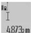
3a BknyBaHe Ha Nacepot H 3a MepeBe, KpaTko npnTHcHete Ha KonTuTe MopeBe (2). N3MepeHata BpeHIOCT Ke ce npKkAke BO peDTo co pe3yntat (c).
PnMpeHbHaNoBKe DoJHKHH eHNO No Dpyro,Ke ce npKakat pe3yIaTHe O nOcneHnTe MepeBa BO peoBN KaDe e npKakKaHa H3MepeHaTa BPeDHOCT(a).
Mepene ha noBpunnn
3a MepeHe Ha NoBpHnH, npiTnCKajTe ro KOnyeto (12)doKeHa ekpaHot He ce nojABn npKa3OT 3a MepeHe Ha nobpHnH
Ha Kpaj, 3Mepete ja 1npuHATA n DOJKNHATA eHNO no npyro KaKo Kaj MepeBeTo Ha DoJKNHH. Pomef y DBeTe MepeBa, Nacepcknot 3paK octaHyBa BklyueH.
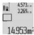
No 3aBpWbBaHe Ha BTOPOTo MepeHb
NOBPIHHaTAt ABTOMATCKn Ke ce npecMeta H
npKaKe BO peoTc PO peyTTa (c).
PiEHNHeHHTe N3MepeHn BpeHocTH CToJat BO
peOBOHTe CO N3MepeHn BpeHocTH (a).
Mepehe Ha BonymEn
3a MepeHe Ha BOLyMeH, pInTnCKajTe ro KOnTuTo (12) IDoKeHa ekpaHot He Ce Nojabn PnPKa3OT 3a MepeHe Ha BOLyMeH
Ha kpa, n3mepete ja wipnHata, donkHnHata n daobouHata eHNO no pyro kaKo kaj mpebeTo ha donkHH. Nomefy Tpnte MepeBa, nacepckno3paK octaHyBa Bknyen.
4.873 10 No 3aBpyBaHe Ha TpeTOTO MepeHBe, 34.892 BONYMeHOT aBTOMaTCKn Ce npeCMeTyBa HKe ce 10.873 npKkaKe BO peoT CO peyntat (c). 1848.76m: IoeHNHeuHTHe N3MepeHH BpeHocTH CTojAT Bo peoBHTe Co H3MepeHH BpeHocTH (a).
BpeHocHTe HAD 999 999 m³ He MoKe Da Ce npKaKaT, Ha ekpaHOT CE noJaByBa „ERROR". BonyMeHnTe ITO Tpe6a Da rN N3MepHe, NOJEnTe rHa NoEINHeuH MepeHa, 3a OndeHNo Da CE pncMeTaat n peHCTpnpaaT HNBHTe BpeHocTH.
KoHTHHynpaHO MepeBe/MHHMaHNO/MakChMaHNO MepeBe(BnDn CnKa B)
PnKoHTHHynpaHOT MepeHe, MepHNoTypeMoKe peNaTHBHO Da Ce DnBKn KOH CNTa, PnI To N3MepeHaTa BpeHocT Ke ce aKypnpa Ha cekOn 0,5s. HAp. MoKe Da ce OdaJeHTe Ha HeKoe pactoJAHne O sNDt, a MOMeHTaHTo pactoJaHne cekoraW Ke 6nDE uHTNBO.
3a KOHTHHynpaHO MepeHe npTnCHETe NOBKe NaHa
fYHKUHOHAHTo KOJe4 (4),doKeHa ekpaHoT He ce
noJABn pNkA3OT 3a KOHTHHynpaHO MepeHe.3aCTapT Ha
KOHTHHynpaHO MepeHe, npTnCHETe ro KOnyTeo MepeHe
(2).
MepebeTo Ha MNHmym Cnyx 3a coonltybahe Ha HajkpatKTo paoTojaHne od eHa qnkcha pepepeHTha Toka.Toa nomara Ha np. npn cooNtYBaHe Ha BepTKaII IN XOpH3OHTaII.
MepeheToHaMaKcMymCnyk3aCOOnHTyBaHe Ha HajroEmoto pactoJaHne OeHnAΦKCHa pepepeHTHa Toka.Toa nomaraHa np.np coonHTyBaHe Ha djarohann.
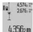
Bo peoT co peyIaT (c) Ke ce npkaKe MOMeHTaHata n3MepeHa BpeHocT. Bo peoBITE CO n3MepeHN BpeHocTH (a) Ke ce nojABn MAKcMaJHATA (max) IN MInHMajHata (min) n3MepeHa BpeHocT.
TaaKe ce npenHwe cekoraw Kora MOMeHTanHa n3MepeHa BpeHOCT HaONKHHaTe e NOMa ODN. NorOEma OD DoceraHata MaKcMmHa OHN. MInHMaHa BpeHOCT.
Co npHTNCKaHe Ha KOnuTeO 3a 6pnUeHb Ha MemOpnJa (8) Ke ce H36pHuaT DoceRaHHTe MHHMaJIH ODH. MAKcIMaJIH BpeHocTH.
Co npntnckahe Ha konueTo Mepehe (2) ro 3abpybATE KOHTNHypaHTo MepeHe. NocneHaTn3MepeHa BpeHOCTe Ce pnpkaKe BO peoTc PO peyntat (c). Co OJHOBO
PnHTNcKaHe Ha KOnyTe MoPeBe (2) KOHTHHyHpAHOTo MepeBe 3aONHYBa OJ NoYEtOK.
KoHTnHynpaHTo MepeHe aBtOMatcKn Ce ncknyBa 5 min. IocneHaTa H3MepeHa BpeHocT Ke ce npKaKe Bo peDor co pe3yntar (c).
NnpeKTHo MepeHe Ha paTojaHna
HINIpeKTHOTMepeHeHa pactoJAHJa CnyKn 3a COONITyBaHe Ha pactoJAHJa, KOH He Tpe6a DnpeKTHO Da CE H3MepaT, Bnejkn HMa npeqKn BO TEKOT Ha 3paKOT Nn Hema ueHa NOBpUHa Kako peFNeKTOp HA paCnoIarAbe. Obaa MEPHa NoCTAnKa MOKe Da Ce npImeHN CaMO Bo BEpTKKaIeH npaBeu. Cekoe OTCTanyBaHe BO XOpN30HTaIeH npaBeu BOi KN MOpHr IpeuKn.
Pomey noeHHeHTe MepeBa,nacepcknO 3paK ocTaHyBa BknyueH.
3a HnHnpeKTHo MepeHe Ha paCtoJaHnJa, Ha paCnoIarAbe Bn ce TpN MEPHN FyHKcH, CO KON MOKe Ja ce CoONuTat pa3NJHn TpaCn.
a) INHINPEKTHO MEpeIbe Ha BnCnHa (BnDn CnNkA C)
Pnntnche ro konyto PpomeHa na yHKunja (4)doeKa Ha ekpaHOT He ce nojabn npka30 3a HndpeKTHm MpeHa Ba BcHn
BHHMabajte Ha Toa, MePHNOT ypeI da e Ha NcTa BmCHa KaKo HdoHata MePA ToUka. IToa Ha HabanTe ro MePHNOT ypeD OKONY pepepeHTHO TnBO H3MepeTe ja TpacTa KaKO Kaj MepeHe Ha DoJIKNHATA (1).
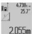
No 3aBpUyBaHHe Ha MepeHbTo, Ke ce npKaKe pe3yIITOT 3a 6apahata TpaCa ,X" BO peoT co pe3yIITAT (c). H3MepeHInTe BpeHocTH 3a Tpacata ,1" n aroJot ,a" CTOJat BO peoBInTe CO H3MepeHH BpeHocTH (a).
b)ДбоJOHINHINPEKTHO MEpeHe Ha BnCnHa (BnDn CnKa D)
PnHTCHETe Ro KOnUeTo PpOMeHa Ha FyHKuJa (4)doEka Ha ekpaHOT He Ce NoJABN npKa3OT 3a DBOJHO HINPeKTHo MepeBa HA BNCHH
H3Mepe TnTpaCHTe,1"H,2"Kako npn MepeHe Ha DOJKNHH, NO OBOJ peDocneI.
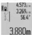
No 3aBpUyBaHHe Ha MepHeTo, Ke ce npKakJe pe3yIITATOT 3a 6apHaHt TaPac ,X" Bo peDT CO pe3yIITAT (c). N3MEpeHNTe BpeHOctn 3a TpaTte ,1",2" H aRoiT ,a" CTOJat BO peOBOITE CO N3MEpeHN BpeHOctn (a).
BnmaBaJte Ha Toa,pepeepHToTo HnBO Ha MepeHbeto Ha np.3aHnOt paHa MePHNt ypeD Ja CTOn TOHn Ha nCTOTo MeTO pIn CTe NoeHNHeuM MepeHa 3a BpEm Ha MePHNt Ipouec.
c) HnHneKTHo MepeBe Ha DoJnxHa (BnH cnHka E)
PnHTCHETe ro konyTe O npomeHa na fyHKunja (4)doKeKa Ha ekpaHOT He ce nojABn npKA3OT 3a INHINpeKTHO MepeHe HA DOJXHH
BHHMabajte Ha Toa, MepHNOt ypeI da e Ha NcTa BmCnHa KaKo H6apahata MePHa Touka. IToa HABaIeTe Ro MepHNOt ypeI
OKONY pepepeHTHOTO HNBO N3MepTe ja Tpacata KaKo Kaj MepeHe Ha donKNHaTa,1".
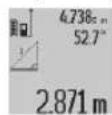
IIO 3aBpUyBaHHe Ha MepeHbeto, Ke ce npKaKe pe3yNTATOT 3a 6apahata TpaC, X" BO peoT CO pe3yNTAT (c). N3MepeHnTe BpeHocTH 3a Tpacata,1" n aroJOT, a" CTOJat BO peoBnTE CO N3MepeHn BpeHocTH (a).
Mepehe ha sdnHn NOBpuHH (BNn Cnka F)
MepeheTo Ha SuHn NIOBpuHH CNyKNa Ce DoBne 36npHa NOBeKe IonoEHNHeuN NIOBpuHH Co 3aeHNuKa BNCHa.
Ha npimepoT co cInka Tpe6a Da ce OpeDn Bkynhata NOBpHnHa Ha NOBeKe SNOBn, KOHMaat VCTa BNCnHa Ha npocToP A, HO pa3NnH DoJXHH B.
3a MepeHe Ha SInHnTe NOBpUHH, nPHTNCKajre ro KOnyeto
IpomeHa Ha cyHKuJata (4), IOneKa Ha ekpaHot He ce
nojABn npKkAOT 3a MepeHe Ha SInHn NOBpUHH
I3mepete ja BnCnHata Ha npocstopo A kako npne MepeheTo HA donJHHN. I3mepeHa TBeDnoct (^,c s t^*) ke ce npKakKe HA roPHNOt peo co n3MepeHn BpeNoCTH (a).IacepoT OCTAHyBa BKnyueH.
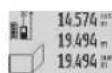
Itoa H3mepete jaOnkHnHaB Ha npBnOtn snd. NOBpHHata aTOMaTCK Ke ce npcMeTa HKe ce npKaKe BO peoT co pe3yntat (c). IocneHATA H3mepeHa BpeHNoCT Ha DoJxHa cToH BO CpeHnOT peCo H3mepeHn
BpeHIOCTn (a).IacepoT OcTaHyBa BknyeH.
Cera n3mepete ja doJxHata BHaBTOpOT sI. PnkaKaHATA noeHneHua n3MepeHa BpeHOC T BO peoT Ha cpeHN H3mepeHH BpeHocTH (a) ce DoJaBa HA DoJxHnHaTBA Cymata OndBete DoJxHn (sum
PnPKaKaHa Ha DOnHHot peCo N3MepeHbBpeHocTH (a)) Ce MHOxKo C3ayBaHaTa BnCnHa A. BkyHnTa BpeHocT ha NOBpUnHata Ke ce PnPKaKe BO peDoT co pe3yntaTn (c). MoKe Da MePHTe DoJKNHH No JeKEn6a Bx The ABtOMatCKN Ke ce DoJaDat N Ke ce NOMHXKaTc CO BnCHHaTaA.
YcnoB 3a TOHa npcMeTka Ha NOBpuHHnHTe e, npBaTa
H3MpeHa DOJXnHa (BO npIMepoT BNCnHa Ta H npocToPOT A) da e NDeHTNuHa 3a CNTe DeNoBn OD NOBpuHHnTe.
MepheHaKocHH(BnHcNkaG)
OTkakoKeToPnTCHETeToKoJIeTOMepeHBeHaKocHH(3) HAekpaHOTKeCENoJABNpNIka3OTaMepeHbHaKocHH. KaKo pepepeHTHO HNBO CnyKHe 3aHaCTpaHaHa MePHOType. Co NOBtOPOIPTNCKAHe Ha KOnyTeO MepeHbHa KocHH(3) KaKo pepeepHTHO HNBO Ke CE NCKOpNCtAT CTpaHnHTeIOBpUHHHa MePHOType, a pNIka3OTHa ekpaHOTKe CE npKaKae CBPTeH 3a 90^
PnHTncHete ro konTueto Mepehe (2), 3a da ja fKnKcnpate
H3MepeHATA BpeHocT Da ja npEeMeTe BO MemOpNJata Ha
H3MepeHN BpeHocTH. Co nobTO npHTckaHe Ha
KoHTeTo Mepehe (2) MepeHeTo Ke npOJnx.
Mepnnotyepn 3aCyByBa nocneHnTe 20 n3mepen HpeHOCTHn HNBHTe pecMeTKn Hn NOKaKyBa Io o6pateH peOcneI (hajnpbo nocneHaTn3mepena BpeHoct).
3a NOBkyBaHe Ha 3aCyBaHIne MepeHa npHTCHETe ro konueto (7).Ha ekpaHOT ke ce npKakke pe3yNTaTOT od nocnEHDTo MEpeHe, nTOa POKa3aTeNt 3a JnCTaTa Ha H3MepeHN BpEOHcTHe (e) H CO MecTOTO 3a MemOpJa 3a
HmepnpaHe Ha npkaKaHaHTe MepeHa.
Iokony npn OndHO BO npTncKaHe Ha KOnyeto (7) He ce 3aayBaat DpyrM MepeHa, MepHNoT ypeD ce BpaKa Ha nocnehdata MEPHa FyHKuJa. 3a da N3ne3eTe OJNCTata Ha H3MepeHn BpeHocTH, NpHTncHeTe ENo OD KOnyHbTa 3a MEPn FyHKuH.
3a da ja 3aaybate tpajho kako KOHCTaHTa MOMeHTaHI O npkaKaHaTn H3MepeHa BpeHOCt Ha DOnKHa, IpXKeTo r npHTCHATO KONUETO (7) DokeKa Ha ekpaHOT He ce Nojabn CST".BHeC Ha NcTaTa Ha H3MepeHH BpeHOCTHn He MoKe Da ce 3aayBa DonOHHTeHNO KAKO KOHCTaHTa.
3a da MoKe Da ja KopnCTHe N3MepeHaTa BpeHocT Ha donKHHATA BO HeKoJa MEPHa cyHKuJa (Ha np. MepeBe Ha NOBpHNN), pNtncHete ro KOnUeTo IIncta Ha N3MepeHN BpeHocTH (7), H36peTe ro cakAHOT BHeC n NotBpDeTe co KonUeTo Pe3yntat (6).
BpHneHe Ha H3MepeHHTe BpeHocTH
Co Kpatko npntnckahe Ha konueto (8) Moke da rHn36pnueTe nocneHDo coonuTeHnTe noeHnHu H3MepeHH BpeHocTn BO CHTe MEPn FyHKun. Co nobekepaTHo npntnckahe Ha konueto Ke ce H36pnuat noeHnHuHtE H3MepeHH BpeHocTn No o6pateH peOcneid.
3a da ro n36pniwete akTyenH no pnpkaKaHNOT 3aHnC Ha IInCTn CO n3MepeHn BPeDHOCTn, npNTCHETe KpATKo HA KOJIpyTe
(8).3aJa jaN36pMWeTe cenataJInCTa CO N3MepeHIN BpeHIOCTn H KOHCTaHTaTa, CST"DpxKeTe rnpNTCHaTO KONUeTo JInCTa Co N3MepeHIN BpeHOCTH (7) INCTOBpeMeHO KpaTKo npNTCHeTe Ha KOnuTe (8).
BoФункилajaМереьeHaSINHINOBpshHHnPnnpBOTo KpaTOKpnTHCKaHeHaKONUeTO(8)KeceN3bpiuwe
nocnHaTn noeHHeHu MePn BpeHnOCT, npn BTOPOTo npntckAbe CHTe DOnKHH Bx, a npn TpeTOTO BHCnHaTa Ha npocTopoA.
Co6npahe Ha n3MepeHne BpeHocTn
3a da rncobepete H3MepeHHTe BpeHocTH, HajnpBO H3BpWeTe npOn3BOHNO MepeHe Nn H3bepeT Bhec od IInCTATA CO H3MepeHN BpeHOCTH. NToa npntHCHe Na KonTuetoPiYc (11).Ha ekpaHOT kaKo NotBpda ce NojaByBa ^ .Itoa H3BpWeTe BTOPO MepeHe Nn H3bepeTe dpyr Bhec OJNtCTaTcO H3MepeHN BpeHOCTH.
3a npOBepKa Ha 36npoT OJ DBeTe MepeHa, yUte eHau nPHTNCHe T HA KOnTuTo CO pe3yNTat (6).PipecMeTKata Ke ce npKkae BO peIOBITE CO H3MepeHN BpeHocTH (a) a
3bnpo Ce nojabyBa Bo peoT 3a peyntar (c).
IIO npeMcTeYBaHe Ha 36npoT,Ha OBOJ pe3yNTaT MoKe Da ce Doaadat DpyrH N3MepeHH BPeHocTH HnBHeCObN OJ NCTHTe CO N3MepeHH pe3yNTaTn,DOKONKy npE MepeBeTo ce npTncHE KOnTuE To Pnyc (11).Co6npaHeTo Ke 3aBpSh N DOkONKy ro pNtncHe Tc KOnTuE co pe3yNTaT (6).
Cobetn 3a c6bnpahe:
-BpeHnCTte 3a donKnHa, noBpHnHa n BonyMeH MeoBHTO da ce co6bpaat. DOKONky ha np. ce co6epaT BpeHnOCTa Ha donKnHaTa n NOBpHnHaTa, npn npNTCKaHe Ha konyeto Co pe3yntat Ce noJaByBa (6) KpaTKO, ERROR" Ha ekpaHot. ItoToa MEPnOT ypeD MeHyBa Ha nocNeDHO AKTNBpuHaTa MEPHa fynKuJa.
- Ce c6bnpa pe3yntaTOT od eHNO MepeHe (Ha np. BpeHocT Ha BOJyMeH), a npn KOHTNHynpaHO MepeHe npKkaJaHaTa H3MepeHa BpeHOCCT BO peDTo CO pe3yIITa (c). C6bnpaHbeto Ha NoeDInHeuH N3MepeHn BpeHOCTHo OD peDObITE CO H3MepeHn BpeHOCTH (a) He e BO3MOxHO.
OdzemaHaHaH3MepeHHBpeHocTH
3aOdzemaHe Ha NImpeHnTe BpeHnCTn npITNCheTe ro konyeto Mmhyc (5),Ha ekpaHOT 3a NotBpda ce nojabyBa,“.Piohatamoohata nocTanka e cInuHa Ha ,DOnaBaBe HImpeHH BpeHOCTH".
Cobetn npa6oTeheTo
OnHTH HANOMEH
Pnemhata leka (17), n3ne3OT Ha nacepcknot 3paK (16) He Cmeat da bndat nokpeneHn 3a BpeMe Ha mepeHbeto.
MepHnotypeI He Cmee Da Ce DnKn 3a BpeMe Ha MepeBeTo (coNcklyuOK Ha yHKunTe KOHTNHynpAoHO MepeBe I MepeHe Ha KocHH).IokONky e BO3MOxHo, noCTaBete ro MepHnotypeI Ha CBpTa nOJnOra.
BnjuHjaHa MephoTo none
MepHOTONOE3aBnCOnOcBETIOCHNteYcNOBnI peFJIeKTHBNHTe CBOJCTBaHaUeINHATA NOBpHHa.3a IIOOBpa BUNINBOCT Ha NacepCKN0T 3pAk npi pa6oTa Ha HABOpEWeH Tepen H ppejAKn COHueBn 3pau, KopNCTeTe Nacepckn Ounla (28) (onpeMa) n cENHa Tabna Ha Nacepot (29) (onpeMa), INI h3aceHeTe ja eHNHaTPOBpHHa.
BnnaHaHa MePnHOT peynta
Iopadn Hn3nKHe eEeKn He MoKe Da ce NcknyuN KaKTOT, DeKa npn MepeHbeto Ha pa3nnH NoBpHnNoaFdo nOrpeHNO MepeHb. Tyka cnaFaat:
- TpaHcnapeHTHn NOBpHmHn (Ha np. cKaIO, BOa),
- NOBpHHHH WTo peΦJIeKTHIpaAT (Ha np. HcNoIlnpaH Metan, CTaKNO),
- npo3Hn noBpHHn (Ha np. n3oNaucNk MaTePnJaI),
-CTpykTpynpaHn NOBpHNN (Ha np. rpy6 MaITepe, npipOeH KAmE).
Iokonye Bo3MOxH0,HaOBne NOBpHHKOpHCTe ZenHa Ta6na 3a Nacepot (29) (onpeMa).
IpeKn npM MepeHbTo ce ncto TaKa MoXHH Kaj HAcOco BnHaPaHN CEHN NOBpHNN.
IcToTaKaHaH3MepeHaTaBpeDHOCTMOKeJaBbInjaat NpOeJIte 3a BeHTnlauJaCo pa3NnHn TemnepaTyPi INHINHePekTHo pIMMeHTe peFneKCHN.
PpOBepKa Ha ToUHocTa n KaH6pHaPaIbe Ha H3MepeHHTe KocHH (BnDn Cnka H)
PeOBHO npoBepyBajTe ja ToHocTa Ha MepeBeTo Ha KocHH. Oba Ce BpHn CO NOMOH Ha MEnyBaHe Ha npaBeOT. NocBete ro MEPnnotypeHa eHa maca H3MepeTe ja KocHATA.CBPTe Ro MEPnnotype3 a 180° nOHOBO n3MepeTe ja KocHATA. Pa3Nkata nomery npKkaKaHHTe n3HOcN CMeE Da H3HeCyBA MaKc. 0,3°
PnroemnOCTaIyBaHaMepHnoTypeMDopOOnHOBaCe KaIbnpa.DpKeTeTo npHTncHaTOKoHToMepeHe Ha KocHH (3).CneTe rynyataHaekpaHot.
PpOBepKa Ha ToUHOCTa Ha MepeHeTo Ha pactoJanHe
ToHocTa Ha MepHnOyypeD MoKe Da ja npOBepHe Ha cnEHNOB HauHH:
-36epeTe eHNO HENPOMeHNBO MeHPO NOppaJe co OJINnHa oOkOy 1 Do 10 m, uJaOnJnHa ToUHO ja 3Haete (Ha np. WInPNHATA Ha NpOCTOpNJata, OTBOPOT Ha BpaTAta). MepHATA Tpaca Mopa Da 6nDE BO BHATpeuH NpocTOp, cENHATA NoBPWnHa Ha MepeHbTo TpeBa da 6nDE Ma3Ha nDobpo peNKeTnpaYaKa.
-Измерето roпогалчjetо 10 natн endho no npуro.
OTcTaNyBaHbTaOJ CpeHnTa BpeHnOCT Ha NoeHNHeHHTe MepeBa CMeAT Da H3NecyBaat MaKcHmAlHo ±2 mm.
3aHnuyBaJTe rH MepeHaTa, 3a Da MoKe INoOuHa da Ja CnopeJeTe ToHocTa.
Pa6oTeHe co cTaTHB (onpeMa)
KopncTeBeTo HA cTaHbO eOC6eHO nOpTe6Ho npn rOJIemnpactoJahna. MePnnotypeCo 1/4"-Haboj (19) noCTabeTo Ha nOoA co 6p30 oCNO6OyBaHe HA cTaTHBOT (27) HnHa BOoBnuaeh foto-CTaHB. LbpcTo 3aBPteJe ja 6p303aMeHNbata nOoA co 3aBPtKa 3aФHKcnapae.
Co0dBETHO NOCTaBeTe rO pepepeHTHOTo HnBO 3a MepeHBe Co CTaHBOT, CO npNTUckaHe Ha KOnTuEto (10) (pepepeHTHO HnBO 3a HABoJ).
Pa6oTeIbe co MePhaTa WnHa (BnHn CnKn I-K)
MepHata 25) MoKeJa ce NcKOpNCTHa nonpeu3eH pe3yTAT npn MepHeTo Ha KocHH. He e Bo3MoJHo MepeHe Ha pactoJahJa co MepHata HnHa.
BmHTeTo MepHnOTo ypeD Bo MepHaTa 11Ha KaKo WTo e npKaKaHaO (25) n3aKnyTe To MepHnOT ypeD co NoCTOT 3a 3aKnUyBaBe (26).PnTnCHete Ha KOnTuTo MepeHe (2), 3a DaTo aKTHBnPaTe HauHHOT Ha paBota,MepHa
HHa".
PepOBHO npOBepyBajTe jaToUHocTa Ha H3MepeHHe KocHH co MeHyBaBe Ha npabeTOnn Co N6eHn Ha MepHaTa nnHa.
PnroEmnOTcTnyBaHaMepHNOypeoMopaOHOBO Da ce KaIbnpa. DpKeTe ro npTncHato KOnyeTo Mepehe Ha KocHH (3).CneDeTe rynatCTbata Ha ekpaHOT.
3a 3aBpyBaHe Ha HauHHot Ha pa6ota,MePHa uHa" NCKnyeTe ro MEPHNOt ypei nI3BaTe Ro od MEPHaTa uHa.
DepeKT - npuHHH nOMoW
Pnunna Tomo
PepypeyBaBeTo 3a TemnepaTypa (j) TpenKa, MepeBto He e BO3MOxHO
MepHHOTypeeHaBOpOJ onepaTHBnTaTeMnpepatypoJ-10Cdo+50°C(BO FyHKuJaTakOHHTNHpHo MepHeJDo +40^)
NoekejTe Doeka MepHnO TpeHe Ja NoCTHne OepatBhata TemepaTypa.
Пиказ „ERROR" Ha ekpahot
Cobpahe/0d3emahe Ha n3MepeHn BpeHNOCTn CO pa3nHn MepHn eHNHn
Co6npajre/0nd3emajre cmo
H3MepeHN BpeHNOCTN CO
HCTN MepHn eHNHn
Aronot nomety nacepcknot 3pak u ceIta e npemhory octap.
3rnoMeTe ro aroNoT nOmeFy nacepckNt 3paKn ceta
LcnHata noBpwnHa npejako pePneKtnpa (Ha np. ornEanO) OHN. npcna6o (Ha np. uPH MaTePNjAN),nnn ambHeNTaHOTcBETNO e npejako.
KopncTeHe Ha cenHa Tabna 3a nacepot (29) (onpema)
H3ne3OT Ha IacepcknT 3paK (16) OHN. npHemHaTa Jeka (17) ce 3amaRnyBa (Ha np. co 6p3a npomeHa Ha TEMnepaIypata).
Mekk Ka n36pHte ro 13ne30Ha IacepckHot 3paK (16) OH. npnMeHa neka (17)
IpeCMeHaTa BpeHocTe norolema on 999 999 m/ ^2 /^3
Ipoen6aHa npecMeTKata BO Mery-uekOpn
Pnka3,>60"HmH,<-60"HaekpaHot
MepHTo nOHe Ha KocInn 3a
mepHaTa FyHKunJa OOnH.
pepepeHTHO To HnBO e
IpeueKopeHo.
N3BpuTe ro MepeHeto BO CnueuHHTO none Ha aROnT.
Pnka3.CAL"H npka3 ERROR"Ha ekpahot
KanibpnpaHeto MepeHbTo Ha KocHH He e
Tobopetro KaHbpaheTo cnope
| Прична Помош |
| ИЗВРЕНО NO 百変徳
редостся Или BO точни
позини. | Ураз委书记 на ча на ekраот и BO
ураз委书记 за улотpeба. |
| Искорichteшие поsprинни
за кал�браваье не се
точно центраими BO
хоризонтalia пли ветокала. | Повторе го
кал�браваьeto на
хоризонтalia пли
ветокална поsprинни и eb.
пковерete ги петхodho
новsprинITE слобena. |
| При лпитскалье на
Колчесу, Мернот урedingсe
помecстел одн се певrtл. | Повторе го
Кал�браваьeto и мирно
држete го мернот урeding за
В��еMuHa питскаьeto на
Колчесу. |
Pnka3 3a HAnonHeTcH 6aTepejata (g), npedypeyBahe 3a Tempepatypata (j)H npka3 ,ERROR" Ha ekpaHot
| Tempepatура на мернот
уreed надвор od
дозволенITE гашици на
tempepatура на понение | Почекajte дodeka не се
постиггсе Tempepatура за
поснение. |
| „ERROR“ на ekpanот | |
| Нановот за понение на
батерида на e тоун | П robерете далу
приклuyнatable врся стоно
Восportа вета и далу
правлино Фунkedиони ра
Micro-USB-кабелot.
Доколку ознakа на у畴от
тpenka, батерида на
deф ekтуни мора на ce
замени odстара на
сервисна сныжва на
Bosch. |
Pnka3 3a HAnonHetoc Ha 6atepnjata (g) n 03naka 3a yacOBHKOT (f)Ha ekpaHOT
CabaKobayevik47H,6poj3
1000 Ckonje
E-nouta: dimce.dimcev@servis-bosch.mk
HHTepHer: www.servis-bosch.mk
TeN./daKc:02/2467610
Mo6.:070595888
D.I.T.Y "POJKA"
JAnI NyKpOBcKn 66; T.LA BToKoMaHaJa Iokaan 69
1000 Ckonje
E-nowta: servisrojka@yahoo.com
Ten: +389 2 3174-303
Mo6: +389 70 388-520, -530
TpaHcnpT
JInm-johcknTe 6aTeepn NoJnEkaH ha 6apaBaTa Ha 3aKoHOT 3a OnaChn MaTePnJaH. BatePnTE MoKe da ce TpaHCnOpTnPaAT cAmO od CtpaHa HA KopncHKOT, 6e3 Notpe6a OD DonolnHTenH KBAHnФKaUH.
Pn npenoc Ha nctte Oc tpaHa Ha TpeH Nua (Ha np. Bo3dywe HtpaHcnpTnnu WneDnju) HeonxOHO e da ce BHIMABA HA cneunjahnHe HanomeHH a m6banaKaTa n 03haknte.Bo TakOB cnuyaj, npn noDrrotBkata Ha npatkata Mopa Da ce NobkA ekcnepT3a onachn cyntaHn.
OtctpaHyBaIbe

MepHnTe ypei,nonHaunTe,6atepnTe, onpemata n am6anaxnTe Tpe6a da ce otctpaHAT Ha ekOLOwKn PnphatnNB HauH.

He nФрпajte nIWItonite 3a Iennebe, МернITE ypeiN, noIIHauHTE n6atepHnTe BO domaunHata KaHTa 3a OTnAnOu!!
Cama 3a 3emjnte oEY:
Cnope ebponckata npektb 2012/19/Ey MEPnHte ypeHn noHaHTe wTO ce BOH ynotpe6a ndeqkTHnte HnNCKOPNCTeHNTe 6aTeepn CnopeDnpeKTbTa 2006/66/EC Mopa Odienho da ce co6epaT na ce peuknpaat 3a NOBtphya ynotpe6a.
AkymynaTopcKn 6aTeepn/H6aTeepn:
JIHTHym-JOHcKh:
Be monime BHHMabajte Ha HanomeHnte BO denot TpaHCnopt (Bnu, TpaHCnopt", CtpaHua 249).
PnO TcTpaHbBe, BrpaHHe 6aTePN Cmeat da ce
H3BaatcmoOCTpaHa HcTpyeHnepcoHan.Co OTBopaHe HaOBBkataHa KyKuWTeTo,MePHnOTypeM0Ke Da CEYHNHT.
3a da ja n3baNITE 6atepnjata OJ MEPHNOYpei, npTnckajte Ha Hero DoJeKa CENoCHO He ce Hcnpa3HH 6atepnjata.
Odbptete rHa 3aBpTKHe Ha KyKnWTeTo H3BaTeJa
06BnBkata Ha KyKnWTeTo, 3a Da rH 3BaAnTe 6aTePnIte.3a
da n36erHete KpatOK cNoj, 3BaAnTe rNoeDmHeHO eEN no
dpyr npknkyoUHTe Ha 6aTePnJa nHa KpaJ n3OnnPaJte rN
nonoHTe.Dpyn n npu ceNoCHOT npa3HeBe BO 6aTePnJa
HMa npeocTaHAT kanaUHTe, KOJTO MoKe da ce ocnoBo
BO cnuyaj Ha KpatOK cNoj.
Srpski
Laser Radiation Do not stare into beam Class 2 laser product
Ukoliko tekst na ploci si upozorenjem nije na Vasem jeziku, prelepite ga sa isporučenom nalepnicom na Vasem jeziku, pre prvog pušanja u rad.
Ne usmeravajte laserski zrak na osobe ili zivotinje i ne gledajte u direktran ili reflektujuci laserski zrak. Na taj nacin mozte dazaslepite lica, prouzrokujete
nezgode ili ostetite vid.
Ako lasersko zračenje dospe u oko, morate svesno da zatvorite oci i da glavu odmah okretene od zraka.
Nemojte da vrsite promene na laserskoj opremi.
Nemoje koristiti laserske naocare kao zastitne naoCare. Laserske naocare sluze za bolje prepoznavanje laserskog zraka.Medutim,one ne stite od laserkog zracenja.
Nemojte koristiti laserske naocare kao naocare za suntce ilu saobracaju. Laserske naocare ne pruzaju potpunu UV zastitu i smanuju percepcjtu boa.
Merni alat sme da popravlja samo kvalifikovano osoblje i samo sa originalnim rezervnim delovima Time
250|Srpski
Laser Radiation Do not stare into beam Class 2 laser product
Do not stare into beam Class 2 laser product

Ja bridinajuma uzlimes teksts nav jusu valsts valoda, pirms izstradajuma lietoanas pirmo reizi uzlimejiet uz tãs kopa ar izstradajumu piegadato uzlimi jusu valsts valoda.

Neversiet lazera staru citu personu vai majdzivnieku virziena un neskatieties tiejaja vai atstarotaja lazera stara. Sada riciba var apzilbinat tuvumesaosas personas,
izraisit nelaimes gadijumus vai pat bojat redzi.
Ja lazera stars iespid acis, nekavejoties aizveriet tās un izkustiniet galvu tā, lai tā neatrastos lazera stara.
Neveicietnekadasizmainasar Lazeraierici.
Nelietojet lazera skatbrilles ka aizsargbrilles. Lazerakatbrilles ir paredzetas lazera stara redzamibasuzlabosanai, tacu tas nespj pasargat acis no lazera starojuma.
Nelietojiet lazera skatbrilles ka saules brilles vai ka aizsargbrilles, vadot satiksmes lidzekli. Lazera skatbrilles nenodrosina pilnvertigau aizsardzibu no ultravioleta starojuma un pasluktina krasu izskirsanas speju.
Nodrosiniet, laimérinstrumentu remontétuvienigikvalificeti remonta specialisti, nomainai izmantojotoriginalasrezervesdalas.Taslaus saglabatvajadzigodarba drosibas limeni, stradajot ar merinstrumentu.
Nelaujiet berniem lietot lazera merinstrumentu bez pieauguso uzaudzibas. Vini var nejausi apzilbinat tuvumaeosas personas.
Nestradajet ar merinstrumentu spradzibistamas vietas, kur atrodas viegli degosi skidrumi, gazes vai putekli. Merinstrumenta var rasties dzirksteles, kas var izraisit puteklu vai tvaiku aizdegsanos.

Sargajiet merinstrumentu no karstuma, piemeram, no ilgstoas saules staru iedaribbas, uguns, udens un mitruma. Tas
var izraisit spradzienu.
Nelietojiet merinstrumentu, ja tam ir pievienots mikro USB kabelis.
Drosibas noteikumi uzlades icercem
Ši uzlades icerice nav paredzeta, lait o lietotu berneni un personas ar iberobežotam fiziskajam, sensorajam vai garigajam spejam vai ar nepietiekošu pieredzi un zinašanam. So uzlades icerici var lietot berneni no 8 gadu vecuma un personas ar iberobežotam fiziskajam, sensorajam vai garigajam spejam, ka ari personas ar nepietiekošu pieredzi un zinašanam pie nosacijuma, ka darbs notiek par viŋu drošibu atbildiges personas uzraudzibā vai ari ši persona sniedz noradijumus par drošu apiesanos ar uzlades icerici un informe par briesmām, kas saistitas ar tās lietošanu.
Pretëja gadijuma pastav savainosanas briesmas izstradajuma nepareizas lietosanas del.
Darbs ar stativu (papildiederums)
Stativs ir ipasi noderigs, veicot merijumus lielai attaluma. Izmantojot merinstrumenta 1 / 4^ vitni (19), nostipriniet to uz stativa (27) atri nomainamas plaksnes vai ari uz parastafotostativa, ko var iegadaties tirdzniecibas vietas. Ar stiprino so skruvi stingri nostipriniet atri nomainamo plaksni uz stativa.
Nospiežot taustinu (10), izvělieties atskaites limeni merišanai ar stativu (sajā gadijumā par atskaites limeni kalpo vitne).
Darbs ar mérstieni (attéli I-K)
Mérstieni (25) var izmantot gadijumos, kad nepiecesams precizi izmerit nolieces vertibu. Izmantojot merinstrumentu kopar mérstieni, attaluma merisana nav lespèjama.
levietojiet merinstrumentu merstieni (25), kā paradits attela, un to tur iestipriniet, nospiezot fiksjo so sviru (26). Nospiezot merisanas taustinu (2), aktivizejiet darba rezimu „Mertienis".
Regulari parbaudiet merinstrumenta precizitatei nolieces merisanas rezimam, veicot kontrlmerijumus ar pagriesanu vai izmantojot merstiana limenrazus.
Lielas starpibas gadijuma javeic merinstrumenta atkartota kalibresana. Sim nolukam nospiiedet nolieces mrisanas taustinu (3) un turiet to nospiestu. Tad sekojiet noradjumiem, kas tied izvaditi uz displeja.
Lai izietu no darba rezima „Mérstienis“, izsledziet mérinstrumentu un iznemiet to no mérstiona.
Klumes - celoni un noversana
Célonis Novéršana
Temperaturas bridinajuma indicators (j) mirgo, merisana nav iespejama
Mérinstrumenta temperatura ir arpus darba temperatas vertibu diapazona robezam, kasir no -10^ lidz +50^ (nepartrauktas merisanas rezima lidz +40^
Nogaidiet, lidz
mérinstrumenta temperatura
atgriezas pielaujamo
temperatas vertibu
diapazona robezas.
Uz displejair redzams klumes indicators ,ERROR
Laser Radiation Do not stare into beam Class 2 laser product
Do not stare into beam

Class 2 laser product
7
」
aaiuU Lg 1
| GLM 80GLM 80+R 60 | الشام
الشام
الشام |
| 26091207.. | 26091207.. | الشام
الشام |
| 1600A013.. | 1600A013.. | |
| \d\d\d\d\d\d\d\d\d\d\d\d\d\d\d\d\d\d\d\d\d\d\d\d\d\d\d\d\d\d\d\d\d\d\d\d\d\d\d\d\d\d\d\d\d\d\d\d\d\d\d\d\d\d\d\d\d\d\d\d\d\d\d\d\d\d\d\d\d\d\d\d\d\d\d\d\d\d\d\d\d\d\d\d\d\d\d\d\d\d\d\d\d\d\d\d\d\d\d\d\rangle | \d\d\d\d\d\d\d\d\d\d\d\d\d\d\d\d\d\d\d\d\d\d\d\d\d\d\d\d\d\d\d\d\d\d\d\d\d\d\d\d\d\d\d\d\d\d\d\d\d\d\d\d\d\d\d\d\d\d\d\d\d\d\d\d\d\d\d\d\d\d\d\d\d\d\d\d\d\d\d\d\d\d\d\d\d\d\d\d\d\d\d\d\d\d\d\d\d\d\rvert | |
| \( \square \) | \( / \square \) | \( / \square \) |
UgUgUba bIa UJll (u) % 100 aSgl ual jol aol oal oal (A
.07/00,03+ 2yUuWJg.9 25 UwO6j8g 0401
0111111111111111111111111111111111111111111
joo 0,29+ yu u g o! Juuu uu uu
60±uJgJUJI gJbI gJgJUJI gJUJI JgJUJ Looic (C
.45 a/0,01+ 1
aalallg jglalng aaiu jll la joc bE
40+Jauuui 1jI a Jauuui Jauuui Jauuui Jauuui Jauuui F
aagoojoguologo gwlqg g jssllnssy 0g 0g 0g 0g 0g 0g 0g 0g 0g 0g 0g 0g 0g 0g 0g 0g 0g 0g 0g 0g 0g 0g
25.8.1.3 (H)
.ogog joc oag oolj y gauog aas
gaiol a>gl jlc (18) Juauiuall gjJgJ,2g0gJwaiai 6c jai
0ssaaa aegj 1 jasal yabaaa aaiy aaiy jg jbjb ayd aai d
aLac pao (g) pss jn nn nnnn nnnn nnnn nnnn nnnn nnnn nnnn nnnn nnnn nnnn nnnn nnnn nnnn nnnn nnnn nnnn nnnn nnnn nnnn nnnn nnnn nnnn nnnn nnnn nnnn nnnn nnnn nnnn nnnn nnnn nnnn nnnn nnnn nnnn nnne
USB. saio no spall nn s k s 1g Lc gLc qj np wll ooc uoguy p joll 1q Juswll .USB saia gJLa USB 1k SjS (uulll jai nswll aLac) USB saio .gJLswn wll joj
Jwll aLac uI I wlaI o 1s sWl J
!aagbll joo jalil aLs
a a a a a a a a a a a a a a a a a a a a a a a a a a a a a a a a a a a a a a a a a a a a a a a a a a a a a a a a a a a a a a
Jn Jn Jn Jn Jn Jn Jn Jn Jn Jn Jn Jn Jn Jn Jn Jn Jn Jn Jn Jn Jn Jn Jn Jn Jn Jn Jn Jn Jn Jn Jn Jn Jn Jn Jn Jn Jn Jn Jn Jn Jn Jn Jn Jn Jn Jn Jn Jn Jn Jn Jn
山
山
aagablln wuall 6e ayaaep
g oJlJU JU JU JU JU JU JU JU JU JU
0j 2.8.6.7.8.9.10.11 0j j j j j j j j j j j j j j j j j j j j j j j j j j j j j j j j j j j j j j j j j j j j j j j j j j j j j j j j j j j j j j j j j j j j j j
jgJ
pSJJJ
g jgssll jjagb aag pdaa 1
Ug snnn ojag. qaiall caiolg all
puiu uig po go aoialgai I ymu
yaaiai waii ooc g plaaiai ulaill
Ua aLs oJgolsswI 5g 4
uall oJgol gJg Jgai I
gai (la12) LgJgJgJg J
oJwL Wioe oJwJnJn
山jolpoac aLa .oWuall
.1aill gga bawj
1y!aJgSJI aSsJI JdWl 4 oJgSJIU logSJIU go jull gio se JbU bU. JwJ jJb a9K Lc
gag pss saa aagol
aagai alolss j 1s j 1jaoi
Jgl Jlaeewk jols kswp
g g u 1000000000000000000000000000000000000000000000000000000000
wJWJWJWJWJWJWJWJWJWJWJWJWJWJWJWJWJWJWJWJWJWJWJWJWJWJWJWJWJWJWJWJWJWJWJWJWJWJWJWJWJWJWJWJWJWJWJWJWJWJWJ
uall uac jj jull gaw ay
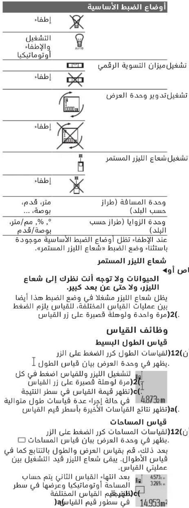
4g|jolw|JLcjj
uJJI JIg
bawuJgblw
J 1 J 1 J 1 J 1 J 1 J 1 J 1 J 1 J 1 J 1 J 1 J 1 J 1 J 1 J 1 J 1 J 1 J 1 J 1 J 1 J 1 J 1 J 1 J 1 J 1 J 1 J 1 J 1 J 1 J 1 J 1 J 1 J 1 J 1 J
.(1)JooJIOOoOoOoOoOoOoOoOoOoOoOoOoOoOoOoOoOoOoOoOoOoOoOoOoOoOoOoOoOoOoOoOoOoOoOoOoOoOoOoOoOo
Jalai adbg
aJlJIJI JIeJIJIaJIJIaJIJI aIbgsclu JIJIJI JUJIJI JUJIJI aJg (6)JJJI bJIJIJIaJIJIaJIJI aJIJIJI aJIJIJI
joojj jai jai (a) wai aq jaw g uai jia jia bao sao. wai q
(5) juji g1 (11) 1j jj ljc buaa jb a60g aui 1
Lgul JUJ LsWuJALdac pU 1. gao pi jui diojll oJI
g jaialldojogolsswlll jS wglcaglgjdsywlglq
J 8. (Lalwll wu g Jlll JnW Wulai I JnK 8 Ls Wuaill
I 024120m
()()
6j21UwLgJ 09 aJg
wul 20 jal bao wulll ooc gai daq jai (j) wsc ujjg quguag .(g) wul
JKwSsIgWgGgJgW .aiaoLguaowuagqioUsawg.
j) 10
aagj jge bssal 4(jb j)
Jc JsW eaijI wuq uoyol oag q
(a) wai jgaw "a" agljll 2.055m
UeJlU JIJI Ue gJalI UJll (D(jgJlJI)
aagj jc bbs4(j)
JU 150
.2"g"1"LwlllglbI wOy
aIwlld jyj yIy IyIy
4573
"2"."1" aIwlll wIyIy JyIy .c
(a) wJJI gJgW g"adglj3.880m JwJc) wJall gJGWIJI JI SbJl (wJll aJdJIaJI JIJI Jn
.
E(jgai jbl) gblw wlaJmu wlaJI (
Jg j 4(j)
gai jui yie wai ooc gog jaoi
ai, ci. ie iai yil wai ai abai
wai ggi jai uiguall uag wai all ooc
.ugai wai sic uall gaoLs "1" aiaai
aJlauJI aai jI JIJI IJI JIJI 4738.
)c-wwwWwJaiIgjbj.1
(a) wai jg baw a"aa glg 2871m
F(jgJjbl) jI JdAaLwU
Egoo oL Ugauu uJUaI aalua wag
. 0uue IeaijUo Jiaoo gBw taaluo
aIaaI aalauu Iuaia uuuu uuuu uuuu
aolio LgiSg A oJauu Ieaiu uoi uu
j j l 111111111111111111111111111111111
sic jll glos A oal alal wol p 1001 (cst.) waiall aol qal .ugll wlaq 1001 jll qai. (a) waiall aoal gll
jw g aagssall wlll aal al aal l pww qg aol! sall no uysu .c) aill (a) wll g jwai o dao all wll
UwIaJr aJb
jll lgl bdoi wai jg 2eBull oal oag g jabg (5) aui ao sial ogbai. “, sii . Egoqol
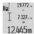
JssI 1s
dolc Ula
a(17)JUaWJwSdAaBjg jy JUaJI 16)JUJI IJUaJIaIcJWJWJUaJIbOJyJy JUaJI (JUJI WJUaJIJAuJIIJAJIgJUJI JUJI gJUJIaIeJUJI
jll jla o jgo Jolgc
aag aai kglc wlll glai agg 1 aag aikso . aaiabai wksii 2 gag sic g aJIg jauil sic jjuI glw (28) JJUaag oJbai sssw, aag aaw aw gl (Lalall) (29) JJUaag aaglg (Lalall)
wll aui j ojgo Jolgc
wai jie aibla wai qi iinwnj k sna. 0aiae gbw wai q sic ayluuauu IJWl
jil) jll uu yue g a (H ojjal
wlll lglg jjjl glbol wll
aai aas Lla aagg Jglj gag k
wqall qg daig jbuai,dail)7(ugdo
joojj oag g jg jbbu jU, CST"b0a s8.
aui aai yiai laa wai jao
wla) wla aabg jglll wla aolssw Lwall aaJj bao1. (Lio daIawll)7(0
baaill Jda no sWu paa, ygejll ssll jai aiill jj lc)6(
JUJI goo
jll lgl aagl balsall jn jS8( 1g jy 0sall wai gao oagal gai all jn jS. uai all jy dall wai gao Jssu
S ACD = S COD + S_ DCE
LwJwJGjWJUaJIg aJg JIuJIaJI gJUJIg.8)jjI Jc oag
aag jj bai “CST, auiu dajg JolJU Cgui uai g bao (7) uoi jllc oag adgl
sic yu jy daiu wu q aag u 8) jll lc ojg jou 8
gao gao ayu uall bsall sicg .
eai jia gao ayu all bsall sicg x JgIB A.
UwuaIgao
yogai jyuyu wllgao yogai yj
ywali aiao no 1sui jial gwlal alac
oag laaayl.11) sij jll lc bdoi
gl ss ayilwai alac gaj *wjell
.owll paaiae no wae daqjuaia pi
1501 wJll gao a920 J 9645.
LwHuaUuJjG)6 27.327.
gaoJI I .a) wJll pJbWJ
36972m
auiiOgaojUkagaailluua
Lwaiiao ggu ggl uau aLac (11) 11jll jIc baxll pI IJg
ucagao LAc qilp oJc wai
6(11) JIc baxll qIb
gag gagbawlg jgbal gag gag k y - gglgbagag aIla g .gagllgagge 1j Ic oag alg baoa Iic ag bia aLo 0ag (lb) "ERROR, (6) uJl aaii iag g JI Ls y wai Isc Jauu .og Jai Jai Jai Jai Jai Jai Jai Jai Jai Jai Jai Jai Jai Jai Jai Jai Jai Jai Jai Jai Jai Jai Jai Jai
-()ggljgglg 10uwwlc)dydu
gj jy.(yll aag,aegjll jy 100i jy g g ylo jso yuall agluo .dyaas gauu uuulcog uol
aaiiaaii iaiaii iin jn glaill aai 2
2UwJU
(gg) gglgll lalal abwlg jolll psslpsj kss sll aalll btt pssy wll ooc g. gglgll lalll
aUgU 1/4 aUgU)19(
gall lalololol)37(
pokl. gWkI gUgsll no yu
yull aywaaonll cUg Uabwgl
Jolll go wqll llacLgRyssy ssGswll bdo
(10) jll lc bwhll Ula no pugll L
.(agU| uWkLgWwll) aWli
(K-1jglal jil) waiai aSsw plssw ly Jaoi 25( waiai aSsw pIaui (kgs)25( iWai joc nSoy. Jaiai waiy a9s jsi aai .waiai aSsw pIaai I go
251aAsw g wqll oocg 1uLpogogjgauuagogo glos 1j pssuLy wqall oc
(2) wJj Jc b. (26) JlQy Jw
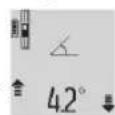
aac jno pabil lll wuag aasaa a .wauall aaw agwull ujiogai guiw q 1yjao wuall oxc oayb yogai n yu wuq jbuai Ie pala. cjcuglaill sl j 3) all
0sc-1ably 《wJJIaW》JswI Egi JgK. wJJI aW uLojag WJJI
aJgUw-1
a
Sahba Technology Group
J 1
+964(0)7901930366:
+971 (0) 4 422 1898:J
duraid@sahbatechnology.com:JgJJJJJJ
#
15c b@og oIeall J
0scgglj
wulolsc
Lc bssalw
wJ 5d JkWbWJ
jll
j.jllbaw
psjoll jw aJg(aJy
jJIJI)j(,JUg ERROR
yI yogill 1
0a0jda jao
JwUjJdJU
Jd
agawaljwll oJ
pJol jw JUJg"jUJIgERROF
yoljooag
j 15
LsWuUgU LwJ
P
山山山山
USBJsu josgSlo
yog aJg.
jI jieiJg jqjI jor
JyBgJU JaJl
jjo uo joo
μg aSjμjUjdo
p5jll jw wJL (j)g( aclwI jofof
jolldag
jLspolaiwlc
agg jss oos sij
yo ylo81 gJyLo USB
J 1
.
dgaoso uc wulai dui
( wS2 - wS1) = 12
LJ1:10) 1g Jsw
(aJJI
J 1
(16) jull aew
91 (16)JJUaWJ 17 JuaWJ aWsc
(17)Juaiwaiw
1
Gssg 15gimboo po
j山山abaiSip
EawlJwOglc
.
wll 0e uww g ju y 1uJU
jllbcnsallieeggioueK
ggljuiai jbcdoi
L
jjg (2) wlaill jj lc
juijjj/ajsljjg
bfo 8(8):abylg
U
1521 aaoa aol jyjw laal ooc goo
aJg. wuag aLac Js go oIbgl
j0j0g j0j0j0j0j0j0j0j0j0j0j0j0j0j0j0j0j0j0j0j0j0j0j0j0j0j0j0j0j0j0j0j0j0j0j0j0j0j0j0j0j0
1gdlaloloojogbgojo
0gJgSdJdXcUwUJlJfJnWpJ
JUWUJIIOUCuAulwuuuqJusJULOJU
a0oJolai 11 Jalil Jla u w y Lao do sa
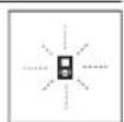
#
p. p. 3. u w u g j u g u g
jIgZ.l.abgbjIddj7
jUjU
wgc 2014
:+21671427496/879
+216 71 428 621 :Uw≤Ug
sav.outillage@tn.bosch.com:
oJaiJI aJJI U|LoK
Jd
26255 1g
00971 (0) 43090920/3090930 :
00971 (0) 24017745:
00971(0)65932777:ajwJ
00971 (0) 3 7157419 : √ √ √ √ √ √ √ √ √ √ √ √ √ √ √ √ √ √ √ √ √ √ √ √ √ √ √ √ √ √ √ √ √ √ √ √ √ √ √ √ √ √ √ √ √ √ √ √ √ √ ∙
:gjSJxJy
Mallappa.Madari@centralmotors.ae
#
aJlllJg awwgo
Jolal joljll oolol .sjjg
+967-1-202010:
+967-1-471917:μsLg
/tech-tools@abualrejal.com: 已 _ 1 ^ 已
yahya@abualrejal.com
JJI
gilgolSd joll guiu Ugglg
Jai gao jia xianqian jia slgall
bgw ayu yall ngs Ujll lpc
.
jlll:10) jil jlr jlr jc lllj lo sic aIbogu uagu,(jawasg
a oaii i 1000
jau ylo sic ojBJI slgoJI Jai uao
. aJlJI o 10 daiw sljoll
auijSll oJn jalil
0jagwulallssnoolall
aJbJgglgJgJgJg
Lgaiuui jgluc aull lcaabla
aill 8ley alalil lalail jslal
jwll ojg wuJ 1 ssc Jy
2006/66/EC gjggl aagll jaswU
g aJUU U JUUL/psJUJG
aayjby lqio yaloll pyl ola lc us aIgannll
ylaill jslal yaiuji bjc aiui Lc abdlo
aaiJl oLcAduJI
:UJUJI/psjall
gulUugl
jbl) jaii jg d gdluol
.(319 aoiJ,“JoiJl,
J
aJgJdJdSrootsArabiaJjJl
JU LLOJ, JUJL EJU
11623J
μgssio110068
+96264398990
:gjSjI jllbosch@rootsjordar
U
jio, acll jgul aabio1 aob.16Jlu
3
ggsuJggsaH13002
24810844:
24810879:uSla
josephkr@aaalmutawa.com:JgJlS!
#
p.o.3.jwolwjglinqab
449-90 gg sio Su ggsio
0
gjgJ
:9611255211
service-pt@tehini-hana.com:JgjS!
U
Robert Bosch Morocco SARL
gjoo ssoo ojjol jlu53
20300
+212529314327:
sav.outillage@ma.bosch.com:
Jlac
p.p.1w glaolg jililo
baa,(5gj.131yjg jio
Jlacaibaw.112:5uulgSJI
aagssll aayall aSlaal
(gSus) aiaiUaasuauu aS
aJdA2431-21431049:g
a. gzzwll
433L-00966(0)126920770:
-00966(0)114093976:UJUJI
30/34/39-
00966 (0) 13833956 :ploJI
M.Zreik@eajb.com.sa:ijjSxj
UJgW
auiuullssallxssawwgo
joc jgwh -aolglwh.
009631122414009 g +963112241006 :
00963991141005:JUgJU
rita.dallal@ hotmail.com: igjSJ|D
320|
algo yalil
Uuaaiauug uo 100
Lull ooc JjI jIgI pss
J 1 J 1 J 1 J 1 J 1 J 1 J 1 J 1 J 1 J 1 J 1 J 1 J 1 J 1 J 1 J 1 J 1 J 1 J 1 J 1 J 1 J 1 J 1 J 1 J 1 J 1 J 1 J 1 J 1 J 1 J 1 J 1 J 1 J 1 J
IJUJgss JJJwLs
1sSgS sI JJLw oLsw S 1sJdsJfJ Lw g
Lg g 1gJ Lg Jg Jg
JSSgS.wwI Oddj8 1JfJUw g Uw 8 sU
9 9g j sIgWls lJl s L d Jn g bL Gaa nJn JnJnJnJnJnJnJnJnJnJnJnJnJnJnJnJnJnJnJnJnJnJnJnJnJnJnJnJnJnJnJnJnJnJnJnJnJnJnJnJnJnJnJnJnJnJnJnJnJnJnJn
JiabI JJJJwOls jI sIgJ G,JSJyJyJyJyJy
g g j 00
J.S.aaS oIaIw Ugguo oluW sJLs Jpa OJgai I u
.
g u g w o slawl pks 4 jj l j ksg s j
Do not stare into beam Class 2 laser product


- cumi Laij j
oJw dJwJ JwW Cwsy
CwsyJgJ JgS Jj d oLsws
.
g jjgljglg qg 1u g g uulg uui
.1sij 0jdu jao cwi J Saa dsiu jgmu,sljol ssw oJ .JJ
<
Laaa aJj
pJjLai
j jw c uog (g) gjw wu wu wu wu wu wu wu wu wu wu wu wu wu wu wu wu wu wu wu wu wu wu wu wu wu wu wu wu wu wu wu wu wu wu wu wu wu wu wu wu wu wu wu wu wu wu wu wu wu wu wuuw u
s o s jjw o kws o slawl p 0g j g j g j g j g j g j g j g j g j g j g j g j g j g j g j g j g j g j g j g j g j g j g j g j g j g j g j g j g j g j g j g j g j g j g j g j g j g j g j g j g j g j g j g j g j g j g j g j g j g j g j
()
Jg jjjw ojjj 1s ojjj 1j
jIjI jSjI aiq o slawl SjL 5oJsi
jLQULOOSOJLqJJsOjSILJJI J “Guluaa,duuSgaj),uSISd jUJSLJJI UoJlgic.323 dao .JggsJALNJtiuui OjUdSjLJUojooagj山
oogwjg syl d CwI j jilai, CwI oJ Jw .gwi ggi y Ssiiaai bwg yu g 0 w .y i j 0 ggi du ggi u ksi
.
glgl jlsl oJ
jju jJwog
a|j|ol|j|j|g j|j|j|j|j|
(slooglo)Sloosy
s j silgi llos suiuugj g (sui
JlJgao ju oJ
oJsljIjI jsl
.
jU 1y UJU JU LgU
sulai juiS yjlgaoi
a baw ogs jolulj w Jaw gosawdawao Sgogil gblao.5gws0o1sJw (c) a
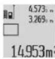
jlaa (sloabw J Ssi (sS oJil
.ij|j|j@ (a) 5u oj|j
005 0j
JLwSgLojI gJgJol jJl dSis
WuWuOoGgWuOoJol dlai
siLao gJyJooBaw JgJl OJslil Jj
sKgOJxil J"1"JooUg 0Jsi
SgOJxil JooJol ooi Jow
JX"OooJooJooJooJooJJ
ogooJooJooJooJooJooJooJooJooJooJooJooJooJooJooJooJooJooJooJooJooJooJooJooJooJooJooJooJooJooJooJooJooJooJoo
.
(Fgagduusegaj)jglgsbawgol jolil gao jlgao jgsygbaw ssojol jglj go Sjiao elaij sylj dSgbaw siju
JgS Jn SjBpai y jy gajl jia 1u Lg A uLsblgla jgl a 1u Cw y B Uglao slgb
Jagda JgBabw sljol jy
JwLai Jd s Jwq Jl b l (4) SjLac
JwJb JgBabw oJal jsi
Jol ai Jgb sOjdl si I A gla JI Jdo JwJ"cst"(sOjdl Jdo .Ji
JgO OJLai a) sOjdl
Jilo Ggblg jiyam
ojdljlgBgbl jI j 14574
Sjlogil gbdaw. Ss 1949
SjOJdjl Jdao Jg aWLa
Jdao JdJ .gsw o0dsuLac 284.106m
Jdao Jlqbw Jg bQoJdJ
Jwgljliqam JJg..JdJg (a) jxl
.ilo 0g
clu oolgS jy jla s yjdl s yjdl j. cwi ci ddo abai jI g1 l sggac bga n eolgim du liu sls .si Su Ss
Sj dlalg jisla jisla sgs ojl 1y jio jol .CwI Cui Ddo aboi .sios ygo bga joi p
aui jw j 1676j 1 J 2676
oJil jdo) a(jsljdo 43562m
"min"(jdlg)"max"(
10jol ojl jnl .s
10a d s g w 0000 jw y do oJil g
ojil jI jjlg jgs.0000 oJil
. wU Jg jsiLg
a0dss joljwagg8(jdo 5gwa 1gulla ljsl
(sijd aS u)2(sui jsi
Juugd uag a.suao o1s gaiic ( 2) 0j sds
JSGg jgb ddd5juy Saaos ojl 1baw jSsOjI sao uai .sgw O golal .gauo ouiu la (c)
aaiuua u c jgbu cIluo 5u oJil
aLs ypaiaa mepg jy 0j1s i oJsi gai aiau oJgO du ds JgIauo n s L juii gji jio Su jn suu y go Siiu u 5u kai cag y la jy gao daos u sis Gao gao bao jglgo gS OJsiu jnl jl. daji gag jusbdaig jm .Sdlaaiw lsgac qj j 0j1si jolai wlaiae bclg q
jw g jS i Ss ojl sll dla JJJg jy .silo y
a aaiu o jg b g uo 5s ojl s1j
qil Sos ay dS yog g s ojl s1slo
.5s aawoo lggo lolao
(g)paoe e lajI (a Cgai 4 (4) jSLac gao dos paiauue e aoljI sOJlsl JwLai J .
jLwgljg joliljlal dSs sJ 1julu. uuiy joi jolil abai siilam g juiy oao jog jg jus ojlil .iSj0jnil (1) moo Jgb sOjnil
s o j s j s o pai j w J"X"o gauu u u u dui .gaw o o sl uai (c) aui jw g"1" cluu oj si j slao oj sll s0000
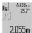
.
oJgS oJl jglgjgbio y 7) aos o
ogjol gjol jn jai dnnj jwai
oljg (e) lgjlil cuiu uas
ojlil (s) oJau s bgl
.ogmo jlo o o o J
Lgjol jy (7) aos s nn j
sJSLAC nJd a (s) oJl jj
CJUJ SJJ GJGJ
ojslj jI JSLAC sl da s j L
Jg jol g oj sil jdoo cui ojia jgbio a J 7) Lqjsl CwJ daS Sg j.og wosuai "CST" Jauai J li Sswag jbjn jgai J Lqjsl CwJ da S OJ
Jg b jol si jdoo sji olaow jgbio a (7) Lqjsl CwJ daS (abw Juaa dawg aga Jlaji ygo g .6) ssu
5oJsiJoaJgSsuogai
pai j s jgi (8) dss oig s j s g f l
s s oj s i j sao n nn jai y s s oj s i j s a s s s
g s s oo j j j .s s 0000000000000000000000000000000000000000000000000000000000000000000000000000000000000000000000000000
olgS juug u jlg s baw yjdl sJSLoc J
y, gw Lo Su oJil jdoa (8) daS
pogw jue.xB lqgb daa pgs jw qk
A gul eai
ooljuljg
1j j j j j j j j j j j j j j j j j j j j j j j j j j j j j j j j j j j j j j j j j j j j j j j j j j j j j j j j j j j j j j j j j j j j j j j j j j j j j j j j j j j j j j j j j j j jjjjjjjjjjjjjjjjjjjjjjjjjjjjjjjjjjjjjjjjjjjjjjjjjjjjjjjjjjjj
(c) 10000000000000000000000000000000000000000000000000000000000000000000000000000000000
oJslil jIggs2 oJglgisB 14574
SsOjolal JdAa. 23676
Jl dai y a 43.170
aJlqDjLdaiy aB
)Ugbdggaaagaaagaaagaaagaaagaaagaaagaaagaaagaaagaaagaaagaaagaaagaaagaaagaaagaaagaaagaaagaaagaaagaaagaaagaaagaaagaaagaaagaaagaaagaaagaaagaaagaaagaaagaaagaaagaaagaaagaaagaaagaaagaaagaaagaaagaaagaaagaaagaaagaaagaa
:glj dslj gac s wgS sb
gdiSjLw slqWg sJyJlsl J g doli j 10sJiJI oJaiI I g 2012/19/EU gJgJlJgJgJgJgJgJgJgJgJgJgJgJgJgJgJgJgJgJgJgJgJgJgJgJgJgJgJgJgJgJgJgJgJgJgJgJgJgJgJgJgJgJgJgJgJgJgJgJgJgJgJ
:Gol (SjJy/5jJw SjJy
:gjogj
Jaa 331
I 1
jJ jI.8g0sgl ngyaa 1jgs oJl JlJl CwI jSao aSy J .8g
Jljl (s)jdl jIJI JSLU 1uJgJ L C
. 0laW JU U uu Jua Li sJL
Sis Ia Jdu y g ggl Jd uu (SG) Sla
.0gS Jauil j Sggl Gg .g W JU li
uuw g uis Iu Sj Uo a Jy Sj Uu
Jua Uo uu Jue L qba Slstis
Jus g g jlu Jlu Sdo Jlu Jol
. 0jI Ogs JLUI Ue Jd CwU n sa
uugw9 CJr
olw s jjg g josj
bog sly g jolil jj1 jai g jao g slaq
. jy pai osw daa aag bga cS alw y
. jy olji jai ojlgaw l g s ojlil jj
abge cIaIoo Iw lg w Js g s oJlil jj
g jj Jaiw Sj jS gjj jS Sj g o s w slgo jy jS jI .s i o slaow gbo j .si (sjss
suii jui jil (si)17(Su si dS i
sS 1 sJg jil Sic 1 1 g jj j j j
juiu u o jglua g lo
JU JU JU JU JU JU JU JU JU JU JU JU JU JU JU JU JU JU JU JU JU JU JU JU JU JU JU JU JU JU JU JU JU JU JU JU JU JU JU JU JU JU JU JU JU JU JU JU JU JU JU
juiuua oogluooogBoscha uo Jus
go 1aIg 0JL Jaw 2Ig W.
la, Ls y Iab g w Jaw g UgW dig sUj
Lg oJaw
.