PGS420SE - Garden shredder SCHEPPACH - Free user manual and instructions
Find the device manual for free PGS420SE SCHEPPACH in PDF.

| Product type | Petrol garden shredder |
| Brand | Scheppach |
| Model | PGS420SE |
| Dimensions (L x W x H) | 2200 x 700 x 1110 mm |
| Weight (assembled, without fuel) | 142 kg |
| Max. branch diameter | 120 mm |
| Number of blades | 3 |
| Blade dimensions | 150 x 55 x 5 mm |
| Engine type | 4-stroke, 1 cylinder, air-cooled |
| Displacement | 420 cm³ |
| Power | 9 kW / 12.2 PS |
| Speed | 3600 min-1 |
| Fuel | Unleaded, min. 95 RON, max. 10% bioethanol (E10) |
| Fuel tank volume | 6.5 L |
| Engine oil | SAE 10W-30, capacity 1.1 L |
| Sound power level (LwA measured) | 109.3 dB |
| Sound pressure level (LpA) | 99.2 dB |
| Wheel diameter | 360 mm |
| Loading height | 1050 mm |
| Max. loading opening | 460 x 380 mm |
| Battery voltage (depending on model) | 12 V |
| Battery capacity (depending on model) | 18 Ah |
| Safety devices | Emergency stop, safety bracket, protection against unintentional start |
| Routine maintenance | Oil check, air filter cleaning, oil change every 50 h, sharpening/replacing blades |
| Intended use | Private use in garden, shredding branches, hedges, plant waste |
Frequently Asked Questions - PGS420SE SCHEPPACH
User questions about PGS420SE SCHEPPACH
0 question about this device. Answer the ones you know or ask your own.
Ask a new question about this device
Download the instructions for your Garden shredder in PDF format for free! Find your manual PGS420SE - SCHEPPACH and take your electronic device back in hand. On this page are published all the documents necessary for the use of your device. PGS420SE by SCHEPPACH.
USER MANUAL PGS420SE SCHEPPACH
natural_image
Technical line drawings of two agricultural machinery with wheels and motors (no text or symbols)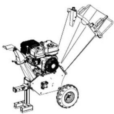
natural_image
Technical line drawing of a mechanical pump or scrubber assembly (no text or symbols)
Made in P.R.C.

PGS420, PGS420E, PGS420SE
| DE | Benzin-MesserhäckslerOriginalbetriebsanleitung | 9 |
| GB | Petrol garden shredderTranslation of original instruction manual | 39 |
| FR | Broyeur à végétaux thermiqueTraduction de la notice originale | 64 |
| IT | Trinciatrice a lame a benzinaLa traduzione dal manuale di istruzioni originale | 92 |
| NL | Benzine-meshakselaarVertaling van de originele gebruikshandleiding | 120 |
| ES | Trituradora de cuchillas de gasolinaTraducción del manual de instrucciones original | 146 |
| PT | Picador a gasolinaTradução do manual de operação original | 174 |
| CZ | Benzínová nožová řezačkaPřeklad originálního návodu k obsluze | 202 |
| SK | Benzínový nožový drvičPreklad originálneho návodu na obsluhu | 228 |
| HU | Benzines késes szecskázóEredeti használati utasítás fordítása | 254 |
| PL | Benzynowa rozdrabniarka nożowaTlumaczenie oryginalnej instrukcji obsługi | 281 |
| HR | Benzinska sjeckalicaPrijevod originalnog priručnika za uporabu | 308 |
| SI | Bencinski vrtni rezalnikPrevod originalnih navodil za uporabo | 334 |
| EE | Bensiini-nugahekseldiOriginaalkäitusjuhendi tõlge | 360 |
| LT | Benzininis peilinis smulkintuvasOriginalios naudojimo instrukcijos vertimas | 385 |
| LV | Benzīna nažu smalcinātājsOriginālas lietošanas instrukcijas tulkojums | 411 |
| SE | Bensindriven kompostkvarnÖversättning av original-bruksanvisning | 438 |
| FI | Bensiinikäyttöinen oksasilppuriKäännös alkuperäisestä käyttöohjeesta | 463 |
| DK | Benzindrevet kompostkværnOversættelse fra den oprindelige betjeningsvejledning | 489 |
| NO | Bensindreven knivhakkemaskinOversettelse av den originale brukerveiledningen | 514 |
| BG | Бензинова дробилкаПревод на оригиналното ръководство за експлоатация | 539 |
| GR | Βενζινοκίνητος τεμαχιστήςΜετάφραση του πρωτοτύπου των οδηγιών χρήσης | 568 |
| RO | Tocător pentru resturi vegetale pe benzinăTraducere din manualul de exploatare original | 597 |
| RS | Seckalica sa benzinskim motoromPrevod originalnog uputstva za upotrebu | 624 |
| TR | Benzinli bîçaklı doğrayıcıOrijinal kullanım talimatı çevirisi | 650 |
27
Günzburger Straße 69
D-89335 Ichenhausen
Hinweis:
- Position MAX - "Hase"
Hinweis:
Homepage: https://www.scheppach.com/de/service
Explanation of the symbols on the product
Symbols are used in this manual to draw your attention to potential hazards. The safety symbols and the accompanying explanations must be fully understood. The warnings themselves will not rectify a hazard and cannot replace proper accident prevention measures.
 | Before commissioning, read and observe the operating manual and safety instructions! Wear safety gloves! |  | Danger! Rotating blades.Keep hands and feet outside of the openings when the machine is running. |
 |  | ||
 | Wear safety goggles and hearing protectionWear sturdy footwear! | 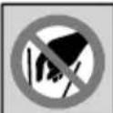 | Attention: Risk of injury! Do not reach or climb into the filling hopper or ejector chute during operation.Protective and safety devices must not be removed or tampered with. |
 |  | ||
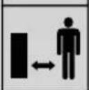
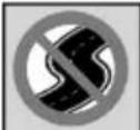 | The product does not have street approval.Important. The exhaust gases are toxic. Do not operate the engine in areas that are not ventilated. |  | Make sure that other persons maintain a sufficient safety distance. Keep unauthorised people away from the product.Hurled objects and rotating parts can cause severe injuries. |
 |  | ||
 | Attention: hot surface - danger of burning!Naked flames or smoking near the product is strictly prohibited! |  | Remove the spark plug connector prior to all maintenance work.Attention! Flying objects can cause injury. |
 |  | ||
 | |||
  | Attention! Failure to observe the safety signs and warning information affixed to the product and failure to observe the safety and operating manual can result in serious injury or even death.Switch off the engine when refuelling.EMERGENCY STOP switch |   | Clean the air filter according to the instructionsSpeed adjustmentHare = fastTortoise = slow |
 | Tank contents Maximum wood diameter |  | |
 | Guaranteed sound power level Checking |  | |
 | Choke closedFuel valve open |  | Filling in oil |
 | Engine |  | The product complies with the applicable Serbian directives. |
 | Before commissioning, read and observe the operating manual and safety instructions! |  | The product complies with the applicable European directives. |
Explanation of the signal words in the operating manual
| NOTE | Signal word to indicate a potentially hazardous situation which, if not avoided, could result in product or property damage. |
| ⚠ DANGER | Signal word to indicate an imminently hazardous situation which, if not avoided, will result in death or serious injury. |
| ⚠ WARNING | Signal word to indicate a potentially hazardous situation which, if not avoided, could result in death or serious injury. |
| ⚠ CAUTION | Signal word to indicate a potentially hazardous situation which, if not avoided, could result in minor or moderate injury. |
| ⚠ ATTENTION! | We have marked points in this operating manual that impact your safety with this symbol. |
Table of contents: Page:
- Introduction....42
- Product description (Fig. 1 - 27)....42
- Scope of delivery (partially pre-assembled) 43
- Proper use 43
- Safety instructions 44
- Technical data....47
- Unpacking 47
- Assembly 47
- Before commissioning 49
- Operation....50
- Cleaning and maintenance....53
- Transport....54
- Maintenance 54
- Storage 60
- Repair & ordering spare parts 61
- Disposal and recycling....61
- Troubleshooting 63
- Declaration of conformity 676
1. Introduction
Manufacturer:
Scheppach GmbH
Günzburger Straße 69
D-89335 Ichenhausen
Note:
In accordance with the applicable product liability laws, the manufacturer of this product assumes no liability for damage to the product or caused by the product arising from:
- Improper handling
- Failure to comply with the operating manual
• Repairs carried out by third parties, unauthorised specialists
• Installing and replacing non-original spare parts - Improper use
Note:
The operating manual is part of the product and contain important information for safe, proper and economical operation. Please also observe the applicable national regulations. Read all operating and safety instructions carefully before use and only use the product as described. Keep the manual and pass it on when you give the product to someone else.
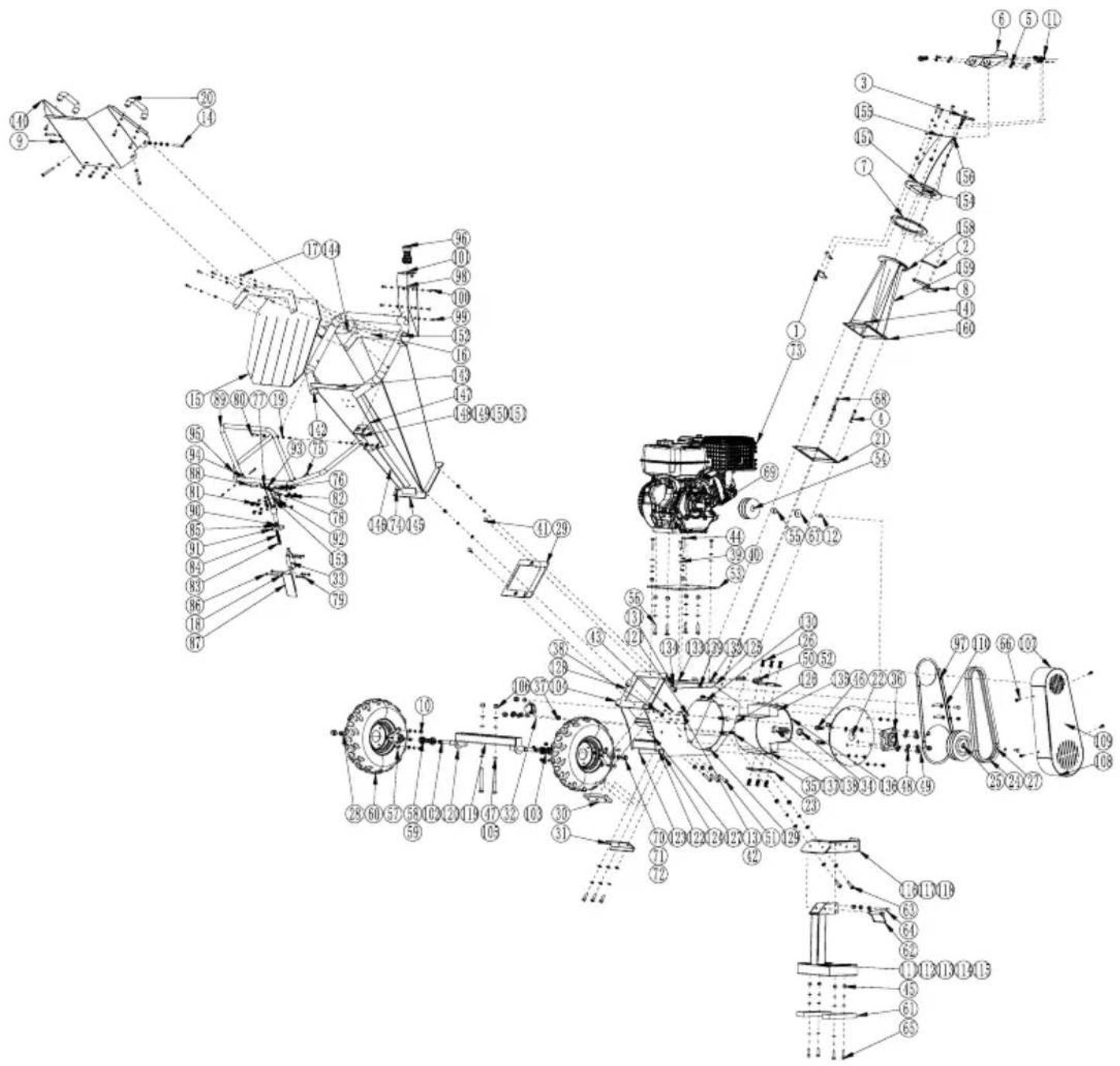
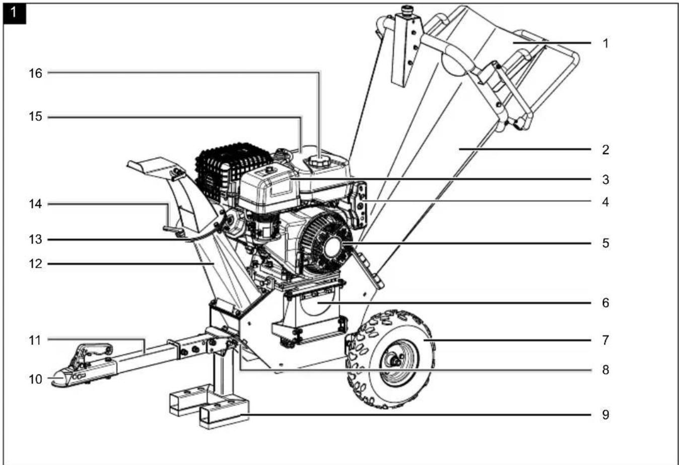
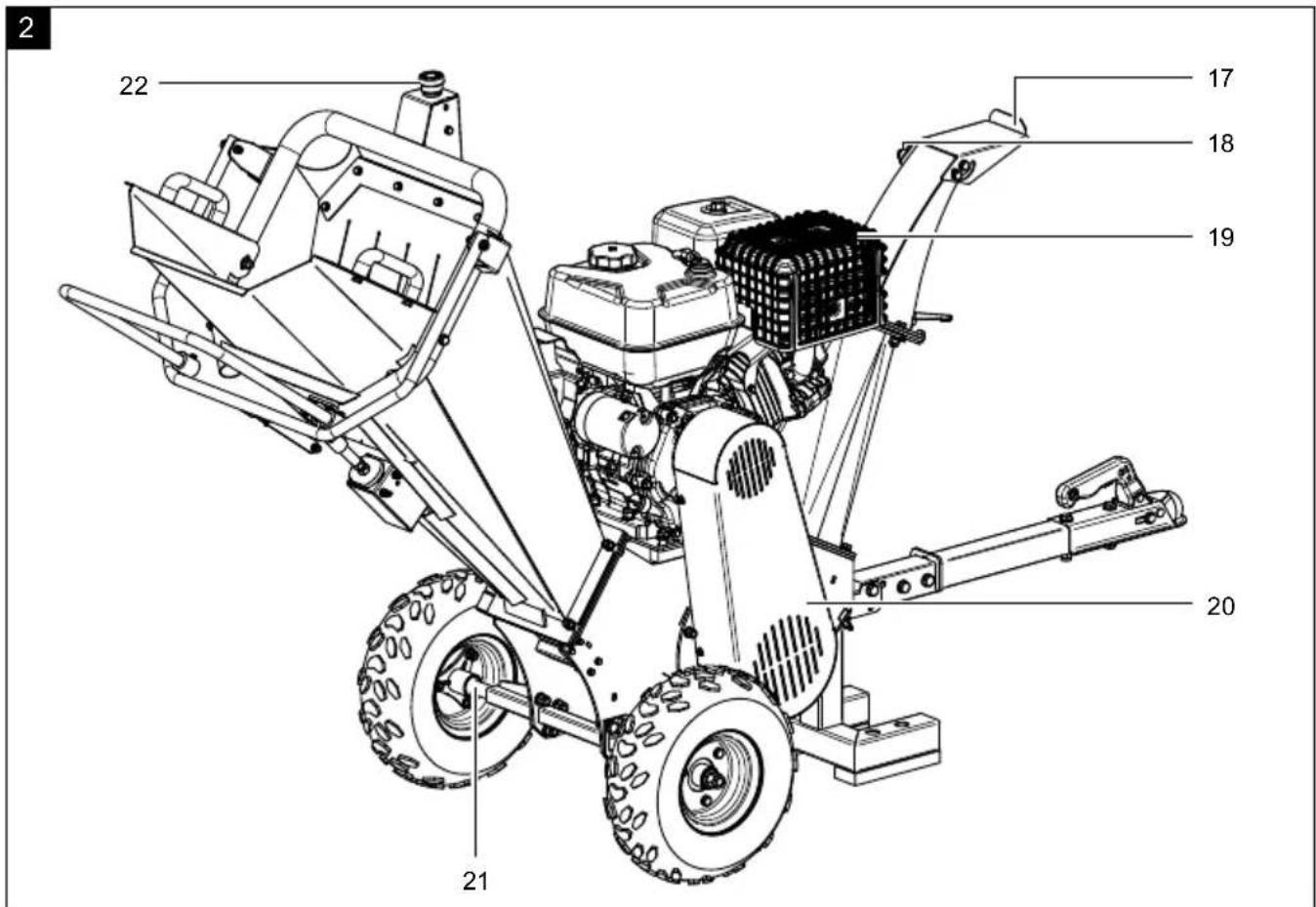
2. Product description (Fig. 1 - 27)
- Filling hopper upper section
- Filling funnel
- Air filter cover
- Operating element (model-dependent)
- Engine
5a. Engine connection cable - Battery (model-dependent)
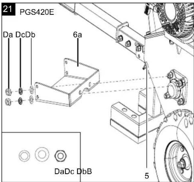
6a. Battery carrier
6b. Battery holder
6c. Battery retaining plate
6d. Battery retaining rubber - Wheels
- Foot bracket
- Foot
- Ball mount (model-dependent)
- Drawbar (model-dependent)
- Ejector chamber
12a. Rubber seal - Live ring
- Live ring quick clamp
-
Fuel tank
-
Fuel filler cap
- Ejector deflector
- Ejector deflector quick release fastener
- Exhaust system
- V-belt cover
- Wheel axle
- EMERGENCY STOP switch
22a. Safety connection cable - Oil dipstick
- Fuel filter insert
- Oil drain screw
- Grease nipple
- Exhaust guard
- Wing screw
- Air filter
- Pull starter
- Fuel valve
- Choke lever
- Throttle
- V-belt
- Spark plug connector
- Spark plug
- On/off switch (model-dependent)
- Handle (safety bar)
38a. Safety bar
A. Spark plug wrench
B. Hexagonal bolts M4 (size 8 mm)
Ba. Self-locking nut M4 (size 8 mm)
Bb. Washer M4
Bc. Spring washer M4
C. Hexagonal bolt M6 (size 10 mm)
Ca. Self-locking nut M6 (size 10 mm)
Cb. Washer M6
Cc. Spring washer M6
D. Hexagonal bolt M8 (size 13 mm)
Da. Self-locking nut M8 (size 13 mm)
Db. Washer M8
Dc. Spring washer M8
E. Hexagonal bolt M10 (size 16 mm)
Ea. Self-locking nut M10 (size 17 mm)
Eb. Washer M10
Ec. Spring washer M10
F. Hexagonal bolt M12 (size 18 mm)
Fa. Self-locking nut M12 (size 18 mm)
Fb. Washer M12
Fc. Spring washer M12
G. Hexagonal bolt M14 (size 21 mm)
Ga. Self-locking nut M14 (size 21 mm)
Gb. Washer M14
Gc. Spacer sleeve
H. Fitting screw with collar M8 (4 mm hexagon socket)
I. Installation spanner
J. T-handle wrench
K. Locking pin
L. Ignition key (model-dependent)
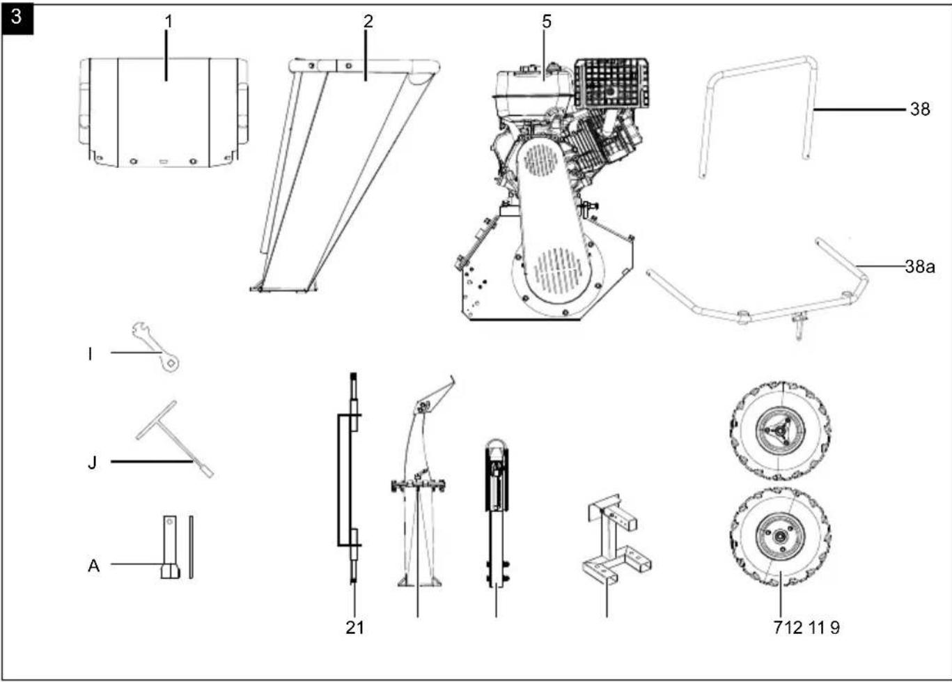
3. Scope of delivery (partially pre-assembled)
Item Quantity Designation
| 1 1x Filling hopper upper section | |
| 2 1x Filling funnel | |
| 5 1x Engine | |
| 7 2x Wheel | |
| 9 1x Foot | |
| 11 1x Drawbar | |
| 12 | 1x Ejector chamber |
| 12 a | 1x Rubber seal |
| 21 | 2x Wheel axle |
| 38 | 1x Handle (safety bar) |
| 38 a | 1x Safety bar |
| A | 1x Spark plug wrench |
| I | 1x Installation spanner |
| J | 1x T-handle wrench |
| L 2x Ignition key | |
4. Proper use
⚠ WARNING
Important safety information – Not approved for road use!
This product is intended exclusively for commercial use on private property, agricultural or forestry land, and construction sites.
The shredder is not approved in accordance with the Road Traffic Licensing Regulations (StVZO) and may not be moved or operated on public roads, paths or squares.
Transport may only be carried out using suitable, approved vehicles and means of transport. Use of the integrated towing system is only permitted on non-public land. The manufacturer accepts no liability for damage, fines or accidents resulting from a breach of these provisions.
Note: Before each start-up, the locally applicable safety and accident prevention regulations must be observed. Only trained personnel may operate or move the product.
The product is suitable for private use in private gardens and allotments. A product for private gardens and allotments refers to a device with an annual operating time generally not exceeding 50 hours, during which time the device is primarily used to shred organic household and garden waste. Public facilities, sporting halls, and agricultural/forestry applications are excluded.
The product may only be used in the intended manner. Any use beyond this is improper. The user, not the manufacturer, is responsible for damages or injuries of any type resulting from this.
An element of the intended use is also the observance of the safety instructions, as well as the assembly instructions and operating information in the operating manual.
Persons who operate and maintain the product must be familiar with the manual and must be informed about potential dangers.
The liability of the manufacturer and resulting damages are excluded in the event of modifications of the product.
The product may only be operated with original parts and original accessories from the manufacturer.
The safety, operating and maintenance specifications of the manufacturer, as well as the dimensions specified in the technical data, must be observed. Proper use includes the shredding of:
- All types of branches up to a maximum diameter of 120 mm (depending on the type of wood and freshness),
• Hedges and tree cuttings, - Shrubs and bushes,
- Wilting, moist, garden waste that has already been stored for several days, alternating with branches.
Please note that our products were not designed with the intention of use for commercial or industrial purposes. We assume no guarantee if the product is used in commercial or industrial applications, or for equivalent work.
The liability of the manufacturer and resulting damages are excluded in the event of modifications of the product.
5. Safety instructions
WARNING
Read all safety warnings, instructions, illustrations and specifications provided with this power tool.
Failure to follow all instructions listed below may result in electric shock, fire and/or serious injury.
Save all warnings and instructions for future reference.
WARNING
The electric ignition system of the product generates a low electromagnetic field. If you wear a pacemaker or similar implant, consult your doctor before using the product, in order to avoid health risks.
Who is not permitted to use the product:
- The product may only be operated by people who are familiar with handling it.
• Children and other people who do are not familiar with the usage instructions (local stipulations may specify a minimum age for users).
• People under the influence of alcohol, drugs and medication, as well as those who are tired or ill.
ATTENTION
Always check whether the filling hopper is empty and that the blades are not blocked prior to starting the engine!
ATTENTION
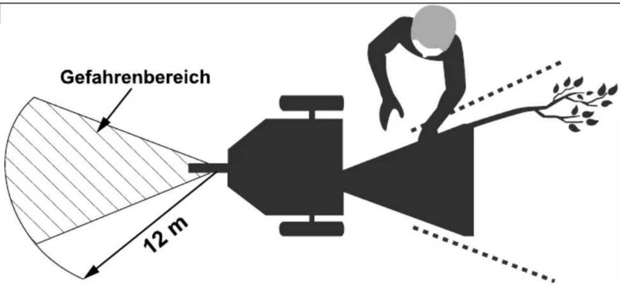
Remaining in the petrol impact garden shredder's danger area when starting and operating is prohibited.
- Never shred while people, especially children or animals are nearby.
- Do not run the combustion engine in closed rooms in which hazardous carbon monoxide can collect.
- Wear hearing protection and safety goggles during the entire operating period.
- Do not wear loose-fitting clothing or clothing with hanging belts or cords.
- Only use the machine outdoors (i.e. not close to a wall or another rigid object) and on a solid, level surface.
- Do not use the machine on a surface paved with gravel where ejected material could cause injuries.
- Ensure that all nuts, pins and screws are securely tightened so that the product is in a safe working
condition.
- Prior to commissioning, all covers and safety devices must be mounted correctly. Damaged or illegible stickers must be replaced. Warning!
5.1 Handling fuels
DANGER
Risk of fire and explosion!
When filling, fuel may ignite and even explode. This can lead to severe burns or death.
- Only store fuel in containers (canisters) designed for this purpose.
- The tank caps must always be properly screwed on and tightened.
- Fuel must be filled before starting the engine. While the engine is running or immediately after switching off the product, do not open the fuel filler cap or add fuel.
- Before refuelling, switch off the combustion engine and let it cool down.
- Refuel outdoors only and do not smoke while refuelling.
- Never store the product with fuel in the tank inside a building. Any fuel vapours produced can come into contact with naked flames or sparks and ignite.
- Do not place the product and fuel tank near heaters, radiant heaters, welding products or other sources of heat.
- If fuel has overflowed, do not start the combustion engine until the area contaminated with fuel has been cleaned. Avoid starting the engine until the fuel vapours have evaporated (wipe dry).
- For safety reasons, check fuel line, fuel tank, fuel cap and connections regularly for damage, ageing (brittleness), tight fit and leaks and replace if necessary.
- Make sure that all nuts, bolts and screws are securely tightened so that the product is kept in a safe working condition.
- Never store the product with petrol in the tank inside a building in which fuel vapours may come into contact with naked flames or sparks.
- Allow the engine to cool down before parking the product in enclosed spaces.
- In order to avoid fire hazards, keep the engine, exhaust system and the area around the fuel tank free of grass, leaves and leaking grease (oil).
5.2 Handling
- Check the product for signs of wear and loss of functionality.
- For safety reasons, replace worn or damaged parts.
- If the fuel tank has to be drained, you must do this outdoors.
- Do not run the combustion engine in closed rooms in which hazardous carbon monoxide can collect.
- Only shred in daylight or with good artificial lighting.
- Do not use the product in a thunderstorm - Danger of lightning strike!
• Always maintain good footing on inclines.
- All protective devices and covers must be installed before any work is carried out on the machine.
- Never use the product if the blade or safety grilles are damaged, or without the attached guards, e.g. deflectors and/or ejector deflector.
- Do not adjust and overclock the engine speed settings.
- Start the engine with care, in accordance with the manufacturers instructions.
- The product must not be tipped when starting the engine.
- Do not start the engine if you are standing in front of the ejector chamber.
- Never put hands and feet on or under rotating parts. Always keep clear of the ejector chamber.
- Never reach into the filler or ejection opening. The product interior contains moving parts that could possibly pull you into the machine.
- Never lift or transport the product with the engine running.
- Only carry out maintenance work and rectify faults when the engine is switched off.
- Stop the engine and make sure that all moving parts have come to a standstill and that the ignition key, if present, is removed:
- Before you dislodge any blockages or clogs in the ejector chute.
- Before checking or cleaning the product, or performing work on it.
- If the product begins to experience exceptionally strong vibrations, switch it off immediately and check it.
- Any time you leave the product.
- Before you refuel.
- Close the fuel valve after shredding.
- Operating the product at excessive speed can increase the risk of accidents.
- Be careful when adjusting the product and avoid trapping fingers between the moving blade and rigid parts of the product.
- Avoid shredding in places where the wheels have trouble gripping or shredding is unsafe in any other way.
• Watch out for traffic near a road.
- The user must be adequately trained in the use, adjustment and operation of the machine (including prohibited operations).
- Check the product regularly and make sure that all start locks and push buttons are working properly before each use.
- Please note that improper maintenance, the use of non-compliant spare parts, or the removal or modification of safety devices can result in damage to the product and serious injury to the person working with it.
- When the emergency stop switch or safety bar is pressed, the product must shut down immediately and must not start up. If this does not happen as described, do not operate the product under any circumstances and contact our service department.
- Please note that the product's safety systems or equipment must not be tampered with or deactivated. Never remove any safety-related parts.
- Please note that the user must not change or manipulate any sealed engine speed control settings.
- Use only blades and accessories recommended by the manufacturer. Use of other insert tools and accessories may result in injury to the user.
• Always keep the product in good operating condition
- It is necessary to take enough breaks to reduce noise and vibration exposure.
- The protective clothing and all accessories used must correspond to the "Personal Protective Equipment" directive.
- Only wear closed, suitable clothing and protective gloves with short, closed, sealing cuffs.
ATTENTION: Use only E5 unleaded petrol as fuel. ⚠️ Use of petrol
⚠ Danger to life! Petrol is toxic and highly flammable.
- Only store petrol in containers (canisters) designed and tested for this purpose. The fuel tank caps must always be properly screwed on and tightened. Defective caps must be replaced for safety reasons.
- Keep petrol away from sparks, open flames, permanent flames, heat sources and other sources of ignition. Do not smoke!
- Refuel outdoors only and do not smoke while refuelling.
- Before refuelling, switch off the combustion engine and let it cool down.
- Petrol must be filled before starting the combustion engine. While the combustion engine is running or if the product is hot, the fuel tank must not be opened and petrol must not be filled.
- Open the fuel filler cap carefully and slowly. Wait for the pressure to equalise and only then remove the fuel filler cap completely.
- Use a suitable funnel or filler pipe for refuelling so that no fuel can spill onto the combustion engine and housing or lawn.
Do not overfill the fuel tank!
• To leave room for the fuel to expand, never fill the fuel tank beyond the lower edge of the filling nozzle. Observe additional information in the combustion engine user manual.
- If petrol has overflowed, do not start the combustion engine until the petrol-contaminated area has been cleaned. Avoid starting the engine until the petrol vapours have evaporated (wipe dry).
• Always wipe up spilled fuel immediately.
• If petrol has got on clothing, it must be changed.
- The tank cover must be properly screwed on and tightened after each refuelling operation. The product must not be put into operation without the original tank cover screwed on.
- For safety reasons, check the fuel line, fuel tank, fuel filler cap and connections regularly for damage, ageing (brittleness), tight fit and leaks, and replace if necessary.
- Only empty the fuel tank outdoors.
- Never use beverage bottles or similar to dispose of or store operating materials such as fuel. People, especially children, could be tempted to drink from it.
- Only use the product outdoors and never in closed or poorly ventilated rooms.
- Never store the product with petrol in the fuel tank inside a building. Any petrol vapours produced can come into contact with naked flames or sparks and ignite.
- Do not place the product and fuel tank near heaters, radiant heaters, welding machines or other sources of heat.
Risk of explosion!
If a defect is detected on the fuel tank, the fuel filler cap or on fuel-carrying parts (fuel lines) during operation, the combustion engine must be switched off immediately. Then consult a specialist dealer.
Battery safety
- To avoid spark formation due to a short circuit, always disconnect the negative cable (-) from the battery first and reconnect it last.
- Never smoke during any work on the battery. Always keep sparks, naked flames and other heat sources away from the battery.
- Special care must be taken when using jumper cables. Follow relevant instructions to avoid damage to the product (in particular, do not operate the starter for more than 10 seconds).
- Never open the battery and do not drop it.
• Always charge the battery in a closed room with good ventilation, dry and protected against the weather. - Do not short-circuit battery connections.
- Deformed or defective (leaking) batteries must not be used and must be replaced and disposed of in an environmentally friendly manner. Observe the country-specific regulations.
- If the batteries are defective, liquid may leak out. Avoid contact! If contact accidentally occurs, flush with water. If the liquid gets into your eyes, seek additional medical attention. Leaking battery fluid can cause skin irritation, burns and chemical burns.
- Regularly visually inspect the connection cables on the battery for damage. Have damaged cables replaced by a specialist.
- Never bypass the fuses. Never use a fuse with a rating other than the prescribed rating (amperes).
5.3 Residual risks
The product has been built according to state-of-the-art and the recognised technical safety rules.
However, individual residual risks can arise during operation.
- Residual risks can be minimised if the "Safety Instructions" and the "Intended Use" together with the operating instructions as a whole are observed.
- Use the product in the way that is recommended in this operating manual. This is how to ensure that your product provides optimum performance.
- Prevent the product being unintentionally started up.
- Keep your hands away from the working area when the product is in operation.
- Comply with the stipulated maintenance and safety instructions in the operating instructions.
• Furthermore, despite all precautions having been met, some non-obvious residual risks may still remain.
6. Technical data
| Dimensions L x W x H 2200 x 700 x 1110 mm | |
| Infeed height 1050 mm | |
| Infeed opening max. 460 x 380 mm | |
| Wheel ø 360 mm | |
| Weight fully assembled and without fuel | 142 kg |
| Branch thickness max ø 120 mm | |
| Number of blades 3 | |
| Blade 150 x 55 x 5 mm | |
| Type of engine | 4-stroke, 1 cylinder, air-cooled |
| Displacement | 420 cm3 |
| Rotation speed | 3600 rpm |
| Power | 9 kW / 12.2 PS |
| Fuel | Unleaded, min. 95 ROZ (RON), max. 10 % Bioethanol (E10) |
| Tank contents | 6.5 l |
| Engine oil | SAE 10W-30 |
| Oil tank capacity | 1.1 l |
| CO2 output | 777.93 g/kWh |
| Spark plug | F7RTC |
| Tyre pressure | 0.7 bar |
| Battery type (model-dependent) | Lead acid battery |
| Battery rated voltage (model-dependent) | 12 V |
| Battery capacity (model-dependent) | 18 Ah |
Subject to technical changes!
Noise and vibration
⚠ WARNING
Noise can have serious effects on your health. If the machine noise exceeds 85 dB, please wear suitable hearing protection for you and persons in the vicinity.
Information about noise level measured in accordance with applicable standards
Noise data
| Measured sound power level L_WA | 109.3 dB |
| Uncertainty K_WA | 2.66 dB |
| Sound pressure level L_pA | 99.2 dB |
| Uncertainty K_pA | 3 dB |
Wear hearing protection.
Exposure to noise can cause hearing loss.
7. Unpacking
⚠ WARNING
The product and the packaging material are not children's toys! Do not let children play with plastic bags, films or small parts! There is a danger of choking or suffocating!
- Open the packaging and carefully remove the product.
- Remove the packaging material, as well as the packaging and transport safety devices.
- Check whether the scope of delivery is complete.
- Check the product and accessory parts for transport damage. In the event of complaints the carrier must be informed immediately. Later claims will not be recognised.
- If possible, keep the packaging until the expiry of the warranty period.
- Familiarise yourself with the product by means of the operating manual before using for the first time.
- With accessories as well as wearing parts and replacement parts use only original parts. Spare parts can be obtained from your specialist dealer.
- When ordering please provide our article number as well as type and year of manufacture for the product.
8. Assembly
ATTENTION
Always make sure the product is fully assembled before commissioning!
ATTENTION
Due to the heavy product weight, we recommend that at least three people assemble the product.
Place the product on a level, even surface.
Ensure that the safety switch and cable are not broken or damaged by being crushed, pulled or the like.
Required tool
- 1x pad*
- 1x wooden block *
- 1x 4mm Allen key *
- 1x open-ended/ratchet spanner size 8 mm *
- 1x open-ended/ratchet spanner size 10 mm *
- 1x open-ended/ratchet spanner size 13 mm *
- 1x open-ended/ratchet spanner size 16 mm *
- 1x open-ended/ratchet spanner size 18 mm *
- 1x open-ended/ratchet spanner size 21 mm *
* = may not be included in the scope of delivery!
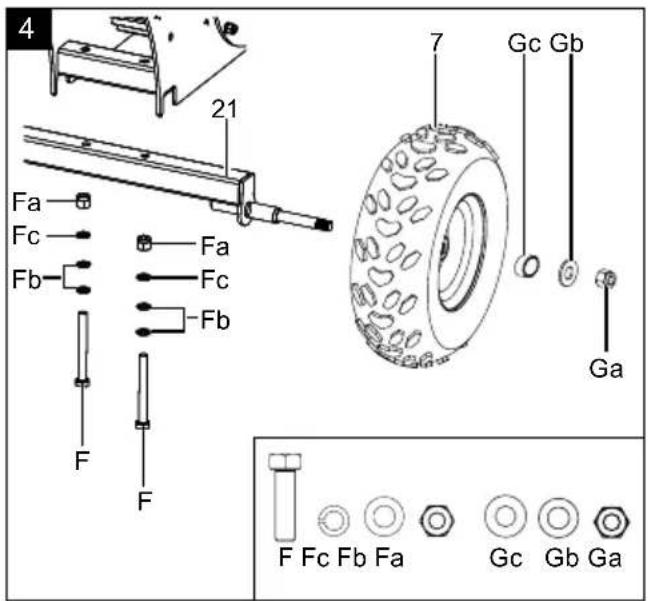
8.1 Fitting the wheels (7) and wheel axle (21) (Fig. 4)
- Place a pad on the floor to avoid damage to the product.
- Carefully remove the product from the pallet with two other people.
- Tilt the shredding unit forward slightly.
- First, fit the wheel axle (21) as shown in Fig. 4. Ensure that the wheel axle (21) is correctly seated.
- Now fit the wheels (7) by first removing the self-locking nut (Ga), washers (Gb) and spacer sleeve (Gc) from the wheel axle (21). Now place the wheels (7) on the wheel axle (21). Then place the spacer sleeve (Gc) and washer (Gb) on the wheel axle (21) and secure them with the self-locking nut (Ga). These are already attached to the wheel axle (21) upon delivery. Use a size 21 mm open-ended/ratchet spanner * to fit the self-locking nut (Ga).
NOTE! Please observe the above sequence during installation. Failure to comply may result in damage to the bearing in the wheel.
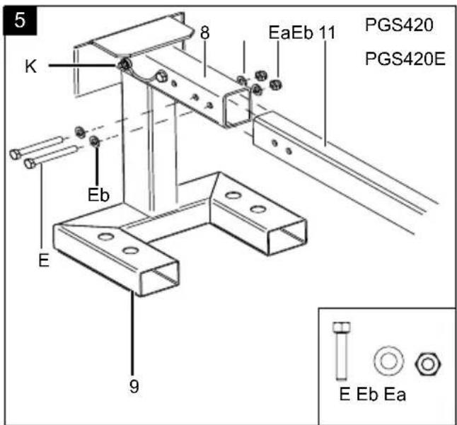
8.2 Fitting the drawbar (11) and the foot (9) (Fig. 5) (model-dependent)
- First, remove the hexagonal bolts (E) pre-mounted in the drawbar (11), including washers (Eb), spring washers (Ec) and self-locking nuts (Ea). Use a size 16 mm open-ended/ratchet spanner for disassembly.
- Connect the drawbar (11) to the foot bracket (8) by pushing the drawbar (11) into the foot bracket recess (8) until the fitting holes are aligned.
- Secure the drawbar (11) to the foot bracket (8) using two hexagonal bolts (E), washers (Eb), spring washers (Ec) and self-locking nuts (Ea). Use a 16 mm open-ended/ratchet spanner for assembly.
- Fold out the foot (9) and secure it with the locking pin (K). Now place the product on the foot (9).
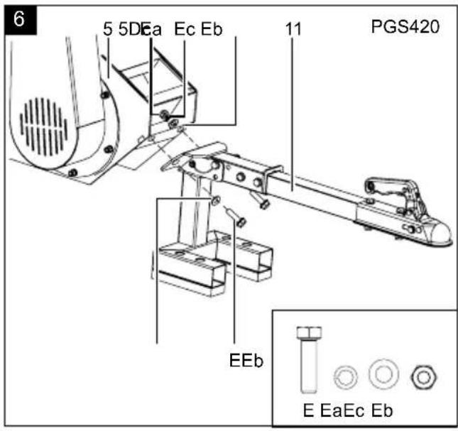
8.3 Fitting the drawbar (11) including foot on the engine (5) (Fig. 6) (model-dependent)
- Place a wooden block under the ejector chamber (12) to raise the motor (5) to the desired working height of the drawbar (11).
- Remove the pre-assembled hexagonal bolts (E) including washers (Eb), spring washers (Ec) and self-locking nuts (Ea) from the motor (5). Use a size 16 mm open-ended/ratchet spanner for disassembly.
- Now lift the drawbar (11) with the foot (9) unfolded and secured into the designated position (below the ejector chamber (12)).
- Secure the drawbar (11) to the motor (5) using two hexagonal bolts (E), washers (Eb), spring washers (Ec) and self-locking nuts (Ea). Use a 16 mm open-ended/ratchet spanner for assembly.
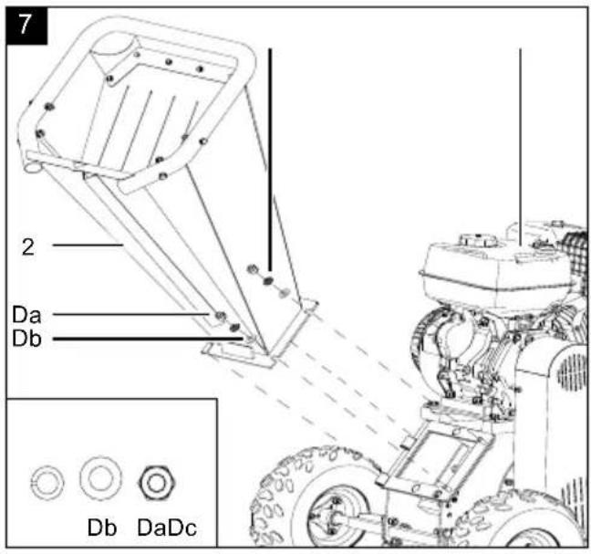
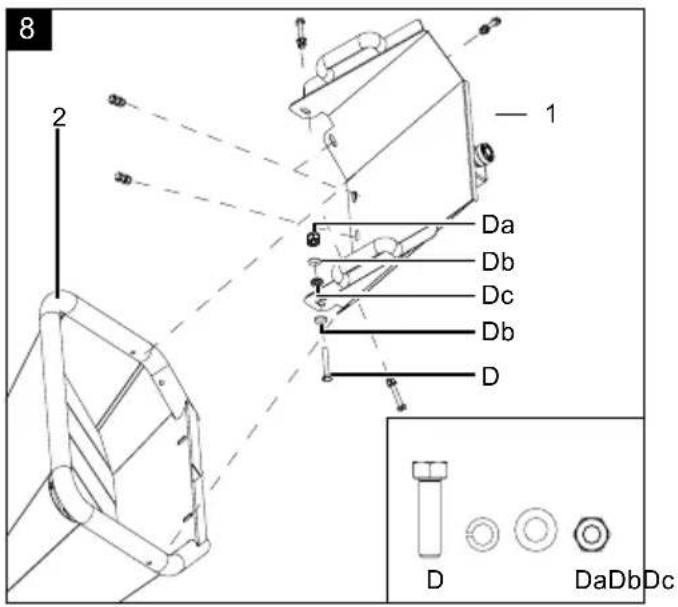
8.4 Assembling the filling hopper (2) and filling hopper upper section (1) (Fig. 7-9)
- First, remove all pre-assembled hexagonal bolts (D) including washers (Db), spring washers (Dc) and self-locking nuts (Da) from the motor inlet (5) and upper part of the filling hopper (1). Use a size 13 mm open-ended/ratchet spanner for disassembly.
- Position the filling hopper (2) over the hinge on the diesel engine's filling chute (5) and join them together.
- Screw the filling hopper (2) to the shredding unit using two washers (Db), two spring lock washers (Dc) and two self-locking nuts (Da). Use a size 13 mm open-ended/ratchet spanner to perform the assembly of the self-locking nuts (Da).
- Now place the upper part of the filling hopper (1) onto the filling hopper (2) and secure it with the hexagonal bolts (D), spring washers (Dc), washers (Db) and self-locking nuts (Da) that were removed at the beginning.
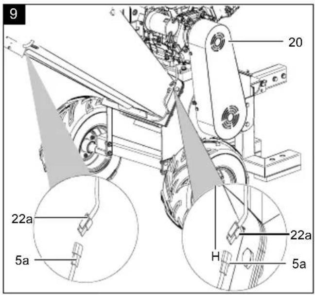
- To activate the EMERGENCY STOP switch (22), connect the safety connection cable (22a) of the EMERGENCY STOP switch (22) to the engine connection cable (5a) at the lower part of the filling hopper (2) and at the top section of the filling hopper (1) (Fig. 9).
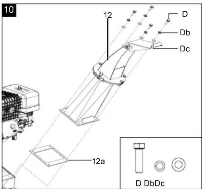
8.5 Fitting the ejector chamber (12) (Fig. 10)
-
First, remove all pre-assembled hexagonal bolts (D), including washers (Db) and spring washers (Dc), from the motor ejector (5). Use a size 13 mm open-ended/ratchet spanner for disassembly.
-
Position the ejector chamber (12) with the rubber seal (12a) over the shredding unit and ensure that the fitting holes are aligned.
- Screw the ejector chamber (12) to the shredding unit using the hexagon screws (D), spring washers (Dc) and washers (Db). Use a 13 mm open-end/ratchet spanner to fit the hexagonal bolts (D).
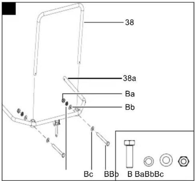
8.6 Fitting the safety bar (38/38a) (Fig. 13)
- First, remove all pre-fitted hexagonal bolts (B) including washers (Bb), spring washers (Bc) and self-locking nuts (Ba) from the safety bar (38a). Use a size 8 mm open-ended/ratchet spanner for disassembly
- Insert the ends of the handle (38) into the sockets of the safety bar (38a).
- Now fit all the hexagonal bolts (B) that were removed at the start, including washers (Bb), spring washers (Bc) and self-locking nuts (Ba) on the safety bar (38a). Use a size 8 mm open-ended/ratchet spanner for assembly
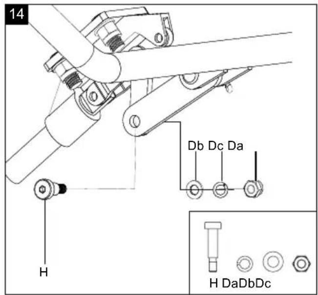
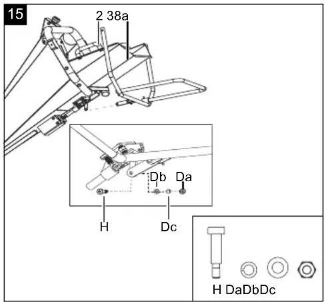
8.7 Fitting the safety bar (38a) with the release mechanism (Fig. 14, 15)
- Align the hole on the joint of the safety bar (38a) with the joint on the release mechanism.
- Fit the connection using the M8 collar screw (H), the washer (Db), the spring lock washer (Dc) and the self-locking nut (Da). Use a 4 mm Allen key and a 13 mm open-ended spanner.
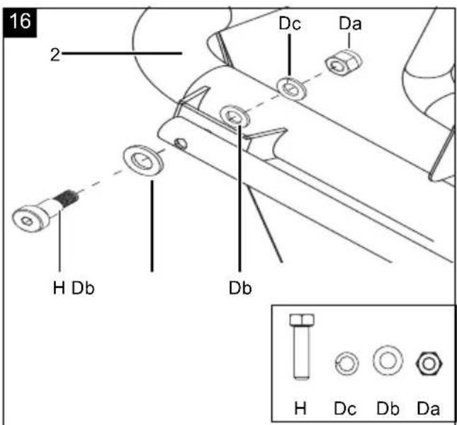
8.8 Fitting the safety bar (38a) to the filling hopper (2) (Fig. 16)
- Align one end of the safety bar (38a) with the mounting bar of the filling hopper (2).
- Fit the connection using the M8 collar screw (H), the washer (Db), the spring lock washer (Dc) and the self-locking nut (Da). Use a 4 mm Allen key and a 13 mm open-ended spanner.
- Repeat the process on the other side.
ATTENTION
Danger of short circuit!
- To avoid a short circuit, always disconnect the negative cable (-) from the battery first and reconnect it last.
- When connecting/disconnecting the battery (6), ensure that the poles (+/-) do not touch each other and/or the frame.
9. Before commissioning
ATTENTION
Always make sure the product is fully assembled before commissioning!
⚠ WARNING
Before each start-up, ensure that all safety devices are functioning properly.
⚠ WARNING
Health hazard!
Inhalation of fuel / lubricating oil vapours and exhaust gases can cause serious damage to health, unconsciousness and in extreme cases death.
- Do not breathe fuel / lubricating oil vapours and exhaust gases.
- Operate the product outdoors only.
ATTENTION
Product damage!
Using the product without or with too little engine and gear oil can result in engine damage.
- Fill with fuel and oil before commissioning. The product is supplied without engine and gearbox oil.
ATTENTION
Environmental damage!
Spilled oil can pollute the environment permanently. The liquid is highly toxic and can quickly lead to water pollution.
- Fill/empty oil only on level, paved surfaces.
- Use a filling nozzle or funnel.
- Collect drained oil in a suitable container.
- Wipe up spilled oil carefully immediately and dispose of the cloth according to local regulations.
- Dispose of oil as per local regulations.
ATTENTION
Risk of damage!
If incorrectly stored or undrained fuel is used, the carburettor may become clogged or engine operation may be affected.
- Put unused fuel in an airtight vessel and store it in a dark, cool room.
Place the product on a level, even surface. Required tool:
- Funnel*
- Rag/cloth*
* = may not be included in the scope of delivery!
9.1 Topping up oil (Fig. 14)
ATTENTION
The product is delivered without engine oil. Therefore, ensure that you add oil before starting it up. Use SAE 10W-30 oil.
Check the oil level regularly before commissioning. An oil level that is too low can damage the motor.
- Unscrew the oil dipstick (23).
- Fill the engine oil tank using a funnel. Do not exceed the maximum filling level (see Technical Data). Carefully fill the engine oil to the lower edge of the filling nozzle.
- Wipe the oil dipstick (23) with a clean, lint-free cloth.
- Screw the oil dipstick (23) back into the filler neck until it reaches the stop.
- Screw the oil dipstick (23) out and read the oil level in the horizontal position. The oil level must be in the middle on the oil dipstick (23).
- If the oil level is too low, repeat the process.
- Then screw the oil dipstick (23) in again.
9.2 Connecting the battery (model-dependent)
- Before starting, remove the cover from the two connections
- First, connect the red cable to the positive terminal (+). Ensure that the terminal is clean and the clamp is securely fastened. Tighten the screw connection.
- Then make the connection between the black cable and the negative terminal (-) and tighten it as well.
- Please note the order!
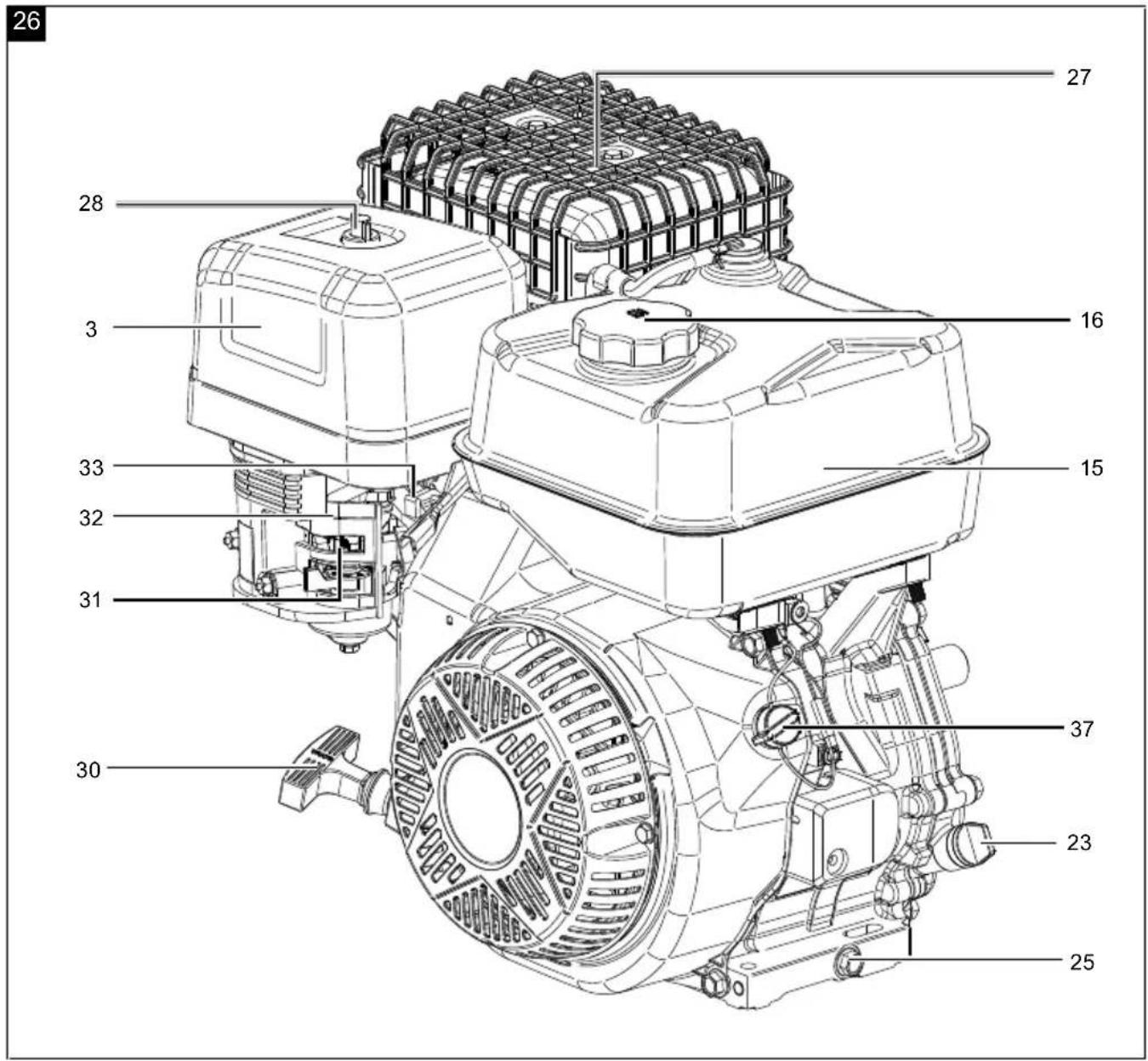
9.3 Filling with fuel (Fig.26)
- Unscrew the fuel filler cap (16).
- Use a suitable funnel to fill petrol into the fuel tank (15). Do not exceed the maximum filling level (see Technical Data).
- Ensure that the fuel tank (15) is not overfilled and that no fuel is spilled. Wipe up spilled fuel immediately and wait until the fuel vapours have evaporated (risk of ignition!).
- Retighten the fuel filler cap (16).
10. Operation
ATTENTION
Attention!
When using products, several safety warnings must be observed to prevent injuries and damage. For this reason, please carefully read this operating manual/ these safety instructions.
If you hand the product over to another person, please hand over this operating manual / safety instructions as well. We accept no liability for accidents or damage that occur due to a failure to observe this manual and the safety instructions.
ATTENTION
Always make sure the product is fully assembled before commissioning!
ATTENTION
Always check whether the filling hopper is empty and that the blades are not blocked prior to starting the engine!
ATTENTION
Before shredding, always check that the emergency stop bracket and the emergency stop switch switch off correctly.
ATTENTION
Remaining in the petrol impact garden shredder's danger area when starting and operating is prohibited.
⚠ WARNING
Check the safety equipment regularly before each start-up. Faulty safety equipment can cause serious injuries!
Working instructions
Good work results require well sharpened blades.
Note:
Blunt blades reduce the cutting performance and impair the work process! Sure signs of blunt blades are leaving an indentation, reduced performance and a poor cutting pattern.
Feeding the chopped material
Always switch the engine off first!
- Only wear closed, suitable clothing and protective gloves with short, closed, sealing cuffs.
• Always stand to the side of the filling funnel when feeding chopped material (Fig. 23).
- Mark out an area at least 3 m wide and 12 m long on the side of the ejector. Check the immediate vicinity before starting. Pay particular attention to children, other people and animals (Fig. 23).
• Make sure that you have secure footing and always maintain your balance. Do not lean forwards.
- Stand at the same level as the product when inserting the chopped material.
- Stay a safe distance from the ejector area in order to avoid being hit by chopped material or parts being ejected.
- Pay attention to stones and soil when collecting the material to be cut.
- Earth causes the blades to wear very quickly and should therefore be removed from the material to be shredded.
- Foreign objects (such as nails, wire, ropes or climbing aids) must be removed from the material to be shredded.
- Hard objects such as stones, glass, metal and similar objects must not be thrown into the product.
- Do not throw roots with soil attached to them into the product.
- Wood such as tree cuttings, etc. requires well sharpened blades and should be crushed separately to maintain as long a service life as possible for the blades.
- The cutting unit draws the chopped material in virtually automatically.
- Insert branches with the thickest end first and place on the part of the cutter disc that rotates downwards if possible (kick-back).
- Remove side shoots from branches with many smaller branches.
- Freshly-cut wood requires less force meaning that sections with larger cross sections can be shredded.
- Processing dry material at the end is beneficial. The moisture in the product is absorbed and the housing cleaned.
- If the cutting unit gets blocked, switch the engine off immediately to avoid an engine overload. Rectify the fault before switching the engine back on.
- Do not let the pile of shredded material in the vicinity of the ejection opening get too high. This can result in shredded material blocking the ejector chute.
This can cause the material to kick-back through the filling opening.
Note: Remove residual waste from the product after finishing work.
ATTENTION
Pull the spark plug connector and the ignition key out! The shredding unit must be free of shredded material residues in order to restart it after work breaks.
Speeds
Use the throttle lever (33) to set the engine to the desired speed.
• MIN position - "tortoise"
• MAX position - "hare"
Note:
Depending on the model, the engine (5) can be started using the electric starter or the pull starter (30).
10.1 Switching the product on/off
ATTENTION
- Always pull the pull starter out straight.
- Hold the handle of the pull starter firmly when the pull starter winds back in.
- Do not let the pull starter whip back in. This can result in damage.
- Do not pull the pull starter out to its full length. This prevents the starter cable breaking.
- In case of cool weather, it may be necessary to repeat the starting process numerous times
10.1.1 Start the engine (5) with the pull starter (30) (model-dependent)
ATTENTION
Never allow the pull starter (30) to whip back. This can result in damage.
- Set both the choke lever (32) and the fuel valve (31) on the engine to "ON".
- Position the throttle (33) in the middle.
- Insert the ignition key (L) into the ignition lock.
- Turn the ignition key (L) to the middle position, "Switch on".
- Now pull the pull starter (30) slowly several times so that fuel can flow from the fuel tank (15) to the engine (5).
- Start the engine (5) by pulling the pull starter (30) quickly. If the engine (5) does not start, repeat the
process.
- Let the engine (5) warm up for several seconds.
- Turn the choke lever (32) to the "OFF" position slowly.
- Use the throttle to set the required speed (33).
- If the engine (5) does not start even after several attempts, read the "Troubleshooting" chapter.
- The choke is not normally required when restarting a warm engine.
10.1.2 Starting the engine (5) with the electric starter (model-dependent)
- Set both the choke lever (32) and the fuel valve (31) on the engine (5) to "ON".
- Position the throttle (33) in the middle.
- Insert the ignition key (L) into the ignition lock.
- Turn the ignition key (L) to the right position, "E-starter" and hold it in this position until the product starts up.
- Let the engine (5) warm up for several seconds.
- Turn the choke lever (32) to the "OFF" position slowly.
- Use the throttle to set the required speed (33).
- If the engine (5) does not start even after several attempts, start the product as described in section 10.1.1.
- The choke is not normally required when restarting a warm engine.
10.1.3 Starting with a cold engine using a pull starter (without electric start)
Note:
With high outside temperatures, it may be necessary to start the engine without the choke even when the engine is cold!
- Before starting, check the fuel and engine oil levels and ensure that the spark plug connector (35) is connected to the spark plug (36).
- Set the on/off switch (37) to the "ON" position.
- Set the throttle (33) to "half throttle" (= middle position between "fast" and "slow").
- Move the choke lever (32) to the "Closed" position.
- Open the fuel valve (31).
- Slowly pull out the pull starter (30) until the first resistance is felt.
- Now pull the pull starter (30) and the engine should start. If the engine does not start, repeat the process.
-
Allow the engine to warm up briefly. Then slowly open the choke lever (32) to switch to "Normal operation".
-
Use the throttle lever (33) to set the speed that is suitable for you.
10.1.4 Starting with a pull starter when the engine is warm
(The product stood still for less than 15-20 minutes.)
- Before starting, check the fuel and engine oil levels and ensure that the spark plug connector (35) is connected to the spark plug (36).
- Set the on/off switch (37) to the "ON" position.
- Set the throttle (33) to "half throttle" (= middle position between "fast" and "slow").
- Open the fuel valve (31).
- Slowly pull out the pull starter (30) until the first resistance is felt.
- Now pull the pull starter (30) and the engine should start. If the product has still not started after 6 pulls, repeat the process described under 10.1.3.
- Use the throttle lever (33) to set the speed that is suitable for you.
10.1.5 Shutting the engine off
Allow the product to run for a short time (approx.
30 seconds) switching it off so that the engine can cool down.
- Use the throttle (33) to set the speed to MIN-"tortoise".
- Turn the on/off switch (37) to "OFF".
- Close the fuel valve (31).
10.2 Automatic oil cut-off
Note:
The automatic oil cut-off system responds when there is too little engine oil.
- If the oil level is too low, top up the oil as described in 9.1.
- Start the engine (5) as described in 10.1.
Working instructions
ATTENTION
Keep a sufficient distance from the product when shredding, as long branches can kick out when being pulled in. There is a danger of injury.
- Ensure that the catch basket is correctly attached.
- Hold branches when feeding them into the product until they are automatically drawn in.
-
Before shredding, remove roots from attached soil debris and stones.
-
Do not shred soft, moist material such as kitchen waste, but compost it directly.
• Alternate the chopping of wilting garden waste that has been stored for several days with branches in order to prevent clogging. - Allow the shredder to fully shred the shredding material introduced before you introduce any new materials.
- Do not use your hands to push down the chopped material, only use a specialist plug for this or other chopped material.
- Switch off the shredder after the work has been completed and disconnect this from the power supply.
- Save a few dry branches until the end to use them to help clean.
- Do not switch off the product until all the chopped material has passed through the shredder. Otherwise, the blades may jam when restarting.
11. Cleaning and maintenance
WARNING
Have maintenance and repair tasks that are not described in this operating manual, carried out by our specialist workshop. Use only original spare parts .
⚠ WARNING
Improper maintenance or cleaning work can cause injuries!
⚠ WARNING
The product may start unexpectedly and cause injuries and burns during cleaning, repair and maintenance work.
- Switch the product off.
- Remove the spark plug connector from the spark plug.
- Allow the product to cool down.
WARNING
Carry out a visual and functional check/maintenance regularly/daily and before commissioning to ensure that the product is in good operating condition.
- Incorrect maintenance, use of non-conforming replacement parts, or removal or modification of safety equipment may lead to severe property or personal damages.
- If this work cannot be carried out by the user themselves, see a specialist dealer.
11.1 Cleaning
Place the product on a level, even surface.
⚠ WARNING
Never use a high-pressure cleaner to clean your product.
The use of high-pressure cleaners shortens the service life and reduces the ease of maintenance.
⚠ WARNING
Carry out a visual and functional check/maintenance regularly/daily and before commissioning to ensure that the product is in good operating condition.
- Incorrect maintenance, use of non-conforming replacement parts, or removal or modification of safety equipment may lead to severe property or personal damages.
- If this work cannot be carried out by the user themselves, see a specialist dealer.
- Keep protective devices, air vents and the motor housing as free of dust and dirt as possible. Rub the product clean with a clean cloth or blow it off with compressed air at low pressure. We recommend that you clean the product directly after every use.
• Empty the catch basket after each use.
- Clean the product at regular intervals using a damp cloth* and a little soft soap. Do not use any cleaning products or solvents; they could attack the plastic parts of the product. Make sure that no water can penetrate the product interior.
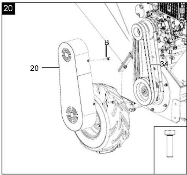
11.1.1 Cleaning the V-belt (34) (Fig.20)
- Place the product on a level, even surface.
- Remove the ignition key (L) (33) from the ignition lock (34) (model-dependent).
- Remove the spark plug connector (35) from the spark plug (36).
- Remove the V-belt cover (20) by unscrewing the four hexagon screws (B) with a size 8 mm open-ended/ratchet spanner.
- Clean the elements of the transmission and the V-belt (34) once or twice a year with a brush or compressed air.
- Re-attach the V-belt cover (20) and secure it with four hexagonal bolts (B).
11.1.2 Removing blockages and shredder residues Switch the machine off to rectify faults or to remove jammed pieces of wood.
- Place the product on a level, even surface.
- Remove the ignition key (L) from the ignition lock (model-dependent).
-
Remove the spark plug connector (35) from the spark plug (36).
-
Disconnect the safety switch connection cable.
-
Disassemble the filling hopper (2) and the ejector chamber (12) and remove the ejector chamber rubber seal (12a). Use a 13 mm open-ended/ratchet spanner to remove the hexagon bolts (D) and the self-locking nuts (Da).
-
In the event of persistent malfunctions, remove the V-belt cover (20) as described in section 11.1.1 and then slowly turn the cutter shaft using the ratchet spanner provided to eliminate the malfunction.
-
Clean inside the product and the cutter disc with compressed air in order to remove shredded material residues.
-
Refit the filling hopper (2) and the ejector chute (12), the rubber seal on the ejector chute (12a) and the V-belt cover (20).
12. Transport
WARNING
Important safety information – Not approved for road use!
This product is intended exclusively for commercial use on private property, agricultural or forestry land, and construction sites.
The shredder is not approved in accordance with the Road Traffic Licensing Regulations (StVZO) and may not be moved or operated on public roads, paths or squares.
Transport may only be carried out using suitable, approved vehicles and means of transport. Use of the integrated towing system is only permitted on non-public land.
The manufacturer accepts no liability for damage, fines or accidents resulting from a breach of these provisions.
12.1 Preparation for transport
- Empty the fuel tank (15) using a petrol extraction pump.
Warning: Do not remove the petrol in enclosed spaces, near fire or when smoking. Petrol fumes can cause explosions and fire.
- The ignition key (L) must always be removed from the ignition lock and stored securely to prevent unauthorised or improper use by children and other persons (model-dependent).
- Remove the spark plug connector (35) from the spark plug (36).
- Clean the product.
12.2 Transporting without a vehicle (model-dependent)
⚠ Attention: When the product is being transported, the engine must be switched off and the spark plug connector removed.
- To move the product, grip the ball holder (10) and tilt the product backwards.
- You can now transport the product.
12.3 Transporting with a vehicle (model-dependent)
ATTENTION
The product does not have street approval and is therefore not permitted for public highways. The product may only be used on cordoned off premises that are fenced in, attached to a vehicle and moved using it.
To move the product with a vehicle, the foot (9) must be folded in.
- Release the locking pin (K) and pull it out.
- Fold the foot (9) up.
- To secure the foot (9), insert the locking pin (K) into the lock. This prevents it falling down. Secure the locking pin (K).
- Attach the ball holder (10) to the trailer coupling on a suitable vehicle.
Note: Ensure that the lock on the ball holder (10) latches into place.
13. Maintenance
⚠ WARNING
In the event that the user is to perform maintenance and service work, the user must possess the necessary technical skills.
If the product is shut down for maintenance, inspection or storage, turn off the engine, disconnect the spark plug connector from the spark plug, remove the ignition key from the ignition and ensure that all rotating parts have stopped.
ATTENTION
Risk of fire and explosion!
Storing the product near potential sources of ignition can result in a fire or an explosion. This can lead to severe burns or death
- Eliminate possible sources of ignition, such as furnaces, hot water boilers with gas, gas dryers, etc.
ATTENTION
All protective and safety equipment must be reassembled immediately after repair, maintenance is completed.
Secure the product to prevent an inadvertent start-up before carrying out maintenance and/or servicing work:
- Switch off the engine before carrying out any cleaning or maintenance work.
- Allow the motor to cool down.
-
Disconnect the spark plug connector from the spark plug. Also remove the ignition key (L) from the ignition lock (model-dependent).
-
Regular, careful servicing is required to guarantee the safety level and performance of the product.
- Ensure that all nuts, pins and screws are securely tightened so that the product is in a safe working condition.
- Check the product regularly for signs of wear and loss of functionality.
- For safety reasons, replace worn or damaged parts.
- Use only original spare parts.
- Check that the wheels are secured.
- Any work not described in this operating manual must be performed by an authorised specialist workshop only.
Required tool
- Open-ended spanner, size 13 mm *
- Open-ended/ratchet spanner size 16 mm *
- Open-ended/ratchet spanner size 17 mm *
- Feeler gauge *
- Copper wire brush *
- Grease gun *
* = may not be included in the scope of delivery!
13.1 Blade replacement
ATTENTION
Wear protective gloves when handling the blades! Use new blade screws and nuts each time you change the blade.
The blades should be switched as soon as they become blunt, or after 30 hours of use.
- Place the product on a level, even surface.
- Remove the ignition key (L) from the ignition lock (model-dependent).
- Remove the spark plug connector (35) from the spark plug (36).
-
Disconnect the safety switch connection cable (22a) and the engine connection cable (5a).
-
Remove the hexagon bolts (D) from the filling hopper (2) and the ejector chamber (12). Remove the rubber seal (12a). Use a 13 mm open-ended/ratchet spanner to remove the hexagon bolts (D) and the self-locking nuts (Da).
-
Now remove the V-belt cover (20) and then turn the blade shaft so that the blade screws are easily accessible.
-
Loosen the blade screws using a ratchet spanner with a size 13 mm extension and carefully remove the blade.
-
Insert the new blade and secure it with the blade screws. Note: Clean any hardened dirt residues from the blades and the blade support surface on the blade holder. The blades must be positioned exactly during installation.
-
Turn the cutter disc in order to replace the second blade. Proceed as described in point 7 above to do this.
-
Once you have replaced both blades, check and, if necessary, adjust the gap between the blades and the counter-blades This should normally be 1 - 1.2 mm. A 13 mm open-ended/ratchet spanner is required for this. To move the counter blade, screw in the middle hexagon bolt from the underside of the engine (distance becomes smaller) or remove the hexagon bolt (distance becomes larger).
-
Fit the filling hopper (2) as described in section 8.3, as well as the V-belt cover.
Note:
If one of the following points occurs after replacing the blade, contact an authorised specialist dealer who can check the counter-blade for damage and replace it if necessary:
• Not a satisfactory cutting result.
• The product vibrates excessively.
• The product causes unusual noises.
• The counter-blade is damaged.
13.2 Adjusting the counter-blade
ATTENTION
Wear protective gloves when handling the blades!
- Remove the ignition key (L) from the ignition lock (model-dependent).
- Remove the spark plug connector (35) from the spark plug (36).
- Disconnect the safety switch connection cable (22a) and the engine connection cable (5a).
- Remove the filling hopper (2) and the ejector chamber (12) and remove the rubber seal (12a) from the ejector chamber (12). Use a size 13 mm open-ended/ratchet spanner to remove the hexagonal bolts (D) and the self-locking nuts (Da) respectively.
- Loosen the counter blade screws (three hexagon screws size 16 mm on the underside of the engine).
- Set the tolerance distance.
Note: The tolerance gap of 1 - 1.2 mm must be adjusted using a feeler gauge on the top of the blade and on the counter-blade.
-
Tighten the counter-blade screws on the underside. Use a feeler gauge to check the tolerance gap on the blade and on the counter-blade once again.
-
Fit the filling hopper (2) as described in section 8.3.
13.3 Damaged blades
- If the blade comes into contact with an obstruction despite all precautions, shut down the engine (5) immediately and remove the spark plug connector (35) from the spark plug (36).
- Disconnect the safety switch disconnect cable (22a) and the engine connection cable (5a), and remove the filling hopper (2) in order to check the blade for damage.
- Damaged or bent blades must be replaced.
- Never attempt to bend a bent blade back to straight again.
- Never mow the lawn with bent or heavily worn blades as this will cause vibrations and can lead to further damage to the product.
ATTENTION
There is a risk of injury if you work with a damaged blade.
13.4 Resharpening the blade
In order to avoid an imbalance, sharpening should only be performed by an authorised specialist workshop.
Note: The counter-blade cannot be sharpened, as otherwise, the gap between the blade and the counter-blade can no longer be maintained.
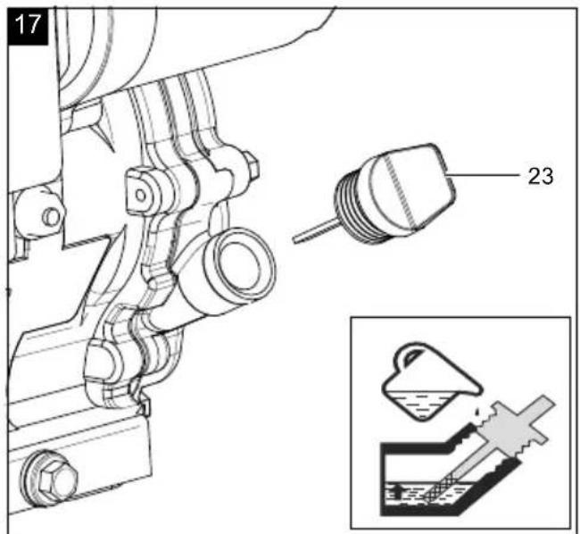
13.5 Checking the oil level (Fig. 17)
ATTENTION
Health hazard!
Inhaling petrol/lubricant vapours may lead to severe health damage, loss of consciousness and, in extreme cases, to death.
- Do not inhale petrol/lubricant vapours.
- Operate the product outdoors only.
NOTE!
Product damage
Using the product without or with too little engine and gear oil can result in engine damage.
- Fill with petrol and oil before commissioning. The product is supplied without engine and gearbox oil.
- Only use unleaded petrol with a minimum RON of 95 and a maximum bioethanol content of 10%. (E10)
- Only use engine oil SAE 10W-30.
NOTE!
Environmental damage!
Spilled oil can pollute the environment permanently. The liquid is highly toxic and can quickly lead to water pollution.
- Fill/empty oil only on level, paved surfaces.
- Use a filling nozzle or funnel.
- Collect drained oil in a suitable container.
- Wipe up spilled oil carefully immediately and dispose of the cloth according to local regulations.
-
Dispose of oil as per local regulations.
-
Place the product on a level, even surface.
-
Remove the ignition key (L) from the ignition lock (model-dependent).
-
Remove the spark plug connector (35) from the spark plug (36).
-
Unscrew the oil filler cap with oil dipstick (23).
-
Wipe the oil filler cap with oil dipstick (23) with a clean, lint-free cloth.
-
Screw the oil filler cap with oil dipstick (23) back into the filling nozzle until it reaches the stop.
-
Unscrew the oil filler cap with oil dipstick (23) and read the oil level in the horizontal position. The oil level must be between L (Low) and H (High) on the oil filler cap with oil dipstick (23).
- If the oil level is too low, top up the oil as described in section 9.1.
- Then screw the oil filler cap with oil dipstick (23) back on.
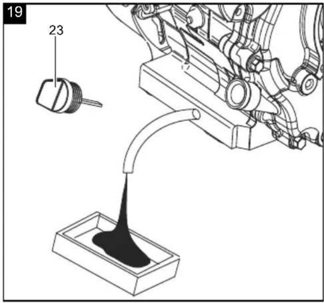
13.6 Oil change (Fig. 19)
ATTENTION
Health hazard!
Inhalation of fuel / lubricating oil vapours and exhaust gases can cause serious damage to health, unconsciousness and in extreme cases death.
- Do not breathe fuel / lubricating oil vapours and exhaust gases.
- Operate the product outdoors only.
ATTENTION
Product damage!
If the product is operated without or with too little engine oil, this can lead to product damage.
- Fill with fuel and oil before commissioning. The product is delivered without engine oil.
ATTENTION
Environmental damage!
Spilled oil can pollute the environment permanently. The liquid is highly toxic and can quickly lead to water pollution.
- Fill/empty oil only on level, paved surfaces.
- Use a filling nozzle or funnel.
- Collect drained oil in a suitable container.
- Wipe up spilled oil carefully immediately and dispose of the cloth according to local regulations.
- Dispose of oil as per local regulations.
Change the engine oil after the first 50 operating hours.
The engine oil change should be carried out while the motor (5) is at operating temperature.
- Place the product on a level, even surface.
- Remove the ignition key (L) from the ignition lock (model-dependent).
-
Remove the spark plug connector (35) from the spark plug (36).
-
Unscrew the oil dipstick (23).
-
Have a suitable collection bucket to hand.
-
Open the oil drain screw (25). Use an open-ended spanner size 12 mm.
- Allow the oil to drain into a collection bucket.
- Close the oil drain screw (23) again once the oil has drained completely. Use an open-ended spanner size 12 mm.
- Fill up with new SAE 10W-30 engine oil (approx. 6.5 l).
- Wipe the oil dipstick (23) with a clean, lint-free cloth.
- Screw the oil dipstick (23) back into the filler neck until it reaches the stop.
- Screw the oil dipstick (23) out and read the oil level in the horizontal position. The oil level must be between L (Low) and H (High).
- If the oil level is too low, top up the oil as described in section 9.1.
- Dispose of the used oil properly.
Dispose of the used oil in accordance with applicable regulations.
13.7 Drain petrol with a petrol extraction pump
In the case of storage over a longer period of time, the petrol must be drained.
- Place the product on a level, even surface.
- Remove the ignition key (L) on the ignition lock (model-dependent)
- Remove the spark plug connector (35) from the spark plug (36).
- Hold a collection bucket under the hose on the petrol extraction pump.
- Unscrew and remove the fuel filler cap (16).
- Remove the fuel filter insert (24).
- Push the petrol extraction pump's hose into the fuel tank (15) and drain the petrol completely using the petrol extraction pump.
- Reinsert the fuel filter insert (24).
- Retighten the fuel filler cap (16).
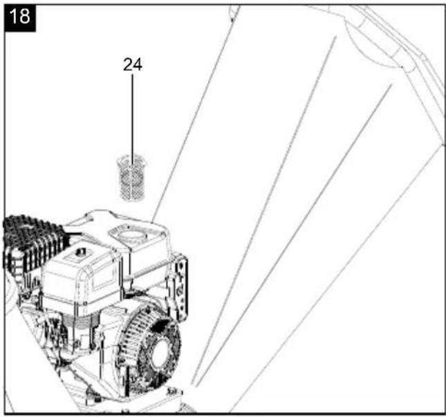
13.8 Cleaning the fuel filter insert (24) (Fig. 18)
Note: The fuel filter insert (24) is a filter cup which is located directly under the tank cover (16) and filters all the fuel filled in.
- Unscrew the fuel filler cap (16).
- Remove the fuel filter insert (24). Clean it in a non-flammable solvent or a solvent with a high flash point.
- Reinsert the fuel filter insert (24).
- Retighten the fuel filler cap (26).
13.9 Tensioning the V-belt (34) (Fig. 20)
Note: The V-belt (34) must be re-tensioned after five operating hours.
- Place the product on a level, even surface.
-
Remove the ignition key (L) from the ignition lock (model-dependent). Remove the spark plug connector (35) from the spark plug (36).
-
Remove the V-belt cover (20) by removing the four hexagonal bolts (B) using a 10 mm open-ended spanner.
-
Check the V-belts (34) by pressing with your thumb. If it gives by more than 10-15 mm, the V-belts (34) must be re-tensioned.
-
In order to tension the V-belts (34), loosen each of the V-belt tensioning screws and lock nuts using a size 13 mm open-ended spanner/ratchet spanner with an extension on both sides of the engine (5).
-
Use a size 13 mm open-ended spanner/ratchet spanner with extension to loosen the four engine/shredding unit connection screws (5).
-
Use the two belt tensioning screws to re-tension the V-belts (34).
-
Check the V-belts (34) by pressing with your thumb. If the V-belts (34) give by more than 10-15 mm, the V-belts (34) must be re-tensioned.
-
Lock the two belt tensioning screws with one lock nut each.
-
Re-attach the V-belt cover (20) and secure it with four hexagonal bolts.
13.10 Replacing the V-belt (34) (Fig.20)
Note: If the V-belts (34) are torn, worn out or smooth, they must be replaced.
- Place the product on a level, even surface.
- Remove the ignition key (L) from the ignition lock (model-dependent).
-
Remove the spark plug connector (35) from the spark plug (36).
-
Remove the V-belt cover (20) by removing the four hexagonal bolts (B) using a 10 mm open-ended spanner.
-
To replace the V-belts (34), loosen each of the V-belt tensioning screws and lock nuts using a size 13 mm open-ended spanner/ratchet spanner with an extension on both sides of the engine (5).
-
Use a size 13 mm open-ended spanner/ratchet spanner with extension to loosen the four engine/shredding unit connection screws (5).
-
Remove the old V-belts (34).
-
Pull the V-belts (34) on correctly. (Pay attention to the running direction!)
-
Tension the V-belt (34) as described in section 13.9
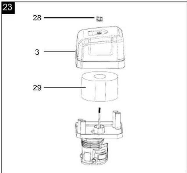
13.11 Maintenance of the air filter (29) (Fig.23)
⚠️ Danger
Risk of fire and explosion!
If not cleaned correctly, fuel may ignite and even explode. This can lead to severe burns or death.
- Clean the air filter only by knocking it out.
- Never clean the air filter with petrol or flammable solvents.
ATTENTION
Risk of damage!
Operating the engine without a filter element or with a damaged filter element can cause engine damage.
- Never run the engine without the air filter element or with a damaged filter element. This would allow dirt into the engine, which would result in severe damage to the engine.
ATTENTION
Contaminated air filters diminish the engine output due to reduced air supply to the carburettor. Regular inspection is therefore essential.
Contaminated air filters (29) diminish the engine output due to reduced air supply to the carburettor. Regular inspection is therefore essential.
The air filter (29) should be checked every 25 operating hours and cleaned as required. The air filter (29) must be checked more often if the air is very dusty.
- Remove the air filter cover (3) by removing the wing screw (28).
- Remove the air filter (29).
- Clean the air filter (29) only by knocking it out.
- Replace a faulty air filter (29) with a new one.
- Re-insert the air filter (29) and use the wing screw (28) to fit the air filter cover (3).
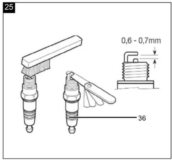
13.12 Maintenance of the spark plug (36) (Fig. 25)
Check the spark plug (36) for contamination for the first time after 20 operating hours and clean it with a copper wire brush if necessary. Then maintain the spark plug (36) every 50 operating hours.
- Place the product on a level, even surface.
- Remove the ignition key (L) from the ignition lock (model-dependent).
- Remove the spark plug connector (35) from the
spark plug (36).
- Use the spark plug spanner (A) to remove the spark plug (36).
- Remove any dirt from the base of the spark plug (36)
- Visually inspect the spark plug (36). Remove any deposits present using a copper wire brush.
- Check the spark plug gap. Use a feeler gauge to adjust the electrode gap to 0.6-0.7 mm.
- Replace the spark plug (36) and take care not to tighten it excessively.
- Then place the spark plug connector (35) on the spark plug (36).
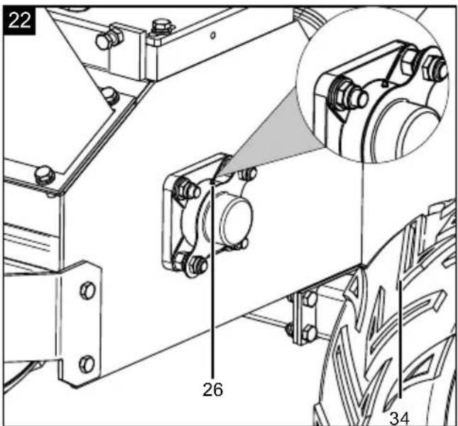
13.13 Lubricating the bearings (Fig.22)
Note: The bearings on both sides of the shredding unit must be regularly lubricated using a grease gun.
- Place the product on a level, even surface.
-
Remove the ignition key (L) from the ignition lock (model-dependent).
-
Remove the spark plug connector (35) from the spark plug (36).
- Remove the V-belt cover (20) by removing the four hexagon bolts with a size 10 mm open-ended/ratchet spanner.
- Remove the protective caps from the grease nipples on both sides.
- Use a lint-free cloth to clean the grease nipples on both sides.
- Use 1-2 pumps of the grease nipples to lubricate the bearings on both sides.
- Use a lint-free cloth to clean the grease nipples on both sides to remove excess grease.
- Fit the protective caps to the grease nipples on both sides.
Re-attach the V-belt cover (20) and secure it with four hexagonal bolts.
Maintenance plan
| Task: | Before every use | After 5 operating hours | Every 25 operating hours | Every 50 operating hours | Annually or every 100 operating hours |
| Refuel and check the oil level x | |||||
| Replace the oil x x x | |||||
| Replace the petrol x | |||||
| Clean / replace the petrol filling funnel x | |||||
| Clean the air filter (29) x x | |||||
| Replace the air filter (29) | x | ||||
| Inspect the spark plug (36) and the spark plug connector (35) | x | x | |||
| Replace the spark plug (36) | x | ||||
| Cleaning the spark plug (36) | x | ||||
| Inspect the product for damage and to ensure it is functioning | x | ||||
| Inspect the V-belts (34) | x | ||||
| Re-tension the V-belts (34) | x | ||||
| Inspect the blades/counter-blades (5) | x | ||||
| Lubricate the bearings | x | ||||
| Check the tyre pressure | x | ||||
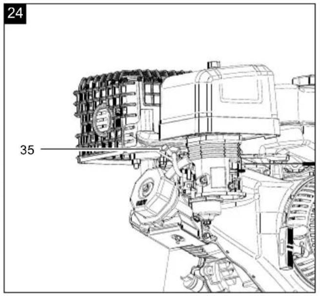
| Inspect the exhaust system (27) | x x | ||||
| Re-tighten all screws | x | ||||
| Check that the EMERGENCY STOP is functioning | x | ||||
| Lubricating the knife drum | x |
14. Storage
⚠ WARNING
Risk of fire and explosion!
Storing the product near potential sources of ignition can result in a fire or an explosion. This can lead to severe burns or death
- Eliminate possible sources of ignition, such as furnaces, hot water boilers with gas, gas dryers, etc.
NOTE!
Risk of damage!
If the product is not stored properly, the engine can be damaged.
- Store the product protected against dirt, dust and moisture.
Required tool
- Petrol extraction pump *
- Oil filler bottle *
- Open-ended/ratchet spanner size 13 mm *
- Open-ended/ratchet spanner size 16 mm *
- Car battery charger *
* = may not be included in the scope of delivery!
14.1 Preparation for storage
If the product will not be used for a period of more than 30 days, the following measures must be taken to prepare it for storage.
WARNING
Do not remove the petrol in enclosed spaces, near fire or when smoking. Petrol fumes can cause explosions and fire.
- Empty the fuel tank (15) using a petrol extraction pump.
- Start the engine (5) and let it run until the remaining petrol is used up.
- Change the oil at the end of every season. To do so, remove the used engine oil from a warm engine and refill with fresh oil.
- Remove the spark plug connector (35) from the spark plug (36).
- Fill the cylinder with approx. 20 ml of oil from an oil filling bottle.
- Pull the pull starter (30) slowly so that the oil protects the inside of the cylinder.
-
Be sure to clean the entire product to protect the paint.
-
Store the product in a well-ventilated place or area.
- Store the product and its accessories in a dark, dry and frost-free place that is inaccessible to children. The optimum storage temperature lies between 5 and 30 °C.
- Store the tool in its original packaging. Cover the tool to protect it from dust or moisture. Store the operating manual with the tool.
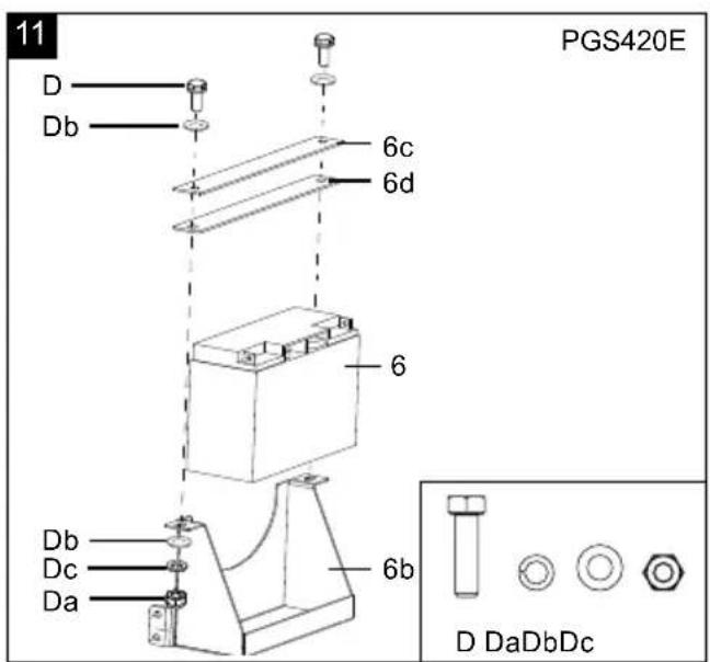
14.2 Removing the battery (6) (model-dependent)
- Disconnect the battery (6).
- To do this, connect the black cable to the negative terminal (-) and the red cable to the positive terminal (+).
- To remove the battery retaining plate (6c), loosen the two hexagonal bolts (D) using a size 13 mm open-ended spanner.
- Remove the battery (6) from the battery holder (6b)
- Screw the battery retaining plate (6c) back on with both hexagon bolts.
Ensure that battery (6) is secured to prevent unauthorised use (e.g. by children).
Charge the battery (6) during the winter 1-2 times to ensure that the full charging capacity is maintained. Incorrect storage can damage the battery (6) and voids the guarantee.
14.3 Charge battery (6) with a battery charger for car batteries (model-dependent)
⚠️ Danger
Danger due to charging the battery incorrectly!
If the charging voltage is too high, there is a risk of the battery (6) exploding.
Always remove the ignition key (L) from the ignition when working on the battery (6).
- The charging current of the battery charger must not exceed 5 A and the charging voltage must not exceed 14.4 V.
- Remove the battery (6) as described in Section 14.2
- Connect the battery (6) to a battery charger designed for car batteries. First, connect the red cable to the positive terminal (+) and the black cable to the negative terminal (-) of the charging unit.
- Charge the battery (6) for at least 5 hours.
ATTENTION
Danger of short circuit!
- To avoid a short circuit, always disconnect the negative cable (-) from the battery (6) first and reconnect it last.
- When connecting/disconnecting the battery (6), ensure that the poles (+/-) do not touch each other and/or the frame.
- Please note the correct order!
15. Repair & ordering spare parts
After repairs or maintenance, make sure that all safety-related parts are installed and are in perfect condition. All parts which may cause injury must be kept where they are inaccessible to children or others.
Attention: According to the German Product Liability Act, no liability is accepted for damage caused by improper repairs or by not using original spare parts.
Such work should be performed by a customer service centre or an authorised specialist. The same applies to accessory parts.
Connections and repairs
Connections and repair work on the electrical equipment may only be carried out by electricians.
Please provide the following information in the event of any queries:
• Type of current for the motor
• Machine data - type plate
• Motor data - type plate
Important note in the case of repairs:
For return delivery of the product for repair, please ensure for safety reasons that it is free of oil and fuel when it is sent to the service centre.
Spare parts and accessories can be obtained from our service centre. To do this, scan the QR code on the cover page.
15.1 Ordering spare parts
Please provide the following information when ordering spare parts:
- Model designation
- Item number
- Type plate data
15.2 Service information
With this product, it is necessary to note that the following parts are subject to natural or usage-related wear, or that the following parts are required as consumables.
Wearing parts*: V-belt, engine oil, spark plug, air filter, wheels, support wheel, rubber lip, blade, battery
* may not be included in the scope of delivery!
16. Disposal and recycling
Notes for packaging


The packaging materials are recyclable. Please dispose of packaging in an environmentally friendly manner.
Notes on the electrical and electronic equipment act (ElektroG)
Waste electrical and electronic equipment does not belong in household waste, but must be collected and disposed of separately!
- Used batteries or rechargeable batteries that are not installed permanently in the old device must be removed non-destructively before disposal! Their disposal is regulated by the battery act.
- Owners or users of electrical and electronic devices are legally obliged to return them after use.
- The end user is responsible for deleting their personal data from the old device being disposed of!
- The symbol of the crossed-out dustbin means that waste electrical and electronic equipment must not be disposed of with household waste
- Waste electrical and electronic equipment can be handed in free of charge at the following places:
- Public disposal or collection points (e.g. municipal works yards).
- Points of sale of electrical devices (stationary and online), provided that dealers are obliged to take them back or offer to do so voluntarily.
- Up to three waste electrical devices per type of product, with an edge length of no more than 25 centimetres, can be returned free of charge to the manufacturer without prior purchase of a new device from the manufacturer or taken to another authorised collection point in your vicinity.
- Further supplementary take-back conditions of the manufacturers and distributors can be obtained from the respective customer service.
- If the manufacturer delivers a new electrical device to a private household, the manufacturer can arrange for the free collection of the old electrical device upon request from the end user. Please contact the manufacturer's customer service for this.
• These statements only apply to devices installed and sold in the countries of the European Union and which are subject to the European Directive 2012/19/EU. In countries outside the European Union, different regulations may apply to the disposal of waste electrical and electronic equipment.
Information on the battery act [BattG]
![SCHEPPACH PGS420SE - Information on the battery act [BattG] - 1](/content/2026/05/755814/images/1e290c41e9fa186945ea1d9aef79a85ff9ba1c90b3c216f58114c81a3b482291.jpg)
Old batteries and rechargeable batteries do not belong in household waste, but must be collected or disposed of separately!
- For safe removal of batteries or rechargeable batteries from the electrical device and for information on their type or chemical system, please refer to the additional information in the operating or assembly instructions.
- Owners or users of batteries and rechargeable batteries are legally obliged to return them after use. The return is limited to household quantities.
- Old batteries may contain pollutants or heavy metals that can harm the environment or human health. Recycling old batteries and using the resources they contain helps to protect these two important issues.
- The symbol of the crossed-out dustbin means that batteries and rechargeable batteries must not be disposed of with household waste.
- If the signs Hg, Cd or Pb are also located below the dustbin symbol, this stands for the following:
- Hg: Battery contains more than 0.0005% mercury
- Cd: Battery contains more than 0.002% cadmium
- Pb: Battery contains more than 0.004% lead
- Rechargeable batteries and batteries can be returned free of charge to the following places:
- Public disposal or collection points (e.g. municipal works yards)
- Sales points for batteries and rechargeable batteries
- Take-back points of the common take-back system for old device batteries
- Take-back point of the manufacturer (if not a member of the common take-back system)
• These statements are only valid for rechargeable batteries and batteries sold in the countries of the European Union and subject to the European Directive 2023/1542/EC. In countries outside the Euro-
pean Union, different regulations may apply to the disposal of rechargeable batteries and batteries.
You can find out how to dispose of the disused product from your local authority or city administration.
Fuels and oils
- Before disposing of the product, the fuel tank and the engine oil tank must be emptied!
- Fuel and engine oil do not belong in household waste or drains, but must be collected or disposed of separately!
- Empty oil and fuel tanks must be disposed of in an environmentally friendly manner.
17. Troubleshooting
The following table shows fault symptoms and describes remedial measures in the event of your product failing to work properly. If you cannot localise and rectify the problem with this, please contact your service workshop.
| Fault Possible cause Remedy | ||
| The engine (5) does not start. | The spark plug connector (35) is disconnected. | Connect the spark plug connector (35) to the spark plug (36) properly. |
| The fuel is empty or stale. Fill with new fuel. | ||
| The throttle (33) is not in the correct start position. | Move the throttle (33) to the start position. | |
| The choke lever (32) is not in the “ON” position. | The choke lever (32) must be in the “ON” position for a cold start. | |
| The fuel line is blocked. Clean the fuel line. | ||
| Sooty spark plug (36). Clean, set gap or replace. | ||
| Too much fuel inside the combustion chamber. | Wait a few minutes before restarting. Do not prime. | |
| The engine (5) splutters. | The spark plug connector (35) is loose. Connect the spark plug connector (35) to the spark plug (36) properly. | |
| The choke lever (32) is in the “ON” position. Set the choke lever (32) to the “OFF” position. | ||
| The fuel line is blocked or the fuel is stale. | Clean the fuel line. Fill the fuel tank (15) with new fuel. | |
| The air filter (29) is clogged. Clean or replace the air filter (29). | ||
| There is water or dirt in the fuel system. Empty the fuel tank (15). Fill with new fuel. | ||
| The air filter (29) is dirty. Clean or replace the air filter (29). | ||
| The carburettor is not adjusted correctly. See the engine manual. | ||
| The engine (5) is overheating. | The oil level in the engine (5) is too low. Add the correct oil to the engine (5). | |
| The air filter (29) is dirty. Clean or replace the air filter (29). | ||
| The carburettor is not adjusted correctly. See the engine manual. | ||
| Power decreases, poor cutting performance. | The blade is blunt or used up. | Sharpen the blade or replace it completely. |
| Heavy vibrations / loud noises. | The blade screws/counter-blade screws are loose. | Tighten the blade screws/counter-blade screws. |
| Blades/counter-blades damaged. | Replace the blades/counter-blades. | |
| Product is damaged inside. | Contact customer service. | |
Günzburger Straße 69
D-89335 Ichenhausen
Remarque :
Günzburger Straße 69
D-89335 Ichenhausen, Germania
Indicazione:
Günzburger Straße 69
D-89335 Ichenhausen
Aanwijzing:
Günzburger Straße 69
Günzburger Straße 69
Günzburger Straße 69
D-89335 Ichenhausen
Upozornění:
Günzburger Straße 69
D-89335 Ichenhausen
Upozornenie:
Günzburger Straße 69
D-89335 Ichenhausen
Megjegyzés:
Günzburger Straße 69
D-89335 Ichenhausen
Wskazówka:
Günzburger Straße 69
D-89335 Ichenhausen
Napomena:
Prema važećem njemačkom Zakonu o odgovornosti za proizvode, proizvođač ovog proizvoda ne odgovara za štete koje nastanu na ovom proizvodu ili koje ovaj proizvod uzrokuje u slučaju:
- neispravnog rukovanja
- Nepridržavanje priručnika za uporabu
Günzburger Straße 69
D-89335 Ichenhausen
Napotek:
Proizvajalec tega izdelka skladno z veljavnim zakonom o odgovornosti za izdelke ne jamči za poškodbe na tem izdelku ali poškodbe s tem izdelkom, do katerih pride pri:
Günzburger Straße 69
D-89335 Ichenhausen
Juhis:
Günzburger Straße 69
D-89335 Ichenhausen
Nuoroda:
Günzburger Straße 69
Günzburger Straße 69
D-89335 Ichenhausen
Anvisning:
Günzburger Straße 69
D-89335 Ichenhausen
Huomautus:
Günzburger Straße 69
D-89335 Ichenhausen, Tyskland
Bemærk:
Günzburger Straße 69
D-89335 Ichenhausen
Merknad:
12.1 Forberedelse for transport
- Tøm drivstofftanken (15) med en bensinsugepumpe.
Günzburger Straße 69
D-89335 Ichenhausen, Германия
Указание:
Günzburger Straße 69
D-89335 Ichenhausen
Υπόδειξη:
Günzburger Straße 69
D-89335 Ichenhausen
Indicatie:
Günzburger Straße 69
D-89335 Ichenhausen
Napomena:
Günzburger Straße 69
D-89335 Ichenhausen
İthalatçı:
PGS420E
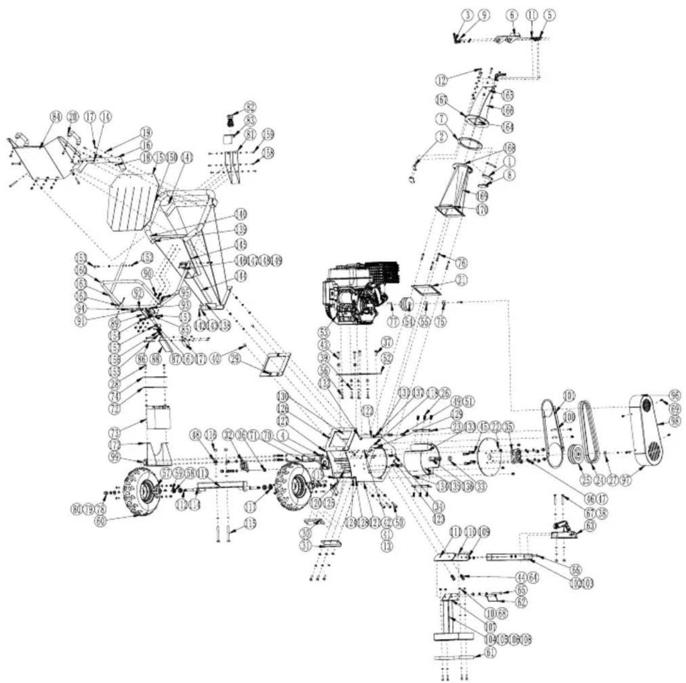
PGS420
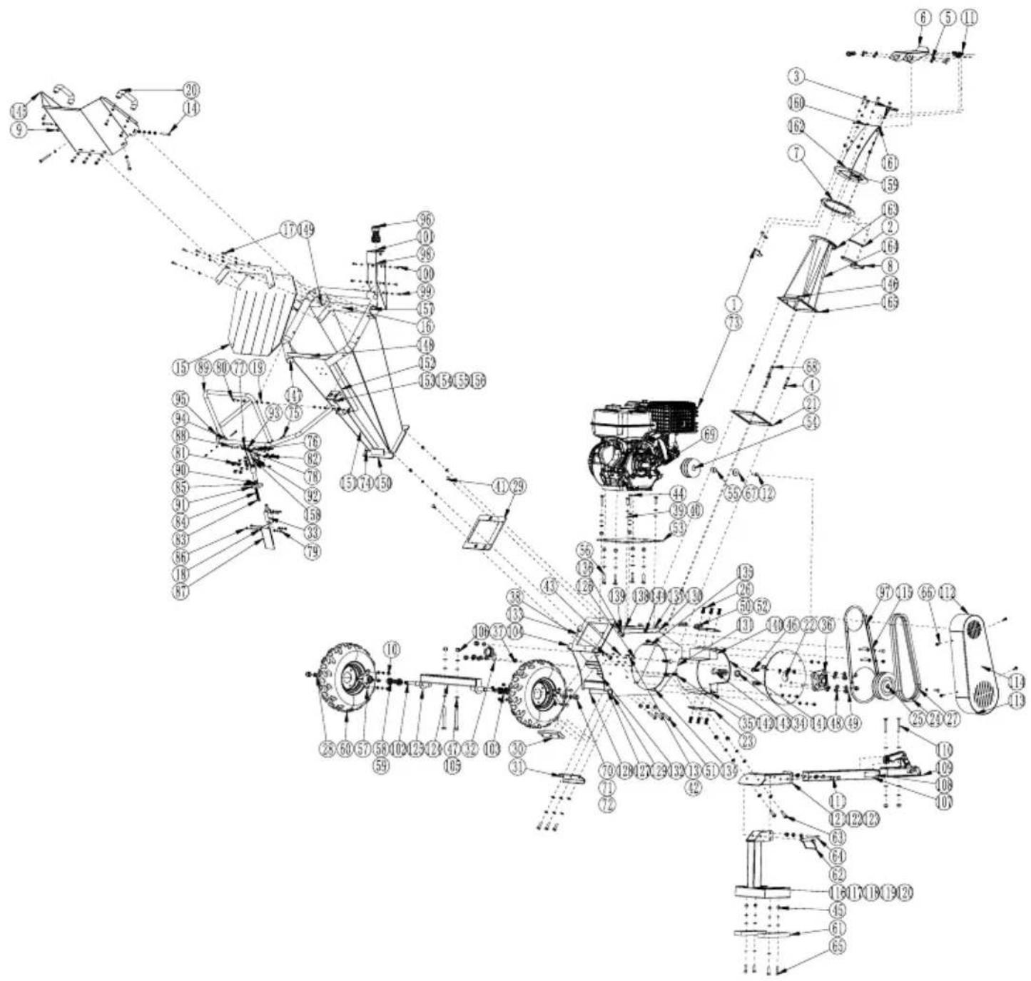
PGS420SE