19017 05904 - Saw SCHEPPACH - Free user manual and instructions
Find the device manual for free 19017 05904 SCHEPPACH in PDF.

User questions about 19017 05904 SCHEPPACH
0 question about this device. Answer the ones you know or ask your own.
Ask a new question about this device
Download the instructions for your Saw in PDF format for free! Find your manual 19017 05904 - SCHEPPACH and take your electronic device back in hand. On this page are published all the documents necessary for the use of your device. 19017 05904 by SCHEPPACH.
USER MANUAL 19017 05904 SCHEPPACH
text_image
scheppachD Formatkreissäge
GB Panel Sizing Circular Saw

natural_image
Technical line drawing of a machine tool with no visible text or symbolsInhalt · Content · Sommario · Contenido
D
Translation from original manual 20 - 36
Hersteller:
Scheppach
Günzburger Straße 69
D-89335 Ichenhausen
Allgemeine Hinweise
natural_image
Technical line drawing of a mechanical assembly with mounting brackets and a rod (no text or symbols)Abb. B

natural_image
Technical line drawing of a mechanical assembly with directional arrows indicating motion or force (no text or symbols present)Abb. C

natural_image
Technical line drawing of a mechanical assembly with no visible text or symbolsAbb. D

natural_image
Technical line drawing of a mechanical component with a central circular feature and mounting holes (no text or symbols)Montage
text_image
Technical diagram of a mechanical assembly with numbered components, likely a machine or industrial component.Abb. F

natural_image
Technical line drawing of a mechanical device with a saw blade and handle (no text or symbols)Abb. G

natural_image
Technical line drawing of a mechanical device with a rack and handle (no text or symbols)Abb. H
natural_image
Technical line drawing of mechanical components and linkages (no text or symbols)natural_image
Technical line drawing of a mechanical assembly with spring-loaded components and a central rotating component (no text or symbols)Abb. J

natural_image
Line drawing of a mechanical clamp with multiple wrenches and a base (no text or symbols)Abb. K

natural_image
Technical line drawing of a mechanical assembly with no visible text or symbolsAbb. L

natural_image
Technical line drawing of a mechanical assembly with no visible text or symbolsnatural_image
Technical line drawing of a mechanical assembly with no visible text or symbolsAbb. N

text_image
1 2 3text_image
Technical diagram showing exploded view of a mechanical device with labeled components including switch, screwdriver, and housing parts.Abb. R

natural_image
Technical line drawing of a mechanical assembly with labeled components (no text or symbols present)Inbetriebnahme
text_image
Technical diagram of a mechanical assembly with labeled parts 1 and 2, showing gear and workpiece components.Abb. T

natural_image
Technical line drawing of a mechanical gear assembly with no visible text or symbols
text_image
2mm 3-8mm 3-8mmAbb. U

natural_image
Technical line drawing of two mechanical assembly steps with no visible text or symbolsnatural_image
Technical line drawing of a mechanical gear assembly with labeled component A (no text or symbols beyond label)Abb. Y

text_image
0,1 mm/Q 1,5 mm/Q 3 4text_image
Technical diagram of an electric motor with labeled parts and directional arrows indicating motion or operation
natural_image
Technical line drawing of an industrial machine with mechanical components and no visible text or symbols
natural_image
Technical line drawing of a mechanical assembly with two hanging components and a textured base (no text or symbols)Günzburger Straße 69
D-89335 Ichenhausen
General Instructions
- Check all parts for possible damage after unpacking. Inform the shipper immediately if any damage has occurred.
- Later claims will not be accepted.
- Check that the shipment is complete.
- Read the operating instructions to familiarize yourself with the machine before use.
- Use only genuine accessories, wearing and spare parts. Spare parts are available from your local authorized dealer.
- When ordering be sure to include the article number and model and year of manufacture of the machine.
NOTE:
The manufacturer of this machine shall not be held liable for damage to this machine or resulting from use of this machine which result from:
- improper use
• noncompliance with the operating instructions
• repairs made by unauthorized third parties / technicians - installation and replacement of spare parts other than genuine scheppach spare parts
- operation which does not comply with the conditions for "proper use"
- power failures in the electric power supply system, noncompliance with applicable electric regulations and VDE requirements 01 00, DIN 57113 / VDE 01 13.
We recommend that you:
Read the full text of the operating instructions before assembly and initial operation of this machine.
These operating instructions will help you to become familiar with this machine and tell you how to use it properly.
The operating instructions contain important information on how to operate this machine in a safe, professional and money saving manner, how to prevent hazards, save repair costs, reduce down times and increase the reliability and service life of this machine.
You must comply with local and national regulations which apply to the operation of this machine in addition to the safety instructions contained in the operating instructions.
The operating instructions should be kept in a plastic cover to protect against dirt and moisture and stored in close proximity to the machine. Each person who operates the machine must read the operating instructions before operating the machine and follow these instructions carefully. Only persons who have been trained in the use of this machine and instructed on the hazards associated with it may operate this machine. The required minimum age must be complied with.
In addition to the safety instructions provided in these operating instructions and applicable local and national regulations please follow generally recognized technical rules for the operation of wood cutting machines.
Table of contents
General Instructions 16
NOTE: 16
Summary of contents 16
Safety instructions 16
Proper Use 17
Additional Hazards 17
Special accessories 17
Special accessory sawblades 17
Noise Characteristics 19
Assembly 19
Initial Operation 20
| Maintenance | 21 |
| Electrical Connection | 22 |
| EG-Konformitätserklärung | 38 |
| Guarantee | 39 |
| Warranty | 39 |
This symbol is used throughout these operating instructions to indicate instructions which effect safety:

⚠️ Safety instructions
- Provide the safety instructions to every person who uses this machine.
- Use the machine in perfect technical condition only in a safe and careful manner which complies with the proper use described in the operating instructions! Immediately remedy any faults which could effect safety!
- Only tools which comply with European Standard EN 847-1 may be used.
- Follow all safety and danger instructions listed on the machine.
- All safety and danger instructions on the machine must be kept fully legible.
- Never use the panel sizing circular saw to cut firewood.
- Caution during use: the rotating cutting tool could cause injury to fingers and hands.
- Check power supply connections. Do not use damaged electrical cords.
- Make sure that the machine has been placed on a hard surface in a level and stable position.
- Keep children away from the machine when it has been connected to the power supply.
• Machine operators must be at least 18 years old.
Trainees must be at least 16 years old but may operate the machine under supervision only. - Do not distract persons using the machine.
- Keep the working area around the machine free of shavings and waste wood.
- If a second person is assigned to assist the machine operator by removing finished workpieces from the panel sizing circular saw the machine must be equipped with a table length extension. The second person should not stand any place other than at the output end of the table length extension.
- Use only saw blades which are well sharpened and free of cracks and deformities.
- Use of circular saw blades made of super speed steel is prohibited.
- Machine safety equipment should not be detached or disabled under any circumstances.
- The riving knife is an important safety device which guides the workpiece and prevents the cutting joint from closing behind the saw blade and the workpiece from being kicked backwards. Check the riving knife thickness
- refer to the numbers imprinted on the riving knife. The riving knife should never be thinner than the body of the saw blade or thicker than the cutting joint width.
- Lower the suction hood onto the workpiece during every working cycle.
- The hood must be positioned horizontally above the saw blade during every working cycle.
• Always use the push-stick when cutting narrow workpieces (less than 120 mm in width) lengthwise. - Switch off the machine during troubleshooting or to remove jammed pieces of wood. Disconnect power supply plug!
- Wear close-fitting garments. Do not wear jewelry, rings or wrist-watches.
- Check direction of motor and tool rotation (refer to "Electrical Connection").
- Machine safety equipment should not be detached or disabled under any circumstances.
- The motor must be switched off during any conversion, adjustment, measurement and cleaning work to the machine. Disconnect the power supply plug and wait until the rotating saw has come to a complete stop.
- Switch off the machine before remedying faults. Disconnect power supply plug!
- The machine must be connected to a dust extractor at all times during use. Follow the instructions for proper use.
- All safety equipment and hoods must be installed to operate the machine.
- Prior to initial operation the machine must be connected to a dust extractor by means of a flexible, non-flammable suction hose.
- The dust extractor should switch on automatically when the panel sizing circular saw is activated.
- Switch off the motor when leaving the work area. Disconnect power supply plug!
- Always disconnect the machine from all external power sources before moving it, no matter how slightly! Reconnect the machine to the power supply before restarting the machine!
- Installation, repair and maintenance work on the electrical equipment should be done by qualified electricians only.
- All safety equipment and protective devices must be reattached as soon as repair and maintenance work has been completed.
Proper Use
- This machine complies with the applicable EC machine guideline.
- This machine has a work area located in front of the machine to the left or right of the saw blade.
- To prevent accidents the work area and the area around the machine must be clear of any foreign objects which could interfere with machine operation.
- Workpieces should not contain any foreign objects such as nails or screws.
- Prior to initial operation the machine must be connected to a dust extractor by means of a flexible, non-flammable suction hose.
- For use in closed spaces the machine must be connected to a dust extractor. Use a ha 3200 or ha 2600 dust extractor to extract wood shavings or sawdust. The flow rate at the suction connection piece should be 20m / s . Partial vacuum 1200Pa .
- The automatic switch on device is available as a special
accessory.
Type ALV 2 Art. No. 7910 4010 230 V/50 Hz
Type ALV 10 Art. No. 7910 4020 400 V/50 Hz
When the machine is switched on the dust extractor switches on automatically after a 2 - 3 second time delay. This prevents overstress to the house fuse.
After the machine has been switched off the dust extractor continues to run for 3 - 4 seconds before switching off automatically.
This ensures that residual dust is extracted in accordance with the hazardous materials ordinance. This conserves electricity and reduces noise. The dust extractor runs only when the machine is in operation.
For industrial work use the rg 4000 dust extractor.
Do not switch off or remove dust extractors when the machine is in operation.
- The panel sizing circular saw is designed for use in processing wood or wood-like materials only. Use genuine parts and accessories only. Select the correct saw blade according to type of cut and type of wood (solid wood, plywood or particle board) in accordance with EN 847-1. Refer to the special accessories list.
- The manufacturer shall not be held liable for improper use!!
Additional Hazards
This machine is designed in accordance with state of the art technology and accepted standards of technical safety. In spite of this certain additional hazards may occur during operation of this machine.
- Risk of injury to fingers and hands from rotating saw or workpiece if saw or workpiece is routed improperly.
- Risk of injury from rotating saw resulting from improper mounting or guide control or from operation without end stop.
- Health risks due to excessive noise. Permissible noise levels are exceeded during operation of the machine. Always wear ear protection.
- Risk of injuries from defective saw blade. Check blade condition regularly.
- Electrical hazards if improper connection cables are used.
- In spite of all safety precautions instituted additional unforseeable hazards may occur.
- To minimize the risk of additional hazards follow all "safety instructions", instructions for "proper use", and operating instructions carefully.
Special accessories
| Art. No. | |
| Workpiece holder | 5472 0702 |
| Cross table with telescopic arm | 5472 0704 |
| Cross table with telescopic arm | 5472 0705 |
| SUVA exhaust device | 5472 0707 |
| Automatic switch on device ALV 2 | 7910 4010 |
| Automatic switch on device ALV 10 | 7910 4020 |
| Table extension | 790170070 |
| Forsa 4.0 / Forsa 4.1 | ||||
| Scope of delivery | ||||
| panel sizing circular saw - partly assembled | ||||
| saw blade ∅ 315 | ||||
| fence | ||||
| square edge stop | ||||
| crosscut / mitre gauge | ||||
| push-stick | ||||
| push-grip | ||||
| assembly tools | ||||
| holding mandrel | ||||
| assembly accessories (accessories bag) | ||||
| operating instructions booklet | ||||
| Precut saw blade ø120 (only 1901701904 / 1901705904) | ||||
| Technical Data | ||||
| Overall length: Forsa 4.0 16 | 7 mm / Forsa 4.1 | |||
| Overall length: with table extension | 1400 mm | |||
| Overall width 760 mm | ||||
| Overall height 1110 mm | ||||
| Table size 815 x 450 mm | ||||
| Table height 850 mm | ||||
| Circular saw blade ø min.-max. | 250-315 mm | |||
| r.p.m. 4000 1/min | ||||
| Cutting speed 66 m/sec | ||||
| Precut saw blade ø 120 mm | ||||
| r.p.m - precut saw blade 8000 1/min | ||||
| Cutting speed - precut 50 m/sec. | ||||
| Angling fence 0-60° | ||||
| Radial stop-guidance T-Profi | ||||
| Suction connection piece ø 50 mm | ||||
| Suction connection piece ø 100 mm | ||||
| Suction volume flow at 20 m/s ø 100 | 560 m3/h | |||
| Partial vacuum at suction connection piece junction ø 100 | 170 Pa | |||
| Partial vacuum at suction connection piece junction ø 50 | 918 Pa | |||
| Weight/Weight with precutter | 310/320 kg | |||
| Ambient conditions | -5°C - +35°C | |||
| Cutting data | ||||
| Cutting height at 90° | 110 mm | |||
| Cutting height at 45° 77 mm | ||||
| Saw blade regulating range | 110 mm | |||
| Parallel stop length | 800 mm | |||
| Parallel stop width max. | 390 mm | |||
| Parallel cut width with Fold out table width extension | 1100 mm | |||
| Cutting width 90° angular cut: | ||||
| with crosscut table 270 mm | ||||
| with sliding table 1400 | 900 mm | |||
| with sliding table 2000 | 960 mm | |||
| Drive | ||||
| Motor | 400V/50 Hz | |||
| Rated input P1 4,8 kW | ||||
| Output P2 | 4,0 kW | |||
| Motor speed | 2800 1/min. | |||
| Operating mode | S6/40% | |||
| Rated current 8,2 A | ||||
| Rated input P1 precutter | 0,8 kW | |||
| Output P2 precutter | 0,5 kW | |||
Special accessory sawblades
Only use original scheppach accessory!
Art.
Special sawblade 6310 4101
Carbide saw blade for coated furniture boards
Dimensions:
Total ∅ mm 250
Borehole ∅ mm 30
Number of teeth 80 Z
Saw blade 5100 5556
Universal blank blade carbide placement for longitudinal and lateral
cuts in wood and chipboards.
Dimensions:
Total ∅ mm 315
Borehole ∅ mm 30
Number of teeth 48 WZ
Saw blade 5100 5504
Universal blank blade carbide placement for longitudinal and cross cuts in hardwood and chipboards.
Dimensions:
Total ∅ mm 300
Borehole ∅ mm 30
Number of teeth 48 WZ
Saw blade 5100 5507
Universal blank blade carbide placement for longitudinal and cross cuts in solid wood.
Dimensions:
Total ∅ mm 300
Borehole ∅ mm 30
Number of teeth 72 Z
Saw blade 7986 3001
Special saw blade – low noise, carbide placement for synthetically coated furniture boards.
Dimensions:
Total ∅ mm 300
Borehole ∅ mm 30
Number of teeth 60 Z
Saw blade 5100 5501
Universal blank blade for soft- and hardwood.
Dimensions:
Total ∅ mm 300
Borehole ∅ mm 30
Number of teeth 28 WZ
Pre-cut saw blade 5472 0313
Carbide saw blade for pre-cutting synthetically coated furniture boards
Dimensions:
Total ∅ mm 120
Borehole ∅ mm 20
Number of teeth 26 Z
Noise Characteristics
Measurement Requirements in Accordance with Draft Pre-Norm EN 1870-18: 1995-07
The values listed are emission measurements and therefore do not necessarily represent reliable work values. Though a correlation does exist between emission levels and
immision levels it is not possible to determine from this with reliability whether additional safety precautions are required or not. Factors which may influence existing work No. area immission levels are length of exposure, individual characteristics of the work area, other noise emission sources etc. (e.g. number of machines and other processes in the vicinity). Permissible work area noise levels may vary from country to country. The information provided here should however enable the user to better estimate hazards and risks.
sound power level in dB
idle L_WA = 97 dB(A)
operation L_WA = 100 dB(A)
sound pressure level in work area
in dB
idle LpAeq = 86 dB(A)
operation LpAeg = 87 dB(A)
A measurement error K = 4 dB applies for the emission values listed.
Dust Emission Data
The dust emission levels measured in accordance with the "Guidelines for Testing Dust Emission (Concentration Parameters) of Wood Processing Machines" issued by the Committee of Wood Experts are below
2 mg/m ^3 . This means compliance with the TRK air quality levels for wood dust which apply in the Federal Republic of Germany is ensured if the machine is connected to a proper operative suction unit with an air speed of not less than 20 m/s.

1 - Hose holder
2 - Table lenght extension
3 - Protection cover for sawblade and scoring
4 - Saw blade ∅ 315
5 - Suction hose ∅50
6 - Scoring saw blade ∅120
7 - Push stick
8 - Fine adjustment for ripping fence
9 - On/Off switch / main saw blade
10 - Kick switch
11 - On/Off switch / prescoring device
12 - Hand wheel - angle adjustment
13 - Hand wheel - height adjustment
14 - Height display
15 - Angle display
16 - Crosscut Mitre gauge
17 - Edging fence
18 - Ripping fence
20 - Electric affiliation
21 - Main switch (only 4,8 kW)
22 - Key SW30
23 - Holding mandrel
24 - Key SW19
25 - Key SW8 (only with scoring attachment)
26 - Hexagonal key SW5
27 - Hexagonal key SW4
29 - Kick switch
30 - Handle

text_image
Install and adjust, Fig. P1 - P2 (see page 10) Align the machine with a spirit level. Dazu die Gestellfüße bei Bedarf verstellen. (siehe ABB P) Attention, the machine must be on firm ground. Offset unvennes. For this purpose the feet • Loosen hexagonal nut (1) • offset height • clamp hexagonal nut (1) We recommend, fix the machine on the floor. There are drill holes on the feet.(2) sliding table screw distance adjusted 05007105 clamp the 4 nuts evenly 02144006 02093384 19017 00010 screw distance adjusted Gestell 02093602 02098506 02902109 02091334 0214 4006 0500 7105 Mount the handwheel firstly, Fig. N (see page 13) Lift the sliding table on the frame, ghe threaded bolt must fit into the holes Mount the sliding table with the 4 nuts ( 0500 7105 ) on the frame ( 0500 7105 ) Attention: clamp the 4 nuts evenly Control the machine after mounting 24 englishTransport
Take a pallet truck or a transport device 5300 0705
Don't lift the machine on the tables.

Fig. A

natural_image
Technical line drawing of a mechanical assembly with mounting brackets and a cylindrical component (no text or symbols)Fig. B

natural_image
Technical line drawing of a mechanical assembly with directional arrows indicating movement or force (no text or symbols present)Fig. C

natural_image
Technical line drawing of a mechanical assembly with no visible text or symbolsFig. D
natural_image
Technical line drawing of a mechanical component with a circular feature and mounting holes (no text or symbols)Assembly
Always disconnect the power supply plug before doing any assembly or conversion work.
For packing reasons your panel sizing circular saw is only partly assembled at delivery.
Assembly Tools
Scope of delivery includes:
1 single-head wrench 19 mm span
1 single-head wrench 30 mm span
1 hexagonal
head wrench 5 mm span
1 hexagonal
head wrench 6 mm span
Longitudinal stop, Fig. A
Screw the guide shaft on both shaft supports, do not tighten them yet.
2 discs 8
2 cylinder screws M 8 x 16
Fig. B
Pull both clamp levers upwards and locate the skid on the shaft.
Longitudinal stop - adjustment, Fig. C
Locate a straight, approx. 600 to 800 mm long guide rail to the saw blade to adjust the longitudinal stop precisely. Align the stop by measuring and adjusting the stop several times (X).
Tighten both cylinder screws now.
Adjust microfilm reading glass D
Position the stop rail against the saw blade and clamp the eccentric lever. Loosen the attachment bolts of the microfilm reading glass and set the graduation mark exactly above the zero line of the scale, subsequently fasten both screws again
Important!
Use a measuring rod with cutting widths under 120 mm.
Fig. E

text_image
Technical diagram of a mechanical assembly with numbered components and labeled partsFig. F

natural_image
Technical line drawing of a mechanical tool with a saw cutting through it (no text or symbols)Fig. G

natural_image
Technical line drawing of a mechanical device with a spring-loaded component and mounting base (no text or symbols)Fig. H

natural_image
Technical line drawing of a conveyor belt system with rollers and guide rails (no text or symbols)Fine adjustment, Fig. E
The fine adjustment is carried out by means of the adjustment spindle (3) with eccentric lever (1) locked and eccentric lever (2) opened.
Suction hood – with pre-cutter, Fig. F
Screw the round-head screw M 8 x 40 with disc and clamping lever in the suction hood. Tighten the suction hood onto the splitting wedge.
Suction hood – without pre-cutter, Fig. G
Screw the round-head screw M 6 x 40 with disc and clamping lever in the suction hood. Tighten the suction hood onto the splitting wedge.
IMPORTANT! The suction hood must be lowered onto the work piece with each process step.
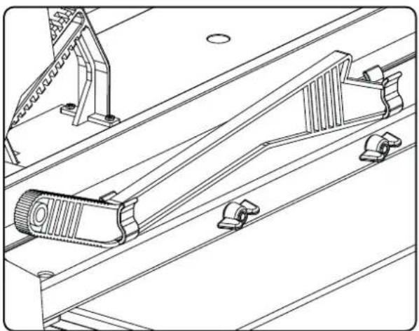
Measuring rod, Fig. H
Hang the measuring rod up on the provided screw under the sliding table.
Use a measuring rod when slitting small work pieces (smaller than 120 mm).
Fig. I

natural_image
Technical line drawing of a mechanical assembly with rollers and a tool (no text or symbols)Fig. J

natural_image
Line drawing of a hand tool holder with multiple wrenches and a screwdriver (no text or symbols)Fig. K
natural_image
Technical line drawing of a mechanical assembly with no visible text or symbolsFig. L

natural_image
Technical line drawing of a mechanical assembly with no visible text or symbolsSuction hose, Fig. I
Mount fastening plate for hose support on side of the machine. Guide suction hose 50 through the supporting bar, connect both ends and attach by means of the hose brackets.
Suction connections
Put the suction connections of the suction installation on the backside of the throw-off pipe.
Tool holder, Fig. J
Place the tool kit for the panel sizing circular saw in the tool holder for easy access.
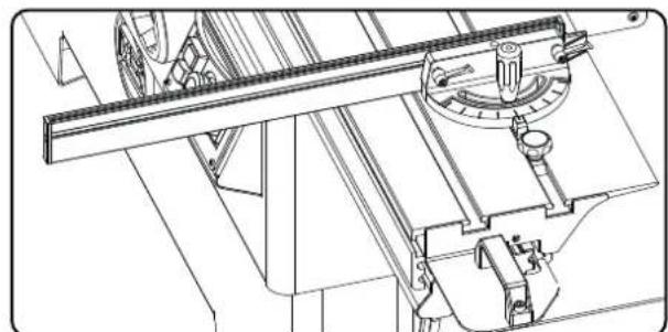
Cross cutter, Fig. K
The cross cutter can be attached to the sliding table. The continuous swivel range amounts to 60° at both sides and is fixated with the clamping device.
Trimming device, Fig. L
Attach the trimming device on the upper side of the sliding table.
Push the piece of work against the trimming device by means of the cross cutter
Fig. M

natural_image
Technical line drawing of a mechanical assembly with no visible text or symbolsFig. N

text_image
1 2 3Table extension, Fig. M
Attach the suspension bracket for the table extension to the machine. Subsequently screw on the suspension rod and tighten this by hand only.
4 Flange screws M8x20
Fig. N
Fig. Q

text_image
Technical diagram of a device control panel with labeled components including buttons, switches, and a screwdriver.Fig. R

text_image
Technical diagram showing mechanical components with labeled parts and angular measurementsInitial Operation
Read and follow the safety instructions prior to initial operation.
All safety and auxiliary equipment must be installed (tighten saw blow).
Connect your panel sizing circular saw to the power supply and it is ready for operation.
Note:
The manufacturer of this machine shall not be held liable for damage to this machine or resulting from use of this machine which result from:
- improper use
• noncompliance with the operating instructions
• repairs made by unauthorized third parties / technicians - installation and replacement of spare parts other than genuine scheppach spare parts.
- operation which does not comply with the conditions for "proper use"
- power failures in the electric power supply system, noncompliance with applicable electric regulations and VDE requirements 01 00, DIN 57113 / VDE 01 13.
Switch, Fig. Q
1 - On/off switch saw blade
2 - EMERGENCY STOP (only with pre-cutter)
3 - On/off switch pre-cutter
4 - Main switch (only with 4,8kW motor)
5 - Phase turner (check the sense of rotation upon
connection or relocation, alternately change the polarity.
Saw Blade Vertical Adjustment
Saw Blade Angle Adjustment, Fig. R
- To adjust blade height turn the handwheel manually counterclockwise or clockwise.
- Read out the set cutting height on the left scale with saw blade 315 mm.
- Saw blade 315 mm = cutting height of 0 - 110 mm
- Angular adjustment is carried out by simply turning hand wheel 2 to the left or to the right.
- For angular adjustment saw blade (max. 45°)
- Set the required cutting angle by turning the hand wheel.
- Reset the hand wheel to the end stop for resetting on 0^ .
Fig. S

text_image
Technical diagram of a mechanical assembly with labeled components 1 and 2, showing gear and workpiece connections.Fig. T
natural_image
Technical line drawing of a mechanical gear assembly with no visible text or symbols
text_image
2mm 3-8mm 3-8mmFig. U
natural_image
Technical line drawing of mechanical assembly components (no text or symbols)Changing Saw Blades Fig. S
Important:
Use only original saw blades which are well sharpened and free of cracks and deformities.
Important:
Disconnect power supply plug before changing the saw blade!
1 holding mandrel
2 M 20 left-handed hexagon nuts
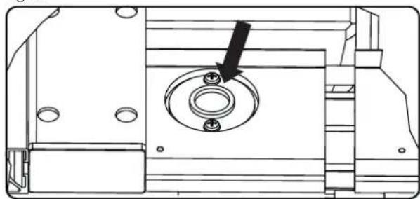
- Push panel sizing sliding table forwards; open protective cover using both hands.
- Insert the holding mandrel (1) into the saw spindle via the bore hole on the right table half. To unscrew or tighten the M 20 hexagon nuts (2) the saw spindle is locked using the holding mandrel.
- Check saw blade running direction.
Important: Saw runs only when protective cover is closed!
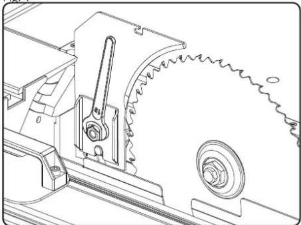
Riving Knife Fig T
Unscrew screw (3), insert and lock riving knife. The gap between saw blade and riving knife (4) must not exceed 8 mm and should be checked each time the saw blade is changed. The tip of the riving knife should never be set lower than the base height of the uppermost saw tooth. A setting of max. 2 mm below the tip of the uppermost saw tooth is best.
The riving knife is an important safety device which guides the workpiece and prevents the cutting joint from closing behind the saw blade and the workpiece from being kicked backwards. Check the riving knife thickness - refer to the numbers imprinted on the riving knife. The riving knife should never be thinner than the body of the saw blade or thicker than the cutting joint width.
Important!
The suction hood must be lowered onto the workpiece during every working cycle.
Measuring rod and sliding handle, Fig. U
- Use the measuring rod when cutting smaller pieces of work, with a distance of less than 120 mm between saw blade and stop rail.
- Use the sliding handle when sliding smaller, specially formed pieces of work. The corresponding sliding wood slats can be made by you and attached to the sliding handle.
Abb. V

text_image
1 4 SW 5 2 3Abb. W
natural_image
Technical line drawing of a mechanical gear assembly with labeled component A (no text or symbols beyond label)Abb. Y

text_image
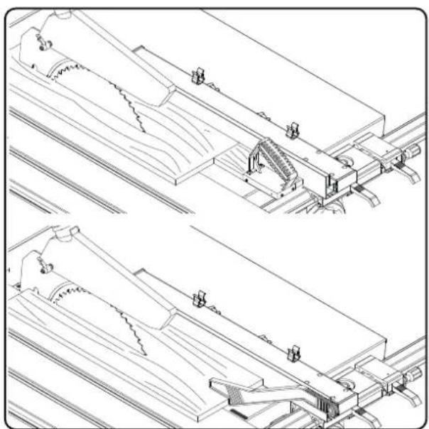
0,1 mm/Q 1,5 mm/QPre-cutter, Fig. V
IMPORTANT: Only insert sharpened, flawless, not deformed original Scheppach saw blades.
Replace the table insert when a sawing gap is made.
BE CAREFUL! Disconnect power plug when changing blades
1 Retain arbour
2 Flat headed screw M8
- Slide format sliding table forwards, open the protection cover with both hands.
- Insert the retain arbour (1) through the borehole of the right table half into the saw axle. Block the saw axle with the retain arbour to loosen or tighten the flat headed screw (2).
- Pay attention to the saw blade direction.
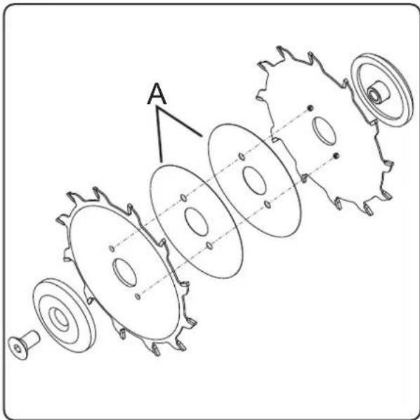
Fig. W, Y
- The overhang of the pre-cutter saw blades on the table surface is, depending on the cutting width of the machine's saw blades 1.0 – 2 mm.
- The height adjustment is carried out by means of the screw (2) Fig. V.
• 1 turning is 1.5 mm (picture Y) - The width of the pre-cutter saw blades is adjusted with the spacer (A) (1 x 0.1 mm, 2 x 0.2 mm, 1 x 0.3 mm) see Fig. W
- The pre-cutter should be as wide as the machine's saw blades.
2,8 mm - 3,6 mm are possible
- The flight of the pre-cutter saw blades to the machine's saw blades are adjusted by screw (3) picture V
• 1 turning is 0.1 mm (picture Y)
Carry out trial cut.
Lower the pre-cutter with the screw (2) under the table level when not in use.
Attention! Close protective cover again.
Maintenance
Switch off the motor and disconnect the power supply plug before doing any maintenance and cleaning work. Follow the following maintenance procedures for your panel sizing circular saw.
- Check belt tension after approx. 20 operating hour and tighten if necessary. To do this open the right side cover. Set required belt tension by adjusting the fastening nuts on the motor equally.
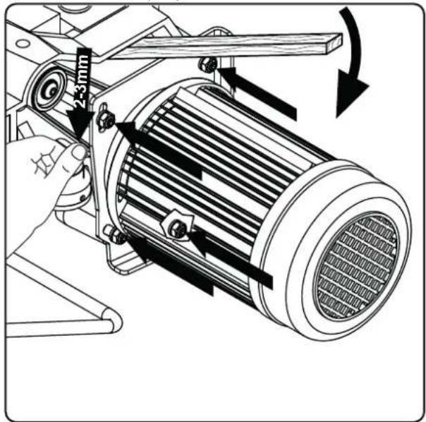
text_image
z-3 mm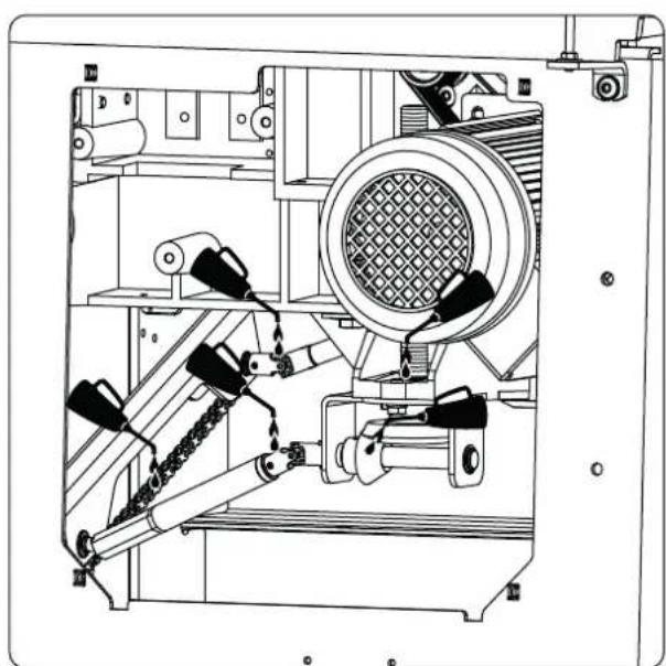
natural_image
Technical line drawing of an industrial machine with mechanical components and no visible text or symbols
natural_image
Technical line drawing of a mechanical assembly with two hanging sensors and a central component (no text or symbols)- Spray the roller chain and moving parts (vertical and swivel adjustment units) occasionally with dry lubricating spray. Open the right side cover.
- Check the sliding table carriage guide unit for dirt and clean if required.
• Always keep the table surface free of resin. - If a dust extractor is not being used the saw blade protective cover should be cleaned occasionally of any wood residue and sawdust. This is important for ensuring troublefree ejection of sawdust. If the machine is used without a dust extractor sawdust accumulation could reduce the vertical and angle adjustment range.
- Clean the sliding table carriage guide at regular intervals. All safety equipment and protective devices must be reattached as soon as repair and maintenance work has been completed.
- To ensure troublefree ejection of sawdust the saw blade protective cover should be cleaned of any wood residue.
- The vertical and angle adjustment range could be reduced if sawdust is allowed to accumulate. Open the protective cover and clean the adjustment area.
Electrical Connection
The built in electric motor is wired ready for operation. The connection conforms with the applicable VDE and DIN regulations.
The mains connection on site and the extension cable used should also comply with these regulations.
Motor Brake Device
Your panel sizing circular saw is equipped with an automatic shutdown brake. The brake starts to take effect after the driving motor switches off.
The saw blade must stop max.10 sec after switching off. Check daily!
Do not operate the machine after a longer braking time.
Important Information
The 230 V / 50 Hz and 400 V / 50 Hz electric motors are designed for S6 40 % operating mode.
If the motor starts to overload it switches off automatically. The motor can reactivated after a cooling period (exact interval differs).
Faulty Electric Connection Cables
Electric connection cables are frequently subjected to insulation damage.
Insulation damage results from:
- Pinch points where connection cables are routed through windows or door cracks.
- Kinks due to improper fastening or routing of connection cables.
- Cuts caused by running over connection cords.
- Insulation damage caused by pulling the cable out of the wall socket.
- Cracks due to aging.
Faulty or damaged electric connection cables are hazardous and should not be used under any circumstances as fatal injury could result.
Check electric connection cables regularly for damage. Before you check the connection cable, make sure that it has been completely disconnected from the power supply.
Electric connection cables must conform to the applicable VDE and DIN regulations. Use only connection cables
marked as H 07 RN.
Regulations require that the type designation be printed on the connection cable.
AC Motor
• The required supply voltage is 230 Volt - 50 Hz.
- Extension cables up to 25 m in length must have a cross section of 1.5 mm2; extension cables which exceed 25 m in length must have a cross section of 2.5 mm2.
- The mains connection has a 16 A time delay fuse.
Three-Phase Current Motor
The 400 V / 50 Hz electric motor is designed for the S6 / 40 % operating mode.
- The required supply voltage is 400 Volt - 50 Hz.
- The mains connection and extension cable must be equipped with 5 wires = 3 P + N + PE.
- Extension cables must have a cross section of no less than 1.5 mm2.
- The mains connection is fused to a maximum of 16 A.
- Check the rotational direction when connecting to the power supply or changing location: it may be necessary to change the polarity (wall socket).
If you have questions always provide the following information:
- motor manufacturer
• type of current used by motor
• data listed on the machine type plate
If you return the motor always send the complete drive unit including switch.
| Fault Possible Cause Remedy | ||
| saw blade detachs after motor is switched off fastening nut too slack tighten M 20 left-handed fastening nut | ||
| motor fails to start a) mains fuse outage a) check mains fuse | ||
| b) faulty extension cable b) | refer to section on electrical connection, in the operating instructions | |
| c) faulty connections to motor or switch, brake fails to release | c) should be checked by a qualified electrician | |
| d) faulty motor or switch d) | see section on electrical connection, in the operating instructions | |
| e) saw blade protective cover open e) close saw blade protective cover | ||
| incorrect motor rotational direction | a) faulty capacitor | a) should be replaced by a qualified electrician |
| b) incorrect connection b) wall socket polarity should be changed by a qualified electrician | ||
| no motor output, motor switches off automatically | a) overload caused by dull saw blade a) install sharepened saw blade | |
| b) thermal protection activates b) can be switched on again after cooling period | ||
| burn marks where cut is made | a) dull saw blade a) install sharpened saw blade | |
| b) incorrect saw blade | b) install saw blade for lengthwise cuts | |
| on cross section | c) fence not parallel to saw blade | c) replace fence |
| d) sliding table carriage not parallel to saw blade | d) align sliding table carriage to saw blade | |
| reduced saw performance at full motor speed | loose belt | tighten belt, refer to maintenance section |
| workpiece jams between sawblade and fence | fence does not run parallel to saw blade | check fence alignment |
| sliding table carriage does not move | a) lock has not been released | a) release lock |
| b) guide unit is dirty | b) clean guide unit | |
text_image
54630111 54630130 54720152 54630147 54630147 54630147 54630147 54630147 54630147 54630147 54630147 54630147 54630147 54630147 54630147
text_image
54600080 53007302 02144004 02798122 53206207 05006311 02091237 02144004 54007016 02060325 05020204 53206208 53000071 54107210 54600071 54700133 54600076 5472 0427 0500 6201 0273 4905 5472 0420 5472 0422 54700088 54107212 54107217 54107214 54107215 54107215 54107215 54107215 54107215 54107215 54107215 54107215 54107215 54107215 54107215 54107215 5472 0702 Sonderzubehör 5472 0607 5472 0608 5472 0611 5472 0610 5472 0612 5472 0606 5472 0605 5472 0609 5472 0609 5472 0611 5472 0611 5472 0611 5472 0611 5472 0611 5472 0611 5472 0611 5472 0611 5472 0611 5472 0611 5472 0616 5472 8224 5472 8224 5472 8224 5472 8224 5472 8224 5472 8224 5472 8224 5472 8224 5472 8224 5472 8224 5472 8229 5472 8229 5472 8229 5472 8229 5472 8229 5472 8239 5472 8316 5472 8316 5472 8316 5472 8316 5472 8316 5472 8316 5472 8316 5472 8316 5472 8316 5472 8316 international 41| DE | |
| Nur für EU-Länder.Werfen Sie Elektrowerkzeuge nicht in den Hausmüll!Gemäß europäischer Richtlinie 2012/19/EU über Elektro- und Elektronik-Altgeräte und Umsetzung in nationales Recht müssen verbrauchte Elektro-werkzeuge getrennt gesammelt und einer umweltgerechten Wiederverwer-tung zugeführt werden. | |
| GB | |
| Only for EU countries.Do not dispose of electric tools together with household waste material!In observance of European directive 2012/19/EU on wasted electrical and electronic equipment and its implementation in accordance with national law, electric tools that have reached the end of their life must be collected separately and returned to an environmentally compatible recycling facility. | |
| FR | |
| Pour les pays européens uniquementNe pas jeter les appareils électriques dans les ordures ménagères!Conformément à la directive européenne 2012/19/EU relative aux déchets d'équipements électriques ou électroniques (DEEE), et à sa transposition dans la législation nationale, les appareils électriques doivent être collectés à part et être soumis à un recyclage respectueux de l'environnement. | |
| IT | |
| Solo per Paesi EU.Non gettare le apparecchiature elettriche tra i rifiuti domestici!Secondo la Direttiva Europea 2012/19/EU sui rifiuti di apparrecchiature elettriche ed elettroniche e la sua attuazione in conformità alle norme nazionali, le apparecchiature elettriche esauste devono essere raccolte separatamente, al fine di essere reimpiegate in modo eco-compatibile. | |
| NL | |
| Allen voor EU-landen.Geef elektrisch gereedschap niet met het huisvuil mee!Volgens de europese richtlijn 2012/19/EU inzake oude elektrische en elektronische apparaten en de toepassing daarvan binnen de nationale wetgeving, dient gebruikt elektrisch gereedschap gescheiden te worden ingezameld en te worden afgevoerd naar en recycle bedrijf dat voldoet aan de geldende milieu-eisen. | |
| ES | |
| Sólo para países de la EU¡No deseche los aparatos eléctricos junto con los residuos domésticos!De conformidad con la Directiva Europea 2012/19/EU sobre residuos de aparatos eléctricos y electrónicos y su aplicación de acuerdo con la legislación nacional, las herramientas electricas cuya vida útil haya llegado a su fin se deberán recoger por separado y trasladar a una planta de reciclaje que cumpla con las exigencias ecológicas. | |
| PT | |
| Apenas para países da UE.Não deite ferramentas eléctricas no lixo doméstico!De acordo cum a directiva europeia 2012/19/EU sobre ferramentas eléctricas e electrónicas usadas e a transposição para as leis nacionais, as ferramentas eléctricas usadas devem ser recolhidas em separado e encaminhadas a uma instalação de reciclagem dos materiais ecológica. | |
| SE | |
| Gåller endast EU-länder.Elektriska verktyg får inte kastas i hushållssoporna!Enligt direktivet 2012/19/EU som avser äldre elektrisk och elektronisk utrustning och dess tillämpning enligt nationell lagstiftning ska uttjänta eletriska verktyg sorteras separat och lämnas till miljövänlig återvinning. | |
| FI | |
| Koskee vain EU-maita.Älä hävitä sähkötyökalua tavallisen kotitalousjätteen mukana!Vanhoja sähkö- ja elektroniikkalaitteita koskevan EU-direktliivin 2012/19/EU ja sen maokohtaisten sovellusten mukaisesti käytetyt sähkötyökalut on toimitettava ongelmajätteen keräyspisteeeseen ja ohjattava ympäristöystä-välliseen kierrätykseen. | |
| NO | |
| Kun for EU-land. | |
Günzburger Straße 69
89335 Ichenhausen
Deutschland
EC Declaration of Conformity
Günzburger Straße 69
89335 Ichenhausen
Germany
Authorized: Reinhold Bauer
complies with the relevant provisions of the following EG-Directives 2006/42/EG.
More directives: EG-EMV Richtlinie 2004/108/EWG
Called in for: EG-Baumusterprüfung
Applied harmonized European Standards
EN 847-1, EN 1870-1, EN 60204
Authorized subject to the technical:
Reinhold Bauer
Apparent defects must be notified within 8 days from the receipt of the goods. Otherwise, the buyer's rights of claim due to such defects are invalidated. We guarantee for our machines in case of proper treatment for the time of the statutory warranty period from delivery in such a way that we replace any machine part free of charge which provably becomes unusable due to faulty material or defects of fabrication within such period of time. With respect to parts not manufactured by us we only warrant insofar as we are entitled to warranty claims against the upstream suppliers. The costs for the installation of the new parts shall be borne by the buyer. The cancellation of sale or the reduction of purchase price as well as any other claims for damages shall be excluded.