SGM4200 - Garden shredder SCHEPPACH - Free user manual and instructions
Find the device manual for free SGM4200 SCHEPPACH in PDF.

User questions about SGM4200 SCHEPPACH
0 question about this device. Answer the ones you know or ask your own.
Ask a new question about this device
Download the instructions for your Garden shredder in PDF format for free! Find your manual SGM4200 - SCHEPPACH and take your electronic device back in hand. On this page are published all the documents necessary for the use of your device. SGM4200 by SCHEPPACH.
USER MANUAL SGM4200 SCHEPPACH
natural_image
Black-and-white photo of a modern snowplow lawn mower with visible brand mark 'Scheeppach' on the side (no text or symbols on the machine itself)
text_image
https://www.scheppach.com/dalservice scheppach

SGM4200
| DE | Benzin-BaumstumpffräseOriginalbetriebsanleitung | 7 |
| GB | Petrol stump grinderTranslation of original instruction manual | 31 |
| FR | Broyeuse de souche thermiqueTraduction de la notice originale | 51 |
| IT | Fresaceppi a benzinaLa traduzione dal manuale di istruzioni originale | 73 |
| NL | Benzine boomstronkfreesVertaling van de originele gebruikshandleiding | 94 |
| ES | Desbastadora de tocones a gasolinaTraducción del manual de instrucciones original | 115 |
| PT | Moedor de cotos a gasolinaTradução do manual de operação original | 137 |
2
A B C 12a 12b
E D 1316a 16
3
text_image
12b 12a C 12c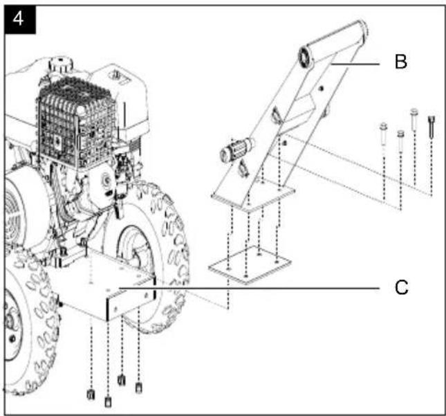
text_image
4 B C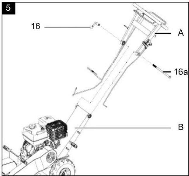
text_image
5 16 A 16a B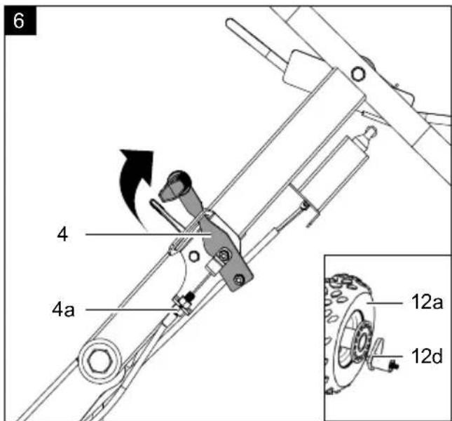
text_image
6 4 4a 12a 12d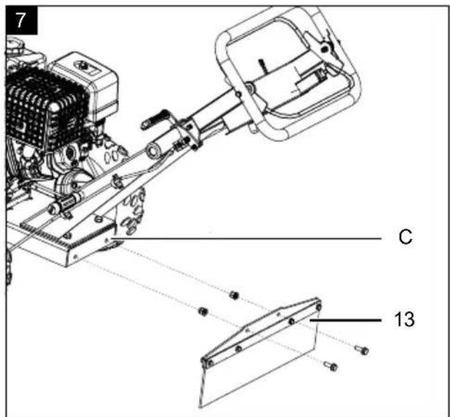
text_image
7 C 13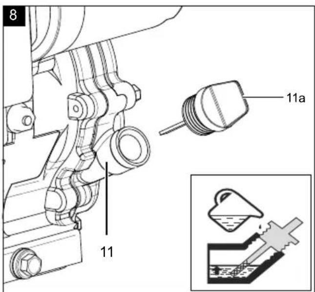
text_image
8 11a 11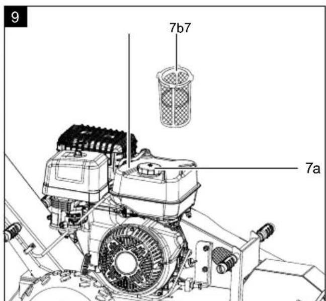
text_image
9 7b7 7a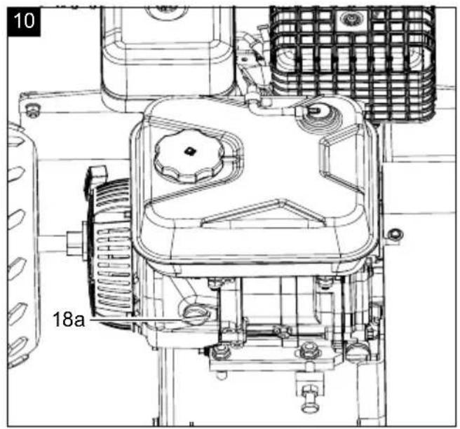
natural_image
Technical line drawing of a mechanical assembly with labeled component '18a' (no readable text or symbols beyond label)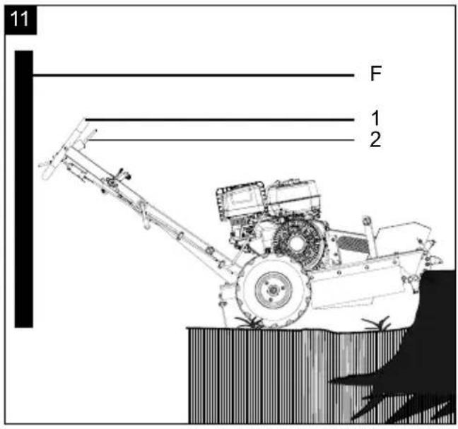
text_image
11 F 1 2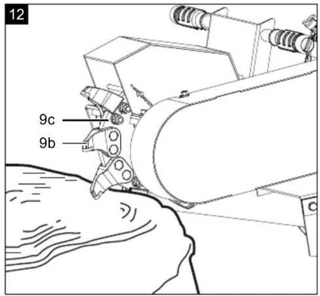
text_image
12 9c 9b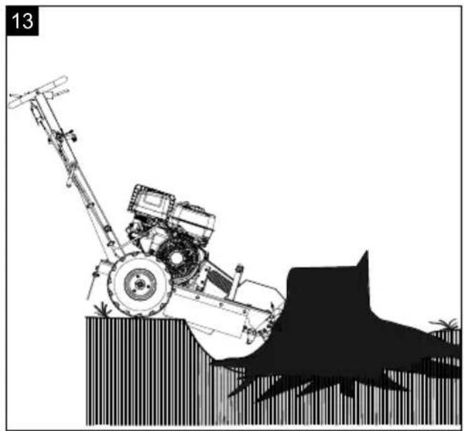
natural_image
Illustration of a tracked agricultural machine with a blade and bucket, shown against a plain background (no text or symbols)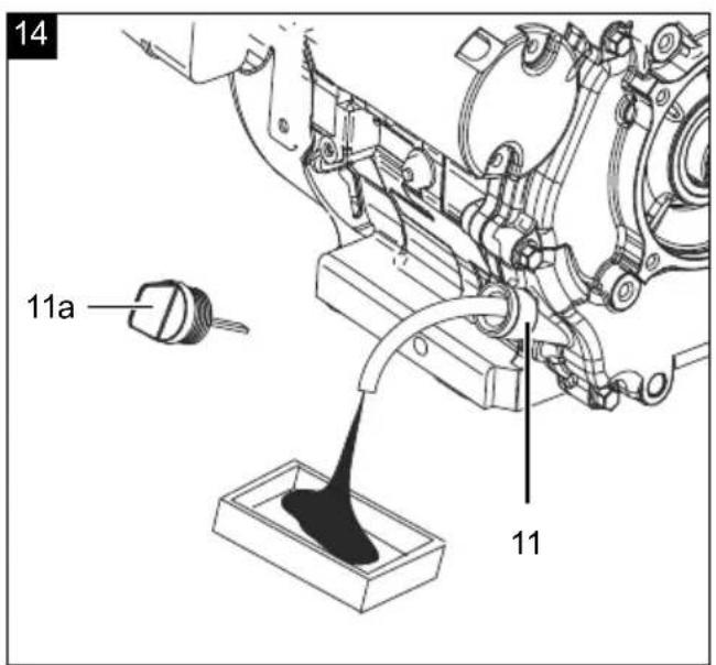
text_image
14 11a 11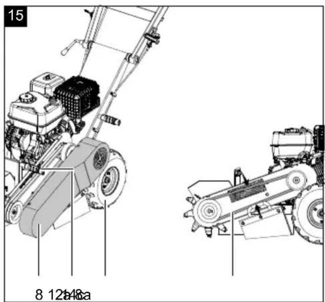
text_image
15 8 12a48a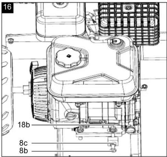
text_image
16 18b 8c 8b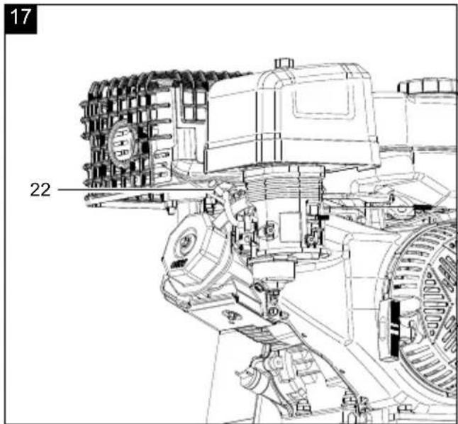
text_image
17 22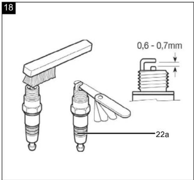
text_image
18 0,6 - 0,7mm 22a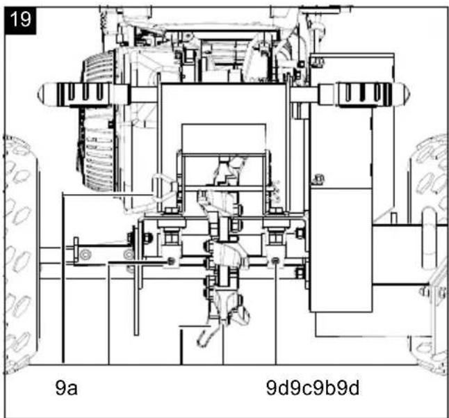
text_image
19 9a 9d9c9b9d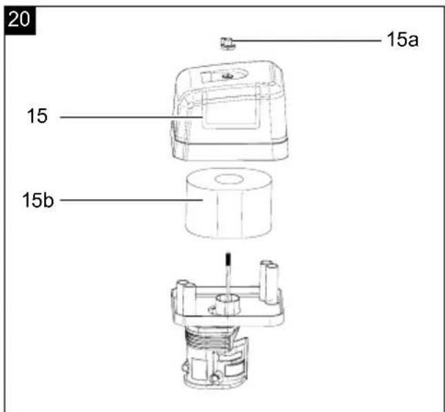
text_image
20 15a 15 15bInhaltsverzeichnis:
Seite:
Günzburger Straße 69
D-89335 Ichenhausen
Hinweis:
• Gabelschlüssel SW 13mm
• Gabelschlüssel SW 18mm
• Gabelschlüssel SW 19mm
Homepage: https://www.scheppach.com/de/service
text_image
https://www.scheppach.com/de/service scheppachTable of contents: Page:
- Explanation of the symbols on the product 32
- Introduction....34
- Proper use 34
- Product description (Fig. 1 - 20)....34
- Scope of delivery 35
- Unpacking 35
- Technical data.... 35
- General safety instructions.... 36
- Assembly 39
- Before commissioning 40
- Operation....41
- Working instructions 43
- Maintenance 43
- Cleaning 47
- Storage 48
- Transport....48
- Repair & ordering spare parts 48
- Disposal and recycling....49
- Troubleshooting 50
- Declaration of conformity 161
1. Explanation of the symbols on the product
Symbols are used in this manual to draw your attention to potential hazards. The safety symbols and the accompanying explanations must be fully understood. The warnings themselves will not rectify a hazard and cannot replace proper accident prevention measures.
 | Attention! Failure to observe the safety signs and warning information affixed to the product and failure to observe the safety and operating manual can result in serious injury or even death. | 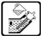 | Check the oil level. |
 | Warning - Read the operating manual to reduce the risk of injury. | 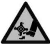 | Danger! Rotating blades.Keep hands and feet outside of the openings when the machine is running. |
 | Wear hearing protection.Exposure to noise can cause hearing loss. | 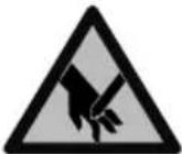 | |
 | Wear safety goggles. Fragments, chippings and dust ejected by the device can case sight loss. | 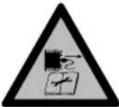 | Remove the spark plug connector prior to all maintenance work. |
 | Wear sturdy footwear! |  | Hurled objects and rotating parts can cause severe injuries. |
 | Wear safety gloves! |  | Important. The exhaust gases are toxic. Do not operate the engine in areas that are not ventilated. |
 | Make sure that other persons maintain a sufficient safety distance. |  | Protect the product from rain and do not leave it outdoors when it rains! |
 | Before commissioning, read and observe the operating manual and safety instructions! |  | Attention: Risk of injury! Do not reach or climb into the feed hopper or ejector chute during operation. |
  | Attention: hot surface - danger of burning.Removing or modifying protective or safety equipment is prohibited. |    | ATTENTION! Operating materials are flammable and explosive.Naked flames are forbidden! Do not refuel while the engine is running! |
 | Important. The exhaust gases are toxic. Do not operate the engine in areas that are not ventilated. |  | Be very careful when handling lubricants! |
 | Weight in kg |  | Clean and replace the air filter according to the specified maintenance interval. |
 | Choke closedOpen the fuel valve |  | Direction of rotation of the milling disc |
 | Tank contents Diameter of the milling dis |  | |
 | Fill with oil before start-up! |  | Milling depth max. |
 | Speed adjustmentHare = fast, MAXTortoise = slow, MIN |  | Milling height max. |
 | Locking brake appliedLocking brake released |  | Guaranteed sound power level of the product |
 | Danger of poisoning! Only use the product outdoors and never in closed or poorly ventilated rooms. |  | Operating materials are flammable and explosive - danger of burning.Do not refuel while the engine is hot or running. |
 | The product complies with the applicable European directives | Δ Attention! | We have marked points in this operating manual that impact your safety with this symbol Δ. |
 | The product complies with the applicable Serbian directives. |
2. Introduction
Manufacturer:
Scheppach GmbH
Günzburger Straße 69
D-89335 Ichenhausen
Note:
In accordance with the applicable product liability laws, the manufacturer of this product assumes no liability for damage to the product or caused by the product arising from:
- Improper handling
- Failure to comply with the operating manual
• Repairs carried out by third parties, unauthorised specialists
• Installing and replacing non-original spare parts - Improper use
Note:
The operating manual is part of this product. It includes important instructions for the safe, proper and economic operation of the product, for avoiding danger, for minimising repair costs and downtimes and for increasing the reliability and extending the service life of the product. In addition to the safety instructions in this operating manual, you must also observe the regulations applicable to the operation of the product in your country. Familiarise yourself with all operating and safety instructions before using the product. Only operate the product as described and for the specified areas of application. Keep the operating manual in a good place and hand over all documents when passing the product on to third parties.
3. Proper use
The petrol stump grinder may only be operated by one person and is intended exclusively for grinding tree stumps and their root systems up to 235 mm lower than the surface of the earth in soil or similar ground. The engine tilt must not exceed 20°.
The product may only be used in the intended manner. Any use beyond this is improper. The user/operator, not the manufacturer, is responsible for damages or injuries of any type resulting from this.
An element of the intended use is also the observance of the safety instructions, as well as the assembly instructions and operating information in the operating manual.
Persons who operate and maintain the product must be familiar with the manual and must be informed about potential dangers.
The liability of the manufacturer and resulting damages are excluded in the event of modifications of the product.
The product may only be operated with original parts and original accessories from the manufacturer.
The safety, operating and maintenance specifications of the manufacturer, as well as the dimensions specified in the technical data, must be observed.
The petrol stump grinder is not too easy to operate:
• in the event of physical and mental unfitness
• without knowledge of the operating manual
• on slopes with a gradient of more than 20^
• on wet or slippery surfaces
• in snow, snowfall and frozen ground
• after dark
- in potentially explosive environments as well as indoors, garages or sheds
• after unauthorised structural alterations or modifications to the product
• after removing safety labels from the product
• after removing or bypassing safety devices
• in the event of damaged cables or milling blades
Please note that our products were not designed with the intention of use for commercial or industrial purposes. We assume no guarantee if the product is used in commercial or industrial applications, or for equivalent work.
The manufacturer is not liable for damage caused by improper use or incorrect operation.
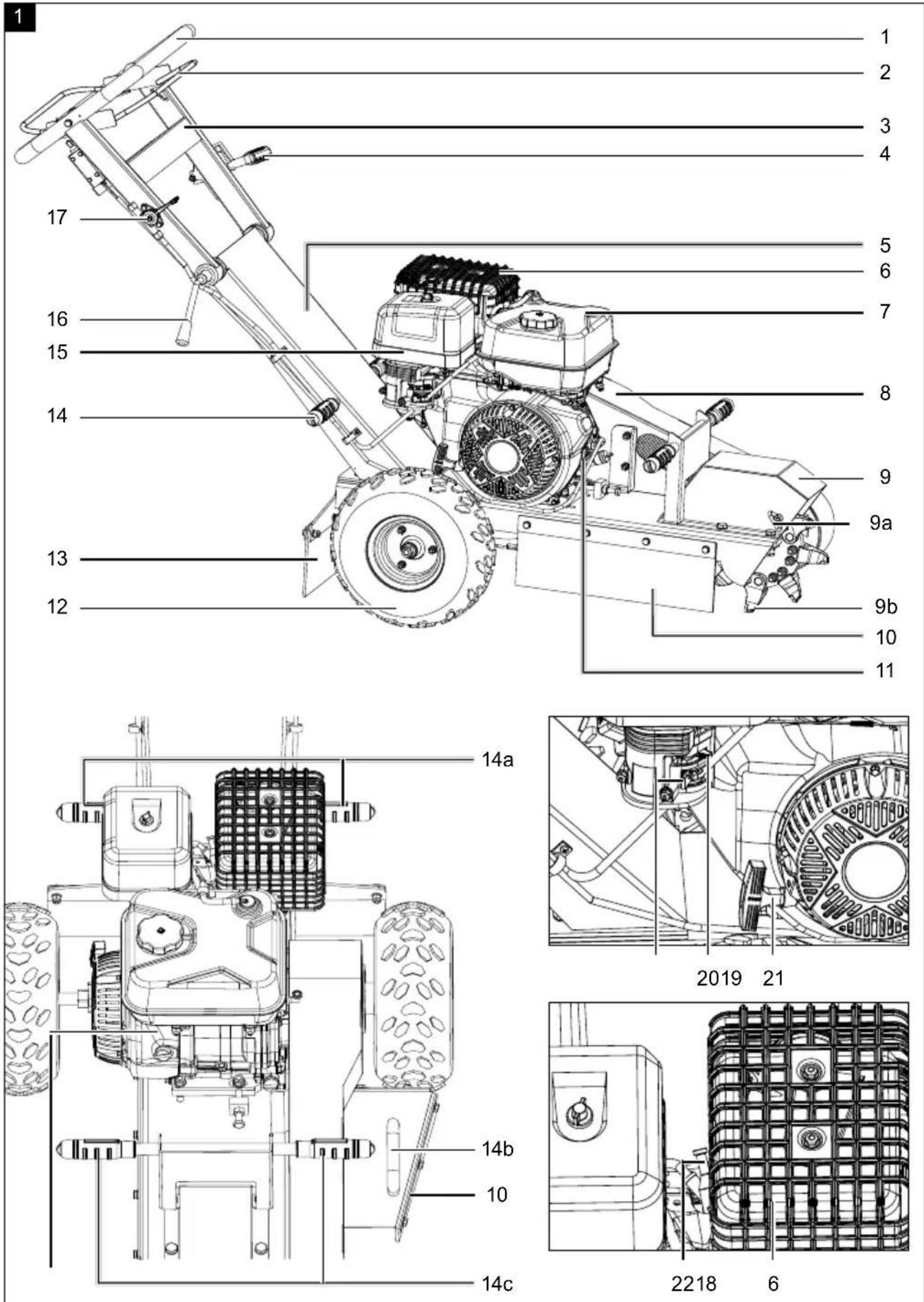
4. Product description (Fig. 1 - 20)
- Handle
- Upper guide rail
- Locking brake
- Lower guide rail
- Exhaust system
- Fuel tank
7a. Fuel filler cap
7b. Fuel filter insert - Belt cover
8a. V-belt
8b. Set screw
8c. Lock nut -
Milling tool cover
-
Emergency stop safety bar
9a. Locking pin
9b. Milling tooth
9c. Milling disc
9d. Grease nipple
10. Side protection mats
11. Engine oil tank
11a. Oil filler cap with oil dipstick
12. Chassis
12a. Wheel with brake disc
12b. Wheel
12c. Wheel axle
13. Rear protective mat
14. Lifting handles
14a. Top lifting handle
14b. Bottom lifting handle
14c. Rear lifting handle
15. Air filter cover
15a. Wing screw
15b. Air filter
16. Locking lever
16a. Fixing screw
17. Throttle
18. Engine
18a. On/off switch
18b. Engine fixing screw
19. Fuel valve
20. Choke lever
21. Pull starter
22. Spark plug connector
22a.Spark plug
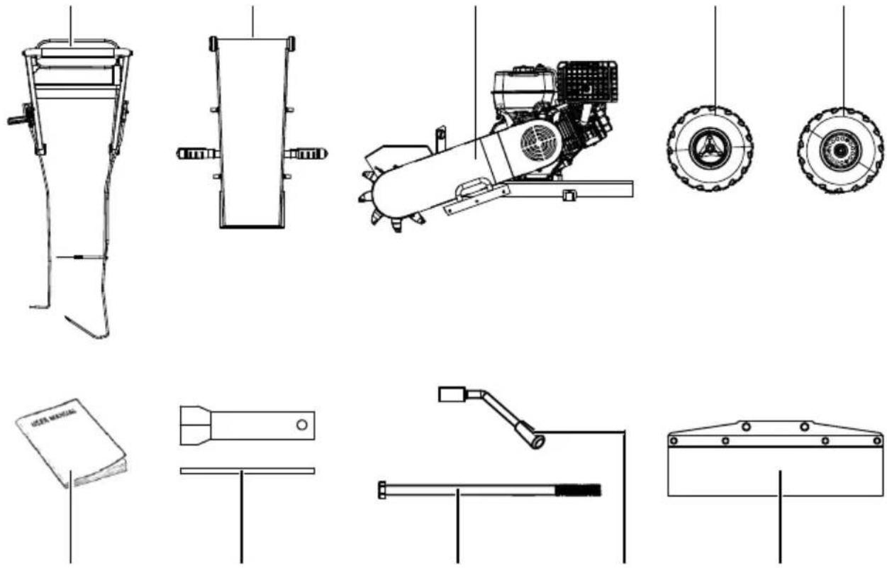
- Scope of delivery
| Item | Quantity | Designation |
| A | 1x | Upper bracket |
| B | 1x | Lower bracket |
| C | 1x | Machine body (wheel axle, 3 side protective mats pre-fitted) |
| 12 a | 1x | Wheel with brake disc |
| 12b | 1x | Wheel |
| 13 | 1x | Rear protective mat |
| 16 | 1x | Locking lever, upper guide rail M16 |
| 16 a | 1x | Fixing screw M16x360 |
| D | 1x | Spark plug wrench |
| E | 1x | Operating manual |
6. Unpacking
⚠ WARNING
The product and the packaging material are not children's toys! Do not let children play with plastic bags, films or small parts! There is a danger of choking or suffocating!
- Open the packaging and carefully remove the product.
- Remove the packaging material, as well as the packaging and transport safety devices (if present).
- Check whether the scope of delivery is complete.
- Check the product and accessory parts for transport damage. In the event of complaints the carrier must be informed immediately. Later claims will not be recognised.
- If possible, keep the packaging until the expiry of the warranty period.
- Familiarise yourself with the product by means of the operating manual before using for the first time.
- With accessories as well as wearing parts and replacement parts use only original parts. Spare parts can be obtained from your specialist dealer.
-
When ordering please provide our article number as well as type and year of manufacture for the product.
-
Technical data
| Drive 1-cylinder, 4-cycle OHV | |
| petrol engine | |
| Displacement 420 ccm^3 | |
| Engine output 9.0 kW | |
| motor speed 3600 rpm | |
| Fuel type Unleaded, min. 95 ROZ (RON), max. 10 % Bioethanol (E10) | |
| Tank capacity - petrol 6.5 l | |
| Recommended engine oil SAE 30 / 10W30 | |
| Engine oil tank capacity 1.1 l | |
| Spark plug type | F7RTC |
| Max. incline | 11 % |
| Starter | Pull starter |
| CO_2 output | 777.93 g/kWh |
| Type of tyres | 145/70-6 |
| Tyre pressure | 1.66 bar |
| Belt tensioning | 30-40 N (1-1.5 cm) |
| Lubricating grease Lithium grease | |
| Milling tool | |
| Number of milling teeth 9 | |
| Max. milling depth (below ground) | 235 mm |
| Max. milling height (above ground) | 600 mm |
| ∅ milling disc 300 mm | |
| Dimensions | |
| Weight (fully assembled and without fuel) | 106 kg |
Subject to technical changes!
Noise and vibration
⚠ Warning: Noise can have serious effects on your health. If the machine noise exceeds 85 dB, please wear suitable hearing protection.
Noise data
| Measured sound power level L_WA | 101.0 dB |
| Guaranteed sound power level L_WA | 103 dB |
| Uncertainty K_WA | 2.14 dB |
| Sound pressure level L_pA | 89.6 dB |
| Uncertainty K_pA | 3 dB |
Vibration parameters
| Vibration a_h | 6.4 m/s ^2 |
| Uncertainty K_h | 1.5 m/s ^2 |
Keep the noise level and vibration to a minimum!
- Only use faultless products.
- Maintain and clean the product at regular intervals.
- Adapt your working methods to the product.
- Do not overload the product.
- Have the product checked if necessary.
- Switch the product off if it is not in use.
- Wear gloves.
⚠ WARNING
In case of extended working periods, the operating personnel may suffer circulatory disturbances in their hands (vibration white finger) due to vibrations.
Raynaud's syndrome is a vascular disease that causes the small blood vessels on the fingers and toes to cramp in spasms. The affected areas are no longer
supplied with sufficient blood and therefore appear extremely pale. The frequent use of vibrating products can cause nerve damage in people whose circulation is impaired (e.g. smokers, diabetics). If you notice unusual adverse effects, stop working immediately and seek medical advice.
Observe the following information to reduce hazards:
- Keep your body and especially your hands warm in cold weather.
• Take regular breaks and move your hands to promote circulation. - Ensure as little vibration as possible of the product via regular maintenance and stable parts on the product.
8. General safety instructions
⚠ WARNING - Read all safety information, instructions, illustrations and technical data for this product.
Failure to follow all instructions listed below may result in electric shock, fire and/or serious injury.
8.1 Explanation of the signal words in the operating manual
DANGER
Signal word to indicate an imminently hazardous situation which, if not avoided, will result in death or serious injury.
⚠ WARNING
Signal word to indicate a potentially hazardous situation which, if not avoided, could result in death or serious injury.
CAUTION
Signal word to indicate a potentially hazardous situation which, if not avoided, could result in minor or moderate injury.
ATTENTION
Signal word to indicate a potentially hazardous situation which, if not avoided, could result in product or property damage.
Save all warnings and instructions for future reference.
⚠ WARNING
Before you start working with the product, familiarise yourself well with all the control parts. The operating manual and labels on the product must be read and understood.
• Find out how and for what purposes the product can be used.
- Deal with the potential hazards of the product.
• Find out how the product is controlled and operated correctly.
- Ensure that the product can be stopped immediately in the event of an emergency.
- Do not attempt to operate the product until you fully understand how to properly operate and maintain the engine and how to prevent accidental injury and/or property damage.
- In the event of an accident or a fault during operation, switch the product off immediately. Treat injuries properly or consult a doctor.
Who is not permitted to use the product:
• The product may only be operated by people who are familiar with handling it.
• Children and young people under the age of 18 are not permitted to work with this product.
• People under the influence of alcohol, drugs and medication, as well as those who are tired or ill.
8.2 Safety at the workplace
- Never start the engine in enclosed spaces or leave it running there. The exhaust gases are dangerous and contain carbon monoxide, an odourless and poisonous gas. Only operate this product in a well-ventilated outdoor area.
- Before each start, ensure that there are no persons or animals in the danger zone ( ≥ 15 m).
-
Only use the product if you have a clear view of the work area and there is sufficient light. Never use the product in conditions of poor visibility (e.g. at dusk or in fog).
-
Never use the product on slippery, unstable or sloping surfaces.
8.3 Personal safety
- Never allow children or other persons who do not know the operating manual to use the product.
- If you give the product to any other person, give them this operating manual as well.
- Wear suitable clothing. Wear long trousers, boots and gloves. Do not wear loose clothing, shorts or jewellery of any kind. Tie up long hair that reaches shoulder length. Always keep hair, clothing and gloves away from moving parts. Loose-fitting clothing, jewellery or long hair may become caught in the moving parts.
-
Wear personal protective equipment to reduce personal injury. These include:
-
Safety goggles,
- Hearing protection,
- safety shoes.
- Cut-resistant clothing
-
Work gloves
-
Check the product before starting. Safety devices must be in their intended location and be in perfect condition. Make sure that all nuts, bolts, etc. are tight.
- Do not operate the product if it needs to be repaired or is not in perfect condition.
- Replace damaged, missing or non-functional parts prior to using the product.
- Check the fuel system for leaks. The product must always be in a safe operating condition.
- Never make any unauthorised changes to the safety devices. Check that they are operating properly on a regular basis.
- The product must not be used if it cannot be switched on or off using the motor switch. Products running on fuel that cannot be controlled using the engine switch are hazardous and must be replaced
- Regularly check that spanners have been removed from the product before starting. Personal injury can result from a spanner left on a rotating part.
- Remain alert and use common sense when operating the product.
- Do not operate the machine barefooted, with sandals or similar light footwear. Wear safety shoes that protect your feet and improve your grip on slippery surfaces.
-
Do not overreach. Keep proper footing and balance at all times. This gives you better control over the product in unexpected situations.
-
Avoid inadvertent starting. Ensure that the motor is switched off prior to transporting the product or carrying out maintenance or servicing work on the product.
- Transporting the product or carrying out maintenance or servicing work on the product while the motor is running can lead to accidents.
- Keep hands and feet away from the moving machine parts.
8.4 Safe handling of fuels ⚠ WARNING
Fuel is highly flammable. Escaping gases are explosive. Fuel tanks may explode when heated:
- Only store fuel in containers (canisters) designed for this purpose.
- Refuel outdoors only and do not smoke while refuelling.
- Fuel must be filled before starting the engine. While the engine is running or immediately after switching off the product, do not open the fuel filler cap or add fuel.
- If fuel overflows, no attempts should be made to start the engine. Instead, the product must be removed from the area contaminated with fuel. Do not try to start the engine until the fuel vapours have evaporated.
- For safety reasons, the fuel tanks and other fuel caps must be replaced if damaged.
- Never store fuel near a source of sparks. Always use a tested canister. Keep fuel away from children.
- Replace defective silencers.
- Prior to use. always perform a visual inspection to check whether the blade and fastening bolts are worn out or damaged. To prevent an imbalance, worn out or damaged blades and bolts may only be replaced in sets.
- Always switch off the engine and let it cool down before refilling the tank. Never remove the tank cover or add fuel while the engine is running or hot. Do not operate the product if the fuel system is leaking.
- Only use the fuel specified in the technical data.
- Do not overfill the tank. Fill with fuel to approximately 1.5 cm below the filler neck to allow space for expansion of the fuel due to heat generated by the engine.
-
Put the tank and container covers back on again tight and wipe off any spilled fuel. Do not operate the product if the fuel tank cap is not fitted.
-
Store the fuel in a cool, well-ventilated place protected from sparks, open flames or other sources of ignition.
- Never store fuel or the product containing a tank filled with fuel in a building where exhaust fumes could come into contact with ignition sparks, open flames or any other ignition source, such as water heaters, ovens, dryers or similar. Allow the engine to cool down before storing the product in enclosed spaces.
8.5 Safety notes on use and care of the product
-
Before starting work, ensure that there are no nails, metal, wires or similar objects in the tree stump and that there are no stones or similar objects on the ground. It is possible that these may become caught or thrown away during milling.
-
Do not start the product until you are near the tree stump.
-
Never pick up the product if the engine is running.
-
Do not operate the product with force.
-
Only carry the product using both hands on the handles provided for this purpose.
-
Use the right product for your application. The right product will perform the task better and more safely.
-
Do not change the settings on the speed control and do not allow the engine to overrev. The speed control controls the maximum safe operating speed of the engine.
-
Avoid contact with hot fuel, oil, flue gases and hot surfaces. Do not touch the engine or silencer. These parts become extremely hot during operation. They also remain hot for a short time after the product has been switched off. Allow the engine to cool before carrying out maintenance or making adjustments.
-
Avoid sudden movements, tilting or jamming the tool.
-
The product is equipped with an emergency stop safety bar. In the event of injury, fire or technical malfunction, stop operation immediately.
-
If the product makes unusual noises or vibrates unusually, switch off the engine immediately, disconnect the ignition cable and look for the cause. Unusual noises or vibrations are generally a warning sign.
-
Only use spare parts and accessories approved by the manufacturer. Failure to comply with this requirement may result in personal injury.
-
Maintain the product. Check whether any parts in motion are misaligned or blocked. Check whether any parts are broken or whether there is any other condition that could affect the operation of the product. If the product is damaged, have it repaired before using it again. Many accidents occur due to inadequately serviced equipment.
- Clear the motor and silencer of grass, leaves, excessive grease or built-up carbon to reduce the risk of fire.
- Always keep cutting tools sharp and clean. Cutting tools with sharp cutting edges that have been properly maintained are less likely to jam and are easier to control.
- Never pour or splash water or any other liquid on the product. Keep handles dry, clean and free of residues. Clean the product thoroughly after each deployment.
- Adhere to laws and regulations concerning the proper disposal of fuel, oil, etc., in order to protect the environment.
- Keep the product out of the reach of children when not in use and do not allow persons unfamiliar with the product or these instructions to operate the product. The product is dangerous in the hands of untrained users.
8.6 Safety instructions for maintenance and repairs
- Switch off the engine before cleaning, repairing, inspecting or adjusting the product. Ensure that all moving parts have been stopped.
- Disconnect the ignition cable and position the cable away from the spark plug to prevent accidental starting.
- Only use manufacturer's recommended accessories and replacement parts. This ensures that the safety of the product is maintained.
- Should the product fail despite our quality controls and your care, only have repairs that are beyond your qualifications and technical capabilities carried out by an authorised specialist workshop.
8.7 Residual risks and protective measures
Neglect of ergonomic principles
Negligent use of personal protective equipment (PPE)
Careless use or omission of personal protective equipment may result in serious injury.
- Wear prescribed protective equipment.
Human behaviour, misconduct
• Always concentrate on all work.
- When you first come into contact with the tree stump, be prepared for the possibility of a significant kick-back.
• Take breaks from work. Prolonged use of the product may cause injuries due to vibrations.
Residual danger
- Can never be ruled out
Danger from noise
Hearing damage
Prolonged unprotected work with the product may cause hearing damage.
• Always wear hearing protection as a matter of principle.
Behaviour in an emergency
In the event of an accident, initiate the necessary first aid measures and seek assistance as quickly as possible .
8.8 Residual risks
The product has been built according to state-of-the-art and the recognised technical safety rules. However, individual residual risks can arise during operation. Furthermore, despite all precautions having been met, some non-obvious residual risks may still remain.
- Residual risks can be minimised if the "Safety Instructions" and the "Intended Use" together with the operating instructions as a whole are observed.
- Use the tool attachment that is recommended in this operating manual. This is how to ensure that your product provides optimum performance.
- Keep your hands away from the working area when the product is in operation.
9. Assembly
CAUTION
Risk of injury from rotating milling tool Only carry out work on the product when the milling tool is switched off and at a standstill!
ATTENTION
Due to the heavy product weight, we recommend that at least three people assemble the product.
- Place the product on a level, even surface.
- Ensure that the safety bar and cable are not broken or damaged by being crushed, pulled or the like.
Required tool:
- Open-ended spanner, size 13 mm
- Open-ended spanner, size 18 mm
- Open-ended spanner, size 19 mm
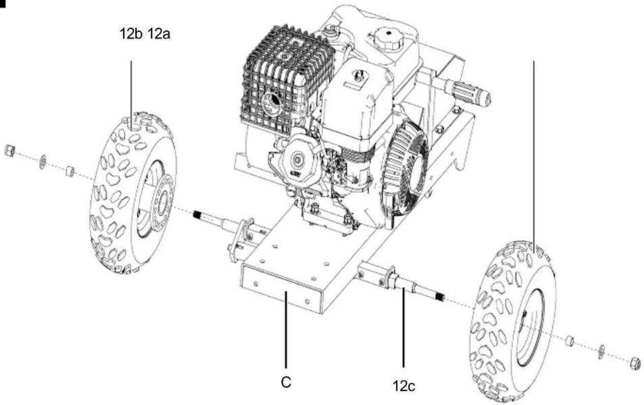
9.1 Fitting the wheels (Fig. 3)
ATTENTION
Risk of damage
Follow the exact steps to ensure a functional product.
- Remove the pre-assembled mounting hardware from the wheel axle (12c).
- Attach the wheel (12a) to the wheel axle (12c) as shown. Use the assembly materials removed in the first step for this purpose.
- Repeat the process with the second wheel (12b).
9.2 Fitting the lower bracket (Fig. 4)
- Remove the pre-assembled mounting material from the machine body (C).
- Attach the lower bracket (B) to the machine body (C) as shown. Use the mounting material that was removed earlier for this purpose.
9.3 Fitting the upper bracket and locking lever (Fig. 5)
- Connect the upper bracket (A) to the lower bracket (B) attached to the machine body (C) as shown.
- Move the upper bracket (A) into the desired position and hold it firmly in place.
- Ask a second person to insert the fixing screw (16a) and the locking lever (16) into the holes provided.
- Now the second person can fix the desired position using the locking lever (16).
9.4 Securing the locking brake Bowden cable (Fig. 6)
- Use the lock nut (4a) to adjust the Bowden cable of the locking brake (4) so that it begins to pull when the parking brake (4) is applied.
- The locking brake (4) must offer noticeable resistance when fully engaged.
- The bolt (12d) on the wheel (12a) must visibly move away from the brake disc when tightened.
9.5 Fitting the rear protective mat (Fig. 7)
- Remove the pre-assembled mounting material from the machine body (C).
- Attach the rear rubber mat (13) to the machine body (C) as shown. Use the assembly materials you removed earlier for this.
10. Before commissioning
ATTENTION
Before starting up the product ensure that it is fully assembled and that the locking pin has been removed!
⚠ WARNING
Health hazard!
Inhalation of fuel / lubricating oil vapours and exhaust gases can cause serious damage to health, unconsciousness and in extreme cases death.
- Do not breathe fuel / lubricating oil vapours and exhaust gases.
- Operate the product outdoors only.
ATTENTION
Product damage!
If the product is operated without or with too little engine oil, this can lead to product damage.
- Fill with fuel and engine oil before commissioning.
The product is delivered without engine oil.
ATTENTION
Environmental damage!
Spilled oil can pollute the environment permanently. The liquid is highly toxic and can quickly lead to water pollution.
- Fill/empty oil only on level, paved surfaces.
- Use a filling nozzle or funnel.
- Collect drained oil in a suitable container.
- Wipe up spilled oil carefully immediately and dispose of the cloth according to local regulations.
- Dispose of oil as per local regulations.
ATTENTION
Risk of damage!
If incorrectly stored or undrained fuel is used, the carburettor may become clogged or engine operation may be affected.
- Put unused fuel in an airtight vessel and store it in a dark, cool room.
Place the product on a level, even surface.
Required tool:
- Funnel*
- Rag/cloth*
* = may not be included in the scope of delivery!
10.1 Filling in engine oil (Fig. 8)
ATTENTION
The product is delivered without engine oil. Therefore, ensure that you add oil before starting it up. Use the engine oil type specified in the technical data .
Check the oil level regularly before commissioning. An oil level that is too low can damage the motor.
- Unscrew the oil filler cap with oil dipstick (11a).
- Fill the engine oil tank (11) using a funnel. Do not exceed the maximum filling level (see Technical Data). Carefully fill the engine oil to the lower edge of the filling nozzle.
- Wipe the oil filler cap with oil dipstick (11a) with a clean, lint-free cloth.
- Screw the oil filler cap with oil dipstick (11a) back into the filling nozzle until it reaches the stop.
- Unscrew the oil filler cap with oil dipstick (11a) and read the oil level in the horizontal position. The oil level must be between L (low) and H (high).
- If the oil level is too low, repeat the process.
- Then screw the oil filler cap with oil dipstick (11a) back in.
10.2 Filling in fuel (Fig. 9)
⚠️ DANGER
Risk of fire and explosion
When filling, fuel may ignite and even explode. This can lead to severe burns or death.
- Switch off the engine and let it cool down.
- Keep heat, flames and sparks away.
- Only fill up with fuel outdoors.
- Wear protective gloves.
- Avoid contact with skin and eyes.
- Start the product at a distance of at least 3 m from the fuel filling point.
- Watch out for leaks. If fuel is leaking, do not start the engine.
- Wipe up spilled fuel immediately and wait until the fuel vapours have dissipated.
ATTENTION
The product is delivered without fuel. It is therefore essential to fill with fuel before commissioning. Use the fuel specified in the technical data for this purpose.
- Clean the area surrounding the filling area. Impurities in the fuel tank (7) lead to operational faults.
-
Carefully open the tank cover (7a) so that any possible overpressure can be relieved.
-
Fill the fuel tank (7) with fuel using a funnel (not included in scope of delivery). Observe the maximum filling quantity specified in the technical data. Carefully fill the fuel up to the lower edge of the filling port.
- Close the fuel filler cap (7a) again. Ensure that the fuel cap is tightly sealed.
- Clean the tank cover (7a) and the surroundings.
11. Operation
ATTENTION
Always make sure the product is fully assembled before commissioning!
ATTENTION
When using products, several safety warnings must be observed to prevent injuries and damage. For this reason, please carefully read this operating manual/ these safety instructions. If you hand the product over to another person, please hand over this operating manual / safety instructions as well. We accept no liability for accidents or damage that occur due to a failure to observe this manual and the safety instructions.
11.1 Check before use (Fig. 1)
⚠ WARNING
Check the safety equipment regularly before each start-up. Faulty safety equipment can cause serious injuries.
- Check that all protective covers (8, 9, 10, 13) are in place and all screws, nuts and bolts are tightened.
- Check that the locking pin has been removed.
- Check all sides of the engine for oil or fuel leaks.
- Check the engine oil level.
- Check the fuel level – the fuel tank should be at least half-full.
- Check the condition of the air filter.
- Check the condition of the fuel lines.
- Make sure that the spark plug connector is attached to the spark plug.
- Look for signs of damage.
11.2 Setting the speed (Fig. 1)
Use the throttle lever (17) to set the engine to the desired speed. There are
- Position: MIN-Tortoise
- Position: MAX-Hare
11.3 Starting engine with a cold engine (Fig. 1, 10) Note:
With high outside temperatures, it may be necessary to start the engine without the choke even when the engine is cold!
- Check the fuel and engine oil level before every start. Make sure that the spark plug connector (22) is connected to the spark plug (22a).
- Set the choke lever (20) to the left to CHOKE.
- Open the fuel tap (19) by setting the lever to ON.
- Set the throttle (17) to "half throttle" (= middle position between MIN- tortoise and MAX- hare).
- Set the on/off switch (18a) to the "ON" position. (Fig. 10)
- Pull the emergency stop safety bar (2) by the handle (1) and hold it.
- Slowly pull out the pull starter (21) until the first resistance is felt.
- Now pull the pull starter (21) and the engine should start. If the engine does not start, repeat the process.
- Allow the engine to warm up briefly. Then slowly open the choke lever (20) to switch to "Normal operation".
- Use the throttle lever (17) to set the speed that is suitable for you.
11.4 Starting engine with a warm engine (Fig. 1, 10)
(The product stood still for less than 15 - 20 minutes.)
-
Check the fuel and engine oil level before every start. Make sure that the spark plug connector (22) is connected to the spark plug (22a).
-
Ensure that the choke lever (20) is set to ON.
-
Open the fuel tap (19) by setting the lever to ON.
-
Set the throttle (17) to "half throttle" (= middle position between MIN- tortoise and MAX- hare).
-
Set the on/off switch (18a) to the "ON" position. (Fig. 10)
-
Pull the emergency stop safety bar (2) by the handle (1) and hold it.
-
Slowly pull out the pull starter (21) until the first resistance is felt.
-
Now pull the pull starter (21) and the engine should start. If the product has still not started after 6 pulls, repeat the process described under 11.3.
-
Use the throttle lever (17) to set the speed that is suitable for you.
11.5 Switch off the engine (Fig. 1, 10) ⚠ WARNING
Danger of injury
After switching the engine off, the milling tool continues to run for a few seconds. If you touch the rotating parts, you may cut yourself.
- Wait until the milling tool comes to a standstill.
- Do not stop the milling tool with your hand.
- Wear protective gloves.
- Keep the milling tool away from your feet.
ATTENTION
Allow the product to run for a short time (approx. 30 seconds) switching it off so that the engine can cool down.
- Use the throttle (17) to set the speed to MIN-Tortoise.
- Release the emergency stop safety bar (2).
- Turn the on/off switch (18a) to OFF. (Fig. 10)
- Wait until the milling tool has come to a complete stop.
- Disconnect the spark plug connector (22) from the spark plug (22a) to prevent the engine from restarting.
- Engage the locking brake (4). To do this, pull the lever backwards.
- Close the fuel tap (19) by setting the lever to OFF.
11.6 Emergency shutdown (Fig. 1, 10) WARNING
Danger to life due to uncontrolled restarting
Uncontrolled restarting can result in serious injury or death.
- Before switching the machine back on, ensure that the cause of the emergency stop has been rectified.
- Ensure that all safety devices are properly installed and in good working order.
- Do not recommence operation of the product until there is no danger to persons.
The emergency stop safety bar (2) prevents the product from starting if the bar is not pressed. This can also be used for emergency shutdown in the following situations:
- when the engine is revving
• if the throttle lever (17) is stuck or not working - in case of danger
In an emergency, proceed as follows:
-
Release the emergency stop safety bar (2). The engine will stop immediately.
-
Engage the locking brake (4). Pull the lever backwards.
-
Before switching the machine back on, eliminate the cause of the emergency stop. If necessary, alert a doctor and the fire brigade and initiate first aid measures.
-
Switch off the on/off switch (18a, Fig. 10) and secure the product against being switched on again.
11.7 Automatic oil cut-off (Fig. 10)
Note:
The automatic oil cut-off system responds when there is too little engine oil.
-
If the oil level is too low, top up the oil as described in 10.1.
-
Press the on/off switch (18a) as described in 11.5.
12. Working instructions
⚠ WARNING
Risk of injury from rotating components
- Keep hands, feet and clothing away from moving parts of the product (drive belts, milling tools, etc.).
⚠ WARNING
Risk of injury and damage from flying parts
Loose items can become caught in the machine and fly out in any direction. They can also bounce off other objects and injure people or damage property.
- Remove stones, roots, wires, etc. from the work area.
- Ensure that bystanders keep a sufficient distance.
- Work with the utmost caution.
⚠ WARNING
Risk of burns from hot surfaces
- Wear protective clothing and gloves when working near hot construction and engine parts.
CAUTION
Risk of cuts on the milling tool due to sharp edges and pointed corners
- Always proceed with caution when working near sharp edges and pointed corners.
- Wear protective gloves.
12.1 Operator position (Fig. 11)
-
Stand behind the product while working. (F, Fig. 11)
-
Ensure that you can always reach the handle (1) and the emergency stop safety bar (2), as the emergency stop safety bar (2) must be pulled during the entire milling process.
-
Ensure that the surface is safe and level and that there is sufficient distance from people and obstacles. Keep unauthorised persons away.
12.2 Removing tree stumps (Figs. 6, 12–13)
-
Carefully move the stump grinder to the designated work site.
-
Observe the requirements for operator position under 12.1.
-
Check the machine in accordance with the information in 11.1 of the operating machine. Ensure that all safety-related components are functioning properly and that there is no visible damage.
-
Start the engine according to the instructions in 11.3 or 11.4.
-
Apply the locking brake (4) and then accelerate to full throttle to reach the optimum operating speed.
-
Now start with the milling work. Tilt the product onto the chassis (12) so that the entire milling tool with milling disc (9c) and milling teeth (9b) is lifted off the tree stump surface. (Fig. 12)
-
Guide the cutter from left to right until the desired depth is reached. Ensure that you move the tool evenly and avoid removing too much material in a single pass. (Fig. 13)
-
Excess material may accumulate during work. Always switch off the machine before removing the material to avoid injury. Then carefully remove the material before continuing with the work.
-
Once you have finished milling, switch off the stump grinder as described in 11.5 and allow it to cool down completely. Afterwards, the stump grinder should be thoroughly cleaned to remove dirt, chips and residues. Only then can the machine be stored safely and dry.
13. Maintenance
⚠ WARNING
In the event that the user is to perform maintenance and service work, the user must possess the necessary technical skills.
If the product is shut down for maintenance, inspection or storage, turn off the engine, disconnect the spark plug connector from the spark plug and ensure that all rotating parts have stopped.
Secure the product to prevent an inadvertent start-up before carrying out maintenance and/or servicing work:
- Switch off the engine before carrying out any cleaning or maintenance work.
- Allow the motor to cool down.
-
Remove the spark plug connector (22) from the spark plug (22a).
-
Regular, careful servicing is required to guarantee the safety level and performance of the product.
- Ensure that all nuts, pins and screws are securely tightened so that the product is in a safe working condition.
- Check the product regularly for signs of wear and loss of functionality.
- For safety reasons, replace worn or damaged parts.
- Use only original spare parts.
- Check that the wheels (6) are secured .
- Any work not described in this operating manual must be performed by an authorised specialist workshop only.
13.1 Changing the oil (Fig. 1, 14)
⚠ WARNING
Health hazard!
Inhalation of fuel / lubricating oil vapours and exhaust gases can cause serious damage to health, unconsciousness and in extreme cases death.
- Do not breathe fuel / lubricating oil vapours and exhaust gases.
- Operate the product outdoors only.
ATTENTION
Product damage!
If the product is operated without or with too little engine oil, this can lead to product damage.
- Fill with fuel and oil before commissioning. The product is delivered without engine oil.
ATTENTION
Environmental damage!
Spilled oil can pollute the environment permanently. The liquid is highly toxic and can quickly lead to water pollution.
- Fill/empty oil only on level, paved surfaces.
- Use a filling nozzle or funnel.
- Collect drained oil in a suitable container.
- Wipe up spilled oil carefully immediately and dispose of the cloth according to local regulations.
- Dispose of oil as per local regulations.
Change the engine oil after 100 operating hours.
The engine oil change should be carried out while the engine is at operating temperature.
- Place the product on a level, even surface.
- Remove the spark plug connector (22) from the spark plug (22a). (Fig. 1)
- Unscrew the oil dipstick (11a).
- Now use an oil pump to pump the old oil out of the engine oil tank (11) through the opening of the oil filler plug (11a).
- Fill with new engine oil (for type and quantity, see technical data).
- Wipe the oil dipstick (11a) with a clean, lint-free cloth.
- Screw the oil dipstick (11a) back into the filler neck until it reaches the stop.
- Screw the oil dipstick (11a) out and read the oil level in the horizontal position. The oil level must be between L (low) and H (high).
- If the oil level is too low, top up the oil as described in section 9.1.
- Dispose of the used oil properly.
Dispose of the used oil in accordance with applicable regulations.
13.2 Checking the oil level (Fig. 1, 14)
NOTE!
Product damage
If the product is operated without or with too little engine oil, this can lead to product damage.
- Fill with petrol and oil before commissioning. The product is delivered without engine oil.
- Only use the fuel specified in the technical data.
- Only use the engine oil specified in the technical data.
NOTE!
Environmental damage!
Spilled oil can pollute the environment permanently. The liquid is highly toxic and can quickly lead to water pollution.
- Fill/empty oil only on level, paved surfaces.
- Use a filling nozzle or funnel.
-
Collect drained oil in a suitable container.
-
Wipe up spilled oil carefully immediately and dispose of the cloth according to local regulations.
-
Dispose of oil as per local regulations.
-
Place the product on a level, even surface.
- Remove the spark plug connector (22) from the spark plug (22a). (Fig. 1)
- Unscrew the oil filler cap with oil dipstick (11a).
- Wipe the oil filler cap with oil dipstick (11a) with a clean, lint-free cloth.
- Screw the oil filler cap with oil dipstick (11a) back into the filling nozzle until it reaches the stop.
- Unscrew the oil filler cap with oil dipstick (11a) and read the oil level in the horizontal position. The oil level must be between L (low) and H (high) on the oil filler cap with oil dipstick (11a).
- If the oil level is too low, top up the oil as described in section 9.1.
- Then screw the oil filler cap with oil dipstick (23) back on.
13.3 Draining petrol with a petrol extraction pump\* (Fig. 1, 9)
In the case of storage over a longer period of time, the petrol must be drained.
- Place the product on a level, even surface.
- Remove the spark plug connector (22) from the spark plug (22a). (Fig. 1)
- Hold a collection bucket under the hose on the petrol extraction pump.
- Unscrew and remove the fuel filler cap (7a).
- Remove the fuel filter insert (7b).
- Push the petrol extraction pump's hose into the fuel tank (7) and drain the petrol completely using the petrol extraction pump.
- Reinsert the fuel filter insert (7b).
- Retighten the fuel filler cap (7a).
*may not be included in the scope of delivery
13.4 Checking and replacing the V-belt
Remove the belt cover (8) to gain access to the V-belt (8a). Never use the product without the belt cover (8). If the belt cover (8) is not in place, it is possible that your hand will be caught between the V-belt and the clutch, causing you serious injury.
13.4.1 Tensioning the V-belts (Fig. 1, 15, 16)
The V-belt (8a) must be in good condition to ensure optimum power transmission from the engine to the eccentric shaft.
Check the condition of the V-belt.
- Switch off the engine (18) and let it cool down. (Fig. 1)
- Place the product on a level, even surface.
- Remove the spark plug connector (22) from the spark plug (22a).
- Support the chassis (12) with wooden blocks, for example, and secure it against rolling away.
- Loosen and remove the wheel with the brake disc (12a).
- Remove the belt cover (8) by unscrewing the four hexagonal bolts using a 10 mm open-ended spanner. (Fig. 15)
- Now check the belt tension (thumb pressure). If the V-belt (8a) gives more than 10-15 mm (thumb pressure), you must retighten it.
- To do this, slightly loosen the four motor fixing screws (18b) on the motor and push the motor forward towards the lifting handles (14c). (Fig. 15, 16)
- Now loosen the two counternuts (8c).
- Tighten the V-belt (8a) using the adjusting screw (8b) if the V-belt (8a) gives more than 10-15 mm (thumb pressure). To do this, turn the adjusting screw (8b) clockwise. Make sure that the engine and pulley remain at a right angle.
- After tensioning, retighten the four engine fixing screws (18b) and the counternuts (8c).
- Re-attach the belt cover (8) and secure it with four hexagonal bolts.
- Fit the wheel with the brake disc (12a). When installing, ensure that the fixing parts are assembled in the correct order.
- Remove all the parts you needed to support it underneath.
13.4.2 Replacing the V-belt (Fig. 1, 15, 16)
If the V-belt (8a) is torn, worn out or smooth, it must be replaced.
- Switch off the engine (18) and let it cool down. (Fig. 1)
- Place the product on a level, even surface.
- Remove the spark plug connector (22) from the spark plug (22a).
- Support the chassis (12) with wooden blocks, for example, and secure it against rolling away.
- Loosen and remove the wheel with the brake disc (12a).
-
Remove the belt cover (8) by unscrewing the four hexagonal bolts using a 10 mm open-ended spanner. (Fig. 15)
-
Then slightly loosen the four engine fixing screws (18b) on the engine. (Fig. 16)
- To release the tension on the V-belt (8a), open the lock nut (8c) and turn the adjusting screw (8b) anti-clockwise.
- Push the motor towards the lifting handles (14c). (Fig. 15)
- Pull the worn V-belts (8a) off the pulleys and fit the new V-belts correctly.
- Tighten the V-belt (8a) using the adjusting screw (8b) if the V-belt (8a) gives more than 10-15 mm (thumb pressure). To do this, turn the adjusting screw (8b) clockwise. Make sure that the engine and pulley remain at a right angle. (Fig. 16)
- After tensioning, retighten the four engine fixing screws (18b) and the counternuts (8c).
- Re-attach the belt cover (8) and secure it with four hexagonal bolts.
- Fit the wheel with the brake disc (12a). When installing, ensure that the fixing parts are assembled in the correct order.
- Remove all the parts you needed to support it underneath.
13.5 Maintaining the spark plug (22a) (Fig. 17, 18)
Check the spark plug (22a) for contamination for the first time after 20 operating hours and clean it with a copper wire brush if necessary. Then maintain the spark plug (22a) every 50 operating hours.
- Place the product on a level, even surface.
- Remove the spark plug connector (22) from the spark plug (22a).
- Remove the spark plug (22a) with the spark plug wrench (D).
- Remove any dirt from the base of the spark plug (22a).
- Visually inspect the spark plug (22a). Remove any deposits present using a copper wire brush.
- Check the spark plug gap. Use a feeler gauge to adjust the electrode gap to 0.6-0.7 mm.
- Refit the spark plug (22a) and take care not to overtighten it.
- Then place the spark plug connector (22) on the spark plug (22a).
ATTENTION
When you remove or attach the V-belt (8a), make sure that your fingers do not get caught between the belt and the pulley.
13.6 Greasing grease nipples (Fig. 17-19)
- Place the product on a level, even surface.
- Remove the spark plug connector (22) from the spark plug (22a).
- Secure the milling disc (9c) using the locking pin (9a).
- Remove the protective caps from the grease nipples (9a) on both sides.
- Use a lint-free cloth to clean the grease nipples (9d) on both sides.
- Use 1-2 pumps of the grease nipples to lubricate the bearings (9d) on both sides.
- Use a lint-free cloth to clean the grease nipples (9d) on both sides to remove excess grease.
- Fit the protective caps to the grease nipples (9d) on both sides.
13.7 Changing the milling tool (Fig. 19)
- Place the product on a flat and stable surface.
- Secure the product against rolling away and accidental starting.
- Insert the locking pin (9a) to secure the tool.
- Loosen the two nuts (AF16 mm) and then remove the two screws (AF16 mm).
- Replace the milling tooth (9b).
- Now refit the two screws (AF16 mm) and secure them with the two nuts (AF16 mm).
13.8 Maintenance plan
| Task: | Before every use | Every 25 operating hours | every 50 operating hours | Annually or every 100 operating hours |
| Replace the spark plug X | ||||
| Change the engine oil X | ||||
| Checking the oil level X | ||||
| Tightening/checking screws (milling disc) | X | |||
| Check milling tool for damage and wear X | ||||
| Check the air filter X | ||||
| Check the braking system | X | |||
| Tyre pressure | X | |||
| Grease the grease nipples | X | |||
| Checking the emergency stop safety bar | X | |||
| Check belt tension | X | |||
| Check the fuel quantity | X |
14. Cleaning
⚠ WARNING
Risk of injury from starting machine
- Always switch off the engine and disconnect the spark plug connector before making any adjustments to the product.
-
Allow the product to cool
-
Keep protective devices, air vents and the motor housing as free of dust and dirt as possible. Rub the product clean with a clean cloth or blow it off with compressed air at low pressure.
• We recommend that you clean the product directly after every use. - Clean the product at regular intervals using a damp cloth and a little soft soap. Do not use any cleaning products or solvents; they could attack the plastic parts of the product. Make sure that no water can penetrate the interior of the product.
⚠ WARNING
Never use a high-pressure cleaner to clean your product.
The use of high-pressure cleaners shortens the service life and reduces the ease of maintenance.
⚠ WARNING
Improper maintenance or cleaning work can cause injuries
⚠ WARNING
The product may start unexpectedly and cause injuries and burns during cleaning, repair and maintenance work.
- Switch the product off.
- Remove the spark plug connectors (22) from the spark plug (22a).
- Allow the product to cool down.
14.1 Cleaning the V-belt (8a) (Fig 1, 15)
- Place the product on a level, even surface.
- Remove the spark plug connector (22) from the spark plug (22a).
- Support the chassis (12) with wooden blocks, for example, and secure it against rolling away.
- Loosen and remove the wheel with the brake disc (12a).
- Remove the belt cover (8) by unscrewing the four hexagonal bolts using a 10 mm open-ended spanner.
-
Clean the transmission elements and the two V-belts (8a) once to twice per year using a brush or compressed air.
-
Re-attach the belt cover (8) and secure it with four hexagonal bolts.
- Fit the wheel with the brake disc (12a). When installing, ensure that the fixing parts are assembled in the correct order.
- Remove all the parts you needed to support it underneath.
14.2 Cleaning the fuel filter insert (7b) (Fig. 9)
Note: The petrol filter insert (7b) is a fuel filter insert cup, which is located directly under the fuel cap (7a) and filters all the fuel that is filled in.
-
Screw the tank cover (7a) on.
-
Remove the fuel filter insert (7b). Do not clean it in a flammable solvent or a solvent with a high flash point.
-
Reinsert the fuel filter insert (7b).
-
Retighten the fuel filler cap (7).
14.3 Clean the air filter (Fig. 20)
- Remove the wing screw (15a) from the air filter cover (15).
- Lift off the air filter cover (15).
- Remove the air filter (15b) and tap it gently to remove dust and dirt.
- Refit all parts in reverse order.
Note: If the air filter is heavily soiled or damaged, it should be replaced.
15. Storage
15.1 Preparation for storage
⚠ WARNING
Do not remove the fuel in enclosed spaces, near fire or when smoking.
Petrol fumes can cause explosions and fire. If the product will not be used for a period of more than 30 days, the following measures must be taken to prepare it for storage.
- Clean and check the product for damage.
• Empty the fuel tank using a petrol extraction pump. - Start the engine and let it run until the remaining fuel is used up.
- Store fuel in tanks specifically designed for this purpose.
- Change the oil at the end of every season.
- Remove the spark plug connector from the spark plug.
- Store the product in a well-ventilated place or area.
15.2 Storing the product
- Store the product and its accessories in a dark, dry and frost-free place that is inaccessible to children.
- The optimum storage temperature lies between 5 and 30^ .
- Store product in the original packaging.
• Cover the product to protect it from dust or moisture. - Store the operating manual with the product.
16. Transport
⚠ WARNING
Danger to life when lifting and transporting
Falling loads or parts thereof can kill people.
- Only use lifting and transport equipment, as well as mechanical stops, holders and safety devices in perfect condition to lift the product.
- Before transport, ensure that the load is securely fastened.
- Never stand under a raised load.
- Wear a safety helmet.
16.1 Preparing for transport (Fig. 1)
- Place the product on a level surface.
- Close the fuel tap (19).
- Insert the locking pin (9a).
- Empty the fuel tank (7) with a petrol extraction pump (not necessarily included in the scope of delivery).
Warning: Do not remove the petrol in enclosed spaces, near fire or when smoking. Petrol fumes can cause explosions and fire. - Remove the spark plug connector (22) from the spark plug (22a).
- Clean the product.
16.2 Transporting the product (Fig. 1)
• The product can be transported on a van or trailer.
- The product is equipped with lifting handles (14a, 14b, 14c) that can be used both for lifting the machine and for securing it.
- Due to its weight, the product should only be lifted using suitable equipment or by several people working together.
17. Repair & ordering spare parts
After repairs or maintenance, make sure that all safety-related parts are installed and are in perfect condition. All parts which may cause injury must be kept where they are inaccessible to children or others.
Attention: According to the German Product Liability Act, no liability is accepted for damage caused by improper repairs or by not using original spare parts.
Such work should be performed by a customer service centre or an authorised specialist. The same applies to accessory parts.
Spare parts and accessories can be obtained from our Service Centre. To do this, scan the QR code on the front page.
Connections and repairs
Connections and repair work on the electrical equipment may only be carried out by electricians.
Please provide the following information in the event of any queries:
• Type of current for the motor
• Machine data - type plate
- Motor data - type plate
Important note in the case of repairs:
For return delivery of the product for repair, please ensure for safety reasons that it is free of oil and fuel when it is sent to the service centre.
17.1 Ordering spare parts
Please provide the following information when ordering spare parts:
- Model designation
- Item number
- Type plate data
17.2 Service information
With this product, it is necessary to note that the following parts are subject to natural or usage-related wear, or that the following parts are required as consumables.
Wearing parts*: Wheels, V-belts, spark plugs, air filters, protective mats, milling teeth
* may not be included in the scope of delivery!
18. Disposal and recycling
Notes for packaging


The packaging materials are recyclable. Please dispose of packaging in an environmentally friendly manner.
You can find out how to dispose of the disused product from your local authority or city administration.
Fuels and oils
- Before disposing of the device, the fuel tank and the engine oil tank must be emptied!
- Fuel and engine oil do not belong in household waste or drains, but must be collected or disposed of separately!
- Empty oil and fuel tanks must be disposed of in an environmentally friendly manner.
19. Troubleshooting
The following table shows fault symptoms and describes remedial measures in the event of your product failing to work properly. If you cannot localise and rectify the problem with this, please contact your service workshop.
WARNING
Risk of injury and danger to life when the engine is running due to hot surfaces and rotating parts
- Switch off the product before you start troubleshooting.
- Disconnect the spark plug connector from the spark plug to prevent the engine from restarting.
| Fault Possible cause Remedy | ||
| Engine does not start | No fuel | Fill the fuel tank |
| Pull starter defective Repair or replace | the pull starter | |
| No engine oil Fill with engine oil | ||
| No ignition spark Clean or replace the | spark plug | |
| Engine cold and choke set to RUN | Engine cold and choke set to CHOKE | |
| Fuel tap set to OFF Set the fuel tap to | ON | |
| Engine gets too hot | Not enough engine oil Refill the engine oil | |
| Air filter dirty Clean or replace air filter | ||
| Carburettor incorrectly adjusted | Repair by an authorised service centre | |
| Reduced power | Milling tool blunt Change milling tool | |
| V-belt worn out Replace V-belt | ||
| V-belt slips | Tension V-belt | |
| Excessive vibration | Screws/nuts loose | Switch off the engine immediately! Check that screws/nuts are tight and retighten if necessary |
| moving parts damaged | Switch off the engine immediately! Repair by an authorised service centre | |
Table des matières: Page:
Günzburger Straße 69
D-89335 Ichenhausen
Remarque :
- Position: MIN-Tortue
- Position : MAX-Lièvre
Günzburger Straße 69
D-89335 Ichenhausen, Germania
Indicazione:
Günzburger Straße 69
D-89335 Ichenhausen
Aanwijzing:
Günzburger Straße 69
13.6 Engrase del engrasador (figs. 17-19)
Günzburger Straße 69
9.1 Montar as rodas (fig. 3)
ATENÇÃO
Risco de danos
text_image
Technical diagram of a mechanical assembly with numbered components and labeled parts in Chinese
text_image
Exploded view diagram of a mechanical assembly with labeled components and exploded viewsScheppach GmbH, Günzburger Str. 69, 89335 Ichenhausen
| DE | EU-KonformitätserklärungOriginalkonformitätserklärungWir erklären in alleiniger Verantwortung, dass das hier beschriebene Produkt mit den geltenden Richtlinien und Normen übereinstimmt. | Der hier beschriebene Gegenstand der Erklärung erfüllt die Vorschriften der Richtlinie 2011/65/EU des Europäischen Parlaments und des Rates vom 8. Juni 2011 zur Beschränkung der Verwendung bestimmter gefährlicher Stoffe in Elektro- und Elektronikgeräten.*Technische Unterlagen verfügbar bei: ** | ||
| Artikelnummer*** | Artikelbezeichnung: Benzin-Baumstumpffräse SGM4200 | Marke**** | ||
| GB | EU Declaration of ConformityTranslation of the original Declaration of ConformityWe declare under our sole responsibility that the product described here complies with the applicable directives and standards. | The object of the declaration described here fulfils the regulations of the directive 2011/65/EU of the European Parliament and Council from 8th June 2011, on the restriction of the use of certain hazardous substances in electrical and electronic equipment.*Technical documentation available at: ** | ||
| Item number*** | Item designation: Petrol stump grinder SGM4200 | Brand**** | ||
| FR | Déclaration UE de conformitéTraduction de la déclaration de conformité originaleNous déclarons, sous notre propre responsabilité, que le produit décrit ici est conforme aux directives et normes en vigueur. | L'appareil décrit ci-dessus dans la déclaration est conforme aux réglementations de la directive 2011/65/EU du Parlement Européen et du Conseil du 8 juin 2011 visant à limiter l'utilisation de substances dangereuses dans la fabrication des appareils électriques et électroniques.*Dossier technique auprès de:** | ||
| Référence *** | Désignation de l'article: Broyeuse de souche thermique SGM4200 | Marque **** | ||
| IT | Dichiarazione di conformità UETraduzione della dichiarazione di conformità originaleDichiariamo sotto la nostra esclusiva responsabilità che il prodotto qui descritto è conforme alle direttive e alle norme vigenti. | L'oggetto della dichiarazione, qui descritto, soddisfa le disposizioni della Direttiva 2011/65/UE del Parlamento Europeo e del Consiglio dell'8 giugno 2011, sulla restrizione nell'utilizzo di determinate sostanze pericolose negli apparecchi elettrici ed elettronici.*Documentazione tecnica disponibile presso: ** | ||
| Gaminio numeris *** | Nome articolo: Fresaceppl a benzina SGM4200 | Marchio **** | ||
| NL | EU-conformiteitsverklaringVertaling van de originele conformiteitsverklaringWij verklaren onder eigen verantwoordelijkheid dat het hier beschreven product voldoet aan de geldende richtlijnen en normen. | Het hier beschreven onderwerp van deze verklaring voldoet aan de voorschriften van richtlijn 2011/65/EU van het Europese Parlement en de Raad van 8 juni 2011 omtrent de beperking van het gebruik van bepaalde gevaarlijke stoffen in elektrische en elektronische apparaten.*Technische documentatie verkrijgbaar bij: ** | ||
| Artikelnummer *** | Artikelnaam: Benzine boomstronkfrees SGM4200 | Merk **** | ||
| ES | Declaración de conformidad UETraducción de la Declaración de conformidad originalDeclaramos, bajo nuestra exclusiva responsabilidad, que el producto aquí descrito cumple las directivas y normas aplicables. | El objeto de la declaración aquí descrito cumple las disposiciones de la Directiva 2011/65/UE del Parlamento Europeo y el Consejo del 8 de junio de 2011 sobre restricciones a la utilización de determinadas sustancias peligosas en aparatos eléctricos y electrónicos.*Documentación técnica disponible en:** | ||
| Núm. de artículo*** | Denominación del artículo: Desbastadora de tocones a gasolina SGM4200 | Marca**** | ||
| PT | Declaração de conformidade UETradução da declaração de conformidade originalDeclaramos, à nossa exclusiva responsabilidade, que o produto aqui descrito está em conformidade com as diretivas e normas aplicáveis. | O objeto da declaração aqui descrito cumpre com as normas da Diretiva 2011/65/UE do Parlamento Europeu e do Conselho de 8 de junho de 2011 relativamente à restrição da utilização de determinadas substâncias perigosas em equipamentos elétricos e eletrónicos.*Documentos técnicos disponíveis junto de:** | ||
| Número de artigo*** | Designação do artigo: Moedor de cotos a gasolina SGM4200 | Marca**** | ||
| CZ | EU prohlásení o shoděPřeklad originálního prohlásení o shoděProhlašujeme na svou výlučnou odpovědnost, že zde popsaný výrobek od-povídá platným směrnicím a normám. | Zde popsany předmět prohlásení splňuje předpisy směrnice 2011/65/EU Evrop-ského parlamentu a Rady ze dne 8. června 2011 pro omezení používání určitých nebezpečných látek v elektrických a elektronických zařízeních.*Technické podklady k dispozici u:** | ||
| Číslo výrobku*** | Název výrobku: Benzínová fréza na pařezy SGM4200 | Značka**** | ||
| SK | EÚ vyhlásenie o zhodePreklad originálneho vyhlásenia o zhodeNa vlastnú zodpovednosť vyhlasujeme, že tu popísaný výrobok je v súlade s platnými smernicami a normami. | Tu oplsaný predmet vyhlásenia je v súlade s predpismi smernice Európskeho parlamentu a Rady 2011/65/EÚ z 8. júna 2011 o obmedzení používania určitých nebezpečných látok v elektrických a elektronických zariadeniach.*Technické podklady sú k dispozícii na:** | ||
| Číslo výrobku *** | Označenie výrobku: Benzínová fréza na pne SGM4200 | Značka **** | ||
| HU | EU megfelelőségi nyilatkozatAz eredeti megfelelőségi nyilatkozat fordításaSaját kizárólagos felelősségünkre kijelentjük, hogy az itt ismertetett termék megfelel az érvényes irányelveknek és szabványoknak. | A nyilatkozat itt megnevezett tárgya teljesíti az Európai Parlament és Tanács 2011. június 8-i, egyes veszélyes anyagok elektromos és elektronikus berendezésekben való alkalmazásának korlátozásáról szóló 2011/65/EU irányelvének előírásait.*A műszaki dokumentáció elérhető:** | ||
| Cikkszám *** | Termék megnevezése: Benzines tuskómaró SGM4200 | Márka **** | ||
| PL | Deklaracja zgodności UETłumaczenie oryginalnej deklaracji zgodnościOświadczamy na własną odpowiedzialność, że opisany tutaj produkt jest zgodny z obowiązującymi dyrektywami i normami. | Wymieniony powyżej przedmiot niniejszej deklaracji jest zgodny z wymogami dyrektywy 2011/65/UE Parlamentu Europejskiego i Rady z 8 czerwca 2011 r. w sprawie ograniczenia stosowania niektórych niebezpiecznych substancji w sprzęcie elektrycznym i elektronicznym.*Dokumentacja techniczna dostępna na stronie:** | ||
| Numer artykułu *** | Nazwa artykułu: Benzynowa frezarka do pni SGM4200 | Marka **** | ||
| HR | EU izjava o sukladnostiPrijevod originalne izjave o sukladnostiNa svoju odgovornost izjavljujemo da je ovdje opisan proizvod usklađen s važećim direktivama i normama. | Ovdje opisani predmet Izjave ispunjava propise Direktive 2011/65/EU Europskog parlamenta i Vijeća od 8. lipnja 2011. o ograničenju uporabe određenih opasnih tvari u električnoj i elektroničkoj opremi.*Tehnička dokumentacija dostupna je na:** | ||
| Broj artikla*** | Naziv artikla: Benzinska freza za panjeve SGM4200 | Marka**** | ||
| SI | EU izjava o skladnostiPrevod originalne izjave o skladnostiS polno odgovornostjo izjavljamo, da je tukaj opisani izdelek v skladu z ve- ljavnimi smernicami in standardi. | Tukaj opisani predmet izjave izpolnjuje predpise Direktive 2011/65/EU Evropskega parlamenta in Sveta z dne 8. junij 2011 za omejevanje uporabe določenih nevarnih snovi v električnih in elektronskih napravah.*Tehnični dokumenti so na voljo pri:** | ||
| Številka izdelka *** | Opis izdelka: Bencinski rezalnik za drevesne štore SGM4200 | Znamka **** | ||
| EE | EL vastavusdeklaratsioonVastavusdeklaratsiooni originaali tõlgeMe deklareerimine ainuisikuliselt vastutades, et siin kirjeldatud toode ühtib esilatud direktiivide ja normidega. | Deklaratsiooni objektiks olev siin kirjeldatud ese vastab Euroopa Parlamendi ja nõukogu direktiivile 2011/65/EÜ kuupäevaga 8. juuni 2011 teatud ohtlike ainete kasutamispiirangu kohta elektri- ja elektroonikaseadmetes.*Tehnilised dokumentid on saadaval:** | ||
| Artiklinumber *** | Art nimetus: Bensilni-puutüvefrees SGM4200 | Kaubamärk **** | ||
| LT | EB atitikties deklaracijaAtitikties deklaracijos originalo vertimasPrisiimdami išskirtinę atsakomybę deklaruojame, kad čia aprašytas gaminys atitinka galiojančias direktyvas ir standartiem. | Čia aprašytas deklaracijos objektas atitinka 2011 m. birželio 8 d. Europos Parlamento ir Tarybos direktyvos 2011/65/ES dél tam tikrų pavojingų medžiagų naudojimo elektros ir elektroninėje jrangoje apribojimo reikalavimus.*Techninius dokumentus galima gauti iš:** | ||
| Gaminio numeris *** | Gaminio pavadinimas: Benzininė kelmų freza SGM4200 | Prekės ženklas **** | ||
| LV | ES atbilstības deklarācijaOriginālās atbilstības deklarācijas tulkojumsMės, uzņemoties pilnu atbildību, pazinojam, ka šeit aprakstītais ražojums atbilst spēkā esošajām direktiivām un standartiem. | Šeit aprakstītais deklarācijas priekšmets atbilst Eiropas Parlamenta un Eiropas Padomes 2011. gada 8. jūnija Direktīvas 2011/65/ES notekumiem par noteiktu bīs-tamo vielu izmantošanas ierobežošanu elektriskajās un elektroniskajās iericės.*Tehniskā lieta ir pieejama pie:** | ||
| Preces numurs *** | Preces apzīmējums: Benzīna celmu frēze SGM4200 | Prečzīme **** | ||
| SE | EU-försākran om överensstämmelseÖversättning från försākran om överensstämmelse i originalVi förklarar under eget ansvar att produkten som beskrivs här överensstämm-mer med gällande riktlinjer och standarder. | Föremälet för försākran som beskrivs här överensstämmer med bestämmelserna i Europaparlamentets och rădets direktiv 2011/65/EU av den 8 juni 2011 om be-gränsning av användningen av vissa farliga ämnen i elektriska och elektroniska produkter.*Teknisk dokumentation tillgänglig hos:** | ||
| Artikelnummer *** | Artikelbeteckning: Bensindriven stubbfräs SGM4200 | Märke **** | ||
| FI | EU-vaatimustenmukaisuusvakuutusAlkuperäisen vaatimustenmukaisuusvakuutuksen käännösVakuutamme omalla vastuullamme, että tãssä kuvattu tuote täyttää voimas-sa olevien direktiivien ja standardien määräykset. | Tässä kuvattu vakuutuksen kohde täyttää tiettyjen vaarallisten aineiden käytön rajoittamisesta sähkö- ja elektronikkalaitleissa 8. kesäkuuta 2011 annetun Euroo-pan parlamentin ja neuvoston direktiivin 2011/65/EU määräykset.*Tekniset asiakirjat saatavana:** | ||
| Tuotenro *** | Tuotenimike: Bensiinikäyttöinen kantojyrsin SGM4200 | Merkki **** | ||
| DK | EU-overensstemmelseserklæringOversættelse af den originale overensstemmelseserklæringVi erklærer under eget ansvar, at det her beskrevne produkt overholder de gældende direktiver og standarder. | Genstanden for den her beskrevne erklaering overholder bestemmelserne i Europa-Parlamentets og Rădets direktiv 2011/65/EU af 8. juni 2011 vedr. begrænsning af brugen af visse farlige stoffer i elektrisk og elektronisk udstyr.*Tekniske dokumenter findes på:** | ||
| Artikelnummer *** | Art.-betegnelse: Benzindrevet træstubfræser SGM4200 | Mærke **** | ||
| NO | EU-samsvarserklæringOversettelse av den opprinnelige samsvarserklæringenVi erklærer med eneansvar at produktet som er beskrevet her er i samsvar med gjeldende direktiver og standarder. | Gjenstand for erklæringen beskrevet her oppfyller forskriftene til direktiv 2011/65/EU fra Europa-Parlamentet og Rădet av 8. juni 2011 om begrensning av bruken av bestemle farlige stoffer i elektronikk og elektronisk utstyr.*Tekniske dokumenter tilgjengelig hos:** | ||
| Artikkelnummer *** | Art.betegnelse: Bensindreven trestubbefres SGM4200 | Merke **** | ||
| BG | ЕС Декларация за съответствиеПревод на оригиналната декларация насъответствиеНие декларираме на своя отговорност, че описаният тук продукт отговаря на приложимите директиви и стандарти. | Описаният предмет в декларацията отговаря на разпоредбите на Дирек-тива 2011/65/ЕС на Европейския парламент и на Съвета от 8 юни 2011 г.относно ограничението на употребата на определени опасни вещества велектрическото и електронното оборудване.*Техническата документация се предоставя от:* | ||
| Каталожен номер *** | Обозначение на артикула: Бензинова фреза за дънери SGM4200 | Марка **** | ||
| GR | Дήλωση συμμόρφωσης EEMетафраση από το πρωτότυπο της δήλωσης συμμόρφωσηςΔηλώνουψε με αποκλειστική μας ευδύνη ότι το προϊόν που περιγράφεταιστο παρόν βρίσκεται σε συμμόρφωση με τις ισχύουσες Οδηγίες και Πρό-тutta. | Το αντικείμενο της παρούσας δήλωσης, το οποϊο περιγράφεται εδώ, εκτιληρώνειτις διατάξεις της Οδηγίας 2011/65/ΕΕ του Ευρωπαϊκού Κοινοβουλίου και του Συμβουλίου της 8ης Ιουνίου 2011 σχετικά με τον περιορισμό της χρήσης ορισμένωνεπτικίνδυνων ουσιών σε ηλεκτρικό και ηλεκτρονικό εξοπλισμό.*Ο τεχνικός φάκελος είναι διαθέσιμος στη θέση:* | ||
| Αριθμός είδους *** | Ονομασία προϊόντος: Βενζινοκίνητη φρέζα ισοπέδωσης κορμών SGM4200 | Μάρκα **** | ||
| RO | Declaratie de conformitate UETraducere a declarației de conformitate originaleDeclarăm pe proprie răspundere că produsul descris aici coincide cu direc-tivele și normele în vigoare. | Obiectul declarației descris aici îndeplinește prescripțiile directivei 2011/65/UE aParlamentului European și a Consiliului din 8 lunie 2011 asupra limitării utilizăriianumitor substanțe periculoase în aparatele electrice și electronice.*Documentație tehnică disponibilă la:* | ||
| Număr articol *** | Denumirea articolului: Freză pe benzină pentru cioturi de copac SGM4200 | Marcă **** | ||
| RS | EU izjava o usaglašenostiPrevod originalne izjave o usklađenostitizjavljujemo na našu isključivu odgovornost da je ovde opisani proizvod usk-lađen sa primenljivim smernicama i standardima. | Ovde opisani predmet ove izjave ispunjava odredbe Direktive 2011/65/EU Evrops-kog parlamenta i Saveta od 8. juna 2011. godine o ograničenju upotrebe određenihopasnih materija u električnoj i elektronskoj opremi.*Tehnička dokumentacija dostupna kod:* | ||
| Broj artikla *** | Oznaka proizvoda: Benzinska freza za panjeve SGM4200 | Brend **** | ||
| TR | AB uygunluk beyaniOrijinal uygunluk beyanının çevirisiBurada açıklanan ürünün geçerli yönetmelikdere ve standartlara uygun oldu-gunu tamamen kendi sorumluluğumuz altında beyan ediyoruz. | İşbu uygunluk beyanının düzenlendiği burada adı geçen ürün, Avrupa Parlamen-tosu’nun ve 8 Haziran 2011 tarihli Konsey’in elektrik ve elektronik cihazlarda belirlitehlikeli maddelerin sınırlandırılmasına ilişkin 2011/65/AT sayılı direktifini yerinegetirmektedir.*Teknik belgeler şurada mevcuttur:* | ||
| Ürün numarası *** | Ürün Tanım: Benzinli ağaç kütüğü frezesi SGM4200 | Marka **** | ||
| ***5904905903 | ****SCHEPPACH | |||
**:Stefan HartingerGünzburger Str. 69D-89335 Ichenhausen i. V. Andreas Pecher /Head of Project Management i. V. Andreas Pecher /Head of Project Management i.V. Simon Schunk /Division Manager Product CenterIchenhausen, 06.03.2026 i.V. Simon Schunk /Division Manager Product CenterIchenhausen, 06.03.2026 | 2011/65/EU*2014/30/EU2014/29/EU2014/35/EU2004/22/EG2014/68/EU89/686/EWG_96/58/EG90/396/EWG2023/826/EU | 2006/42/EGAnnex IVNotified Body:Notified Body No.:Certificate No.: | 2000/14/EG_2005/88/EGNoise:measured L_WA = 101.0 dBguaranteed L_WA = 103 dB(A)Annex VAnnex VINotified Body:Notified Body No.: | |
| 2016/1628/EU | Emission No.: e13*2016/1628*2017/656SRB1/P*0075*00 | |||
| EN ISO 4254-1:2015/A1:2021; EN ISO 12100:2010 | ||||