
CAM360AHDHD - Rear Camera DOMETIC - Free user manual and instructions
Find the device manual for free CAM360AHDHD DOMETIC in PDF.

| Product Type | Rear View Camera |
| Brand | Dometic |
| Model | CAM360AHDHD |
| Category | 360° Rear View Camera System |
| Operating Voltage | 12 V DC (range 10-16 V) |
| Operating Current | ~1 A / 12 V |
| Operating Temperature | -20 °C to +70 °C |
| Maximum Video Resolution | 1920x1080p |
| Camera Viewing Angle | 180° |
| Number of Cameras | 4 (front, rear, left, right) |
| Display Mode | 360° panoramic view, 2D/3D modes, bird's-eye view |
| Video Recording | Yes, on SD card (max 128 GB), circular buffer |
| Pedestrian Detection | Yes, integrated ADAS function |
| Remote Control | Included with numeric and navigation keys |
| Connectivity | Trigger inputs (turn signals, reverse), universal video output |
| Warranty | Legal warranty |
| Maintenance and Cleaning | Clean the cameras with a soft dry cloth. Avoid solvents. |
| Safety | Do not open the camera. Follow assembly and wiring instructions. |
| Spare Parts and Repairability | Spare parts available: cables, brackets, O-rings. Repair by qualified personnel. |
Frequently Asked Questions - CAM360AHDHD DOMETIC
User questions about CAM360AHDHD DOMETIC
0 question about this device. Answer the ones you know or ask your own.
Ask a new question about this device
Download the instructions for your Rear Camera in PDF format for free! Find your manual CAM360AHDHD - DOMETIC and take your electronic device back in hand. On this page are published all the documents necessary for the use of your device. CAM360AHDHD by DOMETIC.
USER MANUAL CAM360AHDHD DOMETIC
natural_image
Technical line drawing of a remote control unit, a remote device with ports, and a rectangular electronic device (no text or symbols)CAM360AHDHD
360° camera system
Installation and Operating Manual......T
360° Kamerasystem
Montage- und Bedienungsanleitung...... VQ
Système de caméra à 360°
Instructions de montage et de service..... YJ
Sistema de cámara de 360°
Instrucciones de montaje y de uso......QQZ
Slovenia de Camara de 300
Instruções de montagem e manual de instruções.... QKY
Istruzioni di montaggio e d'uso...... QZX
See camera system
Montagehandleiding en gebruik saanwijzing...| TW
DA 300 - Kaimlerasystem
Monterings- og betjeningsvejledning..... | XK
300 Kamerasystem
Monterings- och bru sanvisning......T00
N/ 300 Kaimerasystem
Monterings- og bru sanvisning...... TVX
2014
" sennus- ja äyttöohje...... TYT
T
Instru cja monta%u i obsługi...... VQZ
360 kallef, -. system
' (vod na mont() a uvedenie do prev(dz y.... VKY
500 Kaimler, . system
' (vod mont() i a obsluze...... VZW
III 500, S. Kumetare, auser
Szerel+si +s haszn( lati , tmutat- ...... KTT
\0.5 - \ 1.55 - \$ 2.55
. pute za monta) u i ru ovanje...... KXJ
3.00
Montaj ve /ullanəm /əlavuzu....WJ W
-
' avodila zalmonta) o in uporabo......WVI
1. 2017年1月1日
Manual de instalare 2i de utilizare...... WXY
450765. 67 K. 5695 J. 500 35110A
34567689:76 ;<и>9:<л<циА и В<С6:<.....X0К
500 KuahkerasDstech
Daigaldus- ja asutusjuhend....XKV
2007.10.20
Εγχειρίδιο τοποθέτησης και χρήσης......ΧΖ away
1. 2017年1月1日
Montavimo ir naudojimo vadovas...... YTQ
3.00 Námerlas Sistema
. zstEdFGanas un lietoGanas ro asgrEmata...... YWY
C, DyriEFt
H I J I K L ometic Mroup. Nhe visual appearance o the contents o this manual is protected by copyright and design law. Nhe underlying technical design and the products contained herein may be protected by design patent or pending patent. Nhe trademarks mentioned in this manual belong to L ometic Sweden " B. " ll rights are reserved.
E) ElisF
Q Important notes....T
I RSplanation o0 symbols....T
T Uelated documents....V
V Safety instructions....V
K Scope o0 delivery....W
W "cessories....X
X Intended use....X
Y Technical description....X
Z Installation.....QX
QJ Operation....| Z
QQ Nroubleshooting.... TY
Q1 Warranty....TY
QT Lisposal....TZ
QV Technical data....TZ
G ImD, rta) t), tes
Please read these instructions carefully and follow all instructions ^p guidelines ^p and warnings included in this product manual in order to ensure that you install use ^p and maintain the product properly at all times. These instructions M. SN stay with this product.
By using the product ^p you hereby confirm that you have read all instructions ^p guidelines ^p and warnings carefully and that you understand and agree to abide by the terms and conditions as set forth herein. You agree to use this product only for the intended purpose and application and in accordance with the instructions ^p guidelines ^p and warnings as set forth in this product manual as well as in accordance with all applicable laws and regulations. " Failure to read and follow the instructions and warnings set forth herein may result in an injury to yourself and others ^p damage to your product or damage to other property in the vicinity. This product manual ^p including the instructions ^p guidelines ^p and warnings ^p and related documentation ^p may be subject to changes and updates. For up-to-date product information ^p please visit documents.dometic.com.
H EI Dla) ati,) , J symK, ls
" signal word will identify safety messages and property damage messages ^p and also will indicate the degree or level of hazard seriousness.

DAN3 ERL
Indicates a hazardous situation that ^P i0 not avoided ^P will result in death or serious injury.

MARNIN3L
Indicates a hazardous situation that ^p iC not avoided ^p could result in death or serious injury.

CAU! I( NL
Indicates a hazardous situation that ^P i ^C not avoided ^P could result in minor or moderate injury.

N(!ICEL
Indicates a situation that ^P iC not avoided ^P can result in property damage.

N(!E Supplementary information for operating the product.
3 Related d, c1me) ts

Find more information on operation in the configuration guide at _r.dometic.com/beaeYa.
Failure to obey these warnings will result in death or serious injury.
Nhe camera does not release the driver from the duty of care when driving.
Nhe driver remains fully responsible or driving the vehicleP or fulfilling the road safety obligationsP and or complying with the statutory road safety requirements.

MARNIN3L Risk, J i) j1 ry
Failure to obey these warnings could result in death or serious injury.
This camera can be used by children aged from Y years and above and persons with reduced physical sensory or mental capabilities or lac o0 eSperience and knowledge i0 they have been given supervision or instruction concerning use of the device in a safe way and understand the hazards involved.
Secure the parts installed in the vehicle in such a way that they cannot become loose under any circumstances bsudden bra ing ^p accidents and cause injuries to the occupants of the vehicle.
L o not install parts anywhere in the vehicle where an airbag may open. This can cause injury i0 the airbag deploys.
Inade_uate supply line connections can result in short circuits causing
e f able fires
e Nhe airbag being triggered
e Lamage to electronic control devices
e R Electrical malfunctions turn signal ^P stoplight ^P horn ^P ignition ^P lightsc

CAU! I( NL Risk, J i) j1 ry
Failure to obey these cautions could result in minor or moderate injury.

Secure any parts of the system concealed by the bodywor in such a manner that they cannot become loose or damage other parts or cables or impair vehicle functions steering pedals etc.c.
" Iways follow the safety instructions of the vehicle manufacturer. Some wor be.g.P on retention systems such as the airbagP etc.c may only be performed by _ualified specialists.
N(!ICEL DamaEe Fa0ard
No prevent damage when drilling ensure that there is sufficient space on the other side for the drill head to emerge.
L eburr all drill holes and treat them with a rust-protection agent.
When working on the electrical system ^P the batteries must be separated from the vehicle ground. This applies to the main and additional batteries.
When working on the following cables only use insulated cable lugs ^P plugs and tab sleeves of TJ direct input from positive battery terminalc
e QK connected positive terminal behind the battery
e TQ return cable from the batteryP ground
e KY breversing lightc
L o ), t use porcelain wire connectors.
. se a crimping tool to connect the cables.
Screw the cable when connecting cable TQ bgroundc.
e Screw the cable using a cable lug and loc washer to one of the vehicles ground bolts or
e Screw the cable to the sheet metal body wor using a cable lug and a sel0-tapping screw.
Rnsure that there is a good ground connection.
I0 the battery is disconnectedP all data stored in all volatile memory will be lost. L ata may have to be reset. Follow the instructions o0 the vehicle manu0acturer in this case. Nhe instructions or ma ing these settings can be found in the operating manual.
When testing the voltage in electrical cables only use a diode test lamp or a voltmeter. Nest lamps with a bulb consume too much voltage which can damage the vehicles electronic system.
When ma ing electrical connections ensure the following
e Nhey are not in ed or twisted.
e Nhey do not rub on edges.
e Nhey are not laid in sharp-edged through-holes without protection.
Insulate all connections.
Secure the cables against mechanical stress with cable binders or insulating tape ^P e.g. to eSisting lines.
Follow the installation and operating manual for the monitor.
L o not open the camera.
L o not pull the cables.
L o not eSpose the cables to solvents such as benzene 0 or long periods of time.
L o not use the cameras under water.
Install cables Qar enough away Qrom hot or moving vehicle parts beShaust pipesP drive shai s eShaust pipesP drive shai sP lightsP blowersP heatersP etc.c.
QPG Sc, De, J deli-ery
□
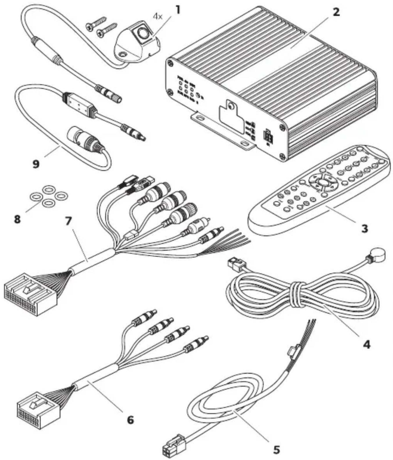
| N, P C, mD, ) e) t R 1a) tity |
| Q f amera V |
| I f ontroller Q |
| T Uemote control Q |
| V IU receiver Q |
| K aehicle connection cable Q |
| W f onnecting harness or the camera cables Q |
| X . niversal connection cable Q |
| Y O-rings V |
| Z Monitor connection cable Q |
QPH Access, ries
" vailable as accessories bnot included in the scope of deliverycd
| C, mD, ) e) t ReJP ), P | |
| f alibration set V mats ZWI J J QTI TJ |
6 I) te) ded 1 se
Nhe camera system is intended for use in vehicles. Nhe cameras transmit images in a TWJ j panoramic view that provides a view of the vehicle's environment to the sides in front and behind.
Nhe camera system is used to monitor the immediate surroundings o ^0 the vehicle ^p e.g ^p when driving ^p changing lanes ^p maneuvering ^p or par ing. Nhe display o ^0 the camera image is determined by trigger signals.
This product is only suitable for the intended purpose and application in accordance with these instructions.
This manual provides information that is necessary for proper installation and/or operation of the product. Door installation and/or improper operation or maintenance will result in unsatisfactory performance and a possible failure.
Nhe manufacturer accepts no liability or any injury or damage to the product resulting from
e Incorrect installation ^p assembly or connection ^p including eScess voltage
e Incorrect maintenance or use of spare parts other than original spare parts provided by the manufacturer
e "Iterations to the product without eSpress permission from the manufacturer
e. se for purposes other than those described in this manual
L ometic reserves the right to change product appearance and product specifications.
Nhe camera system consists of our QZJ j wide angle cameras that are located on the Front the rear the lei and the right sides of the vehicle. Nhe video system displays a vehicle graphic on the connected monitor screen which can be customized. "video processor merges the recorded images into a TWJ j panoramic view that shows the vehicles surroundings. Nhe camera system can display the camera images in I L P T L P or combined. Nhe I L view displays the camera images in a high-angle-shot. Rach camera image is displayed separately. Nhe TL view displays the camera images as combined surround view or separately in the fish-eye or birds-eye view. Nhe V cameras create a virtual camera that moves around the vehicle depending on the settings made and trigger signals.
Nhe camera system is e_uipped with a pedestrian detection function in the camera image overlap areas at the corners of the vehicle to support the safety level.
Nhe camera system is switched when the vehicle is started.
L epending on the settings single cameras can be activated by trigger signals ^P e.g. ^P by using a turn signal or reverse gear.
Nhe control unit okers several Functions such as
e " permanent split screen or a split screen triggered by a control signal
e "utomatic bull screen mode for the reversing camera as a rear mirror function
e " permanent cull screen mode or the TWJ 1j panorama view
aideos from the cameras can be saved according to the circular buker principle and played bac within the camera system. When a recording se_ uence endsP the neSt recording se_ uence starts automatically. Nhe duration of the recording se_ uence can be adjusted. Once the memory is 0ullP the oldest file is overwritten automatically.
aideos can be played bac on a L ometic monitor ^p an eSternal monitor ^p or via a computer using the SL cards. No play videos on a computer ^p the SL card cover on the controller must be easily accessible and the I .I WV video Cormat must be supported by the computer.
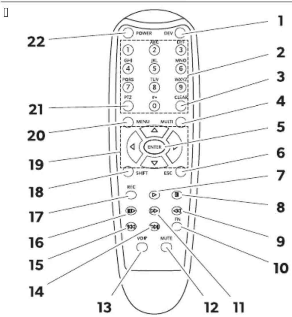
SPG Rem, te c,) tr, l
| N, P 21tt,) DescriDti,) | ||
| Q | DEV | ' o function. |
| I J m Z | e Switches between the camera modes in the main interface depending on the default view set.e Selects various menu options in the main menu.e Rnter the corresponding numbers that are written on the buttons. | |
| T | CLEAR | L eletes the last entered number letter or character selected. |
| V | MULTI | Switches to the birds-eye view in the main interface. Only one camera image is displayed. |
| K | ENTER | Opens the main menu or confirms the selected menu selection. |
| W | ESC | RSits the main menu or returns to the main menu. |
| X | [AA8Z] | o function. |
| Y | [AA93] | |
| Z | [BOCC] | |
| QJ | [246H] | |
| [CTOT] | ||
| QI |  | |
| QT | [KT7B] | |
| QV | [2XTT] | |
| QK |  | |
| QW | [CE4A] | |
| QX | [WS30] | |
| QY | SHIFT | e L isplays the Quad mode bsee f amera modes on pageLOWc.e Opens or closes the main menu.e Switches through the settings and configurations in some windows. |
| QZ |  | e Opens the surround view in the main interface and rotates the camera view to the lei b or right b c and switches it to the rear b c or front b c.e Switches through the settings and configurations in some windows. |
| [DDOK] | ||
| [TXWY] | ||
| [SSXD] | ||
| I J | MENU | o function. |
| I Q | PTZ | Rnters a decimal point. |
| I I | POWER | Switches the camera system on and ok.Nhis function is bloc ed in the login interface menus and settings. |
The following icons are displayed in the top right-hand corner of the main interface when they have been activated.
| lc,) DescriDti,) | |
| Nhe MDS signal is good. | |
| Nhe MDS signal is average. | |
| Nhe MDS signal is poor. | |
| ' o MDS signal is detected. | |
| " n nash drive is connected and operating. | |
| ' o nash drive is detected. | |
| Nhe connected nash drive is not wor ing properly. | |
| " n SL card is connected and operating. | |
| ' o SL card is detected. | |
| Nhe connected SL card is not wor ing properly. | |
| Nhe camera system records the displayed camera imagesc. | |
| Nhe camera image o0 the front camera is displayed to the lei o0 the arrow. | |
| Nhe camera image o0 the right camera is displayed to the lei o0 the arrow. | |
| Nhe camera image o0 the rear view camera is displayed to the lei o0 the arrow. | |
| Nhe camera image o0 the lei camera is displayed to the lei o0 the arrow. | |
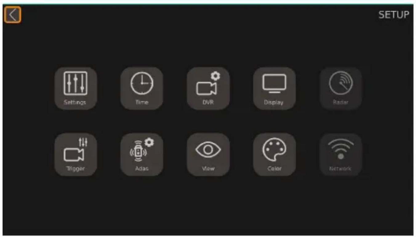
Nhe main menu can be divided into W categories.
| Feat1re DescriDti,) | |
| Guidance | f ontains guides for performing calibration setting the surround view and time "das b" dvanced L rivers "ssistant Systemp and LaU bL igital aideo Uecorderc. |
| Setup | f ontains general settings for the I L /TL view the screen ratio or combined views and setting or activate and deactivate functions. |
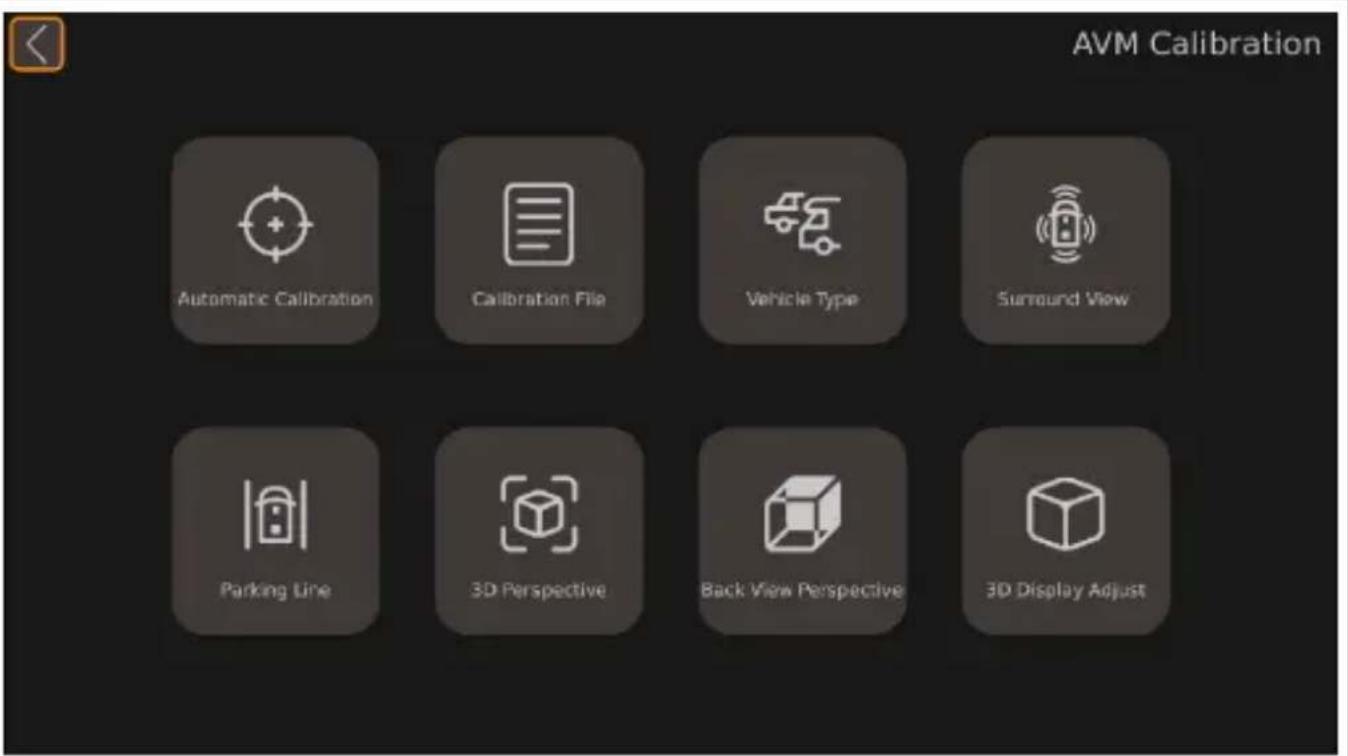
| AVM | " ll " round aiew Monitor system b" aMcf ontains the settings for calibration vehicle model change view settings par ing line and image resolution. |
| Storage f ontains information about the storage management. | |
| Video f ontains the recording management for checking and eSporting videos. | |
| Info f ontains the information data about the version of the f D. and Mf . . | |
Guidance
Nhe video system has an guidance function that guides the user through the most important settings and eSplains them with animated images.
□
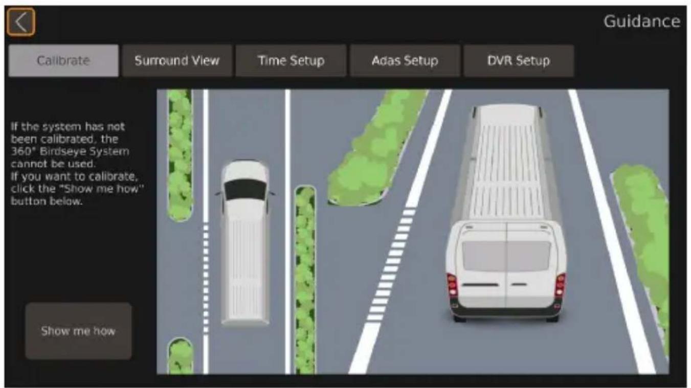
| Feat1re DescriDti,) | |
| Calibrate f ontains the guide 0or calibrating the camera system. | |
| Surround View f ontains the guide 0or setting the surround view. | |
| Time Setup f ontains the guide 0or setting the time. | |
| Adas Setup f ontains the guide 0or the pedestrian detection system. | |
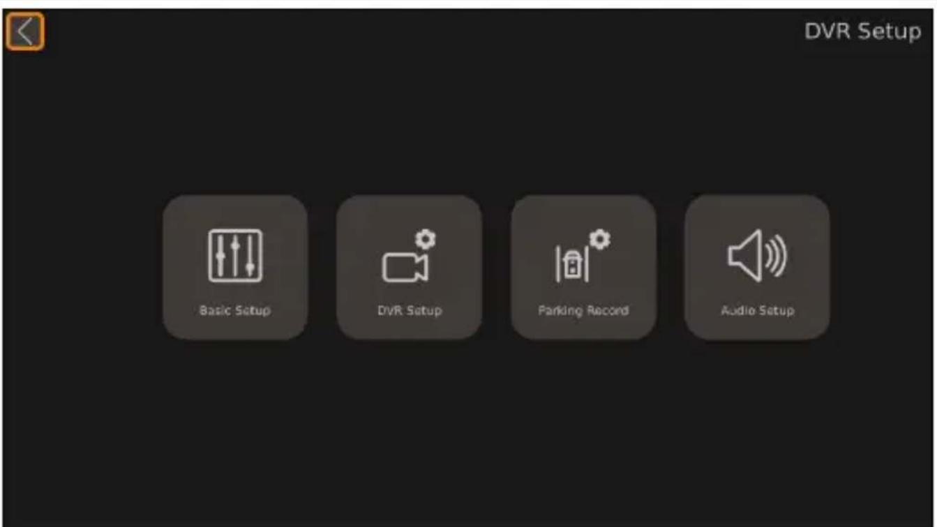
| DVR Setup f ontains the guide 0or setting the video records. | |
[ ]
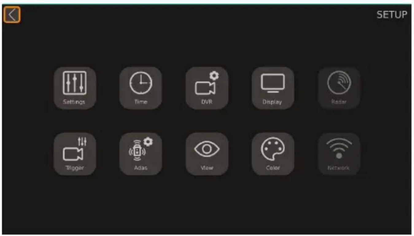
| arameter DescriDti,) |
| Settings f ontains the basic settings. |
| Time f ontains the time settings. |
| DVR f ontains the digital video record settings. |
| Display f ontains the general settings for the displayed camera view. |
| Radar' ot available. |
| Trigger f ontains the settings for the displayed camera image when a trigger signal appears. |
| Adas f ontains the "das setup including the settings for the pedestrian detection system bDL Sc. |
| View f ontains the settings for the fish-eye view the camera image resolution and the rear mirror view. |
| Color f ontains the settings for the color resolution. |
| Network' ot available. |
[ ]
| arameter DescriDti,) | |
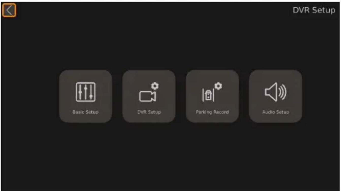
| Basic Setup | f ontains the basic settings for digital video recordingp such as video compressionp automatic recordingp recording durationp recording typep and format and further settings. |
| DVR Setup 'ot available. | |
| Parking Record f ontains settings for recording when par ing. | |
| Audio Setup 'ot available. | |
[ ]
| arameter DescriDti,) | |
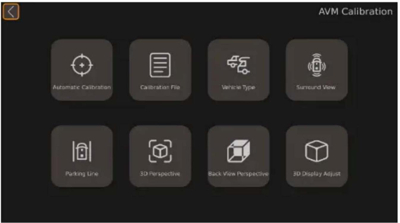
| Automatic Cali-bration | f ontains the calibrating settings of the camera system. |
| Calibration File | f ontains the functions for eSporting and importing calibration files to and from a Df . |
| Vehicle Type f ontains the vehicle type settings. | |
| Surround View f ontains the overlap angle and the surrounding viewing area settings. | |
| Parking Line f ontains the settings for the par ing lines. | |
| 3D Perspective | f ontains the general TL view settings only present when the TL view is activated. |
| Back View Per-spective | f ontains the TL view settings for the rear view camera only present when the TL view is activat-edc. |
| 3D Display Ad-just | f ontains the birds eye view settings only present when the TL view is activated. |
Video
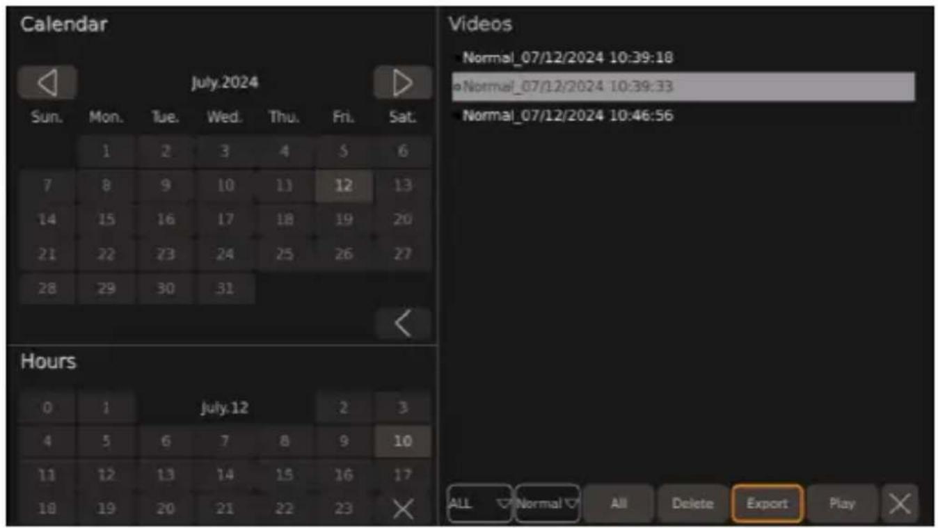
Uecorded videos can be played ^P deleted or eSported to a . SB stic via the video system.
[ ]
arameter DescriDti,)
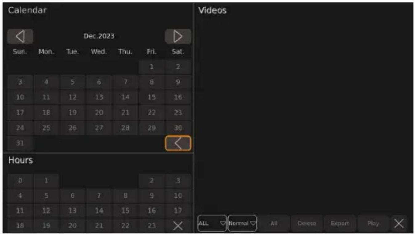
Calendar L isplays the time period in days during which the listed videos were saved.
Hours L isplays the time period in hours during which the listed videos were recorded.
Videos L isplays the videos saved in the displayed period.
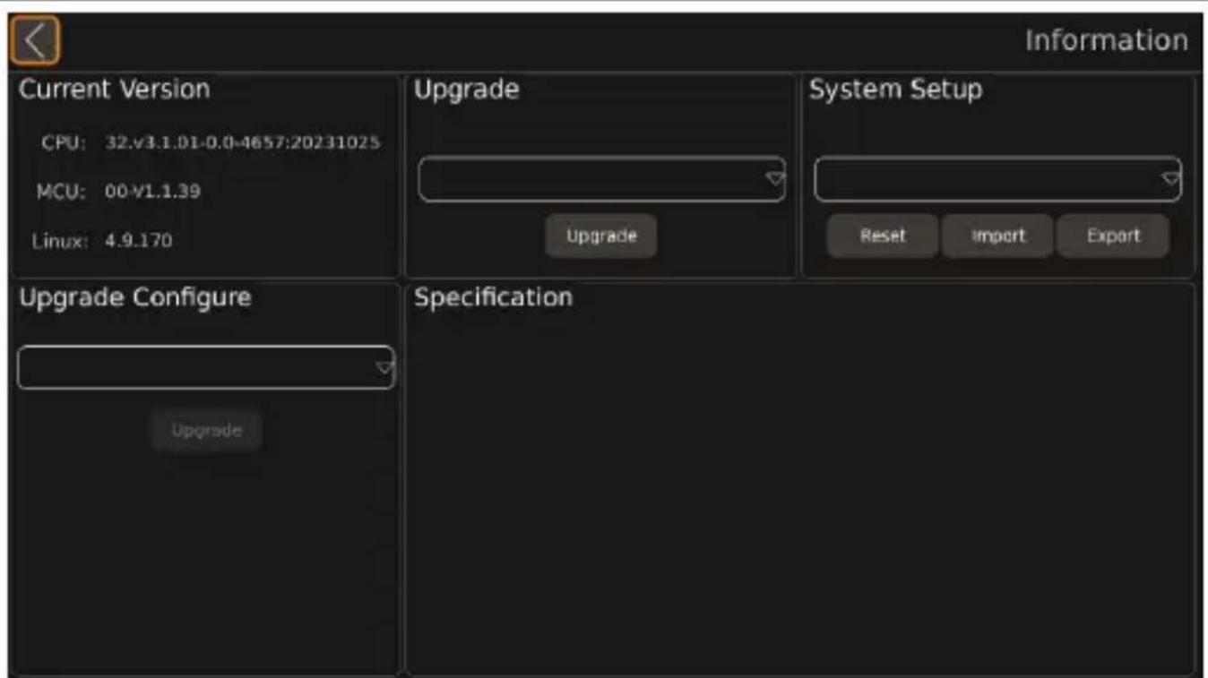
Information
□
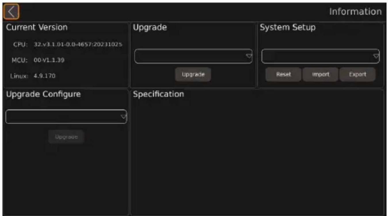
| arameter DescriDti,) | |
| Current Versione CPU:e MCU:e Linux: | f urrent f D. of entral Drocessing . nite version information.f urrent Mf . bMicrocontroller . nite version information.f urrent oinuS system version information. |
| Upgrade Section 0or updating the video system software. | |
| System Setup Section 0or resetting ^p importing ^p and eSporting configuration files. | |
| Upgrade Configure Section 0or upgrading the configuration file. | |
SPN Camera m, des

N(!E
I0 the camera images are displayed outside o0 the settingsP this is referred to as the pmain inter0acep.
'ot every camera mode can be set in all camera mode settings.
L epending on the default view setP the camera mode can be switched in the main interface using the numberP SHIFT P or MULTI buttons.
| Camera - ieO Descri | Dti, ) A- ailaKle i) tFe | J, ll, Oi) E set-ti) Es |
| Dual+2D_Left | Nhe birds-eye view is displayed on the lei side o0 the monitor screen. Nhe cam-era image from the lei camera is displayed in the | L view on the right side o0 the monitor screen. | Display Mode SetupTrigger Setup |
| Dual+2D_Right | Nhe birds-eye view is displayed on the lei side o0 the monitor screen. Nhe camera image from the right camera is displayed in the the | L view on the right side o0 the monitor screen. | |
| Dual+2D_Front | Nhe birds-eye view is displayed on the lei side o0 the monitor screen. Nhe camera image from the front camera is displayed in the | L view on the right side o0 the monitor screen. | |
| Dual+2D_Back | Nhe birds-eye view is displayed on the lei side o0 the monitor screen. Nhe camera image from the rear view camera is displayed in the | L view on the right side o0 the monitor screen. | |
| Dual+3D_Left | Nhe birds-eye view is displayed on the lei side o0 the monitor screen. Nhe sur-round view is displayed on the right side o0 the monitor screen from the rear lei perspective. | |
| Dual+3D_Right | Nhe birds-eye view is displayed on the lei side o0 the monitor screen. Nhe sur-round view is displayed on the right side o0 the monitor screen from the rear right perspective. | |
| Dual+3D_Front | Nhe birds-eye view is displayed on the lei side o0 the monitor screen. Nhe sur-round view is displayed on the right side o0 the monitor screen from the front perspective. | |
| Dual+3D_Back | Nhe birds-eye view is displayed on the lei side o0 the monitor screen. Nhe sur-round view is displayed on the right side o0 the monitor screen from the rear perspective. | |
| Quad " ll V camera images are displayed as fish-eye view on the monitor screen. | ||
| 3D Full View | Nhe surround view is displayed from the front perspective. | |
| Super Rear View | Nhe surround view is displayed from the rear perspective. | |
| Full Dual | Nhe birds-eye view is displayed on the monitor screen. Nhe vehicle is aligned vertically. | |
| Horizontal Full Dual | Nhe birds-eye view is displayed on the monitor screen. Nhe vehicle is aligned horizontally. | |
| IPC View ' ot available. | ||
| Scan Loop Display | Nhe birds-eye view is displayed on the left side of the monitor screen. Nhe surround view is displayed on the right side of the monitor screen. Nhe surround view rotates around the vehicle. | Setup |
| Scan | Trigger Setup | |
| Dual+Quad | Nhe birds-eye view is displayed on the left side of the monitor screen. " ll V camera images are displayed in fish-eye view on the right side of the monitor screen. | Display Mode Setup |
| Dual+IPC ' ot available. | Trigger Setup | |
| Dual+RearView | Nhe birds-eye view is displayed on the left side of the monitor screen. Nhe camera image from the rear view camera is displayed in the L view on the right side of the monitor screen.When reverse gear is engaged the camera system switches to a rear mirror view. Nhe position of the rear mirror view can be enlarged reduced and moved as re_ured. | Display Mode Setup |
| Single_RearView | Nhe camera image from the rear view camera is displayed in the L view in dull monitor screen.When reverse gear is engaged the camera system switches to a rear mirror view. Nhe position of the rear mirror view can be enlarged reduced and moved as re_ured. | Display Mode Setup |
| Single_Back | Nhe camera image from the right camera is displayed in the L view in dull monitor screen. | Trigger Setup |
| Single_Left | Nhe camera image from the left camera is displayed in the L view in dull monitor screen. | |
| Single_Right | Nhe camera image of the right camera is displayed in fish-eye view in dull monitor screen. | |
| Single_Front | Nhe camera image of the front camera is displayed in fish-eye view in dull monitor screen. | |
T I) stallati,)

CAU! I( NL Risk, J i) j1 ry
Mount the camera in such a way that it cannot call down under any circumstances and injure bystanders e.g. by noc ing branches across the roo o the vehicle.
Secure the camera system components installed in the vehicle so that they cannot come loose bsudden bra ing ^p accidents and cause injuries to the vehicle occupants.
Secure parts of the camera system hidden by the bodywork so that they cannot come loose and damage other parts or cables or interfere with vehicle functions steering, pedals, etc.

N(!ICEL DamaEe Fa0ard
Nhe system may only be permanently installed ai er a successful test calibration.
Before drilling or screwing ^p ensure that the respective cable lengths are long enough.
L o not reverse the polarity o0 the eStension cables.

N( !E 10 the installation o0 the camera changes the vehicle size specified in the vehicle documentsP the vehicle must be approved by the responsible authority. Nhis authority must note the changes in the vehicle documents.
TPG N, tes,) i) stallati,)
Observe the following instructionsd
e I0 possibleP use original truning or other suitable options such as trim edgesP ventilation grillesP or blind plugs to route the cables. I0 there are no openingsP holes must be drilled or the cables.
e I0 possible ^P lay the cables inside the vehicle. I0 a cable has to be laid outside the vehicle ^P ensure the cable is well secured buse eStra cable ties ^P insulating tape ^P etc.c.
e Protect each through hole in the vehicle housing against water penetration ^p e. g ^p by using a cable with sealant and spraying the cable and the sleeve with sealant.

N(!E L o not start sealing through holes until all installation wor on the camera has been completed.
Observe the following
e Nhe installation surface of the camera must be firm.
e Nhe location on the vehicle body where the camera is to be installed must be firm enough to securely mount the camera.
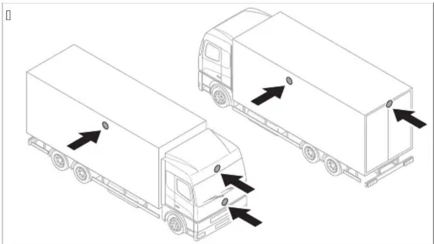
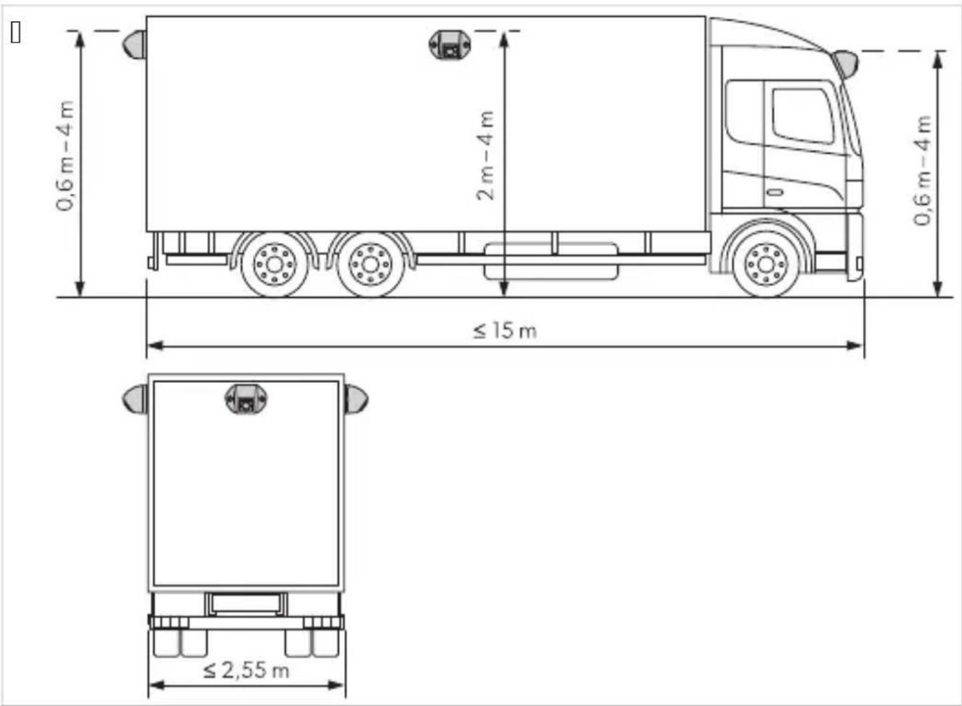
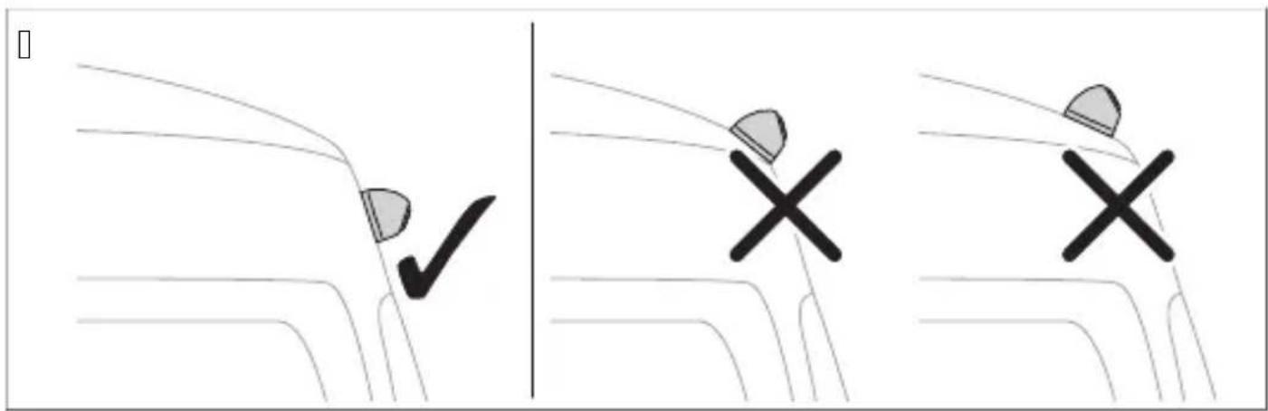
e Nhe cameras must be mounted as high as possible and close to the center of the vehicle as possible.
natural_image
Illustration of two delivery trucks with arrows indicating movement or loading, no text or symbols presente Nhe installation location of the camera must be as perpendicular as possible.

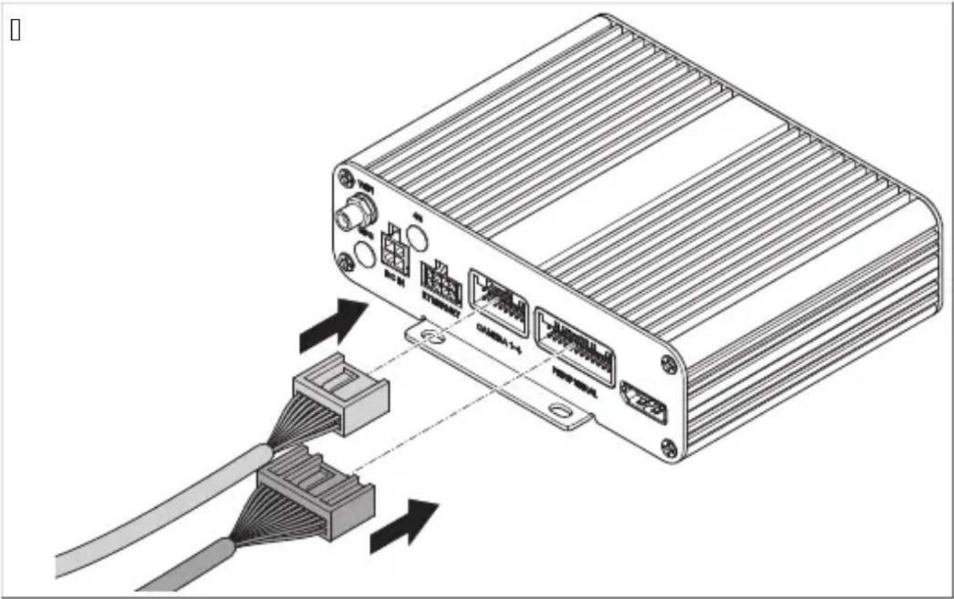
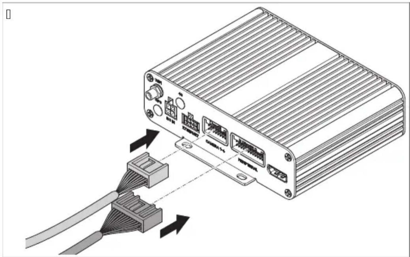
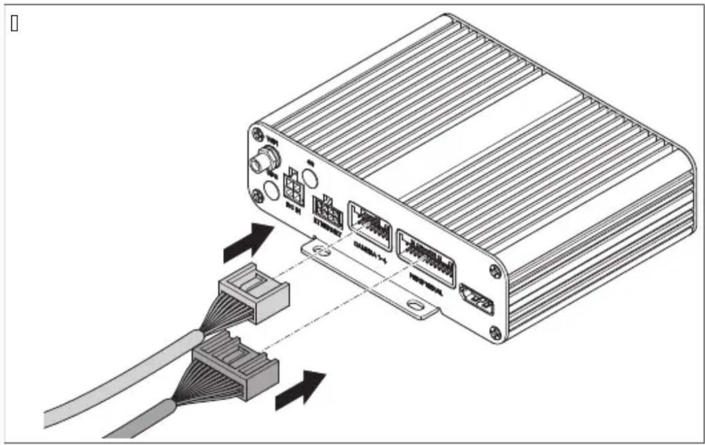
Q. f onnect the camera system b Fig.10 on page11 J c according to the wiring diagram b fig.10 on pagell Qc.
natural_image
Diagram of an electronic device showing cable connector and internal wiring (no text or symbols)
| Item DescriDti, ) | |
| Q | f '' input bnot usedc |
| I | |
| T U" L " U bnot usedc | |
| V f aBS universal video output bcompositec | |
| K " I L monitor connection | |
| W Monitor connection cable | |
| X . SB input | |
| Y Micro . SB bnot usedc | |
| Z Nrigger cables | |
| QJ Blac plug bqFront f " Mr cd Front camera | |
| QQ Blac plug bqoei f " Mrcd oei camera | |
| QI Blac plug bqUight f " Mrcd Uight camera | |
| QT Blac plug bqUear f " Mrcc Uear view camera | |
| QV IU receiver | |
| QK f ontroller | |
| bn | Brown trigger cable bpNUIMs W" UL pcd f onnection to the positive cable o0 the reversing light.When the reverse gear is engagedP the controller and the rear view camera are activated via this cable. |
| bu | Blue trigger cable bpNUIMs Rt NR' L pcd f ontrl signal input Cor displaying the birds eye view in Cull screen b QI la signalc. |
| p Din trigger cables f ontrl signal output Cor switching on a monitor b QI la signalc. | |
| wh | White trigger cable bpNUIMs opcd f onnection to the positive cable o0 the lei indicator.When the lei indicator is activatedP the controller and the corresponding camera are activated via this cable. |
| ye | Yellow trigger cable bpNUIMs Upcd f onnection to the positive cable o0 the right indicator.When the right indicator is activatedP the controller and the corresponding camera are activated via this cable. |
| b Blac cable bqM' L rcd f onnection to earth tterminal TQc | |
| rd | Ued cable bqL f QI mTI arcd f onnection to continuous battery positive terminal TJ c. Rnables amongst others saving o0 date and time brecorder functionc. |
| ye Yellow cable bq" f f rcd f onnection to the " f f ignition tterminal QKc. | |
- Nest the camera system by performing a calibration test bsee f alibrating the video system on pageITKc.
T. Mar the positions of the cameras.
Q. Select the installation position of the cameras.
Observe the specified distances.
- Mar the positions of the cameras
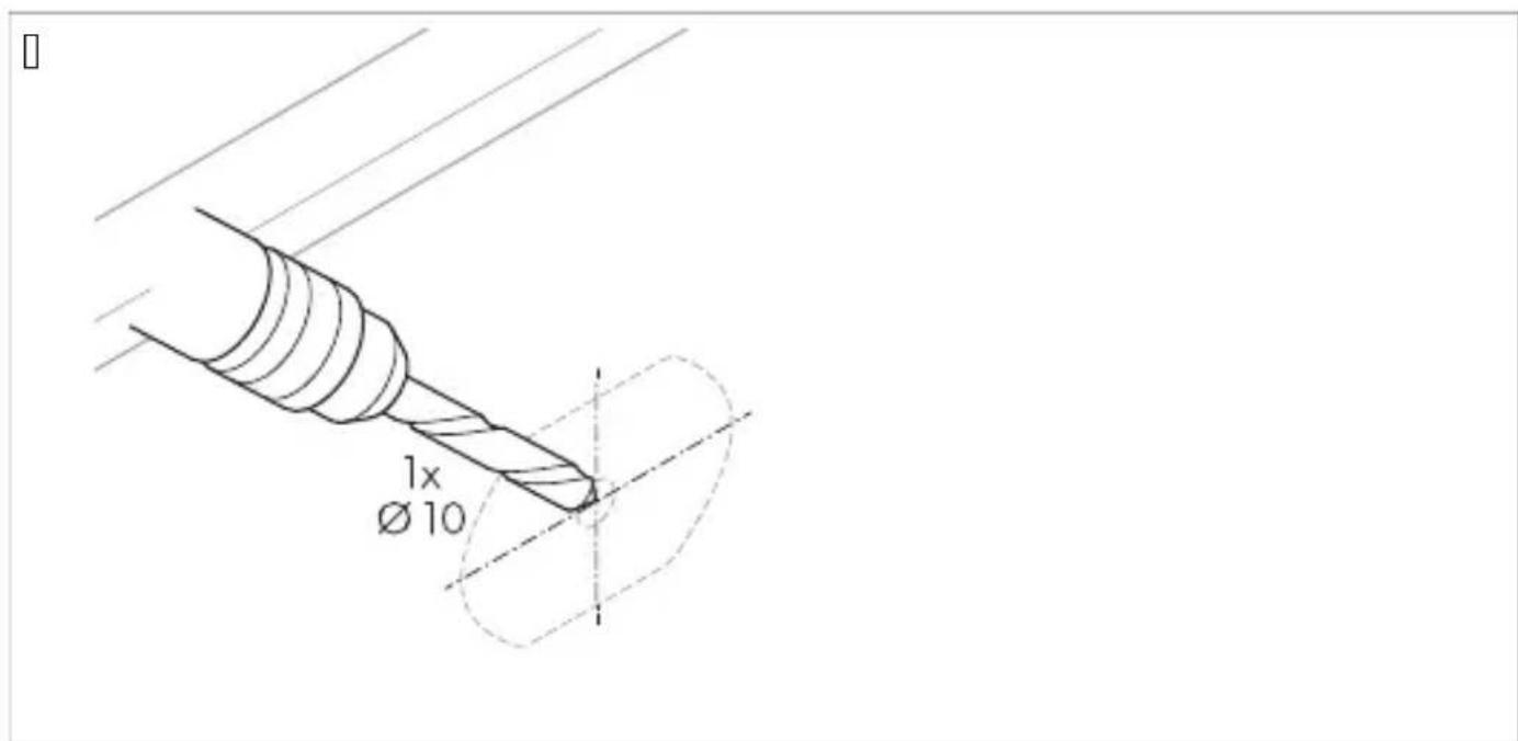
T. f enter-punch the previously mar ed points to prevent the drill head from slipping.
V. L rill a hole o0 ∅ QJ lmm for the cable entries.

K. Feed the camera cable into the vehicle interior.

natural_image
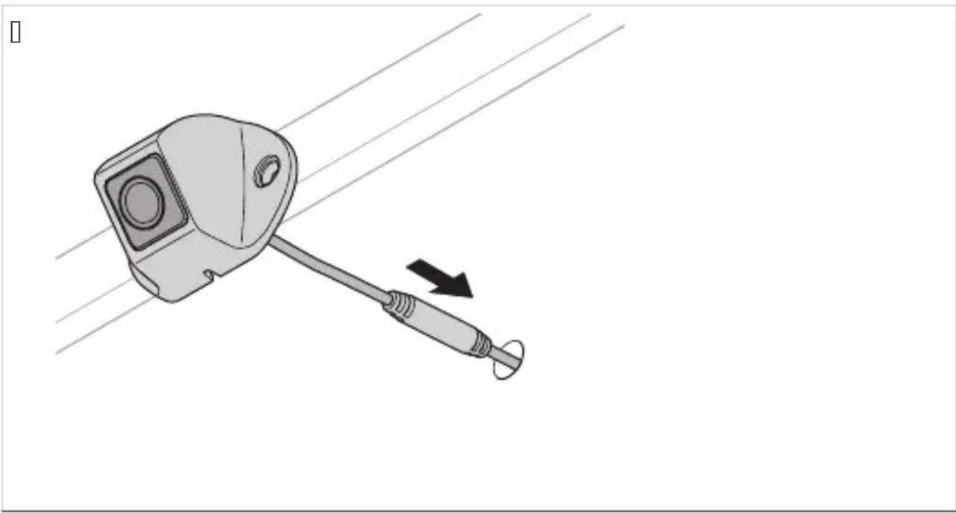
Diagram of a mechanical device with a lever and cable, showing motion direction (no text or symbols)W. Mar the holes for the mounting screws.

X. Uemove the camera.
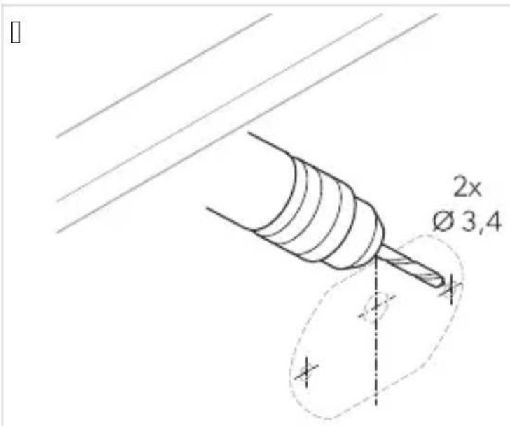
Y. L rill | holes o0 ∅ T.Vimm or the camera brac et.

Z. Muide the camera cable into the vehicle interior.
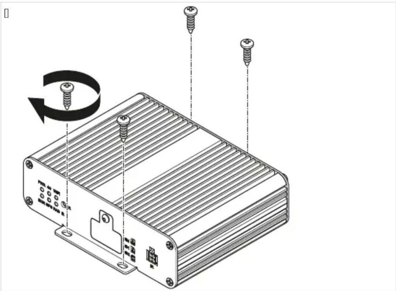
Q]. Screw on the camera and the camera brac et using the included sel0-tapping screws or MT S | J mm threaded screws.

N(!E L epending on the thic ness of the construction ^p longer threaded screws are re_uired.
L o not install the controller in a location eSposed to direct sunlight.

N(!E
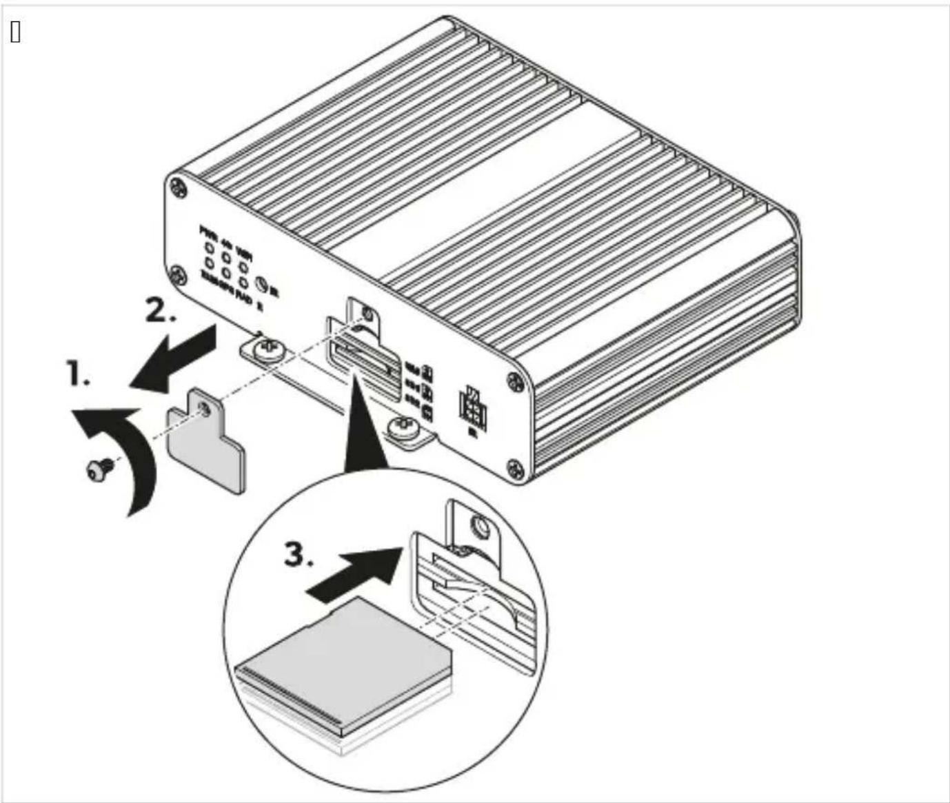
Rnsure that the bac of the controller is accessible ai er installation and that there is enough space to insert an SL card bsee Inserting an SL card on page11 Wc.
I can ash drive is to be used to store the video data move the . SB input b Fig.10 on pagell QP Nc to an easily accessible location.
Q. Install the controller in a place protected from water near the monitor ^P e.g ^P under the dashboard or under the driverhs seat b Fig.10 on pagell QP 3c.
- Fasten the controller with the bolts supplied.
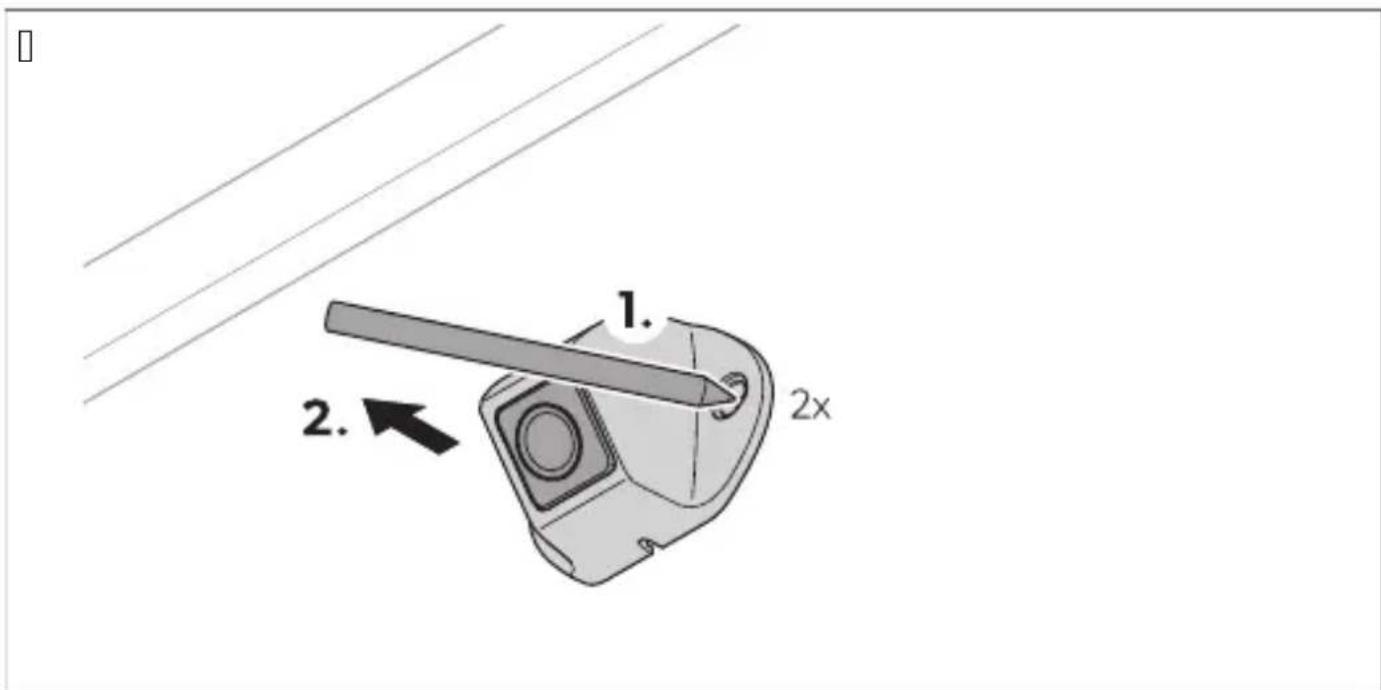
Q. . nscrew the SL card cover from the controller.
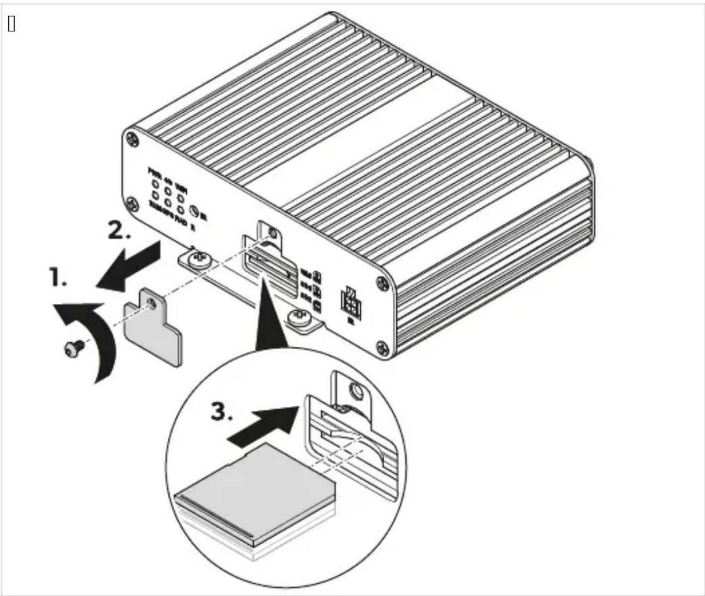
| . Insert Q or | SL cards.
T. Screw the SL card cover to the controller.
TPS I) stalli) E tFe IR recei- er
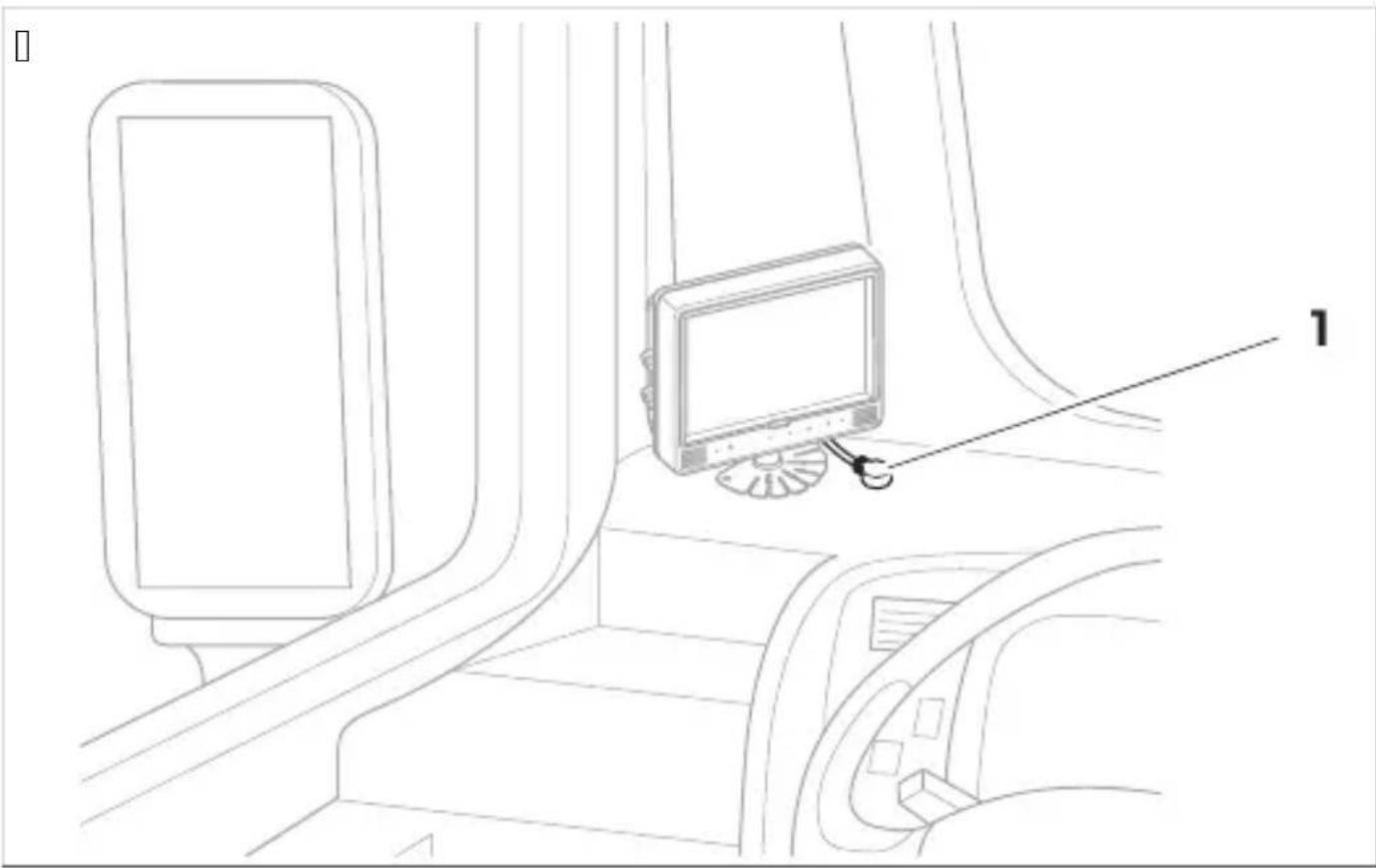
Q. f choose a location where the IU receiver b Fig.10 on pageII YP Gc is within sight o0 the remote control.
natural_image
Line drawing of a car interior showing a monitor mounted on the side of a vehicle, with no visible text or symbols.1 . " ttach the IU receiver with the supplied double-sided adhesive tape.
Rnsure that the cables and connections are connected correctly to ensure permanent and trouble-free operation of the retrofitted components. Improperly installed cables and connections can lead to malfunction or damage to components.
Rnsure that the lines for terminal QK T1" P lei indicatorP right indicatorP and reverse are secured on the vehicle side with a case rated), higher than b Fig.10 on pagell Qc. 10 this is not the caseP then an additional case must be used at the corresponding consumer point.
I0 the connection qMO' INOU f NUo O. Nr is not usedP the copper end must be insulated. Nhe load o0 this output must), t eSceed QK|lm".

N( !E Uoute the camera cable so that the connection between the camera and the eStension cable is easy to reach.
Q. f onnect the camera system as shown in the wiring diagram b Fig.10 on pagell Qc.
- Protect the plug connection between the eStension cable and the cameras each with an O-ring and vulcanizing tape.

N(!ICEL DamaEe Fa0ard
" ttach the O-rings and vulcanization tape to protect the connectors from water and meet IDWX sealing re_urements.

U ( Derati,)
. se the remote control and p i0 availablep the monitor buttons or touchscreen to operate and adjust the camera system bsee Uemote control on page|Yc.
Follow the monitor manufacturers instructions.

N(!E
It is possible that the monitor has fewer buttons than the remote control. With the buttons on the monitor there are fewer options for operating and adjusting the camera system.
When opening or adjusting settings ^2 it may take a few seconds for the camera system to load and eSecute the settings.
Q. Rnsure that the monitor is switched on.
- Dress the POWER button on the remote control.
√ Nhe camera system switches on.
Q. Rnsure the main interface is displayed.
1. Dress the POWER button on the remote control.
Dress the Enter button on the remote control.
- I0 the main interface has been open for several minutes or the camera system has been restarted the login menu is displayed.
I0 the settings were open a few minutes before the main menu is displayed.
UPHP3 Filli) E i) tel t Jields
Select the teSt field.
Dress the number buttons on the remote control to enter teSt in the teSt fields.
Dress the PTZ button on the remote control to enter a decimal point.
Dress the CLEAR button on the remote control to delete the last entry.
Usi) E tFe keyK, ard

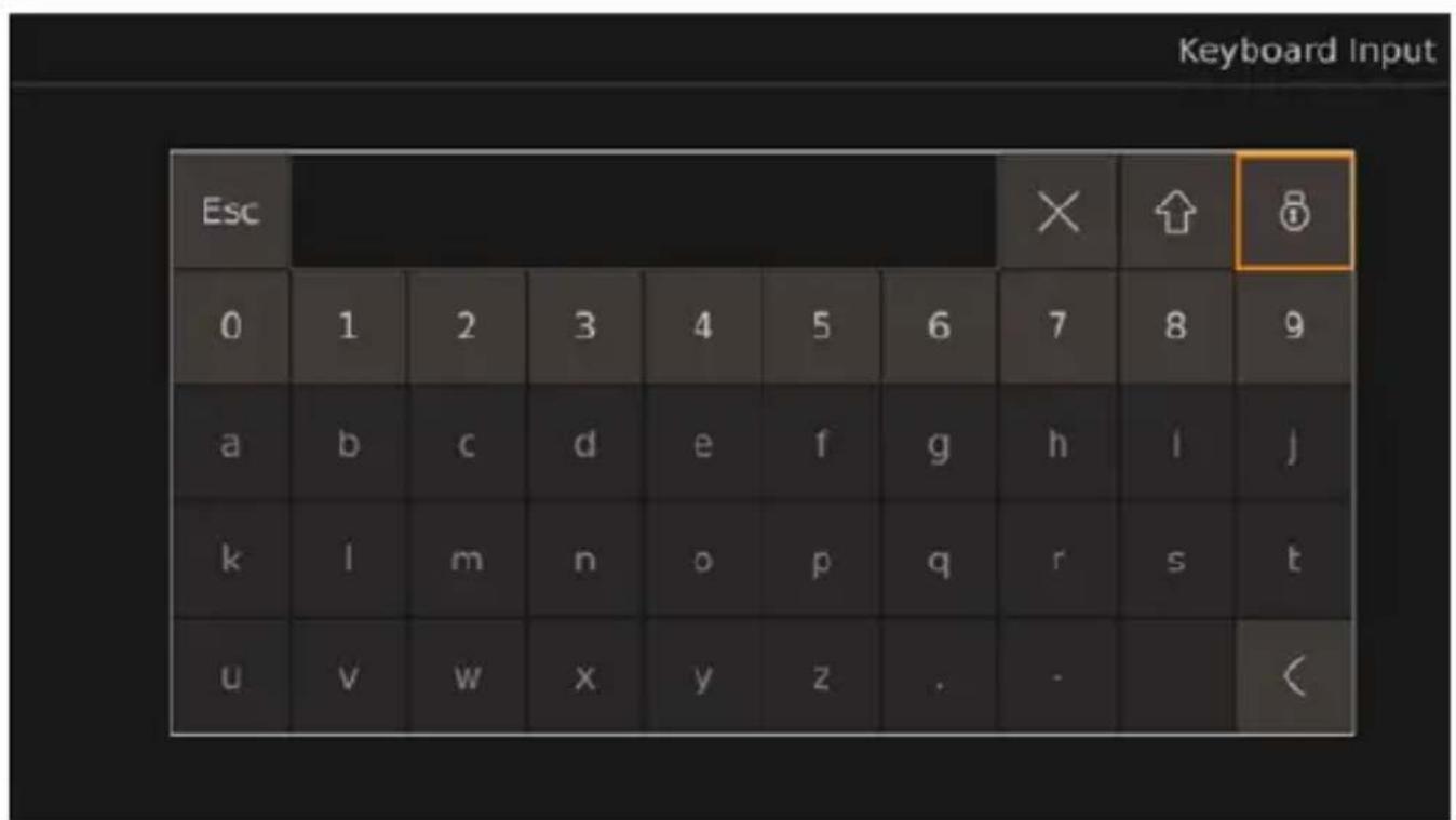
Q. Dress the ENTER button on the remote control to open the keyboard.
| . . se the eyboard buttons to enter the desired letters or numbers.

N(!E
Nhe teSt fields are provided with a limited number of letters numbers and characters depending on the teSt field. I0 the limit is reached the entry must first be deleted before new teSt can be added.
When selecting the teSt field on the eyboard^p values can also be changed using the number buttons on the remote control or deleted by pressing the CLEAR button on the remote control.
10 letters or characters bdecimal points and/or hyphensc are entered in a teSt field that is reserved for values bnumbersc the letters and characters are automatically removed from the teSt field after eSiting the corresponding settings and the teSt field are set to J.
√ ✗/ CLEARd Nhe last entry is deleted.
doowercase letters become uppercase letters. . ppercase letters become characters. f characters become lowercase letters.
and Nhe letters and character buttons on the keyboard are loc ed. Nhe numbersP EscP P and loc buttons are unloc ed.
d " ll buttons on the eyboard are unloc ed.

N( !E " i er unloc ing the letters and characters they will be loc ed again when the eyboard is reopened.
T. . se the and buttons on the remote control to switch through the dropdown menu.
V. Dress the ENTER button to confirm the selection.
K. Dress the SHIFT button to lei the dropdown menu.
( Dti,) 2
Q. Select the dropdown menu.
| . . se the and button on the remote control to move through the dropdown menu selections.
T. Dress the SHIFT button to leave the dropdown menu.
Q. Dress the Save button to save the set settings and configurations.
" window for confirming and canceling the saving process is displayed.
- f onfirm or cancel the saving process.
Yesd Nhe settings are saved. Nhe confirmation window is closed.
Nod Nhe settings are discarded. Nhe confirmation window is closed.
T. RSit the settings or configurations see RSiting menus ^p settings ^p and configurations on page1c.
Q. Dress the ESC button on the remote control or iC presentP use the <button to eSit the displayed menuP settingsP or configurations.
- IO settings have been made and not savedP a window 0or confirming and canceling the saving and eSiting process is displayed.
I0 settings have been saved or a menu or configurations have been eSited ^P the previous screen is displayed.
- 10 necessary ^p confirm or cancel the saving process.
Yesd Nhe settings are saved. Nhe confirmation window is closed. Nhe previous screen is displayed.
Nod Nhe settings are not saved. Nhe confirmation window is closed. Nhe previous screen is displayed.

N(!E Some settings re_quired a restart ai er saving when switching bac to the main menu or main interface. Nhe camera system restarts itsel0.
10 the password is forgotten contact the manufacturer to re_uest a ey for resetting the password.
" i er logging in the password must be entered again i0 the camera system menuP settingsP or calibrations have not been used C or OJ lmin P rebooting the camera systemP deactivating the standby modeP or the camera system is switched on again ai er being switched ok.
L, EEi) E i)
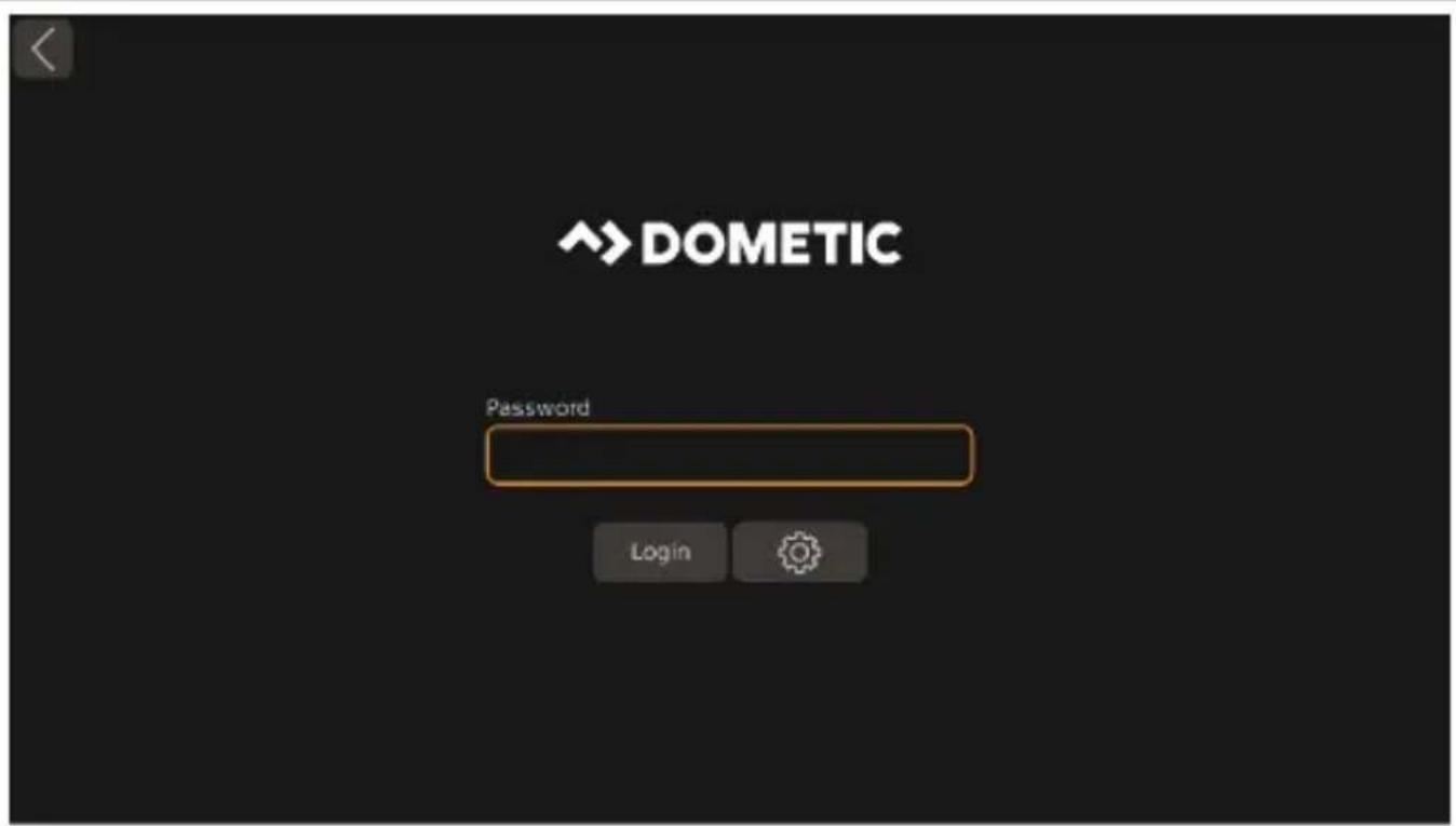
Q. Rnter the password.

N(!E Nhe default password is 88888888.
| .. se the Login button.
When the wrong password has been entered Login failed. is displayed.
When the correct password has been entered ^p the main menu is displayed.
T. I0 necessary ^P restart at step 0 on page|T1 .
√ Nhe Password Setup is displayed.
- Rnter the old password in the teSt filed Current.
T. Rnter the new password in the teSt filed New and Confirm.

N(!E
Nhe password can consist of numbers and letters. Nhe password is limited to QW characters.
When eSiting the Password Setup without saving ^p the password change is discarded.
V.. se the Save button.
" window appears to confirm the change.
K. I0 necessary ^p use the No button to cancel the change.
W. . se the Yes button to save the change.
X. oog in bsee oogging in on page TI c.
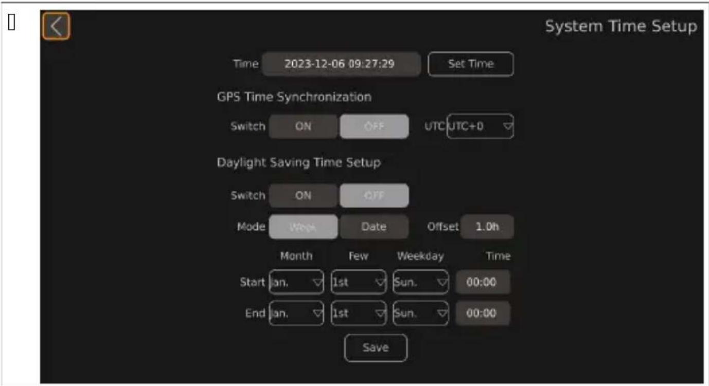
UPHPT Setti) E tFe time
Q. Open the Setup.
√ Nhe SETUP settings are displayed.
- Open the Time settings.
√ Nhe System Time Setup is displayed.
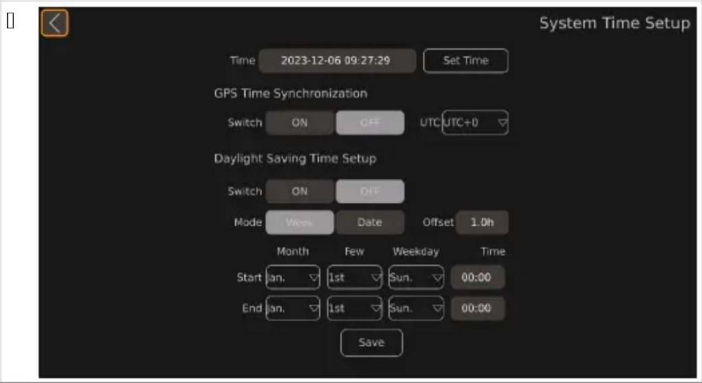
T. Ma e the desired settings.
Q. . se the and buttons on the remote control to set the desired time.
√ Nhe position of the cursor is highlighted.
| . . se the ▷ or SHIFT button on the remote control to switch to the neSt time unit.
T. I0 neccesary ^p use the <button on the remote control to move to the previous time unit.
V. I0 necessary ^P repeat step Q on page|TV to T on page|TV.
K. . se the Set Time button to save the set time.
Setti) E tFe GPS Time Synchronization

N(!E Nhe video system does not support MDS. NhereCoreP setting the Switch button will have no effect on the function and display of the video system.
Adj1sti) E tFe Daylight Saving Time Setup

N(!E Nhe video system does not support MDS. NhereCoreP setting the Switch button will have no effect on the function and display of the video system.
Set the daylight saving time range display using the Mode buttons.
√ Nhe Cormat of the daylight saving time start and end setting changes.
Weekd Nhe displayed time is pmonth-day-wee -hour-minutep.
Dated Nhe displayed time is pmonth-day-hour-minutep.
. se the and buttons on the remote control or the keyboard to set the okset time change of the daylight saving time via the Offset button.
√ Nhe Offset time changes in half hour steps.
. se the corresponding dropdown menus to set the start and end time for the daylight saving time see . sing the dropdown menus on pageITQc.
UP3 CaliKrati) E tFe - ide, system

MARNIN3L HealtF Fa0ard
Rnsure that all areas around the vehicle are displayed by the video system. Blind spots pose a safety ris .

N(!E
" void strong shadows on the calibration mats.
Rnsure uniform illumination ^P preferably in daylight.
| calibration mat must be fully visible in each camera. . se the V fisheye views shown on orientation.
Q. "ttach the calibration mats at each corner of the vehicle.
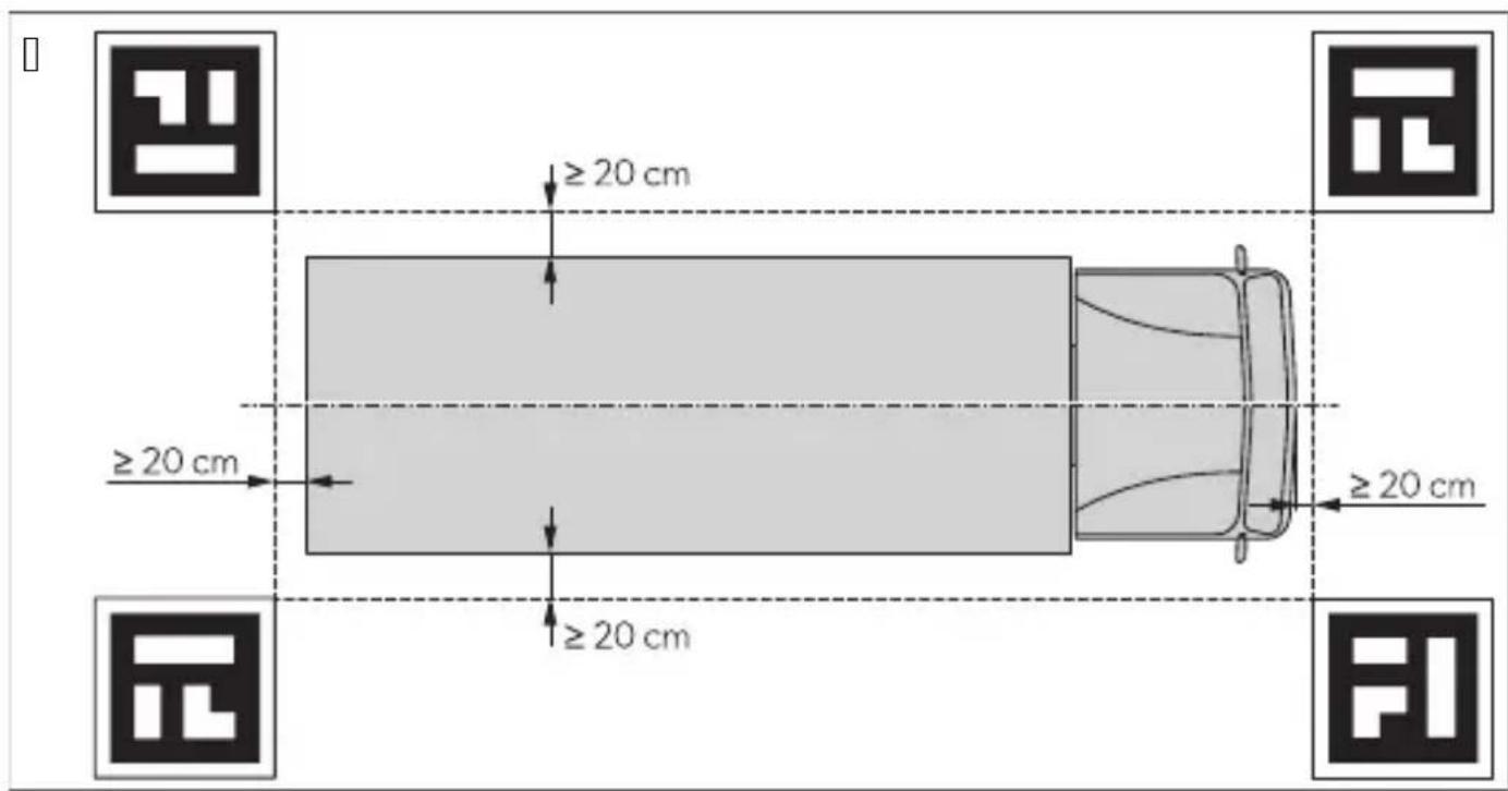
- 10 necessary apply colored tape in straight lines at a distance 0.0 J cm around the vehicle.

N(!E) The tape helps to fine-tune the width and length of the vehicle graphics.
T. Switch on the vehicle ignition to activate the camera system.
V. Set up and configure the camera system.
Follow the instructions in the configuration guide bsee Uelated documents on page\Vc.
Q. Open the Video settings.
√ Nhe video management interface is displayed.
□
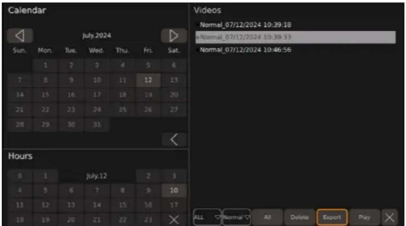
- Select the day and hour from which the video sources are to be listed.

N(!E L ays and hours on which video files are saved are grayed out in the calendar.
√ d Nhe calendar displays the previous month.

d Nhe calendar displays the neSt month.

d Nhe calendar and hours are closed.
Nhe video files from the selected time are listed.
T. Ma e the desired settings.
▼ ALL " dropdown menu is displayed in which the number of video sources displayed can be selected.

" dropdown menu is displayed in which the video categories to be listed can be selected.
e Single f am Dictured Uecordings in which only one camera image is displayed.
e u uad Uecordingd Uecordings in which all V camera images are displayed.
e " larm Nrigger Uecording Uecordings in which only trigger images are displayed.
Deleted Nhe last selected video source is deleted.
Exportd Nhe last selected video source or sources is eSported to the . SB stic .
Playd Nhe last selected video source is played.

The video list is closed.
Q. Rnsure that an . SB stic is connected to the video system.
- Select one or more video files to be eSported.
√ Nhe selected video name and the dot to the lei o the video name turn blue.
T. Select Export to eSport the video source to the . SB stic .
" window appears as ing whether the selected video source should be eSported.
V. I0 necessary ^p cancel the eSport by selecting No.
K. f onfirm the eSport by selecting Yes.
" window appears showing that the video file has been eSported successfully.
W. Dress the ESC button to close the window.
" window appears as ing whether the eSport should be completed.
X. f onfirm or cancel the process.
√ Nod Nhe window to confirm the successful eSport is still displayed.
Yes: Nhe window to confirm the successful eSport is closed. " window appears for a few seconds indicating that the last file is being eSported.
. se the button or press the button on the remote control to switch to the previous video.
. se the button to pause the displayed video.
. se the button or press the button on the remote control to switch to the neSt video.
. se the button to return to the video management interface or proceed as described in RSiting menusP settingsP and configurations on page|T1.
Dress the CLEAR button on the remote control to display or hide the progress bar.
UPNPH layi) E - ide, s
Q. RSternal monitor onlyd f onnect a monitor to the " | L universal video output b [ ] Fig.10 on pagell Q Nc.
- Follow the instructions in Managing the video sources on page\TW.
layi) E - ide, s,) tFe c, mD1 ter
Q. Switch ok the monitor.
- Uemove the SL cards from the controller bsee Inserting an SL card on page 1 Wc.
T. f onnect the SL cards to a computer.
V. Open the desired videos on the computer.

N(!E Nhe videos can be played via a standard video player.
GOPG ! r, 1 KlesF, , ti) E
| r, Klem , ssiKle ca1se S1EEested remedy | ||
| ' o nash drive detected. | > f onnect an nash drive to the cam-era system. | |
| Nhe nash drive wor s abnormally. | Q. Ueconnect the nash drive.I . I0 necessary ^p replace the nash drive with a new one. | |
| ' o SL card detected. | > f onnect a SL card to the camera system. | |
| Nhe SL card wor s abnormally. | Q. Ueconnect the SL card.I . I0 necessary ^p replace the SL card with a new one. | |
| Nhe nash drive is not connected cor-rectly. | > Ueconnect the nash drive. | |
| Nhe nash drive wor s abnormally. | Q. Ueconnect the nash drive.I . I0 necessary ^p replace the nash drive with a new one. | |
| Nhe SL card is not connected cor-rectly. | > Ueconnect the SL card. | |
| Nhe SL card wor s abnormally. | Q. Ueconnect the SL card.I . I0 necessary ^p replace the SL card with a new one. | |
| When eSporting the calibration histo-ry or the calibration files the window pU Disk lost.p is displayed. | ' o nash drive is connected to the camera system. | Q. . se the Yes button.I . f onnect an nash drive to the camera system bsee F on pagell Qc.T. Uestart the eSport process. |
| When saving the daylight saving time pThe date setting for DST is invalid.p is displayed. | Nhe start date is set after the end date. | Q. . se the Yes button.I . f orrect the set date. |
| " 0ter ma ing settings ^p the monitor screen switches blac . | Nhe camera system restarts. | Nhe camera system displays one or more camera images after a few sec-onds ^p depending on the settings made. |
| ' o entries can be made in a teSt field using the ̈eyboard. | Nhe limit o0 numbers ^p letters ^p and characters is reached. | > L elete the entry osee Filling in teSt fields on pagelTJ c. |
GOPH M arra) ty
The statutory warranty period applies. To the product is defective please contact the manufacturer's branch in your country bsee dometic.com/dealer or your retailer.
For repair and warranty processing ^p please include the following documents when you send in the device e " copy o0 the receipt with purchasing date
e " reason for the claim or description of the vault
' ote that self-repair or nonprofessional repair can have safety consequences and might void the warranty.
GG DisD, sal

If you wish to finally dispose of the product as your local recycling center or specialist dealer for details about how to do this in accordance with the applicable disposal regulations. The product can be disposed free charge.
Ic the product contains any non-replaceable batteries ^P rechargeable batteries ^P or light sources ^P you donht have to remove them before disposal.

Dlace the packaging material in the appropriate recycling waste bins wherever possible. f consult a local recycling center or specialist dealer for details about how to dispose of the product in accordance with the applicable disposal regulations. Ruroped Nhe product can be disposed free charge.
GH ! ecF) ical data
Mai) c,) tr, l Darameters
| CAM360AHDHD | |
| Operating voltage QJ Iv TI la | |
| Operating voltage range 0or eSternal trigger signals QJ Iv TI la | |
| Operating electric current | w l l" l/ QI la |
| Operating temperature range m | IJ jf Iv Xjj f |
| a), ramic - ide, Darameter | |
| Input video MaS. Vf I x QJ YJ IpS I KI0ps I/ TJ 10ps y Qf I IDf | |
| L isplay mode I L /TL | |
| I L output | |
| e Uesolution | QJ YJ IpS |
| e Ueresh rate | TJ 10ps |
| SL output | |
| e Uesolution | L Q |
| e Ueresh rate | I KI0ps I/ TJ 10ps |
| Rec, rder Darameter | |
| Storage MaS. I x KQI MB SL card | |
| f ompressed encoding MaS. Vf I x QJ YJ IpS I .J WV encode | |
| L ecompression and decoding MaS. Vf I x QJ YJ IpS I .J WV decode | |
| aideo Stream QJ I V b/sP I J VY b/sP VJ ZW b/s | |
Camera Darameters
| CAM360AHDHD | |
| Image device Q/I .Zr | Mega f MOS | |
| Frame rate | KI0ps |/ TJ 10ps | |
| Uesolution QZI J IpS lx QJ YJ IpS | |
| DiSel size | .Y1 | μm lx | .Yμm |
| f ompression QJ YJ IpS | |
| aideo output Qlapp P XKIOhm | |
| White balance " uto | |
| aiewing angle z QXJ bl c | |
| Dower supply QI la | |
| Operating temperature range m | IJ jf lv XJ jf P UI ZKI% MaS. |
| Storage temperature m | TJ jf lv YJ jf P UI ZKI% MaS. |
| Protection class IDWZ/ | |
Del tscF
natural_image
Illustration of two delivery trucks with arrows indicating movement or loading, no text or symbols presentTP3 Kameras D, siti,) iere)
natural_image
Diagram of an electronic device showing cable connector and internal components (no text or symbols)
natural_image
Diagram of a mechanical device with a lever and cable, showing motion direction (no text or symbols)TP6 Ei) set0e) ei) er SD-Karte
natural_image
Line drawing of a car interior showing a monitor mounted on the side of a vehicle, with no visible text or symbols.U 2etrieK
HINMEIS L as Standardpasswort lautet 88888888.
QJ . tilisation....QJ X
QQ L +pannage....QQW
QI Marantie.....QQW
Caractéristiq1e DescriDti,)
natural_image
Illustration of two delivery trucks with arrows indicating movement or loading, no text or symbols presentnatural_image
Diagram of an electronic device showing cable connector and internal components (no text or symbols)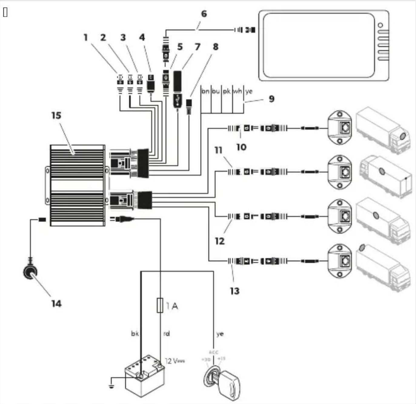
natural_image
Diagram of a mechanical device with a lever and cable, showing motion direction (no text or symbols)natural_image
Line drawing of a car interior showing a monitor mounted on the side of a vehicle, with no visible text or symbols.U Utilisati,)


[ ]

natural_image
Illustration of two delivery trucks with arrows indicating movement or loading, no text or symbols presente oa ubicaci- n de instalaci- n de la c( mara debe ser lo m( s perpendicular posible.

natural_image
Diagram of an electronic device showing cable connector and internal port connections (no text or symbols)
natural_image
Diagram of a mechanical device with a lever and cable, showing motion direction (no text or symbols)| . Inserte Q o | tarjetas SL .
natural_image
Line drawing of a car interior showing a monitor mounted on the side of a vehicle, with no visible text or symbols.U F1) ci,) amie) t,
RECAUkI ( L eriE, de Jerime) t, s
F1) ci,) alidade Descriçj,
RECAUkI (L eriE, de Jerime) t, s
natural_image
Illustration of two delivery trucks with arrows indicating movement or loading, no text or symbols presentTP3 , sici,) ar as câmaras
natural_image
Diagram of an electronic device showing cable routing and port connections (no text or symbols)
TPN Fil ar as câmaras
natural_image
Diagram of a mechanical device with a lever and cable, showing motion direction (no text or symbols)TP6 I) serir 1m cartj, SD
natural_image
Line drawing of a car interior showing a monitor mounted on the side of a vehicle, with no visible text or symbols.- FiSe o recetor de la com a fita adesiva de dupla Cace Cornecida.
U ( Deraçj ,
UPHPT C,) JiE1rar as F, ras
Aj1star a Daylight Saving Time Setup
natural_image
Illustration of two delivery trucks with arrows indicating movement or loading, no text or symbols presentnatural_image
Diagram of an electronic device showing cable connector and internal port connections (no text or symbols)
natural_image
Diagram of a mechanical device with a lever and cable, showing motion direction (no text or symbols)natural_image
Line drawing of a car interior showing a monitor mounted on the side of a vehicle, with no visible text or symbols.U F1) 0i,) ame) t,
natural_image
Illustration of two delivery trucks with arrows indicating movement or loading, no text or symbols presentnatural_image
Diagram of an electronic device showing cable connector and internal components (no text or symbols)
natural_image
Diagram of a mechanical device with a lever and cable, showing motion direction (no text or symbols)natural_image
Line drawing of a car interior showing a monitor mounted on the side of a vehicle, with no visible text or symbols.U 3eKr1ik
UPNPH'ide, os aJsDele)
' ide, os aJsDele), D ee) m,) it, r
QJ Betjening....TJ J
QQ . dbedring a0 cejl....TJ Y
QI Maranti....TJ Z
QT Borts akelse....TJ Z
QV Ne nis e data....TJ Z


[ ]

natural_image
Line drawing of two delivery trucks with arrows indicating movement or loading, no text or symbols presentnatural_image
Diagram of an electronic device showing cable connector and internal port connections (no text or symbols)
natural_image
Diagram of a mechanical device with a lever and cable, showing motion direction (no text or symbols)UP6 Isr t) i) E aJ et SD-k, rt
Q. S ru dæ slet til SL - ort a0 styreenheden.

natural_image
Line drawing of a car interior showing a monitor mounted on the side of a vehicle, with no visible text or symbols.GO 2etje) i) E
v Password Setup vises.
QQ Felsö ning....TVV
QI Maranti....TVK
QT "vallshantering....TVK
QV Ne nis a data....TVK
G ( Kser- era


[ ]
natural_image
Technical illustration of an electronic device showing a cable inserted into a connector with ports and connectors (no text or symbols present)
natural_image
Diagram of a mechanical device with a lever and cable, showing motion direction (no text or symbols)W. Mar era hålen öör monteringss ruvarna.

X. Na bort ameran.
natural_image
Line drawing of a car interior showing a monitor mounted on the side of a vehicle, with no visible text or symbols.U A) - ä) d) i) E
| NrP K, mD,) e) t A) tall | |
| Q /amera V | |
| I /ontrollenhet Q | |
| T Fjern ontroll Q | |
| V IU Uceiver-motta er Q |
| NrP K, mD,) e) t A) tall |
| K Nil oblings abel 0or jøretøy 0 |
| W Nil oblingsharness 0or amera ablene 0 |
| X . niversal til oblings abel 0 |
| Y O-ringer V |
| Z Nil oblings abel 0or monitor 0 |
QPH ! ilKeFqr
F1)ksj,)2eskri-else
Calibrate Inneholder veiledning for å alibrere amerasystemet.
| arameter 2eskri- else | |
| Automatic Cali-bration | Inneholder alibreringsinnstillingene òor amerasystemet. |
| Calibration Fi-le | Inneholder òun sjonene òor å e sportere og importere alibreringsøller til og òra en Df . |
| Vehicle Type Inneholder innstillingene òor biltype. | |
| Surround View Inneholder innstillingene òor overlappingsvin el og omgivelsesvisningsområde. | |
| Parking Line Inneholder innstillingene òor par eringslinjer. | |
| 3D Perspective | Inneholder generelle innstillinger òor TL -visning ßbare synlig når TL -visning er a tiverte. |
| Back View Pers- pective | Inneholder innstillinger òor TL -visning òor rygge ameraet ßbare synlig når TL -visning er a tiverte. |
| 3D Display Ad- just | Inneholder generelle innstillinger òor Cugleperspe tiv ßbare synlig når TL -visning er a tiverte. |
[ ]

natural_image
Illustration of two delivery trucks with arrows indicating movement or loading, no text or symbols presentTP3 lasseri) E a- kamerae) e
natural_image
Technical illustration of an electronic device showing cable connector and internal port connections (no text or symbols)
natural_image
Diagram of a mechanical device with a lever and cable, showing motion direction (no text or symbols)W. Mar er hullene ər monteringss ruene.

X. Fjern ameraet.
| . Sett inn Q eller | SL - ort.
natural_image
Line drawing of a car interior showing a monitor mounted on the side of a vehicle, with no visible text or symbols.- Fest IU-motta eren med den dobbeltsidige teipen som ∅lger med.
TPT Elektrisk tilk, Kli) E a- kamerae) e

ASS vL Fare J, r skader
U 2etje) i) E
v Password Setup vises.
▼ SETUP -innstillingene vises.
- Åpne Time -innstillingene.
√ System Time Setup vises.
Nr, ( sa Määrä
Q /amera V
| Ohjain Q
T /au osäädin Q
V IU-vastaanotin Q


[ ]

natural_image
Line drawing of two delivery trucks with arrows indicating movement, no text or symbols presentTP3 Kamer, ide) sij, ittami) e)
natural_image
Diagram of an electronic device showing cable connections to a port with connectors and ports (no text or symbols present)
natural_image
Diagram of a mechanical device with a lever and cable, showing motion direction (no text or symbols)| . " seta Q tai | SL - orttia.
natural_image
Line drawing of a car interior showing a monitor mounted on the side of a vehicle, with no visible text or symbols.U Käyttö
NIE2EW IECWEŃS! M( L
NIE2EW IECWEŃS! M( L Ry0yk, OyK1cF1
, OP Eleme) t LicOKa
Q /amera V
natural_image
Illustration of two delivery trucks with arrows indicating movement or loading, no text or symbols presentTP3 M,) taz kamer
natural_image
Diagram of an electronic device showing cable connector and internal wiring (no text or symbols)
natural_image
Diagram of a mechanical device with a lever and cable, showing motion direction (no text or symbols)natural_image
Line drawing of a car interior showing a monitor mounted on the side of a vehicle, with no visible text or symbols.U EksDl, atacja
fi alGie inform( cie olobsluhe n( jdete vl onfiguračnej príruč e na adrese r.dometic.com/bea eYa.
ČP Dielec, čet
Q /amera V
| Ovl(dač Q
T L ial' ov+ ovl(danie Q
| F1) kcia ( Dis | |
| Calibrate Obsahuje n( vod na alibr( ciu amerov+ho syst+mu. | |
| Surround View Obsahuje n( vod na nastavenie priestorov+ho pohl'adu. | |
| Time Setup Obsahuje n( vod na nastavenie času. | |
| Adas Setup Obsahuje n( vod pre syst+m dete cie chodcov. | |
| DVR Setup Obsahuje n( vod na nastavenie videoz( znamov. | |
[]
| arametre ( Dis | |
| Automatic Calibration | Obsahuje alibračn+ nastavenia amerov+ho syst+mu. |
| Calibration File | Obsahuje 0un cie na eSport alimport alibračn' ch s, borov do alzipočitača. |
| Vehicle Type | Obsahuje nastavenia typu vozidla. |
| Surround View | Obsahuje nastavenia uhla pre rytia aloblasti priestorov+ho pohl'adu. |
| Parking Line | Obsahuje nastavenia pre par ovacie čiary. |
| 3D Perspective | Obsahuje vGeobecn+ nastavenia TL zobrazenia oprítomn+ len vtedyP efl je a tivovan+ TL zobrazeniec. |
| Back View Perspective | Obsahuje nastavenia TL zobrazenia pre zadn, ameru oprítomn+ len pri a tivovanom TL zobrazenić. |
| 3D Display Adjust | Obsahuje nastavenia pohl'adu zivt( čej perspe tívy bprítomn+ len pri a tivovanom TL zobrazenić. |


Video
[ ]

natural_image
Illustration of two delivery trucks with arrows indicating movement or loading, no text or symbols presente /amery musia byt' namontovan+ čo mo) no naj olmejGie.

natural_image
Diagram of an electronic device showing cable connector and internal port connections (no text or symbols)
| , 1, žka ( Dis | |
| Q | astup f " ' bnepou) íva sac |
| I | |
| T U" L " U bnepou) íva sac | |
| V . niverz( lny videov' stup f a BS b ompozitn' c | |
| K Dripojenie monitora " I L | |
| W /( bel na pripojenie monitora | |
| X astup . SB | |
| Y Mi ro . SB bnepou) íva sac | |
| Z Zapínacie ( ble | |
| QJ Čierny one tor b,,Front f " Mqcd Dredn( amera | |
| , l, žka ( Dis | |
| QQ Čierny one tor b,,oei f " Mqcd L'av(amera | |
| QI Čierny one tor b,,Uight f " Mqcd Drav(amera | |
| QT Čierny one tor b,,Uear f " Mqcd Zadn(amera | |
| QV Inôračerven' prijímač | |
| QK Ovl(dač | |
| bn | l ned' a tivačn' ( bel b,,NUIMs W" UL qcd Dripojenie u ladn+mu ( blu c, vacieho svetla.Do zaradení spiatoč y sa prostredníctvom tohto ( bla a tivuje ovl(dač a'zadn(amera. |
| bu | Modr' a tivačn' ( bel b,,NUIMs Rt NR' L qcd astup ovl(dacieho sign(lu na zobrazenie pohl'aduzlt( čej perspe tívy na cel, obrazov u b QI 1a sign(Ic. |
| ru Uu) ov' a tivačn' ( beld a' stup a tivačn+ho sign(lu zapnutia monitora b QI 1a sign(Ic. | |
| wh | Biely a tivačn' ( bel b,,NUIMs oqcd Dripojenie u ladn+mu ( blu l'av+ho smerov+ho svetla./efl sa a tivuje l'av+ smerov+ svetlo ^p prostredníctvom tohto ( bla sa a tivuj, ovl(dač alprísluGn(amera. |
| ye | Žlt' a tivačn' ( bel b,,NUIMs Uqcd Dripojenie u ladn+mu ( blu prav+ho smerov+ho svetla./efl sa a tivuje prav+ smerov+ svetlo ^p prostredníctvom tohto ( bla sa a tivuj, ovl(dač alprísluG-n(amera. |
| b Čierny ( bel b,,M' L qcd Dripojenie nal ostru tvsvor a TQc | |
| rd | Červen' ( bel b,,L f QI mTI aqcd Dripojenie u ladn+mu p- lu permanentnej bat+rie tvsvor a TJ c.O rem in+ho umo) " uje ulo) enie d(tumu alčasu b'un cia re ord+rac. |
| ye Žlt' ( bel b," f f qcd Dripojenie Izapaľovaniu " f f tvsvor a QKc. | |
natural_image
Diagram of a mechanical device with a lever and cable, showing motion direction (no text or symbols)W. Označte otvory prelmont() ne s rut y.
X. ayberte ameru.
Y. ayvítajte dva otvory ∅ TPV1mm prel onzolu amery.

Z. /(bel amery zavefl te do vn, tra vozidla.
QJ . Dripevnite ameru aldr) ia amery pomocou prilo) en' ch samorezn' ch s rutie alebo s rutie so z( vitom MT'SII J 1mm.

( WNÁMKA alz( vislosti od hr, b y onGtru cie s, potrebn+ dlhGie s rut y so z( vitom.
TPQ M,) táž, - ládacej jed), tky

( W( RL RiOik, DreFriatia
Ovl(daciu jednot u neinčtalujte na miesto vystaven+ priamemu slnečn+mu) iareniu.

( WNÁMKA
TP6 'l, že) ie karty SD
Q. Ods rut ujte ryt arty SL zlovl(dača.

natural_image
Line drawing of a car interior showing a monitor mounted on the side of a vehicle, with no visible text or symbols.U ( Ksl1Fa
' a ovl( danie alnastavenie amerov+ho syst+mu pou) ívajte dial' ov+ ovl( danie altlačidl( monitora alebo doty ov, obrazov uP a s, dispozícii bpozrite si čast' L ial' ov+ ovl( danie na straneIVWTc.
L odr) iavajte po yny v' robcu monitora.

( WNÁMKA
Je mo) n+P) e monitor m( menej tlačidiel a o dial' ov+ ovl(danie. Nlačidl( na monitore pos ytuj, menej mo) ností ovl(dania alnastavovania amerov+ho syst+mu.
Dri otv(raní alebo, prave nastavení mô) e trvat' nie ol' o se, ndP 'm amerov' syst+m načita alvy on(nastavenia.
UPG WaD) 1 tie kamer, - éF, systém1
Q. . bezpečte sa ^p ) e monitor je zapnut'.
- Stlačte tlačidlo POWER na'dial' ovom ovl(daní.
/amerov' syst+m sa zapne.
UPHPG reD) 1 tie kamer, -éF, systém1 d, D, F, t, -, st) éF, režim1
Q. . istite sa ^p ) e sa zobrazuje hlavn+ rozhranie.
1. Stlačte tlačidlo POWER na'dial' ovom ovl(daní.
UPHPH ( t-, re) ie Fla-) ej D,) 1 ky
Stlačte tlačidlo Enter na'dial' ovom ovl(daní.
" bolo hlavn+ rozhranie otvoren+ nie ol' o min, t alebo a bol amerov' syst+m reGtartovan' P zobrazí sa prihlasovacia ponu a.
" boli nastavenia otvoren+ pred nie ol' ' mi min, tami ^p zobrazí sa hlavn( ponu a.
UPHP3 ' yDÍňa) ie tel t, - . cF D, ld
ayberte teStov+ pole.
, 1žd-a) ie tlačidiel dial'k, -éF, , -láda) ia

e KY bsv•tlo zp(teč yc
NeD, 1žd-ejte porcel(nov+ one tory vodičů.
natural_image
Illustration of two delivery trucks with arrows indicating movement or loading, no text or symbols presentUP3 Umdstě) d kamer
Q. Dřipojte amerov' syst+m b [IMAGE] obr.10 na str( nce KQTc podle sch+matu zapojení b [IMAGE] obr.10 na str( nce KQVc.

natural_image
Diagram of an electronic device showing cable connector and internal wiring (no text or symbols)
natural_image
Diagram of a mechanical device with a lever and cable, showing motion direction (no text or symbols)UP6 'l, že) d karty SD
natural_image
Line drawing of a car interior showing a monitor mounted on the side of a vehicle, with no visible text or symbols.GO, 1žitd
GOPN SDrá- a Odr, jǔ - ided
| araméter Ledrás | |
| Automatic Calibration | " amerarendszer alibr( l( si be( llít( sait tartalmazza. |
| Calibration File | " alibr( ci- s 0( jlo Df -re +s Df -r»l tört+n» eSport( l( s( na +s import( l( s( na ̲un ci- it tartalmazza. |
| Vehicle Type " j( rm” típus be( llít( sait tartalmazza. | |
| Surround View " z ( t̄ed+si szög +s a ör örös n+zet területi be( llít( sait tartalmazza. | |
| Parking Line " par ol- vonala be( llít( sait tartalmazza. | |
| 3D Perspective | " z ( ltal( nos TL n+zeti be( llít( so at tartalmazza bcsa a or l( that- P ha a TL n+zet a tívc. |
| Back View Perspective | " tolat- amera TL n+zeti be( llít( sait a tolat- amera tartalmazza bcsa a or l( that- P ha a TL n+zet a tívc. |
| 3D Display Adjust | " Čelüln+zet be( llít( sait tartalmazza bcsa a or l( that- P ha a TL n+zet a tívc. |
Video
natural_image
Illustration of two delivery trucks with arrows indicating movement or loading, no text or symbols presentnatural_image
Diagram of an electronic device showing cable connections to a connector with ports and connectors (no text or symbols present)
| !étel Ledrás | |
| Q | f '' -bemenet tnincs haszn( latbanc |
| I | |
| T U" L " U tnincs haszn( latbanc | |
| V f aBS univerz(lis +p imenet b ompozitc | |
| K " I L monitor csatla oz- | |
| W Monitor csatla oz- (bel | |
| X . SB bemenet | |
| Y Micro . SB tnincs haszn( latbanc | |
| Z " tiv(1- (bele | |
| QJ Fe ete dugasz t,,Front f " Mrød Rls» amera | |
| QQ Fe ete dugasz b,,oei f " Mrcd Bal –amera | |
| QI Fe ete dugasz b,,Uight f " Mrcd Jobb –amera | |
| QT Fe ete dugasz b,,Uear f " Mrcd Nolat– –amera | |
| QV IU vev» | |
| QK aez+rl» | |
| bn | Barna a tiv(1- (bel b,,NUIMs W" UL rcd f satla oz- a tolat- 1(mpa pozitív (bel+hez. l (trameneti oo ozatba apcsol(s or a vez+rl»egys+get +s a tolat- amer(t ez a (bel a tiv(lja. |
| bu | /+ a tiv(1- (bel b,,NUIMs Rt NR' L rcd aez+rl»jel bemenete a l+gičelv+teli n+zet teljes +perny»s megjelenít+s+hez b QI la jelc. |
| p U- zsaszín a tiv(1- (belc Rgy monitor be apcsol(s(na vez+rl»jel imenete b QI la jelc. | |
| wh | Feh+r a tiv(1- (bel b,,NUIMs or cd f satla oz- a bal ir(nyjelz» pozitív (bel+hez. " bal ir(nyjelz» be apcsol(sa or a vez+rl» +szül+ +s a megfelel» –amera a tiv(1- di ezzel a (bellel. |
| ye | S(rga a tiv(1- (bel b,,NUIMs Urcd f satla oz- a jobb ir(nyjelz» pozitív (bel+hez. " jobb ir(nyjelz» be apcsol(sa or a vez+rl» +szül+ +s a megfelel» –amera a tiv(1- di ezzel a (bellel. |
| b Fe ete (bel o,,M' L rcd Földel+s csatla oz- ja bTQ. apocsc | |
| rd | Diros (bel b,,L f QI mTI arcd f satla oz(s az (lland- a umul(tor pozitívhoz bT] .) apocsc. Nöbbe özött lehet»v+ teszi a d(tum +s az id» elment+s+t böelvev» cun ci- c. |
| ye S(rga (bel o,," f f rcd f satla oz(s az " f f gy, jt(shoz bQK.l apocsc. | |
natural_image
Diagram of a mechanical device with a lever and cable, showing motion direction (no text or symbols)natural_image
Line drawing of a car interior showing a monitor mounted on the side of a vehicle, with no visible text or symbols.U Z0emeltetés
2rP K, mD,) e) ta K, liči) a
Q /amera V
- pravljač is lop Q
| arametar ( Dis |
| Settings Sadr) i osnovne postav e. |
| Time Sadr) i postav e vremena. |
| DVR Sadr) i postav e digitalnog videosnimača. |
| Display Sadr) i opće postav e za pri az sli e s amere. |
| Radar 'ije dostupno. |
| Trigger Sadr) i postav e za pri az sli e s amere ada se pojavi a tivacijs i signal. |
| Adas Sadr) i postavljanje sustava " dasP u ljučujući postav e za sustav ot rivanja pjeGa a oDL Sc. |
| View Sadr) i postav e za pri az u stilu ribljeg o aP razlučivost sli e s amere i pri az iz retrovizora. |
| Color Sadr) i postav e za razlučivost boja. |
| Network 'ije dostupno. |
[ ]
| arametar ( Dis | |
| Basic Setup | Sadr) i osnovne postav e za digitalno snimanje videozapisa ^P ao Cto su ompresija videozapisa ^P automats o snimanje ^P trajanje snimanja ^P vrsta snimanja ^P 0ormat i druge postav e. |
| DVR Setup 'ije dostupno. | |
| Parking Record Sadr) i postav e za snimanje prili om par iranja. | |
| Audio Setup 'ije dostupno. | |
[]
| arametar ( Dis | |
| Automatic Cali-bration | Sadr) i postav e za alibraciju sustava amera. |
| Calibration Fi-le | Sadr) i postav e za izvoz alibracijs ih datote a na računalo i uvoz s njega. |
| Vehicle Type Sadr) i postav e za vrstu vozila. | |
| Surround View Sadr) i postav e za ut pre lapanja i o olno područje pri aza. | |
| Parking Line Sadr) i postav e za linije par iranja. | |
| 3D Perspective Sadr) i opće postav e TL pri aza bprisutno samo ada je a tiviran TL pri azc. | |
| Back View Pers-pective | Sadr) i postav e TL pri aza sa stra) nje amere bprisutno samo ada je a tiviran TL pri azc. |
| 3D Display Adjust | Sadr) i postav e za pri az iz ptičje perspe tive bprisutno samo ada je a tiviran TL pri azc. |
Video
[ ]

| arametar ( Dis | |
| Calendar Dri azuje razdoblje tu danimac tije om ojeg su popisani videozapisi bili spremljeni. | |
| Hours Dri azuje razdoblje tu satimac tije om ojeg su popisani videozapisi bili snimljeni. | |
| Videos Dri azuje videozapise spremljene u pri azanom razdoblju. | |
Information
[ ]
natural_image
Illustration of two delivery trucks with arrows indicating movement or loading, no text or symbols presente Mjesto za monta) u amere mora biti Gto viče o omito.

TP3 , sta-lja) je kamera
Q. Spojite sustav amera: sl.10 na stranicilKYWc prema dijagramu o) ičenja b sl.10 na stranicilKYXc.
natural_image
Diagram of an electronic device showing cable connections to a connector with ports and connectors (no text or symbols present)
| , Oicija ( Dis | |
| Q | f '' ulaz tne oristi sec |
| I | |
| T U" L " U tne oristi sec | |
| V . niverzalni videoizlaz f a BS b ompozitnic | |
| K Dri ljuča za " | L monitor | |
| W /abel za povezivanje s monitorom | |
| X . SB ulaz | |
| Y Mi ro . SB one oristi sec | |
| Z " tivacijs i ablovi | |
| QJ f rni uti ač b,,Front f " Mr od Drednja amera | |
| QQ f rni uti ač b,,oei f " Mrcd oijeva amera | |
| QI f rni uti ač b,,Uight f " Mrcd Lesna amera | |
| QT f rni uti ač b,,Uear f " Mrcd Stra) nja amera | |
| QV IU prijemni | |
| QK . pravljač i s lop | |
| bn | Sme...i a tivacijs i abel b,,NUIMs W" UL rod veza s pozitivnim ablom svjetla za vo) nju unatrag. /ada se a tivira stupanj prijenosa za vo) nju unatrag ^p putem ovog abela a tiviraju se upravljač i s lop i stra) nja amera. |
| bu | Dlavi a tivacijs i abel b,,NUIMs Rt NR' L rod ulaz ontrolnog signala za pri az ptičje perspe tive pre o cijelog zaslona o QI la signalc. |
| p Uu) ičasti a tivacijs i abeld izlaz ontrolnog signala za u ljučivanje zaslona b QI la signalc. | |
| wh | Bijeli a tivacijs i abel b,,NUIMs or cd veza s pozitivnim ablom lijevog po azivača smjera. /ada se a tivira lijevi po azivač smjera ^p upravljač i s lop i odgovarajuća amera a tiviraju se pu- tem ovog abla. |
| ye | Žuti a tivacijs i abel b,,NUIMs Ur cd veza s pozitivnim ablom desnog po azivača smjera. /ada se a tivira desni po azivač smjera ^p upravljač i s lop i odgovarajuća amera a tiviraju se putem ovog abla. |
| b f rni abel b,,M' L rod veza s uzemljenjem terminal TQc | |
| rd | f rveni abel b,,L f QI mTI arcd veza s nepre idno pozitivnim polom a umulatora terminal TJ c. Omogućuje ^p izme...u ostalog ^p pohranu datuma i vremena bûun cija snimačac. |
| ye Žuti abel b,," f f rod veza s " f f po retanjem terminal QKc. | |
- Nestirajte sustav amera izvo...enjem testa za alibraciju bpogledajte /alibracija sustava amera na straniciWJ Qc.
T. Označite polo) aje amera.
TPN rič- ršći- a) je kamera
Q. Odaberite polo) aj za monta) u amera.
Obratite pa) nju na navedene udaljenosti.

| . Označite polo) aje amera.
T. Drethodno označene toč e lagano zabučite da biste izbjegli s retanje svrdla.
V. IzbuGite rupu od ∅ QJ 1mm za provo...enje ablova.
K. Drovucite abel amere unutar vozila.
natural_image
Diagram of a mechanical device with a lever and cable, showing motion direction (no text or symbols)W. Označite rupe za monta) ne vij e.

X.. lonite ameru.
Y. IzbuGite | rupe od ∅ TPV mm za nosač amere.
Z. Drovucite abel amere unutar vozila.
QJ. Dričvrstite ameru i nosač amere s pomoću vija a za lim ili navojnim vijcima MT S I J lmm oji su dostavljeni uz ure...aj.

U U! A Ovisno o debljini onstru cije mo) da će biti potrebni du) i navojni vijci.
TPQ M,) taža 1 Dra- ljačk, E skl, Da

TP6 Umeta) je SD kartice
| . . metnite jednu ili dvije SL artice.
natural_image
Line drawing of a car interior showing a monitor mounted on the side of a vehicle, with no visible text or symbols.U Rad
Za ru ovanje sustavom amera i njegovo podeavanje upotrebljavajte daljins i upravljač te a o su dostupni tip e na monitoru ili dodirni zaslon opogledajte L aljins i upravljač na stranicilKXKc.
e KY bgeri vites lambaslc
Dorselen ablo onne törleri klla) mayı).
natural_image
Illustration of two delivery trucks with arrows indicating movement or loading, no text or symbols presentnatural_image
Diagram of an electronic device showing cable connections to a connector with ports and connectors (no text or symbols present)
natural_image
Diagram of a mechanical device with a lever and cable, showing motion direction (no text or symbols)W. Montaj vidalaron deli lerini i2aretleyin.

TP6 2ir SD kart takma
Q. SL art apagin0 ontrolörden sö ün.
| . Q veya | SL art ta 0n.
natural_image
Line drawing of a car interior showing a monitor mounted on the side of a vehicle, with no visible text or symbols.U K1lla) im
L odatne informacije o delovanju so na voljo v vodni u za onfiguracijo na _r.dometic.com/bea eYa.
ŠtP Sesta-) i del K, liči) a
Q /amera V
1 /rmilni 0
T L aljins i upravljalni 0
V Sprejemni IU Q
| ŠtP Sesta-) i del K, liči) a |
| K Dri ljučni abel vozila Q |
| W Dovezovalni snop za amere abli Q |
| X . niverzalni pri ljučni abel Q |
| Y Nesnilni obroč i V |
| Z Dri ljučni abel za monitor Q |
QPH D, dat) a , Drema
' a voljo ot dodatna oprema bni v ljučeno v dobavocd
| Sesta-) i del ŠtP iOdelka | |
| /omplet V tarč za umerjanje ZWI J J QTI TJ |
6 red-ide) a 1D, raKa
natural_image
Illustration of two delivery trucks with arrows indicating movement, no text or symbols presente /amera mora biti nameGčena v čim bolj pravo otnem polo) aju.
TP3 , sta- ite- kamer
Q. Sistem amer pove) ite b sl.10 na strani|WKYc s ladno z vezalno shemo b 1.10 na strani|WKZc.

| , OP ( Dis | |
| Q | ahod f " ' bni v uporabic |
| I | |
| T U" L " U tni v uporabic | |
| V . niverzalni video izhod f a BS osestavljenic | |
| K Dri ljuče za monitor " I L | |
| W Dri ljučni abel za monitor | |
| X ahod . SB | |
| Y Micro . SB oni v uporabic | |
| Z Spro) ilni abli | |
| QJ Črni vtič bqFront f " Mr od Sprednja amera | |
| QQ Črni vtič bqpei f " Mrcd oeva amera | |
| QI Črni vtič bqUight f " Mrcd Lesna amera | |
| QT Črni vtič bqUear f " Mrcd azvratna amera | |
| QV Sprejemni IU | |
| QK /rmilni | |
| rjv | Ujavi spro) ilni abel bpNUIMs W" UL pcd Dri lop na pozitivni abel luči za vzvratno vo) njo.Ob prestavitvi v vzvratno prestavo se po tem ablu v lopita rmilni in vzvratna amera. |
| mdr | Modri spro) ilni abel bpNUIMs W" UL pcd ahodni rmilni signal za celozaslons i pri az sli e iz ptičje perspe tive b QI la signalc. |
| p Uoza spro) ilni abeld Izhodni rmilni signal za v lop monitorja b QI ia signalc. | |
| be | Beli spro) ilni abel bpNUIMs W" UL pcd Dri lop na pozitivni abel levega smerni a.Ob v lopu levega smerni a se po tem ablu v lopita rmilni in ustrezna amera. |
| ru | Uumeni spro) ilni abel bpNUIMs W" UL pcd Dri lop na pozitivni abel desnega smerni a.Ob v lopu desnega smerni a se po tem ablu v lopita rmilni in ustrezna amera. |
| b Črni abel bpM' L pcd Dri lop na ozemljitev terminal TQc | |
| rd | Udeči abel bpL f QI mTI a pcc Dri lop na nepre injeno napajanje s pozitivnim polom a umulatorja tterminal TJ c. Med drugim omogoča shranitev datuma in ure bùn cija snemanjac. |
| ye Uumeni abel bp" f f pcc Dri lop na " f f za v) ig oterminal QKc. | |
I. Dreiz usite sistem amer s testom umerjanja bglejte . merjanje sistema amer na strani|WX| c.
T. Označite polo) aj amer.
TPN Namestite- kamer
Q. Izberite polo) aj namestitve amer.
. poGtevajte najmanjGe obvezne razdalje.

| . Označite polo) aj amer.
T. S toč alom naredite udrtine na predhodno označenih toč ah vrtanja da sveder med vrtanjem ne bo zdrsnil.
V. Izvrtajte lu njo premera ∅ QJ 1mm za napeljavo ablov.

K. /abel amere napeljite v notranjost vozila.

natural_image
Diagram of a mechanical device with a lever and cable, showing motion direction (no text or symbols)W. Označite mesta lu enj za monta) ne vija e.

X. Odstranite amero.
Y. Izvrtajte | lu nji premera ∅ TPV mm za nosilec amere.

Z. /abel amere napeljite v notranjost vozila.
Q]. ' amestite amero in privijte njen nosilec s prilo) enimi samoreznimi vija i ali z navojnimi vija i MT S I J lmm.

NAS' E! Če je onstru cija debelejGa ^p je treba uporabiti daljGe navojne vija e.
TPQ Namestite- krmil) ika

( 2' ES! IL( L Ne- ar), st DreEre- a) ja
TP6 ' sta- ite- D, m) il) iške kartice SD
Q. Odvijte po rovče re) za pomnilniG i artici SL na rmilni enoti.

| .astavite Q ali | pomnilniG i artici SL .
T. Donovno privijte po rovče re) za pomnilniG i artici SL na rmilno enoto.
TPS Namestite- sDrejem) ika IR
natural_image
Line drawing of a car interior showing a monitor mounted on the side of a vehicle, with no visible text or symbols.I. Sprejemni IU namestite s prilo) enim dvostrans im lepilnim tra om.
TPT Električ) a Driklj1 čite- kamer

( 2' ES! IL( L Ne- ar), st D, šk, dK
U UD, raKa
W. Spremembo shranite z gumbom Yes .
X. Drijavite se bglejte Drijava na straniWXJ c.
UPHPT Nasta- ite- časa
Q. Odprite Setup .
v Dri a) ejo se nastavitve SETUP .
- Odprite nastavitve mo) nosti Time .
v Dri a) e se System Time Setup .
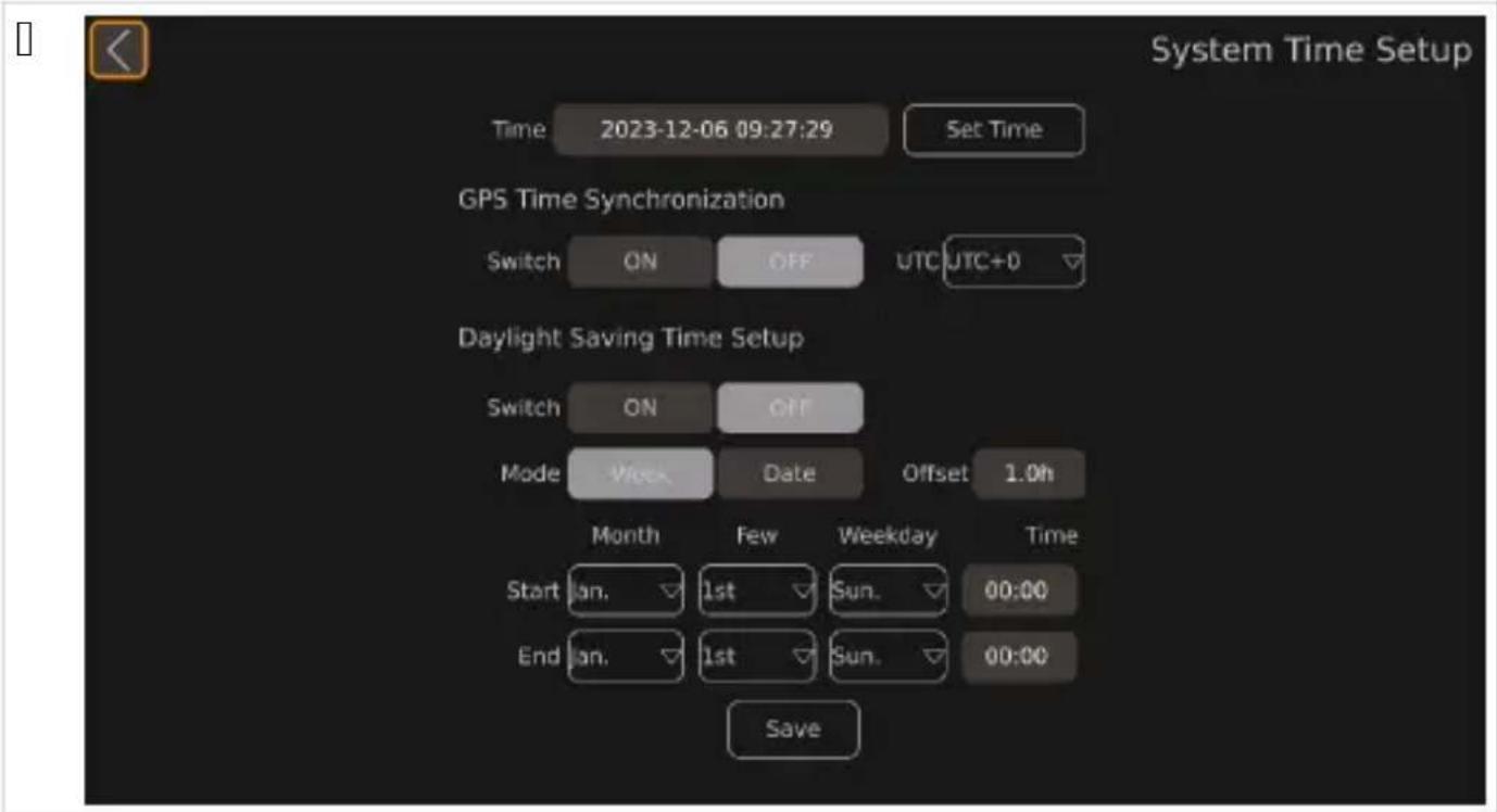
Q. Iz lopite monitor.
natural_image
Illustration of two delivery trucks with arrows indicating movement or loading, no text or symbols presentTP3 , 0i:i,) area camerel, r
natural_image
Diagram of an electronic device showing cable connector and internal port connections (no text or symbols)
natural_image
Diagram of a mechanical device with a lever and cable, showing motion direction (no text or symbols)TP6 I) tr, d1cerea 1) 1i card SD
natural_image
Line drawing of a car interior showing a monitor mounted on the side of a vehicle, with no visible text or symbols.U Utili0area
H<меBe:e п67ече и>ф6Вм<циА ; < В<C6:<:< 7 В4567689:76:6 ; < 56>фигуВиВ
N Ин67р"кц55 з: ' 8зоп: 6но67
4п: зв: й78 5н67р" кц5578 з: ' 8зоп: 6но67 5 пр8Ап56: н5я7: V 5зА: А8н5 о7 про5звОА578ля н: пр8возно7о 6р8А67во 5 68рв5з578Р
4п: зв: й78 пр5лож59578 з: конов5 р: зпор8А' 5Р

ОПА4НО4ТЛ Оп: 6но67 о7☐8к6плоз5я
Не946СВ<;А7<>е:6 91:е; и пВеУупВеж8е>иА ще 867е8е 8619м4В: или 9еВи6; >6 ><В<>А7<>е.
K<меВ<:< >е 6976С6ж8<7< 768<ч< 6: ;<84лже>ие:6 ;< гВиж< пВи шбфиВ<>е.
B68<ч4: 69:<7< и; цАл6 6:г676Be>; <упВ<7ле>ие:6 >> пВе76; >6:6 9Be89:76P; < и; п4л>e>ие:6 << ; <84лже>иА:<< ; < п4:>> Се; 6п<9>69: и ; < 9п<; 7<>е:6 >> ; <56>67и:е и; и957<>иА; < п4:>> Се; 6п<9>69:.

| No Ko9пон8н7 Кол5ч867во |
| Q K<меВ< V |
| I К6>:В6леВ Q |
| T Ди9:<>ци6>>6 упВ<7ле>ие Q |
| V И>фВ<чеВ7е> пВием>и5 QK C74В; 7<щ 5<Сел ; < пBe76; >6:6 9Be89:76 Q |
| W C74В; 7<щ 5<Селе> 56мпле5: ; < 5<меВ<:< Q |
| X У>и7еВ9<ле> 974В; 7<щ 5<Сел Q |
| Y О-пВ49:e>и V |
| Z K<Сел ; < 974В; 7<e >< м6>и:6В Q |
6 Пр5н: Ал8жно675
H<лич>и 5<:6 пВи><8леж>69:и b>e19< 75люче>и 716Сх7<:< ><1869:<75<:<cd
| Ф”нкц5я Оп56: н58 | |
| Calibrate C484Вж< В4567689:76:6 ;< 5<лиСВиВ<>е >< 9и9:ем<:< 6: 5<меВи. | |
| Surround View C484Вж< В4567689:76:6 ;< ><9:В6й5< > < 656л>иА и; гле8. | |
| Time Setup C484Вж< В4567689:76:6 ;< ><9:В6й5< > < 7Веме:6. | |
| Adas Setup C484Вж< В4567689:76:6 ;< 9и9:ем<:< ;< 6:5Ви7<>е >< пешех68ци. | |
| DVR Setup C484Вж< В4567689:76:6 ;< ><9:В6й5< > < 7и8е6;<пи9и:е. | |
[ ]
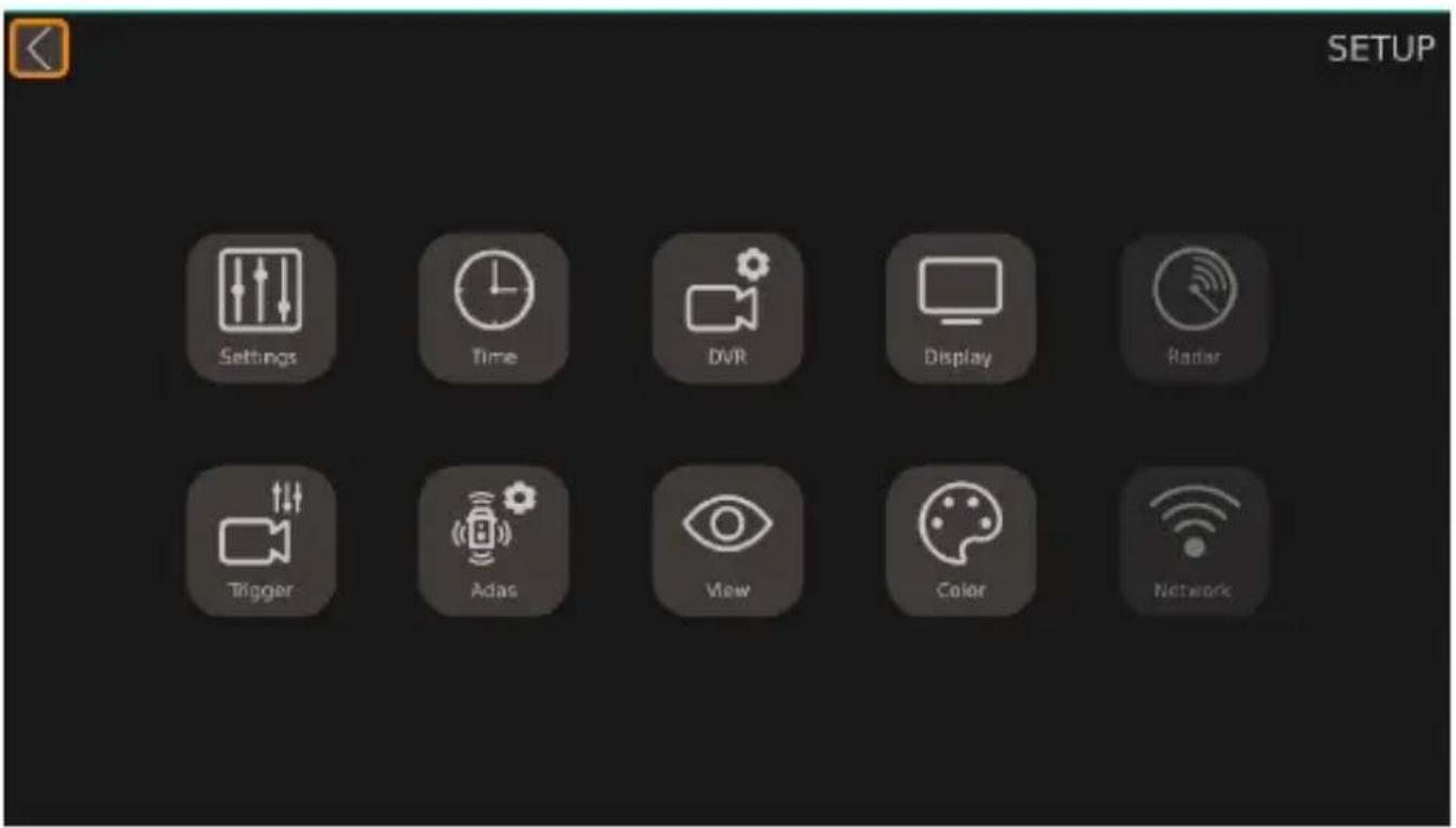
| П: р: 987ър Оп56: н58 | |
| Settings C484Вж< 69>67>и:е ><9:В6й5и. | |
| Time C484Вж< ><9:В6й5и:е ; < 7Веме. | |
| DVR C484Вж< ><9:В6й5и:е ; < цифВ67 7и8е6;<пи9. | |
| Display C484Вж< 6Сщи:е ><9:В6й5и ; < п65<; 7<>иА и; гле8 >< 5<меВ<:<. | |
| Radar He e ><лич>6. | |
| Trigger C484Вж< ><9:В6й5и:е ; < п65<; <>6:6би:ес и; 6СВ<же>невАс >< 5<меВ<:<Р 56г<:6 9е п6А7и 9иг><л ;;<8ей9:7<>е. | |
| Adas C484Вж< ><9:В6й5<:< >" das? 75лючи:ел>6 ><9:В6й5и:е ; < 9и9:ем<:< ; < 6:5Ви7<>е >< пешех68-ци эDL Sc. | |
| View C484Вж< ><9:В6й5и:е ; < и; гле8< ,,ВиСеш56 656qP В<; 8ели:ел><:< 9п696C>69: >< и; 6СВ<же>ие- :6 >< 5<меВ<:< и и; гле8< 6: 6гле8<л6:6 ; < ; <8>6 7иж8<>е. | |
| Color C484Вж< ><9:В6й5и:е ; < В<; 8ели:ел><:< 9п696C>69: >< ц7е:67е:е. | |
| Network He e ><лич>6. |
[ ]
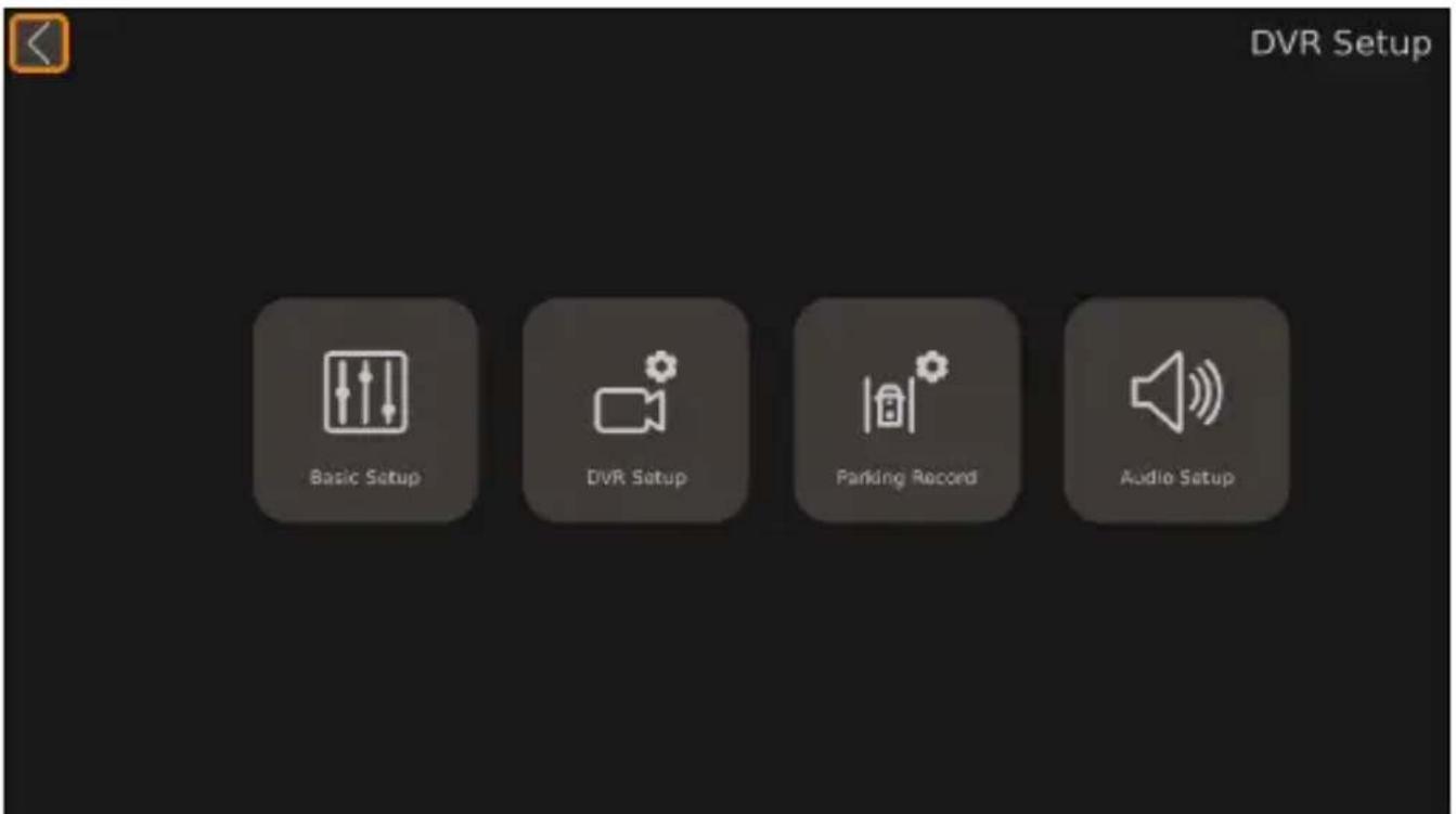
| П: р: 987ър Оп56: н58 | |
| Automatic Calibration | С484Вж< ><9:В6й5и:е ;< 5<лиСВиВ<>е >< 9и9:ем<:< 6: 5<меВи. |
| Calibration File | С484Вж< фу>5ции:е ;< е59п6В:иВ<>е и имп6В:иВ<>е >< ф<йл67е ;< 5<лиСВиВ<>е 54м и 6: 56м- пю:4В. |
| Vehicle Type C484Вж< ><9:В6й5и:е ;< :ип< пВе76;>6 9Ве89:76. | |
| Surround View C484Вж< ><9:В6й5и:е ;< 4г4л< >< пВип65Ви7<>е и ;<6Си5<лАщ<:< ; 6>< ;< гле8<>е. | |
| Parking Line C484Вж< ><9:В6й5и:е ;< ли>ии:е ;< п<В5иВ<>е. | |
| 3D Perspective | С484Вж< 6Сщи:е ><9:В6й5и ;< TL и;гле8 b><лич>и 9<м6 56г<:6 e <5:и7иВ<>TL и;гле8с. |
| Back View Perspective | С484Вж< ><9:В6й5и:е ;< TL и;гле8 ;< 5<меВ<:< ;< 6СВ<:>6 7иж8<>е t><лич>и 9<м6 пВи <5:и7и- В<>е >< TL и;гле8с. |
| 3D Display Adjust | С484Вж< ><9:В6й5и:е ;< и;гле8< 6: п:ичи п6гле8 t><лич>и 9<м6 56г<:6 e <5:и7иВ<>TL и;гле8с. |
[ ]

natural_image
Illustration of two delivery trucks with arrows indicating movement or loading, no text or symbols presente MA9:6:6>
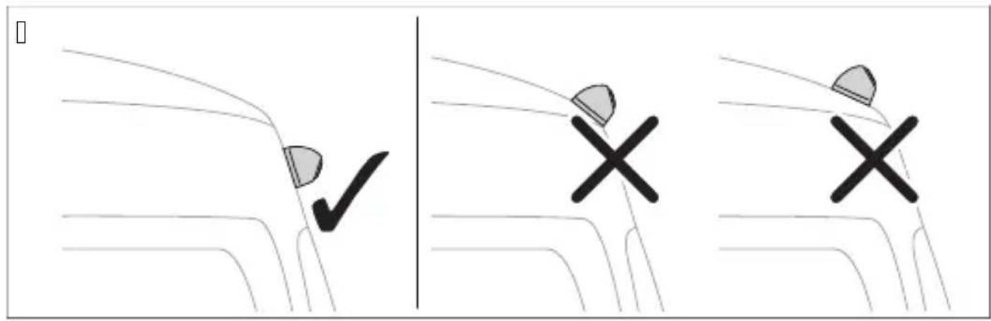
natural_image
Diagram of an electronic device showing cable connector and internal components (no text or symbols)
| Д87: йл Оп56: н58 | |
| Q | f " ' 7x68 >e 9e и; п6л; 7 |
| I | |
| T U" L " U b>e 9e и; п6л; 7 | |
| V f aBS y>и7eB9<ле> 7и8е6 и; x68 b56мп6; и:e>c | |
| K C74В; 7<e >< " | L м6>и:6В | |
| W K<Сел ;< 974В; 7<e >< м6>и:6В | |
| X . SB 7x68 | |
| Y Micro . SB >e 9e и; п6л; 7 | |
| Z 3<8ей9:7<щи 5 | |
| QJ ЧеBe> щеп9ел b,,Front f " Мард ПВе8>< 5 | |
| QQ ЧеBe> щеп9ел b,,oei f " Мард ЛА7< 5 | |
| QI ЧеBe> щеп9ел b,,Uight f " Мард ДА9>< 5 | |
| QT ЧеBe> щеп9ел b,,Uear f " Мард К<meB< ;< 6СВ<:>6 7иж8<e | |
| QV И>фВ<чеВ7е> пВием>и5 | |
| QK К6>:В6леВ | |
| bn | К<фа7 ;<8ей9:7<щ 5<Сел b,,NUIMs W" UL qcd C74В; 7<e 54м п6л6жи:ел>иА 5<Сел >< 97е:ли><:< ;<8e> x68.К6г<:6 е 75люче>< пВе8<75< ;< ;<8e> x68Р 56>:В6леВ4: и 5<меВ<:< ;< 6СВ<:>6 7иж8<e 9е<5:и7иВ<: чВе; :6; и 5<Сел. |
| bu | Си> ;<8ей9:7<щ 5<Сел b,,NUIMs L UIMMRUqcd Вх68 ;< упВ<7лА7<щ 9иг><л ;< п65<;7<e >< и; гле-8< 6: п:ичи п6гле8 >< цАл e5В<> b QI 1а 9иг><лс. |
| p 36;67 ;<8ей9:7<щ 5<Селд И; x68 ;< 56>:В6ле> 9иг><л ;< 75люч7<e >< м6>и:6В b QI 1а 9иг><лс. | |
| wh | БАл ;<8ей9:7<щ 5<Сел b,,NUIMs oqcd C74В; 7<e 54м п6л6жи:ел>иА 5<Сел >< ле7иА миг<ч.К6г<:6 ле7иА: миг<ч e <5:и7иВ<>Р 56>:В6леВ4: и 946:7e:><:< 5<меВ< 9е <5:и7иВ<: чВе; :6; и 5<Сел. |
| ye | Ж4л: ;<8ей9:7<щ 5<Сел b,,NUIMs Uqcd C74В; 7<e 54м п6л6жи:ел>иА 5<Сел >< 8e9>иА миг<ч.К6г<:6 8e9>иА: миг<ч e <5:и7иВ<>Р 56>:В6леВ4: и 946:7e:><:< 5<меВ< 9е <5:и7иВ<: чВе; :6; и 5<Сел. |
| b ЧеBe> 5<Сел a,,M' L qcd BB4; 5< 9 м<9< b5лем< TQc | |
| rd | ЧеВ7е> 5<Сел b,,L f QI mTl a qcd C74В; 7<e 54м п6л6жи:ел><:< 5лем< b5лем< TJ c >< п69:6А>>иА<5умул<:6В. П6; 76лА7<Р ><Be8 9 8Byr6:6Р ;<п<ме:A7<e >< 8<:< и ч<9 bфу>5циА ;< ;<пи97<ес. |
| ye Ж4л: 5<Сел b,,,f f qcd C74В; 7<e 54м ;<п<л7<e:6 " f f b5лем< QKc. | |
natural_image
Diagram of a mechanical device with a lever and cable, showing motion direction (no text or symbols)W. M<B5uB<й:e 6:76Ви:e ;<м6>:<ж>и:е 7и>:67е.

X. C7<ле:е 5<меВ<:<.
Y. ПВ6Сий:е I 6:76В<;<ø TPVImm 956С<:<><5<меВ<:<.

Z. H<96че:е 5<Сел< >> 5<меВ<:< 54м 74:Веш>69::<< пBe76;>6:6 9Be89:76.
QJ . 3<7ий:е 5<меВ<:< и 956С<:< >> 5<меВ<:<Р 5<:6 и; п6л; 7<:е 75люче>и:е 9<м6>

natural_image
Line drawing of a car interior showing a monitor mounted on the side of a vehicle, with no visible text or symbols.- ПВи5Вепе:е и>фВ<чеВ7е>иА пВием>и5 9 869:<7е><:<87у9:В<>><9<м6;<леп7<щ<ле>:<.
GO P: ' o7:
И; п6л; 7<й:е 8и9:<>ци6>>6:6 упВ<7ле>ие ир <56 им<р Су:6>и:е >< м6>и:6В< или 9е>; 6В>иА е5В<>р ; < 8<упВ<7лА7<:е и ><9:В6й7<:е 9и9:ем<: < 6: 5<меВи в7иж:е Ди9:<>ци6>>6 упВ<7ле>ие >< 9:В<>иц< XI Qс. Сп<; 7<й:е и>9:Ву5ции:е >< пВ6и; 768и:елА >< м6>и:6В<.

УКА„АНИЕ
B4; м6ж>6 е м6>и: 6В4: 8< им< п6-м<л56 Су: 6>и 6: 8и9:<>ци6>>6: 6 упВ<7ле>ие. С Су: 6>и:е < м6>и: 6В< им< п6-м<л56 6пции ; < В<С6:< и ВегулиВ<>е > < 9и9:ем<:< 6: 5<меВи.
К6г<:6 6:7<ВА:е или ВегулиВ<:е ><9:В6й5и:е ^р мбже 8< 6:>eme >А56л56 9е5у>8и ^р 865<:6 9и9:ем<:< 6: 5<меВи ; <Вe8и и и; п4л>и ><9:В6й5и:е.
3 Se, t1d d, k1me) did

oisateavet asutamise ohta vaada e seadistusjuhendist aadressil _r.dometic.com/beaeYa.
N ( F1t1sj1Fised
tärEiEe smid1ki t, , tja ) i) E -, litat1d töök, dade esitat1d , F1t1sj1Fiseid ja eri) m1deidP tärEiEe keFti- aid miE1s), rmeP

( H!L laF-at1s, Ft
H( IA! USL' iEast1s, Ft
natural_image
Illustration of two delivery trucks with arrows indicating movement or loading, no text or symbols presentTP3 Kaamerate DaiE1 tami) e
natural_image
Diagram of an electronic device showing cable connections to a connector with ports and connectors (no text or symbols present)
natural_image
Diagram of a mechanical device with a lever and cable, showing motion direction (no text or symbols)TP6 SD-kaardi sisestami) e
Q. /eera e SL - aardi ate juhtseadise üljest lahti.

natural_image
Line drawing of a car interior showing a monitor mounted on the side of a vehicle, with no visible text or symbols.| . /innitage in'rapuna-vastuvôtja omple tis oleva ahepoolse leeplindiga.
TPT Kaamerate elektriBFe) d1 se l, , mi) e

! ÄHELE ANUL KaFj1st1ste, Ft
U Kas1 tami) e
natural_image
Illustration of two delivery trucks with arrows indicating movement or loading, no text or symbols presentnatural_image
Diagram of an electronic device showing cable connector and internal port connections (no text or symbols)
natural_image
Diagram of a mechanical device with a lever and cable, showing motion direction (no text or symbols)natural_image
Line drawing of a car interior showing a monitor mounted on the side of a vehicle, with no visible text or symbols.U Λειτουργία
| NrP K, mD,) e) tas Kiekis |
| Q /amera V |
| I aaldi lis Q |
| T ' uotolinio valdymo pultas Q |
| V IU imtuvas Q |
| K Nransporto priemonøs prijungimo abelis Q |
| W Jungiamasis virvøs rin inys amerų abeliams Q |
| X . niversalus prijungimo abelis Q |
| Y Sandarinimo ) iedai V |
| Z Monitoriaus prijungimo abelis Q |
QPH riedai


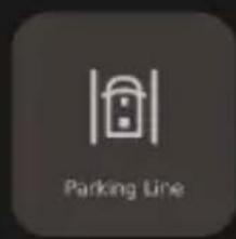

natural_image
Icon representing a 3D perspective with a cube and control arrows, no text or symbols present.

[ ]

natural_image
Illustration of two delivery trucks with arrows indicating movement or loading, no text or symbols presentnatural_image
Diagram of an electronic device showing cable connector and internal components (no text or symbols)
| K, mD, ) e) tas ADrašymas | |
| Q | f '' jvestis bnenaudojamac |
| I | |
| T U" L " U tnenaudojamac | |
| V f aBS universalioji vaizdo iGvestis osud∅tin∅c | |
| K " I L monitoriaus jungtis | |
| W Monitoriaus prijungimo abelis | |
| X . SB jvestis | |
| Y „Micro . SBq tnenaudojamac | |
| Z Daleidi lio abeliai | |
| OJ Juodas iGtu as b,,Front f " Mqcd prie in∅ amera | |
| QQ Juodas iGtu as b,,oei f " Mqcd airioji amera | |
| QI Juodas iGtu as b,,Uight f " Mqcd deGinioji amera | |
| QT Juodas iGtu as b,,Uear f " Mqcd galinio vaizdo amera | |
| QV IU imtuvas | |
| QK aaldi lis | |
| bn | Uudas paleidi lio abelis b,,NUIMs W" UL qcd jungtis su atbulin∅s eigos ) ibinto teigiamu abeliu. Ijungus atbulin∅s eigos pavarąP per Gį abelį sua tyvinamas valdi lis ir galin∅ amera. |
| bu | MØlynas paleidi lio abelis b,,NUIMs Rt NR' L qcd valdymo signalo įvestisP s irta rodyti vaizdą iG pau Gčio s ryd) io visame e rane b QI la signalasc. |
| p Uausvas paleidi lio abelisd valdymo signalo iGvestis monitoriui ijungti b QI la signalasc. | |
| wh | Baltas paleidi lio abelis o,,NUIMs oqcd jungtis su airiojo posū io ) ibinto teigiamu abeliu. Ijungus airiojo posū io ) ibintąP per Gį abelį sua tyvinamas valdi lis ir atitin ama amera. |
| ye | Meltonas paleidi lio abelis b,,NUIMs Uqcd jungtis su deGiniojo posū io ) ibinto teigiamu abeliu. Ijungus deGiniojo posū io ) ibintąP per Gį abelį sua tyvinamas valdi lis ir atitin ama amera. |
| b Juodas abelis b,,M' L qcd jungtis su i) eminimu bTQ gnybtasc | |
| rd | Uaudonas abelis b,,L f QI mTI aqcd jungtis su nuolatiniu teigiamu a umuliatoriaus gnybtu oTJ gnybtasc. Be itų daly uP leid) ia iGsaugoti datą ir lai ą braGytuvo ūun cijac. |
| ye Meltonas | abelis b,," f f qcd jungtis su " f f u) degimu bQK gnybtasc. |
natural_image
Diagram of a mechanical device with a lever and cable, showing motion direction (no text or symbols)W. Da) ym∅ ite angas tvirtinimo var) tams.

X. IGim ite amera.
Y. IGgre) ite | ∅ TPVImm angas ameros lai i liui.

Z. Draves ite ameros abelj i transporto priemonøs vidu.
Q]. Drisu ite amerą ir ameros lai i li naudodami patei tus savigrę) ius var) tus arba MT S I J mm srieginius var) tus.

| . Id∅ ite Q arba | SL orteles.
T. Drisu ite SL orteløs dangtelj prie valdi lio.
TPS IR imt1-, m,) ta-imas
natural_image
Line drawing of a car interior showing a monitor mounted on the side of a vehicle, with no visible text or symbols.U Na1d, jimas
v Uodoma Password Setup.
- Ne sto lau e Current ives ite seną slapta) odį.
T. Ne sto lai e New ives ite naują slapta) odj ir paspaus ite Confirm .

AS! A2A
G S- arīE as DieOīmes
DapildinFormEciju par izmantoGanu s atiet onfigurEcijas pamEcFbE vietnē r.dometic.com/beaeYa.
N Dr, šīKas), rādes
2RĪDINĀtUMSL!ra1m1 risks
NrP Detaļa Da1d01ms
Q /amera V
| NrP Detaja Da1 d01 ms |
| I Uegulators Q |
| T NElvadFbas pults Q |
| V InČrasar anais uztvērējs Q |
| K NransportlFdze za savienojuma vads Q |
| W SavienoGanas vads ameru abešiem Q |
| X . niversElais savienojuma vads Q |
| Y BlÍvgredzeni V |
| Z Monitora savienojuma vads Q |
QPH aDild1 Dieder1 mi
L etaas ^p as pieejamas E papildu piederumi bnav ie aautas piegEdes omple tEcijEc
6 ared0Ctais i0ma) t, ša) as mCrkis
| F1) kcijas ADraksts | |
| Calibrate Ietver pamEcfbu par ameru sistēmas alibrēGanu. | |
| Surround View Ietver norEdfjumus par TWJ grEdu s ata iestatīGanu. | |
| Time Setup Ietver pamEcfbu par lai a iestatīGanu. | |
| Adas Setup Ietver pamEcfbu par gEjēju onstatēGanas sistēmu. | |
| DVR Setup Ietver pamEcfbu par video iera stu iestatīGanu. | |
[]

natural_image
Illustration of two delivery trucks with arrows indicating movement or loading, no text or symbols presentnatural_image
Diagram of an electronic device showing cable connector and internal port connections (no text or symbols)
| Eleme) ts ADraksts | |
| Q | f '' ieeja onetie izmantotac |
| I | |
| T U" L " Utnetie izmantotsc | |
| V f aBS universEla video izeja o ompozfts signElsc | |
| K " I L monitora savienojums | |
| W Monitora savienojuma vads | |
| X . SB ieeja | |
| Y Micro . SB onetie izmantotsc | |
| Z IedarbinEGanas abesi | |
| QJ Melns spraudnis bqFront f " Mr cd Drie GejE amera | |
| Eleme) ts ADraksts | |
| QQ Melns spraudnis bqoei f " Mrcd /reisEs puses amera | |
| QI Melns spraudnis bqUight f " Mrcd oabEs puses amera | |
| QT Melns spraudnis bqUear f " Mrcd " tpa aes ata amera | |
| QV Inôrasar anais uztvērējs | |
| QK Uegulators | |
| bn | Brūns palaiGanas abelis bqNUIMs W" UL rcd savienojums ar atpa aegaitas lu tura pozitīvo abeli.Ieslēdzot atpa aegaitas pErnesumuP ar GF abea palfdzību notie ontrollera un atpa aes ata a-meras a tivizēGana. |
| bu | Zils palaiGanas abelis bqNUIMs Rt DoRL rcd /ontrolējiet signEla ievadiP lai parEdftu augGs atupilne rEna re) FmE b QI 1a c. |
| p SErts palaiGanas abelisd /ontrolējiet signEla izvadi monitora ieslēgGanai b QI 1a signElsc. | |
| wh | Balts palaiGanas abelis bqNUIMs or cd Savienojums ar reisE indi atora pozitīvo abeli./ad ir a tivizēts reisais indi atorsP regulatoru un attiecFgo ameru a tivizēP izmantojot Go abeli. |
| ye | L zeltens palaiGanas abelis bqNUIMs Ur cd Savienojums ar labE indi atora pozitīvo abeli./ad ir a tivizēts labais indi atorsP regulatoru un attiecFgo ameru a tivizēP izmantojot Go abeli. |
| b Melns abelis bqM' L rcd Savienojums ar iezemējumu bizvads TQc | |
| rd | Sar ans abelis bqL f QI mTI ar cd Savienojums ar nepErtrau tu a umulatora pozitīvo polu bizvadsTJ c. f ita starpE eauj saglabEt datumu un lai u bregistratora 0un cijac. |
| ye L zeltens | abelis bq" f f rcd Savienojums ar " f f aizdedzi bizvads QKc. |
natural_image
Diagram of a mechanical device with a lever and cable, showing motion direction (no text or symbols)NEMIE! ' ĘRĀL ārkarša) as risks
' euzstEdiet regulatoru vietEP uru apspFd tieGa saules gaisma.

IEWIME
| . Ievietojiet Q vai | SL artes.
T. Dies rūvējiet SL artes pErsegu pie ontrollera.
natural_image
Line drawing of a car interior showing a monitor mounted on the side of a vehicle, with no visible text or symbols.U EksDl1 atācija
Izmantojiet tElvadFbas pulti un monitora pogas vai s Eriene rEnu bja pieejamicP lai izmantotu un noregulētu ameru sistēmu bs atiet sadau NEIvadFbas pults lpp.IYXTc.
dometic.com/sales-offices


