
PerfectView CAM 440CS - Rear Camera DOMETIC - Free user manual and instructions
Find the device manual for free PerfectView CAM 440CS DOMETIC in PDF.

User questions about PerfectView CAM 440CS DOMETIC
0 question about this device. Answer the ones you know or ask your own.
Ask a new question about this device
Download the instructions for your Rear Camera in PDF format for free! Find your manual PerfectView CAM 440CS - DOMETIC and take your electronic device back in hand. On this page are published all the documents necessary for the use of your device. PerfectView CAM 440CS by DOMETIC.
USER MANUAL PerfectView CAM 440CS DOMETIC
EN Camera Installation and Operating Manual......8
© 2025 Dometic Group. The visual appearance of the contents of this manual is protected by copyright and design law. The underlying technical design and the products contained herein may be protected by design, patent or pending patent. The trademarks mentioned in this manual belong to Dometic Sweden AB. All rights are reserved.
natural_image
Diagram of a mechanical device with a curved pipe and housing, showing motion direction (no text or symbols)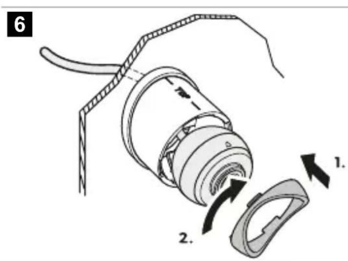
7
natural_image
Diagram of a cylindrical device with internal flow arrows indicating direction (no text or symbols)8
9
flowchart
graph TD
    A["1"] --> B["2"]
    C["3"] --> D["4"]
    E["5"] --> F["bk"]
    G["6"] --> H["od"]
    I["7"] --> J["bk"]
    K["8"] --> L["ye, RCA"]
12
CVBS

natural_image
Simple line drawing of a cylindrical object with a curved filament extending from it, labeled 'bu' in the top-left corner (no other text or symbols)AHD

natural_image
Illustration of a hairpin being inserted into a cylindrical object with scissors, no text or symbols presentEnglish
1 Important notes....8
2 Explanation of symbols....8
3 Safety instructions....9
4 Scope of delivery....10
5 Accessories....11
6 Intended use....11
7 Technical description....11
8 Installation....11
9 Operation....13
10 Cleaning and maintenance....13
11 Disposal....14
12 Warranty....14
13 Technical data....14
1 Important notes
Please read these instructions carefully and follow all instructions, guidelines, and warnings included in this product manual in order to ensure that you install, use, and maintain the product properly at all times. These instructions MUST stay with this product.
By using the product, you hereby confirm that you have read all instructions, guidelines, and warnings carefully and that you understand and agree to abide by the terms and conditions as set forth herein. You agree to use this product only for the intended purpose and application and in accordance with the instructions, guidelines, and warnings as set forth in this product manual as well as in accordance with all applicable laws and regulations. A failure to read and follow the instructions and warnings set forth herein may result in an injury to yourself and others, damage to your product or damage to other property in the vicinity. This product manual, including the instructions, guidelines, and warnings, and related documentation, may be subject to changes and updates. For up-to-date product information, please visit documents.dometic.com.
2 Explanation of symbols
A signal word will identify safety messages and property damage messages, and also will indicate the degree or level of hazard seriousness.

DANGER!
Indicates a hazardous situation that, if not avoided, will result in death or serious injury.

WARNING!
Indicates a hazardous situation that, if not avoided, could result in death or serious injury.

CAUTION!
Indicates a hazardous situation that, if not avoided, could result in minor or moderate injury.

NOTICE!
Indicates a situation that, if not avoided, can result in property damage.
3 Safety instructions
Observe the safety instructions and stipulations issued by the vehicle manufacturer and service workshops.
Observe the applicable legal regulations.

DANGER! Explosion hazard
Failure to obey these warnings will result in death or serious injury.
The camera does not release the driver from the duty of care when driving.
The driver remains fully responsible for driving the vehicle, for fulfilling the road safety obligations, and for complying with the statutory road safety requirements.

WARNING! Risk of injury
Failure to obey these warnings could result in death or serious injury.
This camera can be used by children aged from 8 years and above and persons with reduced physical, sensory or mental capabilities or lack of experience and knowledge if they have been given supervision or instruction concerning use of the device in a safe way and understand the hazards involved.
Secure the parts installed in the vehicle in such a way that they cannot become loose under any circumstances (sudden braking, accidents) and cause injuries to the occupants of the vehicle.
Do not install parts anywhere in the vehicle where an airbag may open. This can cause injury if the airbag deploys.Inadequate supply line connections can result in short circuits causing:
- Cable fires
• The airbag being triggered - Damage to electronic control devices
- Electrical malfunctions (turn signal, stoplight, horn, ignition, lights)

CAUTION! Risk of injury
Failure to obey these cautions could result in minor or moderate injury.
Secure any parts of the system concealed by the bodywork in such a manner that they cannot become loose or damage other parts or cables, or impair vehicle functions (steering, pedals, etc.).
Always follow the safety instructions of the vehicle manufacturer. Some work (e.g., on retention systems such as the airbag, etc.) may only be performed by qualified specialists.

NOTICE! Damage hazard
To prevent damage when drilling ensure that there is sufficient space on the other side for the drill head to emerge.
Deburr all drill holes and treat them with a rust-protection agent.
When working on the electrical system, the batteries must be separated from the vehicle ground. This applies to the main and additional batteries.When working on the following cables only use insulated cable lugs, plugs and tab sleeves: • 30 (direct input from positive battery terminal)
• 15 (connected positive terminal, behind the battery)
• 31 (return cable from the battery, ground)
- 58 (reversing light)
Do not use porcelain wire connectors.
Use a crimping tool to connect the cables.
Screw the cable when connecting cable 31 (ground).
- Screw the cable using a cable lug and lock washer to one of the vehicle's ground bolts or
- Screw the cable to the sheet metal body work using a cable lug and a self-tapping screw.
Ensure that there is a good ground connection.
If the battery is disconnected, all data stored in all volatile memory will be lost. Data may have to be reset. Follow the instructions of the vehicle manufacturer in this case. The instructions for making these settings can be found in the operating manual.
When testing the voltage in electrical cables only use a diode test lamp or a voltmeter. Test lamps with a bulb consume too much voltage which can damage the vehicle's electronic system.
When making electrical connections ensure the following:
• They are not kinked or twisted.
• They do not rub on edges.
- They are not laid in sharp-edged through-holes without protection.
Insulate all connections.
Secure the cables against mechanical stress with cable binders or insulating tape, e.g., to existing lines.
Follow the installation and operating manual for the monitor.
Do not open the camera.
Do not pull the cables.
Do not expose the cables to solvents such as benzene for long periods of time.
Do not use the cameras under water.
Install cables far enough away from hot or moving vehicle parts (exhaust pipes, drive shafts exhaust pipes, drive shafts, lights, blowers, heaters, etc.).
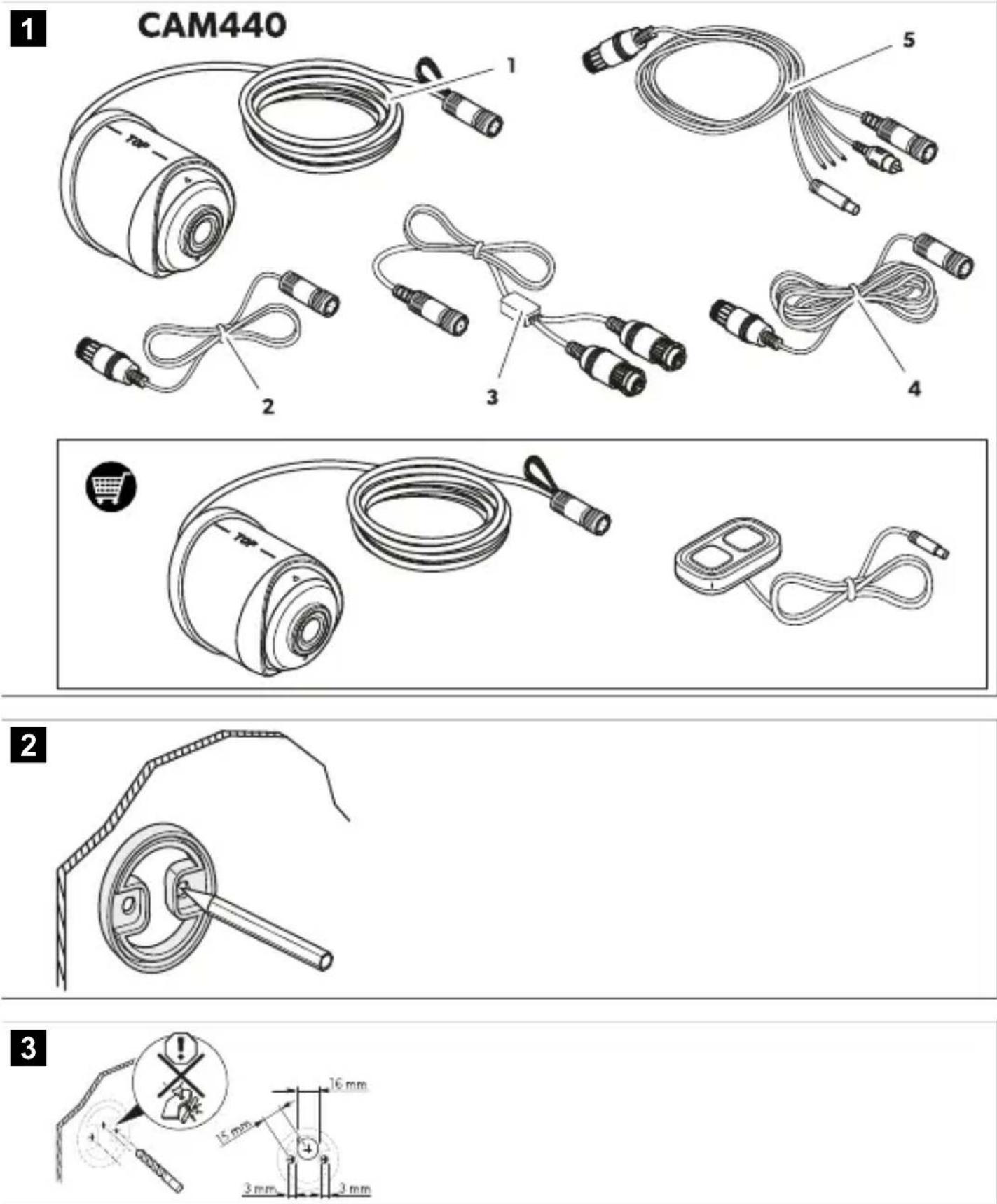
4 Scope of delivery
CAM440

Fig. 1 on page 3
| Item in figure Quantity Designation | |
| 1 1 Camera | |
| 2 1 Extension cable, 5 m | |
| 3 1 Y-adapter to camera | |
| 4 1 System cable, 20 m | |
| 5 1 Y-adapter to monitor | |
| -1 Installation and operating manual |
5 Accessories
Available as accessories (not included in the scope of delivery):
Component Ref. no.
Control switch CAM440SW 9620013722
Additional camera CAM440E 9620006605
6 Intended use
The camera is designed for use in vehicles. It can be used in rear view video systems to observe the space behind the vehicle from the driver's seat when maneuvering or parking. The camera does not release the driver from the duty of care when driving. The driver remains fully responsible for driving the vehicle, for fulfilling the road safety obligations and for complying with the statutory road safety requirements.
This product is only suitable for the intended purpose and application in accordance with these instructions.
This manual provides information that is necessary for proper installation and/or operation of the product. Poor installation and/or improper operation or maintenance will result in unsatisfactory performance and a possible failure.
The manufacturer accepts no liability for any injury or damage to the product resulting from:
- Incorrect installation, assembly or connection, including excess voltage
- Incorrect maintenance or use of spare parts other than original spare parts provided by the manufacturer
• Alterations to the product without express permission from the manufacturer - Use for purposes other than those described in this manual
Dometic reserves the right to change product appearance and product specifications.
7 Technical description
The camera is equipped with a Megapixel sensor and an integrated microphone encased in a waterproof housing and transmits image and sound to a monitor via a connection cable.
The camera provides a rear view of more than 170^ . An optional control switch can be used to switch between a rear view of more than 170^ and a far view of more than 100^ .
- The rear view of more than 170^ shows the area directly behind the vehicle. It is activated when you engage reverse gear.
- The far view of more than 100^ shows the space behind the vehicle as if you were looking through a rear window. It is switched on when you are not reversing.
An additional camera of the same type can be mounted in a different position on a large RV or truck. This enables visual monitoring of areas that cannot be covered by one single camera. An optional control switch can be used to switch between the cameras and between a rear view of more than 170^ and a far view of more than 100^ .
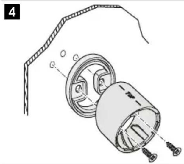
8 Installation
8.1 Fitting the camera
- Mark the camera seal on the installation location.

Fig. 2 on page 3
- Drill the screw holes and the through-hole for the camera connection cable.

Fig. 3 on page 3
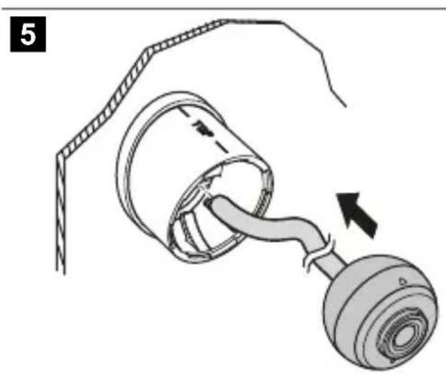
- Screw the holder to the vehicle.

Fig. 4 on page 4
- Insert the camera into the holder.

Fig. 5 on page 4
- Fix the camera with the bayonet fitting.

Fig. 6 on page 4
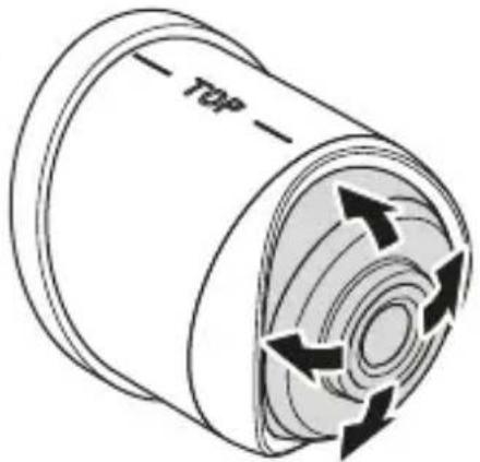
- When the installation is finished, adjust the camera ball by pressing it slightly into the holder and turn it as desired.

Fig. 7 on page 5
8.2 Connecting the camera
Depending on the chosen configuraton, different connections are required.
- Connect the camera according to the configuration:
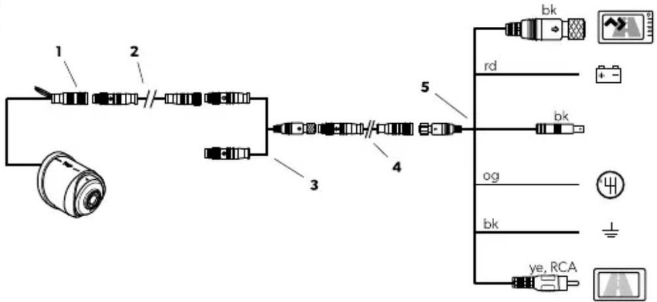
a) Rear view camera

Fig. 8 on page 5
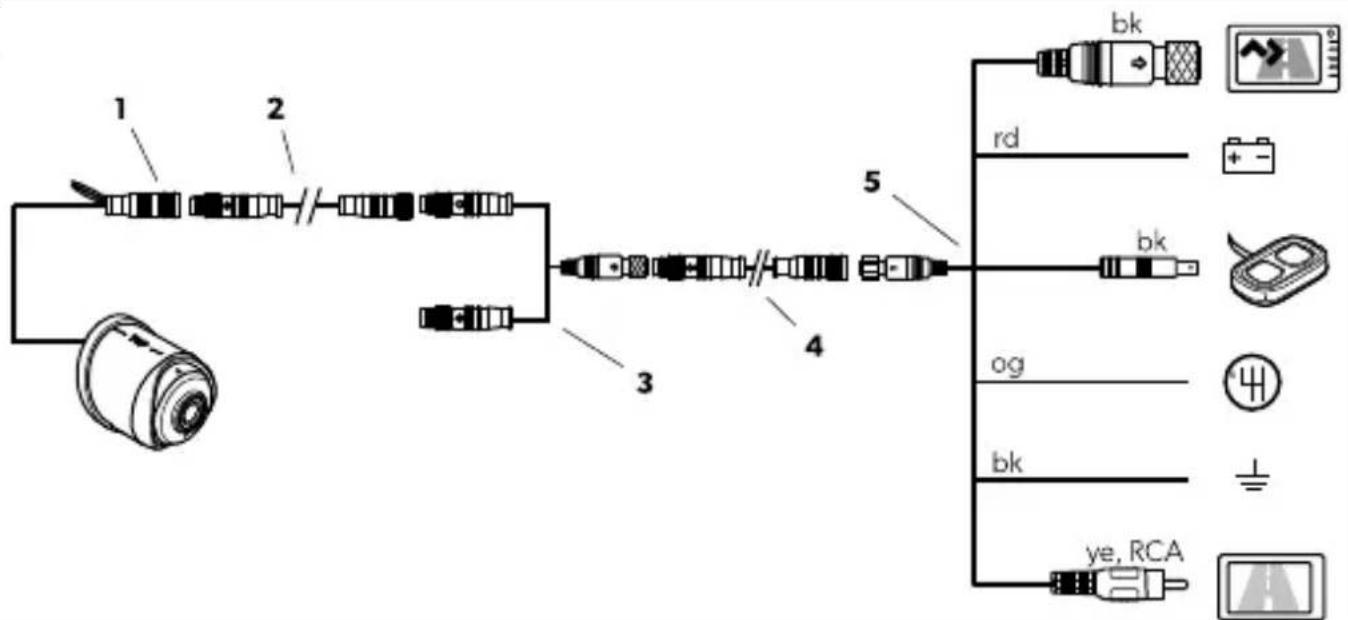
b) Rear view camera and control switch

Fig. 9 on page 5
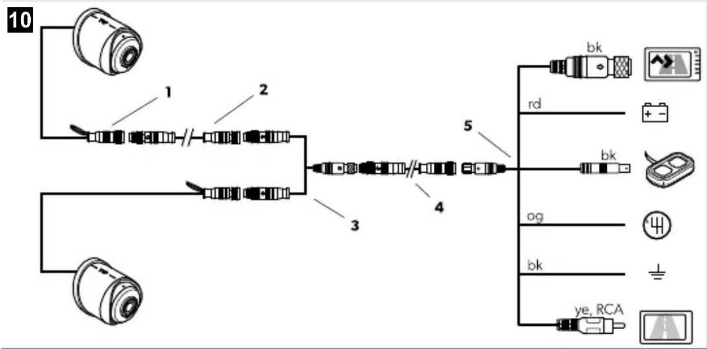
c) Rear view camera, additional camera and control switch

Fig. 10 on page 6
- Observe the key to the wiring diagrams:
| No. Designation Description | ||
| 1 Camera – | ||
| 2 Extension cable, 5 m – | ||
| 3 Y-adapter to camera Connection of additional camera | ||
| 4 System cable, 20 m – | ||
| 5 Y-adapter to monitor | 6-pin screw type connector (bk) Connection to Dometic monitor | |
| Red wire (rd) Connection 12 V / 24 V to ignition in case no Dometic monitor is applied | ||
| Connector (bk) Connection to control switch (optional) | ||
| Orange wire (og) Connection to reverse gear | ||
| No. Designation Description | |||
| Black wire (bk) Connection to ground in case noDometic monitor is applied | |||
| Connector (ye, RCA) Video output for universal monitor connection | |||
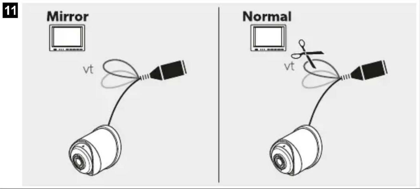
- Choose from further options:
a) Keep the closed loop (vt) for a mirrored picture or cut the loop (vt) for a normal picture on the monitor.

Fig. 11 on page 6
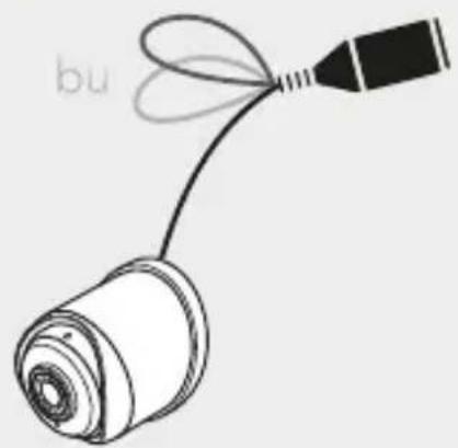
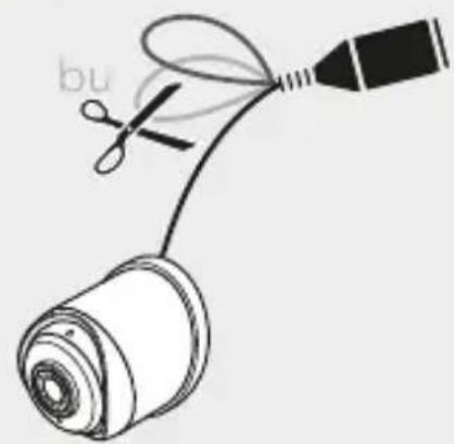
b) Keep the closed loop (bu) for the CVBS video format or cut the loop (bu) for the AHD video format.

Fig. 12 on page 7
8.3 Setting the camera into operation
- When the camera is connected to the monitor, check the function of the camera.
- Align the camera using the image on the monitor to help you.
√ The monitor image should show the rear or the bumper of the vehicle at the bottom edge of the screen. The middle of the bumper should be in the middle of the screen.
- Adjust the settings for contrast and brightness on the monitor.
9 Operation
9.1 Notes on using the camera
The camera is watertight. However, the seals on the camera cannot withstand a high-pressure cleaner. Therefore, you should observe the following instructions when handling the camera:
- Do not open the camera, as this impairs the watertightness and the function of the camera.
- Do not pull on the cables, as this impairs the watertightness and the function of the camera.
- The camera is not suitable for use under water.
10 Cleaning and maintenance

WARNING! Damage hazard
Never clean the device under running water or in dish water.
Do not use sharp or hard objects, abrasive cleaning agents or bleach during cleaning as these may damage the device.Occasionally clean the product with a damp cloth.
Regularly check live cables or wires fro insulation faults, breaks or loose connections.
11 Disposal

Place the packaging material in the appropriate recycling waste bins whenever possible. Consult a local recycling center or specialist dealer for details about how to dispose of the product in accordance with the applicable disposal regulations. Europe. The product can be disposed free of change.
12 Warranty
The statutory warthypenoid applies. If the product is defective, please contact the manufacturer's branch in your country (see domestic.com/disaler) or your retailer.
For repair and warranty processing, please include the following documents when you send in the device
• A copy of the receipt with purchasing date
- A reason for the claim or description of the fault
Note that self-re-pair or nonprofessional repair can have safety consequences and might void the warranty
13 Technical data
| CAM-40 | |
| Images error | 2 MP CMOS enabling AHD+ CVBS (switchable) |
| Video from at | AHD/ CVBS (PAI) switchable |
| Light sensitivity | < 0.5 μ |
| Field of view (FOM) | AHD D: 172^ ± 5^ H;165^ ± 5^ V;115^ ± 5^ CVBS: D: 172^ ± 5^ H;157^ ± 5^ V;105^ ± 5^ |
| Zoom FOV | AHD D: 105^ ± 5^ H;95^ ± 5^ V;58^ ± 5^ CVBS: D: 98^ ± 5^ H;85^ ± 5^ V;55^ ± 5^ |
Deutsch
7 Description technique
Kontrollbryter CAM440SW 9620013722
Ekstra kamera CAM440E 9620006605
dometic.com/sales-offices


