
PCM 7 - REV 3-2009 - Miter saw BOSCH - Free user manual and instructions
Find the device manual for free PCM 7 - REV 3-2009 BOSCH in PDF.



| Brand | BOSCH |
| Model | PCM 7 |
| Category | Mitre saw |
| Rated power input | 1100 W |
| Rated voltage | 230 V |
| Frequency | 50/60 Hz |
| No-load speed | 4800 rpm |
| Weight (according to EPTA 01/2003) | 8.0 kg |
| Protection class | II (double insulation) |
| Saw blade diameter | 190 mm |
| Blade thickness | 1.4 – 2.5 mm |
| Bore diameter | 30 mm |
| Horizontal mitre angle range | -46° to +46° |
| Vertical mitre angle range | 0° to 45° |
| Laser type | 650 nm, < 1 mW, class 2 |
| Sound pressure level | 93 dB(A) |
| Sound power level | 106 dB(A) |
| Dust extraction system | Integrated dust bag, connection for external vacuum cleaner (Ø 36 mm) |
| Clamp | Screw-type clamp, adaptable left or right |
| Safety device | Pendulum guard, emergency stop |
| Included accessories | Dust bag, clamp, 6 mm hex key, AAA batteries (2x) |
| Maximum workpiece dimensions (0°/0°) | 50 x 110 mm (height x width) |
| Minimum workpiece dimensions | 100 x 40 mm (length x width) |
| Maintenance | Regularly clean the protective guard and sliding roller; replace support plate if worn |
Frequently Asked Questions - PCM 7 - REV 3-2009 BOSCH
User questions about PCM 7 - REV 3-2009 BOSCH
0 question about this device. Answer the ones you know or ask your own.
Ask a new question about this device
Download the instructions for your Miter saw in PDF format for free! Find your manual PCM 7 - REV 3-2009 - BOSCH and take your electronic device back in hand. On this page are published all the documents necessary for the use of your device. PCM 7 - REV 3-2009 by BOSCH.
USER MANUAL PCM 7 - REV 3-2009 BOSCH
Power Tools Division
70745 Leinfelden-Echterdingen
Germany
www.bosch-pt.com
1609929 S46 (2009.03) PS/331 UNI
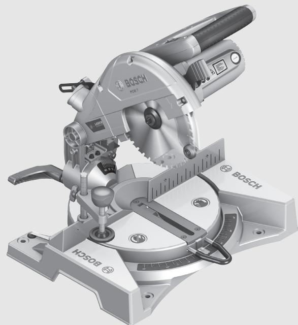
PCM 7

BOSCH
de Originalbetriebsanleitung en Original instructions fr Notice originale es Manual original pt Manual original it Istruzioni originali nl Oorspronkelijke gebruiksaanwijzing da Original brugsan sv Bruksanvisning i original no Original driftsinstruks
fi Alkuperäiset ohjeet el TpwoTOTUO odnyiwxphonc tr Original isletmet talimati pl Instrukcja oryginalna cs Puvodni navod k použivání sk Povodny navod na pouziti hu Eredeti használatiutasítás ru OpHnHaIbHoe pyKoBOaCT-BO IIO 3KcPiayatauIN uk OpnrHaIbHa iHCTpyKciJ3 ekTnayataqii
ro Instruetiuni originale bg OpnHaHa HnHCTpyKm sr Originalno uputstvo za rad sl Izvirna navodila hr Originalne upute za rad et Algupärane kasutusjuhend Instrukcijas originalida It Originalinstrukcija

2

4

6
1 609 929 S46 | (24.3.09)
Bosch Power Tools
8
German. 9
English. Page 22
French. Page 33
Spanish. 45
Portuguese. Page 58
Italian. 71
Dutch. 84
Danish. 96
Swedish. Page 107
Norwegian. Page 118
Finnish. 129
Greek. Page 140
Turkish. Page 153
Polish. Page 165
Czech. Page 177
Slovak. Page 188
Hungarian. Page 200
Russian. Page 212
Ukrainian. Page 225
Romanian. Page 238
Bulgarian. Page 250
Serbian. Page 263
Slovenian. Page 274
Dr. Egbert Schneider Senior Vice President Engineering
Dr. Eckerhard Strötgen Head of Product Certification
Robert Bosch GmbH, Power Tools Division D-70745 Leinfelden-Echterdingen Leinfelden, 25.03.2009
Assembly
General Power Tool Safety Warnings
WARNING
Read all safety warnings and all instructions. Failure to follow
the warnings and instructions may result in electric shock, fire and/or serious injury.
Save all warnings and instructions for future reference.
The term "power tool" in the warnings refers to your mains-operated (corded) power tool or battery-operated (cordless) power tool.
1) Work area safety
a) Keep work area clean and well lit. Cluttered or dark areas invite accidents. b) Do not operate power tools in explosive atmospheres, such as in the presence of flammable liquids, gases or dust. Power tools create sparks which may ignite the dust or fumes. c) Keep children and bystanders away while operating a power tool. Distractions can cause you to lose control.
2) Electrical safety
a) Power tool plugs must match the outlet. Never modify the plug in any way. Do not use any adapter plugs with earthed (grounded) power tools. Unmodified plugs and matching outlets will reduce risk of electric shock. b) Avoid body contact with earthed or grounded surfaces, such as pipes, radiators, ranges and refrigerators. There is an increased risk of electric shock if your body is earthed or grounded. c) Do not expose power tools to rain or wet conditions. Water entering a power tool will increase the risk of electric shock. d) Do not abuse the cord. Never use the cord for carrying, pulling or unplugging the power tool. Keep cord away from heat, oil, sharp edges and moving parts. Damaged or entangled cords increase the risk of electric shock.
e) When operating a power tool outdoors, use an extension cord suitable for outdoor use. Use of a cord suitable for outdoor use reduces the risk of electric shock. f) If operating a power tool in a damp location is unavoidable, use a residual current device (RCD) protected supply. Use of an RCD reduces the risk of electric shock.
3) Personal safety
a) Stay alert, watch what you are doing and use common sense when operating a power tool. Do not use a power tool while you are tired or under the influence of drugs, alcohol or medication. A moment of inattention while operating power tools may result in serious personal injury. b) Use personal protective equipment. Always wear eye protection. Protective equipment such as dust mask, non-skid safety shoes, hard hat, or hearing protection used for appropriate conditions will reduce personal injuries. c) Prevent unintentional starting. Ensure the switch is in the off-position before connecting to power source and/or battery pack, picking up or carrying the tool. Carrying power tools with your finger on the switch or energising power tools that have the switch on invites accidents. d) Remove any adjusting key or wrench before turning the power tool on. A wrench or a key left attached to a rotating part of the power tool may result in personal injury. e) Do not overreach. Keep proper footing and balance at all times. This enables better control of the power tool in unexpected situations. f) Dress properly. Do not wear loose clothing or jewellery. Keep your hair, clothing and gloves away from moving parts. Loose clothes, jewellery or long hair can be caught in moving parts.
g) If devices are provided for the connection of dust extraction and collection facilities, ensure these are connected and properly used. Use of dust collection can reduce dust-related hazards.
4) Power tool use and care
a) Do not force the power tool. Use the correct power tool for your application. The correct power tool will do the job better and safer at the rate for which it was designed. b) Do not use the power tool if the switch does not turn it on and off. Any power tool that cannot be controlled with the switch is dangerous and must be repaired. c) Disconnect the plug from the power source and/or the battery pack from the power tool before making any adjustments, changing accessories, or storing power tools. Such preventive safety measures reduce the risk of starting the power tool accidentally. d) Store idle power tools out of the reach of children and do not allow persons unfamiliar with the power tool or these instructions to operate the power tool. Power tools are dangerous in the hands of untrained users. e) Maintain power tools. Check for misalignment or binding of moving parts, breakage of parts and any other condition that may affect the power tool's operation. If damaged, have the power tool repaired before use. Many accidents are caused by poorly maintained power tools. f) Keep cutting tools sharp and clean. Properly maintained cutting tools with sharp cutting edges are less likely to bind and are easier to control. g) Use the power tool, accessories and tool bits etc. in accordance with these instructions, taking into account the working conditions and the work to be performed. Use of the power tool for operations different from those intended could result in a hazardous situation.
5) Service
a) Have your power tool serviced by a qualified repair person using only identical replacement parts. This will ensure that the safety of the power tool is maintained.
Safety Warnings for Chop and Mitre Saws
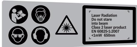
The machine is delivered with a warning label in German language (marked with the number 2 in the representation of the machine on the graphic page).
Before putting into operation for the first time, attach the supplied sticker in your national language over the German warning label.
- Secure the workpiece. A workpiece clamped with clamping devices or in a vice is held more secure than by hand.
- Keep your workplace clean. Blends of materials are particularly dangerous. Dust from light alloys can burn or explode.
- Never leave the machine before it has come to a complete stop. Cutting tools that are still running can cause injuries.
- Never use the machine with a damaged cable. Do not touch the damaged cable and pull the mains plug when the cable is damaged while working. Damaged cables increase the risk of an electric shock.
- Never make warning signs on the machine unrecognisable.
- Never stand on the power tool. Serious injuries can occur when the power tool tips over or when inadvertently coming into contact with the saw blade. Make sure that the guard operates properly and that it can move freely. Never lock the guard in place when opened.

- Keep hands away from the cutting area while the machine is running. Danger of injury when coming in contact with the saw blade.
- Never remove cutting remainders, wood chips, etc. from the sawing area while the machine is running. Always guide the tool arm back to the neutral position first and then switch the machine off. Guide the saw blade against the workpiece only when the machine is switched on. Otherwise there is danger of kickback when the saw blade becomes wedged in the workpiece. Operate the power tool only when the work area to the workpiece is clear of any adjusting tools, wood chips, etc. Small pieces of wood or other objects that come in contact with the rotating saw blade can strike the operator with high speed. Always firmly clamp the piece to be worked. Do not saw workpieces that are too small to clamp. Otherwise, the clearance of your hand to the rotating saw blade is too small. Operate the machine only for materials mentioned under "Intended Use". Otherwise, the machine can be subject to overload. If the saw blade should become jammed or when interrupting work, switch the saw off and hold the workpiece until the saw blade comes to a complete stop. Never attempt to remove the workpiece as long as the saw blade is in motion, otherwise kickback may occur. Determine and correct the cause for the jamming of the saw blade. Do not use dull, cracked, bent or damaged saw blades. Unsharpened or improperly set saw blades produce narrow kerf causing excessive friction, blade binding and kickback.
Always use saw blades with correct size and shape (diamond versus round) of arbor holes. Saw blades that do not match the mounting hardware of the saw will run eccentrically, causing loss of control. Do not use high speed steel (HSS) saw blades. Such saw blades can easily break. Do not touch the saw blade after working before it has cooled. The saw blade becomes very hot while working. Never operate the machine without the insert plate. Replace a defective insert plate. Without flawless insert plates, injuries are possible from the saw blade. Do not direct the laser beam at persons or animals and do not stare into the laser beam yourself, not even from a distance. This power tool produces laser class 2 laser radiation according to EN 60825-1. This can lead to persons being blinded. Do not allow children unsupervised use of the power tool with laser. They could blind other people. Do not replace the installed laser with another laser type. A laser that does not fit to this power tool could pose dangers for other persons.
Products sold in GB only: Your product is fitted with a BS 1363/A approved electric plug with internal fuse (ASTA approved to BS 1362).
If the plug is not suitable for your socket outlets, it should be cut off and an appropriate plug fitted in its place by an authorised customer service agent. The replacement plug should have the same fuse rating as the original plug.
The severed plug must be disposed of to avoid a possible shock hazard and should never be inserted into a mains socket elsewhere.
Symbols
The following symbols can be important for the operation of your power tool. Please memorise the symbols and their meanings. The correct interpretation of the symbols helps you operate the power tool better and more secure.
Symbol
Meaning

Wear a dust respirator.

Wear safety goggles.

Wear ear protectors. Exposure to noise can cause hearing loss.

- Do not direct the laser beam at persons or animals and do not stare into the laser beam yourself, not even from a distance. This power tool produces laser class 2 laser radiation according to EN 60825-1. This can lead to persons being blinded.
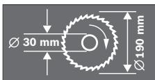
Observe the dimensions of the saw blade. The hole diameter must match the tool spindle without play. Do not use reducers or adapters.

Danger area! Keep hands, fingers or arms away from this area.

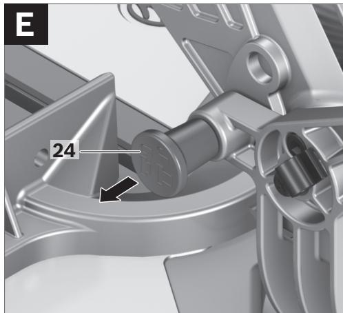
The transport safety-lock 24 enables easier handling of the machine when transporting to various working locations.
- Transport safety-lock 24 pushed completely inward: Securing the Machine (Transport Position)
- Transport safety-lock 24 pulled completely outward: Releasing the Machine (Working Position)
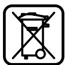
Only for EC countries:
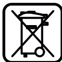
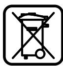
Do not dispose of power tools into household waste! According to the European Guideline 2002/96/EC for Waste Electrical and Electronic Equipment and its implementation into national law, power tools that are no longer usable must be collected separately and disposed of in an environmentally correct manner.
Functional Description

Read all safety warnings and all instructions. Failure to follow the warnings and instructions may result in electric shock, fire and/or serious injury.
Intended Use
The power tool is intended as a stationary machine for making straight lengthways and crossways cuts in wood. In this, mitre angles from -46° to +46° as well as bevel angles from 0° to 45° are possible.
The capacity of the power tool is designed for sawing hardwood and softwood.
Product Features
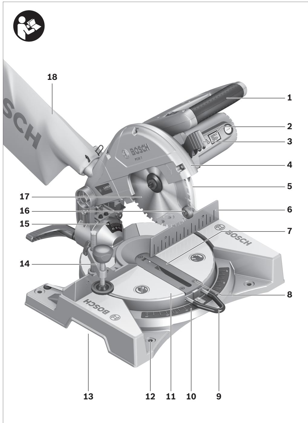
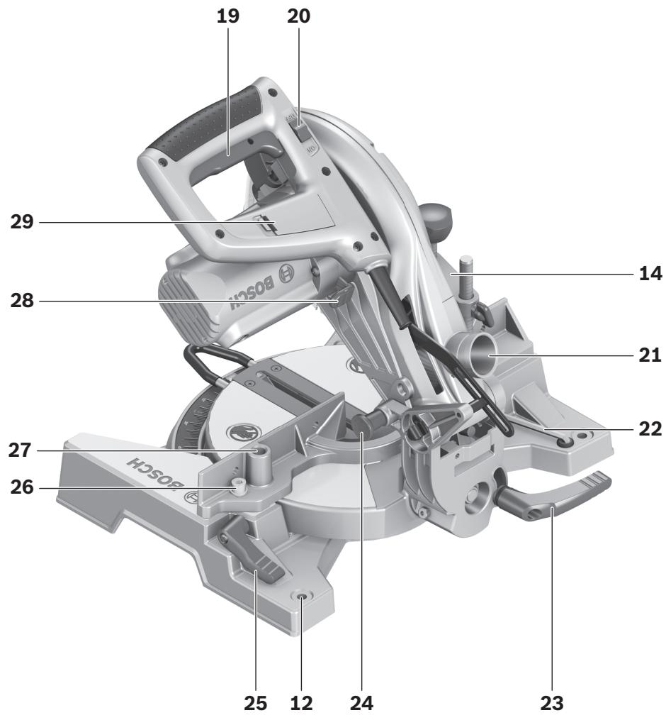
The numbering of the components shown refers to the representation of the power tool on the graphic pages.
1 Handle 2 Laser warning label 3 Lever for releasing the tool arm 4 Blade guard 5 Retracting blade guard 6 Fence 7 Insert plates 8 Screws for insert plate 9 Handle for turning the saw table 10 Scale for mitre angle (horizontal) 11 Saw table 12 Mounting holes 13 Recessed grips 14 Quick-action clamp 15 Scale for bevel angle (vertical) 16 Roller 17 Saw blade 18 Dust bag 19 On/Off switch 20 Laser switch (for marking of cutting line) 21 Sawdust ejector 22 Allen key (size 6 mm)
23 Clamping lever for various bevel angles (vertical) 24 Transport safety-lock 25 Clamping lever for any mitre angle 26 Allen screws (6 mm) of the fence 27 Holes for quick-action clamp 28 Spindle lock 29 Battery compartment 30 Allen screw (size 6 mm) for mounting of saw blade 31 Clamping flange 32 Interior clamping flange 33 Wing bolt 34 Threaded rod 35 Angle indicator (horizontal) 36 Angle indicator (vertical)
Accessories shown or described are not part of the standard delivery scope of the product. A complete overview of accessories can be found in our accessories program.
Technical Data
| Chop and Mitre Saw | PCM 7 | |
| Article number | 3 603 M01 2.. | |
| Rated power input | W | 1100 |
| Rated voltage | V | 230 |
| Frequency | Hz | 50/60 |
| No-load speed | min-1 | 4800 |
| Laser type | 650 nm, < 1 mW | |
| Laser class | 2 | |
| Weight according to EPTA-Procedure 01/2003 | kg | 8.0 |
| Protection class | ☐/II | |
| Permissible workpiece dimensions (maximal/minimal) see page 30. | ||
| The values given are valid for nominal voltages [U] of 230 V. For lower voltage and models for specific countries, these values can vary. | ||
| Please observe the article number on the type plate of your machine. The trade names of the individual machines may vary. | ||
Dimension of suitable saw blades
| Saw blade diameter | mm | 190 |
| Blade thickness | mm | 1.4–2.5 |
| Mounting hole diameter | mm | 30 |
Noise/Vibration Information
Measured values determined according to EN 61029.
Typically the A-weighted noise levels of the product are: Sound pressure level 93 dB(A); Sound power level 106 dB(A). Uncertainty K = 3 dB.
Wear hearing protection!
Declaration of Conformity
We declare under our sole responsibility that the product described under "Technical Data" is in conformity with the following standards or standardization documents: EN 61029, EN 60825-1 according to the provisions of the directives 2004/108/EC, 98/37/EC (until 28 Dec 2009), 2006/42/EC (from 29 Dec 2009).
Technical file at:
Robert Bosch GmbH, Dept. PT/ESC, D-70745 Leinfelden-Echterdingen
Dr. Egbert Schneider
Senior Vice President
Engineering
Dr. Eckerhard Strötgen
Head of Product
Certification
Robert Bosch GmbH, Power Tools Division
D-70745 Leinfelden-Echterdingen
Avoid unintentional starting of the machine. During assembly and for all work on the machine, the power plug must not be connected to the mains supply.
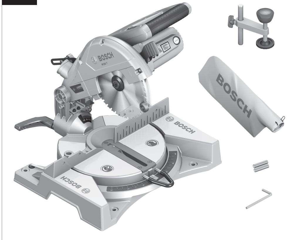
Delivery Scope

Please also observe the representation of the delivery scope at the beginning of the operating instructions.
Before starting the operation of the machine for the first time, check if all parts listed below have been supplied:
- Chop and mitre saw with mounted saw blade, dust bag 18
- Quick-action clamp 14
- Allen key 22
- Batteries (2x, size AAA, 1.5 V)
Note: Check the power tool for possible damage.
Before further use of the machine, check that all protective devices are fully functional. Any lightly damaged parts must be carefully checked to ensure flawless operation of the tool. All parts must be properly mounted and all conditions fulfilled that ensure faultless operation.
Damaged protective devices and parts must be immediately replaced by an authorised service centre.
Additionally required tools (not in delivery scope):
- Phillips screwdriver
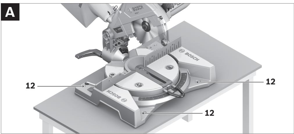
Mounting to a Working Surface
(see figure A)
To ensure safe handling, the machine must be mounted on a level and stable surface (e.g., workbench) prior to using. - Carefully remove all parts included in the delivery from their packaging. - Remove all packaging material from the machine and the accessories provided. - Fasten the power tool with suitable screw fasteners to the working surface. The holes 12 serve for this purpose.



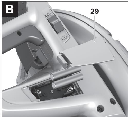
Inserting the Batteries
(see figure B)
- Open the battery compartment 29.
- Insert the batteries provided according to the specified polarity.
- Close the battery compartment.
Dust/Chip Extraction
Dusts from materials such as lead-containing coatings, some wood types, minerals and metal can be harmful to one's health. Touching or breathing-in the dusts can cause allergic reactions and/or lead to respiratory infections of the user or bystanders.
Certain dusts, such as oak or beech dust, are considered as carcinogenic, especially in connection with wood-treatment additives (chromate, wood preservative). Materials containing asbestos may only be worked by specialists.
- Use dust extraction whenever possible.
- Provide for good ventilation of the working place.
- It is recommended to wear a P2 filter-class respirator.
Observe the relevant regulations in your country for the materials to be worked.
The dust/chip extraction can be blocked by dust, chips or workpiece fragments.
- Switch the machine off and pull the mains plug from the socket outlet.
- Wait until the saw blade has come to a complete stop.
- Determine the cause of the blockage and correct it.
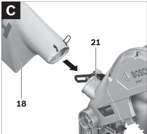
Integrated Dust Extraction
(see figure C)
- Mount the dust bag 18 onto the sawdust ejector 21.
During sawing, the dust bag must never come into contact with the movable machine parts.
Always empty the dust bag in good time.
External Dust Extraction
For dust extraction, a vacuum hose (size Ø36 mm) can also be connected to the dust ejector.
The vacuum cleaner must be suitable for the material being worked.
When vacuuming dry dust that is especially detrimental to health or carcinogenic, use a special vacuum cleaner.
Changing the Tool
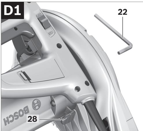
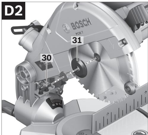
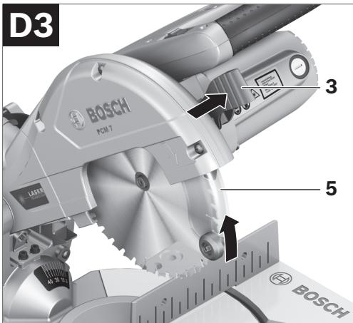
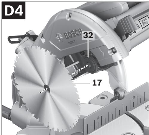
(see figures D1-D4)
Before any work on the machine itself, pull the mains plug. - When mounting the saw blade, wear protective gloves. Danger of injury when touching the saw blade.
Use only saw blades whose maximum permitted speed is higher than the no-load speed of the power tool.
Use only saw blades that correspond with the characteristic data given in these operation instructions and that are tested and marked in accordance with EN 847-1.
Removing the Saw Blade
- Bring the power tool into the working position.
- Turn the Allen screw 30 with the Allen key 22 provided while at the same time pressing the spindle lock 28 until it engages. Hold the spindle lock 28 pressed and unscrew the Allen screw 30 in clockwise direction (left-hand thread!).
- Remove the clamping flange 31.
- Press lever 3 and swing back the retracting blade guard 5 to the stop. Hold the retracting blade guard in this position and remove the saw blade 17.
- Slowly guide the retracting blade guard downward again.
Mounting the Saw Blade
If required, clean all parts to be mounted prior to assembly.
- Press lever 3, swing back the retracting blade guard 5 to the stop and hold it in this position.
- Place the new saw blade onto the interior clamping flange 32.
- When mounting the saw blade, pay attention that the cutting direction of the teeth (arrow direction on the saw blade) corresponds with the direction of the arrow on the blade guard!
- Slowly guide the retracting blade guard downward again.
- Place on the clamping flange 31 and the Allen screw 30. Press the spindle lock 28 until it engages and tighten the Allen screw turning in anticlockwise direction.
Operation
Before any work on the machine itself, pull the mains plug.
Transport Safety
(see figure E)
The transport safety-lock 24 enables easier handling of the machine when transporting to various working locations.
Releasing the Machine (Working Position)
- Push the tool arm by the handle 1 down a little in order to relieve the transport safety-lock 24. Pull the transport safety-lock 24 completely outward.
- Guide the tool arm slowly upward.
Securing the Machine (Transport Position)
- Tighten clamping lever 25 to lock the saw table 11.
- Press lever 3 and at the same time, swing the tool arm by handle 1 toward the rear until the transport safety-lock 24 can be pushed completely inward.
The tool arm is now securely locked for transport.
Clamping the Workpiece
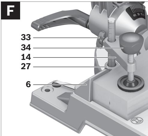
(see figure F)
To ensure optimum working safety, the workpiece must always be firmly clamped.
Do not saw workpieces that are too small to clamp.
- Press the workpiece firmly against the fence 6.
- Insert the quick-action clamp 14 provided into one of the holes 27 intended for it.
- Loosen the wing bolt 33 and adapt the quick-action clamp to the workpiece. Tighten the wing bolt again.
- Firmly clamp the workpiece by turning the threaded rod 34 in clockwise direction.
Loosening the Workpiece
- To release the quick-action clamp, turn the threaded rod 34 in anticlockwise direction.
Adjusting the Cutting Angle
- When adjusting the cutting angle, never actuate the On/Off switch 19. Danger of injury if the machine should accidentally start. Before sawing, always tighten the clamping lever 25. Otherwise the saw blade could become jammed in the workpiece.
Adjusting Horizontal Mitre Angles
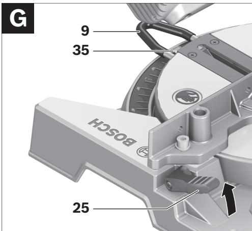
(see figure G)
The horizontal mitre angle can be set in the range from 46° (left side) to 46° (right side).
- Release clamping lever 25, if tightened. This allows the saw table to move freely.
- Turn the saw table 11 left or right by handle 9 until the angle indicator 35 indicates the desired mitre angle.
- Tighten clamping lever 25 again.
For quick and precise setting of often used mitre angles, the saw table 11 engages at the detents of the following standard angles:
-45° / -30° / -22.5° / -15° / 0° / 15° / 22.5° / 30° / 45°
Adjusting Vertical Bevel Angles
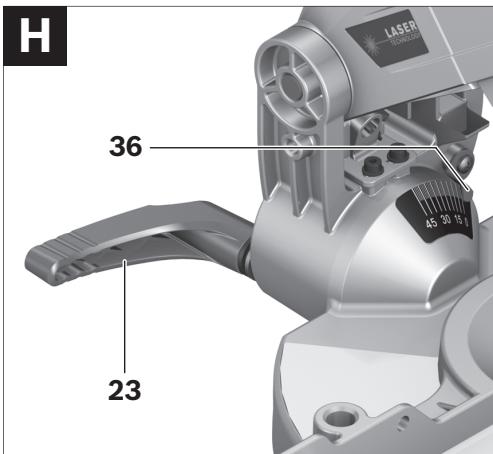
(see figure H)
The vertical bevel angle can be set in the range from 0° to 45°.
- Loosen the clamping lever 23.
- Tilt the tool arm by the handle 1 until the angle indicator 36 indicates the desired bevel angle. Hold the tool arm in this position and retighten the clamping handle 23.
For quick and precise setting of the standard angles 0° and 45°, end stops are provided on the housing.
- Loosen the clamping lever 23.
- For this, tilt the tool arm by the handle 1 to the stop toward the right (0°) or to the stop toward the left (45°).
- Retighten the clamping lever 23 again.
Starting Operation
Switching On
- To start the machine, press the On/Off switch 19 and keep it pressed.
Note: For safety reasons, the On/Off switch 19 cannot be locked; it must remain pressed during the entire operation.
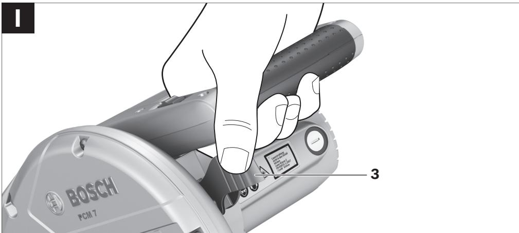
The tool arm can only be guided downward when pressing lever 3.
- For sawing, you must additionally press lever 3 in addition to actuating the On/Off switch. (see figure 1)
Switching Off
- To switch off the machine, release the On/Off switch 19.
Working Advice
General Sawing Instructions
For all cuts, it must first be ensured that the saw blade at no time can come in contact with the fence, screw clamps or other machine parts. Remove possibly mounted auxiliary stops or adjust them accordingly.
Protect the saw blade against impact and shock. Do not subject the saw blade to lateral pressure.
Do not saw warped/bent workpieces. The workpiece must always have a straight edge to face against the fence.
Long workpieces must be underlaid or supported at their free end.
Marking the Cutting Line
(see figure J)
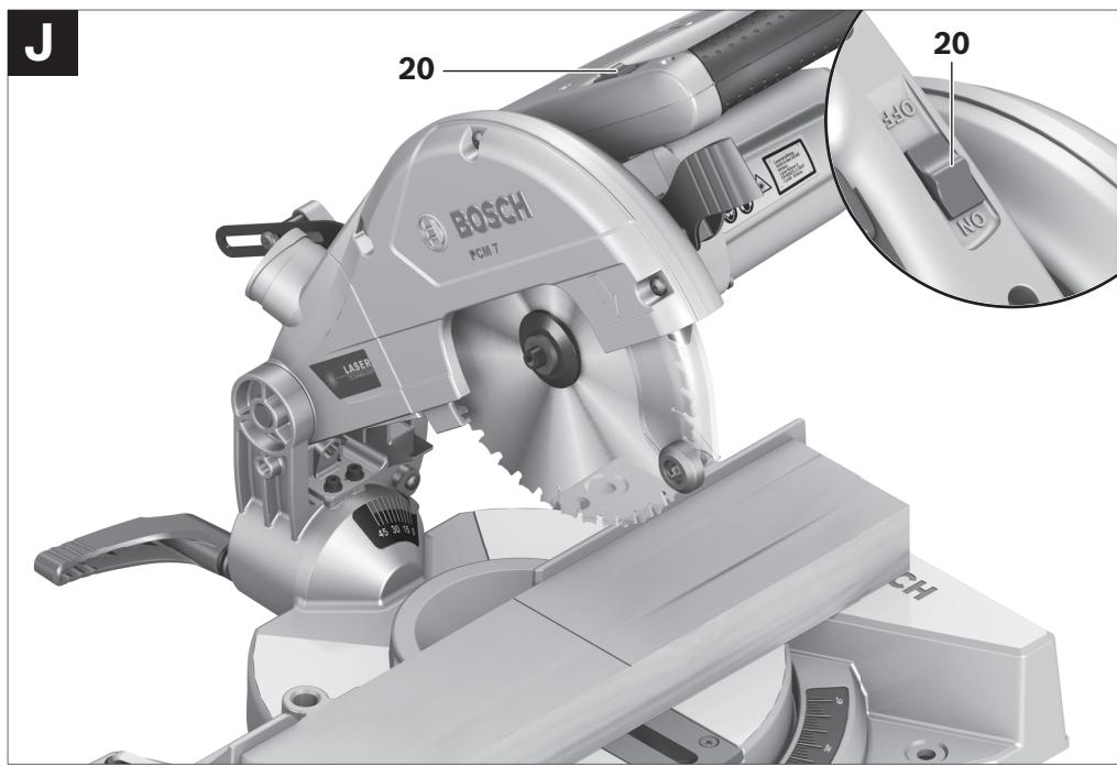
A laser beam indicates the cutting line of the saw blade. This allows for exact positioning of the workpiece for sawing, without having to open the retracting blade guard.
- For this, switch the laser beam on with the switch 20.
- Align the cutting mark on your workpiece with reference to the right-hand edge of the laser line.
Hand Positioning
(see figure K)
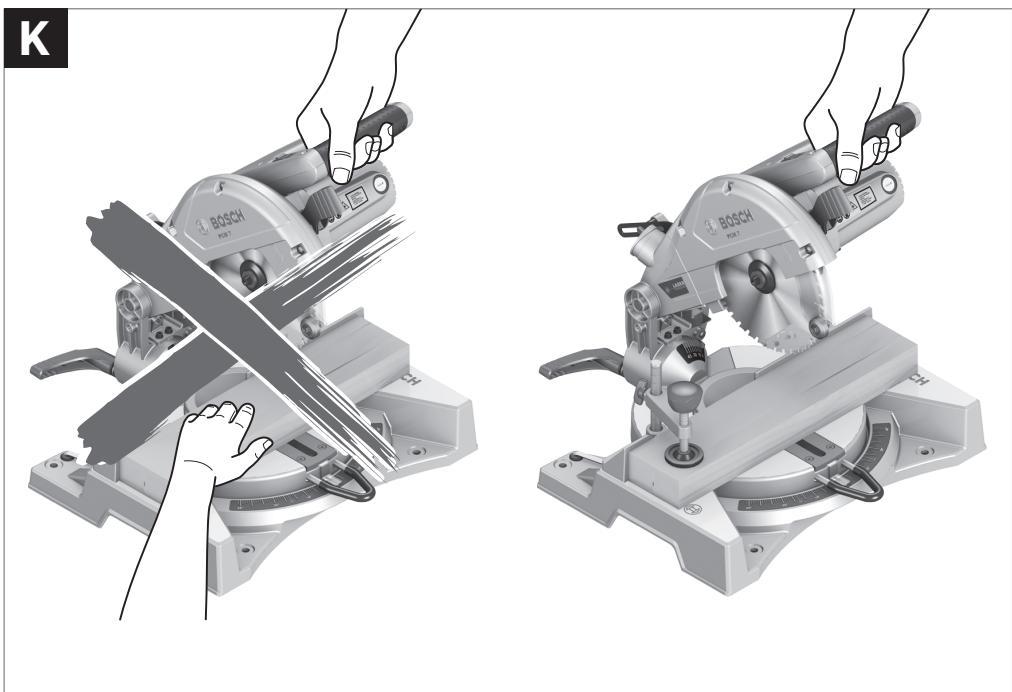
Keep hands, fingers and arms away from the rotating saw blade.
Do not cross your arms when operating the tool arm.
Permissible Workpiece Dimensions
Maximal workpiece sizes:
| Mitre/Bevel Angle | Height x Width | |
| Horizontal | Vertical | |
| 0° | 0° | 50 x 110 mm |
| 45° | 0° | 37 x 110 mm |
| 0° | 45° | 50 x 76 mm |
| 45° | 45° | 37 x 76 mm |
Minimal workpiece sizes
(= all workpieces that can be clamped left or right from the saw blade with the supplied quick-action clamp 14):
100 × 40 mm (length × width)
Cutting Off
- Firmly clamp the workpiece as appropriate for its dimensions.
- Adjust the requested horizontal and/or vertical metre/bevel angle.
- Switch on the machine.
- Press lever 3 and slowly guide the tool arm downward by handle 1.
- Saw through the workpiece applying uniform feed.
- Switch off the machine and wait until the saw blade has come to a complete stop.
- Guide the tool arm slowly upward.
Replacing the Insert Plate
The red insert plate 7 can become worn after long use of the power tool.
Replace defective insert plates.
Bring the power tool into the working position. - Unscrew screws 8 using a Phillips screwdriver and remove the old insert plate. - Insert the new insert plate and screw all screws 8 in again.
Sawing Profile Strips
Profile strips/mouldings can be sawn in two different ways:
- Placed against the fence
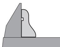
Lying flat on the saw table
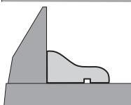
Always make trial cuts with the mitre angle setting first on scrap wood.
Transport
Bring the machine into the transport position. - For lifting or transporting, hold the power tool by the recessed grips 13 on the side of the saw table 11.
- When transporting the power tool, use only the transport devices and never use the protective devices.
Maintenance and Service
Maintenance and Cleaning
Before any work on the machine itself, pull the mains plug.
If the machine should fail despite the care taken in manufacturing and testing procedures, repair should be carried out by an after-sales service centre for Bosch power tools.
In all correspondence and spare parts order, please always include the 10-digit article number given on the type plate of the machine.
Cleaning
For safe and proper working, always keep the power tool and its ventilation slots clean.
The retracting blade guard must always be able to move freely and retract automatically. Therefore, always keep the area around the retracting blade guard clean.
Remove dust and chips after each working procedure by blowing out with compressed air or with a brush.
Clean the roller 16 regularly.



32 | English
Accessories
Saw blades for wood and plate materials, panels and strips/mouldings
Saw blade 190 × 30 mm , 40 teeth. 2609256821
Saw blade 190 × 30 mm , 12 teeth. 2609 256 868
Saw blade 190 × 30 mm , 24 teeth. 2608640615
Saw blade 190 × 30 mm , 60 teeth. 2608641188
After-sales Service and Customer Assistance
Our after-sales service responds to your questions concerning maintenance and repair of your product as well as spare parts. Exploded views and information on spare parts can also be found under:
www.bosch-pt.com
Our customer consultants answer your questions concerning best buy, application and adjustment of products and accessories.
Great Britain
Robert Bosch Ltd. (B.S.C.)
P.O.Box 98
Broadwater Park
North Orbital Road
Denham
Uxbridge
UB 95HJ
Tel. Service: +44 (0844) 736 0109
Fax: +44 (0844) 736 0146
Australia, New Zealand and Pacific Islands
Robert Bosch Australia Pty. Ltd.
Power Tools
Locked Bag 66
Clayton South VIC 3169
Customer Contact Center
Inside Australia:
Phone: +61 (01300) 307 044
Fax: +61 (01300) 307 045
Inside New Zealand:
Phone: +64 (0800) 543 353
Fax: +64 (0800) 428 570
Outside AU and NZ:
Phone: +61 (03) 9541 5555
www.bosch.com.au
Disposal
The machine, accessories and packaging should be sorted for environmental-friendly recycling.
The plastic components are labelled for categorized recycling.
Only for EC countries:
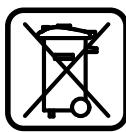
Do not dispose of power tools into household waste!
According the European Guideline 2002/96/EC for Waste Electrical and Electronic Equipment and its implementation into national
right, power tools that are no longer usable must be collected separately and disposed of in an environmentally correct manner.
Subject to change without notice.
Robert Bosch GmbH, Dept. PT/ESC,
D-70745 Leinfelden-Echterdingen
Dr. Egbert Schneider Senior Vice President Engineering
Dr. Eckerhard Strötgen Head of Product
Certification

Robert Bosch GmbH, Power Tools Division D-70745 Leinfelden-Echterdingen Leinfelden, 25.03.2009
Montage
Robert Bosch (France) S.A.S.
Dr. Egbert Schneider Senior Vice President Engineering
Dr. Eckerhard Strötgen Head of Product Certification
ppa. Maee i.v. Nooey
Robert Bosch GmbH, Power Tools Division D-70745 Leinfelden-Echterdingen Leinfelden, 25.03.2009
Montaje
Dr. Egbert Schneider Senior Vice President Engineering
Dr. Eckerhard Strötgen Head of Product Certification
ppa. Maee i.v. Nooey
Robert Bosch GmbH, Power Tools Division D-70745 Leinfelden-Echterdingen Leinfelden, 25.03.2009
Montagem
Dr. Egbert Schneider Senior Vice President Engineering
Dr. Eckerhard Strötgen Head of Product Certification
i.v. lojcu
Robert Bosch GmbH, Power Tools Division D-70745 Leinfelden-Echterdingen Leinfelden, 25.03.2009
78 | Italian
Assembly
Dr. Egbert Schneider Senior Vice President Engineering
Dr. Eckerhard Strötgen Head of Product Certification
Dr. Egbert Schneider Senior Vice President Engineering
Dr. Eckerhard Strötgen Head of Product Certification
Bosch Service Center
Telegrafvej 3
2750 Ballerup
Tel. Service Center: +45 (4489) 8855
Fax: +45 (4489) 87 55
E-Mail: vaerktoej@dk.bosch.com
Disposal
Dr. Egbert Schneider Senior Vice President Engineering
Dr. Eckerhard Strötgen Head of Product Certification
Robert Bosch GmbH, Power Tools Division D-70745 Leinfelden-Echterdingen Leinfelden, 25.03.2009
Assembly
Bosch Service Center
Telegrafvej 3
2750 Ballerup
Denmark
Tel.: +46 (020) 41 44 55
Fax: +46 (011) 187691
Disposal
Only for EU countries:
Dr. Egbert Schneider Senior Vice President Engineering
Dr. Eckerhard Strötgen Head of Product
Certification
Robert Bosch GmbH, Power Tools Division D-70745 Leinfelden-Echterdingen Leinfelden, 25.03.2009
Assembly
Dr. Egbert Schneider Senior Vice President Engineering
Dr. Eckerhard Ströttgen Head of Product Certification

Robert Bosch GmbH, Power Tools Division D-70745 Leinfelden-Echterdingen Leinfelden, 25.03.2009
Assembly
Dr. Egbert Schneider Senior Vice President Engineering
Dr. Eckerhard Strötgen Head of Product Certification
Robert Bosch GmbH, Power Tools Division D-70745 Leinfelden-Echterdingen Leinfelden, 25.03.2009
Sigma
When using the electric tool, always follow the safety instructions. According to the regulations, the electric tool must not be connected to the mains.
We reserve the right to make changes.
Safety Instructions
General Safety Instructions for Power Tools
Dr. Egbert Schneider Senior Vice President Engineering
Dr. Eckerhard Strötgen Head of Product Certification
Robert Bosch GmbH, Power Tools Division D-70745 Leinfelden-Echterdingen Leinfelden, 25.03.2009
Assembly
Minimum workpiece dimensions
(= all workpieces that can be secured to the right or left of the saw blade with the screw clamp 14 supplied with the tool):
100 × 40 mm (length x width)
Miter cutting
Bosch San. ve Tic. A.S.
Ahi Evran Cad. No:1 Kat:22
Polaris Plaza
80670 Maslak/Istanbul
Customer service: +90 (0212) 335 06 66
Customer service hotline: +90 (0212) 335 07 52
Disposal
Dr. Egbert Schneider Senior Vice President Engineering
Dr. Eckerhard Strötgen Head of Product Certification

Robert Bosch GmbH, Power Tools Division D-70745 Leinfelden-Echterdingen Leinfelden, 25.03.2009
Assembly
Robert Bosch Sp. z o.o.
Senior Vice President
Engineering
Dr. Eckerhard Strötgen
Head of Product
Certification
Robert Bosch GmbH, Power Tools Division
D-70745 Leinfelden-Echterdingen
Bosch Service Center PT
K Vapence 1621/16
692 01 Mikulov
Dr. Egbert Schneider Senior Vice President Engineering
Dr. Eckerhard Strötgen Head of Product Certification
ppa. /maee i.v. nuogcu
Robert Bosch GmbH, Power Tools Division D-70745 Leinfelden-Echterdingen Leinfelden, 25.03.2009
Assembly
Dr. Egbert Schneider Senior Vice President Engineering
Dr. Eckerhard Strötgen Head of Product Certification
ppa. /maee i.v. nuogcu
Robert Bosch GmbH, Power Tools Division
D-70745 Leinfelden-Echterdingen
Wear protective goggles.

Use hearing protection. Exposure to noise can cause hearing loss.

Do not point the laser beam at persons or animals, and do not look into the laser beam. This power tool produces laser radiation class 2 according to EN 60825-1. There is a risk of exposure to other persons.
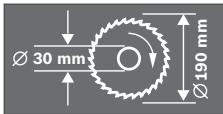
Observe the dimensions of the saw blade. The diameter of the hole must fit the tool spindle without play. Do not use reducers or adapters.

Dangerous area! Keep your hands and fingers away from this area as much as possible.

The transport guard 24 facilitates the transport of the power tool to different work sites.
- Transport guard 24 until stop: Activation of transport guard (transport position)
- Transport guard 24 until stop pulled out: Signal of transport guard (working position)

Symbol
Meaning
Only for EU countries:
Do not dispose of power tools in household waste! According to the European Directive 2002/96/EC on old electrical and electronic tools and devices and its implementation in national law, power tools that have reached the end of their service life must be collected separately and returned to an environmentally compatible recycling facility.
Description of functions

Read all safety instructions and instructions for the tool. Failure to follow the instructions and safety instructions
can result in electric shock, fire, and serious injuries.
Intended use
The power tool is intended for longitudinal and transverse straight cuts in wood, with the tool resting on a base. In this case, horizontal cutting angles from -46° to +46° and vertical cutting angles from 0° to 45° are possible.
The power of the power tool is designed for cutting solid and soft wood.
Illustrated components
The numbering of the components refers to the illustration on the graphics page.
1 Handle 2 Warning plate for laser radiation 3 Handle for loosening the tilt guard 4 Protective cover 5 Pendulum protective cover 6 Stop rail 7 Base plate 8 Screws for base plate 9 Handle for turning the saw table 10 Scale for cutting angle (horizontal)
11 CToA IINAbi 12 OTeBepCTnAa KpeIeHn 13 YrIy6leHnIaXbTa 14 Ctpy6uHa 15 Ⅲkaλa yγλa paçtnηλa (BéptnKaλbHOrO) 16 PoAnK cKOaBXeHnA 17ПиьньдИСК 18ПыевМшOK 19 BbIKAnOuAteAnb 20 BbikouateIb Ia3epa (o6o3hauehne IHHn paCIIIa) 21 BbI6poc OTnIOK 22 LTHTOBOI WecTnHpaHHbIKAIOU (6 MM) 23 3aKHMH a pyka dA IIO6O rIa HAKHOHa 24 TpaHCTIOPTbI INpeDOxpaHHTeB 25 3axmHoi pbuag IaIIO6o0 (roPnOHTaBHO) yra pacnna 26 BnHTb C BHyTpEHHM WecTnrgpaHHNKOM (6 MM) dA ynpHoi peKn 27 OTBepCTnAa Ctpy6uH 28 Φнксаторштпндeя 29 Otcek dAЯ 6aTapei 30 BnHT C BHyTpEHHM IeCTNrpAHHNKOM (6 MM) DЯ KpeTlAeHNA TINAbHOrO dNcKa 31Ппнхимнофlaheu 32 BnytpenHHn 3axmHNOI aHaNeu 33 BapaaKOBbI BNHT 34 BnHT Ctpy6uHbI 35 Yka3aTeIb yIa pacTIIa (rOpH3OHTaIbHorO) 36 Yka3aTeIb yIa pacTHnla (BepTKKaIbHorO)
The accessories shown or described are not included in the standard scope of delivery. You will find the complete range of accessories in our accessories program.
Technical data
Data on noise and vibration
Dr. Egbert Schneider Senior Vice President Engineering
Dr. Eckerhard Strötgen Head of Product Certification
ppa. Maee i.v. Nooey
Robert Bosch GmbH, Power Tools Division D-70745 Leinfelden-Echterdingen Leinfelden,25.03.2009
Assembly
Before any work on the power tool, pull the plug out of the socket. During mounting and all other work on the power tool, the plug must be disconnected from the power supply.
Scope of delivery

See information on the scope of delivery at the beginning of this operating manual.
Before first use of the power tool, check that all components listed below are present:
Cordless screwdriver with installed saw blade - Dust bag 18 - Clamping lever 14 - Hex key 22 - Batteries (2x, size AA, 1.5V)


Note: Check the power tool for possible damage.
Before using the power tool, always check the protective devices and components for minor damage and for proper function. Check the protective function, free movement, and condition of visible parts. All parts must be correctly installed and fulfill all conditions for safe operation.
Damaged protective devices and components must be repaired by a qualified specialist or replaced.
Tools additionally required for the delivery kit:
- Phillips screwdriver
Mounting on the work surface
(see fig. A)
To ensure reliable operation of the power tool, it must be installed on a flat, stable work surface (e.g., a workbench). - Carefully unpack all supplied parts. - Remove all packaging material from the power tool and supplied accessories. - Secure the power tool with suitable screws to the work surface. The holes 12 are provided for this purpose.
Battery installation
(see fig. B)
- Open the battery compartment 29. Insert the batteries from the delivery kit according to the indicated polarity.
- Close the battery compartment.
Dust and chip extraction
Dust from materials such as paint containing lead, some types of wood, minerals, and metal can be harmful to health. Contact with dust and inhaling dust can cause allergic reactions and/or respiratory diseases of the operator or nearby persons.
Certain types of dust, such as oak and beech dust, are considered carcinogenic, especially in combination with additives for wood treatment (chromate, wood preservative). Material containing asbestos may only be processed by specialists.
- Always extract chips.
- Clean for good ventilation.
- It is recommended to use a respirator with a P2 filter class.
Observe the regulations in force in your country for the materials being processed.
Dust/chip extraction may be impossible due to dust, chips, and also broken workpiece fragments.
Turn off the power tool and pull the plug out of the socket. Wait until the dust extraction has completely stopped. - Find the cause of the blockage and eliminate it.
Integrated dust extraction system
(see Fig. C)
Attach the extraction hose 18 to the chip ejection port 21.
During operation, the hose must not come into contact with moving parts of the machine.
Empty the dust bag in a timely manner.
External dust extraction system
The chip ejection port can be connected to a vacuum cleaner hose (36 mm).
The vacuum cleaner must be suitable for the material being processed.
Use special extraction devices for materials that are hazardous to health - carcinogens or dry dust.
Replacing the tool (see Fig. D1-D4)
Disconnect the power cord plug from the mains socket before performing maintenance or adjustment work on the power tool. When installing the grinding disc, wear protective gloves. Contact with the grinding disc can cause injury.
Use only grinding discs with a maximum permissible speed not less than the no-load speed of your power tool.
Use only grinding discs whose parameters are specified in this manual, which have been tested according to EN 847-1 and bear the corresponding marking.
Mounting the grinding disc
- Place the power tool in the working position. - Turn the spindle lock until it engages. Press the spindle lock and simultaneously turn the screw in the direction of the arrow (left-hand thread!). - Remove the clamping flange. Press the lever and fold the protective guard back until it stops. - Hold the protective guard in this position and remove the grinding disc. - Slowly fold the protective guard back.
Mounting the grinding disc
Do not touch the tool during operation.
Permissible workpiece dimensions
Maximum workpiece dimensions:
| Угол | Велиотахшерпа | |
| Горизон-Талове ПOTOLOЖЕНИ | Верн-Калове ПOTOLOЖЕНИ | |
| 0° | 0° | 50 x 110 MM |
| 45° | 0° | 37 x 110 MM |
| 0° | 45° | 50 x 76 MM |
| 45° | 45° | 37 x 76 MM |
Minimum workpiece dimensions:
(= all workpieces that can be clamped on the left or right of the disc using the supplied pipe wrench 14):
The Bosch consulting team will be happy to answer your questions about the application and adjustment of products and accessories.
Russia
Robert Bosch LLC
Service center for power tool maintenance
ul. Akademika Koroleva 13, stroenie 5, 129515, Moscow
Tel.: +7 (495) 9358806
Fax: +7 (495) 9358807
E-Mail: rbru_rt_asa_mk@ru.bosch.com
OOO «Robert Bosch»
Service center for power tools
ul. Tsvetochnaya, 41
198095, Saint Petersburg
Tel.: +7 (812) 4499711
Fax: +7 (812) 4499711
E-Mail: rbru_ct_asa_spb@ru.bosch.com
OOO «Robert Bosch»
Service center for power tools
Gorsky Microdistrict, 53
630032, Novosibirsk
Tel.: +7 (383) 3599440
Fax: +7 (383) 3599465
E-Mail: rbru_rt_asa_nob@ru.bosch.com
OOO «Robert Bosch»
Service center for power tools
ul. Fontannykh brigad, 14
620017, Yekaterinburg
Tel.: +7 (343) 3658674
Tel.: +7 (343) 3787756
Fax: +7 (343) 3787928
Belarus
PT «Robert Bosch» OOO
220035, Minsk
ul. Timiryazeva, 65A-020
Tel.: +375 (17) 2 54 78 71
Tel.: +375 (17) 2 54 79 15
Tel.: +375 (17) 2 54 79 16
Fax: +375 (17) 254 78 75
E-Mail: bsc@by.bosch.com
YTHAN3aun
Used power tools, accessories and packaging should be disposed of at an ecological recycling facility.
For sorting of waste for recycling of synthetic materials, they are correspondingly marked.
Only for EC countries:
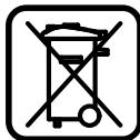
Do not dispose of power tools into household waste! According to the European Directive 2002/96/EC on old electrical and electronic equipment and instruments, and
its implementation in national law, power tools that have reached the end of their service life must be collected separately and disposed of at an ecological recycling facility.
Changes may be made.

ME77
Safety instructions
General warnings for power tools
4 WARNINGS
Important safety instructions.
Failure to follow the safety instructions may result in electric shock, fire, and/or serious injury.
Keep all safety instructions for future reference.
The term "power tool" in the safety instructions refers to your mains-operated (corded) power tool or battery-operated (cordless) power tool.
Illustrated components
The numbering of the illustrated components refers to the illustration of the power tool on the pages with figures.
1 Handle 2 Trigger switch 3 Lock-off button for the on/off switch 4 Protective guard 5 Pendulum guard 6 Control knob 7 Insert tool 8 Screw for insert tool 9 Handle for turning the oscillating table
10 Hex key (6 mm) 11 Spindle 12 Mounting holes 13 Rear handle 14 Clamp 15 Scale for cutting angle (vertical) 16 Roller 17 Base plate 18 Dust bag 19 Chip deflector 20 Chip deflector for laser (for cutting line) 21 On/off switch 22 Hex key (6 mm) 23 Locking handle for setting the cutting angle (vertical) 24 Transport lock 25 Locking lever for setting the cutting angle (horizontal) 26 Screw with hex key (6 mm) for the auxiliary handle 27 Clamp for workpiece 28 Fixing screw 29 Battery compartment
30 Screw with hex key (6 mm) for securing the base plate 31 Locking flange 32 Inner locking flange 33 Wing bolt 34 Spindle with thread 35 Angle indicator (horizontal) 36 Angle indicator (vertical)
The illustrated or described accessories are not included in the standard delivery. The complete range of accessories can be found in our accessories program.
Technical data
Technical documents at: Robert Bosch GmbH, Dept. PT/ESC, D-70745 Leinfelden-Echterdingen
Dr. Egbert Schneider Dr. Eckerhard Strötgen Senior Vice President Head of Product Engineering Certification

Robert Bosch GmbH, Power Tools Division D-70745 Leinfelden-Echterdingen Leinfelden, 25.03.2009
Mounting
YHnKaIte HeHaBMnCHOrO 3aNcye eKToPpHaAу. IIa cac MoHTaxHnx Ta iHux p6iT 3 eKToPpHaAOM wTeNCaB He ToBnHe 3hAxODHTncB P03eTu.
06cgr nocTabKn

AIB.06cTIOCTaBKn,IO 3a3haueHnHaIOuATky IHCTpyKuii 3ekCnIyatauii.
П配电Д рочатКOM рбOTи 3 eLEKТрОПРИАДОМ п配电ВірTE HaBbHcTb BCIX HnKcYeBka3aHnx ДeTaБeI:
TopuOBAaBHO-BycOpi3Ha TINKa 3 MOHTOBaHIM TINLAbHIM DnCKOM - Tnlo36ipHmMiueyok 18 - ctpy6uHa 14 KIAOu-WeecTHrpaHHNK 22 -Багарейки(2wt,po3mipAAA,1,5B)
Bka3iBk: Ipebeipte eIeKtpoPnlaHa Ha IpeMet MOXANBHX TPOWKOKeHb. IpeD IPOODBKeHNM EKCIIyataii eIeKTPoPnlaApy peTeIbHO IpeBeipTe 3axNCHi IpiCTpoT a 3JeRKa IIOWKoDKeHi DeTaIHa IpeMet 6e3OraHHOI pObToN i BiIOBIAHOcti ix Ipi3NaueHHIO. IpeBeipTe, uN 6e3OraHNO IpaIOuTOb pyxomi DeTAli, uN He 3aCtPnIOb BOHn i Hn Hemae IIOWKoDKeHNx DeTAlE. DnA 3a6e3NeueHHy 6e3OraHHOI pObToN BcI DeTAli MaIObT bYtN IIpnBHO MONTOBAHmN i BiIOBIAATN BCIM BmMOrAM. IproWKoDKeHi 3axNCHI IpiCTpoI i DeTAli Tpe6a HaLexHmM uHOM BiPeMOHTyBaTH n A60 IomInrHn y 3apeCTPOBaHI CteuaIIaOBaHm MaICTepHi.
Ihctpymentn, TOTpi6Hi DOaTkoBO Do 06cary TOCTaBKn:
-xpecToIooi6Ha BnKpyTka
Mоntханpo6oui nOBepxhi
(△H.B.MaA.A)
3a6e3eunTH 6e3eunHyMOBN ApyyBaHHn, TpeAekTnAyatauie eEeKTPoPnHaTpe6a MOHTyBaTH Ha pIBnH Ta cTa6iBnI IOBepxHi (HaTp., Ha BepCTaky). - O6epexHo BnMItb BcI deTani 3 yTnakOBKn. 3HIMITb 3 eIeKTPoPnPaLy i 3 PpNlAaBBA BcO yIaKOBky. 3a DOnOMoHOI pNdaTHnx rBnHTiB 3akpiitb eEeKToPoiPiAA Ha po6oui IOBepxHi. AAn zuBoI OpeAbaehi OTbOpN 12.
BcTpomHnHa 6aTapeHok
(△H.B.MaA.B)
BiiakpnTe cekciio 4aTaapeiok 29. BCTpOMiTb OdoHibiTaapeKKn BiIOBIAHO OHaIITpaBAeHOCTI POIAOCIB. 3akpiTe cekiuO 6aTapeHok.
BiAcMOKTyBaHHaTHy/THpcn/CTpyxKKn
Plastic materials, paints, varnishes, coatings, containing lead, wood preservatives, minerals and metals, can be hazardous to health. Touching or inhaling them may cause allergic reactions and/or respiratory diseases.
Dense wood, plywood, oak or beech wood, are considered the best, especially in combination with wood protection products (stains, wood preservatives). Materials containing asbestos may only be processed by specialists.
Remove the tool. Connect the dust extraction system. It is recommended to wear a respirator mask with P2 filter.
Make sure that the materials to be processed are safe for your health.
The dust extraction device may become clogged with dust, shavings, or workpiece debris.
Unplug the power cord from the outlet. Note that the saw blade is still hot. Wait for it to cool down and then remove it.
Dust extraction system
(Fig. A, pos. C)
Connect the dust extraction hose (21) to the dust extraction port (18).
The dust extraction bag must not be in contact with moving parts of the saw.
Empty the dust extraction bag regularly.
External dust extraction
The dust extraction device can be connected to the dust extraction port (Ø36mm).
The dust extraction device must be suitable for the material being processed.
For dust extraction, it is recommended to use a special dust extraction device for dry or wet dust.
(see fig. D1-D4)
Before any work with the electric tool, pull the plug out of the socket. When mounting the saw blade, be sure to wear protective gloves.
Touching the saw blade involves a risk of injury.
Use only saw blades whose maximum permissible speed is higher than the no-load speed of the electric tool.
Use only saw blades that meet the characteristics specified in the instructions, are tested according to EN 847-1, and have the appropriate marking.


Removing the saw blade
Place the electric tool in the working position. Using the hex key 22, turn the screw with the internal hexagon 30 counterclockwise to release the spindle lock 28, so that it engages. Hold the spindle lock 28 pressed and turn the screw 30 in the direction of the arrow (two turns!). Remove the clamping flange 31. Press the spindle lock 28 and pull the pendulum guard 5 upward or backward. Hold the pendulum guard in this position and remove the saw blade 17. Completely lower the pendulum guard again.
Mounting the saw blade
If necessary, clean all parts to be mounted before mounting.
Press the spindle lock 28, pull the pendulum guard 5 upward or backward and hold it in this position. Place the new saw blade on the inner clamping flange 32.
Adjusting the vertical miter angle
(see fig. H)
The vertical miter angle can be set in the range from 0° to 45°.
Loosen the clamping handle 23. Grasp the handle 1 and tilt the tool head until the angle indicator 36 shows the desired miter angle. Hold the tool head in this position and retighten the clamping handle 23.
AII WbHAKORIOI TOUHOROBCTAHOBaEHNAHTAHAPTHNX KytIB PO3NIAOBAHHa 0° Ta 45° HaKopnyi pepe6buehi KIncebi ynpn.
BiπyctiTb 3aTHCKHy pyKoTky 23. -ДЯцboro,ВЗЯВИисьзу pyKoRTky1,нхиNTь кронштейн робочо iHCTpyMeHTadoу npopyпраBOpyu (0°) a6o doу npopyʌibopyu (45°) - 3HOby 3aTArHITb 3aTHcKHy pyKOaTky 23.
Touatok po60tn
BMKKaHHa
Ioo6 yBIMKHyTH IpiHnAa,HaTNCiTb Ha BmHKa4 19 Ta TpImaTe NOrO HATNCHyTM.
Bka3iBka: 3 MIPkyBaHb Texhikn 6e3neKn BmNkau 19 He MoxHa 3aΦiKcByaTn, Ioro Tpe6a TpMaTH HaTHCHyTHM IPOTRAOM BCei po6oTH.
KpoHtTeH po6OOro IHCTpyMeHTa MoXHa OYCTHTn DOHN3y, NHe HAtCHyBn Ha BaXiA 3.
- p03TNIOBAAH B IOBHHI OaTkoBO DO IINBEeEHRAIHO BVIMKauHaTHCHYb BaxiAb 3. (NVB.MaI.1)
BmmkaHn
- Ⅲo6 BmKHyTh eIeKtpOpiPnlaA, BiIpyctiTb BmHKa4 19.


Bka3iBkn 0oDo po6Otn
3araAblhi BkazBkn 10do pO3nIOBAHH
Pn Bcix p06Tox 3 po3nIAOBaHH nctouatky Bam tpe6a nepekoHaTnc, zo nIbHn DnCK Hi Pn kNx yMOBaX He MOKe TOpKaTHCn yTOpHOi uHH, cTpy6uHH nn iHux DeTaAeN PnHaAdy. Pn6epitb MOKAnBO MOnTOBahi DoaATKObi yTOnp a6o BiIOBIDHM YHOM PnITacyTe ix.
3axnauTe pHAnbHn dNcK bIyapIB i IpoTobxIB. He hATNCkyTe Ha pHAnbHn dNcK 36Oky.
He 6p6nTe BnKPNBLeHi 3aTObKn. 3aTObKa 3aBXKn IOBnHa MaTH pIBHn Kpa DAn PnKkAeHHo yIOPHOI uHHN.
Pn o6p6u IOBx DeaIe IiX BHN KHeu Tpe6a 0-He6yDb IaKlaCTn a6o IIaTepTu Horo.
T03haueHHAiiHPO3THIAOBAHHA
(ANB.MaJ.J)
Промиьламера погаае liinpo3пншовнипльним днckom.Завдки цbomy 3arotobky moЖHaToCHo pO3TaWOBByBaNrДЯ рОЗпншовни,прицbomy He NotpioHo BiIDKPNBaTN MaTTHNKOBy 3axnchy Kpnshky.
- YbIMKhitbIa3ep 3a DOnTOMOHO BmHKaay20. BnpiBnIte BaUy IIO3NaCy Ha o6pO6IoBaIbHiI AeTaI IIO IpaBOMy KpaI Oa3epHOi AiHii.
TIOBOXeHH
(ANB.MaI.K)
He πiǎctaBλrηTe pykni pIaIbci πiδ πIIaIbHn IaNCK, 0o o6eptac.
He cxpeuTy peKn ppek KpOHTeHOM.
Donycthmi po3mipn 3arotobkn
MaKcMaIbHI 3aROTOBKn:
| Кут розиювannah Горион- Талбни | Верты- Калбни | Висota x ШирINA |
| 0° | 0° | 50 x 110 MM |
| 45° | 0° | 37 x 110 MM |
| 0° | 45° | 50 x 76 MM |
| 45° | 45° | 37 x 76 MM |
Mihimaibhi 3aROTOBKn:
(=BCi3aROTOBKN,AkiMOKHa3aTHCKyBaTH AIbOpy TaIpaBOpuy BiDIIHAAHBOHO DNCKa 3a DOITOMORIO DOaHOI CTpy6uHN14): 100x40MM (doBXnHaX shpiHa)
TopoiobanH
- 3aTnchIb 06po6IoBaHy 3aRToBky BiTOBIAHOo II pO3mipIB. BctaHObITb Heo6xIDHn rOpH3OHTaIbHn Ta/a6o BepTnKaIbHn Kyt p03IIIOBaHH.
- YbIMKHiItb eAeKtpoPiuaA. HaTnCHiB BaxiIb 3 i, B3aBwHcB 3a pyKoTky 1,IOBIaHo ONTyCTiB KpOHwTeH pOboQOr o IHcTpymeHTa.
- P03ПИЛЮУТe 6Opo6HOBaHy 3aIOTOBky 3 piBHomipHOIO TIOdaueHO. BnMKnHt b eAeKtpoPiPnla i 3aueKaIte, TOKI HAAhN N DCK IOBHICTIO He 3yINHTbCra. I NobiNbHO iHimItb kpoHtTeH pOboOro ihcTpymeHa yropy.
3amiha BCTABHORO ⅢNTka
Texhiye 06cayrobyBaHHi ouHsEHnA
Ipea 6yab-RAKMMAHmYAAUcIMM3 eAeKTPoPpnaAOM BHTARHITb wTeTceA b 3 po3ETKn.
Kzho He3BaXaOuH Ha peTeIbHy TexHOIoIO BnroTOBLeHHN i IpeBepiPKn PpIaD BCE-TaKn Bnnde 3 Aady, Noro peMOHT Do3BOAeTbcra BkOHyBaTH NlSe B aBTopn3OBaHi cepBicHi MaICTepHI dA eEKeTPOPiPnlaIB Bosch.
PnBcIX 3aHTAHHIXI Pn3aMOBHeHHI 3aTnactnH,6yIb IacKa,06OB'3KOBO 3a3HaayTe10-3NaHmTOBapHmHOMep,IO 3NaXoHbCnHa 3aBOcBki Tabuui ci EeKTPoPiHaAdy.
OuHueHH
Дяяк hoi i 6e3neuhoi po6toN trmaite eIek-tpoPnlaiaD i BENTnlauiHi OTbOpN B uHCToti.
MaTnKOBn 3axnChn KoxyMae 3aBxDi BiaHo IepecyBaTHcI c amoCTiH0 3aKnBaTHcI.3iEi PrnHH 3aBXn TpMaJTe 3OHy HbKOLO MaTnKOBOrO 3axnCHOrO KoxyXa B uHCTOTi.
Ticra Koxhoi pobooi oepaui 3dyBaTe nai i ctpyKky CTncHEHm NOBITpAm a6o 3mitaIte ix uTOOKOIO.
Perylaepno Ipoounaai Te KOB3nH poAik 16.
PpHnAa
TnAaBhi DnCKN AAn DepeBa, nHT, nanei peok
ПИАльнДИСК 190x30MM, 40у6и .2609256821
Service Master and Customer Care
In the service master, you will receive answers to your questions regarding the repair and maintenance of your product.
You can find spare parts in the data and information at the address:
www.bosch-pt.com
Bosch consultants will be happy to help you with questions regarding the purchase, use, and supply of products and accessories.
Ukraine
Bosch Service Center for Power Tools
Krany St., 1, 02660, Kyiv-60
Tel.: +38 (044) 512 03 75
Tel.: +38 (044) 512 04 46
Tel.: +38 (044) 512 05 91
Fax: +38 (044) 512 04 46
E-Mail: service@bosch.com.ua
The addresses of the regional warranty service workshops are indicated in the warranty card.
Disposal
The machine, accessories and packaging should be sorted for environmental-friendly recycling.
Do not dispose of power tools into household waste!
Only for EC countries:
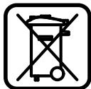
According to the European Directive 2002/96/EC for Waste Electrical and Electronic Equipment and its implementation in national law, power tools that are no longer usable must be collected separately and disposed of in an environmentally correct manner.
According to the European Directive 2002/96/EC for Waste Electrical and Electronic Equipment and its implementation in national law, power tools that are no longer usable must be collected separately and disposed of in an environmentally correct manner.
According to the European Directive 2002/96/EC for Waste Electrical and Electronic Equipment and its implementation in national law, power tools that are no longer usable must be collected separately and disposed of in an environmentally correct manner.
Subject to change without notice.
238 | Roman
Dr. Egbert Schneider Senior Vice President Engineering
Dr. Eckerhard Strötgen Head of Product Certification
ppa. Maee i.v. Nooey
Robert Bosch GmbH, Power Tools Division D-70745 Leinfelden-Echterdingen Leinfelden,25.03.2009
Mounting
Bosch Service Center
Str. Horia Macelariu Nr. 30-34, 013937 Bucuresti
Tel. Power tools service: +40 (021) 4 05 75 40
Fax: +40 (021) 405 7566
E-Mail: infoBSC@ro.bosch.com
Tel. Technical consultation: +40 (021) 4 05 75 39
Fax: +40 (021) 405 7566
E-Mail: infoBSC@ro.bosch.com
www.bosch-romania.ro
Disposal
Power tools, accessories, and packaging must be directed to an ecological recycling station.
The sound pressure level at the workplace can exceed 80 dB(A); sound power 106 dB(A). Uncertainty K=3dB.
Wear ear protection!
Declaration of Conformity
We declare under our sole responsibility that the product described under “Technical Data” complies with the relevant standards and normative documents: EN 61029, EN 60825-1 in accordance with the provisions of Directives 89/336/EEC, 98/37/EC (until 28.12.2009), 2006/42/EC (from 29.12.2009).
Technical file at: Robert Bosch GmbH, Dept. PT/ESC, D-70745 Leinfelden-Echterdingen
Dr. Egbert Schneider Senior Vice President Engineering
Dr. Eckerhard Strötgen Head of Product Certification
ppa.
i.v. Mojgcu
Robert Bosch GmbH, Power Tools Division D-70745 Leinfelden-Echterdingen Leinfelden, 25.03.2009
Assembly
Warning! Before any work on the power tool, pull the mains plug out of the socket. During assembly and whenever any work is performed on the power tool, the tool must be disconnected from the mains.
Scope of delivery

Carefully read the scope of delivery shown at the beginning of the operating instructions.
If any parts are missing or damaged, contact your dealer immediately.
Circular saw blade for cutting and slotting with mounting hole - Carbide-tipped saw blade 18 - Countersunk screw 14 - Hex key 22 (2x, size 4, 1.5 V)
Warning: Do not use the power tool if it is damaged.
Before using the power tool, you must carefully check that the replaceable parts are not damaged. Check that the surface parts are correctly attached and do not jam or have other damaged parts. Every part must be mounted correctly and must meet all conditions for safe operation.
Damaged replaceable parts must be repaired or replaced by a qualified technician authorized for power tool service.
Tools required for mounting:
- Phillips screwdriver
Mounting on the work surface
(See Fig. A)
To ensure safe operation of the power tool, before using it, you must mount it on a flat and stable work surface (e.g., workbench). Carefully remove all packaging material from the power tool and the accessories included in the kit. Fasten the power tool to the work surface using the screw connections provided. To do this, drill the holes (12).
Inserting the batteries
(See Fig. B)
- Open the cover of the battery compartment (29). Insert the batteries included in the kit, observing the polarity.
- Close the cover of the battery compartment.
Dust extraction system
Dusts generated during material processing, such as lead-containing paints, some types of wood, minerals, and metals, can be harmful to health. Contact with the skin or inhalation of such dusts can cause allergic reactions and/or respiratory diseases in the operator or persons nearby.
Certain dusts, e.g., from processing beech or oak, are considered carcinogenic, especially in combination with wood treatment additives (chromate, wood preservatives, etc.). Only allow asbestos-containing materials to be processed by appropriately qualified personnel.


Use a dust extraction system. - Ensure good ventilation of the work area. - It is recommended to wear a breathing mask with filter class P2.
Clean and safe working conditions are regulated by law. When processing the respective materials, follow the regulations.
The dust extraction may be blocked by dust, shavings, or debris from the workpiece.
- Disconnect the power tool from the power supply and remove the battery pack before making any adjustments. Wait until the accessory has come to a complete stop. - Open the clamping lever for the dust extraction.
Dust extraction system
(See Figure C)
Insert the dust extraction hose into the extraction outlet (21) for removing chips.
During operation, the dust extraction hose must not come into contact with the hot parts of the power tool.
Empty the dust extraction hose regularly.
Dust extraction system
At the end of the chip ejection outlet, you can connect a vacuum cleaner hose (Ø 36 mm).
The vacuum cleaner used must be suitable for working with the processed material.
If, during work, dust is generated that is particularly harmful to health or carcinogenic, use a special vacuum cleaner.
Changing the tool
(See Figure D1-D4)
Before performing any work on the power tool, disconnect the plug from the power supply. When mounting the circular saw blade, wear protective gloves. When changing the circular saw blade, there is a risk of injury.
N3TIO3BaIte cAmO pexeun DNCKOBe, YnraTo MaKcMaHNO DOITyCTMa CKOpOCT Ha BbPtHe e ITO-BvCoka OT CKOpOCTTa Ha BbPtHe Ha Ipaazeh XoHa Ba7HrEeKTPoHnCTpyMeHT.
ИзлбаитсамоцркуарнDNCKOBe,КоNTO CBOTBeTCTBaTHaПОСочЕНTeВTOBa pьКОвOДТВОз eKСПоАтuaиДaHHиСа ИПИТаHи ПО EN847-1иOBОЗhaЧeHи ПО CBOTBETHNЯHAчH.
DemoHTnpaHe Ha uPkyArypHnA dnck
-Пoctabete eAektpoHnCtpymeHaВ pa6OTHa ПОЗиця. 3aBbPTeBE BnHTa C rAba C BbTppeH 30C BKIoUeHINB OKOMIIeKTOBkATA 8cTOCTeHEN KIOU22 H eHOBpeMeHHo HaTNCHeTe 6yToHa 3a 6loKnpaHe Ha BaLa 28,doKaTO yCeTHe TpeuPaKBaHe. 3aApbXte 6yToHa 3a 6IoKnpaHe Ha BaIa 28 HATNCHa I pa3BnIe BnHTa 30 KaTO rOBbPTTe IIO IIOcOKa Ha YacOBHnKOBaT aCTpeIka (AraBa pe36a!!). - demoHTnpaIte 3actoToPRAuINaHHeu 31. HaTnCHeTe loCTa 3 n 3aBbptTe 7apHnnpOkaueHHIpeDIIa3eH KOxUx 5 do yIop Ha3a. 3aApbXTe PneIa3HnKoKxB Ta3n I03nU n DeMOHTnpaTe UINPKyAJPNn DnCK 17. Бавно спуншешарнирно okаченипраздаен кожун надoly.
MOnThnpaHe Ha uNpKyAryPnHn Dnck
Ako e Heo6xOAMIO, TOnuHCTeTe BCnUKN DeTaAHN, KOHTO 1ue MoHTnpate.
HaTnCHeTe LoCTa 3, 3aBbPteTe 7apHnHPO OkaehnI IpeIpa3eH KoxyX 5 Do yIop Ha3aN I rO 3aApbKTe TaKa. IocTaBeTe HOBINZUpkKyIaPeH DnCK Ha BbTpEHHN3aCTOnOpRABaU cHaHeu 32. Pn MOHTHpaHe BHHMaBaIte TIOcOKaTa Ha pR3aHe Ha 3b6nte (O3HaueHa Cbc CTpeKKa Bpxu cnpkyAphnA DNCK) Da CbBtAda C TIOcOKaTa Ha cTpeKkTa Bpxu PpeDIIa3HH KoxyX! -Бавно спуншешарниwokaehnnpedna3eH KOKyH HaDOny. -ПocTaBete 3aCTOIOpRABaUHnФlaHeu31иВHHTa 30.HaTncHETe 6yToHa 3a3aCTOIOpRABaHe Ha BAa 28DOKaTO yCetHTeIpeupaKaBaHe,ИЗaTeHHeTe BnHTa,KATO rOBbPTHe B ITOcOka,ОБpaTHa HaYacOBHNKOBaTa CTePAka.
Pa6ota c eIeKtpOnHcTpymeHTa
Perynpahe Ha bbrha Ha ckocBaHe
MHHMaIeH pa3Mep Ha DeTaIIa
(=BCnUKN, KOnTO MoRaT Da 6bDaT 3aXBaHaTN C BkIoueHaTA B OKOMTIaekTOBkATo BnHTOBA cKo6a 14 OTABBO HN OTaCHO Ha cIpKpyaRPNH aNCK): 100x40mm (bAknHa x shnpounHa)
Otpra3BaHe
3actoTOpTe Taeta IIO IOxOJa 3a pa3MePHTe My HauH. - YctaHOBeTe KeHaHnBaTbHa CCKoCABaHe B XOpu3OHTaHa n/InBepTuKaHa paBHHa. BkIoUoye eAeKToPOnHcTpymEHTa. HaTHNCHETe AocTa 3 n C I NOMOuTa Ha pBkoXbATkata 1 6aBHO cTpycheTe paMTo Ha eAeKTPoHnCTpyMeHTa HADOny.
- Pa3pekTe DeTaIa C paBHomepHo ToNABaHe. I3kIoUcTe eIeKtPOnHCTpyMeHTa I3uKaIte UINPKyIaPHNATDnCK HaITbIHO Da cTpe Da Ce BbpTN. Повднг themselvesaBHO harope paMTo Ha eKTPoHnCTpyMeHTa.
3amha Ha BLOXKaTa
The electronic tool can be removed from the blade holder 7.
Replace damaged blades.
-Place the electronic tool in the working position. Using the cross-head screwdriver, loosen screws 8 and remove the old blade. -Insert the new blade and tighten all screws 8 again.
Processing of profiles
You can process profiles according to the following instructions:
Press the tool 16 firmly.
Auxiliary equipment
Circular saw blades for wood and profiles
Circular saw blade 190 x 30 mm, 40 teeth .2609 256 821
Circular saw blade 190 x 30 mm, 12 teeth .2609 256 868
Circular saw blade 190 x 30 mm, 24 teeth . 2 608 640 615
Circular saw blade 190 x 30 mm, 60 teeth .2 608 641 188
Service and consultation
The service department will answer your questions regarding repairs and maintenance of your product, as well as spare parts. Exploded views and information on spare parts can also be found at www.bosch-pt.com
The Bosch consultation team will be happy to help you with any questions regarding purchasing, application, and adjustment options for various products from the Bosch product range and accessories.
Robert Bosch GmbH
Bosch Service Center
Warranty and extended warranty repair. Silver No. 3-9
1907 Codner
Tel.: +359 (02) 962 5302
Tel.: +359 (02) 962 5427
Tel.: +359 (02) 962 5295
Fax: +359 (02) 62 46 49
Disposal
With regard to the final disposal of electrical tools, accessories and packaging, they must be subjected to appropriate processing for reuse of the raw materials contained in them.
For disposal of the device, please follow the relevant regulations.
Only for EU countries:

Do not dispose of electrical tools in household waste! According to EU Directive 2002/96/EC on waste electrical and electronic equipment and its implementation
As national law, electrical tools that can no longer be used must be collected separately and handed over to appropriate processing for environmentally friendly recycling of the raw materials contained in them.
Subject to change without notice.
Safety instructions
General power tool safety warnings
WARNING
Read all safety warnings and all instructions. Failure to follow
the warnings and instructions may result in electric shock, fire and/or serious injury.
Save all warnings and instructions for future reference.
The term "power tool" in the warnings refers to your mains-operated (corded) power tool or battery-operated (cordless) power tool.
1) Work area safety
a) Keep your work area clean and well lit. Cluttered or dark areas invite accidents. b) Do not operate power tools in explosive atmospheres, such as in the presence of flammable liquids, gases or dust. Power tools create sparks which may ignite the dust or fumes. c) Keep children and bystanders away while operating a power tool. Distractions can cause you to lose control.
2) Electrical safety
a) Power tool plugs must match the outlet. Never modify the plug in any way. Do not use any adapter plugs with earthed (grounded) power tools. Unmodified plugs and matching outlets will reduce risk of electric shock. b) Avoid body contact with earthed or grounded surfaces, such as pipes, radiators, ranges and refrigerators. There is an increased risk of electric shock if your body is earthed or grounded. c) Do not expose power tools to rain or wet conditions. Water entering a power tool will increase the risk of electric shock.
d) Do not abuse the cord. Never use the cord for carrying, pulling or unplugging the power tool. Keep cord away from heat, oil, sharp edges or moving parts. Damaged or entangled cords increase the risk of electric shock. e) When operating a power tool outdoors, use an extension cord suitable for outdoor use. Use of a cord suitable for outdoor use reduces the risk of electric shock. f) If operating a power tool in a damp location is unavoidable, use a residual current device (RCD) protected supply. Use of an RCD reduces the risk of electric shock.
3) Personal safety
Robert Bosch GmbH, Power Tools Division D-70745 Leinfelden-Echterdingen Leinfelden, 25.03.2009
Assembly
Avoid unintentional starting of the power tool. During assembly and for all work on the power tool, the mains plug must not be connected to the power supply.
Scope of delivery

Pay attention to the scope of delivery shown at the beginning of the operating instructions.
Before the first use of the power tool, check that all parts listed below have been delivered.
- Trimming and cutting saw with mounted saw blade.
- Dust bag 18 Clamp 14 Hex key 22 Batteries (2x, size AAA, 1.5 V)
Note: Check the power tool for possible damage.
Dr. Egbert Schneider Dr. Eckerhard Ströttgen Senior Vice President Head of Product Engineering Certification
Robert Bosch GmbH, Power Tools Division D-70745 Leinfelden-Echterdingen Leinfelden, 25.03.2009
Assembly
Avoid unintentional starting. Before assembly and all work on the power tool, pull the mains plug out of the socket.
Scope of delivery

Dr. Egbert Schneider Senior Vice President Engineering
Dr. Eckerhard Strötgen Head of Product Certification
ppa. Maee i.v. Nooey
Robert Bosch GmbH, Power Tools Division D-70745 Leinfelden-Echterdingen Leinfelden, 25.03.2009
Assembly
General safety instructions
WARNING
Robert Bosch GmbH, Dept. PT/ESC,
D-70745 Leinfelden-Echterdingen
Dr. Egbert Schneider
Senior Vice President
Engineering
Dr. Eckerhard Strötgen
Head of Product
Certification
Robert Bosch GmbH, Power Tools Division
D-70745 Leinfelden-Echterdingen
Manufacturing of profile strips
Dr. Egbert Schneider Senior Vice President Engineering
Dr. Eckerhard Ströttgen Head of Product Certification

Robert Bosch GmbH, Power Tools Division D-70745 Leinfelden-Echterdingen Leinfelden, 25.03.2009
Assembly
Do not allow the power tool to switch on unintentionally. During assembly and maintenance, the power tool's plug must not be connected to the power supply socket.
Scope of delivery

Dr. Egbert Schneider Dr. Eckerhard Ströttgen Senior Vice President Head of Product Engineering Certification
ppa. /maee i.v. nuogcu
Robert Bosch GmbH, Power Tools Division D-70745 Leinfelden-Echterdingen Leinfelden, 25.03.2009
Assembly
Avoid unintentional starting of the power tool. During assembly and all other adjustment or maintenance work, it is forbidden to connect the plug to the electrical mains.


- PCM
- BOSCH
- ASSEMBLY
- GENERAL POWER TOOL SAFETY WARNINGS
- WARNING
- SAVE ALL WARNINGS AND INSTRUCTIONS FOR FUTURE REFERENCE
- WORK AREA SAFETY
- ELECTRICAL SAFETY
- PERSONAL SAFETY
- POWER TOOL USE AND CARE
- SERVICE
- SAFETY WARNINGS FOR CHOP AND MITRE SAWS
- SYMBOLS
- SYMBOL
- MEANING
- ONLY FOR EC COUNTRIES
- FUNCTIONAL DESCRIPTION
- INTENDED USE
- PRODUCT FEATURES
- NOISE/VIBRATION INFORMATION
- DECLARATION OF CONFORMITY
- DELIVERY SCOPE
- ADDITIONALLY REQUIRED TOOLS (NOT IN DELIVERY SCOPE)
- MOUNTING TO A WORKING SURFACE
- INSERTING THE BATTERIES
- DUST/CHIP EXTRACTION
- INTEGRATED DUST EXTRACTION
- EXTERNAL DUST EXTRACTION
- CHANGING THE TOOL
- REMOVING THE SAW BLADE
- MOUNTING THE SAW BLADE
- OPERATION
- TRANSPORT SAFETY
- RELEASING THE MACHINE (WORKING POSITION)
- SECURING THE MACHINE (TRANSPORT POSITION)
- CLAMPING THE WORKPIECE
- LOOSENING THE WORKPIECE
- ADJUSTING THE CUTTING ANGLE
- ADJUSTING HORIZONTAL MITRE ANGLES
- ADJUSTING VERTICAL BEVEL ANGLES
- STARTING OPERATION
- SWITCHING ON
- SWITCHING OFF
- WORKING ADVICE
- GENERAL SAWING INSTRUCTIONS
- MARKING THE CUTTING LINE
- HAND POSITIONING
- PERMISSIBLE WORKPIECE DIMENSIONS
- MINIMAL WORKPIECE SIZES
- CUTTING OFF
- REPLACING THE INSERT PLATE
- SAWING PROFILE STRIPS
- TRANSPORT
- MAINTENANCE AND SERVICE
- MAINTENANCE AND CLEANING
- CLEANING
- ENGLISH
- ACCESSORIES
- SAW BLADES FOR WOOD AND PLATE MATERIALS, PANELS AND STRIPS/MOULDINGS
- AFTER-SALES SERVICE AND CUSTOMER ASSISTANCE
- WWW.BOSCH-PT.COM
- GREAT BRITAIN
- AUSTRALIA, NEW ZEALAND AND PACIFIC ISLANDS
- DISPOSAL
- MONTAGE
- MONTAJE
- MONTAGEM
- ITALIAN
- ONLY FOR EU COUNTRIES
- SIGMA
- SAFETY INSTRUCTIONS
- GENERAL SAFETY INSTRUCTIONS FOR POWER TOOLS
- MITER CUTTING
- DESCRIPTION OF FUNCTIONS
- ILLUSTRATED COMPONENTS
- DATA ON NOISE AND VIBRATION
- SCOPE OF DELIVERY
- MOUNTING ON THE WORK SURFACE
- BATTERY INSTALLATION
- DUST AND CHIP EXTRACTION
- INTEGRATED DUST EXTRACTION SYSTEM
- EXTERNAL DUST EXTRACTION SYSTEM
- REPLACING THE TOOL (SEE FIG. D1-D4)
- MOUNTING THE GRINDING DISC
- MINIMUM WORKPIECE DIMENSIONS
- RUSSIA
- BELARUS
- YTHAN3AUN
- GENERAL WARNINGS FOR POWER TOOLS
- WARNINGS
- IMPORTANT SAFETY INSTRUCTIONS
- KEEP ALL SAFETY INSTRUCTIONS FOR FUTURE REFERENCE
- TECHNICAL DATA
- MOUNTING
- CGR NOCTABKN
- MОNTХАНPO6OUI NOBEPXHI
- BCTPOMHNHA 6ATAPEHOK
- BIACMOKTYBAHHATHY/THPCN/CTPYXKKN
- DUST EXTRACTION SYSTEM
- ADJUSTING THE VERTICAL MITER ANGLE
- AII WBHAKORIOI TOUHOROBCTAHOBAEHNAHTAHAPTHNX KYTIB PO3NIAOBAHHA 0° TA 45° HAKOPNYI PEPE6BUEHI KINCEBI YNPN
- TOUATOK PO60TN
- BMKKAHHA
- BMMKAHN
- BKA3IBKN 0ODO PO6OTN
- ARAABLHI BKAZBKN 10DO PO3NIOBAHH
- T03HAUEHHAIIHPO3THIAOBAHHA
- TIOBOXEHH
- DONYCTHMI PO3MIPN 3AROTOBKN
- MIHIMAIBHI 3AROTOBKN
- TOPOIOBANH
- AMIHA BCTABHORO ⅢNTKA
- TEXHIYE 06CAYROBYBAHHI OUHSEHNA
- OUHUEHH
- PPHNAA
- TNAABHI DNCKN AAN DEPEBA, NHT, NANEI PEOK
- SERVICE MASTER AND CUSTOMER CARE
- UKRAINE
- ROMAN
- TOOLS REQUIRED FOR MOUNTING
- DEMOHTNPAHE HA UPKYARYPHNA DNCK
- MONTHNPAHE HA UNPKYARYPNHN DNCK
- PA6OTA C EIEKTPONHCTPYMEHTA
- PERYNPAHE HA BBRHA HA CKOCBAHE
- MHHMAIEH PA3MEP HA DETAIIA
- OTPRA3BAHE
- AMHA HA BLOXKATA
- PROCESSING OF PROFILES
- AUXILIARY EQUIPMENT
- CIRCULAR SAW BLADES FOR WOOD AND PROFILES
- SERVICE AND CONSULTATION
- ROBERT BOSCH GMBH
- GENERAL SAFETY INSTRUCTIONS
- MANUFACTURING OF PROFILE STRIPS
Brand : BOSCH
Model : PCM 7 - REV 3-2009
Category : Miter saw