
PTA 2400 - Miter saw BOSCH - Free user manual and instructions
Find the device manual for free PTA 2400 BOSCH in PDF.

| Product type | Worktable for miter saw |
| Brand | Bosch |
| Model | PTA 2400 |
| Table length without extension | 1220 mm |
| Table length with extension | 2440 mm |
| Table height | 820 mm |
| Max load capacity (without extension) | 160 kg |
| Max load capacity (with extension) | 110 kg (total), 25 kg per extension |
| Weight | 20.4 kg |
| Material | Steel |
| Included accessories | Mounting sets, adapters, length stops, workpiece supports, extensions |
| Tool compatibility | Bosch stationary saws (PCM 7, PCM 8S, PCM 10, version 2009.05) |
| Main functions | Stable and adjustable support for sawing boards and profiles |
| Settings | Adjustable feet height, adjustable length stop, extendable extensions |
| Safety | Locking rods, adjustable feet for stability, respect maximum load |
| Maintenance | Regular cleaning, tightening screws, adjusting clamps if necessary |
| Spare parts | Available through Bosch customer service, specify article number 3 603 M05 0.. |
| After-sales service | Phone and email support (see manual) |
| Warranty | According to Bosch terms |
Frequently Asked Questions - PTA 2400 BOSCH
User questions about PTA 2400 BOSCH
0 question about this device. Answer the ones you know or ask your own.
Ask a new question about this device
Download the instructions for your Miter saw in PDF format for free! Find your manual PTA 2400 - BOSCH and take your electronic device back in hand. On this page are published all the documents necessary for the use of your device. PTA 2400 by BOSCH.
USER MANUAL PTA 2400 BOSCH
Power Tools Division
70745 Leinfelden-Echterdingen
Germany
www.bosch-pt.com
1 609 929 T64 (2009.06) PS / 151 UNI
PTA 2400

BOSCH
de Originalbetriebsanleitung
en Original instructions
fr Notice originale
es Manual original
pt Manual original
it Istruzioni originali
nl Oorspronkelijke gebruiksaanwijzing
da Original brugsanvisning
sv Bruksanvisning i original
no Original driftsinstruks
fi Alkuperäiset ohjeet
el PnpotuO odnyiwxphon
tr Original isletmet talimati
pl Instrukcja oryginalna
cs Puvodni navod k pouzivani
sk Póvodny námod na použitie
hu Eredeti hasznalatiutasitas
ru OpHnHaIbHoe pyKOBOaCT-BO IIO 3KcIaYatauIN
uk OpniHaIbHa iHCTpyKciI 3 ekTnAyaTaui
ro Instruetiuni originale
bg OpiuHaHa HNCTpyKcua
sr Originalno uputstvo za rad
sl Izvirna navodila
hr Originalne upute za rad
et Algupärane kasutusjuhend
Instrukcijasoriginalvaloda
It Originali instrukcija


2

PTA 2400
4
A1
A2
B1
B2
C1
C2
C3
6
D1
D2
D3
F1
F2
G
H
8
Deutsch. 9
English. Page 15
Francais.. Page 21
Espanol. Pagina 27
Portugues Pagina 33
Italiano 38
Nederlands. 43
Dansk . 48
Svenska. 53
Norsk. 58
Suomi . 63
EaIyika . 68
Türkce Sayfa 74
Polski Strona 79
Cesky. Strana 84
Slovensky 89
Magyar. Oldal 94
Pycckn. ..CtpaHua 99
YkpaIHcbKa CtopiHa 105
Romána. 110
General Safety Rules
WARNING Read all warning notes and instructions enc closed with the saw stand and the power tool to be mounted. Failure to follow the warnings and instructions may result in electric shock, fire and/or serious injury.
SafetyWarnings for Saw Stands
Pull the plug from the mains receptacle and/or remove the battery from the power tool before making adjustments on the tool or changing tool accessories. Unintentional switching on of the power tool is the cause of many accidents.
- Assemble the saw stand in the proper manner before mounting the power tool. Proper assembly is important to prevent the risk of a collapse of the saw stand.
Attach the power tool securely to the saw stand before using it. Slipping off of the power tool on the saw stand can lead to loss of control.
- Place the saw stand on a firm, level and horizontal surface. If the saw stand can slip off or wobbles, the power tool or the workpiece cannot be uniformly and securely guided.
Do not overload the saw stand and do not use it as a ladder or scaffolding. Overloading or standing on the saw stand can lead to the upward shifting of the centre of gravity of the stand and its tipping over.
- When working or transporting, take care that all bolts and connecting elements are firmly tightened. The attachment sets for the power tool must always be firmly locked. Loose connections can lead to instability and inexact sawing.
- Mount and dismount the power tool only when it is in the transport position (for instructions on the transport position, also see the operating instructions of the respective power tool). Otherwise, the power tool can have such an unfavourable centre of gravity that it cannot be held securely.
- When the power tool is mounted to the attachment set, operate it exclusively on the saw stand. Without the saw stand, the attachment set with the power tool does not stand securely and can tip over.
Ensure that long and heavy workpieces do not affect the equilibrium of the saw stand. Long and/or heavy workpieces must be supported at the free end.
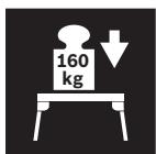
Symbols
The following symbols can be important for the operation of your saw stand. Please memorise the symbols and their meanings. The correct interpretation of the symbols helps you operate the saw stand better and more secure.

Symbol
Meaning
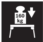
The maximum carrying capacity (power tool + workpiece) of the saw stand is 160kg .
Functional Description

Read all warning notes and instructions enclosed with the saw stand and the power tool to be mounted. Failure to follow the warnings and instructions may result in electric shock, fire and/or serious injury.
16 | English
Intended Use
The saw stand is intended exclusively for mounting the following stationary Bosch saws (as of 2009.05):
- PCM 7 3603 M01 2..
-PCM8S 3603L020.. - PCM 10 3603 L01 0..
Together with the power tool, the saw stand is intended for the cutting to length of boards and profiles.
Product Features
The numbering of the product features refers to the illustration of the saw stand on the graphics pages.
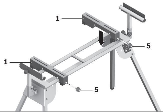
1 Attachment set
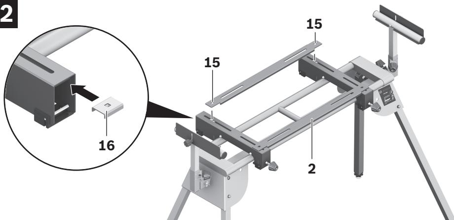
2 Retaining adapter
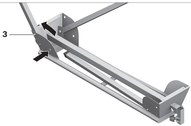
3 Locking pin of the saw stand legs
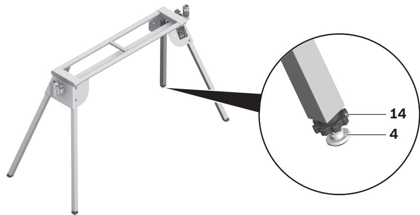
4 Height-adjustable leg
5 Locking knob of the attachment set 1
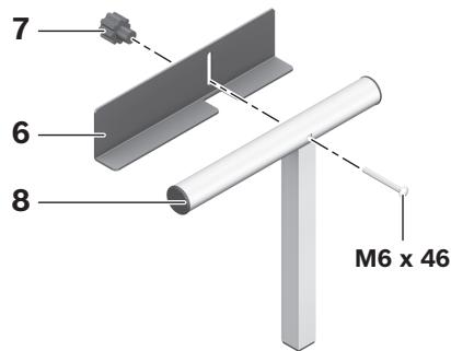
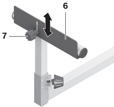
6 Length stop
7 Locking knob of the length stop 6
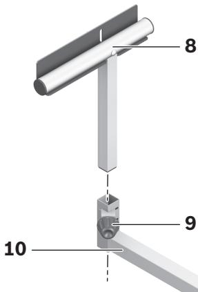
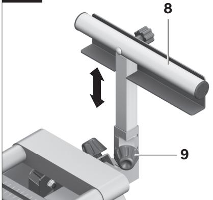
8 Workpiece support
9 Locking knob of the workpiece support 8
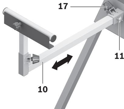
10 Table extension
11 Locking pin of the table extension 10
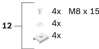
12 Fastening kit, retaining adapter
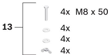
13 Fastening kit, power tool
14 Lock nut
15 Fastening hole
16 Assembly-sliding plate
17 Locking knob of the table extension 10
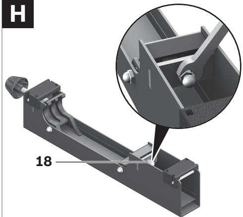
18 Adjustment screw of the attachment set 1
Accessories shown or described are not part of the standard delivery scope of the product. A complete overview of accessories can be found in our accessories program.
Technical Data
| Saw stand | PTA 2400 | |
| Article number | 3 603 M05 0.. | |
| Length of saw stand without table extension | mm | 1220 |
| Length of saw stand with table extension | mm | 2440 |
| Height of saw stand | mm | 820 |
| Max. carrying capacity (power tool + work-piece) without table extension - Attachment set | kg | 160 |
| Max. carrying capacity (power tool + work-piece) with table extension - Attachment set | kg | 110 |
| - Per table extension | kg | 25 |
| Weight according to EPTA-Procedure 01/2003 | kg | 20.4 |
Assembly
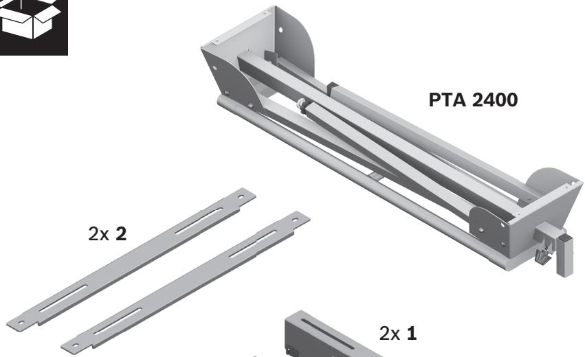
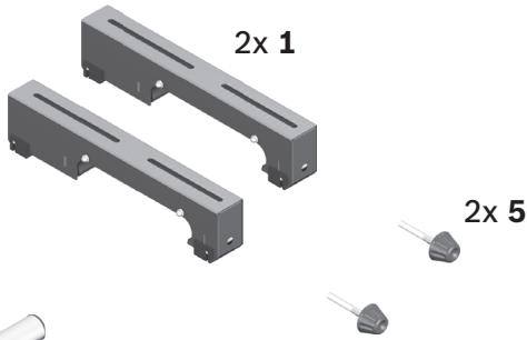
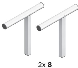
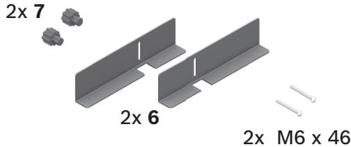
Delivery Scope

Please also observe the representation of the delivery scope at the beginning of the operating instructions.
Before assembling the saw stand, check if all parts listed below are provided:
| No. | Designation | Quan-tity |
| Saw stand PTA 2400 | 1 | |
| 1 | Attachment set | 2 |
| 5 | Locking knob of the attach-ment set | 2 |
| 2 | Retaining adapter | 2 |
| 12 | Retaining adapter fastening kit consisting of: - Assembly-sliding plate | 4 |
| - Hexagon bolt (M8 x 15) | 4 | |
| - Washer | 4 | |
| 8 | Workpiece support | 2 |
| 6 | Length stop | 2 |
| 7 | Locking knob of the length stop | 2 |
| Carriage bolt (M6 x 46) | 2 | |
| 13 | Power tool fastening kit consisting of: - Hexagon bolt (M8 x 50) | 4 |
| - Washer | 8 | |
| - Wing nut | 4 |
Additionally required tools (not in delivery scope):
- Phillips screwdriver
- Spanner
Assembling the Saw Stand
- Carefully remove all parts included in the delivery from their packaging.
- Remove all packaging material.
Setting Up the Saw Stand (see figures A1-A2)
- Lay the saw stand upside down on the floor (legs facing upward).
Push the locking pin 3 in and tilt the leg outward until the locking pin can be heard to engage. - Repeat this workstep with the other three legs.
- Turn around the saw stand to the working position. The manufacturer logo must face toward the front so that it can be read.
- Ensure that the saw stand is stable and that all locking pins have engaged.
The saw stand is easily aligned with the height-adjustable leg 4.
- Loosen lock nut 14 and screw the leg in or out until the saw stand is aligned level and all four legs face against the floor.
Mounting the Length Stop and Workpiece Support (see figures B1-B2)
- Screw the length stop 6 to the workpiece support 8 with carriage bolt M6 x 46 and locking knob 7.
- Insert the workpiece support into the table extension 10.
- Tighten the locking knob 9 to lock the workpiece support.
- Repeat the worksteps with the second workpiece support.
18 | English
Preparing the Saw Stand
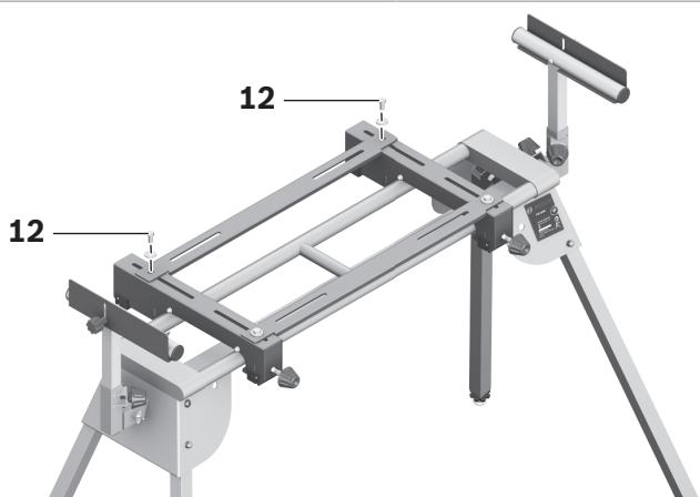
Preparing the Attachment Sets (see figures C1-C3)
- Place both attachment sets 1 on the saw stand in such a manner that the labelling can be read.
- Hand-tighten both locking knobs 5.
- Place the retaining adapters 2 with the flat side facing upward on both attachment sets and move them apart so that the fastening holes 15 are aligned.
Guide two assembly-sliding plates 16 each (perpendicular, with the flat side facing upward) from the rear into the guide compartment of the attachment sets 1. Move the assembly-sliding plates apart so that they are aligned with the fastening holes 15. - Hand-tighten the attachment sets and retaining adapters with the washers and hexagon bolts from fastening kit 12.
- Afterwards, firmly tighten both locking knobs 5 of the attachment sets.
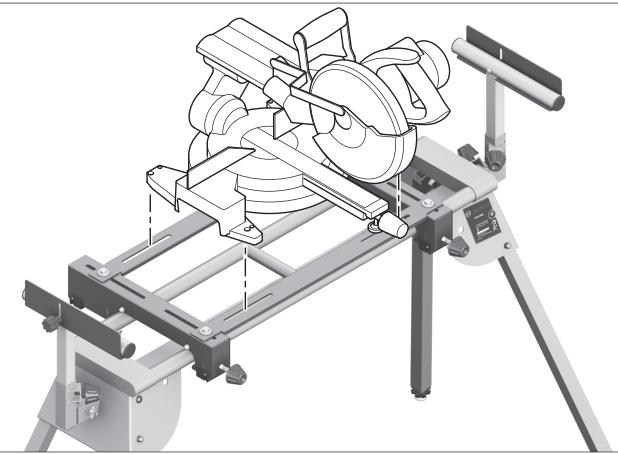
Fastening the Power Tool to the Attachment Sets (see figures D1-D3)
- Position the power tool in the transport position. Notes on the transport position are given in the operating instructions of the respective power tool.
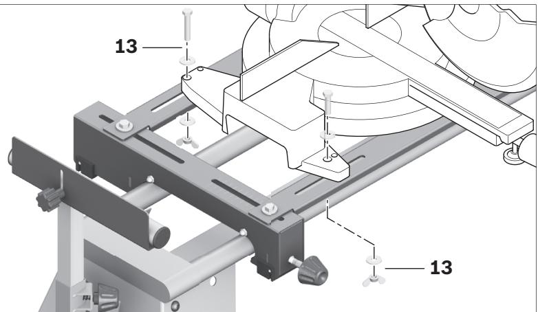
- Position the power tool on the front retaining adapter in such a manner that the front mounting holes on the power tool are brought into alignment with the slots of the retaining adapter.
- Screw the front retaining adapter and the power tool together with the hexagon bolts, washers and wing nuts from the fastening kit 13.
Position the rear retaining adapter in such a manner that the rear mounting holes on the power tool are brought into alignment with the slots of the retaining adapter. - Screw the rear retaining adapter and the power tool together with the hexagon bolts, washers and wing nuts from the fastening kit 13.
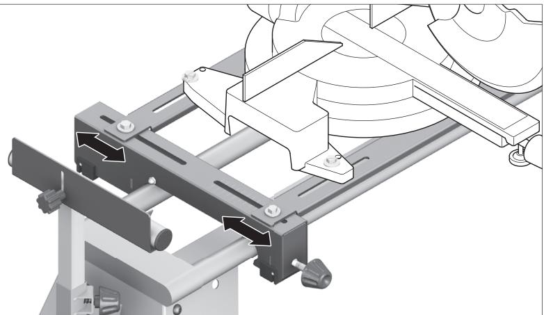
Align the retaining adapters 2 uniformly. The imprinted scale aides in adjusting the same clearance on both sides.
- Finally, firmly tighten all screws of fastening kit 12 (retaining adapter) and all wing nuts of fastening kit 13 (power tool).
Operation
Working Advice
Do not overload the saw stand. Always observe the maximum carrying capacity of the saw stand and the two table extensions.
Always hold the workpiece firmly, especially the longer and more heavy section. After cutting through the workpiece, the centre of gravity may become dislocated in such an unfavourable manner that the saw stand tips over.
If possible, always place the workpiece on one or both workpiece supports.
Extending the Saw Stand (see figures F1-F2)
Long workpieces must be underlaid or supported at their free end.
- Place your long workpiece onto the saw table of the power tool.
- Loosen locking knob 17 and pull the table extension 10 out to the desired clearance. Due to locking pin 11, the table extension can only be pulled out to the stop.
- Retighten the locking knobs again.
- Loosen locking knob 9 and adjust the height of the workpiece support 8 so that the workpiece rests level. The workpiece must be positioned level on the power tool's saw table.
- Retighten the locking knobs again.

Sawing Workpieces of the Same Length (see figure G)
The length stop 6 can be used for easily sawing workpieces to the same length.
- Adjust the desired workpiece length. (see figures F1-F2)
- Loosen locking knob 7 and position the length stop 6 to the desired clearance to the saw blade of the power tool.
- Retighten the locking knobs again.
Adjusting the Attachment-set Bracket (see figure H)
After intensive use of the saw stand, the bracket that locks the attachment set 1 to the saw table via the the locking knob 5 may possibly require readjustment.
- Remove the power tool from the attachment sets.
- Turn the attachment set upside down.
- When the attachment set cannot be locked to the saw stand despite firmly tightening the locking knob, screw the adjustment screw 18 in clockwise direction.
When the attachment set does not fit onto both rails (front and rear) of the saw stand at the same time, screw the adjustment screw 18 in anticlockwise direction.
- Check the firm and correct seating of the attachment set and repeat the adjustment, if required.
- Repeat the worksteps with the second attachment set.
Maintenance and Service
Maintenance
If the saw stand should fail despite the care taken in manufacture and testing, repair should be carried out by an authorised customer services agent for Bosch power tools.
In all correspondence and spare parts orders, please always include the 10-digit article number given on the type plate of the saw stand.
After-sales Service and Customer Assistance
Our after-sales service responds to your questions concerning maintenance and repair of your product as well as spare parts. Exploded views and information on spare parts can also be found under:
www.bosch-pt.com
Our customer service representatives can answer your questions concerning possible applications and adjustment of products and accessories.
Great Britain
Robert Bosch Ltd. (B.S.C.)
P.O.Box 98
Broadwater Park
North Orbital Road
Denham
Uxbridge
UB 95HJ
Tel. Service: +44 (0844) 736 0109
Fax: +44 (0844) 736 0146
Australia, New Zealand and Pacific Islands
Robert Bosch Australia Pty. Ltd.
Power Tools
Locked Bag 66
Clayton South VIC 3169
Customer Contact Center
Inside Australia:
Phone: +61 (01300) 307 044
Fax: +61 (01300) 307 045
Inside New Zealand:
Phone: +64 (0800) 543 353
Fax: +64 (0800) 428 570
Outside AU and NZ:
Phone: +61 (03) 9541 5555
www.bosch.com.au
Republic of South Africa
Customer service
Hotline: +27 (011) 651 96 00
Gauteng - BSC Service Centre
35 Roper Street, New Centre
Johannesburg
Tel.: +27 (011) 493 93 75
Fax: +27 (011) 4930126
E-Mail: bsctools@icon.co.za
KZN - BSC Service Centre
Unit E, Almar Centre
143 Crompton Street
Pinetown
Tel.: +27 (031) 7 01 21 20
Fax: +27 (031) 7 01 24 46
E-Mail: bsc.dur@za.bosch.com
Western Cape - BSC Service Centre
Democracy Way, Prosperity Park
Milnerton
Tel.: +27 (021) 551 25 77
Fax: +27 (021) 5513223
E-Mail: bsc@zsd.co.za
Bosch Headquarters
Midrand, Gauteng
Tel.: +27 (011) 6519600
Fax: +27 (011) 6519880
E-Mail: rbsa-hq.pts@za.bosch.com
Disposal
The saw stand, accessories and packaging should be sorted for environmental-friendly recycling.
Subject to change without notice.
Robert Bosch (France) S.A.S.
Bosch Service Center
Telegrafvej 3
2750 Ballerup
Tel. Service Center: +45 (4489) 8855
Fax: +45 (4489) 87 55
E-Mail: vaerktoej@dk.bosch.com
Bortskaffelse
Bosch Service Center
Telegrafvej 3
2750 Ballerup
Danmark
Tel.: +46 (020) 41 44 55
Fax: +46 (011) 187691
Avfallshantering
Bosch San. ve Tic. A.S.
Ahi Evran Cad. No:1 Kat:22
Polaris Plaza
80670 Maslak/Istanbul
Müsteri Danismani: +90 (0212) 335 06 66
Müsteri Servis Hatti: +90 (0212) 335 07 52
Tasfiye
Robert Bosch Sp. z o.o.
Bosch Service Center PT
K Vapence 1621/16
692 01 Mikulov
Tel.: +420 (519) 305 700
Fax: +420 (519) 305 705
E-Mail: servis.naradi@cz.bosch.com
www.bosch.cz
Zprcováni odpadú
Pracovnstul, prislustensti a obaly maji byt dodany k opetovnemu zhodnocenin neposkozujicimu zivotni prostrejd.
Změny vyhrazeny.
Bezpečnostné pokyny
Vseobecnbezpecnostnepokyny
A POZOR
Precitajte si vsetky prilozené
vystražné upozornenia a pokyny
TpHNoJxHnO K BepCTaKy M MoTHpyeMOMy Ha Hrero 3AnKtpOnHcTpymEnTy, BCE NnHcTpPyKuHN I TpeDuTpeDuTeAhBHe yKa3aHn.
HrhopopOBaHne yka3aHnI ToTexHnke
6e3oIaCHOCTn INHCTpyKcM MoKeT IprNBeCTN K 3JIeKTPnueCKOMy ydApY,IOXapy N/INN TJeKAbIM TpaBMam.
Yka3aHnI IO TexHnke 6e3oTacHOCTN ABA BepCTaKOB
Ipeed hactpoiko HNCTpymeHTa Hn 3amehbl er0 KOMIIeKtyUOxH DeTaAeH 063ateBbHO CLeAyeT BbIePHyTB BNAky TnTAIOJero Ka6EaH N3 cTeBOH po3ETKn H/HAN BbIHyTB AKKyMylTop H3 3AEKTPoHHCTpymeHTa. CAYauHbI 3aYcck 3AEKTPoHHCTpymeHTa RBAeTC PpNUHoi MHOrHX HeCuaCTbIX CUYaeB.
Правимьно установпесерстak,праздем моHTнроваь тэктponнстумент наим.Бezупецна установka о悔ь Вaxнадя п dedOTврашени OTаСHOCТи erо паденя.
HaJExKHO 3aKpeHInTe 3eKtpOnHcTpymeHT ha BepCTake, IpexJe qem HaunHaTb pa6oTaTb c Hm. CkoIbXeHne 3eKtpOnHcTpymeHTa Ha BepCTake MOxET IpiuBecTH K ITOtepe KOHTPOA HaD Hm.
YcTaHabHbAteBepCTaK Ha IpoUHOH, POBHOI rOpH3OHTaBHOI IOBepXHOCTN. EcH BepCTaK e3dnt HnI WataeTc, HeBO3MOxH0 paBHomepHo n 6e3oPaacHO BECTn 3AEKTPOINHCTPymENT Hn 3aTOtOBky.
He Ieppykaite Bepctak H He NcIOa3yIte erO B KaueCTBe AecTHNcbl Hn IOdmoCTKOB. Iepperpy3ka nn CToHnne Ha BepCTake MOrT PnIBeCTn K TOMy, UTO erO ueHTp TJeKeCTn IepemecTnTCB BBepx H BepCTak OTpOKnHeTcR.
CaeInte 3a TeM, yTo6bI Ipiu TpaHcTIOPTnOBKe Bce 6e3 NCKAUOueHINB HHTbI H COeAHNHTeMbHbIe 3AeMeHTbI 6blAN KpeTIKO 3aTAYbI. 3axHMHO KOMTIeKT 3AEKTPoHHCTpyMeHtA BCERda DOAXhen 6bITb HADEXHO 3aΦHKCpOBaH. OcA6AeHHbIe COeAHHeHIN MOrY TPINBecTHN K HeyCTOuHBOCTN H HeTOUHOMy paCNIy.
MoHTpyuTe H demoHTpyuTe 3eKTPoHnCTpymEt,TObKO KOrDa OH haxoHTcB TpaHcTIOPTPOBOOHyOM TIOLOXeHH (yKa3aHHI TPAHCIOPTPOBOOHYMOIOAOXeHHIO CM. TaKHe B NHCtPyKUnIIO 3KCTIAYataun K COOTBETCTBYUoEMy 3eKTPoHnCTpymEt). B IpoTHBOM Clyaue 3eKTPoHnCTpymEt MOKeT HAcToBko He6laorPnIbIy IeHTp TJeKctN, UTo Bb6yDeTe He B COCTOAHN HaExHO DePkaTb erO.
ПлбзугсьЗalektpoHHCTpymeHTOM, 3akpeπaENHbIM B 3axHMHom KOMTAEKe, NCKAHOHTeMbHO TObKO Ha BepCTake. Be3 BepCTaka 3axHMHOI KOMTAEKT C 3aleKTPoHHCTpymeHTOM CTONT He yctOuHBO mOxket IpeBepHyTbCra.
6eHTecbBTOM,TODANHHbIEH TAKeAble 3aROTOBKn He IINBEyT K HApyuWeHIO paBHOBecn Bepctaka. PoC bO6oHNbIe KOHcbldNNHbIX N TAKeAblx 3aROTOBOK CLeAyeTTO-HN6yAb ToKlaDbIiBaTb HAn HAdo IOdPiNaPbTb.
CHMBOAbi
Cleyuüne CmBOIb MOyT 6bl BaXhbl Ipi
3KcNpyataunn BaWero BepCTaka. PoXaLyHCTa,
3aTOMHInTe CmBOIb INx 3HaueHne.
PipaBnIbHa nHTePITpeTaunr CmBOIoB TOMoXet
Bam Lyuwe H NaExkHe NcToA3OBaTb BepCTak.
CHMBOA
3haeHne
MaKcImaIbHaHa HaRpy3OuHaN cTIOco6HocThB BepCTaka (AeKTponHCTpymENT + 3aorTOBka) coCTabAAET 160 kr.

OtticaHne yHKcHH

Пючтайтевдokум entaunn, trpoLoxehHoi K Bepctaky m OHTnpyemomy Ha Hero 3aleKtpoHnHCTpymEnTy, Bce HNCTpyKUnn N IpeDuTpeDnteBhbIe yka3aHn.ИrhoproBaHne yka3aHn IO TeXhNeke6eOtnacHoctn INHCTpyKUn MOKeT pInbEcTN K 3aleKtpuYeckOMy ydApy, Toxkapy n/HAN TAgKeMbIM TpaBMam.
Yka3aHnI IO TpHMeHeHHO
He perepykaTe Bepctak. Bcerda TomHnTe o makcmaIbHoH HeCyuei CTOOC6HOCTn Bepctaka n 06oHX ydHnHTeJe CTota.
Bcerda xopo0o 3akpeenIyte 3arotOBky, oc6eHHo 6oIee TjKeAlyO dHnHyO ee YaCTb. IocLe OTpe3aHnI 3arotOBKn cHTp TjXeCTN MoKet CMeCTNbC HAcToAko HeydauHo, yTO BepCTaK MoKet OTpOKnHyTbCra.
TIO BO3MOXHOCTHn yKlaabBaIte 3arotOBky Bcerda Ha ONDy Nn Ha o6e onopbl.
YdHHeHne Bepctaka (cm.pnc.F1-F2)
Cbo6oAnbI KOHeI dHnHbIX 3aTOTOBOK DOJXeH IeKaTb Ha OTope.
- YctaHOBnTE dHHHyo 3arOTOBky Ha cToIe 3AekTpOuHCTpymEnta.
Ocna6bTe pykyΦnKcaunu 17 n BbITaHHTe yAHHInTeIb CToLa 10 HApKy Do XeAemorop pacCToRHN. BaIroapr CTOpOPHomy wTnФTy 11 yAHHInTeIb CToLa MoXHO BbITaUHTb TObKO do yToppa. - Choba kpekn0 3aTnHte pyky fnkcaun.
- Ocna6bTe pyky finkcaun 9 n oTpeyIpyTe BbICOTy OTOpblAa3aTOBKn 8 TaKIM O6pa3OM, YTO6bl 3aTOBKa paacnOlaRaalacb poBHO.
3aIOTOBKa DOAnKHa IeKaTb POBHO HA CTOnE 3AEKTPoINHCTpyMeHTa.
- Choba KpeIko 3aTnHnte pyuKy fHKcaunn.
06pe3 3aROTOBOK OAnHaKOBoI AINHbI (cm.pnc.G)
AIIIPOCTO OTe3aHn 3aTOrTOBOK C OAnHaKOBoD AnHO BbIMoXeTe NcTIOb3OBA Tb IPOAOHBHy yIop6.
- OTPerynpyTe Heo6xOaMMyU OAnHy 3arotobKn. (cm.pnc.F1-F2)
Ocna6bTe pyky dKcaun7 npacnooxKeTIpOdoHbI yTOp 6 Ha HxKHom pacCToHnOT TINbHOrO DnCKa 3AeKTponHCTpyMeHTa. - Choba KpeIko 3aTnHnte pyuKy fHKcaunn.
PeryAnpOBKa cKo6bI 3aJxHmHorO kOMTAEkTa (cM. pnc. H)
При Heo6xOAMMocTN IocLe HHTeHCBHOI 3KcIIyatauIN BepCTaKa HUxHo OTepyAInpOBAt b CkO6y, c TMOObIO KOTopoJ 3aXHMHOI KOMTIeKT 1ФHKCnPyETc pyUKO fHKcauN 5 Ha BepCTake.
- YdaIaIte 3eKtpoHnHcTpymeHT n3 aXmHbIX KOMTIAEKTOB.
-ПepeBepHnTe 3axHMHOI KOMTIAKeT.
ПовернITE потов уасов CTpeкп peунровьи BINT 18, ecn 3axmною KOMПЯКТ HeCMOTРЯ Ha KpeTko 3aTЯHytle pyukn Фнкацин He Фнксируетя на Верстake.
TObepHnTe IpOTnB YacOBoC TpeAkn peYAnpoBOUhbl BVHT 18,ecN3axmHbI KOMPTeKHe caANTcOHOBPeMeHHo Ha oBe peHKn (IpeEaHIOu N3aHIO) BepCTaka.
3o6paxehi KOMTOHEHTN
Hymepaia 3o6paXeHHK KOMTIOHeHTIB TocnAeTbcra Ha 3o6paXeHHBepCTaka Ha CTOpIHkax 3 MaIIOHKamn.
1 3aTnCKHn KOMTIeKT
2 3aTnCKHn aadTnTeP
3 CToIopHnI WTHI HIR Bepctaka
4 PeryaBoBaHa IIO BnCOTi Hixka
5 PyuKa ikcaui 3aTnCKHO KOMTIaekTy 1
6 TOn3oBxHnYtOp
7 Pyuka pfikcauii n03oBxHboro ytopa 6
8 Onopa 3arotobkn
9 Pyuka fikcaui otopn 3arotOBkn 8
10ItoDObKyuBaCToLa
11 CToIopHnI uTnOITIOOBKByBaCA cTOna 10
12 MoHTaXHH KOMTIAEKT 3aTHCKHO aAaTTepa
13 MoHTaXHHK KOMTIIeKT eAeKtPoIpPnAaDy
14 KOnTpraKa
15 KpiHnAbHn OTBip
16 MoHTaXHa HaKaIaKa
17 PyuKa pfikcauiI IOdoBxBya cToIy 10
18 PeryaHOBaBHH TBNHT 3aTnCKHOro KOMTAnEKTo 1
3o6paXeHe a60 OTHcAHe pHnAAdA He BXOaHTb B cTaNapTnH o6cra TIOCTABKn. IOBHN acOpTmEHT pHnAAdBA H3aIeTe B haui IIpOprpami pHnAAdA.
Tpiu3HaueHH npuHa
Bepctak IIpH3HaueHn IAM MOHTaJy Ha HbOMy BKNLHO TAKNX CTauioHapHnx IINoK BInpo6HnTBA Bosch (CTahOM Ha 2009.05):
- PCM 7 3603 M01 2..
-PCM8S 3603L020.. - PCM 10 3603 L01 0..
B KOMTIAEKTI 3 eAEKTOPIPNAAM BepCTaK IpiH3aHeHn DAp PO3KPOIO DOoOk i IpophiAIB.
TexhiHi daHi
| Верстak | PTA 2400 | |
| Товарни homер | 3 603 M05 0.. | |
| Довхина верстaka 6е3 ПОДВЖУBAча StOу | MM | 1220 |
| Довхина верстaka 3 ПОДВЖУBAчem StOу | MM | 2440 |
| Висota верстaka | MM | 820 |
| Мамс. Нecuya здатнICTь (elektroponprilad + 3arotobka) | ||
| 6e3 ПОДВЖУBAча StOу | ||
| - 3aTHSCHи KOMПLEKT | КГ | 160 |
| Мамс. Нecuya здатнICTь (elektroponprilad + 3arotobka) | ||
| 3 ПОДВЖУBAчem StOу | КГ | 110 |
| - 3aTHSCHи KOMПLEKT | ||
| - кожни ПОДВЖУBAч STOу | КГ | 25 |
| Bara BiДпоВідно Do EPTA-Procedure 01/2003 | КГ | 20,4 |


MOHTAX
06cgr TIOCTaBKn

AIB.06cIITIOCTaBKn,I03a3NaueHnHaIOuATkyIHCTpyKii3ekCIIyatauii.
Ipeed MOHTaxem BepCTaka IpeebiPe T haBhictb BCix HnKye3a3NaueHx DeTaAe:
BctaHOBLeHHB BepCTaka (Aub. MaI.A1-A2)
-Поклады Верстak ДогориHoramnHaпдагу.
-ПинсИт b cTOnOpHn WtNФТ 3 BcepeAnHy Ta BnBepTaIte HORY hA3OBHi, DOKN cTOnOpHn WtNФT 3HOBy He BBiIe BiAHTHO y 3aueTIIeHH.
- TOBtopiB zuo pObouy oIepaizIO 3 iHsIMn TpbOMa HorAMN.
- PpeBepHitb Bepctak Bpo6ooyoToLoXeHHA. IOrOTnBnPo6HnKaIOBnHeh 6yTH pO3mIeHn CpepeDy taK, Oo6 NOrO MoXHa 6byo IpoounTaH.
YTeBHTbCByTOMy,OBoBepCTaK yCTaHOBHeHnCTa6IbHoTaBCiCTOnOpHi 1TNΦTN YBiMnB3auePHeHH.
PerybObaHa IIO BnCOTi Hixka 4doIOMoKe Bam BnpiBnHTN IIOJooHeHHBepCTaka.
Bikpytib kohtprayky 14 i Bikpyuyte a6o 3akpyyTe HIXKY D0TN, TOKN IIOLOXeHHa Bepctaka He BnipIBHReTbc i BCi YoTPn HoHn He 6ydyTB cToTn Ha IIIO3i.
MOHTAX IIO3AOBxHbO YoIopTa OTOpN 3aROTOBKN (ANB. MAIOHKn B1-B2)
- PnKpyiTb T03doBxHi yTOp 63a DToTOMOIOI rBNHTa M6 x 46 i pyuKn φikcaii 7do OTOpN 3aTOtOBKn 8.
BCTaBTe OToPy 3aToTOBKn B IIOoBkByBaCy CTOny 10. - DnA φikcaii onopn 3arotobkn 3atraHITb pyky φikcaii 9.
IIOBtopitb zi po6oqi Otnepaui 3 dpyroO OTOPOIO 3aorTOBKN.
TiiADROTOBka Bepctaka
ПлгOTOBКа 3АТССНО КOMПАЕКТУ (ANB. MaA. C1-C3)
- YctaHOBIb 06nBa 3aTnCKHI KOMIIeKTH 1 Ha BepCTaky TaK, 0o6 HADINCS MoXHa 6yIo IpouHTaTn.
- Cλa6o 3aTgHITb 6nΔBi pyuKn φikcaui 5.
- YctahOBiB 3aTHCKHi aAaTIpeRn 2 pIBHm6Okom yropy Ha 0bIaBA 3aTHCKHI KOMIIeKTHTa IocyHbTe ix HactiakN, IIO6 BOHN3HaXoDHNCr Ha KpITINbHMn OTBOPAMn 15.
BCTaBTe DBI MOHTaXHi PANTN KOB3aHH 16 (yTonepeK, PLOCKHO CTOPOHO yrOpY) 33aDy B HAIPMHy YAcTHHy 3aTnCKHx KOMTAEkTiB 1. TocHyTe MOHTaXHi PANTN KOB3aHH HaCTiAkhN, IIO6 BOH N 3HaXoANHCra HaK pIINbHMn OTBopam 15.
Cλa6o ckpinitb 3aTnCKHn KOMTAEKT Ta 3aTHCKHn aAaTep 3a DOITOMOIOIπkλaDHnx WaB6 Ta TBNHTIB 3 WecTnRpaHHO ROAOBOHO i3 MOHTaXHOrO KOMTAEKTOY 12.
-ПOTIMЗатягнітьобиді ручкіфікацій 5 3aTNCKHOrO KOMTIAkTeY.
3aKpiIeHH eIeKToPpHAAy Ha 3aTHCKHOMY KOMIIeKTI (AHB. MaA. D1-D3)
BcTaHOIBtbeAeKtpoPpHnAA B TIOLOXeHHRA DnTpaHCtOpTyBaHn. Bka3iBKN 0do IOLOXeHHNDA TpaHCtOpTyBaHHn Bn 3HaIaTe B iHCTpykui 3 eKcPiyaTaui Do BiIOBIDHO eAEKtpoPpHaay.
PozmicITb ekeKtppnaHa napehboMy 3aTHCKHOMy aAANTepi TaKHM uHHOM,IO6 PtepeHi MOHTaxKi OTBOPn Ha ekeKtppnaadi CIIIBTaaAaN 3 DOBtractHM NOTBOPAM 3aTHCKHOro aAANTepa.
3'εΔHaηTe ΠepeΔHη 3aTnCKHn aαaΠερ Ta eλεKTPOπPnλA 3a ΦΟΓOMOΓΟ ΦBHTIB 3 ΦεCTNΓρaHNO ΦΟΒΚΟ, ΦιΑΚΑΔΗΝΧ Φαδ6 Ta rαοκ-6apahuNKiB i3 ΜΟΤαχΗΟ ΓΟΜΠλΕΚΤΥ 13.
IpecyhBe 3aHi 3aTHCKHn aaaaTep TaK, 0o6 3aHi MoHTaxHi OTbOp Ha eAeKTPoPiHaI cIIIBTaI N 3 DOBraCTHMN OTbOpAM 3aTHCKHO aaaaTepa.
3'εΔHaIte 3aΔHn 3aTHCKHn aΔaITep Ta eAeKTPoIPnAA3 3a D0TOMOFO TBrNTIB 3 WecTnrgpaHHOIO rOLOBKOIO, PIAKlaADHnx Wa6 Ta raioK-6apAHuNKiB i3 MoHTaxHO KOMTIaEKTy 13.
PIBHOMIPHO BnIPBHHaTE 3aTNCHi aaIITepn2. HaHeceHI IO3HauchN Ha IkaJI DOITMOxTyb Bam BiAperyIIOBaTN ODAKOBy BiCTaHb 3 6oX 60kIB.
Ha 3aBepseHHe 3aTgHtB BcI rBnHTn MOHTaJHoTO KOMIIeKTy 12 (3aTNCKnH aadTep) Ta BcI raKn-6apAHuKN MOHTaJHoTO KOMIIeKTy 13 (eLeKtpoPpHnAaD).
Pobota
Bka3iBkn 0oDo po6oTu
He IpeBaHTaJxIe BepCTak. 3aBxMn 3BaKaIte Ha MaKcMaMaIbHy HecuYy 3aTHicTb BepCTaka i o60 X IOoBxKyBaIb CToIy.
3aBXM MIO HO pHrPMMyTe 3aROTOBky, Oc06bNO II 6IbW BaxkN DOBn KHeu. Iicra TepeTINHOBAHH 3aROTOBKn CEHTp Barn MoKe 3mICTHTnc HAcTIbKn HeCPTPnAITNo, IO BepCTak MOKe TpeBepHyTncr.
TMOKANBOCTI KlaAdItb 3aOrTOBky 3aBxHn Ha oHy a6o Ha oNAbi OToPi.
Побовские Верстaka (ДИВ. МА. F1-F2)
Pn o6p06i DOBTHx DeTalee Niix BihNkHeu Tpe6a 1o-He6ydb Nklaactn a6o NiIeptnnooro.
- POKλaɪtB doBry 3aʊTobkU ha CTɪn eʌkTePɒpɪnʌd.
Biynty pyky fikcaui 17 ta BHTIb IIOOBxByau CTOly 10 Ha Heo6xHy BiCTaHb. 3aB4Kn CTOpHomy tTu 11 IIOOBxByau CTOla MoXHa BNTTHyTN ANWe DO yTopy.
3HOby 3aTnHiB zu pyuKy iKcauii.
Bicnytbypkyfikcaii9iBiperyuoyte BnCOTy onopn 3arotOBKn 8 Tak,io6 3arotOBKa IeXaIa IIpRAmo. 3arotOBKa IOBVHHa IeXaTHPiBHO Ha CTOnI eekTpoPPnAay. - 3HOby 3aTgHitb zu pyky fikcauii.


P03IIIOBAHHaROTOBOK OHaKOBOIOI DOBXHH (AIB. MaI. G)
AIIIPOCTORO PO3IIIOBAHH 3aIOTOBOK ODAHAKOBIOI DOBKNHN MOJHa BIKOPNCTOBYBATH IO3AOBKHIN yTOp 6.
BctaHObITb Heo6xIDHy DOBXHHy 3aTOBKN. (ANB.MaI.F1-F2)
BIDnyctitbpykyfikcaii7TaBCtahOBiTB IO3IOBXHIIyTOp6HaBIIOBIAHy BIDCTAHB BIDIINABHOHO DnCKaEAEKTOPIPnAay.
- 3HOby 3aTgHitb zu pykuy fikcauii.
PeryAUbaHHaYXKN 3aTHCKHORO KOMIIeKTy (MnB.MaN.H)
Iicra iTeHCBNHOi EKcTIyatauBepCTaka MoKe 6ytn IOTpi6Hm BiDpeRyHOBaTH dyKy, RaKa ikcy 3aTnCKHn KOMPiKeT 1 3a DOnOMoTOO pyuKn ikcaui 5 Ha BepCTaky.
- 3Himitb ealektpoopnla3 3aTHCKHX KOMTIAeKtIB.
- IpepeBepHItb 3aTnCKHn KOMTAEKT.
IIOBepHitbpeRyIOBaIbHNrBHT 183a cTpiAkoTOroDHHNka,RAKIO 3aTnCKHN KOMTIaekT,He3BaJauOuHa CnIbHe 3aTAYBaHHpyuKnΦiKaui,HeΦiKcyETbcra Ha BepCTaky.
Поверніт bperуИюВаьнг rBnHT 18 npotn ctrpiKn roaHnHnka,якso 3aTnCKHn KOMIeKt He ciAe OJHOuacHo Ha o6nDi peiKn (3aDnO i IpeEaHNo) BepCTaka.
IpebeipTeMiunHicTB Ta IpaBnBnHicTB IocaKn 3aTnCKHOrO KOMTIAeKTy Ta 3a Heo6XiHicTH OTOBtopiB Ipoueedpy peyuIOBaHH.
Iobtopitb zi po6oqi onepaui 3dpyHM 3aTHCKHIM KOMPiAeKToM.
Texhuihe 06cIyroByBaHHa cepBic
Texhiue 06cayrobyaHHA
Ykso He3BaKaIOUH Na peTeIbHy IpoueDpy BnTOOBLeHHN i BNpO6yBaHHBepCTak BCE-TaKu Bnnde 3 Aady,peMOHT MaE BVKOHyBaTH NlWe MaJCTepH, aBTOpH3OBAHa Dn eKeTPOiHcTpymentIB Bosch.
При BCIXdoDAtKOBINx3aINTaHHxTa 3aMOBAEHHi 3aTnactH,6yDbIacKa,3a3NauaTe 10-3NaHnH NHomepAIA 3aMOBAEHH,IO CTOITb Ha 3aBOOcbKi Ta6AnuCi BepCTaka.
CepBicHa MaicTepeH i 06cAyroBvBaHHKlaieHTiB
B cepbicih maictepHi Bn OTPmaeTe BiIIObiBa ha BaWi 3aPiTaHHA CTOCOBHO peMOHTy i texHIO HorO o6cLyROByaHHa Baworo pOdykTy.
MaIOHKn B DeTaIaX iIHΦopMaIciU ⅢOo 3aIuacTIN MOnHa 3HaItn 3a aDpecoIo:
www.bosch-pt.com
KohcybTaHTB Bosch 3 paAdicTIO DOIOTOMOxyt BAm IpiN 3aINTAHHx CTOCOBHO KyiIBI, 3aCTOCyBaHN i HalaorDxKeHHIPOyktiB i PnlaADo DO HNX.
YkpaHa
Bou CepBic LENTp EAnKtpoHCTpyMeHTIB By. KpaHn, 1, 02660, KnIB-60
TeA.: +38 (044) 5 12 03 75
TeA.: +38 (044) 5 12 04 46
TeA.:+38(044)5120591
a c: + 38 (044) 5120446
E-Mail: service@bosch.com.ua
Aapeca PeriohaBnHex rapaTiiHnHex cepBichix MaicTepeHb 3a3HaueHa B HaioHaBHomy rapaTiiHOMy TaIoHi.
Ytnaiauaia
Bepctak, pinnaa i ytnakOBky tpe6a 3daBaTHnHa ekoIorHNo nCTy NIOBtOpy nepepo6ky.
MOXANBI 3MiHn.
110 | Roman
Bosch Service Center
Str. Horia Macelariu Nr. 30-34,
013937 Bucureşti
Tel. Service scule electrice: +40 (021) 4 05 75 40
Fax: +40 (021) 405 7566
E-Mail: infoBSC@ro.bosch.com
Tel. Consultanta tehnica: +40 (021) 4 05 75 39
Fax: +40 (021) 405 7566
E-Mail: infoBSC@ro.bosch.com
www.bosch-romania.ro
Eliminare
Masa de lucru, accesoriile si ambalajele trebuie directionate catre o statie de reciclare ecologica.
Subrezerva modificarilor.
Yka3aHnna 3a 6e3oNaChpa60Ta
06uynka3aHna 3a 6e3oNa cha pa6ota
A BHIMAHNE IpoeTeBCHKn IpeDyIpyEKeHn H yKa3aHn
KaKTo KbM CTeHda, Taka N KbM
eNeKtponHCTpyMeHTa, KoiTo ue MoTHnpate Ha
CTeHda. IpnOynckn IIpiN CnA3BaHeto Na
yKa3aHaHrTa 3a 6e3oIacHa pa6ota n 3a pa6ota c
eNeKtponHCTpyMeHTa MOrA dI pPeDn3BnKaT
TOKOB yDap, IOnXap N/IN N TeXKn TpaBMn.
Yka3aHn3a 6e3oTncha pa60Ta cbc CTeHDoB
Ппедида започeteда Habстpoьвate eilektponHHCTpymeHTa Идда Заменгет pa60THHn HNCTpymeHT,ИЗКALOчBAite ueTceLa OT KOHTaKTA,peCt.ИЗВaxДаTe akymyAToPnHATA 6aTePnO t eilektponHHCTpymeHTa.Yecta пpruHa 3a TpydOBN 3IoTOlykIn E BkLIOUByAHeTo Ha ealekTopnHHCTpymeHTa ITO HeBHMmaHne.
PpeHd a MoHTnpaTe eAeKTPoHHCTpyMeHaTa, crAo6eTe CTeHda HATbHAn H IpaBnHNo. Be3yKOpHTo cTlO6BaHe e BaxHo, 3a da IpeDoTbPaTIne OtacHocCTTa o Pa3rAo6BaHe ITO BpeMe Ha pa6ota.
Ппедида започе рабota сеелктуоннструмента, ce уberяbaite, ue e 3akpehen KbM cTeHda 3dpaBO.Прпльзванeto Ha eelктуоннструмента ВCTeHda можеда ппсдИЗВИКа 3aу6aHa KOHTPOI NaД HeRo.
IocTabete CteHda Ha TBbpda,paBHa HoxpH3OHTaHa IOBbPxHOCT.AKO CTeHbT MOKe Da Ce I3MeCTBa Hn He CTbPiBa CTaBnHO C yETnpTE CN Kpaka, eLEKTOINHCTPymeHTbNn O6pa6OTBaHHrT DeTaHnHe MoRat Da 6bDaT BODeHN CnHypho npaBHomePHo.
He IpeTOBapBAHTe CTeHda; He ro H3IOA3BaHTe 3a CtBb6a HAn KaTo CKeIe. IpeTOBapBAHeTo HAn CTbIIBaHETo Bbpxy CTeHda MOxte Da IIpeDn3BnKa H3MeCTBaHe Ha ueHTbpa Ha TeJecTta My HaRope HAcTpaHn O6pbUaHETo My.
Питрансторpaneхи korato pa60nte,ce ybepeBaIte, Ye BCNUKN BnHTOBe n CbeAHHNTeHn eLEMEnTH ca 3aTeHnat 3apBO.MontaxKnTe rpeHn 3a eektpoHHCTpymehTa Tpr6Ba BnHaHn Da ca 3actOnOpEn CT6HNo.Pa3xla6eHnTe CbeAHHeHn MOrTa DA IIpeHn3BnKaT HeCTa6HHOCT HHeTOUHOCT Ppi pr3aHTo.
MoHTnpaTe n demOnTHpaTe eKTPoHnCTpymeNTa cAmO KOrato ToE B ITo3uN3a TpaHcTOpTnPaHe (3a yKa3aHn 3aIIO3uN3a3a TpaHcTOpTnPaHe BVXTe CbIo pBKOBOAdCTBOTO 3a EKCTAoatauHa CbotBETHH eKTPoHnCTpymeNT).B IPTOBEN CAYaE Bb3MOxHO CEHTpbT Ha TeJecTTa Ha eKTPoHnCTpymeNTa Da E B ITO3uN3, Pn KOrTO eKTPoHnCTpymeNTbT He MoKe Da 6bDe 3aDbPxah CnHypHo.
Ползайтабхваим Кьм могтохнITE rpeДи ealeKtpOHCTpymeNT caMo KOraTO Te ca 3aterHaTN KbM cTeHda,MOHTaXHnTE rpeДи He ocHryprBaT CTabHIOCT Ha ealeKtpOHCTpymeHTa.
YbepBaIe Ce IpeBbapHTeALHO, Ye bAIn N TeKKn DeTaiN HMa Da N3MeCTaT ZeHbpa Ha TeXecTTa Ha CTeHda N Da rIpeO6bpHaT. CBo6oHNte KpaNsa Ha dAIn N TeKKn DeTaAn Tpr6Ba Da 6bDat PoADnPaH N ToPOxO4AuHaHn.
CHMBOAH
CnMBOIHTe IIO-DOy MoRat Da 6bDaT BaxKn 3a
IpaBnHaTa pa6Ota C Baunr CTHeD. MoA,
3aTOMHETe CNMBOIHTe H3NaueHHeTO IM.
IpaBnHOTo INTEpIpeTpHaPe Ha CNMBOIHTe Ie
Bn IOMOrHe Da N3PiOn3BaTe CTHeDa IIOeΦeKTHBHO N IO-6e3OJaCHO.
CMBOA
3haeHne
MaKcHMaHaHaTa TOBapOHocMocT (eAeKtpOnHCTpyMeHT + detaI) Ha cTeHa e 160 kg.


Функуновано описане

Пючete BCnukn
ПпeДупгжденя n yka3aHnna
КаКTO KbM CTeHdA, Taka n KbM
eLEKtpOnHCTpyMeNTa, KoITo ige
MOHTnpaTe Ha CTeHda. Пюпсkn
ПиСТЯЗВaHTo Na yka3aHnYTa 3a
6e3OpiacHa pa60Ta n 3a pa60Ta c
eLEKtpOnHCTpyMeNTa MoRat Da
ПпeДиЗВИКaT TOKOB yap, Toxap
n/Hn TeKKn TpaBMn.
Ппдназачение на eAnektpoHHctpymenta
CteHbTe IpeHa3HaueH 3a MoHTnpaHe cMo Ha CLeHnTe UINPKyIaRPhMaIHH Ha BoW (cbCToRnHe KbM 2009.05):
-PCM7
3603M012..
-PCM8S
3603 L02 0..
-PCM10
3603 L01 0..
3aεHo C eIeKTpOuHCTpyMeHT CTeHbT e
πpeHa3HaueH 3a HaπpeuHO p3aHe Ha δbCKn I
πρoΦnI.
H306pa3eHH eAeMeHTn
Homepupaheo Ha n3o6pa3eHnte elementn ce OTHacrdo hnyprnte ha cTeHa RaPauuHnte cTpaHn.
1 MoTaNrpeN3a eAeKtpOnHCTpyMeHa
2 MoHTaxeH aaTnTop
3 OcnhyprnteIen ⅢnΦT 3a KpaKaTa Ha CTHeHa
4 Peryannpyem IO BncounHa Kpak
5 3actoTOpRABaIpa pbKoxBAtKa Ha MOHTaKHITe rpeiN 3a eAekTpOHHCTpyMeHTa 1
6 Haabxha onopa
7 3actonopraBaua pBkoxBaTa Ka 3a orpaHnUHTeIa IIO bAknHa 6
8ПоДпоразобарбтваньдетаи
9 3actonopraBaanda pbkoXBaTKa 3a IIOIopata 3a o6pa6oTBaHnA DeTaI A8
10 Pnncno6eHne 3a ydkaBaHe ha pa6oTHnI PAOT
11 OcnrypnteAen ⅢnΦT 3a yDbAKnTeAHa pa6oTHata Macata 10
12 KomTneKT KpeTteKHN eAeMeHTn 3a MOHTaxHe aaTTop
13 KomTIAeK TKeIeJxHn eAeMeHTn 3a eAeKTPOINHCTpyMeHTa
14 KOnTpa-raKa
15ПисьeаннHTeAneHOTBOP
16 MoHTaXHaIIaHka
17 3actonopraBaupa pbkoxBaTka 3a ybXHTeHa pa6oTHnI IOT 10
18 Peryu npa BnHT Ha MOHTaXHnTe rpeDn 3a eAeKTPoOHCTpyMeHaTa 1
H3o6pa3eHNte Ha fHyprhte H OTncaHNTe OOTbAHNTEAHN PIPCHTOOC6AeHNe H ca BKAIOUeHb B cTAHApTHaTa OKOMTIaKToTBKa HA ypeDa. N3eepNaTeeH CTNCbK Ha DOTbAHNTEAHNE PIPCHTOOC6AeHNe MOKeTe Da HAMEPNTe CBoTBEtHO B KATAIORA H N 3a DOTbAHNTEAHN PIPCHTOOC6AeHNe.
TexHnueckn daHHN
| Стetedа | FTA 2400 | |
| Каталожен Homep | 3 603 M05 0.. | |
| Дыжина на стetedа 6e3 удьлжаванe | mm | 1220 |
| Дыжина на стetedа с удьлжаванe | mm | 2440 |
| Височина на стetedа | mm | 820 |
| Мамс. Товаронocимоct (еlektroponнструмент + образовдан detай) 6e3 удьлжител - Монтajши ггеди за elektroponнструмент | kg | 160 |
| Мамс. Товаронocимоct (еlektroponнструмент + образовдан detай) c удьлжител - Монтajши ггеди за elektroponнструмents | kg | 110 |
| - на удьлжител | kg | 25 |
| Maca сбгальicho EPTA-Procedure 01/2003 | kg | 20,4 |
MOnTnpaHe
OKOMTIAEKTOBka

Moi, BxTe n3o6paxeHneTo Ha OKOMTIeKTOBkata B HauaLTo Ha pkoBOdCTB0To 3a ekTlOaTaun.
Ipea 3aTOnHeTe CTo6BaHTo Ha CTeHda TPOBepTe DaAN BCnUKN H3bpoEHN I0-DOy eAEMENT Ca HAUNH:
Otpra3BaHe Ha eHaKBO dIaIaIaIaI (BnXTe pHypa G)
3a aeCHOTO OTPaBaHe Ha DaTeaMn C eHaKBa
AbxHnHa MoKeTe Da N3IOA3BaTe OppaHnHTeA
TIO AbxHnHa 6.
HactpoTeKeHaHaTaDbAeknHaHaDeTaIa. (BxTe fngypn F1-F2)
Pa3BnTe 3aCToOpRaBaata pBkoXBAtKa7 HaCTpoIe OrpaHnHTeA IIO DbAKnHa 6 Ha JeLaHOTo pa3CTOarHne OT UINPKyAerPHn DaCK Ha eEAEKTPoHnHCTpyMeHtA.
- OTHOBO 3aTeHHeTe 3aCTOnOpRAuTa Ta pbKoXBaTka.
Perynpahe Ha cko6aTa Ha MOHTaXHnTe rpeu 3a eLeKtpoHcTpymeHT (Bxxte fHyrgpa H)
CLeI INTeH3INBHa yIIOptpe6a MoKe Da ce HaLoXn peRyInpaHe Ha cKo6aTa, KOrTo 3axBa7a MoTAtxHIne TpeAn1 KbM CTeHda C POMOHTa Ha 3aCTOITOPBA7aTa pbKOXBATka 5.
ИЗваде Te ealektpoHCTpyMeHTa MOHTaXHHTe rpeDN.
- 3aBbPTeMe MOHTaxxHaTa rpeda.
- Ako BbIpeKn CnHHOTo 3aTЯRaHe Ha pbkOxBaTKaTa MOHTaXHaTa rPeDa He ce 3aCTOIIOPRABa 3dpaBO KbM CTeHda, 3aBbPTePe pyIlnpaUaNBA BVNT 18 IO NocOKa Ha yaCOBHNIKObA Ta CTEpAka.
AkoMOHTaXHaTa rpeDa He MoXe Da 6bDe 3axBaHaTa eHOBpEmHo KbM DBeTe HaIpeuHNrpeDN (PpeHaTa N 3aHaTA) Ha CTehda, 3aBpTepeYnpaunBnHT 18 06paTHo Ha YacOBnKOBaTa CTePAka.
- ПобереTe Дали монтайнITE греди могат Да ce 3axBaHaT правинои 3драВО и Ппн Heo6xOДИМОCT пOBTOpeTe Горнite CTbПКИ.
-Повторе горнente CTытки 3a Втора моHTахнаду.
Подьржан ecpви3
TnDApbXkaHe
Ako BbIpeKn Ipeuzn3HOTI pOnH3BOADCTBO HBNMaTeAHO n3NTBaHe CTeHbT Ce TIOBpeAn, peMOHTbT Tpr6Ba Da 6bDe n3BbPWeH B OToPiHaCepBn3 3a eAleKTPoHnCTpyMeHTn Ha BoW.
Korato ce 6pbuata C BbIPOCN KbM
IpeaTbInTeHnTe Ha Boi, BnHaHn IIOcoUbaNte
10-uaPepHHaKaTAlOxeh HmOp Ha Ta6eAkaTa Ha CTehAa.
CepBn3 n KOHCyUtauH
CepBn3bT Ⅲe OTROBOpH Na BbIpiocnte Bn OTHOCHO peMOHTN IIOADpbXka Ha 3aKyuTeHH NOrBacIPOyKT, KaKTo N OTHOCHO pe3epBHN qAcTn. MoTHaTKHN cepTeKN HhOpaMaJna 3a pe3epBHN qAcTn MOKeTe Da HamePte CbIo NHa
www.bosch-pt.com
EknTbT OT KOHCyIaHTn Ha BoW ige Bn IIOmOrHe C yD0BOACTBVe PnB BIIpOCh OTHOCHO3aKpyBaHe, PpILOXeHne H Bb3MOxHOctn 3a HAcTpoBaHe Ha pa3AnuHN IPOdYKTn OT IPOH3BOcCTBeHata rama Ha BoW n DOITbANHTeHn PnHcTTOco6LeHn 3a T8x.
Po6epr Bous EOOD- BbIrapn
BoucpeBn3JeHbP
IapaHOnOHn I3BbHrapaHcNoHHn peMOHTN
yI.Cpe6bphNa No 3-9
1907 Codner
TeA.: +359 (02) 962 5302
TeA.: +359 (02) 962 5427
TeA.:+359(02)9625295
ΦaKc: +359 (02) 62 46 49
BpaKyBaHe
CteHbT, pInHaAeXHoCTHe My n OtnaKOBKnTe Tpr6Ba Da 6bAt IpeDaBaHN 3a OTnO3OTBOpRaHe Ha CbDbPkaunTe Ce B TTX BTOpHnCypoBHH.
Ppabata 3a n3MeHenna 3aNa3eHN.
Uputstva o sigurnosti
Opsta uputstva o sigurnosti
UPOZORENJE Citajte sva upozorenja i uputstva prilożena radnom
stolu ili elektricnom alatu koji treba da se montira. Propusti kod pridržavanja sigurnosnih upozorenja i uputstava mogu prouzrokovati elektrici ni udar, požar i/ili teške povrede.
Sigurnosna upozorenja za radne stolove
Izvucite utiack iz uticnice i/ili izvadite akumulator iz elektricnog alata pre nego sto preduzmete podesavanja uredjaja ili promenite delove pribora. Nenameran start elektrichnih alata je uzrok nekih nesreca.
Sastavlajte korektno radni sto, pre negosto montirate elektrichi na lat. Besprekorno sastavljanje je važno, da bi sprečili rizik od preloma.
- Pričvrstite elektrichi na lat sigurno na radni sto, pre nego što ga budete koristili. Proklizavanje elektrčnog alata na radnom stolu moze uticati na gubitrak kontrole.
Postavite radni sto na jegnu Čvṛstu, ravnu i horizontalnu povrsinu. Ako se radni sto shove klizati ili klatiti, ne mogu se elektrčni alat ili radni komad ravnomerno i sigurno voditi.
Ne preopterecuje radni sto i ne upotrebljavaje ga kao merdevine ili podest. Preopterecenje ili stajanje na radnom stolu mogu uticati na to, da se teziSTE radnog stola pomeri uvic i on prevrne.
Pazite na to, da pri transportovanju i radu budu Čvrsto pritegnuti svi zavrtnji i vezni elementi.Set za prihvat za elektrčni alat mora uvek da bude Čvrsto blokiran. Opustene veze mogu uticati na nestabilnosti i netačna presecanja.
Montirajte i demontirajte elektrichi na lat samo, kada je u transportnoj poziciji (Upozorenja u vezi transporte pozicije pogledajte u radnom uputstvu doticnog elektrcnog alata). Elektrichi na lat moze imati Jedno takno nepovoljno teziiste, da se ne moze sigurno drzati.
Radite sa elektricim alatom pričvršćenim na setu za priḥvat iskligučivo na radnom stolu. Bez radnog stola stoji set za priḥvat sa elektricim alatom nesigurno i može se izvrnuti.
Uverite se, da dugi i teski radni komadi radni sto nece izbaciti iz ravnoteze. Dugi i teski radni komadi moraju se na slobodnom kraju podupreti ili osloniti.
Simboli
Sledeci simboli mogu biti od značaja samo za upotrebu Vaseg radnog stola. Zapamtite molimo simbole i njihovo značenje. Prava interpretacija simbola ce Vam pomovi, da bolje i sigurnije koristite radni sto.
Simbol
Značenje
Maksimalna nosivost (elektricni alat + radni komad) radnog stola iznosi 160 kg.
122 | Srpski
Opis funkcija

Citajte sva upozorenja i uputstva priložena radnom stolu ili elektricnom alatu koji treba da se montira. Propusti kod pridržavanja sigurnosnih upozorenja i uputstava mogu prouzrokovati elektrici udar, pozar i/ili teške povrede.
Upotreba prema svrsi
Radni sto je zamišljen da isključivo prihvata sledeće stacionarne testere Bosch-a (Stanje 2009.05):
-PCM7
3603M012..
-PCM8S
3603 L02 0..
-PCM10
3603 L01 0..
Zajedno sa elektricnim alatom je radni sto zamišljen za presecanje po dužini dasaka i profila.
Komponente sa slike
Uldised ohutusjuhised
TÄHELEPANU
- PTA 2400
- BOSCH
- General Safety Rules
- SafetyWarnings for Saw Stands
- Symbols
- Meaning
- Functional Description
- | English
- Intended Use
- Product Features
- Technical Data
- Assembly
- Delivery Scope
- Additionally required tools (not in delivery scope):
- Assembling the Saw Stand
- Setting Up the Saw Stand (see figures A1-A2)
- Mounting the Length Stop and Workpiece Support (see figures B1-B2)
- | English
- Preparing the Saw Stand
- Preparing the Attachment Sets (see figures C1-C3)
- Fastening the Power Tool to the Attachment Sets (see figures D1-D3)
- Operation
- Working Advice
- Extending the Saw Stand (see figures F1-F2)
- Sawing Workpieces of the Same Length (see figure G)
- Adjusting the Attachment-set Bracket (see figure H)
- Maintenance and Service
- Maintenance
- After-sales Service and Customer Assistance
- www.bosch-pt.com
- Great Britain
- Australia, New Zealand and Pacific Islands
- Republic of South Africa
- Customer service
- Gauteng - BSC Service Centre
- KZN - BSC Service Centre
- Western Cape - BSC Service Centre
- Bosch Headquarters
- Disposal
- Bortskaffelse
- Avfallshantering
- Tasfiye
- Zprcováni odpadú
- Bezpečnostné pokyny
- Vseobecnbezpecnostnepokyny
- A POZOR
- Yka3aHnI IO TexHnke 6e3oTacHOCTN ABA BepCTaKOB
- CHMBOAbi
- OtticaHne yHKcHH
- Yka3aHnI IO TpHMeHeHHO
- YdHHeHne Bepctaka (cm.pnc.F1-F2)
- 06pe3 3aROTOBOK OAnHaKOBoI AINHbI (cm.pnc.G)
- PeryAnpOBKa cKo6bI 3aJxHmHorO kOMTAEkTa (cM. pnc. H)
- 3o6paxehi KOMTOHEHTN
- Tpiu3HaueHH npuHa
- MOHTAX
- 06cgr TIOCTaBKn
- BctaHOBLeHHB BepCTaka (Aub. MaI.A1-A2)
- MOHTAX IIO3AOBxHbO YoIopTa OTOpN 3aROTOBKN (ANB. MAIOHKn B1-B2)
- TiiADROTOBka Bepctaka
- ПлгOTOBКа 3АТССНО КOMПАЕКТУ (ANB. MaA. C1-C3)
- 3aKpiIeHH eIeKToPpHAAy Ha 3aTHCKHOMY KOMIIeKTI (AHB. MaA. D1-D3)
- Pobota
- Bka3iBkn 0oDo po6oTu
- Побовские Верстaka (ДИВ. МА. F1-F2)
- P03IIIOBAHHaROTOBOK OHaKOBOIOI DOBXHH (AIB. MaI. G)
- PeryAUbaHHaYXKN 3aTHCKHORO KOMIIeKTy (MnB.MaN.H)
- Texhuihe 06cIyroByBaHHa cepBic
- Texhiue 06cayrobyaHHA
- CepBicHa MaicTepeH i 06cAyroBvBaHHKlaieHTiB
- YkpaHa
- Ytnaiauaia
- | Roman
- Eliminare
- Yka3aHnna 3a 6e3oNaChpa60Ta
- 06uynka3aHna 3a 6e3oNa cha pa6ota
- A BHIMAHNE IpoeTeBCHKn IpeDyIpyEKeHn H yKa3aHn
- Yka3aHn3a 6e3oTncha pa60Ta cbc CTeHDoB
- CHMBOAH
- CMBOA
- 3haeHne
- Функуновано описане
- Ппдназачение на eAnektpoHHctpymenta
- H306pa3eHH eAeMeHTn
- MOnTnpaHe
- OKOMTIAEKTOBka
- Otpra3BaHe Ha eHaKBO dIaIaIaIaI (BnXTe pHypa G)
- Perynpahe Ha cko6aTa Ha MOHTaXHnTe rpeu 3a eLeKtpoHcTpymeHT (Bxxte fHyrgpa H)
- Подьржан ecpви3
- TnDApbXkaHe
- CepBn3 n KOHCyUtauH
- Po6epr Bous EOOD- BbIrapn
- BpaKyBaHe
- Uputstva o sigurnosti
- Opsta uputstva o sigurnosti
- UPOZORENJE Citajte sva upozorenja i uputstva prilożena radnom
- Sigurnosna upozorenja za radne stolove
- Simboli
- Značenje
- | Srpski
- Opis funkcija
- Upotreba prema svrsi
- Komponente sa slike
- Uldised ohutusjuhised
- TÄHELEPANU
Brand : BOSCH
Model : PTA 2400
Category : Miter saw