USER MANUAL PCM 7 S BOSCH
Power Tools Division
70745 Leinfelden-Echterdingen
Germany
www.bosch-pt.com
1 609 929 W43 (2010.07) PS / 385 UNI
1609929W43
PCM 7 S

BOSCH
de Originalbetriebsanleitung en Original instructions fr Notice originale es Manual original pt Manual original it Istruzioni originali nl Oorspronkelijke gebruiksaanwijzing da Original brugsanvisning sv Bruksanvisning i original no Original driftsinstruks fi Alkuperäiset ohjeet
el PtpotuO obnyiwxphonc tr Original isletmetalimati pl Instrukcja oryinalna cs Puvodni navod k pouzivani sk Póvodný námov na použitie hu Eredeti hasznalatiutasitas ru OpHnHaIbHoe pyKOBOaCT-BO IIO 3KcIaYatauIN uk OpiirhaIbHa IHCtpyKci3 ekTnayTauii bgOpnHnHaHa nHCTpyKcna
sr Originalno uputstvo za rad sl Izvirna navodila hr Originalne upute za rad et Algupärane kasutusjuhend Instrukcijasoriginalvaloda It Originali instrukcija

2
Deutsch. 11
English. 26
Francais.. Page 39
Spanish . 54
Portuguese Page 69
Italian 83
Dutch . 98
Danish . Page 112
Swedish. Page 125
Norwegian. Page 137
Finnish . 149
Greek page 162
Turkish Page 177
Polish Page 190
Czech. Page 204
Slovak Page 217
Hungarian. Page 231
Russian. ..Page 246
UkpaIHcbKa 261
Romana.. 276
Быларски...........................................................Стравица 290
Srpski Strana 306
Slovensko Stran 319
Dr. Egbert Schneider Senior Vice President Engineering
Dr. Eckerhard Strötgen Head of Product Certification

Robert Bosch GmbH, Power Tools Division D-70745 Leinfelden-Echterdingen Leinfelden, 22.07.2010
Montage
WARNING
When using electric tools basic safety precautions should al
ways be followed to reduce the risk of fire, electric shock and personal injury including the following.
Read all these instructions before attempting to operate this product and save these instructions.
The term "power tool" in the warnings refers to your mains-operated (cored) power tool or battery-operated (cordless) power tool.
1) Work area safety
a) Keep work area clean and well lit. Cluttered or dark areas invite accidents. b) Do not operate power tools in explosive atmospheres, such as in the presence of flammable liquids, gases or dust. Power tools create sparks which may ignite the dust or fumes. c) Keep children and bystanders away while operating a power tool. Distractions can cause you to lose control.
2) Electrical safety
a) Power tool plugs must match the outlet. Never modify the plug in any way. Do not use any adapter plugs with earthed (grounded) power tools. Unmodified plugs and matching outlets will reduce risk of electric shock. b) Avoid body contact with earthed or grounded surfaces, such as pipes, radiators, ranges and refrigerators. There is an increased risk of electric shock if your body is earthed or grounded. c) Do not expose power tools to rain or wet conditions. Water entering a power tool will increase the risk of electric shock. d) Do not abuse the cord. Never use the cord for carrying, pulling or unplugging the power tool. Keep cord away from heat, oil, sharp edges and moving parts. Damaged or entangled cords increase the risk of electric shock.
e) When operating a power tool outdoors, use an extension cord suitable for outdoor use. Use of a cord suitable for outdoor use reduces the risk of electric shock. f) If operating a power tool in a damp location is unavoidable, use a residual current device (RCD) protected supply. Use of an RCD reduces the risk of electric shock.
3) Personal safety
a) Stay alert, watch what you are doing and use common sense when operating a power tool. Do not use a power tool while you are tired or under the influence of drugs, alcohol or medication. A moment of inattention while operating power tools may result in serious personal injury. b) Use personal protective equipment. Always wear eye protection. Protective equipment such as dust mask, non-skid safety shoes, hard hat, or hearing protection used for appropriate conditions will reduce personal injuries. c) Prevent unintentional starting. Ensure the switch is in the off-position before connecting to power source and/or battery pack, picking up or carrying the tool. Carrying power tools with your finger on the switch or energising power tools that have the switch on invites accidents. d) Remove any adjusting key or wrench before turning the power tool on. A wrench or a key left attached to a rotating part of the power tool may result in personal injury. e) Do not overreach. Keep proper footing and balance at all times. This enables better control of the power tool in unexpected situations. f) Dress properly. Do not wear loose clothing or jewellery. Keep your hair, clothing and gloves away from moving parts. Loose clothes, jewellery or long hair can be caught in moving parts.
g) If devices are provided for the connection of dust extraction and collection facilities, ensure these are connected and properly used. Use of dust collection can reduce dust-related hazards.
a) Do not force the power tool. Use the correct power tool for your application. The correct power tool will do the job better and safer at the rate for which it was designed. b) Do not use the power tool if the switch does not turn it on and off. Any power tool that cannot be controlled with the switch is dangerous and must be repaired. c) Disconnect the plug from the power source and/or the battery pack from the power tool before making any adjustments, changing accessories, or storing power tools. Such preventive safety measures reduce the risk of starting the power tool accidentally. d) Store idle power tools out of the reach of children and do not allow persons unfamiliar with the power tool or these instructions to operate the power tool. Power tools are dangerous in the hands of untrained users. e) Maintain power tools. Check for misalignment or binding of moving parts, breakage of parts and any other condition that may affect the power tool's operation. If damaged, have the power tool repaired before use. Many accidents are caused by poorly maintained power tools. f) Keep cutting tools sharp and clean. Properly maintained cutting tools with sharp cutting edges are less likely to bind and are easier to control. g) Use the power tool, accessories and tool bits etc. in accordance with these instructions, taking into account the working conditions and the work to be performed. Use of the power tool for operations different from those intended could result in a hazardous situation.
5) Service
a) Have your power tool serviced by a qualified repair person using only identical replacement parts. This will ensure that the safety of the power tool is maintained.
Safety Warnings for Sliding Mitre Saws
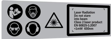
The machine is delivered with a warning label in German language (marked with the number 2 in the representation of the machine on the graphic page). Before putting into operation for the first time, attach the supplied sticker in your national language over the German warning label.
- Never make warning signs on the machine unrecognisable.
- Never stand on the power tool. Serious injuries can occur when the power tool tips over or when inadvertently coming into contact with the saw blade. Make sure that the guard operates properly and that it can move freely. Never lock the guard in place when opened.
- Never remove cutting remainders, wood chips, etc. from the sawing area while the machine is running. Always guide the tool arm back to the neutral position first and then switch the machine off. Guide the saw blade against the workpiece only when the machine is switched on. Otherwise there is damage of kickback, when the saw blade becomes wedged in the workpiece.
- Keep handles dry, clean, and free from oil and grease. Greasy, oily handles are slippery causing loss of control.
Operate the power tool only when the work area to the workpiece is clear of any adjusting tools, wood chips, etc. Small pieces of wood or other objects that come in contact with the rotating saw blade can strike the operator with high speed. Keep the floor free of wood chips and material remainders. You could slip or trip. Always firmly clamp the piece to be worked. Do not saw workpieces that are too small to clamp. Otherwise, the clearance of your hand to the rotating saw blade is too small. Use the machine only for cutting the materials listed under Intended Use. Otherwise, the machine can be subject to overload. If the saw blade should become jammed, switch the machine off and hold the workpiece until the saw blade comes to a complete stop. To prevent kickback, the workpiece may not be moved until after the machine has come to a complete stop. Correct the cause for the jamming of the saw blade before restarting the machine. Do not use dull, cracked, bent or damaged saw blades. Unsharpened or improperly set saw blades produce narrow kerf causing excessive friction, blade binding and kickback. Always use saw blades with correct size and shape (diamond versus round) of arbor holes. Saw blades that do not match the mounting hardware of the saw will run eccentrically, causing loss of control. Do not use high speed steel (HSS) saw blades. Such saw blades can easily break. Do not touch the saw blade after working before it has cooled. The saw blade becomes very hot while working. Never operate the machine without the insert plate. Replace a defective insert plate. Without flawless insert plates, injuries are possible from the saw blade.
- Check the cable regularly and have a damaged cable repaired only through an authorized customer service agent for Bosch power tools. Replace damaged extension cables. This will ensure that the safety of the power tool is maintained.
- Store the machine in a safe manner when not being used. The storage location must be dry and lockable. This prevents the machine from storage damage, and from being operated by untrained persons. Do not direct the laser beam at persons or animals and do not stare into the laser beam yourself, not even from a distance. This power tool produces laser class 2 laser radiation according to EN 60825-1. This can lead to persons being blinded. Do not replace the installed laser with another laser type. A laser that does not fit to this power tool could pose dangers for other persons.
- Secure the workpiece. A workpiece clamped with clamping devices or in a vice is held more secure than by hand.
- Never leave the machine before it has come to a complete stop. Cutting tools that are still running can cause injuries.
- Never use the machine with a damaged cable. Do not touch the damaged cable and pull the mains plug when the cable is damaged while working. Damaged cables increase the risk of an electric shock.
Products sold in GB only: Your product is fitted with a BS 1363/A approved electric plug with internal fuse (ASTA approved to BS 1362).
If the plug is not suitable for your socket outlets, it should be cut off and an appropriate plug fitted in its place by an authorized customer service agent. The replacement plug should have the same fuse rating as the original plug. The severed plug must be disposed of to avoid a possible shock hazard and should never be inserted into a mains socket elsewhere.
Products sold in AUS and NZ only: Use a residual current device (RCD) with a rated residual current of 30 mA or less.
Symbols
The following symbols can be important for the operation of your power tool. Please memorize the symbols and their meanings. The correct interpretation of the symbols helps you operate the power tool better and more securely.
| Symbol | Meaning |
| Wear a dust respirator. |
| Wear safety goggles. |
| Wear ear protectors. Exposure to noise can cause hearing loss. |
| Keep hands away from the cutting area while the machine is running. Danger of injury when coming in contact with the saw blade. |
| Do not direct the laser beam at persons or animals and do not stare into the laser beam yourself, not even from a distance. This power tool produces laser class 2 laser radiation according to EN 60825-1. This can lead to persons being blinded. |
| Observe the dimensions of the saw blade. The hole diameter must match the tool spindle without play. Do not use reducers or adapters. |
| Danger area! Keep hands, fingers or arms away from this area. |
| The transport safety-lock 29 enables easier handling of the machine when transporting to various working locations.
- Transport safety-lock 29 pushed completely inward:
Securing the Machine (Transport Position)
- Transport safety-lock 29 pulled completely outward:
Releasing the Machine (Working Position) |
Symbol
Meaning
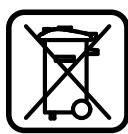
Only for EC countries:
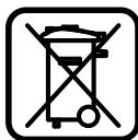
Do not dispose of power tools into household waste! According to the European Guideline 2002/96/EC for Waste Electrical and Electronic Equipment and its implementation into national law, power tools that are no longer usable must be collected separately and disposed of in an environmentally correct manner.
Functional Description

Read all safety warnings and all instructions. Failure to follow the warnings and instructions may result in electric shock, fire and/or serious injury.
Intended Use
The power tool is intended as a stationary machine for making straight lengthways and crossways cuts in wood. In this, miter angles from -47° to +47° as well as bevel angles from 0° to 45° are possible.
The capacity of the power tool is designed for sawing hardwood and softwood.
The power tool is not suitable for cutting aluminum or other non-ferrous metals or alloys.
Product Features
The numbering of the components shown refers to the representation of the power tool on the graphic pages.
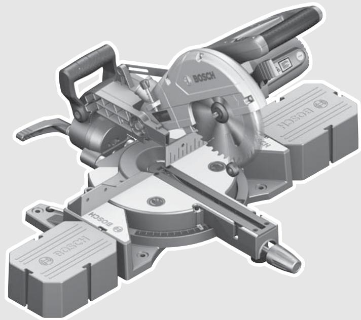
1 Handle 2 Laser warning label 3 Lever for releasing the tool arm 4 Blade guard 5 Retracting blade guard 6 Roller 7 Mounting holes 8 Saw table 9 Locking knob for various metre angles (horizontal) 10 Tilt protector 11 Insert plate
12 Angle indicator (horizontal) 13 Scale for litre angle (horizontal) 14 Saw-Table extension 15 Fence 16 Material clamp 17 Clamping lever for various bevel angles (vertical) 18 Depth stop 19 Dust bag 20 On/Off switch 21 Laser switch (for marking of cutting line) 22 Sawdust ejector 23 Drill holes for material clamp 24 Transport handle 25 Allen key (size 6 mm) 26 Locking screw for slide device 27 Recessed grips 28 Opening for saw-table extension (on saw table base) 29 Transport safety-lock 30 Spindle lock 31 Battery compartment 32 Opening for saw-table extension (on the second saw-table extension) 33 Allen screw (size 6 mm) for mounting of saw blade 34 Clamping flange 35 Interior clamping flange 36 Saw blade 37 Wing bolt 38 Threaded rod 39 Angle indicator (vertical) 40 Scale for bevel angle (vertical)
41 Slide device 42 Casing stop for depth stop 43 Screws for insert plate
Accessories shown or described are not part of the standard delivery scope of the product. A complete overview of accessories can be found in our accessories program.
Technical Data
| Sliding Mitre Saw | PCM 7 S |
| Article number | | 3 603 M01 3.. |
| Rated power input | W | 1200 |
| No-load speed | min-1 | 4800 |
| Laser type | nm | 650 |
| mW | < 1 |
| Laser class | | 2 |
| Weight according to EPTA-Procedure 01/2003 | kg | 11.8 |
| Protection class | | ☐/II |
Permissible workpiece dimensions (maximal/minimal) see page 36.
The values given are valid for a nominal voltage [U] of 230 V. For different voltages and models for specific countries, these values can vary.
Please observe the article number on the type plate of your machine. The trade names of the individual machines may vary.
Dimension of suitable saw blades
| Saw blade diameter | mm | 190 |
| Blade thickness | mm | 1.4–2.5 |
| Mounting hole diameter | mm | 30 |
Measured sound values determined according to EN 61029.
Typically the A-weighted noise levels of the product are: Sound pressure level 94 dB(A); Sound power level 107 dB(A). Uncertainty K = 3 dB.
Wear hearing protection!
Vibration total values (triax vector sum) determined according to EN 61029:
Vibration emission value ah < 2.5 m/s2 , Uncertainty K = 1.5 m/s2 .
The vibration emission level given in this information sheet has been measured in accordance with a standardised test given in EN 61029 and may be used to compare one tool with another. It may be used for a preliminary assessment of exposure.
The declared vibration emission level represents the main applications of the tool. However if the tool is used for different applications, with different accessories or poorly maintained, the vibration emission may differ. This may significantly increase the exposure level over the total working period.
An estimation of the level of exposure to vibration should also take into account the times when the tool is switched off or when it is running but not actually doing the job. This may significantly reduce the exposure level over the total working period.
Identify additional safety measures to protect the operator from the effects of vibration such as: maintain the tool and the accessories, keep the hands warm, organisation of work patterns.
CE
We declare under our sole responsibility that the product described under "Technical Data" is in conformity with the following standards or standardization documents: EN 61029, EN 60825-1 according to the provisions of the directives 2004/108/EC, 2006/42/EC.
Technical file at:
Robert Bosch GmbH, Dept. PT/ESC,
D-70745 Leinfelden-Echterdingen
Dr. Egbert Schneider Senior Vice President Engineering
Dr. Eckerhard Strötgen
Head of Product
Certification
Robert Bosch GmbH, Power Tools Division
D-70745 Leinfelden-Echterdingen
Avoid unintentional starting of the machine. During assembly and for all work on the machine, the power plug must not be connected to the mains supply.
Delivery Scope

Please also observe the representation of the delivery scope at the beginning of the operating instructions.
Before starting the operation of the machine for the first time, check if all parts listed below have been supplied:
- Sliding mitre saw with premounted saw blade, dust bag 19
- Saw-table extension 14 (2x), material clamp 16
- Allen key 25
- Batteries (2x, size LR03, 1.5 V)
Note: Check the power tool for possible damage.
Before further use of the machine, check that all protective devices are fully functional. Any lightly damaged parts must be carefully checked to ensure flawless operation of the tool. All parts must be properly mounted and all conditions fulfilled that ensure faultless operation.
Damaged protective devices and parts must be immediately replaced by an authorized service center.
Mounting Individual Components
- Carefully remove all parts included in the delivery from their packaging.
- Remove all packaging material from the machine and the accessories provided.
- For easier working when mounting the supplied product features, please observe that the machine is in the transport position.
- Open the battery compartment 31.
- Insert the batteries provided according to the specified polarity.
- Close the battery compartment.
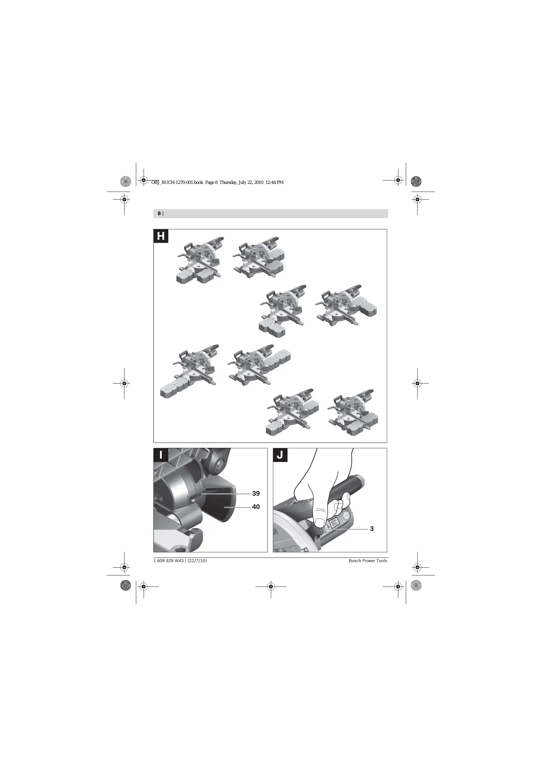
The saw-table extensions 14 can be positioned on the left, right or front of the saw table base. The flexible plug-in system enables a variety of extension possibilities (see figure H).
- Insert the saw-table extension 14 into the openings 28 of the saw-table base or into the openings 32 of the second saw-table extension.
Stationary or Flexible Mounting
To ensure safe handling, the machine must be mounted on a level and stable surface (e.g., workbench) prior to using.
- Screw the tilt protector 10 in or out until the machine is positioned level on the working surface.
- Fasten the power tool with suitable screw fasteners to the working surface. The holes 7 serve for this purpose.
With the height-adjustable legs, Bosch saw stands (e.g. PTA 2400) provide firm support for the power tool on any surface. The workpiece supports of the saw stand are used for underlaying long workpieces.
Note: To support long workpieces in this case, only use the workpiece supports of the saw stand and not the power tool's saw-table extensions 14.
Read all safety warnings and instructions included with the worktable. Failure of observing safety warnings and instructions can lead to electrical shock, fire and/or cause serious injuries.
- Assemble the worktable properly before mounting the power tool. Perfect assembly is important in order to prevent the risk of collapsing. Mount the power tool on the saw stand in the transport position.
Dusts from materials such as lead-containing coatings, some wood types, minerals and metal can be harmful to one's health. Touching or breathing-in the dusts can cause allergic reactions and/or lead to respiratory infections of the user or bystanders.
Certain dusts, such as oak or beech dust, are considered as carcinogenic, especially in connection with wood-treatment additives (chromate, wood preservative). Materials containing asbestos may only be worked by specialists.
Always use dust extraction. - Provide for good ventilation of the working place. - It is recommended to wear a P2 filter-class respirator.
Observe the relevant regulations in your country for the materials to be worked.
The dust/chip extraction can be blocked by dust, chips, or workpiece fragments.
- Switch the machine off and pull the mains plug from the socket outlet.
- Wait until the saw blade has come to a complete stop.
- Determine the cause of the blockage and correct it.
Mount the dust bag 19 onto the sawdust ejector 22.
During sawing, the dust bag must never come into contact with the movable machine parts.
Always empty the dust bag in good time.
For dust extraction, a vacuum hose (size ø36 mm) can also be connected to the dust ejector 22.
The vacuum cleaner must be suitable for the material being worked.
When vacuuming dry dust that is especially detrimental to health or carcinogenic, use a special vacuum cleaner.
Before any work on the machine itself, pull the mains plug. - When mounting the saw blade, wear protective gloves. Danger of injury when touching the saw blade.
Use only saw blades whose maximum permitted speed is higher than the no-load speed of the power tool.
Use only saw blades that correspond with the characteristic data given in these operation instructions and that are tested and marked in accordance with EN 847-1.
Use only saw blades recommended by the tool manufacturer, and suitable for sawing the materials to be cut.
Removing the Saw Blade
Bring the power tool into the working position. - Turn the Allen screw 33 with the Allen key 25 provided while at the same time pressing the spindle lock 30 until it engages. Hold the spindle lock 30 pressed and unscrew the Allen screw 33 in clockwise direction (left-hand thread!). - Remove the clamping flange 34. Press lever 3 and swing back the retracting blade guard 5 to the stop. Hold the retracting blade guard in this position and remove the saw blade 36. - Slowly guide the retracting blade guard downward again.

Mounting the Saw Blade
If required, clean all parts to be mounted prior to assembly.
- Press lever 3, swing back the retracting blade guard 5 to the stop and hold it in this position.
- Place the new saw blade onto the interior clamping flange 35.
- When mounting the saw blade, pay attention that the cutting direction of the teeth (arrow direction on the saw blade) corresponds with the direction of the arrow on the blade guard!
- Slowly guide the retracting blade guard downward again.
- Place on the clamping flange 34 and the screw 33.
Press the spindle lock 30 until it engages and tighten the screw turning in anticlockwise direction.
Operation
Before any work on the machine itself, pull the mains plug.
The transport safety-lock 29 enables easier handling of the machine when transporting to various working locations.
Releasing the Machine (Working Position)
- Push the tool arm by the handle 1 down a little in order to relieve the transport safety-lock 29. Pull the transport safety-lock 29 completely outward.
- Guide the tool arm slowly upward.
Securing the Machine (Transport Position)
- Loosen the locking screw 26 if tightened. Pull the tool arm completely to the front and tighten the locking screw again.
- Screw the depth stop 18 completely to the top. (see "Adjusting the Depth Stop", page 36)
- To lock the saw table 8, tighten the locking knob 9.
- Press lever 3 and at the same time, swing the tool arm by handle 1 toward the rear until the transport safety-lock 29 can be pushed completely inward.
The tool arm is now securely locked for transport.
To ensure optimum working safety, the workpiece must always be firmly clamped.
Do not saw workpieces that are too small to clamp.
- Press the workpiece firmly against the fence 15.
- Insert the material clamp 16 provided into one of the holes 23 intended for it.
- Loosen the wing bolt 37 and adapt the material clamp to the workpiece. Tighten the wing bolt again.
- Firmly clamp the workpiece by turning the threaded rod 38 in clockwise direction.
Loosening the Workpiece
- To release the material clamp, turn the threaded rod 38 in anticlockwise direction.
Long workpieces must be underlaid or supported at their free end.
The flexible saw-table extension plug-in system 14 enables a variety of extension possibilities.
- Insert the saw-table extension 14 into the openings 28 of the saw-table base or into the openings 32 of the second saw-table extension.
Adjusting the Cutting Angle
- When adjusting the cutting angle, never actuate the On/Off switch 20. Danger of injury if the machine should accidentally start.
Adjusting Horizontal Mitre Angles
The horizontal mitre angle can be set in the range from 47° (left side) to 47° (right side).
- Loosen the locking knob 9 in case it is tightened.
- Turn the saw table 8 left or right by the locking knob until the angle indicator 12 indicates the requested metre angle.
- Tighten the locking knob 9 again.
For quick and precise setting of often used miter angles, the saw table 8 engages at the detents of the following standard angles:
-45° / -30° / -22.5° / -15° / 0° / 15° / 22.5° / 30° / 45°
The vertical bevel angle can be set in the range from 0° to 45°.
- Loosen the clamping lever 17.
- Tilt the tool arm by the handle 1 until the angle indicator 39 indicates the desired bevel angle. Hold the tool arm in this position and retighten the clamping lever 17.
For quick and precise setting of the standard angles 0° and 45°, end stops are provided on the housing.
- Loosen the clamping lever 17.
- For this, tilt the tool arm by the handle 1 to the stop toward the right (0°) or to the stop toward the left (45°).
- Retighten the clamping lever 17 again.
Starting Operation
Observe correct mains voltage! The voltage of the power source must agree with the voltage specified on the nameplate of the machine. Power tools marked with 230V can also be operated with 220V.
- To start the machine, press the On/Off switch 20 and keep it pressed.
Note: For safety reasons, the On/Off switch 20 cannot be locked; it must remain pressed during the entire operation.
The tool arm can only be guided downward when pressing lever 3.
- For sawing, you must additionally press lever 3 in addition to actuating the On/Off switch 20.
Switching Off
- To switch off the machine, release the On/Off switch 20.
Working Advice
General Sawing Instructions
Always firmly tighten locking knob 9 and clamping lever 17 before sawing. Otherwise the saw blade could become jammed in the workpiece. For all cuts, it must first be ensured that the saw blade at no time can come in contact with the fence, screw clamps or other machine parts. Remove possibly mounted auxiliary stops or adjust them accordingly.
Protect the saw blade against impact and shock. Do not subject the saw blade to lateral pressure.
Do not saw warped/bent workpieces. The workpiece must always have a straight edge to face against the fence.
Long workpieces must be underlaid or supported at their free end.
A laser beam indicates the cutting line of the saw blade. This allows for exact positioning of the workpiece for sawing, without having to open the retracting blade guard.
- For this, switch the laser beam on with the switch 21.
- Align the cutting mark on your workpiece with reference to the right-hand edge of the laser line.



Do not stand in a line with the saw blade in front of the machine. Always stand aside of the saw blade. This protects your body against possible kickback. - Keep hands, fingers and arms away from the rotating saw blade. - Do not cross your arms when operating the tool arm.
Permissible Workpiece Dimensions
Maximal workpiece sizes:
| Mitre/Bevel Angle | Height x Width |
| Horizontal | Vertical | |
| 0° | 0° | 40 x 220 mm |
| 45° | 0° | 40 x 150 mm |
| 0° | 45° | 18 x 220 mm |
| 45° | 45° | 18 x 150 mm |
Minimal workpiece sizes
(= all workpieces that can be clamped left or right from the saw blade with the supplied material clamp 16):
100 × 40 mm (length x width)
Cutting capacity, max. (0° / 0°) .. 40 mm
- For cuts without slide movement (small workpieces), loosen the locking screw 26 in case it is tightened. Slide the tool arm to the stop in the direction of the fence 15 and retighten the locking screw 26.
- Firmly clamp the workpiece as appropriate for its dimensions.
- Set the desired mitre angle.
- Switch on the machine.
- Press lever 3 and slowly guide the tool arm downward by handle 1.
- Saw through the workpiece applying uniform feed.
- Switch off the machine and wait until the saw blade has come to a complete stop.
- Guide the tool arm slowly upward.
Sawing with Slide Movement
- For cuts using the slide device 41 (wide workpieces), loosen the locking screw 26 in case it is tightened.
- Firmly clamp the workpiece as appropriate for its dimensions.
- Set the desired mitre angle. Pull the tool arm away from the fence 15 far enough so that the saw blade is in front of the workpiece.
- Switch on the machine.
- Press lever 3 and slowly guide the tool arm downward by handle 1.
- Press the tool arm in the direction of the fence 15 and saw through the workpiece applying uniform feed.
- Switch off the machine and wait until the saw blade has come to a complete stop.
- Guide the tool arm slowly upward.
The depth stop must be adjusted when a butt gap is to be sawed.
- Tilt the tool arm by the handle 1 to the position at which the requested groove depth is reached.
- Screw depth stop 18 in clockwise direction until the screw end faces against casing stop 42.
- Guide the tool arm slowly upward.
The red insert plate 11 can become worn after long use of the power tool.
Replace defective insert plates.
Bring the power tool into the working position. - Unscrew screws 43 using a Phillips screwdriver and remove the old insert plate. - Insert the new insert plate and screw all screws 43 in again.
Sawing Profile Strips
Profile strips/mouldings can be sawn in two different ways:
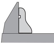
Lying flat on the saw table
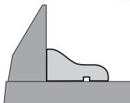
In addition, the cut can be performed with or without slide movement depending on the width of the profile strip/moulding.
Always make trial cuts with the litre angle setting first on scrap wood.
Before transporting the power tool, the following steps must be carried out:
Bring the machine into the transport position. - Insert the saw-table extensions 14 into the power tool's front openings 28. - Remove all accessories that cannot be mounted firmly to the power tool. If possible, place unused saw blades in an enclosed container for transport. - Carry the machine by the transport handle 24 or hold it by the recessed grips 27 on the sides of the saw table. - When transporting the power tool, use only the transport devices and never use the protective devices.
Maintenance and Service
Maintenance and Cleaning
Before any work on the machine itself, pull the mains plug.
If the machine should fail despite the care taken in manufacturing and testing procedures, repair should be carried out by an after-sales service centre for Bosch power tools.
In all correspondence and spare parts order, please always include the 10-digit article number given on the type plate of the machine.
Cleaning
For safe and proper working, always keep the power tool and its ventilation slots clean.
The retracting blade guard must always be able to move freely and retract automatically. Therefore, always keep the area around the retracting blade guard clean.
Remove dust and chips after each working procedure by blowing out with compressed air or with a brush.
Clean the roller 6 regularly.
Accessories
Saw blades for wood and plate materials, panels and strips/mouldings
Saw blade 190 × 30 mm ,
40 teeth 2609 256 821
Saw blade 190 × 30 mm
12 teeth 2609 256 868
Saw blade 190 × 30 mm
24 teeth 2608640615
Saw blade 190 × 30 mm
60 teeth 2 608 641 188



After-sales Service and Customer Assistance
Our after-sales service responds to your questions concerning maintenance and repair of your product as well as spare parts. Exploded views and information on spare parts can also be found under:
www.bosch-pt.com
Our customer service representatives can answer your questions concerning possible applications and adjustment of products and accessories.
Great Britain
Robert Bosch Ltd. (B.S.C.)
P.O.Box 98
Broadwater Park
North Orbital Road
Denham
Uxbridge
UB 95HJ
Tel. Service: +44 (0844) 736 0109
Fax: +44 (0844) 736 0146
E-Mail: boschservicecentre@bosch.com
Ireland
Origo Ltd.
Unit 23 Magna Drive
Magna Business Park
City West
Dublin 24
Tel. Service: +353 (01) 466 67 00
Fax: +353 (01) 466 68 88
Australia, New Zealand and Pacific Islands
Robert Bosch Australia Pty. Ltd.
Power Tools
Locked Bag 66
Clayton South VIC 3169
Customer Contact Center
Inside Australia:
Phone: +61 (01300) 307 044
Fax: +61 (01300) 307 045
Inside New Zealand:
Phone: +64 (0800) 543 353
Fax: +64 (0800) 428 570
Outside AU and NZ:
Phone: +61 (03) 9541 5555
www.bosch.com.au
Republic of South Africa
Customer service
Hotline: +27 (011) 6519600
Gauteng - BSC Service Centre
35 Roper Street, New Centre
Johannesburg
Tel.: +27 (011) 493 93 75
Fax: +27 (011) 493 01 26
E-Mail: bsctools@icon.co.za
KZN - BSC Service Centre
Unit E, Almar Centre
143 Crompton Street
Pinetown
Tel.: +27 (031) 7 01 21 20
Fax: +27 (031) 701 2446
E-Mail: bsc.dur@za.bosch.com
Western Cape - BSC Service Centre
Democracy Way, Prosperity Park
Milnerton
Tel.: +27 (021) 5512577
Fax: +27 (021) 5513223
E-Mail: bsc@zsd.co.za
Bosch Headquarters
Midrand, Gauteng
Tel.: +27 (011) 6519600
Fax: +27 (011) 6519880
E-Mail: rbsa-hq.pts@za.bosch.com
Disposal
The machine, accessories and packaging should be sorted for environmental-friendly recycling.
Do not dispose of power tools into household waste!
Only for EC countries:
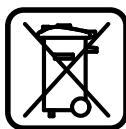
According to the European Guideline 2002/96/EC for Waste Electrical and Electronic Equipment and its implementation into national law, power tools that are no longer usable must be collected
separately and disposed of in an environmentally correct manner.
Subject to change without notice.


Robert Bosch GmbH, Dept. PT/ESC,
D-70745 Leinfelden-Echterdingen
Dr. Egbert Schneider Senior Vice President Engineering
Dr. Eckerhard Strötgen Head of Product
Certification
Robert Bosch (France) S.A.S.
Robert Bosch GmbH, Dept. PT/ESC,
D-70745 Leinfelden-Echterdingen
Dr. Egbert Schneider
Dr. Eckerhard Strötgen
Senior Vice President
Head of Product
Engineering
Certification
ppa. Maee i.v. Nooey
Robert Bosch GmbH, Power Tools Division
D-70745 Leinfelden-Echterdingen
Dr. Egbert Schneider Senior Vice President Engineering
Dr. Eckerhard Strötgen Head of Product Certification
ppa. Maee i.v. Nooey
Robert Bosch GmbH, Power Tools Division D-70745 Leinfelden-Echterdingen Leinfelden, 22.07.2010
Montagem
Robert Bosch GmbH, Dept. PT/ESC,
D-70745 Leinfelden-Echterdingen

Dr. Egbert Schneider Senior Vice President Engineering
Dr. Eckerhard Strötgen Head of Product Certification
ppa. Maee i.v. Nogcu
Robert Bosch GmbH, Power Tools Division D-70745 Leinfelden-Echterdingen Leinfelden, 22.07.2010
Montaggio
Notabene: In Anything to be done, I will do it. Notea bene: In what is to be done, I will do it.
Dr. Egbert Schneider Dr. Eckerhard Ströttgen Senior Vice President Head of Product Engineering Certification
Stationaire of flexible montage
Dr. Egbert Schneider Dr. Eckerhard Ströttgen Senior Vice President Head of Product Engineering Certification

Robert Bosch GmbH, Power Tools Division D-70745 Leinfelden-Echterdingen Leinfelden, 22.07.2010
Montering
Transport (see Fig. P)
Before transporting the power tool, perform the following steps:
- Set the power tool to the transport position.
- Insert the saw table extensions 14 into the front holders 28 on the power tool.
- Remove all accessory parts that cannot be securely mounted on the power tool.
Saw blades not in use should preferably be stored in a closed container when transported.
Carry the power tool by the transport handle 24 or grip the recesses 27 on the sides of the saw table.
Bosch Service Center
Telegrafvej 3
2750 Ballerup
Tel. Service Center: +45 (4489) 8855
Fax: +45 (4489) 87 55
E-Mail: vaerktoej@dk.bosch.com
Disposal
Dr. Egbert Schneider Senior Vice President Engineering
Dr. Eckerhard Strötgen Head of Product Certification
ppa. Maee i.v. Nooey
Robert Bosch GmbH, Power Tools Division D-70745 Leinfelden-Echterdingen Leinfelden, 22.07.2010
Assembly
Bosch Service Center
Telegrafvej 3
2750 Ballerup
Denmark
Tel.: +46 (020) 41 44 55
Fax: +46 (011) 187691
Waste disposal
Only for EU countries:
Robert Bosch GmbH, Dept. PT/ESC,
D-70745 Leinfelden-Echterdingen
Dr. Egbert Schneider Senior Vice President Engineering
Dr. Eckerhard Strötgen Head of Product Certification
ppa. Maee i.v. Nogcu
Robert Bosch GmbH, Power Tools Division
D-70745 Leinfelden-Echterdingen
Dr. Egbert Schneider Senior Vice President Engineering
Dr. Eckerhard Strötgen Head of Product Certification
ppa. Maee i.v. Nogcu
Robert Bosch GmbH, Power Tools Division D-70745 Leinfelden-Echterdingen Leinfelden, 22.07.2010
Assembly
Dr. Egbert Schneider Senior Vice President Engineering
Dr. Eckerhard Strötgen Head of Product Certification
ppa. Maee i.v. Nogcu
Robert Bosch GmbH, Power Tools Division D-70745 Leinfelden-Echterdingen Leinfelden, 22.07.2010
Sigma
Read all safety warnings and all instructions for the power tool. Failure to follow the warnings and instructions may result in electric shock, fire and/or serious injury.
We reserve the right to make changes.
Safety Instructions
General Power Tool Safety Warnings

WARNING
When using power tools, to avoid electric shock,
Dr. Egbert Schneider Senior Vice President Engineering
Dr. Eckerhard Strötgen Head of Product Certification
ppa. Maee i.v. Nooey
Robert Bosch GmbH, Power Tools Division D-70745 Leinfelden-Echterdingen Leinfelden, 22.07.2010
Assembly
Robert Bosch GmbH, Dept. PT/ESC,
D-70745 Leinfelden-Echterdingen
Dr. Egbert Schneider Senior Vice President Engineering
Dr. Eckerhard Strötgen Head of Product
Certification
Robert Bosch Sp. z o.o.
Dr. Egbert Schneider Senior Vice President Engineering
Dr. Eckerhard Strötgen Head of Product Certification
ppa. Maee i.v. Nogcu
Robert Bosch GmbH, Power Tools Division D-70745 Leinfelden-Echterdingen Leinfelden, 22.07.2010
Assembly
Bosch Service Center PT
K Vapence 1621/16
692 01 Mikulov
Tel.: +420 (519) 305 700
Fax: +420 (519) 305 705
E-Mail: servis.naradi@cz.bosch.com
www.bosch.cz
Waste disposal
Dr. Egbert Schneider Senior Vice President Engineering
Dr. Eckerhard Strötgen Head of Product Certification

Robert Bosch GmbH, Power Tools Division D-70745 Leinfelden-Echterdingen Leinfelden, 22.07.2010
Assembly
Robert Bosch GmbH, Dept. PT/ESC,
D-70745 Leinfelden-Echterdingen
238 | Magyar
Dr. Egbert Schneider Senior Vice President Engineering
Dr. Eckerhard Strötgen Head of Product Certification
ppa. Maee i.v. Nogcu
Robert Bosch GmbH, Power Tools Division D-70745 Leinfelden-Echterdingen Leinfelden, 22.07.2010
Assembly
Only for EU countries:
Do not dispose of power tools and batteries in household waste! According to the European Directive 2002/96/EC on waste electrical and electronic equipment and its implementation in national law, power tools that have reached the end of their service life must be collected separately and returned to an environmentally compatible recycling facility.
Function description

Safety instructions. All instructions and safety information must be read and followed. Failure to follow the instructions and safety information may result in electric shock, fire, and/or serious injury.
Intended use
The power tool is intended for cutting and sawing wood, when mounted on a base. It allows horizontal cutting angles from -47° to +47° and vertical cutting angles from 0° to 45°.
The power of the power tool is designed for cutting hard and soft wood.
3AleKtpOnHCTpymEt H Te pInrOaEn dApaacnHbAHnna aHOMHHnN n Dpynx CBeTHbIXMeTaMOB.
H3o6paXeHHbIe coCTaBbIe qactn
Hymepaunca coctabhix xacte BblnoHa hno 1306paqehnHO h CTpaHnCe C HnIOCTpaunmN.
1 PykorTka 2IpeDyIpeDnteHna Ta6nUka Ia3epHoro n3AyuHn 3 Pbyar dA OcAa6AeHn KpOHTeHa 4 3aunThbIKoKoxyX 5 MaTHNKOBbI 3aUHTbI KOKyx 6 PoAnk CKoAxbxehnA
7 OTBepCTnA DAn KpeTnEHHN 8 CToA TnAbi 9 PyuKaФнКсИрOBaHЯ ПрОиЗВоЛьНOrOуглapacnIa(ropIN3OHTaBHOrO)
10 PpeoXpaHHTeIb OT OpiPOKnIbBaHnI 11ПANTa-BKlaablw 12 Yka3aTeIb yIa pacTnIIa (rOpN3OHTaIbHOrO) 13 Ⅲkaλa yrla paacnla (rOpH0HTaBbHorO) 14 YdHnHTeA b cTOna 15 YnpnHaI nnAHaKa 16 Ctpy6uHa 17 3axmna pyka dAII pOIN3BObHOro yra pacTnla (BepTKaIbHoro) 18 OrpaHnHTeIb Iy6HbI 19ПыевМшOK 20 BbiklouaTeA 21 BbikouateIb Ia3epa (o603haueHne IHHn paacnna) 22 Ptp6ok dAy BbIbpoca OtnloK 23 OTBepctnA DAA CTpy6uH 24 Puyka dIa Iepenocn 25 KaHou-WeCTnIgpaHHNK (6 MM) 26 BnHT qHKcnpoBaHnTAROBOr yCTpoIcTb 27 YrIy6IeHHa 3aXBaTa 28 KpeIeHne IaYdHnHTeA CToIa (Ha 3eKtponHCTpymente) 29 TpaHcTOpTHbI IpeOxpaHnTeIb 30 ΦнксаTopшпндeя 31 Otcek dAЯ 6aTapei 32 KpeIeHne Iy dIyHHTeA CTOla (Ha pyrom ydIyHHTeAe CTOla) 33 BnHT C BHyTpEHHM WcetHrpAHHNKOM (6 MM) DЯ KpeTaeHn TINbHOrO dNcKa
252 | Pycckn
34ПпнЖИМНофlaHeu 35 BHyTpEHHN 3aXHMHOJ φ aHeu 36 ΠιαλβΗβίν ἀνχό 37БарашКOBынВИNT 38 BnHT CTpy6uHbI 39 Yka3aTeIb yIa pacTHnla (BepTKKaIbHorO) 40 Lkaa yra paacnna (BepTKKaIbHorO) 41 TaroBoe yctpoNCTBO 42 Otnopa dA ynpa rHy6nHbI 43 BnHTbI TAnTbI-BKλaDbIwa
H3o6paXeHHbI HnOtncaHHbI pInHaAExKHOCTn He BXoADT B cTaHApTbH bObE mIOCTaBKn. IToAHbI accOPTHMENT pInHaAExKHOCTe Bbl HaJeTe B hAwei Iporpamme pInHaAExKHOCTe.
TexHnueckne daHHbIe
YpOBeHb Bn6paunu yka3aH DAA OCHOBhix BnIOB pa6oTbI c 3AeKTPoHHCTpyMeHTOM. ODAHO ECAN 3AeKTPoHHCTpyMeHT 6yDet NCTIOABoAH DAA BblIOHaHeHna Dpyrnx pa6OT C pPIMHeHneM pa6OuHX INCTpyMeHTOB, He IpeDyCMOTpeHHbIX n3rTOBNTeLEM, HN TeXHnueckoe o6- C LyxKnBaHne He 6yDet OTBeuAtb PpeDnHcAHNR, To ypOBeHb Bn6paunu MoKeT 6bITb HbIM. 3To MOKeT 3HaUHTeBHO IOBbICHTb Bn6paUNOHHyHO Harpy3kY B TceHHe BCEI PPODOJXHTeBHOCTn pa6oTbI.
Ara ToHOn OueHKn Bn6paunOHn Harpy3Kn B TeueHne OnpedeAeHHoro BpeMeHHoro INHePbAa HyXHo yuHTbIbTa TaKxe I BpEm, KOrda IHCTpyMeHT BblKIOUeH NAn, XOTN BkIOUeH, HO He HaxoDNTcB pa6Ote. 3To MoKet 3HaunTeAbHo COKpaTbHarpy3Ky OT Bn6paUNB paucTe Ha TIOHoe pa6Ouee BpEm.
IpeycmOTpHTe DOIOHHTeBHBie Mepbl 6e3- ONaCHOCTN AaUNTbOtepaTopo OT Bo3eInCT

BnBn6paun,HaIprImep:TexHnueckoe 06cLyKnBaHne 3eKtpOnHCTpyMeNTa n pa6oynx H-CTpyMeHTOB,MepbI IIO IOaepXaHNIO pyK BTePLe,oprAHH3aun TeXHOIoRHeCKNX PpoceCCOB.
3aBHeHne o COOTBeTCTBHN C
The manufacturer declares that the products described in the "Technical Data" comply with the following standards and normative documents: EN 61029, EN 60825-1 in accordance with the provisions of Directives 2004/108/EC and 2006/42/EC.
Technical documentation: Robert Bosch GmbH, Dept. PT/ESC, D-70745 Leinfelden-Echterdingen
Dr. Egbert Schneider Dr. Eckerhard Ströttgen Senior Vice President Head of Product Engineering Certification
Press the switch lock 19 onto the hose for the extraction outlet 22.
During operation, the tool must not come into contact with moving parts of the machine.
Empty the dust bag in a timely manner.
External dust extraction
The extraction hose for outlet 22 can be connected to a vacuum cleaner (36 mm).
The hose must be suitable for the material being processed.
Use special extraction hoses for dusts that are hazardous to health, carcinogenic, or dry dust.
Replacing the tool (see figures E1-E4)
Before any work on the machine, pull the plug out of the socket. When installing the saw blade, wear protective gloves. Risk of injury when touching the saw blade.
Use only saw blades with a maximum permissible speed higher than the no-load speed of your power tool.
Use only saw blades with the diameter specified in this manual, which have been tested according to EN 847-1 and bear the corresponding marking.
Use only saw blades recommended by the manufacturer of the power tool and suitable for the material being processed.
Dust extraction disc
Place the tool in the working position. Turn the inner hexagon with the 33 mm wrench and simultaneously press the spindle lock 30 so that it engages. Press the spindle lock 30 and simultaneously turn the screw 33 counterclockwise (left-hand thread!). - Remove the clamping flange 34. Press the lever 3 and fold the pendulum protective guard 5 back as far as it will go. - Hold the pendulum protective guard in this position and remove the dust extraction disc 36. - Slowly fold the pendulum protective guard back.
Mounting the dust extraction disc
To ensure maximum safety at work, always secure the workpiece. Do not process workpieces that are too small to be secured.
Application instructions
General application instructions
Before starting work, always firmly tighten the adjusting handle 9 and the clamping handle 17. Otherwise, the dust extraction disc may tilt in the workpiece. Regardless of the application, you must first check the possibility of the dust extraction disc coming into contact with the stop plate, clamps, or other parts of the tool. Remove any possible auxiliary stops or adjust them accordingly.
Protect the dust extraction disc from impacts and shocks. Do not press on the side of the dust extraction disc. Do not process warped workpieces. The workpiece must always have a straight edge for guiding against the stop plate. The free end of long workpieces must rest on a support.
Marking the cutting line (see Fig. K)
The laser beam shows the cutting line of the dust extraction disc. This allows you to position the workpiece to be cut precisely without opening the pendulum protective guard.
- Switch on the laser beam using switch 21. Align the marking on the workpiece with the right edge of the laser line.
Operator position (see Fig. L)
Do not stand in front of the power tool in line with the dust extraction disc; always stand to the side in a staggered position relative to the dust extraction disc. This way you can protect yourself from possible kickback. Do not place your hands or fingers near the rotating dust extraction disc.
- Do not reach over the tool with your hands while it is running.
Workpiece dimensions
Machinable blanks:
| Угол pасима
Горион-
Тальный | Верн-
Кальный | Бысota x
ШирINA |
| 0° | 0° | 40 x 220 MM |
| 45° | 0° | 40 x 150 MM |
| 0° | 45° | 18 x 220 MM |
| 45° | 45° | 18 x 150 MM |
Minimum blanks: (= all blanks that can be clamped to the left or right of the main disc using the clamping device 16):
Carry spare discs that you do not use, if possible in closed containers.
Carry electronic tools, take hold of the transport handles, never use protective devices for these purposes. ▸ Carry electronic tools, take hold of the transport handles, never use protective devices for these purposes.
Maintenance and service
Maintenance and cleaning
Before any maintenance, pull the plug out of the socket.
If the electronic tool, despite careful manufacturing and testing, fails, repair should be carried out by an authorized service workshop for electronic tools directly.
Please, in all inquiries and orders for spare parts, always indicate the 10-digit item number according to the manufacturer's plate of the electronic tool.
Cleaning
To ensure quality and safe work, keep the electronic tool and ventilation slots clean.
The protective hood must always be able to move freely and close automatically. Therefore, always keep the area around the protective hood clean.
After each work step, remove dust and chips with a stream of compressed air or a brush.
Regularly clean the suction hose.
Accessories
Types of discs for various materials, such as cutting and grinding
Cutting disc 190 x 30 mm, 40 teeth. 2 609 256 821
Cutting disc 190 x 30 mm, 12 teeth. 2 609 256 868
Cutting disc 190 x 30 mm, 24 teeth. 2 608 640 615
Cutting disc 190 x 30 mm, 60 teeth. 2 608 641 188


Service and customer consultation
The service department will answer all your questions regarding repair and maintenance of your product, as well as spare parts. Exploded views and information on spare parts can also be found at:
The Bosch consulting team will be happy to assist you with questions about purchasing, application, and adjustment of products and accessories.
Region: Russia, Belarus, Kazakhstan
Warranty service and repair of power tools, in compliance with the standards of the manufacturer, are carried out in all countries only at authorized or certified service centers of "Robert Bosch".
WARNING! Use of counterfeit products is dangerous and may cause harm to your health. Manufacturing and distribution of counterfeit products is prosecuted by law in administrative and criminal proceedings.
Russia
LLC "Robert Bosch"
Service center for power tool maintenance
JSC Akademika Koroleva, str. 13/5 129515, Moscow
Russia
Tel.: +7 (800) 100 8007
E-Mail: pt-service@ru.bosch.com
You can get full information about the location of service centers on the official website www.bosch-pt.ru or by calling the Bosch information and service hotline 8-800-100-8007 (toll-free call).
Belarus
Robert Bosch LLC
Service center for power tools
ul. Timiryazeva, 65A-020
220035, Minsk
Belarus
Tel.: +375 (17) 254 78 71
Tel.: +375 (17) 254 79 15/16
Fax: +375 (17) 254 78 75
Fax: +375 (17) 254 78 75
E-Mail: pt-service@by.bosch.com
Official website: www.bosch-pt.by
Kazakhstan
LLC "Robert Bosch"
Service center for power tools
Electrical tools
51 Seifullin St.
050037 Almaty
Kazakhstan
Tel.: +7 (727) 2323707
Fax: +7 (727) 251 13 36
E-Mail: pt-service@kz.bosch.com
Do not dispose of power tools in household waste!
According to the EU Directive 2002/96/EC on waste electrical and electronic equipment
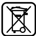
According to the European Directive 2002/96/EC on waste electrical and electronic equipment
MeHTax I pIb6opax I
aadeKBaTHOMy IIpeIINcaHIO HaunHOHaIbHOro IpaBa,OT-
ClyxNBnCe CBOIp CPOK 3eKtpOnHCTpyMeHTbl D0AkhBbOTDeAebHO Co6HpTaBCaCdaBaTbcHa 3KOLOrHueckn YNCTyIO yTNNAuIO.
Bo3MOxHbI n3MeHeHHa.
ME77


Bka3iBkn 3 Texhikn 6e3neKn
3araIbHi 3aCTepeXeHHA DAA eAleKtpoPpHaaDIB

YBATA
Aa3axncty BiD ypaXeHHN
eAektpnHm Ctpymom, TpaBM Ta
TIOKEXI IID ac po6Otn 3 eAEKtpoiHCTpymeHTAMn Tpe6a 3BaXaTn Ha IIpnHcNIOBI IIpaBnla 3 texhIKn 6e3neKn.
Ipepe ekctnyatauicio ealektpoiHcTpymenty npouHTaTe Bci Bka3iBKn 3Texhikn 6e3neKn i do6pe 36epexitb ix.
ПД ПОНТТМ «eLEKTOIHCTPymeHT》,Ю
ВИКОРСТОВЕТСА ВКAZIBKAX 3 TEXHIKN
6e3IeKN,MaTbCSHa YBa3i eLEKTOIHCTPymeHT,
IIO IPIaIIOE BiD Мерекi (i3 IHHypOM KINBAEHHN)
a6O BiD aKymyIaTOPHOI 6aTapei (6e3 IHHpa
KINBAEHHN).
1) Be3πεka ha po6ouomy micui
a) TpmaTe CBOe po6oue Micu B uHCToti i 3a6e3neUte O6pe oCBiAenHa po6oOro Micua. Be3laA a6o IoraHe oCBiTaeHHa H apo6oOmy Micui MoKyTb Pn3BecTH Do HeuacnX BnTaKIB. 6) He npaioiTe 3 eAleKToPpHnAdom y cepeoBnui, de icHye He6e3neKa Bn6bxyu BhaCIAO kIpcSyTHOCTi rOpouxPiHN, ra3iB a60 nMy. EaleKToPpHnAan MoKyTB IporoJyBaTH ickpn, BiAЯknx MoKe 3aMmTaSC PnA a60 napn. B)ПiДчacпраci 3 ealeKTPoTPnlaaOM He PIIpyckaiTe Do pOboovoro Micra DiTe Ta iHuxIIOde. Bn MoXeTe BtpaHTn KOHTPOb NaD TrpnaAdom,Якso BaSha yBara 6yde BiDBepHyta.
2) Electrical safety
a) The plug must fit into the outlet. Do not modify the plug in any way. Do not use any adapter plugs with earthed (grounded) power tools. Unmodified plugs and matching outlets will reduce risk of electric shock.
b) Avoid body contact with earthed or grounded surfaces, such as pipes, radiators, ranges and refrigerators. There is an increased risk of electric shock if your body is earthed or grounded. c) Protect the tool from rain and moisture. Water entering a power tool will increase the risk of electric shock. d) Do not abuse the cord. Never use the cord for carrying, pulling or unplugging the power tool. Keep cord away from heat, oil, sharp edges or moving parts. Damaged or entangled cords increase the risk of electric shock. e) When operating a power tool outdoors, use an extension cord suitable for outdoor use. Use of a cord suitable for outdoor use reduces the risk of electric shock. f) If operating a power tool in a damp location is unavoidable, use a residual current device (RCD) protected supply. Use of an RCD reduces the risk of electric shock.
3) Personal safety
a) Stay alert, watch what you are doing and use common sense when operating a power tool. Do not use a power tool while you are tired or under the influence of drugs, alcohol or medication. A moment of inattention while operating power tools may result in serious personal injury. b) Use personal protective equipment. Always wear eye protection. Protective equipment such as dust mask, non-skid safety shoes, hard hat, or hearing protection used for appropriate conditions will reduce personal injuries.
c) Prevent unintentional starting. Ensure the switch is in the off-position before connecting to power source and/or battery pack, picking up or carrying the tool. Carrying power tools with your finger on the switch or energising power tools that have the switch on invites accidents. d) Remove any adjusting key or wrench before turning the power tool on. A wrench or a key left attached to a rotating part of the power tool may result in personal injury. e) Do not overreach. Keep proper footing and balance at all times. This enables better control of the power tool in unexpected situations. f) Dress properly. Do not wear loose clothing or jewellery. Keep your hair, clothing and gloves away from moving parts. Loose clothes, jewellery or long hair can be caught in moving parts. g) If devices are provided for the connection of dust extraction and collection facilities, ensure these are connected and properly used. Use of dust collection can reduce dust-related hazards.
B) When using the power tool, keep the power cord away from the power source or battery. Do not carry the tool by the cord or move it while the cord is plugged in. Keep the cord away from heat, oil, sharp edges, or moving parts. Damaged or entangled cords increase the risk of electric shock. C) When operating a power tool outdoors, use an extension cord suitable for outdoor use. Use of a cord suitable for outdoor use reduces the risk of electric shock. D) If operating the power tool in a damp location is unavoidable, use a residual current device (RCD) protected supply. Use of an RCD reduces the risk of electric shock. E) Stay alert, watch what you are doing, and use common sense when operating a power tool. Do not use a power tool while you are tired or under the influence of drugs, alcohol, or medication. A moment of inattention while operating power tools may result in serious personal injury. F) Use personal protective equipment. Always wear eye protection. Protective equipment such as dust mask, non-skid safety shoes, hard hat, or hearing protection used for appropriate conditions will reduce personal injuries. G) Prevent unintentional starting. Ensure the switch is in the off-position before connecting to power source, picking up or carrying the tool. Carrying power tools with your finger on the switch or energizing power tools that have the switch on invites accidents. H) Remove any adjusting key or wrench before turning the power tool on. A wrench or a key left attached to a rotating part of the power tool may result in personal injury. I) Do not overreach. Keep proper footing and balance at all times. This enables better control of the power tool in unexpected situations. J) Dress properly. Do not wear loose clothing or jewelry. Keep your hair, clothing, and gloves away from moving parts. Loose clothes, jewelry, or long hair can be caught in moving parts. K) If devices are provided for the connection of dust extraction and collection facilities, ensure these are connected and properly used. Use of dust collection can reduce dust-related hazards.
Components shown
The image of the components is shown in the figure on the pages with the small numbers.
1 Handle 2 Corrected table for working with a laser 3 Release button for the working tool 4 Protective cover 5 Magnetic protective cover 6 Roller guide 7 Mounting holes 8 Saw 9 Handle for adjusting the saw to the horizontal position and tilting (horizontal) 10 Protection against kickback 11 Insert 12 Angle indicator (horizontal) 13 Adjustment and tilting device (horizontal) 14 Saw blade
15 Support plate 16 Clamp 17 Locking handle for vertical angle adjustment (vertical) 18 Limit stop 19 Blade for saw 20 Switch 21 Laser switch (for marking the cutting line) 22 Switch for laser 23 Opening for clamp 24 Transport handle 25 Hex key (6 mm) 26 Fixing screw for the guide device 27 Rear handle 28 Attachment for the support plate (on the electric tool) 29 Transport lock 30 Fixing screw 31 Battery compartment 32 Attachment for the support plate (on another support plate) 33 Pin with internal hexagon (6 mm) for attaching the saw blade 34 Locking flange 35 Internal locking flange 36 Saw blade 37 Wing bolt 38 Threaded rod 39 Angle indicator (vertical) 40 Vertical adjustment knobs 41 Tensioning device 42 Control on the housing and limit stop 43 Screws for the insert
The image or the accessories are not included in the standard delivery. The complete range of accessories can be found in our accessories program.
Technical data
Dr. Egbert Schneider Senior Vice President Engineering
Dr. Eckerhard Strötgen Head of Product Certification
Please observe the safety instructions for the disposal of materials.
The dust extraction device/hose can become clogged with dust, chips, or workpieces.
Switch off the electric tool and pull the plug out of the socket. Wait until the tool has come to a complete stop. Check the cause of the clogging and remove it.
Dust extraction system (see figure C)
Fill the dust bag 19 and attach it to the laser switch 22.
When tilting the saw, the dust bag must not be in the way of the moving parts of the tool.
Always empty the dust bag in a timely manner.
External dust extraction
All instructions for use must be read before operating the machine (036MM)22.
The operator must be trained to work with the material being processed.
For sanding, only use the appropriate type of abrasive, whether belt or disc type.
Replacing the working tool (see Fig. E1-E4)
Before any work, disconnect the power plug from the socket. During assembly of the sanding disc, it is mandatory to wear protective gloves. Touching the sanding disc poses a risk of injury.
Use only sanding discs whose maximum speed is higher than the speed of the power tool at idle.
Use only sanding discs that meet the specifications given in the instructions, comply with EN 847-1, and have complete markings.



Use only sanding discs recommended by the power tool manufacturer and suitable for the material being processed.
Removing the sanding disc
Set the power tool to the working position. - Using the hex key 25, unscrew the screw with the internal hex 33 and press the spindle lock 30 until it engages. - Keep pressing the spindle lock 30 and unscrew the screw 33 counterclockwise (two turns!). - Remove the clamping flange 34. Press the spindle 3 and pull the sanding disc 36 off the spindle. - Pull the sanding disc off the spindle and remove it. - Release the spindle lock.
Installing the sanding disc
If necessary, clean all parts to be installed before installation.
- Press the spindle 3, pull the sanding disc 36 off the spindle and hold it in position. Place the new sanding disc on the inner flange 35. After installation, make sure that the teeth (on the sanding disc) 36 are aligned with the direction of the arrow on the protective guard!
- Release the spindle lock. - Install the clamping flange 34 and tighten the screw 33.
Press the spindle lock 30 until it engages, and tighten the screw in the direction of the arrow.
Work
Before operating the machine, read the instructions in the socket.
Transport lock (Fig. M, F)
The transport lock is used to secure the electric motor during transport of the machine.
Unlocking (work position)
Hold the handle 1, loosen the clamping screw of the working tool, and release the transport lock 29. Pull the transport lock 29 to the stop. - Then tighten the clamping screw of the working tool.
Locking the electric motor (continued transport
Turn the locking screw 26, which is tightened. Pull the clamping screw of the working tool to the stop, then tighten the locking screw again. - Raise the protective guard 18 to the top. (See "Adjusting the protective guard", page 273) - For the table 8, tighten the hand wheel 9. Press the lever 3, hold the handle 1, and slowly lower the working tool down so that the transport lock 29 can be fully engaged.
The clamping screw of the working tool is securely locked for transport.
Clamping the workpiece (Fig. M, G)
To ensure optimal safety during work, the workpiece must be securely clamped.
Do not clamp workpieces that cannot be clamped due to their small size.
- With the help of the lever, press the workpiece against the stop plate 15. Insert the clamping screw 16 into one of the holes 23. Turn the wing screw 37 and press the clamping screw against the workpiece. Tighten the wing screw again. Turn the clamping screw with the thread 38 to press the workpiece.
It is fixed at the following standard angle values:
- 4 5 ^ ° / - 3 0 ^ ° / - 2 2, 5 ^ ° / - 1 5 ^ ° /
0° / 15° / 22.5° / 30° / 45°
Setting the vertical angle of the spread (Fig. A)
The vertical angle of the spread can be set in the range from 0° to 45°
- Release the locking knob 17. Holding the handle 1, turn the power tool so that the angle indicator 39 shows the required spread angle. - Keep the power tool in this position and tighten the locking knob 17 again.
For quick and precise setting of the standard spread angles 0° and 45°, there are notches on the housing.
- Release the locking knob 17. - For this, holding the handle 1, press the power tool to the stop to the right (0°) or to the stop to the left (45°). - Tighten the locking knob 17 again.
Starting operation
Pay attention to the mains voltage! The voltage of the power source must match the value specified on the rating plate of the power tool. A power tool designed for 230 V can also operate at 220 V.
First, check the set spread angle on a piece of scrap wood.
Transport (Fig. B)
Before transporting the power tool, do the following:
Set the power tool to the transport position. Insert the guide table 14 into the front recess of the power tool. Remove all accessories that cannot be mounted on the power tool. Carry the main parts that you do not use in closed containers.


- Carry the power tool by the transport handle 24 or hold it by the recessed grips 27 on the sides of the table. To carry the power tool, use only the transport handle and never use the protective devices for this purpose.
Maintenance and service
Maintenance and cleaning
The power tool must be connected to a properly earthed socket.
If the power tool fails despite careful manufacturing and testing, repair should be carried out by an authorized Bosch customer service center.
For all questions and orders for spare parts, please quote the product number on the type plate of the power tool.
Cleaning
To ensure safe operation, keep the power tool and ventilation slots clean.
The protective cover must be moved manually. Keep the area around the protective cover clean.
Every time you work, check the air vents for blockages or clean them.
Regularly clean the roller 6.
After-sales service and customer advice
In the service center you will receive answers to your questions regarding repair and maintenance of your product. Spare parts drawings and information about spare parts can be found at:
Bosch consultants will be happy to help you with questions regarding purchase, use and setting of products and accessories.
Warranty service and repair of power tools are carried out in accordance with the manufacturer's terms and conditions in all countries, only in authorized service centers of Robert Bosch. Damage caused by the use of counterfeit products is not covered by warranty and may have negative consequences for health. The manufacture and distribution of counterfeit products is prosecuted by law and is subject to administrative and criminal liability.
Ukraine
LLC "Robert Bosch"
Bosch Power Tools. Kravga, 1, 02660, Kyiv, Ukraine
Tel.: +38(044)4902407 (multi-channel)
E-Mail: pt-service@ua.bosch.com
Official website:
Main saw blades for wood, TCT, panel saws
Saw blade 190x30 mm, 40 teeth .2609256821
Saw blade 190x30 mm, 12 teeth .2609256868
Saw blade 190x30 mm, 24 teeth .2608640615
Saw blade 190x30 mm, 60 teeth .2608641188
Disposal
Power tools, accessories and packaging should be sorted for environmentally friendly recycling.
Do not dispose of power tools into household waste!
EU countries only:
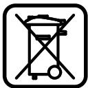
According to the European Directive 2002/96/EC on waste electrical and electronic equipment and its implementation in national law,
power tools that are no longer usable must be collected separately and disposed of in an environmentally correct manner.
MOXANBI 3miHn.
Robert Bosch GmbH, Dept. PT/ESC,
D-70745 Leinfelden-Echterdingen
Dr. Egbert Schneider
Dr. Eckerhard Strötgen
Senior Vice President
Head of Product
Engineering
Certification
ppa. Maee i.v. Nooey
Robert Bosch GmbH, Power Tools Division
D-70745 Leinfelden-Echterdingen
Bosch Service Center
Str. Horia Macelariu Nr. 30-34, 013937 Bucuresti
Tel. Service scule electrice: +40 (021) 4 05 75 40
Fax: +40 (021) 405 7566
E-Mail: infoBSC@ro.bosch.com
Tel. Technical consulting: +40 (021) 4 05 75 39
Fax: +40 (021) 405 7566
E-Mail: infoBSC@ro.bosch.com
www.bosch-romania.ro
Disposal
Power tools, accessories and packaging must be directed to an ecological recycling station.
Dr. Egbert Schneider Senior Vice President Engineering
Dr. Eckerhard Strötgen Head of Product Certification
ppa. Maee i.v. Nooey
Robert Bosch GmbH, Power Tools Division D-70745 Leinfelden-Echterdingen Leinfelden, 22.07.2010
Mounting
Warning: Before mounting and before any work on the power tool, the plug must be pulled out of the socket.
Scope of delivery

NOTE: The image of the contents at the beginning of the manual for operation.
Before using the power tool, check that all parts listed in the contents are present:
Circular saw for pre-cutting, saw blade - protective cover 19, hex key 14 (2x), screw clamp 16, six-sided key 25 - batteries (2x, size LR03, 1.5 V)
Warning: Check the power tool for external damage.
Before continuing to use the power tool, you must carefully check that the parts are not damaged. Damaged parts must function properly and according to their intended purpose. Check that the moving parts function properly and do not jam, and that no parts are damaged. Every part must be mounted correctly and meet all conditions for safe operation.
Damaged parts must be repaired or replaced by an authorized service center for power tools.
Tools needed for assembly:
- Phillips screwdriver
Assembly of parts
- Remove all included parts from the packaging. Remove all packaging material from the power tool and the included parts. To facilitate assembly of the included parts, the power tool should be in the transport position.
Inserting the batteries (see Fig. A)
- Open the cover of the battery compartment 31. Insert the included battery, observing the polarity.
- Close the cover of the battery compartment.
Mounting the work table extensions (see Fig. B)
The work table extensions must be mounted on both sides of the power tool.
The mounting kit allows several mounting options for the work piece (see figure H).
Depending on the need, place the work piece plate 14 in the channel 28 of the power tool or in the channel 32 of the auxiliary work piece plate.
Stationary or mobile mounting
For safe operation with the power tool, before using it, you must mount it on a flat and stable work surface (e.g., a workbench).
Mounting on a work surface (see figure D1)
- Insert the support bracket 10 so that the power tool stands stably on the work surface.
- Fasten the power tool with suitable screws to the work surface. For this, use the holes 7.
Mounting on a work stand (see figure D2)
Work stands (e.g., PTA 2400) allow the power tool to be placed on a raised surface thanks to the adjustable legs. The support surfaces of the work stands serve to support long workpieces.
Note: In such a case of supporting long workpieces, use only the support surfaces of the stand, not the work piece plate 14 of the power tool.
► Read all safety warnings and instructions supplied with the stand. Failure to follow the warnings and instructions may result in electric shock, fire, and/or serious injury. ► When mounting the power tool, carefully and correctly attach it to the stand. Correct attachment of the stand is important to avoid the risk of it suddenly tipping over during operation. Mount the power tool to the stand before transporting it.
Dust extraction system
Dusts from processing materials such as lead-containing paint, some types of wood, minerals, and metals can be harmful to health. Contact with or inhalation of such dusts can cause allergic reactions and/or respiratory diseases in the operator or bystanders.
Certain dusts, e.g., from processing beech or oak, are considered carcinogenic, especially in combination with wood treatment additives (chromate, wood preservatives). Processing of asbestos-containing materials is only allowed by appropriately qualified personnel.
Use a dust extraction system. Ensure good ventilation of the workplace. It is recommended to use a breathing mask with filter class P2.
The tool is intended for processing the relevant materials in accordance with the laws of the country.
The dust extractor can be blocked by the removed parts or details.
Switch off the power tool and unplug it before making contact.
Pull the dust extraction hose off the dust extraction outlet. - Open the dust extraction hose for suction.
Dust extraction system (see Fig. C)
Insert the dust extraction hose into the dust extraction outlet 22 until it engages.
During operation, the dust extraction hose must not come into contact with the moving parts of the power tool.
Empty the dust extraction hose in a timely manner.
Dust extraction system
At the end of the dust extraction outlet 22, you can also connect a vacuum cleaner (0 36 mm).
The vacuum cleaner used must be suitable for working with the processed material.
If during work particularly harmful to health or carcinogenic dust is released, use a specially designed vacuum cleaner.
Changing the tool (see Figures E1-E4)
Before any work on the power tool, pull the mains plug out of the socket. When mounting the circular saw blade, work with protective gloves. There is a risk of injury when mounting the circular saw blade.
Use only sharp saw blades. The maximum permissible speed of rotation is higher than the speed of rotation of the power tool.
The circular saw is designed to comply with the requirements of EN 847-1 and the corresponding marking of conformity.
The circular saw is intended for use with a power tool and is suitable for processing the material you are working with.
Removing the circular saw blade
- Place the power tool in the working position. - Turn the screw with the hex key 25 counterclockwise while simultaneously pressing the spindle lock button 30 until the spindle locks. Hold the spindle lock button 30 and turn the screw 33 counterclockwise (left-hand thread!!). - Remove the flange 34. Press the spindle lock button 30 and turn the clamping nut 5 counterclockwise until it stops. Hold the clamping nut in this position and remove the circular saw blade 36. - Then turn the clamping nut 5 clockwise.
Mounting the circular saw blade
If necessary, clean the parts you are going to mount.
Press the spindle lock button 30, turn the clamping nut 5 counterclockwise until it stops and hold it there. Place the new circular saw blade on the inner flange 35. When mounting, make sure that the direction of rotation of the teeth (marked with an arrow on the circular saw blade) matches the direction of the arrow on the clamping nut! Then turn the clamping nut 5 clockwise. - Place the flange 34 and the screw 33. Press the spindle lock button 30 until the spindle locks, then tighten the screw by turning it counterclockwise.
Working with the power tool
Before starting work with the power tool, always check the safety devices.
Transport lock button (see figure F)
The transport lock button 29 facilitates the transport of the power tool to different work areas.
Releasing the power tool (working position)
Press the frame of the power tool slightly downwards, holding it by the handle 1, to release the transport lock 29. Turn the transport lock button 29 fully. Lift the frame of the power tool upwards.
Locking the power tool (transport position)
- Loosen the locking screw 26, if it is tightened. Pull the frame of the power tool upwards and then tighten the locking screw again. Turn the depth stop 18 until it engages. (See "Setting the depth stop", page 303)
- Press the tool against the wall 8 and then pull the handle 9. Press the switch 3 and simultaneously tilt the tool frame backwards, holding it by the handle 1, until the locking mechanism for transport 29 can be pressed completely.
With this, the power tool is securely locked in the transport position.
Locking the workpiece (see figure G)
To ensure optimal working safety, the workpiece must be locked.
Do not lock workpieces that are too soft to be locked.
- Place the workpiece flat against the support 15. Insert the included screw clamp 16 into the provided holes 23. - Turn the screw with the knurled head 37 and adjust the screw clamp according to the workpiece. Then tighten the knurled head. - Lock the workpiece by turning the screw 38.
Releasing the workpiece
To release the screw clamp, turn the handle 38 counterclockwise.
Adjusting the wall (see figure H)
The workpiece must be placed in its final position.
The mounting system for the workpieces allows a large number of mounting options.
Depending on the requirements, place the workpiece holder 14 either in the channel 28 of the power tool or in the channel 32 of the second workpiece holder.
Adjusting the bevel angle
Before adjusting the bevel angle, never press the start switch 20. If you switch on the power tool unintentionally, there is a risk of injury.
Adjusting the bevel angle in the horizontal plane
The blade tilt in the horizontal plane can be adjusted in the range from -47° (left) to 47° (right).
If the locking lever for the miter angle is tightened, loosen it. Turn the table 8 to the left or right, holding the lever, until the pointer on the scale 12 indicates the desired miter angle in the horizontal plane. Then tighten the locking lever for the miter angle 9.
For quick and precise adjustment of the most commonly used miter angles, the table 8 has fixed stops with the following standard angles:
-45° / -30° / -22.5° / -15° /
0° / 15° / 22.5° / 30° / 45°
Adjusting the blade tilt in the vertical plane (see Fig. 1)
The blade tilt in the vertical plane can be adjusted in the range from 0° to 45°.
- Loosen the lever 17. Tilt the head of the power tool, holding it by the lever 1, until the pointer 39 aligns with the desired angle.
- Hold the head of the power tool in this position and tighten the lever 17 again.
For quick and precise adjustment of the standard tilt angles 0° and 45°, there are preset limit stops in the housing.
- Loosen the lever 17.
- To set the tilt, hold the head of the power tool by the lever 1 and tilt it to the right stop (0°) or to the left stop (45°).
- Tighten the locking lever 17 again.
Permissible workpiece dimensions and maximum dimensions:
| Hak尔OH
хорион-
тално | Вернекалho | Височиах
широчиа |
| 0° | 0° | 40 x 220 mm |
| 45° | 0° | 40 x 150 mm |
| 0° | 45° | 18 x 220 mm |
| 45° | 45° | 18 x 150 mm |
Minimum workpiece dimensions (= the smallest pieces that can be clamped with the included screw clamp 16, both vertically and horizontally on the circular saw blade): 100 x 40 mm (length x width)
Marking at the setting (0° / 0°): 40 mm


Cutting without feeding (cutting to length) (see figure M)
- For cutting without advancing (small parts), if necessary, loosen the locking screw 26. Move the tool carriage to the stop 5 along the guide. Tighten the screw 26.
- Set the stop according to the desired part size. Adjust the cutting depth. Switch on the power tool. Guide the tool carriage slowly and evenly with both hands.
- Cut the part with uniform feed. Switch off the power tool and wait until the circular saw blade has come to a complete stop. Raise the tool carriage carefully.
Cutting with feed
- For cutting with the aid of the feeding device 41 (small parts), if necessary, loosen the locking screw 26. Set the stop according to the desired part size.
- Adjust the cutting depth. Move the tool carriage away from the stop 5 until the circular saw blade is close to the part. Switch on the power tool. Guide the tool carriage slowly and evenly with both hands.
- Then, pressing the carriage against the stop 15, cut the part with uniform feed. Switch off the power tool and wait until the circular saw blade has come to a complete stop. Raise the tool carriage carefully.
Adjusting the depth stop (cutting grooves) (see figure N)
If you want to cut grooves, you must set the depth stop accordingly.
Lower the tool carriage, holding it by the handle 1, until the desired groove depth is reached. Tighten the depth stop 18 against the stop plate, until its tip touches the housing 42. Raise the tool carriage again.
Replacing the saw blade (see figure O)
After prolonged use of the power tool, the red saw blade 11 may become worn.
Replace the worn saw blade.
To replace the tool, position it in the working position. Using a Phillips screwdriver, loosen the screws and remove the old blade. Place the new blade and retighten all screws.
Working on the profile of the blade
You can work on the profile of the blade in two different ways:
Depending on the support
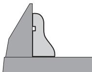
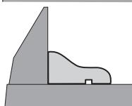
Depending on the width of the profile blade, you can change the blades with or without extraction.
First, try the adjustment of the cut on a piece of scrap pipe.

Transport (see figure P)
Before transporting the power tool, you must remove the following parts:
Place the power tool in the transport position. Insert the locking pin 14 into the front groove 28 of the power tool. Remove all accessories that cannot be mounted safely to the power tool.
Before each work, clean the dust and shavings with a vacuum cleaner or a dry brush.
Clean the tool regularly.
Accessories
Circular saw blades for wood and plastic, aluminum and blades
Circular saw blade 190 x 30 mm, 40 teeth .2609256821
Blade DNCK 190 x 30 mm, 12 teeth. 2 609 256 868
Blade DNCK 190 x 30 mm, 24 teeth. 2 608 640 615
Blade DNCK 190 x 30 mm, 60 teeth. 2 608 641 188
Service and consultation
The service department will answer your questions regarding repair and maintenance of your product, as well as spare parts. Exploded views and information on spare parts can also be found at www.bosch-pt.com
The Bosch consultation team will be happy to help you with any questions regarding the purchase, use, and adjustment of the various products and accessories from the Bosch range.
Robert Bosch EOOD - Sofia
Bosch Service Center
Warranty and repair service
ul. Srebarna No. 3-9
1907 Sofia
Tel.: +359 (02) 9625302
Tel.: +359 (02) 962 5427
Tel.: +359 (02) 962 5295
Fax: +359 (02) 62 46 49
Disposal
Power tools, accessories and packaging should be sorted for environmentally friendly recycling.
Do not dispose of power tools into household waste!
Only for EU countries:
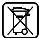
According to the European Directive 2002/96/EC on waste electrical and electronic equipment and its implementation in national law,
power tools that are no longer
usable must be collected separately and disposed of in an environmentally correct manner for recycling.
Subject to change without notice.
Safety Instructions
General Power Tool Safety Warnings

WARNING
When using power tools, basic safety precautions must always be followed
to reduce the risk of electric shock, personal injury, and fire.
Read all these warnings before using this power tool and keep the safety instructions for future reference.
The term "power tool" used in the safety warnings refers to mains-operated power tools (with a mains cable) and battery-operated power tools (without a mains cable).
1) Safety at the workplace
a) Keep your work area clean and well lit. Cluttered or unlit work areas can lead to accidents. b) Do not work with a power tool in an environment at risk of explosion, in which there are flammable liquids, gases or dust. Power tools create sparks that can ignite dust or fumes. c) Keep children and other people away while using the power tool. While working, you can lose control of the device.
2) Electrical safety
a) The plug of the power tool must match the socket. The plug must never be modified. Do not use adapter plugs together with earthed power tools. Unmodified plugs and matching sockets reduce the risk of electric shock. b) Avoid body contact with earthed surfaces such as pipes, heaters, stoves and refrigerators. There is an increased risk of electric shock if your body is earthed. c) Keep the device as far away from rain or moisture as possible. Water entering the power tool increases the risk of electric shock.
d) Do not carry the power tool by the cable, do not hang it, and do not pull it out of the socket. Keep the cable away from heat, oil, sharp edges or moving parts of the device. Damaged or tangled cables increase the risk of electric shock. e) If you work with the power tool outdoors, use only extension cables that are suitable for outdoor use. Using an earthed extension cable suitable for outdoor use reduces the risk of electric shock. f) If work with the power tool cannot be avoided in a damp environment, use a residual current device (RCD) protected supply. The use of an RCD reduces the risk of electric shock.
3) Personal safety
Dr. Egbert Schneider Senior Vice President Engineering
Dr. Eckerhard Strötgen Head of Product Certification
ppa. Maee i.v. Nogcu
Robert Bosch GmbH, Power Tools Division D-70745 Leinfelden-Echterdingen Leinfelden, 22.07.2010
Assembly
Avoid unintentional starting of the power tool. During assembly and for all work on the power tool, the mains plug must not be connected to the power supply.
Scope of delivery

Pay attention to the scope of delivery shown at the beginning of the operating instructions.
Before first use of the power tool, check that all the parts listed below have been supplied.
- Jigsaw with fitted saw blade
- Dust bag 19
- Extension table for sawing 14 (2x) Clamp 16
- Hex key 25 Batteries (2x, size LR03, 1.5 V)
Instructions: Check the power tool for any damage.
Dr. Egbert Schneider Senior Vice President Engineering
Dr. Eckerhard Strötgen Head of Product Certification
ppa. Maee i.v. Nogcu
Robert Bosch GmbH, Power Tools Division D-70745 Leinfelden-Echterdingen Leinfelden, 22.07.2010
Assembly
Avoid unintentional starting. Before assembly and all work on the power tool, pull the mains plug out of the socket.
Scope of delivery

Dr. Egbert Schneider Senior Vice President Engineering
Dr. Eckerhard Strötgen Head of Product Certification
Robert Bosch GmbH, Power Tools Division D-70745 Leinfelden-Echterdingen Leinfelden, 22.07.2010
Assembly
General safety instructions
ATTENTION
Dr. Egbert Schneider Senior Vice President Engineering
Dr. Eckerhard Strötgen Head of Product Certification
Robert Bosch GmbH, Power Tools Division D-70745 Leinfelden-Echterdingen Leinfelden, 22.07.2010
Assembly
General safety instructions
Dr. Egbert Schneider Senior Vice President Engineering
Dr. Eckerhard Strötgen Head of Product Certification
Robert Bosch GmbH, Power Tools Division D-70745 Leinfelden-Echterdingen Leinfelden, 22.07.2010
Assembly
Prevent unintentional starting of the power tool. During assembly and maintenance, the power tool's plug must not be connected to the mains socket.
Delivery scope

Regularly clean the guide roller 6.
Accessories
Saw blade for wood and sheet materials, panels, and strips
Saw blade 190× 30mm 40 teeth .2609256821
Saw blade 190× 30mm 12 teeth . 2609 256 868
Saw blade 190× 30mm 24 teeth .2608640615
Saw blade 190× 30mm 60 teeth .2608641 188
Dr. Egbert Schneider Dr. Eckerhard Strötgen Senior Vice President Head of Product Engineering Certification
ppa. Maee i.v. Nogcu
Robert Bosch GmbH, Power Tools Division D-70745 Leinfelden-Echterdingen Leinfelden, 22.07.2010
Assembly