
GCO 14-24 J Professional - Miter saw BOSCH - Free user manual and instructions
Find the device manual for free GCO 14-24 J Professional BOSCH in PDF.

| Product type | Miter saw (disc cutter) |
| Brand | Bosch |
| Model | GCO 14-24 J Professional |
| Rated power input | 2400 W |
| No-load speed | 3800 min⁻¹ |
| Weight (according to EPTA-Procedure 01:2014) | 18.0 kg |
| Max disc diameter | 355 mm |
| Max disc thickness | 3 mm |
| Disc bore | 25.4 mm |
| Miter angle range | 0° to 45° |
| Power supply | Mains 230 V (220 V compatible) |
| Soft start | Yes |
| Sound pressure level | 101 dB(A) |
| Sound power level | 112 dB(A) |
| Protective guard | Pivoting |
| Spindle lock | Yes |
| Transport handle | Yes |
| Angular stop | Adjustable and movable |
| Clamping system | Locking rod with spindle handle |
| Main use | Cutting metals (not for wood) |
| Mounting | Stationary on workbench recommended |
| Maintenance | Regular cleaning of ventilation slots |
| Spare parts and repairability | Available via Bosch after-sales service |
| Workpiece dimensions (max) | Diameter 129 mm, section 100 x 196 mm (0°) |
Frequently Asked Questions - GCO 14-24 J Professional BOSCH
User questions about GCO 14-24 J Professional BOSCH
0 question about this device. Answer the ones you know or ask your own.
Ask a new question about this device
Download the instructions for your Miter saw in PDF format for free! Find your manual GCO 14-24 J Professional - BOSCH and take your electronic device back in hand. On this page are published all the documents necessary for the use of your device. GCO 14-24 J Professional by BOSCH.
USER MANUAL GCO 14-24 J Professional BOSCH
natural_image
3D rendering of a mechanical cutting tool with a flat blade and base mount (no text or symbols visible)
Robert Bosch Power Tools GmbH
70538 Stuttgart GERMANY
www.bosch-pt.com
1609 92A 531 (2019.04) PS / 259

1 609 92A 531
GCO 14-24 J Professional
HEAVY
DUTY

BOSCH
English ...... Page 14
Français......Page 21
natural_image
Close-up of a mechanical component with a cross symbol on its surface (no text or labels visible)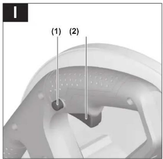
Bosch Power Tools 1 609 92A 531 | (16.04.2019)
Deutsch
Sicherheitshinweise
General Power Tool Safety Warnings
WARNING
Read all safety warnings, instructions, illustrations and specifica-
tions provided with this power tool. Failure to follow all instructions listed below may result in electric shock, fire and/or serious injury.
Save all warnings and instructions for future reference.
The term "power tool" in the warnings refers to your mains-operated (corded) power tool or battery-operated (cordless) power tool.
WARNING! When using electric tools basic safety precautions should always be followed to reduce the risk of fire, electric shock and personal injury including the following. Read all these instructions before attempting to operate this product and save these instructions.
Work area safety
▶ Keep work area clean and well lit. Cluttered or dark areas invite accidents.
▶ Do not operate power tools in explosive atmospheres, such as in the presence of flammable liquids, gases or dust. Power tools create sparks which may ignite the dust or fumes.
▶ Keep children and bystanders away while operating a power tool. Distractions can cause you to lose control.
Electrical safety
▶ Power tool plugs must match the outlet. Never modify the plug in any way. Do not use any adapter plugs with earthed (grounded) power tools. Unmodified plugs and matching outlets will reduce risk of electric shock.
▶ Avoid body contact with earthed or grounded surfaces, such as pipes, radiators, ranges and refrigerators. There is an increased risk of electric shock if your body is earthed or grounded.
▶ Do not expose power tools to rain or wet conditions. Water entering a power tool will increase the risk of electric shock.
▶ Do not abuse the cord. Never use the cord for carrying, pulling or unplugging the power tool. Keep cord away from heat, oil, sharp edges or moving parts.
Damaged or entangled cords increase the risk of electric shock.
When operating a power tool outdoors, use an extension cord suitable for outdoor use. Use of a cord suitable for outdoor use reduces the risk of electric shock.
▶ If operating a power tool in a damp location is unavoidable, use a residual current device (RCD) protected supply. Use of an RCD reduces the risk of electric shock.
Personal safety
▶ Stay alert, watch what you are doing and use common sense when operating a power tool. Do not use a power tool while you are tired or under the influence of drugs, alcohol or medication. A moment of inattention while operating power tools may result in serious personal injury.
▶ Use personal protective equipment. Always wear eye protection. Protective equipment such as a dust mask, non-skid safety shoes, hard hat or hearing protection used for appropriate conditions will reduce personal injuries.
▶ Prevent unintentional starting. Ensure the switch is in the off-position before connecting to power source and/or battery pack, picking up or carrying the tool.
Carrying power tools with your finger on the switch or energising power tools that have the switch on invites accidents.
Remove any adjusting key or wrench before turning the power tool on. A wrench or a key left attached to a rotating part of the power tool may result in personal injury.
▶ Do not overreach. Keep proper footing and balance at all times. This enables better control of the power tool in unexpected situations.
▶ Dress properly. Do not wear loose clothing or jewellery. Keep your hair and clothing away from moving parts. Loose clothes, jewellery or long hair can be caught in moving parts.
If devices are provided for the connection of dust extraction and collection facilities, ensure these are connected and properly used. Use of dust collection can reduce dust-related hazards.
▶ Do not let familiarity gained from frequent use of tools allow you to become complacent and ignore tool safety principles. A careless action can cause severe injury within a fraction of a second.
Power tool use and care
▶ Do not force the power tool. Use the correct power tool for your application. The correct power tool will do the job better and safer at the rate for which it was designed.
▶ Do not use the power tool if the switch does not turn it on and off. Any power tool that cannot be controlled with the switch is dangerous and must be repaired.
▶ Disconnect the plug from the power source and/or remove the battery pack, if detachable, from the power tool before making any adjustments, changing accessories, or storing power tools. Such preventive safety measures reduce the risk of starting the power tool accidentally.
▶ Store idle power tools out of the reach of children and do not allow persons unfamiliar with the power tool or these instructions to operate the power tool. Power tools are dangerous in the hands of untrained users.
- Maintain power tools and accessories. Check for misalignment or binding of moving parts, breakage of parts and any other condition that may affect the power tool's operation. If damaged, have the power tool repaired before use. Many accidents are caused by poorly maintained power tools.
▶ Keep cutting tools sharp and clean. Properly maintained cutting tools with sharp cutting edges are less likely to bind and are easier to control.
▶ Use the power tool, accessories and tool bits etc. in accordance with these instructions, taking into account the working conditions and the work to be performed. Use of the power tool for operations different from those intended could result in a hazardous situation.
▶ Keep handles and grasping surfaces dry, clean and free from oil and grease. Slippery handles and grasping surfaces do not allow for safe handling and control of the tool in unexpected situations.
Service
▶ Have your power tool serviced by a qualified repair person using only identical replacement parts. This will ensure that the safety of the power tool is maintained.
Cut-off machine safety warnings
▶ Position yourself and bystanders away from the plane of the rotating wheel. The guard helps to protect the operator from broken wheel fragments and accidental contact with wheel.
▶ Use only bonded reinforced cut-off wheels for your power tool. Just because an accessory can be attached to your power tool, it does not assure safe operation.
The rated speed of the accessory must be at least equal to the maximum speed marked on the power tool. Accessories running faster than their rated speed can break and fly apart.
▶ Wheels must be used only for recommended applications. For example: do not grind with the side of a cut-off wheel. Abrasive cut-off wheels are intended for peri-
pheral grinding, side forces applied to these wheels may cause them to shatter.
▶ Always use undamaged wheel flanges that are of correct diameter for your selected wheel. Proper wheel flanges support the wheel thus reducing the possibility of wheel breakage.
The outside diameter and the thickness of your accessory must be within the capacity rating of your power tool. Incorrectly sized accessories cannot be adequately guarded or controlled.
The arbour size of wheels and flanges must properly fit the spindle of the power tool. Wheels and flanges with arbour holes that do not match the mounting hardware of the power tool will run out of balance, vibrate excessively and may cause loss of control.
Do not use damaged wheels. Before each use, inspect the wheels for chips and cracks. If the power tool or wheel is dropped, inspect for damage or install an undamaged wheel. After inspecting and installing the wheel, position yourself and bystanders away from the plane of the rotating wheel and run the power tool at maximum no load speed for one minute. Damaged wheels will normally break apart during this test time.
▶ Wear personal protective equipment. Depending on application, use face shield, safety goggles or safety glasses. As appropriate, wear dust mask, hearing protectors, gloves and shop apron capable of stopping small abrasive or workpiece fragments. The eye protection must be capable of stopping flying debris generated by various operations. The dust mask or respirator must be capable of filtrating particles generated by your operation. Prolonged exposure to high intensity noise may cause hearing loss.
▶ Keep bystanders a safe distance away from work area. Anyone entering the work area must wear personal protective equipment. Fragments of workpiece or of a broken wheel may fly away and cause injury beyond immediate area of operation.
▶ Position the cord clear of the spinning accessory. If you lose control, the cord may be cut or snagged and your hand or arm may be pulled into the spinning wheel.
▶ Regularly clean the power tool's air vents. The motor's fan can draw the dust inside the housing and excessive accumulation of powdered metal may cause electrical hazards.
▶ Do not operate the power tool near flammable materials. Do not operate the power tool while placed on a combustible surface such as wood. Sparks could ignite these materials.
▶ Do not use accessories that require liquid coolants. Using water or other liquid coolants may result in electrocution or shock.
Kickback and related warnings
Kickback is a sudden reaction to a pinched or snagged rotating wheel. Pinching or snagging causes rapid stalling of the
16 | English
rotating wheel which in turn causes the uncontrolled cutting unit to be forced upwards toward the operator.
For example, if an abrasive wheel is snagged or pinched by the workpiece, the edge of the wheel that is entering into the pinch point can dig into the surface of the material causing the wheel to climb out or kick out. Abrasive wheels may also break under these conditions.
Kickback is the result of power tool misuse and/or incorrect operating procedures or conditions and can be avoided by taking proper precautions as given below.
Maintain a firm grip on the power tool and position your body and arm to allow you to resist kickback forces. The operator can control upward kickback forces, if proper precautions are taken.
▶ Do not position your body in line with the rotating wheel. If kickback occurs, it will propel the cutting unit upwards toward the operator.
▶ Do not attach a saw chain, woodcarving blade, segmented diamond wheel with a peripheral gap greater than 10 mm or toothed saw blade. Such blades create frequent kickback and loss of control.
Do not "jam" the wheel or apply excessive pressure. Do not attempt to make an excessive depth of cut. Overstressing the wheel increases the loading and susceptibility to twisting or binding of the wheel in the cut and the possibility of kickback or wheel breakage.
When the wheel is binding or when interrupting a cut for any reason, switch off the power tool and hold the cutting unit motionless until the wheel comes to a complete stop. Never attempt to remove the wheel from the cut while the wheel is in motion otherwise kickback may occur. Investigate and take corrective action to eliminate the cause of wheel binding.
▶ Do not restart the cutting operation in the workpiece. Let the wheel reach full speed and carefully re-enter the cut. The wheel may bind, walk up or kickback if the power tool is restarted in the workpiece.
▶ Support any oversized workpiece to minimize the risk of wheel pinching and kickback. Large workpieces tend to sag under their own weight. Supports must be placed under the workpiece near the line of cut and near the edge of the workpiece on both sides of the wheel.
Additional safety information
▶ Store the power tool safely when it is not in use. The storage location must be dry and lockable. This prevents the power tool from storage damage, and from being operated by untrained persons.
▶ Always firmly clamp the workpiece into place. Do not carry out work on workpieces that are too small to be clamped. Otherwise, the distance between your hand and the rotating cutting disc will be too small.
▶ Check the cable regularly and have a damaged cable repaired only by an authorised customer service agent for Bosch power tools. Replace damaged exten-
sion cables. This will ensure that the safety of the power tool is maintained.
▶ Never stand on the power tool. Serious injuries may occur if the power tool tips over or if you inadvertently come into contact with the saw blade.
▶ Always use the protective guard. The protective guard protects users from any parts that break off from the cutting disc and prevents unintentional contact with the cutting disc.
▶ Do not brake the cutting disc to a stop by applying side pressure after switching the power tool off. The cutting disc can be damaged, break or cause kickback.
Products sold in GB only:
Your product is fitted with an BS 1363/A approved electric plug with internal fuse (ASTA approved to BS 1362). If the plug is not suitable for your socket outlets, it should be cut off and an appropriate plug fitted in its place by an authorised customer service agent. The replacement plug should have the same fuse rating as the original plug.
The severed plug must be disposed of to avoid a possible shock hazard and should never be inserted into a mains socket elsewhere.
▶ Never leave the tool unattended before it has come to a complete stop. Cutting tools that are still running can cause injuries.
Symbols
The following symbols may be important for the operation of your power tool. Please take note of these symbols and their meaning. Correctly interpreting the symbols will help you to operate the power tool more effectively and safely.
Symbols and their meanings

Keep hands away from the cutting area while the power tool is running. Contact with the cutting blade can lead to injuries.

Wear hearing protection. Exposure to noise can cause hearing loss.

Wear safety goggles.

Wear a dust mask.
Symbols and their meanings

Wear protective gloves. Cutting discs have sharp edges and become very hot during operation.
Product Description and Specifications

Read all the safety and general instructions.
Failure to observe the safety and general instructions may result in electric shock, fire and/or serious injury.
Please observe the illustrations at the beginning of this operating manual.
Intended use
The power tool is a stationary machine that uses cutting discs to cut metal materials with and against the grain, in straight lines and at mitre angles up to 45°, without the use of water.
Using diamond-tipped cutting discs is not permitted.
Product Features
The numbering of the product features refers to the diagram of the power tool on the graphics page.
(1) Lock-off button for on/off switch
(2) On/off switch
(3) Handle
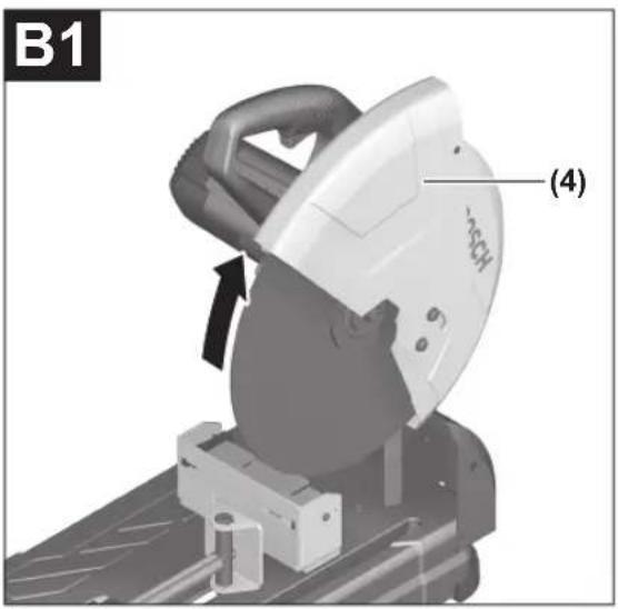
(4) Retracting blade guard
(5) Spindle lock
(6) Cutting disc
(7) Angle guide
(8) Locking spindle
(9) Quick release
(10) Spindle handle
(11) Mounting holes
(12) Hex key (8 mm)
(13) Base plate
(14) Clamping jaw
(15) Workpiece support for workpieces with cross section of max. 40 x 40 mm
(16) Locking screw for angle guide
(17) Transport safety lock
(18) Tool arm
(19) Transport handle
(20) Protective guard
(21) Spark guard plate
(22) Tool spindle
(23) Clamping flange
(24) Washer
(25) Hexagon screw
Technical Data
| Cut-off grinder GCO 14-24 J | ||
| Article number | 3 601 M37 2.. | |
| Rated power input W 2400 | ||
| No-load speed min | -1 | 3800 |
| Soft start ● | ||
| Weight according to EPTA-Procedure 01:2014 | kg 18.0 | |
| Protection class | / II | |
Permitted workpiece dimensions (maximum/minimum): (see "Permissible workpiece dimensions", page 20)
The specifications apply to a rated voltage [U] of 230 V. These specifications may vary at different voltages and in country-specific models.
Dimensions of suitable cutting discs
| Max. cutting disc diameter mm 355 | |
| Max. cutting disc thickness mm 3 | |
| Hole diameter mm 25.4 |
Noise Information
Noise emission values determined according to EN 62841-3-10.
Typically, the A-weighted noise level of the power tool is: Sound pressure level 101 dB(A); sound power level 112 dB(A). Uncertainty K=3 dB.
Wear hearing protection!
The noise emission value given in these instructions has been measured in accordance with a standardised measuring procedure and may be used to compare power tools. It may also be used for a preliminary estimation of noise emissions.
The noise emission value given represents the main applications of the power tool. However, if the power tool is used for other applications, with different application tools or is poorly maintained, the noise emission value may differ. This may significantly increase noise emissions over the total working period.
To estimate noise emissions accurately, the times when the tool is switched off, or when it is running but not actually being used, should also be taken into account. This may significantly reduce noise emissions over the total working period.
Assembly
▶ Avoid starting the power tool unintentionally. The mains plug must not be connected to the power supply during assembly or when carrying out any kind of work on the power tool.
18 | English
Items included
Carefully remove all parts included in the delivery from their packaging.
Remove all packing material from the power tool and the accessories provided.
Check to ensure that all the parts listed below have been supplied before using the power tool for the first time:
- Cut-off grinder with cutting disc fitted
- Hex key (12)
Note: Check the power tool for possible damage.
Before continuing to use the power tool, carefully check that all protective devices or slightly damaged parts are working perfectly and according to specifications. Check that the moving parts are working perfectly and without jamming; check whether any parts are damaged. All parts must be fitted correctly and all the conditions necessary to ensure smooth operation must be met.
If the protective devices or any parts become damaged, you must have them properly repaired or replaced by an authorised service centre.
Stationary or flexible mounting
To ensure safe handling, the power tool must be mounted on a flat, stable work surface (e.g. work bench) before use.
Mounting on a work surface (see figure A)
- Use suitable screw fasteners to secure the power tool to the work surface. Use the holes (11) to do this.
Flexible installation (not recommended)
In exceptional circumstances, if it is not possible to securely mount the power tool on a work surface, you can improvise by placing the feet of the base plate (13) on an appropriate base (e.g. workbench, flat ground, etc.), without screwing down the power tool.
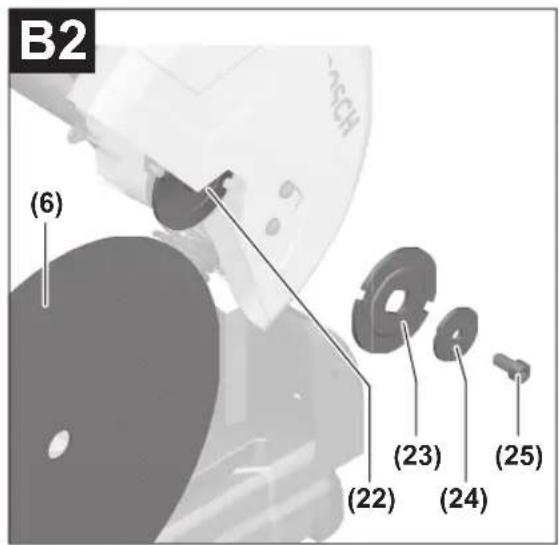
Changing the Tool (see figures B1-B2)
▶ Pull the plug out of the socket before carrying out any work on the power tool.
▶ Do not activate the spindle lock (5) while the tool spindle (22) is moving. The power tool may become damaged if you do this.
▶ Do not touch the cutting disc after use until it has cooled. The cutting disc becomes very hot during use.
Only use cutting discs that match the specifications given in this operating manual and that have been tested and marked in accordance with EN 12413.
Use any intermediate layers provided with the cutting disc.
Place unused cutting discs in an enclosed container or their original packaging. Store the cutting discs lying flat.
Removing the cutting disc
- Bring the power tool into the work position.
-
Swivel the retracting blade guard (4) backwards as far as possible.
-
Turn the hexagon screw (25) using the hex key (12) provided while pressing the spindle lock (5) until it engages.
- Hold the spindle lock down and unscrew the hexagon screw (25).
- Remove the washer (24) and the clamping flange (23).
- Remove the cutting disc (6).
Fitting the cutting disc
If required, clean all the parts you want to fit before installing them.
- Place the new cutting disc on the tool spindle (22) such that the sticker points away from the tool arm.
- Fit the clamping flange (23), the washer (24) and the hexagon screw (25). Press the spindle lock (5) until it engages and retighten the hexagon screw (25) by turning it clockwise. (Tightening torque approx. 18–20 Nm)
- Slowly guide the retracting blade guard (4) all the way down until the cutting disc is completely covered.
- Make sure that the retracting blade guard (4) is working properly.
After fitting the cutting disc, check that the cutting disc is fitted correctly and can turn freely before switching on the power tool.
- Make sure that the cutting disc does not brush against the retracting blade guard (4), the fixed protective guard (20) or any other parts.
- Put the power tool into operation for approx. 30 seconds. If there is substantial vibration, switch the power tool off immediately, remove the cutting disc and then refit it.
Operation
▶ Pull the plug out of the socket before carrying out any work on the power tool.
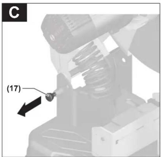
Transport Safety Lock (see figure C)
The transport safety lock (17) makes it easier to handle the power tool when transporting it to various working locations.
Unlocking the power tool (work position)
- Press the tool arm down slightly by the handle (3) to release the transport safety lock (17).
- Pull the transport safety lock (17) all the way out.
- Slowly guide the tool arm upwards.
Note: Make sure that the transport safety lock is not pushed in when working, otherwise the tool arm will not be able to be swivelled to the required depth.
Locking the power tool (transport position)
- Guide the tool arm downwards until you can press the transport safety lock (17) all the way in.
Further information about transporting (see "Transport", page 20).
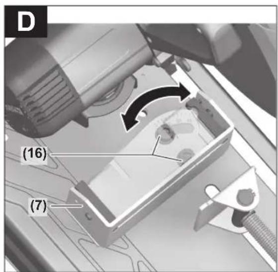
Setting the Mitre Angle (see figure D)
The mitre angle can be set between 0^ and 45^ . Important settings are marked with corresponding markings on the angle guide (7). The 0^ and 45^ positions are secured by the respective end stop.
- Loosen the locking screws (16) on the angle guide using the hex key (12) (8 mm) provided.
- Set the required angle and retighten both locking screws (16).
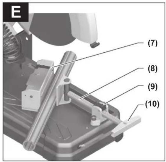
Moving the Angle Guide (see figures D–E)
If you want to cut workpieces more than 140 mm wide, you can move the angle guide (7) backwards.
- Completely unscrew the locking screws (16) using the hex key provided (12) (8 mm).
- Move the angle guide (7) backwards by one or two holes to the required distance.
- Set the required angle and retighten both locking screws (16).
Clamping the workpiece
To ensure maximum safety while working, the workpiece must always be firmly clamped.
Do not saw workpieces that are too small to clamp firmly.
Clamping the Workpiece (see figure E)
- Place the workpiece against the angle guide (7).
- Slide the locking spindle (8) against the workpiece and clamp the workpiece in place using the spindle handle (10).
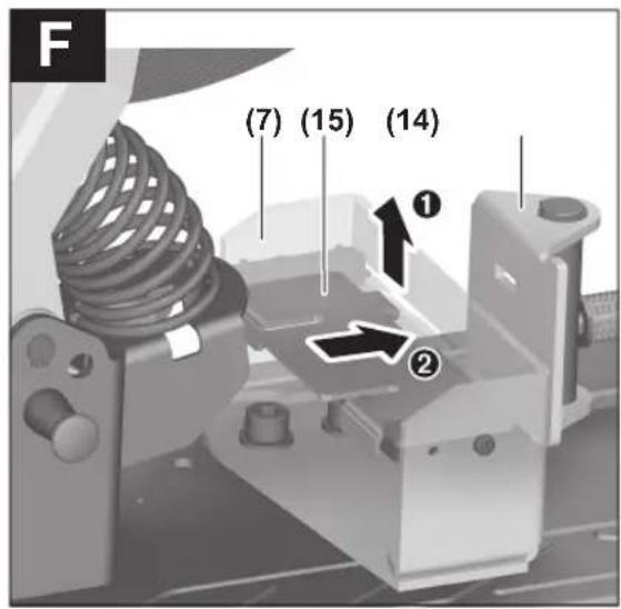
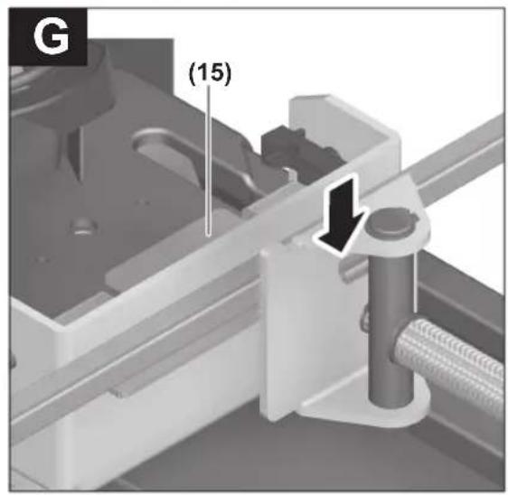
Securing the Workpiece (cross section of max. 40 x 40 mm) (see figures F-H)
- Set the angle guide (7) to the standard 0^ mitre/bevel angle.
- Lift the workpiece support (15) slightly and slide it through the slot in the angle guide.
- Hang the hook of the workpiece support in the opening of the clamping jaw (14).
- Place the workpiece on the workpiece support (15).
- Slide the locking spindle (8) against the workpiece and clamp the workpiece in place using the spindle handle (10).
▶ Ensure that the workpiece support is securely connected to the clamping jaw and does not tip when you place the workpiece on it.
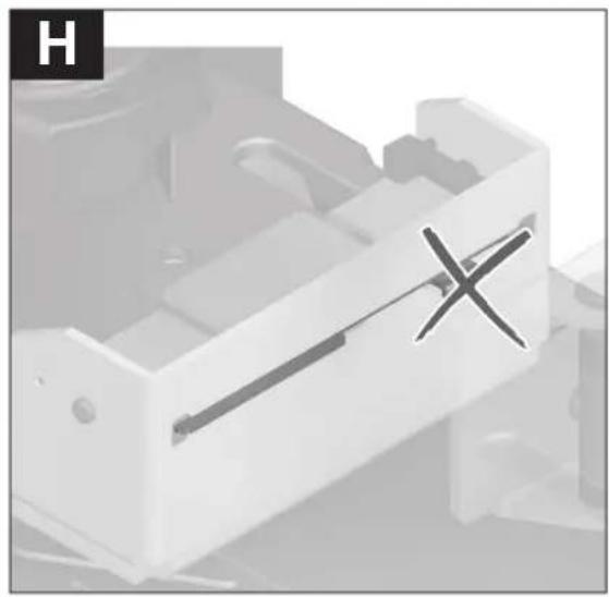
▶ Ensure that the height of the workpiece on the workpiece support is max. 40 mm. Taller workpieces cannot be clamped securely in place.
▶ Ensure that the workpiece support is slid back completely into the angle guide after use. A protruding hook prevents a workpiece from being securely clamped.
Releasing the workpiece
- Release the spindle handle (10).
- Open the quick release (9) and pull the locking spindle (8) away from the workpiece.
Start-up
▶ Pay attention to the mains voltage. The voltage of the power source must match the voltage specified on the rating plate of the charger. Chargers marked 230 V can also be operated at 220 V.
▶ Products that are only sold in AUS and NZ: Use a residual current device (RCD) with a nominal residual current of 30 mA or less.
▶ Check the cutting disc before using it. The cutting disc must be fitted properly and be able to rotate freely. Carry out a test run for at least 30 seconds with no load. Do not use cutting discs that are damaged, run untrue or vibrate during use. Damaged cutting discs can shatter and cause injuries.
The dust from materials such as lead paint, minerals and metal can be harmful to human health. Touching or breathing in this dust can trigger allergic reactions and/or cause respiratory illnesses in the user or in people in the near vicinity.
Certain kinds of metal dust are hazardous, especially in combination with alloys such as zinc, aluminium or chrome. Materials containing asbestos may only be machined by specialists.
- Provide good ventilation at the workplace.
- It is advisable to wear a P2 filter class breathing mask.
The regulations on the materials being machined that apply in the country of use must be observed.
The cutting disc can become blocked by dust, chips or fragments of the workpiece in the recess of the base plate (13).
- Switch the power tool off and pull the mains plug out of the socket.
- Wait until the cutting disc has come to a complete stop.
- Tilt the power tool backwards so that small pieces of the workpiece can fall out of the opening designed for this purpose. If necessary, use a suitable tool to remove all the pieces of workpiece.
- Avoid dust accumulation at the workplace. Dust can easily ignite.
Position of the operator
▶ Do not stand in front of the power tool in line with the cutting disc. Always stand to the side of the cutting disc. If the cutting disc breaks, your body is more protected from possible splinters in this position.
Switching On/Off (see figure I)
- To start, first press the lock-off button (1). Then press the on/off switch (2) and keep it pressed.
Note: For safety reasons, the on/off switch (2) cannot be locked; it must remain pressed throughout operation.
- To switch off, release the on/off switch (2).
20 | English
Soft start
The electronic soft start limits the torque when the power tool is switched on and increases the service life of the motor.
Practical advice
General advice on using cutting discs
▶ Do not touch the cutting disc after use until it has cooled. The cutting disc becomes very hot during use.
▶ Make sure that the spark guard plate (21) is fitted properly. Flying sparks are created when sanding metals.
▶ Protect the cutting disc against impact, shock and grease. Do not subject the cutting disc to lateral pressure.
▶ Do not load the power tool so heavily that it comes to a stop.
Excessive feed significantly reduces the performance of the power tool and the service life of the cutting disc.
▶ Only use cutting discs that are suitable for the material being machined.
Permissible workpiece dimensions
Maximum workpiece dimensions:
| Workpiece shape Mitre angle | |
| 0° 45° | |
| Dia. 129 Dia. 128 | |
| 119 x 119 110 x 110 | |
| 100 x 196 107 x 115 | |
| 130 x 130 115 x 115 | |
Minimum workpiece dimensions
(= all workpieces which can still be clamped in place with the locking spindle (8)): Length 80 mm
Maximum cutting depth (0°/0°): 129 mm
Cutting metal
- Set the required mitre angle as necessary.
- Firmly clamp the workpiece as appropriate for its dimensions.
- Switch on the power tool.
- Slowly guide the tool arm downwards using the handle (3).
- Cut the workpiece, applying uniform feed.
- Switch off the power tool and wait until the cutting disc has come to a complete stop.
- Slowly guide the tool arm upwards.
Transport
- Always carry the power tool by the transport handle (19).
▶ Only use the transport devices to transport the power tool and never the protective devices.
Maintenance and Service
Maintenance and Cleaning
▶ Pull the plug out of the socket before carrying out any work on the power tool.
Clean the air vents on your power tool regularly. The motor's fan will draw the dust inside the housing and excessive accumulation of powdered metal may cause electrical hazards.
In extreme conditions, always use a dust extractor if possible. Blow out ventilation slots frequently and install a residual current device (RCD) upstream. When machining metals, conductive dust can settle inside the power tool, which can affect its protective insulation.
▶ Have maintenance and repair work performed exclusively by a qualified specialist. This will ensure that the safety of the power tool is maintained.
The retracting blade guard must always be able to move freely and retract automatically. It is therefore important to keep the area around the retracting blade guard clean at all times.
In order to avoid safety hazards, if the power supply cord needs to be replaced, this must be done by Bosch or by an after-sales service centre that is authorised to repair Bosch power tools.
Accessories
| Article number |
| Cutting discs for all metal materials |
| Cutting disc 355 x 25.4 mm 2 608 600 208 |
| Cutting disc 355 x 25.4 mm 2 608 600 223 |
After-Sales Service and Application Service
Our after-sales service responds to your questions concerning maintenance and repair of your product as well as spare parts. You can find explosion drawings and information on spare parts at: www.bosch-pt.com
The Bosch product use advice team will be happy to help you with any questions about our products and their accessories.
In all correspondence and spare parts orders, please always include the 10-digit article number given on the nameplate of the product.
Great Britain
Robert Bosch Ltd. (B.S.C.)
P.O. Box 98
Broadwater Park
North Orbital Road
Denham Uxbridge
UB 9 5HJ
At www.bosch-pt.co.uk you can order spare parts or arrange the collection of a product in need of servicing or repair.
Tel. Service: (0344) 7360109
E-Mail: boschservicecentre@bosch.com
Ireland
Origo Ltd.
Unit 23 Magna Drive
Magna Business Park
City West
Dublin 24
Tel. Service: (01) 4666700
Fax: (01) 4666888
Australia, New Zealand and Pacific Islands
Robert Bosch Australia Pty. Ltd.
Power Tools
Locked Bag 66
Clayton South VIC 3169
Customer Contact Center
Inside Australia:
Phone: (01300) 307044
Fax: (01300) 307045
Inside New Zealand:
Phone: (0800) 543353
Fax: (0800) 428570
Outside AU and NZ:
Phone: +61 3 95415555
www.bosch-pt.com.au
www.bosch-pt.co.nz
Republic of South Africa
Customer service
Hotline: (011) 6519600
Gauteng - BSC Service Centre
35 Roper Street, New Centre
Johannesburg
Tel.: (011) 4939375
Fax: (011) 4930126
E-mail: bsctools@icon.co.za
KZN - BSC Service Centre
Unit E, Almar Centre
143 Crompton Street
Pinetown
Tel.: (031) 7012120
Fax: (031) 7012446
E-mail: bsc.dur@za.bosch.com
Western Cape - BSC Service Centre
Democracy Way, Prosperity Park
Milnerton
Tel.: (021) 5512577
Fax: (021) 5513223
E-mail: bsc@zsd.co.za
Bosch Headquarters
Midrand, Gauteng
Tel.: (011) 6519600
Fax: (011) 6519880
E-mail: rbsa-hq.pts@za.bosch.com
Disposal
The power tool, accessories and packaging should be recycled in an environmentally friendly manner.

Do not dispose of power tools along with household waste.
Only for EU countries:
According to the European Directive 2012/19/EU on Waste Electrical and Electronic Equipment and its implementation into national law, power tools that are no longer usable must be collected separately and disposed of in an environmentally friendly manner.
Français
Robert Bosch (France) S.A.S.
Calle Robert Bosch No. 405
Stationaire of flexibele montage
Bosch Service Center
Telegrafvej 3
2750 Ballerup
På www.bosch-pt.dk kan der online bestilles reservedele eller oprettes en reparations ordre.
Tlf. Service Center: 44898855
Fax: 44898755
E-Mail: vaerktoej@dk.bosch.com
Bortskaffelse
Bosch Service Center
Telegrafvej 3
2750 Ballerup
Danmark
Tel.: (08) 7501820 (inom Sverige)
Fax:(011)187691
Avfallshantering
Robert Bosch Sp. z o.o.
Bosch Service Center PT
K Vápence 1621/16
692 01 Mikulov
Service scule electrice
Strada Horia Măcelariu Nr. 30-34, sector 1
013937 Bucureşti
Service scule electrice
Strada Horia Măcelariu Nr. 30-34, sector 1
013937 Bucureşti, România
www.bosch-pt.com/bg/bg/
Бракуване
Robert Bosch Morocco SARL