TL 4000 18.0/230 - Lamp Flex - Free user manual and instructions
Find the device manual for free TL 4000 18.0/230 Flex in PDF.

| Product type | Cordless tripod spotlight |
| Brand | Flex |
| Model | TL 4000 18.0/230 |
| Rated voltage (DC) | 18 V |
| Rated voltage (AC) | 220–240 V, 50 Hz |
| Rated current | 1.8 A (without USB) / 2.5 A (with USB) |
| USB port | 5 V, 2.1 A (for charging devices) |
| Weight (without battery) | 8.1 kg |
| Compatible battery | AP 18.0/2.5, AP 18.0/5.0, AP 18.0/8.0 |
| Operating temperature | -10 °C to 40 °C |
| Storage temperature | < 50 °C |
| Charging temperature | 4 °C to 40 °C |
| Recommended charger | 10.8/18.0, CA 18.0-LD |
| Estimated luminous flux | 4000 lumens |
| Brightness levels | 3 (max, medium, min) |
| Auxiliary light rotation | 0–210° |
| Spotlight support rotation | 0–270° |
| Adjustable height | Yes (extension tubes) |
| Suspension bracket (max load) | 6.8 kg |
| Integrated hooks | Yes, for suspension |
| Switches | On module and on tripod |
| Light source | Non-replaceable LED |
| Battery and charger | Not included (sold separately) |
| Cleaning | Clean the ventilation grilles regularly |
Frequently Asked Questions - TL 4000 18.0/230 Flex
User questions about TL 4000 18.0/230 Flex
0 question about this device. Answer the ones you know or ask your own.
Ask a new question about this device
Download the instructions for your Lamp in PDF format for free! Find your manual TL 4000 18.0/230 - Flex and take your electronic device back in hand. On this page are published all the documents necessary for the use of your device. TL 4000 18.0/230 by Flex.
USER MANUAL TL 4000 18.0/230 Flex
natural_image
Technical line drawing of a mechanical device labeled 'FLEX' (no additional text or symbols)en Original operating instructions....14
natural_image
Technical line drawing of a mechanical component with arrows indicating direction (no text or symbols)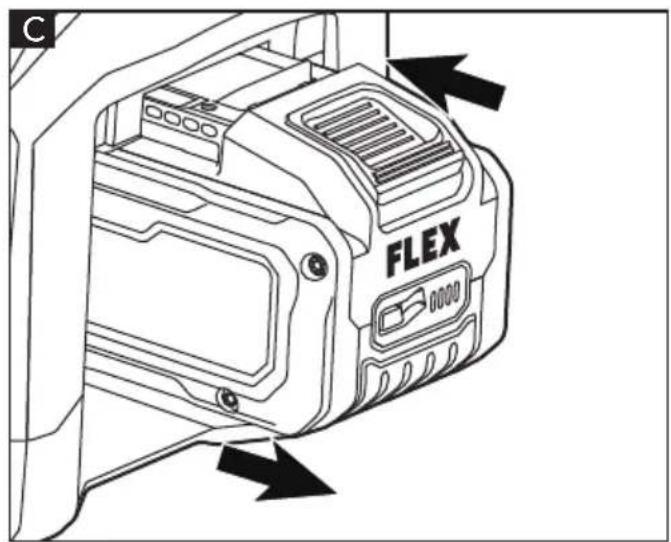

natural_image
Technical diagram of a mechanical assembly with no visible text or symbols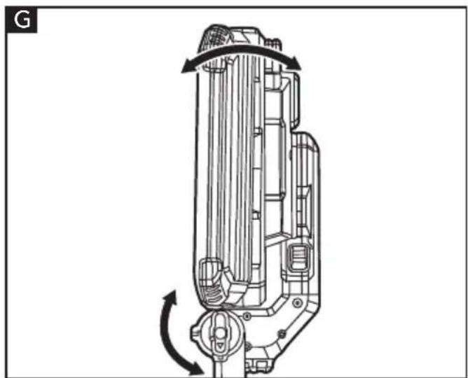
natural_image
Technical line drawing of a mechanical device with rotational arrows indicating motion (no text or symbols)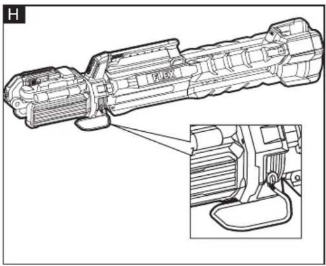
natural_image
Technical line drawing of a mechanical device with an inset close-up showing internal components (no text or symbols)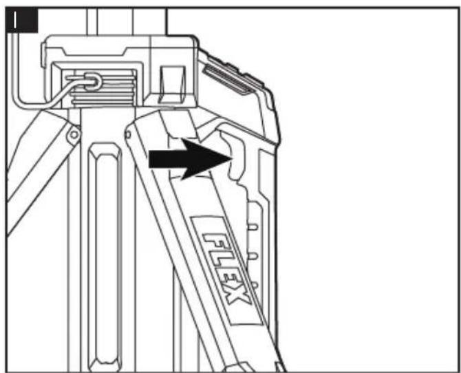
natural_image
Technical line drawing of a mechanical component with two side panels and an FLEX label, showing directional arrows (no text or symbols beyond label)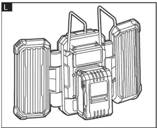
natural_image
Technical line drawing of a multi-stage battery pack assembly (no text or symbols)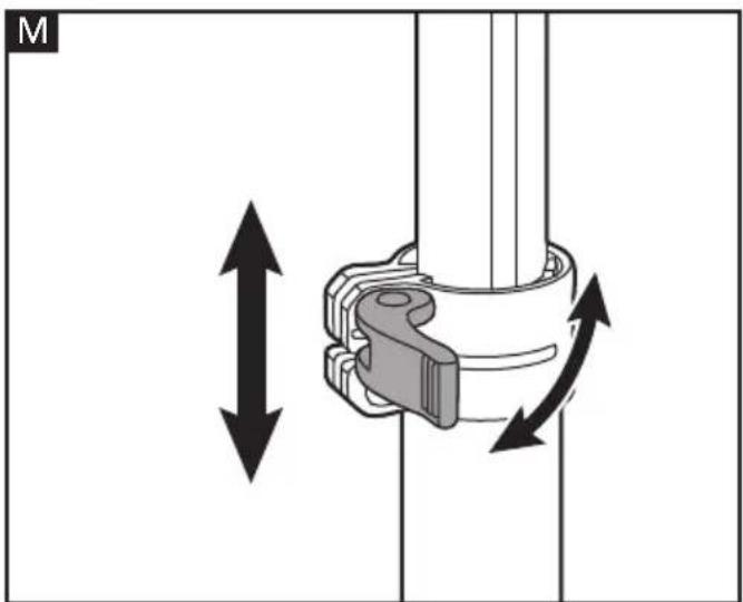
natural_image
Mechanical assembly diagram showing a clamping mechanism with bidirectional arrows indicating motion (no text or symbols)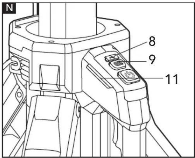
natural_image
Technical line drawing of a mechanical component with no visible text or symbols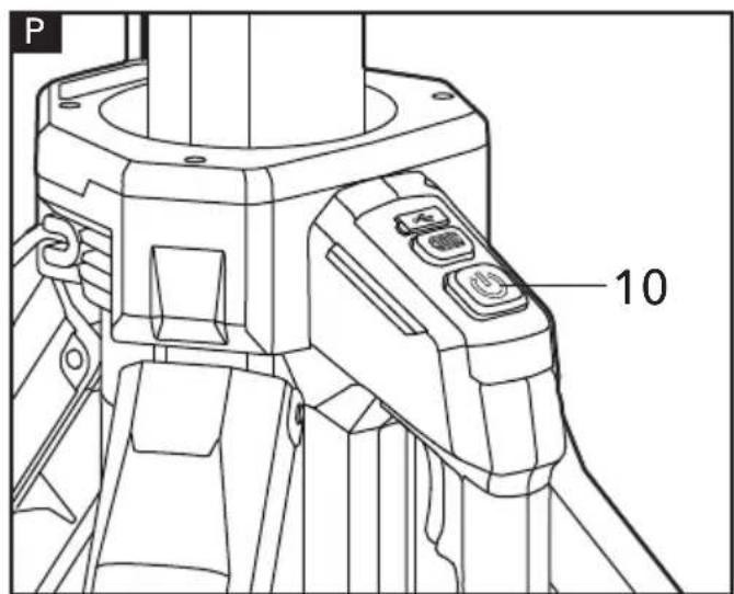
This power tool is state of the art and has been constructed in accordance with the acknowledged safety regulations.
Symbols used in this manual

WARNING!
Denotes impending danger. Non-observance of this warning may result in death or extremely severe injuries.

CAUTION!
Denotes a possibly dangerous situation. Non-observance of this warning may result in slight injury or damage to property.

NOTE
Denotes application tips and important information.
Symbols on the power tool

Do not stare at operating lamp

Class III

To reduce the risk of injury, read the operating instructions!

Disposal information for the old machine (see page 19)!
For your safety

WARNING!
Before using the power tool, please read the follow:
– these operating instructions,
- the "General safety instructions" on the handling of power tools in the enclosed booklet (leaflet-no.: 315.915),
– the currently valid site rules and the regulations for the prevention of accidents.
This power tool is state of the art and has been constructed in accordance with the acknowledged safety regulations.
Nevertheless, when in use, the power tool may be a danger to life and limb of the user or a third party, or the power tool or other property may be damaged.
The cordless tripod light may be used only
-asintended,
– in perfect working order.
Faults which impair safety must be repaired immediately.
Intended use
The tripod light is intended
- for commercial use in industry and trade,
- for workspace lighting.
Safety instructions for tripod light

WARNING!
Read all safety warnings, instructions, illustrations and specifications provided with this power tool. Failure to follow all instructions listed below may result in electric shock, fire and/or serious injury. Save all warnings and instructions for future reference.
■ The light source of this luminaire is not replaceable; when the light source reaches its end of life the whole luminaire shall be replaced.
■ Prevent unintentional starting. Ensure the switch is in the off-position before connecting to battery pack, picking up or carrying the appliance. Carrying the appliance with your finger on the switch or energizing appliance that have the switch on invites accidents.
■ Disconnect the appliance from power source before making any adjustments, changing accessories, or storing appliance. Such preventive safety measures reduce the risk of starting the appliance accidentally.
■ Do not direct the light beam at persons or pets and avoid staring into the light even from a distance.
■ To reduce the risk of injury, do not stare at operating lamp. Serious eye injury could occur.
■ To reduce the risk of burns, do not touch hot lens.
■ Do not operate this light in explosive atmospheres, such as in the presence of flammable liquids, gases or dust. Light create heat which may ignite the dust or fumes.
■ Have servicing performed by a qualified
repairperson using only identical replacement parts. This will ensure that the safety of the product is maintained.
■ Do not modify or attempt to repair the appliance or the battery pack except as indicated in the instructions for use and care.
■ To reduce the risk of injury, close supervision is necessary when a product is used near children.
■ Only use attachments recommended or sold by the manufacturer.
■ Do not use in the rain.
■ To reduce the risk of electrical shock, do not put the appliance in water or other liquid. Do not place or store appliance where it can fall or be pulled into a tub or sink.
■ When using AC power supply, do not unplug by pulling on the cord. To unplug, grasp the plug, not the cord.
■ Recharge battery packs only with the charger specified by the manufacturer. A charger that is suitable for one type of battery pack may create a risk of fire when used with another battery pack.
■ Use appliances only with specifically designated battery packs. Use of any other battery packs may create a risk of injury and fire.
■ When battery pack is not in use, keep it away from other metal objects, like paper clips, coins, keys, nails, screws or other small metal objects, that can make a connection from one terminal to another. Shorting the battery terminals together may cause burns or a fire.
■ Under abusive conditions, liquid may be ejected from the battery; avoid contact. If contact accidentally occurs, flush with water. If liquid contacts eyes, additionally seek medical help. Liquid ejected from the battery may cause irritation or burns.
■ Do not use a battery pack or appliance that is damaged or modified. Damaged or modified batteries may exhibit unpredictable behavior resulting in fire, explosion or risk of injury.
- Do not expose a battery pack or appliance to fire or excessive temperature. Exposure to fire or temperature above 265°F (130°C) may cause explosion.
■ Follow all charging instructions and do
not charge the battery pack or appliance outside of the temperature range specified in the instructions. Charging improperly or at temperatures outside of the specified range may damage the battery and increase the risk of fire.
Technical data
| Tool TL 4000 18.0/23 | 0 | ||
| Type tripod light | |||
| Rated voltage | Vdc | 18 | |
| VAC | 220-240 | ||
| Hz | 50 | ||
| Rated current | A | 1.8 (without USB output) 18V | |
| 2.5(with USB output) 18V | |||
| USB output voltage | V | 5 | |
| USB Output current | A 2.1 | ||
| Auxiliary lights pivot range | °0-210 | ||
| Light holder pivot range | °0-270 | ||
| Weight according to"EPTA Procedure 01/2003" (without battery) | kg 8.1 | ||
| Battery | 18V | AP 18.0/2.5 | |
| AP 18.0/5.0 | |||
| AP 18.0/8.0 | |||
| Weight of battery | Kg | AP 18.0/2.5 | 0.4 |
| AP 18.0/5.0 | 0.7 | ||
| AP 18.0/8.0 | 1.1 | ||
| Working Temperature | -10-40°C | ||
| Storage Temperature | <50°C | ||
| Charging Temperature | 4~40°C | ||
| Charger CA 1 | 0.8/18.0, CA 18.0-LD | ||
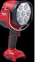
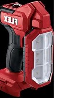
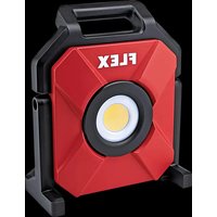
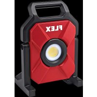
Overview (see figure A)
The numbering of the product features refers to the illustration of the machine on the graphics page.
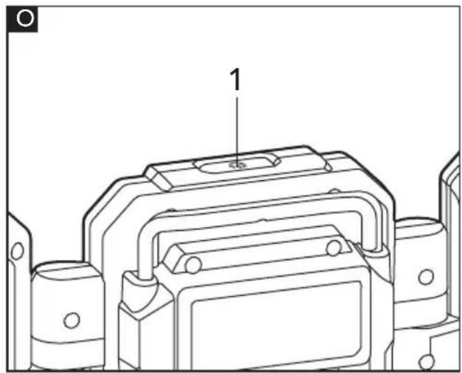
1 On/off switch
2 Hooks
3 Hinges
4 Battery-pack/light-holder interface
5 Light-holder
6 Light release button
7 Light holder angle adjustment knob
8 USB port
9 Power-indicator button
10 On/off switch
11 Power indicator
12 Carrying handle
13 Power bay
14 Legs
15 Main light
16 Auxiliary lights
17 Lens transparent cover
18 Upper extension tube
19 Upper clamp
20 Lower extension tube
21 Lower clamp
22 Center pole
23 Bracket
24 Base
25 Light module
26 Tripod
27 Tripod release switch
Operating instructions
WARNING!
Remove the battery before carrying out any work on the power tool.
Before switching on the power tool
Unpack the cordless tripod light and check that here are no missing or damaged parts.
NOTE
The batteries are not fully charged on delivery. Prior to initial operation, charge the batteries fully. Refer to the charger operating manual.
Inserting/replacing the battery
The battery can be attached directly to the light module 25 or to the power bay 13 on the tripod.
■ Press the charged battery into the power tool until it clicks into place (see figure B &C).
■ To remove, press the release button and pull out the battery (see figure D).
CAUTION!
When the device is not in use, protect the battery contacts. Loose metal parts may short circuit the contacts, explosion and fire hazard!
Using extension cord
CAUTION!
The extension cord and a battery cannot be used at the same time.
Remove the battery from the power bay. Connect a suitable power cord (sold separately) to the AC power inlet located in the power bay 13.
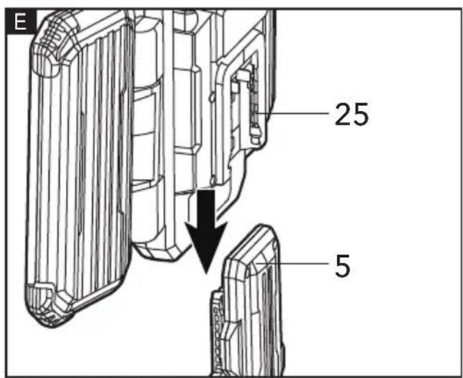
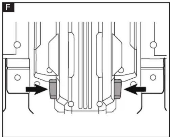
To attach/detach the light module to the tripod
WARNING!
Before attaching the light module 25 to the tripod, please make sure the tripod legs 14 are fully expanded and secured firmly in the locked position.
■ To attach: slide the light module 25 onto the holder 5 (see figure E).
■ To detach: Press the light release buttons 6 inward to release the light module. Pull the light module out and remove it from the holder (see figure F).
To pivot the light holder
The light holder 5 can be pivoted 0-270° to direct the light at a desired spot.
■ Rotate the angle adjustment knob 7 counterclockwise to the position marked with ⚠.
■ Adjust the holder to a desired angle.
■ Rotate the knob clockwise to the position marked with 🔒 to lock the holder (see figure G).
To attach/detach the bracket
When laying the tripod light flat on the ground, the base 24 and the bracket 23 will form a support to protect the light from being damaged.
■ To attach: Spread the ends of the bracket 23 apart and then insert each end into the holes on the tripod (see figure H).
■ To detach: Spread the ends of the bracket 23 apart and then remove the bracket from the tripod.
The bracket can also be used to hang objects on. Maximum weight of the object(s) hung on the bracket cannot exceed 6.8 kg.
To expand/collapse the tripod legs

WARNING!
To reduce the risk of injury from unexpected movement, check to make sure that the tripod does not rock, slide, or move prior to use.

WARNING!
To reduce the risk of injury and damage, do not use the tripod on uneven or inclined surfaces. If you must use the tripod on an inclined surface, secure it with nails or screws.

WARNING!
To reduce the risk of injury, when folding the tripod, keep the other hand away from the tripod legs and be careful not to pinch your fingers.

WARNING!
Do not attempt to modify this product or create accessories or attachments not recommended for use with this product.
Any such alteration or modification is misuse and could result in a hazardous condition leading to possible serious personal injury. The tripod is shipped with the extension tubes retracted and the legs collapsed.
■ Stand the tripod upright on its base.
■ Press the tripod release switch 27 and slide the carrying handle 12 to expand the legs 14 (see figure I).
■ As soon as the legs touch the ground, grab the center pole 22 and lift it up until the legs audibly lock in place.
NOTE: The tripod has two locking positions: the upper locking position, when the tripod is collapsed and the lower locking position, when the tripod is fully expanded.
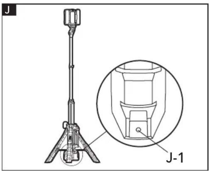
■ There is a 6 mm hole J-1 in the foot of each leg. When using the tripod on an uneven surface, nails or screws can be driven into the hole to secure the tripod (see figure J).
■ To collapse the legs, press the tripod release switch 27 and slide the carrying handle 12 up until the legs audibly lock in place in the upper locking position.

WARNING!
Always ensure the tripod is stable before and after attaching the light module, hanging anything on the bracket, or leaving the tripod unattended. Do not use the tripod light if tripod is unstable.
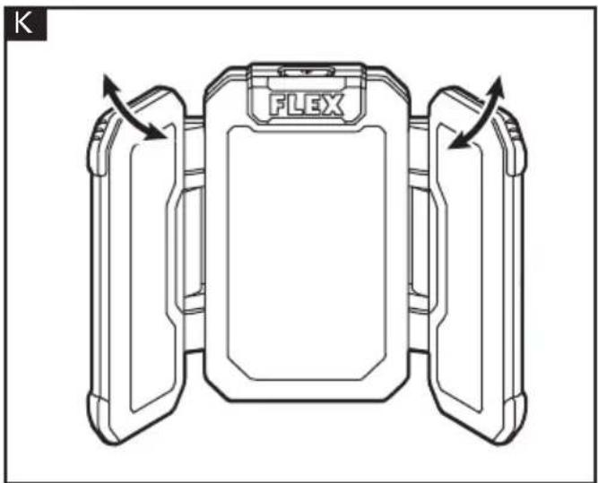
Auxiliary lights
The two auxiliary lights 16 can be pivoted up to 210° relative to the main light.
Pivot the auxiliary lights to a desired angle within the range. Do not force the auxiliary lights beyond the recommended range (see figure K).
Hooks

WARNING!
Only use the hooks to hang the light module when it is not attached to the tripod. Failure to heed this warning may result in injury or damage.
The light unit is equipped with two hooks 2. It can be carried or hung on a rope, nail, or a 2X4 piece of wood.
The hooks are permanently fixed to the light module and cannot be removed. The hooks can be folded for storage or pulled out and rotated separately (see figure L).
Adjusting the height

WARNING!
When adjusting the height of the tripod, hold the upper or lower extension tube with one hand and unlock the clamp with the other. If not held properly, the top portion of the tripod and the light module mounted to the tripod could descend rapidly and cause serious personal injury or property damage.

WARNING!
Keep everyone-helpers, bystanders, children, and animals-a safe distance from an extended tripod. Serious personal injury or property damage could occur if the tripod is tipped. Unless you are adjusting the tripod or mounting the light module onto it, keep a safe distance away from the tripod.
■ Unlock the upper 19 and/or lower clamp 21, extend the upper 18 and/or lower extension tubes 20 to the desired length.
■ Lock the clamps to prevent the tubes from moving during operation (see figure M).
USB port
The USB port 8 can be used to charge a cell phone or similar USB device (5 Volt DC, up to 2.1 A) when a battery is attached or the tripod light is connected to an AC power supply (see figure N).
NOTE: The USB port is not active all the time. Before connecting a USB device to the port, press the power-indicator button 9 and the power indicators 11 will light up. This activates the USB port 8 and a USB device can be connected and charged.
Power indicator
This tripod light is equipped with power indicators 11 that display the battery pack charge level on both sides of the carrying handle 12 (see figure N).
When you press the power-indicator button 9, the LEDs of the power indicator 11 will light up for 10 seconds (solid or flashing light). Refer to the table below to determine the battery charge level.
NOTE: If the power-indicator button 9 is pressed while the tripod is connected to AC power supply, all four LEDs of the power indicators will light up.
| Battery Pack Charge Level | Power Indicator Lights | Light Pattern |
| 75% - 100% | Solid | |
| 50% - 75% | Solid | |
| 25% - 50% | Solid | |
| 10% - 25% | Solid | |
| <10% | Flashing |
Low capacity warning
If one LED on the power indicator begins to flash, the battery pack charge is under 10% capacity and should be recharged. Unlike other types of battery packs, lithium-ion battery packs deliver fade-free power for their entire run time.
The light will not experience a slow, gradual loss of power as it is used. The power delivered to the light will drop quickly when the battery pack is at the end of its run time and needs to be charged.
When the battery pack is completely discharged or over-voltage, the power indicator will begin to display four flashing LEDs.
When this happens, turn the light off and charge the battery pack as needed.
Over-temperature warning
The battery circuitry also protects the battery pack from overheating. To protect the battery pack from damage and prolong its life, the battery pack circuitry will send a warning signal to the tool if the temperature becomes too high during use. The first and third LEDs on the power indicator will rapidly flash green to warn of the over-temperature condition. The battery pack will begin normal operation after it has cooled down.
Note: A significantly reduced run time after fully charging the battery pack indicates that the batteries are near the end of their usable life and must be replaced.
Cold weather operation
When the battery pack is very cold, the performance may be weakened. Place the battery pack in room temperature until it has warmed.
On/off switch

WARNING!
To reduce the risk of injury, do not look directly into the light when the light is on. The light can be turned on by either the On/Off switch 1 on the light module (see figure O) or the On/Off switch10 on the carrying handle of the tripod (see figure P). Both switches work identically.
The light has a three-stage brightness adjustment, providing different light intensities for your operation.
■ Press the On/Off switch to turn on the light in the maximum brightness stage.
■ Press the On/Off switch again to change to the medium brightness stage.
■ Press the On/Off switch the third time to change to the minimum brightness stage.
■ Press the fourth time to turn the light off.
Maintenance and care

WARNING!
Remove the battery before carrying out any work on the power tool.
If the external flexible cable or cord of this luminaire is damaged, it shall be replaced by a special cord or cord exclusively available from the manufacturer or his service agent.
Cleaning
■ Clean the power tool and grille in front of the vent slots regularly. Frequency of cleaning is dependent on the material and duration of use.
Spare parts and accessories
For other accessories, in particular tools and polishing aids, see the manufacturer's catalogues.
Exploded drawings and spare-part lists can be found on our homepage:
www.flex-tools.com
Disposal information

WARNING!
Render redundant power tools unusable:
- mains operated power tool by removing the power cord,
- battery operated power tool by removing the battery.

EU countries only
Do not throw electric power tools into the household waste!
In accordance with the European Directive 2012/19/EU on Waste Electrical and Electronic Equipment and transposition into national law used electric power tools must be collected separately and recycled in an environmentally friendly manner.

Raw material recovery instead of waste disposal.
Device, accessories and packaging should be recycled in an environmentally friendly manner. Plastic parts are identified for recycling according to material type.

WARNING!
Do not throw batteries into the household waste, fire or water. Do not open used batteries.
EU countries only:
In accordance with Directive 2006/66/EC defective or used batteries must be recycled.

NOTE
Please ask your dealer about disposal options!
CE-Declaration of conformity
We declare on our sole responsibility that the product described in "Technical specifications" conforms to the following standards or normative documents:
EN 60598 in accordance with the regulations of the directives 2014/30/EU, 2006/42/EC, 2011/65/EU.
Responsible for technical documents:
Peter Lameli Klaus Peter Weinper Technical Head Head of Quality
Department (QD)
Exemption from liability
The manufacturer and his representative are not liable for any damage and lost profit due to interruption in business caused by the product or by an unusable product.
The manufacturer and his representative are not liable for any damage which was caused by improper use of the product or by use of the product with products from other manufacturers.

Declaration of Conformity
We as the manufacturer: FLEX Elektrowerkzeuge GmbH, Business address: Bahnhofstr. 15, 71711 Steinheim, Germany
declare under our sole responsibility, that the product(s) described under „Technical specifications“ fulfills all the relevant provisions of The Supply of Machinery (Safety) Regulations S.I. 2008/1597 and also fulfills all the relevant provisions of the following UK Regulations:
Electromagnetic Compatibility Regulations S.I. 2016/1091, The Restriction of the Use of Certain Hazardous Substances in Electrical and Electronic Equipment Regulations
S.I. 2012/3032 and are manufactured in accordance with the following designated Standards:
BS EN IEC 60598-1:2021+A11:2022, BS EN 60598-2-4:2018, BS EN 62493:2015
Place of declaration: Steinheim, Germany. Responsible person: Peter Lameli, Technical Director - FLEX-Elektrowerkzeuge GmbH
Contact details for Great Britain: FLEX Power Tools Limited, Unit 8 Anglo Office Park, Lincoln Road, HP 12, 3RH Buckinghamshire, United Kingdom.

Peter Lameli Klaus Peter Weinper Technical Head Head of Quality Department
01.10.2022
Expandir/encurtar as pernas do tripé

AVISO!
Technical Head Head of Quality
Department (QD)
Peter Lameli Klaus Peter Weinper Technical Head Head of Quality Department
Peter Lameli Klaus Peter Weinper Technical Head Head of Quality Department
(QD)
Peter Lameli Klaus Peter Weinper Technical Head Head of Quality Department
(QD)
Comutator pornit/oprit (On/Off).

AVERTISMENT!
Technical Head Head of Quality
Department (QD)
Technical Head Head of Quality
Department (QD)
Toitelüliti (On/Off).

HOIATUS!
Peter Lameli Klaus Peter Weinper Technical Head Head of Quality Department
Technical Head Head of Quality
Department (QD)
Peter Lameli Klaus Peter Weinper Technical Head Head of Quality
Department (QD)
Peter Lameli Klaus Peter Weinper Technical Head Head of Quality
Department (QD)