
WT 10MP - Lawn mower HUSQVARNA - Free user manual and instructions
Find the device manual for free WT 10MP HUSQVARNA in PDF.
| Product type | Pressurized water tank |
| Brand | Husqvarna |
| Model | WT 10MP |
| Maximum fill capacity | 10 liters |
| Total capacity | 12.5 liters |
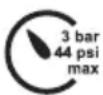
| Maximum spray pressure | 3 bar |
| Maximum operating temperature | 40 °C |
| Empty weight | 2.8 kg |
| Tank material | Polyethylene |
| Transport mode | Lateral |
| Residual quantity | Less than 0.07 liters |
| Pump | Integrated manual |
| Flexible hose | Included with quick coupling |
| Safety valve | Yes |
| Piston pressure gauge | Yes, with pressure indicator |
| Intended use | Water supply for dust binding (drills, concrete saws, grinders) |
| Maintenance | Lubrication of O-rings and cuff after 50 uses; cleaning of the filter |
| Safety | Do not exceed 3 bar; avoid freezing; use only original parts |
| Compliance | CE, UKCA |
Frequently Asked Questions - WT 10MP HUSQVARNA
User questions about WT 10MP HUSQVARNA
0 question about this device. Answer the ones you know or ask your own.
Ask a new question about this device
Download the instructions for your Lawn mower in PDF format for free! Find your manual WT 10MP - HUSQVARNA and take your electronic device back in hand. On this page are published all the documents necessary for the use of your device. WT 10MP by HUSQVARNA.
USER MANUAL WT 10MP HUSQVARNA
EN Operator's manual English 6
Husqvarna AB, SE-561 82 Huskvarna, Sweden
| Spare Parts رايغلا ع時期 резервни части | ||
| Náhradní díly Reservedele Ersatzteile | ||
| АвталлактикаPiezas de repuesto Varuosade | ||
| Varaosat Pièces de rechangeRezervni dijelovi | ||
| Alkatrészek Pezzi di ricambio Atsarginès detalès | ||
| Rezerves daļas Reserve-onderdelen Reservedeler | ||
| Części zamienne Peças sobressalentes Piese de schimb | ||
| запасные части | Náhradné diely | Rezervni deli |
| Резервни делови | Reservdelar | Yedek parçalar |
| Запасні частини | スペアパーツ | 备件 |
Husqvarna WT 10MP


 9 9 |  10 10 |
 11 12 11 12 |  |
  16 17 16 17 |  |
 18 19 18 19 |  |
 20 21 20 21 |  |
 24 26 24 26 | 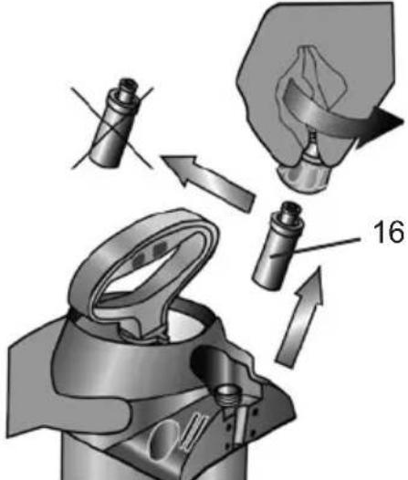 |
Welcome and congratulations

Read the manual carefully and make sure that you understand the instructions before you use the product. Keep the instructions for use in a safe place where they can be easily found.
The instructions for use are an integral part of the device and must be enclosed when the device is passed on.
WARNING: This product can be dangerous and cause serious injury or death to the operator or others. Be careful and use the product correctly.
Product description
The Husqvarna WT 10 MP is a pressurized water tank where the pressure is created by a manual pump device.
Intended use
Water pressure tanks WT 10MP are designed for supplying drills, concrete saws, grinders, etc. with water for suppressing dust. Do not use the product for other tasks. Do not use the product for storage of liquids, drinking water or as eyewash. The product must only be used by professional operators with experience.
Product liability
As referred to in the product liability laws, we are not liable for damages that our product causes if:
• the product is incorrectly repaired.
- the product is repaired with parts that are not from the manufacturer or not approved by the manufacturer.
- the product has an accessory that is not from the manufacturer or not approved by the manufacturer.
- the product is not repaired at an approved service center or by an approved authority.
Safety
Only trained, healthy and rested people may work with the device. You should not be under the influence of alcohol, drugs or medication.
Children and adolescents must not use the device
Keep the spraying devices safe from access to children.
Take precautions to prevent hazardous substances from being misused.
→ Accident risk!
Observe the information regarding personal protection equipment in the operator manual of the product used.


Avoid ignition sources in the environment.
Do not allow the device to remain under pressure and/or exposed directly to sunlight. Make certain the device is not heated beyond the maximum operating temperature. ( → Table 1).
Protect the device from frost and ammonia.
There is a risk of slipping or tripping on smooth or wet surfaces, snow, ice, on slopes and on uneven terrain.
Keep the work area tidy and well lit.
Repairs and modifications to the device are not permitted.
Have damaged parts or parts that do not work properly repaired immediately by our customer service department or by service partners authorized by us.
The effect of the safety valve must not be bypassed or made inoperative.
→ Explosion hazard!
Use only original spare and accessory parts.
We cannot assume any liability resulting from the use of third-party parts.
Use only the built in hand pump to pressurize the water tank. When pumping, always observe the pressure gauge to ensure the maximum spraying pressure is not exceeded ( → Table 1). All excess pressure must be released from the device before filling, after use, before carrying out maintenance work, on work breaks, and before placing it in storage.
Points to note when transporting the device: Transport the device in such a way that it is protected against damage and tipping. All excess pressure must be released from the device.
→ Explosion hazard!
CE
This product is in compliance with applicable EC directives.
UK CA
This product conforms to the applicable UK regulations
Note: Other symbols/decals on the product refer to certification requirements for some markets.

You will find the illustrations referred to above in the pages 3 – 5 of these instructions for use.
Scope of delivery
Tank [1] with pump [2], hose [4], and Instructions for Use [5]. (Fig. 1)
Technical data
| Type of device WT 10MP | |
| Max. filling amount 10 l (2.64 gal) | |
| Total contents 12.5 l (3.3 gal) | |
| Max. spraying pressure 3 bar (43.5 psi) | |
| Max. operating temperature 40 °C (104 °F) | |
| Weight when empty 2.8 kg (6.16 lb) | |
| Material of tank polyethylene | |
| Where device is carried on the side | |
| Technical residual quantity <0.07 l (< 0.02 gal) | |
Table 1
Assembly
- Push the tube [4] into the fixture [10] and secure it with the cap nut. (Fig. 3)
Checks
Visual inspection: Are tank [1], pump [2] and hose [4] and piston pressure gauge [16] undamaged? (Fig. 1)
May special attention to the connections between the tank – hose and hose – plug-in coupling and to the condition of the pump thread.
No leaks: Pump up the empty device to 2 bar (29 psi) (Fig. 11).
▶ The pressure must not decrease more than 0.5 bar (7.25 psi) within 30 minutes.
Function: Pull up the piston pressure gauge [16] (Fig. 5)
▶ The pressure must dissipate.

Check the device regularly and after a longer period of non-use, e.g. a winter break. Have damaged parts or parts that do not work properly repaired immediately by our by a Husqvarna service team
Preparation

Observe the instructions in the section entitled „Safety“.
The device must be in an upright position.
If filling the tank from a water line, ensure that the line or a hose does not project into the tank.
- Pull up the red piston pressure gauge [16] until the tank is depressurized. (Fig. 5)
- Press the piston rod with handle [13] down and turn it counterclockwise.
▶ The piston rod with handle is locked. (Fig. 6)
- Unscrew the pump [2] from the tank. (Fig. 7)
- Add the liquid to the tank [1]. (Fig. 8)
- Check the filling level with the scale [35] on the tank. (Fig. 8)
- Screw the pump [2] into the tank. (Fig. 9)
-
Press the piston rod with handle [13] down and turn it clockwise.
▶ The piston rod with handle is unlocked. (Fig. 10) -
Create the desired pressure in the tank. (Fig. 11)
The maximum pressure should not exceed 3 bar (43,5 psi) (red line on the piston pressure gauge, Fig. 11). If the maximum pressure is exceeded, the safety valve will engage and release the excess pressure.
- Press the piston rod with handle [13] down and turn it counterclockwise. (Fig. 6)
▶ The piston rod with handle is locked.
Use

Observe the instructions in the section entitled "Safety".
-
Connect the plug-in coupling [15] of the water pressure tank with the plug-in nipple on your device [29]. (Fig. 12)
-
Activate the ball valve [30]. (Fig. 12)
▶ The liquid starts to be supplied.
The amount of liquid can be regulated via the ball valve [30] on the device (e.g. drill).
-
If the pressure drops below 1 bar (14.5 psi), min. 0.5 bar (7.25 psi), pump again. (Fig. 11)
-
If the tank is empty, refill. ( → See chapter entitled “Preparation”)
After Usage

Observe the instructions in the section entitled "Safety". Never leave liquid in the device.
- Hold the plug-in coupling [15] and pull its outer ring. (Fig. 12)
▶ The plug-in coupling [15] is disconnected from the plug-in nipple [29] on the device.
-
Pull up the red piston pressure gauge [16] until the tank is depressurized. (Fig. 5)
-
Lock the piston rod with handle [13]. (Fig. 6)
-
Unscrew the pump [2] from the tank and empty the tank. (Fig. 7)
-
Wipe off the device with a moist cloth.
-
For drying and storing the device, keep the tank [1] and pump [2] separate in a dry place protected from sunlight and freezing temperatures (Fig. 16).
Care and maintenance

Observe the instructions in the section entitled "Safety".
After using the device 50 times or at least once a year:
- Unscrew the pump [2] from the tank. (Fig. 7)
- Dismantle the pump [2].
a) Unlock the piston rod with handle [13]. (Fig. 17)
b) Pull the piston rod with handle [13] out of the cylinder tube up to the stop and turn it counterclockwise (Fig. 17)
c) Disconnect the piston rod with handle [13] and the cylinder tube [2]. (Fig. 17)
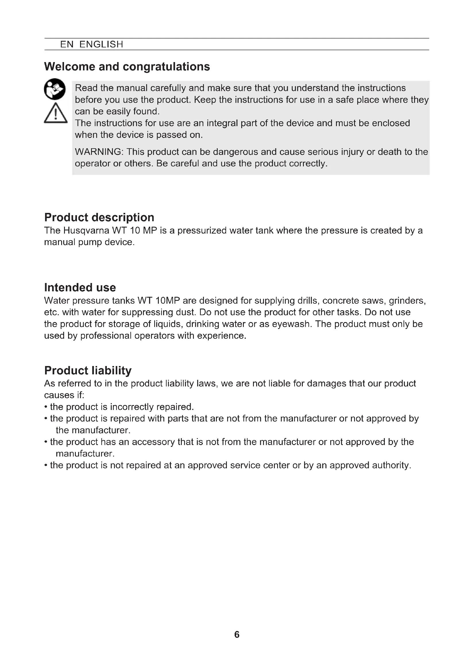
- Grease the O-ring [19] and the diaphragm [20]. (Fig. 18)
- Assemble the pump.
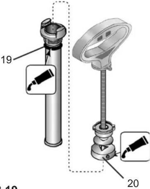
a) Push the piston rod with handle [13] into the cylinder tube. (Fig. 20)
b) Hold the cylinder tube [2] and strongly press in the guiding plug [14] with your thumb. (Fig. 20)
c) Pull the piston rod with handle [13] up to the stop down and turn it clockwise (Fig. 20)
▶ The guiding plug [14] snaps in.
- Lock the piston rod with handle [13] and screw the pump [2] into the tank [1]. (Fig. 9)
• Take the hose [4] with the discharge filter [34] out of the tank and clean the discharge filter under running water. (Fig. 24)

Observe the legal requirements of your country for accident prevention and check the device in regular intervals.
Unless otherwise specified, we recommend that an expert carries out an external test every 2 years and an internal test every 5 years as well as a strength test every 10 years.
Faults

Use only original spare and accessory parts.
| Fault Cause Remedy | ||
| No pressure builds up in the device | The pump is not screwed on tightly. | Screw the pump on tightly. |
| O-ring [19] on the pump is faulty. | Replace the O-ring (Fig. 19). | |
| Diaphragm [20] is defective. | Replace the diaphragm (Fig. 19). | |
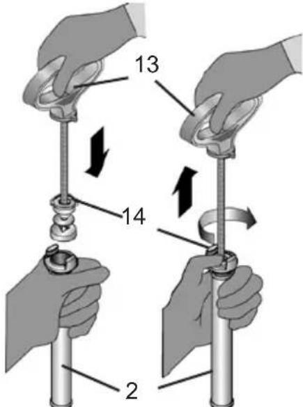
| Liquid flows out of the pump | Valve disc [23] dirty of defective. | Clean or replace the valve disc (Fig. 21). |
| No tank pressure indication on the piston pressure gauge, Safety valves blow off too early. | Piston pressure gauge [16] is defective. | Replace the piston pressure gauge (Fig. 26). |
The data and illustrations in these instructions for use are for orientation only and not binding in any way. The manufacturer reserves the right to make changes or improvements to the products if these are considered appropriate without having to notify customers owning a similar model about this fact.
CE
EU Declaration of Conformity
We, Husqvarna AB, SE 561 82 Huskvarna, SWEDEN, Tel. +46 36 146500 declare on our sole responsibility that the product:
| Description Pressurized Water Tank | |
| Brand HUSQVARNA | |
| Type / Model WT 10 MP | |
| Identification Manufacture | dating from 2022 and onwards, in form Month and Year, MMYY |
complies fully with the following EU directives and regulations:
| Directive/Regulation Description | |
| 2006/42/EC „relating to machinery“ | |
and that the following standards and/or technical specifications are applied; EN ISO 12100:2010
Partille, 2022-11-30

Fredrik Sandinge
R&D Director, Concrete Sawing & Drilling Equipment
Husqvarna AB, Construction Division
Responsible for technical documentation
UK Declaration of Conformity
We, Husqvarna AB, SE 561 82 Huskvarna, SWEDEN, Tel. +46 36 146500 declare on our sole responsibility that the product:
| Description Pressurized Water Tank | |
| Brand HUSQVARNA | |
| Type / Model WT 10 MP | |
| Identification Manufacture | dating from 2022 and onwards, in form Month and Year, MMYY |
complies fully with the following UK regulations:
| The Supply of Machinery (Safety) Regulations 2008 |
and that the following standards and/or technical specifications are applied; EN ISO 12100:2010
Partille, 2022-11-30

Fredrik Sandinge
R&D Director, Concrete Sawing & Drilling Equipment Husqvarna AB, Construction Division
Responsible for technical documentation
UK Importer: Husqvarna UK Ltd Preston Road, Co. Durham DL5 6UP

R&D Director, Concrete Sawing & Drilling Equipment Husqvarna AB, Construction Division
R&D Director, Concrete Sawing & Drilling Equipment
Husqvarna AB, Construction Division
R&D Director, Concrete Sawing & Drilling Equipment
Husqvarna AB, Construction Division
R&D Director, Concrete Sawing & Drilling Equipment
Husqvarna AB, Construction Division
Fredrik Sandinge
R&D Director, Concrete Sawing & Drilling Equipment
Husqvarna AB, Construction Division
R&D Director, Concrete Sawing & Drilling Equipment
Husqvarna AB, Construction Division
R&D Director, Concrete Sawing & Drilling Equipment
Husqvarna AB, Construction Division
R&D Director, Concrete Sawing & Drilling Equipment
Husqvarna AB, Construction Division
R&D Director, Concrete Sawing & Drilling Equipment
Husqvarna AB, Construction Division
R&D Director, Concrete Sawing & Drilling Equipment
Husqvarna AB, Construction Division
Responsable de la documentation technique
Čestitamo

Pročitajte upute za uporabu prije prvog pokretanja uređaja!
R&D Director, Concrete Sawing & Drilling Equipment
Husqvarna AB, Construction Division
R&D Director, Concrete Sawing & Drilling Equipment
Husqvarna AB, Construction Division
R&D Director, Concrete Sawing & Drilling Equipment
Husqvarna AB, Construction Division
R&D Director, Concrete Sawing & Drilling Equipment
Husqvarna AB, Construction Division
R&D Director, Concrete Sawing & Drilling Equipment
Husqvarna AB, Construction Division
▶ De pomphandgreep is vergrendeld. (afb. 6).
R&D Director, Concrete Sawing & Drilling Equipment
Husqvarna AB, Construction Division
R&D Director, Concrete Sawing & Drilling Equipment
Husqvarna AB, Construction Division
R&D Director, Concrete Sawing & Drilling Equipment
Husqvarna AB, Construction Division
R&D Director, Concrete Sawing & Drilling Equipment
Husqvarna AB, Construction Division
R&D Director, Concrete Sawing & Drilling Equipment
Husqvarna AB, Construction Division
R&D Director, Concrete Sawing & Drilling Equipment
Husqvarna AB, Construction Division
R&D Director, Concrete Sawing & Drilling Equipment
Husqvarna AB, Construction Division
R&D Director, Concrete Sawing & Drilling Equipment
Husqvarna AB, Construction Division
R&D Director, Concrete Sawing & Drilling Equipment
Husqvarna AB, Construction Division
R&D Director, Concrete Sawing & Drilling Equipment
Husqvarna AB, Construction Division
Fredrik Sandinge
R&D Director, Concrete Sawing & Drilling Equipment
Husqvarna AB, Construction Division
R&D Director, Concrete Sawing & Drilling Equipment
Husqvarna AB, Construction Division
R&D Director, Concrete Sawing & Drilling Equipment
Husqvarna AB, Construction Division
技術文書の責任者
欢迎使用本产品

使用本设备前请阅读本使用说明书!
将使用说明书存放在容易找到的安全之处。
R&D Director, Concrete Sawing & Drilling Equipment
Husqvarna AB, Construction Division
对本技术文档负责
Husqvarna®
www.husqvarnaconstruction.com
Original instructions


Brand : HUSQVARNA
Model : WT 10MP
Category : Lawn mower