
IR Micro Office DALI2 - Motion detector STEINEL - Free user manual and instructions
Find the device manual for free IR Micro Office DALI2 STEINEL in PDF.
| Product type | Passive infrared (PIR) motion detector with DALI-2 control and Bluetooth Mesh |
| Brand | Steinel |
| Model | IR Micro Office DALI2 |
| Variants | Surface-mount (AP), flush-mount (UP), ceiling (DE) |
| Dimensions (AP) | Not specified in the manual (estimated: diameter ~100 mm, height ~50 mm) |
| Weight | Not specified (estimated: ~150 g) |
| Power supply | 220-240 V~, 50/60 Hz |
| Standby consumption | 0.4 W (without electronic ballast) |
| DALI interface | 2-wire control line, single master, 40 mA max (per IEC 62386-101) |
| Max supply current | 250 mA |
| Detection angle | 360° |
| Motion detection range (tangential) | 6 x 6 m (height 2.8 m) |
| Presence detection range (radial) | 4 x 4 m (height 2.8 m) |
| Optimal mounting height | 2.8 m |
| Twilight threshold | 2 - 1000 lux (adjustable), daylight mode (∞) |
| Main lighting time delay | 5 s to 60 min (adjustable) |
| Protection rating | IP20 (indoor) |
| Operating temperature | 0 °C to +40 °C |
| Bluetooth frequency | 2.4 - 2.48 GHz |
| Bluetooth transmission power | 10 dBm (10 mW max) |
| Main functions | Automatic/semi-automatic mode, constant light control, base lighting, teach-in, presentation mode, detection zone limitation, Bluetooth grouping |
| Button input (S) | Yes, for manual control (On/Off, dimming, scenes) |
| Configuration | Via Steinel Connect app (Bluetooth Mesh) |
| Cleaning and maintenance | Clean dry with a soft cloth without detergent |
| Safety | Installation by a qualified professional, compliance with electrical standards (e.g., NF C 15-100) |
| Manufacturer warranty | 5 years |
Frequently Asked Questions - IR Micro Office DALI2 STEINEL
User questions about IR Micro Office DALI2 STEINEL
0 question about this device. Answer the ones you know or ask your own.
Ask a new question about this device
Download the instructions for your Motion detector in PDF format for free! Find your manual IR Micro Office DALI2 - STEINEL and take your electronic device back in hand. On this page are published all the documents necessary for the use of your device. IR Micro Office DALI2 by STEINEL.
USER MANUAL IR Micro Office DALI2 STEINEL
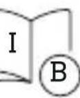
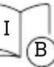
B = Sensor (Application Controller)
C =Taster
Application Controller / Broadcast.
- About this document 44
- General safety precautions 44
- System description 45
- Electrical connection 54
- Installation 56
- Function 70
- Cleaning and maintenance 78
- Disposal 79
- Conformity 79
- Manufacturer's warranty 80
- Technical specifications 81
- Troubleshooting 82
1. About this document
- Under copyright. Reproduction either in whole or in part only with our consent.
- Subject to change in the interest of technical progress.

Hazard warning!
Warning of hazards from electricity!

Warning of hazards from water!
2. General safety precautions

Failure to observe these operating instructions presents hazards!
These instructions contain important information on the safe use of this product. Particular attention is drawn to potential hazards. Failure to observe this information may lead to death or serious injuries.
- Read instructions carefully.
- Follow safety advice.
-
Keep instructions within easy reach.
-
Working with electrical current may produce hazardous situations. Touching live parts can result in electrical shock, burns or death.
- Work on mains voltage must only be performed by qualified, skilled personnel.
- National wiring regulations and electrical operating conditions must be observed (e.g. DE: VDE 0100, AT: ÖVE-ÖNORM E8001-1, CH: SEV 1000).
- Only use genuine replacement parts.
- Repairs must only be carried out by companies qualified to do so.
3. System description
Proper use
- Sensor for indoor ceiling mounting.
Operating principle
- The integrated infrared sensor detects the heat radiated from moving objects (e.g. people, animals). The heat detected in this way is converted electronically into a signal that switches the LED floodlight ON automatically.
- The most reliable way of detecting motion is to install the unit with the sensor aimed across the direction in which a person would walk.
- Motion detection reach is restricted when the unit is approached head on.
- Obstacles (such as trees, walls or panes of glass) may restrict or prevent the detection of movement.
- Sudden fluctuations in temperature as a result of changes in weather are not distinguished from sources of heat.
Certification:
This product is certified according to IEC 62386-103 as a single-master application controller. Its DALI 2 certification therefore only covers applications in which only DALI electronic ballasts (control gear) are connected to the DALI bus.
IR Micro Office DALI-2 APC AP: Surface-mounted variant
IR Micro Office DALI-2 APC UP: Concealed variant
IR Micro Office DALI-2 APC DE: Variant for ceiling installation
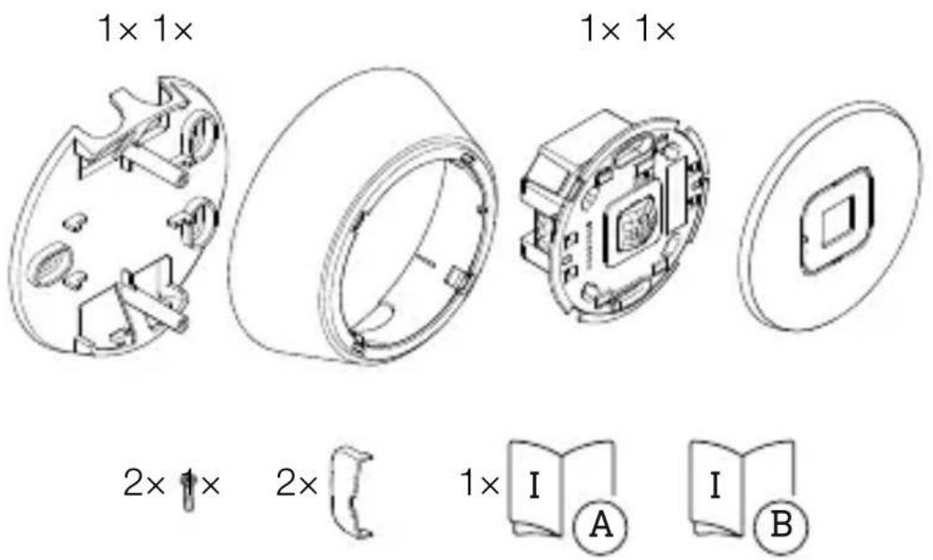
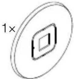
Scope of delivery - IR Micro Office DALI-2 APC AP
3.1
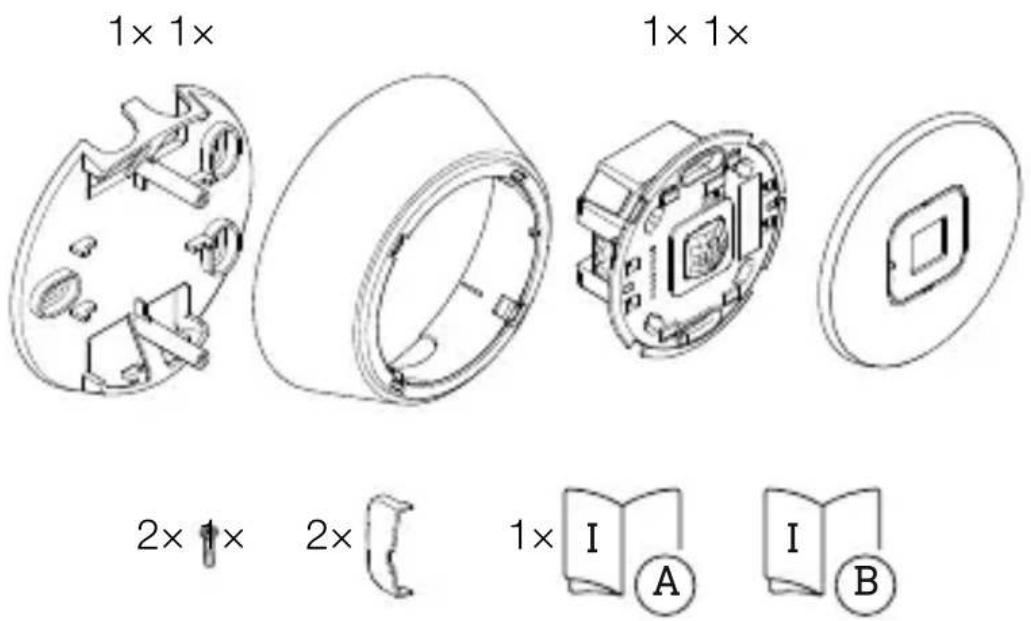
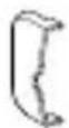
- 1 ceiling bracket
-1frame - 1 sensor module
-1cover - 2 small screws
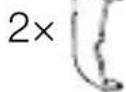
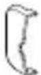
- 2 shrouds
- 1 safety data sheet
- 1 quick-start guide
Scope of delivery - IR Micro Office DALI-2 APC UP
3.2


- 1 sensor module
-1cover - 2 shrouds
- 1 safety data sheet
- 1 quick-start guide
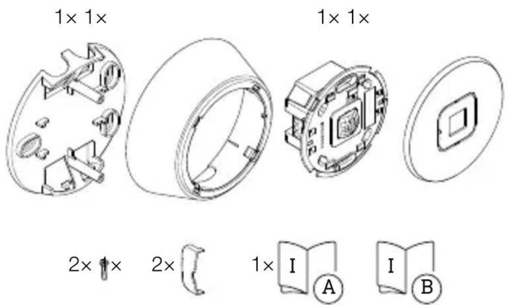
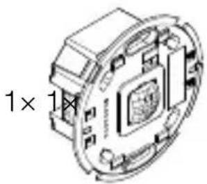
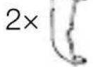
Scope of delivery - IR Micro Office DALI-2 APC DE
3.3
1x

1x

2 ×

1x

1x
- 1 sensor module
-1cover - 2 shrouds
- 1 safety data sheet
- 1 quick-start guide
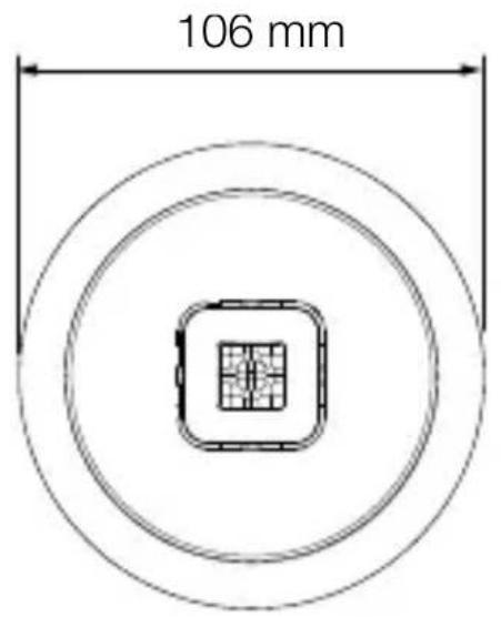
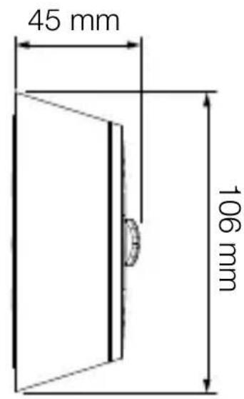
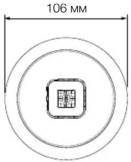
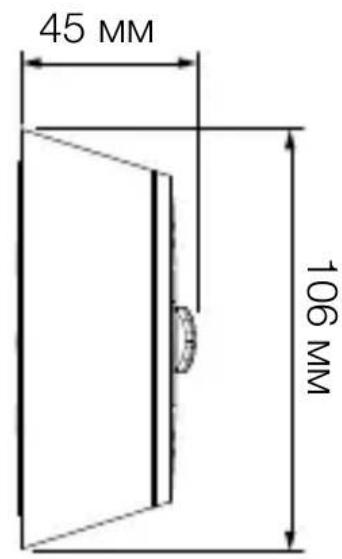
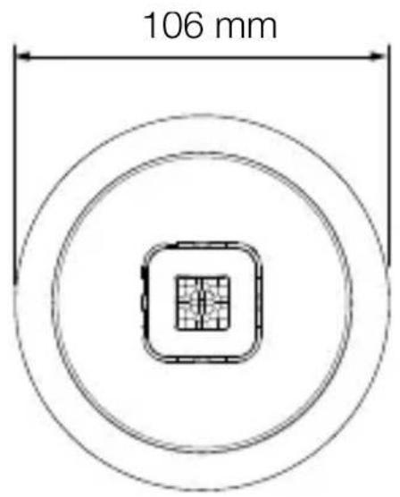
Product dimensions - IR Micro Office DALI-2 APC AP
3.4


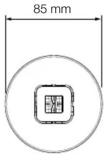
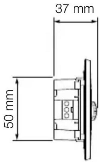
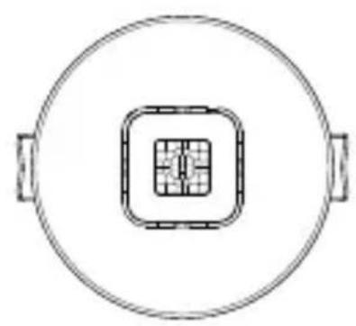
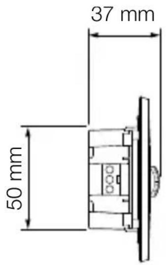
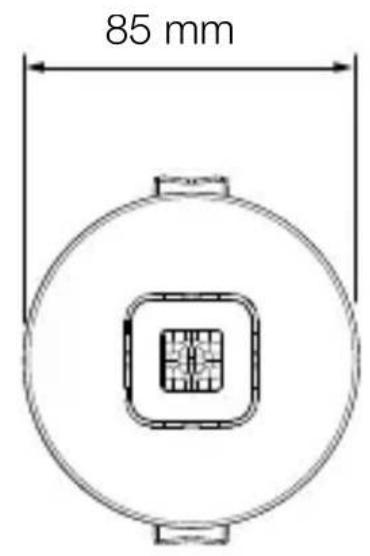
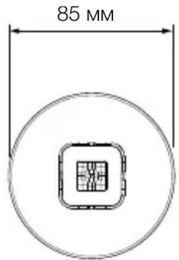
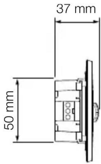
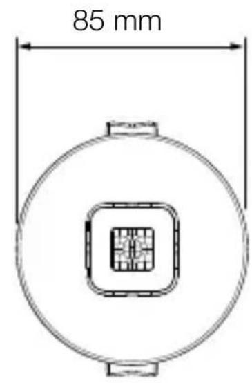
Product dimensions - IR Micro Office DALI-2 APC UP
3.5
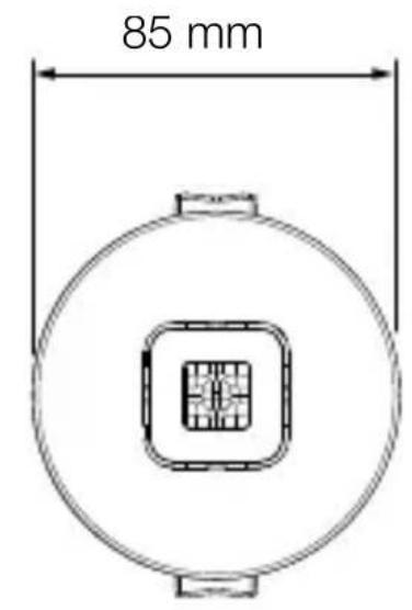
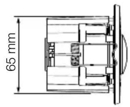
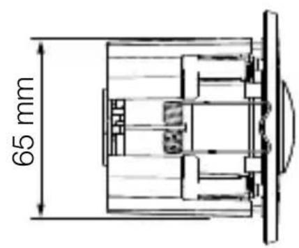
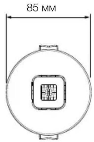
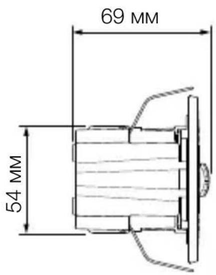
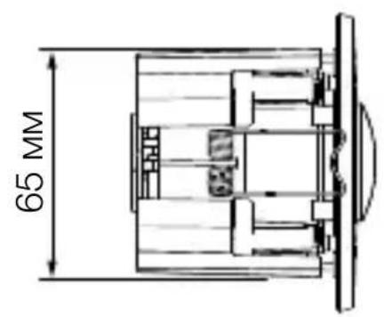
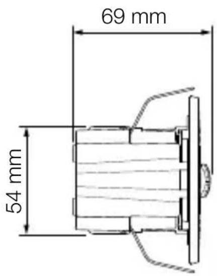
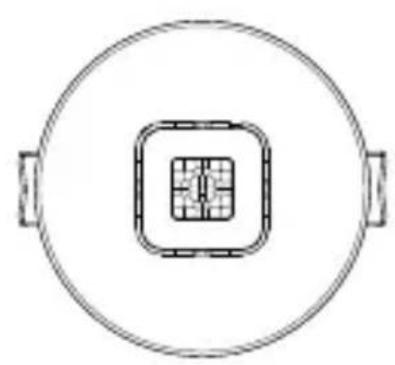
Product dimensions - IR Micro Office DALI-2 APC DE
3.6

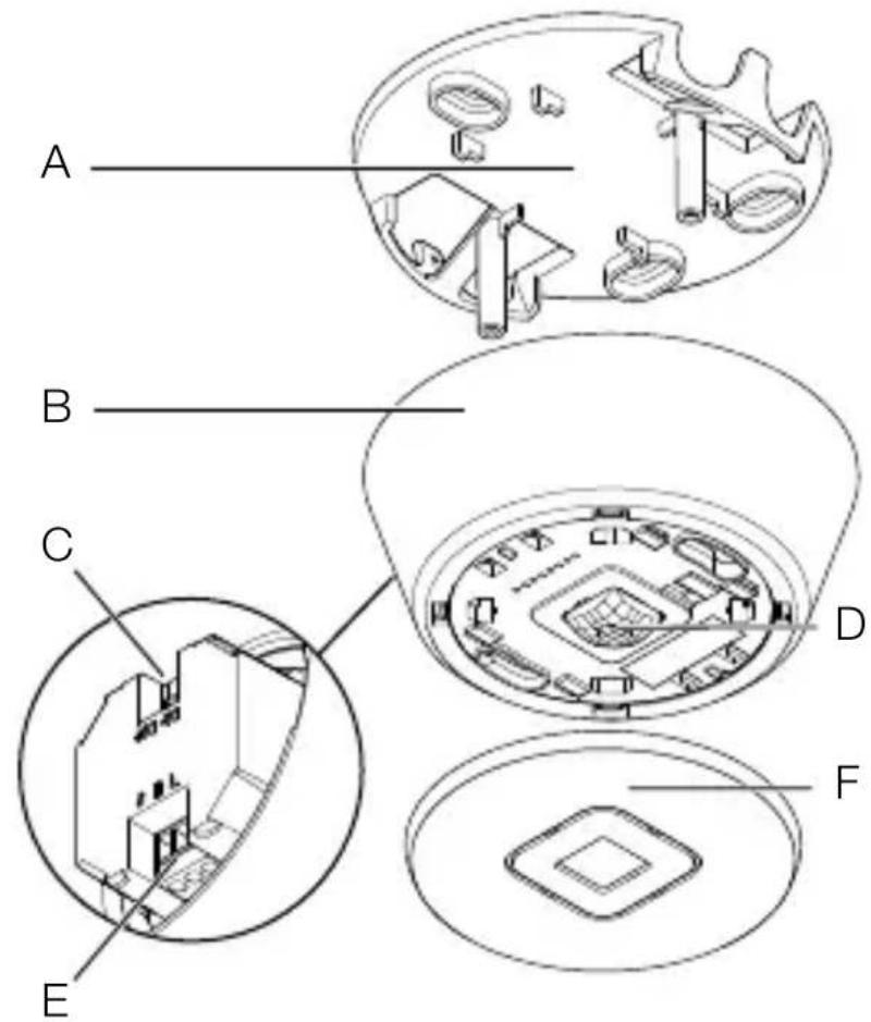
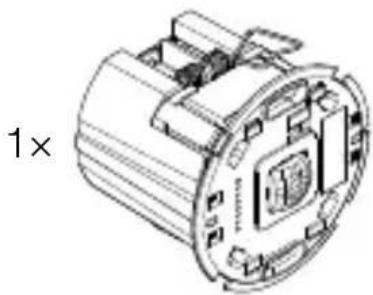
Device overview - IR Micro Office DALI-2 APC AP
3.7

A Ceiling bracket
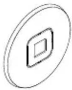
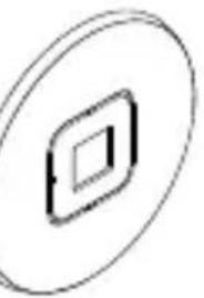
B Frame
C DALI-2 connection
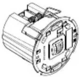
D Sensor module
E Electrical connection
F Abdteckung
Device overview - IR Micro Office DALI-2 APC UP
3.8
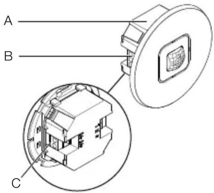
A Sensor module
B Electrical connection
C DALI-2 connection
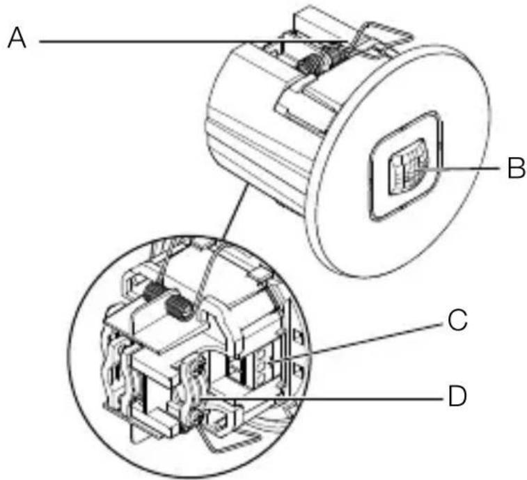
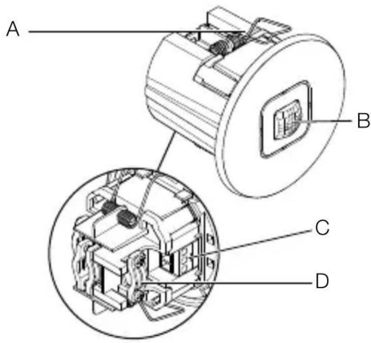
Device overview - IR Micro Office DALI-2 APC DE
3.9
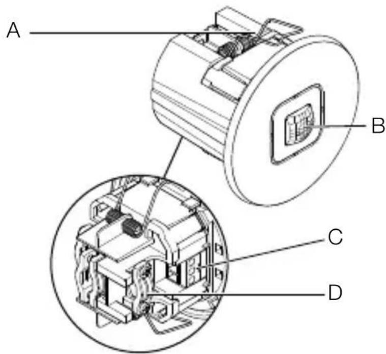
A Clip
B Sensor module
C Electrical connection
D Strain relief
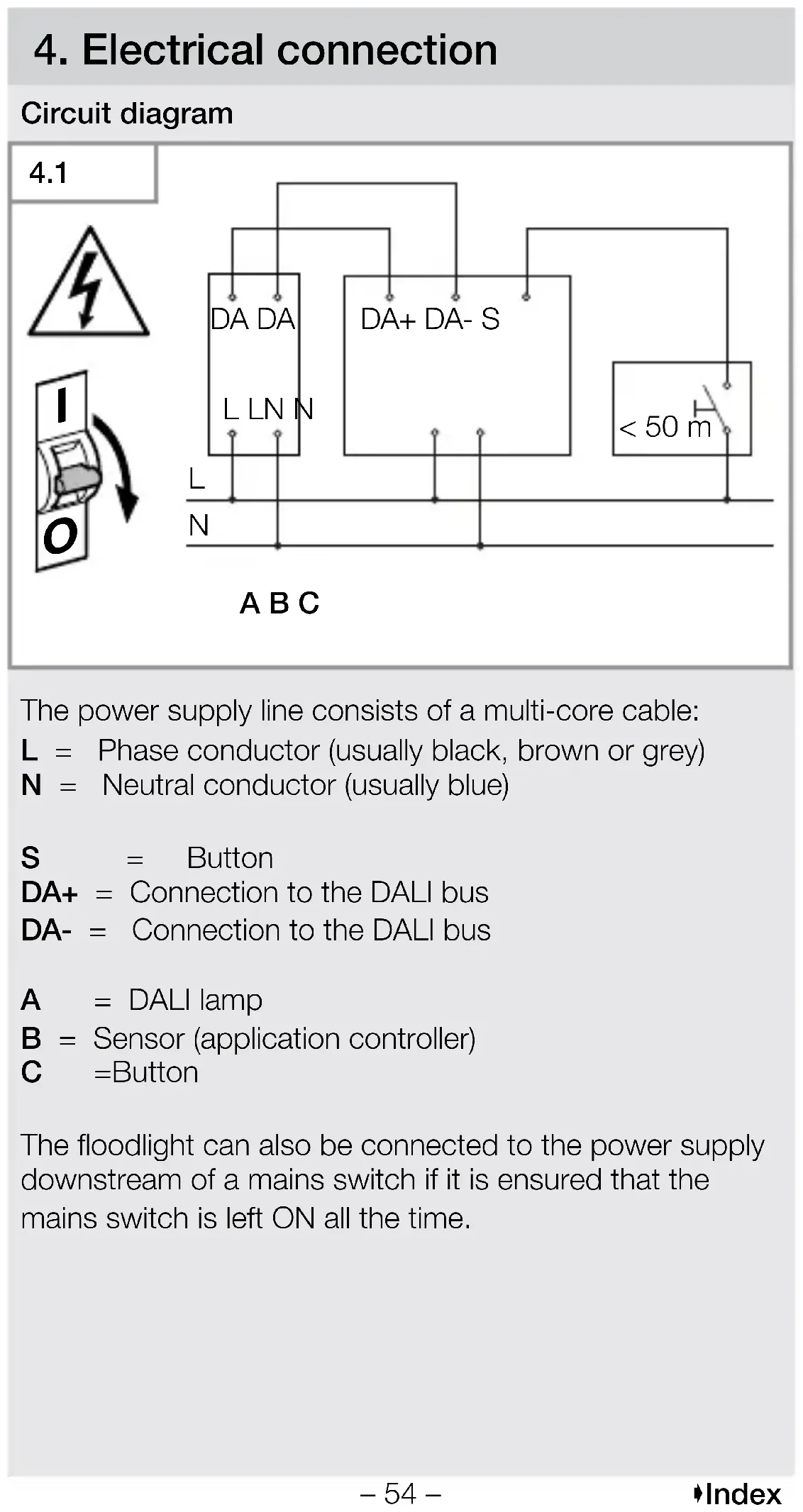
4. Electrical connection
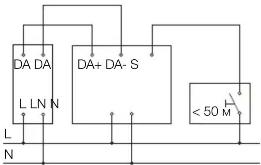
Circuit diagram
4.1

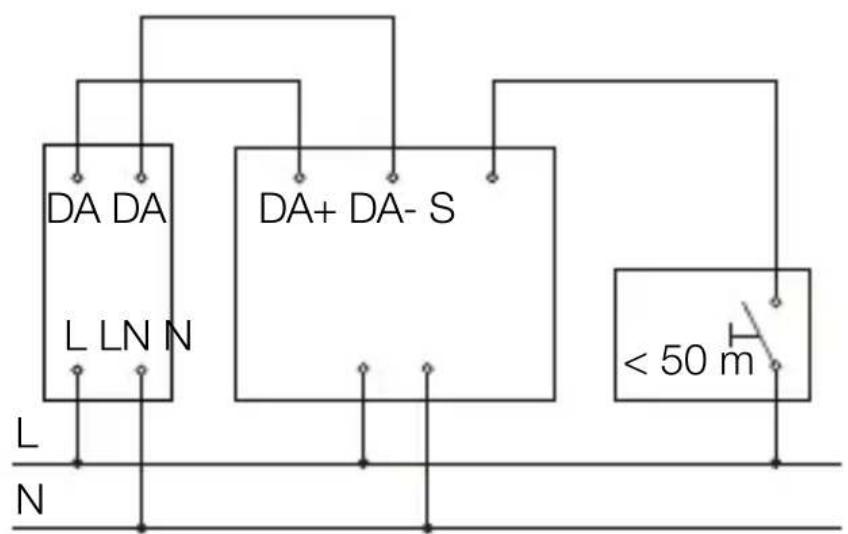
ABC
The power supply line consists of a multi-core cable:
L = Phase conductor (usually black, brown or grey)
N = Neutral conductor (usually blue)
S = Button
DA+ = Connection to the DALI bus
DA- = Connection to the DALI bus
A = DALI lamp
B = Sensor (application controller)
C =Button
The floodlight can also be connected to the power supply downstream of a mains switch if it is ensured that the mains switch is left ON all the time.
The following applies to the wiring of the sensor: According to VDE 0100 520 Section 6, a multi-core cable containing both the mains voltage lines and the control lines (e.g. NYM 5 × 1.5 ) can be used for wiring between the DALI electronic ballast (control gear) and the DALI application controller.
The maximum cable length between the DALI application controller and the DALI electronic ballast (control gear) should not exceed 300m (at 1.5mm^2 ). After installation and switching on, the LED of the sensor lights up for 10 seconds.
5. Installation
Hazard from electrical power.
Touching live parts can result in electrical shock, burns or death.
- Switch OFF power and interrupt power supply.
- Using a voltage tester, check to make sure that the power supply is disconnected.
- Make sure power supply remains interrupted.
Risk of damage to property!
Mixing up connection leads may produce a short circuit.
- Identify connection leads.
- Connect the leads correctly.
Preparing for installation
- Check all components for damage. Do not use the floodlight if it is damaged.
-
Select an appropriate site to install the product.
-
Take reach into consideration.
- Take reach and motion detection into consideration.
Vibration-free. - No obstacles in detection zone.
- Not in explosive atmospheres.
- Not on normally flammable surfaces.
-At least 50 cm away from other sensors.
-Cable length between sensor and button < 50m
Range
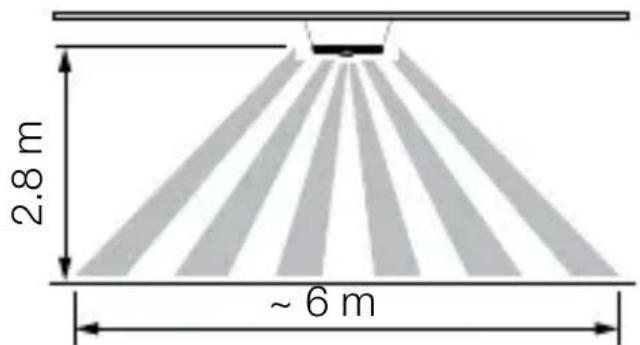
5.1
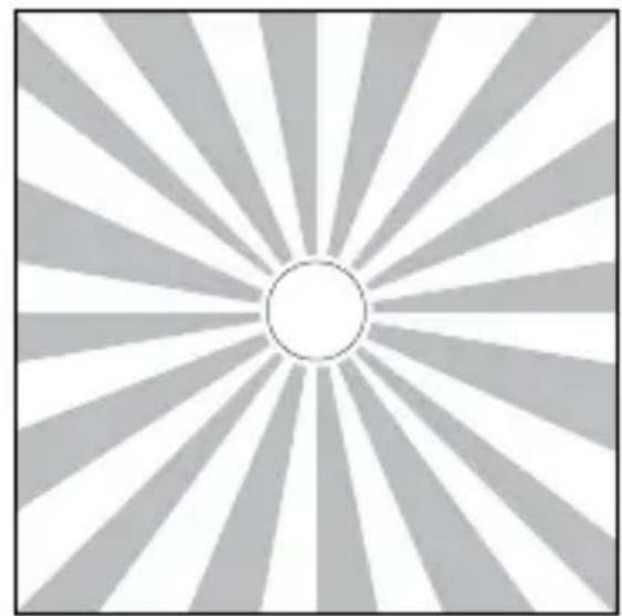
Motion detection
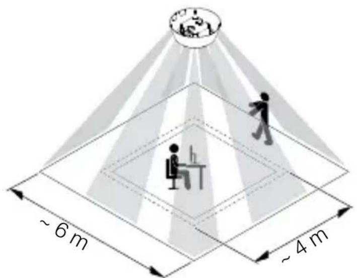
5.2
Assembly steps - IR Micro Office DALI-2 APC AP
5.3

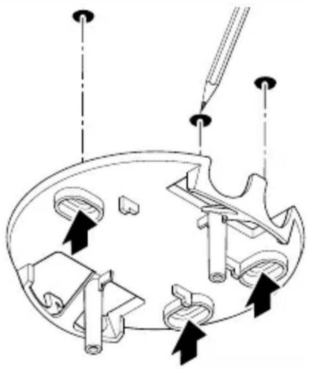
- Ensure that the power supply is switched off.
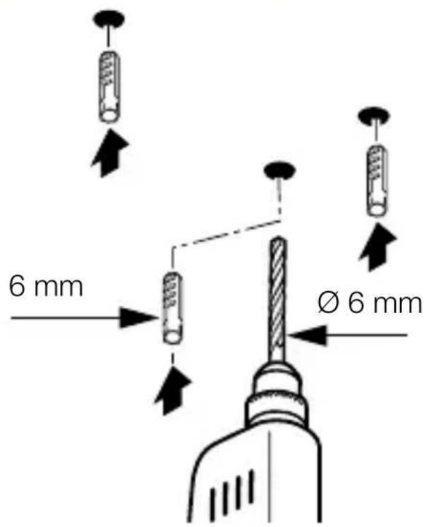
- Mark drill holes.
5.4

- Drill holes (Ø 6 mm) and fit wall plugs.
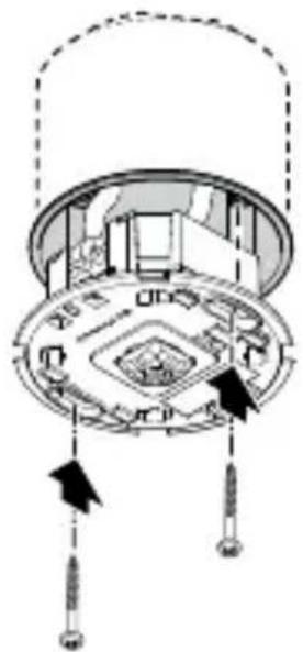
5.5
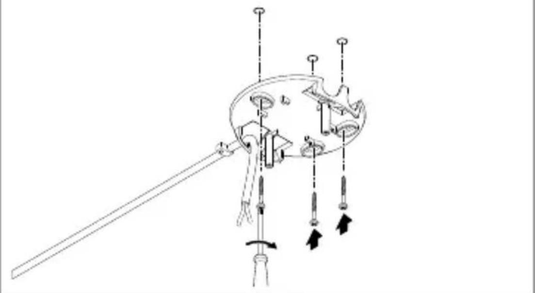
- Pull the cable through the opening.
- Screw on the ceiling bracket.
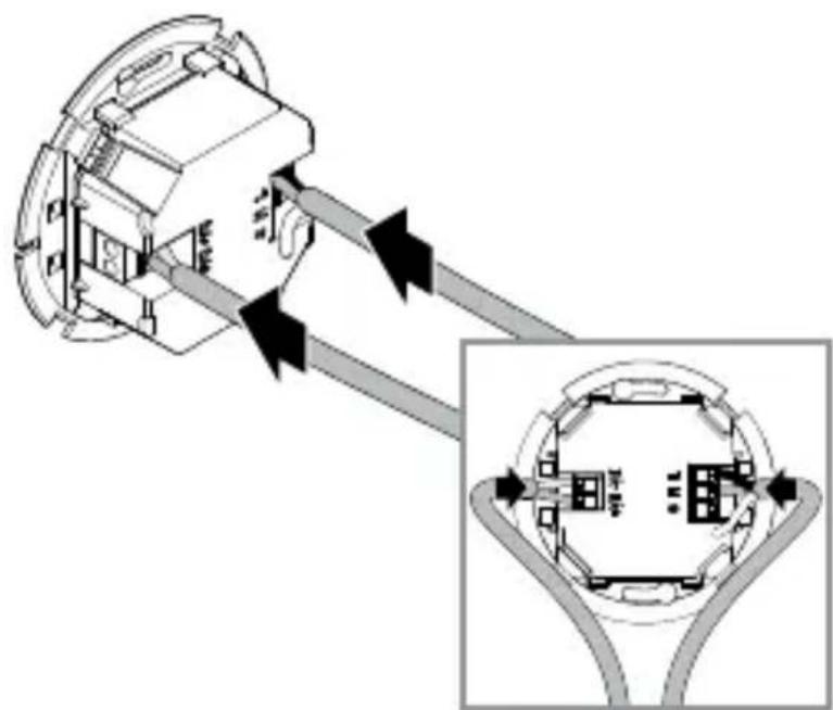
5.6
- Connect the power cable and DALI bus according to the circuit diagram.
"4. Electrical connection"
5.7
- Screw on the sensor module.
5.8
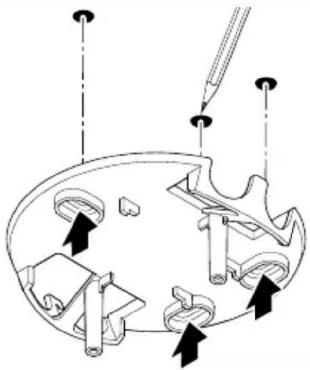
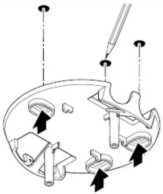
- Break out the flashes from of the frame as needed. Pay attention to the orientation lug of the sensor module!
5.9
- Fit the frame in the correct orientation. Note the notches.
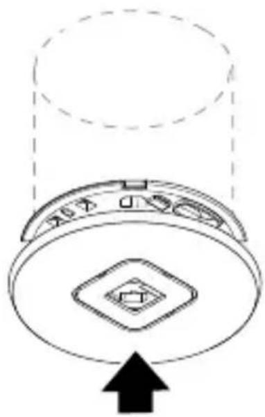
5.10
- Fit the cover.
5.11

- Switch ON power supply.
- Set the functions.
"6. Function"
Assembly steps - IR Micro Office DALI-2 APC UP
5.12


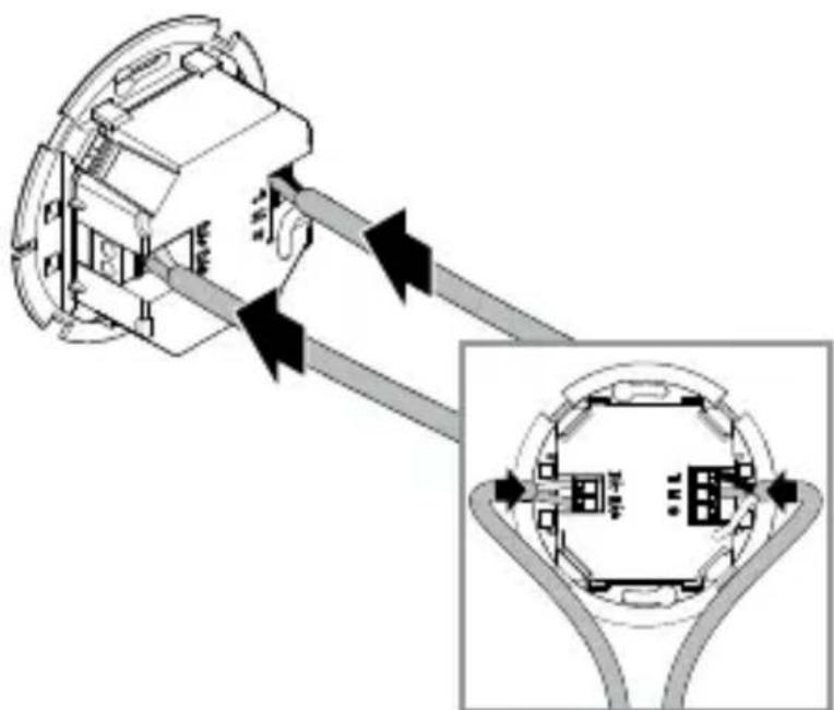
- Ensure that the power supply is switched off.
- Connect the power cable and DALI bus according to the circuit diagram.
"4. Electrical connection"
5.13
- Screw on the sensor module.
5.14
- Fit the cover.
5.15

- Switch ON power supply.
- Set the functions.
"6. Function"
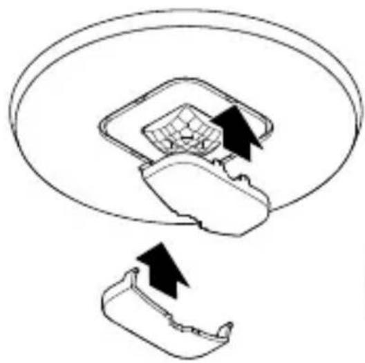
Assembly steps - IR Micro Office DALI-2 APC DE
5.16


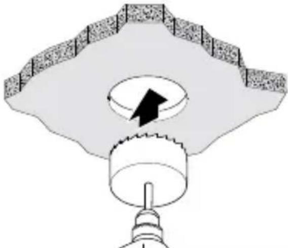
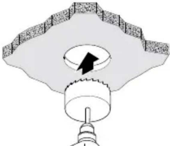
- Ensure that the power supply is switched off.
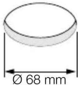
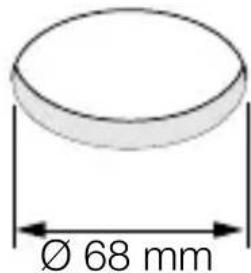
- Drill a 68 mm hole in the subceiling.
5.17
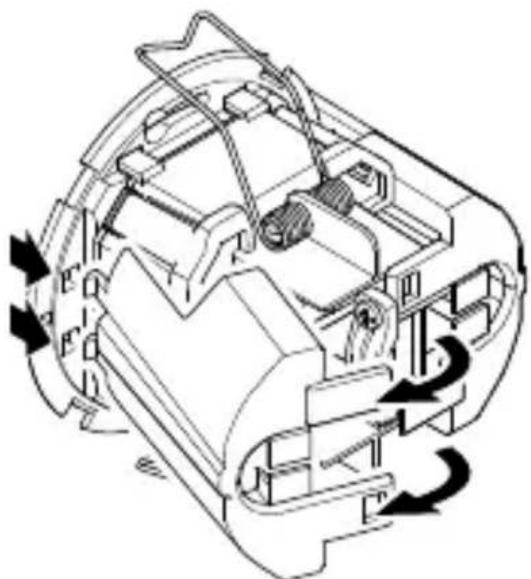
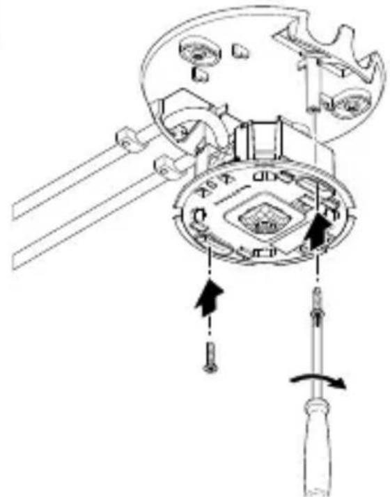
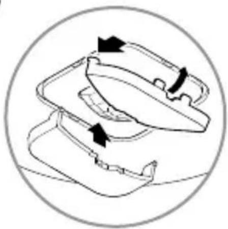
- Open the housing.
5.18
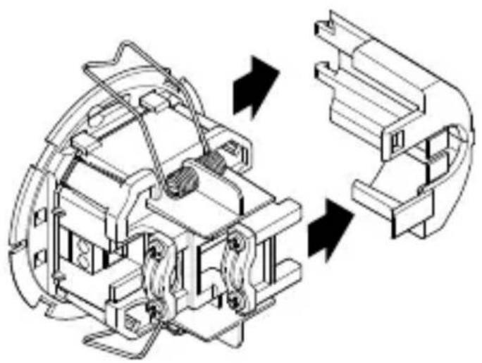
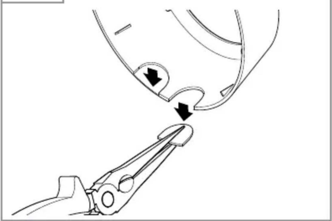
- Remove the side panel.
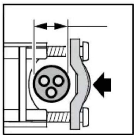
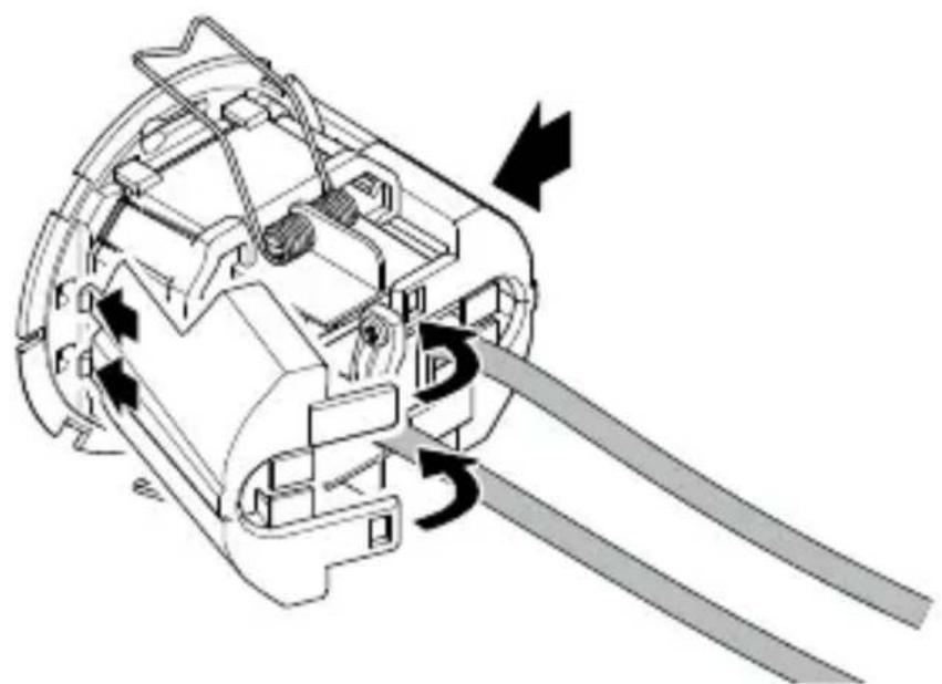
5.19


- Clampable cable diameter 7.6 mm - 14.5 mm:
Large cable diameter (left).
Attach the strain relief clamp as shown on the left.
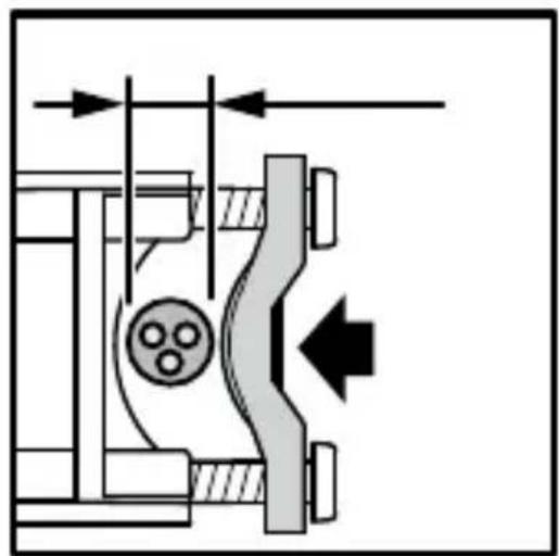
- Small cable diameter (right):
Attach the strain relief clamp as shown on the right.
5.20
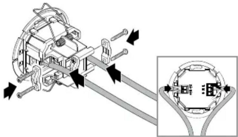
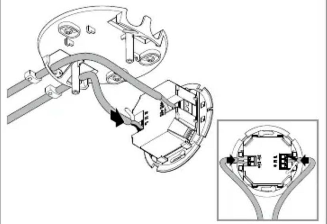
- Connect the power cable and DALI bus according to the circuit diagram.
- Attach the strain reliefs. "4. Electrical connection"
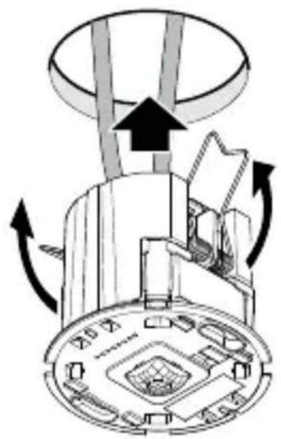
5.21
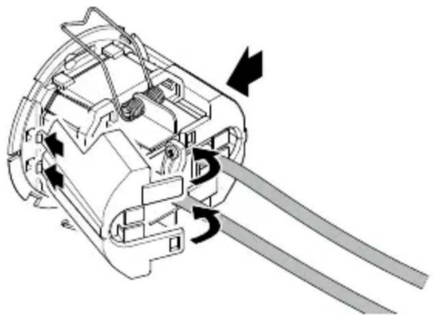
- Click in the side parts.
- If necessary, remove the wings of the side parts for the cable entry.
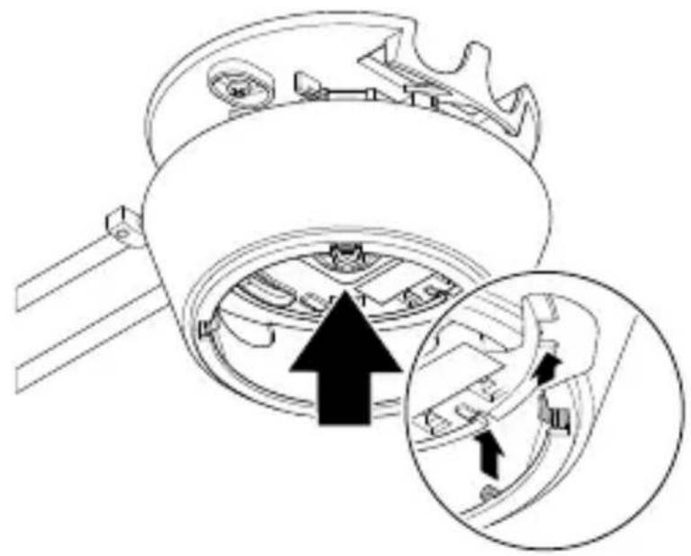
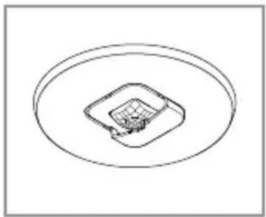
5.22

- Press the springs together upwards and insert the sensor module into the subceiling.
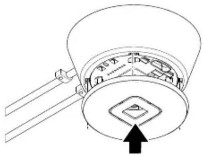
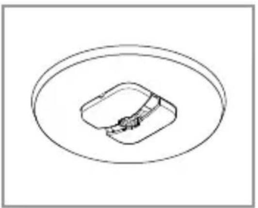
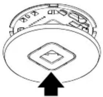
5.23

- Fit the cover.
5.24

- Switch ON power supply.
- Set the functions.
"6. Function"
6. Function
Factory settings
(before initial operation via Steinel Connect app)
- Fully automatic/semi-automatic: Fully automatic
- Main light time setting: 5 min
- Basic light: Off
- Reference brightness value: Internal
- Constant light control: Activated
- Constant light control threshold: 500lx
The factory settings are activated:
- When the presence detector is operated for the first time.
- When the presence detector is reset by the app.
Steinel Connect app
To configure the sensor with a smartphone or tablet, it is necessary to download the STEINEL Connect app from your AppStore. A Bluetooth-enabled smartphone or tablet is required.

Android iOS

Bluetooth networking (Bluetooth mesh)
The sensor conforms to the Bluetooth mesh standard. It can be networked with all products that comply with the Bluetooth mesh standard. The sensor is configured via the Steinel Connect app. The corresponding network keys are stored on the smartphone or tablet when the sensor and Steinel Connect app are connected for the first time. The network keys prevent unauthorised access to the sensor. The network key must be shared for access via another smartphone or tablet.
LED function
Initialisation: LED lights up for 10 seconds.
Identification: LED flashes every second.
Normal operation: LED off.
Test operation - motion: LED lights up.
Test operation - no motion: LED off.
Bluetooth grouping
It is possible to operate the device as a single sensor or to connect several sensors to form groups.
All sensors assigned to a group act according to the group parameters set in the Steinel Connect app. A sensor for the brightness measurement must be selected in each group. All group participants accept the brightness value transmitted by this sensor.
Neighbour function
The neighbouring groups are assigned to the active sensor group using the neighbour function. The group reacts to switch-on signals from the assigned neighbouring group and switches according to the settings.
Fully automatic
The lighting switches ON and OFF automatically depending on brightness and presence.
The lighting can be switched on manually at any time.
The automatic switching mechanism is temporarily interrupted.
Semi-automatic
The lighting only switches off automatically.
Switch-on takes place manually, light must be requested with a button and remains switched on for the set stay-ON time.
Twilight setting
The response threshold (twilight) can be infinitely varied from approx. 2 to 1,000 lux.

daylight mode (depending on ambient light level)

night-time operation (approx. 2 lux)
Daytime operation
Daytime operation is started by setting the twilight setting to the maximum. In daytime operation, the sensor switches the lighting on regardless of the ambient brightness if motion is detected.
Teach
With the help of the teach function, the twilight setting or the setpoint for constant light control can be set automatically based on the measured light conditions. When constant light control is deactivated, the twilight setting is set to the currently measured value for the ambient brightness. The light is automatically switched off during the process. If constant light control is active and the light is switched on, the setpoint for the control is set to the measured light value instead. The light should be dimmed manually in advance so that the target value is reached as precisely as possible. There is also the option of carrying out the teach procedure at a specified time.
Constant light control
If this function is activated, the lighting is regulated to a constant brightness setpoint. The brightness setpoint corresponds either to the response threshold set for the automatic brightness control or to the light value set via the teach function.
Main light
The settings in the main light define the behaviour for switching on the lighting when someone is present.
When constant light control is deactivated, the required light output is set via the dimming level.
When constant light control is activated, the lighting is controlled to the set brightness value.
The minimum light output that the controller must not fall below is then set via the dimming level. If 0% is selected, the controller can switch off the lighting completely if there is enough daylight. If the brightness falls below the target value again, the controller automatically switches the lighting back on.
The desired lighting duration of the main light can be set via the stay-ON time.
Any motion detected before this time has elapsed restarts the stay-ON time.
The fade time can be used to set the dimming curve when switching on and off.
Basic light
The settings in the basic light define the behaviour after the main light has been left after the stay-ON time has elapsed, if there is no one present.
It is switched back to the main light state if motion is detected during the basic light state.
The basic light can be deactivated or configured with the brightness-based or time-based functions.
With the basic light deactivated, the lighting is switched off immediately after the stay-ON time of the main light has elapsed. The basic light state is not executed.
Brightness-based function:
If the brightness-based function is activated, the basic light state is no longer left when there is no one present.
The desired light output for the basic light is set with the dimming level.
If the amount of daylight exceeds the response threshold, the basic light is switched off.
If the amount of daylight falls below the response threshold, the basic light is automatically switched on again.
Time-based function:
If the time-based function is activated, the basic light stay-ON time setting can be used to set how long the basic light should be active.
After the stay-ON time has elapsed, the basic light state is left and the lighting is switched off.
The desired light output for the basic light is set with the dimming level.
Fixed constant light control/dynamic constant light control
With fixed constant light control, the sensor does not save a manual override of constant light control by a button. With dynamic constant light control, on the other hand, the new brightness is set as the new control threshold.
In the case of manual override without constant light control activated in dynamic constant light control mode, the current light level is set as the new value for "Main light dimming".
Button input
Buttons can be integrated and configured via the STEINEL Connect app.
In order to be able to configure a button via input S, the product to which the button is connected must be assigned to a group.
In addition to input S, further buttons from the Bluetooth mesh network can be assigned to the sensor.
A function for a short and a long press of the button can be defined for each button. The following functions can be selected by means of a short button press:
- A button with the "On/Off" function can switch the lighting on and off manually.
- Manual switching off is not possible with the "On" function. The stay-ON time is restarted each time a button is pressed.
- With the "Off" function, the lighting can only be switched off manually.
- There are also the "On x min" and "Off x min" functions, with which the lighting can be switched on or off for a defined period of time.
The following functions can be selected by means of a long button press:
- A button with the "Dim up/Dim down" function can dim the lighting up and down manually.
- The "Dim up" function can only be used to dim the lighting up.
- The "Dim down" function can only be used to dim the lighting down.
A button is required to operate the sensor in semi-automatic mode.
In addition, calling up a preset scene can be assigned as a function to the button.
Presentation mode
If the light is switched off via a button, the sensor activates the presentation mode.
- The load remains switched off as long as motion is detected.
- As soon as no more motion is detected and the stay-ON time has elapsed, the sensor switches back to normal sensor operation.
Restriction of detection area
To prevent unintentional detection, the detection area can be limited with the shroud. With both shrouds attached, the detection range for motion is reduced to 3 × 6m and the detection range for presence to 2 × 4m .
6.1
- Mount the shroud on the sensor. Thread the hooks in at the front and then press down towards the back.
7. Cleaning and maintenance
The tool requires no maintenance.

Hazard from electrical power.
Contact between water and live parts can result in electrical shock, burns or death.
- Only clean tool in a dry state.
Risk of damage to property!
Using the wrong cleaning product can damage the light.
- Clean tool with a moist cloth without detergent.
8. Disposal
Electrical and electronic equipment, batteries, accessories and packaging must be recycled in an environmentally compatible manner.

Do not dispose of batteries or electrical and electronic equipment as domestic waste.
EU countries only:
Under the current European Directive on Waste Electrical and Electronic Equipment and its implementation in national law, batteries and electrical and electronic equipment no longer suitable for use must be collected separately and recycled in an environmentally compatible manner.
9. Conformity
STEINEL Vertrieb GmbH hereby declares that the radio equipment IR Micro Office DALI-2 Application Controller complies with Directive 2014/53/EU. The full text of the EU declaration of conformity is available at the following internet address: www.steinel.de
10. Manufacturer's warranty
As purchaser, you are entitled to your statutory rights against the vendor. If these rights exist in your country, they are neither curtailed nor restricted by our Warranty Declaration. We guarantee that your STEINEL Professional sensor product will remain in perfect condition and proper working order for a period of 5 years. We guarantee that this product is free from material-, manufacturing- and design flaws. In addition, we guarantee that all electronic components and cables function in the proper manner and that all materials used and their surfaces are without defects.
Making Claims
If you wish to make a claim, please send your product complete and carriage paid with the original receipt of purchase, which must show the date of purchase and product designation, either to your retailer or contact us at STEINEL (UK) Limited, 25 Manasty Road, Axis Park, Orton Southgate, Peterborough, PE2 6UP, for a returns number. For this reason, we recommend that you keep your receipt of purchase in a safe place until the warranty period expires. STEINEL shall assume no liability for the costs or risks involved in returning a product.
For information on making claims under the terms of the warranty, please go to www.steinel-professional.de/ garantie
If you have a warranty claim or would like to ask any question regarding your product, you are welcome to call us at any time on our Service Hotline 01733 366700.

11. Technical specifications
Dimensions (diameter × depth):
IR Micro Office DALI-2 APC AP: 106 × 45 mm
IR Micro Office DALI-2 APC UP: 85 × 37 ~mm
IR Micro Office DALI-2 APC DE: 85 × 69 ~mm
Input voltage: 220 - 240 V / 50/60 ~Hz
Power consumption in standby:
0.4 W without electronic ballast
DALI interface: 2-pin control line, single master
Application controller/broadcast.
Guaranteed supply current
40 mA according to IEC 62386-101,
equivalent to 20 DALI electronic ballasts.
Maximum supply current: 250 mA
Sensors: Passive infrared (IR)
Range: 4 × 4 m presence, radial,
6 × 6 m tangential
Detection angle:
Optimum mounting height: 2.8 ~m
Twilight setting:
2 - 1,000 lux, /daylight
Main light time setting:
5s-60min
Protection class:
IP 20
Temperature range:
0^ C to +40^ C
Frequency, Bluetooth:
2.4 - 2.48 GHz
Transmission power, Bluetooth:
Max. 10 dBm/10 mW
12. Troubleshooting
Unit without power.
-
Fuse not switched ON or faulty.
-
Switch ON fuse.
-
Change faulty fuse.
-
Break in wiring.
-
Check wiring with voltage tester.
- Short circuit in mains power supply lead.
-
Check connections.
-
Any mains switch OFF
-
Switch ON mains switch.
Unit does not switch ON.
-
Wrong twilight setting selected.
-
Reset twilight setting.
- Mains switch OFF.
-
Turn on mains switch.
-
Fuse not switched ON or faulty.
-
Switch ON fuse.
-
Change faulty fuse.
-
Rapid movements being suppressed to minimise malfunctioning, or detection zone too small or incorrectly defined.
-
Check and adjust detection zone.
Unit does not switch OFF.
-
Continued movement within the detection zone.
-
Check detection zone.
- If necessary, limit or change detection zone.
Unit switches ON when it should not.
- Floodlight not mounted for detecting movement reliably.
-
Securely mount floodlight.
-
Motion was present but was not detected by the observer (draught, heater nearby).
-
Check detection zone.
- If necessary, limit or change detection zone.
FR
Sommaire
IR Micro Office DALI-2 APC AP : 106 x 45 mm
IR Micro Office DALI-2 APC UP : 85 × 37 mm
IR Micro Office DALI-2 APC DE : 85 × 69 mm
Montagestappen IR Micro Office DALI-2 APC AP

5.3

IR Micro Office DALI-2 APC AP: 106× 45mm
IR Micro Office DALI-2 APC UP: 85 × 37 ~mm
IR Micro Office DALI-2 APC DE: 85 × 69 ~mm
Application Controller/Broadcast.
Vista general IR Micro Office DALI-2 APC AP
3.7
Vista general IR Micro Office DALI-2 APC UP
3.8

Vista general IR Micro Office DALI-2 APC DE
3.9
B = Sensor (Application Controller)
C =Botao
O aparecido también pode ser ligado a um interruptor de rede se ficar assegurar que o interruptor está sempre ligado.
Application Controller / Broadcast.
B = Sensor (Application Controller)
C =Knapp
Application Controller/Broadcast.
B = Sensor (Application Controller)
C =Trykknap
Installationstrin IR Micro Office DALI-2 APC AP
5.3

Installationstrin IR Micro Office DALI-2 APC UP
5.12


Application Controller / Broadcast.
Garanteret strømforsyning
B = Anturi (Application Controller)
C =Painike
IR Micro Office DALI-2 APC UP: Skjult variant
IR Micro Office DALI-2 APC DE: Variant takmontering
Leveringsomfang IR Micro Office DALI-2 APC AP
3.1

-1 takfeste
-1ramme
- 1 sensormodul
-1deksel
-2 sma skruer
-2dekkskall
-1 sikkerhetsdatablad
- 1 hurtigstart
Leveringsomfang IR Micro Office DALI-2 APC UP
3.2


- 1 sensormodul
-1deksel
-2dekkskall - 1 sikkerhetsdatablad
- 1 hurtigstart
Leveringsomfang IR Micro Office DALI-2 APC DE
3.3
1x
1x
2 ×
1x
1x

- 1 sensormodul
-1deksel
-2dekkskall - 1 sikkerhetsdatablad
- 1 hurtigstart
Monteringstrinn IR Micro Office DALI-2 APC AP

5.3


Sorg for at strormforsyningen er slatt av.
- Tegn borehull.

5.4

Monteringstrinn IR Micro Office DALI-2 APC UP
5.12


Bneta aouapmoooynoC IR Micro Office DALI-2 APC DE
5.16

Application Controller / Broadcast.
IR Micro Office DALI-2 APC AP: Siva üstü model
IR Micro Office DALI-2 APC UP: Siva alte model
IR Micro Office DALI-2 APC DE: Havana monteli model
IR Micro Office DALI-2 APC AP teslimat kapsami
3.1
IR Micro Office DALI-2 APC UP teslimat kapsami
3.2


Application Controller/Broadcast.
Garantált típáram
5 L A T GWARANCJI PRODUCENTA
11. Dane techniczne
Wymiary ( × gt.) ..
IR Micro Office DALI-2 APC AP: 106 × 45 mm
IR Micro Office DALI-2 APC UP: 85 × 37 ~mm
IR Micro Office DALI-2 APC DE: 85 × 69 ~mm
Consumul de energia in stand-by:
0,4 W fãrã balast electronic
Interfata DALI: Linie de control cu 2 pini, un singur master
Controller de aplicatie / Broadcast.
Current de alimentare garantat
40 mA conform IEC 62386-101,
echivalent cu 20 balasturi electronice DALI.
Current maxim de alimentare: 250 mA
Senzori: Infrarosu pasiv (IR)
Pregled uredaja IR Micro Office DALI-2 APC AP
3.7

IR Micro Office DALI-2 APC AP: Pindpaigaldatav variant
IR Micro Office DALI-2 APC UP: Varjatud variant
IR Micro Office DALI-2 APC DE: Lakke paigaldatav variant
Tarnekomplekt IR Micro Office DALI-2 APC AP
3.1

Toote mōṭmed IR Micro Office DALI-2 APC AP
3.4
Toote mōṭmed IR Micro Office DALI-2 APC UP
3.5

Toote mōṭmed IR Micro Office DALI-2 APC DE
3.6


B = Andur (Application Controller)
C = Nopp
Application Controller / Broadcast.
IR Micro Office DALI-2 APC AP": 106 x 45 mm
IR Micro Office DALI-2 APC UP": 85 × 37 ~mm
IR Micro Office DALI-2 APC DE": 85 × 69 mm
Jejimo jtampa: 220 - 240 V / 50 / 60 ~Hz
- Tiriet tikai sausu ieric.
Bojājumu risks!
lerici var sabojat, lietojot nepareizus tirisanas lidzeklus.
- Tiriiet ierici ar viegli mitru lupatiu bez tirisanas lidzekla.
8. Utilização
Pa3mepbl IR Micro Office DALI-2 APC AP
3.4
Pa3mepbl IR Micro Office DALI-2 APC UP
3.5

Pa3mepbl IR Micro Office DALI-2 APC DE
3.6

063op IR Micro Office DALI-2 APC AP
3.7

A IotoJIoHoe KpeJIeHne
B Kopnyc
C MecTo IopKJIoueHnA DALI-2
D CeHcOpHbI MOdUJIb
E MeTo IopKJIIOUeHnK 3JIeKTPoCetN
FПладон
063op IR Micro Office DALI-2 APC UP
3.8

A CeHcOpHbI MOdUJIb
B MeTo NOdkJIOUeHnK 3JIeKTPocETn
C MecTo IopKJIoueHnA DALI-2
0630p IR Micro Office DALI-2 APC DE
3.9
A Cko6a
B CeHcOpHbIM MoDyJIb
C MecTo IopKJIIOUeHnK 3JIeKTPoCeTn
D KompeHcaTOp HaTJXeHnA
4. Злес各项工作开展良好
Cxema nodkJIOUeHnA
4.1

ABC
N = HjleBOI npOBOD (aue BCero cnHn)
S = KHONKa
DA+ = NOДКЛЮЧЕНЕ K Шине DALI
DA- = NOДКЛЮЧЕНЕ K Шине DALI
PEKIM DHEBHOO OCBeUeHn (He3aBNCMO OT YRPKoCTn)

peKIM CymepeHOrO BKJIIOUeHnA CO 3HaueHnEM (ok.2Jk)
Днебун реким
Дnevнoi peжим 3anyckaetcnpn HacTroponke cymepek Ha makcimm.Вдnevнom peжime daTvnBkIIOuaeT OCBeueHne priOn obnapyxKeHHn DBNXeHnHa He3aBNCMO OT yapKocTN OkpykaHOUeN cpebl.
06yuHne
Функця обученя может сбыть Incnoьзова на дя aBTOMATUHECKO HabTPOIKN CymeK nII 3aDAHNO 3Ha- чENEДЯ рулрOBК NOCTOHHORO CBeTA Ha OCHOBe n3MpeHNBIX yCIOBNI OCBeIeHNOCTN. EcI IN peYIrpOBKa NoCTOHHORO CBeTa DeaKTINBIPOBaHa, HAcTPOIKA Cyme- peK yCTaHbJIbNAeTcR Ha TeKUeE n3MpeHHOe 3NaYeHne ЯрКоCTN OkpJkaHOne CpeIb. B 3TO BpeMЯ CBET aBTOMa- TNUeCKN BbIKJIouaETcR. EcI IN peYIrpOBKa NOCTOHHORO CBETA AKTINBIPOBaHa N CBET BKJIQUeH, BMeCTO 3TOFO 3aDAHHOE 3NaYeHne ДЯ рулрOBKn YcTaNAbJIbNAeTcR Ha n3MpeHHOe 3NaYeHne OCBeIeHNOCTN. CLeIyET 3apAHee dIMMInPOBaTb CBET BpyuHyI, YTObl 3aDAHHOe 3NaYeHne DoCTnraIocb KaK MoXHo TocHee. Kpome TorO, Функцю обченя можно IncnoьЗOBaTb B yCTaHOBJIen- HOe BpeMЯ.
Bpem3aTyxHnMOnKHO NcNoJb3OBaTb IJa HacTpOiKn KpNBoi DNMMnPoBaHnI Prn BkJIooHeHn I BbIKJIooHeHn.
Ba3OBoe ocBeueHne
Hactpoikn 6a3OBoro OCBeUeHnI ONpeJeJIOT NOBeHeHne DaTnka NocLe TORO, KaK nCTeueT BpEmr 3aTyXaHnIOCHOBHO OCBeUeHnI, B CJIyae OTCytCTBnI DnIXKeHnI. CnCTema nepeKJIouaetcra ObpaTHO B pexm OCHOBHOOCBeUeHnI, ecIn B peXmE 6a3OBoro OCBeUeHnI ObHa-pyXnBaETcra DBNXeHnI.
- YcTaHOBnTb KpbIuKn Ha DaTuNK. BcTaBnTb nepeHne KpUChN, a 3aTeM npJxKaTb 3aAnHIO YaCTb.
7.Чистка и ухов
I3dJIe He Tpe6yeT TexHnueCKoro 06cLyXKBaHna.
IR Micro Office DALI-2 APC AP: 106 × 45 MM
IR Micro Office DALI-2 APC UP: 85 × 37 MM
IR Micro Office DALI-2 APC DE: 85 × 69 ~mm
Bxodnoe napjxeHne: 220-240 \~B/50/60T
IopTe6JIeMaMoUHocTbBpeXmE OxuHaHnA:
0,4 Bτ 6e3 ΠPA
IHTeppeicDALI:
2-KoHTaKTHa JInn ynpaBHeHna,
ODHOBeDyUeeyCTPOIcTBO
CTepeHb 3aunTbI: IP20
- HenpaBnIbHO BbIbpaHa yCTaHOBKa cyMepeHOrO BKJIIOUeHnI.
3aHOBO OTpeYIpOBaTb yCTaHOBky cyMepeHOrO BKJIIOUeHnI.
-
CeteboBbIKIOuataTeIb BblKJI.
-
HaCTpOntb ceTeBOB BblKJIIOUaTeJIb.
-Прededхсантун He Вкlioочen Или Heисправен.
- Bключпь прдoxpaнтел.
3aMeHnTb HEnCnpaBhI npeOxpaHnteIb.
-ДлЯ MINHIMN3aци NOMex ьICTpbIe DBNXKeHЯ nRGOpnpyOTc IJIy UCTaHOBJIeHa CJIuXKOM MaJЯ 3OHa OБнapUxKeHЯ IJIY UCTaHOBJIeHa He KOppeKTHO.
- Ceh3op 3a MOHTaX Ha BbTppeWeH TaBaH BbB BbTppeW-HaTa 3OHa.
Функционален пинцин
- ИнфрачерВенят сEH3Ор пиХВаца TOПЛINHOTO n3ЛьчВане на DBИЖeши ce TeЯ (HaNP. Xopa, xINBOTHn).TOПЛINHOTO n3ЛьчВанe ceпpeo6pa3yBa eJIeKТрOHNo n aВТOMATИЧNO BКЛЮчВa LED-пpoжЕКТopa.
- Hαn-cnrgyphOTo 3acnUaHe ce nocTnra npN MOHTaK Ha ypeDa CtpaHnUHO cnprMo NOCOKaTa Ha DnIXKeHne.
- O6xbaTbT Ha 3acnuaHe e OgrpaHnueH, KOraTo DvNxKeHneTo e DnpeKTHo Cpeu cy CeH3Opa.
-Поради пpenятCTВЯ (нар.ДьрБета,С teHи ИлипpoЗорц) 3acuHaTeTo можедабдe огранчeHoИи HeBb3MOxHNo.
-ВнeзаПипомеиВ TemпераТураТа,поради КлиМатИчно ВлЯнe, He ce OTЛичавat OT ИЗТочни NaTOПЛиHa.
Ceptnuicnpahe:
To3n npoDyKT e cepTnΦnUpaH cBflacHo IEC 62386-103 KaTO Single-Master Application Controller. CLeIoBaTeJHo HeRoBOTO DALI 2 cepTnΦnUpaH nokpNbA camo npiLooKHeN, pRn KOnTo camo DALI EVG ("Control Gear") ca CBbP3aHn KbM DALI shHaTa.
IR Micro Office DALI-2 APC AP:Варпант за повьрхонс-TeH MOHTaЖ
IR Micro Office DALI-2 APC UP:Варпант за скрпТ MOHTаЖ
06xbat Ha doctabkaTa IR Micro Office DALI-2 APC AP
3.1
-1ДьржачзаТаВан
-1pamka
-1ceH3OpEnMoDyJ
-1kanak
-2MaJIKNBnHTa
-2 nokpmbn kanaKa
-1 daHn 3a 6e30napocct
-16bp3 cTapT
06xbat Ha doctabkata IR Micro Office DALI-2 APC UP
3.2


-1ceH3OpEnMoDyJ
-1kanak
-2 nokpmbn kanaKa
-1 daHHn 3a 6e30napocct
-16bp3 cTapT
06xbat Ha doctabkata IR Micro Office DALI-2 APC DE
3.3
2 ×
1x
1x
-1ceH3OpEnMoDyJ
-1kanak
-2 nokpmbn kanaKa
-1 daHHn 3a 6e30napocct
-16bp3 cTapT
Размери на пpoукта IR Micro Office DALI-2 APC AP
3.4

Pa3mepn Ha npoodykta IR Micro Office DALI-2 APC UP
3.5

Размери на пpoукта IR Micro Office DALI-2 APC DE
3.6

N = Hyla (obukHOBeHO cIH)
S = ByToH
DA+ = Bpb3ka KbM DALI BUS
DA- = Bpb3Ka KbM DALI BUS
A = Ламма DALI
B = CeH3op (Application Controller)
C = ByTOH
UpeIbT cIIO MOKe Ia 6bIe eJIeKTpIueCKn CBbp3aH CJIeI pIeKbCBaU, aKO Ce rapaHTnpa, Ye IpeKbCBaUbT Iue e BkJIIOUeH NOCTOJHHO.
3a okabelaheTo Ha cen30pa Baxn:
CbIacHo VDE 0100 520 Pa3dJe 6 3a okabeIbaHeTo
mexdy DALI EVG ("Control Gear") u DALI Application
Controller moxe da ce n3noJ3Ba MHOrOpOBoHa JInHna,
CbIbpxkaUa KaKTO npOBoHNuTe 3a MpeXkoBO Happe-
xKeHne, Taka n npOBoHNuTe 3a ynpaBJIeHne (HaNP.
NYM 5× 1,5)
MaKcImaJIHaTa IbIjxInHa Ha npoBoHnka MeJy DALIApplication Controller n DALI EVG ("Control Gear") He Tp8Ba Da NaBnShaBa 300 m (c 1,5 mm²). CJeI nHCTaJaCtЯ Ta N BkJIIOvBaHETo CBeTOnOJbT Ha CeH3Opa CBeTBA 3a 10 cekyni.
5. MoHTaЖ

Onachoct ot eJektpnueckn Tok!
CbaIeTe cTpaHnUHaTa yacT.
5.19
-
3aTЯGaS ce DnAmetbP ha npoBODnka 7,6 mm - 14,5 mm:
-
Голудnametbp Ha npobODnka (BJIBO).
Посравete сковата 3a pa3TOВане на habрженьeto, KaKTo e NOKa3aHO BЯBO.
MaJIbK dIaMeTbp Ha Ka6eJa (BdЯCHO):
Пocтавete скобараза разоварвано нанрженьeto, КakTo e ПOKa3aHO ВяCHO.
5.20

- CBbpxkTe 3axpaHbau n Ka6e n DALI shHaTa cnopei eJeKtpnueckaTa cxema.
- Пикpenete собITE 3a pa3TOBapBaHe Ha HanpexeHneTo.
→ „4.Електуеско CBbp3BaHe"
5.21
- ΦИКСИРаTe CTpaHnUHnTe YacTn.
- Ako e Heo6xOdmo, OTCTpaHete KpnlcaTa Ha cTpaHnHHe TaCTn Prn Ka6eHnBxOJ.
5.22
CTINCHETe npyKInHTe 3aeIHO HaOpe n NOCTaBete CEHNOPNMAOdyB OKaueHn TaBaH.
5.23
- NocTabete kanaka.
5.24

- EneKtpo3axpaHbAHeTo da ce BKJIIOU.
-Функцип Te Da ce HacTpOrt.
→6.Функця"
6.Функця
3aBODcN HacTpoiKN
(преши пускань веклноатця урет рпюжениeto
Steinel Connect)
- HanbJIHo/NoIyabTOMaTnUHO: HanbJIHo aBTOMaTnUHO
-ВрemeBa NaCTpoiKa, OCHOBHa CBeTInHa: 5 min - OCHOBHa CBETJIiHa: U3KJ
- Pepepeenzna, cToHocT ha npKocTTa: BbTppeHa
- YnpaBJIeHne Ha NOCTOJHHaTa CBETJIHa: AKTINBIPAHO
- Праз на упразавлие на посторнота CBetлina: 500 /x
Φa6pHnTe HaCTpoKn Ce aKTbBnpaT:
-При пьрвонаалностартуране на DeTeKTopa 3a ппсьства.
-Прин hyлране OT пиюжени.To.
3adoctbnppe3dpyrcmapTfoHnIITabJETMpexKOBnRT KIOU Tp8Ba da 6bde cnoJeH.
LEDФункця
Инциал��аця:LED cBeTba 3a 10 cekyнд.
IeHTnKau: CBeToIObT Mra Ha BcKa cekyHda.
HopmaJIeH peXIM Ha pa6Ota: LED n3KJI.
TecTob pexim Ha pa6oTa, DvIXeHne: LED cBeTn.
TecTob peKIM ha pa6Ota, 6e3 DBnXKeHne: LED n3Kn.
Груширанe,Bluetooth
Bb3MOxH0 e ycTpoiCTBOTo Da pa6OTn KaTO OTdJIeH cEH3Op nIIN HЯKOLKO cEH3Opa Da ce CBbPjXaT B rpyPi. BcNchKc cEH3Opn, pIpcBcOeHn Ha rpyNa, DeIcTBaT CnpeI rpyNoBITE napamEtpr, 3aIadEHN B npInIoJKeHneTo Steinel Connect. BbB BcraKa rpyNa TpIbBa Da sbJe n36paH cEH3Op 3a n3MepBaHe Ha JrkocCTTa. BcNchN yUacTHnCi N B rpyNaTa pIpeMaT CToHocCTTa Ha JrkocCTTa, npedabHa OT TO3N cEH3Op.
Функця СьсeДСТВО
Upe3ФyHKZIyTa CbSeIDCTBO CbSeHNITe rpyn Ce npICBOBArT Ha aKTHiBHaTa cEH3OpHa rpyna. rpynata pearnpa Ha cNrHaJI 3a BkJIIOuBaHe OT pncBcOeHaTa CbSeDNa rpyna I npeBkJIIOvBa cNopeJ NaCTPOJKeTe.
HaIbJIHo aBTOMaTnUHO
OcbetJIeHneTo ce BKJIIOUyBA n I3KJIIOUyBA aBTOMaTnHuHO B 3aBNCIMoCT OT rpkocTTa n npncbCTBneTO.
OcbetJIeHHeTo MoXe Da Ce BKnIOuN pBHyNo NO BCaKO BpeMe.
При TOВа abTOMaTINHOTO прБКЛIOчBaHe ВрЕмEHо CeпрЕкьСВа.
PonyaBTOMaTnUHcO
OcBETJIeHHeTo Ce I3KJIHOuBa CaMo aBTOMaTnUHO.
BkIIOUcBaHTo CtBa pBcHo, CBeTlnHaTa Tp8Ba Da 6bJe 3aJaDeHa C 6yToH n OCTaBa BkIIOUcHa 3a 3aJaDeHOTOBpeMe Ha NocJIeJeICTBVe.
Hactpoika Ha CBetIIOuyBCTBNTeJIHOCTTa
OcbeteHocTTa Ha 3aJeIcTBaHe (MpaK) MoKe da ce peYJInpa 6e3CTepeHNo OT Okolo 2 - 1 000 lykca.
-ДнHeBEN peXIM (He3aBnCmO OT OCBeTeHOCCTTa)
- = pejkm npn HacTbNbaa TbMHHa (OKOJ0 2 nyka)
Днебен рекин ha pa6ota
Дnevняп реким Ha paobTa ce CTapTupaЧpe3 3aДаВаHe Na HacTppoiKaTa 3a 3aTbMнЯBaHe Ha MaKcIyM. Прдnevп реким Ha paobTa ceH3OpbT BKJIIOvBa OCBeТлe-HneTo He3aBnCmO OT OKOLHaTЯрКoCT, aKO ce 3aCeYe DBNKeHne.
06yuHne
C nOMOuTa Ha ФyHKUraTa 3a obuchne HaCTpoiKaTa 3a 3aTbMnRAHe iIIN 3aIadEHaTa CToHocT 3a ynpabJeHne Ha NOCToRHHata CBETJIInHa MOrat Da 6bDaT HAcTPOeHN aBTOMaTHUHO Bb3 OCHOBa HA N3MepeHnte YcIOBnHa OCBTeHOCr. PpN De3akTbVbPaHo ynpabJeHne Ha NOCToRHHata CBETJIInHa 3aTbMnRABaHcToCe HAcTPOiBa Ha TEKUso N3MepeHata CToHocT 3a yapKOCTTa Ha OKOIHaTa cPeDa. 3a ZeTTa CBETJIInHa Ta Ce N3KJIIOUBy aBTOMaTHUHO IO BpeMe Ha npOceCa. Ako ynpabJeHneTo Ha NOCToRHHata CBETJIInHa e AKTUBHO I CBETJIInHaTa E BKJIIOUeHa, BMecTO TOBa 3aIadEHaTa CToHocT 3a ynpabJeHneTO Ce HAcTPOiBa Ha N3MepeHata CToHocT Ha CBETJIInHaTa. IpeDbapITeJIHo CBETJIInHaTa Tp8Ba Da ce HamaJI pBvHO, Taka Ye 3aIadEHaTa CToHocT Da CE DOCTURHe Bb3MOXHO Han-ToUHO. IMa i Bb3MOxHocT 3a npOBexJaHe Ha obyueHneTO B ONpeJelEHO YacOBO BpeMe.
YnpabJIeHne Ha NOCTOHHaTa CBETJINHa
Ako Ta3nФункця e aKTHBnpaHa, OCBeTJIeHneTO cepeRyInpa Do NOCTOJHHa 3aJaIeHa CToIHOCT Ha JRPKOCTTa.3aJaIeHaTa CToIHOCT Ha JRPKOCT CbOTBcETCTBa IJIi Ha npara Ha peakzra, 3aJaIeH 3a aBTOMaTnUHO ynpabJIeHne Ha JRPKOCTTa, IJIi Ha CToIHOCTTa Ha CBetJIiHaTa, 3aJaIeHa Upe3ФункцЯTa 3a O6yuHne.
OCHOBHa CBetJIiHa
HactpoiknteB OChOBHa CBeTInHa ONpeJeIaT NOVeJeHNeTO 3a BKJIouYBaHe Ha OCBETJIeHNeTo Pn IprNCbCTBVe.
При ДзakTNBИран KOHTpoJ Ha NOCTOЯHHaTa CBETJIHa, Heo6xOДIMaTa CBETJIINHa MOUHOC Tce HAcTpoJBa Upe3 HNBOTO Ha 3aTbMнЯBaHe.
При akтувиран Контюн на посторн ha CBETлиha, OCBetленьeto ce peулра до зааденata CTойноct Haярковта.
Чрз НВОТо на 3aТьМнЯВа He NaCTpoиВa МИнмал-нота CBETЛINHа MOцHOCT, Рд КОТо peглaTOрьТ He TpЯБВа Дa пада.При ИЗБор на 0% peглaTOрьТ може дa ИЗКЛЮчи habлJIHO OCBETЛeHneTO, aKO Има ДОCTaTbUHО Дnevва CBETЛиHa.Ак оркocTTa OTHOBO падHe ПOD 3aДa-ДeHATA CToIHOCT, peглaTOрьТ aBTOMaTnUHOb BKЛIOчВa OCBETЛeHneTO OTHOBO.
XeJHaTa npoIbJIxNtJIHOCT Ha CBeTeHe Ha OCHOBHaTa CBETInHa MOKe Da Ce HAcTpOn Upe3 BpeMeTo 3a IocJe-DeiCTBne.
BcraKo DvIXeHne, peRncTpnpaHO npEi n3TuHaHeTo Ha ToBa BpeMe, pecTapTnpa BpeMeTo 3a NocJeDeIcTBVe.
C Fade Time Moxe da ce NaCTpon KpNBaTa Ha 3aTbMnraBaHe npi BkIIOUbaHe n N3KJIIOUbaHe.
OCHOBHa CBetJINHa
HaCTpoIKeIte Ha OCHOBHaTa CBETJIHa ONpeIeJIr T NOBe-DeHHeTO CJIeI Ha NpUcKaHe Ha OCHOBHaTa CBETJIHa CJIeI N3TtUaHe Ha BPeMeTo 3a IocJIeIeIcTBVe B CJIyaui Ha OTCbCTBVe.