
IS 180-2 - Motion detector STEINEL - Free user manual and instructions
Find the device manual for free IS 180-2 STEINEL in PDF.


| Product type | Passive infrared (PIR) motion detector |
| Brand | Steinel |
| Model | IS 180-2 |
| Detection angle | 180° |
| Maximum range | 12 m (tangentially) |
| Switching power | 2200 W (incandescent), 1000 VA (CFL/LED) |
| Supply voltage | 230 V ~ 50 Hz |
| Protection rating | IP44 |
| Dimensions (H x W x D) | 120 x 90 x 130 mm |
| Weight | 0.2 kg |
| Housing material | UV-resistant plastic |
| Color | White |
| Mounting type | Wall or corner |
| Standby consumption | ~0.9 W |
| Adjustments | Twilight threshold (2-2000 lux), time delay (5 s – 15 min) |
| Twilight function | Yes, adjustable |
| Timer function | Yes, adjustable |
| Operating temperature | -20°C to +50°C |
| Certifications | CE, VDE |
| Manufacturer warranty | 3 years |
Frequently Asked Questions - IS 180-2 STEINEL
User questions about IS 180-2 STEINEL
0 question about this device. Answer the ones you know or ask your own.
Ask a new question about this device
Download the instructions for your Motion detector in PDF format for free! Find your manual IS 180-2 - STEINEL and take your electronic device back in hand. On this page are published all the documents necessary for the use of your device. IS 180-2 by STEINEL.
USER MANUAL IS 180-2 STEINEL

GB . . . 14 Follow written instructions!


Congratulations on purchasing this STEINEL Infrared Sensor and thank you for the confidence you have shown in us. You have chosen a high-quality product
that has been manufac- tured, tested and packed with the greatest care. Please familiarise yourself with these instructions before attempting to install the sensor since prolonged reliable and trouble-free op-
eration will only be ensured if it is installed properly.
We hope your new Infrared Sensor will give you lasting satisfaction.
1. System components
Security screw
2 Front cover
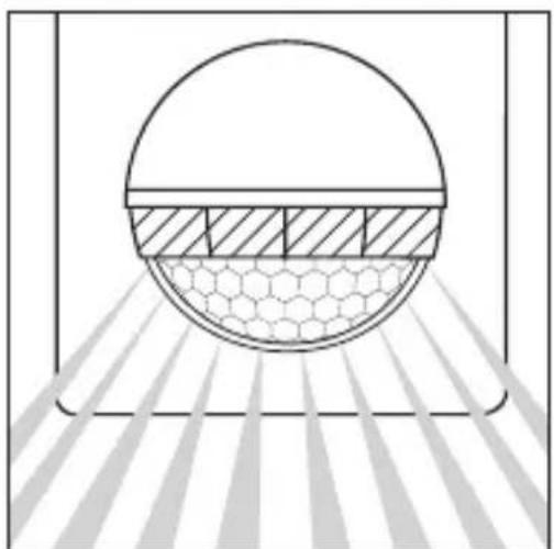
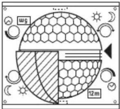
3 Lens (can be removed and turned for selecting the max. basic reach settings of 5 m or 12 m)
4 Light threshold setting control 2–2,000 lux
5 Time setting control 5 sec. -15 min.
6 Clip (housing can be flipped up for assembly and connection to mains power supply)
2. Technical specifications
Dimensions (H × W × D): 120 × 76 × 56 mm
Output: Incandescent / halogen lamp load: 1,000 W Fluorescent lamps, electronic ballast: 350 W (50 pcs. c < 132 μF)
Connection: 230–240 V, 50 Hz
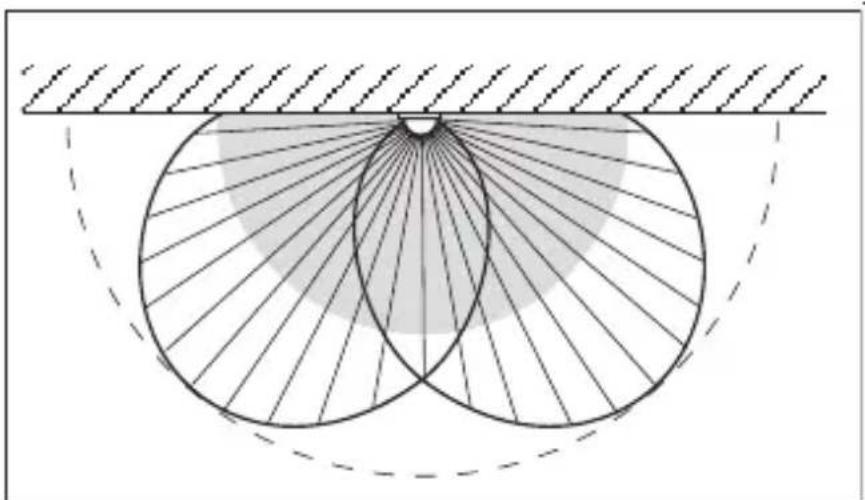
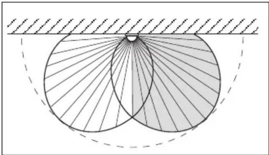
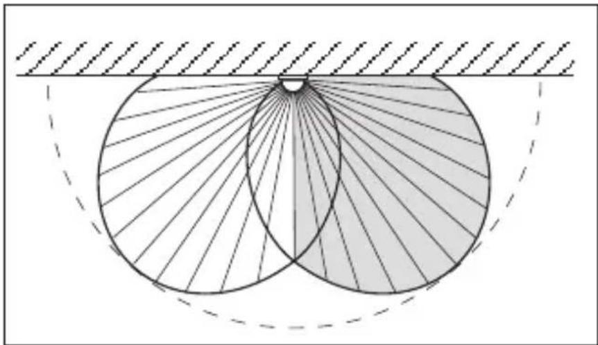
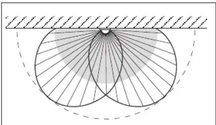
Detection angle 180° horizontal, 90° vertical
Sensor reach: basic setting 1: 5 m max. basic setting 2: 12 m max. (factory setting) + precision adjustment from 1–12 m by means of clip-on shrouds
Time setting: 5 sec. – 15 min. (factory setting: 5 sec.)
Light threshold: 2–2,000 lux (factory setting: 2,000 lux)
Enclosure: IP 54
Temperature range: -20 °C to +50 °C
3. Principle
GB
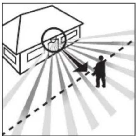
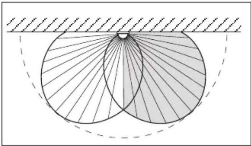
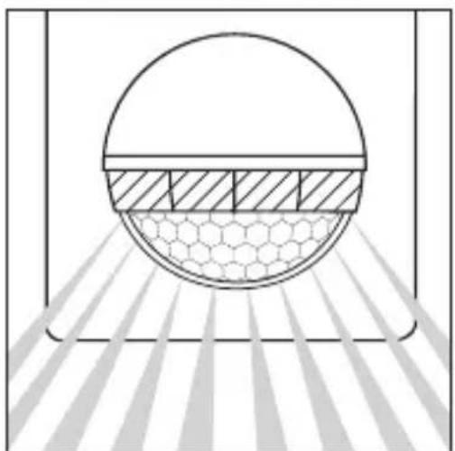
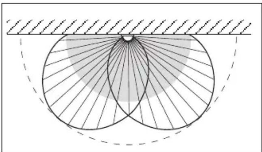
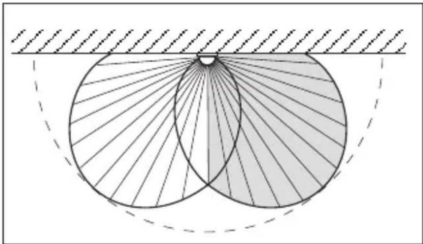
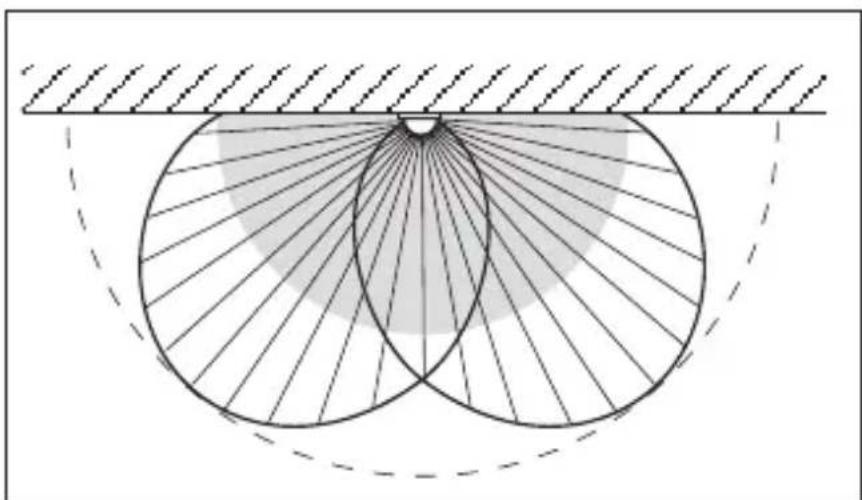
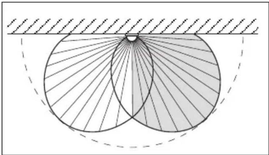
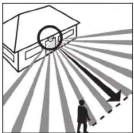
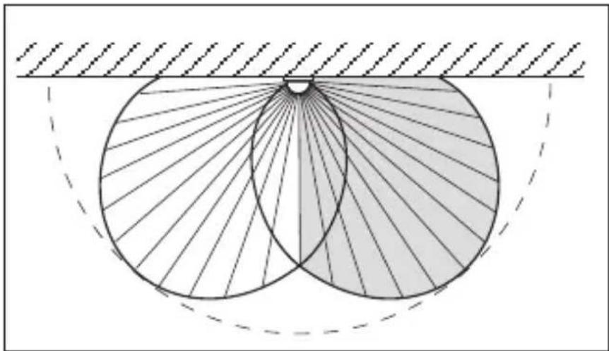
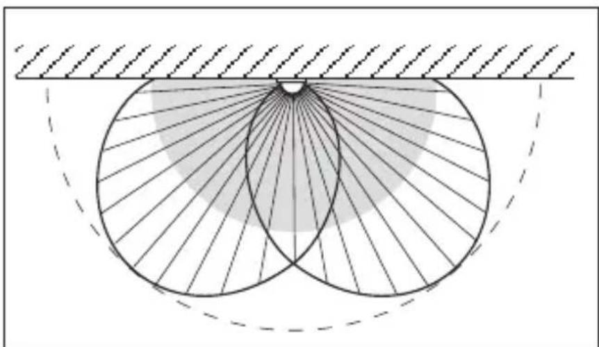
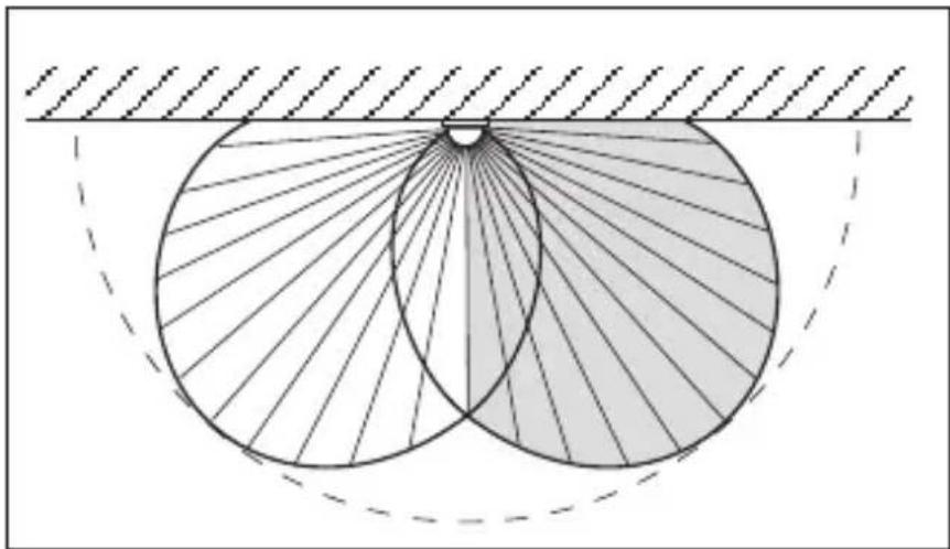
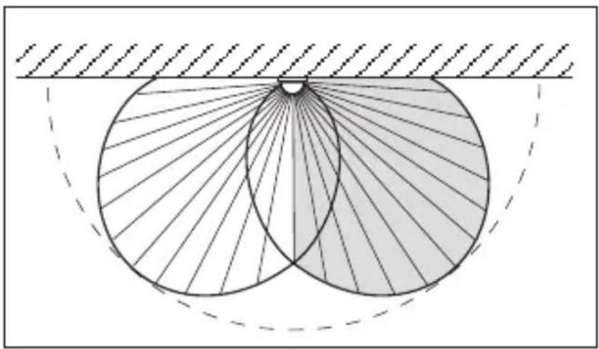
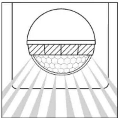
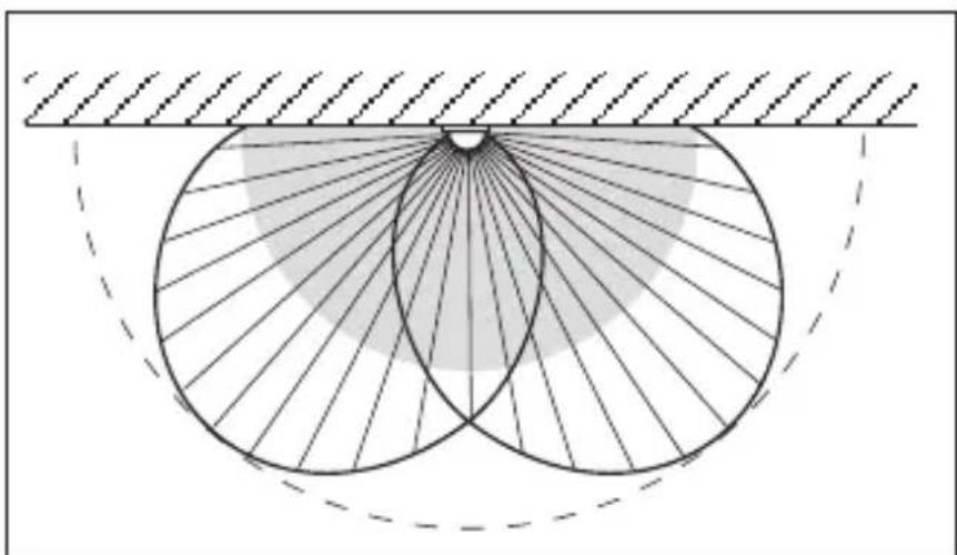
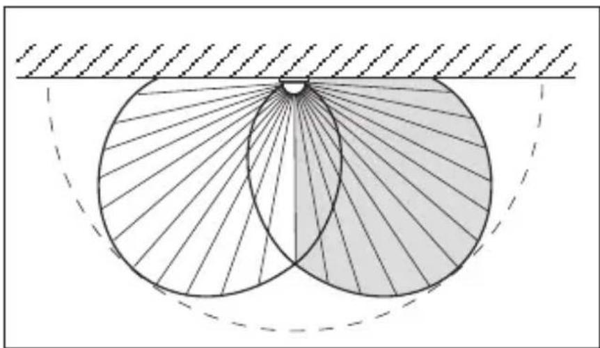
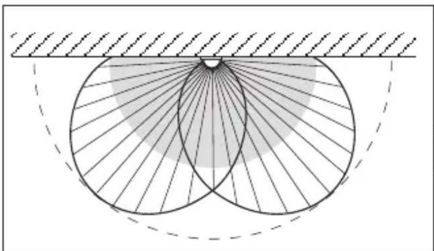
The IS 180-2 is equipped with two 120° pyro sensors which detect the invisible heat emitted by moving objects (people, animals etc.). The heat detected is electronically converted into a signal that switches on loads (e.g. a light) connected to it. Heat is not
detected through obstacles, such as walls or panes of glass. Heat radiation of this type will, therefore, not trigger the sensor. With a 90° angle of aperture, the two pyro sensors cover a detection angle of 180°. The lens can be removed and turned, thereby permitting
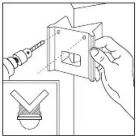
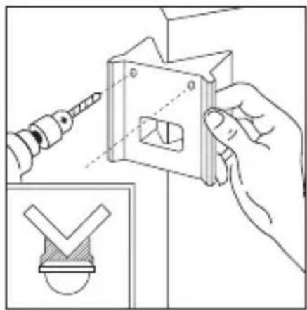
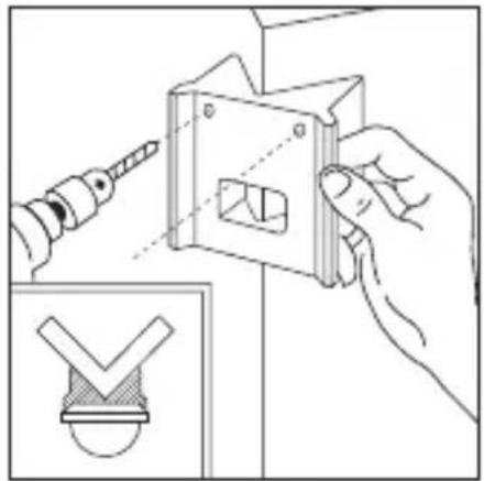
two max. basic reach set- tings of 5 m or 12 m. Using the wall mounts with the unit, the infrared sensor can easily be fitted to internal and external corners.


Reach max. 12 m Reach max. 5 m
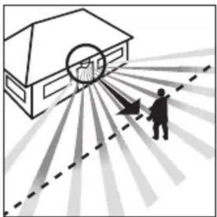
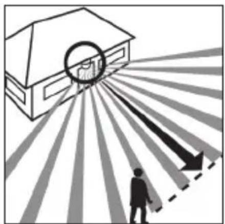
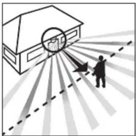
Direction of approach: towards the sensor

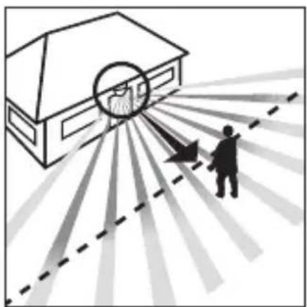
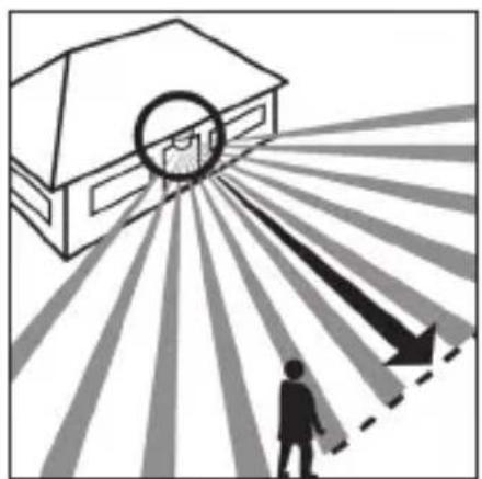
Direction of approach: across the detection zone
Important: The most reliable way of detecting motion is to install the unit so that the sensor is aimed across the direction in which a person would walk and by ensuring that no obstacles (such as trees, walls etc.) obstruct the line of sensor vision.

4. Safety warnings
■ Disconnect the power before attempting any work on the motion detector.
■ The electrical connection lead must be dead during installation. Therefore, switch off the power supply first and check that the circuit is disconnected using a voltage tester.
■ Installation of the sensor involves work on the mains power supply. This work must therefore be carried out professionally in accordance with the applicable wiring regulations and supply conditions.
■ Please note that the sensor must be protected by a 10 A circuit breaker. The mains supply lead must be no greater than 10 mm in diameter.
■ Only carry out time and light threshold settings with the lens fitted.
5. Installation / Wall mounting


Note: An inside corner wall bracket can also be used for wall mounting. This allows the cables to be conveniently routed from above behind the device and through the opening of the surface-mounted cable feed.
The site of installation should be at least 50 cm from a light because heat radiated from it may trigger the sensor unintentionally. To obtain the specified ranges of 5 / 12 m, the sensor should be installed at a height of approx. 2 m.
Installation procedure:
- Detach front cover 2
- Release clip 6 and flip up lower half of housing,
- Mark drill holes, 4. Drill the holes, insert wall plugs (6 mm dia.), 5. Break open cable entry for surface or concealed wiring.
- Feed through mains supply and service cable and connect to terminals. Use sealing plugs for surface wiring.
a) Connect mains supply lead
The mains supply leads is a 2 to 3-core cable:
L = phase conductor N = neutral conductor
PE = protective-earth conductor ( ⊖)
If you are in any doubt, you must identify the cables using a voltage tester; once you have done so, disconnect the power supply again. Connect the phase (L) and neutral conductor (N) to the clamp-type terminal. Connect the protective earth conductor to the earth terminal ()
A power ON / OFF switch may of course be installed in the power supply lead. Alternatively, you may use a normally closed contact pushbutton to activate the sensor manually for the duration of the time setting.
b) Connect service lead The service supply lead to the light is also a 2 to 3-core cable. Connect the light's current-carrying conductor to the terminal marked L'. The service lead neutral conductor must be connected to the terminal marked N together with the
mains lead neutral conductor. Connect the protective-earth conductor to the earth contact ( )
- Screw on housing and close again.
-
Fit lens (set reach to either 5 m or 12 m max), see 'Reach setting' section.
-
Select time 5 and light threshold setting 4 (see 'Functions' section).
- Locate front cover 2 and fit security screw 1 to protect cover from unauthorised removal.
Important: Reversing the connections may result in damage to the unit.
6. Installation using corner wall mount


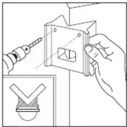
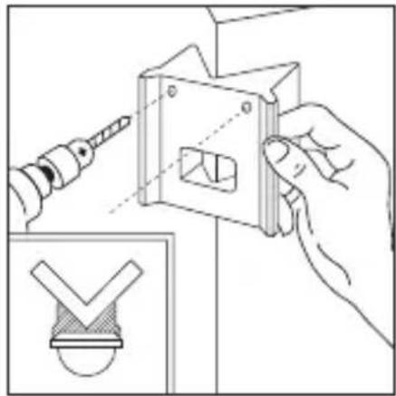
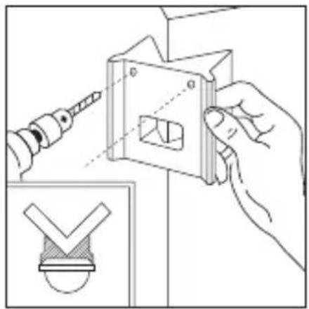
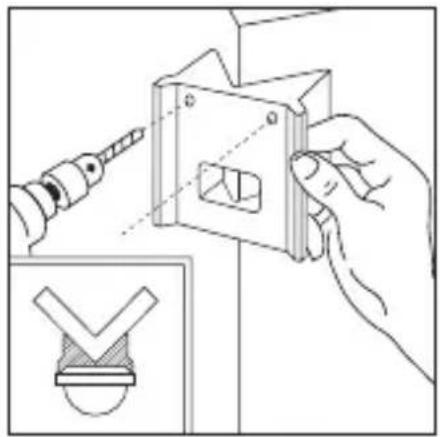
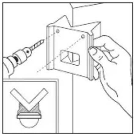
With the corner wall brackets, the IS 180-2 can be conveniently mounted on inside and outside corners. Use the corner wall bracket as a drilling template when drilling the holes. In this way you place the drill hole at the right angle and the corner wall bracket can be mounted without any problems.
The corner wall brackets are available separately: 4007841085131 black 4007841085148 white
7. Functions
Once you have connected the unit to the mains power supply, closed the housing and fitted the lens, you are
ready to put the system into operation. Two setting controls are concealed behind the front cover 21.
Important: Only carry out time and light threshold settings with the lens fitted.

Switch-off delay (time setting)
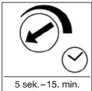
The chosen light ON time can be varied continuously from approx. 5 sec. to a maximum of 15 min. Turning the adjustment screw fully anti-clockwise selects the shortest time of approx. 5 sec., turning the adjust-
ment screw fully clockwise the longest time of approx. 15 min. The shortest time setting is recommended for setting the detection zone and performing the walk test.
Twilight setting (response threshold)
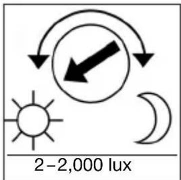
The chosen detector response threshold can be adjusted continuously from approx. 2 lux to 2,000 lux. Turning the adjustment screw fully anti-clockwise selects daylight operation at approx. 2,000 lux.
Turning the adjustment screw fully clockwise selects twilight operation at approx. 2 lux. The adjustment screw must be turned fully anti-clockwise for setting the detection zone and performing the walk test in daylight.
8. Basic reach settings

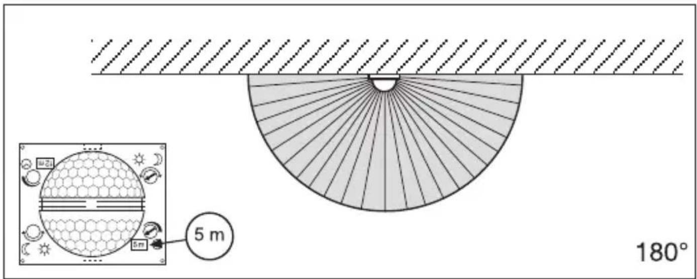
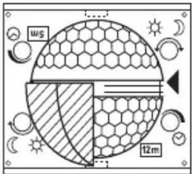
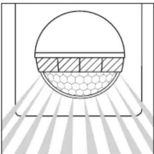
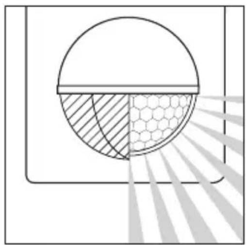
The lens of the IS 180-2 is divided into two detection zones. One half covers a max. reach of 5 m, the other half a max. reach of 12 m (when installed at a height of approx. 2 m). After fitting the lens (press lens firmly into the channel provided) you will see the max. reach setting (12 m or 5 m) at the bottom right.
Using a screwdriver, the lens can be unclipped from the groove at the side and re-positioned for the reach you require.
9. Examples

10. Precision adjustment using shrouds
GB

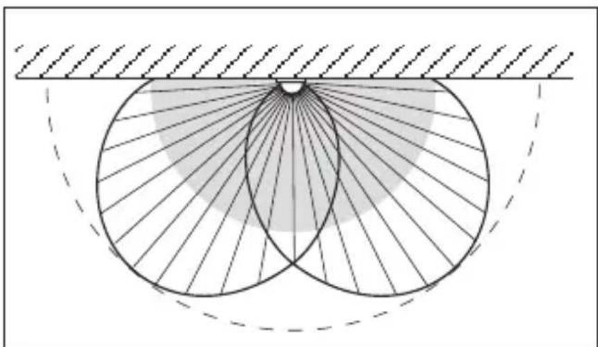
Shrouds may be used to define the detection zone exactly as you require in order, for example, to blank out or specifically target paths or neighbouring premises.
The shrouds can be divided or cut with a pair of scissors along the vertical and horizontal grooves. They can be clipped into the top channel around the centre of the lens. They are fixed in place by fitting the front cover.

(See below: Examples showing how to reduce the angle of detection and shorten the reach).
11. Examples


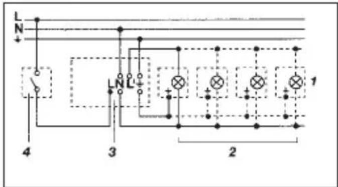
12. Wiring examples
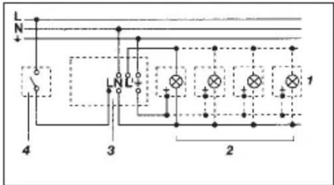

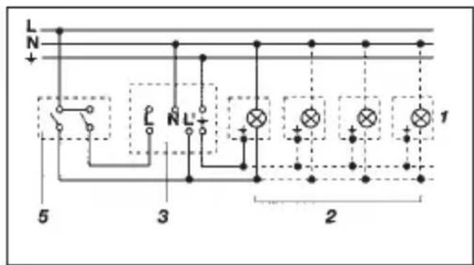
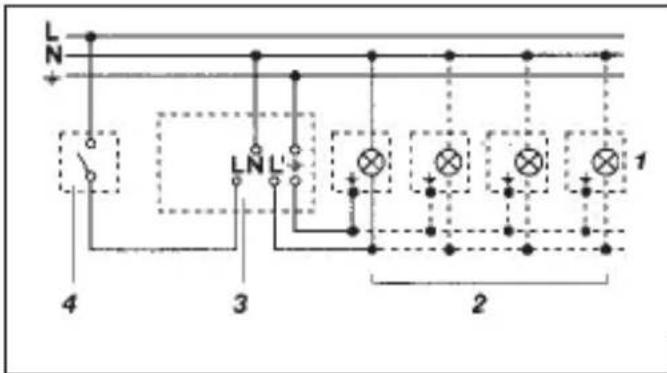
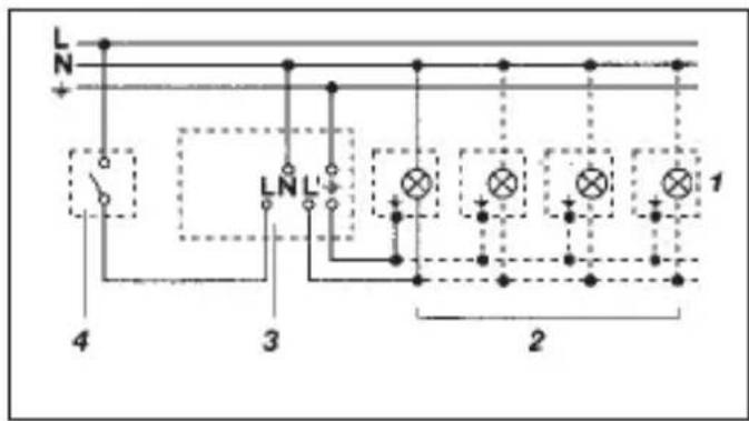
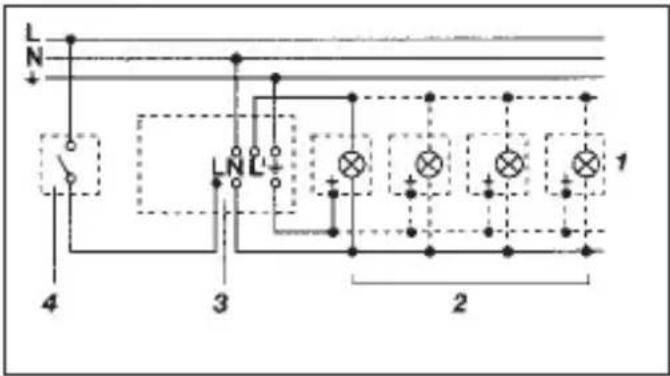
- Light without neutral conductor 2. Light with neutral conductor

- Connection using series switch for manual and automatic operation

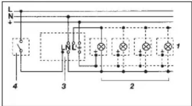
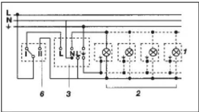
4. Connection to double-throw switch for permanent light ON and automatic operation
Setting I: automatic operation Setting II: manual operation for permanent light ON Important: the unit cannot be switched OFF, but operated only at settings I and II.
1) e.g. 1-4 × 100 W filament bulbs
2) Service load, light of 1,000 W max. (see Technical specifications)
3) IS 180-2 connection terminals
4) Indoor switch
5) Indoor series switch, manual, automatic
6) Indoor double-throw switch, automatic, permanent light ON
13. Operation / Maintenance
The Infrared Sensor is suitable for switching light on and off automatically. The unit is not suitable for special burglary alarm systems since it lacks the tampering protection prescribed for this purpose.
Weather conditions may affect the way the motion detector works. Strong gusts of wind, snow, rain or hail may cause the light to come on when it is not wanted because the sensor is unable to distinguish
sudden changes of temperature from sources of heat. The detector lens may be cleaned with a damp cloth if it gets dirty (do not use cleaning agents).
14. Troubleshooting
GB
Malfunction Cause Remedy
| IS 180-2 without power | ■ Fuse faulty; not switched ON■ Short circuit■ Mains switch OFF | ■ Renew fuse, switch on mains power switch, check wiring with voltage tester■ Check connections■ Switch on |
| IS 180-2 will not switch ON | ■ Twilight control set to nighttime mode during daytime operation■ Bulb faulty■ Mains power switch OFF■ Fuse faulty■ Detection zone not properly targeted | ■ Adjust setting■ Change light bulb■ Switch on■ Renew fuse, check connection if necessary■ Re-adjust |
| IS 180-2 will not switch OFF | ■ Continuous movement in the detection zone■ Light is in detection zone and keeps switching on as a result of temperature change■ Set to continuous operation by indoor series switch.■ Position Wi-Fi device very close to the sensor | ■ Check detection zone and re-adjust if necessary or fit shrouds■ Re-adjust zone or apply shroud■ Set series switch to automatic mode■ Increase distance between Wi-Fi device and sensor |
| IS 180-2 keeps switching ON / OFF | ■ Light is in detection zone■ Animals moving in detection zone■ Heat source (e.g. extractor hood outlet) in detection zone | ■ Adjust detection zone or fit shrouds, increase distance■ Adjust detection zone or fit shrouds■ Adjust detection zone or fit shrouds |
| IS 180-2 switches on when it should not | ■ Wind is moving trees and bushes in the detection zone■ Cars in the street are being detected■ Sudden temperature changes due to weather (wind, rain, snow) or air expelled from fans or open windows | ■ Blank off sections using shrouds■ Blank off sections using shrouds■ Adjust detection zone or change site of installation |
15. Disposal
Electrical and electronic equipment, accessories and packaging must be recycled in an environmentally compatible manner.

Do not dispose of electrical and electronic equipment as domestic waste.
EU countries only:
Under the current European Directive on Waste Electrical and Electronic Equipment and its implementation in national law, electrical and electronic equipment no longer suitable for use must be collected separately and recycled in an environmentally compatible manner.
16. Manufacturer's Warranty
Manufacturer's warranty of STEINEL GmbH, Dieselstrasse 80-84, DE-33442 Herzebrock-Clarholz, Germany
All STEINEL products meet the highest quality standards. For this reason, we, the manufacturer, are pleased to provide you, the consumer, with a warranty under the following terms and conditions: The warranty covers the absence of deficiencies which are proven to be the result of a material defect or fault in manufacturing and which are reported to us immediately after detection and within the warranty period. The warranty shall apply to all STEINEL products sold and used in Germany - excluding STEINEL Professional products.
You can opt for warranty cover in the form of repair or replacement which will be provided free of charge (if applicable, in the form of a successor model of the same or higher quality) or in the form of a credit note. The warranty period for the STEINEL product you have purchased is 3 years (5 years for products from the XLED home range) in each case from the date on which the product was purchased.
We shall bear the shipping costs but not the transport risks involved in return shipment.
Statutory rights accruing from defects, gratuitousness
The warranty cover described here shall be applicable in addition to the statutory rights of warranty – including special consumer protection provisions – and shall not restrict or replace them. Exercising your statutory rights in the event of defects is gratuitous.
Exemptions from the warranty
All replaceable lamps are expressly excluded from this warranty. In addition to this, the warranty shall not cover:
- any wear resulting from use or any other natural wear of product parts or any deficiencies in the STEINEL product that are attributable to wear caused by use or other natural wear, - any improper or non-intended use of the product or any failure to observe the
operating instructions,
- any unauthorised additions, alterations or other modifications to the product or any deficiencies attributable to the use of accessory,
- supplementary or replacement parts which are not genuine STEINEL parts,
- any maintenance or care of products that is not carried out in accordance with the operating instructions,
- any attachment or installation that is not in accordance with STEINEL's installation instructions,
- any damage or loss occurring in transit.
16. Manufacturer's Warranty
GB
Application of German law The warranty shall be governed by German law excluding the United Nations Convention concerning the International Sale of Goods (CISG).
Making claims If you wish to make a warranty claim, please send your product complete and carriage paid with the original receipt of purchase, which must show the date of purchase and product designation, either to your retailer or directly to us at STEINEL (UK) Ltd. – 25 Manasty Road, Axis Park, Orton Southgate, GB-Peterborough Cambs PE2 6UP United Kingdom. For this reason, we recommend that you keep your receipt of purchase in a safe place until the warranty period expires.
FR
Cher client,
Charge LED / ballast
électronique: 350 W (50 pcs. / pcs. c < 132 μF)



Schemerinstelling (drempelwaarde)





Alcance máx. 12 m Alcance máx. 5 m
Regulación crepuscular (punto de luz ambiental)



- Lámpara sin conductor neutro 2. Lámpara con conductor neutro
Alcance máx. 12 m Alcance máx. 5 m




12. Kopplingsexempel



- Tilslutning via seriekontakt til manuel og automatisk drift

4. Tilslutning via skiftekontakt til konstant belysning og automatisk drift




grunninnstilling 2: maks. 12 m (forinnstilling)
Rekkevidde maks. 12 m Rekkevidde maks. 5 m


Skumringsinnstilling (Lysnivå)





- Nötr iletken bulunmayan lamba 2. Nötr iletken bulunan lamba


Dosah max. 12 m Dosah max. 5 m





Dosah max. 12 m Dosah max. 5 m


Nastavenie stmievania (prah citlivosti)


Directia de deplasare: frontal
Directia de deplasare: lateral
N = conductor de nul


12. Exemple de conectare
Doseg maks. 12 m Doseg maks. 5 m

Smer hoje: frontalna Smer hoje: stranska
Pomembno: Zaznavanje premikanja bo najbolj za- nesljivo, će montirate aparat s strani na smer hoje, zaznavanja senzorja pa tudi ne smejo ovirati nobene ovire (kot so npr. drevesa, zidovi itd.).

4. Varnostna navodila
■ Pred vsemi deli na javljalniku gibanja je treba prekiniti dovajanje napetosti!
Ob montaži mora biti električni vodnik, ki ga boste priključili na aparat, brez napetosti. Žato najprej izklopite tok ter z indikatorjem napetosti preverite, da naprava ni pod napetostjo.


SI
12. Primeri priklopa


Domet maks. 12 m Domet maks. 5 m
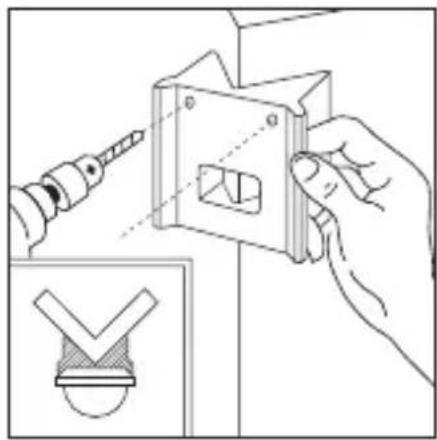
Uz kutne zidne drža- če, IS 180-2 može se jednostavno montirati na unutarnje i vanjske kutove. Upotrijebite kutni zidni držač kao predložak za bušenje tijekom bušenja rupa. Na taj način postav- ljate izbušenu rupu pod pravim kutom i kutni zidni držač može se montirati bez problema. Kutni zidni držači dostupni su zasebno: 4007841085131 crni 4007841085148 bijeli
7. Funkcije
Nakon što je izveden priključak na mrežu, kućište zatvoreno i stavljena leća, možete aktivirati uređaj.
Iza dizajniranog prednjeg poklopca 2 postoje dvije mogućnosti podešavanja.
Važno: Vrijeme i svjetlosni prag podešavajte samo kad je leća montirana.
Kašnjenje isključivanja (Podešavanje vremena)
Željeno trajanje svjetla može se kontinuirano podesiti od približno 5 sek. do maks. 15 min. Korekcijski vijak na lijevom graničniku znači najkraće vrijeme približno 5 sek., a korekcijski vijak na
desnom graničniku znači najduže vrijeme od približno 15 min. Kod podešavanja područja detekcije kao i za test funkcioniranja preporučuje se podesiti najkraće vrijeme.








L = a 3 a
N = Hy на
PE = 3 azemjabaupnpovodhink ( ②)




走动方向:正面 走动方向:侧面

亮度设置
(响应阀值)
为了隔离其他范围(例如,
走道或邻近区域),或进行专
门监控,须通过安装遮光板
准确设置感应范围。
遮光板可以沿着预开槽的分
割线垂直和水平分开,或通
过剪床切开。然后,其可悬
挂在镜头中间最上部凹槽上。
通过安装饰板可最终将其固
定。(参见下文:如何减小感
应角度及缩短有效距离的示
例。)

11. 示例


12. 连接示例
- 灯,无零线

- 灯,有零线

- 通过用于手动和自动运行的串联开关连接


Contact
www.steinel.de/contact


- SYSTEM COMPONENTS
- TECHNICAL SPECIFICATIONS
- PRINCIPLE
- SAFETY WARNINGS
- INSTALLATION / WALL MOUNTING
- INSTALLATION PROCEDURE
- CONNECT MAINS SUPPLY LEAD
- INSTALLATION USING CORNER WALL MOUNT
- FUNCTIONS
- SWITCH-OFF DELAY (TIME SETTING)
- TWILIGHT SETTING (RESPONSE THRESHOLD)
- BASIC REACH SETTINGS
- EXAMPLES
- PRECISION ADJUSTMENT USING SHROUDS
- WIRING EXAMPLES
- CONNECTION TO DOUBLE-THROW SWITCH FOR PERMANENT LIGHT ON AND AUTOMATIC OPERATION
- OPERATION / MAINTENANCE
- TROUBLESHOOTING
- DISPOSAL
- EU COUNTRIES ONLY
- MANUFACTURER'S WARRANTY
- STATUTORY RIGHTS ACCRUING FROM DEFECTS, GRATUITOUSNESS
- EXEMPTIONS FROM THE WARRANTY
- FR
- CHER CLIENT
- SCHEMERINSTELLING (DREMPELWAARDE)
- REGULACIÓN CREPUSCULAR (PUNTO DE LUZ AMBIENTAL)
- KOPPLINGSEXEMPEL
- TILSLUTNING VIA SKIFTEKONTAKT TIL KONSTANT BELYSNING OG AUTOMATISK DRIFT
- SKUMRINGSINNSTILLING (LYSNIVÅ)
- NASTAVENIE STMIEVANIA (PRAH CITLIVOSTI)
- EXEMPLE DE CONECTARE
- VARNOSTNA NAVODILA
- PRIMERI PRIKLOPA
- FUNKCIJE
- KAŠNJENJE ISKLJUČIVANJA (PODEŠAVANJE VREMENA)
- 示例
- 连接示例
- CONTACT
Brand : STEINEL
Model : IS 180-2
Category : Motion detector