
ST 008789 - Motion detector STEINEL - Free user manual and instructions
Find the device manual for free ST 008789 STEINEL in PDF.


| Product type | Passive infrared (PIR) motion detector |
| Brand | Steinel |
| Model | ST 008789 |
| Dimensions (L x H x D) | 120 x 80 x 70 mm |
| Weight | 150 g |
| Power supply | 230 V AC, 50 Hz |
| Rated power | 2000 W max (incandescent lamp), 600 W max (LED) |
| Detection angle | 180° |
| Detection range | Up to 12 m |
| Brightness threshold adjustment | Yes, from 2 to 2000 lux |
| Time delay | Adjustable from 5 seconds to 15 minutes |
| Operating modes | Auto, Manual (test), Off |
| Protection rating | IP44 (splash-proof) |
| Operating temperature | -20 °C to +50 °C |
| Main functions | Motion detection, sensitivity adjustment, time delay, brightness threshold |
| Care and cleaning | Clean with a soft, dry cloth. Do not use abrasive products. |
| Safety | Installation and maintenance reserved for a qualified electrician. |
| Spare parts and repairability | No spare parts available. Contact Steinel customer service. |
| General information | CE certification. 2-year warranty. |
Frequently Asked Questions - ST 008789 STEINEL
User questions about ST 008789 STEINEL
0 question about this device. Answer the ones you know or ask your own.
Ask a new question about this device
Download the instructions for your Motion detector in PDF format for free! Find your manual ST 008789 - STEINEL and take your electronic device back in hand. On this page are published all the documents necessary for the use of your device. ST 008789 by STEINEL.
USER MANUAL ST 008789 STEINEL
Intelligent Lighting for Professionals.

IR Quattro DALI IR Quattro HD DALI
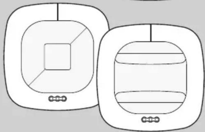
HF 360 DALI DUAL HF DALI
DALI

i
13

IR Quattro DALI
IR Quattro HD DALI

HF 360 DALI / DUAL HF DALI

⑨


Poti⑧

Technische Daten
GB Operating Instructions
Dear Customer,
Congratulations on purchasing your new STEINEL sensor and thank you for the confidence you have shown in us. You have chosen a high-quality product that has been manufactured, tested and packed with the greatest care.
Please familiarise yourself with these instructions before attempting to install the product because prolonged, reliable and trouble-free operation will only be ensured if it is fitted and used properly.
We hope your new STEINEL sensor will bring you lasting pleasure.
Safety Precautions
■ Disconnect the power supply before attempting any work on the sensor!
During installation, the electric power cable to be connected must be dead. Therefore, switch 'OFF' the power first and use a voltage tester to make sure the wiring is off circuit.
■ Installing the sensor involves work on the mains power supply. This work must therefore be carried out professionally in accordance with the applicable national wiring regulations and electrical operating conditions (VDE 0100).
Assembly/Installation ⑬ (see fig. on page 2)
The sensor is only suitable for recessed ceiling installation indoors. A clamping-type ceiling adapter or surface-mounting adapter is not included.
Sensor and load module come ready assembled and must be plugged together after fitting the load module and setting the potentiometers/dip switches. The sensor module must now be locked in place with the catch mechanism ⑫, using a screwdriver if necessary.
Accessories: Kaiser junction box for stud walls EAN No.: 4007841 000370 Clamping-type ceiling adapter EAN No. 4007841 002855 Surface-mounting adapter, EAN No.: 4007841 000363 Guard cage, EAN No.: 4007841 003036 Service remote control RC 3, EAN No.: 4007841 000387 User remote control RC 5, EAN No.: 4007841 592806
System Components
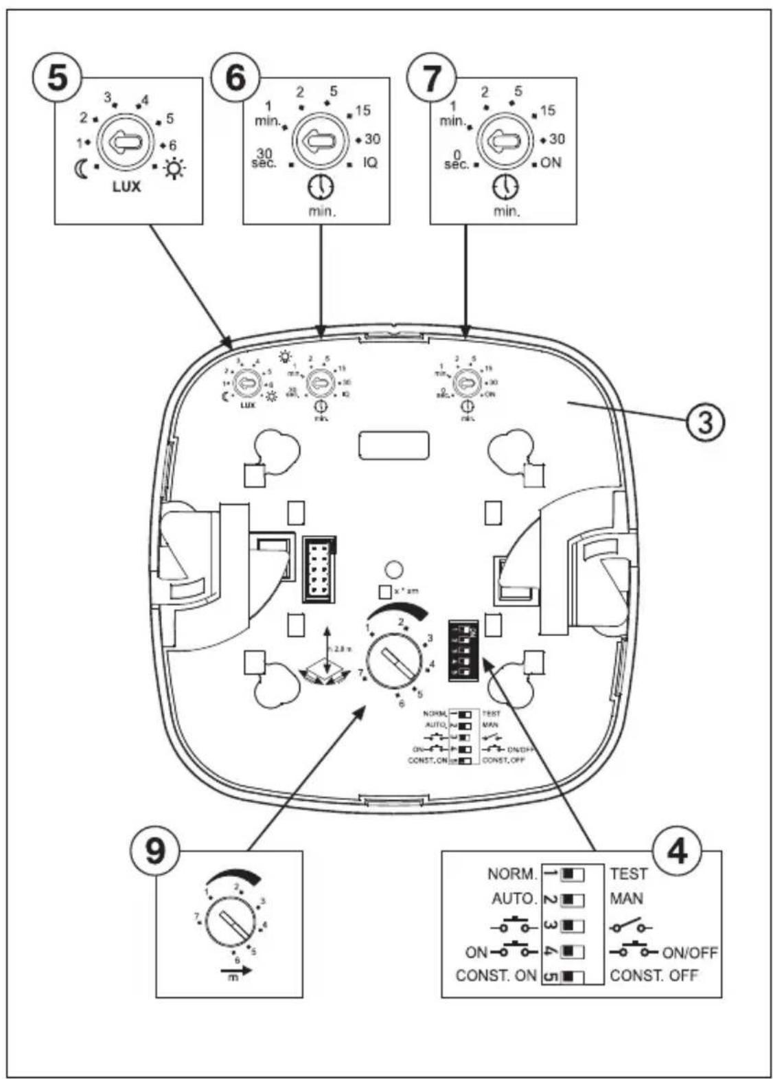
① Load module
② Sensor module
③ Sensor base
④ Dip switches
(1) Normal mode/Test mode
(2) Semi-/fully automatic mode
(3) Button/switch
(4) 'ON' / 'ON-OFF' button
(5) Constant-lighting control 'ON'/'OFF'
⑤ Twilight setting
⑥ Time setting
Switching output 1
⑦ Basic brightness
⑧ Reach setting (IR)
⑨ Reach setting (HF)
⑩.1 Kaiser stud-wall junction box, optional
⑩ Clamping-type ceiling adapter, optional,
⑪ Surface-mounting adapter IP 54, optional
⑫ Locking mechanism
⑬ Assembly/Installation
⑭ Parallel-connected configurations
⑮ Shrouds for minimising the detection zone (HF 360 DALI)
How It Works / Basic Function
The infrared presence detectors from the Control PRO range control lighting, e.g. in offices, WC's, public buildings or at home, in relation to ambient light level and the presence of persons.
Modern, high-frequency technology guarantees that movement is detected absolutely anywhere irrespective of radiated temperature.
Sensing movement in two directions, the DUAL HF DALI sensor is ideal for corridors in hotels, schools and office buildings. The PIR sensor (passive infrared sensor) IR Quattro DALI with highly advanced lens provides a square detection zone, as the typical shape of a room, in which the smallest of movements are sensed.
The presence detector's switching outputs and reach are set at the potentiometers and dip switches or by means of the optional remote control.
Presence Control has a low intrinsic power consumption.
Presence Control PRO
IR Quattro DALI IR Quattro HD DALI
HF 360 DALI DUAL HF DALI
2 DALI switching outputs operating in relation to brightness setting and presence of persons.
Settings:
- Brightness setting
- Stay-'ON' time, IQ mode
- Orientation light
- Constant-lighting control
- Scene control
Detection Zone
IR Quattro DALI / IR Quattro HD DALI
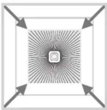
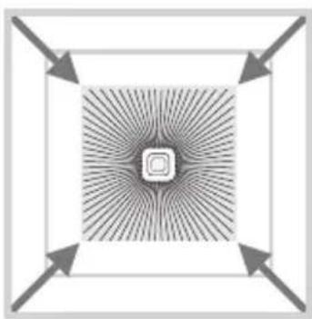
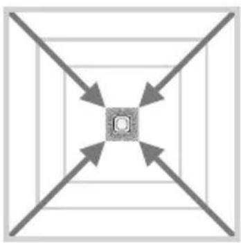
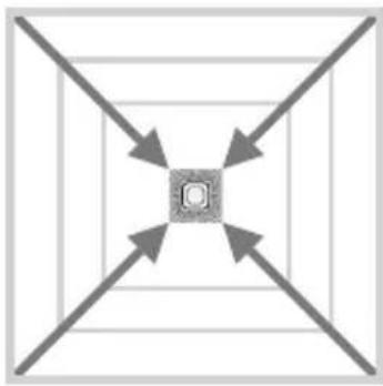
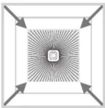
Reliable presence detection largely depends on the number, condition and arrangement of the lens segments. The IR Quattro DALI with its square detection zone of 49 m2 divided up into 13 levels and 1760 switching zones senses the smallest of movements. With a square detection zone covering an area of 64 m2 , the IR Quattro HD DALI has

4800 switching zones that provide even greater precision. These reaches can be adjusted to suit specific requirements at the setting potentiometer. The square detection zone provides the basis for creating optimum configurations quickly and easily.
Reach Setting (IR Quattro DALI / IR Quattro HD DALI)


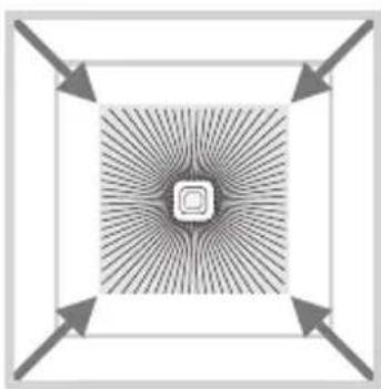
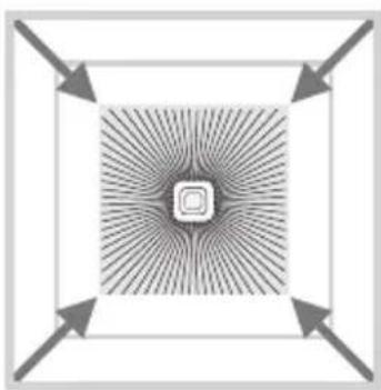
Potentiometer ⑧
Adjusts reach to specific requirements.
See table on pages 6-7 showing Technical Specifications for selecting settings to suit specific requirements.
Reach Setting (HF 360 DALI / DUAL HF DALI)
HF 360 DALI - mounting height 2.8 m DUAL HF DALI - mounting height 2.8 m

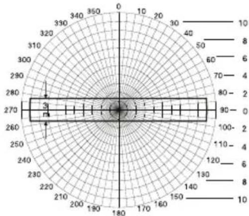
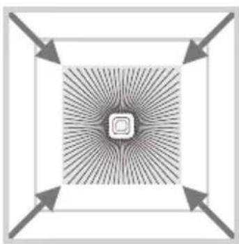
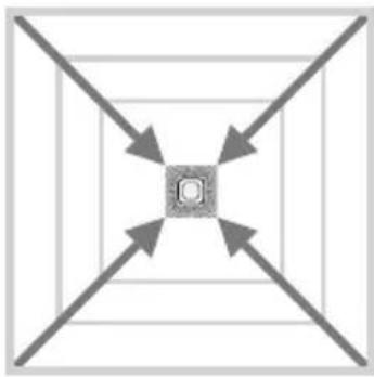
HF 360 DALI reach can be selected using service remote control RC 3 (see accessories). 1 or 2 detection directions can be masked out for adjustment to the room situation. An angle of coverage of 360° provides a max. reach of 8 m. The DUAL HF DALI
sensor has 2 special HF-sensors that detect movement from the ceiling in both directions. Reach is electronically selectable in either direction at the same time.
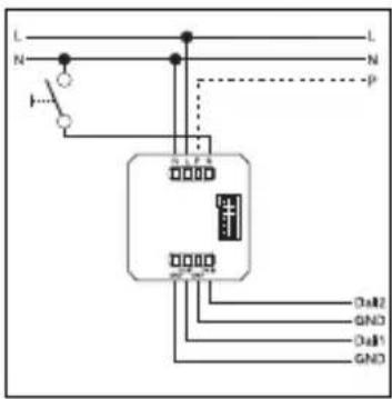
Electrical Installation/Automatic Mode
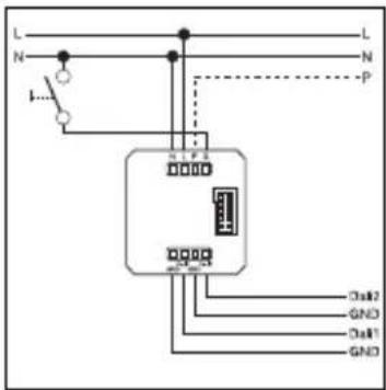
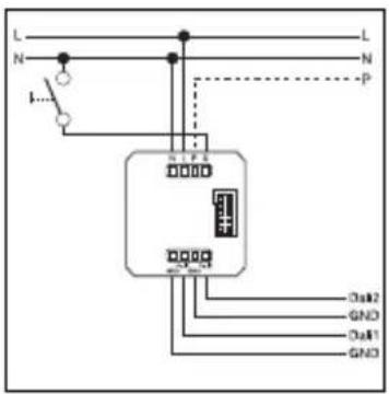
In selecting the wiring leads, it is important to meet the wiring regulations laid down in VDE 0100 (see Safety Precautions on page 18). The following applies to wiring presence detectors: Section 6 of
VDE 0100 520 permits the use of a multiple-conductor cable containing both the mains-voltage wires as well as the control lines (e.g. NYM 5 x 1.52) for the wiring between sensor and electronic bal-
last. The mains supply lead must be no greater than 10 mm in diameter. The clamping range of the mains terminal is designed for a maximum of 2 x 1.5 mm 2 or 1 x 2.5 mm 2 .

Technical Specifications
| Power supply: | 230 – 240 V/50 Hz | |
| DALI output 1: | 2-core DALI control cable / broadcast | |
| DALI output 2: | 2-core DALI control cable / broadcast | |
| Controllable DALI electr. ballasts: | 12 DALI electronic ballasts per output | |
| Square detection zones: | IR Quattro DALI | IR Quattro HD DALI |
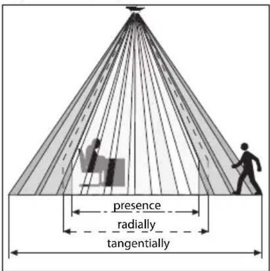
| Presence: | 4 x 4 m max. (16 sqm.) | 8 x 8 m max. (64 sqm.) |
| Radially: | 5 x 5 m max. (25 sqm.) | 8 x 8 m max. (64 sqm.) |
| Tangentially: | 7 x 7 m max. (49 sqm.) | 20 x 20 m max. (400 sqm.) |
| Angle of coverage: | HF 360 DALI | DUAL HF DALI |
| 360° with 140° aperture angle also through glass, wood and stud walls. 1 or 2 detection directions can be masked out for adjustment to the room situation. | see diagram on p. 20 also through glass, wood and stud walls | |
| Reach: | HF 360 DALI | DUAL HF DALI |
| 8 m max. all round, electronically and infinitely variable | 10 x 3 m max. in each direction electr. and infinitely variable | |
| Basic brightness : | 0 sec. – 30 min., 10 % | |
| Time setting: | 30 sec. – 30 min., IQ modeIQ mode (automatic adjustment to the usage profile) | |
| Installation height:(ceiling mounting) | 2.5 m – 8 m (IR Quattro DALI)2.5 m – 10 m (IR Quattro HD DALI) | |
| Installation site: | indoors | |
| Sensors: | 13 detection levels, 1760 switching zones (IR Quattro DALI)13 detection levels, 4800 switching zones (IR Quattro HDDALI) | |
| IP rating: | IP 20 (IP 54 with AP Box) | |
| Protection class: | II | |
| Temperature range: | 0°C to +40°C | |
Functions – Settings by DIP Switch
DIP 1
Normal mode / Test mode (NORM / TEST)
Test mode has priority over all other settings on the presence detector and serves the purpose of checking for proper working order as well for testing the detection zone. Irrespective of
ambient light level, the presence detector activates the light to stay 'ON' for approx. 8 sec. in response to movement in the room (blue LED flashes when movement is detected). All user-
selected potentiometer settings apply in normal mode. The presence detector can also be set by means of the blue LED without any load connected.
DIP 2
Semi-automatic mode (MAN) / fully automatic mode (AUTO)
Semi-automatic mode: (MAN)
The light now only switches 'OFF' automatically. Light is switched 'ON' manually. Light must be requested using the
button and stays 'ON' for the time set at the potentiometer. (pressing twice switches 'ON' for 4 hours).
Fully automatic mode: (AUTO)
The light automatically switches 'ON' and 'OFF' in relation to brightness when someone is present. Light can be switched 'ON' and 'OFF' manually at any time. This temporarily interrupts
the automatic switching function. Irrespective of the settings selected, light stays 'ON' for 4 hours after manually pressing the button twice or switches 'OFF' after manually pressing the
button once. Pressing the button before the 4 hours elapse returns the Presence Control IR Quattro to the normal operating mode.
DIP 3
Button/switch
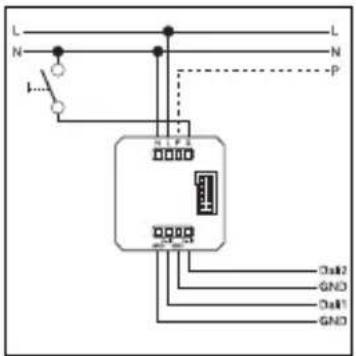
Tells the sensor how to interpret the incoming signal. Assigning external buttons/switches allows you to operate the detector as a semi-automatic unit and override it manually at any time.
■ Operation either by button or switch
■ Several buttons possible on one control input
■ Only use illuminated pushbutton with neutral conductor connected
■ Cable length between sensor and switch < 50 m
DIP 4
'ON'/'ON'-OFF' button
In the 'ON'-OFF' setting, the light can be switched 'ON' and 'OFF' manually at any time. In the 'ON'
setting, light can no longer be switched 'OFF' manually. The stay-'ON' time starts from the
beginning again each time the button is pressed.
DIP 5
Constant light 'ON'/'OFF'
Provides a constant level of brightness. Detector measures the prevailing level of daylight and activates sufficient artificial light to achieve the required
level of brightness. As daylight changes, the switched-in artificial lighting component is adjusted accordingly. In addition to the daylight component,
artificial light is also switched 'ON' and 'OFF' in relation to whether or not persons are present.
Functions – Settings by Potentiometer
Potentiometer ⑤
Twilight setting
The chosen response threshold can be infinitely varied from approx. 10 - 1000 lux.
Control dial turned fully clockwise: MAX daylight mode Control dial turned fully anti-clockwise: MIN night-time operation
Depending on the site of installation, the setting may need to be corrected by 1 – 2 marks on the scale.
| Examples of Use Brightness settings | |
| Night-time mode | min |
| Corridors, foyers | 1 |
| Stairs, escalators, moving walkways | 2 |
| Washrooms, toilets, switchrooms, canteens | 3 |
| Sales floor, kindergartens, nursery school rooms, sports halls | 4 |
| Work environments: Offices, conference and meeting rooms, precision assembly activities, kitchens | 5 |
| Working areas requiring good light:Laboratory, technical drawing, precision work | >=6 |
| Daylight modemax |
Note: Depending on the site of installation, the setting may need to be corrected by 1 – 2 marks on the scale. Brightness is measured directly at the sensor.
Potentiometer ⑥
Time setting
Stay-'ON' time for switching output 1 & 2 Setting 30 sec. – 30 min.
The chosen stay-'ON' time is infinitely variable from a minimum of approx. 30 sec. to a maximum of 30 min. Light is
calibrated after 3 min. When the threshold is exceeded, the sensor switches 'OFF' after the stay-'ON' time expires.
IQ mode
Turned fully clockwise: The stay-'ON' time is self-learning and adjusts dynamically to user
behaviour. The optimum time cycle is determined by means of a learning algorithm.
The shortest time is 2 min., the longest 20 min.
Potentiometer ⑦
Basic brightness (DIM/DALI version)
Provides basic illumination for the selected stay-'ON' time when ambient light falls below the selected brightness threshold that is set. This can be dimmed to 10% of maximum light intensity. As soon as a person enters the scene, the detector switches either to 100% light intensity (constant-lighting
controller 'OFF') or adjusts to the preselected brightness level (constant-lighting controller 'ON'). When no movement is being detected, the detector dims back to basic brightness after the stay-'ON' time expires. This is switched 'OFF' when stay-'ON' time (1 min. - 30 min.) has expired or the day-
light component is sufficient to exceed the selected level of brightness. In the 'ON' setting, the detector switches basic brightness 'ON' and 'OFF' as soon as the level of light falls below the brightness threshold.
Parallel-connected Configurations ⑭
When using several detectors, they must be connected to the same phase!

Master/master
The "P" input provides the capability of extending the zone movement is detected in.
It is not possible to wire two DALI power supply units through the "P" input as the DALI version only provides one input for "P". It is only possible to extend the detection
zone with a Presence Control PRO COM1/COM2 or DIM version.
Remote Control
Using the remote control (optional), functions can be conveniently activated from the floor.
Presence Control remote control unit:
Service remote control RC 3,
EAN No.: 4007841 000387
User remote control RC 5,
EAN No.: 4007841 592806
Troubleshooting
| Malfunction Cause Remedy | ||
| Light does not switch 'ON' | No supply voltageLux setting too lowNo motion detection | Check supply voltageSlowly increase lux setting until light switches 'ON'Ensure unobstructed sensor visionCheck detection zone |
| Light does not switch 'OFF' | Lux setting too highStay-'ON' time running outInterference from sources of heat, e.g.: fan heater, open doors and windows, pets, light bulb/halogen floodlight, moving objects (IR Quattro) | Reduce lux settingWait until stay-'ON' time elapses; reduce stay-'ON' time if necessaryUse stickers to mask out stationary sources of interference |
| Sensor switches 'OFF' in spite of persons being present | Stay-'ON' time too shortLight-level threshold too low | Increase stay-'ON' timeChange light threshold |
Troubleshooting
| Malfunction Cause Remedy | ||
| Sensor does not switch 'OFF' quickly enough | ■ Stay-'ON' time too long | ■ Reduce stay-'ON' time |
| Sensor does not switch 'ON' quickly enough when approached from the front | ■ Reach is reduced when approached from the front | ■ Install additional sensors■ Reduce distance between two sensors |
| Sensor does not switch 'ON' when persons are present in spite of it being dark | ■ Lux setting too low | ■ Sensor deactivated by switch/button?■ Semi-automatic mode?■ Increase light-level threshold |
| Sensor does not switch 'ON' selected basic brightness in spite of it being dark | ■ Sensor in semi-automatic mode■ Lux setting too low | ■ Sensor in fully automatic mode■ Increase light-level threshold |
GB
CE Declaration of Conformity
This product complies with
- Low Voltage Directive 2006/95/EC
- EMC Directive 2004/108/EC
- RoHS Directive 2002/95/EC.
Functional Warranty
This Steinel product has been manufactured with utmost care, tested for proper operation and safety and then subjected to random sample inspection. Steinel guarantees that it is in perfect condition and proper working order.
FUNCTIONAL
36 month
WARRANTY
The warranty period is 36 months and starts on the date of sale to the consumer. We will remedy defects caused by material flaws or manufacturing faults. The warranty will be met by repair or replacement of the defective parts at our own discretion. The warranty shall not cover damage to wear parts, damage or defects caused by improper treatment or maintenance. Further consequential damage to other objects shall be excluded.
Claims under the warranty will only be accepted if the unit is sent fully assembled and well-packed with a brief description of the fault, a receipt or invoice (date of purchase and dealer's stamp) to the appropriate Service Centre.
Repair service:
Our Customer Service Department will repair faults not covered by warranty or after the warranty period. Please send the product well packed to your nearest Service Centre.
F
Mode d'emploi
Cher client,

Potentiomètre ⑧


Potentiometer ⑧

Technische gegevens


Potenziometro ⑧

Dati tecnici


Potenciómetro ⑧

Datos técnicos

Potenciómetro ⑧

Dados técnicos

Potentiometer ⑧
Tekniska data
Grundljus (DIM/DALI version)

Potentiometer ⑧

Tekniske data
HF 360 DALI Dual HF DALI


Säädin ⑧

Tekniset tiedot

Potensiometer ⑧
Rekkevidden til HF 360 DALI kan innstilles elektro-nisk via service-fjernkontrollen RC 3 (se ekstraut-styr). 1 eller 2 registreringsretninger kan tildekkes for tilpasning til rommet. Med en registreringsvinkel på 360° oppnås en rekkevidde på maks. 8 m. DUAL
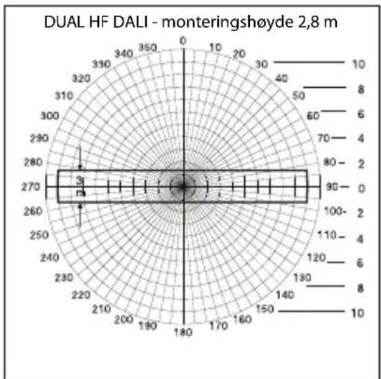
HF DALI sensoren har to spesielle HF-sensorer som overvåker begge retningene i en gang fra taket. Rekkevidden kan innstilles elektronisk i begge retninger samtidig.
Ποτενσιόμετρο ⑧

Τεχνικά δεδομένα

Potensiyometre ⑧
Teknik Özellikler


- POTI⑧
- GB OPERATING INSTRUCTIONS
- DEAR CUSTOMER
- SAFETY PRECAUTIONS
- ASSEMBLY/INSTALLATION ⑬ (SEE FIG. ON PAGE 2)
- SYSTEM COMPONENTS
- HOW IT WORKS / BASIC FUNCTION
- PRESENCE CONTROL PRO
- SETTINGS
- DETECTION ZONE
- POTENTIOMETER ⑧
- REACH SETTING (HF 360 DALI / DUAL HF DALI)
- ELECTRICAL INSTALLATION/AUTOMATIC MODE
- FUNCTIONS – SETTINGS BY DIP SWITCH
- DIP 1
- NORMAL MODE / TEST MODE (NORM / TEST)
- DIP 2
- SEMI-AUTOMATIC MODE (MAN) / FULLY AUTOMATIC MODE (AUTO)
- SEMI-AUTOMATIC MODE: (MAN)
- FULLY AUTOMATIC MODE: (AUTO)
- DIP 3
- BUTTON/SWITCH
- DIP 4
- ON'/'ON'-OFF' BUTTON
- DIP 5
- CONSTANT LIGHT 'ON'/'OFF
- FUNCTIONS – SETTINGS BY POTENTIOMETER
- POTENTIOMETER ⑤
- TWILIGHT SETTING
- POTENTIOMETER ⑥
- TIME SETTING
- IQ MODE
- POTENTIOMETER ⑦
- BASIC BRIGHTNESS (DIM/DALI VERSION)
- PARALLEL-CONNECTED CONFIGURATIONS ⑭
- MASTER/MASTER
- REMOTE CONTROL
- CE DECLARATION OF CONFORMITY
- FUNCTIONAL WARRANTY
- FUNCTIONAL
- F
- MODE D'EMPLOI
- CHER CLIENT
- POTENTIOMÈTRE ⑧
- POTENZIOMETRO ⑧
- POTENCIÓMETRO ⑧
- GRUNDLJUS (DIM/DALI VERSION)
- SÄÄDIN ⑧
- POTENSIOMETER ⑧
- ΠΟΤΕΝΣΙΌΜΕΤΡΟ ⑧
- POTENSIYOMETRE ⑧
Brand : STEINEL
Model : ST 008789
Category : Motion detector