
HL3000GM - Splitter SCHEPPACH - Free user manual and instructions
Find the device manual for free HL3000GM SCHEPPACH in PDF.
| Product Type | Hydraulic log splitter |
| Brand | Scheppach |
| Model | HL3000GM |
| Dimensions (L x W x H) | 1540 x 1140 x 2520 mm |
| Weight | 373 kg |
| Power supply | Three-phase electric motor 400 V~ / 50 Hz or PTO shaft (540 rpm) |
| Input power (P1) | 5500 W |
| Output power (P2) | 4500 W |
| Max. splitting force | 30 t |
| Cylinder stroke | 948 mm |
| Forward speed | 12.5 cm/s |
| Return speed | 6.7 cm/s |
| Allowable log length | 560 - 1100 mm |
| Allowable log diameter | 100 - 400 mm |
| Oil tank capacity | 30 l |
| Operating mode | S6 40% (intermittent periodic operation) |
| Sound pressure level (L_pA) | 55 dB (uncertainty 3 dB) |
| Sound power level (L_WA) | 75 dB (uncertainty 3 dB) |
| Safety | Two-hand control, restart protection, automatic shutdown in case of power failure |
| Maintenance | Change hydraulic oil every 250 h, transmission oil every 250 h or 6 months |
| Warranty | Legal (material or manufacturing defects) |
Frequently Asked Questions - HL3000GM SCHEPPACH
User questions about HL3000GM SCHEPPACH
0 question about this device. Answer the ones you know or ask your own.
Ask a new question about this device
Download the instructions for your Splitter in PDF format for free! Find your manual HL3000GM - SCHEPPACH and take your electronic device back in hand. On this page are published all the documents necessary for the use of your device. HL3000GM by SCHEPPACH.
USER MANUAL HL3000GM SCHEPPACH
natural_image
Industrial machine tool with articulated arms and wheels, no visible text or symbols
| DE | MeterholzspalterOriginalbetriebsanleitung | 8 |
| GB | Metre log splitterTranslation of original instruction manual | 21 |
| FR | Fendeur de bûches d'un mètreTraduction des instructions d'origine | 32 |
| IT | Spaccalegna per legna da catastaLa traduzione dal manuale di istruzioni originale | 44 |
| NL | Houtklover per meterVertaling van de originele gebruikshandleiding | 56 |
| ES | Cortadora de troncos por metrosTraducción del manual de instrucciones original | 68 |
| PT | Rachador de lenha curtaTradução do manual de operação original | 80 |
| CZ | Štípačka metrového dřevaPřeklad originálního návodu k obsluze | 92 |
| SK | Štiepačka na metrové drevoPreklad originálneho návodu na obsluhu | 103 |
| HU | Kompakt rönkhasítóEredeti használati utasítás fordítása | 114 |
| PL | Rozdzielacz drewna metrowegoTłumaczenie oryginalnej instrukcji obsług | 125 |
| HR | Kompaktan cjepač drvaPrijevod originalnog priručnika za uporabu | 137 |
| SI | Cepilec metrskega lesaPrevod originalnih navodil za uporabo | 148 |
| EE | MeetripuidulõhkujaOriginaalkäitusjuhendi tõlge | 159 |
| LT | Nustatyto dydžio malkų skaldyklėOriginalios naudojimo instrukcijos vertimas | 170 |
| LV | Metriskas malkas skaldītājsOriginālās lietošanas instrukcijas tulkojums | 181 |
| SE | MetervedklyvÖversättning av original-bruksanvisning | 192 |
| FI | MetrihalkaisukoneKäännös alkuperäisestä käyttöohjeesta | 203 |
| DK | BrændekløverOversættelse fra den oprindelige betjeningsvejledning | 214 |
| NO | Meter vedkløyverOversettelse av den originale brukerveiledningen | 225 |
| BG | Машина за цепене на дърваПревод на оригиналното ръководство за експлоатация | 236 |
| GR | Σχίστης ξύλων μικρού μήκουςΜετάφραση του πρωτοτύπου των οδηγιών χρήσης | 248 |
| RO | Despicător vertical de lemneTraducere din manualul de exploatare original | 260 |
| RS | Uređaj za cepanje drveta na metarPrevod originalnog uputstva za upotrebu | 272 |
| TR | Odun yarma makinesiOrijinal kullanım talimatı çevirisi | 283 |
1

2


natural_image
Technical line drawing of a mechanical lifting device with no visible text or symbols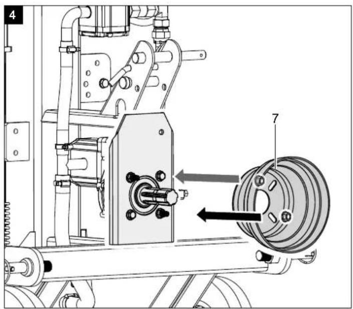

natural_image
Mechanical assembly diagram showing a motor drive mechanism with no visible text or symbols


natural_image
Technical line drawing of a mechanical component with circular and rectangular features (no text or symbols)
natural_image
Technical line drawing of a screwdriver and its internal component (no text or symbols)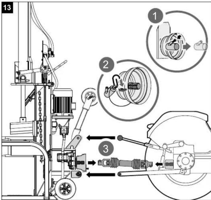
natural_image
Technical line drawing of a mechanical assembly with an inset showing a close-up of a shaft and linkage mechanism (no text or symbols present)


natural_image
Technical line drawing of a mechanical assembly with pipes and a central cylindrical component (no text or symbols)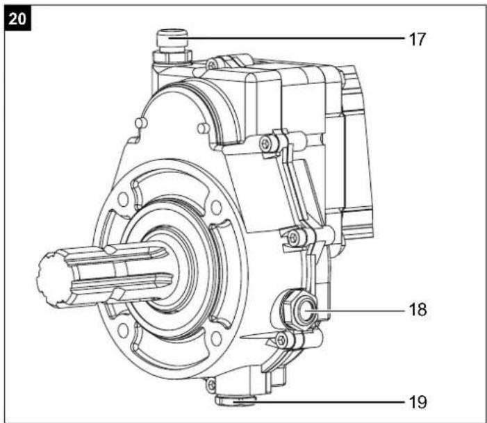
Günzburger Straße 69
D-89335 Ichenhausen
Verehrter Kunde
Explanation of the symbols on the device
Symbols are used in this manual to draw your attention to potential hazards. The safety symbols and the accompanying explanations must be fully understood. The warnings themselves will not rectify a hazard and cannot replace proper accident prevention measures.
 | Read the handbook before commissioning | |
 | Use safety shoes | |
 | Use work gloves | |
 | Use hearing protection and safety goggles | |
 | Use safety helmet | |
 | No smoking in the working area | |
 | Do not let hydraulic oil run onto the floor | |
 | Keep the work area orderly! Disorder can lead to accidents! | |
 | Dispose of used oil properly (on-site waste oil collection point). Dumping used oil in the soil or mixing it with waste is prohibited. | |
 | Do not remove any jammed trunks with your hands. | |
 | Removing or modifying protective or safety equipment is prohibited. | |
 | Attention! Before starting repair, maintenance and cleaning work, switch off the engine and unplug the mains plug. | |
 | Danger of cuts and crushing; never touch dangerous areas when the splitting blade is moving. | |
 | High voltage, risk of death! | |
 | Machine may only be operated by one person! | |
 | Loosen the bleeder screw about 2 turns before starting work. Close before transport. | |
 | Caution! Moving tools! | |
 | Do not transport the device lying down! | |
 | No entry for unauthorised persons | |
 | Two operating speeds:1. Low speed and full splitting force2. High speed and reduced splitting force | |
| △ Attention! | We have marked points in these operating instructions that impact your safety with this symbol | |
 | The product complies with the applicable European directives. | |
 | The product complies with the applicable Serbian directives. | |
Table of contents: Page:
- Introduction......24
- Device description....24
- Scope of delivery....24
- Proper use....24
- General safety instructions....25
- Additional safety instructions.... 25
- Technical data 26
- Unpacking 26
- Assembly / Before commissioning 26
- Start-up 27
- Electrical connection 29
- Cleaning 29
- Transport 29
- Storage....29
- Maintenance....30
- Disposal and recycling 30
- Troubleshooting....31
- Declaration of conformity 295
1. Introduction
Manufacturer:
Scheppach GmbH
Günzburger Straße 69
D-89335 Ichenhausen
Dear Customer
We hope your new device brings you much enjoyment and success.
Note:
In accordance with the applicable product liability laws, the manufacturer of this device assumes no liability for damage to the device or caused by the device arising from:
- Improper handling
- Failure to comply with the operating instructions.
• Repairs carried out by third parties, unauthorised specialists
• Installing and replacing non-original spare parts - Improper use
- Failure of the electrical system in the event of the electrical regulations and VDE provisions 0100, DIN 57113 / VDE 0113 not being observed
Note:
The operating manual is part of this product. It includes important instructions for the safe, proper and economic operation of the product, for avoiding danger, for minimising repair costs and downtimes and for increasing the reliability and extending the service life of the product. In addition to the safety instructions in this operating manual, you must also observe the regulations applicable to the operation of the product in your country. Familiarise yourself with all operating and safety instructions before using the product. Only operate the product as described and for the specified areas of application. Keep the operating manual in a good place and hand over all documents when passing the product on to third parties.
2. Device description
- Cylinder
- Control handle
- Additional transport wheel
- Engine
- Chain
- Trunk lifter
- Cardan shaft protective cap
- Three-point mounting
- Transport wheels
- Return lever
- Riving knife
- Combination switch/plug
-
Retainer arm
-
Support plate
- Cardan shaft end firewood splitter
- Drive vehicle cardan shaft end
- Oil filling opening
- Sight glass
- Oil drain screw
3. Scope of delivery
A. Splitter
B. Retainer arm
C. Trunk lifter
D. Retainer hook
E. Cardan shaft protective cap
F. Accessory bag (a,b,c,d,e,f)
G. Additional transport wheel
H. Operating manual
4. Proper use
The machine may only be used in the intended manner. Any use beyond this is improper. The user/operator, not the manufacturer, is responsible for damages or injuries of any type resulting from this.
An element of the intended use is also the observance of the safety instructions, as well as the assembly instructions and operating information in the operating manual.
Persons who operate and maintain the machine must be familiar with it and must be informed about potential dangers.
In addition, the applicable accident prevention regulations must be strictly observed.
Other general occupational health and safety-related rules and regulations must be observed.
The liability of the manufacturer and resulting damages are excluded in the event of modifications of the machine.
The machine may only be operated with original parts and original accessories from the manufacturer.
The safety, operating and maintenance specifications of the manufacturer, as well as the dimensions specified in the technical data, must be observed.
- The hydraulic log splitter can only be used when standing and timbers may only be split in the direction of the grain. The dimensions of the timbers to be split:
Wood length 110 cm
∅ min. 10 cm, max. 40 cm
- Never split wood horizontally or against the grain.
- The manufacturer's safety, operating and maintenance specifications as well as the dimensions given in the technical data must be observed.
- Relevant accident prevention regulations and other generally recognized safety and technical rules must also be observed.
- The machine may only be used, maintained or repaired by persons who are familiar with it and have been informed of the dangers. The manufacturer shall not be liable for damage resulting from unauthorised changes to the machine.
- The machine may only be operated with original accessories and original tools from the manufacturer.
- Any use beyond this is improper use. The manufacturer is not responsible for the resulting damages; the user solely bears the risk.
Please note that our equipment was not designed with the intention of use for commercial or industrial purposes. We assume no guarantee if the device is used in commercial or industrial applications, or for equivalent work.
5. General safety instructions
WARNING: When using power tools, the basic safety precautions below must be followed in order to reduce the risk of fire, electric shock, and personal injury. Please read all instructions before working with this tool.
- Observe all safety information and danger notices on the machine.
- Ensure that all of the safety information and danger notices on the machine are complete and in legible condition.
- The safety equipment on the machine must not be disassembled or made unusable.
- The safety equipment on the machine must not be disassembled or made unusable.
- Check mains connection cables. Do not use faulty connection cables.
- Check for correct function of the two-hand control before commissioning.
- The operating personnel must be at least 18 years of age. Trainees must be at least 16 years of age and may only work on the machine under supervision.
- Wear work gloves when working.
- Caution when working: Danger of injury for fingers and hands due to the splitting tool.
- Use suitable aids to support the splitting of heavy or bulky parts.
- Modification, adjustment and cleaning work, as well as maintenance and rectification of faults may only be carried out when the engine is switched off. Pull out the mains plug!
- Installation, repairs and maintenance work on the electrical equipment may only be carried out by electricians.
- All protective and safety equipment must be reassembled immediately after repair, maintenance is completed.
- Switch off the engine when leaving the work station. Pull out the mains plug!
6. Additional safety instructions
- The log splitter may only be operated by a single person.
- Wear protective equipment (safety goggles/visor, gloves, safety shoes) to safeguard yourself against possible injury.
- Never split trunks that contain nails, wire or other objects.
- Wood that has already been split and wood chippings create a hazardous work area. There is a danger of tripping, slipping or falling. Always keep the work area orderly.
- Never place your hands on moving parts of the machine when it is switched on.
- Only split wood with a maximum length of 110 cm.
Warning! This power tool generates an electromagnetic field during operation. This field can impair active or passive medical implants under certain circumstances. In order to prevent the risk of serious or deadly injuries, we recommend that persons with medical implants consult with their physician and the manufacturer of the medical implant prior to operating the power tool.
Residual risks
The machine has been built according to the state-of-the-art and the recognised technical safety requirements. However, individual residual risks can arise during operation.
- Danger of injury for fingers and hands from the splitting tool in the event of improper guiding or support of the wood.
- Injuries due to the workpiece being ejected at high speed due to improper holding or guiding.
- Hazard due to electrical power with the use of improper electrical connection cables.
• Furthermore, despite all precautions having been met, some non-obvious residual risks may still remain. - Residual risks can be minimised if the “Safety instructions” and the “Proper use” are observed along with the whole of the operating instructions.
- Health hazard due to electrical power, with the use of improper electrical connection cables.
- Before performing setting or maintenance work, release the start button and pull out the mains plug.
- Avoid accidental starting of the machine: the operating button may not be pressed when inserting the plug in an outlet.
- Use the tool that is recommended in this operating manual. This is how to ensure that your machine provides optimum performance.
- Keep your hands away from the working area when the machine is in operation.
7. Technical data
| HL2200GM | HL3000GM | |
| Drive | PTO shaft + Electric motor | |
| Engine | 400 V~ / 50 Hz | |
| Rated input P1 | 5100 W | 5500 W |
| Power output P2 | 4000 W | 4500 W |
| Operating mode | S6 40% | |
| PTO / motor speed | 540 rpm1400 rpm | |
| Phase inverter | yes | |
| Dimensions L x W x H | 1540 x 1140 x 2520 mm | |
| Wood length min./max. | 560 - 1100 mm | |
| Wood diameter min./max. | 100 - 400 mm | |
| Power max. | 22 t | 30 t |
| Cylinder stroke | 948 mm | |
| Forward speed | 10.5 cm/s | 12.5 cm/s |
| Return speed | 7.5 cm/s | 6.7 cm/s |
| Oil quantity | 24 l | 30 l |
| Weight | 319 kg | 373 kg |
Subject to technical changes!
Noise
⚠ Warning: Noise can have serious effects on your health. If the machine noise exceeds 85 dB, please wear suitable hearing protection.
Noise data
| Sound power level L_WA | 75 dB |
| Sound pressure level L_pA | 55 dB |
| Uncertainty K_WA/pA | 3 dB |
* Operating mode S6 40% is an uninterrupted, periodic mode. The mode comprises of a start-up period, a time with constant load and an idle time. The operating time is 10 mins, the relative duty cycle is 40% of the operating time.
Pressure:
The performance level of the built-in hydraulic pump can reach a brief pressure level for a splitting force of up to 22/30 tons. In the basic setting, hydraulic splitters are set at the factory to an approx. 10% lower output level. For safety reasons, the basic settings must not be changed by the user.
Please note that external circumstances such as operating and ambient temperature, air pressure and moisture affect the viscosity of the hydraulic oil. In addition, manufacturing tolerances and maintenance errors can affect the reachable pressure level.
8. Unpacking
Open the packaging and carefully remove the device. Remove the packaging material, as well as the packaging and transport safety devices (if present). Check whether the scope of delivery is complete.
Check the device and accessory parts for transport damage.
In the event of complaints the carrier must be informed immediately. Later claims will not be recognised.
If possible, keep the packaging until the expiry of the warranty period.
Familiarise yourself with the device by means of the operating manual before using for the first time.
With accessories as well as wearing parts and replacement parts use only original parts. Spare parts can be obtained from your specialist dealer.
When ordering please provide our article number as well as type and year of manufacture for your equipment.
ATTENTION!
The device and the packaging material are not children's toys! Do not let children play with plastic bags, films or small parts! There is a danger of choking or suffocating!
9. Assembly / Before commissioning
9.1 Fitting the three-point bolts (Accessory bag A) (Fig. 3)
Insert the threaded bolts through the holes provided and fix each one from the other side with an M22 nut.
Place the cardan shaft protective cover on the protruding grub screws on the cardan shaft and secure it with the two M10 nuts.
Connect the splitter to the mains. Observe the rotational direction of the motor. Lower the two control handles until the cylinder latches into the guide. Insert the two L-pins (C) to secure the cylinder to the firewood splitter. Secure the L-pins in the spring lugs. After that, drive the splitting blade to the top position and remove the support.
Keep the prop in a good place as it will be needed for transporting the splitter.
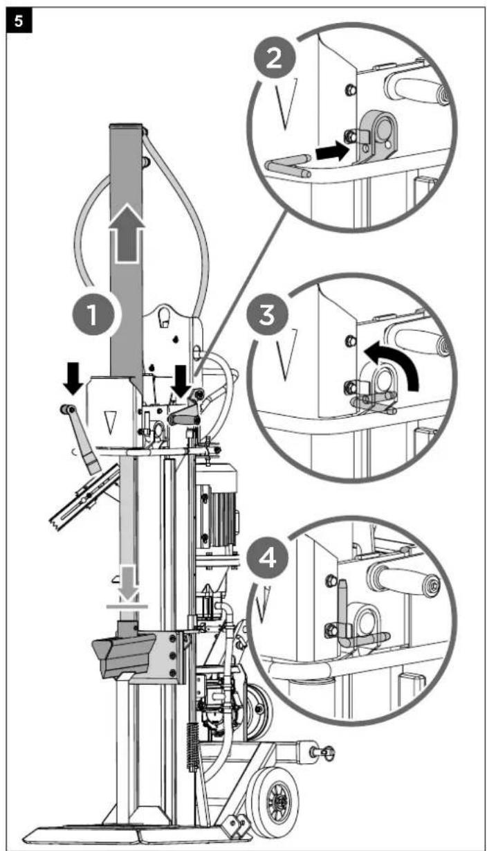
9.4 Fitting the retaining arm (13) (Accessory bag D) (Fig. 7)
Secure the retaining arm with an M10x40 hexagon screw, two washers and a nut.
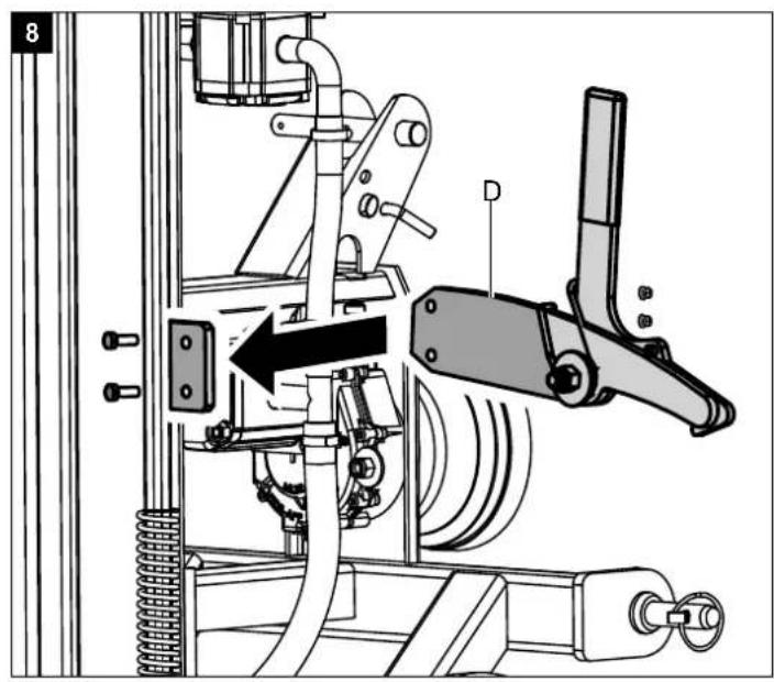
9.5 Fitting the retaining hook (D) (Accessory bag E) (Fig. 8)
Attach the retaining hook to the frame with 2 hexagon screws and 2 nuts.
9.6 Fitting the trunk lifter (accessory bag F) (Fig. 9)
Fasten the trunk lifter to the retaining lug with a hexagon screw M16x100. Attach the chain to the splitting blade.
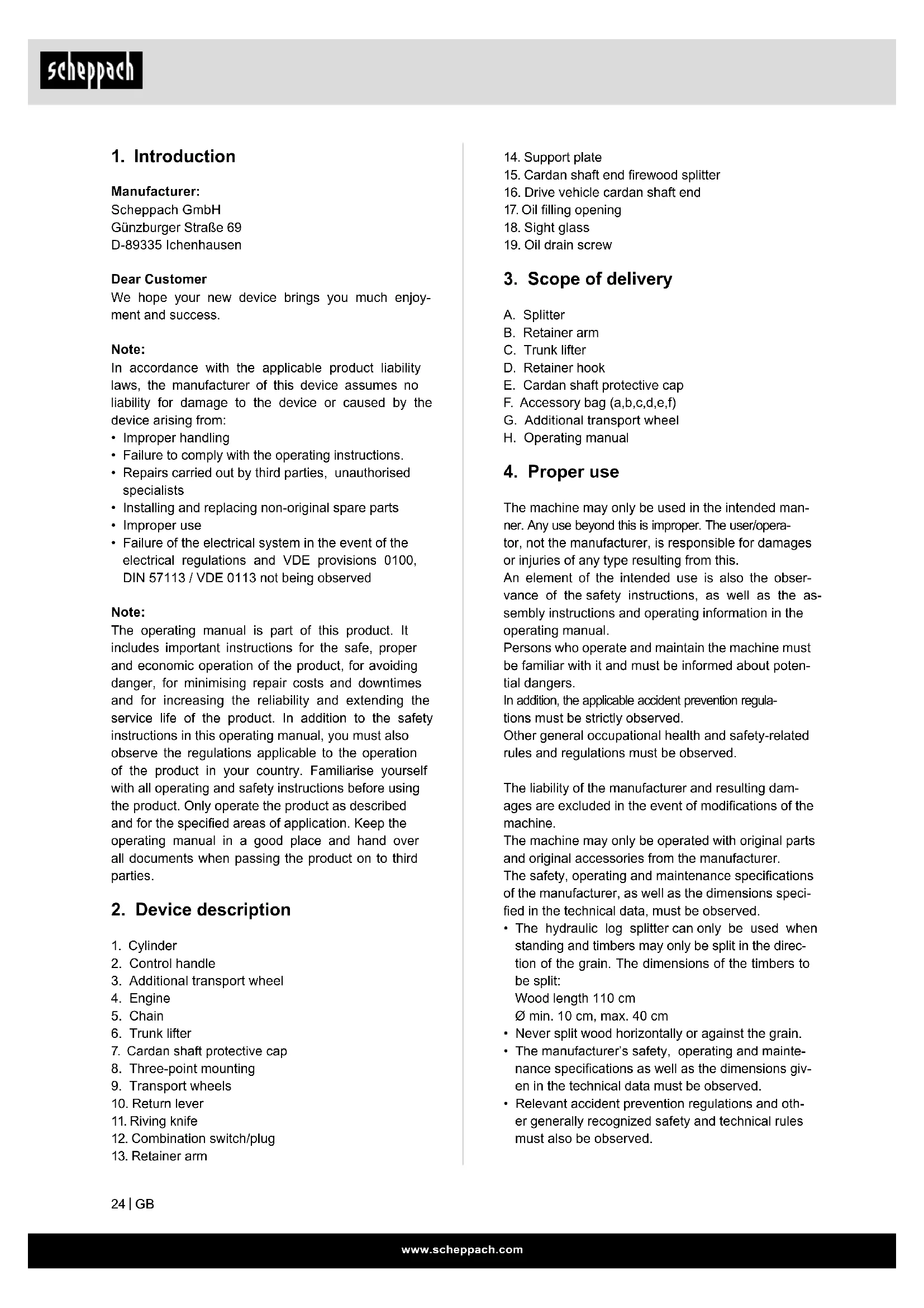
Fitting an additional transport wheel (Fig. 10)
Attach the transport wheel as shown in Fig. 10. Fix the wheel in the upper hole with the locking pin (10a) when working with the splitter. Fix the wheel in the lower hole during transport.
ATTENTION!
Always make sure the device is fully assembled before commissioning!
10. Start-up
Make sure that the machine is installed completely and properly. Before each use, always check:
- the connection cables for defective areas (cracks, cuts and the like),
• The machine for possible damage,
• Whether all screws are tightened,
• The hydraulics for leaks and - The oil level
Check the oil level (fig. 13)
The hydraulic system is a closed system with an oil tank, oil pump and control valve. Check the oil level regularly before commissioning. An oil level that is too low can damage the oil pump. The oil level must be within the middle mark on the oil dipstick. The splitting column must be retracted before the check, the machine must be level. Screw in the oil dipstick fully, to measure the oil level.
E-Motor
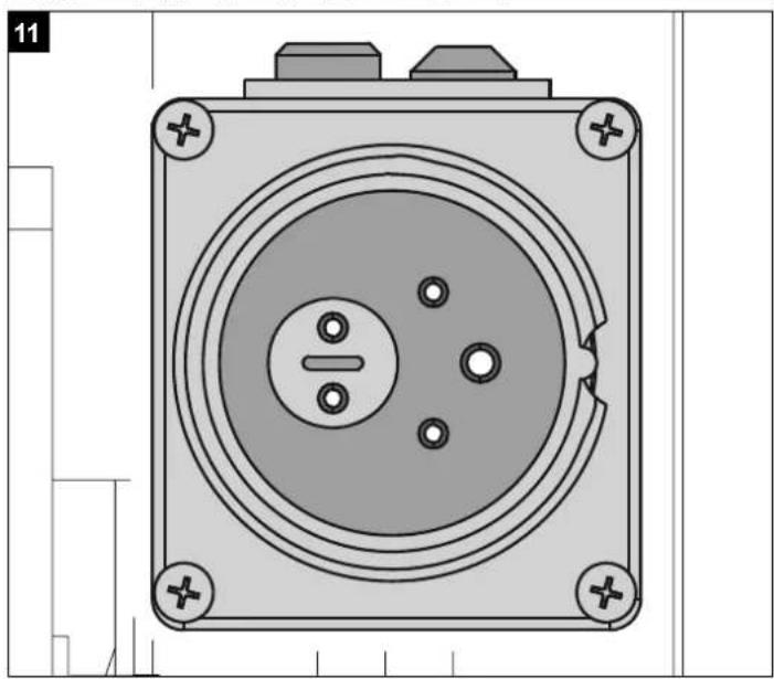
Check the running direction of the motor. If the splitting arm is not in the upper position, move the splitting blade to the upper position using the return bow or handles. If the splitting arm is already in the top position, activate the splitting mechanism by moving the two levers downwards. This moves the splitting arm downwards. If the splitting blade does not move despite actuating the handles or the return bow, switch off the machine immediately. Turn the pole reversing unit in the plug-in unit (Fig. 11 + 12) to change the direction of rotation of the motor.
Never allow the motor to run with the wrong direction of rotation! This will inevitably lead to the destruction of the pump system and no warranty claim can be made for this.
Functional check
Carry out a functional check before each use.
Action:
Result:
| Press both handles downwards. | Splitting blade goes down - until approx. 20 cm above the table. |
| Release one handle at a time | The splitting blade remains in the selected position. |
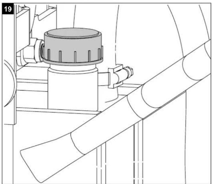
Attention!
Loosen the filler plug (Fig. 19) before commissioning.
Never forget to loosen the filler plug!
Otherwise, the air in the system will be repeatedly compressed and depressurised, which will destroy the seals of the hydraulic circuit and the log splitter will no longer be usable. In this case, the seller and the manufacturer disassociate themselves from any warranty claims.
Switching on/off (12)
Press the green button to switch on.
Press the red button to switch off.
Note: Before each use, always check the function of the on-off unit by switching it on and off once.
Restart protection in the event of a power interruption (zero-voltage release)
In the event of a power failure, unintentional unplugging of the plug or a defective fuse, the device switches off automatically. To switch it back on again, press the green button on the switch unit again.
Cardan shaft
- Before connecting the machine to the three-point hitch of the drive vehicle, ensure that the weight of the machine is suitable for the drive vehicle. The weight of the machine can be found on the manufacturer's rating plate.
- The cardan shaft may only be connected when the tractor engine is switched off.
- Only use approved cardan shafts that are suitable for use with the log splitter. The cardan shaft must also be equipped with all safety devices, which must be in good condition.
- Do not stand near the cardan shaft when it is in operation.
- Ensure that the speed on the tractor does not exceed the number specified on the rating plate, max. 540 rpm.
- Before carrying out maintenance work or if the riv- ing knife has become jammed, first disconnect the machine from the tractor and switch off the tractor.
Attaching splitter to drive vehicle
(fig. 13 + 14)
- Drive the drive vehicle backwards to the log splitter. Position the lower mounting arms close enough to the mounting pins of the firewood splitter.
- Apply the parking brake of the drive vehicle and switch off the engine. Block the rear wheels on both sides with wedges or other suitable objects.
- Remove the dust cover (1) and attach it to the cardan shaft protective cover (2).
- Lower the lower mounting arms to the support pins of the firewood processor and secure them with the locking pins. (3)
- Position the upper mounting arm in the bracket and align it with the holes in the bracket. Insert the hanger pin to lock the upper mounting arm.
- The cardan shaft end of the gearbox has a diameter of 34.8 mm and a connection with 6 teeth (standard category 1 cardan).
- Slide the cardan drive shaft over the cardan shaft end on the gearbox and on the drive vehicle. Press in the spring pins located at both ends of the cardan shaft drive. Push the drive shaft further over the ends of the cardan shaft until the spring pins spring out and engage in the teeth of the end of the cardan shaft.
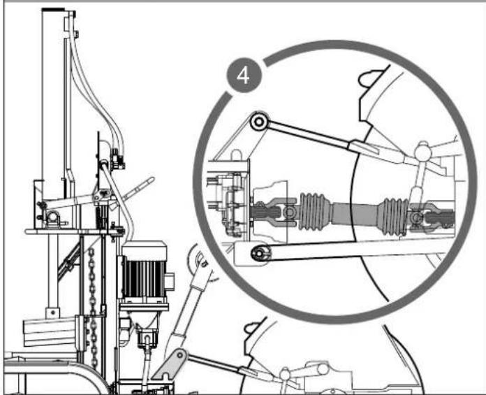
- Align the cardan shaft
Viewed from above and from the side of the shaft, the cardan shaft end on the firewood splitter (15) and the cardan shaft end on the drive vehicle (16) must be aligned parallel. The angles of the universal joints ( ) must be as small as possible. - Secure the safety chain of the cardan shaft drive to a fixed part of the firewood processor and the drive vehicle to prevent the protective device from turning.
Check the running direction of the drive vehicle's cardan shaft. If the splitting arm is not in the upper position, move the splitting blade to the upper position using the return bow or handles.
If the splitting arm is already in the top position, activate the splitting mechanism by moving the two levers downwards. This moves the splitting arm downwards. If the splitting blade does not move despite actuating the handles or the return bow, stop the cardan shaft drive and change its direction of rotation.
Never allow the cardan shaft drive to run with the wrong direction of rotation! This will inevitably lead to the destruction of the pump system and no warranty claim can be made for this.
Using the guard arm (Fig. 15)
The height of the guard arm can be set at various stages to suit the length of the wood.
Splitting (Fig. 16 + 17)
- If the outside temperature is below 5°C, allow the machine to idle for approx. five minutes so that the hydraulic system reaches operating temperature.
Stand the wood upright under the splitting blade - When you press both adjustment levers down, the splitting blade moves downwards and splits the wood.
- Only split logs that have been sawn off straight.
- Split wood vertically.
- Never split horizontally or across the grain!
- Wear suitable gloves and safety shoes when splitting wood.
- If the wood is extremely overgrown, split the trunks from the outline.
Attention: Certain types of wood can come under a lot of tension during splitting and crack abruptly. - Pull out jammed wood against the splitting direction or remove it by moving the riving knife upwards. △ Warning: Danger of crushing for fingers and hands!
Attention: The splitting blade is very sharp. Danger of injury!
Operation of the trunk lifter (6)
General information about the trunk lifter:
- The chain of the trunk lifter may only be attached to the splitting blade using the last link for safety reasons.
- Ensure that no other people are present in the working range of the trunk lifter
Operation of the trunk lifter:
- Release the retaining hook of the trunk lifter so that the lifting tube can run freely.
- Move the splitting blade down until the lifting tube of the trunk lifter lies completely on the floor.
- In this position, you can roll the trunk to the split onto the lifting tube.
- Push the return bow down and let the splitting blade move up.
(Caution! Do not stand in the working range of the trunk lifter! Danger of injury!) - Now align the trunk, press it against the holding mandrel and split it.
- Then remove the split wood and move the riving knife and thus the trunk lifter down again.
- A new log can now be rolled onto the trunk lifter.
(The trunk must lie in the area between the two fixing points)
(Refer to: Working instructions)
Resetting the trunk lifter.
This is used as a second guard arm when not using the trunk lifter. To do this, the arm is raised until it engages on the retaining hook.
Transport position of the trunk lifter:
Guide the trunk lifter up by hand until it latches into place.
Observe these instructions to ensure that you can work quickly and safely
11. Electrical connection
The electrical motor installed is connected and ready for operation. The connection complies with the applicable VDE and DIN provisions.
The customer's mains connection as well as the extension cable used must also comply with these regulations.
Damaged electrical connection cable
The insulation on electrical connection cables is often damaged.
This may have the following causes:
- Pressure points, where connection cables are passed through windows or doors.
- Kinks where the connection cable has been improperly fastened or routed.
- Places where the connection cables have been cut due to being driven over.
- Insulation damage due to being ripped out of the wall outlet.
- Cracks due to the insulation ageing.
Such damaged electrical connection cables must not be used and are life-threatening due to the insulation damage.
Check the electrical connection cables for damage regularly. Ensure that the connection cables are disconnected from electrical power when checking for damage.
Electrical connection cables must comply with the applicable VDE and DIN provisions. Only use connection cables with the designation H07RN.
The printing of the type designation on the connection cable is mandatory.
For single-phase AC motors, we recommend a fuse rating of C 16A or K 16A for machines with a high starting current (from 3000 watts)!
3-phase motor 400 V \~/ 50 Hz
Mains voltage 400 V\~ / 50 Hz.
Mains power connection and extension leads must be 5-core = 3 P + N + SL. - (3/N/PE).
Extension cables must have a minimum cross section of 1.5mm^2 .
The mains power connection must be protected with a max. 16 A fuse.
When connecting to the mains or in the event of the machine being moved to another location, the turning direction must be checked. It may be necessary to change the polarity.
Turn the pole changing device in the device connector.
12. Cleaning
Attention!
Disconnect the mains plug before carrying out any cleaning work.
We recommend that you clean the device directly after every use.
Wipe swarf and dust off the machine from time to time with a cloth.
Clean the device at regular intervals using a damp cloth and a little soft soap. Do not use any cleaning products or solvents; they could attack the plastic parts of the device. Make sure that no water can penetrate the device interior.
13. Transport
The firewood splitter can be easily transported using the 3-point attachment on the drive vehicle.
Before transporting the firewood splitter, place it in the transport position. To do this, move the riving knife downwards until it rests on the metal support.
Then remove both L-pins and move the hydraulic cylinder down into the transport position by pressing the return bow downwards.
Make sure there is sufficient manoeuvring space when driving, e.g. when turning, parking and at junctions.
Before transport, ensure that the firewood splitter is properly and securely attached to the drive vehicle and that the cardan shaft has been disassembled.
Never transport the firewood splitter with the cardan shaft drive connected.
Make sure that the firewood splitter is raised high enough to pass obstacles during transport.
14. Storage
Store the device and its accessories in a dark, dry and frost-free place that is inaccessible to children.
The optimum storage temperature lies between 5 and 30 °C.
Store the tool in its original packaging.
Cover the tool to protect it from dust or moisture.
Store the operating manual with the tool.
15. Maintenance
Attention!
Disconnect the mains plug before carrying out any maintenance work. Ensure that the cardan shaft is not connected to the drive vehicle.
When do I change the oil?
Initial oil change after 50 operating hours, then every 250 operating hours.
Oil change (Fig. 18)
Place the firewood splitter on a slightly raised surface (e.g. Euro pallet). Set a sufficient container (min. 30 litres) under the drain screw on the splitting column.
Open the drain screw and carefully allow the oil to run into the container.
Open the filler plug on the top of the splitting column so that the oil can drain off better.
Reinsert the drain screw with seal and tighten securely.
Top up with new hydraulic oil. (contents: see technical data) and check the oil level with the oil dipstick.
After changing the oil, operate the firewood splitter several times without actually splitting.
Attention! Do not allow any dirt particles to enter the oil container.
Dispose of the used oil properly at a local used oil collection point. Dumping used oil in the soil or mixing it with waste is prohibited.
We recommend oil from the HLP 32 range.
Changing the gearbox oil (Fig. 20)
The gearbox is filled with SAE90 gear oil at the factory. Drain the gear oil after the first 50 operating hours and replace it with new oil as specified.
The next oil change should then be carried out every 250 operating hours or every six months, whichever comes first.
- Disassemble the cardan shaft protective cover and set a sufficiently large container under the gearbox.
- First open the oil drain screw (19) and then the oil filler opening (17) and drain the oil completely.
- Close the oil drain screw with a new seal and fill new SAE90 gear oil into the filler opening using a funnel until the lower edge of the sight glass (18) is almost covered with oil.
Check the oil level every 8 hours. The oil level is correct when the lower edge of the sight glass (18) is almost covered with oil.
Hydraulic system
The hydraulic system is a closed system with an oil tank, oil pump and control valve.
The factory-completed system must not be changed or tampered with.
Check the oil level regularly.
An oil level that is too low will damage the oil pump, Regularly check hydraulic connections and screw connections for leaks - retighten if necessary.
Connections and repairs
Connections and repair work on the electrical equipment may only be carried out by electricians.
Please provide the following information in the event of any enquiries:
• Type of current for the motor
- Machine data - type plate
- Motor data - type plate
Service information
With this product, it is necessary to note that the following parts are subject to natural or usage-related wear, or that the following parts are required as consumables.
Wearing parts*: Riving knife, hydraulic oil, gear oil
* may not be included in the scope of delivery!
Spare parts and accessories can be obtained from our Service Centre. To do this, scan the QR code on the front page.
16. Disposal and recycling
Notes for packaging


The packaging materials are recyclable. Please dispose of packaging in an environmentally friendly manner.
Notes on the electrical and electronic equipment act (ElektroG)

Waste electrical and electronic equipment does not belong in household waste, but must be collected and disposed of separately!
- Old batteries or rechargeable batteries that are not permanently installed in the old unit must be removed before handing them in! Their disposal is regulated by the battery act.
- Owners or users of electrical and electronic devices are legally obliged to return them after use.
- The end user is responsible for deleting their personal data from the old device being disposed of!
- The symbol of the crossed-out dustbin means that waste electrical and electronic equipment must not be disposed of with household waste.
- Waste electrical and electronic equipment can be handed in free of charge at the following places:
- Public disposal or collection points (e.g. municipal works yards)
- Points of sale of electrical appliances (stationary and online), provided that dealers are obliged to take them back or offer to do so voluntarily.
- Up to three waste electrical devices per type of device, with an edge length of no more than 25 centimetres, can be returned free of charge to the manufacturer without prior purchase of a new device from the manufacturer or taken to another authorised collection point in your vicinity.
-
Further supplementary take-back conditions of the manufacturers and distributors can be obtained from the respective customer service.
-
If the manufacturer delivers a new electrical appliance to a private household, the manufacturer can arrange for the free collection of the old electrical appliance upon request from the end user. Please contact the manufacturer's customer service for this.
- These statements only apply to devices installed and sold in the countries of the European Union and which are subject to the European Directive 2012/19/EU. In countries outside the European Union, different regulations may apply to the disposal of waste electrical and electronic equipment.
17. Troubleshooting
The following table shows fault symptoms and describes remedial measures in the event of your machine failing to work properly. If you cannot localise and rectify the problem with this, please contact your service workshop.
| Fault Possible cause Remedy | ||
| The hydraulic pump does not start | No voltage Check whether the lines have a power supply | |
| The motor thermostat has switched itself off | Switch the thermostat inside the motor housing back on | |
| The column does not move downwards | Low oil level Check the oil level and top up | |
| One of the levers is not connected Check the attachment of the lever | ||
| Dirt in the rails | Clean the column | |
| Motor starts but the column does not move downwards | Wrong direction of rotation of the motor with three-phase current | Check and adjust the direction of rotation of the motor |
Günzburger Straße 69
D-89335 Ichenhausen
Cher client,
Activation/désactivation (12)
Günzburger Straße 69
89335 Ichenhausen
Egregio cliente,
Günzburger Straße 69
D-89335 Ichenhausen
Geachte klant,
Splijten (afb. 16 +17)
Günzburger Straße 69
D-89335 Ichenhausen
Estimado cliente:
Günzburger Straße 69
D-89335 Ichenhausen
Estimado cliente,
Günzburger Straße 69
D-89335 Ichenhausen
Vážený zákazníku,
Günzburger Straße 69
D-89335 Ichenhausen
Vážený zákazník,
Günzburger Straße 69
D-89335 Ichenhausen
Tisztelt Ügyfelünk!
Günzburger Straße 69
D-89335 Ichenhausen
Szanowny Kliencie
Günzburger Straße 69
D-89335 Ichenhausen
Poštovani kupče
Günzburger Straße 69
D-89335 Ichenhausen
Spoštovani kupec,
želimo vam veliko veselja in uspeha pri delu z vašo novo napravo.
Napotek:
Günzburger Straße 69
D-89335 Ichenhausen
Austatud klient!
Günzburger Straße 69
D-89335 Ichenhausen
Gerbiamas kliente,
Günzburger Straße 69
D-89335 Ichenhausen
Godātais klient!
Günzburger Straße 69
D-89335 Ichenhausen
Bästa Kund!
Günzburger Straße 69
D-89335 Ichenhausen
Arvoisa asiakas
Günzburger Straße 69
D-89335 Ichenhausen, Tyskland
Kære kunde
Günzburger Straße 69
D-89335 Ichenhausen
Kjære kunde
Günzburger Straße 69
D-89335 Ichenhausen, Германия
Уважаеми клиенти,
Günzburger Straße 69
D-89335 Ichenhausen
Αξιότιμε πελάτη
Günzburger Straße 69
D-89335 Ichenhausen
Stimate client,
Günzburger Straße 69
D-89335 Ichenhausen
Poštovani kupče
Günzburger Straße 69
D-89335 Ichenhausen
ithalatçı:
EU Declaration of Conformity
METERHOLZSPALTER - HL2200GM / HL3000GM
METRE LOG SPLITTER - HL2200GM / HL3000GM
FENDEUR DE BÛCHES D'UN MÈTRE - HL2200GM / HL3000GM
| 2014/29/EU | 2004/22/EG | 89/686/EWG_96/58/EG | 2000/14/EG_2005/88/EG | |||||
| 2014/35/EU | 2014/68/EU | 90/396/EWG | Noise: measured L_WA = xx dB; guaranteed L_WA = xx dB | |||||
| X | 2014/30/EU | X | 2011/65/EU* | Annex V | ||||
| Annex VI | ||||||||
| X 2006/42/EG | ||||||||
| Annex IVNotified Body:Notified Body No.:Certificate No.: | 2016/1628/EUEmission. No: | |||||||
X 2006/42/EG
Standard references:
EN 609-1:2017; EN 50014-1:2017; EN 55014-2:2015; EN 61000-3-2:2014; 61000-3-3:2013
This declaration of conformity is issued under the sole responsibility of the manufacturer.
Subject to change without notice

Documents registrar: Andreas Pecher Günzburger Str. 69, D-89335 Ichenhausen
EU Declaration of Conformity
METERHOLZSPALTER - HL2200GM / HL3000GM
METRE LOG SPLITTER - HL2200GM / HL3000GM
FENDEUR DE BÜCHES D'UN MÈTRE - HL2200GM / HL3000GM
| 2014/29/EU | 2004/22/EG | 89/686/EWG_96/58/EG | 2000/14/EG_2005/88/EG | |||||
| 2014/35/EU | 2014/68/EU | 90/396/EWG | Noise: measured L_VIA = xx dB; guaranteed L_VIA = xx dB | |||||
| X | 2014/30/EU | X | 2011/65/EU* | Annex V | ||||
| Annex VI | ||||||||
| X 2006/42/EG | ||||||||
| Annex IVNotified Body:Notified Body No.:Certificate No.: | 2016/1628/EU | |||||||
| Emission. No: | ||||||||
| X 2006/42/EG | ||
| Annex IVNotified Body:Notified Body No.:Certificate No.: | ||
Standard references:
EN 609-1:2017; EN 50014-1:2017; EN 55014-2:2015; EN 61000-3-2:2014; 61000-3-3:2013
This declaration of conformity is issued under the sole responsibility of the manufacturer.
Subject to change without notice
Documents registrar: Andreas Pecher
Günzburger Str. 69, D-89335 Ichenhausen
EU Declaration of Conformity
METERHOLZSPALTER - HL2200GM / HL3000GM
METRE LOG SPLITTER - HL2200GM / HL3000GM
FENDEUR DE BÛCHES D'UN MÈTRE - HL2200GM / HL3000GM
| 2014/29/EU | 2004/22/EG | 89/686/EWG_96/58/EG | 2000/14/EG_2005/88/EG | |||||
| 2014/35/EU | 2014/68/EU | 90/396/EWG | Noise: measured L_WA = xx dB; guaranteed L_WA = xx dB | |||||
| X | 2014/30/EU | X | 2011/65/EU* | Annex V | ||||
| Annex VI | ||||||||
| X 2006/42/EG | ||||||||
| Annex IVNotified Body:Notified Body No.:Certificate No.: | 2016/1628/EU | |||||||
| Emission. No: | ||||||||
Standard references:
EN 609-1:2017; EN 50014-1:2017; EN 55014-2:2015; EN 61000-3-2:2014; 61000-3-3:2013
This declaration of conformity is issued under the sole responsibility of the manufacturer.
Subject to change without notice
Documents registrar: Andreas Pecher Günzburger Str. 69, D-89335 Ichenhausen
EU Declaration of Conformity
METERHOLZSPALTER - HL2200GM / HL3000GM
METRE LOG SPLITTER - HL2200GM / HL3000GM
FENDEUR DE BÜCHES D'UN MÈTRE - HL2200GM / HL3000GM

Standard references:
EN 609-1:2017; EN 50014-1:2017; EN 55014-2:2015; EN 61000-3-2:2014; 61000-3-3:2013
This declaration of conformity is issued under the sole responsibility of the manufacturer.
Subject to change without notice
Documents registrar: Andreas Pecher
Günzburger Str. 69, D-89335 Ichenhausen
Garantie DE
Apparent defects must be notified within 8 days from the receipt of the goods. Otherwise, the buyers rights of claim due to such defects are invalidated. We guarantee for our machines in case of proper treatment for the time of the statutory warranty period from delivery in such a way that we replace any machine part free of charge which provably becomes unusable due to faulty material
or defects of fabrication within such period of time. With respect to parts not manufactured by us we only warrant insofar as we are entitled to warranty claims against the upstream suppliers. The costs for the installation of the new parts shall be borne by the buyer. The cancellation of sale or the reduction of purchase price as well as any other claims for damages shall be excluded.
Garantie FR


- Verehrter Kunde
- Explanation of the symbols on the device
- Table of contents: Page:
- Introduction
- Manufacturer:
- Dear Customer
- Note:
- Device description
- Scope of delivery
- Proper use
- General safety instructions
- Additional safety instructions
- Residual risks
- Technical data
- Noise
- Pressure:
- Unpacking
- ATTENTION!
- Assembly / Before commissioning
- Fitting the retaining arm (13) (Accessory bag D) (Fig. 7)
- Fitting the retaining hook (D) (Accessory bag E) (Fig. 8)
- Fitting the trunk lifter (accessory bag F) (Fig. 9)
- Fitting an additional transport wheel (Fig. 10)
- Start-up
- Check the oil level (fig. 13)
- E-Motor
- Functional check
- Switching on/off (12)
- Restart protection in the event of a power interruption (zero-voltage release)
- Cardan shaft
- Attaching splitter to drive vehicle
- (fig. 13 + 14)
- Using the guard arm (Fig. 15)
- Splitting (Fig. 16 + 17)
- Attention: The splitting blade is very sharp. Danger of injury!
- Operation of the trunk lifter (6)
- General information about the trunk lifter:
- Operation of the trunk lifter:
- (The trunk must lie in the area between the two fixing points)
- (Refer to: Working instructions)
- Resetting the trunk lifter.
- Transport position of the trunk lifter:
- Observe these instructions to ensure that you can work quickly and safely
- Electrical connection
- Damaged electrical connection cable
- 3-phase motor 400 V \~/ 50 Hz
- Mains voltage 400 V\~ / 50 Hz.
- Cleaning
- Transport
- Never transport the firewood splitter with the cardan shaft drive connected.
- Storage
- Maintenance
- When do I change the oil?
- Oil change (Fig. 18)
- Attention! Do not allow any dirt particles to enter the oil container.
- Changing the gearbox oil (Fig. 20)
- Hydraulic system
- Check the oil level regularly.
- Connections and repairs
- Please provide the following information in the event of any enquiries:
- Service information
- Disposal and recycling
- Notes for packaging
- Notes on the electrical and electronic equipment act (ElektroG)
- Troubleshooting
- Cher client,
- Activation/désactivation (12)
- Egregio cliente,
- Geachte klant,
- Splijten (afb. 16 +17)
- Estimado cliente:
- Estimado cliente,
- Vážený zákazníku,
- Vážený zákazník,
- Tisztelt Ügyfelünk!
- Szanowny Kliencie
- Poštovani kupče
- Austatud klient!
- Gerbiamas kliente,
- Godātais klient!
- Bästa Kund!
- Arvoisa asiakas
- Kære kunde
- Kjære kunde
- Уважаеми клиенти,
- Αξιότιμε πελάτη
- Stimate client,
- ithalatçı:
- EU Declaration of Conformity
- X 2006/42/EG
- Standard references:
- Garantie DE
- Garantie FR
Brand : SCHEPPACH
Model : HL3000GM
Category : Splitter