USER MANUAL HBS30 SCHEPPACH
natural_image
Industrial milling machine labeled 'Scheppach' with no visible text or symbols on the machine itself

Made in P.R.C.
HBS30
| DE | BandsägeOriginalbetriebsanleitung | 8 |
| GB | Band sawTranslation of original instruction manual | 26 |
| FR | Scie à rubanTraduction des instructions d'origine | 40 |
| IT | Sega a nastroLa traduzione dal manuale di istruzioni originale | 56 |
| NL | LintzaagVertaling van de originele gebruikshandleiding | 72 |
| ES | Sierra de cintaTraducción del manual de instrucciones original | 88 |
| PT | Serra de fitaTradução do manual de operação original | 104 |
| CZ | Pásová pilaPřeklad originálního návodu k obsluze | 120 |
| SK | Pásová pílaPreklad originálneho návodu na obsluhu | 134 |
| HU | SzalagfúrészEredeti használati utasítás fordítása | 149 |
| PL | Pilarka tašmowaTlumaczenie oryginalnej instrukcji obsługi | 164 |
| HR | Tračna pilaPrijevod originalnog priručnika za uporabu | 180 |
| SI | Tračna žagaPrevod originalnih navodil za uporabo | 194 |
| EE | LintsaagOriginaalkäitusjuhendi tõlge | 209 |
| LT | Juostinis pjūklasOriginalios naudojimo instrukcijos vertimas | 223 |
| LV | LentzāgisOriginālās lietošanas instrukcijas tulkojums | 238 |
| SE | BandsågÖversättning av original-bruksanvisning | 253 |
| FI | VannesahaKäännös alkuperäisestä käyttöohjeesta | 267 |
| DK | BåndsavOversættelse fra den oprindelige betjeningsvejledning | 282 |
| NO | BåndsagOversettelse av den originale brukerveiledningen | 296 |
| BG | БанцигПревод на оригиналното ръководство за експлоатация | 310 |
| GR | КорðελοπρίovoМетáфраση του πρωτοτύπου των οδηγιών χρήσης | 327 |
| RO | Ferăstrău-panglicăTraducere din manualul de exploatare original | 345 |
| RS | Tračna testeraPrevod originalnog uputstva za upotrebu | 361 |
| TR | Bantli testereOrijinal kullanım talimatı çevirisi | 376 |
natural_image
Close-up of a robotic arm operating on a metal panel with a black tool, no visible text or symbols
natural_image
Person operating a machine tool on a wooden plank, no visible text or symbols
natural_image
Person operating a mechanical device with a fan blade and control panel (no visible text or symbols)
natural_image
Person using a machine tool to cut or adjust a metal sheet on a workbench (no visible text or symbols)
natural_image
Person operating a machine with a tool, no visible text or symbols
natural_image
Person using a wooden frame with a tool, no visible text or symbols
natural_image
Person assembling a wooden plank on a metal frame (no visible text or symbols)
Günzburger Straße 69
D-89335 Ichenhausen
Verehrter Kunde,
1 Gabelschlüssel SW 10/13
1 Inbusschlüssel SW 3
1 Inbusschlüssel SW 4
1 Inbusschlüssel SW 5
1 Schraubenzieher
Homepage: https://www.scheppach.com/de/service
Explanation of the symbols on the equipment
 | Warning! Disregard results in a risk of death or injury, or damage to the tool! |
 | Before commissioning the device, read and understand the operating manual completely. |
 | Wear safety goggles. |
 | Wear ear-muffs. |
 | Wear a breathing mask! |
 | Important! Risk of injury. Never reach into the running saw blade! |
 | Wear protective gloves. |
 | Warning! Before installation, cleaning, alterations, maintenance, storage and transport switch off the device and disconnect it from the power supply. |
| [40WD] | Saw blade direction |
 | The product complies with the applicable European directives. |
 | The product complies with the applicable Serbian directives. |
Table of contents: Page:
- Introduction....28
- Device description (Fig. 1-1b)....28
- Scope of delivery 29
- Intended use 29
- Safety information.... 30
- Technical data.... 32
- Before starting the equipment 33
- Attachment....33
- Operation 36
- Working instructions 36
- Electrical connection 37
- Cleaning, maintenance and storage.... 38
- Transport....38
- Disposal and recycling.... 38
- Troubleshooting 39
- Declaration of conformity 393
1. Introduction
Manufacturer:
Scheppach GmbH
Günzburger Straße 69
D-89335 Ichenhausen
Dear Customer,
we hope your new tool brings you much enjoyment and success.
Note:
According to the applicable product liability laws, the manufacturer of the device does not assume liability for damages to the product or damages caused by the product that occurs due to:
- Improper handling,
• Non-compliance of the operating instructions,
- Repairs by third parties, not by authorized service technicians,
• Installation and replacement of non-original spare parts,
• Application other than specified,
- A breakdown of the electrical system that occurs due to the non-compliance of the electric regulations and VDE regulations 0100, DIN 57113 / VDE0113.
We recommend:
Read through the complete text in the operating instructions before installing and commissioning the device.
The operating instructions are intended to help the user to become familiar with the machine and take advantage of its application possibilities in accordance with the recommendations.
The operating instructions contain important information on how to operate the machine safely, professionally and economically, how to avoid danger, costly repairs, reduce downtimes and how to increase reliability and service life of the machine.
In addition to the safety regulations in the operating instructions, you have to meet the applicable regulations that apply for the operation of the machine in your country.
Keep the operating instructions package with the machine at all times and store it in a plastic cover to protect it from dirt and moisture. Read the instruction manual each time before operating the machine and carefully follow its information.
The machine can only be operated by persons who were instructed concerning the operation of the machine and who are informed about the associated dangers. The minimum age requirement must be complied with.
In addition to the safety requirements in these operating instructions and your country's applicable regulations, you should observe the generally recognized technical rules concerning the operation of woodworking machines.
We accept no liability for damage or accidents which arise due to non-observance of these instructions and the safety information.
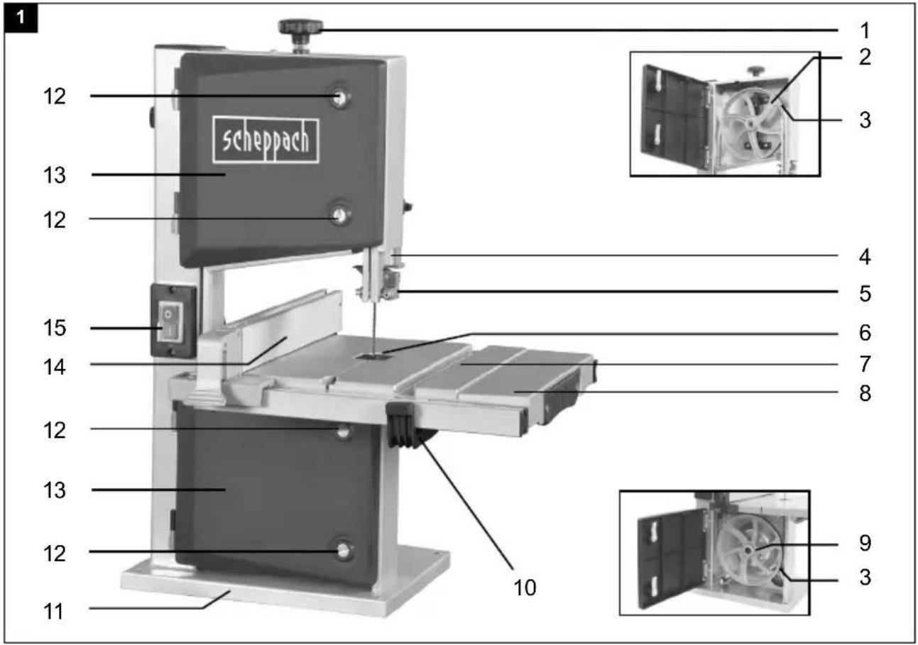
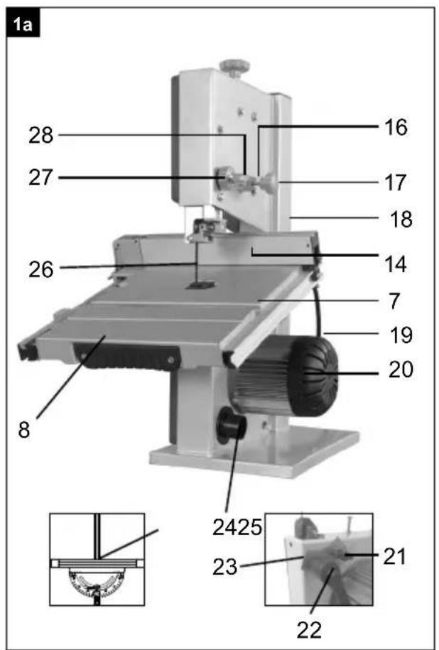
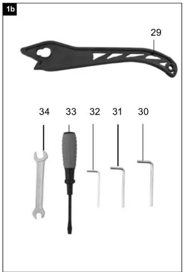
2. Device description (Fig. 1-1b)
- Clamping screw
- Top saw band roller
- Rubber surface
- Saw band guard
- Top saw band guide
- Table insert
- Saw table
- Table enlargement
- Bottom saw band roller
- Clamping lever
- Foot
- Cover locking mechanism
- Side cover
- Parallel stop
- On/off switch
- Locking screw for top saw band roller
- Set screw for top saw band roller
- Machine frame
- Mains cable
- Motor
- Wing nut
- Locking handle for saw table
- Clamping plate
- Extraction nozzle
- Mitre gauge (optional)
- Saw band
- Adjustment handle for saw band guide
- Locking handle for saw band guide
- Push stick
- Allen key 5mm
- Allen key 4mm
- Allen key 3mm
- Screwdriver
- Open-ended spanner SW10/13
- Degree scale for swivel range
-
Screw M6x35
-
Flat washer M6
- Nut M6
- Screw M5x7
- Serrated washer M5
- Knurled nut for parallel stop
- Clamping lever for parallel stop
- Guide rail for parallel stop
- Inspection glass
- Allen screw for top support bearing
- Top support bearing
- Top guide pin
- Allen screw for top guide pins
- Retainer (top)
- Allen screw top retainer (2x)
- Allen screw bottom support bearing
- Bottom support bearing
- Screw bottom retainer
- Saw band protection
- Allen screw for bottom guide pins
- Bottom guide pin
- Retainer (bottom)
- Screw (saw table adjustment)
- Nut (saw table adjustment)
- Push Stick retainer
3. Scope of delivery
- Open the packaging and remove the device carefully.
- Remove the packaging material as well as the packaging and transport bracing (if available).
- Check that the delivery is complete.
- Check the device and accessory parts for transport damage.
- If possible, store the packaging until the warranty period has expired.
⚠ ATTENTION! The device and packaging materials are not toys! Children must not be allowed to play with plastic bags, film and small parts! There is a risk of swallowing and suffocation!
1x Band saw
1x Saw table (7)
1x Table extension (8) with guide rail (43)
1x Parallel stop (14)
1x Push stick (29)
1x Open-end spanner, size 10/13 (34)
3x Allen key 3mm (32)/4mm(31)/5mm (30)
1x Screw M6x35 (36)
1x Flat washer M6 (37)
1x Nut M6 (38)
2x Screw M5x7 (39)
2x Serrated washer M5 (40)
1x Original operating manual
Optional:
1x Cross cutting gauge (25)
1x Saw band (6 teeth/inch)
1x Saw band (10 teeth/inch)
1x Saw band (15 teeth/inch)
4. Intended use
The band saw is designed to perform longitudinal and cross cuts on timber or wood-type materials. To cut round materials you must use suitable holding devices.
The equipment is to be used only for its prescribed purpose. Any other use is deemed to be a case of misuse. The user / operator and not the manufacturer will be liable for any damage or injuries of any kind caused as a result of this.
The machine is to be operated only with suitable saw blades. To use the machine properly you must also serve the safety regulations, the assembly instructions and the operating instructions to be found in this manual.
All persons who use and service the machine have to be acquainted with this manual and must be informed about the machine's potential hazards. It is also imperative to observe the accident prevention regulations in force in your area. The same applies for the general rules of occupational health and safety.
The manufacturer shall not be liable for any changes made to the machine nor for any damage resulting from such changes.
Even when the machine is used as prescribed it is still impossible to eliminate certain residual risk factors. The following hazards may arise in connection with the machine's construction and design:
Please note that our equipment has not been designed for use in commercial, trade or industrial applications. Our warranty will be voided if the equipment is used in commercial, trade or industrial businesses or for equivalent purposes.
General safety information for electric tools
⚠ WARNING: Read all safety warnings, instructions, illustrations and specifications provided with this power tool.
Failure to follow all instructions listed below may result in electric shock, fire and/or serious injury.
Save all warnings and instructions for future reference.
The term "power tool" in the warnings refers to your mains-operated (corded) power tool or battery-operated (cordless) power tool.
1) Work area safety
a) Keep your work area clean and well-lit. Cluttered or dark areas invite accidents.
b) Do not operate power tools in explosive atmospheres, such as in the presence of flammable liquids, gases or dust. Power tools create sparks which may ignite the dust or fumes.
c) Keep children and bystanders away while operating a power tool. Distractions can cause you to lose control.
2) Electrical safety
a) Power tool plugs must match the outlet. Never modify the plug in any way. Do not use any adapter plugs with earthed (grounded) power tools. Unmodified plugs and matching outlets will reduce risk of electric shock.
b) Avoid body contact with earthed or grounded surfaces, such as pipes, radiators, ranges and refrigerators. There is an increased risk of electric shock if your body is earthed or grounded.
c) Do not expose power tools to rain or wet conditions. Water entering a power tool will increase the risk of electric shock.
d) Do not abuse the cord. Never use the cord for carrying, pulling or unplugging the power tool. Keep cord away from heat, oil, sharp edges or moving parts. Damaged or entangled cords increase the risk of electric shock.
e) When operating a power tool outdoors, use an extension cord suitable for outdoor use. Use of a cord suitable for outdoor use reduces the risk of electric shock.
f) If operating a power tool in a damp location is unavoidable, use a residual current device (RCD) protected supply. Use of an RCD reduces the risk of electric shock.
3) Personal safety
a) Stay alert, watch what you are doing and use common sense when operating a power tool. Do not use a power tool while you are tired or under the influence of drugs, alcohol or medication. A moment of inattention while operating power tools may result in serious personal injury.
b) Wear personal protective equipment and always safety goggles. Protective equipment such as a dust mask, non-skid safety shoes, safety helmet or hearing protection used for appropriate conditions will reduce personal injuries.
c) Prevent unintentional starting. Ensure the switch is in the off-position before connecting to power source and/or rechargeable battery, picking up or carrying the tool. Carrying power tools with your finger on the switch or energising power tools that have the switch on invites accidents.
d) Remove any adjusting tools or spanners/keys before turning the power tool on. A wrench or a key left attached to a rotating part of the power tool may result in personal injury.
e) Avoid abnormal postures. Keep proper footing and balance at all times. This enables better control of the power tool in unexpected situations.
f) Wear suitable clothing. Do not wear loose clothing or jewellery. Keep your hair and clothing away from moving parts. Loose clothes, jewellery or long hair can be caught in moving parts.
g) If devices are provided for the connection of dust extraction and collection facilities, ensure these are connected and properly used. Use of dust extraction can reduce dust-related hazards.
h) Do not let familiarity gained from frequent use of tools allow you to become complacent and ig-
nore tool safety principles. A careless action can cause severe injury within a fraction of a second.
4) Power tool use and care
a) Do not force the power tool. Use the correct power tool for your application. The correct power tool will do the job better and safer at the rate for which it was designed.
b) Do not use the power tool if the switch does not turn it on and off. Any power tool that cannot be controlled with the switch is dangerous and must be repaired.
c) Disconnect the plug from the power source and/or remove the battery pack, if detachable, from the power tool before making any adjustments, changing accessories, or storing power tools. Such precautionary measures reduce the risk of starting the power tool accidentally.
d) Store idle power tools out of the reach of children and do not allow persons unfamiliar with the power tool or these instructions to operate the power tool. Power tools are dangerous in the hands of untrained users.
e) Maintain power tools and attachments. Check for misalignment or binding of moving parts, breakage of parts and any other condition that may affect the power tool's operation. If damaged, have the power tool repaired before use. Many accidents are caused by poorly maintained power tools.
f) Keep cutting tools sharp and clean. Properly maintained cutting tools with sharp cutting edges are less likely to bind and are easier to control.
g) Use the power tool, accessories and tool bits etc. in accordance with these instructions. Take into account the working conditions and the work to be performed. Use of the power tool for operations different from those intended could result in a hazardous situation.
h) Keep handles and grasping surfaces dry, clean and free from oil and grease. Slippery handles and grasping surfaces do not allow for safe handling and control of the tool in unexpected situations.
5) Service
a) Have your power tool serviced by a qualified repair person using only identical replacement parts. This will ensure that the safety of the power tool is maintained.
Additional safety instructions
- Wear safety gloves whenever you carry out any maintenance work on the blade!
- When cutting round or irregularly shaped wood, use a device to stop the workpiece from twisting.
- When cutting boards in upright position, use a device to prevent kick-back.
- A dust extraction system designed for an air velocity of 20 m/s should be connected in order to comply with woodworking dust emission values and to ensure reliable operation.
- Give these safety regulations to all persons who work on the machine.
- Do not use this saw to cut fire wood.
- The machine is equipped with a safety switch to prevent it being switched on again accidentally after a power failure.
- Before you use the machine for the first time, check that the voltage marked on the rating plate is the same as your mains voltage.
- If you use a cable reel, the complete cable has to be pulled off the reel.
- Persons working on the machine should not be distracted.
- Note the direction of rotation of the motor and blade.
- Never dismantle the machine's safety devices or put them out of operation.
- Never cut workpieces which are too small to hold securely in your hand.
- Never remove loose splinters, chips or jammed pieces of wood when the saw blade is running.
- It is imperative to observe the accident prevention regulations in force in your area as well as all other generally recognized rules of safety.
• Note the information published by your professional associations.
- Adjustable protective devices have to be adjusted as close as possible to the work piece.
⚠ IMPORTANT! Support long work pieces (e.g. with a roller table) to prevent them sagging at the end of a cut.
• Make sure the blade guard (4) is in its lower position when the saw is being transported.
- Safety guards are not to be used to move or misuse the machine.
- Blades that are misshapen or damaged in any way must not be used.
- If the table insert is worn, replace it.
- Never operate the machine if either the door protecting the blade or the detachable safety device are open.
- Ensure that the choice of blade and the selected speed are suitable for the material to be cut.
- Do not begin cleaning the blade until it has come to a complete standstill.
- For straight cuts of small work pieces against the longitudinal limit stop the push stick has to be used.
- Wear gloves when handling the saw blade and rough materials
- The band saw blade guard should be in its lowest position close to the bench during transport.
- For miter cuts when the table is tilted, the parallel stop must be positioned on the lower part of the table.
- Never use guards to lift or transport items.
- Ensure that the band saw blade guards are used and correctly adjusted.
- Keep your hands a safety distance away from the band saw blade. Use a push stick for narrow cuts.
- The push stick has to be stored on the intended device, so that it can be reached from normal working position and is always ready to be used.
- In the normal operating position the operator is in front of the machine.
⚠ WARNING! This electric tool generates an electromagnetic field during operation. This field can impair active or passive medical implants under certain conditions. In order to prevent the risk of serious or deadly injuries, we recommend that persons with medical implants consult with their physician and the manufacturer of the medical implant prior to operating the electric tool.
Remaining hazards
The machine has been built using modern technology in accordance with recognized safety rules. Some remaining hazards, however, may still exist.
- Risk of injury for fingers and hands by the rotating saw band due to improper handling of the work piece. Risk of injury through the hurling work piece due to improper handling, such as working without the push stick.
- Risk of damaging your health due to wood dust and wood chips. Wear personal protective cloth such as goggles. Use a fitting dust extractor.
- Risk of injury due to defective saw band. Regularly check saw band for such defects.
- Risk of injury for fingers and hands while changing saw band. Wear proper gloves.
- Risk of injury due to starting saw band while switching on the machine.
- The use of incorrect or damaged mains cables can lead to injuries caused by electricity.
-
Wear only close fitting clothes. Remove rings, bracelets and other jewelry.
-
For the safety of long hair, wear a cap or hair net. Even when all safety measures are taken, some remaining hazards which are not yet evident may still be present.
- Remaining hazards can be minimized by following the instructions in „General safety instructions“ „Proper Use“ and in the entire operating manual.
6. Technical data
Electro motor 230 - 240 V \~ 50 Hz
| Power | S1* 250WS2** 30 min 350W |
| Revolutions n_0 | 1400 rpm |
| Saw band length 1400 mm | |
| Saw band width 6-12 mm | |
| Cutting speed 900 m/min | |
| Passage height 0 - 80 mm | |
| Passage width 200 mm | |
| Table size 300 x 300 mm | |
| Table size with min.extension | 380 x 300 mm |
| Table size with max.extension | 535 x 300 mm |
| Slewing range of the table 0° - 45° | |
| Max. size of the workpiece 400 x 400 x 80 mm | |
| Overall weight | 19 kg |
Subject to technical modifications!
* Operating mode S1, continuous operation
** Operating mode S2, short-term operation with constant load; Duration of nominal operation
The work piece must have a minimum height of 3 mm and a minimum width of 10 mm.
The total noise values determined in accordance with EN 62841.
| Sound pressure level L_pA | 77.4 dB |
| Uncertainty K_pA | 3 dB |
| Sound power level L_WA | 90.4 dB |
| Uncertainty K_WA | 3 dB |
Wear hearing protection!
The effects of noise can cause a loss of hearing. Total vibration emission values (vector sum of three directions) determined per EN 62841.
7. Before starting the equipment
Make sure the machine stands securely, i.e. bolt it to a workbench or solid base. There are two holes for this purpose in the machine foot.
- The saw table must be mounted correctly.
- All covers and safety devices have to be properly fitted before the machine is switched on.
- It must be possible for the blade to run freely.
- When working with wood that has been processed before, watch out for foreign bodies such as nails or screws etc.
- Before you actuate the On/Off switch, make sure that the saw blade is correctly fitted and that the machine's moving parts run smoothly.
- Before you connect the machine to the power supply, make sure the data on the rating plate is the same as that for your mains.
8. Attachment
ATTENTION! Before all maintenance, set-up and assembly work on the band saw, unplug the mains plug.
1 Open-ended spanner, size 10/13
1 Allen key, size 3
1 Allen key, size 4
1 Screwdriver
The saw table and table extension are not assembled for packaging reasons.
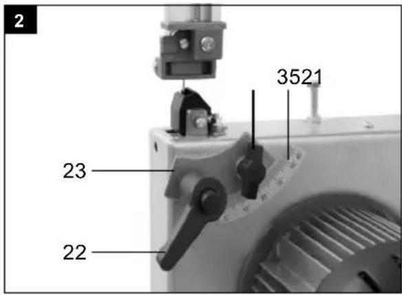
8.1 Assembling the saw table (Fig. 2-3)
- Remove the wing nut (21), the locking handle (22), the two washers and the clamping plate (23). (Fig. 2)
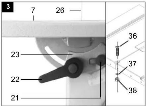
- Guide the saw table (7) over the Bandsaw blade (26). Fasten it to the two screws on the machine frame with the plate (23), the two washers, the wing nut (21) and the locking handle (22). (Fig. 3)
- Fit the bolt M6x35 (36) with two washers (37) and the nut (38) to the table. (Fig. 3)
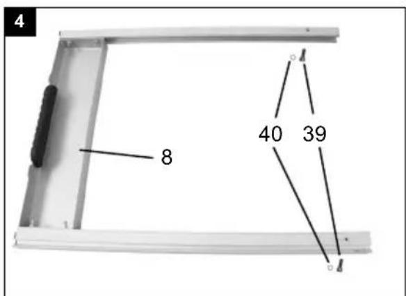
8.2 Fitting the table width enlargement
(Fig. 4 + 4.1 + 4.2 + 4.3 + 4.4)
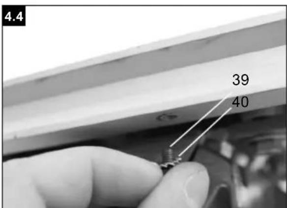
- Remove the two bolts (39) and washers (40) from the table width enlargement (8). (Fig. 4)
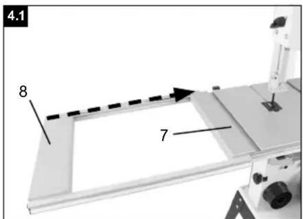
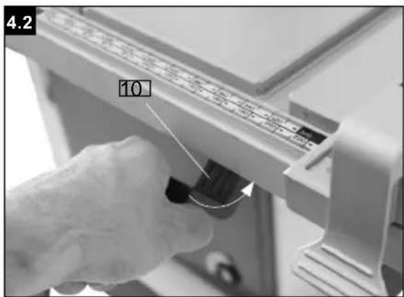
- Slide the table width enlargement (8) onto the table (7) mounted on the machine. Ensure that the clamping lever (10) is open (Fig. 4.1+4.2).
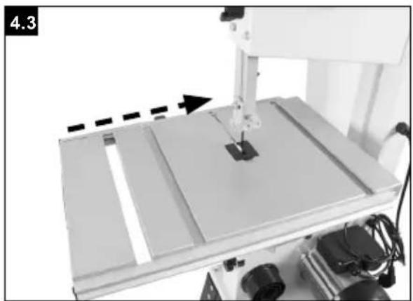
- Push the table width enlargement fully onto the table (Fig. 4.3) in order to fix the two bolts (39) on both sides. (Fig. 4.4) Be sure to fit the bolts (39) on both sides. The two bolts are used to limit the extension of the table width enlargement.
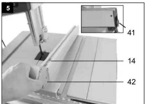
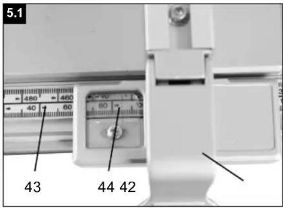
8.3 Fitting the parallel stop (Fig. 5)
- Fit the parallel stop (14) by positioning it at the back and fixing the clamping lever (42) in place downwards.
- When dismantling, pull the clamping lever (42) upwards and remove the parallel stop (14).
- The clamping force of the parallel stop can be adjusted at the rear knurled nut (41).
8.4 Adjusting the cutting width (Fig. 5 + 5.1)
- The parallel stop (14) must be used when cutting sections of wood lengthways.
- Place the parallel stop (14) on the guide rail (43) to the left or right of the sawing blade
- 2 scales are printed on the guide rail for the parallel stop (43), which show the distance between the stop rail and sawing blade.
- Adjust the parallel stop (14) to the required dimension in the window (44) and use the clamping lever (42) to fix in place for the parallel stop. (Fig. 5)
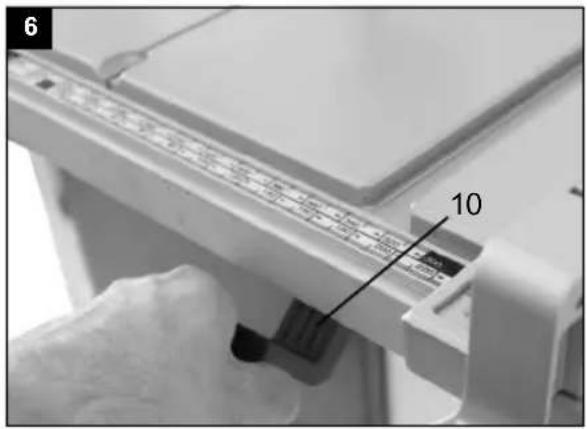
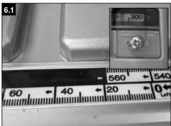
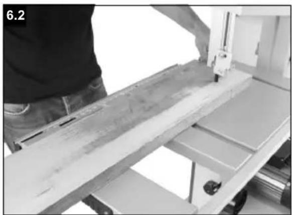
8.5 Using the table width enlargement (Fig. 6-6.2)
• Always use the table width enlargement (8) with particularly wide workpieces.
- Loosen the clamping lever (10) and pull the table width enlargement out far enough so that the workpiece to be sawn can lie on it without tipping. (Fig. 6.2)
8.6 Tensioning the saw band (Fig. 1)
△ ATTENTION! If the saw is at a standstill for an extended period the saw band tension must be relieved, i.e. before switching the saw on it is necessary to check the saw blade tension.
- Turn the clamping screw (1) clockwise to tension the Bandsaw blade (26). The correct tension of the saw band can be determined by pressing the finger laterally against the saw band, roughly centrally between the two saw band rollers (2+9). The Bandsaw blade (26) should only depress slightly (approx. 1-2 mm) here.
- The sufficiently tensioned saw band makes a metallic sound when tapped.
- Relieve the saw band tension if it is not in use for an extended time, so that it does not become over-stretched.
ATTENTION! With high tension, the saw band may break. RISK OF INJURY! If the tension is too low, the driven saw band roller (8) may spin, resulting in the saw band coming to a standstill.
8.7 Adjusting the saw band (Fig. 1 + 1a)
⚠ ATTENTION! Before it is possible to implement the saw band setting, the saw band must be tensioned correctly.
- Open the side covers (13) by undoing the cover locking mechanisms (12) with the help of the screwdriver (33).
- Slowly turn the saw band roller (2) clockwise. The Bandsaw blade (26) should run centrally on the saw band roller (2). If this is not the case, the angle of the top saw band roller (2) must be corrected.
- If the Bandsaw blade (26) runs more towards the rear edge of the saw band roller (2) then the set screw (17) must be rotated anticlockwise.
- Open the locking screw for the top saw band roller (16).
- Turn the bottom saw band roller (9) slowly by hand, to check the position of the Bandsaw blade (26).
- If the Bandsaw blade (26) runs more towards the front edge of the saw band roller (2) then the set screw (17) must be rotated clockwise.
- After setting the top saw band roller (2), check the position of the Bandsaw blade (26) on the bottom saw band roller (9). The Bandsaw blade (26) should also lie centrally on the saw band roller (9) here. If this is not the case, the angle of the top saw band roller (2) must be adjusted again.
- Turn the saw band roller a few times, until the adjustment of the top saw band roller (2) acts on the saw band position on the bottom saw band roller (9).
- Tighten the locking screw for the top saw band roller (16).
- Once adjustment is complete, close the side covers (13) again and secure with the cover locking mechanisms (12) with the help of the screwdriver (33).
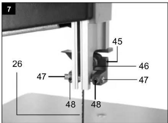
8.8 Adjusting the saw band guide (Fig. 7-10)
Both the support bearing (46 + 52) and the guide pins (47
+ 56) must be readjusted after every saw band change.
- Open the side covers (13) by undoing the cover locking mechanisms (12) with the help of the screwdriver (33).
8.8.1 Top support bearing (46) (Fig. 7)
- Undo Allen screw for top support bearing (45).
- Move support bearing (46) sufficiently far that it just no longer touches the Bandsaw blade (26) (distance max. 0.5 mm).
- Retighten the Allen screw for the top support bearing (45).
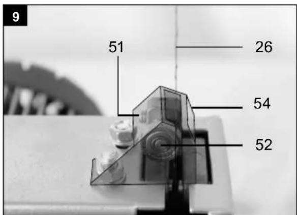
8.8.2 Adjusting the bottom support bearing (52) (Fig. 9)
- Disassemble the saw table as per 8.1 in the opposite direction.
- Undo Allen screw for bottom support bearing (51).
- Move bottom support bearing (52) sufficiently far that it just no longer touches the Bandsaw blade (26) (distance max. 0.5 mm).
- Retighten Allen screw for bottom support bearing (51).
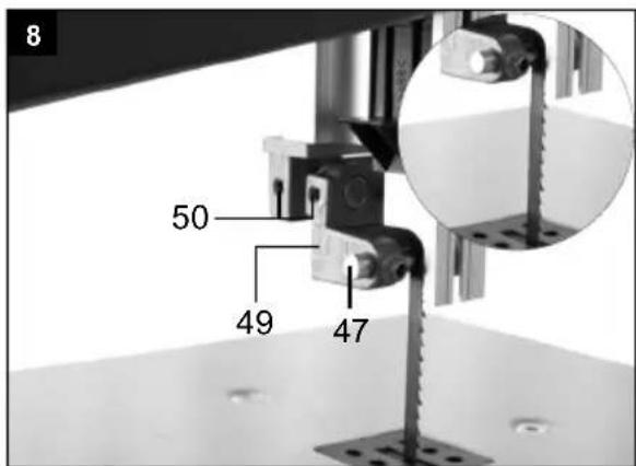
8.8.3 Adjusting the top guide pins (47) (Fig. 7 + 8)
- Undo Allen screws for top retainer (50)
- Move top retainer (49), top guide pins (47), until the front edge of the guide pins (47) is approx. 1 mm behind the tooth base of the saw band.
• Retighten Allen screws for top retainer (50).
⚠ ATTENTION! The saw band will be unusable if the teeth touch the guide pins with the saw band running.
- Undo Allen screws for top guide pins (48).
- Slide the guide pins (47) in the direction of the saw band!
△ ATTENTION! The distance between the guide pins (47) and Bandsaw blade (26) must not exceed 0.5 mm. (Saw band must not jam)
• Retighten Allen screws (48).
- Turn the top saw band roller (2) a few times in a clockwise direction.
- Check the setting of the top guide pins (47) again and adjust if necessary.
- If necessary, adjust the top support bearing (46) (8.8.1).
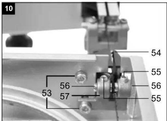
8.8.4 Adjusting the bottom guide pins (56) (Fig. 9+10)
• Disassemble saw table (7)
- Undo screw for bottom retainer (53) (Allen key, size 5)
- Move bottom retainer (57), bottom guide pins (56), until the front edge of the bottom guide pins (56) is approx. 1 mm behind the tooth base of the saw band.
• Retighten screw for bottom retainer (53).
⚠️ ATTENTION! The saw band will be unusable if the teeth touch the guide pins with the saw band running.
- Undo Allen screws for bottom guide pins (55).
-
Slide the two bottom guide pins (56) sufficiently far in the direction of the saw band that the distance between the guide pins (56) and Bandsaw blade (26) is max. 0.5 mm. (Saw band must not jam)
-
Retighten Allen screws for bottom guide pins (55).
- Turn the bottom saw band roller (9) a few times in a clockwise direction.
- Check the setting of the bottom guide pins (56) again and adjust if necessary.
- If necessary, adjust the bottom support bearing (52) (8.8.2).
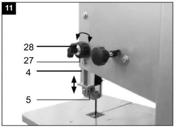
8.9 Adjusting the top saw band guide (5) (Fig. 11)
- Undo locking handle for saw band guide (28).
- Turn the adjustment handle for the saw band guide (27) to lower the saw band guide (5) as closely as possible (distance approx. 2-3 mm) over the material to be cut.
• Retighten locking handle (28).
- Check the setting before every cutting process and adjust if necessary.
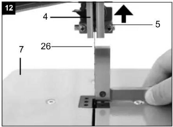
8.10 Adjusting the saw table (7) to 90° (Fig. 2+12+13)
- Set the top saw blade guide (5) fully upwards. (8.9)
- Undo locking handle (22) and wing nut (21) (Fig. 2).
- Place the angle bracket between the Bandsaw blade (26) and saw table (7). Angle bracket not included in the scope of supply.
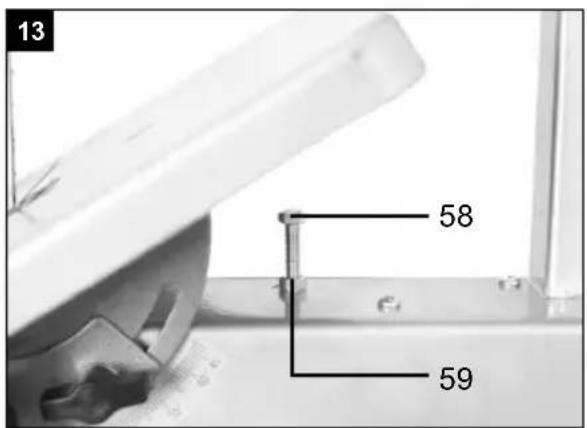
- Tilt the saw table (7) by turning, until the angle to the Bandsaw blade (26) is precisely 90°. If the saw table is already on the screw (58) and a 90° angle cannot be set, undo the nut (59) and shorten the screw (58) by turning in a clockwise direction.
- Retighten the locking handle (22) and wing nut (21).
• Also undo the nut (59).
- Adjust the screw (58) sufficiently that the saw table touches the underside.
- Retighten the nut (58) to fix the screw (59) in position.
8.11 Which saw band to use
The saw band supplied in the band saw is intended for universal use. The following criteria should be considered when selecting the saw band:
- It is possible to cut tighter radii with a narrow saw band than with a wide saw band.
- A wide saw band is used if a straight cut is required. This is important in particular when cutting wood. The saw band has a tendency to follow the wood grain and therefore deviates easily from the desired cutting line.
- Fine-toothed saw bands cut more smoothly, but also more slowly than coarse saw bands.
⚠️ ATTENTION! Never use bent or torn saw bands!
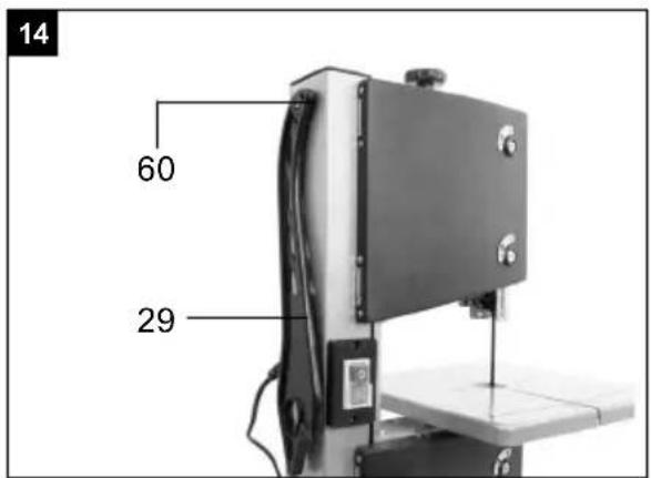
8.12 Push Stick retainer (Fig. 14)
The Push Stick retainer (60) is pre-mounted on the machine frame. If unused, the Push stick (29) must always be stowed in the Push Stick retainer.
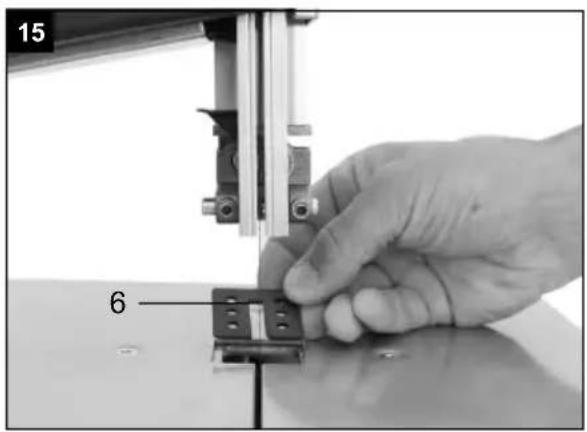
8.13 Replacing the table insert (Fig. 15)
In case of wear or damage, the table insert (6) must be replaced; otherwise there is an increased risk of injury.
- Remove the worn table insert (6) by lifting it up and out.
- Installation of the new table insert takes place in reverse order.
8.14 Replacing the saw band (Fig. 1a+1b+14)
- Set the saw band guide (5) at approx. half height between the saw table (7) and machine frame (18).
- Undo the cover locking mechanisms (12) and open the side covers (13).
- Remove the screw M6x35 (36) with two washers (37) and the nut (38) of the table. (Fig. 3)
- Relieve the Bandsaw blade (26) tension by turning the clamping screw (1) anti-clockwise.
- Remove the Bandsaw blade (26) from the saw band rollers (2+9) and through the slot in the saw table (7).
- Place the new Bandsaw blade (26) centrally on both saw band rollers (2+9). The teeth of the Bandsaw blade (26) must point downwards in the direction of the saw table (Fig. 6).
• Tension the Bandsaw blade (26) (see 8.6)
- Close the side cover (13) again.
- Mount the M6x35 bolt (36) to the table with two washers (37) and the nut (38). (Fig. 3)
The band saw is equipped with an extraction nozzle (24) ∅ 40 mm for chips.
Only operate the device with a suitable extraction system. Check and clean the suction channels at regular intervals.
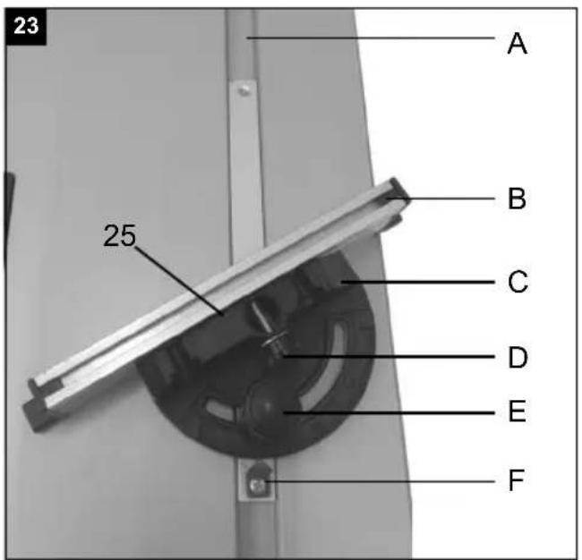
8.16 Mitre gauge (optional) (25) (Fig. 23)
- Slide lateral stop (25) into a groove (A) in the saw bench.
- Release the grip screw (E).
- Turn the lateral stop (C) until the desired angular dimension has been set. The arrow (F) on the lateral stop indicates the set angle.
• Retighten the grip screw (E).
- The stop rail (B) can be slid against the lateral stop (C). To do so, loosen the knurled screws (D) and slide the stop rail (B) into the desired position. Tighten the knurled screws (D) again
⚠ ATTENTION! Do not slide the stop rail (B) too far in the direction of the saw blade.
△ ATTENTION! When working with the machine, all protective devices and guards must be fitted.
The upper and lower bandwheel is protected by a fixed guard and an articulated cover. When opening the cover, the machine is switched off. Starting is possible only with closed cover.
9. Operation
ATTENTION!
Always make sure the product is fully assembled before commissioning!
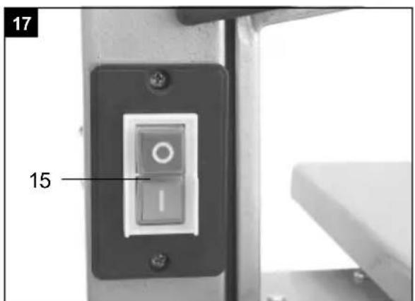
9.1 On/Off switch (15) (Fig. 17)
- To turn the machine on, press the green button „I“.
- To turn the machine off again, press the red button „0“.
- The band saw is equipped with an under voltage switch. With a power failure, the band saw must be switched back on again.
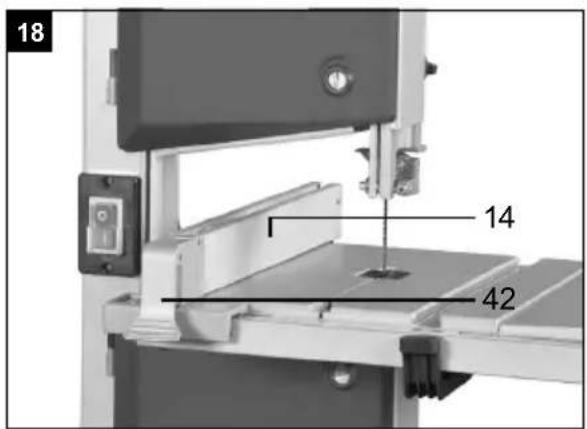
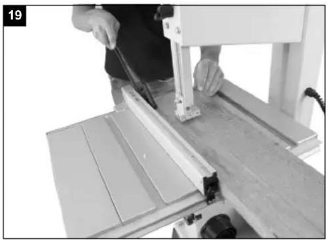
9.2 Fitting the parallel stop (Fig. 5+18)
- Place the parallel stop (14) on the guide rail (43) to the left or right of the sawing blade.
- Press the clamping bar (42) down to fix the parallel stop (14) in place. The clamping force of the parallel stop can be adjusted at the rear knurled nut (41).
- Make sure that the parallel stop (14) always runs parallel to the band saw blade (26).
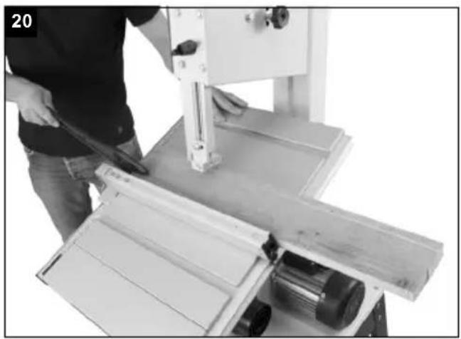
9.3 Angled cuts (Fig. 20)
In order to execute angled cuts parallel to the band saw blade (26), it is possible to tilt the saw bench (7) forwards from 0^ - 45^ .
- Undo locking handle (22) and wing nut (21).
- Tilt saw bench (7) forwards, until the desired angle is set on the degree scale (35).
- Retighten the locking handle (22) and wing nut (21).
△ ATTENTION! With a tilted saw table (7), the parallel stop (14) must always be fitted to the right of the band saw blade (26) in the working direction. This prevents the workpiece from slipping.
10. Working instructions
The following recommendations are examples of the safe use of band saws.
The following safe working methods should be seen as an aid to safety. They cannot be applied suitably completely or comprehensively to every use. They cannot treat every possible dangerous condition and must be interpreted carefully.
- Connect the machine to a suction unit when working in closed rooms. A suction device which conforms with commercial regulations must be used for suction in commercial areas.
- Loosen the sawband when the machine is not in operation (e.g. after finishing work). Attach a notice on the tension of the saw band to the machine for the next user.
- Collect unused sawbands and store them safely in a dry place. Check for faults (teeth, cracks) before use. Do not use faulty sawbands!
- Wear suitable gloves when handling sawbands.
- All protective and safety devices must be securely mounted on the machine before beginning work.
- Never clean the sawband or the sawband guide with a hand-held brush or scraper while the sawband is running. Resin-covered sawbands impair working safety and must be cleaned regularly.
- For your own protection, wear protective glasses and hearing protection. Wear a hairnet if you have long hair. Roll up loose sleeves over the elbows.
- Always position the sawband guide as near the workpiece as possible when working.
- Insure sufficient lighting in the work area and around the machine.
• Always use the fence for straight cuts to keep the workpiece from tipping or slipping away.
- When working on narrow workpieces with manual feed, use the push stick.
- For diagonal cuts, place the saw bench in the appropriate position and guide the workpiece on the fence.
- In order to cut dovetail tenons and teeth or wedges, bring the saw table into the corresponding position on the angle scale.
- For arced and irregular cuts, push the workpiece evenly using both hands with the fingers together. Hold the workpiece with your hands on a safe area.
- Use a pattern for repeated arced or irregular cuts.
- Insure that the workpiece does not roll when cutting round pieces.
⚠ ATTENTION! After every new setting, we recommend performing a test cut, in order to check the dimensional settings.
- With all cutting processes, the top saw band guide (5) must be positioned as close as possible to the workpiece (see 8.9).
- The workpiece must always be guided with both hands and kept flat against the saw table (7). This prevents the Bandsaw blade (26) from jamming.
- Forward feeding should always take place with an even pressure, which is just sufficient for the saw band to cut through the material with ease without becoming blocked.
• Always use the parallel stop (14) for all cutting processes that it can be used for.
- It is better to perform a cut in a single working step than in multiple steps, which may require that the workpiece be drawn back. However, if it is not possible to avoid drawing the workpiece back then the band saw must be switched off first. Only draw the workpiece back once the Bandsaw blade (26) has come to a standstill.
- When sawing, the workpiece must always be guided by its longest side.
⚠️ ATTENTION! When processing narrower workpieces it is essential to use a Push stick. The Push stick (29) must always be stored within reach, on the Push Stick retainer (60) provided for this purpose on the side of the saw.
Here, a workpiece is cut in its longitudinal direction.
- Position the longitudinal fence (14) on the left side (if possible) of the Bandsaw blade (26), in accordance with the desired width.
- Lower the saw band guide (5) onto the workpiece (8.9).
- Switch on the saw (see 9.1).
- Press one edge of the workpiece against the longitudinal fence (14) with the right hand, whilst the flat side lies on the saw bench (7).
- Slide the workpiece at an even feed rate along the longitudinal fence (14) into the Bandsaw blade (26).
- Important: Long workpieces must be secured against tipping at the end of the cutting process (e.g. with reel-off stand, etc.)
- Set saw bench to desired angle (see 9.3).
• Perform the cut as described under 10.1.
When producing angled cuts, only use the parallel stop to the right of the saw band.
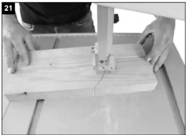
10.3 Freehand cuts (Fig. 21)
• One of the most important features of a band saw is the ease with which it can cut curves and radii.
- Lower the saw band guide (5) onto the workpiece (see 8.9).
- Switch on the saw.
- Press the workpiece firmly onto the saw bench (7) and slowly slide into the Bandsaw blade (26).
- In many cases it is helpful to roughly saw curves and corners approximately 6 mm from the line.
- If it is necessary to saw curves that are too tight for the saw band used, auxiliary cuts must be sawn up to the front face of the curve, so that these fall off as wood waste when the final radius is sawn.
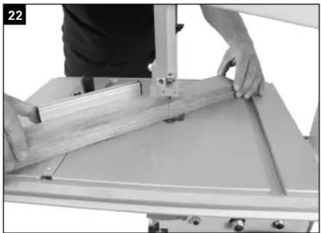
10.4 Executing cuts with the transverse cutting gauge (Fig. 22 + Fig. 23)
- Set transverse cutting gauge (25) to the desired angle (see 8.16)
• Perform the cut as described under 10.1.
11. Electrical connection
The electrical motor installed is connected and ready for operation. The connection complies with the applicable VDE and DIN provisions.
The customer's mains connection as well as the extension cable used must also comply with these regulations.
In the event of an overloading the motor will switch itself off. After a cool-down period (time varies) the motor can be switched back on again.
Damaged electrical connection cable
The insulation on electrical connection cables is often damaged.
This may have the following causes:
• Passage points, where connection cables are passed through windows or doors.
- Kinks where the connection cable has been improperly fastened or routed.
- Places where the connection cables have been cut due to being driven over.
• Insulation damage due to being ripped out of the wall outlet.
• Cracks due to the insulation ageing.
Such damaged electrical connection cables must not be used and are life-threatening due to the insulation damage.
Check the electrical connection cables for damage regularly. Make sure that the connection cable does not hang on the power network during the inspection.
Electrical connection cables must comply with the applicable VDE and DIN provisions. Only use connection cables with the marking „H05VV-F“.
The printing of the type designation on the connection cable is mandatory.
AC motor
- The mains voltage must be 220 - 240 V\~ 50 Hz.
- Extension cables up to 25 m long must have a cross-section of 1.5 ~mm^2 .
Connections and repairs of electrical equipment may only be carried out by an electrician.
Please provide the following information in the event of any enquiries:
• Type of current for the motor
• Machine data - type plate
• Machine data - type plate
Connection type Y
If it is necessary to replace the mains connection cable, this must be done by the manufacturer or their representative to avoid safety hazards.
12. Cleaning, maintenance and storage
⚠️ IMPORTANT!
Prior to any adjustment, maintenance or service work disconnect the mains power plug!
Cleaning
Keep all safety devices, air vents and the motor housing free of dirt and dust as far as possible. Wipe the equipment with a clean cloth or blow it with compressed air at low pressure.
We recommend that you clean the device immediately each time you have finished using it.
Maintenance
There are no parts inside the equipment which require additional maintenance.
Storage
Store the device and its accessories in a dark, dry and frost-proof place that is inaccessible to children. The optimum storage temperature is between 5 and 30°C. Store the power tool in original packaging.
Cover the electrical tool in order to protect it from dust and moisture.
Store the operating manual with the electrical tool.
Please note that the following parts of this product are subject to normal or natural wear and that the following parts are therefore also required for use as consumables.
Wear parts*: Carbon brushes, saw blade, table inlays; v-belt
* Not necessarily included in the scope of delivery!
Spare parts and accessories can be obtained from our service centre. To do this, scan the QR code on the cover page.
13. Transport
The machine must only be lifted and transported on its frame or the frame plate. Never lift the machine at the safety devices, the adjusting levers, or the sawing table.
During the transport the saw blade protection must be in the lowest position and near the table.
Never raise at the table! Unplug the machine from the mains during transport.
14. Disposal and recycling
Notes for packaging


The packaging materials are recyclable. Please dispose of packaging in an environmentally friendly manner.
Notes on the electrical and electronic equipment act [ElektroG]
![SCHEPPACH HBS30 - Notes on the electrical and electronic equipment act [ElektroG] - 1](/content/2026/03/573052/images/51cf5ecfb6c7bf11bafe4df50723e49d9b144bbdfa2bcd0f0969689a43f2bbb0.jpg)
Waste electrical and electronic equipment does not belong in household waste, but must be collected and disposed of separately!
- Used batteries or rechargeable batteries that are not installed permanently in the old appliance must be removed non-destructively before disposal. Their disposal is regulated by the battery law.
- Owners or users of electrical and electronic devices are legally obliged to return them after use.
- The end user is responsible for deleting their personal data from the old device being disposed of!
- The symbol of the crossed-out dustbin means that waste electrical and electronic equipment must not be disposed of with household waste.
-
Waste electrical and electronic equipment can be handed in free of charge at the following places: - Public disposal or collection points (e.g. municipal works yards)
-
Points of sale of electrical appliances (stationary and online), provided that dealers are obliged to take them back or offer to do so voluntarily.
- Up to three waste electrical devices per type of device, with an edge length of no more than 25 centimetres, can be returned free of charge to the manufacturer without prior purchase of a new device from the manufacturer or taken to another authorised collection point in your vicinity.
- Further supplementary take-back conditions of the manufacturers and distributors can be obtained from the respective customer service.
- If the manufacturer delivers a new electrical appliance to a private household, the manufacturer can arrange for the free collection of the old electrical appliance upon request from the end user. Please contact the manufacturer's customer service for this.
- These statements only apply to devices installed and sold in the countries of the European Union and which are subject to the European Directive 2012/19/EU. In countries outside the European Union, different regulations may apply to the disposal of waste electrical and electronic equipment.
15. Troubleshooting
| Fault Possible cause Remedy |
| Motor does not work Motor, cable or plug defective, fuses burntHousing cover open (limit switch) | Arrange for inspection of the machine by a specialist. Never repair the motor yourself. Danger!Check fuses and replace if necessaryClose housing cover exactly | |
| The motor starts up slowly and does not reach operating speed. | Voltage too low, coils damaged, capacitor burnt | Contact the utility provider to check the voltage.Arrange for inspection of the motor by a specialist.Arrange for replacement of the capacitor by a specialist |
| Motor makes excessive noise | Coils damaged, motor defective Arrange for inspection of the motor by a specialist | |
| The motor does not reach its full power. | Circuits in the network are overloaded (lamps other motors, etc.) | Do not use any other equipment or motors on the same circuit |
| Motor overheats easily. Overloading of the motor, insufficient cooling of the motor | Avoid overloading the motor while cutting, remove dust from the motor in order to ensure optimal cooling of the motor | |
| Saw cut is rough or wavy Saw blade dull, tooth shape not appropriate for the material thickness | Resharpen saw blade and/or use suitable saw blade | |
| Workpiece pulls away and/or splinters | Excessive cutting pressure and/or saw blade not suitable for use | Insert suitable saw blade |
| Saw blade is not running straight | Guide has been wrongly setWrong saw blade | Set the saw blade guide according to the operating instructionsSelect a saw blade according to the operating instructions |
| Burn marks appear on the wood during the cutting work | Blunt saw bladeWrong saw blade | Change the saw bladeSelect a saw blade according to the operating instructions |
| Saw blade jams during cutting work | Blunt saw bladeDeposits on the saw bladeGuide has been set poorly | Change the saw bladeClean the saw bladeSet the saw blade guide according to the operating instructions |
Günzburger Straße 69
D-89335 Ichenhausen
Chers clients,
1 clé plate SW 10/13
Günzburger Straße 69
D-89335 Ichenhausen
Egregio cliente,
Günzburger Straße 69
D-89335 Ichenhausen
Geachte klant,
Günzburger Straße 69
D-89335 Ichenhausen
Estimado cliente:
Günzburger Straße 69
D-89335 Ichenhausen
Estimado cliente,
Günzburger Straße 69
D-89335 Ichenhausen
Vážený zákazníku,
Günzburger Straße 69
D-89335 Ichenhausen
Vážený zákazník,
Günzburger Straße 69
D-89335 Ichenhausen
Tisztelt vásárló!
Günzburger Straße 69
D-89335 Ichenhausen
Szanowny kliencie,
Günzburger Straße 69
D-89335 Ichenhausen
Poštovani kupci,
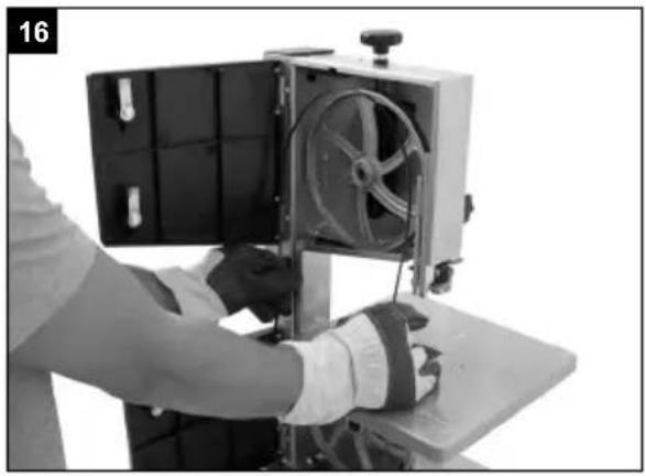
8.14 Zamjena trake pile (sl. 1a+1b+16)
- Namjestite vodilicu trake pile (5) otprilike na pola visine između stola za piljenje (7) i postolja stroja (18).
- Otpustite blokade poklopca (12) i otvorite bočni poklopac (13).
- Odvrnite vijak M6x35 (36) s dvije podložne pločice (37) i maticom (38) sa stola. (Sl. 3)
- Olabavite traku pile (26) okretanjem vijka za natezanje (1) nalijevo.
- Skinite traku pile (26) s kotura trake pile (2+9) i izvadite je kroz prorez u stolu za piljenje (7).
- Stavite novu traku pile (26) po sredini na oba kotura trake pile (2+9). Zubi trake pile (26) moraju biti usmjereni prema dolje u smjeru stola za piljenje (sl. 6).
• Nategnite traku pile (26) (vidi 8.6)
- Ponovno zatvorite bočni poklopac (13).
- Montirajte vijak M6x35 (36) s dvije podložne pločice (37) i maticom (38) na stol. (Sl. 3)
8.15 Usisni nastavak (sl. 1a)
Tračna pila opremljena je usisnim nastavkom (24) ∅ 40 mm za strugotine.
Günzburger Straße 69
D-89335 Ichenhausen
Spoštovani kupec,
Günzburger Straße 69
D-89335 Ichenhausen
Austatud klient!
Günzburger Straße 69
D-89335 Ichenhausen
Gerbiamas kliente,
Günzburger Straße 69
D-89335 Ichenhausen
Godātais klient!
Günzburger Straße 69
D-89335 Ichenhausen
Bästa Kund!
Günzburger Straße 69
D-89335 Ichenhausen
Arvoisa asiakas
Günzburger Straße 69
D-89335 Ichenhausen
Kære kunde,
Günzburger Straße 69
D-89335 Ichenhausen
Kjære kunde,
Günzburger Straße 69
D-89335 Ichenhausen, Германия
Уважаеми клиенти,
Günzburger Straße 69
D-89335 Ichenhausen
Αξιότιμε πελάτη,
Günzburger Straße 69
D-89335 Ichenhausen
Stimate client,
Günzburger Straße 69
D-89335 Ichenhausen
Poštovani kupče,
Günzburger Straße 69
D-89335 Ichenhausen
İthalatçı:
| 2000/14/EG_2005/88/EG |
| Noise: measured LWA= xx dB; guaranteed LWA= xx dB |
| Annex V |
| Annex VI |
| X 2006/42/EG |
| X | Annex IV
Notified Body: TÜV SÜD
Notified Body No.: 0123
Certificate No.: M6A 011284 0472 Rev. 00 |
| 2016/1628/EU |
| Emission. No: |
Standard references:
EN 62841-1:2015/A11:2022; EN IEC 62841-3-5:2022/A11:2022; EN IEC 55014-1:2021; EN IEC 55014-2:2021; EN IEC 61000-3-2:2019/A1:2021; EN 61000-3-3:2013/A2:2021
This declaration of conformity is issued under the sole responsibility of the manufacturer.
The object of the declaration described above fulfils the regulations of the directive 2011/65/EU of the European Parliament and Council from 8th June 2011, on the restriction of the use of certain hazardous substances in electrical and electronic equipment.
Subject to change without notice
Documents registrar: Dawid Hudzik
Günzburger Str. 69, D-89335 Ichenhausen
| 2000/14/EG_2005/88/EG |
| Noise: measured LWA= xx dB; guaranteed LWA= xx dB |
| Annex V |
| Annex VI |
| X | 2006/42/EG |
| X | Annex IV
Notified Body: TÜV SÜD
Notified Body No.: 0123
Certificate No.: M6A 011284 0472 Rev. 00 |

Standard references:
EN 62841-1:2015/A11:2022; EN IEC 62841-3-5:2022/A11:2022; EN IEC 55014-1:2021; EN IEC 55014-2:2021; EN IEC 61000-3-2:2019/A1:2021; EN 61000-3-3:2013/A2:2021
This declaration of conformity is issued under the sole responsibility of the manufacturer.
The object of the declaration described above fulfils the regulations of the directive 2011/65/EU of the European Parliament and Council from 8th June 2011, on the restriction of the use of certain hazardous substances in electrical and electronic equipment.
Subject to change without notice
Documents registrar: Dawid Hudzik
Günzburger Str. 69, D-89335 Ichenhausen
Standard references:
EN 62841-1:2015/A11:2022; EN IEC 62841-3-5:2022/A11:2022; EN IEC 55014-1:2021; EN IEC 55014-2:2021;
EN IEC 61000-3-2:2019/A1:2021; EN 61000-3-3:2013/A2:2021
This declaration of conformity is issued under the sole responsibility of the manufacturer.
The object of the declaration described above fulfils the regulations of the directive 2011/65/EU of the European Parliament and Council from 8th June 2011, on the restriction of the use of certain hazardous substances in electrical and electronic equipment.
Subject to change without notice
Documents registrar: Dawid Hudzik
Günzburger Str. 69, D-89335 Ichenhausen
AB uygunluk beyanı
CE
Scheppach GmbH, Günzburger Str. 69, D-89335 Ichenhausen
| DE | erklärt folgende Konformität gemäß EU-Richtlinien und Normen für den Artikel | RO | declară următoarea conformitate corespunzător directivelor și normelor UE pentru articolul |
| GB | hereby declares the following conformity under the EU Directive and standards for the following article | GR | δηλώνει την ακόλουθη συμμόρφωση σύμφωνα με την Οδηγία ΕΕ και τα πρότυπα για το προϊόν |
| BG | декларира съответното съответствие съгласно Дирек-тива на ЕС и норми за артикул | TR | Burada açıklanan ürünün geçerli yönetmeliklere ve standartlara uygun olduğunu tamamen kendi sorumluluğumuz altında beyan ediyoruz. |
| RS | potvrđuje sledeću usklađenost prema smernicama EZ i normama za artikal |


Standard references:
EN 62841-1:2015/A11:2022; EN IEC 62841-3-5:2022/A11:2022; EN IEC 55014-1:2021; EN IEC 55014-2:2021;
EN IEC 61000-3-2:2019/A1:2021; EN 61000-3-3:2013/A2:2021
This declaration of conformity is issued under the sole responsibility of the manufacturer.
The object of the declaration described above fulfils the regulations of the directive 2011/65/EU of the European Parliament and Council from 8th June 2011, on the restriction of the use of certain hazardous substances in electrical and electronic equipment.
First CE: 2024
Subject to change without notice
Documents registrar: Dawid Hudzik
Günzburger Str. 69, D-89335 Ichenhausen
Garantie DE
Apparent defects must be notified within 8 days from the receipt of the goods. Otherwise, the buyer loses its rights of claim due to such defects are invalidated. We guarantee for our machines in case of proper treatment for the time of the statutory warranty period from delivery in such a way that we replace any machine part free of charge which provably becomes unusable due to faulty material or defects of fabrication within such period of time. With respect to parts not manufactured by us we only warrant insofar as we are entitled to warranty claims against the upstream suppliers. The costs for the installation of the new parts shall be borne by the buyer. The cancellation of sale or the reduction of purchase price as well as any other claims for damages shall be excluded.
Garantie FR
Apparent defects must be notified within 8 days from the receipt of the goods. Otherwise, the buyer's rights of claim due to such defects are invalidated. We guarantee for our machines in case of proper treatment for the time of the statutory warranty period from delivery in such a way that we replace any machine part free of charge which provably becomes unusable due to faulty material or defects of fabrication within such period of time. With respect to parts not manufactured by us we only warrant insofar as we are entitled to warranty claims against the upstream suppliers. The costs for the installation of the new parts shall be borne by the buyer. The cancellation of sale or the reduction of purchase price as well as any other claims for damages shall be excluded.
Záruka CZ
Apparent defects must be notified within 8 days from the receipt of the goods. Otherwise, the buyer is rights of claim due to such defects are invalidated. We guarantee for our machines in case of proper treatment for the time of the statutory warranty period from delivery in such a way that we replace any machine part free of charge which provably becomes unusable due to faulty material or defects of fabrication within such period of time. With respect to parts not manufactured by us we only warrant insofar as we are entitled to warranty claims against the upstream suppliers. The costs for the installation of the new parts shall be borne by the buyer. The cancellation of sale or the reduction of purchase price as well as any other claims for damages shall be excluded.
Garantii EE
Apparent defects must be notified within 8 days from the receipt of the goods. Otherwise, the buyer's rights of claim due to such defects are invalidated. We guarantee for our machines in case of proper treatment for the time of the statutory warranty period from delivery in such a way that we replace any machine part free of charge which provably becomes unusable due to faulty material or defects of fabrication within such period of time. With respect to parts not manufactured by us we only warrant insofar as we are entitled to warranty claims against the upstream suppliers. The costs for the installation of the new parts shall be borne by the buyer. The cancellation of sale or the reduction of purchase price as well as any other claims for damages shall be excluded.
гаранция BG