
1900 AA - Laser level SKIL - Free user manual and instructions
Find the device manual for free 1900 AA SKIL in PDF.
| Product type | Digital line laser level |
| Brand | Skil |
| Model | 1900 AA |
| Operating distance | 4.5 m (approximate) |
| Accuracy | ±0.1° (at 0° and 90°), ±0.2° (other angles) |
| Operating temperature | -0°C to +40°C |
| Storage temperature | -20°C to +70°C |
| Laser class | 2 |
| Laser type | 635 nm, <1 mW |
| Power supply | 2 AAA (LR03) 1.5V alkaline batteries (3V) |
| Weight | 0.056 kg |
| Dimensions (L x W x H) | 61 x 48 x 34 mm |
| Main functions | Laser line projection on wall or floor, digital level, angle measurement, auto shut-off |
| Display | Liquid crystal display (angle and battery indicator) |
| Material | Plastic with built-in magnet (magnetic edge) |
| Included accessories | Wall mount base, protractor, adhesive putty, clip ring |
| Maintenance and cleaning | Clean with a soft, damp cloth; do not use detergents or solvents; protect from moisture and extreme temperatures |
| Safety | Do not look directly into the laser beam; Class 2 laser product; do not use in explosive atmospheres; avoid shocks |
| Spare parts and repairability | Repairs only by an authorized SKIL service center. Original spare parts. |
| General information | Indoor use only; non-professional; includes instruction manual |
Frequently Asked Questions - 1900 AA SKIL
User questions about 1900 AA SKIL
0 question about this device. Answer the ones you know or ask your own.
Ask a new question about this device
Download the instructions for your Laser level in PDF format for free! Find your manual 1900 AA - SKIL and take your electronic device back in hand. On this page are published all the documents necessary for the use of your device. 1900 AA by SKIL.
USER MANUAL 1900 AA SKIL
natural_image
Technical diagram of a mechanical component with no visible text or symbolsE
G
HKJN
natural_image
Technical line drawing of a mechanical component with concentric rings and labeled section K (no text or symbols beyond label)L
natural_image
Technical diagram of a mechanical component with no visible text or symbolsN
PNLM

natural_image
Technical line drawing of a mechanical component with internal chambers and mounting points (no text or symbols)P N
natural_image
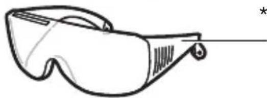
Line drawing of a pair of safety glasses with no text or symbolsR
* NOT STANDARD INCLUDED
natural_image
Icon of a person reading a book inside a circle, no text or symbols present
natural_image
Simple line drawing of a trash bin with crossed x- and circular base, no text or symbols present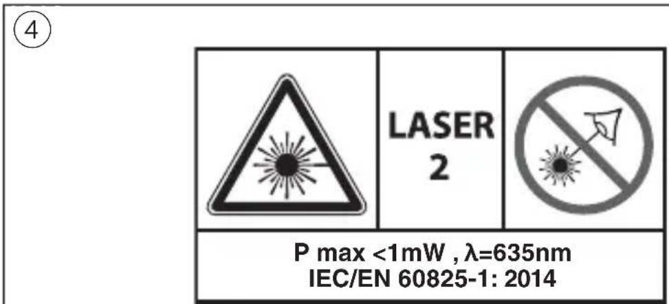
natural_image
Technical line drawing of a mechanical device with internal components and mounting holes (no text or symbols)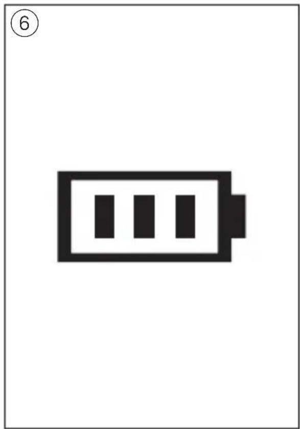
natural_image
Simple black-and-white battery icon with three vertical bars inside, labeled with number 6 (no text or symbols on the battery itself)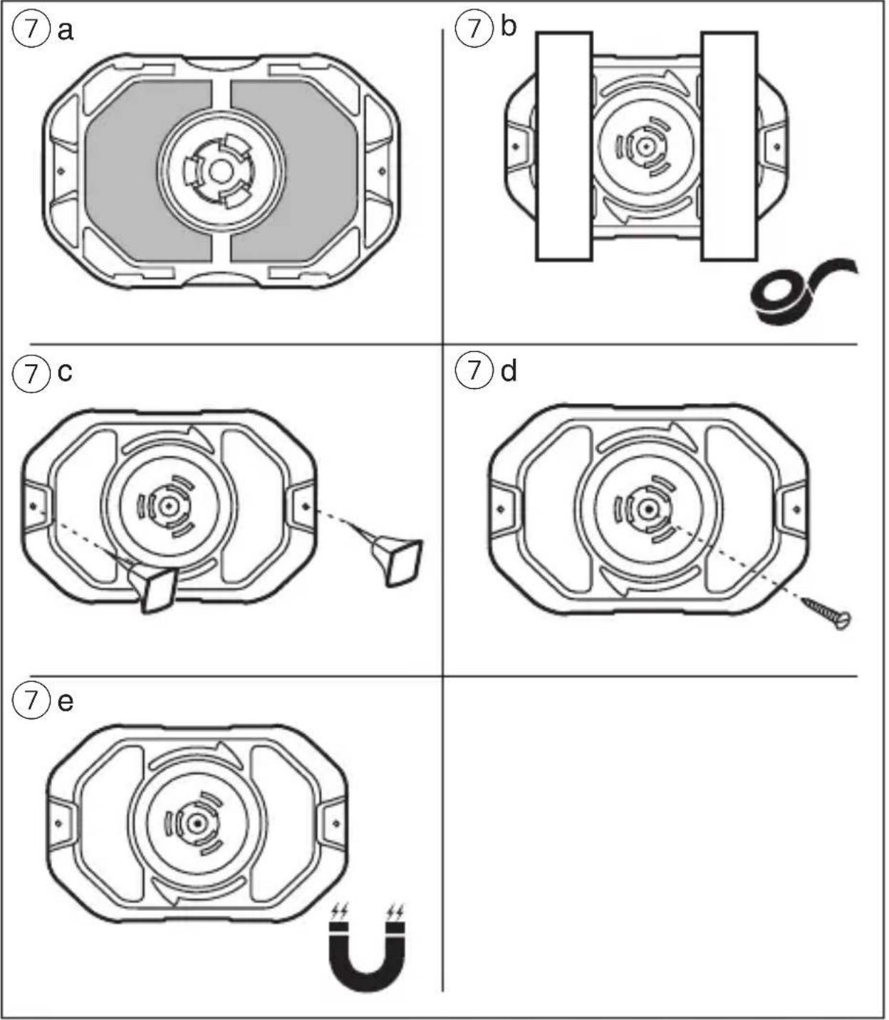
⑧
natural_image
Diagram showing a 3D object on a plane with shaded regions and a numbered circle (10) in the top-left corner (no text or symbols on the object itself)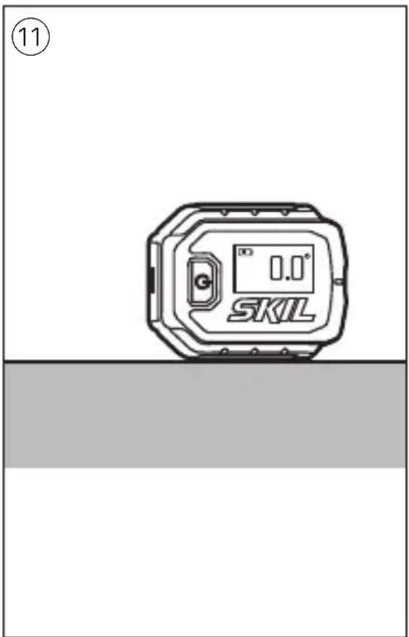
GB
Digital line laser level 1900
INTRODUCTION
- This tool is intended for aligning objects and/or marking desired cutting lines by means of a straight laser line projection; with the accessories supplied the tool can be used on a variety of surfaces
- This tool is intended to measure the angle between the working surface and true level
- The measuring tool is suitable exclusively for operation in enclosed working sites
• This tool is not intended for professional use - Save these instructions for future reference and include them with the measuring tool when giving it to a third party
TECHNICAL DATA
Working range 4.5m (approx.)*
Accuracy ±0.1^ (at 0^ and 90^ ), ±0.2^ (at other angles)
Operating temperature -0^ to +40^
Storage temperature -20°C to +70°C
Laser class 2
Laser type 635nm, < 1mW
Battery 3V; 2x 1.5V AAA (LR03) alkaline
Weight 0.056 kg
Dimensions (length x 61 x 48 x 34 mm width x height)
* Important: under unfavourable conditions (e.g. in bright light) the tool's working range will be reduced
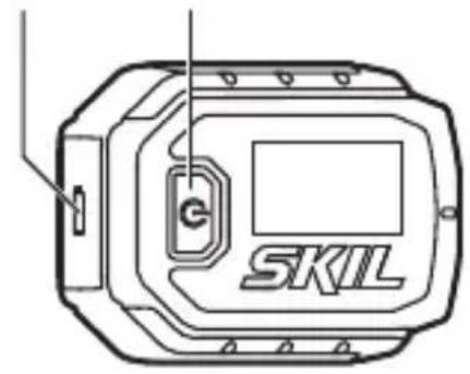
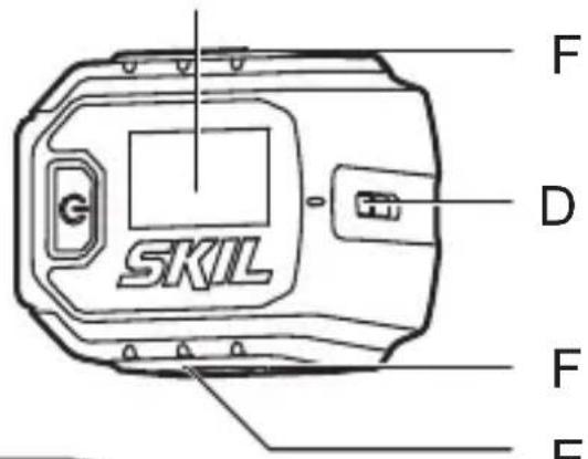
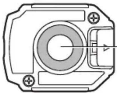
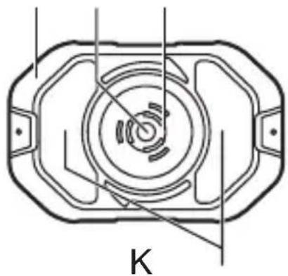
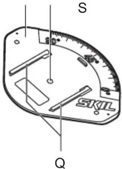
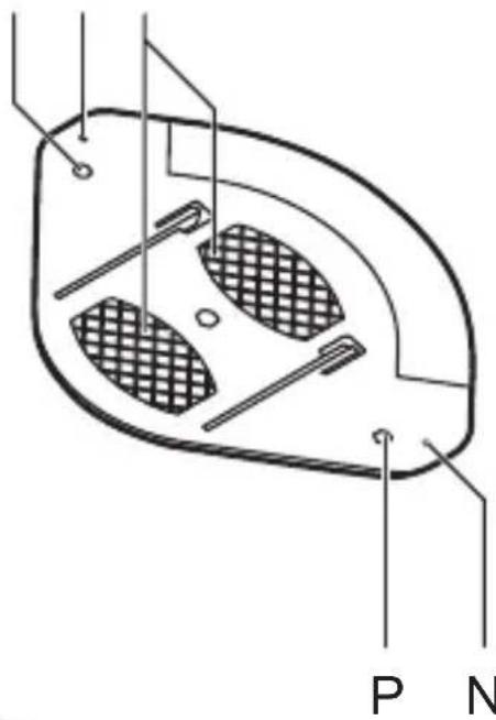
TOOL ELEMENTS ①
A Battery compartment cover
B Main button
C Display
D Exit opening for laser beam
E Magnetic edge
F Angle measurement base
G Slot for wall mount base
H Wall mount base
J Clip ring
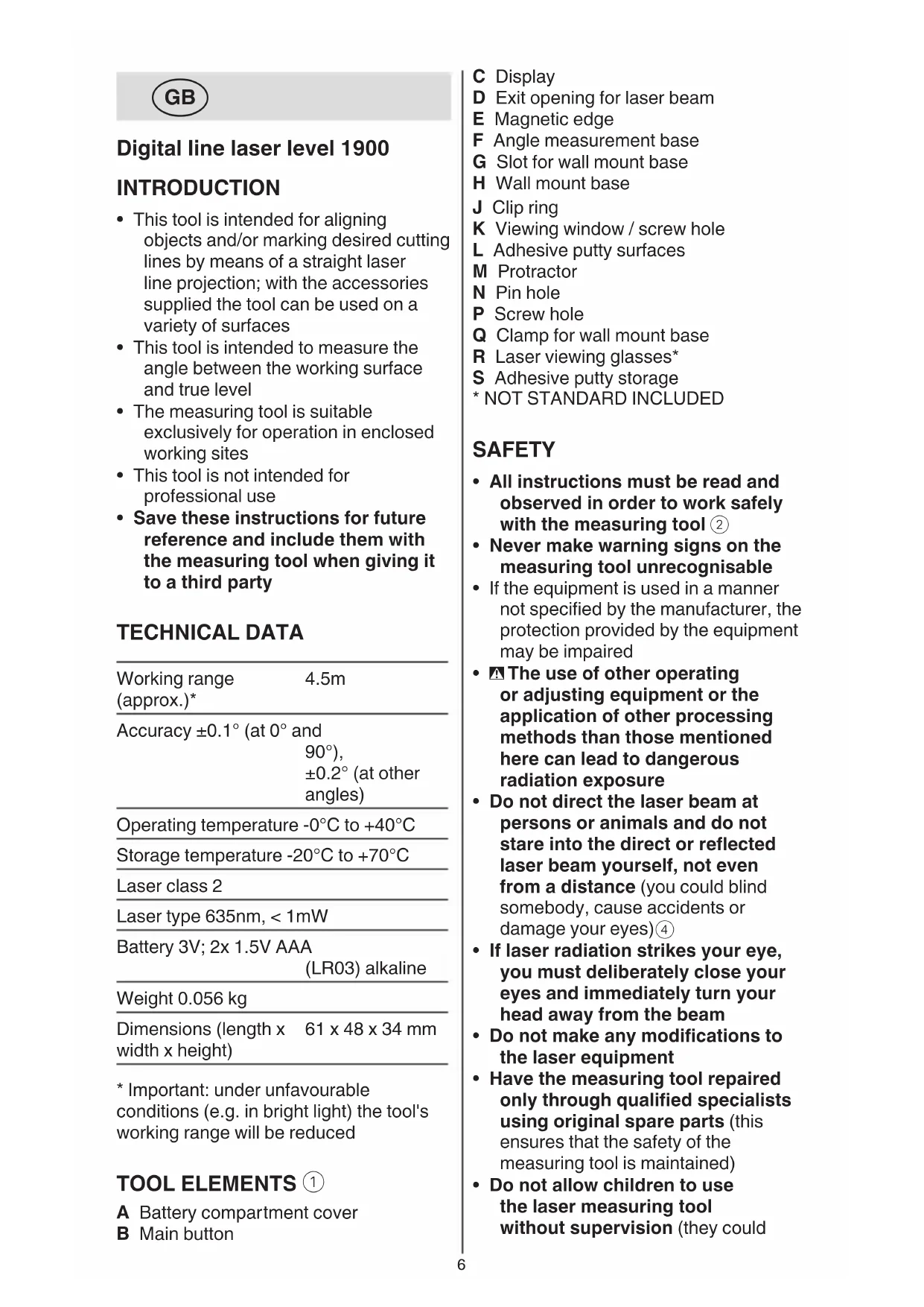
K Viewing window / screw hole
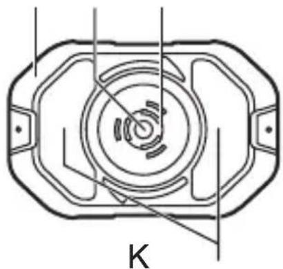
L Adhesive putty surfaces
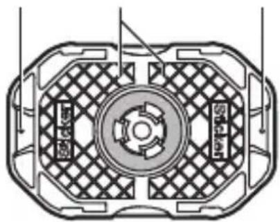
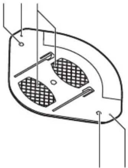
M Protractor
N Pin hole
P Screw hole
Q Clamp for wall mount base
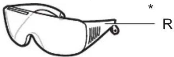
R Laser viewing glasses*
S Adhesive putty storage
* NOT STANDARD INCLUDED
SAFETY
- All instructions must be read and observed in order to work safely with the measuring tool ②
- Never make warning signs on the measuring tool unrecognisable
- If the equipment is used in a manner not specified by the manufacturer, the protection provided by the equipment may be impaired
- The use of other operating or adjusting equipment or the application of other processing methods than those mentioned here can lead to dangerous radiation exposure
- Do not direct the laser beam at persons or animals and do not stare into the direct or reflected laser beam yourself, not even from a distance (you could blind somebody, cause accidents or damage your eyes)④
- If laser radiation strikes your eye, you must deliberately close your eyes and immediately turn your head away from the beam
- Do not make any modifications to the laser equipment
- Have the measuring tool repaired only through qualified specialists using original spare parts (this ensures that the safety of the measuring tool is maintained)
- Do not allow children to use the laser measuring tool without supervision (they could
unintentionally blind other persons or themselves)
- Do not operate the measuring tool in explosive environments, such as in the presence of flammable liquids, gases or dusts (sparks can be created in the measuring tool which may ignite the dust or fumes)
- Keep the measuring tool away from cardiac pacemakers (the magnet inside the measuring tool generates a field that can impair the function of cardiac pacemakers)
- Keep the measuring tool away from magnetic data media and magnetically-sensitive equipment (the effect of the magnet can lead to irreversible data loss)
EXPLANATION OF SYMBOLS ON TOOL
② Read the instruction manual before use
③ Do not dispose of electric tools and batteries together with household waste material
④ Laser radiation / Do not stare into beam / Class 2 laser product
USE
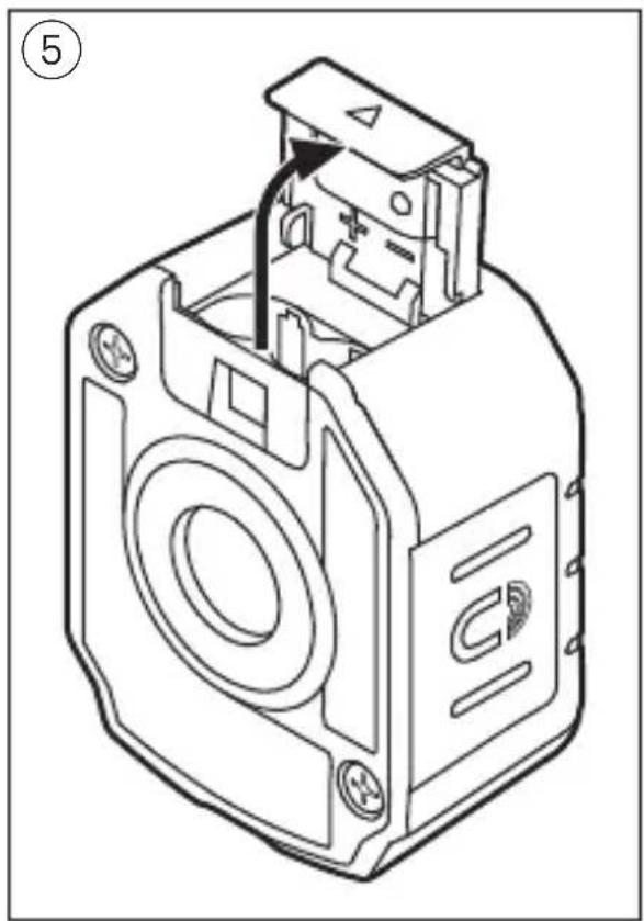
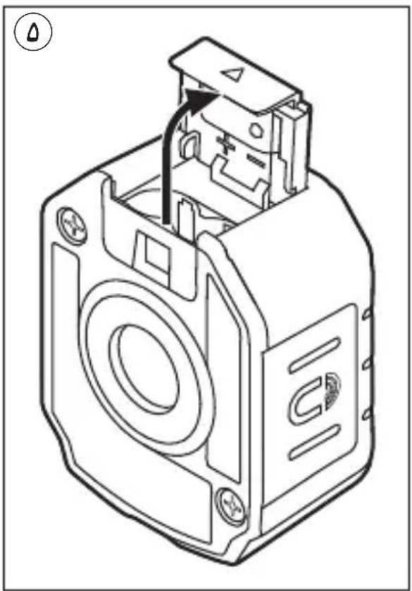
- Inserting/replacing the batteries ⑤
-alkali-manganese batteries are recommended for the measuring tool
-do not use rechargeable batteries
-remove cover A
-insert 2 x AAA batteries (pay attention to correct polarisation)
-always replace all batteries at the same time
-only use batteries from one brand and with the identical capacity
-mount cover A
-remove the batteries from the measuring tool when not using it for extended periods (when
storing for extended periods, the batteries can corrode and self-discharge)
- Battery level indicator ⑥
-during use the battery level indicator on the display indicates the remaining battery capacity
- On/off
-press and hold main button B to turn on the tool
! the laser beam is automatically activated when the tool is turned on
-press main button B briefly to turn on/off the laser beam
! with the laser beam turned off, the tool will automatically turn off after 5 minutes of inactivity
-press and hold main button B to turn off the tool
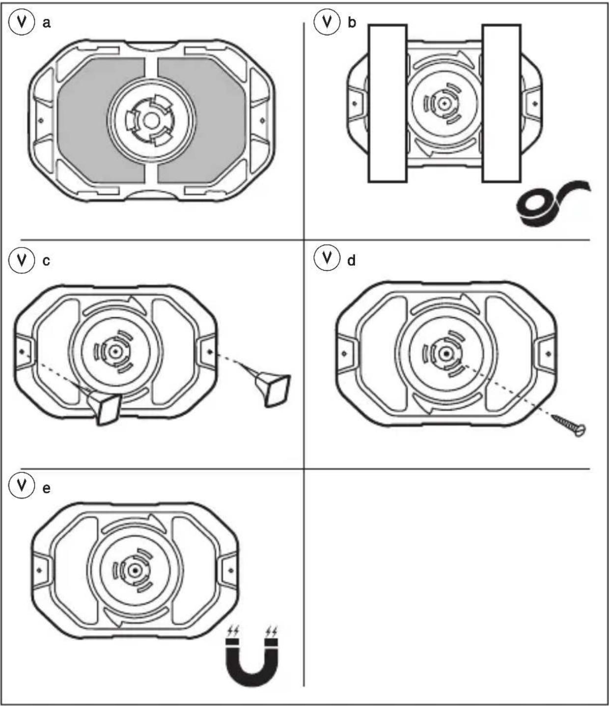
- Projecting on walls
-mark the point where the laser line should be projected
-place the wall mount base H with the marked point centered in the viewing window K
-mounting options:
1) use adhesive putty (included) on surfaces L ⑦ a or use tape (not included) to mount base on dry and clean surfaces ⑦ b
-the adhesive putty may used repeatedly
-to keep good adhesion, wash the putty frequently and store it in the adhesive putty storage S
-remove the wall-mount base from the wall slowly after using, any residue of the adhesive putty on the wall can be cleaned by rolling the adhesive putty over the residue
2) use pins (not included) through pin holes N to mount base on soft materials (plasterboard, soft wood) ⑦c
! be aware of sharp pins
3) use a screw or nail (not included) through viewing window / screw hole K to mount base ⑦d
4) use the magnet in base to mount it on ferrous metals ⑦e
-attach tool to wall mount base
! ensure that clip ring J clips into slot G on bottom of the tool
-rotate tool freely to the desired angle ⑧
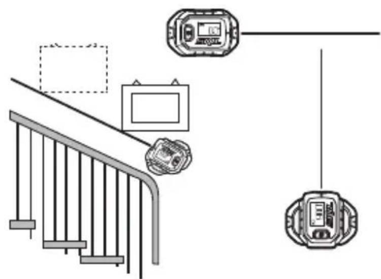
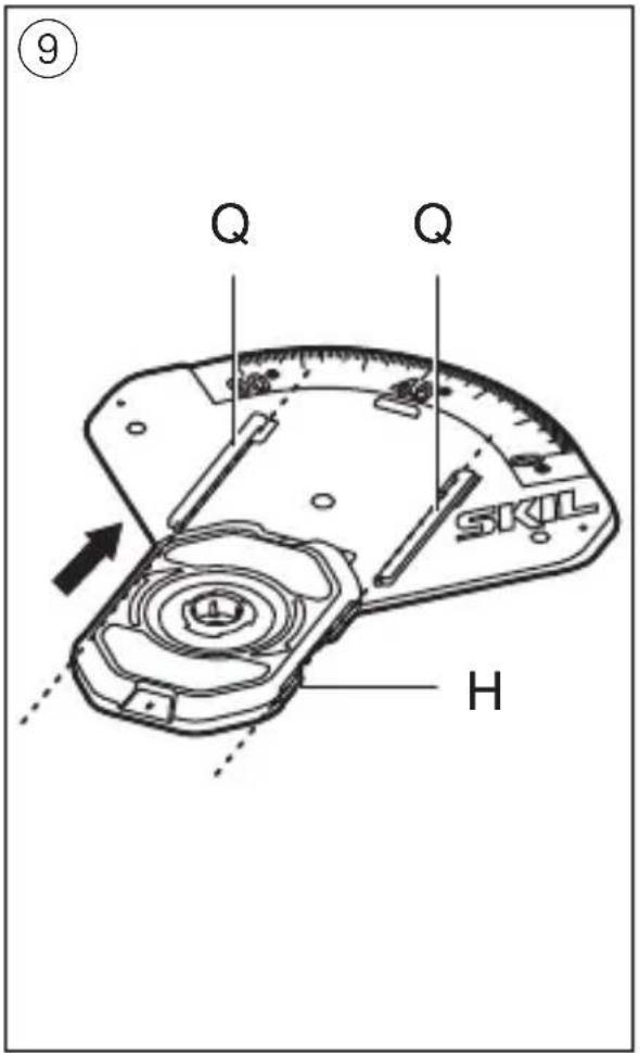
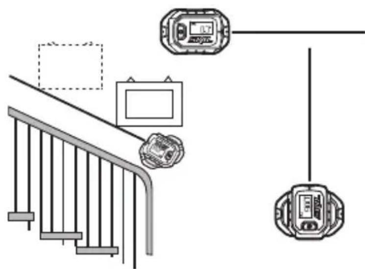
- Projecting on floors
-when projecting a laser line on the floor the digital angle indictation shows ---
-use the protractor M to adjust the laser line to any angle
-attach the wall mount base H to the protractor M as illustrated ⑨
-attach tool to wall mount base
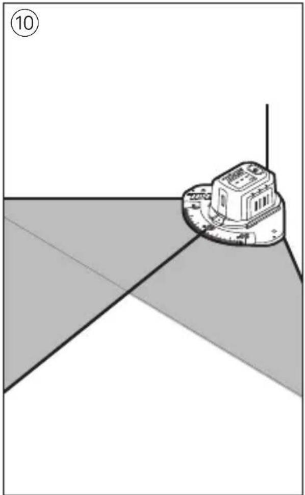
-position the protractor to a corner or an edge ⑩
-mounting options ⑦a, ⑦b, ⑦c, or ⑦d (with screw holes P) can also be used for setting the protractor on floors or ceiling
-turn on the tool
-rotate the tool to the desired angle
- Digital levelling
-with the laser beam turned off, the tool can be used as digital level
-place the tool with the angle measurement base F on the surface to be measured ⑪
-alternatively, use magnetic edge E to attach the tool to a ferrous surface
-the display shows the angle between the surface and absolute level
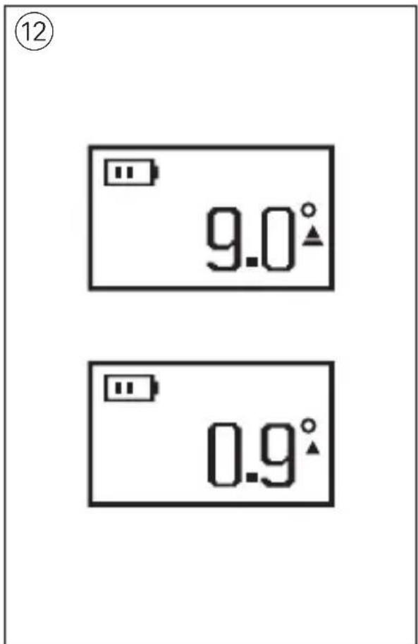
! if the display shows --- the tool is inclined to forward or backward too much and the measurement cannot be made
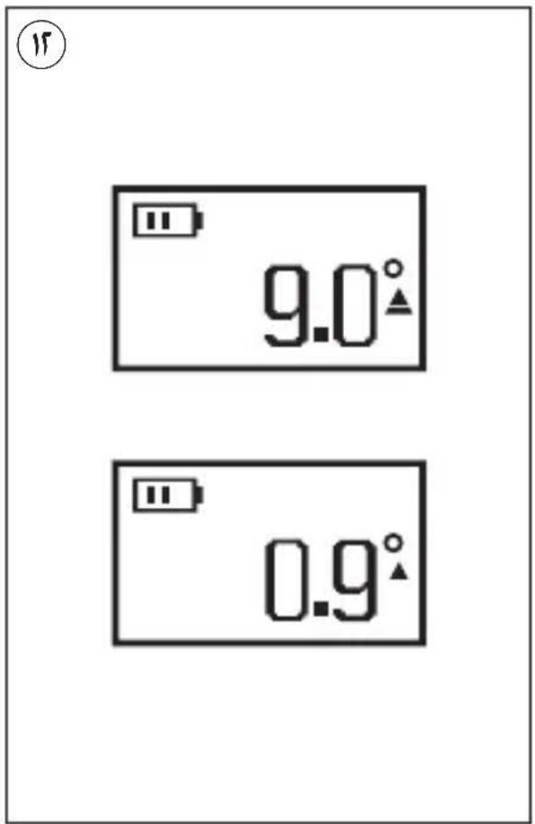
-to level or plumb the working surface, move the surface until the display shows 0° or 90°
-if the deviation is within ±10^ of 0^ and 90^ , fine-tuning arrows are shown which vary in direction and height relative to the target ^⑫
APPLICATION ADVICE
• Always use the centre of the laser line for marking (the width of the laser line changes with the distance)
- Laser viewing glasses ① (not standard included)
-laser viewing glasses R ① filter out the ambient light
-this makes the light of the laser appear brighter for the eyes
-do not use the laser viewing glasses as safety goggles (the laser viewing glasses are used for improved visualisation of the laser beam, but they do not protect against laser radiation)
-do not use the laser viewing glasses as sun glasses or in traffic (the laser viewing glasses do not afford complete UV protection and reduce colour perception)
MAINTENANCE / SERVICE
• This tool is not intended for professional use
- Protect the measuring tool against moisture and direct sun light
- Do not subject the measuring tool to extreme temperatures or variations in temperature (the accuracy of the measuring tool can be impaired)
-as an example, do not leave it in vehicles for long time
-allow the measuring tool to adjust to the ambient temperature before putting it into operation
- Avoid heavy impact to or falling down of the measuring tool
-damage to the measuring tool can impair its accuracy
- Keep the measuring tool clean at all times
- Do not immerse the measuring tool in water or other fluids
- Wipe off debris using a moist and soft cloth
- Do not use any cleaning agents or solvents
- Regularly clean the surfaces at the exit opening of the laser in particular, and pay attention to any fluff of fibres
- If the tool should fail despite the care taken in manufacturing and testing procedures, repair should be carried out by an after-sales service centre for SKIL power tools
-send the tool undismantled together with proof of purchase to your dealer or the nearest SKIL service station (addresses as well as the service diagram of the tool are listed on www.skil.com)
- Be aware that damage due to overload or improper handling of the tool will be excluded from the warranty (for the SKIL warranty conditions see www.skil.com or ask your dealer)
ENVIRONMENT
- Do not dispose of electric tools, batteries, accessories and packaging together with household waste material (only for EU countries) -in observance of European Directive
2012/19/EC on waste of electric and electronic equipment and its implementation in accordance with national law, electric tools that have reached the end of their life must be collected separately and returned to an environmentally compatible recycling facility
-symbol ③ will remind you of this when the need for disposing occurs! prior to disposal protect battery terminals with heavy tape to prevent short-circuit
F
S Haftendes Spachtellager
VEDLIKEHOLD / SERVICE
APKALPOŠANA / APKOPE
natural_image
Simple line drawing of a building on a roof with geometric shapes (no text or symbols)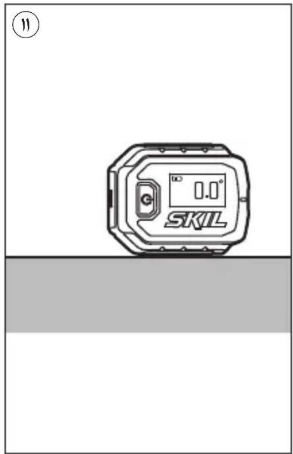
A
natural_image
Icon of a person reading a book inside a circle, with a clock symbol above (no text or symbols present)
natural_image
Simple line drawing of a trash bin with no text or symbols, featuring a circular icon above it (no text or symbols present)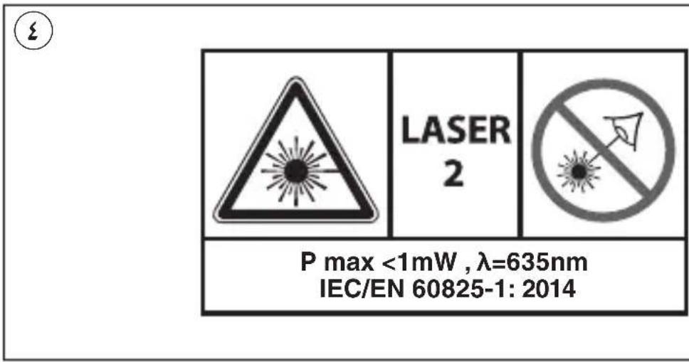
natural_image
Technical line drawing of a mechanical device with internal components and mounting holes (no text or symbols)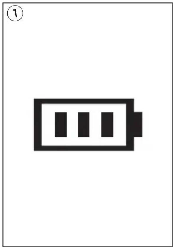
natural_image
Simple black-and-white battery icon with three vertical bars inside, no text or symbols present.1
A
B
C
natural_image
Technical diagram of a mechanical component with no visible text or symbolsE
G
HKJN
natural_image
Technical line drawing of a mechanical component with concentric circular features and labeled section K (no text or symbols beyond label)L

natural_image
Technical diagram of a mechanical component with no visible text or symbolsN
PNLM


Brand : SKIL
Model : 1900 AA
Category : Laser level