1911 DA - Laser level SKIL - Free user manual and instructions
Find the device manual for free 1911 DA SKIL in PDF.
| Product Type | Laser Level |
| Brand | Skil |
| Model | 1911 DA |
| Laser Class | 2 (IEC/EN 60825-1:2014) |
| Wavelength | 520 nm (green) |
| Self-Levelling Range | ±4° |
| Levelling Accuracy | ±0.5 mm/m |
| Working Range | Up to 20 m (under favorable conditions) |
| Levelling Time | ≤5 seconds |
| Battery Type | Li-Polymer, 3.7 V, 1200 mAh |
| Operating Time | Approx. 6 hours |
| Weight | 0.26 kg |
| Dimensions (L x W x H) | 71 x 61 x 77 mm |
| Tripod Mount | 1/4" female thread |
| Charging Interface | USB Micro-B (5V, ≥0.5A) |
| Operating Temperature | -5°C to +40°C |
| Storage Temperature | -20°C to +70°C |
| Additional Features | Auto-levelling, manual mode, additional projection marks on laser lines |
| Included Accessories | Charger cable (Micro-B) |
| Not Included | Tripod, clamp holder, laser viewing glasses, power supply |
| Maintenance | Clean with damp cloth; no solvents |
| Intended Use | Indoor, non-professional use |
Frequently Asked Questions - 1911 DA SKIL
User questions about 1911 DA SKIL
0 question about this device. Answer the ones you know or ask your own.
Ask a new question about this device
Download the instructions for your Laser level in PDF format for free! Find your manual 1911 DA - SKIL and take your electronic device back in hand. On this page are published all the documents necessary for the use of your device. 1911 DA by SKIL.
USER MANUAL 1911 DA SKIL
natural_image
Illustration of a SKIL brand device with visible internal components and branding (no text or symbols on the device itself)| GB | ORIGINAL INSTRUCTIONS | 6 |
| F | NOTICE ORIGINALE | 9 |
| D | ORIGINALBETRIEBSANLEITUNG | 13 |
| NL | ORIGINELE GEBRUIKSAANWIJZING | 17 |
| S | BRUKSANVISNING I ORIGINAL | 21 |
| DK | ORIGINAL BRUGSANVISNING | 25 |
| N | ORIGINAL BRUKSANVISNING | 28 |
| FIN | ALKUPERÄISET OHJEET | 32 |
| E | MANUAL ORIGINAL | 35 |
| P | MANUAL ORIGINAL | 39 |
| I | ISTRUZIONI ORIGINALI | 43 |
| H | EREDETI HASZNÁLATI UTASÍTÁS | 47 |
| CZ | PÜVODNÍM NÁVODEM K POUŽÍVÁNÍ | 51 |
| TR | ORÍJÍNAL İŞLETME TALİMATI | 55 |
| PL | INSTRUKCJA ORYGINALNA | 58 |
| RU | ПОДЛИННИК РУКОВОДСТВА ПОЭКСПЛУАТАЦИИ | 63 |
| UA | ОРИГИНАЛЬНА ІНСТРУКЦІЯЗ ЕКСПЛУАТАЦІЇ | 68 |
| GR | ПРОГОТОТУПО ОДНГІΩΝ ХРНЄНЗ | 72 |
| RO | INSTRUCTIUNI DE FOLOSIREORIGINALE | 77 |
| BG | ОРИГИНАЛНО РЬКОВОДСТВОЗА ЕКСПЛОАТАЦИЯ | 80 |
| SK | РОГОВОДНЫ NÁVOD NA POUŽITIE | 85 |
| HR | ORIGINALNE UPUTE ZA RAD | 89 |
| SRB | ORIGINALNO UPUTSTVO ZA RAD | 92 |
| SLO | IZVIRNA NAVODILA | 96 |
| EST | ALGUPÄRANE KASUTUSJUHEND | 99 |
| LV | ORIGINÄLÄ LIETOŠANAS PAMÄCĪBA | 103 |
| LT | ORIGINALI INSTRUKCIJA | 107 |
| MK | ИЗВОРНО УПАТСТВО ЗА РАБОТА | 110 |
| AL | UDHËZIMET ORIGJINALE | 115 |
| AR | дليل الاستعمال | 127 |
| FA | راهنماي اصلی | 129 |
1
natural_image
Icon of a person reading a book inside a circle, no text or symbols present
text_image
③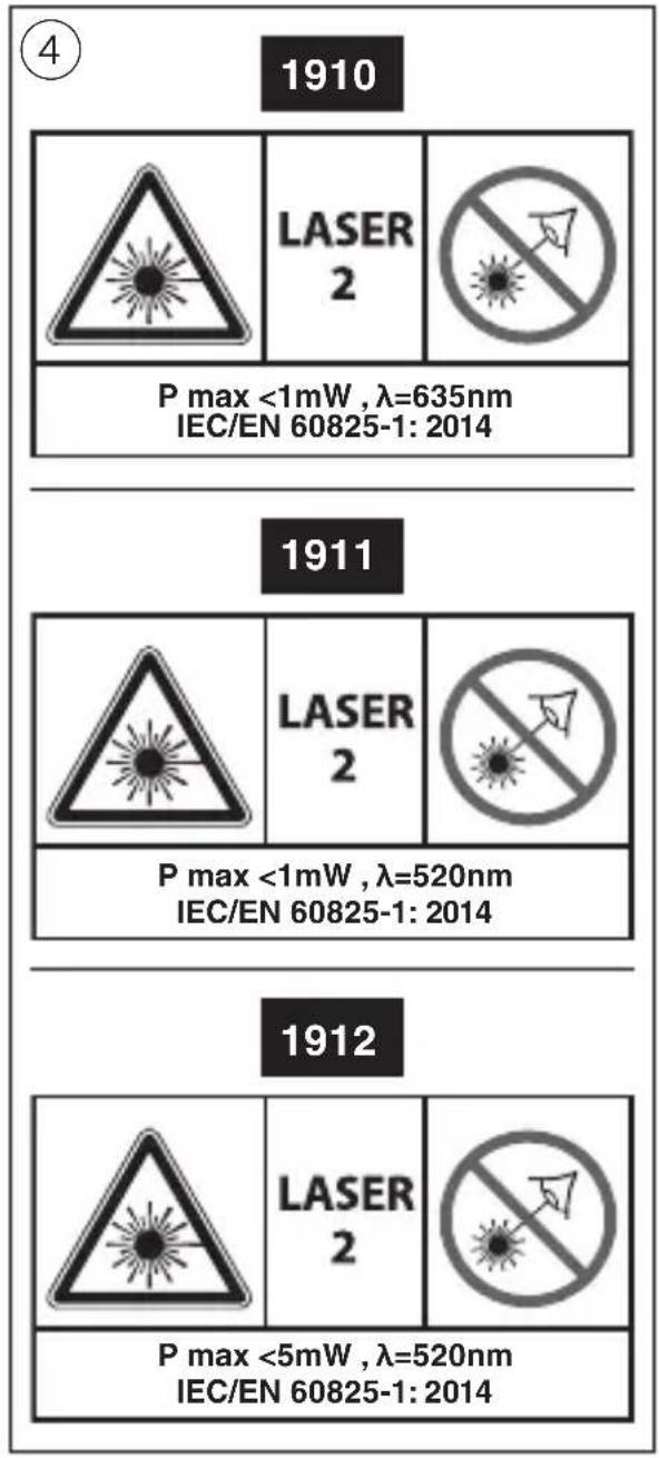
text_image
4 1910 LASER 2 P max <1mW , λ=635nm IEC/EN 60825-1: 2014 1911 LASER 2 P max <1mW , λ=520nm IEC/EN 60825-1: 2014 1912 LASER 2 P max <5mW , λ=520nm IEC/EN 60825-1: 2014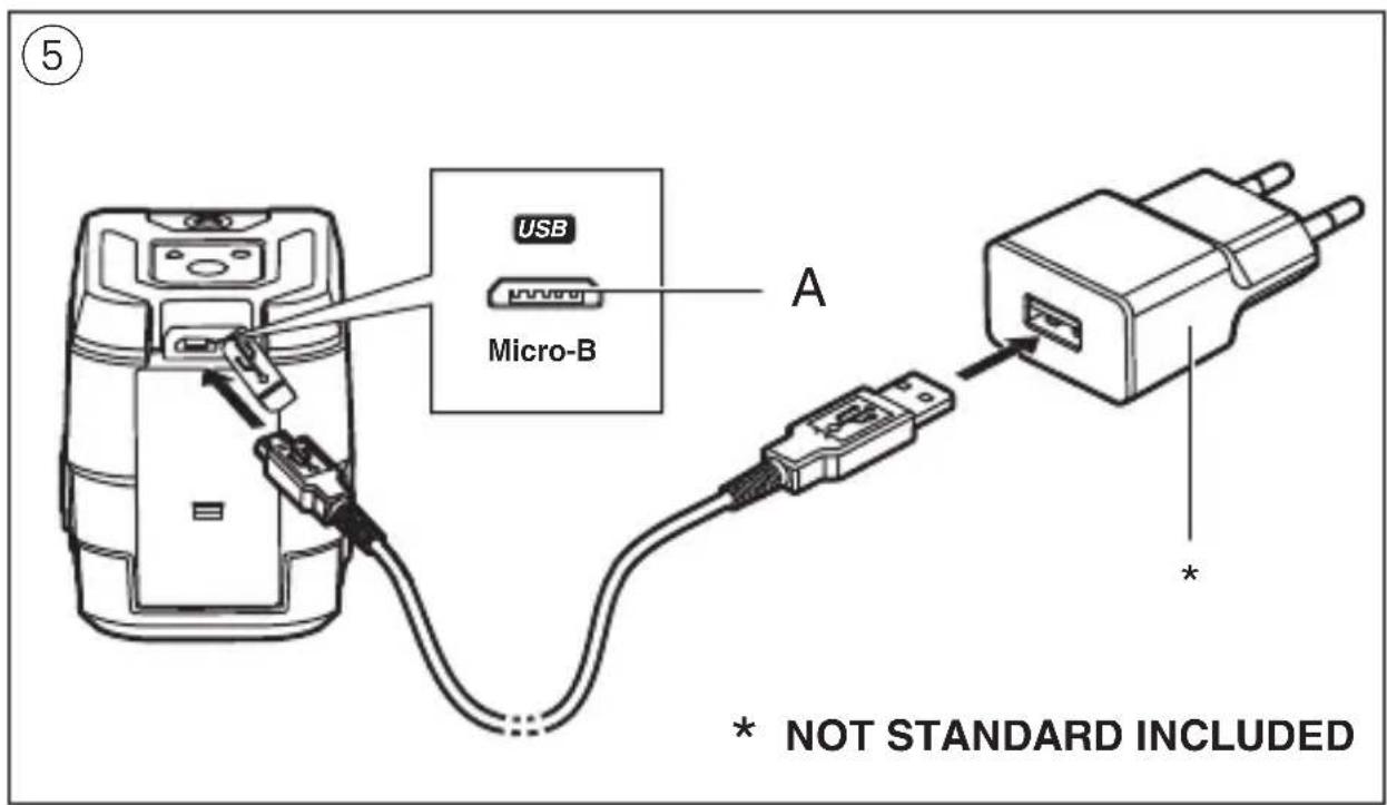
text_image
USB Micro-B A * * NOT STANDARD INCLUDED
⑦ a
natural_image
Diagram showing two mobile phone modules with dashed circular boundaries and crosshairs, no text or symbols present.⑦ b
text_image
Diagram showing three identical devices with X marks and a checkmark, likely indicating selection or confirmation.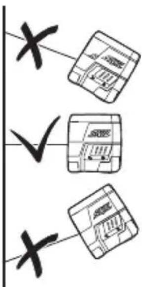
text_image
x ✓ x⑧ a
natural_image
Technical line drawing of a mechanical device with no visible text or symbols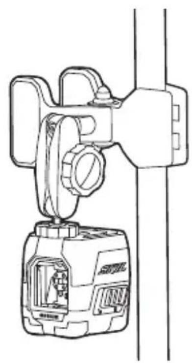
natural_image
Technical line drawing of a mechanical device with internal components and mounting bracket (no text or symbols)⑧ b
natural_image
Technical line drawing of a mechanical device with a handle and valve, showing internal components and a close-up view (no text or symbols)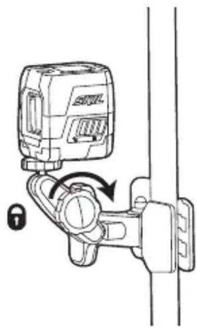
natural_image
Diagram of a mechanical device with a lock and adjustment knob, no text or symbols presentCross-line laser 1910/1911/1912
INTRODUCTION
- The measuring tool is intended for determining and checking horizontal and vertical lines
- The measuring tool is suitable exclusively for operation in enclosed working sites
• This tool is not intended for professional use - Save these instructions for future reference and include them with the measuring tool when giving it to a third party
TECHNICAL DATA
| Working range (approx.)* | 15m (1910), 20m (1911/1912) |
| Levelling accuracy ±0.5 mm/m | |
| Self-levelling range ± 4° | |
| Levelling time ≤5 seconds | |
| Operating temperature | -5°C to +40°C |
| Storage temperature-20°C to +70°C | |
| Relative humidity (max.) | 90% |
| Laser class 2 | |
| Laser type 635nm (1910), 520nm (1911/1912) | |
| Tripod mount 1/4" | |
| Battery Li-Polymer, 3.7V, 1200mAh | |
| Operating time 16hrs (1910), 6hrs (1911/1912) | |
| Weight | 0.26 kg |
| Dimensions (length x width x height) | 71 x 61 x 77 mm |
* Important: under unfavourable conditions (e.g. in bright light) the tool's working range will be reduced
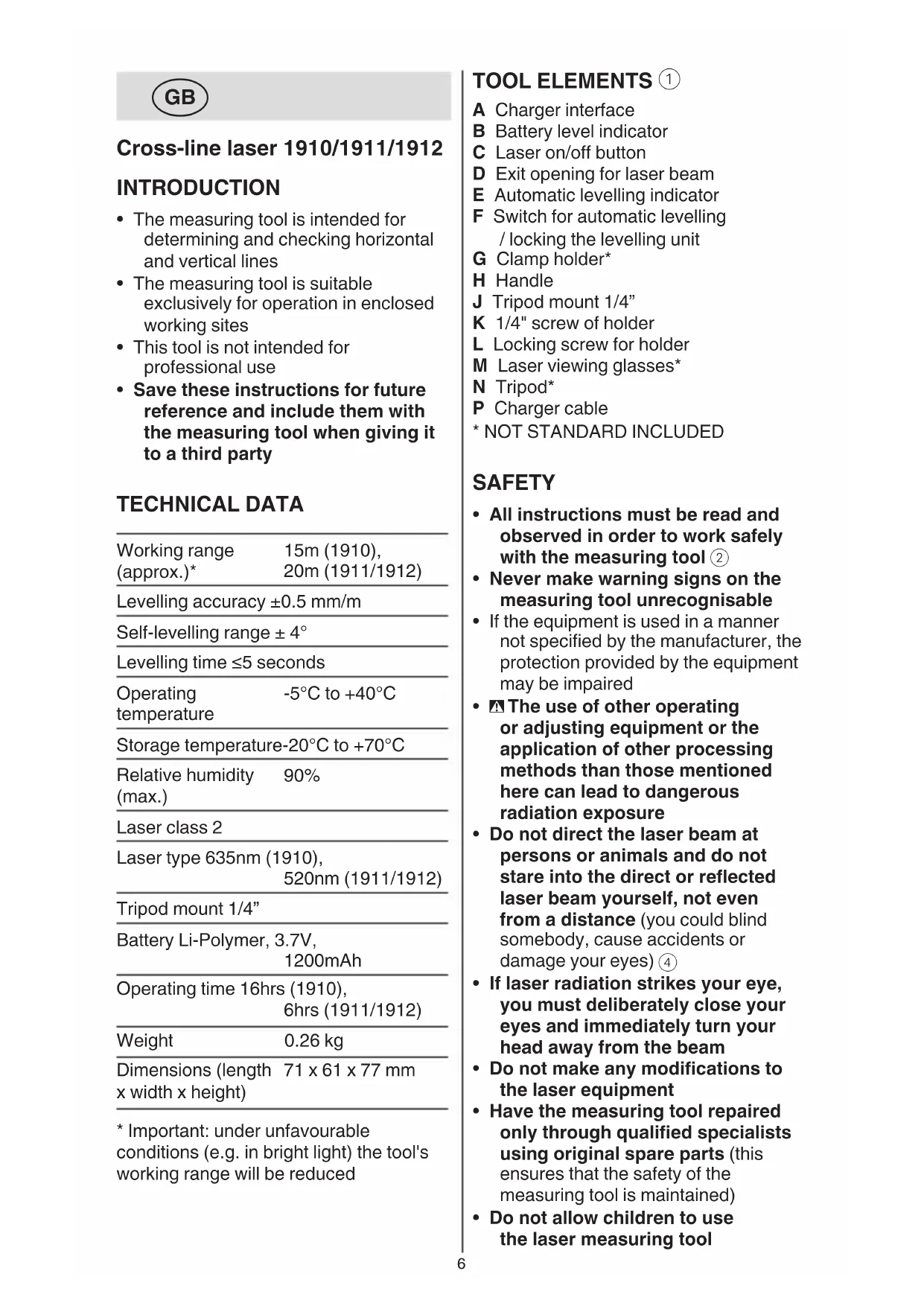
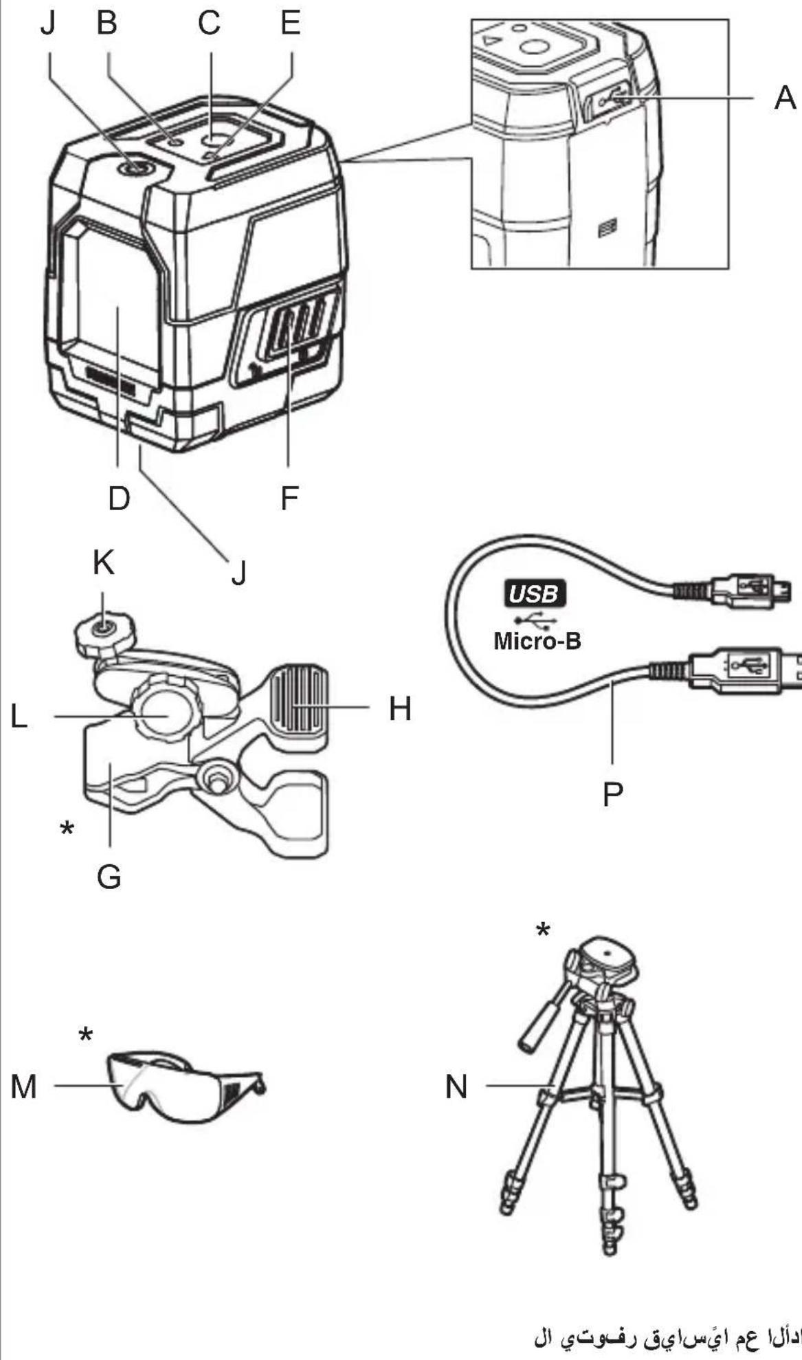
TOOL ELEMENTS ①
A Charger interface
B Battery level indicator
C Laser on/off button
D Exit opening for laser beam
E Automatic levelling indicator
F Switch for automatic levelling / locking the levelling unit
G Clamp holder*
H Handle
J Tripod mount 1/4"
K 1/4" screw of holder
L Locking screw for holder
M Laser viewing glasses*
N Tripod*
P Charger cable
* NOT STANDARD INCLUDED
SAFETY
- All instructions must be read and observed in order to work safely with the measuring tool ②
- Never make warning signs on the measuring tool unrecognisable
- If the equipment is used in a manner not specified by the manufacturer, the protection provided by the equipment may be impaired
- The use of other operating or adjusting equipment or the application of other processing methods than those mentioned here can lead to dangerous radiation exposure
- Do not direct the laser beam at persons or animals and do not stare into the direct or reflected laser beam yourself, not even from a distance (you could blind somebody, cause accidents or damage your eyes) ④
- If laser radiation strikes your eye, you must deliberately close your eyes and immediately turn your head away from the beam
- Do not make any modifications to the laser equipment
- Have the measuring tool repaired only through qualified specialists using original spare parts (this ensures that the safety of the measuring tool is maintained)
- Do not allow children to use the laser measuring tool
without supervision (they could unintentionally blind other persons or themselves)
- Do not operate the measuring tool in explosive environments, such as in the presence of flammable liquids, gases or dusts (sparks can be created in the measuring tool which may ignite the dust or fumes)
EXPLANATION OF SYMBOLS ON TOOL
② Read the instruction manual before use
③ Do not dispose of electric tools and batteries together with household waste material
④ Laser radiation / Do not stare into beam / Class 2 laser product
USE
- Charging battery ⑤
! the battery supplied is partially charged (to ensure full capacity of the battery, completely charge the battery in the battery charger before using your power tool for the first time)
! read and follow the instruction delivered with the charger or power supply
-only use a charger or power supply which has an output voltage of 5V and output current of ≥0.5A
-connect charger cable P with both charger or power supply (not standard included) and charger interface A
-indicator B is blinking RED indicating that the battery is being charged and the current battery capacity enables the tool to be operated for 30 minutes or less
-indicator B is blinking YELLOW indicating that the battery is being charged and the current battery capacity enables the tool to be operated for more than 30 minutes
-indicator B is blinking GREEN indicating that the battery is charged for more than 90% of full capacity
-indicator B turns GREEN continuously when the battery is fully charged
- Battery level indicator B ①
-during use the battery level indicator
B indicates the remaining battery capacity with different colors
-GREEN indicates more than 40% of full capacity
-YELLOW indicates less than 40% of full capacity
-RED indicates only 30 minutes left before turning off automatically
- On/off ⑥
-to switch on the measuring tool, press either laser button C when using it WITHOUT automatic leveling, or slide switch F into position ⑥ a to unlock the levelling unit when using it WITH automatic levelling
! immediately after switching on, the measuring tool sends a laser beam out of the exit opening D
! do not point the laser beam at persons or animals and do not stare into the laser beam yourself, not even from a large distance
-to switch off the measuring tool, press either laser button C when using it WITHOUT automatic leveling, or slide switch F into position ⑥b to lock the levelling unit when using it WITH automatic levelling
-do not leave the switched on measuring tool unattended and switch the measuring tool off after use (other persons could be blinded by the laser beam)
-when not using the measuring tool, switch it off in order to extend the battery life
• Working with automatic levelling
-position the measuring tool on a level, firm support or attach it to tripod N or to the clamp holder G
-slide switch F to position ⑥a
-if the automatic levelling function is not possible, e.g. because the surface on which the measuring tool stands deviates by more than 4^ from the horizontal plane, the laser lines flash and indicator E turns red
-if this is the case, set up the measuring tool in a level position and wait for the self-levelling to take place
-as soon as the measuring tool is once again within the self-levelling
range of ±4^ , the laser lines light up continuously and indicator E turns off
-when not within the self-levelling range of ±4^ , working with automatic levelling is not possible, because it cannot be assured that the laser lines run at a right angle to each other
-in case of ground vibrations or position changes during operation, the measuring tool is automatically levelled in again
-to avoid errors, check the position of the horizontal and vertical laser line with regard to the reference points upon re-levelling
- Working without automatic levelling
-slide switch F to position ⑥b
-push laser button C to turn on the laser beam
-indicator E turns red continuously in this mode
-when automatic levelling is switched off, you can hold the measuring tool freely in your hand or place it on an inclined surface
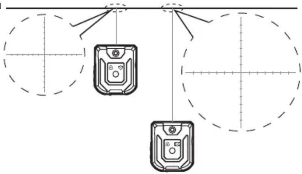
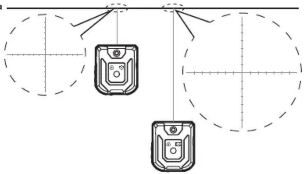
- Working with additional marks on the laser lines (1911) ⑦
-the measuring tool projects additional marks at equal intervals on the laser lines for better assistance when hanging pictures, etc. on walls
-if you move the tool away from the projection surface, the distance and length of the additional marks will increase, and decrease if you move the tool towards the projection surface ⑦a
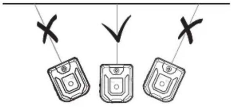
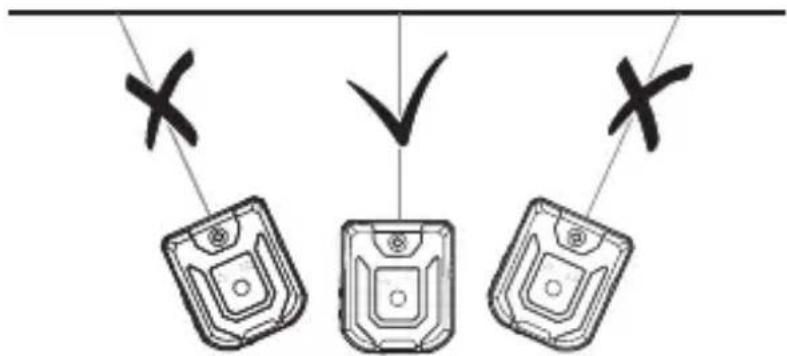
-make sure that you do not project the laser beam under an angle, otherwise the additional marks will not be projected at equal intervals ⑦b
APPLICATION ADVICE
• Always use the centre of the laser line for marking (the width of the laser line changes with the distance)
- Laser viewing glasses ① (not standard included)
-laser viewing glasses M ① filter out the ambient light
-this makes the light of the laser appear brighter for the eyes
-do not use the laser viewing glasses as safety goggles (the laser viewing glasses are used for improved visualisation of the laser beam, but they do not protect against laser radiation)
-do not use the laser viewing glasses as sun glasses or in traffic (the laser viewing glasses do not afford complete UV protection and reduce colour perception)
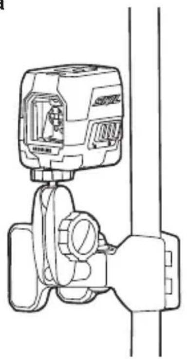
- Working with the clamp holder (not standard included)⑧
-with clamp holder G you can attach the measuring tool to different objects having a thickness up to 60 mm, such as pipes or edges of a table
-mount the the 14 " screw K to the 14 " tripod mount J on top or bottom of the tool ⑧a
! do not overtighten the measuring tool, otherwise it can become damaged
-use handle H to open the clamp and mount it to the desired location by releasing handle H again
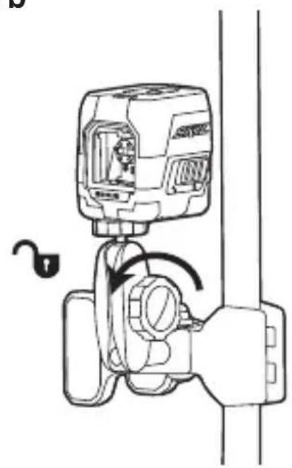
-loosen knob L ⑧b to adjust the position of the tool and the projection of the laser beam -after adjustment, tighten knob L
- Working with the tripod (not standard included)
-tripod N ① offers a stable, height-adjustable measuring support
-place the measuring tool via tripod mount J onto the 1/4" male thread of the tripod and screw the locking screw of the tripod tight
MAINTENANCE / SERVICE
• This tool is not intended for professional use
- Protect the measuring tool against moisture and direct sun light
- Do not subject the measuring tool to extreme temperatures or variations in temperature (the accuracy of the measuring tool can be impaired)
-as an example, do not leave it in vehicles for long time
-allow the measuring tool to adjust to the ambient temperature before putting it into operation
- Avoid heavy impact to or falling down of the measuring tool
-damage to the measuring tool can impair its accuracy -after heavy impact or shock, compare the laser lines with a known horizontal or vertical reference line
- Push switch F ① into locking position ⑥ when transporting the measuring tool (this locks the levelling unit, which can be damaged in case of intense movement)
- Keep the measuring tool clean at all times
- Do not immerse the measuring tool in water or other fluids
- Wipe off debris using a moist and soft cloth
- Do not use any cleaning agents or solvents
- Regularly clean the surfaces at the exit opening of the laser in particular, and pay attention to any fluff of fibres
- If the tool should fail despite the care taken in manufacturing and testing procedures, repair should be carried out by an after-sales service centre for SKIL power tools
-send the tool undismantled together with proof of purchase to your dealer or the nearest SKIL service station (addresses as well as the service diagram of the tool are listed on www.skil.com)
- Be aware that damage due to overload or improper handling of the tool will be excluded from the warranty (for the SKIL warranty conditions see www.skil.com or ask your dealer)
ENVIRONMENT
- Do not dispose of electric tools, batteries, accessories and packaging together with household waste material (only for EU countries)
-in observance of European Directive 2012/19/EC on waste of electric and electronic equipment and its implementation in accordance with
national law, electric tools that have reached the end of their life must be collected separately and returned to an environmentally compatible recycling facility
-symbol ③ will remind you of this when the need for disposing occurs

Laser croix 1910/1911/1912
INTRODUCTION
| Lasertype 635 nm (1910),520 nm (1911/1912) |
Stativholder 1/4"
Batteri Lithium-polymer, 3,7 V, 1200 mAh
Driftstid 16 t (1910), 6 t (1911/1912)
Vægt 0,26 kg
VEDLIKEHOLD / SERVICE
A Rozhraní nabíječky
APKALPOŠANA / APKOPE
natural_image
Line drawing of a mechanical device with a handle and valve, no text or symbols present
natural_image
Diagram of a lock mechanism with a device and lock symbol, showing no text or labels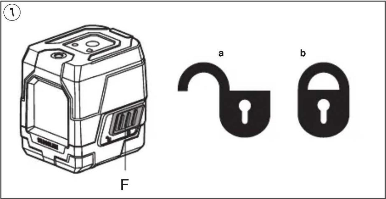
V
natural_image
Diagram showing two devices with directional arrows and crosshairs, no text or symbols presentV
text_image
Diagram showing three devices with X marks and a checkmark, likely indicating selection or confirmation.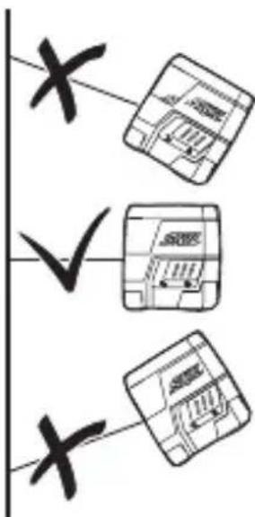
text_image
x ✓ x
natural_image
Icon of a person reading a book inside a circle, no text or symbols present
text_image
Diagram of a trash bin with crossed and unbroken lines indicating no waste or discharge, marked with a circled number 4.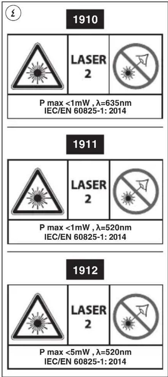
text_image
1910 P max <1mW , λ=635nm IEC/EN 60825-1: 2014 1911 P max <1mW , λ=520nm IEC/EN 60825-1: 2014 1912 P max <5mW , λ=520nm IEC/EN 60825-1: 2014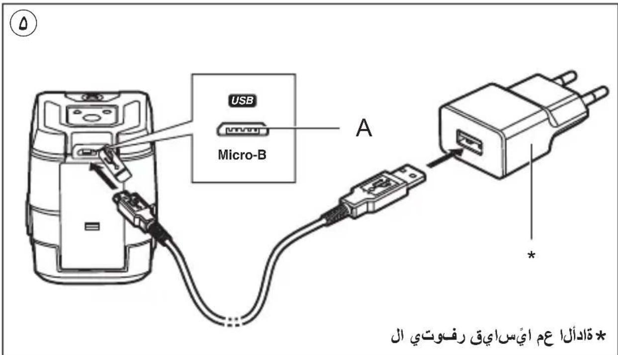
text_image
USB Micro-B A * تَادُّلَا عَمْ أَيْسَ اِيْق رفُوْتِي الْ1
* قادألا عم ايّسایق رفوتي ال
الليز المتقطع
1910
1911
1912

text_image
SKIL 30.000000000000000000000000000000000000000000000000000000000000000000000000000000000000
text_image
دليل الاستعمال AR راهنماي اصلی FA