USER MANUAL B43 BT MCCULLOCH
natural_image
Silhouette of a selfie stick with a headband and wristpin (no text or symbols)
B43BT
EAC

EN Operator's manual 11-22
natural_image
Two illustrations of workers in protective gear: one using a tool to clean vegetation, the other using a metal detector (no text or symbols present)

natural_image
Line drawing of a handheld device with a black arrow pointing to the handle (no text or symbols)

natural_image
Technical line drawing of a mechanical tool or device with a base mount (no text or symbols)

natural_image
Technical line drawing of a mechanical assembly with gear and shaft components (no text or symbols)
natural_image
Technical line drawing of a mechanical device with a tool and pipe connection (no text or symbols)
natural_image
Illustration showing two different techniques for adjusting a wristband, with arrows indicating movement direction (no text or symbols present)

natural_image
Technical line drawing of a mechanical component with mounting holes and housing (no text or symbols)
natural_image
Two technical line drawings of mechanical components: a circular gear-like part and a curved blade with internal features (no text or symbols)
natural_image
Technical line drawing of a mechanical component with three views: top is a symmetrical shape, middle is a curved bracket with a central hole, and bottom is a circular symbol with a diagonal line (no text or labels)
natural_image
Technical line drawing of a mechanical component with a circular base and a flanged top (no text or symbols)
natural_image
Diagram of a tool interacting with a mechanical part, showing motion direction (no text or symbols)
natural_image
Illustration showing a tool and a hand holding a tool with a curved arrow indicating motion (no text or symbols)
natural_image
Three technical illustrations of industrial components: a spool, a fan with a circular button, and a coiled wire (no text or symbols)
natural_image
Diagram of a tool pressing down on a mechanical part with an arrow indicating motion (no text or symbols)
natural_image
Technical line drawing of a mechanical device with wiring and a separate schematic view (no text or symbols)
natural_image
Technical diagram of a mechanical assembly with no visible text or symbols
natural_image
Technical line drawing of a mechanical device with a lever and attached component (no text or symbols)
natural_image
Technical illustration of a mechanical assembly with exploded view and component details (no text or symbols)
flowchart
graph TD
    A["Tool"] --> B["Component 1"]
    B --> C["Component 2"]
    C --> D["Component 3"]
    D --> E["Component 4"]
    E --> F["End"]
natural_image
Illustration showing two steps of a person's belt buckle being adjusted, with arrows indicating the motion (no text or symbols present)
natural_image
Line drawing of a cartoon character wearing a hat with downward arrows indicating pressure or stress (no text or symbols)
natural_image
Diagram of a circular mechanical component with internal segments and an inset showing a fastening mechanism (no text or symbols)

natural_image
Line drawing of a mechanical device with a black arrow pointing to a component (no text or symbols)
natural_image
Technical line drawing of a mechanical device with a circular symbol labeled 'H' (no text or symbols on the device itself)
natural_image
Illustration of a person in safety gear handling a box, no text or symbols present
natural_image
Diagram of an electric motor with a cross mark and warning symbol (no text or labels)
natural_image
Line drawing of a mechanical device with a black arrow pointing to a component (no text or symbols)
natural_image
Line drawing of a handheld device with a black arrow pointing to the handle (no text or symbols)
flowchart
graph TD
    A["Plant"] --> B["Leafy Plant"]
    B --> C["Plant"]
    C --> D["Leafy Plant"]
    D --> E["Plant"]
    E --> F["Leafy Plant"]
    F --> G["Plant"]
    G --> H["Leafy Plant"]
    H --> I["Plant"]
    I --> J["Leafy Plant"]
    J --> K["Plant"]
    K --> L["Leafy Plant"]
    L --> M["Plant"]
    M --> N["Leafy Plant"]
    N --> O["Plant"]
    O --> P["Leafy Plant"]
    P --> Q["Plant"]
    Q --> R["Leafy Plant"]
    R --> S["Plant"]
    S --> T["Leafy Plant"]
    T --> U["Plant"]
    U --> V["Leafy Plant"]
    V --> W["Plant"]
    W --> X["Leafy Plant"]
    X --> Y["Plant"]

natural_image
Line drawing of a person walking on a path with trees and a dashed line indicating a path (no text or symbols)
natural_image
Illustration showing a tree pruning technique with a stick figure observing it (no text or symbols)
natural_image
Illustration showing a tree pruning method and a stick figure with a spiral (no text or symbols)
natural_image
Simple line drawing of a person holding a circular object with a downward arrow, no text or symbols present
natural_image
Simple line drawings of a tree stump, a circular saw, and a stick figure (no text or symbols)
natural_image
Diagram showing a wooden saw cutting through a gear with a moving gear to cut the tree trunk, and a hand operating a tool (no text or symbols present)
natural_image
Illustration of a person using a tool to spread soil or plants around a central plant with arrows indicating flow direction (no text or symbols)
natural_image
Simple line drawing of a grassy field with a diagonal tool, no text or symbols present
natural_image
Simple line drawing of a grassy field with a tool and a small object, no text or symbols present
natural_image
Simple line drawing of a grassy field with a small utility pole and a flat support structure (no text or symbols)
natural_image
Illustration of a person using a pulley system with motion arrows indicating direction (no text or symbols)
natural_image
Line drawing of hands holding a mechanical component with a curved arrow indicating rotation (no text or symbols)
natural_image
Illustration showing hands assembling a mechanical component with a valve and base (no text or symbols)
natural_image
Technical line drawing of a mechanical component with mounting holes and internal cavities (no text or symbols)
natural_image
Diagram of a plug assembly with a socket and cable, showing no text or symbols
natural_image
Technical line drawing of a mechanical component with an arrow indicating direction (no text or symbols)
natural_image
Technical line drawing of a spark plug with threaded end and shaft (no text or symbols)
natural_image
Illustration of a person in protective gear using a tool to measure bone structure, with a magnified inset showing bone detail (no text or symbols)
natural_image
Simple line drawing of a mechanical clamp or bracket with a circular head and curved base (no text or symbols)

natural_image
Diagram showing two mechanical components with directional arrows indicating movement or force (no text or symbols)

natural_image
Diagram of a tool pressing down on a mechanical part with an arrow indicating motion (no text or symbols)
Contents
INTRODUCTION.... 11
SAFETY....12
ASSEMBLY.... 16
OPERATION....16
MAINTENANCE....19
TRANSPORTATION AND STORAGE.... 21
TECHNICAL DATA....21
ACCESSORIES....22
INTRODUCTION
Operator's manual
The initial language of this operator's manual is English. Operator's manuals in other languages are translations from English.
Overview
(Fig. 1)
- Blade
- Grease filler cap, bevel gear
- Bevel gear
- Cutting attachment guard
- Shaft
-
Start throttle button
-
Stop switch
-
Throttle trigger
-
Throttle lockout
-
Suspension ring
-
Cylinder cover
-
Starter rope handle
-
Fuel tank
-
Choke control
-
Air filter cover
-
Nut
-
Support flange
-
Support cup
-
Protective guard
-
Handlebar clamp
-
Operator's manual
-
Transport guard
-
Socket Wrench
-
Hex wrench
-
Harness
-
Trimmer head
-
Air purge
-
Washer
-
Retainer pin
-
Hex wrench
-
Zip tie
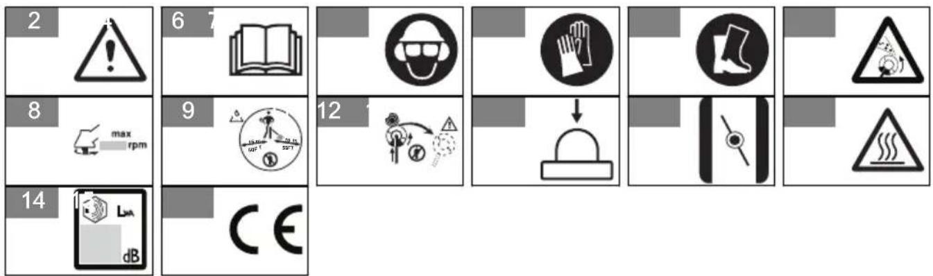
Symbols on the product
WARNING! This product is dangerous. Injury or death can occur to the operator or bystanders if the product is not used carefully and correctly. To prevent injury to the operator or bystanders, read and obey all safety instructions in the operator's manual.
(Fig. 2)
Please read the operator's manual carefully and make sure that you understand the instructions before use. (Fig. 3)
Use a protective helmet in locations where objects can fall on you. Use approved hearing protection. Use approved eye protection.
(Fig. 4)
(Fig. 5) Use approved protective gloves.
(Fig. 6) Use heavy-duty slip-resistant boots.
The product can cause objects to eject, (Fig. 7) which can cause injury.
(Fig. 8) Maximum speed of the output shaft.
Keep a minimum of 15 m (50 ft) distance to persons and animals during operation of the product.
(Fig. 9)
Risk of blade thrust if the cutting equipment touches an object that it does not immediately cut. The product can cut off body parts. Keep a minimum of 15 m (50 ft) distance to persons and animals during operation of the product.
(Fig. 10 )
(Fig. 11) Air purge bulb.
Choke: Set the choke control in the choke (Fig. 12) position.
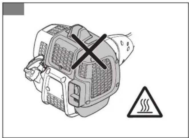
(Fig. 13) Keep all parts of your body away from the hot surfaces.
Noise emission to the environment refer to the European Community's Directive. The emission of the product is specified in the
(Fig. 14) Technical data chapter and on the label.
The product agrees with the applicable EC directives. (Fig. 15)
Note: Other symbols/decals on the product refer to certification requirements for other commercial areas.
Product liability
As referred to in the product liability laws, we are not liable for damages that our product causes if:
• the product is incorrectly repaired.
- the product is repaired with parts that are not from the manufacturer or not approved by the manufacturer.
- the product has an accessory that is not from the manufacturer or not approved by the manufacturer.
- the product is not repaired at an approved service center or by an approved authority.
SAFETY
Safety definitions
The definitions below give the level of severity for each signal word.

WARNING: Injury to persons.

CAUTION: Damage to the product.
Note: This information makes the product easier to use.
General safety instructions
- Use the product correctly. Injury or death is a possible result of incorrect use. Only use the product for the tasks found in this manual. Do not use the product for other tasks.
- Obey the instructions in this manual. Obey the safety symbols and the safety instructions. If the operator does not obey the instructions and the symbols, injury, damage or death is a possible result.
- Do not discard this manual. Use the instructions to assemble, to operate and to keep your product in good condition. Use the instructions for correct installation of attachments and accessories. Only use approved attachments and accessories.
- Do not use a damaged product. Obey the maintenance schedule. Only do the maintenance work that you find an instruction about in this manual. An approved service center must do all other maintenance work.
-
This manual cannot include all situations that can occur when you use the product. Be careful and use your common sense. Do not operate the product or do maintenance to the product if you are not sure about of the situation. Speak to a product expert, your dealer, service agent or approved service center for information.
-
Disconnect the spark plug cable before you assemble the product, put the product into storage or do maintenance.
- Do not use the product if it is changed from its initial specification. Do not change a part of the product without approval from the manufacturer. Only use parts that are approved by the manufacturer. Injury or death is a possible result of incorrect maintenance.
- Do not breathe in the fumes from the engine. Long term inhalation of the engine's exhaust fumes is a health risk.
- Do not start the product indoors or near flammable material. The exhaust fumes are hot and can contain a spark which can start a fire. Not sufficient airflow can cause injury or death because of asphyxiation or carbon monoxide.
- When you use this product the engine makes an electromagnetic field. The electromagnetic field can cause damage to medical implants. Speak to your physician and medical implant manufacturer before you operate the product.
- Do not let a child operate the product. Do not let a person, without knowledge of the instructions operate the product.
- Make sure that you always monitor a person, with decreased physical capacity or mental capacity, that uses the product. A responsible adult must be there at all times.
- Lock the product in an area that children and unapproved persons cannot access.
- The product can eject objects and cause injuries. Obey the safety instructions to decrease the risk of injury or death.
- Do not go away from the product when the engine is on.
- The operator of the product is responsible if an accident occurs.
- Make sure that parts are not damaged before you use the product.
- Make sure that you are at a minimum 15 m (50 ft) away from other persons or animals before you use
the product. Make sure that a person in adjacent area knows that you will use the product.
- Refer to national or local laws. They can prevent or decrease the operation of the product in some conditions.
- Do not use the product if you are fatigued or infused by alcohol, drugs or medicine. They can have effects on your vision, alertness, coordination or judgment.
Safety instructions for operation
- Make sure the product is fully assembled before you use it.
- Before a start, move the product 3 m (10 ft) away from the position where you filled the fuel tank. Put the product on a flat surface. Make sure that the cutting attachment does not touch the ground or other objects.
- The product can cause objects to eject, which can cause damage to the eyes. Always use an approved eye protection when you operate the product.
- Be careful, a child can come near the product without your knowledge during operation.
- Do not operate the product if there are persons in the work area. Stop the product if a person goes into the work area.
- Make sure that you are always in control of the product.
- Do not use the product if you cannot receive aid if an accident occurs. Always make sure others know you will operate the product before you start to operate the product.
- Do not turn with the product before you make sure that no persons or animals are in the safety area.
- Remove all unwanted materials from the work area before you start. If the cutting attachment hits an object, the object can eject and cause injury or damage. Unwanted material can wind around the cutting attachment and cause damage.
- Do not use the product in bad weather (fog, rain, strong winds, risk of lightning or other weather conditions.). Dangerous conditions (such as slippery surfaces) can occur because of bad weather.
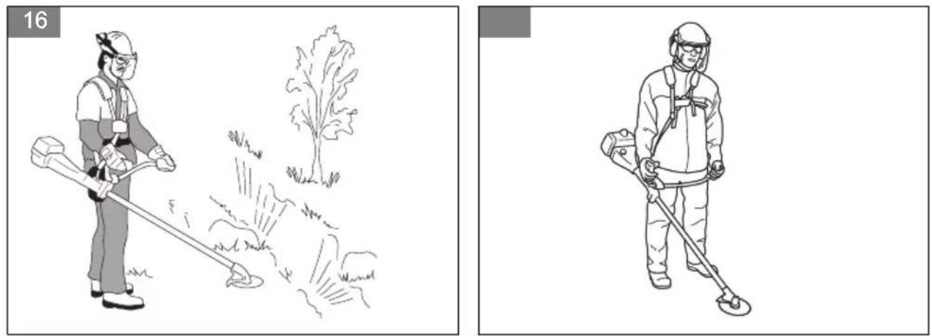
- Make sure that you can move freely and work in a stable position.
(Fig. 16)
Personal protective equipment
• Always use correct personal protective equipment when you operate the product. The personal protective equipment does not erase the risk of injury. The personal protective equipment decreases the grade of injury if an accident occurs.
• Always use an approved eye protection while you operate the product.
- Do not operate the product with bare feet or with open shoes. Always use heavy-duty slip-resistant boots.
- Use heavy, long pants.
- If it is necessary, use approved protective gloves.
- Use a helmet if it is possible that objects fall on your head.
• Always use approved ear protection while you operate the product. Noise for a long period can cause noise-induced hearing loss.
- Make sure that you have a first aid kit near.
Protective devices on the product
- Make sure that you regularly do the maintenance to the product.
• The life of the product increases.
• The risk of accidents decreases.
Let an approved dealer or an approved service center regularly examine the product to do adjustments or repairs.
- Do not use a product with damaged protective equipment. If the product is damaged, speak to an approved service center.
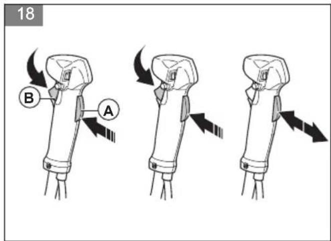
Throttle trigger lockout
The throttle trigger lockout locks the throttle trigger. (Fig. 18)
Push the throttle trigger lockout (A) to release the throttle trigger (B). When you release the handle, the throttle trigger lockout and the throttle trigger go back to their initial positions.
- Make sure that the throttle trigger (B) is locked at idle when you release the throttle trigger lockout (A).
- Push the throttle trigger lockout (A) and make sure that it goes back to its initial position when you release it.
- Push the throttle trigger (B) and make sure that it goes back to its initial position when you release it.
Start the engine, and then apply full throttle. Release the throttle trigger and examine if the cutting attachment stops. If the cutting attachment turns with the throttle in the idle position, examine the idle adjustment screw of the carburetor.
Stop switch
Start the engine. Make sure that the engine stops when you move the stop switch to the stop position.
(Fig. 19)
Cutting attachment guard
The cutting attachment guard prevents a loose object to eject in the direction of the operator. Examine the cutting attachment guard for damage and replace if it is damaged. Only use the approved guard for the cutting attachment.
(Fig. 20)
(Fig. 21)
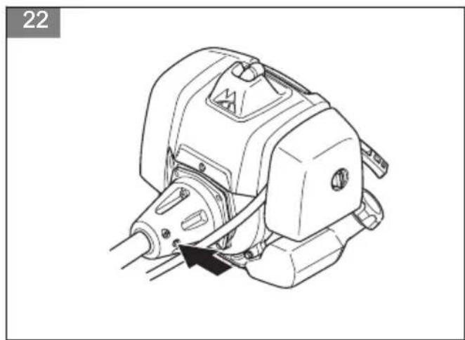
Vibration damping system

WARNING: Overexposure to vibration can lead to circulatory damage or nerve damage in people who have impaired circulation. Contact your doctor if you experience symptoms of overexposure to vibration. Such symptoms include numbness, loss of feeling, tingling, pricking, pain, loss of strength, changes in skin color or condition. These symptoms normally appear in the fingers, hands or wrists. These symptoms may be increased in cold temperatures.
- Your product has a vibration damping system to reduce vibration and make operation easier.
- Incorrect wound trimmer line or blunt or incorrect cutting attachment increases the level of vibration.
(Fig. 22)
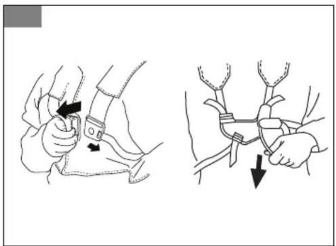
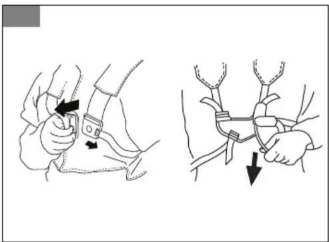
Harness release function

WARNING: Do not use the harness if the release function is defective. Make sure that the harness release function operates correctly when you adjust the product.
The harness release function is at the front of the product. The harness straps must always stay at the correct position.
(Fig. 23)
In an emergency, the harness release function helps you to safely release from the product.
Muffler
- Do not use an engine with a damaged muffler. A damaged muffler increases the noise level and the risk of fire. Keep a fire extinguisher near.
- Examine regularly that the muffler is attached to the product.
-
Do not touch the engine or the muffler when then engine is on. Do not touch the engine or the muffler for a while after the engine stops. Hot surfaces can cause injuries.
-
A hot muffler can cause a fire. Be careful, if you use the product near flammable liquids or fumes.
- Do not touch the parts in the muffler, if the muffler is damaged. The parts can contain some carcinogenic chemicals.
(Fig. 24)
Cutting equipment
Choose and maintain the cutting equipment to:
- Obtain maximum cutting performance.
- Increase life span of the cutting equipment.
- Follow the checking, maintenance and service instructions for the muffler.
- Always use the recommended guard for the cutting equipment. See Technical data.

WARNING: Only use cutting attachments with the guards we recommend! See the chapter on Technical data. Refer to the instructions for the cutting attachment to check the correct way to load the trimmer line and the correct trimmer line diameter.

WARNING: A faulty cutting attachment may increase the risk of accidents.

WARNING: Always stop the engine before doing any work on the cutting attachment. This continues to rotate even after the throttle has been released. Ensure that the cutting attachment has stopped completely and disconnect the spark plug cap before you start to work on it.
Cutting equipment
- Use the saw blade to cut fibrous types of wood. (Fig. 25)
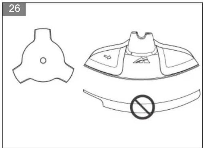
- Use the blades and grass knives to cut coarse grass. (Fig. 26)
- Use the trimmer head to trim grass.
(Fig. 27)
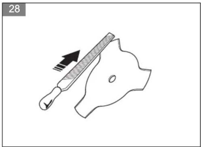
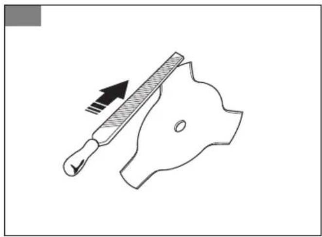
- An incorrectly sharpened or damaged blade increases the risk of accidents. Keep the teeth of the blade correctly sharpened. Follow the instructions and use the recommended file gauge.
(Fig. 28)
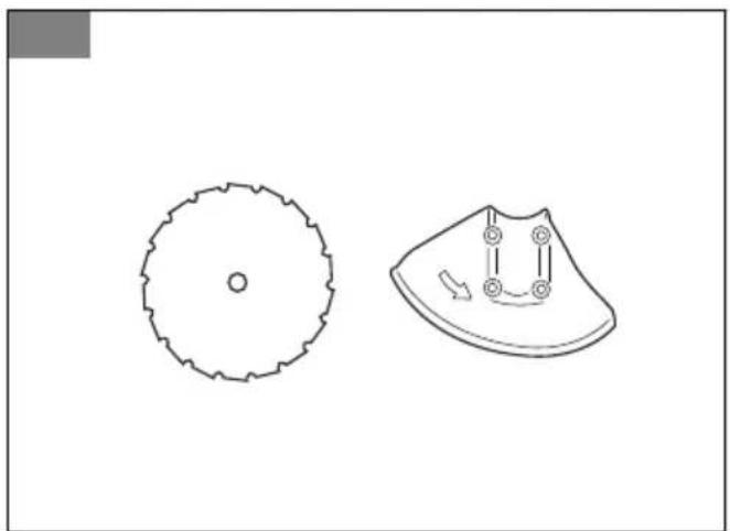
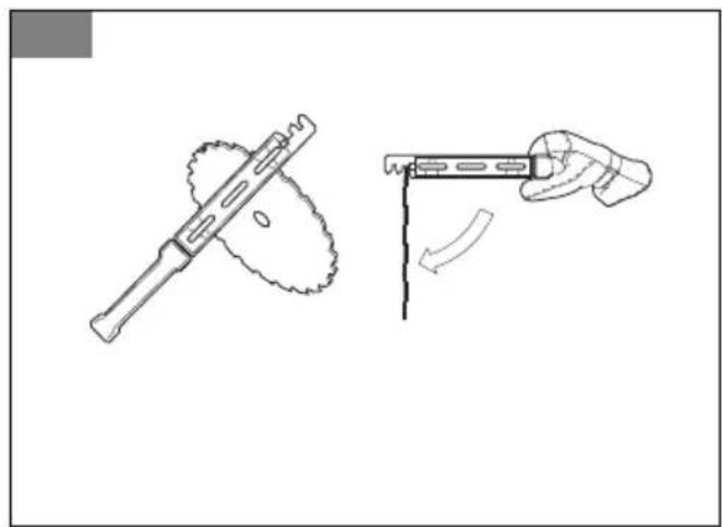
- An incorrectly set saw blade increases the risk of jamming and blade thrust. This can damage the saw blade. Keep the correct setting on the saw blade. Follow the instructions and use the recommended setting tool.
(Fig. 29)
- Check the cutting attachment for damage or cracks. Replace a damaged cutting attachment.
- Only use cutting attachments with recommended guards. See ACCESSORIES on page 22.
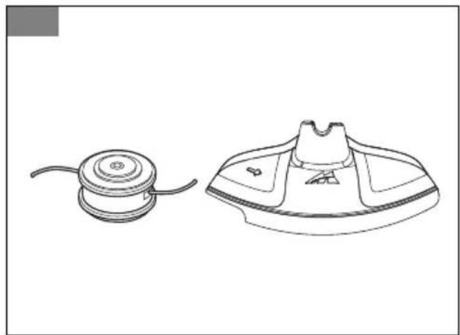
Trimmer head

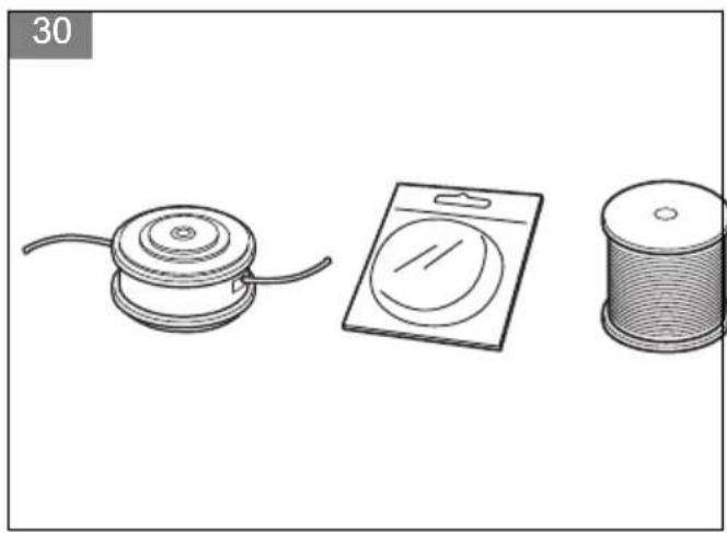
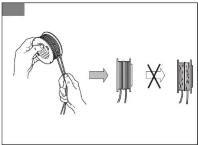
WARNING: Always make sure the trimmer line is wound tightly and evenly around the drum to prevent harmful vibration.
(Fig. 30)
- Only use recommended trimmer heads and trimmer lines.
- Only use recommended cutting attachments.
- Smaller machines requires small trimmer heads and vice versa.
- The length of the trimmer line is important. A longer trimmer line requires greater engine power than a shorter trimmer line of the same diameter.
- Make sure that the cutter on the trimmer guard is intact. This cuts the trimmer line to the correct length.
- Soak the trimmer line in water for a couple of days before use to increase the life length.
Blades
- Use the product with an approved blade. Do not use a blade without proper installation of all required parts. Make sure that the installation is done correctly and that the proper parts are used. Improper installation may cause the blade to fly off and seriously injure the operator or bystanders.
- Wear protective gloves when you handle the blade or do maintenance.
- Use head protection when you operate a product with a blade.
- A blade can cause injury when it spins after the engine is stopped or the throttle trigger is released. Make sure that the blade has completely stopped rotating before maintenance.
- Stop the engine before you do work on the cutting attachment. Make sure the cutting attachment fully stops. Disconnect the lead from the spark plug.
- Keep the teeth of the blade correctly sharpened. (Fig. 31)
- Do not use a damaged cutting attachment.
- Attach the transport guard to the blade when you transport or store the product.
Blade thrust
- A blade thrust is a sudden movement of the product to the side, forward or rearward. A blade thrust occurs when the grass blade or saw blade hits an object that cannot be cut. In areas where it is not easy to see the material being cut the risk of blade thrust increases.
- When a blade thrust occurs, there is a risk that the product or the operator moves out of position. A
blade that moves can hit bystanders and there is a risk of injuries.
- If a blade is bent, has cracks, is broken or damaged, discard the blade.
- Use a sharp blade. The risk of blade thrust increases when a blade is not sharp.
Fuel safety
- Do not start the product if there is fuel or engine oil on the product. Remove the unwanted fuel/oil and let the product dry. Remove unwanted fuel from the product.
- If you spill fuel on your clothing, change clothing immediately.
- Do not get fuel on your body, it can cause injury. If you get fuel on your body, use a soap and water to remove the fuel.
- Do not start the engine if you spill oil or fuel on the product or on your body.
- Do not start the product if the engine has a leak. Examine the engine for leaks regularly.
- Be careful with fuel. Fuel is flammable and the fumes are explosive and can cause injuries or death.
- Do not breathe in the fuel fumes, it can cause injury. Make sure that there is a sufficient airflow.
- Do not smoke near the fuel or the engine.
- Do not put warm objects near the fuel or the engine.
- Do not add the fuel when the engine is on.
- Make sure that the engine is cool before you refuel.
- Before you refuel, open the fuel tank cap slowly and release the pressure carefully.
- Do not add fuel to the engine in an indoor area. Not sufficient airflow can cause injury or death because of asphyxiation or carbon monoxide.
- Tighten the fuel tank cap carefully or a fire can occur.
- Move the product at a minimum of 3 m (10 ft) from the position where you filled the tank before a start.
- Do not put too much fuel in the fuel tank.
- Make sure that a leak cannot occur when you move the product or fuel container.
- Do not put the product or a fuel container where there is an open flame, spark or pilot light. Make sure that the storage area does not contain an open flame.
- Only use approved containers when you move the fuel or put the fuel into storage.
- Empty the fuel tank before long-term storage. Obey the local law on where to dispose fuel.
- Clean the product before long-term storage.
- Remove the spark plug cable before you put the product into storage to make sure that the engine does not start accidentally.
Safety instructions for maintenance
- If you cannot adjust the idle speed to make the cutting attachment stop, speak to your service
ASSEMBLY

WARNING: Read the safety chapter before you assemble the product.
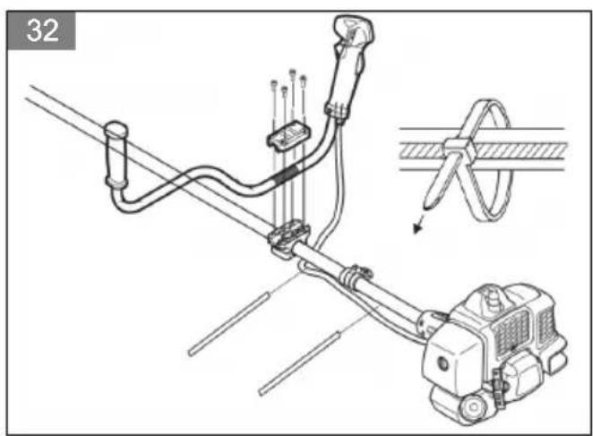
To install the handlebar
- Attach the handlebar onto the mounting bracket as shown. (Fig. 32)
- Attach the cable to the shaft with the zip ties.
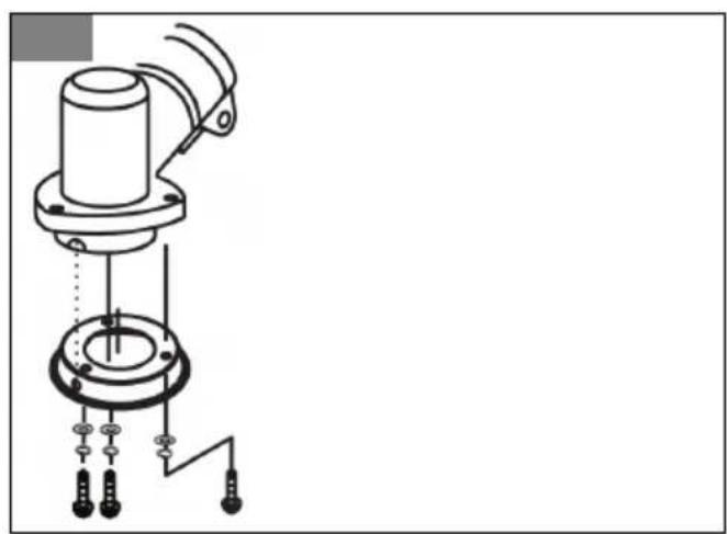
To install the protective guard
- Attach the protective guard onto the shaft as shown. (Fig. 33)
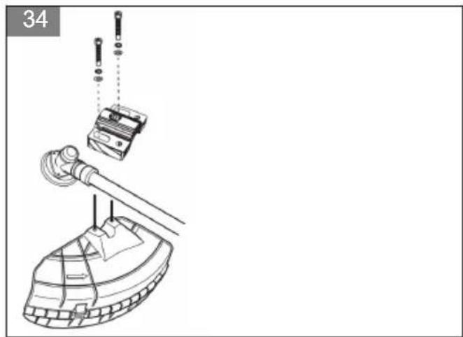
To attach the cutting attachment guard for the trimmer head and grass blade
- Attach the cutting attachment guard onto the shaft as shown. (Fig. 34)
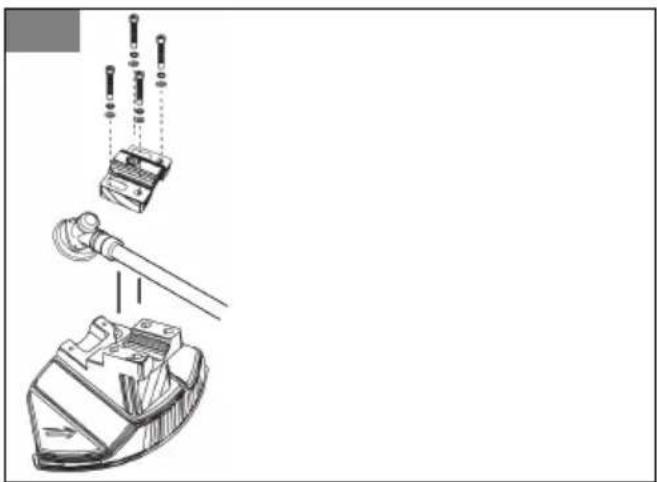
To attach the cutting attachment guard for the saw blade
- Attach the cutting attachment guard onto the shaft as shown. (Fig. 35)
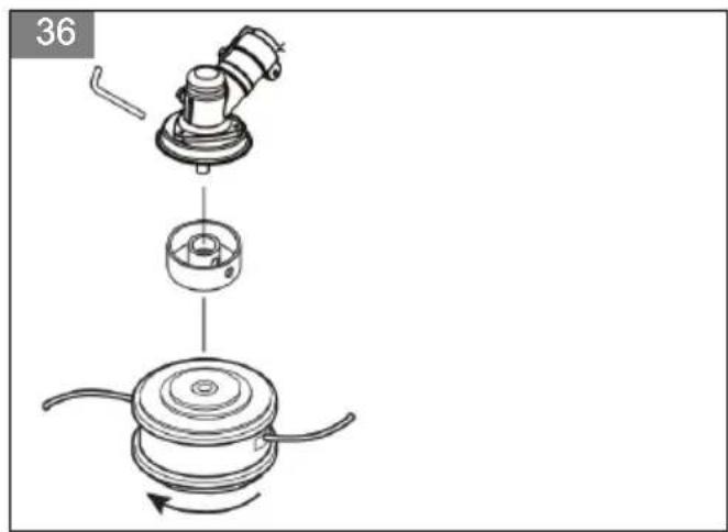
To install the trimmer head
- Attach the drive disc on the output shaft.
- Turn the output shaft until one of the holes in the drive disc aligns with the related hole in the gear housing.
- Put the hex wrench in the hole to lock the shaft.
- Turn the trimmer head onto the shaft. (Fig. 36)
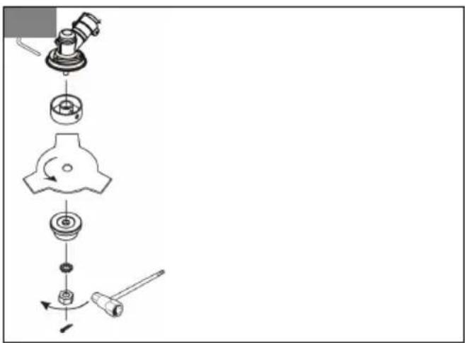
To install the grass blade
- Attach the drive disc on the output shaft.
- Turn the output shaft until one of the holes in the drive disc aligns with the related hole in the gear housing.
- Put the hex wrench in the hole to lock the shaft.
- Install the blade on the shaft.
- Attach the support flange, washer and nut on the output shaft.
-
Tighten the nut fully with the socket wrench.
-
Install the retainer pin in the nut. (Fig. 37)
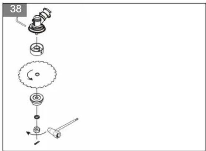
To install the saw blade
- Attach the drive disc on the output shaft.
- Turn the output shaft until one of the holes in the drive disc aligns with the related hole in the gear housing.
- Put the hex wrench in the hole to lock the shaft.
- Install the blade on the shaft. Make sure the cutters point in the correct direction.
- Attach the support flange, washer and nut on the output shaft.
- Tighten the nut fully with the socket wrench.
- Install the retainer pin in the nut. (Fig. 38)
To adjust the harness

WARNING: The product must always be hooked securely to the harness. Never use a harness with a defective quick release.

WARNING: Use the harness release function if you must release from the product and the harness in an emergency situation.
(Fig. 39)
- Put on the harness.
- Adjust the harness for the best work position.
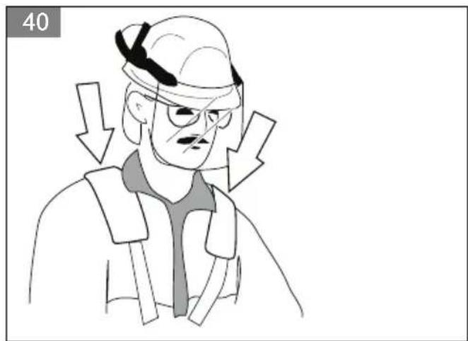
- Adjust the side straps until the weight is equally distributed across your shoulders.(Fig. 40)
- Adjust the harness until the cutting attachment is parallel to the ground.
- Let the cutting attachment stay lightly on the ground. And then adjust the harness clamp to balance the product correctly.
Note: If you use a grass blade, it must balance approximately 10 cm (4 in) above the ground to keep the grass blade from stones and so on.
To attach the transport guard
- Attach the transport guard on the blade as shown in the illustration.(Fig. 41)
OPERATION

WARNING: Read and understand the safety chapter before you operate the product.
Fuel
To use fuel

CAUTION: This product has a two-cycle engine. Use a mixture of gasoline and two-cycle engine oil. Make sure to use the correct quantity of oil in the mixture.
Incorrect ratio of gasoline and oil can cause damage to the engine.
Gasoline

CAUTION: Do not use gasoline with an octane number less than 90 RON (87 AKI). This can cause damage to the product.

CAUTION: Do not use gasoline with more than 10% ethanol concentration (E10). This can cause damage to the product.
• Always use new unleaded gasoline with a minimum octane number of 90 RON (87 AKI) and with less than 10% ethanol concentration (E10).
- Use gasoline with a higher octane number if you frequently use the product at continuously high engine speed.
Two-cycle engine oil
- Use only high quality two-cycle engine oil. Use only an air cooled engine oil.
- Do not use other types of oil.
• Mixture ratio 50:1 (2%)
| Petrol, litre | Two-stroke oil, litre |
| 5 0.10 | |
| 10 0.20 | |
| 15 0.30 | |
| 20 0.40 | |
To make the fuel mixture
Note: Always use a clean fuel container when you mix the fuel.
Note: Do not make more than 30 days quantity of fuel mixture.
- Add half of the gasoline quantity.
- Add the full quantity of oil.
- Shake the fuel mixture to mix the contents.
- Add the remaining gasoline quantity.
- Shake the fuel mixture to mix the contents.
- Fill the fuel tank.
To add fuel
- Always use a fuel container with an antispill valve.
- If there is some fuel on the container, remove the unwanted fuel and let the container dry.
- Make sure that the area near the fuel tank cap is clean.
- Shake the fuel container before you add the fuel mixture to the fuel tank.
To start and stop
To examine the product before start
- Examine the product for missing, damaged, loose or worn parts.
- Examine the nuts, screws and bolts.
- Examine the blades.
- Examine the air filter.
- Examine the throttle trigger lockout and the throttle control.
- Examine the stop switch.
- Examine the product for fuel leaks.
To start a cold engine
- Set the stop switch to the start position.
- Push the start throttle button.
- Press the air purge 10 times. The bulb must not be completely filled.(Fig. 42)
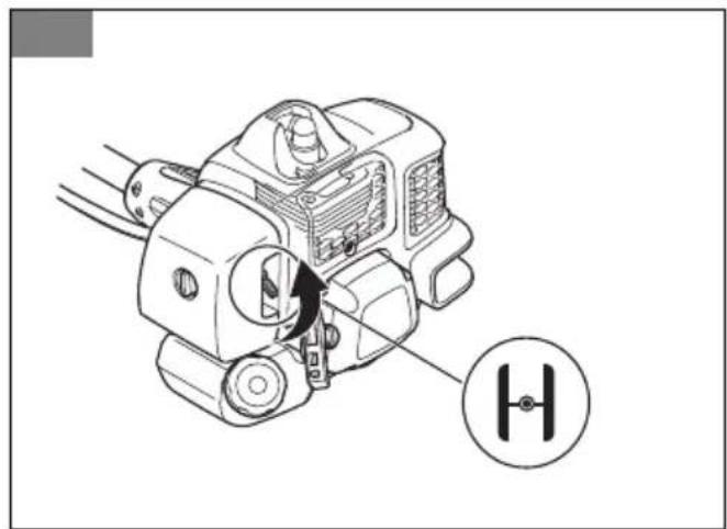
- Set the choke control in the choke position.(Fig. 43)
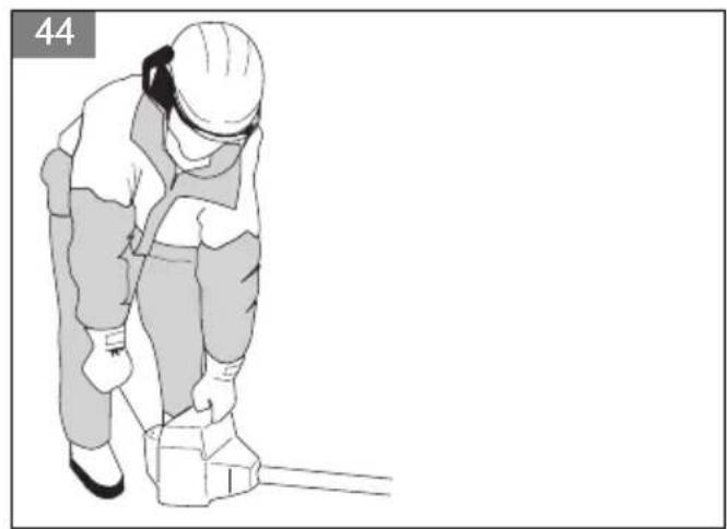
- Hold the body of the machine on the ground with the left hand. Pull out the cord slowly with your right hand until you fell some resistance. Pull the cord quickly and powerfully. Repeat until the engine starts.(Fig. 44)

WARNING: Use the starter handle. Do not twist the starter cord around your hand.

CAUTION: Do not pull the starter cord all the way out. Do not let go of the starter handle when the cord is fully extended.
-
Return the choke control to the run position.
-
Let the engine run for 10 seconds.
-
Pull the throttle trigger lightly to run at low speed for 60 seconds.

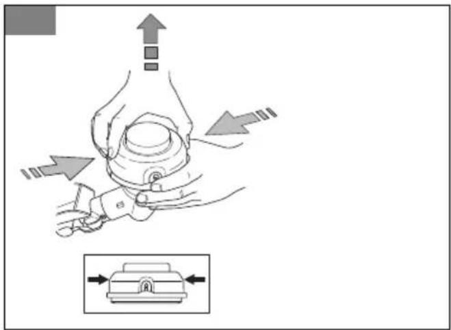
WARNING: Do not touch the cover.
Contact can result in burns to the skin.

WARNING: Do not touch the cover. If the spark plug is damaged contact can
(Fig. 45)
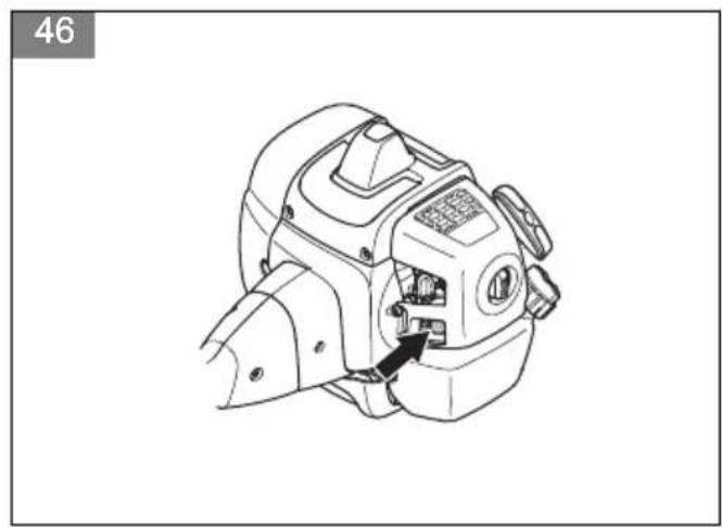
To start a warm engine
- Set the stop switch to the start position.
- Press the air purge 10 times. The bulb must not be completely filled.(Fig. 46)
- Return the choke control to the run position.
- Pull the cord quickly and powerfully. Repeat until the engine starts.
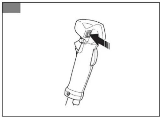
To stop
- Switch off the ignition to stop the engine.(Fig. 47)
To operate the grass trimmer

CAUTION: Make sure that you slow the engine to idle speed after each operation. A long period at full throttle without a load on the engine can cause damage to the engine.
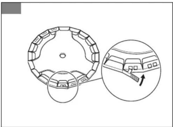
Note: Clean the cover of the trimmer head when you attach a new trimmer line to prevent vibrations. Examine other parts of the trimmer head and clean if it is necessary.
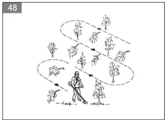
General work instructions

WARNING: Be careful when you cut a tree that is in tension. It can spring back to its normal position before or after the cut and hit you or the product, and cause injury.
- Clear an open space at one end of the work area, and start the work from there.
- Move in a regular pattern across the work area.(Fig. 48)
- Move the product fully to the left and right, to clear a width of 4–5 m (13-16 ft) on each turn.
- Clear a length of 75 m (250 ft) before you turn and go back. Move the fuel can along with you as you continue.
- Move in a direction where you do not go across ditches and obstacles more than necessary.
- Move in a direction where the wind makes the cut vegetation fall in the cleared area.(Fig. 49)
- Move along slopes, not up and down.
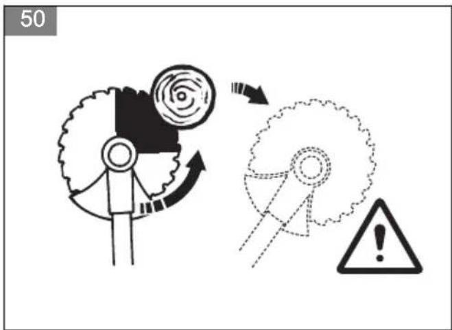
To forestry clear with a saw blade
- The risk of blade thrust increases with increasing stem size. therefore avoid cutting with the area of the blade between 12 o'clock and 3 o'clock.(Fig. 50)
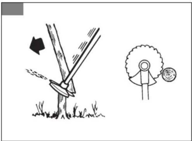
- To fell to the left, the bottom of the tree should be pushed to the right. Tilt the blade and bring it diagonally down to the right, exerting firm pressure.
At the same time push the stem using the blade guard. Cut with the area of the blade between 3 o'clock and 5 o'clock. Apply full throttle before advancing the blade. (Fig. 51)
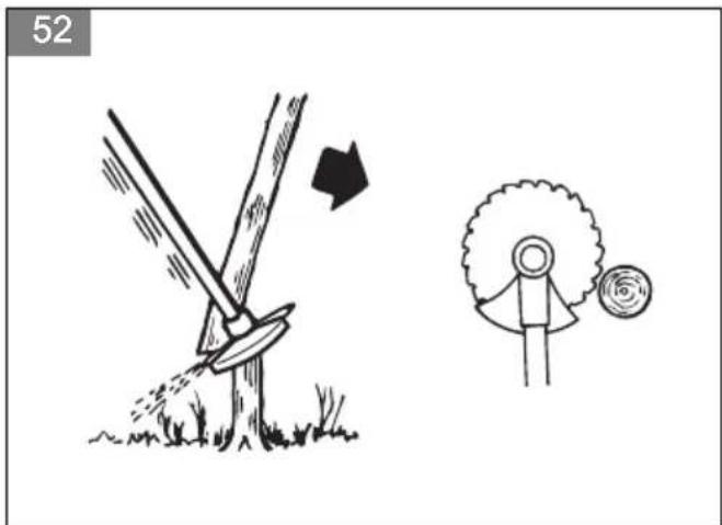
- To fell to the right, the bottom of the tree should be pushed to the left. Tilt the blade and bring it diagonally up to the right. Cut with the areas of the blade between 3 o'clock and 5 o'clock so that the directions of rotations of the blade pushes the bottom of the tree to the left.(Fig. 52)
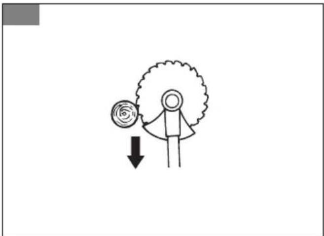
- To fell a tree forwards, the bottom of the tree should be pulled backwards. Pull the blade backwards with a quick, firm movement. (Fig. 53)
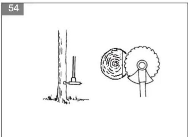
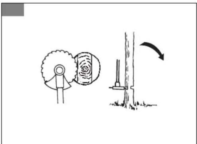
- Large stems must be cut from two sides. First determine which direction the stem will fall. Make the first cut on the felling side. Then finish cutting the stem from the other side. Adjust the cutting pressure to match the size of the stem and the hadness of the wood. Small stems require more pressure, while large stems require less pressure. (Fig. 54) (Fig. 55)
- If the stems are tightly packed, adapt your walking pace to suit.
- If the blade jams in a stem, never jerk the machine free. If you do this the blade, bevel gear, shaft or handlebar may be damaged. Release the handles, grip the shaft with both hands and gently pull the machine free.
Brush cutting with a saw blade
To fell to the left, push the bottom of the tree to the right.
- Cut down thin trees and brush.
- Move the product from side to side.
- Cut many trees in one movement.
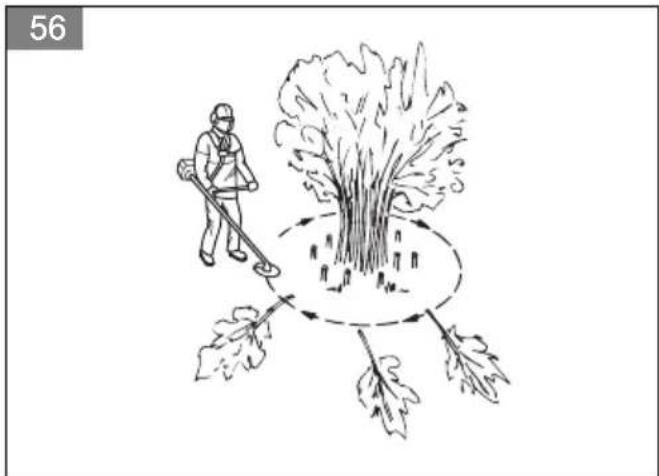
- For groups of thin trees:(Fig. 56)
a) Cut the outer trees high up.
b) Cut the outer trees to the correct height.
c) Cut from the center. If you cannot get access to the center, cut the outer trees high up and let them fall. This decreases the risk that the saw blade becomes blocked.
To clear grass with a grass blade
- Grass blades and grass cutters must not be used on woody stems.
- A grass blade is used for all types of tall or coarse grass.
- The grass is cut down with a sideways, swinging movement, where the movement from right-to-left is the clearing stoke and the movement from left-to-right is the return stoke. Let the left-hand side of the blade (between 8 and 12 o'clock) do the cutting.
-
if the blade is angled to the left when clearing grass, the grass will collect in a line, which makes it easier to collect, e.g. by raking.
-
Try to work rhythmically. Stand firmly with your feet apart. Move forward after the return stoke and stand firmly again.
- Let the support cup rest lightly against the ground. It is used to protect the blade from hitting the ground.
- Reduce the risk of material wrapping around the blade by always work at full throttle and avoid the previously cut material during the return stoke.
- Stop the engine, unclip the harness and place the machine on the ground before you start to collect the cut material.
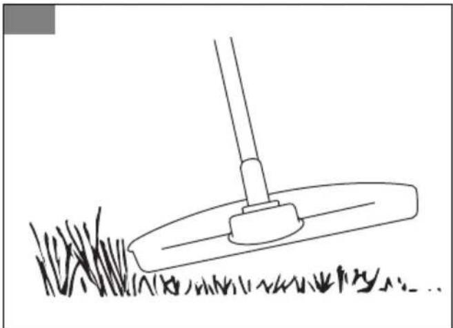
To trim the grass
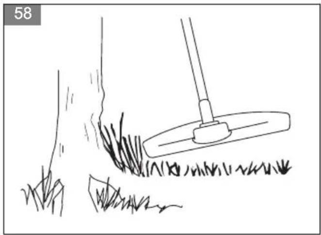
- Hold the trimmer head immediately above the ground at an angle.(Fig. 57) Do not push the grass trimmer line into the grass.
- Decrease the length of the grass trimmer line by 10-12 cm (4-4.75 in) and decrease engine speed to decrease the risk of damage to plants.
- Use 80 % throttle when you cut grass near objects.
(Fig. 58)
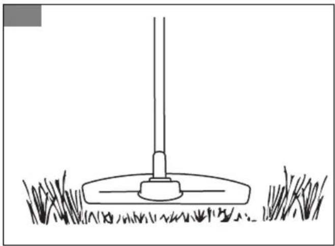
To cut the grass
- Make sure that the grass trimmer line is parallel to the ground when you cut.(Fig. 59)
- Do not push the trimmer head to the ground. The ground and the product can be damaged.
-
Do not let the trimmer head touch the ground continuously, it can cause damage to the trimmer head.
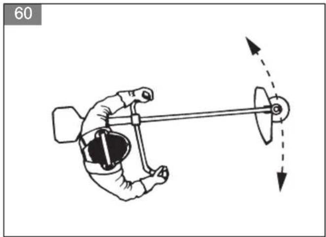
-
Use full throttle when you move the product from side to side to cut grass. (Fig. 60) Make sure that the grass trimmer line is parallel to the ground.
To sweep the grass
The airflow from the rotating trimmer line can be used to remove cut grass from an area.
- Hold the trimmer head and its trimmer line parallel to the ground and above the ground.
- Apply full throttle.
- Move the trimmer head from side to side and sweep the grass.

WARNING: Clean the trimmer head cover each time you assemble new trimmer line to prevent unbalance and vibrations in the handles. Also do a check of the other parts of the trimmer head and clean it if necessary.
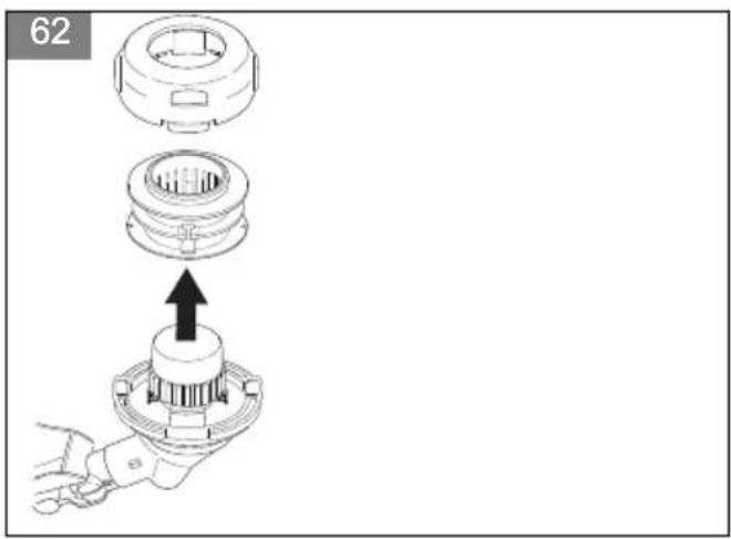
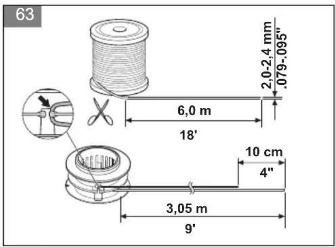
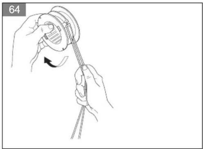
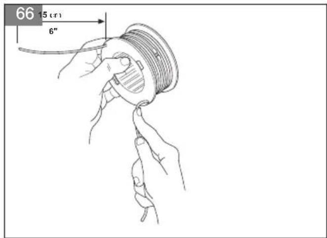
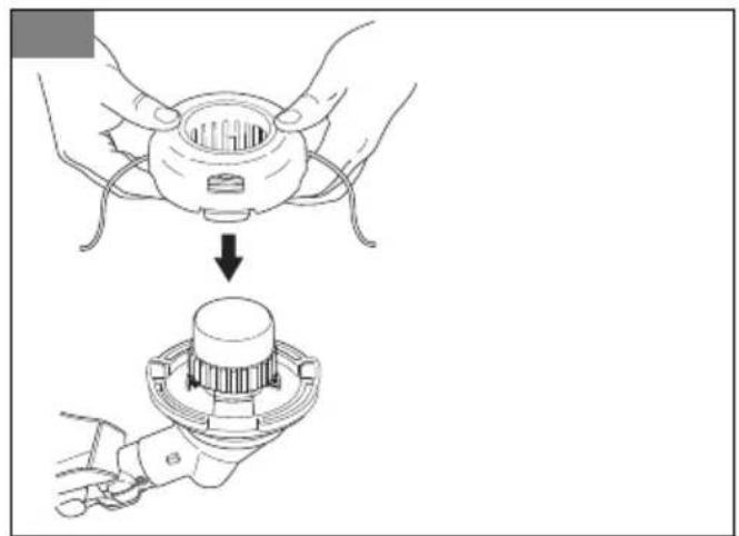
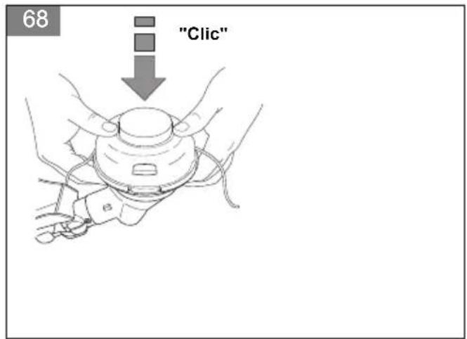
To replace the trimmer line
(Fig. 61)
(Fig. 62)
(Fig. 63)
(Fig. 64)
(Fig. 65)
(Fig. 66)
(Fig. 67)
(Fig. 68)
MAINTENANCE

WARNING: Read and understand the safety chapter before you clean, repair or do maintenance on the product.
Maintenance schedule
Make sure that you obey the maintenance schedule.
The intervals are calculated from daily use of the product. The intervals are different if you do not use the product each day. Only do the maintenance work that is found in this manual. Speak to an approved service center about other maintenance work not found in this manual.
Daily maintenance
Weekly maintenance
- Examine the starter rope handle and the starter rope.
- Examine the bevel gear grease.
- Clean the outside of the carburettor and its adjacent areast.
- Clean the outside of the spark plug. Remove it and check the electrode gap. Adjust the gap or replace the spark plug. Check that the spark plug is fitted with a suppressor.
Monthly maintenance
To adjust the carburetor
The basic carburetor settings are adjusted during testing at the factory. Adjustment must be carried out by a trained technician.
To do a check of the muffler

WARNING: Do not use a product that has a defective muffler. Always replace a defective muffler.

WARNING: Mufflers with catalytic converters get very hot during operation. Risk of burn or fire.

WARNING: The muffler decrease the noise level and point the exhaust gases from the operator. The exhaust gases are hot and can contain sparks. Risk of fire.

CAUTION: The spark arrestor spark arrester screen must be replaced if it is damaged. Do not use a product if the spark arrestor spark arrester screen on the muffler is missing or defective.

CAUTION: If the spark arrestor spark arrester screen is blocked the product will too hot. This will cause damage to the cylinder and piston.
- Make sure that the muffler is not damaged.
- Make sure that the muffler is correctly attached to the product.
- Some mufflers have a special spark arrestor spark arrester screen. Clean the spark arrestor spark arrester screen minimum one a week if your product has this type of muffler. Use a wire brush.(Fig. 69)
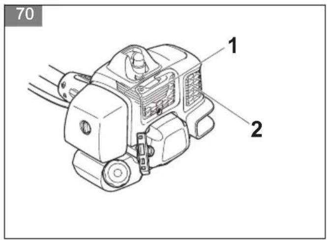
To clean/do maintenance on the cooling system
This product has a cooling system. A dirty or blocked cooling system can make the product too hot which can damage to the piston and cylinder. Check and clean the cooling system with a brush one time each week or more frequently in demanding conditions. The cooling system consists of cooling fins on the cylinder (1) and air intake (2).
(Fig. 70)
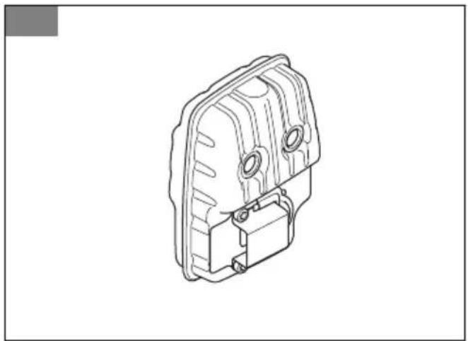
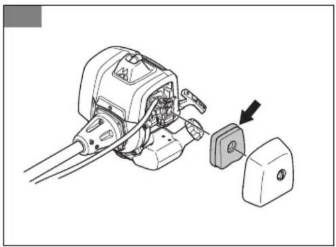
To clean the air filter
- Remove the air filter cover and remove the air filter. (Fig. 71)
- Clean the air filter with warm soap water. Make sure that the air filter is dry before you install it.
- Replace the air filter if it is too dirty to fully clean it. Always replace a damaged air filter.
- If your product has a foam air filter, apply air filter oil. Only apply air filter oil to a foam filter. Do not apply oil to a felt filter.
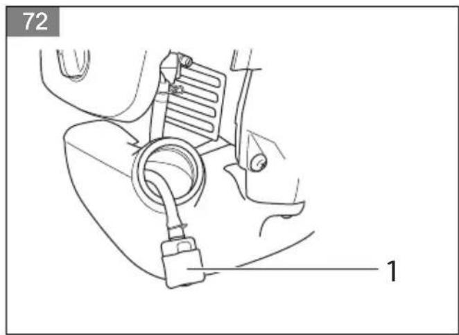
Fuel filter
When the engine runs short of fuel supply, make sure that the fuel tank cap and the fuel filter is not blocked. (Fig. 72)
To add grease to the bevel gear
Make sure that the bevel gear is filled 3/4 full with bevel gear grease.
(Fig. 73)
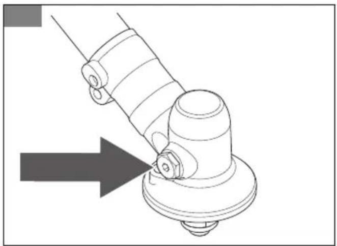
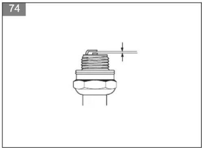
To examine the spark plug

CAUTION: Always use the recommended spark plug type. Incorrect spark plug type can cause damage to the product.
- Examine the spark plug if the engine is low on power, is not easy to start or does not operate correctly at idle speed.
- To decrease the risk of unwanted material on the spark plug electrodes, obey these instructions:
a) Make sure that the idle speed is correctly adjusted.
b) Make sure that the fuel mixture is correct.
c) Make sure that the air filter is clean.
- If the spark plug is dirty, clean it and make sure that the electrode gap is correct, see TECHNICAL DATA on page 21.(Fig. 74)
- Replace the spark plug if it is necessary.
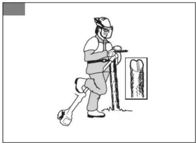
To sharpen the saw blade

WARNING: Stop the engine. Use protective gloves.
- To sharpen the blade correctly, refer to the instructions that come with the blade.
- Make sure that the product and blade has sufficient support when you sharpen it.(Fig. 75)
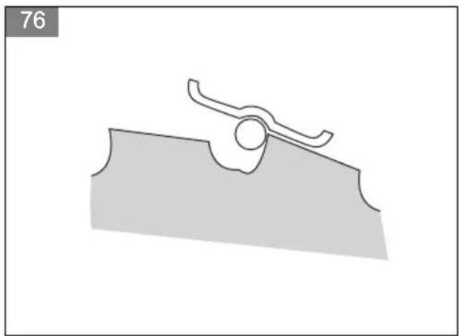
- Use a 5.5 mm (7/32 in) round file with a file holder. (Fig. 76)
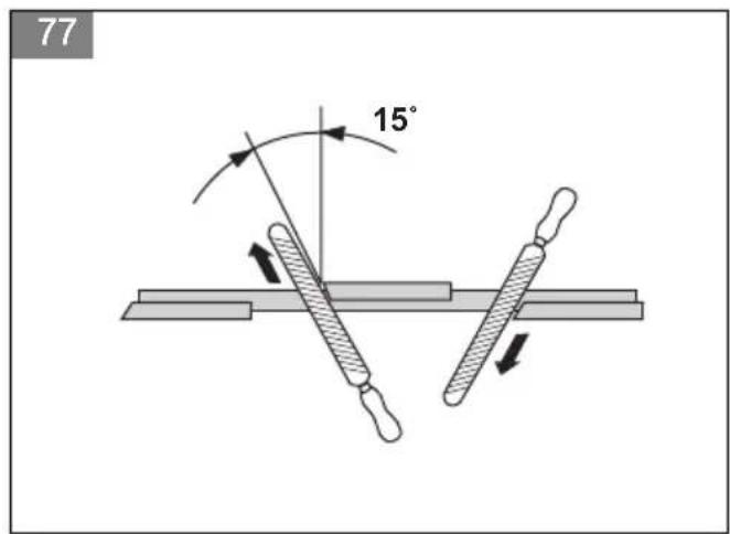
- Hold the file at an angle of 15^ .
- Sharpen one tooth of the saw blade to the right and the next tooth to the left, see the illustration.(Fig. 77)
Note: Sharpen the edges of the teeth with a flat file if the blade is heavily worn. Continue to sharpen with a round file.
- Sharpen all edges equally to keep the blade balanced.
- Adjust the blade set to 1 mm (0.04 in) with the recommended setting tool. Refer to the instructions that come with the blade.(Fig. 78)

WARNING: Always discard a blade that is damaged. Do not try to make a bent or twisted blade straight and use it again.
To sharpen grass cutters and grass blades
- Sharpen grass cutters and grass blades with a single-cut flat file.
- Sharpen all edges of the grass cutters and blades equally to keep the balance.(Fig. 79)
TRANSPORTATION AND STORAGE
TECHNICAL DATA
| unit B43BT | |
| Engine Specifications | | |
| Cylinder displacement cm | ^3 | 43 |
| Cylinder bore mm 40,0 | | |
| Stroke mm 34,0 | | |
| Idling speed rpm 2700 - 3300 | | |
| Maximum speed rpm 10000 | | |
| Speed of output shaft rpm 7000 | | |
| Maximum engine output kW/rpm 1,25/7000 | | |
| Spark plug QCJ-8Y | | |
| Electrode gap mm 0,65 | | |
| Fuel tank capacity litre 0,8 | | |
| Noise and Vibration Data | | |
| Equivalent vibration level (ahv, eq), equipped with grass blade, left/right handle - see note 1 | m/s^2 | 4,6/4,3 |
| Equivalent vibration level (ahv, eq) equipped with trimmer head, left/right handle - see note 1 | m/s^2 | 4,2/4,5 |
| Equivalent vibration level (ahv, eq) equipped with saw blade left/right handle - see note 1 | m/s^2 | 4,4/4,2 |
| Sound power level, guaranteed ( L_WA ) - see note 2 | dB(A) 118 | |
| Sound power level, measured - see note 2 | dB(A) 110 | |
| Sound pressure level at operator's ear, equipped with grass blade - see note 3 | dB(A) 96,7 | |
| Sound pressure level at operator's ear, equipped with trimmer head - see note 3 | dB(A) 95,4 | |
| Sound pressure level at operator's ear, equipped with saw blade - see note 3 | dB(A) 96,1 | |
| Product Dimensions | | |
| Weight (excluding cutting equipment) kg 7,7 | | |
| Note 1: Reported data for equivalent vibration level has a typical statistical dispersion (standard deviation) of 1,5 m/s2. Note 2: Noise emissions in the environment measured as sound power (LWA) in conformity with EC directive 2000/14/ EC. Reported sound power level for the machine has been measured with the original cutting attachment that gives the highest level. The difference between guaranteed and measured sound power is that the guaranteed sound power also includes dispersion in the measurement result and the variations between different machines of the same model according to Directive 2000/14/EC. Note 3: Reported data for equivalent sound pressure level for the machine has a typical statistical dispersion (standard deviation) of 3 dB (A). |
ACCESSORIES
| B43BT |
| Approved accessories Type Cutting attachment guard | |
| Center hole in blades/cutters, ∅ 25,4 mm | | |
| Output shaft thread M12 | | |
| Grass blade/grass cutter Grass blade | 255-3 (∅ 255 3 teeth) 580 30 50-01 | |
| Saw blade Saw blade 255-40 (∅ 255 40 teeth) 592 83 81-28 | | |
| Trimmer head P35 580 30 50-01 | | |
| Support cup Fixed - | | |
Inhalt
EINLEITUNG....23
SICHERHEIT....24
MONTAGE....29
BETRIEB....30
WARTUNG.... 33
TRANSPORT OCH FÖRVARING
TEKNISET TIEDOT.... 138
LISÄVARUSTEET.... 139
JOHDANTO
Käyttöohjekirja
Afiar as lâminas e as cortadoras de relva
(Obr. 11) Balónik pumpy.
ACCESSORIES (Lisavarustus)
| B43BT |
| Heakskiidetud lisavarustus Tüüp Lõikepea kaitse | | |
| Terade/lõikurite keskmine ava, ∅ 25,4 mm | | |
| Keermestatud teratelg M12 | | |
| Rohutera/rohunuga Rohutera 255-3 (∅ 255, 3 hammast) 580 30 50-01 | | |
| Saetera Saetera 255-40 (∅ 255, 40 hammast) 592 83 81-28 | | |
| Trimmeripea P35 580 30 50-01 | | |
| Tugikuppel Kinnitatud - | | |
TURINYS
[VADAS....269
SAUGA....270
SURINKIMAS.... 274
NAUDOJIMAS.... 275
PRIEŽIŪRA....277
GABENIMAS IR LAIKYMAS....279
TECHNINIAI DUOMENYS....279
PRIEDAI....280
|VADAS
Naudojimo instrukcija
natural_image
Abstract black geometric logo with curved lines forming triangular shapes (no text or symbols)
McCULLOCH®
www.mcculloch.com
Original instructions
Originalanweisungen