SBC 646 F - Lawn mower STIGA - Free user manual and instructions
Find the device manual for free SBC 646 F STIGA in PDF.
User questions about SBC 646 F STIGA
0 question about this device. Answer the ones you know or ask your own.
Ask a new question about this device
Download the instructions for your Lawn mower in PDF format for free! Find your manual SBC 646 F - STIGA and take your electronic device back in hand. On this page are published all the documents necessary for the use of your device. SBC 646 F by STIGA.
USER MANUAL SBC 646 F STIGA
natural_image
Silhouette of a person reading a book inside a circle (no text or symbols)IT Decespugliatore a motore portatile manualmente MANUALE DI ISTRUZIONI
ATTENZIONE: prima di usare la macchina, leggere attentamente il presente libretto.
BG Преносим ръчен моторен храсторез УПЪТВАНЕ ЗА УПОТРЕБА
ВНИМАНИЕ: преди да използвате машината прочетете внимателно настоящата книжка.
BS Ručna motorna trimer kosilica
UPUTSTVO ZA UPOTREBU
PAŽNJA: prije nego što koristite ovu mašlnu, pažljivo pročitajte priručnik s uputama.
CS Ručně prénosný motorový křovinořez
NÁVOD K POUŽITÍ
UPOZORNĚNÍ: před použitím stroje si pozorně přečtěte tento návod k použití.
DA Bærbar, håndholdt motordreven buskrydder BRUGSANVISNING
ADVARSEL: læs instruktionsbogen omhyggeligt igennem, før du tager denne maskine i brug.
DE Motorbetriebener Freischneider GEBRAUCHSANWEISUNG
ACHTUNG: vor inbetriebnahme des Geräts die Gebrauchsanleitung aufmerksam lesen.
EL Φορητό χειροκατευθυνόμενο θαμνοκοπτικό βενζίνης
ΟΔΗΓΙΕΣ ΧΡΗΣΠΣ
ΠΡΟΣΟΧΗ: πριν χρησιμοποιησετε το μηχανημα, διαβαστε προσεκτικα το παρον εγχειριδιο.
EN Hand-held powered brushcutter OPERATOR'S MANUAL
WARNING: read thoroughly the instruction booklet before using the machine.
ES Desbrozadora de motor portátil manualmente MANUAL DE INSTRUCCIONES
ATENCIÓN: antes de utilizar la máquina, leer atentamente el presente manual.
ET Käeskantav mootoriga võsalõikur
KASUTUSJUHEND
TÄHELEPANU: enne masina kasutamist lugeda tähelepanelikult antud kasutusjuhendit.
FI Käsin kannateltava moottorikäyttöinen raivaussaha
KÄYTTÖOHJEET
VAROITUS: lue käyttöopas huolellisesti ennen koneen käyttöä.
FR Débroussailleuse portative à moteur MANUEL D'UTILISATION
ATTENTION: lire attentivement le manuel avant d'utiliser cette machine.
HR Prijenošni motorni ručno upravljani čistač šikare PRIRUČNIK ZA UPORABO
POZOR: prije uporabe stroja, pažljivo pročitajte ovaj priručnik.
HU Hordozható motoros kézi bozótirtó HASZNÁLATI UTASÍTÁS
FIGYELEM! a gép használata előtt olvassa el figyelmesen a jelen kézikönyvet.
LT Nešiojama rankinė motorinė krūmapjovė NAUDOJIMO INSTRUKCIJOS
DÉMESIO: prieš naudojant jrenginj, atidžiai perskaityti šj naudotojo vadovą.
LV Ar piedziņu aprikotais rokturamais portatīvs krūmgriezis LIETOŠĀNAS INSTRUKCIJA
UZMANIBU: pirms aparāta lietošanai rūpīgi izlasiet doto instrukciju.
MK Поткаструвач за грмушки УПАТСТВА ЗА УПОТРЕБА
ВНИМАНИЕ: прочитајте го внимателно ова упатство пред да ја користите машината.
NL Met de hand draagbare bosmaaier met motor GEBRUIKERSHANDLEIDING
LET OP: vooraleer de machine te gebruiken, dient men deze handleiding aandachtig te lezen.
NO Bærbar, håndholdt motordrevet ryddesag INSTRUKSJONSBOK
ADVARSEL: les denne bruksanvisningen nøye før du bruker maskinen.
PL Kosa spalinowa INSTRUKCJE OBSŁUGI
OSTRZEŻENIE: przed użyclem maszyny, należy uważnie przeczytać niniejszą Instrukcję.

MANUAL DE INSTRUÇÕES
MANUAL DE INSTRUCTIUNI
ENGLISH - Translation of the original instruction ...... EN
text_image
L.1 L.2 E.2 A H K G F B.1 E.1 C D.1 I K B.2 D.2 D.3 M I K J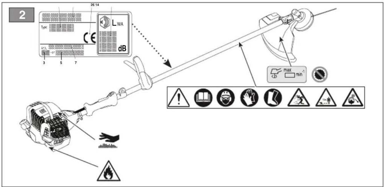
text_image
2 26 14 Type: CE LWA dB 3 5 7 max min 1 2 3 4 5 6 7 10 11 12 13 14 15 16 17 18 19 20 21 22 23 24 25 26 27 28 29 30 31 32 33 34 35 36 37 38 39 40 41 42 43 44 45 46 47 48 49 50 51 52 53 54 55 56 57 58 59 60 61 62 63 64 65 66 67 68 69 70 71 72 73 74 75 76 77 78 79 80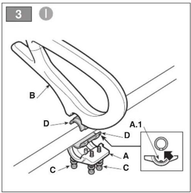
text_image
3 B D A.1 D A C C
text_image
4 II C A B E D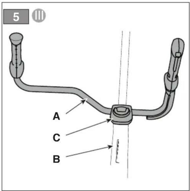
text_image
5 A C B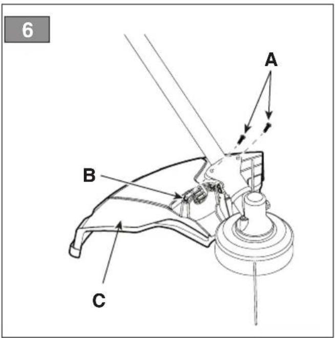
text_image
6 A B C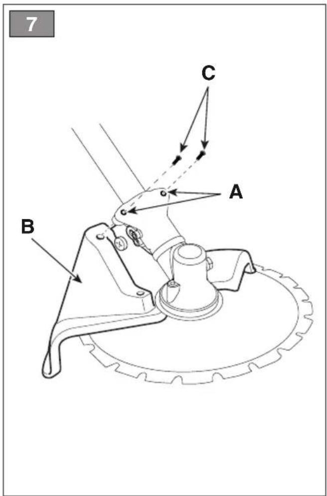
text_image
7 C A B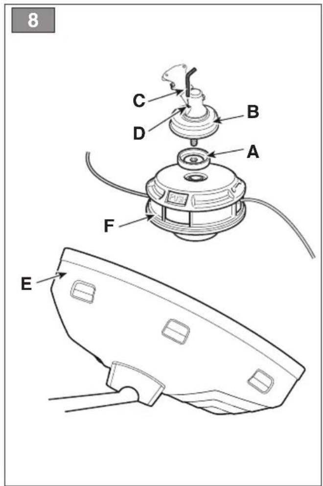
text_image
8 C B D A F E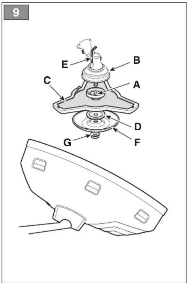
text_image
9 E B C A D G F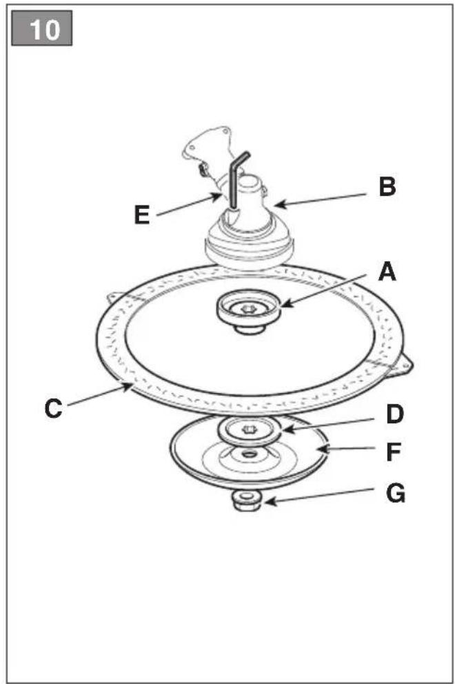
text_image
10 E B A C D F G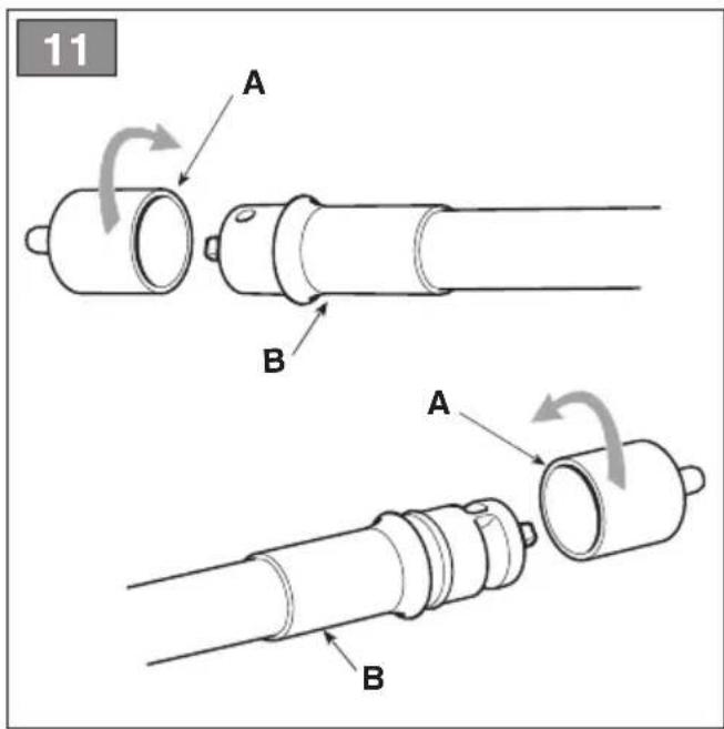
text_image
11 A B A B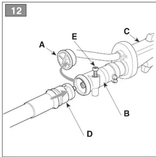
text_image
12 A E C B D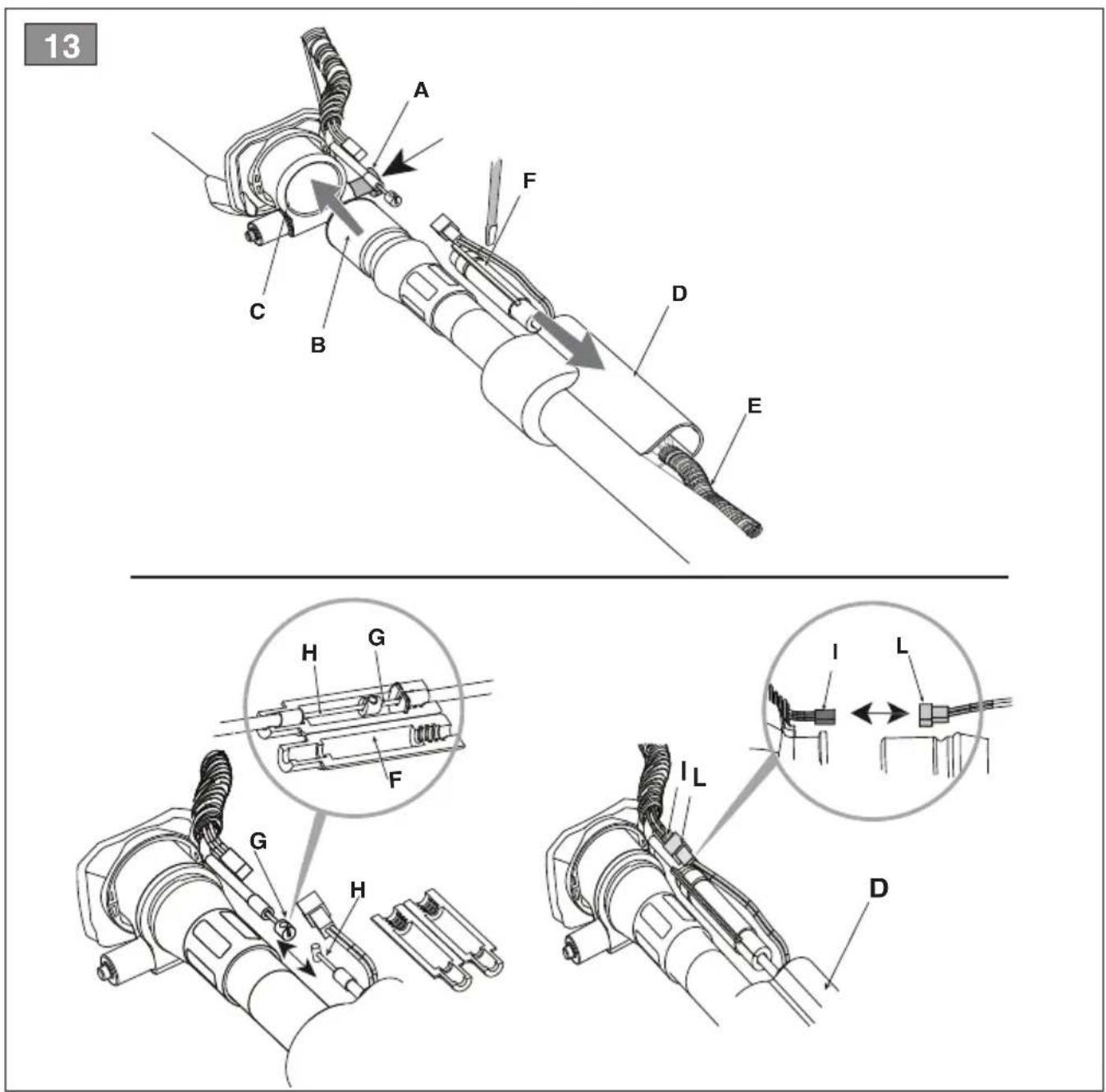
text_image
13 A F C B D E H G F I L G H I L D14
text_image
A STOP C I START B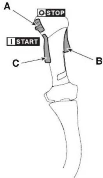
text_image
A O STOP I START C B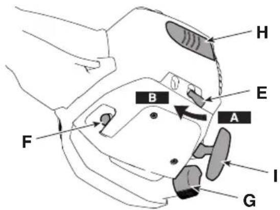
text_image
H B E A F I G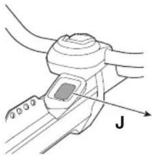
natural_image
Diagram of a mechanical device with a belt and lever, labeled 'J' (no text or symbols beyond label)
text_image
RPM / H M MAINTENANCE ✓ X15
text_image
A.6 A A.5 A.3 A.2 A.1 A.4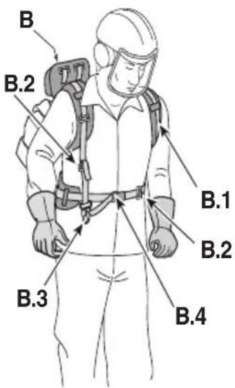
text_image
B B.2 B.1 B.2 B.3 B.4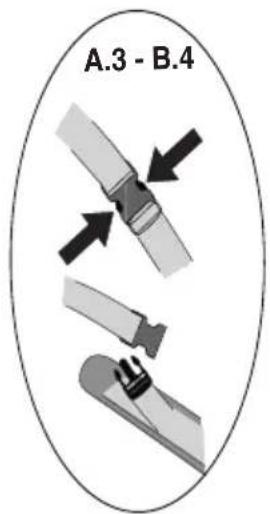
text_image
A.3 - B.4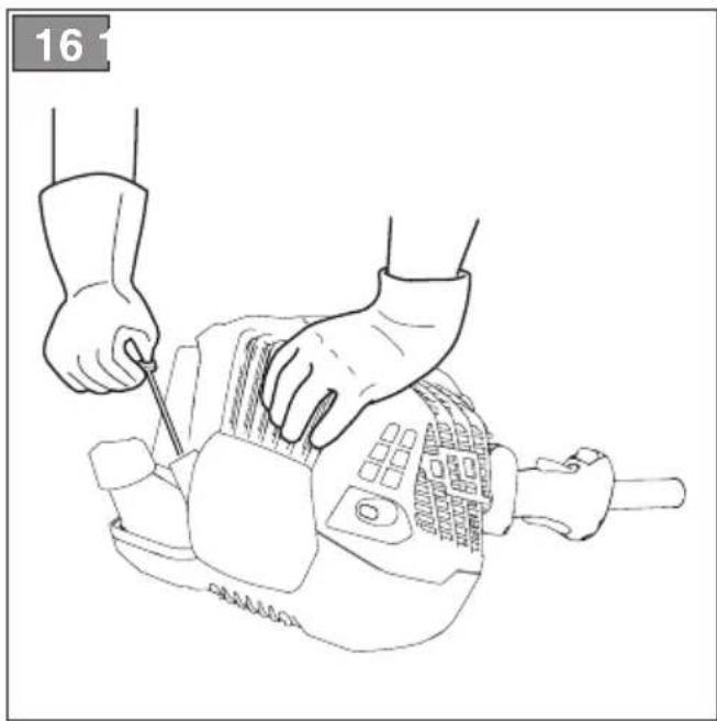
natural_image
Line drawing of hands using a power tool to cut or adjust a mechanical component (no text or symbols)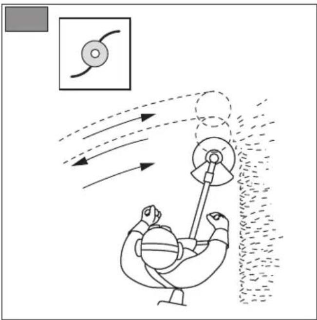
natural_image
Diagram of a mechanical device with motion arrows and a magnified inset showing a circular component (no text or symbols)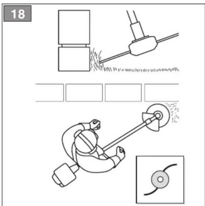
text_image
18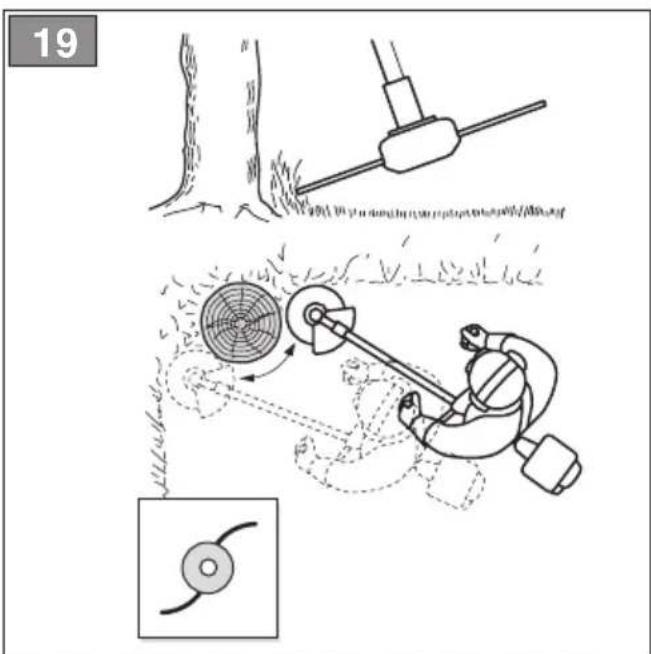
text_image
19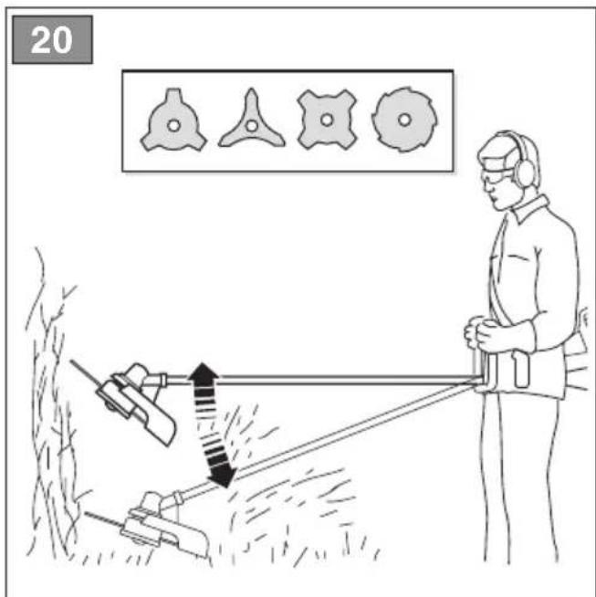
text_image
20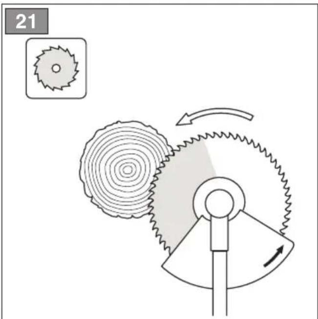
text_image
21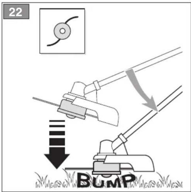
text_image
22 BUMP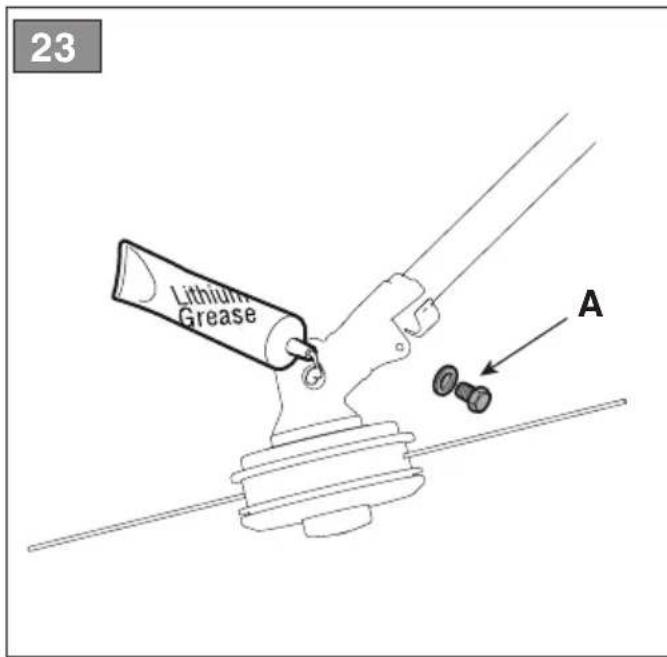
text_image
23 Lithium Grease A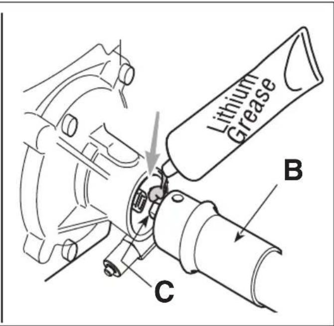
text_image
Lithium Grease B C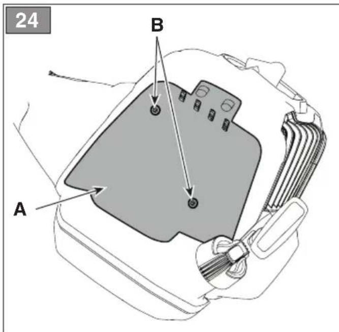
text_image
24 A B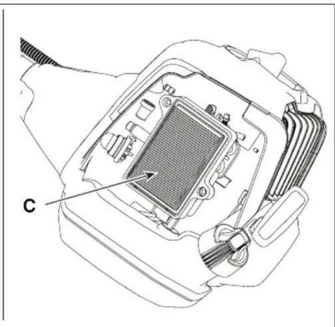
natural_image
Technical line drawing of an electronic device interior with labeled component 'C' (no text or symbols beyond label)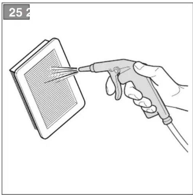
natural_image
Illustration of a hand using a power tool to probe a device on a screen (no text or symbols visible)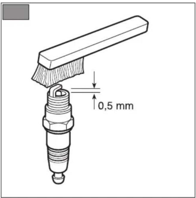
text_image
0,5 mm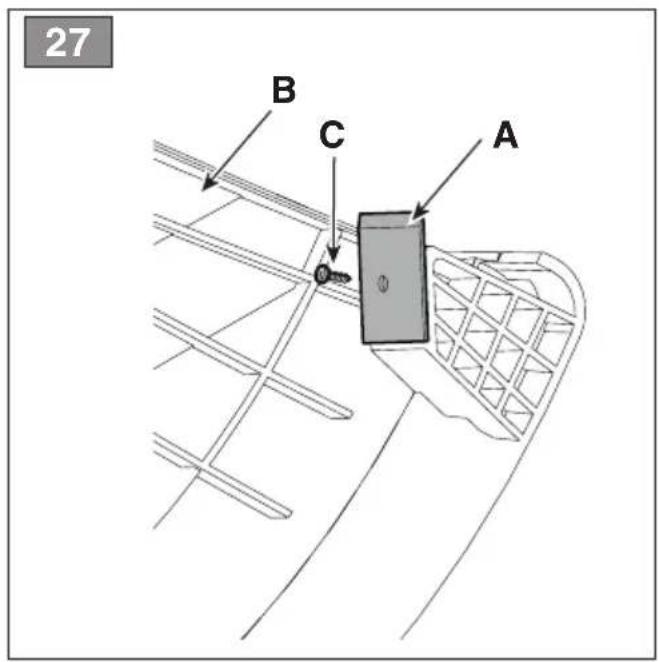
text_image
27 B C A28
I
natural_image
Diagram of a hand pressing a button on a mechanical component (no text or symbols)1
2
natural_image
Technical line drawing of a mechanical assembly with no visible text or symbolsA =
2 x 2,0 m (79 in.) - B 26/32 series
text_image
A3
4
natural_image
Diagram of a fan or impeller with internal blades and directional arrows indicating rotation (no text or symbols)5
6
B =
175 mm (6,9 in.) - B 42/52 series
natural_image
Technical illustration of a mechanical device with internal components and directional arrows indicating motion (no text or symbols)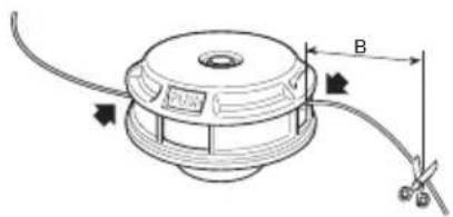
text_image
Technical diagram of a mechanical component with labeled dimensions B and directional arrows indicating assembly or assembly.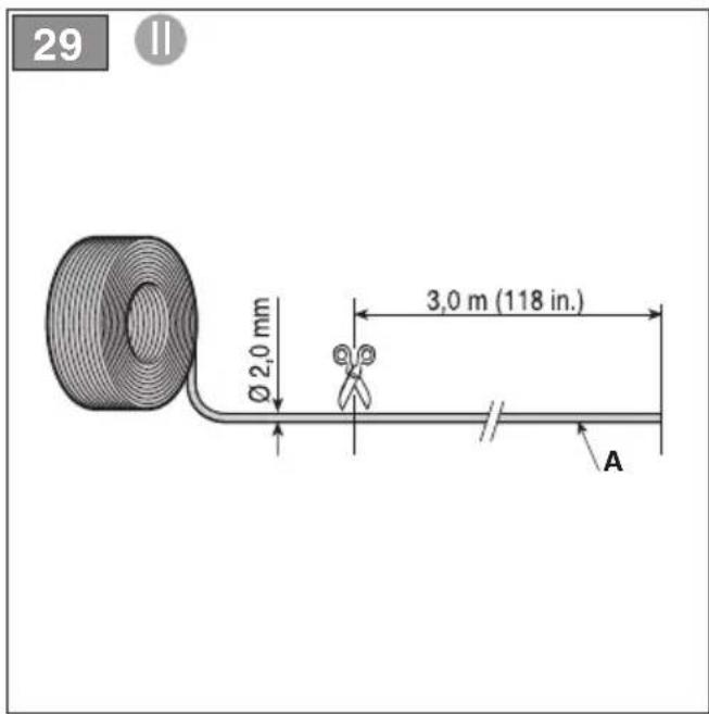
text_image
29 Ø 2,0 mm 3,0 m (118 in.) A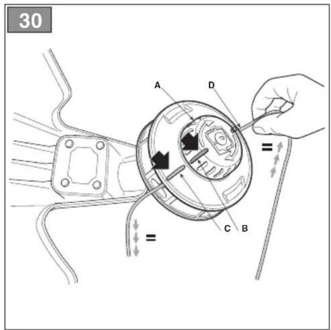
text_image
30 A D = = C B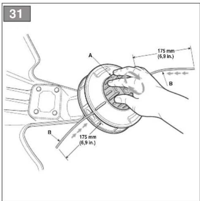
text_image
31 A 175 mm (6,9 in.) B B 175 mm (6,9 in.)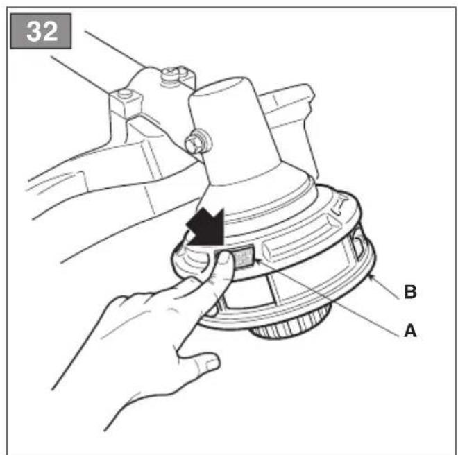
text_image
32 A B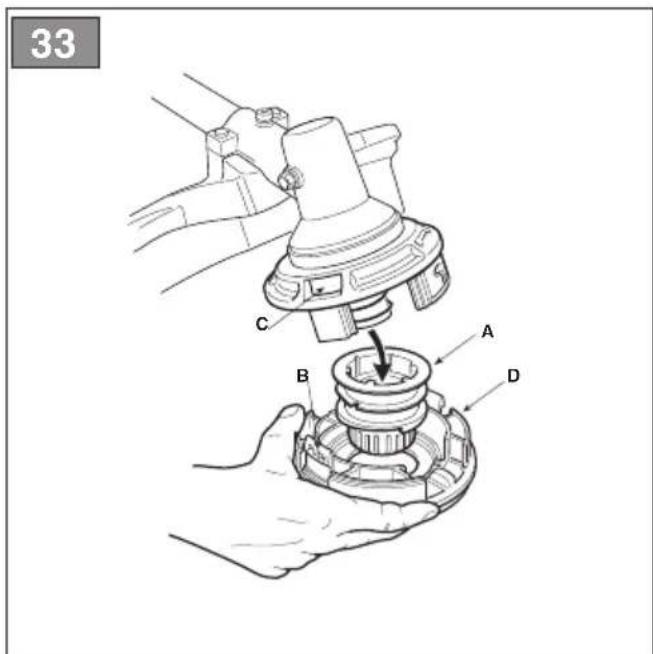
text_image
33 C A B D[3] 2-stroke air-cooled
[4] Displacement
[5] Power
[6] Engine rotation speed when idle
[7] Maximum engine rotation speed (cutting line head)
[8] Maximum engine rotation speed (blades)
[9] Maximum tool rotation speed (cutting line head)
[10] Maximum tool rotation speed (blades)
[11] Fuel tank capacity
[12] Fuel mixture (Petrol: 2-stroke oil)
[13] Spark plug
[14] Cutting width (cutting line head)
[15] Cutting width (3 point, 4 point and 8 point blade)
[16] Cutting width (saw blade)
[17] Connecting cutting line head
[18] Diameter of cutting line (max)
[19] Cutting means code
[20] Cutting means code (8 point blade)
[21] Cutting means code (saw blade)
[22] Protection code (wire holder head, 3 point, 4 point and 8 point blade)
[23] Protection code (saw blade)
[24]Weight
[25] Front, rear handle
[26]Handle bar
[27] Sound pressure level
[28] Uncertainty
[29] Measured sound power level
[30] Guaranteed sound power level
[31] Vibrations transmitted to hand on front handle
[32] Vibrations transmitted to hand on rear handle
[33] Vibrations transmitted to hand on right handle
[34] Vibrations transmitted to hand on left handle
[1] ES - DATOS TÉCNICOS
[2] Motor
[1] FI - TEKNISET TIEDOT
[2] Moottori
[1] LT - TECHNINIAI DUOMENYS
[2] Variklis
- USO DELLA MACCHINA....10
5.7 DISPLAY (SE PRESENTE)
6. USO DELLA MACCHINA
5.7 DISPLEJ (JE-LI SOUČÁSTÍ)
6.4 PRACOVNÍ ČINNOST
3.3 TYPESKILT PÅ PRODUKTET
5.7 DISPLAY (HVIS RELEVANT)
natural_image
Two black circular icons showing hand and sock symbols (no text or labels)- GENERAL INFORMATION .... 1
- SAFETY REGULATIONS....2
- ABOUT THE MACHINE .... 4
3.1 Machine description and intended use......4
3.2 Safety signs....5
3.3 Product identification label 5
3.4 Main components.... 6
- ASSEMBLY 6
4.1 Assembly components....6
4.2 Grip assembly 7
4.3 Selecting the cutting means and specific guard 7
4.4 Fitting the guard on the cutting means..... 7
4.5 Fitting and removing the cutting means ..... 8
4.6 Mounting the flexible drive-shaft tube....8
- CONTROLS....9
5.1 Engine start / stop switch....9
5.2 Throttle control lever....9
5.3 Throttle safety lever 9
5.4 Manual starting grip....9
5.5 Choke control lever (if available)....9
5.6 Primer control button....9
5.7 Display (if available) 9
- USING THE MACHINE 9
6.1 Preliminary operations.... 10
6.2 Safety checks.... 10
6.3 Start-up 11
6.4 Operation 12
6.5 Advice for operation 13
6.6 Stop....13
6.7 After use.... 13
- ROUTINE MAINTENANCE....13
7.1 General Information.... 13
7.2 Preparing the fuel blend 14
7.3 Refuelling 14
7.4 Cleaning the machine and the engine ..... 14
7.5 Nuts and bolts 15
- OCCASIONAL MAINTENANCE 15
8.1 Angle transmission lubrication: 15
8.2 Flexible drive-shaft lubrication....15
8.3 Cleaning the air filter.... 15
8.4 Spark plug 15
8.5 Cutting means maintenance.... 15
8.6 Sharpening the wire cutting blade 16
8.7 Adjusting idle speed....16
8.8 Carburettor....16
-
STORAGE....16
-
HANDLING AND TRANSPORT 17
- ASSISTANCE AND REPAIRS 17
- MAINTENANCE TABLE....18
- TROUBLESHOOTING 19
1. GENERAL INFORMATION
1.1 HOW TO READ THIS MANUAL
Some of the paragraphs in this manual contain particularly important information in terms of safety and operation, and are highlighted differently, according to the following criteria:
NOTE or IMPORTANT These give details or further information on what has been previously indicated and aim to prevent damage to the machine or cause other damage.
The symbol represents a danger. Failure to observe the warning can lead to possible personal and/or third party injury and/or damage.
The paragraphs highlighted in a dotted grey square indicate optional characteristics not available on all models documented in this manual. Check if the characteristics are available on this model.
Whenever reference is made to a position on the machine "front", "back", "left" or "right" hand side, this refers to the operator's working position.
1.2 REFERENCES
1.2.1 Figures
The figures in these instructions for use are numbered 1, 2, 3, etc.
Components shown in the figures are marked A, B, C, etc.
Reference to component C in figure 2 is indicated with the wording: "See fig. 2.C" or simply "(Fig. 2.C)".
The figures are provided by way of example. The actual pieces can differ from those illustrated in this document.
1.2.2 Titles
The manual is arranged in chapters and paragraphs. The title of paragraph '2.1 Training" is a sub-title of "2. Safety regulations". References to titles or paragraphs are marked with the abbreviation chap. or par. and the relevant number. Example: "chap. 2" or "par. 2.1."
2. SAFETY REGULATIONS
2.1 TRAINING
⚠️ Become familiar with the controls and the proper use of the machine. Learn how to stop the machine quickly. Failure to follow the warnings and instructions may result in fire and/or serious injury.
- National legislation may restrict the use of the machine.
- Never allow the machine to be used by children or individuals who are not familiar with the instructions. Local laws may establish a minimum age for users.
- Never use the machine if the user is tired or unwell, or has taken medication, drugs, alcohol or substances that impair reflexes and concentration.
- Remember that the operator or user is responsible for accidents and unexpected events that can occur to other people or property. It is the user's responsibility to assess the potential risk of the area where work is to be carried out and to take all the necessary precautions to ensure his own safety and that of others, particularly on slopes or rough, slippery and unstable ground.
- If the machine is sold or lent to others, make sure that the operator looks over the user instructions contained in this manual.
2.2 PRELIMINARY OPERATIONS
Personal Protective Equipment (PPE)
- Always wear slim-fitting protective clothes with slash-proof protection, anti-vibration gloves, helmet, protective goggles, half-mask respirator, protective earplugs, cut resistant safety boots with non-slip soles.
- Never wear scarves, shirts, necklaces, bracelets, loose flowing clothing, laces or ties or any hanging or flapping accessory that could catch in the machine or in any objects or materials in the work area.
- Tie your hair back if it is long.
Work / Machine Area
- Thoroughly inspect the entire work area and remove anything that could be thrown by the machine or damage the cutting means/rotating units (stones, branches, iron wire, bones, etc.).
Internal combustion engine: fuel
⚠️ DANGER! Petrol and blended fuels are highly flammable.
- Keep petrol and blended fuel in approved containers, in a safe place, away from any sources of heat or naked flames.
- Keep the containers out of the reach of children.
- Keep the containers free of residues of grass, leaves or excessive grease
- Do not smoke while blending the fuel, filling up/topping up with fuel or whenever handling the fuel.
– Use a funnel to top up with fuel only in the open air. - Do not inhale fuel fumes.
- Never remove the tank cap or add fuel while the engine is running or when the engine is hot.
- Open the fuel tank slowly to allow the pressure inside to decrease gradually.
- Do not approach the tank opening with a naked flame to check its contents.
– If you have spilt some fuel, do not attempt to start the engine but move the machine away from the area of spillage and avoid creating any source of ignition until the fuel has evaporated and fuel vapours have dissipated.
– Replace caps of all fuel tanks and containers securely.
– Immediately clean up all traces of fuel spilt on the machine or on the ground. - Never start the machine in the same place in which you refilled it with fuel; the engine must be started in an area at least 3 metres from where you refuelled.
- Avoid getting any fuel or your clothing and, if this should happen, change your clothes before starting the engine.
2.3 DURING OPERATION
Work Area
- Do not operate the engine in confined spaces where dangerous carbon monoxide fumes can collect. The start-up operations must be carried out outdoors or in a well-ventilated area. Always remember that the exhaust gases are toxic.
- When starting up the machine, do not direct the silencer and therefore the exhaust fumes towards flammable materials.
- Do not use the machine in environments that pose the risk of explosion, in the presence of flammable liquids, gases or powders. Electrical contact or
mechanical rubbing can generate sparks that can ignite powder or vapour.
- Work only in daylight or with good artificial light in good visibility conditions.
- Keep people, children and animals away from the work area. Children must be supervised by another adult.
- Make sure that no persons are within 15 metres of the machine's range of operation or within 30 metres for heavier cutting.
- Where possible, avoid working on wet, slippery ground or on uneven or steep ground that does not guarantee stability for the operator.
- Pay careful attention to uneven ground (hills, dips), slopes, hidden hazards and obstacles that could limit visibility.
- Be very careful near ravines, ditches or embankments.
- Always work across the face of the slope and never up and down it, being very careful when changing direction, making sure the cutting means is always down-line.
- Look out for traffic when using the machine near the road.
Conduct
- When working, the machine must always be held firmly in both hands, keeping the power unit on the right of the body and the cutting head below the line of the belt.
• Always use caution and take on a firm and well-balanced position. - Never run, always walk.
• Always keep the machine connected to the harness when working.
• Always keep hands and feet away from the cutting means, when starting and when using the machine. - Attention: the cutting means will continue to rotate for a few seconds after disengagement or after you have switched off the engine.
- Be careful of flying debris coming from the cutting means.
- Be careful of avoiding violent collisions between the cutting means and foreign objects/obstacles. Kickback may occur if the cutting means comes into contact with an obstacle/object. This contact can cause a rapid jerk in the opposite direction, pushing the cutting means up and towards the operator. Kickback can cause the operator to lose control of the machine, leading to serious consequences. To avoid kickbacks, take all the appropriate precautions indicated below:
– Firmly hold the machine, with two hands, and place your body and arms in a position that allows you to resist kickback.
- Do not extend the arms too high and do not cut above waist height.
-
Only use the cutting means specified by the manufacturer.
– Follow the manufacturer's instructions concerning cutting means maintenance. -
Beware of injuries caused by devices used to cut the line length.
- Attention: The cutting element continues to rotate even after the engine has been switched off.
- Do not touch the parts of the engine that heat up during operation. Risk of burns.
- To avoid the risk of fire, do not leave the machine with the engine hot on leaves or dry grass or other flammable material.
- If something breaks or an accident occurs during work, turn off the engine immediately and move the machine away to prevent further damage; if an accident occurs with injuries or third parties are injured, carry out the first aid measures most suitable for the situation immediately and contact the medical authorities for any necessary health care. Carefully remove any debris which could cause damage or injury to persons or animals if ignored.
- The noise and vibration levels shown in these instructions are the maximum levels for use of the machine. The use of an unbalanced cutting element, the excessive speed of movement, or the absence of maintenance have a significant influence on noise emissions and vibrations. Consequently, it is necessary to take preventive steps to eliminate possible damage due to high levels of noise and stress from vibration; maintain the machine well, wear ear protection devices, and take breaks whilst working.
- Prolonged exposure to vibrations can cause injuries and neurovascular disorders (also called “Raynaud’s syndrome” or “white finger”), especially to people suffering from circulation disorders. The symptoms can regard the hands, wrists and fingers and are shown through loss of sensitivity, torpor, itching, pain and discolouring of or structural changes to the skin. These effects can be worsened by low ambient temperatures and/or by gripping the hand grips excessively tightly. If the symptoms occur, the length of time the machine is used must be reduced and a doctor consulted.
Restrictions of use
- Do not use the machine if you are unable to hold it with both hands or keep steady on your legs whilst working.
- Never use the machine with damaged, missing or incorrectly positioned guards.
- Do not change the engine adjustments, or exceed the maximum rpm. If the engine is forced to run at an excessive speed, the risk of personal injury increases.
- Do not strain the machine too much and do not use a small machine for heavy-duty work; if you use the right machine, you will reduce the risk of hazards and improve the quality of your work.
2.4 MAINTENANCE, STORAGE AND TRANSPORT
Ensure regular maintenance and correct storage to maintain machine safety and high performance levels.
⚠️ Never use the machine with worn or damaged parts. Faulty or worn-out parts must always be replaced and never repaired. Only use original parts: using parts that are not original or installed incorrectly affects machine safety, and can therefore cause accidents or personal injury and relieve the Manufacturer of all obligations and liability.
Maintenance
- To reduce the risk of fire, check for oil and/or fuel leaks on a regular basis.
- Be careful during adjustment of the machine to prevent entrapment of the fingers between moving parts of the cutting means and fixed parts of the machine.
Storage
- Do not store the machine with fuel in the tank in an area where fuel vapours could reach a naked flame, spark or strong source of heat.
- To reduce fire risks, do not leave containers with debris inside a room.
2.5 ENVIRONMENTAL PROTECTION
Protecting the environment must be a significant and top priority for machine use, to the benefit of civil co-habitation and of the environment that we live in.
- Avoid being an element of disturbance to the surrounding area. Use this machine at reasonable times of the day only (not early morning or late evening when the noise could cause disturbance).
- Adhere strictly to the local regulations governing the disposal of packaging, oil, fuel, filters, damaged parts or any other element which may have an impact on the environment; this waste must not be disposed of with regular waste, but must be separated and taken to collection centres, which will recycle the materials.
- Comply with local regulations for the disposal of waste materials.
- When the machine is withdrawn from service, do not dispose of it in the environment, but take it to a waste disposal facility in accordance with the local regulations in force.
3. ABOUT THE MACHINE
3.1 MACHINE DESCRIPTION AND INTENDED USE
This machine is gardening equipment and, specifically, a portable bush/edge trimmer with a thermal engine, designed for hobby use.
The machine essentially comprises of an engine which, through a drive shaft enclosed in a tube and an angle transmission unit, drives a cutting means configured in various ways to perform various functions.
The operator is able to sustain the machine with the aid of a harness and can operate the main controls, always keeping at a safe distance from the cutting means.
3.1.1 Intended use
This machine was designed and manufactured for:
• cutting grass and non-woody vegetation with a nylon line enclosed in a cutting line head;
• cutting tall grass, dry branches, twigs and woody shrubs of up to 2cm diameter, with the aid of metal or plastic blades;
• cutting wooden parts and felling small trees (only with saw blade, if allowed);
- being used by one operator.
3.1.2 Improper use
Any other use that does not comply with the above, can be dangerous and cause damage to people and/or property. Examples of improper use may include, but are not limited to:
• using the machine for sweeping;
- trimming hedges or other jobs in which the cutting means is not used at ground level;
- pruning trees;
- using the machine with the cutting means above the operator's belt level;
• using the machine for cutting non-plant material;
- using cutting means other than those found in the "Technical Data" table. Risk of serious injury and injuries;
• using of the machine by more than one person.
IMPORTANT Improper use of the machine will void the warranty and relieves the Manufacturer of any liability, placing all responsibility for damage or injury, to him/herself or third parties, on the user.
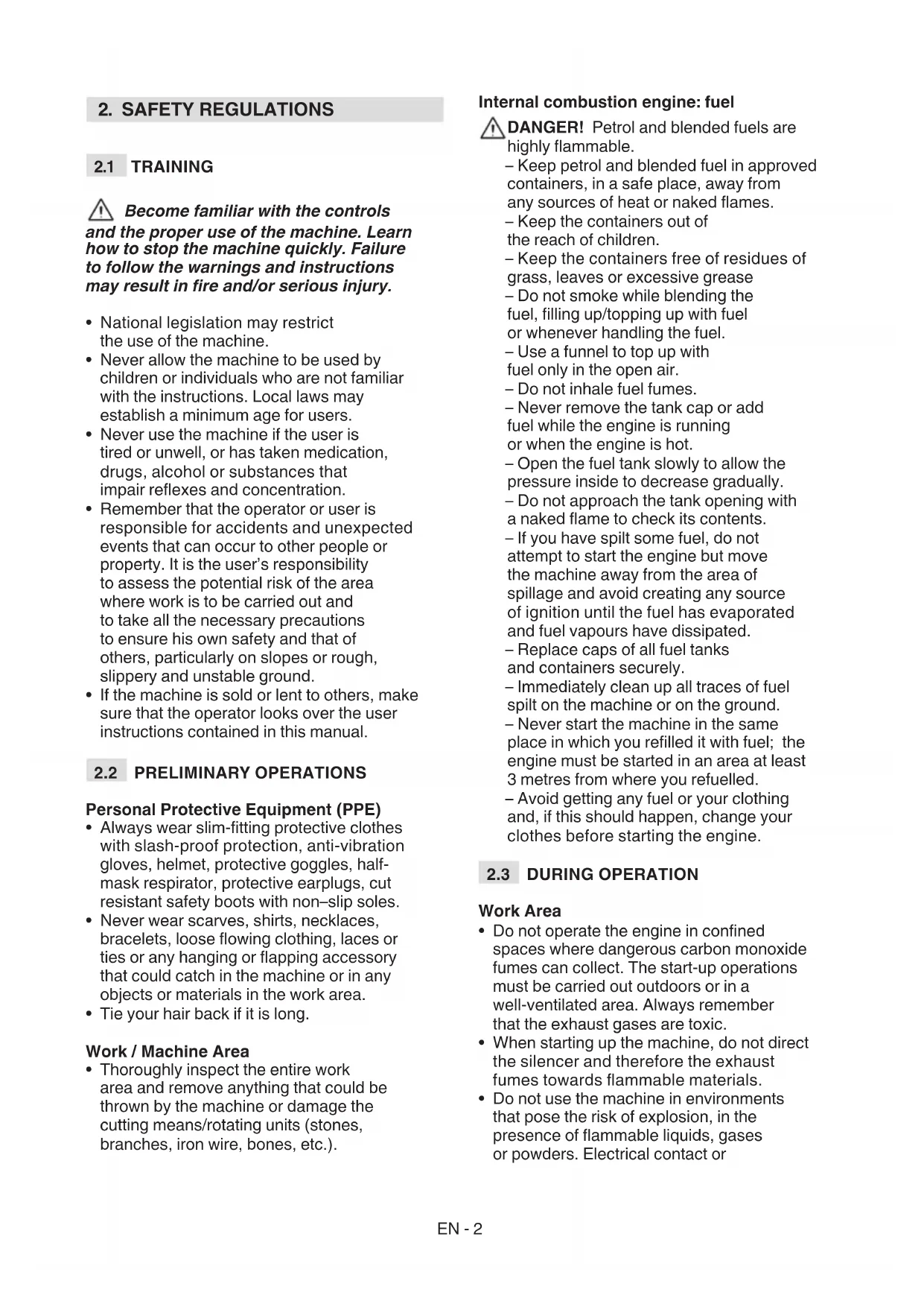
3.2 SAFETY SIGNS
The machine has various symbols on it (fig. 2). Their function is to remind the operator of the correct conduct for use, with due care and caution.
Meanings of the symbols:

WARNING! DANGER! The failure to use this machine correctly can be hazardous for oneself and others.

WARNING! Read the owner's manual before using the machine.

Anyone operating the machine under normal conditions for continuous daily use may be exposed to a noise level equal to or exceeding 85 dB (A). Use ear protection devices, goggles and helmet.

Wear protective gloves and safety footwear.


PROJECTION HAZARD! People or pets must be kept at least 15 m away when using the machine!


Maximum speed of the cutting means.

Do not use circular saw blades. Danger: Using circular saw blades on models that are not designed for them exposes the user to the risk of very serious or even fatal injuries.

WARNING! Petrol is flammable. Allow the engine to cool at least 2 minutes before refuelling.

Beware of blade kickback.

WARNING! - Keep away from hot surfaces.
IMPORTANT Any damaged or illegible decals must be replaced. Order replacement decals from an Authorised Service Centre.
3.3 PRODUCT IDENTIFICATION LABEL
The product identification label provides the following data (Fig. 2):
- Sound power level
- Conformity marking
- Month / Year of manufacture
- Type of machine
- Serial number
- Name and address of Manufacturer
- Article code
Write the identification data of the machine in the specific space on the label on the back of the cover page.
IMPORTANT Quote the information on the product identification label whenever you contact an Authorised Service Centre.
IMPORTANT An example of the Declaration of Conformity is provided on the last pages of this manual.
3.4 MAIN COMPONENTS
The machine is composed of a series of main components that have the following functions (Fig.1):
A. Engine: drives the cutting means via drive tube and angle transmission.
B. Transmission tube: The tube houses the drive shaft which transmits rotary motion to the angle transmission.
1. Drive tube.
2. Flexible drive tube
C. Angle transmission: final part of the transmission tube that transmits motion to the cutting means.
D. Cutting means: the element designed to cut vegetation
1. Cutting line head: nylon line cutting means.
2. 3 point, 4 point and 8 point blades: metal disk cutting means.
3. Saw blade (if allowed): circular metal disk cutting means with peripheral cutting teeth.
E. Cutting means guard: it is a safety device which prevents objects drawn up by the cutting means from being hurled away from the machine.
-
Cutting line head.
-
Saw blade (if allowed)
F. Front hand grip: semi-circular shaped, it is used to handle the machine and is equipped with a leg guard.
G. Rear hand grip: used to handle the machine and equipped with the main on/off/acceleration control buttons.
H. Leg guard: a safety guard that prevents accidental contact with the cutting means during use.
I. Handle bar: "ox horn" shaped handle bar transversely placed to the rod and asymmetrically to it; used to control the machine and equipped, on the right hand side, with the main on/off/acceleration control buttons.
J. Display: information regarding the machine operation and maintenance is displayed.
K. Connection point (of the harness): where the harness is connected to the machine.
L. Harnessing: device made up of a fabric belt which, placed over the shoulders, helps to support the weight of the machine during work:
-
double strap.
-
with back-pack power unit
M. Blade protection (for machine transport and handling): protects against accidental contact with the cutting means that can cause serious injuries.
4. ASSEMBLY
IMPORTANT The safety regulations to follow are described in chap. 2. Strictly comply with these instructions to avoid serious risks or dangers.
For storage and transport purposes, some components of the machine are not installed in the factory and have to be assembled after unpacking. Follow the instructions below.
⚠️ Unpacking and completing the assembly should be done on a flat and stable surface, with enough space for machine handling and its packaging, always making use of suitable equipment. Do not use the machine until all the indications provided in the “ASSEMBLY” section have been carried out.
4.1 ASSEMBLY COMPONENTS
The packaging includes assembly components.
4.1.1 Unpacking
-
Carefully open the packaging, paying attention not to lose components.
-
Consult the documentation in the box, including these instructions.
- Remove all the unassembled parts from the box.
- Slide the trimmer-cutter out of the box.
- Dispose of the box and packaging in compliance with local regulations.
4.2 GRIP ASSEMBLY
4.2.1 Assembly of the front hand grip - Type I
- Position the cap (Fig. 3.A) by inserting the pin (Fig. 3.A.1) into one of the holes available on the transmission tube.
- Fit the front grip complete with leg guard barrier (Fig. 3.B) using the screws (Fig. 3.C), taking care to keep the two anti-vibration half-shells in place (Fig.3.D).
- Fully tighten the screws (Fig. 3.C).
4.2.2 Fitting the handle bar - Type II
- Unscrew the central knob (Fig. 4.A) and remove the cap (Fig. 4.B).
- Insert the handle bar (Fig. 4.C), making sure that the controls are on the right.
- Arrange the handle bar in the most comfortable working position and lock it using the cap (Fig. 4.B) and the knob (Fig. 4.A).
- Hook up the control sheath (Fig. 4.D) to the appropriate cable clamp (Fig. 4.E).
NOTE Loosen the knob (Fig. 4.A) in order to rotate the handle bar and reduce its overall dimensions for storage purposes.
4.2.3 Fitting the handle bar - Type III
- Insert the handle (Fig. 5.A) into its seat in the transmission tube (Fig. 5.B), making sure that the controls are on the right.
- Tighten and lock the knob (Fig. 5 C) on the handle bar (Fig. 5 A).
4.3 SELECTING THE CUTTING MEANS AND SPECIFIC GUARD
⚠️ Every cutting means must be fitted with a specific guard, as indicated by the following directions in the Technical Data table.
Choose the most suitable cutting means for the job to be done, according to these general instructions:
- the cutting line head can eliminate tall grass and non-woody vegetation near fences, walls, foundations, pavements, around trees, etc. or to completely clean a particular area of the garden;
- the 3-point, 4-point and 8-point blades are suitable for cutting brushwood and small shrubs up to 2cm in diameter;
- the saw blade (if allowed) is used to cut wooden parts and fell small trees;
IMPORTANT Whenever you have to change the cutting means, disassemble all its elements.
4.4 FITTING THE GUARD ON THE CUTTING MEANS
⚠ Wear protective gloves.
4.4.1 Fitting the cutting means guard (wire holder head, 3-point, 4-point and 8-point blade)
- Unscrew the screws (Fig. 6.A).
- Position the guard (Fig. 6.C) in line with the holes on the transmission (Fig. 6.B).
- Secure the guard (Fig. 6.A) fully tightening the screws (Fig. 6.C).
NOTE The cutting means guard
(Fig. 1.E) has the following symbol:

It indicates the rotation direction of the cutting means.
4.4.2 Mounting the cutting means guard (saw blade, if allowed)
This protective guard should not be used for other cutting means.
- Remove any protective guards used for other cutting means.
- Position the guard (Fig. 7.B) in line with the holes on the transmission (Fig. 7.A).
- Secure the guard (Fig. 7.A) by fully tightening the screws (Fig. 7.C).
4.5 FITTING AND REMOVING THE CUTTING MEANS

Wear protective gloves.
4.5.1 Fitting the cutting line head
- Fit the inner lock ring (Fig.8.A) on the shaft in the indicated direction, making sure that the grooves are perfectly coupled with those on the angle transmission (Fig. 8.B).
- Insert the wrench supplied (Fig. 8.C) into the appropriate hole on the angle transmission (Fig. 8.D) and rotate the lock ring by hand by pushing the wrench (Fig. 8.C) until it engages and blocks rotation.
- Fit the cutting wire head (Fig. 8.F) by screwing it anticlockwise.
- Remove the wrench (Fig. 8.C) to reset rotation.
IMPORTANT When using the wire head, the guard (Fig. 8.E) must always be fitted with a wire cutter blade (Fig. 24.A).
4.5.2 Removing cutting wire head
- Insert the wrench supplied (Fig. 8.C) into the appropriate hole on the angle transmission (Fig. 8.D) and rotate the lock ring by hand by pushing the wrench (Fig. 8.C) until it engages and blocks rotation.
- Remove the wire holder head (Fig. 8.F) by unscrewing clockwise.
4.5.3 Fitting the 3-point, 4-point and 8-point blade and saw blade (if allowed)

Apply the guard to the blade.
- Mount the inner locking ring (Fig. 9.A, Fig. 10.A) on the shaft in the indicated direction, making sure that the grooves are perfectly coupled with those on the angle transmission (Fig. 9.B, Fig. 10.B).
- Fit the blade (Fig. 9.C, Fig. 10.C) and the outer locking ring (Fig. 9.D, Fig. 10.D) with the flat part facing the blade.
- Insert the wrench supplied (Fig. 9.E, Fig. 10.E) into the special hole on the transmission, rotate the blade by hand (Fig. 9.C, Fig. 10.C) and push the wrench (Fig. 9.E, Fig. 10.E) until it engages in the angle transmission hole (Fig. 9.B, Fig. 10.B) and locks rotation.
- Fit the sump (Fig. 9.F, Fig. 10.F) and tighten the nut (Fig. 9.G, Fig. 10.G) fully anticlockwise (25 Nm).
- Remove the wrench (Fig. 9.E, Fig. 10.E) to reset rotation.
4.5.4 Removing the 3-point, 4-point and 8-point blade and saw blade (if allowed)

Apply the guard to the blade.
- Insert the wrench supplied (Fig. 9.E, Fig. 10.E) into the special hole, rotate the blade by hand (Fig. 9.C, Fig. 10.C) and push the wrench (Fig. 9.E, Fig. 10.E) until it engages in the angle transmission hole (Fig. 9.B, Fig. 10.B) and locks rotation.
- Unscrew the nut (Fig. 9.G, Fig. 10.G) clockwise and remove the sump (Fig. 9.F, Fig. 10.F).
- Remove the outer locking ring (Fig. 9.D, Fig. 10.D); then remove the blade (Fig. 9.C, Fig. 10.C) and the inner locking ring (Fig. 9.A, Fig. 10.A).
4.6 MOUNTING THE FLEXIBLE DRIVE-SHAFT TUBE
- Remove the protective cuffs (Fig. 11.A) from both ends of the flexible drive tube (Fig. 11.B), taking note that there are differences between them.
-
Remove the protection cap (Fig. 12.A) from the tube (Fig. 12.B) protruding from the rear handgrip (Fig. 12.C).
-
Insert the end with the groove (Fig. 12.D) in the protruding tube (Fig.12.B) of the rear handgrip (Fig. 12.C) and fasten it with the screw (Fig. 12.E) ensuring it stays locked.
- Press the pin (Fig. 13.A) and insert the flexible (Fig. 13.B) in the seat of the power unit (Fig. 13.C).
- Release the pin (Fig. 13.A), making sure it is lowered completely to lock the end of the tube (Fig. 13.B).
- Remove the rubber protection (Fig.13.D) and pass the cables through it. (Fig.13.E)
- Open the throttle cable protection device with the help of a screwdriver (Fig.13.F)
- Connect the cables (Fig.13.G) with (Fig.13.H)
- Close the protection device (Fig.13.F)
- Connect the connectors (Fig.13.I) with (Fig.13.L)
- Put the rubber protection back (Fig.13.D)
5. CONTROLS
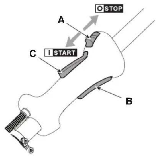
5.1 ENGINE START / STOP SWITCH
Used to start and stop the engine. The switch has two positions (Fig. 14.A):

STOP - the engine stops and cannot be started.

START - the engine can be started and operated.
5.2 THROTTLE CONTROL LEVER
Used to adjust the speed of the cutting means.
The throttle safety lever (Fig. 14.B) can only be operated if the throttle safety lever is pressed at the same time (Fig. 14.C).
The correct working speed is set using throttle safety lever (Fig. 14.B) to the end of its stroke.
5.3 THROTTLE SAFETY LEVER
The throttle safety lever (Fig. 14.C) allows the throttle control lever to be used (Fig. 14.A).
5.4 MANUAL STARTING GRIP
Allows the engine to be started by hand (Fig. 14.1).
5.5 CHOKE CONTROL LEVER (IF AVAILABLE)
It is used to cold start the engine. The control features two positions (Fig. 14.E):

Position A - The choke is disengaged (normal operation and hot engine start).

Position B - The choke is engaged (for engine cold start).
5.6 PRIMER CONTROL BUTTON

Press the primer's rubber button to inject fuel into the carburettor, thereby making it easier to start the engine (Fig. 14.F).
5.7 DISPLAY (IF AVAILABLE)
The display (Fig. 14.J) shows information regarding the machine operation and maintenance.

Tachometer.
The digits on the display show the number of engine rpm.

Timer.
The digits on the display show the machine's hours (H) and minutes (M) of operation.
MAINTENANCE Maintenance.
Icon indicates that no maintenance is required.
Icon starts to flash when the maintenance hourly threshold is reached. The frequency and types of maintenance are summarised in the "Maintenance Table" (see chapter 13). The flashing continues for 1 hour.
6. USING THE MACHINE
IMPORTANT The safety regulations to follow are described in chap. 2. Strictly comply with these instructions to avoid serious risks or dangers.
IMPORTANT The machine is supplied without fuel.
6.1 PRELIMINARY OPERATIONS
Before using the machine:
- place the machine in a stable horizontal position on the ground;
- choose the most suitable cutting means for the job to be done (par. 4.3);
- fill up with fuel. For information about how to prepare the fuel blend, methods and precautions for refuelling, see sections 7.2 and 7.3;
- wear the harness correctly (see section 6.1.1).
6.1.1 Using the harness
The straps must be adjusted in accordance with the height and build of the operator.
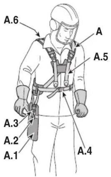
- Models with double strap
The harness must be worn before securing the machine to the attachment.
The strap (Fig. 15.A) must be worn with:
– the support (Fig. 15.A.1), the machine's carabiner hook (Fig.15.A.2). and the quick release hook (Fig. 15.A.3) on the right side.
– the quick release at the front (Fig. 15.A.4);
– the strap crossover on the back of the operator (Fig. 15.A.6);
– the buckles correctly fastened (Fig. 15.A.5).
The straps must be tightened so that they distribute the load evenly over the shoulders.
IMPORTANT In case of danger, unhook the machine using the quick release (Fig. 15.A.3).
- Models with back-pack harness
Harness with back-pack must be worn after starting the machine.
The harness (Fig. 15.B) must be worn with:
– the harness straps on the operator's shoulders (Fig. 15.B.1);
– the buckles properly fastened (Fig. 15.B.2).
– the snap-hook coupling on the right side (Fig. 15.B.3);
– the quick release in front (Fig. 15.B.4).
The belts must be tensioned so that the load is evenly distributed on the shoulders.
IMPORTANT In case of danger, unhook the harness using the quick release (Fig. 15.B.4).
6.2 SAFETY CHECKS
Run the following safety checks and ensure that the results correspond to those outlined in the tables.
⚠️ Always carry out the safety checks before use.
6.2.1 General check
| Object Result | |
| Grips (Fig. 1.F, Fig. 1.G, Fig. 1.I) | Clean, dry and fixed firmly to the machine. |
| Cutting means guard: (Fig. 1.E) | Suitable for the cutting means used, correctly and securely attached to the machine, not worn/ deteriorated or damaged. |
| Harness connection point (Fig. 1.J). | Correctly positioned. |
| Quick release (Fig.15.A.3, Fig. 15.B.4) | Efficient. It must allow the machine to be released quickly in case of danger. |
| Screws on the machine and the cutting means. | Correctly tightened (not loose) |
| Cutting means (Fig. 1.D.1, Fig. 1.D.2, Fig. 1.D.3) | Not damaged or worn |
| Metal blade (if fitted) (Fig. 1.D.2, Fig. 1.D.3, ) | Well sharpened. |
| Air filter (Fig. 24.C) Clean | |
| Electrical cables and spark plug cable. | In good condition to avoid causing sparks. |
| Spark plug cap (Fig. 14.H) | In good condition and correctly fitted on the spark plug |
6.2.2 Machine operating test
| Action Result | |
| Start the machine (section 6.3); | The cutting means (Fig. 1.D.1, Fig. 1.D.2, Fig. 1.D.3) must not move when the engine is idling. |
| Simultaneously activate the throttle control lever (Fig. 14.B) and throttle safety lever (Fig. 14.C). | They must be able to move freely without forcing. |
| Release the throttle control lever (Fig. 14.B) and the throttle safety lever (Fig. 14.C) | The levers must return automatically and quickly to the neutral position and the engine must return to idle speed. |
| Press the accelerator control lever (Fig. 14.B) | The throttle lever remains locked (Fig. 14.B). |
| Operate the engine start/stop switch (Fig. 14.A) | The switch must move easily from one position to another. |
⚠️ If any of the results fail to match the indications provided in the tables below, it is not possible to use the machine! Take it to a service centre to be checked and repaired if necessary.
6.3 START-UP
Before starting the engine:
- arrange the machine in a stable position on the ground;
- remove the cutting means guard (Fig. 1.M) (if used);
- make sure that the blade (Fig. 1.D.2, Fig. 1.D.3) (if fitted) does not touch the ground or other objects.
6.3.1 Cold start
⚠️ "Cold" start means starting performed at least 5 minutes after stopping the engine or after refuelling.
IMPORTANT To prevent deformation, the transmission tube must not be used as a support for hands or knees during start-up.
IMPORTANT To avoid breakage, do not pull the rope along its entire length, do not slide it along the edge of the guide hole and release the knob gradually to prevent it rewinding in an uncontrolled way.
- Make sure that the switch (Fig.14.A) is in position "I".
- only for models with choke: Engage the choke, moving the lever to "B" position (Fig. 14.E).
- Press the primer control button (Fig. 14.F) 10 times to facilitate carburettor ignition. Make sure the hole is covered by your finger when you press the command.
- Hold the machine firmly on the ground, with one hand on the drive unit, to avoid losing control of it when starting (Fig. 16).
- Slowly pull the starter knob by 10-15cm, until you feel a certain resistance, and then pull again a few times until you hear the first combustions.
- only for models with choke: Disengage the choke, moving the lever to "A" position (Fig. 14.E).
- Pull the starter knob again until the engine is properly switched on.
- Operate the throttle lever briefly (Fig. 14.B) and set the engine to idle.
- Allow the engine to idle for at least 1 minute before using the machine.
IMPORTANT If the starter rope knob is operated repeatedly, the engine may choke and start up may become difficult. If the engine floods in this way, see section 14.
6.3.2 Hot start
For hot start (immediately after stopping the engine), follow steps 1 - 2 - 3 - 4 - 6 - 7 of the previous procedure.
6.4 OPERATION
NOTE Before starting any tasks for the first time, get to know the machine, learn the most suitable cutting techniques, make sure your are wearing the harness correctly, grip the machine firmly and make the movements required by the job.
To use the machine proceed as follows:
- always keep the machine connected to the correctly worn harness (see par. 6.1.1).
- when working, the machine must always be firmly held in both hands, keeping the power unit on the right of the body and the cutting unit below the line of the belt.
6.4.1 Work techniques
6.4.1.a Cutting line head
⚠️ Use ONLY nylon lines. The use of metal lines, plastic coated metal lines and/or lines that are not suitable for the head can cause serious injuries and wounds.
Do not use the machine for sweeping, tilting the cutting line head. The engine is powerful enough to throw objects and small stones 15 metres or more, causing damage to objects and injury to people;
a. Cutting motion (Scything)
Proceed at a regular pace, with a circular motion similar to a traditional scythe, without tilting the cutting line head during the operation (Fig. 17).
First try cutting at the right height in a small area, so as to then achieve a uniform cutting height keeping the cutting line head at a
constant distance from the ground.
For heavier cutting it can be useful to tilt the cutting line head to the left by about 30^ .
Do not work in this way if there is the possibility of causing objects to be thrown, which could harm people, animals or cause damage.
b. Precision cutting (Trimming)
Keep the machine slightly tilted so that the lower part of the cutting line head does not touch the ground and the cutting line is at the
required point, always keeping the cutting means at a distance from the operator.
c. Cutting near fences/foundations
Move the cutting line head slowly towards fences, posts, rocks, walls, etc. without hitting them hard (Fig. 18). If the line strikes a solid object it could break or become worn; if it gets tangled in a fence it could break suddenly. In any case, cutting around pavements, foundations, walls, etc. can cause greater wear than normal to the line.
d. Cutting around trees
Walk round the tree from left to right, approaching the trunks slowly so as not to strike the tree with the line and keeping the cutting line head tilted forward slightly (Fig. 19). Remember that the nylon line could lop off or damage small shrubs and that the impact of the nylon line against the trunk of bushes or trees with soft bark could seriously damage the plant.
6.4.1.b 3 point, 4 point and 8 point blades:
Start cutting from above the vegetation and then descend with the mowing blade to cut branches by chopping them into small pieces (Fig. 20).
6.4.1.c Saw blade (if allowed):
⚠️ Where permitted, the saw blade must be used with the specific guard always fitted (section 4.4.2). The blade should always be well sharpened to reduce the risk of kickbacks.
When felling small trees, assess the direction of fall of the tree when cut, taking wind direction also into consideration.
To obtain good results when felling small trees, make the cut with rapid movements towards the branch or trunk to be cut with the engine at maximum rpm.
Avoid using the right side of the blade since their is a high risk of kickback or jamming the blade in view of the direction of rotation (Fig. 21).
6.4.2 Adjusting the length of the cutting line head during work
This machine is fitted with a semi-automatic wire release head.
Head line length should be adjusted:
– when the line is consumed and becomes shorter;
– when engine rotation seems higher than normal;
- when cutting efficiency seems reduced.
To release new line:
- hit the cutting line head against the ground (Fig. 21) with the throttle control lever pressed fully down;
- the wire is automatically released and the wire cutting knife (Fig. 27.A) cuts the excess length.
During use, it is advisable to remove cut vegetation wrapped around the machine at regular intervals to avoid engine overheating (Fig. 1.A) caused by grass trapped under the cutting means guard (Fig. 1.E.1, Fig. 1.E.2).
Proceed as follows:
- stop the machine (par. 6.6);
- take the cap off the spark plug (Fig. 14.H)
- wear protective gloves;
– remove the caught-up grass with a screwdriver to allow the engine to be properly cooled.
NOTE During the first 6-8 hours of machine operation, avoid using it at maximum speed.
6.6 STOP
To stop the machine:
- Release the throttle lever briefly (Fig. 14.B) and allow the engine to idle for a few seconds.
- turn the switch (Fig.14.A) to position "O";
- Wait until the cutting means stops.

When you set the throttle to
idle, it will take a few seconds for the cutting means to stop.
IMPORTANT Always stop the machine when moving between work areas.

The engine may be very warm immediately after it is shut off. Do not touch. This can cause burn injuries.
6.7 AFTER USE
- Detach the spark plug cap.
-
When the cutting means has halted, fit the blade guard;
-
Allow the engine to cool before storing in an enclosed space.
- Clean (par. 7.4).
- Make sure there are no loose or damaged components. If necessary, replace damaged components and tighten any slack screws and bolts.
IMPORTANT Stop the machine (section .6.6), remove the spark plug cap (Fig.14.H) and fit the blade guard whenever the machine is left unattended.
7. ROUTINE MAINTENANCE
7.1 GENERAL INFORMATION
IMPORTANT The safety regulations to follow are described in chap. 2. Strictly comply with these instructions to avoid serious risks or dangers.

Before performing any maintenance operations:
- stop the machine;
- remove the spark plug cap (Fig. 14.H)
- when the cutting means is stationary, apply the blade protection cover, (except when working directly on the blade);
- allow the engine to cool before storing in an enclosed space;
- use suitable clothing, protective gloves and goggles;
- read the relevant instructions;
- The frequency and types of maintenance are summarised in the "Maintenance Table" (see chapter 13). The table will help you maintain your machine's safety and performance. It summarises the main interventions to be made and the frequency applicable to each of them. Carry out the relevant task as soon as it is scheduled to be performed.
- The use of non-original parts and accessories could have negative effects on machine operation and safety. The manufacturer declines any responsibility for damage or injury caused by said products.
• Genuine spare parts are supplied by Authorised Assistance Centres and Dealers.
IMPORTANT Any maintenance and adjustment operations not described in this manual must be carried out by your dealer or Authorised Service Centre.
7.2 PREPARING THE FUEL BLEND
This machine is equipped with a 2-stroke engine that requires a blend of petrol and lubricating oil.
IMPORTANT Using petrol alone damages the engine and will void the warranty.
IMPORTANT Use only high quality fuels and lubricants to maintain performance and ensure the durability of mechanical parts.
7.2.1 Petrol - characteristics
Use only unleaded petrol (green petrol) with an octane of no less than 90 N.O.
IMPORTANT Green petrol tends to create deposits in the container if stored for more than 2 months. Always use fresh petrol!
7.2.2 Oil - characteristics
Use only high quality synthetic oil specific for 2-stroke engines. Your Dealer will have oils specially designed for this type of engine which can guarantee a high level of protection. Using these oils allows a 2.5% blend to be used, comprising 1 part oil for every 40 parts petrol.
7.2.3 Preparing and storing the fuel blend
Preparing the fuel blend
- add approximately half of the amount of petrol to a type-approved canister;
- add all the oil;
- add the rest of the petrol;
- close the cap and shake vigorously.
IMPORTANT The fuel blend is subject to ageing. Do not prepare excessive quantities of fuel blend to prevent the formation of deposits.
IMPORTANT Keep containers of fuel blend and petrol separate and clearly identified to avoid swapping them at the time of use.
IMPORTANT Clean the petrol and fuel blend containers at regular intervals to remove any deposits.
7.3 REFUELLING
Before refuelling:
- vigorously shake the canister containing the fuel blend;
- place the machine on a level surface in a stable position with the fuel tank cap facing upwards (Fig. 14.G).
NOTE The fuel tank
(Fig. 14.G) has the following symbol:

Fuel blend tank.
- Clean the fuel cap and the surrounding area to avoid ingress of dirt when refuelling.
- Carefully open the fuel tank slowly to allow the pressure to decrease gradually.
- Refuel using a funnel; do not fill the tank right to the top.
7.4 CLEANING THE MACHINE AND THE ENGINE
Always clean the machine after use.
To reduce the risk of fire:
- keep the machine and especially the engine free from residues of grass, leaves or excessive grease; - frequently clean the cylinder fins with compressed air and eliminate sawdust, twigs, leaves or other debris from the silencer area.
To avoid overheating and damage to the engine, always keep the cooling air vents clean and free of sawdust or debris.
7.5 NUTS AND BOLTS
- Keep all nuts, bolts and screws tight to be sure the equipment is in safe working condition.
- Check regularly that the handles are fixed firmly.
8. OCCASIONAL MAINTENANCE
8.1 ANGLE TRANSMISSION LUBRICATION:
Lubricate with lithium based grease. Remove the screw (Fig. 23.A) and insert the grease by rotating the shaft by hand until the grease comes out; then refit the screw (Fig. 23.A).
8.2 FLEXIBLE DRIVE-SHAFT LUBRICATION
Lubricate with lithium-based grease.
-
Unhook the tube (Fig. 23.B) from the engine side;
-
extract the flexible drive-shaft (Fig. 23.C);
-
apply grease rotating the drive-shaft manually until the grease is distributed over the entire surface; then reassemble (par. 4.6).
8.3 CLEANING THE AIR FILTER
IMPORTANT Cleaning the air filter is essential for correct operation and durability of the machine. NEVER work without a filter or with a damaged filter to avoid causing irreparable damage to the engine.
Cleaning must be performed every 15 hours of work.
To clean the filter:
- unscrew the screws (Fig. 24.B), remove the cover (Fig. 24.A) and remove the filter element (Fig.24.C);
- blow compressed air from the inside to remove dust and debris (Fig. 25).
- refit the filer element (Fig. 24.C) and the cover (Fig. 24.A); then tighten the screws (Fig.24.B);
8.4 SPARK PLUG
Remove and clean the spark plug at regular intervals; remove any deposits with a wire brush (Fig. 26).
Check and reset the correct gap between the electrodes (Fig. 26).
Refit the spark plug and tighten it fully using the wrench supplied.
The spark plug must be replaced with one having similar characteristics if burnt electrodes or deteriorated insulation are found or after every 100 hours of operation.
8.5 CUTTING MEANS MAINTENANCE
When servicing the cutting means, bear in mind that it can still move even if the spark plug cable been disconnected.
Cutting means displaying the code indicated on the Technical Data table should only be used on this machine.
Given product evolution, the cutting means mentioned in the "Technical Data" table may be replaced in time with others having similar interchangeable and operating safety features.
Do not touch the cutting means until the spark plug cable has been disconnected and the cutting means is completely stationary.
⚠️ Wear protective gloves.
8.5.1 Blade sharpening/balancing
For safety reasons, sharpening and balancing should be performed by an Authorised Service Centre with suitable skills and equipment for the job; without risking any damage to the blade which would make it unsafe when used.
3 point, 4 point and 8 point blades can be used on both sides. When one side of the points is worn, the blade can be turned and the other side used. When both sides of the points are worn, have them sharpened.
The saw blade is not reversible and therefore should only be used on one side.
8.5.2 Blade replacement
The blade must never be repaired, but must be replaced as soon as
signs of breaking are noted or the sharpening limit is exceeded.
For replacement procedures, see sections 4.5.3 and 4.5.4.
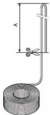
8.5.3 Replacing the cutting line head
- Type I
Follow the sequence shown in (Fig. 28).
- Type II
Cut the new line to the indicated length (Fig. 29.A).
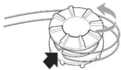
- Rotate the winding knob (Fig. 30.A) to align the reference on the knob (Fig. 30.B) with the reference on the head body (Fig. 30.C).
- Insert one end of the line (Fig. 30.D) in one of the two output holes and pass the line through the opposite hole.
- Align the lines that exit the two holes evenly.
- Rotate the winding knob (Fig. 31.A) following the direction of the arrows to wind the line, being careful to leave about 175 mm from both holes (Fig. 31.B).
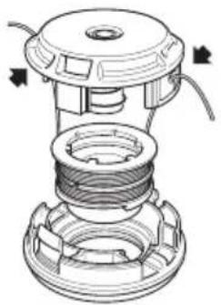
If old line is left in the head or if broken inside it, remove as described below:
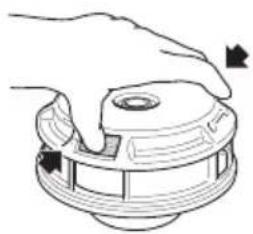
- press the tabs on the sides of the cutting line head, where marked "PUSH" (Fig. 32.A), and detach the lower part of the head (Fig. 32.B);
- Remove the line left inside;
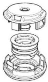
- replace the reel (Fig. 33.A) in its housing;
- close the head by fastening the tabs (Fig. 33.B) in the slots (Fig. 33.C), pushing them fully in until they click to lock the bottom part of the head (Fig. 33.D) in place.
8.6 SHARPENING THE WIRE CUTTING BLADE
- Remove the wire cutter blade (Fig.27.A) from the guard (Fig.27.B) by unscrewing the screw (Fig. 27.C).
- Secure the wire cutting blade in a vice (Fig. 27.A) and sharpen it using a flat file, being careful to retain the original cutting angle;
- Refit the wire cutter blade (Fig.27.A) on the guard (Fig. 27.B).
8.7 ADJUSTING IDLE SPEED
⚠️ If the cutting means moves with the engine idling, contact your dealer for the correct motor adjustment:
8.8 CARBURETTOR
The carburettor is set in the factory to obtain maximum performance in every use situation, with minimal emission of harmful gases, in compliance with current regulations.
In the event of poor performance, contact your Authorised Service for a carburettor and engine check.
9. STORAGE
IMPORTANT The safety regulations to follow for putting into storage are described in paragraph 2.4. Strictly comply with these instructions to avoid serious risks or hazards.
When the machine must be stored for a period of more than 2-3 months, certain steps must be taken to avoid difficulties when resuming work or permanent damage to the engine. Before storing the machine:
- Empty the fuel tank outdoors and when the engine is cold.
- Start the engine and leave it running at idle until it stops in order to consume all the fuel left in the carburettor.
- Wait for the engine to cool.
- Remove the spark plug cap (Fig. 14.H)
- Clean the machine thoroughly.
-
Check the machine for any damage. If necessary, contact the authorised service centre.
-
Store the machine:
– in a dry place;
– protected from inclement weather;
– with the blade guard correctly mounted;
– in a place out of children's reach;
– making sure that keys or tools used for maintenance are removed.
When starting up the machine again, prepare the machine as indicated in section 6 "Using the machine".
10. HANDLING AND TRANSPORT
When handling or transporting the machine, always:
- Stop the machine.
- Remove the spark plug cap (Fig. 14.H)
– Wear heavy-duty work gloves.
- When the cutting means has halted, fit the blade guard;
- Only hold the machine using the hand grips and position the cutting means in the opposite direction to that used during operations.
When transporting the machine on a vehicle, always:
- position it so that it does not cause a hazard to anyone;
– fasten firmly to the device of transport using ropes or chains to prevent it from tipping over causing damage and fuel leaks.
11. ASSISTANCE AND REPAIRS
This manual provides all the necessary information to run the machine and for correct basic maintenance operations which can be performed by the user. Any regulations and maintenance operations not described herein must be carried out by your Dealer or Authorised Service Centre, which have the necessary knowledge and equipment to ensure that the work is carried out correctly, maintaining the correct degree of safety and the original operating conditions of the machine. Any operations performed in unauthorised centres or by unqualified persons will totally invalidate the Warranty and all obligations and responsibilities of the Manufacturer.
- Only Authorised Service Centres can carry out guaranteed repairs and maintenance.
- The Authorised Service Centres only use genuine spare parts. Genuine spare parts and attachments have been designed specifically for machines.
- Non-genuine spare parts and accessories are not approved. Use of non-genuine spare parts and accessories cause the warranty to be voided.
- It is advisable to send your machine once a year to an Authorised Service Centre for servicing, assistance and safety device inspection.
12. WARRANTY COVERAGE
The warranty covers all material and manufacturing defects. The user must follow all the instructions provided in the accompanying documentation.
The warranty does not cover damage caused by:
- Failure to become familiar with the documentation accompanying the machine.
- Carelessness.
- Incorrect or prohibited use or assembly.
- Use of non-genuine spare parts.
- Use of attachments not supplied or not approved by the manufacturer.
The warranty does not cover:
- Normal wear and tear of consumables, such as cutting means, safety bolts.
• Normal wear and tear.
The purchaser is protected by his or her own national legislation. The purchaser's rights under the national laws or his or her own country are not in any way restricted by this warranty.
- MAINTENANCE TABLE
| Frequency | Intervention | |||||||||||||
| MACHINE ENGINE | ||||||||||||||
| Check all fasteners (see chap. 7.5) | Safety checks/ Controls verification (see chap. 6.2) | General cleaning and verification (see chap. 7.4) | Angle transmission and flexible drive-shaft lubrication (see chap. 8.1, 8.2) | Fuel level check/ top-up (see chap. 7.3) | General cleaning and verification (see chap. 7.4) | Air filter cleaning (see chap. 8.3) | Air filter replacement (see chap. 8.3) | Spark plug cleaning (see chap. 8.4) | Spark plug replacement (see chap. 8.4) | Tightening of the muffler screws * | Fuel filter replacement * | Cylinder exhaust port and cylinder wings* cleaning | ||
| Before each use | √ √ | √ √ | √ | |||||||||||
| 15 hours | √ | |||||||||||||
| 30 hours | √ √ | √ √ | ||||||||||||
| 45 hours | √ √ | √ | ||||||||||||
| 60 hours | √ √ | √ | ||||||||||||
| 75 hours | √ √ | √ | ||||||||||||
| 90 hours | √ √ | √ | ||||||||||||
| 105 hours | √ √ | √ √ | √ √ | |||||||||||
| 120 hours | √ √ | √ | ||||||||||||
| 135 hours | √ √ | √ | ||||||||||||
| 150 hours | √ √ | √ √ | ||||||||||||
| 165 hours | √ √ | √ | ||||||||||||
| 180 hours | √ √ | √ | ||||||||||||
| 195 hours | √ √ | √ | ||||||||||||
| 210 hours | √ √ | √ √ | √ √ | |||||||||||
| 225 hours | √ √ | √ | ||||||||||||
| 240 hours | √ √ | √ | ||||||||||||
| 255 hours | √ √ | √ √ | ||||||||||||
| 270 hours | √ √ | √ | ||||||||||||
| 280 hours | √ √ | √ | ||||||||||||
| 300 hours | √ √ | √ | ||||||||||||
* Interventions that must be carried out by your Dealer or by an Authorised Service Centre
14. TROUBLESHOOTING
| PROBLEM PROBABLE CAUSE SOLUTION | ||
| 1. The engine does not start or does not keep running | Incorrect starting procedure Follow the instructions (see Section 6.3) | |
| Dirty spark plug or incorrect electrode gap | Check the spark plug (see section 8.4). | |
| Clogged air filter Clean and/or replace the filter (see section 8.3). | ||
| Carburation fault Contact your Authorised Service Centre | ||
| 2. The engine starts but has little power. | Clogged air filter Clean and/or replace the filter (see section 8.3). | |
| Carburation fault Contact your Authorised Service Centre | ||
| 3. The engine has irregular operation or has no power under load | Dirty spark plug or incorrect electrode gap | Check the spark plug (see section 8.4). |
| Carburation fault Contact your Authorised Service Centre | ||
| 4. The engine causes excessive fumes | Incorrect composition of the fuel blend prepare the fuel blend in accordance with the instructions (see section 7.2) | |
| Carburation fault Contact your Authorised Service Centre | ||
| 5. Engine flooding The starter knob was operated repeatedly with the starter inserted, | Remove the spark plug (Fig. 26) and gently pull the starter rope knob (Fig. 14.I) to eliminate excess fuel; then dry the spark plug electrodes and reassemble on the engine. | |
| 6. The cutting means moves when the engine is idling | Incorrect adjustment of carburation | Contact your Authorised Service Centre |
| 7. Unusual machine vibrations | Damaged or loose parts. Stop the machine and disconnect the spark plug cable (Fig. 14.H.), inspect for possible damage. Check for and tighten any loose parts. All checks, replacements or repairs should be carried out by your authorised service centre. | |
| 8. The machine has struck a foreign body | Damaged or loose parts. Stop the machine and disconnect the spark plug cable (Fig. 14.H.), inspect for possible damage. Check for and tighten any loose parts. All checks, replacements or repairs should be carried out by your authorised service centre. | |
If problems persist after implementing the solution, contact your Dealer.
ÍNDICE
1.1 KUIDAS KASUTUSJUHENDIT LUGEDA
- SÄÄNNÖLLINEN HUOLTO....13
- YLIMÄÄRÄINEN HUOLTO....14
7.2 POLTTOAINESEOKSEN VALMISTUS
10. MANUTENTION ET TRANSPORT
7. PLĀNOTĀ TEHNISKĀ APKOPE
7.1 VISPĀRĒJA INFORMĀCIJA
2.5 BESCHERMING VAN DE OMGEVING
5.7 DISPLAY (INDIEN AANWEZIG)
7.5 MOEREN EN SCHROEVEN VOOR BEVESTIGING
- GENERELT....1
- SIKKERHETSBESTEMMELSER....2
- BLI KJENT MED MASKINEN....4
- ORDINÆRT VEDLIKEHOLD 12
- EKSTRAORDINÆRT VEDLIKEHOLD ...... 14
2.4 VEDLIKEHOLD, LAGRING OG TRANSPORT
3. BLI KJENT MED MASKINEN
3.1 BESKRIVELSE AV MASKINEN OG BEREGNET BRUK
Denne maskinen er et hageredskap, nærmere bestemt en bærbar trimmer/kantklipper med forbrenningsmotor til hobbybruk.
7. ORDINÆRT VEDLIKEHOLD
7.1 GENERELT
7.3 ETTERFYLLING AV DRIVSTOFF
Før etterfylling:
- rist kannen med drivstoffblandingen godt;
- sett maskinen i en stabil posisjon på et flatt underlag og med tanklokket vendt oppover (Fig. 14.G).
6.1 CZYNNOŚCI WSTĘPNE
5.7 DISPLAY (SE PRESENTE)
5.7 DISPLEJ (AK JE SÚČASŤOU)
Na displeji (obr. 14.J) sa zobrazujú informácie o činnosti a údržbe stroja.

Otáčkomer
6.4 PRACOVNÁ ČINNOSŤ
INNEHÅLLSFÖRTECKNING
5.4 HANDTAG FÖR MANUELL START
8.2 SMÖRJNING AV DEN FLEXIBLA AXELN
BC 636, BC 636 D, BC 536, BC 536 D
d) Motore
a scoppio
D. Lgs. 262/2002, ANNEX V (Italy)
BC 646, BC 646 D, BC 646 DX, BC 646 F, BC 546, BC 546 D
d) Motore
a scoppio
BC 546 D, BC 646 D, BC 646 DX
BC 646 F
BC 656, BC 656 D, BC 656 DX, BC 556, BC 556 D
d) Motore
a scoppio
EN • The content and images in this User Manual were produced expressly for ST. S.p.A. and are protected by copyright – any unauthorised reproduction or modification to the document, either partially or in full, is prohibited.
text_image
Scanned text of Chinese document with dense vertical columns and redacted sectionsType:
Art.N -s/n

text_image
LWA dBCE