USER MANUAL G 600 STIGA
natural_image
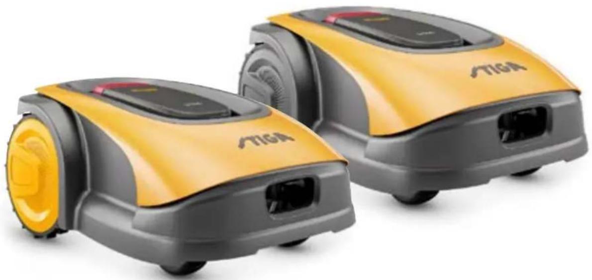
Two yellow and gray TIGA robotic vacuum cleaner units (no visible text or symbols)
STIGA
G 300
G 600
G 1200
EN Instruction manual
natural_image
Two yellow and gray StiGA robotic vacuum cleaner units (no visible text or symbols)
ENGLISH - TRANSLATION OF THE ORIGINAL INSTRUCTIONS
TABLE OF CONTENTS
1. MODELS TECHNICAL DATA 1
1.1. MODELS....1
1.2. TECHNICAL DATA 2
2. SAFETY 3
2.1. SAFETY INFORMATION ......
3
2.2. SAFETY INSTRUCTIONS .... 5
2.2.1. SAFE OPERATING PROCEDURES....5
2.2.2. FUNCTIONS ....5
2.3. STOPPING AND TURNING OFF THE ROBOT LAWN MOWER IN SAFE CONDITIONS....7
3. INTRODUCTION 8
3.1. GENERAL INTRODUCTION 8
3.1.1. PURPOSE OF THE MANUAL....8
3.1.2. INSTRUCTIONS ON READING FROM SMARTPHONES 8
3.2. PRODUCT OVERVIEW....9
3.2.1. GENERAL DESCRIPTION 9
3.2.2. MAIN COMPONENTS 10
3.3. UNPACKING....11
3.4. SYMBOLS AND NAMEPLATES....12
3.5. GENERAL INSTRUCTIONS ON HOW TO READ THE MANUAL....13
4. INSTALLATION 14
4.1. GENERAL INFORMATION FOR INSTALLATION....14
4.2. INSTALLATION COMPONENTS....14
4.3. INSTALLATION REQUIREMENTS CHECK....15
4.3.1. GARDEN ASSESSMENT: 15
4.3.2. CHECKS FOR THE INSTALLATION OF THE DOCKING STATION AND POWER SUPPLY: 15
4.3.3. MAIN VERIFICATIONS FOR THE INSTALLATION OF THE PERIMETER CABLE: 17
4.4. CRITERIA FOR INSTALLING THE PERIMETER CABLE....19
4.4.1. PERIMETER CABLE PLACEMENT 19
4.4.2. OBSTACLES DELIMITATION: 21
4.4.3. WALKWAYS FROM ONE AREA OF THE GARDEN TO ANOTHER 23
4.5. COMPONENTS INSTALLATION....23
4.5.1. INSTALLATION OF THE PERIMETER CABLE 24
4.5.2. SPLICING THE PERIMETER CABLE.... 25
4.5.3. DOCKING STATION INSTALLATION....26
4.5.4. RESISTOR INSTALLATION FOR SMALL PERIMETERS.... 28
4.6. CHARGE ROBOT LAWN MOWER AFTER INSTALLATION 29
4.7. PRODUCT SETTINGS....30
5. FUNCTIONS 35
5.1. SAFETY DEVICES CHECK FOR STARTING THE ROBOT LAWN MOWER 35
5.2. MANUAL FUNCTIONING OF THE ROBOT LAWN MOWER....36
5.3. CONTROLS DESCRIPTION ON THE ROBOT LAWN MOWER....37
5.3.1. SAFE STOP - STOP BUTTON 37
5.3.2. SAFE SHUTDOWN - SAFETY KEY 38
5.3.3. SWITCHING ON AND OFF - ON/OFF BUTTON 38
5.3.4. SCHEDULED PROGRAM / SINGLE WORK CYCLE SELECTION - SCHEDULED PROGRAM BUTTON ..... 39
5.3.5. BLUETOOTH STATUS DISPLAY AND UNPAIRING- BLUETOOTH BUTTON 41
5.3.6. ALARM STATUS DISPLAY - ALARM ICON 41
5.3.7. BATTERY CHARGE LEVEL DISPLAY-BATTERY ICON 42
5.3.8. STARTING THE ROBOT LAWN MOWER - START BUTTON 42
5.4. FUNCTIONING OF THE DOCKING STATION 43
5.5. BATTERY CHARGING 43
5.6. CUTTING HEIGHT ADJUSTMENT 44
6. MAINTENANCE 45
6.1. SCHEDULED MAINTANANCE 45
6.2. PRODUCT CLEANING....46
6.3. CUTTING BLADES REPLACEMENT 48
6.4. WINTER BATTERY MAINTENANCE AND STORAGE 49
6.5. BATTERY REPLACEMENT 49
7. TROUBLESHOOTING 50
7.1. MAIN MESSAGES FROM THE APP....51
8. TRANSPORT, STORAGE AND DISPOSAL 53
8.1. TRANSPORT 53
8.2.STORAGE....53
8.3. DISPOSAL....53
9. ACCESSORIES 54
- WARRANTY 55
- EC DECLARATION OF CONFORMITY 56
1. MODELS AND TECHNICAL DATA
1.1. MODELS
This manual refers to the models G 300, G 600, G 1200.
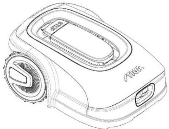
natural_image
Line drawing of a TiGA robotic vacuum cleaner (no text or symbols on body)

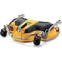
natural_image
Technical line drawing of a tracked robotic vehicle showing internal components and mounting hardware (no text or symbols)
1.2. TECHNICAL DATA
| SPECIFICATIONS | UNIT OF MEASURE | STIGA G 300 STIGA G 600 STIGA G 1200 |
| Dimensions (WxHxD) | [mm] 413 | x 252 x 560 413 x 252 x | 560 413 x 252 x 560 | |
| Weight of the robot lawn mower | [kg] 7.4 7 | 6 8 | | |
| Cutting height (Min-Max) | [mm] 20-60 | 20-60 20-60 | | |
| Blade diameter | [mm] | 180 | 180 | 180 |
| Cutting speed | [rpm] | 2850+/-50 | 2850+/-50 | 2850+/-50 |
| Speed of movement | [m/min] | 22 | 22 | 22 |
| Maximum slope | % | 45 | 45 | 45 |
| Maximum slope along the perimeter | % | 20 | 20 | 20 |
| Type of electric traction motor | - | Brushless | Brushless | Brushless |
| Type of cutting system | - | 4 pivoting cutting blades | 4 pivoting cutting blades | 4 pivoting cutting blades |
| Cutting device code | - | 322104105/0 | 322104105/0 | 322104105/0 |
| Type of electric cutting motor | - | Brushless | Brushless | Brushless |
| Sound power level detected | [dB] (A) | 57 | 57 | 57 |
| Uncertainty of noise emissions, KWA | [dB] (A) | 1.47 | 1.47 | 1.47 |
| Sound power level guaranteed | [dB] (A) | 59 | 59 | 59 |
| Acoustic level audible by the operator | [dB] (A) | 46.3 | 46.3 | 46.3 |
| IP rating of the robot lawn mower | - | IPX5 | IPX5 | IPX5 |
| IP rating of the charging station | - | IPX1 | IPX1 | IPX1 |
| IP rating of the power supply | - | IP67 | IP67 | IP67 |
| Robot lawn mower operating ambient temperature [°C] | [°C] | 0 ÷ 50 | 0 ÷ 50 | 0 ÷ 50 |
| Charging station operating ambient temperature [°C] | [°C] | -10 ÷ 50 | -10 ÷ 50 | -10 ÷ 50 |
| Power supply ambient operating temperature [°C] | [°C] | -10 ÷ 50 | -10 ÷ 50 | -10 ÷ 40 |
| Work capacity | [m2] | 300 | 600 | 1200 |
| Power supply | - | Input:100-240Vca; 1,2AOutput:30Vcc; 2A | Input:100-240Vca; 1,2AOutput:30Vcc; 2A | Input:100-240Vca; 1,2AOutput:30Vcc; 2A |
| Battery model | - | 25.2 - 25.9 V2 Ah | 25.2 - 25.9 V2.5 Ah | 25.2 - 25.9 V5 Ah |
| Charging time | [min] | 60 | 80 | 150 |
| Bluetooth | - | 4,2 4,2 | 4,2 | |
2. SAFETY
In the design of the device, special attention has been paid to aspects that can cause risks to the safety and health of people. The purpose of this information is to sensitize users to prevent any risk, avoiding behaviours that do not comply with the regulations reported.

DANGER:
Before using the robot lawn mower you must know all the information contained in this document.

DANGER:
This robot lawn mower is not intended to be used by children and people with reduced physical, sensory or mental abilities or with lack of experience and knowledge.
ELECTRICAL HAZARD:
Before carrying out any adjustment or maintenance intervention, disconnect the power supply and activate the safety device.
ELECTRICAL HAZARD:
Do not use the robot lawn mower with a damaged transformer power cable. A damaged cable can lead to contact with live parts. The cable must be replaced by the manufacturer or its assistance service or by a person with adequate qualifications, in order to prevent any risk.
ELECTRICAL HAZARD:
Only use the battery charger and power supply provided by the manufacturer. The use of an inappropriate charger and power supply can cause electric shocks and / or overheating.

CAUTION:
In case of leakage of liquid from the battery, the affected components must be washed with water / neutralizer.
Avoid any direct contact with the battery liquid.
If the liquid comes into contact with the eyes, call a doctor immediately.

CAUTION:
During the operation of the robot lawn mower, make sure that there are no people, especially children, or\and pets, in the operating area. Otherwise, program the activity of the robot lawn mower during the hours when there are no people in that area.

CAUTION:
The operational area must be limited by a non-passable fence.
Make the fence suitable or supervise the robot lawn mower during its operation.

CAUTION:
Only use original spare parts.
STIGA
CAUTION:
Do not modify, tamper with, elude or eliminate the safety devices installed.

WARNING:
Check that there are no toys, tools, branches, clothing, or other items on the lawn that could damage the device.

BAN:
Do not sit on top of the robot lawn mower.

BAN:
Never lift the robot lawn mower to inspect the blade or to transport it when it's started. Do not put your hands and feet under the device.

BAN:
Do not use the robot lawn mower when a sprinkler is in operation.

BAN:
Do not wash the robot lawn mower with high pressure water jets, and do not immerse it, partially or completely, in water.

BAN:
Do not use the robot lawn mower if it is not perfectly intact in all its parts. In case of damage replace the affected parts.

BAN:
It is absolutely forbidden to use and recharge the robot lawn mower in explosive and inflammable environments.

OBLIGATION:
Visually check the robot lawn mower at regular intervals to make sure the blades and mowing mechanism are not worn out or damaged. Make sure that the robot lawn mower is in good operating conditions.

OBLIGATION:
Read the entire manual carefully, especially all safety information, and make sure you fully understand it. Follow the operating, maintenance and repair instructions carefully.

OBLIGATION:
Operators carrying out maintenance and repair interventions must be utterly familiar with the specific features and safety regulations of the robot lawn mower.

GLOVES OBLIGATION:
Use personal protection foreseen by the Manufacturer. Always use protective gloves when working on the cutting mechanism.
2.2. SAFETY INSTRUCTIONS

OBLIGATION:
Read carefully before use and store for future reference.
2.2.1. SAFE OPERATING PROCEDURES
Training
a. Read the instructions carefully, learn the controls and the correct use of the machine.
b. Never allow children, persons with reduced physical, sensory or mental capabilities, or lack of experience and knowledge, or persons unfamiliar with these instructions, to operate the machine. Local regulations may limit the age of the operator.
c. The operator, or user, is to be held responsible for accidents or hazards involving third parties or third party equipment.
Preparation
a. Make sure that the automatic system of perimeter delimitation is installed correctly as indicated.
b. Periodically check the area where the machine is used and remove stones, sticks, cables and any other foreign objects that may interfere with its operation.
c. Periodically carry out a visual inspection of the blades, blade bolts and of the cutting unit to check that they are not worn out or damaged. Replace worn out or damaged blades and bolts in pairs to maintain the balance of the machine.
d. Warning signs must be placed around the working area of the machine if it is used in public areas or areas open to the public. Signs must read as follows: "Warning! Automatic lawn mower! Keep away from the machine! Children must be supervised!"
2.2.2. OPERATION
a. Do not operate the machine with defective guards or safety devices that are not present, for example without protections.
b. Do not put hands or feet near or under the rotating parts. Always keep away from the drain opening.
c. Do not touch any moving parts of the machine until they have come to a complete stop.
d. Always wear sturdy shoes and long trousers when operating the machine.
e. Never lift or transport the machine when the motor is running.
f. Remove the disabling device from the unit:
- Before removing an obstruction;
- Before checking, cleaning or working on the machine.
g. Do not leave the machine in operation unattended in the presence of pets, children or other people nearby.
Maintenance and storage
a. Tighten all nuts, bolts and screws securely for safe operation of the machine.
b. Frequently check the robot lawn mower for wear or deterioration.
c. For safety reasons it is necessary to replace worn out or damaged parts.
d. Make sure that the blades are replaced only with suitable spare parts.
e. Make sure the batteries are recharged using the correct charger recommended by the manufacturer. Incorrect use can cause electric shock, overheating or leakage of corrosive liquid from the battery.
f. In case of electrolyte leaks, wash with water / neutralizing agent and consult a doctor in case of contact with eyes, etc.
g. Machine maintenance must be carried out in accordance with the manufacturer's instructions.
Battery / battery charger

WARNING:
Lithium-ion batteries can explode or cause fires if disassembled, exposed to water, fire or high temperatures or in the event of a short circuit. Handle the battery carefully, do not disassemble it and avoid any type of improper electrical or mechanical stress. Avoid exposing the battery to direct sunlight.
NOTE: It is recommended to use only original products supplied by the manufacturer. Non-original or inadequate products can cause damage to the robot lawn mower or can be dangerous for people, animals and things.
a. The battery should only be installed and / or removed from the robot lawn mower by the retailer or a service centre.
b. Store the unused battery in a safe place away from sources of heat or objects that can cause short circuits (pegs, screws, metal objects of various kinds).
c. Use the battery charger away from flammable surfaces or substances, and in preferably dry places.
d. Transport the battery and the battery charger in the original packaging.
Environmental protection
NOTE: Safeguarding the environment must be a relevant and priority aspect of machine use, of benefit to the community and the environment we live in.
a. Dispose of packaging and damaged parts as required by local regulations in the country of use.
b. Dispose of electrical equipment (robot lawn mower, battery, power supplies, etc.) as per European Directive 2012/19 / EU and in compliance with the national standards. For further information on the disposal, contact your retailer or a domestic waste collection service.
c. Separate collection of products and packaging is recommended.
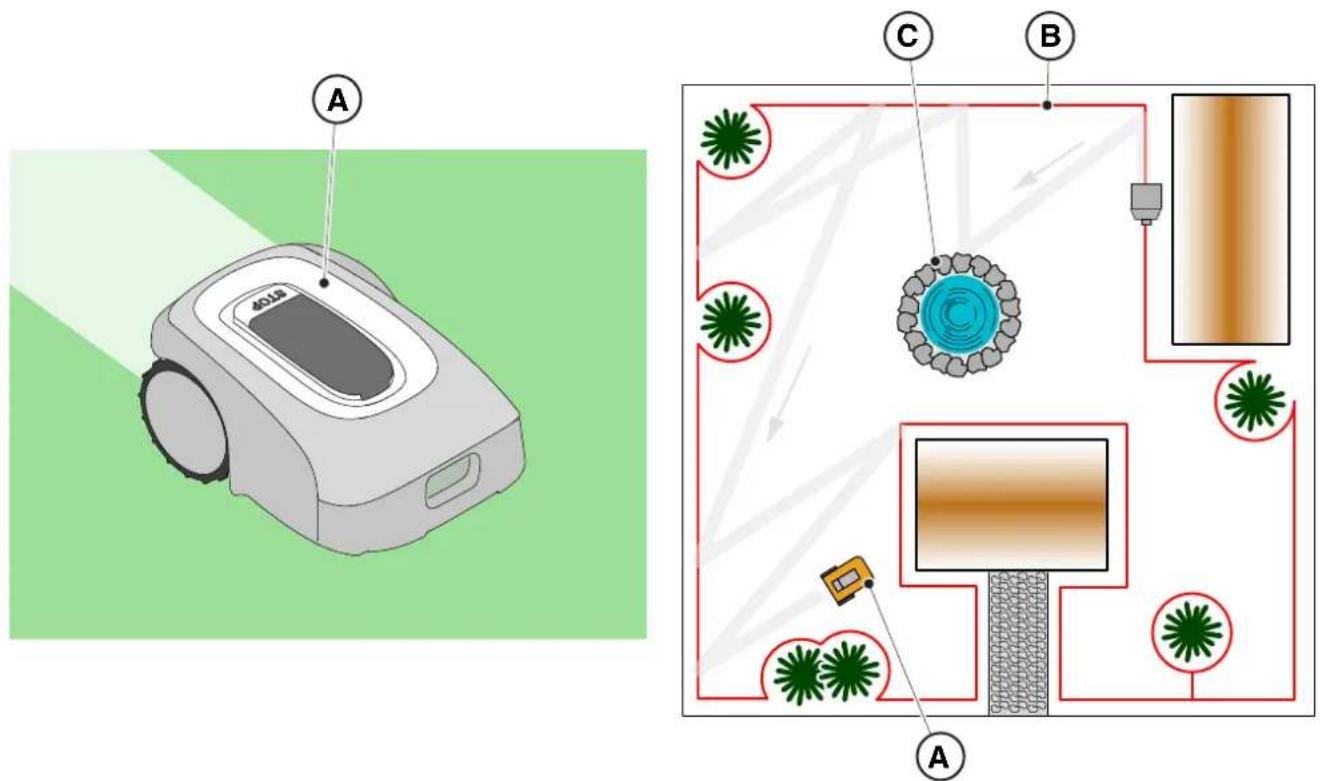
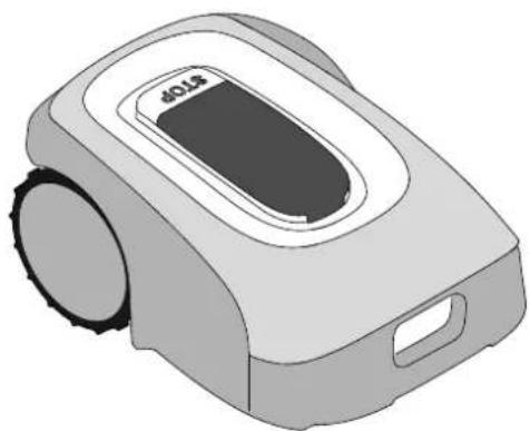
2.3. STOPPING AND TURNING OFF THE ROBOT LAWN MOWER IN SAFE CONDITIONS

OBLIGATION:
Always switch off the robot lawn mower in safe conditions before any cleaning, transport or maintenance operation.
Requirements and obligations:
- Safety key.
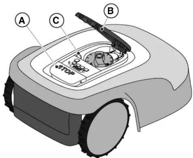
Procedure:
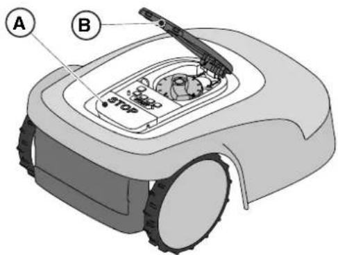
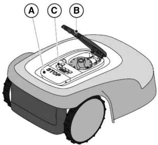
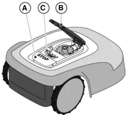
- Press the "STOP" (A) button to stop the robot lawn mower safely and open the protective cover (B).
- Disengage the safety key (C) to switch off the robot lawn mower in safe conditions.
- Close the protective cover (B).
- The robot lawn mower is stopped or switched off in a safe condition.
text_image
A
C
B
STOP
3. INTRODUCTION
3.1. GENERAL INTRODUCTION
3.1.1. PURPOSE OF THE MANUAL
This manual is an integral part of the device and it is intended to provide the information necessary for its use.
Keep this manual for the entire life of the device, so that it is always available in case of need.
The recipient of the manual is the user of the device, who is required to carefully read the information contained therein and apply it rigorously to protect people's safety and to avoid damage.
The information is drawn up in the original language of the manufacturer (Italian) and translated into any other languages for legislative and/or commercial needs.
The following symbols have been adopted to highlight important texts.
DANGER \ CAUTION \ WARNING:
The pictograms contained in a triangle with a yellow background and a black line indicate danger \ caution\ warning.
BAN:
The pictograms contained in a crossed-out circle with a white background and a red stroke indicate a ban.
OBLIGATION:
The pictograms contained in a circle with a blue background indicate an obligation.
NOTE: The texts shown in this form indicate technical information of particular importance, which should not be ignored.
3.1.2. INSTRUCTIONS FOR READING FROM SMARTPHONE
For better readability of the user manual, it is recommended to keep the smartphone in an horizontal position, as shown in the picture.
[1] Market exercise 1) A proposed a contract or space automaticamente
3.2. PRODUCT OVERVIEW
3.2.1. GENERAL DESCRIPTION
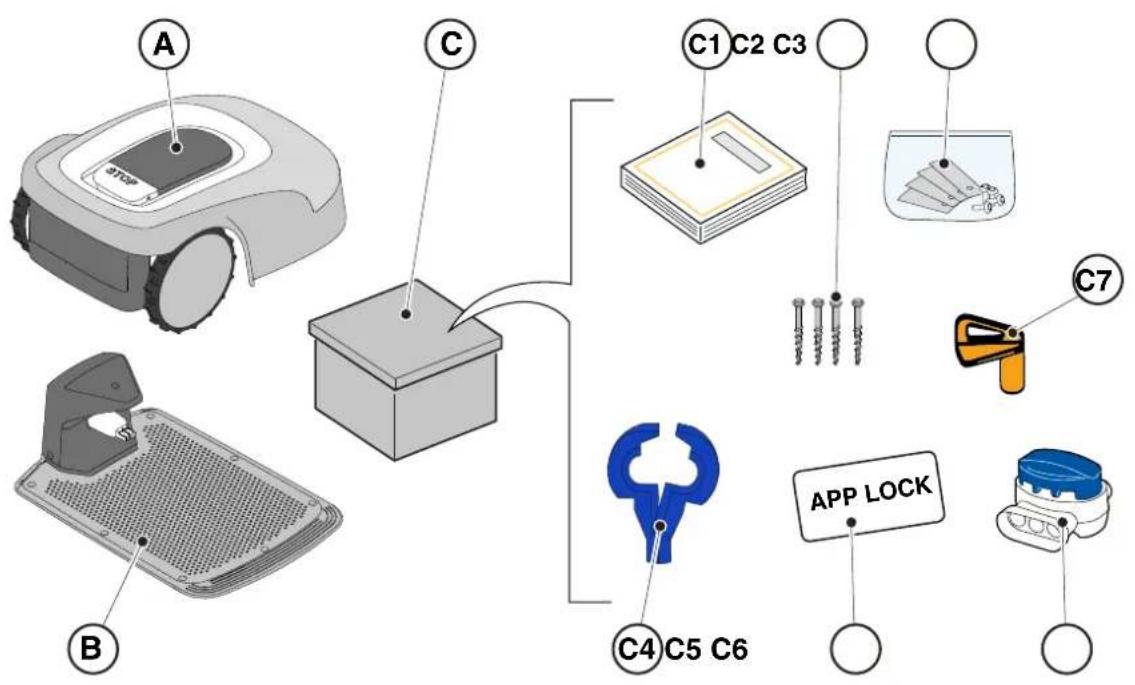
The robot lawn mower (A) is designed and built to automatically cut garden grass at any time of day and night.
According to the different characteristics of the surface to be cut, the lawnmower robot can be programmed to work on several areas delimited by the perimeter cable.
When operating, the robot lawn mower mows the area delimited by the perimeter cable (B).
When the robot lawn mower detects the perimeter cable (B) or encounters an obstacle (C) it changes trajectory randomly.
Based on the random operation principle, the robot lawn mower mows the delimited lawn automatically and completely.
Any other usage may be hazardous and harm persons and/or damage things. Improper use includes (for example, but not limited to): transporting people, children or animals on the machine; being transported by the machine; using the machine to pull or push loads; using the machine for cutting non-grass vegetation.
text_image
A
4018
C
B
A
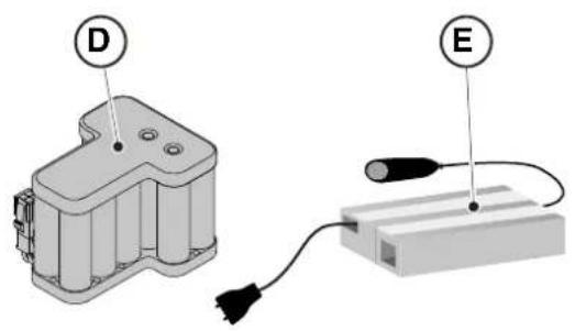
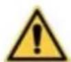
3.2.2. MAIN COMPONENTS
(A) Robot lawn mower
(B) Docking station
(C) Starter kit
(D) Battery (inside the robot lawn mower)
(E) Docking station power supply
(C1) Instruction manual
(C2) Docking station fixing screws
(C3) Blister with blades and fixing screws
(C4) Charging Base connectors
(C5) App Lock Label
(C6) Joint for perimeter cable
(C7) Safety key
text_image
A
B
C
C1 C2 C3
C4 C5 C6
C7
APP LOCK
natural_image
Technical diagram showing two components: a mechanical housing labeled D and a rectangular device labeled E connected by wires (no text or symbols beyond labels)
• Installation kit (Optional for G 600 and G 1200)
(F) Perimeter cable
(G) Perimeter cable fixing pegs
(H) joint for perimeter cable
(I) Docking station connectors
See Chapter 9 "Accessories"

text_image
Diagram showing four labeled components: coiled wire, test tube, cap, and plastic connector with letter indicators.
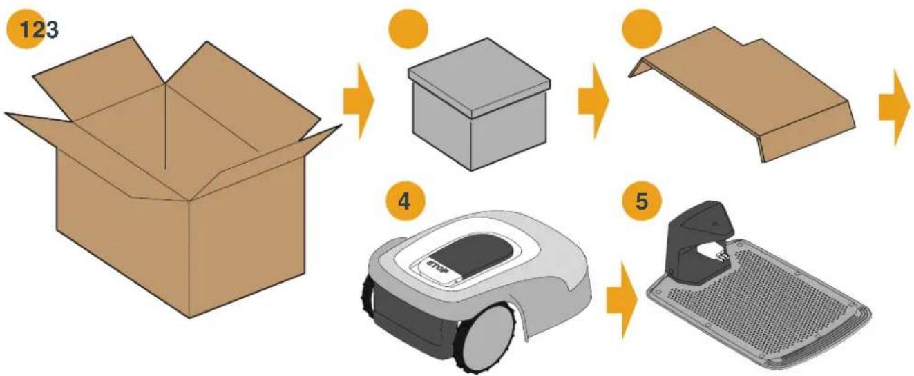
3.3. UNPACKING
Following are listed all the steps to perform the correct unpacking:
- Open the box of the robot lawn mower;
- Take out the "Starter Kit" box;
- Take out the upper containment carton;
- Take out the robot lawn mower;
- Take out the docking station.
WARNING:
Make sure to remove all packaging material from the robot lawn mower before using it.

WARNING:
To avoid injury or damage, please be careful when unpacking the robot lawn mower, avoiding contact with cutting blades or other hazardous elements.
flowchart
graph TD
    A["Open Box 123"] --> B["Box 4"]
    B --> C["Box 5"]
    C --> D["Robot Vacuum Cleaner"]
3.4. SYMBOLS AND NAMEPLATES
Below all the symbols on the robot lawn mower are listed:

text_image
Safety warning signs and a robotic device with Chinese labels, including warning symbols for accidents, vehicle accidents, and no-discrimination.

WARNING:
Read the user instructions before starting the product.

WARNING:
Danger of projections of objects against the body.
Keep an adequate safe distance from the machine while it is running.
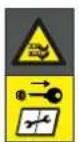
WARNING:
Do not put hands and feet near or under the opening of the cutting means.
Remove the disabling device before operating on the machine or before lifting it.
WARNING:
Do not put hands and feet near or under the opening of the cutting means.
Do not stand on the machine.

BAN:
Do not use high pressure cleaners on the machine to clean or wash it.

BAN:
Make sure that there are no people (especially children, elderly or disabled) and pets in the working area during the operation of the machine.
Keep children, pets and other people at a safe distance when the machine is functioning.
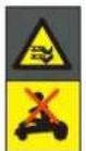
All the symbols on the Battery are shown below:
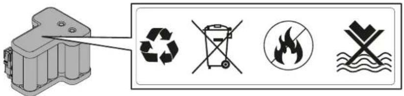
text_image
Diagram showing four types of waste management symbols: recycling, no litter, fire, and water discharge.

WARNING:
Read the user instructions before starting the product.
Do not dispose of the battery as normal household waste.
Dispose of the battery in the appropriate authorized collection centres.

Do not throw the battery into the fire and do not expose it to heat sources.

Do not immerse the battery in water and do not expose it to moisture.
3.5. GENERAL MANUAL READING INSTRUCTIONS
The criteria used for the preparation of this document are described below.
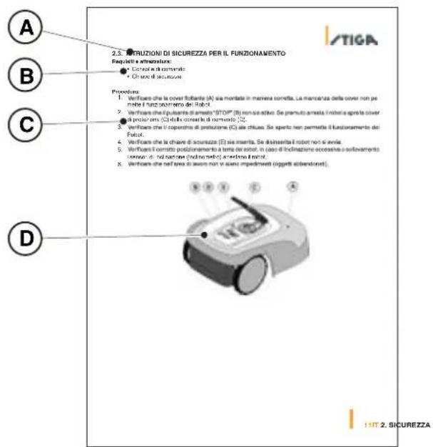
- Topic title (A)
- Requirements and equipment for carrying out the procedure (B)
- Description of the procedure (C)
- Descriptive pictures of the procedure (D)
- App section title (E)
- App navigation procedure (F)
Do not modify, tamper with, elude or eliminate the safety devices installed.
NOTE: For further clarification on the installation of the product please contact a STIGA dealer.
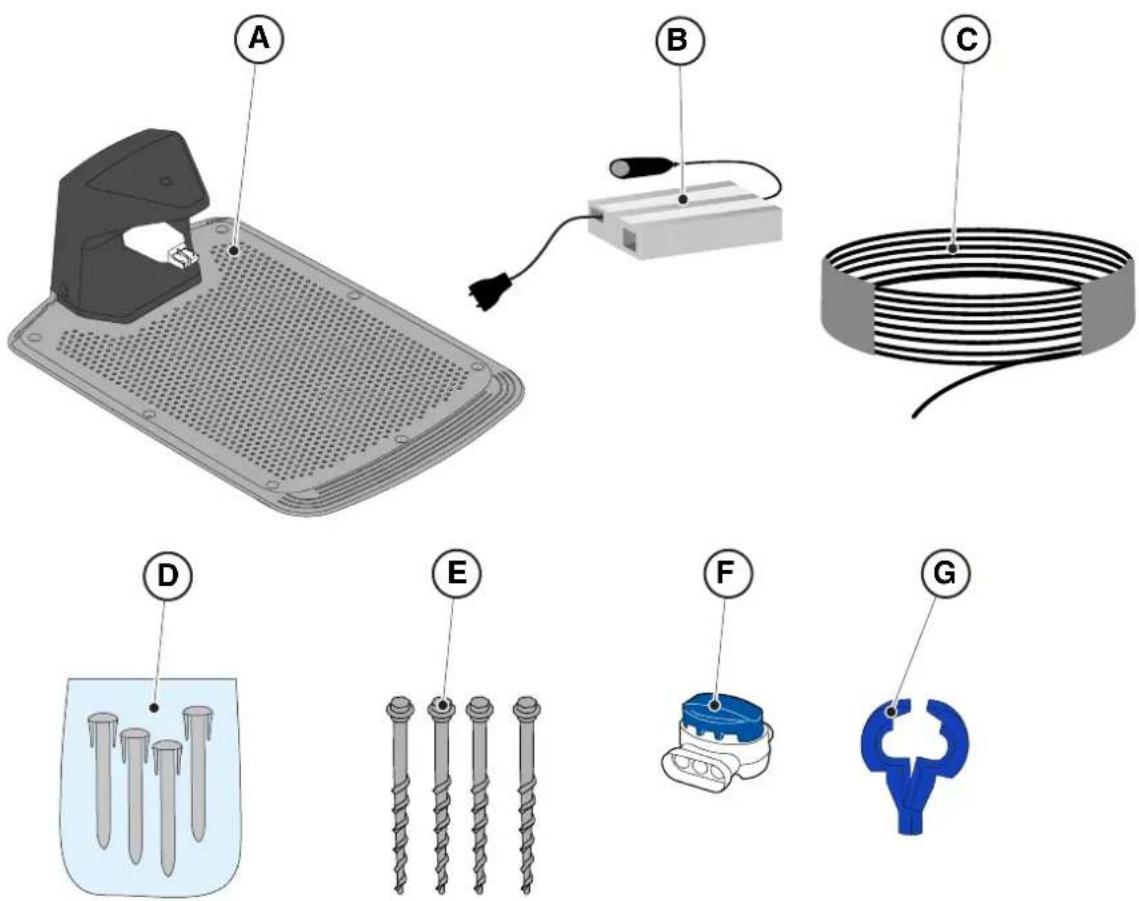
4.2. INSTALLATION COMPONENTS
(A) Docking Station
(B) Power supply
(C) Perimeter cable (included in the installation Kit)
(D) Perimeter cable fixing pegs (included in the installation Kit)
(E) Docking station fixing screws
(F) Joint for perimeter cable (included in the installation Kit)
(G) Docking station connectors (included in the installation kit)
See Chapter 9 "Accessories"
text_image
Diagram showing labeled components of a mechanical or electrical device, including a iron iron, cable, and screw assembly.
4.3. VERIFICATION OF THE INSTALLATION REQUIREMENTS
Below the procedures to check the necessary requirements and prepare the garden before proceeding with the installation are described.
4.3.1. GARDEN VERIFICATION:
- Carry out a survey of the entire area for a correct detection of the state of the garden, of any obstacles and areas to be excluded.
- Check that the lawn to be mowed is uniform, free of holes, stones or other obstacles and, if necessary, carry out the appropriate environmental decontamination works.
NOTE: Level the ground to prevent puddles from forming after a rainfall.
NOTE: At the first installation, the initial height of the grass must be within the operating range of the robot lawn mower: 20-60mm. If necessary, prepare the garden using a traditional lawn mower.
4.3.2. DOCKING STATION AND POWER SUPPLY INSTALLATION CHECKS
 | ELECTRICAL HAZARD:A socket must have been prepared near the installation area to connect it to electricity. Make sure that connection to the power supply network conforms to laws in force of the Country where it is used. |  | ELECTRICAL HAZARD:Do not connect the power supply to an electrical outlet if the plug or the cable is damaged.Do not connect or touch a damaged cable before it is disconnected from the power supply.A damaged cable can lead to contact with live parts. |
 | ELECTRICAL HAZARD:The circuit provided must be protected by a residual current device (RCD) with an activation current not exceeding 30 mA. | | |
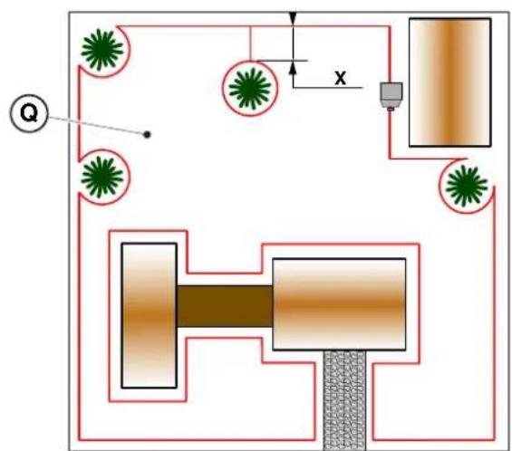
Procedure:
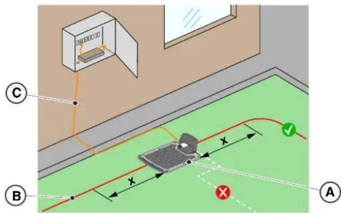
- Prepare a flat area at the edge of the lawn for positioning the docking station (A), preferably in the largest portion of the garden and near an electrical outlet.
- Make sure there is enough space to install the docking station on a straight section of the perimeter cable (B), so that the distance of the base from any curves is at least X = 200 cm ; the ground must be perfectly flat and compact in order to avoid the deformation of the surface of the docking station.
text_image
Diagram illustrating a mechanical or electrical setup with labeled components A, B, C and directional arrows indicating paths and distances.

WARNING:
The power cable (C), power supply unit, extension cord and all other electric cables which do not belong to the product must remain outside the cutting area to maintain their distance from hazardous moving parts and prevent damage to cables which may come into contact with live parts.
- Make sure that the area chosen for installing the docking station (D) is at least 400 cm away from the docking station (E) of a possible second robot lawn mower.
flowchart
graph TD
    A["Input"] --> B{Decision}
    B -->|Yes| C["Process 1"]
    B -->|No| D["Process 2"]
    C --> E["Output"]
    D --> E
    style A fill:#f9f,stroke:#333
    style E fill:#bbf,stroke:#333

WARNING:
The excessive proximity between two docking stations could cause interference (See Par. 4.7.14)
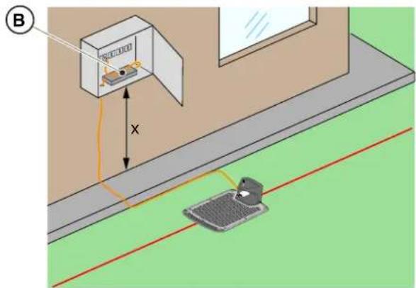
- Prepare the installation area of the power supply unit (B) so that it is protected from solar radiation and in order to prevent it from being submerged in water at any time.
NOTE: It is preferable and recommended to install the power supply (B) in a closed compartment protected from atmospheric agents, in a position that is not easily accessible by unauthorized persons such as children (X>160 cm).
text_image
Diagram showing a device mounted on a wall with a sensor, labeled with dimension 'X' and figure marker (B)
4.3.3. MAIN CHECKS WHEN INSTALLING THE PERIMETER CABLE:
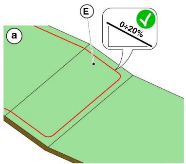
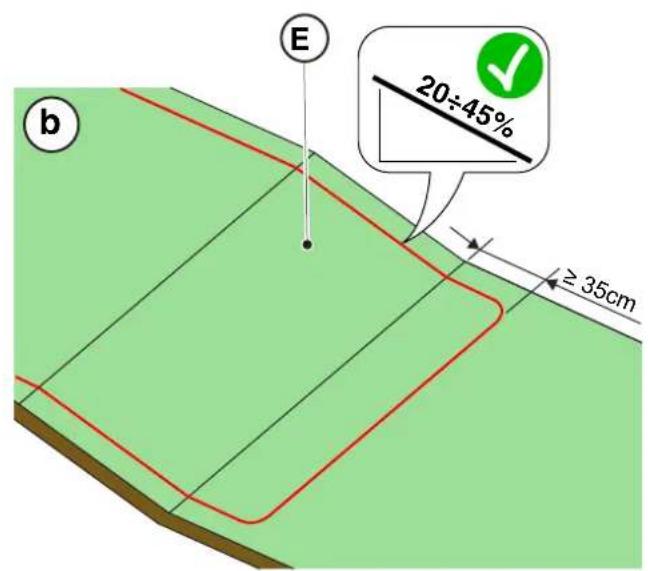
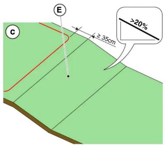
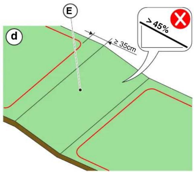
- Check that the maximum slope of the work area is less than or equal to 45 % (E) and observe the rules shown in the images below:
a) if the slope is ≤ 20% the perimeter cable can be installed on it as shown in the image;
b) if the slope is >20% and ≤45% , the installation must include the slope area observing the distance indicated in the image;
c) if the slope is >20% and the slope area is not part of the part of the garden to be cut, the distance indicated in the image must be observed;
d) if the slope is >45%, the slope area must be excluded observing the distance indicated in the image.
text_image
a
E
0÷20%
text_image
E
20÷45%
≥ 35cm
b
text_image
E
≥ 35cm
C
>20%
text_image
E
≥ 35cm
d
> 45%
STIGA

WARNING:
The robot can mow surfaces with a maximum slope of 45%.
In case of non-compliance with the instructions, the robot may slip and exit the work area

WARNING:
Areas with slopes higher than allowable slopes cannot be mowed. Then place the perimeter cable before the slope, excluding that area of lawn from the mowing.
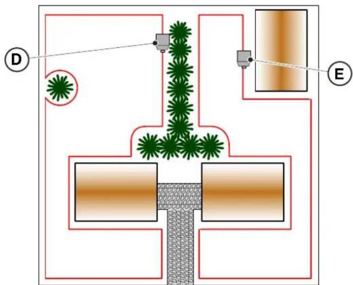
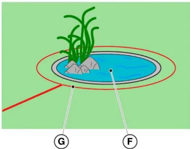
- Check the entire work surface: assess the obstacles and areas to be excluded from the work area (F), which must be delimited with the perimeter cable (G).
text_image
Diagram illustrating plant growth in a pond with labeled points G and F, showing green plants and water level.
4.4. CRITERIA FOR INSTALLING THE PERIMETER CABLE
4.4.1. PERIMETER CABLE PLACEMENT
Procedure:
-
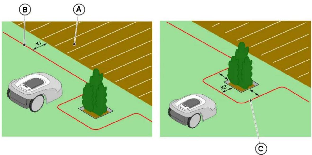
If there is a pavement or path (A) at the same level as the lawn, arrange the perimeter cable (B) at X1 = 5cm from the edge of the pavement.
-
In the vicinity of a level flower bed, a metal manhole, a shower surface or electrical cables, arrange the perimeter cable (C) at least X2 = 30 cm away.
text_image
A
B
X1
X2
C
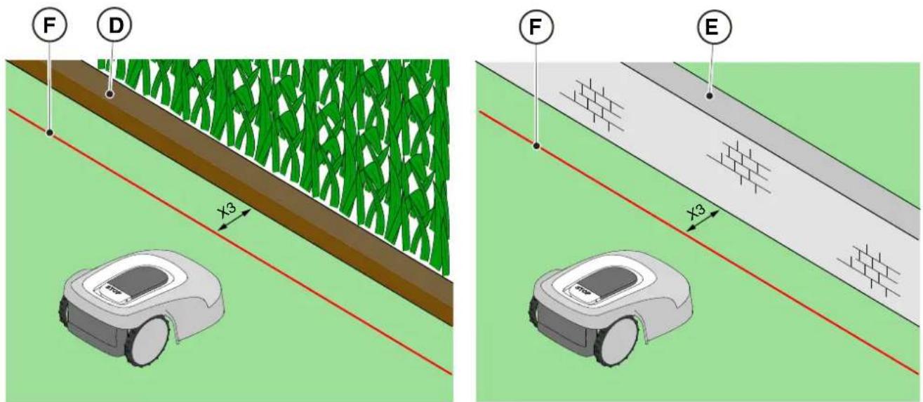
- If there is an obstacle, for example a ditch (D), a wall or a low wall (E), arrange the perimeter cable (F) at least X3 = 35 cm from the obstacle.
text_image
F
D
X3
F
E
X3
STIGA
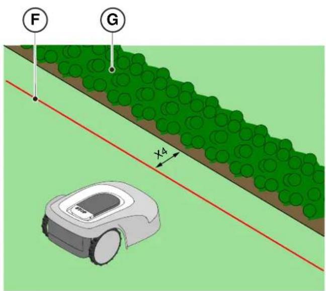
- If there is a hedge (G) or a plant with protruding roots (H), arrange the perimeter cable (F) at least X4 = 30 cm.
text_image
F
G
X4
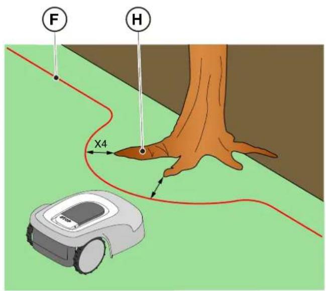
text_image
F
H
X4
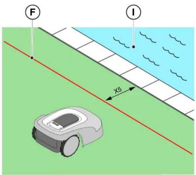
- If there is an infinity pool or pond (I), unsecured public roads (L), adjust the perimeter cable (F) at least X5 = 90 cm .
text_image
F
I
x5
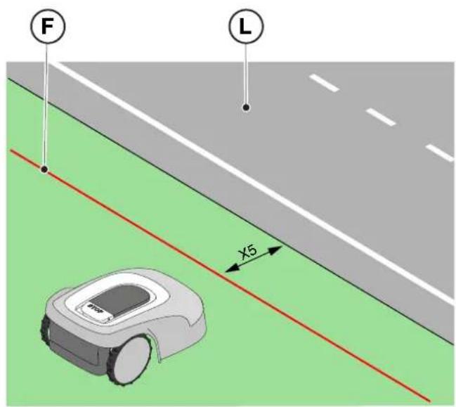
text_image
F
L
X5
- If there is a swimming pool (M) or a road (N) at the end of a slope (O), arrange the perimeter cable (P) at least X6 = 150 cm .

WARNING:
If the slope is greater than 45%, the slope area must be excluded from the cutting area (See Par. 4.3).
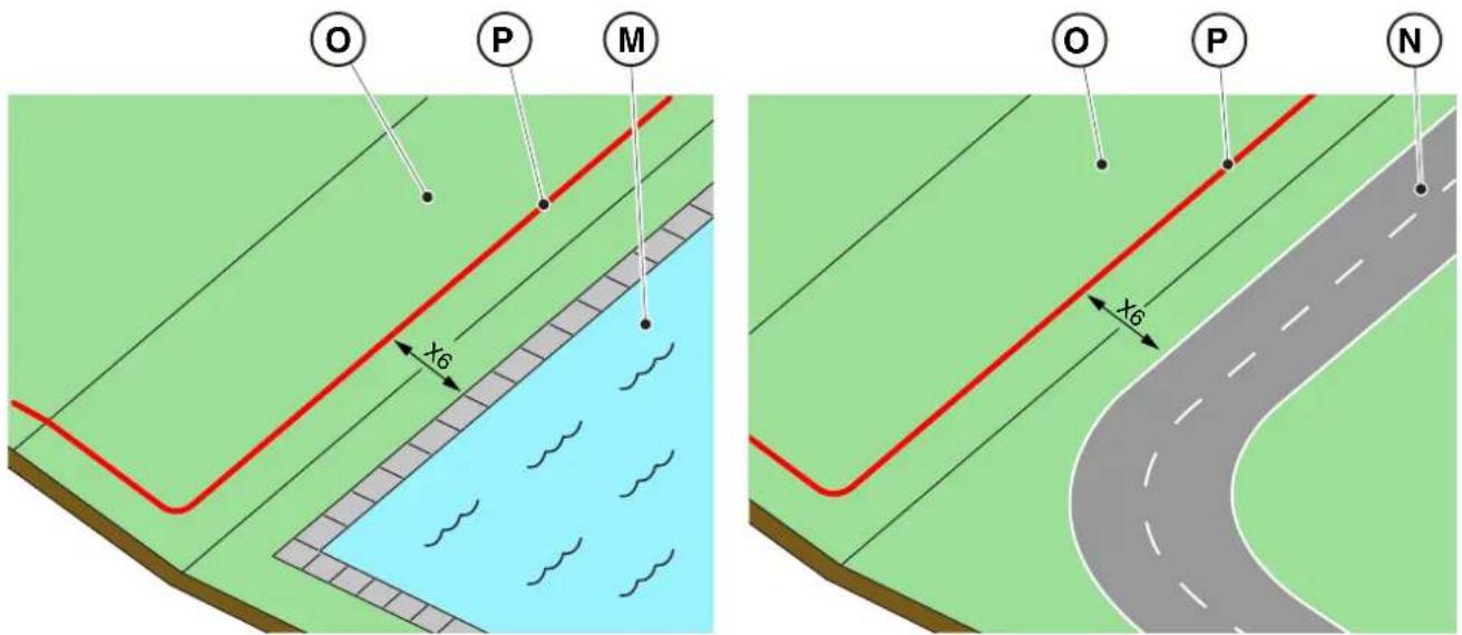
text_image
O
P
M
x6
O
P
N
x6

CAUTION:
The operational area must be limited by a non-passable fence. Make the fence suitable or supervise the robot lawn mower during its operation.
4.4.2. DELIMITATION OF OBSTACLES
Procedure:
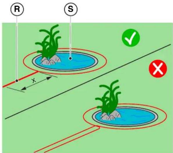
- If the minimum passage between two different sections of the perimeter cable is X ≥ 70 cm, the obstacle can be delimited as shown in the figure (Q), overlapping the sections of the outward and return cables without crossing them (R).
-
To delimit the obstacle (S):
-
Place the perimeter cable up to the obstacle and go around it;
- Bring the cable back along the previous path overlapping it under the same nail, without creating intersections (R).
flowchart
graph TD
    A["Valve"] --> B["Pump"]
    B --> C["Directional Flow Indicator X"]
    C --> D["Flow Indicator Q"]
    D --> E["Central Component"]
    E --> F["Bottom Component"]
    F --> G["Left Side"]
    F --> H["Right Side"]
    style A fill:#f9f,stroke:#333
    style B fill:#ccf,stroke:#333
    style C fill:#cfc,stroke:#333
    style D fill:#fcc,stroke:#333
    style E fill:#cff,stroke:#333
    style F fill:#ffc,stroke:#333
    style G fill:#fcf,stroke:#333
    style H fill:#cff,stroke:#333
text_image
R
S
x
NOTE: For the robot lawn mower's correct functioning, the minimum length of the superimposed perimeter cable (R) must be X = 70 cm.
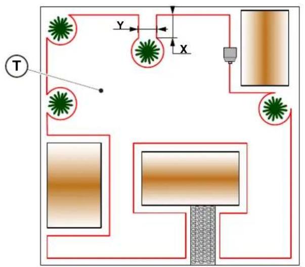
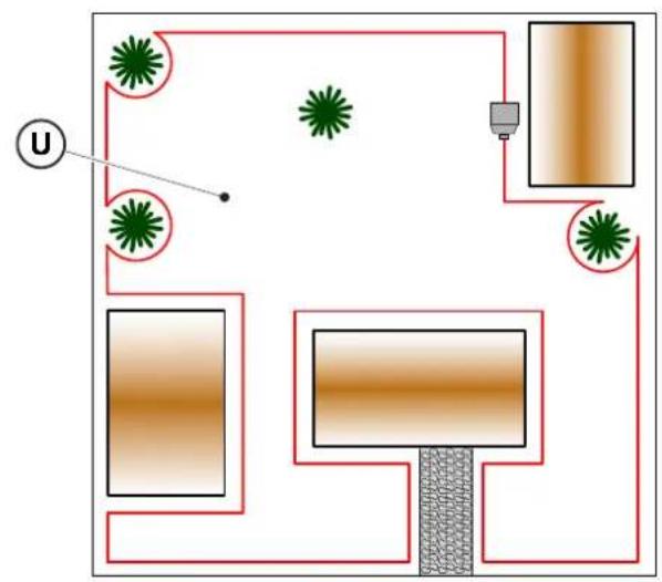
- If the minimum passage between two different sections of the perimeter cable is X <70 cm, the obstacle can be delimited by spacing the two sections of the outward and return cable by a height Y ≥30 cm as indicated in the figure (T), or, if the obstacle is strong enough, it can be left unprotected as shown in figure (U).
flowchart
graph TD
    A["Central Rectangle"] --> B["Sensor"]
    B --> C["Sensor"]
    C --> D["Sensor"]
    D --> E["Sensor"]
    E --> F["Sensor"]
    F --> G["Sensor"]
    G --> H["Sensor"]
    H --> I["Sensor"]
    I --> J["Sensor"]
    J --> K["Sensor"]
    K --> L["Sensor"]
    L --> M["Sensor"]
    M --> N["Sensor"]
    N --> O["Sensor"]
    O --> P["Sensor"]
    P --> Q["Sensor"]
    Q --> R["Sensor"]
    R --> S["Sensor"]
    S --> T["Sensor"]
    T --> U["Sensor"]
    U --> V["Sensor"]
    V --> W["Sensor"]
    W --> X["Sensor"]
    X --> Y["Sensor"]
    Y --> Z["Sensor"]
    Z --> A
    style A fill:#f9f,stroke:#333
    style B fill:#ccf,stroke:#333
    style C fill:#cfc,stroke:#333
    style D fill:#fcc,stroke:#333
    style E fill:#cff,stroke:#333
    style F fill:#ffc,stroke:#333
    style G fill:#cfc,stroke:#333
    style H fill:#fcc,stroke:#333
    style I fill:#ffc,stroke:#333
    style J fill:#cfc,stroke:#333
    style K fill:#fcc,stroke:#333
    style L fill:#ffc,stroke:#333
    style M fill:#cfc,stroke:#333
    style N fill:#fcc,stroke:#333
    style O fill:#ffc,stroke:#333
    style P fill:#cfc,stroke:#333
    style Q fill:#fcc,stroke:#333
    style R fill:#ffc,stroke:#333
    style S fill:#cfc,stroke:#333
    style T fill:#fcc,stroke:#333
    style U fill:#ffc,stroke:#333
    style V fill:#cfc,stroke:#333
    style W fill:#fcc,stroke:#333
flowchart
graph TD
    A["Central Structure"] --> B["Arrow to U"]
    B --> C["Star-like Elements"]
    C --> D["Arrow to Right"]
    D --> E["Arrow to Left"]
    E --> F["Arrow to Right"]
    F --> G["Arrow to Left"]
    G --> H["Arrow to Right"]
    H --> I["Arrow to Left"]
    I --> J["Arrow to Right"]
    J --> K["Arrow to Right"]
    K --> L["Arrow to Left"]
    L --> M["Arrow to Right"]
    M --> N["Arrow to Left"]
    N --> O["Arrow to Right"]
    O --> P["Arrow to Right"]
    P --> Q["Arrow to Left"]
    Q --> R["Arrow to Right"]
    R --> S["Arrow to Right"]
    S --> T["Arrow to Left"]
    T --> U["Arrow to Right"]
    U --> V["Arrow to Right"]
    V --> W["Arrow to Left"]
    W --> X["Arrow to Right"]
    X --> Y["Arrow to Right"]
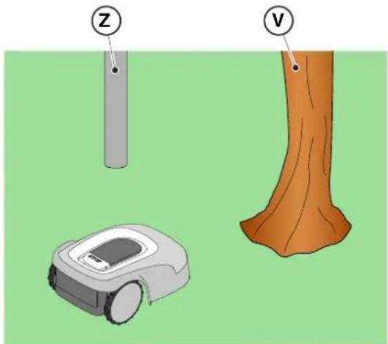
- In general, it is advisable to delimit obstacles, however if there are localized obstacles that resist impact, for example trees without protruding roots (V) or poles (Z), it is possible not to delimit them.
natural_image
Illustration of a robotic vacuum cleaner and tree trunk with labeled parts (Z and V), no text or symbols present.
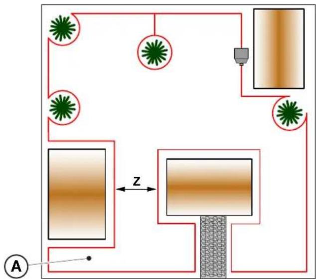
4.4.3. PASSAGES AMONG DIFFERENT AREAS OF THE GARDEN
Procedure:
- In the case of corridors, the distance between two different sections of the perimeter cable must be Z ≥ 70 cm.
- In case of passage between two different sections of cable Z <70 cm, the area (A) is to be considered a "Closed Area" and cannot be reached by the robot lawn mower automatically.
flowchart
graph TD
    A["Central Unit"] --> B["Processing Unit"]
    B --> C["Output Area"]
    style A fill:#f9f,stroke:#333
    style B fill:#bbf,stroke:#333
    style C fill:#dfd,stroke:#333
NOTE: For programming the robot lawn mower relating to the configuration of the garden with "Closed Area" please refer to the procedure at Par . 4.7.5 "Closed Area".
4.5. COMPONENTS INSTALLATION
 | ELECTRICAL HAZARD:Only use the battery charger and power supply provided by the manufacturer. Improper use may cause electric shock and/or overheating. |  | CAUTION:The circuit provided must be protected by a residual current device (RCD) with an activation current not exceeding 30 mA. |
 | ELECTRICAL HAZARD:A socket must have been prepared near the installation area to connect it to electricity.Make sure that connection to the power supply network conforms to laws in force of the Country where it is used. |  | ELECTRICAL HAZARD:Connect the power supply only at the end of all the installation operations. If necessary during the installation, turn off the general power supply. |
4.5.1. INSTALLATION OF THE PERIMETER CABLE
POSITIONING WITH PEGS
CAUTION: Danger of cutting hands.

CAUTION: Danger of dust in the eyes.
Requirements and obligations:
- Low grass all the way • Hammer
- Perimeter cable • Gloves
- Fixing pegs • Glasses
- Joints for perimeter cable • Electrician's scissors
- Pliers

GLOVES OBLIGATION: Use protective gloves to avoid cutting your hands.

GLASSES OBLIGATION: Use safety glasses to avoid the danger of dust in the eyes.
Procedure:
- Place the perimeter cable (A) starting from the docking station installation area.
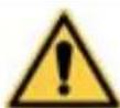
- Place the cable along the entire path, fixing it with the suitable pegs (B) spaced approximately 100 cm apart, and observing the installation requirements (See Par. 4.3 and Par. 4.4).
- Leave 2 m of cable or more to subsequently cut it to size in the final phase of connection.
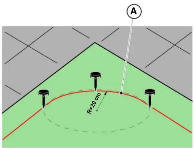
NOTE: In non-straight sections, make sure that the cable (A) does not get tangled. Position the cable in such a way as to form a regular curve with a radius of about 20 ~cm
NOTE: The perimeter cable used for installation must be at least 40 m. long. If the cable is shorter, it will be necessary to install the resistor for small perimeters. (See Par. 4.5.4. and Chap. 9 "Accessories").

WARNING:
Make sure that the cable is in contact with the ground along its path to prevent the robot lawn mower from damaging it.
text_image
A
R=20 cm
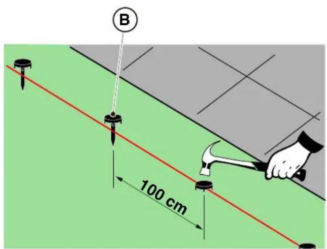
text_image
B
100 cm
POSITIONING UNDERGROUND
(CARRIED OUT ONLY BY AUTHORIZED RETAILER)
Turning to a STIGA retailer, the perimeter cable can also be installed using a specific wire-laying machine, without using pegs.
4.5.2. JUNCTION OF THE PERIMETER CABLE.
 | CAUTION:Danger of cutting hands. |  | CAUTION:Danger of dust in the eyes. |
Requirements and obligations:
- Joint for perimeter cable • Gloves
• Electrician's scissors • Glasses
- Pliers

GLOVES OBLIGATION: Use protective gloves to avoid cutting your hands.

GLASSES OBLIGATION: Use safety glasses to avoid the danger of dust in the eyes.
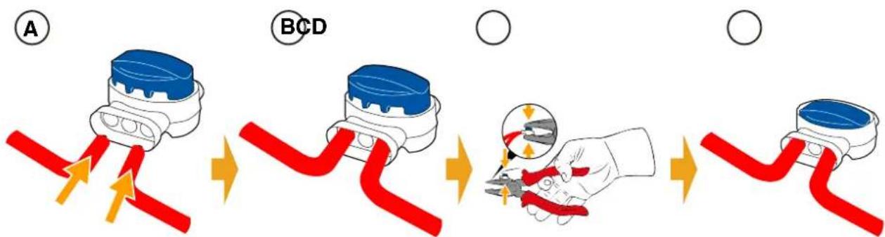
During the installation of the cable or in case of accidental breakage, it may be necessary to make junctions.
Procedure:
- Disconnect the docking station from the power supply.
- Place the perimeter cable as per position (A).
- Insert the ends of the cable into the joint as per position (B).
- Fully press the button on the upper side of the joint using a pair of pliers as per position (C).
- The perimeter cable is properly installed on the joint (D).

BAN:
Do not use insulating tape or joints of any other type that do not guarantee correct insulation (cable lugs, terminals, etc.). The soil moisture causes oxidation and the interruption of the perimeter cable.
text_image
A
BCD
O
4.5.3. INSTALLATION OF THE DOCKING STATION
 | CAUTION:Danger of cutting hands. |  | CAUTION:Danger of dust in the eyes. |
 | ELECTRICAL HAZARD:Connect the power supply only at the end of all the installation operations. If necessary during the installation, turn off the general power supply. | | |
Requirements and obligations:
- Flat land • Compact soil
- Docking station • Perimeter cable
• Power supply • Fixing pegs
- Screwdriver • Hammer
• Electrician's scissors • Gloves
- Glasses

GLOVES OBLIGATION:
Use protective gloves to avoid cutting your hands.

GLASSES OBLIGATION:
Use safety glasses to avoid the danger of dust in the eyes.
The docking station can be installed:
- aligned with the perimeter cable so that the robot can access it by navigating the perimeter cable clockwise.
Procedure:
- Check the installation requirements as indicated in par. 4.3.
- If necessary, prepare the ground so that the surface of the docking station (A) is at the same level as the lawn (B), the ground must be perfectly flat and compact in order to avoid deformation of the surface of the docking station.
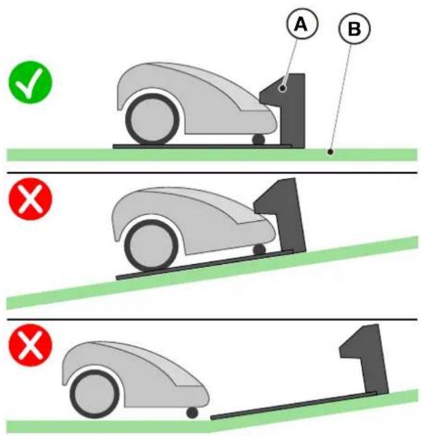
text_image
A
B
✓
×
1
×
1
-
Remove the cover (C).
-
Position the docking station:
- Aligned to the perimeter cable (D2) so that the robot is able to access it by navigating the perimeter cable in a clockwise direction.
- Insert the two ends of the cable into the appropriate slots (E2).
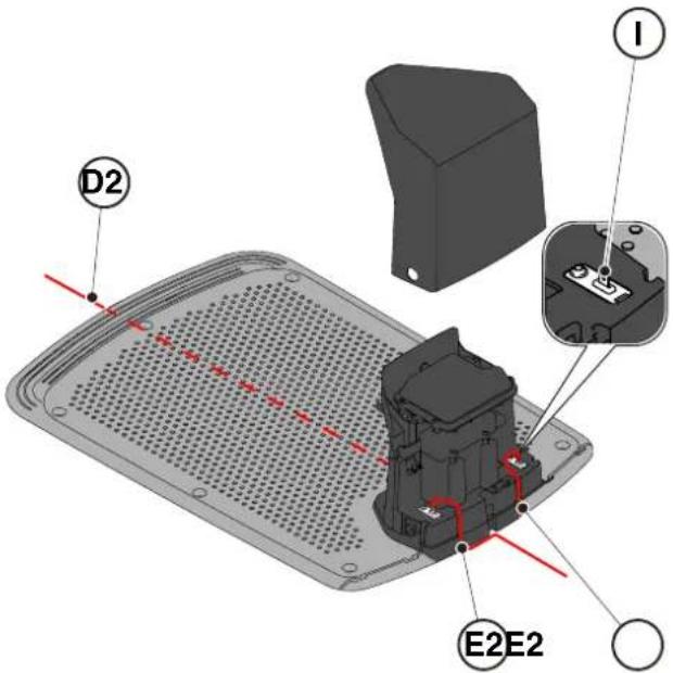
text_image
D2
I
E2E2
- Cut the ends of the cables to the exact length.
- Apply the self-drilling connectors on the cable (F), (G), (H).
- Connect the connectors to the terminals (I).
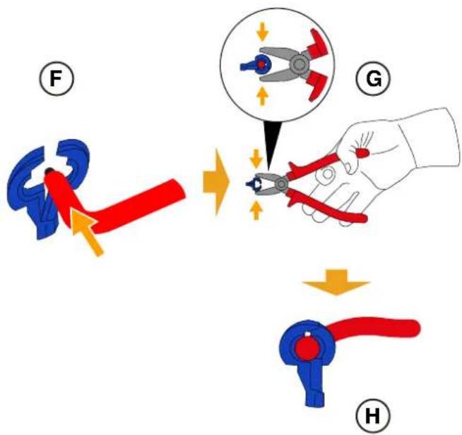
text_image
Diagram illustrating the process of hairpin tool application, showing steps from pinning to cutting and holding a hairpin.
STIGA
- Secure the docking station (L) to the ground with the fixing screws (M).
- Reposition the cover (C).
- Connect the power supply connector to the docking station and then insert the power supply plug into the electrical outlet.
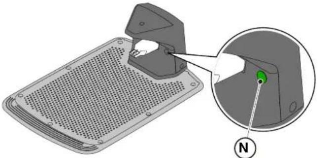
- When the robot lawn mower is not in the charging base, make sure that the indicator light on the charging base (N) is lit with a fixed light (see Par. 5.4)

WARNING:
The power cable, power supply unit, extension cord and all other electric cables which do not belong to the product must remain outside the cutting area to maintain their distance from hazardous moving parts and prevent damage to cables which may come into contact with live parts.
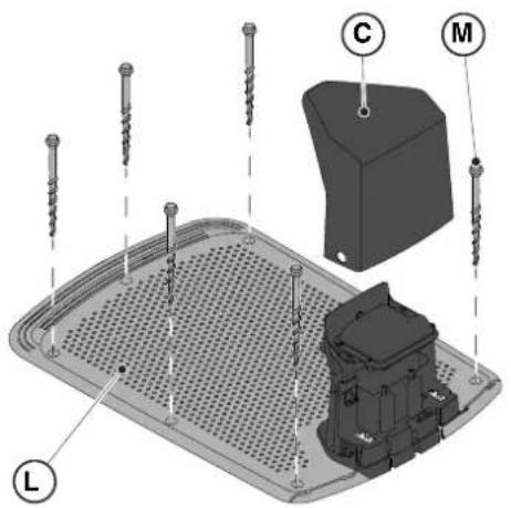
text_image
Technical diagram of a mechanical assembly with labeled parts L, C, and M, showing screw installation and component layout.

natural_image
3D diagram of a mechanical device with a green indicator light and a magnified view showing internal components (no text or symbols)
NOTE: If necessary, it is possible to extend the power cable to the docking station by using the extension cables. It is permitted to use a maximum of two 5-meter extension cables (See Chapt. 9 "Accessories").
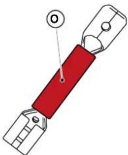
4.5.4. RESISTOR INSTALLATION FOR SMALL PERIMETERS
Requirements and obligations:
The perimeter cable used for the installation of the robot lawn mower must be at least 40 m. long. If the cable length is shorter, it is necessary to connect in series the resistor (See Ch. 9 “Accessories”) with the perimeter cable.
Procedure:
After having positioned and secured the docking station correctly (see par. 4.5.3), proceed as follows:
- Remove the cover (C).
- Cut the ends of the cables to the exact length.
- Apply the self-drilling connectors on the cable (F), (G), (H). (See par. 4.5.3).
- Connect the resistor (O) to the terminal (I) of the docking station.
- Connect the respective perimeter cable to the resistor (O).
- Connect the other perimeter cable directly to the other terminal of the docking station.
natural_image
Diagram of a red electrical fuse with a circular component labeled 'O' (no text or symbols beyond the label)

text_image
D2
C
O
I
E2E2
4.6. CHARGING THE ROBOT LAWN MOWER AFTER INSTALLATION
Requirements and obligations:
- Docking station.
Procedure:
- Recharge the robot lawn mower (See Par 5.5).
NOTE: When charged for the first time, the batteries must remain connected for at least 2 hours.
4.7. PRODUCT SETTINGS
Requirements and obligations:
The automatic operation of the robot lawn mower requires a series of settings that can be made via mobile device (smart phone) iOS or Android with the "STIGA GO" App installed.
The iOS app is downloadable from the iOS App Store. The Android app is downloadable from the Google Play Store.
The following functions can be set up from the app. Check the table of contents to see which functions are available for your model:
- Start, stop and force the robot lawn mower to return to the docking station.
- Select the work mode in a closed area that cannot be reached autonomously by the robot lawn mower.
- Select the Scheduled Job / Single Cutting Cycle mode.
- Schedule Working Hours for the days of the week.
- Set the Work Start Points to make cover the garden uniformly.
- Set the days of the week to perform the edge trimming.
- Enable a low energy eco mode.
- Enable and set the sensitivity of the Rain Sensor.
- Enable different users to use the robot lawn mower via app.
- Choose and contact your reference retailer.
NOTE: The images shown in this section are purely indicative and may differ over time from those of the product app.
| G 300 G 600 G | 1200 | |
| Border Cut |  |  |  |
| Go-To Cut Points | 1 3 5 | | |
| Eco Mode |  |  |  |
| Rain Sensor |  |  |  |
| Closed Area |  |  |  |
TABLE OF CONTENTS PRODUCT SETTINGS
4.7.1. PRELOGIN 31
4.7.2. SIGN UP 31
4.7.3. PAIRING 31
4.7.4. DEVICE PAGE 32
4.7.5. CLOSED AREA 32
4.7.6. SETTINGS 32
4.7.7. SPOT CUT / SCHEDULED 32
4.7.8. MOWING SESSIONS....32
4.7.9. GO-TO-CUT POINTS....33
When accessing the app for the first time users can:
- Access the information pages regarding STIGA retailers and products
- Complete the first time user sign-up;
- Complete the Log in for already registered users.
4.7.2. SIGN UP
The "Sign Up" section allows user registration and enables access to all functions of the app.
- The user can log in through their Google, Facebook and Apple accounts, or create a new account by filling in the required fields.
- The registration procedure requires an email verification.
4.7.3. PAIRING
The "Pairing" section allows you to associate your mobile device with the robot lawn mower via bluetooth connection.
- Press the "add" button to access the bluetooth pairing pages.
- Follow the set-up wizard to pair the product.
- Once the association is completed, the main page of the product will be displayed.
- Press the "device page" button to access the product page.
- Press the "options" button to access the menu where users can rename, disassociate and connect the robot lawn mower, or download the user manual.
NOTE: If the robot lawn mower is not detected by the mobile device, check whether the robot lawn mower is switched on and is in close proximity to the mobile device. Make sure that the lawn mower robot is not already paired with another user.
4.7.4. DEVICE PAGE
The "Device Page" section allows the user to check the robot lawn mower's status, to start it up for work or to force its return to the docking station.
- Press the "start" button to start the robot lawn mower.
- Press the "stop" button to stop the robot lawn mower.
- Press on the "return to base" button to force the robot lawn mower to return to base.
- Press on the "closed area" button to start the robot lawn mower working in an area that it cannot reach independently. (See Par. 4.7.5).
4.7.5. CLOSED AREA
NOTE: Check the availability of this function on the STIGA.GO App.
The "Closed Area" section allows to start the robot lawn mower in an enclosed area normally excluded from the work area because it is not reachable, but in any case delimited by the perimeter cable. (See Par. 4.4.3).
- Press the dedicated button to choose the "Closed Area" mode.
- Place the robot lawn mower inside the closed area and follow the guided procedure.
NOTE: The user can select whether to have the robot lawn mower work for the full duration of the battery life or for a shorter time set manually.
4.7.6. SETTINGS
The "Settings" section provides access to the robot lawn mower's settings screen.
- Press the "settings" button to enter Settings mode.
- Select the function to be set-up.
The “Spot Cut / Scheduled” selector allows the user to activate or deactivate the programmed work schedule.
The number of weekly hours to schedule are suggested by the app according to the size of the garden.
- If set to "Scheduled" the robot lawn mower works according to the scheduled work program.
- If set to "Spot Cut" the robot lawn mower works in a single work cycle.
4.7.8. MOWING SESSIONS
The "Mowing sessions" section allows you to program the time and working days of the robot lawn mower. The number of weekly hours to schedule are suggested by the app according to the size of the garden.
- Press on the "spot cut/scheduled" selector switch to enter the working hours set up menu and select a day of the week.
- Press the "add cutting time" button to add a new work schedule.
- Enter the work start and end times then confirm.
- The user has the option of applying the same working hours to several days of the week.
- The working time will be displayed on its scheduled weekday. By pressing on each working time it is possible to copy or delete it.
NOTE: The built-in clock of the robot lawn mower is automatically synchronised with the time on the mobile device whenever the robot is connected to the App via Bluetooth.
4.7.9. GO-TO CUT POINTS
NOTE: Check the availability of this function on the STIGA.GO App.
The “Go-To-Cut Points” section allows you to set one or more starting points for the robot lawn mower’s work in order to improve coverage in the different areas of the garden (see Par. 4.4). The number of settable start points depends on the model of the robot lawn mower.
The work start points are defined using the following parameters:
- Distance from the starting point to the docking station measured along the perimeter wire.
- Direction to reach the work point (clockwise or anticlockwise).
- The frequency at which the work point is reached expressed as a % of the total working time scheduled weekly.
4.7.10. BORDER CUT
The “Border cut” section allows to program the border cutting of the garden on a certain day.
- Choose the days in which to perform the border cut.
- Press the dedicated button to enable the function.
NOTE: The border cut can be activated only for the days of the week in which the robot lawn mower has been scheduled to work.
4.7.11. ECO MODE
NOTE: Check the availability of this function on the STIGA.GO App.
The 'Eco mode' function allows the user to set a low-energy mode by proportionally reducing the working time of the robot lawn mower compared to the time programmed by the user.
NOTE: It is advisable to use this function at times of the year when the grass grows more slowly.
4.7.12. RAIN SENSOR (DEPENDING ON THE MODEL)
The "Rain sensor" function allows you to enable or disable the rain sensor on the robot lawn mower.
- Press the dedicated button to enable the function.
- Select one of the three available rain sensor sensitivity levels.
4.7.13. APP LOCK
In order to prevent the robot lawn mower from being used by children or unauthorised persons, the keypad can be locked. This will allow the robot lawn mower to be controlled solely via the App.
Procedure:
- Activate or deactivate the Keypad/App Lock function from the app's 'settings' menu
NOTE: When the function is active, the keypad lock remains active even if the robot lawn mower is switched off.
4.7.14. USER MANAGEMENT
NOTE: Check the availability of this function on the STIGA.GO App.
The main user who performed the first registration of the product can invite other users to manage the robot lawn mower through the procedure accessible from the dedicated button.
NOTE: Added users can always be viewed and managed from the dedicated menu.
NOTE: The invited user must download the App on their mobile device and must register.
4.7.15. DEALER
The "Dealer" section allows to choose the reference service centre.
- By pressing on the "dealer" button, users can access the page where they will be able to select their dealer from a list.
4.7.16. MESSAGES
The "Messages" section displays messages\information.
- By pressing the "messages" button, users will access the page where they can view any messages/information from STIGA addressed to them.
4.7.17. PROFILE
The "Profile" section provides access to the user profile where the user can edit account details and change the password.
5. OPERATION
Requirements and obligations:
• Installation completed according to instructions (See Ch. 4)
- Programming the robot lawn mower according to the instructions (See Par. 4.7 for automatic function)
- Powered docking station
- Initial grass height in the range of operation of the robot lawn mower: 20-60 mm
- Battery charged (See Par. 5.5) • Cutting height suitably adjusted (See Par. 5.6).
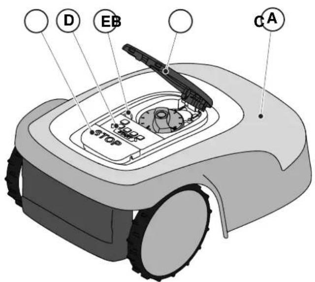
5.1. CHECK OF SAFETY DEVICES FOR STARTING THE ROBOT LAWN MOWER
Requirements and obligations:
- Safety key.
Procedure:
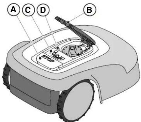
-
Check that the floating cover (A) is fitted correctly. If the cover is missing the robot lawn mower doesn't work.
-
Check that the safety key (E) is inserted If it is not inserted the robot lawn mower doesn't start.
-
Check that the stop button " STOP" (B) is not active. If pressed, it stops the robot lawn mower and opens the protective cover (C) of the control console (D).
-
Check that the robot lawn mower is positioned on the ground correctly. In case of excessive tilt ( ≥ 45%) or lift, the tilt sensors (inclinometer) stop the robot lawn mower.
text_image
D
EB
STOP
C A
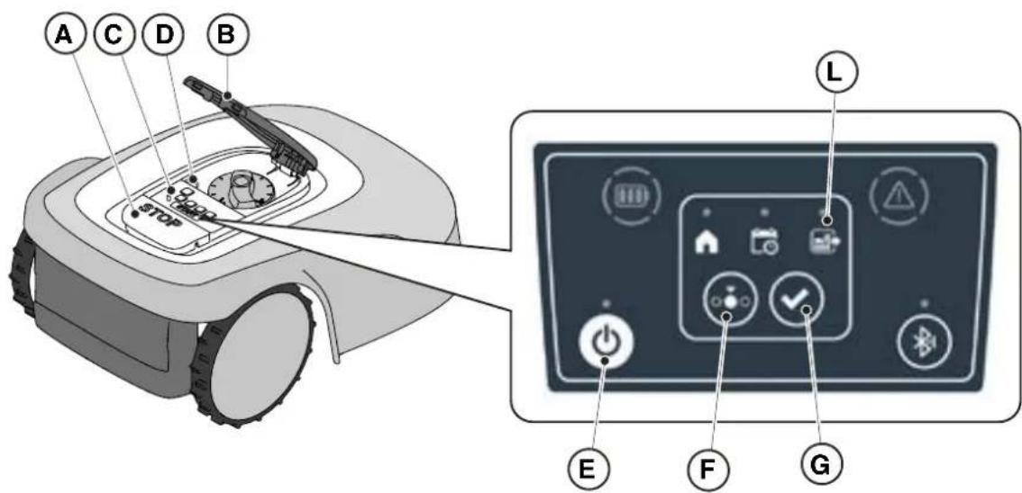
5.2. MANUAL FUNCTIONING OF THE ROBOT LAWN MOWER
The robot lawn mower can be used without performing the programming procedure described in Par. 4.7. In this mode the robot lawn mower carries out a work cycle, returns to the docking station and remains there until the next manual start.
Procedure:
- Place the robot mower on the docking station or within the perimeter of the installation.
- Press the "STOP" button (A) to open the cover (B) and access the control console (C).
- Press the "ON/OFF" button (E) for 5 seconds to switch on the robot lawn mower.
- Press the "SELECT MODE" button (F) until only the icon (L) flashes.
- Press the "CONFIRM" push button (G). The icon (L) lights up with a steady light to confirm the operation.
- Close the cover (B).
- The robot lawn mower will start operating.
text_image
A C D B
STOP
L
E F G
NOTE: this mode may not guarantee adequate coverage of the garden, both in terms of time required and in terms of uniformity of the cutting result, especially if the garden has an irregular shape. To achieve the maximum efficiency of the robot lawn mower, it is recommended to carry out programming (See par. 4.7).
NOTE: If after pressing the "CONFIRM" button (G), the "SELECT MODE" button (F) is pressed, the icons for the selected functions will start flashing again, requesting confirmation of the newly selected function. Press the "CONFIRM" button (G). The icons will once again light up with a steady glow.
NOTE: if the cover (B) is opened, either during work or with the robot in the base, the icons relating to the selected functions will flash, to indicate that it is necessary to confirm the operation before closing the cover again. If the cover is closed without pressing the The "CONFIRM" button (G), the robot will not perform any operation until a new command is given by the user.
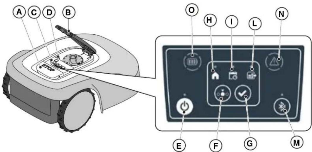
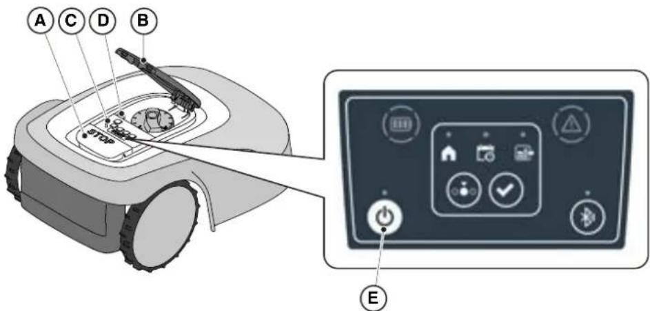
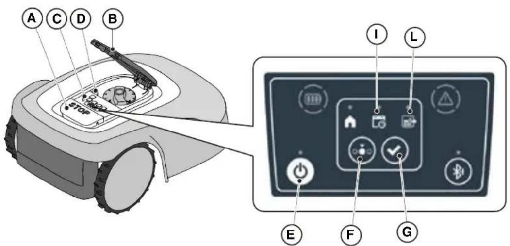
5.3. DESCRIPTION OF THE CONTROLS ON THE ROBOT LAWN MOWER
List of controls, indicators and their function:
- The "STOP" button (A): is used to safely stop the robot mower.
- The "SAFETY KEY" (D): is used for the safety shut-down of the robot lawn mower.
- The "ON/OFF" button (E): is used to turn the robot lawn mower on and off and resetting the alarms..
- The "MODE SELECTION" button (F): is used to select the operating mode of the robot lawn mower and to force it to return to the docking station.
- The "CONFIRM" button (G): is used to confirm the operating mode set.
- The "SCHEDULED PROGRAM" light icon (I): is used to display the scheduled program settings.
- The "SINGLE WORK CYCLE" light icon (.L): is used to display the single work cycle settings.
- The "RETURN TO BASE" light icon (H): is used to display the forced return-to-base setting of the robot lawn mower.
- The "BLUETOOTH" button (M): is used to display the bluetooth status.
- The "ALARM" light icon (N): is used to display the alarms status.
- The "BATTERY" light icon (O): is used to display the battery charging.
text_image
A C D B
O H I L N
E F G M
The "STOP" button (A) is a control that stops the robot lawn mower in safety conditions, whatever its operating condition is.
Procedure:
- Press the "STOP" button (A) while the robot lawn mower is moving or already still.
- When the "STOP" button (A) is pressed, the robot lawn mower stops and the cover (B) opens, allowing access to the other robot controls.
text_image
A
B
STOP
5.3.2. SAFE SHUTDOWN - SAFETY KEY
The safety key (D), by switching off, allows the robot lawn mower to be switched off safely.

OBLIGATION:
Always remove the safety key before any operation of cutting height adjustment, cleaning, transport and maintenance
Procedure:
-
Press the "STOP" button (A) to open the cover (B) and access the control panel (C).
-
Remove the safety key (D) and keep it in a safe place.
-
After carrying out the maintenance operations, insert the safety key to be able to switch on the robot lawn mower.
text_image
A C D B
STOP
The "ON / OFF" button (E) allows to switch the robot lawn mower on and off manually.
Procedure:
-
Press the "STOP" button (A) to open the cover (B) and access the control panel (C).
-
Press the "ON/OFF" button (E) for 5 seconds to switch on the robot lawn mower or to switch it off.
NOTE: To switch on the robot lawn mower, the safety key (D) must be inserted.
NOTE: Removing the safety key (D) shuts down the robot lawn mower, even if it was not previously switched off using the "ON / OFF" button.
NOTE: In case of active alarms, a double press of the "ON/OFF" button will reset the alarms.
text_image
A C D B
STOP
E
The "MODE SELECTION" button is used to activate or deactivate the set work program via the App and to select the forced return to the docking station. The robot lawn mower operates according to the possible selections described below.
KEYBOARD SELECTIONS AND ROBOT OPERATION
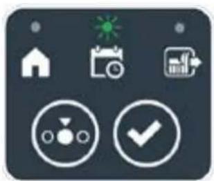
SCHEDULED PROGRAM
The robot lawn mower operates according to the programming set via the app.
RETURN TO BASE + SCHEDULED PROGRAM
The robot lawn mower returns to the docking station. The robot lawn mower will resume working from the following set start time.
SINGLE WORK CYCLE + SCHEDULED PROGRAM
The robot lawn mower performs a single forced work cycle and returns to the docking station when finished. The robot lawn mower will resume working from the following set start time.
SINGLE WORK CYCLE
The robot lawn mower performs a single forced work cycle and returns to the docking station.
The robot lawn mower stays in the base until the user intervenes manually.
RETURN TO BASE + SINGLE WORK CYCLE
The robot lawn mower returns to the docking station. The robot lawn mower stays in the base until the user intervenes manually.
natural_image
Icon set with home, calendar, and checkmark symbols (no text or numbers)

natural_image
Icon set with home, calendar, and checkmark symbols (no text or numbers)

natural_image
Icon set with home, calendar, and checkmark symbols (no text or numbers)

natural_image
Icon set with home, calendar, and checkmark symbols on dark background (no text or numbers)

natural_image
Icon set with home, camera, and checklist symbols (no text or numbers)
STIGA
Procedure:
- Press the "STOP" button (A) to open the cover (B) and access the control console (C).
- Press the "MODE SELECT" button (F) until the icons of the functions you wish to activate flash. The icons relating to the selected functions flash.
- Press the "CONFIRM" push button (G). The icons of the selected functions light up steadily to confirm the action.
- Close the cover (B).
- The robot lawn mower will start working according to the set mode.
NOTE: If after pressing the "CONFIRM" button (G), the "SELECT MODE" button (F) is pressed, the icons for the selected functions will start flashing again, requesting to confirm the newly selected function. Press the "CONFIRM" button (G). The icons return to a steady light.
NOTE: if the cover (B) is opened, either during work or with the robot in the base, the icons relating to the selected functions will flash, to indicate that it is necessary to confirm the operation before closing the cover again. If the cover is closed without pressing the "CONFIRM" button (G), the robot will not perform any task until a new command is given by the user.
NOTE: If the robot battery is low, the battery icon flashes red to indicate that the selected action cannot be performed.
NOTE: NOTE: the robot lawn mower starts only after closing the cover (B).
NOTE: The robot lawn mower goes to the docking station with the cutting device switched off.
text_image
A C D B
STOP
I L
E F G
NOTE: The robot lawn mower can be used in “SINGLE WORK CYCLE” mode even without programming the working hours via the App. This mode may not guarantee adequate coverage of the garden, both in terms of time required and in terms of uniformity of the cutting result, especially if the garden has an irregular shape. To achieve the maximum efficiency of the robot lawn mower, it is recommended to carry out programming (See par. 4.7).
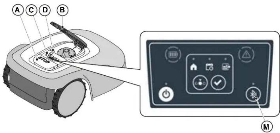
The robot lawn mower handles automatically the Bluetooth connection with external mobile devices. The Bluetooth connection is available at all times when the robot lawn mower is switched on. It is possible to connect only one mobile device at a time to the robot lawn mower via Bluetooth. The robot lawn mower automatically disconnects from the device when the app is closed. The 'BLUETOOTH' button (M) is used only by the service centre for diagnostic purposes.
NOTE: For pairing the device with the robot lawn mower via Bluetooth, see (Par. 4.7.3 Pairing).
text_image
A C D B
STOP
M
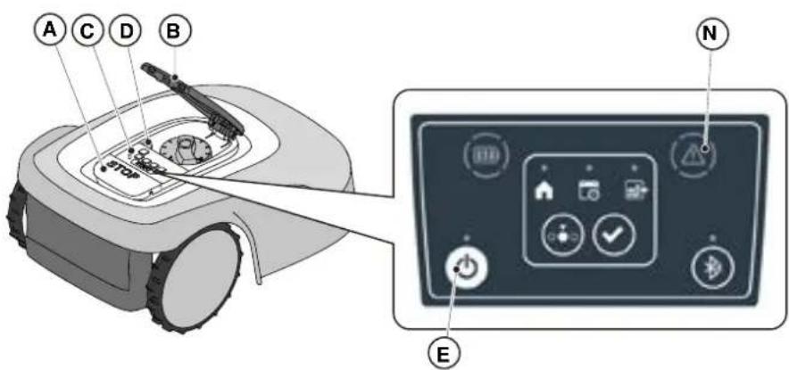
5.3.6. DISPLAY OF ALARM STATES-ALARM ICON
The "ALARM" light icon (N) indicates an operating anomaly.
Procedure:
- Press the "STOP" button (A) to open the cover (B) and access the control panel (C).
- Check the alarm status through the red light icon (N):
- After resolving the fault, press the "ON/OFF" button (E) twice in rapid succession to reset the alarm. The light icon (N) goes out, and the robot lawn mower can be restarted. If the icon (N) does not go off, remove the safety key (D), wait a few seconds and then switch the robot lawn mower on again using the "ON/OFF" button (E). If the problem persists, contact a service centre.
NOTE: Details about anomalies are viewable on the App.
text_image
A C D B
STOP
N
E
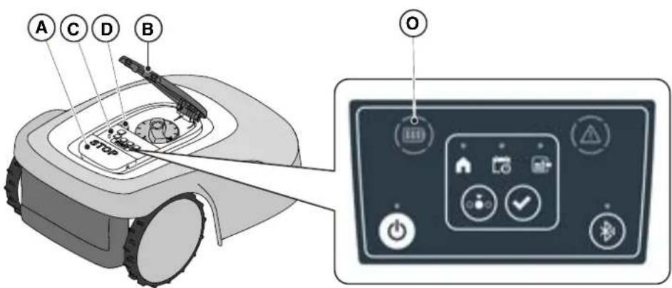
5.3.7. BATTERY CHARGE DISPLAY-BATTERY ICON
The "BATTERY" light icon (O) indicates the battery charge status.
Procedure:
- Press the "STOP" button (A) to open the cover (B) and access the control panel (C).
-
Check the battery charging status through the light icon (O):
-
Blue icon: the battery is charged (charge level >40 %).
- Red icon: the battery is charging (charge level 15-40 %).
-
Flashing red icon: the battery charge is low (charge level <15%).
-
If the robot lawn mower is charging, the light icon (O) flashes.
NOTE: if the battery icon (O) flashes rapidly red when a command is pressed, the operation cannot be carried out and it will be necessary to charge the battery manually (See chapter 5.5).
text_image
A C D B
O
5.3.8. STARTING THE ROBOT LAWN MOWER
To start up the robot lawn mower, follow the procedure described in Par. 5.3.4 "SCHEDULED PROGRAM SELECTION / SINGLE WORK CYCLE / FORCED RETURN TO DOCKING STATION - MODE SELECTION BUTTON".
5.4. FUNCTIONING OF THE DOCKING STATION
The docking station is equipped with an indicator light (N) that lights up in the following manner:
- Warning light off: the docking station is powered off or the robot is on the base.
- Steady indicator light: the perimeter cable is correctly connected to the charging base, and the perimeter signal is correctly transmitted;
- Indicator light flashing slowly: the perimeter cable is not connected or is interrupted (the perimeter cable integrity check is not performed continuously, but only when the robot leaves the charging base or the base is powered);
- Warning light flashing quickly: the perimeter cable is too short (see Par. 4.5.4) or there is a fault in the docking station.
- Indicator light flashing rapidly twice or three times: the docking station has detected a short circuit on the charging contacts. (See Chapter 7).
natural_image
3D diagram of a device with a labeled component (N) and an inset showing a green button, no text or symbols present.
5.5. BATTERY CHARGING
The "BATTERY CHARGING" procedure allows to recharge the robot lawn mower manually.
Requirements and obligations:
- Docking station connected to the mains.
Procedure:
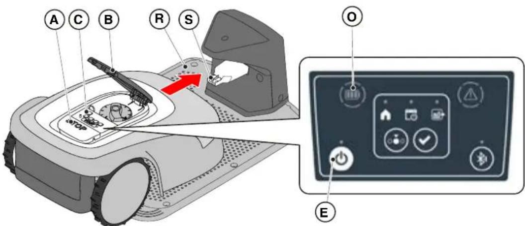
- Position the robot lawn mower on the docking station (R).
- Slide the robot lawn mower onto the docking station, until the charging connector (S) is engaged.
- Press the "STOP" button (A) to open the cover (B) and access the control panel (C).
- Turn the robot lawn mower on with the "ON/OFF" button (E).
- When the "BATTERY" icon (O) flashes blue, the robot lawn mower is charging.
- Close the cover (B).
- Leave the robot lawn mower to charge for at least the time shown in Par. 4.6.
NOTE: Charging the battery before winter storage should be carried out as shown in Par. 6.4.
text_image
A C B R S
O
E
5.6. CUTTING HEIGHT ADJUSTMENT
The "CUTTING HEIGHT ADJUSTMENT" procedure describes how to adjust the height of the cutting blades.
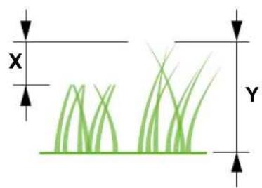
- The length X of grass cut by the robot lawn mower must not exceed 10mm.
- The robot lawn mower's operating range is 20-60 mm (cutting height).
- The initial height of the grass Y must therefore be 70mm maximum.
At the first installation or at the beginning of the mowing season, if necessary, prepare the garden with a traditional lawn mower to bring the initial height of the grass to an appropriate value.
NOTE: If you want to cut the grass more than 10mm, adjust the cutting height so that the cut grass part is 10mm. Lower the cutting height further only after the garden has been mowed evenly.
natural_image
Diagram of green grasses with X and Y axis labels (no text or symbols on the grass itself)
Procedure:
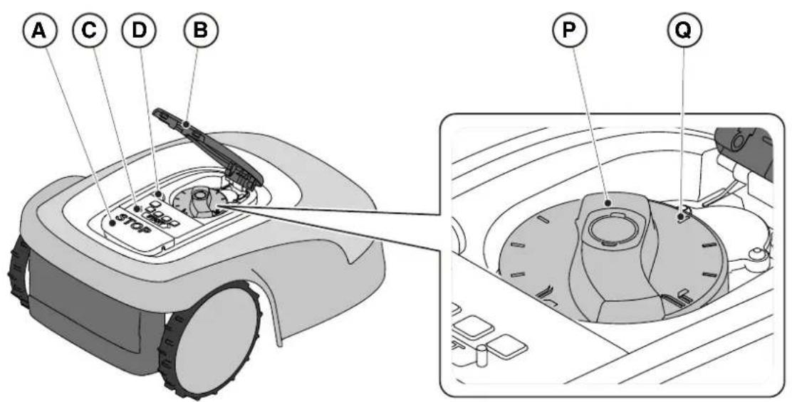
- Press the "STOP" button (A) to open the cover (B) and access the control panel (C).
- Remove the safety key (D).
- Use the height adjuster (P) to select the desired cutting height so that the cut grass part is no more than 1 cm.
- Insert the safety key (D).
NOTE: On the knob there is a scale graduated from 1 to 10 (Q) to be used as a reference.
text_image
A C D B
STOP
P Q
6. MAINTENANCE
6.1. SCHEDULED MAINTENANCE
 | CAUTION:Only use original spare parts. |  | CAUTION:Do not modify, tamper with, elude or eliminate the safety devices installed. |
For a better operation and longer life, be sure to clean the product regularly and replace worn parts.
Perform the interventions following the frequency indicated in the table.
| FREQUENCY COMPONENT TYPE OF INTERVENTION REFERENCE | | |
| Weekly Blade Clean and check blade | efficiency | (See Par. 6.2) | |
| If the blade is bent due to impact or if it's worn, replace it. | (See Par. 6.3) | |
| Recharging contacts | Clean and eliminate any oxidising. | (See Par. 6.2) |
| Monthly Robot lawn mower | Carry out cleaning. (See Par. 6.2) | | |
| Docking station and power cables | Check for wear or deterioration and replace if necessary. | (Contact an authorised service centre) | |
| At the end of the mowing season or every six months if the robot lawn mower is not used | Battery Perform the | pre-storage charging of the battery. | (See Par. 6.4) | |
| Annual or at the end of the cutting season | Robot lawn mower | Carry out the servicing at an authorized service centre. | (See Par. 6.1) | |
It is necessary to carry out a maintenance servicing annually at an authorized service centre to keep the robot lawn mower in good working conditions.
The servicing provides for a series of verifications including:
- The internal and external cleaning of the robot lawn mower;
- the general check of the status of the robot lawn mower;
• the replacement of worn parts;
• the checking of the battery status;
• the verification of tightening torques;
- the verification and possible replacement of the impact and lifting kinematic mechanisms and their protective bellows;
- the check and, if necessary, replacement of the rubber bellows protecting the blade motor, to maintain the protection specifications against water infiltrations
- the replacement of the sealing gaskets of the bodies and the battery compartment to maintain the specifications of protection against water infiltrations.
NOTE: any malfunction due to not having carried out the annual servicing will not be recognized under warranty.
6.2. PRODUCT CLEANING
CAUTION: Danger of cutting hands.

CAUTION: Danger of dust in the eyes.
Requirements and obligations:
- Sponge • Dry cloth
- Neutral soap • Gloves
- Brush • Glasses
- Water

GLOVES OBLIGATION: Use protective gloves to avoid cutting your hands.

GLASSES OBLIGATION: Use safety glasses to avoid the danger of dust in the eyes.
Procedure:
- Press the "STOP" (A) button to stop the robot lawn mower and open the protective cover (B).
- Remove the safety key (C).
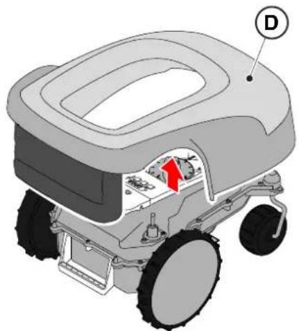
- Remove the floating cover (D) to make the cleaning easier.
- Clean all the external surfaces of the robot lawn mower with a sponge dampened in lukewarm water and neutral soap.
text_image
A
C
B
STOP
natural_image
Diagram of a robotic vehicle with labeled parts (D) and internal components, no readable text or symbols beyond labels

WARNING:
Too much water can filter in and damage electrical parts.

WARNING:
Do not modify, tamper with, elude or eliminate the safety devices installed.

BAN:
Do not use pressurized water jets.

BAN:
To avoid irreversible damage to the electrical and electronic components, do not immerse the robot lawn mower, partially or completely, in water.

BAN:
Do not wash the internal parts of the robot lawn mower to avoid damaging the electrical and electronic components.

BAN:
Do not use solvents or petrol so as not to damage varnished surfaces and plastic parts.
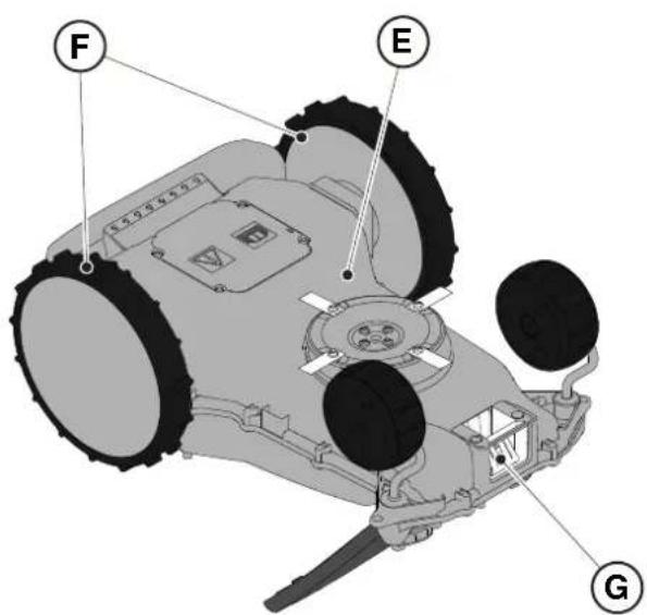
- Remove mud and dirt from the drive wheels (F).
- Clean the underside (E) of the robot lawn mower (cutting blade area, front and rear wheels). Use a suitable brush to remove encrustations and / or debris that could prevent the robot lawn mower from working properly. Complete the cleaning with a damp sponge.
- Put the floating cover (D) back on, making sure that it is correctly fastened to the supports.
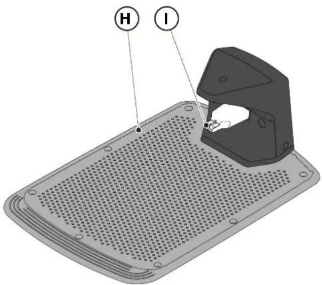
- Clean the battery charging connector (G).
- Clean the docking station (H) and the contact connector (I) from accumulated residues.
text_image
Labeled diagram of a tracked vehicle showing components F, E, and G with visible parts and motion indicators.
text_image
H
I
6.3. REPLACEMENT OF THE CUTTING BLADES

CAUTION: Danger of cutting hands.
Requirements and obligations:
- Safety key • Key
• Cutting blades • Gloves

GLOVES OBLIGATION:
Use protective gloves to avoid cutting your hands.
Procedure:
- Press the "STOP" (A) button to stop the robot lawn mower and open the protective cover (B).
- Remove the safety key (C).
text_image
A
C
B
STOP
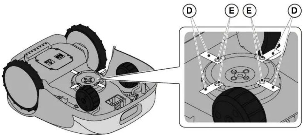
- Turn the robot lawn mower upside down, taking care not to damage the floating cover.
- Unscrew the fixing screws (E).
- Replace the cutting blades (D).
- Unscrew the fixing screws (E).
text_image
Technical diagram of a robotic vehicle showing internal components and labeled parts (D, E, D)
6.4. WINTER BATTERY MAINTENANCE AND STORAGE
Procedure:
- Charge the battery according to the guided procedure in the App, accessible from the "Settings" page.
- Clean the robot lawn mower (See Par. 6.2).
- Check the robot lawn mower is switched off and store in a dry place, protected from icy conditions.
- The battery must be recharged every 6 months and, in any case, before winter storage.
NOTE: The guided procedure registers the successful recharging of the battery in the cloud, and is to be considered completed if the date of the winter pre-storage recharge is updated.
NOTE: Registering the charge through the app procedure is required for the battery warranty to be valid.
NOTE: The battery must be recharged every 6 months and, in any case, before winter storage.
natural_image
3D rendering of a gray robotic device with a black handle and circular base (no text or symbols visible)
6.5. BATTERY REPLACEMENT
Battery replacement is the sole responsibility of the STIGA TECHNICAL ASSISTANCE STAFF. If the battery needs to be replaced, contact a service centre or your retailer.
7. TROUBLESHOOTING

CAUTION:
Stop the robot lawn mower and bring it back to safety conditions (See Par. 5.3.2).
Below there is the list of any anomalies that may arise during the work phase.
| PROBLEM CAUSES SOLUTIONS | |
| Abnormal vibrations.The robot lawn mower is noisy. | Damaged cutting disc or blades Replace the damaged components (See Par. 6.3). |
| Cutting device blocked by residues (tapes, ropes, plastic fragments, etc.). | Switch off the robot lawn mower in safety conditions (See Par. 2.3). Unlock the cutting blade. |
| The robot lawn mower was started in the presence of unexpected obstacles (fallen branches, forgotten objects, etc.). | Switch off the robot lawn mower in safety conditions (See Par. 2.3). Remove obstacles and restart the robot lawn mower (See Par. 5.3.9). |
| Electric motor failure Replace the motor, contact the nearest authorized service centre. |
| Grass too tall Increase the cutting height (See Par. 5.6). |
|
|
| The robot lawn mower does not position itself properly inside the charging station. | Incorrect position of the perimeter cable. | Check the connection of the charging station (See Par. 4.5.3). |
| Land subsidence in the vicinity of the docking station. | Restore the correct positioning of the docking station. (See Par. 4.5.3). |
| The mower robot behaves abnormally around perimeter obstacles. | Perimeter cable laid in the wrong way | Reposition the perimeter cable correctly (clockwise) (See Par. 4.5.1). |
| The robot lawn mower works at the wrong times. | Working time set incorrectly Reset the working hours (See Par. 4.7.8). |
| The working area is not mowed completely. | Insufficient working hours. Extend working hours (See Par. 4.7.8). |
| Cutting device with encrustations and / or residues. | Switch off the robot lawn mower in safety conditions (See Par. 2.3). Clean the cutting device. |
| Pivoting cutting blades blocked by encrustations or residues. | Switch off the robot lawn mower in safety conditions (See Par. 2.3). Replace the cutting blades. |
| The working area is too large for the robot lawn mower's capacity. | Reduce the work area (see Technical Data Par. 1.2). |
| Batteries about to exhaust their life cycle. | Replace the batteries with original spare parts (See Par. 6.5). |
| Batteries are not charged completely. | Clean and eliminate any oxidation from the contact points (See Par. 6.2). Recharge the batteries. |
| Parts of the garden not completely mowed. | Wrong cut point programming. Correctly program the secondary cut points correctly (See Par.. 4.7.9). |
| The docking station light does not turn on when the robot is out of the docking station. | The supply voltage is missing or there is a fault in the docking station. | Check that the power supply unit is plugged in correctly. Check the integrity of the power supply connection cable. |
| The docking station indicator lights up flashing slowly. | The perimeter cable is not connected or is broken | Check the installation and repair the break (See Par. 4.5.2) |
| The docking station indicator light flashes rapidly. | The perimeter cable is too short or there is a fault in the charging base. | Check that the length of the perimeter cable is greater than indicated in Par. 4.5.1. If necessary, install the resistor (See Par. 4.5.4). If the problem persists, contact a service centre. |
| The docking station indicator lights up flashing twice or three times rapidly. | The docking station has detected a short circuit on the charging contacts. | Disconnect the docking station from the mains, rectify any short circuits and clean the charging contacts of the docking station and the robot. Reconnect the docking station to the mains. If the problem persists, contact a service centre. |
| The Warning icon lights up on the keypad. | It indicates anomaly / failure conditions. | See the app for more information or contact a service centre. |
7.1. MAIN MESSAGES FROM APP
| PROBLEM CAUSES SOLUTIONS | |
| “No Signal” appears on the App while the robot lawn mower is inside the perimeter and the LED transmitter in the docking station is on. | The robot lawn mower has a problem in receiving the signal. | Contact an authorized service centre. |
| “Out of perimeter ” appears on the app. | Ground slopes too much Delimit the area with excessive slope (See Par. 4.3). |
| Perimeter cable laid in the wrong way | Check that the cable is installed correctly (excessive depth, proximity to metal objects, distance between the cable that delimits two elements, etc.). (See Par. 4.5.1). |
| Perimeter cable for delimiting internal areas (flower beds, bushes, etc.) incorrectly laid. | Reposition the perimeter cable correctly (go around the obstacle in the same direction of travel of the perimeter.) (See Par. 4.5.1). |
| Overheated power supply unit. Adopt suitable solutions to reduce power supply unit temperature (air or modify installation area, etc.) (See Par. 4.3). |
| "Lifted Robot" appears on the App | The robot lawn mower is lifted from the ground. | Check that the robot lawn mower is not blocked or obstructed by any objects. Clean and remove any grass residues under the hood that may obstruct the sensors (See Par. 6.2). |
| "Wheel error" appears on the app. | Uneven ground or with obstacles stopping the movement. | Check that the lawn to be mowed is uniform with no holes, stones or other obstacles. Otherwise, proceed with any necessary site clearance work ( See Par. 4.3). |
| One or both motors working the wheel drive have failed | Replace the motor, contact the nearest authorized service centre. |
| The app displays “Tall Grass” or “Mowing Error”. | Blocked or damaged cutting disc. | Stop the robot lawn mower in safety conditions (See Par. 2.3) Release the cutting disc from objects that cause it to block or replace the cutting disc with a new one (See ). 6.3). |
| Pivoting cutting blades worn or blocked by encrustations or residues. | Stop the robot lawn mower in safety conditions (See Par. 2.3). Release and clean or replace the cutting blades (See Par. 6.3). |
| The robot lawn mower was started in the presence of unexpected obstacles (fallen branches, forgotten objects, etc.). | Stop the robot lawn mower in safety conditions (See Par. 2.3). Remove the obstacles and restart the robot lawn mower. |
| Electric motor failure Replace the motor, contact the nearest authorized service centre. |
| Grass too tall Increase the cutting height (See Par. 5.6). Make a perimeter cut. |
| The App displays "Tipping". | The robot lawn mower is on a slope that is higher than the allowed limits. | Exclude the area with the slope beyond the allowed limits by delimiting it (See Par. 4.3) |
8. TRANSPORT, STORAGE AND DISPOSAL
8.1. TRANSPORT
Procedure:
NOTE: We recommend using the original packaging for transport over long distances.
- Press the "STOP" (A) button to stop the robot lawn mower and open the protective cover (B).
- Remove the safety key (C).
- Clean robot lawn mower as shown in Par. 6.2 "PRODUCT CLEANING".
- Lift the robot lawn mower by the handle (D) and carry it, taking care to keep the cutting blade away from the body.
- Reposition the robot lawn mower in its original packaging.
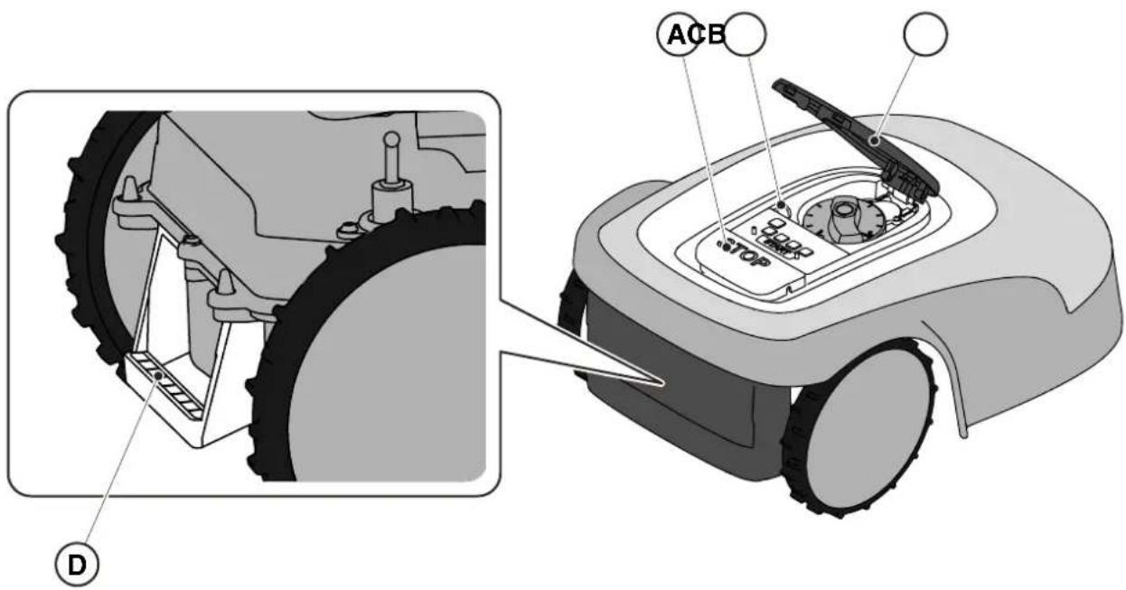
text_image
ACB
TOP
D
8.2. STORAGE
The robot lawn mower must be stored horizontally in a dry and frost-free place after cleaning and charging the battery in the winter (see Chapter 6). During long periods of inactivity, disconnect the docking station from the mains.
8.3. DISPOSAL

WARNING:
To remove the battery from the robot lawn mower, contact an authorized service centre.
Procedure:
- Dispose of the product packaging in a sustainable way in the appropriate collection containers or at special centres authorized for collection.
- Dispose of the robot lawn mower in accordance with local legal requirements.
- Contact appropriate facilities for recycling and disposal as the robot lawn mower is classified as WEEE (Waste Electrical and Electronic Equipment).
- Dispose of old or used batteries in a sustainable way in collection containers or at authorized collection centres.
9. ACCESSORIES
| Art. number Description Specifications | |
| 1127-0009-01 Cutting blades 12 pcs | |
| 1127-0011-01 Docking station cover For additional protection against rain and sunlight |
| 1127-0010-01 Cable extension for charger Cable to extend the connection between the power supply and the docking station - L=5 m |
| 1127-0020-01 Cable extension for charger Cable to extend the connection between the power supply and the docking station - L=15 m |
| 1127-0012-01 Installation KIT Small Perimeter cable ∅ 2,7 mm - L=150 m + 200 fixing pegs + 5 cable connectors + 5 docking station cable connectors |
| 1127-0013-01 Installation KIT Medium Perimeter cable ∅ 2,7 mm - L=300 m + 400 fixing pegs + 5 cable connectors + 5 docking station cable connectors |
| 1127-0000-01 Cable reel 150 m Perimeter cable ∅ 2,7 mm - L=150 m |
| 1127-0001-01 Cable reel 300 m Perimeter cable ∅ 2,7 mm - L=300 m |
| 1127-0002-01 Cable reel 500 m Perimeter cable ∅ 3,4 mm - L=500 m |
| 1127-0006-01 Fixing pegs (100 pcs) Pegs to fix the perimeter cable - 100 pcs |
| 1127-0008-01 Docking station fixing pegs 8 pcs | |
| 1127-0004-01 Cable connectors Joints for the repairing of the perimeter wire- 5 pcs |
| 1127-0005-01 Docking station cable connectors | Connectors to connect the perimeter wire to the docking station - 5 pcs |
| 122063053/0 | Small garden resistor | Resistor for installations with less than 40 m of perimeter cable |
10. WARRANTY
The warranty conditions are intended for consumers only, i.e. non-professional operators.
The warranty covers all material quality and manufacturing defects recognised during the warranty period by your Dealer or Authorised Service Centre.
The warranty is restricted to the repair or replacement of components recognised as faulty.
It is advisable to send your machine once a year to an authorized service workshop for servicing, assistance and safety device inspection.
The warranty only applies to machines subjected to regular maintenance.
The warranty does not cover damages resulting from:
- Failure to become familiar with the documentation accompanying the machine (Instruction manuals).
• Professional use.
- Carelessness, negligence.
- External causes (lightning, impact, presence of foreign bodies inside the machine) or incidents.
- Incorrect use or assembly prohibited by the manufacturer
- Poor maintenance.
- Modification to the machine.
- Use of non-genuine spare parts (adaptable parts).
- Use of accessories not supplied or approved by the manufacturer (e.g. cutting devices).
The warranty does not cover:
- Maintenance operations (described in the instruction manual).
- Normal wear of consumables such as cutting devices and wheels.
• Normal wear and tear.
- Deterioration in the appearance of the machine due to use.
• Cutting means supports.
- Damage resulting from an installation that does not comply with the user manual.
- Any corrosion or damage to the perimeter cable
- Damage caused by water infiltration due to the use of a high pressure washing device or by immersion in water, for example when puddles of water form from heavy rain.
- Damage caused by improper storage or improper use of the battery.
- Damage caused by using non-original batteries.
- Any additional cost possibly connected to the repair under warranty, such as moving the machine to the user's premises, bringing the machine to the Dealer, hiring equipment or contracting other companies for any garden maintenance work while the machine is out of service.
The user is protected by his or her own national legislation. The user's rights under the national laws or his or her own country are not in any way restricted by this warranty.
(Supply of Machinery (Safety) Regulations 2008, S.I. 2008 No. 1597, Annex II, part A)
- The company: ST. S.p.A. – Via del Lavoro, 6 – 31033 Castelfranco Veneto (TV) – Italy
- Hereby declares under its own responsibility that the machine:
Robotic lawnmower
a) Homologation type: SRSW01
c) Serial number: 22A••RMO000001 ÷ 99L••RMO999999
d) Engine: battery-operated
- Conforms to UK Regulations:
• S.I. 2008/1597 - Supply of Machinery (Safety) Regulations 2008
• S.I. 2016/1091 - Electromagnetic Compatibility Regulations 2016
- S.I. 2012/3032 - The Restriction of the Use of Certain Hazardous Substances in Electrical and Electronic Equipment Regulations 2012
• S.I. 2017/1206 - Radio Equipment Regulations 2017
- Reference to harmonised standards:
EN 60335-1:2012 / AC:2014 / A11:2014 / A13:2017 / EN 61000-3-2:2019
A1:2019 / A2:2019 / A14:2019 EN 61000-3-3:2013 / A1:2019
EN IEC 63000:2018 EN 300 328 V2.2.2
EN 303 447 V1.2.0
EN 50636-107:2015 / A1 / A2
EN 301 489-17 V3.2.4
EN 62479:2010
EN 55014-1:2017 / A11:2020
EN 55014-2:2015
i) Cutting width: 18 cm
n) Person authorised to compile the technical file: ST. S.p.A.
Via del Lavoro, 6
31033 Castelfranco Veneto (TV) - Italia
o) Castelfranco Veneto, 01/12/2022 CEO Stiga Group
ST. S.p.A.
Via del Lavoro, 6
31033 Castelfranco Veneto (TV) - Italia
Sean Robinson

UK Importer:
STIGA LTD
Unit 8, Bluewater Estate Plympton,
Devon, PL7 4JH, England

| FR (Traduction de la notice originale)Déclaration CE de Conformité (Directive Machines 2006/42/CE, Annexe II, partie A)1. La Société2. Déclare sous sa propre responsabilité que la machine : Robot-tondeusea) Type / Modèle de Basec) Série d) Moteur: batterie3. Est conforme aux prescriptions des directives :4. Renvoi aux Normes harmoniséesi) Largeur de coupen) Personne habilitée à établir le Dossier Technique :o) Lieu et Date | DE (Übersetzung der Originalbetriebsanleitung)EG-Konformitätserklärung (Maschinenrichtlinie 2006/42/EG, Anhang II, Teil A)1. Die Gesellschaft2. Erklärt auf eigene Verantwortung, dass die Maschine: Mährobotera) Typ / Basismodellc) Seriennummerd) Motor: Batterie3. Den Anforderungen der folgenden Richtlinien entspricht:4. Bezugnahme auf die harmonisierten Normeni) Schnittbreiten) Zur Verfassung der technischen Unterlagen befugte Person:o) Ort und Datum | NL (Vertaling van de oorspronkelijke gebruiksaanwijzing)EG-verklaring van overeenstemming (Richtlijn Machines 2006/42/CE, Bijlage II, deel A)1. Het bedrijf2. Verklaart onder zijn eigen verantwoordelijkheid dat de machine: Robotmaaiera) Type / Basismodelc) Serienummerd) Motor: accu3. Voldoet aan de specificaties van der richtlijnen:4. Verwijzing naar de Geharmoniseerde normeni) Snijbreedten) Bevoegd persoon voor het opstellen van het Technisch Dossiero) Plaats en Datum |
| ES (Traducción del Manual Original)Declaración de Conformidad CE (Directiva Máquinas 2006/42/CE, Anexo II, parte A)1. La Empresa2. Declara bajo su propia responsabilidad que la máquina: Robot cortacéspeda) Tipo / Modelo Basec) Matrículad) Motor: bateria3. Cumple con las especificaciones de las directivas:4. Referencia a las Normas armonizadasi) Amplitud de corten) Persona autorizada a realizar el Manual Técnico:o) Lugar y Fecha | PT (Tradução do manual original)Declaração CE de Conformidade (Diretiva de Máquinas 2006/42/CE, Anexo II, parte A)1. A Empresa2. Declara sob a própria responsabilidade que a máquina: Robot corta-relvaa) Tipo / Modelo Basec) Matrículad) Moto: Bateria3. É conforme às especificações das diretivas:4. Referência às Normas harmonizadasi) Amplitude de corten) Pessoa autorizada a elaborar o Caderno Técnicoo) Local e Data | NO (Oversettelse av original bruksanvisning)EF- Samvarserklæring (Maskindirektiv 2006/42/EF, Vedlegg II, del A)1. Firmaet2. Erklærer på eget ansvar at maskinen: Robotgressklippera) Type / Modellc) Serienummerd) Motor: batteri3. Oppfyller kravene i direktivene:4. Henvisning til harmoniserte standarderI) Klippebredden) Person som har fullmakt til å ufterdige teknisk dokumentasjon:o) Sted og dato |
| SV (Översättning av bruksanvisning i original)EG-försäkran om överensstämmelse (Maskindirektiv 2006/42//EG, bilaga II, dela)1. Företaget2. Försäkrar på eget ansvar att maskinen: Gräsklipparrobota) Typ / Basmodellc) Serienummerd) Motor: batteri3. Överensstämmer med föreskrifterna i direktivet4. Referens till harmoniserade standarderi) Skärbreddn) Auktoriserad person för upprättandet av den tekniska dokumentationen:o) Ort och datum | DA (Översættelse af den originale brugsanvisning)EF-overensstemmelseserklæring (Maskindirektiv 2006/42/EF, bilag II, del A)1. Firmaet2. Erklærer på eget ansvar, at maskinen: Robotplænekllippera) Type / Modelc) Serienummerd) Motor: batteri3. Er i overensstemmelse med specifikationerne ifølge direktiverne:4. Henvisning til harmoniserede standarderi) Klippebredden) Person, der har bemyndigelse til at udarbejde det tekniske dossier:o) Sted og dato | FI (Alkuperäisten ohjeiden käännös)EY-VAATIMUSTENMUKAISUUSVAKUUTUS (Konedirektiivi 2006/42/EY, Liite II, osa A)1. Yritys2. Vakuuttaa omalla vastuullaan, että kone: Robottiruohonlelikkurla) Tyyppl / Perusmalllc) Sarjanumerod) Moottori : akku3. On yhdenmukainen seuraavien direktiivien asettamien vaatimusten kanssa:4. Viittaus harmonisoituihin standardeihini) Leikkuuleveysn) Teknisten asiakirjojen laatimiseenvaltuutettu henkilö:o) Paikka ja päivämäärä |
| SL (Prevod izvirnih navodil)ES izjava o skladnosti (Direktiva 2006/42/ES) , priloga II, del A)1. Družba2. pod lastno odgovornostjo izjavlja, da je stroj: Robotska kosilnicaa) Tip / osnovni modelc) Serijska številkad) Motor: baterija3. Skladen je z določili direktiv :4. Sklicevanje na usklajene predpisei) Obseg košnjen) Oseba, pooblaščena za sestavotehnične knjižice:o) Kraj In datum | LT (Originalių instrukciju vertimas)EB atitikties deklaracija (Mašinų direktyva 2006/42/CE, Priedas II, dalis A)1. Bendrovė2. Prisilma atsakomybę, kad jrenglnys: Žolės pjovimo robotasa) Tipas / Bazinis Modelisc) Serijos numerisd) Variklis: baterija3. Atitinka direktyvose pateiktas specifikacijas:4. Nuoroda i suderintas Normasi) Pjovimo plotisn) Autorizuotas asmuo sudaryti Techninę Dokumentaciją:o) Vieta ir Data | LV (Instrukciju tulkojums no originálvalodas)EK atbilstības deklarācija (Direktīva 2006/42/EK par mašinām, pleilkums II, daļa A)1. Uzņēmums2. Uzņemoties par to pilnu atbildību, pazino, ka mašina: Robotizēta pljaujmašinaa) Tips / Bāzes modelsc) Sērijas numursd) Motors: akumulators3. Atbilst šādu direktīvu prasībām:4. Atsauce uz harmonizētiem standartiemi) Plaušanas platumsn) Pilnvarotais darbinieks, kas sagatavoja tehnisko dokumentāciju:o) Vieta un datums |
| CS (Překlad původního návodu k používání)ES – Prohlášení o shodě(Směrnice o Strojních zařízeních 2006/42/ES, Přiloha II, část A)1. Společnost2. Prohlášuje na vlastní odpovědnost, že stroj: Robotická sekačkaa) Typ / Základní modelc) Výrobní číslod) Motor: akumulátor3. Je ve shodě s nařízeními směrnic:4. Odkazy na Harmonizované normyi) Šířka řezánín) Osoba autorizovaná pro vytvoření Technického spisu:o) Misto a Datum | PL (Tłumaczenie instrukcji oryginalnej)Deklaracja zgodności WE(Dyrektywa maszynowa 2006/42/WE,Załącznik II, część A)1. Spółka2. Oświadczenie na własną odpowiedzialność, że maszyna: Kosiarka trawnikowaa) Typ / Model podstawowyc) Numer seryjnyd) Silnik: akumulator3. Spełnia podstawowe wymogi następujących Dyrektyw:4. Odniesienie do Norm zharmonizowanychi) Szerokość cięcia n) Osoba upoważniona do zredagowania Dokumentacji technicznej:o) Miejscowość i data | ET (Algupārase kasutusjuhendi tõlge)EÜ vastavusdeklaratsioon(Masinadirektiiv 2006/42/EÜ, Lisa II, osa A)1. Firma2. Kinnitab omal vastutusel, et masin:Robotniiduka) Tüüp / Põhimudel c) Matrikkeld) Mootor: aku3. Vastab direktiivide nõuetele:4. Viide ühtlustatud standarditelei) Lõikelaiusn) Tehnilise Lehe autoriseeritud koostaja:o) Koht ja Kuupäev |
| HU (Eredeti használati utasítás fordítása)EK-megfelelőségi nyilatkozata(2006/42/EK gépirányelv, ll. melléklet "A" rész)1. Alulírott Vállalat2. Felelősségének teljes tudatában kijelenti, hogy az alábbi gép: Robotfűnyíróa) Típus / Alaptipusc) Gyártási számd) Motor: akkumulátor3. Megfelel az alábbi irányelvekelőírásainak:4. Hivatkozás a harmonizált szabványokrai) Vágási szélességn) Műszaki Dosszié szerkesztésérefelhatalmazott személy:o) Helye és ideje | RU (Перевод оригинальных инструкций)Декларация соответствия нормам EC (Direktiva o машинном оборудовании 2006/42/EC, Приложение II, часть A)1. Предприятие2. Заявляет под собственную ответственность, что машина: Робот-газонокосилкаa) Тип / Базовая модельc) Паспортd) Двигатель: батарея сгорания3. Соответствует требованиям следующих директив:4. Ссылки на гармонизированные нормыi) Амплитуда кошенияn) Лицо, уполномоченное на подготовку технической документации:o) Место и дата | HR (Prijevod originalnih uputa)EK Izjava o sukladnosti(Direktiva 2006/42/EZ o strojevima, dodatak II, dio A)1. Tvrtka:2. pod vlastitom odgovornošću izjavljuje da je stroj: Robotska kosilicaa) Vrsta / Osnovni modelc) Matični brojd) Motor: baterija3. sukladan s temeljnim zahtjevima direktiva:4. Primijenjene su slijedeće harmonizirane norme:i) Širina rezanján) Osoba ovlaštena za pravljenje Tehničke datoteke:o) Mjesto i datum |
| SR (Prevod originalnih uputstval)EC deklaracija o usaglašenosti (Direktiva o mašinama 2006/42/EC, Prilog II, deo A)1. Preduzeće2. Daje izjavu pod vlastitom odgovornošćuda je mašina: Robot kosačicaa) Tip / Osnovni modelc) Serijski brojd) Motor: akumulator3. U skladu s osnovnim zahtevima direktiva:4. Pozivanje na usklađene normei) Širina košenjan) Osoba ovlašćena za sastavljanje tehničke brošureo) Mesto i datum | TR (Orijinal Talimatların Tercümesi)AT Uygunluk Beyanı (2006/42/CE Makine Direktifi, Ek II, bölüm A)1. Şirket2. Şahsi sorumluluğu altında aşağıdaki makinenin: Robot çim biçme makinesia) Tip / Standart modelc) Sicil numarasıd) Motor : batarya3. Aşağıdaki direktiflerin özelliklerine uygun olduğunu beyan etmektedir:4. Harmonize standartlara atifi) Kesim genişligiń) Teknik Dosyayı oluşturmaya yetkili kişi:o) Yer ve Tarih | RO (Traducerea manualului fabricantului)CE -Declaratie de Conformitate (Directiva Mašini 2006/42/CE, Anexa II, partea A)1. Societatea2. Declară pe propria răspundere că mașina: Robot mașină de tuns iarbaa) Tip / Model de bazăc) Număr de seried) Motor: baterie3. Este în conformitate cu specificațiile directivelor:4. Referință la Standardele armonizatei) Lătimea de täieren) Persoană autorizată să întocmeascăDosarul Tehnico) Locul și Data |
STIGA
STIGA LTD (UK Importer)
Unit 8, Bluewater Estate Plympton, Devon, PL7 4JH, England
STIGA S.p.A.
Via del lavoro, 6
31033 Castelfranco Veneto (TV)
Italy
stiga.com

FR
natural_image
Two yellow and gray TIGA robotic vacuum cleaner units (no visible text or symbols)
FRANÇAIS - TRADUCTION DE LA NOTICE ORIGINALE
SOMMAIRE
1. MODÈLES ET DONNÉES TECHNIQUES 1
1.1. MODÈLES .... 1
1.2. DONNÉES TECHNIQUES....2
2. SÉCURITÉ 3
2.1. INFORMATIONS SUR LA SÉCURITÉ .... 3
2.2. CONSIGNES DE SÉCURITÉ .... 5
2.2.1. BONNES PRATIQUES DE SÉCURITÉ ....5
2.2.2. FONCTIONNEMENT ....5
2.3. ARRÊTER ET ÉTEINDRE LE ROBOT TONDEUSE DANS DES CONDITIONS DE SÉCURITÉ....7
3. INTRODUCTION 8
3.1. INTRODUCTION GÉNÉRALE 8
3.1.1. BUT DE CE MANUEL....8
3.1.2. INSTRUCTIONS POUR LA LECTURE DEPUIS UN SMARTPHONE 8
3.2. PRÉSENTATION DU PRODUIT 9
3.2.1. DESCRIPTION GÉNÉRALE....9
3.2.2. PRINCIPAUX COMPOSANTS 10
3.3. DÉSEMBALLAGE 11
3.4. SYMBOLES ET PLAQUES....12
3.5. INSTRUCTIONS GÉNÉRALES POUR LA LECTURE DU MANUEL....13
4. INSTALLATION 14
4.1. INFORMATIONS GÉNÉRALES POUR L'INSTALLATION....14
4.2. COMPOSANTS POUR L'INSTALLATION....14
4.3. CONTRÔLE DES CONDITIONS REQUISES POUR L'INSTALLATION....15
4.3,1. CONTRÔLE DU JARDIN : 15
4.3.2. CONTRÔLES POUR L'INSTALLATION DE LA STATION DE CHARGE ET DU BLOC D'ALIMENTATION ÉLEC- TRIQUE : 15
4.3,3. PRINCIPALES VÉRIFICATIONS POUR L'INSTALLATION DU CÂBLE PÉRIPHÉRIQUE : 17
4.4. CRITÈRES POUR L'INSTALLATION DU CÂBLE PÉRIPHÉRIQUE....19
4.4.1. POSITIONNEMENT DU CÂBLE PÉRIPHÉRIQUE 19
4.4,2. DÉLIMITATION DES OBSTACLES : 21
4.4,3. PASSAGES ENTRE LES DIFFÉRENTES ZONES DU JARDIN 23
4.5. INSTALLATION DES COMPOSANTS....23
4.5,1. INSTALLATION DU CÂBLE PÉRIPHÉRIQUE 24
4.5,2. RACCORDEMENT DU CÂBLE PÉRIPHÉRIQUE.... 25
4.5.3. INSTALLATION DE LA STATION DE CHARGE 26
4.5,4. INSTALLATION DE LA RÉSISTANCE POUR PETITS PÉRIMÈTRES 28
4.6. CHARGE DU ROBOT TONDEUSE APRÈS L'INSTALLATION29
4.7. PARAMÈTRES DU PRODUIT ...... 30
5. FONCTIONNEMENT 35
5.1. VÉRIFICATION DES SÉCURITÉS POUR LE DÉMARRAGE DU ROBOT TONDEUSE....35
5.2. FONCTIONNEMENT MANUEL DU ROBOT TONDEUSE 36
5.3. DESCRIPTION DES COMMANDES PRÉSENTES SUR LE ROBOT TONDEUSE 37
5.3.1. ARRÊT SÉCURISÉ - BOUTON D'ARRÊT 37
5.3,2. ARRÊT SÉCURISÉ - CLÉ DE SÉCURITÉ ...... 38
5.3,3. ALLUMAGE ET ARRÊT - BOUTON ON/OFF 38
5.3,4. SÉLECTION DU PROGRAMME PLANIFIÉ/CYCLE DE TRAVAIL UNIQUE - BOUTON PROGRAMME PLANIFIÉ.... 39
5.3,5. AFFICHAGE DE L'ÉTAT DU BLUETOOTH ET DÉCOUPLAGE - BOUTON BLUETOOTH.... 41
5.3.6. AFFICHAGE DES ÉTATS D'ALARME - ICÔNE D'ALARME 41
5.3,7. AFFICHAGE DU CHARGEMENT DE LA BATTERIE - ICÔNE DE LA BATTERIE 42
5.3,8. DÉMARRAGE DU ROBOT TONDEUSE - BOUTON DE DÉMARRAGE.... 42
5.4. FONCTIONNEMENT DE LA STATION DE CHARGE 43
5.5. CHARGEMENT DE LA BATTERIE 43
5.6. RÉGLAGE DE LA HAUTEUR DE COUPE 44
6. ENTRETIEN 45
6.1. ENTRETIEN PROGRAMMÉ 45
6.2. NETTOYAGE DU PRODUIT....46
6.3. REMPLACEMENT DES LAMES DE COUPE....48
6.4. ENTRETIEN D'HIVER DE LA BATTERIE ET STOCKAGE....49
6.5. REMPLACEMENT DE LA BATTERIE....49
7. RÉSOLUTION DES PROBLÈMES 50
7.1. PRINCIPAUX MESSAGES DE L'APPLI....51
8. TRANSPORT, STOCKAGE ET ÉLIMINATION 53
8.1. TRANSPORT 53
8.2. STOCKAGE 53
8.3. ÉLIMINATION....53
9. ACCESSOIRES 54
10. GARANTIE 55
10.1. COUVERTURE DE LA GARANTIE....55
1. MODÈLES ET DONNÉES TECHNIQUES
1.1. MODÈLES
natural_image
Line drawing of a robotic vacuum cleaner (no text or symbols)

natural_image
Technical line drawing of a tracked robotic vehicle showing internal components and mounting hardware (no text or symbols)
natural_image
Technical diagram showing two components: a mechanical housing labeled D and a rectangular device labeled E connected by wires (no text or symbols beyond labels)
text_image
Diagram showing four labeled components: coiled wire, plastic cup with pins, mechanical component, and plastic clamp.
3.3. DÉSEMBALLAGE
text_image
Safety warning signs and a robotic device with Chinese labels, including warning symbols for accidents, vehicle accidents, and no-discrimination.

ATTENTION :
text_image
Diagram showing four symbols: battery pack, recycling symbol, no-renewable waste bin, and water-related warning sign.

ATTENTION :
text_image
Diagram showing labeled components of a mechanical or electrical device, including an iron iron, cable, and screw assembly.
4.3. VÉRIFICATION DES EXIGENCES D'INSTALLATION
text_image
Diagram illustrating a device placement or positioning system with labeled points A, B, C and directional arrows marked x and x̄

ATTENTION :
text_image
Diagram showing a device mounted on a wall with a sensor, labeled with dimension 'X' and figure marker (B)
4.3.3. PRINCIPALES VÉRIFICATIONS POUR L'INSTALLATION DU CÂBLE PÉRIPHÉRIQUE
text_image
Diagram illustrating plant growth in a pond with labeled points G and F, showing green plants and water level.
4.4. CRITÈRES POUR L'INSTALLATION DU CÂBLE PÉRIPHÉRIQUE
4.4.1. POSITIONNEMENT DU CÂBLE PÉRIPHÉRIQUE
Procédure :
natural_image
Illustration of a robotic arm and a small green hedgehog on a path with a red measurement line labeled x2 (no text or symbols beyond basic geometry)
C
text_image
O
P
M
x6
O
P
N
x6

AVERTISSEMENT :
natural_image
Illustration of a robotic device and tree trunk with labeled parts (Z and V), no text or symbols present.
4.4.3. PASSAGES ENTRE LES DIFFÉRENTES ZONES DU JARDIN
Procédure :
text_image
A
R=20 cm

text_image
B
100 cm
POSITIONNEMENT PAR ENFOUISSEMENT
(NE PEUT ÊTRE EFFECTUÉE QUE PAR UN REVENDEUR AGRÉÉ)
text_image
Diagram illustrating the process of hairpin tool application, showing steps from pinning to cutting and holding a hairpin.
STIGA
text_image
Technical diagram of a mechanical assembly with labeled parts L, C, and M, showing screw installation and component layout.

natural_image
3D diagram of a mechanical device with a green indicator light and a magnified view showing internal components (no text or symbols)
text_image
Diagram of a red electrical fuse with labeled terminal point O

text_image
D2
C
O
I
E2E2
4.6. RECHARGER LE ROBOT TONDEUSE APRÈS L'INSTALLATION
- Station de charge.
Procédure :
text_image
B
D
E
C
STOP
A
5.2. FONCTIONNEMENT MANUEL DU ROBOT TONDEUSE
text_image
A C D B
STOP
L
E F G
text_image
A C D B
STOP
O H I L N
E F G M
5.3.1. ARRÊT SÉCURISÉ - BOUTON D'ARRÊT
text_image
A C D B
STOP
E
5.3.4. SÉLECTION PROGRAMME PLANIFIÉ / CYCLE DE TRAVAIL UNIQUE / RETOUR FORCÉ À LA STATION DE CHARGE – BOUTON DE SÉLECTION MODE
natural_image
Icon set with home, calendar, and checkmark symbols (no text or numbers)

natural_image
Icon set with home, calendar, and checkmark symbols (no text or numbers)

natural_image
Icon set with home, calendar, and checkmark symbols (no text or numbers)

natural_image
Icon set with home, calendar, and checkmark symbols on dark background (no text or numbers)
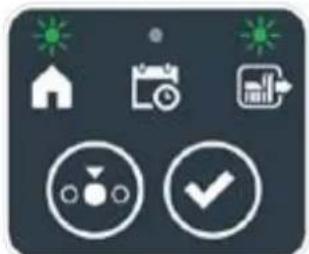
natural_image
Icon set with home, calendar, and checkmark symbols on dark background (no text or numbers)
Procédure :
text_image
A C D B
STOP
I L
E F G
text_image
A C D B
STOP
M
5.3.6. AFFICHAGE DES ÉTATS D'ALARME - ICÔNE ALARMES
text_image
A C D B
STOP
N
E
5.3.7. AFFICHAGE DE LA CHARGE DE LA BATTERIE - ICÔNE DE LA BATTERIE
natural_image
3D diagram of a device with a labeled component (N) and an inset showing a green button, no text or symbols present.
5.5. CHARGE DE LA BATTERIE
text_image
A C B R S
O
E
natural_image
Diagram of green grass with X and Y axis labels, no text or symbols present
Procédure :
text_image
A C D B
STOP
P Q
6. ENTRETIEN
6.1. ENTRETIEN PROGRAMMÉ
natural_image
Diagram of a robotic vehicle with labeled parts (D) and internal components, no readable text or symbols present.

text_image
Labeled diagram of a tracked vehicle showing key components: F, E, and G.
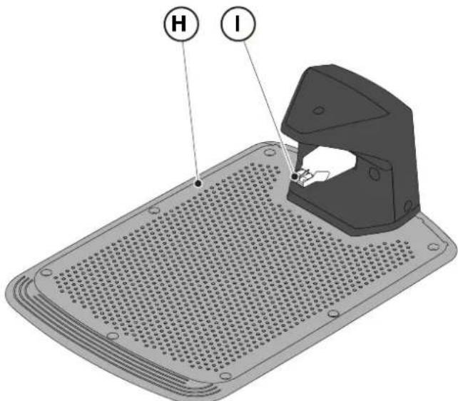
text_image
H
I
6.3. REMPLACEMENT DE LA LAME

text_image
Technical diagram of a robotic vehicle showing internal components and labeled parts (D, E, D)
6.4. ENTRETIEN D'HIVER DE LA BATTERIE ET STOCKAGE
Procédure :
natural_image
3D rendering of a gray robotic device with a black handle and circular base (no text or symbols visible)
6.5. REMPLACEMENT BATTERIE
(Supply of Machinery (Safety) Regulations 2008, S.I. 2008 No. 1597, Annex II, part A)
- The company: ST. S.p.A. – Via del Lavoro, 6 – 31033 Castelfranco Veneto (TV) – Italy
- Hereby declares under its own responsibility that the machine:
Robotic lawnmower
a) Homologation type: SRSW01
c) Serial number: 22A••RMO000001 ÷ 99L••RMO999999
d) Engine: battery-operated
- Conforms to UK Regulations:
• S.I. 2008/1597 - Supply of Machinery (Safety) Regulations 2008
• S.I. 2016/1091 - Electromagnetic Compatibility Regulations 2016
- S.I. 2012/3032 - The Restriction of the Use of Certain Hazardous Substances in Electrical and Electronic Equipment Regulations 2012
• S.I. 2017/1206 - Radio Equipment Regulations 2017
- Reference to harmonised standards:
EN 60335-1:2012 / AC:2014 / A11:2014 / A13:2017 / EN 61000-3-2:2019
A1:2019 / A2:2019 / A14:2019 EN 61000-3-3:2013 / A1:2019
EN IEC 63000:2018 EN 300 328 V2.2.2
EN 303 447 V1.2.0
EN 50636-107:2015 / A1 / A2
EN 301 489-17 V3.2.4
EN 62479:2010
EN 55014-1:2017 / A11:2020
EN 55014-2:2015
i) Cutting width: 18 cm
n) Person authorised to compile the technical file: ST. S.p.A.
Via del Lavoro, 6
31033 Castelfranco Veneto (TV) - Italia
o) Castelfranco Veneto, 01/12/2022 CEO Stiga Group
ST. S.p.A.
Via del Lavoro, 6
31033 Castelfranco Veneto (TV) - Italia
Sean Robinson

UK Importer:
STIGA LTD
Unit 8, Bluewater Estate Plympton,
Devon, PL7 4JH, England

| FR (Traduction de la notice originale)Déclaration CE de Conformité (Directive Machines 2006/42/CE, Annexe II, partie A)1. La Société2. Déclare sous sa propre responsabilité que la machine : Robot-tondeusea) Type / Modèle de Basec) Série d) Moteur: batterie3. Est conforme aux prescriptions des directives :4. Renvoi aux Normes harmoniséesi) Largeur de coupen) Personne habilitée à établir le Dossier Technique :o) Lieu et Date | DE (Übersetzung der Originalbetriebsanleitung)EG-Konformitätserklärung (Maschinenrichtlinie 2006/42/EG, Anhang II, Teil A)1. Die Gesellschaft2. Erklärt auf eigene Verantwortung, dass die Maschine: Mährobotera) Typ / Basismodellc) Seriennummerd) Motor: Batterie3. Den Anforderungen der folgenden Richtlinien entspricht:4. Bezugnahme auf die harmonisierten Normeni) Schnittbreiten) Zur Verfassung der technischen Unterlagen befugte Person:o) Ort und Datum | NL (Vertaling van de oorspronkelijke gebruiksaanwijzing)EG-verklaring van overeenstemming (Richtlijn Machines 2006/42/CE, Bijlage II, deel A)1. Het bedrijf2. Verklaart onder zijn eigen verantwoordelijkheid dat de machine: Robotmaaier a) Type / Basismodelc) Serienummerd) Motor: accu3. Voldoet aan de specificaties van der richtlijnen:4. Verwijzing naar de Geharmoniseerde normeni) Snijbreedten) Bevoegd persoon voor het opstellen van het Technisch Dossiero) Plaats en Datum |
| ES (Traducción del Manual Original)Declaración de Conformidad CE (Directiva Máquinas 2006/42/CE, Anexo II, parte A)1. La Empresa2. Declara bajo su propia responsabilidad que la máquina: Robot cortacéspeda) Tipo / Modelo Basec) Matrículad) Motor: bateria3. Cumple con las especificaciones de las directivas:4. Referencia a las Normas armonizadasi) Amplitud de corten) Persona autorizada a realizar el Manual Técnico:o) Lugar y Fecha | PT (Tradução do manual original)Declaração CE de Conformidade (Diretiva de Máquinas 2006/42/CE, Anexo II, parte A)1. A Empresa2. Declara sob a própria responsabilidade que a máquina: Robot corta-relva a) Tipo / Modelo Basec) Matrículad) Moto: Bateria3. É conforme às especificações das diretivas:4. Referência às Normas harmonizadasi) Amplitude de corten) Pessoa autorizada a elaborar o Caderno Técnicoo) Local e Data | NO (Oversettelse av original bruksanvisning)EF- Samvarserklæring (Maskindirektiv 2006/42/EF, Vedlegg II, del A)1. Firmaet2. Erklærer på eget ansvar at maskinen: Robotgressklippera) Type / Modellc) Serienummerd) Motor: batteri3. Oppfyller kravene i direktivene:4. Henvisning til harmoniserte standarderI) Klippebredden) Person som har fullmakt til å ufterdige teknisk dokumentasjon:o) Sted og dato |
| SV (Översättning av bruksanvisning i original)EG-försäkran om överensstämmelse (Maskindirektiv 2006/42//EG, bilaga II, dela)1. Företaget2. Försäkrar på eget ansvar att maskinen: Gräsklipparrobota) Typ / Basmodellc) Serienummerd) Motor: batteri3. Överensstämmer med föreskrifterna i direktivet4. Referens till harmoniserade standarderi) Skärbreddn) Auktoriserad person för upprättandet av den tekniska dokumentationen:o) Ort och datum | DA (Översættelse af den originale brugsanvisning)EF-overensstemmelseserklæring (Maskindirektiv 2006/42/EF, bilag II, del A)1. Firmaet2. Erklærer på eget ansvar, at maskinen: Robotplænekllippera) Type / Modelc) Serienummerd) Motor: batteri3. Er i overensstemmelse med specifikationerne ifølge direktiverne:4. Henvisning til harmoniserede standarderi) Klippebredden) Person, der har bemyndigelse til at udarbejde det tekniske dossier:o) Sted og dato | FI (Alkuperäisten ohjeiden käännös)EY-VAATIMUSTENMUKAISUUSVAKUUTUS (Konedirektiivi 2006/42/EY, Liite II, osa A)1. Yritys2. Vakuuttaa omalla vastuullaan, että kone: Robottiruohonlelikkurla) Tyyppl / Perusmalllc) Sarjanumerod) Moottori : akku3. On yhdenmukainen seuraavien direktiivien asettamien vaatimusten kanssa:4. Viittaus harmonisoituihin standardeihini) Leikkuuleveysn) Teknisten asiakirjojen laatimiseenvaltuutettu henkilö:o) Paikka ja päivämäärä |
| SL (Prevod izvirnih navodil)ES izjava o skladnosti (Direktiva 2006/42/ES) , priloga II, del A)1. Družba2. pod lastno odgovornostjo izjavlja, da je stroj: Robotska kosilnicaa) Tip / osnovni modelc) Serijska številkad) Motor: baterija3. Skladen je z določili direktiv :4. Sklicevanje na usklajene predpisei) Obseg košnjen) Oseba, pooblaščena za sestavotehnične knjižice:o) Kraj In datum | LT (Originalių instrukciju vertimas)EB atitikties deklaracija (Mašinų direktyva 2006/42/CE, Priedas II, dalis A)1. Bendrovė2. Prisilma atsakomybę, kad jrenglnys: Žolės pjovimo robotasa) Tipas / Bazinis Modelisc) Serijos numerisd) Variklis: baterija3. Atitinka direktyvose pateiktas specifikacijas:4. Nuoroda i suderintas Normasi) Pjovimo plotisn) Autorizuotas asmuo sudaryti Techninę Dokumentaciją:o) Vieta ir Data | LV (Instrukciju tulkojums no originálvalodas)EK atbilstības deklarācija (Direktīva 2006/42/EK par mašinām, pleilkums II, daļa A)1. Uzņēmums2. Uzņemoties par to pilnu atbildību, pazino, ka mašina: Robotizēta pljaujmašina a) Tips / Bāzes modelsc) Sērijas numursd) Motors: akumulators3. Atbilst šādu direktīvu prasībām:4. Atsauce uz harmonizētiem standartiemi) Pljaušanas platumsn) Pilnvarotais darbinieks, kas sagatavoja tehnisko dokumentāciju:o) Vieta un datums |
| CS (Překlad původního návodu k používání)ES – Prohlášení o shodě(Směrnice o Strojních zařízeních 2006/42/ES, Přiloha II, část A)1. Společnost2. Prohlášuje na vlastní odpovědnost, že stroj: Robotická sekačkaa) Typ / Základní modelc) Výrobní číslod) Motor: akumulátor3. Je ve shodě s nařízeními směrnic:4. Odkazy na Harmonizované normyi) Šířka řezánín) Osoba autorizovaná pro vytvoření Technického spisu:o) Misto a Datum | PL (Tłumaczenie instrukcji oryginalnej)Deklaracja zgodności WE(Dyrektywa maszynowa 2006/42/WE,Załącznik II, część A)1. Spółka2. Oświadczenie na własną odpowiedzialność, że maszyna: Kosiarka trawnikowaa) Typ / Model podstawowyc) Numer seryjnyd) Silnik: akumulator3. Spełnia podstawowe wymogi następujących Dyrektyw:4. Odniesienie do Norm zharmonizowanychi) Szerokość cięcia n) Osoba upoważniona do zredagowania Dokumentacji technicznej:o) Miejscowość i data | ET (Algupārase kasutusjuhendi tõlge)EÜ vastavusdeklaratsioon(Masinadirektiiv 2006/42/EÜ, Lisa II, osa A)1. Firma2. Kinnitab omal vastutusel, et masin:Robotniiduka) Tüüp / Põhimudel c) Matrikkeld) Mootor: aku3. Vastab direktiivide nõuetele:4. Viide ühtlustatud standarditelei) Lõikelaiusn) Tehnilise Lehe autoriseeritud koostaja:o) Koht ja Kuupäev |
| HU (Eredeti használati utasítás fordítása)EK-megfelelőségi nyilatkozata(2006/42/EK gépirányelv, ll. melléklet "A" rész)1. Alulírott Vállalat2. Felelősségének teljes tudatában kijelenti, hogy az alábbi gép: Robotfűnyíróa) Típus / Alaptipusc) Gyártási számd) Motor: akkumulátor3. Megfelel az alábbi irányelvekelőírásainak:4. Hivatkozás a harmonizált szabványokrai) Vágási szélességn) Műszaki Dosszié szerkesztésérefelhatalmazott személy:o) Helye és ideje | RU (Перевод оригинальных инструкций)Декларация соответствия нормам EC (Direktiva o машинном оборудовании 2006/42/EC, Приложение II, часть A)1. Предприятие2. Заявляет под собственную ответственность, что машина: Робот-газонокосилкаa) Тип / Базовая модельc) Паспортd) Двигатель: батарея сгорания3. Соответствует требованиям следующих директив:4. Ссылки на гармонизированные нормыi) Амплитуда кошенияn) Лицо, уполномоченное на подготовку технической документации:o) Место и дата | HR (Prijevod originalnih uputa)EK Izjava o sukladnosti(Direktiva 2006/42/EZ o strojevima, dodatak II, dio A)1. Tvrtka:2. pod vlastitom odgovornošću izjavljuje da je stroj: Robotska kosilicaa) Vrsta / Osnovni modelc) Matični brojd) Motor: baterija3. sukladan s temeljnim zahtjevima direktiva:4. Primijenjene su slijedeće harmonizirane norme:i) Širina rezanján) Osoba ovlaštena za pravljenje Tehničke datoteke:o) Mjesto i datum |
| SR (Prevod originalnih uputstval)EC deklaracija o usaglašenosti (Direktiva o mašinama 2006/42/EC, Prilog II, deo A)1. Preduzeće2. Daje izjavu pod vlastitom odgovornošćuda je mašina: Robot kosačicaa) Tip / Osnovni modelc) Serijski brojd) Motor: akumulator3. U skladu s osnovnim zahtevima direktiva:4. Pozivanje na usklađene normei) Širina košenjan) Osoba ovlašćena za sastavljanje tehničke brošureo) Mesto i datum | TR (Orijinal Talimatların Tercümesi)AT Uygunluk Beyanı (2006/42/CE Makine Direktifi, Ek II, bölüm A)1. Şirket2. Şahsi sorumluluğu altında aşağıdaki makinenin: Robot çim biçme makinesia) Tip / Standart modelc) Sicil numarasıd) Motor : batarya3. Aşağıdaki direktiflerin özelliklerine uygun olduğunu beyan etmektedir:4. Harmonize standartlara atifi) Kesim genişligiń) Teknik Dosyayı oluşturmaya yetkili kişi:o) Yer ve Tarih | RO (Traducerea manualului fabricantului)CE -Declaratie de Conformitate (Directiva Mašini 2006/42/CE, Anexa II, partea A)1. Societatea2. Declară pe propria răspundere că mașina: Robot mașină de tuns iarbaa) Tip / Model de bazăc) Număr de seried) Motor: baterie3. Este în conformitate cu specificațiile directivelor:4. Referință la Standardele armonizatei) Lătimea de täieren) Persoană autorizată să întocmeascăDosarul Tehnico) Locul și Data |
STIGA
STIGA LTD (UK Importer)
Unit 8, Bluewater Estate Plympton, Devon, PL7 4JH, England
STIGA S.p.A.
Via del lavoro, 6
31033 Castelfranco Veneto (TV)
Italy
stiga.com

FR
natural_image
Two yellow and gray STIGA robotic vacuum cleaner units (no visible text or symbols)
natural_image
Line drawing of a mounted robotic vacuum cleaner (no text or symbols)

natural_image
Technical line drawing of a tracked robotic vehicle showing internal components and mounting hardware (no text or symbols)
text_image
Diagram illustrating a robotic device (A) and its corresponding layout with labeled components including camera, sensor, and display areas.
3.2.2. HAUPTBESTANDTEILE
natural_image
Diagram of a battery pack and its circuit board with labeled components (no text or symbols present)
text_image
Diagram showing four labeled components: coiled wire, plastic cup with pins, mechanical component, and plastic clamp.
3.3. AUSPACKVORGANG
text_image
Safety warning signs and robot diagram with Chinese labels for hazard, safety, vehicle, and pictograms

ACHTUNG:
text_image
Diagram showing four symbols: battery pack, recycling symbol, no-renewable waste bin, and water-related warning sign.

ACHTUNG:
text_image
Diagram showing labeled components of a mechanical or electrical device, including an iron iron, cable, and screw assembly.
text_image
Diagram illustrating electrical grounding setup with labeled components A, B, C and distance markers x and x̄

ACHTUNG:
text_image
Diagram showing a device mounted on a wall with a ruler and a mouse, labeled with dimension 'X' and figure marker (B)
text_image
Diagram illustrating plant growth in a pond with labeled points G and F, showing green plants and water levels.
text_image
F
D
x3
F
E
x3
STIGA
text_image
O
P
M
x6
O
P
N
x6

WARNUNG:
natural_image
Illustration of a robotic device and tree trunk with labeled parts (Z and V), no text or symbols present.
text_image
A
R=20 cm

text_image
B
100 cm
ERDVERLEGUNG
(KANN NUR VON EINEM AUTORISIERTEN HÄNDLER DURCHGEFÜHRT WERDEN)
text_image
Diagram illustrating the process of hairpin tool application, showing steps from cutting to holding a hairpin.
STIGA
text_image
Technical diagram of a mechanical assembly with labeled parts including screw, plate, and housing components
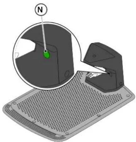
natural_image
3D diagram of a mechanical device with a green indicator light and a magnified view showing a component (no text or symbols)
natural_image
Diagram of a red electrical fuse with a circular component labeled 'O' (no text or symbols beyond the label)

text_image
D2
C
O
I
E2E2
| G 300 G 600 G | 1200 | |
| Border Cut |  |  |  |
| Go-To Cut Points | 1 3 5 | | |
| Eco Mode |  |  |  |
| Rain Sensor |  |  |  |
| Closed Area |  |  |  |
text_image
B
D
E
C
STOP
A
5.2. MANUELLER BETRIEB DES MÄHROBOTERS
text_image
A C D B
STOP
L
E F G
text_image
A C D B
STOP
O H I L N
E F G M
text_image
A C D B
STOP
E
natural_image
Icon set with home, calendar, and checkmark symbols (no text or numbers)

natural_image
Icon set with home, calendar, and checkmark symbols (no text or numbers)

natural_image
Icon set with home, calendar, and checkmark symbols (no text or numbers)

natural_image
Icon set with home, calendar, and checkmark symbols (no text or numbers)

natural_image
Icon set with home, camera, and checklist symbols (no text or numbers)
STIGA
Verfahren:
text_image
A C D B
STOP
I L
E F G
text_image
Mntr. (Clone Rap. 1)
N
text_image
A C B R S
O
E
natural_image
Diagram showing two green grasses with X and Y axis labels (no text or symbols on the grass itself)
Verfahren:
text_image
A C D B
STOP
P Q
6. WARTUNG
natural_image
Diagram of a robotic vehicle showing internal components and a labeled point D (no text or symbols present)

ACHTUNG:
text_image
Labeled diagram of a tracked vehicle showing components F, E, and G with visible parts and structural details.
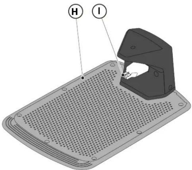
text_image
H
I
text_image
Technical diagram of a robotic car showing internal components and labeled parts (D, E, D)
natural_image
3D rendering of a robotic vacuum cleaner with a circular vent and handle (no text or symbols visible)
(Supply of Machinery (Safety) Regulations 2008, S.I. 2008 No. 1597, Annex II, part A)
- The company: ST. S.p.A. – Via del Lavoro, 6 – 31033 Castelfranco Veneto (TV) – Italy
- Hereby declares under its own responsibility that the machine:
Robotic lawnmower
a) Homologation type: SRSW01
c) Serial number: 22A••RMO000001 ÷ 99L••RMO999999
d) Engine: battery-operated
- Conforms to UK Regulations:
• S.I. 2008/1597 - Supply of Machinery (Safety) Regulations 2008
• S.I. 2016/1091 - Electromagnetic Compatibility Regulations 2016
• S.I. 2012/3032 - The Restriction of the Use of Certain Hazardous Substances in Electrical and Electronic Equipment Regulations 2012
• S.I. 2017/1206 - Radio Equipment Regulations 2017
- Reference to harmonised standards:
EN 60335-1:2012 / AC:2014 / A11:2014 / A13:2017 / EN 61000-3-2:2019
A1:2019 / A2:2019 / A14:2019 EN 61000-3-3:2013 / A1:2019
EN IEC 63000:2018 EN 300 328 V2.2.2
EN 303 447 V1.2.0
EN 50636-107:2015 / A1 / A2
EN 301 489-17 V3.2.4
EN 62479:2010
EN 55014-1:2017 / A11:2020
EN 55014-2:2015
i) Cutting width: 18 cm
n) Person authorised to compile the technical file: ST. S.p.A.
Via del Lavoro, 6
31033 Castelfranco Veneto (TV) - Italia
o) Castelfranco Veneto, 01/12/2022 CEO Stiga Group
Sean Robinson

UK Importer:
STIGA LTD
Unit 8, Bluewater Estate Plympton,
Devon, PL7 4JH, England

| FR (Traduction de la notice originale)Déclaration CE de Conformité (Directive Machines 2006/42/CE, Annexe II, partie A)1. La Société2. Déclare sous sa propre responsabilité que la machine : Robot-tondeusea) Type / Modèle de Basec) Série d) Moteur: batterie3. Est conforme aux prescriptions des directives :4. Renvoi aux Normes harmoniséesi) Largeur de coupen) Personne habilitée à établir le Dossier Technique :o) Lieu et Date | DE (Übersetzung der Originalbetriebsanleitung)EG-Konformitätserklärung (Maschinenrichtlinie 2006/42/EG, Anhang II, Teil A)1. Die Gesellschaft2. Erklärt auf eigene Verantwortung, dass die Maschine: Mährobotera) Typ / Basismodellc) Seriennummerd) Motor: Batterie3. Den Anforderungen der folgenden Richtlinien entspricht:4. Bezugnahme auf die harmonisierten Normeni) Schnittbreiten) Zur Verfassung der technischen Unterlagen befugte Person:o) Ort und Datum | NL (Vertaling van de oorspronkelijke gebruiksaanwijzing)EG-verklaring van overeenstemming (Richtlijn Machines 2006/42/CE, Bijlage II, deel A)1. Het bedrijf2. Verklaart onder zijn eigen verantwoordelijkheid dat de machine: Robotmaaier a) Type / Basismodelc) Serienummerd) Motor: accu3. Voldoet aan de specificaties van der richtlijnen:4. Verwijzing naar de Geharmoniseerde normeni) Snijbreedten) Bevoegd persoon voor het opstellen van het Technisch Dossiero) Plaats en Datum |
| ES (Traducción del Manual Original)Declaración de Conformidad CE (Directiva Máquinas 2006/42/CE, Anexo II, parte A)1. La Empresa2. Declara bajo su propia responsabilidad que la máquina: Robot cortacéspeda) Tipo / Modelo Basec) Matrículad) Motor: bateria3. Cumple con las especificaciones de las directivas:4. Referencia a las Normas armonizadasi) Amplitud de corten) Persona autorizada a realizar el Manual Técnico:o) Lugar y Fecha | PT (Tradução do manual original)Declaração CE de Conformidade (Diretiva de Máquinas 2006/42/CE, Anexo II, parte A)1. A Empresa2. Declara sob a própria responsabilidade que a máquina: Robot corta-relva a) Tipo / Modelo Basec) Matrículad) Moto: Bateria3. É conforme às especificações das diretivas:4. Referência às Normas harmonizadasi) Amplitude de corten) Pessoa autorizada a elaborar o Caderno Técnicoo) Local e Data | NO (Oversettelse av original bruksanvisning)EF- Samvarserklæring (Maskindirektiv 2006/42/EF, Vedlegg II, del A)1. Firmaet2. Erklærer på eget ansvar at maskinen: Robotgressklippera) Type / Modellc) Serienummerd) Motor: batteri3. Oppfyller kravene i direktivene:4. Henvisning til harmoniserte standarderI) Klippebredden) Person som har fullmakt til å ufterdige teknisk dokumentasjon:o) Sted og dato |
| SV (Översättning av bruksanvisning i original)EG-försäkran om överensstämmelse (Maskindirektiv 2006/42//EG, bilaga II, dela)1. Företaget2. Försäkrar på eget ansvar att maskinen: Gräsklipparrobota) Typ / Basmodellc) Serienummerd) Motor: batteri3. Överensstämmer med föreskrifterna i direktivet4. Referens till harmoniserade standarderi) Skärbreddn) Auktoriserad person för upprättandet av den tekniska dokumentationen:o) Ort och datum | DA (Översættelse af den originale brugsanvisning)EF-overensstemmelseserklæring (Maskindirektiv 2006/42/EF, bilag II, del A)1. Firmaet2. Erklærer på eget ansvar, at maskinen: Robotplænekllippera) Type / Modelc) Serienummerd) Motor: batteri3. Er i overensstemmelse med specifikationerne ifølge direktiverne:4. Henvisning til harmoniserede standarderi) Klippebredden) Person, der har bemyndigelse til at udarbejde det tekniske dossier:o) Sted og dato | FI (Alkuperäisten ohjeiden käännös)EY-VAATIMUSTENMUKAISUUSVAKUUTUS (Konedirektiivi 2006/42/EY, Liite II, osa A)1. Yritys2. Vakuuttaa omalla vastuullaan, että kone: Robottiruohonlelikkurla) Tyyppl / Perusmalllc) Sarjanumerod) Moottori : akku3. On yhdenmukainen seuraavien direktiivien asettamien vaatimusten kanssa:4. Viittaus harmonisoituihin standardeihini) Leikkuuleveysn) Teknisten asiakirjojen laatimiseenvaltuutettu henkilö:o) Paikka ja päivämäärä |
| SL (Prevod izvirnih navodil)ES izjava o skladnosti (Direktiva 2006/42/ES) , priloga II, del A)1. Družba2. pod lastno odgovornostjo izjavlja, da je stroj: Robotska kosilnicaa) Tip / osnovni modelc) Serijska številkad) Motor: baterija3. Skladen je z določili direktiv :4. Sklicevanje na usklajene predpisei) Obseg košnjen) Oseba, pooblaščena za sestavotehnične knjižice:o) Kraj In datum | LT (Originalių instrukciju vertimas)EB atitikties deklaracija (Mašinų direktyva 2006/42/CE, Priedas II, dalis A)1. Bendrovė2. Prisilma atsakomybę, kad jrenglnys: Žolės pjovimo robotasa) Tipas / Bazinis Modelisc) Serijos numerisd) Variklis: baterija3. Atitinka direktyvose pateiktas specifikacijas:4. Nuoroda i suderintas Normasi) Pjovimo plotisn) Autorizuotas asmuo sudaryti Techninę Dokumentaciją:o) Vieta ir Data | LV (Instrukciju tulkojums no originálvalodas)EK atbilstības deklarācija (Direktīva 2006/42/EK par mašinām, pleilkums II, daļa A)1. Uzņēmums2. Uzņemoties par to pilnu atbildību, pazino, ka mašina: Robotizēta pljaujmašina a) Tips / Bāzes modelsc) Sērijas numursd) Motors: akumulators3. Atbilst šādu direktīvu prasībām:4. Atsauce uz harmonizētiem standartiemi) Pljaušanas platumsn) Pilnvarotais darbinieks, kas sagatavoja tehnisko dokumentāciju:o) Vieta un datums |
| CS (Překlad původního návodu k používání)ES – Prohlášení o shodě(Směrnice o Strojních zařízeních 2006/42/ES, Přiloha II, část A)1. Společnost2. Prohlášuje na vlastní odpovědnost, že stroj: Robotická sekačkaa) Typ / Základní modelc) Výrobní číslod) Motor: akumulátor3. Je ve shodě s nařízeními směrnic:4. Odkazy na Harmonizované normyi) Šířka řezánín) Osoba autorizovaná pro vytvoření Technického spisu:o) Misto a Datum | PL (Tłumaczenie instrukcji oryginalnej)Deklaracja zgodności WE(Dyrektywa maszynowa 2006/42/WE,Załącznik II, część A)1. Spółka2. Oświadczenie na własną odpowiedzialność, że maszyna: Kosiarka trawnikowaa) Typ / Model podstawowyc) Numer seryjnyd) Silnik: akumulator3. Spełnia podstawowe wymogi następujących Dyrektyw:4. Odniesienie do Norm zharmonizowanychi) Szerokość cięcia n) Osoba upoważniona do zredagowania Dokumentacji technicznej:o) Miejscowość i data | ET (Algupārase kasutusjuhendi tõlge)EÜ vastavusdeklaratsioon(Masinadirektiiv 2006/42/EÜ, Lisa II, osa A)1. Firma2. Kinnitab omal vastutusel, et masin:Robotniiduka) Tüüp / Põhimudel c) Matrikkeld) Mootor: aku3. Vastab direktiivide nõuetele:4. Viide ühtlustatud standarditelei) Lõikelaiusn) Tehnilise Lehe autoriseeritud koostaja:o) Koht ja Kuupäev |
| HU (Eredeti használati utasítás fordítása)EK-megfelelőségi nyilatkozata(2006/42/EK gépirányelv, ll. melléklet "A" rész)1. Alulírott Vállalat2. Felelősségének teljes tudatában kijelenti, hogy az alábbi gép: Robotfűnyíróa) Típus / Alaptipusc) Gyártási számd) Motor: akkumulátor3. Megfelel az alábbi irányelvekelőírásainak:4. Hivatkozás a harmonizált szabványokrai) Vágási szélességn) Műszaki Dosszié szerkesztésérefelhatalmazott személy:o) Helye és ideje | RU (Перевод оригинальных инструкций)Декларация соответствия нормам EC (Direktiva o машинном оборудовании 2006/42/EC, Приложение II, часть A)1. Предприятие2. Заявляет под собственную ответственность, что машина: Робот-газонокосилкаa) Тип / Базовая модельc) Паспортd) Двигатель: батарея сгорания3. Соответствует требованиям следующих директив:4. Ссылки на гармонизированные нормыi) Амплитуда кошенияn) Лицо, уполномоченное на подготовку технической документации:o) Место и дата | HR (Prijevod originalnih uputa)EK Izjava o sukladnosti(Direktiva 2006/42/EZ o strojevima, dodatak II, dio A)1. Tvrtka:2. pod vlastitom odgovornošću izjavljuje da je stroj: Robotska kosilicaa) Vrsta / Osnovni modelc) Matični brojd) Motor: baterija3. sukladan s temeljnim zahtjevima direktiva:4. Primijenjene su slijedeće harmonizirane norme:i) Širina rezanján) Osoba ovlaštena za pravljenje Tehničke datoteke:o) Mjesto i datum |
| SR (Prevod originalnih uputstval)EC deklaracija o usaglašenosti (Direktiva o mašinama 2006/42/EC, Prilog II, deo A)1. Preduzeće2. Daje izjavu pod vlastitom odgovornošćuda je mašina: Robot kosačicaa) Tip / Osnovni modelc) Serijski brojd) Motor: akumulator3. U skladu s osnovnim zahtevima direktiva:4. Pozivanje na usklađene normei) Širina košenjan) Osoba ovlašćena za sastavljanje tehničke brošureo) Mesto i datum | TR (Orijinal Talimatların Tercümesi)AT Uygunluk Beyanı (2006/42/CE Makine Direktifi, Ek II, bölüm A)1. Şirket2. Şahsi sorumluluğu altında aşağıdaki makinenin: Robot çim biçme makinesia) Tip / Standart modelc) Sicil numarasıd) Motor : batarya3. Aşağıdaki direktiflerin özelliklerine uygun olduğunu beyan etmektedir:4. Harmonize standartlara atifi) Kesim genişligiń) Teknik Dosyayı oluşturmaya yetkili kişi:o) Yer ve Tarih | RO (Traducerea manualului fabricantului)CE -Declaratie de Conformitate (Directiva Mašini 2006/42/CE, Anexa II, partea A)1. Societatea2. Declară pe propria răspundere că mașina: Robot mașină de tuns iarbaa) Tip / Model de bazăc) Număr de seried) Motor: baterie3. Este în conformitate cu specificațiile directivelor:4. Referință la Standardele armonizatei) Lătimea de täieren) Persoană autorizată să întocmeascăDosarul Tehnico) Locul și Data |
STIGA
STIGA LTD (UK Importer)
Unit 8, Bluewater Estate Plympton, Devon, PL7 4JH, England
STIGA S.p.A.
Via del lavoro, 6
31033 Castelfranco Veneto (TV)
Italy

FR
natural_image
Two yellow and gray TIGA robotic vacuum cleaner units (no visible text or symbols)
natural_image
Technical line drawings of a two-part robotic device (ATGA) showing internal components and mounting features, no text or symbols present.
1.2. DATI TECNICI
natural_image
Technical diagram showing two components: a mechanical housing labeled D and a rectangular device labeled E connected by wires (no text or symbols beyond labels)
text_image
Diagram showing four labeled components: coiled wire, cap with pins, mechanical component, and plastic clamp.
3.3. DISIMBALLAGGIO
text_image
Safety warning signs and a robotic device with Chinese labels, including warning symbols for accidents, safety measures, and pictograms.

ATTENZIONE:
text_image
Diagram showing four symbols: battery pack, recycling symbol, no-renewable waste bin, and water-related warning sign.

ATTENZIONE:
text_image
Diagram showing labeled components of a mechanical or electrical device, including a iron shaver, coiled cable, and various screw and nut parts.
4.3. VERIFICA DEI REQUISITI PER L'INSTALLAZIONE
text_image
Diagram illustrating a mechanical or electrical setup with labeled components A, B, C and directional arrows indicating paths and distances.

ATTENZIONE:
text_image
Diagram showing a device mounted on a wall with a ruler and a mouse, labeled with dimension 'X' and figure marker (B)
text_image
Diagram illustrating plant growth in a pond with labeled points G and F, showing green plants and water level.
4.4. CRITERI PER L'INSTALLAZIONE DEL CAVO PERIMETRALE
text_image
F
D
x3
F
E
x3
STIGA
text_image
O
P
M
x6
O
P
N
x6

AVVERTENZA:
flowchart
graph TD
    A["Central Rectangle"] --> B["Laptop"]
    B --> C["Light Grey Box"]
    C --> D["Square"]
    D --> E["Square"]
    E --> F["Circle"]
    F --> G["Circle"]
    G --> H["Circle"]
    H --> I["Circle"]
    I --> J["Circle"]
    J --> K["Circle"]
    K --> L["Circle"]
    L --> M["Circle"]
    M --> N["Circle"]
    N --> O["Circle"]
    O --> P["Circle"]
    P --> Q["Circle"]
    Q --> R["Circle"]
    R --> S["Circle"]
    S --> T["Circle"]
    T --> U["Circle"]
    U --> V["Circle"]
    V --> W["Circle"]
    W --> X["Circle"]
    X --> Y["Circle"]
    Y --> Z["Circle"]
natural_image
Illustration of a robotic vacuum cleaner and tree trunk with labeled parts (Z and V), no text or symbols present.
4.4.3. PASSAGGI TRA DIVERSE ZONE DEL GIARDINO
Procedura:
text_image
A
R=20 cm
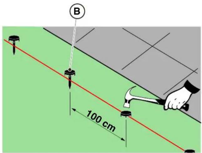
text_image
B
100 cm
text_image
Diagram illustrating the process of hairpin tool application, showing steps from pinning to cutting and holding a hairpin.
STIGA
text_image
Technical diagram of a mechanical assembly with labeled parts L, C, and M, showing screw installation and component layout.

natural_image
3D diagram of a mechanical device with a green indicator light and a magnified view showing internal components (no text or symbols)
natural_image
Diagram of a red electrical fuse with a circular component labeled 'O' (no text or symbols beyond the label)

text_image
D2
C
O
I
E2E2
4.6. RICARICA ROBOT RASAERBA DOPO L'INSTALLAZIONE
| G 300 G 600 G | 1200 | |
| Border Cut |  |  |  |
| Go-To Cut Points | 1 3 5 | | |
| Eco Mode |  |  |  |
| Rain Sensor |  |  |  |
| Closed Area |  |  |  |
text_image
A
B
C
D
E
STOP
text_image
A C D B
STOP
L
E F G
text_image
A C D B
STOP
O H I L N
E F G M
5.3.1. ARRESTO IN SICUREZZA - PULSANTE STOP
text_image
A C D B
STOP
E
5.3.4. SELEZIONE PROGRAMMA SCHEDULATO / SINGOLO CICLO DI LAVORO / RITORNO FORZATO IN BASE DI RICARICA - PULSANTE SELEZIONE MODALITÀ
natural_image
Icon set with home, calendar, and checkmark symbols (no text or numbers)

natural_image
Icon set with home, calendar, and checkmark symbols (no text or numbers)

natural_image
Icon set with home, calendar, and checkmark symbols (no text or numbers)

natural_image
Icon set with home, calendar, and checkmark symbols on dark background (no text or numbers)
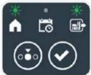
natural_image
Icon set with home, camera, and checklist symbols (no text or numbers)
STIGA
Procedura:
text_image
A C D B
STOP
I L
E F G
text_image
A C D B
STOP
M
text_image
A C D B
STOP
N
E
natural_image
3D diagram of a device with a mesh base and a magnified inset showing a green indicator finger pointing to a component labeled 'N' (no text or symbols on the main diagram)
text_image
A C B R S
O
E
natural_image
Diagram of green grasses with X and Y axis labels (no text or symbols on the grass itself)
Procedura:
text_image
A C D B
STOP
P Q
6. MANUTENZIONE
6.1. MANUTENZIONE PROGRAMMATA
natural_image
Diagram of a robotic vehicle showing internal components and a labeled point D (no text or symbols present)

ATTENZIONE:
text_image
Labeled diagram of a tracked vehicle showing components F, E, and G with visible parts and motion indicators.

text_image
H
I
text_image
Technical diagram of a robotic vehicle showing internal components and labeled parts (D, E, D)
natural_image
3D rendering of a gray robotic device with a black handle and circular base (no text or symbols visible)
(Supply of Machinery (Safety) Regulations 2008, S.I. 2008 No. 1597, Annex II, part A)
- The company: ST. S.p.A. – Via del Lavoro, 6 – 31033 Castelfranco Veneto (TV) – Italy
- Hereby declares under its own responsibility that the machine:
Robotic lawnmower
a) Homologation type: SRSW01
c) Serial number: 22A••RMO000001 ÷ 99L••RMO999999
d) Engine: battery-operated
- Conforms to UK Regulations:
• S.I. 2008/1597 - Supply of Machinery (Safety) Regulations 2008
• S.I. 2016/1091 - Electromagnetic Compatibility Regulations 2016
• S.I. 2012/3032 - The Restriction of the Use of Certain Hazardous Substances in Electrical and Electronic Equipment Regulations 2012
• S.I. 2017/1206 - Radio Equipment Regulations 2017
- Reference to harmonised standards:
EN 60335-1:2012 / AC:2014 / A11:2014 / A13:2017 / EN 61000-3-2:2019
A1:2019 / A2:2019 / A14:2019 EN 61000-3-3:2013 / A1:2019
EN IEC 63000:2018 EN 300 328 V2.2.2
EN 303 447 V1.2.0
EN 50636-107:2015 / A1 / A2
EN 301 489-17 V3.2.4
EN 62479:2010
EN 55014-1:2017 / A11:2020
EN 55014-2:2015
i) Cutting width: 18 cm
n) Person authorised to compile the technical file: ST. S.p.A.
Via del Lavoro, 6
31033 Castelfranco Veneto (TV) - Italia
o) Castelfranco Veneto, 01/12/2022 CEO Stiga Group
ST. S.p.A.
Via del Lavoro, 6
31033 Castelfranco Veneto (TV) - Italia
Sean Robinson

UK Importer:
STIGA LTD
Unit 8, Bluewater Estate Plympton,
Devon, PL7 4JH, England

| FR (Traduction de la notice originale)Déclaration CE de Conformité(Directive Machines 2006/42/CE, Annexe II, partie A)1. La Société2. Déclare sous sa propre responsabilité que la machine : Robot-tondeusea) Type / Modèle de Basec) Série d) Moteur: batterie3. Est conforme aux prescriptions des directives :4. Renvoi aux Normes harmoniséesi) Largeur de coupen) Personne habilitée à établir le Dossier Technique :o) Lieu et Date | DE (Übersetzung der Originalbetriebsanleitung)EG-Konformitätserklärung(Maschinenrichtlinie 2006/42/EG, Anhang II, Teil A)1. Die Gesellschaft2. Erklärt auf eigene Verantwortung, dass die Maschine: Mährobotera) Typ / Basismodellc) Seriennummerd) Motor: Batterie3. Den Anforderungen der folgenden Richtlinien entspricht:4. Bezugnahme auf die harmonisierten Normeni) Schnittbreiten) Zur Verfassung der technischen Unterlagen befugte Person:o) Ort und Datum | NL (Vertaling van de oorspronkelijke gebruiksaanwijzing)EG-verklaring van overeenstemming(Richtlijn Machines 2006/42/CE, Bijlage II, deel A)1. Het bedrijf2. Verklaart onder zijn eigen verantwoordelijkheid dat de machine: Robotmaaiera) Type / Basismodelc) Serienummerd) Motor: accu3. Voldoet aan de specificaties van der richtlijnen:4. Verwijzing naar de Geharmoniseerde normeni) Snijbreedten) Bevoegd persoon voor het opstellen van het Technisch Dossiero) Plaats en Datum |
| ES (Traducción del Manual Original)Declaración de Conformidad CE(Directiva Máquinas 2006/42/CE, Anexo II, parte A)1. La Empresa2. Declara bajo su propia responsabilidad que la máquina: Robot cortacéspeda) Tipo / Modelo Basec) Matrículad) Motor: bateria3. Cumple con las especificaciones de las directivas:4. Referencia a las Normas armonizadasi) Amplitud de corten) Persona autorizada a realizar el Manual Técnico:o) Lugar y Fecha | PT (Tradução do manual original)Declaração CE de Conformidade(Diretiva de Máquinas 2006/42/CE, Anexo II, parte A)1. A Empresa2. Declara sob a própria responsabilidade que a máquina: Robot corta-relvaa) Tipo / Modelo Basec) Matrículad) Moto: Bateria3. É conforme às especificações das diretivas:4. Referência às Normas harmonizadasi) Amplitude de corten) Pessoa autorizada a elaborar o Caderno Técnicoo) Local e Data | NO (Oversettelse av original bruksanvisning)EF- Samvarserklæring(Maskindirektiv 2006/42/EF, Vedlegg II, del A)1. Firmaet2. Erklærer på eget ansvar at maskinen: Robotgressklippera) Type / Modellc) Serienummerd) Motor: batteri3. Oppfyller kravene i direktivene:4. Henvisning til harmoniserte standarderI) Klippebredden) Person som har fullmakt til å ufterdige teknisk dokumentasjon:o) Sted og dato |
| SV (Översättning av bruksanvisning i original)EG-försäkran om överensstämmelse (Maskindirektiv 2006/42//EG, bilaga II, dela)1. Företaget2. Försäkrar på eget ansvar att maskinen: Gräsklipparrobota) Typ / Basmodellc) Serienummerd) Motor: batteri3. Överensstämmer med föreskrifterna i direktivet4. Referens till harmoniserade standarderi) Skärbreddn) Auktoriserad person för upprättandet av den tekniska dokumentationen:o) Ort och datum | DA (Översættelse af den originale brugsanvisning)EF-overensstemmelseserklæring(Maskindirektiv 2006/42/EF, bilag II, del A)1. Firmaet2. Erklærer på eget ansvar, at maskinen: Robotplænekllippera) Type / Modelc) Serienummerd) Motor: batteri3. Er i overensstemmelse med specifikationerne ifølge direktiverne:4. Henvisning til harmoniserede standarderi) Klippebredden) Person, der har bemyndigelse til at udarbejde det tekniske dossier:o) Sted og dato | FI (Alkuperäisten ohjeiden käännös)EY-VAATIMUSTENMUKAISUUSVAKUUTUS(Konedirektiivi 2006/42/EY, Liite II, osa A)1. Yritys2. Vakuuttaa omalla vastuullaan, että kone: Robottiruohonlelikkurla) Tyyppl / Perusmalllc) Sarjanumerod) Moottori : akku3. On yhdenmukainen seuraavien direktiivien asettamien vaatimusten kanssa:4. Viittaus harmonisoituihin standardeihini) Leikkuuleveysn) Teknisten asiakirjojen laatimiseenvaltuutettu henkilö:o) Paikka ja päivämäärä |
| SL (Prevod izvirnih navodil)ES izjava o skladnosti (Direktiva 2006/42/ES) , priloga II, del A)1. Družba2. pod lastno odgovornostjo izjavlja, da je stroj: Robotska kosilnicaa) Tip / osnovni modelc) Serijska številkad) Motor: baterija3. Skladen je z določili direktiv :4. Sklicevanje na usklajene predpisei) Obseg košnjen) Oseba, pooblaščena za sestavotehnične knjižice:o) Kraj In datum | LT (Originalių instrukciju vertimas)EB atitikties deklaracija (Mašinų direktyva 2006/42/CE, Priedas II, dalis A)1. Bendrovė2. Prisilma atsakomybę, kad jrenglnys: Žolės pjovimo robotasa) Tipas / Bazinis Modelisc) Serijos numerisd) Variklis: baterija3. Atitinka direktyvose pateiktas specifikacijas:4. Nuoroda i suderintas Normasi) Pjovimo plotisn) Autorizuotas asmuo sudaryti Techninę Dokumentaciją:o) Vieta ir Data | LV (Instrukciju tulkojums no originálvalodas)EK atbilstības deklarācija (Direktīva 2006/42/EK par mašinām, pleilkums II, daļa A)1. Uzņēmums2. Uzņemoties par to pilnu atbildību, pazino, ka mašina: Robotizēta pljaujmašinaa) Tips / Bāzes modelsc) Sērijas numursd) Motors: akumulators3. Atbilst šādu direktīvu prasībām:4. Atsauce uz harmonizētiem standartiemi) Plaušanas platumsn) Pilnvarotais darbinieks, kas sagatavoja tehnisko dokumentāciju:o) Vieta un datums |
| CS (Překlad původního návodu k používání)ES – Prohlášení o shodě(Směrnice o Strojních zařízeních 2006/42/ES, Přiloha II, část A)1. Společnost2. Prohlášuje na vlastní odpovědnost, že stroj: Robotická sekačkaa) Typ / Základní modelc) Výrobní číslod) Motor: akumulátor3. Je ve shodě s nařízeními směrnic:4. Odkazy na Harmonizované normyi) Šířka řezánín) Osoba autorizovaná pro vytvoření Technického spisu:o) Misto a Datum | PL (Tłumaczenie instrukcji oryginalnej)Deklaracja zgodności WE(Dyrektywa maszynowa 2006/42/WE,Załącznik II, część A)1. Spółka2. Oświadczenie na własną odpowiedzialność, że maszyna: Kosiarka trawnikowaa) Typ / Model podstawowyc) Numer seryjnyd) Silnik: akumulator3. Spełnia podstawowe wymogi następujących Dyrektyw:4. Odniesienie do Norm zharmonizowanychi) Szerokość cięcia n) Osoba upoważniona do zredagowania Dokumentacji technicznej:o) Miejscowość i data | ET (Algupārase kasutusjuhendi tõlge)EÜ vastavusdeklaratsioon(Masinadirektiiv 2006/42/EÜ, Lisa II, osa A)1. Firma2. Kinnitab omal vastutusel, et masin:Robotniiduka) Tüüp / Põhimudel c) Matrikkeld) Mootor: aku3. Vastab direktiivide nõuetele:4. Viide ühtlustatud standarditelei) Lõikelaiusn) Tehnilise Lehe autoriseeritud koostaja:o) Koht ja Kuupäev |
| HU (Eredeti használati utasítás fordítása)EK-megfelelőségi nyilatkozata(2006/42/EK gépirányelv, ll. melléklet "A" rész)1. Alulírott Vállalat2. Felelősségének teljes tudatában kijelenti, hogy az alábbi gép: Robotfűnyíróa) Típus / Alaptipusc) Gyártási számd) Motor: akkumulátor3. Megfelel az alábbi irányelvekelőírásainak:4. Hivatkozás a harmonizált szabványokrai) Vágási szélességn) Műszaki Dosszié szerkesztésérefelhatalmazott személy:o) Helye és ideje | RU (Перевод оригинальных инструкций)Декларация соответствия нормам EC (Direktiva o машинном оборудовании 2006/42/EC, Приложение II, часть A)1. Предприятие2. Заявляет под собственную ответственность, что машина: Робот-газонокосилкаa) Тип / Базовая модельc) Паспортd) Двигатель: батарея сгорания3. Соответствует требованиям следующих директив:4. Ссылки на гармонизированные нормыi) Амплитуда кошенияn) Лицо, уполномоченное на подготовку технической документации:o) Место и дата | HR (Prijevod originalnih uputa)EK Izjava o sukladnosti(Direktiva 2006/42/EZ o strojevima, dodatak II, dio A)1. Tvrtka:2. pod vlastitom odgovornošću izjavljuje da je stroj: Robotska kosilicaa) Vrsta / Osnovni modelc) Matični brojd) Motor: baterija3. sukladan s temeljnim zahtjevima direktiva:4. Primijenjene su slijedeće harmonizirane norme:i) Širina rezanján) Osoba ovlaštena za pravljenje Tehničke datoteke:o) Mjesto i datum |
| SR (Prevod originalnih uputstval)EC deklaracija o usaglašenosti (Direktiva o mašinama 2006/42/EC, Prilog II, deo A)1. Preduzeće2. Daje izjavu pod vlastitom odgovornošćuda je mašina: Robot kosačicaa) Tip / Osnovni modelc) Serijski brojd) Motor: akumulator3. U skladu s osnovnim zahtevima direktiva:4. Pozivanje na usklađene normei) Širina košenjan) Osoba ovlašćena za sastavljanje tehničke brošureo) Mesto i datum | TR (Orijinal Talimatların Tercümesi)AT Uygunluk Beyanı (2006/42/CE Makine Direktifi, Ek II, bölüm A)1. Şirket2. Şahsi sorumluluğu altında aşağıdaki makinenin: Robot çim biçme makinesia) Tip / Standart modelc) Sicil numarasıd) Motor : batarya3. Aşağıdaki direktiflerin özelliklerine uygun olduğunu beyan etmektedir:4. Harmonize standartlara atifi) Kesim genişligiń) Teknik Dosyayı oluşturmaya yetkili kişi:o) Yer ve Tarih | RO (Traducerea manualului fabricantului)CE -Declaratie de Conformitate (Directiva Mašini 2006/42/CE, Anexa II, partea A)1. Societatea2. Declară pe propria răspundere că mașina: Robot mașină de tuns iarbaa) Tip / Model de bazăc) Număr de seried) Motor: baterie3. Este în conformitate cu specificațiile directivelor:4. Referință la Standardele armonizatei) Lătimea de täieren) Persoană autorizată să întocmeascăDosarul Tehnico) Locul și Data |
STIGA
STIGA LTD (UK Importer)
Unit 8, Bluewater Estate Plympton, Devon, PL7 4JH, England
STIGA S.p.A.
Via del lavoro, 6
31033 Castelfranco Veneto (TV)
Italy

FR
natural_image
Two yellow and gray Stiga robotic vacuum cleaner units (no visible text or symbols)
NEDERLANDS - VERTALING VAN DE OORSPRONKELIJKE INSTRUCTIES
INHOUDSOPGAVE
natural_image
Line drawing of a robotic vacuum cleaner (no text or symbols)

natural_image
Technical line drawing of a tracked robotic vehicle showing internal components and mounting hardware (no text or symbols)
GEVAAR \ WAARSCHUWING \ LET OP:
text_image
Diagram illustrating a robotic device (A) and its corresponding layout with labeled components including camera, screen, and air flow paths.
3.2.2. BELANGRIJKSTE ONDERDELEN
(A) Robotmaaier
(B) Laadstation
(C) Starter Kit
(D) Accu (binnenin de robotmaaier)
(E) Voeding laadstation
natural_image
Diagram of a mechanical device with labeled components D and E, showing wiring and connectors (no text or symbols beyond labels)
Zie Hfdst. 9 "Toebehoren"
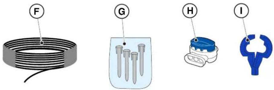
text_image
Diagram showing four labeled components: coiled wire, test tube, cap, and plastic connector with letter indicators.
3.3. UITPAKKEN
text_image
Safety warning signs and a robotic device with Chinese labels, including warning symbols for accidents, safety measures, and no-discrimination.

LET OP:
text_image
Diagram showing four symbols: battery pack, recycling symbol, no-renewable waste bin, and water-related warning sign.

LET OP:
Zie Hfdst. 9 "Toebehoren"
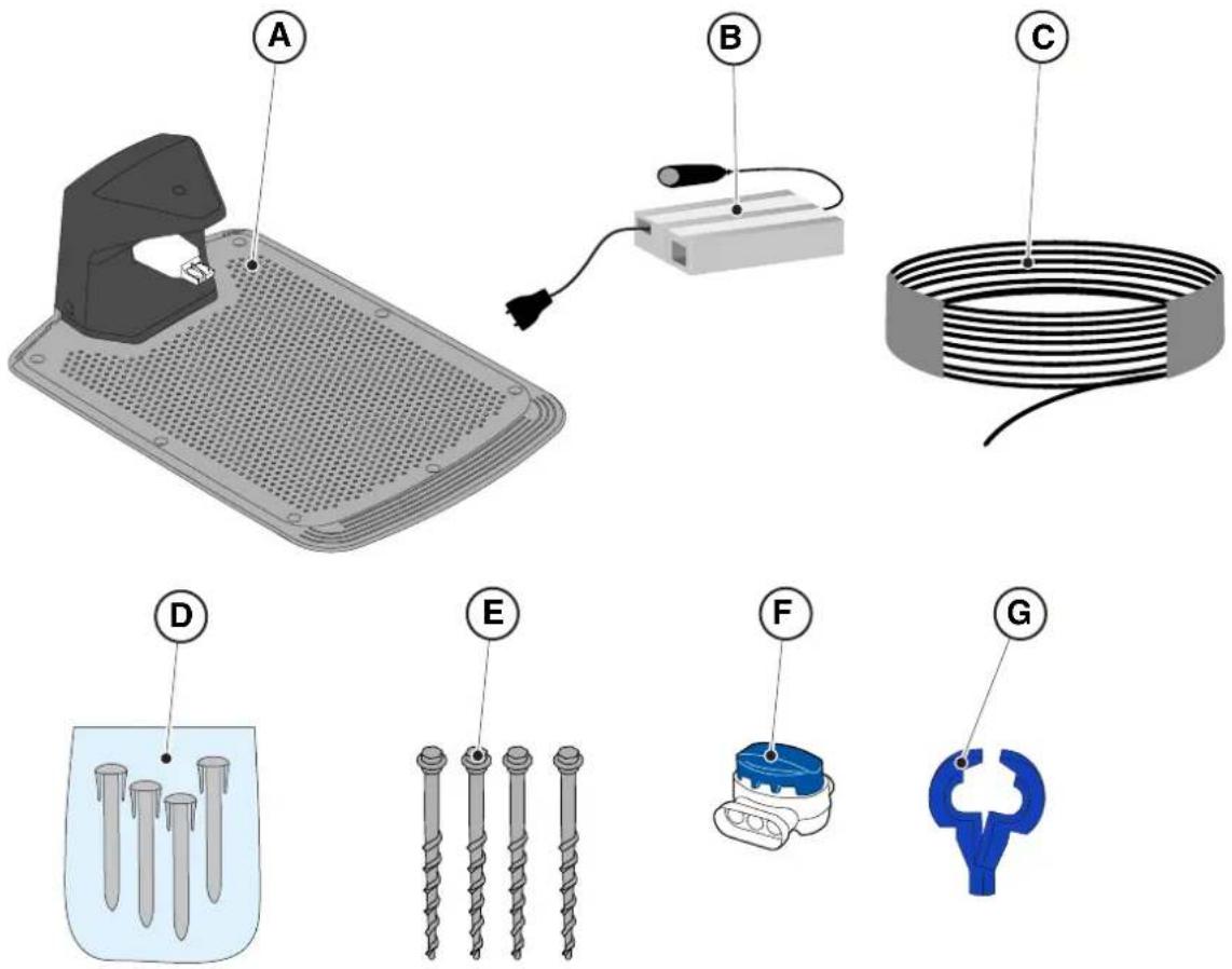
text_image
Diagram showing labeled components of a mechanical or electrical device, including iron iron, cable, and screw assembly parts.
4.3. CONTROLE VAN DE VEREISTEN VOOR DE INSTALLATIE
text_image
Diagram illustrating a device placement or positioning system with labeled points A, B, C and directional arrows marked x and x̄

LET OP:
text_image
Diagram showing a device mounted on a wall with a ruler and a mouse, labeled with dimension 'X' and figure marker (B)
4.3.3. BELANGRIJKSTE CONTROLES VOOR DE INSTALLATIE VAN DE PERIMETERDRAAD
text_image
E
≥ 35cm
d
> 45%
X

LET OP:
text_image
Diagram illustrating plant growth in a pond with labeled points G and F, showing green plants and water levels.
4.4. CRITERIA VOOR DE INSTALLATIE VAN DE GRENSKABEL
4.4.1. PLAATSING VAN DE PERIMETERDRAAD
Procedure:
text_image
F
D
X3
F
E
X3
STIGA
text_image
O
P
M
x6
O
P
N
x6

WAARSCHUWING:
natural_image
Illustration of a robotic device and tree trunk with labeled parts (Z and V), no text or symbols present.
4.4.3. PASSAGES TUSSEN VERSCHILLENDE DELEN VAN DE TUIN
Procedure:
PLAATSING MET HARINGEN
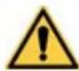
text_image
A
R=20 cm

text_image
B
100 cm
PLAATSING DOOR INGRAVEN
(ALLEEN UITVOERBAAR DOOR DE GEAUTORISEERDE VERKOPER)
text_image
Diagram illustrating the process of hairpin tool application, showing steps from pinning to cutting and holding a hairpin.
STIGA
text_image
Technical diagram of a mechanical assembly with labeled parts including screw, plate, and housing components

natural_image
3D diagram of a device with a green indicator light and a magnified view showing a component (no text or symbols)
natural_image
Diagram of a red electrical fuse or terminal block with a circular symbol indicating the pin (no text or labels present)

text_image
D2
C
O
I
E2E2
4.6. ROBOTMAAIER OPLADEN NA DE INSTALLATIE
| G 300 G 600 G | 1200 | |
| Border Cut |  |  |  |
| Go-To Cut Points | 1 3 5 | | |
| Eco Mode |  |  |  |
| Rain Sensor |  |  |  |
| Closed Area |  |  |  |
INDEX INSTELLINGEN VAN HET PRODUCT
4.7.1. PRELOGIN 31
4.7.2. REGISTRATIE (SIGN UP) 31
4.7.3. ASSOCIATIE (PAIRING) 31
4.7.4. PAGINA PRODUCT (DEVICE PAGE) 32
text_image
B
D
E
C
A
STOP
5.2. HANDMATIGE WERKING VAN DE ROBOTMAAIER
text_image
A C D B
STOP
L
E F G
text_image
A C D B
O H I L N
E F G M
5.3.1. VEILIG STOPPEN - STOP-KNOP
text_image
A C D B
STOP
E
5.3.4. SELECTIE GEPLAND PROGRAMMA / ENKELE WERKCYCLUS / GEDWONGEN TERUGKEER NAAR OPLAADBASIS - KNOP SELECTIE MODUS
TERUGKEER NAAR BASIS + GEPLAND PROGRAMMA
natural_image
Icon set with home, calendar, and checkmark symbols (no text or numbers)

natural_image
Icon set with home, calendar, and checkmark symbols (no text or numbers)

natural_image
Icon set with home, calendar, and checkmark symbols (no text or numbers)

natural_image
Icon set with home, calendar, and checkmark symbols on dark background (no text or numbers)

natural_image
Icon set with home, camera, and checklist symbols (no text or numbers)
STIGA
Procedure:
text_image
A C D B
STOP
I L
E F G
text_image
A C D B
STOP
M
5.3.6. WEERGAVE VAN DE ALARMSTATUSSEN - PICTOGRAM ALARM
text_image
A C D B
STOP
N
E
5.3.7. WEERGAVE VAN DE LAADSTATUS VAN DE ACCU - PICTOGRAM ACCU
natural_image
3D diagram of a device with a labeled component (N) and an inset showing a green button, no text or symbols present.
5.5. ACCU OPLADEN
Met de procedure "ACCU OPLADEN" kunt u de robotmaaier handmatig opladen.
text_image
A C B R S
O
E
5.6. AFSTELLING MAAIHOOGTE
natural_image
Diagram of green grasses with X and Y axis labels (no text or symbols on the grass itself)
Procedure:
natural_image
Diagram of a robotic vehicle showing internal components and a red arrow indicating motion (no text or symbols present)

text_image
Labeled diagram of a tank or vehicle showing internal components with numbered parts F, E, and G
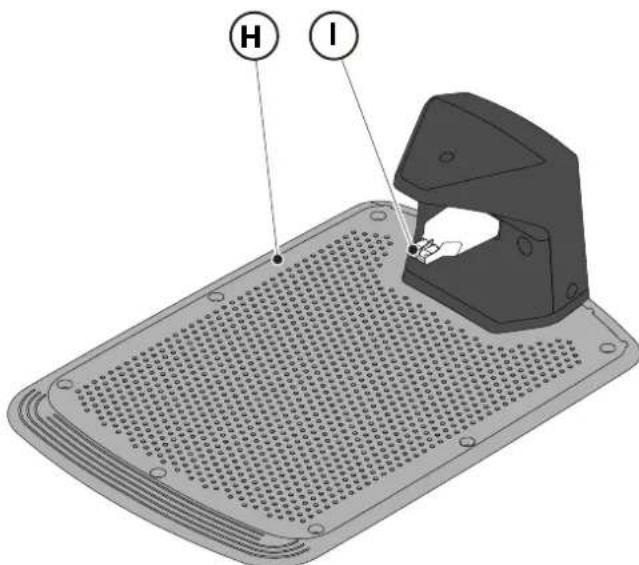
text_image
H
I
6.3. VERVANGING SNIJMESSEN

text_image
Technical diagram of a robotic vehicle showing internal components and labeled parts (D, E, D)
6.4. ONDERHOUD EN OPSLAG VAN DE ACCU IN DE WINTER
Procedure:
natural_image
3D rendering of a gray robotic device with a black handle and circular base (no text or symbols visible)
6.5. VERVANGING ACCU
(Supply of Machinery (Safety) Regulations 2008, S.I. 2008 No. 1597, Annex II, part A)
- The company: ST. S.p.A. – Via del Lavoro, 6 – 31033 Castelfranco Veneto (TV) – Italy
- Hereby declares under its own responsibility that the machine:
Robotic lawnmower
a) Homologation type: SRSW01
c) Serial number: 22A••RMO000001 ÷ 99L••RMO999999
d) Engine: battery-operated
- Conforms to UK Regulations:
• S.I. 2008/1597 - Supply of Machinery (Safety) Regulations 2008
• S.I. 2016/1091 - Electromagnetic Compatibility Regulations 2016
• S.I. 2012/3032 - The Restriction of the Use of Certain Hazardous Substances in Electrical and Electronic Equipment Regulations 2012
• S.I. 2017/1206 - Radio Equipment Regulations 2017
- Reference to harmonised standards:
EN 60335-1:2012 / AC:2014 / A11:2014 / A13:2017 / EN 61000-3-2:2019
A1:2019 / A2:2019 / A14:2019 EN 61000-3-3:2013 / A1:2019
EN IEC 63000:2018 EN 300 328 V2.2.2
EN 303 447 V1.2.0
EN 50636-107:2015 / A1 / A2
EN 301 489-17 V3.2.4
EN 62479:2010
EN 55014-1:2017 / A11:2020
EN 55014-2:2015
i) Cutting width: 18 cm
n) Person authorised to compile the technical file: ST. S.p.A.
Via del Lavoro, 6
31033 Castelfranco Veneto (TV) - Italia
o) Castelfranco Veneto, 01/12/2022 CEO Stiga Group
ST. S.p.A.
Via del Lavoro, 6
31033 Castelfranco Veneto (TV) - Italia
Sean Robinson

UK Importer:
STIGA LTD
Unit 8, Bluewater Estate Plympton,
Devon, PL7 4JH, England

| FR (Traduction de la notice originale)Déclaration CE de Conformité (Directive Machines 2006/42/CE, Annexe II, partie A)1. La Société2. Déclare sous sa propre responsabilité que la machine : Robot-tondeusea) Type / Modèle de Basec) Série d) Moteur: batterie3. Est conforme aux prescriptions des directives :4. Renvoi aux Normes harmoniséesi) Largeur de coupen) Personne habilitée à établir le Dossier Technique :o) Lieu et Date | DE (Übersetzung der Originalbetriebsanleitung)EG-Konformitätserklärung (Maschinenrichtlinie 2006/42/EG, Anhang II, Teil A)1. Die Gesellschaft2. Erklärt auf eigene Verantwortung, dass die Maschine: Mährobotera) Typ / Basismodellc) Seriennummerd) Motor: Batterie3. Den Anforderungen der folgenden Richtlinien entspricht:4. Bezugnahme auf die harmonisierten Normeni) Schnittbreiten) Zur Verfassung der technischen Unterlagen befugte Person:o) Ort und Datum | NL (Vertaling van de oorspronkelijke gebruiksaanwijzing)EG-verklaring van overeenstemming (Richtlijn Machines 2006/42/CE, Bijlage II, deel A)1. Het bedrijf2. Verklaart onder zijn eigen verantwoordelijkheid dat de machine: Robotmaaiera) Type / Basismodelc) Serienummerd) Motor: accu3. Voldoet aan de specificaties van der richtlijnen:4. Verwijzing naar de Geharmoniseerde normeni) Snijbreedten) Bevoegd persoon voor het opstellen van het Technisch Dossiero) Plaats en Datum |
| ES (Traducción del Manual Original)Declaración de Conformidad CE (Directiva Máquinas 2006/42/CE, Anexo II, parte A)1. La Empresa2. Declara bajo su propia responsabilidad que la máquina: Robot cortacéspeda) Tipo / Modelo Basec) Matrículad) Motor: bateria3. Cumple con las especificaciones de las directivas:4. Referencia a las Normas armonizadasi) Amplitud de corten) Persona autorizada a realizar el Manual Técnico:o) Lugar y Fecha | PT (Tradução do manual original)Declaração CE de Conformidade (Diretiva de Máquinas 2006/42/CE, Anexo II, parte A)1. A Empresa2. Declara sob a própria responsabilidade que a máquina: Robot corta-relvaa) Tipo / Modelo Basec) Matrículad) Moto: Bateria3. É conforme às especificações das diretivas:4. Referência às Normas harmonizadasi) Amplitude de corten) Pessoa autorizada a elaborar o Caderno Técnicoo) Local e Data | NO (Oversettelse av original bruksanvisning)EF- Samvarserklæring (Maskindirektiv 2006/42/EF, Vedlegg II, del A)1. Firmaet2. Erklærer på eget ansvar at maskinen: Robotgressklippera) Type / Modellc) Serienummerd) Motor: batteri3. Oppfyller kravene i direktivene:4. Henvisning til harmoniserte standarderI) Klippebredden) Person som har fullmakt til å ufterdige teknisk dokumentasjon:o) Sted og dato |
| SV (Översättning av bruksanvisning i original)EG-försäkran om överensstämmelse (Maskindirektiv 2006/42//EG, bilaga II, dela)1. Företaget2. Försäkrar på eget ansvar att maskinen: Gräsklipparrobota) Typ / Basmodellc) Serienummerd) Motor: batteri3. Överensstämmer med föreskrifterna i direktivet4. Referens till harmoniserade standarderi) Skärbreddn) Auktoriserad person för upprättandet av den tekniska dokumentationen:o) Ort och datum | DA (Översættelse af den originale brugsanvisning)EF-overensstemmelseserklæring (Maskindirektiv 2006/42/EF, bilag II, del A)1. Firmaet2. Erklærer på eget ansvar, at maskinen: Robotplænekllippera) Type / Modelc) Serienummerd) Motor: batteri3. Er i overensstemmelse med specifikationerne ifølge direktiverne:4. Henvisning til harmoniserede standarderi) Klippebredden) Person, der har bemyndigelse til at udarbejde det tekniske dossier:o) Sted og dato | FI (Alkuperäisten ohjeiden käännös)EY-VAATIMUSTENMUKAISUUSVAKUUTUS (Konedirektiivi 2006/42/EY, Liite II, osa A)1. Yritys2. Vakuuttaa omalla vastuullaan, että kone: Robottiruohonlelikkurla) Tyyppl / Perusmalllc) Sarjanumerod) Moottori : akku3. On yhdenmukainen seuraavien direktiivien asettamien vaatimusten kanssa:4. Viittaus harmonisoituihin standardeihini) Leikkuuleveysn) Teknisten asiakirjojen laatimiseenvaltuutettu henkilö:o) Paikka ja päivämäärä |
| SL (Prevod izvirnih navodil)ES izjava o skladnosti (Direktiva 2006/42/ES) , priloga II, del A)1. Družba2. pod lastno odgovornostjo izjavlja, da je stroj: Robotska kosilnicaa) Tip / osnovni modelc) Serijska številkad) Motor: baterija3. Skladen je z določili direktiv :4. Sklicevanje na usklajene predpisei) Obseg košnjen) Oseba, pooblaščena za sestavotehnične knjižice:o) Kraj In datum | LT (Originalių instrukciju vertimas)EB atitikties deklaracija (Mašinų direktyva 2006/42/CE, Priedas II, dalis A)1. Bendrovė2. Prisilma atsakomybę, kad jrenglnys: Žolės pjovimo robotasa) Tipas / Bazinis Modelisc) Serijos numerisd) Variklis: baterija3. Atitinka direktyvose pateiktas specifikacijas:4. Nuoroda i suderintas Normasi) Pjovimo plotisn) Autorizuotas asmuo sudaryti Techninę Dokumentaciją:o) Vieta ir Data | LV (Instrukciju tulkojums no originálvalodas)EK atbilstības deklarācija (Direktīva 2006/42/EK par mašinām, pleilkums II, daļa A)1. Uzpēnums2. Uzņemoties par to pilnu atbildību, pazino, ka mašina: Robotizēta pljaujmašinaa) Tips / Bāzes modelsc) Sērijas numursd) Motors: akumulators3. Atbilst šādu direktīvu prasībām:4. Atsauce uz harmonizētiem standartiemi) Pljaušanas platumsn) Pilnvarotais darbinieks, kas sagatavoja tehnisko dokumentāciju:o) Vieta un datums |
| CS (Překlad původního návodu k používání)ES – Prohlášení o shodě(Směrnice o Strojních zařízeních 2006/42/ES, Přiloha II, část A)1. Společnost2. Prohlášuje na vlastní odpovědnost, že stroj: Robotická sekačkaa) Typ / Základní modelc) Výrobní číslod) Motor: akumulátor3. Je ve shodě s nařízeními směrnic:4. Odkazy na Harmonizované normyi) Šířka řezánín) Osoba autorizovaná pro vytvoření Technického spisu:o) Misto a Datum | PL (Tłumaczenie instrukcji oryginalnej)Deklaracja zgodności WE(Dyrektywa maszynowa 2006/42/WE,Załącznik II, część A)1. Spółka2. Oświadczenie na własną odpowiedzialność, że maszyna: Kosiarka trawnikowaa) Typ / Model podstawowyc) Numer seryjnyd) Silnik: akumulator3. Spełnia podstawowe wymogi następujących Dyrektyw:4. Odniesienie do Norm zharmonizowanychi) Szerokość cięcia n) Osoba upoważniona do zredagowania Dokumentacji technicznej:o) Miejscowość i data | ET (Algupārase kasutusjuhendi tõlge)EÜ vastavusdeklaratsioon(Masinadirektiiv 2006/42/EÜ, Lisa II, osa A)1. Firma2. Kinnitab omal vastutusel, et masin:Robotniiduka) Tüüp / Põhimudel c) Matrikkeld) Mootor: aku3. Vastab direktiivide nõuetele:4. Viide ühtlustatud standarditelei) Lõikelaiusn) Tehnilise Lehe autoriseeritud koostaja:o) Koht ja Kuupäev |
| HU (Eredeti használati utasítás fordítása)EK-megfelelőségi nyilatkozata(2006/42/EK gépirányelv, ll. melléklet "A" rész)1. Alulírott Vállalat2. Felelősségének teljes tudatában kijelenti, hogy az alábbi gép: Robotfűnyíróa) Típus / Alaptipusc) Gyártási számd) Motor: akkumulátor3. Megfelel az alábbi irányelvekelőírásainak:4. Hivatkozás a harmonizált szabványokrai) Vágási szélességn) Műszaki Dosszié szerkesztésérefelhatalmazott személy:o) Helye és ideje | RU (Перевод оригинальных инструкций)Декларация соответствия нормам EC (Direktiva o машинном оборудовании 2006/42/EC, Приложение II, часть A)1. Предприятие2. Заявляет под собственную ответственность, что машина: Робот-газонокосилкаa) Тип / Базовая модельc) Паспортd) Двигатель: батарея сгорания3. Соответствует требованиям следующих директив:4. Ссылки на гармонизированные нормыi) Амплитуда кошенияn) Лицо, уполномоченное на подготовку технической документации:o) Место и дата | HR (Prijevod originalnih uputa)EK Izjava o sukladnosti(Direktiva 2006/42/EZ o strojevima, dodatak II, dio A)1. Tvrtka:2. pod vlastitom odgovornošću izjavljuje da je stroj: Robotska kosilicaa) Vrsta / Osnovni modelc) Matični brojd) Motor: baterija3. sukladan s temeljnim zahtjevima direktiva:4. Primijenjene su slijedeće harmonizirane norme:i) Širina rezanján) Osoba ovlaštena za pravljenje Tehničke datoteke:o) Mjesto i datum |
| SR (Prevod originalnih uputstval)EC deklaracija o usaglašenosti (Direktiva o mašinama 2006/42/EC, Prilog II, deo A)1. Preduzeće2. Daje izjavu pod vlastitom odgovornošćuda je mašina: Robot kosačicaa) Tip / Osnovni modelc) Serijski brojd) Motor: akumulator3. U skladu s osnovnim zahtevima direktiva:4. Pozivanje na usklađene normei) Širina košenjan) Osoba ovlašćena za sastavljanje tehničke brošureo) Mesto i datum | TR (Orijinal Talimatların Tercümesi)AT Uygunluk Beyanı (2006/42/CE Makine Direktifi, Ek II, bölüm A)1. Şirket2. Şahsi sorumluluğu altında aşağıdaki makinenin: Robot çim biçme makinesia) Tip / Standart modelc) Sicil numarasıd) Motor : batarya3. Aşağıdaki direktiflerin özelliklerine uygun olduğunu beyan etmektedir:4. Harmonize standartlara atifi) Kesim genişligiń) Teknik Dosyayı oluşturmaya yetkili kişi:o) Yer ve Tarih | RO (Traducerea manualului fabricantului)CE -Declaratie de Conformitate (Directiva Mašini 2006/42/CE, Anexa II, partea A)1. Societatea2. Declară pe propria răspundere că mașina: Robot mașină de tuns iarbaa) Tip / Model de bazăc) Număr de seried) Motor: baterie3. Este în conformitate cu specificațiile directivelor:4. Referință la Standardele armonizatei) Lătimea de täieren) Persoană autorizată să întocmeascăDosarul Tehnico) Locul și Data |
STIGA
STIGA LTD (UK Importer)
Unit 8, Bluewater Estate Plympton, Devon, PL7 4JH, England
STIGA S.p.A.
Via del lavoro, 6
31033 Castelfranco Veneto (TV)
Italy

FR
natural_image
Two yellow and gray TIGA robotic vacuum cleaner units (no visible text or symbols)
natural_image
Line drawing of a TiGA robotic vacuum cleaner (no text or symbols on the device itself)
natural_image
Technical line drawing of a tracked robotic vehicle showing internal components and mounting hardware (no text or symbols)
1.2. DATOS TÉCNICOS
text_image
Diagram illustrating a robotic device (A) and its corresponding layout with labeled components including camera, screen, and control panel.
3.2.2. COMPONENTES PRINCIPALES
natural_image
Technical diagram showing two components: a mechanical housing labeled D and a rectangular device labeled E connected by wires (no text or symbols beyond labels)
text_image
Diagram showing four labeled components: coiled wire, test tube, cap, and plastic connector with letter indicators.
3.3. DESEMBALAJE
flowchart
graph TD
    A["123"] --> B["Box"]
    B --> C["Box with lid"]
    C --> D["Shovel with lid"]
    D --> E["Robot with stopper"]
    E --> F["Robot with cover grid"]
3.4. SÍMBOLOS Y PLACAS
text_image
Safety warning signs and a robotic device with Chinese labels, including warning symbols for accidents, safety measures, and no-discrimination.
ATENCIÓN:
text_image
Diagram showing four symbols: battery pack, recycling symbol, no-renewable waste bin, and water-related warning sign.
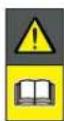
ATENCIÓN:
text_image
Diagram showing labeled components of a mechanical or electrical device, including an iron shaver, cable, and screw assembly.
text_image
Diagram showing a device placement on a wall with labeled points A, B, C and directional arrows indicating movement or positioning.

ATENCIÓN:
text_image
Diagram showing a device mounted on a wall with a ruler and a mouse, labeled with dimension 'X' and figure marker (B)
text_image
E
≥ 35cm
d
> 45%
X

ATENCIÓN:
text_image
Diagram illustrating plant growth in a pond with labeled points G and F, showing green plants and water levels.
text_image
F
D
x3
F
E
x3
STIGA
text_image
O
P
M
x6
O
P
N
x6

ADVERTENCIA:
natural_image
Illustration of a robotic device and tree trunk with labeled parts (Z and V), no text or symbols present.
4.4.3. PASOS ENTRE LAS DISTINTAS ZONAS DEL JARDÍN
Procedimiento:
text_image
Diagram illustrating the process of hairpin tool application, showing steps from cutting to holding a hairpin.
STIGA
text_image
Technical diagram of a mechanical assembly with labeled parts L, C, and M, showing screw installation and component layout.

natural_image
3D diagram of a mechanical device with a green indicator light and a magnified view showing internal components (no text or symbols)
natural_image
Diagram of a red electrical fuse or terminal block with a circular symbol indicating the pin (no text or labels present)

text_image
D2
C
O
I
E2E2
| G 300 G 600 G | 1200 | |
| Border Cut |  |  |  |
| Go-To Cut Points | 1 3 5 | | |
| Eco Mode |  |  |  |
| Rain Sensor |  |  |  |
| Closed Area | |  |  |
text_image
A
B
C
D
E
STOP
5.2. FUNCIONAMIENTO MANUAL DEL ROBOT CORTACÉSPED
text_image
A C D B
STOP
L
E F G
text_image
A C D B
STOP
O H I L N
E F G M
text_image
A C D B
STOP
E
natural_image
Icon set with home, calendar, and checkmark symbols (no text or numbers)

natural_image
Icon set with home, calendar, and checkmark symbols (no text or numbers)

natural_image
Icon set with home, calendar, and checkmark symbols (no text or numbers)

natural_image
Icon set with home, calendar, and checkmark symbols on dark background (no text or numbers)

natural_image
Icon set with home, camera, and checklist symbols (no text or numbers)
Procedimiento:
text_image
A C D B
STOP
I L
120
E F G
text_image
A C D B
STOP
M
text_image
A C D B
STOP
N
E
natural_image
3D diagram of a device with a mesh base and a magnified inset showing a green component labeled 'N' (no text or symbols on the main diagram)
5.5. CARGA DE LA BATERÍA
text_image
A C B R S
O
E
natural_image
Diagram of green grasses with X and Y axis labels (no text or symbols on the grass itself)
Procedimiento:
text_image
A C D B
STOP
P Q
6. MANTENIMIENTO
6.1. MANTENIMIENTO PROGRAMADO
natural_image
Diagram of a robotic vehicle showing internal components and a labeled point D (no text or symbols present)

ATENCIÓN:
text_image
Labeled diagram of a tracked vehicle showing key components: F, E, and G.
text_image
H
I
text_image
Technical diagram of a robotic vehicle showing internal components and labeled parts (D, E, D)
6.4. MANTENIMIENTO DE LA BATERÍA EN INVIERNO Y ALMACENAMIENTO
Procedimiento:
natural_image
3D rendering of a mechanical device with a circular base and handle (no text or symbols visible)
(Supply of Machinery (Safety) Regulations 2008, S.I. 2008 No. 1597, Annex II, part A)
- The company: ST. S.p.A. – Via del Lavoro, 6 – 31033 Castelfranco Veneto (TV) – Italy
- Hereby declares under its own responsibility that the machine:
Robotic lawnmower
a) Homologation type: SRSW01
c) Serial number: 22A••RMO000001 ÷ 99L••RMO999999
d) Engine: battery-operated
- Conforms to UK Regulations:
• S.I. 2008/1597 - Supply of Machinery (Safety) Regulations 2008
• S.I. 2016/1091 - Electromagnetic Compatibility Regulations 2016
• S.I. 2012/3032 - The Restriction of the Use of Certain Hazardous Substances in Electrical and Electronic Equipment Regulations 2012
• S.I. 2017/1206 - Radio Equipment Regulations 2017
- Reference to harmonised standards:
EN 60335-1:2012 / AC:2014 / A11:2014 / A13:2017 / EN 61000-3-2:2019
A1:2019 / A2:2019 / A14:2019 EN 61000-3-3:2013 / A1:2019
EN IEC 63000:2018 EN 300 328 V2.2.2
EN 303 447 V1.2.0
EN 50636-107:2015 / A1 / A2
EN 301 489-17 V3.2.4
EN 62479:2010
EN 55014-1:2017 / A11:2020
EN 55014-2:2015
i) Cutting width: 18 cm
n) Person authorised to compile the technical file: ST. S.p.A.
Via del Lavoro, 6
31033 Castelfranco Veneto (TV) - Italia
o) Castelfranco Veneto, 01/12/2022 CEO Stiga Group
ST. S.p.A.
Via del Lavoro, 6
31033 Castelfranco Veneto (TV) - Italia
Sean Robinson

UK Importer:
STIGA LTD
Unit 8, Bluewater Estate Plympton,
Devon, PL7 4JH, England

| FR (Traduction de la notice originale)Déclaration CE de Conformité (Directive Machines 2006/42/CE, Annexe II, partie A)1. La Société2. Déclare sous sa propre responsabilité que la machine : Robot-tondeusea) Type / Modèle de Basec) Série d) Moteur: batterie3. Est conforme aux prescriptions des directives :4. Renvoi aux Normes harmoniséesi) Largeur de coupen) Personne habilitée à établir le Dossier Technique :o) Lieu et Date | DE (Übersetzung der Originalbetriebsanleitung)EG-Konformitätserklärung (Maschinenrichtlinie 2006/42/EG, Anhang II, Teil A)1. Die Gesellschaft2. Erklärt auf eigene Verantwortung, dass die Maschine: Mährobotera) Typ / Basismodellc) Seriennummerd) Motor: Batterie3. Den Anforderungen der folgenden Richtlinien entspricht:4. Bezugnahme auf die harmonisierten Normeni) Schnittbreiten) Zur Verfassung der technischen Unterlagen befugte Person:o) Ort und Datum | NL (Vertaling van de oorspronkelijke gebruiksaanwijzing)EG-verklaring van overeenstemming (Richtlijn Machines 2006/42/CE, Bijlage II, deel A)1. Het bedrijf2. Verklaart onder zijn eigen verantwoordelijkheid dat de machine: Robotmaaiera) Type / Basismodelc) Serienummerd) Motor: accu3. Voldoet aan de specificaties van derichtlijnen:4. Verwijzing naar de Geharmoniseerde normeni) Snijbreedten) Bevoegd persoon voor het opstellen van het Technisch Dossiero) Plaats en Datum |
| ES (Traducción del Manual Original)Declaración de Conformidad CE (Directiva Máquinas 2006/42/CE, Anexo II, parte A)1. La Empresa2. Declara bajo su propia responsabilidad que la máquina: Robot cortacéspeda) Tipo / Modelo Basec) Matrículad) Motor: bateria3. Cumple con las especificaciones de las directivas:4. Referencia a las Normas armonizadasi) Amplitud de corten) Persona autorizada a realizar el Manual Técnico:o) Lugar y Fecha | PT (Tradução do manual original)Declaração CE de Conformidade (Diretiva de Máquinas 2006/42/CE, Anexo II, parte A)1. A Empresa2. Declara sob a própria responsabilidade que a máquina: Robot corta-relvaa) Tipo / Modelo Basec) Matrículad) Moto: Bateria3. É conforme às especificações das diretivas:4. Referência às Normas harmonizadasi) Amplitude de corten) Pessoa autorizada a elaborar o Caderno Técnicoo) Local e Data | NO (Oversettelse av original bruksanvisning)EF- Samvarserklæring (Maskindirektiv 2006/42/EF, Vedlegg II, del A)1. Firmaet2. Erklærer på eget ansvar at maskinen: Robotgressklippera) Type / Modellc) Serienummerd) Motor: batteri3. Oppfyller kravene i direktivene:4. Henvisning til harmoniserte standarderI) Klippebredden) Person som har fullmakt til å ufterdige teknisk dokumentasjon:o) Sted og dato |
| SV (Översättning av bruksanvisning i original)EG-försäkran om överensstämmelse (Maskindirektiv 2006/42//EG, bilaga II, dela)1. Företaget2. Försäkrar på eget ansvar att maskinen: Gräsklipparrobota) Typ / Basmodellc) Serienummerd) Motor: batteri3. Överensstämmer med föreskrifterna i direktivet4. Referens till harmoniserade standarderi) Skärbreddn) Auktoriserad person för upprättandet av den tekniska dokumentationen:o) Ort och datum | DA (Översættelse af den originale brugsanvisning)EF-overensstemmelseserklæring (Maskindirektiv 2006/42/EF, bilag II, del A)1. Firmaet2. Erklærer på eget ansvar, at maskinen: Robotplæneklippera) Type / Modelc) Serienummerd) Motor: batteri3. Er i overensstemmelse med specifikationerne ifølge direktiverne:4. Henvisning til harmoniserede standarderi) Klippebredden) Person, der har bemyndigelse til at udarbejde det tekniske dossier:o) Sted og dato | FI (Alkuperäisten ohjeiden käännös)EY-VAATIMUSTENMUKAISUUSVAKUUTUS (Konedirektiivi 2006/42/EY, Liite II, osa A)1. Yritys2. Vakuuttaa omalla vastuullaan, että kone: Robottiruohonlelikkurla) Tyyppl / Perusmalllc) Sarjanumerod) Moottori : akku3. On yhdenmukainen seuraavien direktiivien asettamien vaatimusten kanssa:4. Viittaus harmonisoituihin standardeihini) Leikkuuleveysn) Teknisten asiakirjojen laatimiseenvaltuutettu henkilö:o) Paikka ja päivämäärä |
| SL (Prevod izvirnih navodil)ES izjava o skladnosti (Direktiva 2006/42/ES) , priloga II, del A)1. Družba2. pod lastno odgovornostjo izjavlja, da je stroj: Robotska kosilnicaa) Tip / osnovni modelc) Serijska številkad) Motor: baterija3. Skladen je z določili direktiv :4. Sklicevanje na usklajene predpisei) Obseg košnjen) Oseba, pooblaščena za sestavotehnične knjižice:o) Kraj In datum | LT (Originalių instrukciju vertimas)EB atitikties deklaracija (Mašinų direktyva 2006/42/CE, Priedas II, dalis A)1. Bendrovė2. Prisilma atsakomybę, kad jrenglnys: Žolės pjovimo robotasa) Tipas / Bazinis Modelisc) Serijos numerisd) Variklis: baterija3. Atitinka direktyvose pateiktas specifikacijas:4. Nuoroda i suderintas Normasi) Pjovimo plotisn) Autorizuotas asmuo sudaryti Techninę Dokumentaciją:o) Vieta ir Data | LV (Instrukciju tulkojums no originálvalodas)EK atbilstības deklarācija (Direktīva 2006/42/EK par mašinām, pleilkums II, daļa A)1. Uzņēmums2. Uzņemoties par to pilnu atbildību, pazino, ka mašina: Robotizēta pljaujmašinaa) Tips / Bāzes modelsc) Sērijas numursd) Motors: akumulators3. Atbilst šādu direktīvu prasībām:4. Atsauce uz harmonizētiem standartiemi) Pljaušanas platumsn) Pilnvarotais darbinieks, kas sagatavoja tehnisko dokumentāciju:o) Vieta un datums |
d) Motor: akumulator
STIGA LTD (UK Importer)
Unit 8, Bluewater Estate Plympton, Devon, PL7 4JH, England
STIGA S.p.A.
Via del lavoro, 6
31033 Castelfranco Veneto (TV)
Italy

FR
natural_image
Two yellow and gray Stiga robotic vacuum cleaner units (no visible text or symbols)
PORTUGUÊS - TRADUÇÃO DAS INSTRUÇÕES ORIGINAIS
ÍNDICE
1. MODELOS E DADOS TÉCNICOS 1
1.1. MODELOS....1
1.2. DADOS TÉCNICOS....2
2. SEGURANÇA 3
2.1. INFORMAÇÕES RELATIVAS À SEGURANÇA ...... 3
2.2. INSTRUÇÕES DE SEGURANÇA......5
2.2.1. PRÁTICAS OPERACIONAIS SEGURAS....5
2.2.2. FUNCIONAMENTO....5
2.3. PARAGEM E DESLIGAMENTO DO ROBOT CORTA-RELVA EM CONDIÇÕES DE SEGURANÇA ..... 7
3. INTRODUÇÃO 8
3.1. INTRODUÇÃO GERAL 8
3.1.1. OBJETIVO DO MANUAL....8
3.1.2. INSTRUÇÕES PARA LEITURA ATRAVÉS DO SMARTPHONE....8
3.2. PANORÂMICA DO PRODUTO....9
3.2.1. DESCRIÇÃO GERAL 9
3.2.2. COMPONENTES PRINCIPAIS....10
3.3. DESEMBALAGEM....11
3.4. SÍMBOLOS E PLACAS 12
3.5. INSTRUÇÕES GERAIS DE LEITURA DO MANUAL....13
4. INSTALAÇÃO 14
natural_image
Line drawing of a robotic vacuum cleaner (no text or symbols)

natural_image
Technical line drawing of a tracked robotic vehicle showing internal components and mounting hardware (no text or symbols)
1.2. DADOS TÉCNICOS
natural_image
Technical diagram showing two components: a mechanical housing labeled D and a battery-like device labeled E, with no visible text or symbols.
text_image
Diagram showing four labeled components: coiled wire, cap with pins, mechanical component, and plastic head.
flowchart
graph TD
    A["123"] --> B["Box"]
    B --> C["Box with lid"]
    C --> D["Box with lid"]
    D --> E["Box with lid"]
    E --> F["Robot"]
    F --> G["Robot with lid"]
    G --> H["Robot with lid"]
3.4. SÍMBOLOS E PLACAS
text_image
Safety warning signs and robot diagram with Chinese labels for hazard, safety, vehicle, and pictograms
ATENÇÃO:
text_image
Diagram showing four symbols: battery pack, recycling symbol, no-renewable waste bin, and water-related warning sign.

ATENÇÃO:
text_image
Diagram showing labeled components of a mechanical or electrical device, including an iron shaver, cable, and screw assembly.
text_image
Diagram illustrating electrical grounding and safety monitoring setup with labeled components A, B, C and measurement indicators x, x̄

ATENÇÃO:
text_image
Diagram illustrating plant growth in a pond with labeled points G and F, showing green plants and water levels.
text_image
O
P
M
x6
O
P
N
x6

ADVERTÊNCIA:
flowchart
graph TD
    A["Central Structure"] --> B["Arrow to U"]
    B --> C["Star-like Elements"]
    C --> D["Arrow to Right"]
    D --> E["Arrow to Left"]
    E --> F["Arrow to Right"]
    F --> G["Arrow to Left"]
    G --> H["Arrow to Right"]
    H --> I["Arrow to Left"]
    I --> J["Arrow to Right"]
    J --> K["Arrow to Right"]
    K --> L["Arrow to Left"]
    L --> M["Arrow to Right"]
    M --> N["Arrow to Left"]
    N --> O["Arrow to Right"]
    O --> P["Arrow to Right"]
    P --> Q["Arrow to Left"]
    Q --> R["Arrow to Right"]
    R --> S["Arrow to Right"]
    S --> T["Arrow to Left"]
    T --> U["Arrow to Right"]
    U --> V["Arrow to Right"]
    V --> W["Arrow to Left"]
    W --> X["Arrow to Right"]
    X --> Y["Arrow to Right"]
natural_image
Illustration of a robotic device and tree trunk with labeled parts (Z and V), no text or symbols present.
4.4.3. PASSAGENS ENTRE DIVERSAS ZONAS DO JARDIM
Procedimento:
text_image
A
R=20 cm

text_image
B
100 cm
text_image
Diagram illustrating the process of hairpin tool application, showing steps from pinning to cutting and holding a hairpin.
STIGA
text_image
Technical diagram showing assembly of a mechanical component with labeled parts L, C, and M
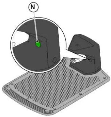
natural_image
3D diagram of a mechanical device with a green indicator light and a magnified view showing internal components (no text or symbols)
natural_image
Diagram of a red electrical fuse or terminal block with a circular symbol indicating the pin (no text or labels present)
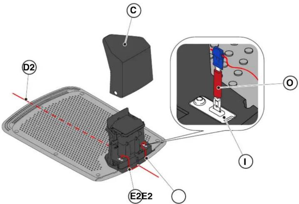
text_image
D2
C
O
I
E2E2
text_image
B
D
E
C
A
STOP
text_image
A C D B
STOP
L
E F G
text_image
A C D B
O H I L N
E F G M
5.3.1. PARAGEM EM SEGURANÇA - TECLA STOP
text_image
A C D B
STOP
E
natural_image
Icon set with home, calendar, and checkmark symbols (no text or numbers)

natural_image
Icon set with home, calendar, and checkmark symbols (no text or numbers)

natural_image
Icon set with home, calendar, and checkmark symbols (no text or numbers)

natural_image
Icon set with home, calendar, and checkmark symbols on dark background (no text or numbers)

natural_image
Icon set with home, camera, and checklist symbols (no text or numbers)
STIGA
Procedimento:
text_image
A C D B
STOP
I L
E F G
text_image
A C D B
STOP
M
text_image
A C D B
STOP
N
E
natural_image
3D diagram of a device with a labeled component (N) and an inset showing a green button, no text or symbols present.
text_image
A C B R S
O
E
natural_image
Diagram of green grasses with X and Y axis labels (no text or symbols on the grass itself)
Procedimento:
text_image
A C D B
STOP
P Q
6. MANUTENÇÃO
natural_image
Diagram of a robotic vehicle showing internal components and a labeled point D (no text or symbols present)

ATENÇÃO:
text_image
Labeled diagram of a tracked vehicle showing components F, E, and G with visible parts and motion indicators.

text_image
H
I
text_image
Technical diagram of a robotic vehicle showing labeled components and assembly view
natural_image
3D rendering of a gray robotic device with a black handle and control panel (no text or symbols visible)
(Supply of Machinery (Safety) Regulations 2008, S.I. 2008 No. 1597, Annex II, part A)
- The company: ST. S.p.A. – Via del Lavoro, 6 – 31033 Castelfranco Veneto (TV) – Italy
- Hereby declares under its own responsibility that the machine:
Robotic lawnmower
a) Homologation type: SRSW01
c) Serial number: 22A••RMO000001 ÷ 99L••RMO999999
d) Engine: battery-operated
- Conforms to UK Regulations:
• S.I. 2008/1597 - Supply of Machinery (Safety) Regulations 2008
• S.I. 2016/1091 - Electromagnetic Compatibility Regulations 2016
• S.I. 2012/3032 - The Restriction of the Use of Certain Hazardous Substances in Electrical and Electronic Equipment Regulations 2012
• S.I. 2017/1206 - Radio Equipment Regulations 2017
- Reference to harmonised standards:
EN 60335-1:2012 / AC:2014 / A11:2014 / A13:2017 / EN 61000-3-2:2019
A1:2019 / A2:2019 / A14:2019 EN 61000-3-3:2013 / A1:2019
EN IEC 63000:2018 EN 300 328 V2.2.2
EN 303 447 V1.2.0
EN 50636-107:2015 / A1 / A2
EN 301 489-17 V3.2.4
EN 62479:2010
EN 55014-1:2017 / A11:2020
EN 55014-2:2015
i) Cutting width: 18 cm
n) Person authorised to compile the technical file: ST. S.p.A.
Via del Lavoro, 6
31033 Castelfranco Veneto (TV) - Italia
o) Castelfranco Veneto, 01/12/2022 CEO Stiga Group
ST. S.p.A.
Via del Lavoro, 6
31033 Castelfranco Veneto (TV) - Italia
Sean Robinson

UK Importer:
STIGA LTD
Unit 8, Bluewater Estate Plympton,
Devon, PL7 4JH, England

| FR (Traduction de la notice originale)Déclaration CE de Conformité (Directive Machines 2006/42/CE, Annexe II, partie A)1. La Société2. Déclare sous sa propre responsabilité que la machine : Robot-tondeusea) Type / Modèle de Basec) Série d) Moteur: batterie3. Est conforme aux prescriptions des directives :4. Renvoi aux Normes harmoniséesi) Largeur de coupen) Personne habilitée à établir le Dossier Technique :o) Lieu et Date | DE (Übersetzung der Originalbetriebsanleitung)EG-Konformitätserklärung (Maschinenrichtlinie 2006/42/EG, Anhang II, Teil A)1. Die Gesellschaft2. Erklärt auf eigene Verantwortung, dass die Maschine: Mährobotera) Typ / Basismodellc) Seriennummerd) Motor: Batterie3. Den Anforderungen der folgenden Richtlinien entspricht:4. Bezugnahme auf die harmonisierten Normeni) Schnittbreiten) Zur Verfassung der technischen Unterlagen befugte Person:o) Ort und Datum | NL (Vertaling van de oorspronkelijke gebruiksaanwijzing)EG-verklaring van overeenstemming (Richtlijn Machines 2006/42/CE, Bijlage II, deel A)1. Het bedrijf2. Verklaart onder zijn eigen verantwoordelijkheid dat de machine: Robotmaaiera) Type / Basismodelc) Serienummerd) Motor: accu3. Voldoet aan de specificaties van der richtlijnen:4. Verwijzing naar de Geharmoniseerde normeni) Snijbreedten) Bevoegd persoon voor het opstellen van het Technisch Dossiero) Plaats en Datum |
| ES (Traducción del Manual Original)Declaración de Conformidad CE (Directiva Máquinas 2006/42/CE, Anexo II, parte A)1. La Empresa2. Declara bajo su propia responsabilidad que la máquina: Robot cortacéspeda) Tipo / Modelo Basec) Matrículad) Motor: bateria3. Cumple con las especificaciones de las directivas:4. Referencia a las Normas armonizadasi) Amplitud de corten) Persona autorizada a realizar el Manual Técnico:o) Lugar y Fecha | PT (Tradução do manual original)Declaração CE de Conformidade (Diretiva de Máquinas 2006/42/CE, Anexo II, parte A)1. A Empresa2. Declara sob a própria responsabilidade que a máquina: Robot corta-relvaa) Tipo / Modelo Basec) Matrículad) Moto: Bateria3. É conforme às especificações das diretivas:4. Referência às Normas harmonizadasi) Amplitude de corten) Pessoa autorizada a elaborar o Caderno Técnicoo) Local e Data | NO (Oversettelse av original bruksanvisning)EF- Samvarserklæring (Maskindirektiv 2006/42/EF, Vedlegg II, del A)1. Firmaet2. Erklærer på eget ansvar at maskinen: Robotgressklippera) Type / Modellc) Serienummerd) Motor: batteri3. Oppfyller kravene i direktivene:4. Henvisning til harmoniserte standarderI) Klippebredden) Person som har fullmakt til å ufterdige teknisk dokumentasjon:o) Sted og dato |
| SV (Översättning av bruksanvisning i original)EG-försäkran om överensstämmelse (Maskindirektiv 2006/42//EG, bilaga II, dela)1. Företaget2. Försäkrar på eget ansvar att maskinen: Gräsklipparrobota) Typ / Basmodellc) Serienummerd) Motor: batteri3. Överensstämmer med föreskrifterna i direktivet4. Referens till harmoniserade standarderi) Skärbreddn) Auktoriserad person för upprättandet av den tekniska dokumentationen:o) Ort och datum | DA (Översættelse af den originale brugsanvisning)EF-overensstemmelseserklæring (Maskindirektiv 2006/42/EF, bilag II, del A)1. Firmaet2. Erklærer på eget ansvar, at maskinen: Robotplæneklippera) Type / Modelc) Serienummerd) Motor: batteri3. Er i overensstemmelse med specifikationerne ifølge direktiverne:4. Henvisning til harmoniserede standarderi) Klippebredden) Person, der har bemyndigelse til at udarbejde det tekniske dossier:o) Sted og dato | FI (Alkuperäisten ohjeiden käännös)EY-VAATIMUSTENMUKAISUUSVAKUUTUS (Konedirektiivi 2006/42/EY, Liite II, osa A)1. Yritys2. Vakuuttaa omalla vastuullaan, että kone: Robottiruohonlelikkurla) Tyyppl / Perusmalllc) Sarjanumerod) Moottori : akku3. On yhdenmukainen seuraavien direktiivien asettamien vaatimusten kanssa:4. Viittaus harmonisoituihin standardeihini) Leikkuuleveysn) Teknisten asiakirjojen laatimiseenvaltuutettu henkilö:o) Paikka ja päivämäärä |
| SL (Prevod izvirnih navodil)ES izjava o skladnosti (Direktiva 2006/42/ES) , priloga II, del A)1. Družba2. pod lastno odgovornostjo izjavlja, da je stroj: Robotska kosilnicaa) Tip / osnovni modelc) Serijska številkad) Motor: baterija3. Skladen je z določili direktiv :4. Sklicevanje na usklajene predpisei) Obseg košnjen) Oseba, pooblaščena za sestavotehnične knjižice:o) Kraj In datum | LT (Originalių instrukciju vertimas)EB atitikties deklaracija (Mašinų direktyva 2006/42/CE, Priedas II, dalis A)1. Bendrovė2. Prisilma atsakomybę, kad jrenglnys: Žolės pjovimo robotasa) Tipas / Bazinis Modelisc) Serijos numerisd) Variklis: baterija3. Atitinka direktyvose pateiktas specifikacijas:4. Nuoroda i suderintas Normasi) Pjovimo plotisn) Autorizuotas asmuo sudaryti Techninę Dokumentaciją:o) Vieta ir Data | LV (Instrukciju tulkojums no originálvalodas)EK atbilstības deklarācija (Direktīva 2006/42/EK par mašinām, pleilkums II, daja A)1. Uzpēnums2. Uzņemoties par to pilnu atbildību, pazino, ka mašina: Robotizēta pljaujmašinaa) Tips / Bāzes modelsc) Sērijas numursd) Motors: akumulators3. Atbilst šādu direktīvu prasībām:4. Atsauce uz harmonizētiem standartiemi) Pljaušanas platumsn) Pilnvarotais darbinieks, kas sagatavoja tehnisko dokumentāciju:o) Vieta un datums |
| CS (Překlad původního návodu k používání)ES – Prohlášení o shodě(Směrnice o Strojních zařízeních 2006/42/ES, Přiloha II, část A)1. Společnost2. Prohlášuje na vlastní odpovědnost, že stroj: Robotická sekačkaa) Typ / Základní modelc) Výrobní číslod) Motor: akumulátor3. Je ve shodě s nařízeními směrnic:4. Odkazy na Harmonizované normyi) Šířka řezánín) Osoba autorizovaná pro vytvoření Technického spisu:o) Misto a Datum | PL (Tłumaczenie instrukcji oryginalnej)Deklaracja zgodności WE(Dyrektywa maszynowa 2006/42/WE,Załącznik II, część A)1. Spółka2. Oświadcza na własną odpowiedzialność, że maszyna: Kosiarka trawnikowaa) Typ / Model podstawowyc) Numer seryjnyd) Silnik: akumulator3. Spełnia podstawowe wymogi następujących Dyrektyw:4. Odniesienie do Norm zharmonizowanychi) Szerokość cięcia n) Osoba upoważniona do zredagowania Dokumentacji technicznej:o) Miejscowość i data | ET (Algupārase kasutusjuhendi tõlge)EÜ vastavusdeklaratsioon(Masinadirektiiv 2006/42/EÜ, Lisa II, osa A)1. Firma2. Kinnitab omal vastutusel, et masin:Robotniiduka) Tüüp / Põhimudel c) Matrikkeld) Mootor: aku3. Vastab direktiivide nõuetele:4. Viide ühtlustatud standarditelei) Lõikelaiusn) Tehnilise Lehe autoriseeritud koostaja:o) Koht ja Kuupäev |
| HU (Eredeti használati utasítás fordítása)EK-megfelelőségi nyilatkozata(2006/42/EK gépirányelv, ll. melléklet "A" rész)1. Alulírott Vállalat2. Felelősségének teljes tudatában kijelenti, hogy az alábbi gép: Robotfűnyíróa) Típus / Alaptipusc) Gyártási számd) Motor: akkumulátor3. Megfelel az alábbi irányelvekelőírásainak:4. Hivatkozás a harmonizált szabványokrai) Vágási szélességn) Műszaki Dosszié szerkesztésérefelhatalmazott személy:o) Helye és ideje | RU (Перевод оригинальных инструкций)Декларация соответствия нормам EC (Direktiva o машинном оборудовании 2006/42/EC, Приложение II, часть A)1. Предприятие2. Заявляет под собственную ответственность, что машина: Робот-газонокосилкаa) Тип / Базовая модельc) Паспортd) Двигатель: батарея сгорания3. Соответствует требованиям следующих директив:4. Ссылки на гармонизированные нормыi) Амплитуда кошенияn) Лицо, уполномоченное на подготовку технической документации:o) Место и дата | HR (Prijevod originalnih uputa)EK Izjava o sukladnosti(Direktiva 2006/42/EZ o strojevima, dodatak II, dio A)1. Tvrtka:2. pod vlastitom odgovornošću izjavljuje da je stroj: Robotska kosilicaa) Vrsta / Osnovni modelc) Matični brojd) Motor: baterija3. sukladan s temeljnim zahtjevima direktiva:4. Primijenjene su slijedeće harmonizirane norme:i) Širina rezanján) Osoba ovlaštena za pravljenje Tehničke datoteke:o) Mjesto i datum |
| SR (Prevod originalnih uputstval)EC deklaracija o usaglašenosti (Direktiva o mašinama 2006/42/EC, Prilog II, deo A)1. Preduzeće2. Daje izjavu pod vlastitom odgovornošćuda je mašina: Robot kosačicaa) Tip / Osnovni modelc) Serijski brojd) Motor: akumulator3. U skladu s osnovnim zahtevima direktiva:4. Pozivanje na usklađene normei) Širina košenjan) Osoba ovlašćena za sastavljanje tehničke brošureo) Mesto i datum | TR (Orijinal Talimatların Tercümesi)AT Uygunluk Beyanı (2006/42/CE Makine Direktifi, Ek II, bölüm A)1. Şirket2. Şahsi sorumluluğu altında aşağıdaki makinenin: Robot çim biçme makinesia) Tip / Standart modelc) Sicil numarasıd) Motor : batarya3. Aşağıdaki direktiflerin özelliklerine uygun olduğunu beyan etmektedir:4. Harmonize standartlara atifi) Kesim genişligiń) Teknik Dosyayı oluşturmaya yetkili kişi:o) Yer ve Tarih | RO (Traducerea manualului fabricantului)CE -Declaratie de Conformitate (Directiva Mašini 2006/42/CE, Anexa II, partea A)1. Societatea2. Declară pe propria răspundere că mașina: Robot mașină de tuns iarbaa) Tip / Model de bazăc) Număr de seried) Motor: baterie3. Este în conformitate cu specificațiile directivelor:4. Referință la Standardele armonizatei) Lătimea de täieren) Persoană autorizată să întocmeascăDosarul Tehnico) Locul și Data |
STIGA
STIGA LTD (UK Importer)
Unit 8, Bluewater Estate Plympton, Devon, PL7 4JH, England
STIGA S.p.A.
Via del lavoro, 6
31033 Castelfranco Veneto (TV)
Italy
stiga.com

FR
natural_image
Two yellow and gray Stiga robotic vacuum cleaner units (no visible text or symbols)
NORSK - OVERSETTELSE AV ORIGINALINSTRUKSJONER
INNHOLD
1. MODELLER OG TEKNISKE OPPLYSNINGER 1
1.1. MODELLER....1
1.2. TEKNISKE DATA....2
2. SIKKERHET 3
2.1. SIKKERHETSINFORMASJON....3
2.2. SIKKERHETSINSTRUKSJONER....5
2.2.1. SIKKER BRUKSPRAKSIS 5
2.2.2. DRIFT 5
2.3. STANS OG AVSKRUING AV ROBOTGRESSKLIPPEREN UNDER SIKRE FORHOLD 7
3. INTRODUKSJON 8
3.1. GENERELL INTRODUKSJON 8
3.1.1. FORMÅL MED HÅNDBOKEN....8
3.1.2. INSTRUKSJONER FOR LESNING AV INDIKASJONENE PÅ SMARTTELEFON 8
3.2. PRODUKTOVERSIKT....9
3.2.1. GENERELL BESKRIVELSE....9
3.2.2. HOVEDKOMPONENTER....10
3.3. UTPAKKING....11
3.4. SYMBOLER OG SKILT....12
3.5. GENERELLE INSTRUKSJONER FOR LESING AV HÅNDBOKEN 13
4. INSTALLASJON 14
4.1. GENERELL INSTALLASJONSINFORMASJON....14
4.2. KOMPONENTER FOR INSTALLASJONEN....14
4.3. KONTROLL AV INSTALLASJONSKRAV 15
4.3.1. KONTROLL AV HAGEN: 15
4.3.2. KONTROLLER INSTALLASJONEN AV LADEBASEN OG MATEREN: 15
4.3.3. HOVEDKONTROLLER FOR INSTALLASJON AV KANTLEDNINGEN: 17
4.4. KRITERIER FOR INSTALLASJON AV KANTLEDNINGEN....19
4.4.1. PLASSERING AV KANTLEDNINGEN 19
4.4.2. BEGRENSNING AV HINDRINGENE: 21
4.4.3. PASSASJE MELLOM ULIKE OMRÅDER I HAGEN 23
4.5. INSTALLASJON AV KOMPONENTENE 23
4.5.1. INSTALLASJON AV KANTLEDNINGEN....24
4.5.2. SKJ∅T VED KANTLEDNINGEN....25
4.5.3. INSTALLASJON AV LADEBASE 26
4.5.4. INSTALLASJON AV RESISTOR FOR REDUSERTE PARAMETERE....28
4.6. LADING AV ROBOTGRESSKLIPPER ETTER INSTALLASJON....29
4.7. PRODUKTINNSTILLINGER....30
5. DRIFT 35
5.1. KONTROLL AV SIKKERHETSENHETENE FOR OPPSTART AV ROBOTGRESSKLIPPEREN....35
5.2. MANUELL DRIFT AV ROBOTGRESSKLIPPEREN....36
5.3. BESKRIVELSE AV KOMMANDOENE SOM FINNES PÅ ROBOTGRESSKLIPPEREN 37
5.3.1. SIKKER STANS - STOPPKNAPP.... 37
5.3.2. SIKKER AVSKRUING - SIKKERHETSN∅KKEL.... 38
5.3.3. PÅSKRUING OG AVSKRUING - ON/OFF KNAPP 38
5.3.4. VALG AV PROGRAMMERT KLIPPING / ENKEL KLIPPESYKLUS - KNAPP PLANLAGT PROGRAM ..... 39
5.3.5. VISNING AV BLUETOOTH TILSTAND OG FRAKOBLING - BLUETOOTH KNAPP 41
5.3.6. VISNING AV ALARMTILSTAND - ALARMIKON....41
5.3.7. VISNING AV BATTERIETS LADING - BATTERI-IKON 42
5.3.8. OPPSTART AV ROBOTGRESSKLIPPEREN - STARTKNAPP 42
5.4. DRIFT AV LADEBASE....43
5.5. LADING AV BATTERI......43
5.6. JUSTERING AV KLIPPEH∅YDEN 44
6. VEDLIKEHOLD 45
6.1. PLANLAGT VEDLIKEHOLD....45
6.2. RENGJ∅RING AV PRODUKT 46
6.3. BYTTE AV KLIPPEINNRETNINGENE 48
6.4. VEDLIKEHOLD OM VINTEREN AV BATTERIET OG OPPBEVARING....49
6.5. UTSKIFTNING AV BATTERI 49
7. PROBLEML∅SNING 50
7.1. HOVEDMELDINGER FRA APPEN 51
8. TRANSPORT, OPPBEVARING OG KASSERING 53
8.1. TRANSPORT 53
8.2. OPPBEVARING 53
8.3. KASSERING......53
9. TILBEH∅R 54
- GARANTI 55
10.1. HVA SOM DEKKES AV GARANTIEN 55
- EU-SAMSVARSERKLÆRING 56
1. MODELLER OG TEKNISKE OPPLYSNINGER
1.1. MODELLER
Denne håndboken refererer til modellene G 300, G 600, G 1200.

natural_image
Line drawing of a robotic vacuum cleaner (no text or symbols)

natural_image
Technical line drawing of a tracked robotic vehicle showing internal components and mounting hardware (no text or symbols)
1.2. TEKNISKE DATA
| SPESIFIKASJONER | MÅLE ENHET | STIGA G 300 STIGA G 600 STIGA G 1200 |
| Dimensjoner (BxHxD) | [mm] 413 | x 252 x 560 413 x 252 x | 560 413 x 252 x 560 | |
| Robotgressklipperens vekt | [kg] 7.4 7 | 6 8 | | |
| Klippehøyde (Min-Maks) | [mm] 20-60 | 20-60 | 20-60 | |
| Bladdiameter | [mm] | 180 | 180 | 180 |
| Kuttehastighet | [omdr./min] | 2850+/-50 | 2850+/-50 | 2850+/-50 |
| Fremdriftshastighet | [m/min] | 22 | 22 | 22 |
| Maksimal helling | % | 45 | 45 | 45 |
| Maksimal helling langs omkretsen | % | 20 | 20 | 20 |
| Type elektrisk trekkmotor | - | Brushless | Brushless | Brushless |
| Type klippesystem | - | 4 svingbareklippeblader | 4 svingbareklippeblader | 4 svingbareklippeblader |
| Artikkelnummer for klippeinnretning | - | 322104105/0 | 322104105/0 | 322104105/0 |
| Type elektrisk klippemotor | - | Brushless | Brushless | Brushless |
| Påvist lydeffektnivå | [dB] (A) | 57 | 57 | 57 |
| Usikkerhet om støyutslipp, KWA | [dB] (A) | 1,47 | 1,47 | 1,47 |
| Garantert lydeffektnivå | [dB] (A) | 59 | 59 | 59 |
| Akustisk nivå ved operatørens øre | [dB] (A) | 46,3 | 46,3 | 46,3 |
| Robotgressklipper IP-klassifisering | - | IPX5 | IPX5 | IPX5 |
| IP-klassifisering av ladebasen | - | IPX1 | IPX1 | IPX1 |
| Mater IP-klassifisering | - | IP67 | IP67 | IP67 |
| Omgivelsestemperatur for robotgressklipper [°C] | [°C] | 0 ÷ 50 | 0 ÷ 50 | 0 ÷ 50 |
| Omgivelsestemperatur for ladebase [°C] | [°C] | -10 ÷ 50 | -10 ÷ 50 | -10 ÷ 50 |
| Omgivelsestemperatur for materdrift [°C] | [°C] | -10 ÷ 50 | -10 ÷ 50 | -10 ÷ 40 |
| Arbeidskapasitet | [m2] | 300 | 600 | 1200 |
| Strømforsyning | - | Input:100-240Vca; 1,2AOutput:30Vcc; 2A | Input:100-240Vca; 1,2AOutput:30Vcc; 2A | Input:100-240Vca; 1,2AOutput:30Vcc; 2A |
| Batterimodell | - | 25,2 - 25,9 V;2 Ah | 25,2 - 25,9 V;2,5 Ah | 25,2 - 25,9 V;5 Ah |
| Ladetid | [min] | 60 | 80 | 150 |
| Bluetooth | - | 4,2 4,2 | 4,2 | |
2. SIKKERHET
natural_image
Technical diagram showing two components: a mechanical housing labeled D and a rectangular device labeled E connected by wires (no text or symbols beyond labels)
text_image
Diagram showing four labeled components: coiled wire, test tube, mechanical component, and plastic clamp.
3.3. UTPAKKING
flowchart
graph TD
    A["123"] --> B["Box"]
    B --> C["Box with lid"]
    C --> D["Open Box with lid"]
    D --> E["Robot with 40kW"]
    E --> F["Robot with 5 on a perforated tray"]
3.4. SYMBOLER OG SKILT
Alle symbolene på robotgressklipperen er vist nedenfor:
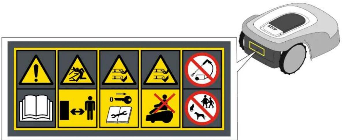
text_image
Safety warning signs and a robotic device with Chinese labels, including warning symbols for accidents, safety measures, and pictograms.
ADVARSEL:
text_image
Diagram showing four types of waste management symbols: recycling, no litter, fire, and water.

ADVARSEL:
text_image
Labeled diagram of electrical components including a power iron, cable, and various screw and nut parts with numbered labels.
4.3. KONTROLL AV INSTALLASJONSKRAV
text_image
Diagram illustrating a vehicle safety scenario with labeled points A, B, C and distance markers x and x', showing wiring connections and safety indicators.

ADVARSEL:
text_image
Diagram showing a device mounted on a wall with a ruler and a mouse, labeled with dimension 'X' and figure marker (B)
4.3.3. HOVEDKONTROLLER FOR INSTALLASJON AV KANTLEDNINGEN
text_image
E
≥ 35cm
d
> 45%
X
STIGA

ADVARSEL:
text_image
Diagram illustrating plant growth in a pond with labeled points G and F, showing green plants and water levels.
4.4. KRITERIER FOR INSTALLASJON AV KANTLEDNINGEN
4.4.1. PLASSERING AV KANTLEDNINGEN
Prosedyre:
text_image
F
D
X3
F
E
X3
STIGA
text_image
O
P
M
x6
O
P
N
x6

VARSEL:
flowchart
graph TD
    A["Central Rectangle"] --> B["Laptop"]
    B --> C["Light Grey Box"]
    C --> D["Square"]
    D --> E["Square"]
    E --> F["Circle"]
    F --> G["Circle"]
    G --> H["Circle"]
    H --> I["Circle"]
    I --> J["Circle"]
    J --> K["Circle"]
    K --> L["Circle"]
    L --> M["Circle"]
    M --> N["Circle"]
    N --> O["Circle"]
    O --> P["Circle"]
    P --> Q["Circle"]
    Q --> R["Circle"]
    R --> S["Circle"]
    S --> T["Circle"]
    T --> U["Circle"]
    U --> V["Circle"]
    V --> W["Circle"]
    W --> X["Circle"]
    X --> Y["Circle"]
    Y --> Z["Circle"]
natural_image
Illustration of a robotic vacuum cleaner and tree trunk with labeled parts (Z and V), no text or symbols present.
4.4.3. PASSASJE MELLOM TRE ULIKE OMRÅDER I HAGEN
Prosedyre:
text_image
A
R=20 cm

text_image
B
100 cm
PLASSERING VED Å GRAVE LEDNINGEN NED I BAKKEN
(SKAL KUN UTF∅RES AV GODKJENT FORHANDLER)
text_image
Diagram illustrating the process of hairpin tool application, showing steps from cutting to holding a hairpin.
STIGA
text_image
Technical diagram of a mechanical assembly with labeled parts L, C, and M, showing screw installation and component layout.

natural_image
3D diagram of a mechanical device with a green indicator light and a magnified view showing internal components (no text or symbols)
natural_image
Diagram of a red electrical fuse or terminal block with a circular symbol indicating the pin (no text or labels present)

text_image
D2
C
O
I
E2E2
4.6. LADING AV ROBOTGRESSKLIPPER ETTER INSTALLASJON
Krav og påbud:
- Ladebase.
Prosedyre:
| G 300 G 600 G | 1200 | |
| Border Cut | | | |
| Go-To Cut Points | 1 3 5 | | |
| Eco Mode | | | |
| Rain Sensor | |  |  |
| Closed Area | | | |
INDEKS FOR PRODUKTINNSTILLINGER
4.7.1. FORHÄNDSINNLOGGING 31
4.7.2. REGISTRERING (SIGN UP) 31
4.7.3. PARING (PAIRING) 31
4.7.4. PRODUKTSIDE (DEVICE PAGE) 32
4.7.5. LUKKET OMRÅDE (CLOSED AREA) 32
4.7.6. INNSTILLINGER (SETTINGS) 32
4.7.7. ENKEL KLIPPING / PLANLAGT KLIPPING (SPOT CUT / SCHEDULED).... 32
4.7.8. KLIPPE∅KTER (MOWING SESSIONS).... 32
4.7.9. GO-TO-CUT POINTS 33
4.7.10. KANTKLIPPING (BORDER CUT).... 33
4.7.11. ECO MODE....33
4.7.12. REGNSENSOR (RAIN SENSOR) (AVHENGIG AV MODELL) 33
4.7.13. TASTATURLÅS (APP LOCK) 33
4.7.14. BRUKERSTYRING 35
4.7.15. FORHANDLERE (DEALER) 35
4.7.16. MELDINGER (MESSAGES).... 35
4.7.17. PROFIL (PROFILE) 35
4.7.1. FORHÅNDSINNLOGGING
text_image
A
B
C
D
E
STOP
5.2. MANUELL DRIFT AV ROBOTGRESSKLIPPEREN
text_image
A C D B
STOP
L
E F G
text_image
A C D B
O H I L N
E F G M
5.3.1. SIKKER STANS - STOPPKNAPP
"STOP" knappen (A) er en kommando som stopper robotgressklipperen under trygge forhold, uansett driftstilstand.
Prosedyre:
text_image
A C D B
STOP
E
5.3.4. VALG AV PLANLAGT PROGRAM / ENKEL ARBEIDSSYKLUS / TVUNGEN RETUR TIL LADE-BASEN - KNAPP FOR MODUSVALG
natural_image
Icon set with home, calendar, and checkmark symbols (no text or numbers)
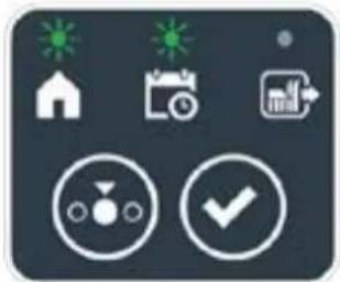
natural_image
Icon set with home, calendar, and checkmark symbols (no text or numbers)
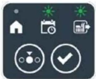
natural_image
Icon set with home, calendar, and checkmark symbols (no text or numbers)

natural_image
Icon set with home, calendar, and checkmark symbols on dark background (no text or numbers)

natural_image
Icon set with home, camera, and checklist symbols (no text or numbers)
STIGA
Prosedyre:
text_image
A C D B
3.0mm
STOP
I L
E F G
text_image
A C D B
STOP
M
5.3.6. VISNING AV ALARMTILSTAND - ALARMIKON
Det lysende "ALARM" ikonet (N) indikerer en driftsfeil.
Prosedyre:
text_image
A C D B
STOP
N
E
5.3.7. VISNING AV BATTERIETS LADING - BATTERI-IKON
Det lysende "BATTERI" ikonet (O) lar deg se batteriets ladestatus.
Prosedyre:
natural_image
3D diagram of a device with a mesh base and a magnified inset showing a green component labeled 'N' (no text or symbols on the main diagram)
5.5. LADING AV BATTERIET
text_image
A C B R S
O
E
5.6. REGULERING AV KLIPPEH∅YDEN
natural_image
Diagram of green grasses with X and Y axis labels (no text or symbols on the grass itself)
Prosedyre:
text_image
A C D B
STOP
P Q
6. VEDLIKEHOLD
6.1. PLANLAGT VEDLIKEHOLD
natural_image
Diagram of a robotic vehicle showing internal components and a labeled point D (no text or symbols present)

text_image
Labeled diagram of a tracked vehicle showing components F, E, and G with visible tire tracks and structural elements.
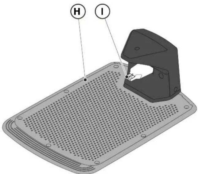
text_image
H
I
6.3. BYTTE AV KLIPPEINNRETNINGENE

VARSEL: Kuttefare for hendene.
Krav og påbud:
• Sikkerhetsnøkkel • Nøkkel
- Klippeblad • Hansker

text_image
Technical diagram of a robotic vehicle showing internal components and labeled parts (D, E, D)
6.4. VEDLIKEHOLD OM VINTEREN AV BATTERIET OG OPPBEVARING
Prosedyre:
natural_image
3D rendering of a robotic vacuum cleaner with a circular vent and handle (no text or symbols visible)
6.5. UTSKIFTNING AV BATTERI
(Supply of Machinery (Safety) Regulations 2008, S.I. 2008 No. 1597, Annex II, part A)
- The company: ST. S.p.A. – Via del Lavoro, 6 – 31033 Castelfranco Veneto (TV) – Italy
- Hereby declares under its own responsibility that the machine:
Robotic lawnmower
a) Homologation type: SRSW01
c) Serial number: 22A••RMO000001 ÷ 99L••RMO999999
d) Engine: battery-operated
- Conforms to UK Regulations:
• S.I. 2008/1597 - Supply of Machinery (Safety) Regulations 2008
• S.I. 2016/1091 - Electromagnetic Compatibility Regulations 2016
- S.I. 2012/3032 - The Restriction of the Use of Certain Hazardous Substances in Electrical and Electronic Equipment Regulations 2012
• S.I. 2017/1206 - Radio Equipment Regulations 2017
- Reference to harmonised standards:
EN 60335-1:2012 / AC:2014 / A11:2014 / A13:2017 / EN 61000-3-2:2019
A1:2019 / A2:2019 / A14:2019 EN 61000-3-3:2013 / A1:2019
EN IEC 63000:2018 EN 300 328 V2.2.2
EN 303 447 V1.2.0
EN 50636-107:2015 / A1 / A2
EN 301 489-17 V3.2.4
EN 62479:2010
EN 55014-1:2017 / A11:2020
EN 55014-2:2015
i) Cutting width: 18 cm
n) Person authorised to compile the technical file: ST. S.p.A.
Via del Lavoro, 6
31033 Castelfranco Veneto (TV) - Italia
o) Castelfranco Veneto, 01/12/2022 CEO Stiga Group
ST. S.p.A.
Via del Lavoro, 6
31033 Castelfranco Veneto (TV) - Italia
Sean Robinson

UK Importer:
STIGA LTD
Unit 8, Bluewater Estate Plympton,
Devon, PL7 4JH, England

| FR (Traduction de la notice originale)Déclaration CE de Conformité (Directive Machines 2006/42/CE, Annexe II, partie A)1. La Société2. Déclare sous sa propre responsabilité que la machine : Robot-tondeusea) Type / Modèle de Basec) Série d) Moteur: batterie3. Est conforme aux prescriptions des directives :4. Renvoi aux Normes harmoniséesi) Largeur de coupen) Personne habilitée à établir le Dossier Technique :o) Lieu et Date | DE (Übersetzung der Originalbetriebsanleitung)EG-Konformitätserklärung (Maschinenrichtlinie 2006/42/EG, Anhang II, Teil A)1. Die Gesellschaft2. Erklärt auf eigene Verantwortung, dass die Maschine: Mährobotera) Typ / Basismodellc) Seriennummerd) Motor: Batterie3. Den Anforderungen der folgenden Richtlinien entspricht:4. Bezugnahme auf die harmonisierten Normeni) Schnittbreiten) Zur Verfassung der technischen Unterlagen befugte Person:o) Ort und Datum | NL (Vertaling van de oorspronkelijke gebruiksaanwijzing)EG-verklaring van overeenstemming (Richtlijn Machines 2006/42/CE, Bijlage II, deel A)1. Het bedrijf2. Verklaart onder zijn eigen verantwoordelijkheid dat de machine: Robotmaaiera) Type / Basismodelc) Serienummerd) Motor: accu3. Voldoet aan de specificaties van der richtlijnen:4. Verwijzing naar de Geharmoniseerde normeni) Snijbreedten) Bevoegd persoon voor het opstellen van het Technisch Dossiero) Plaats en Datum |
| ES (Traducción del Manual Original)Declaración de Conformidad CE (Directiva Máquinas 2006/42/CE, Anexo II, parte A)1. La Empresa2. Declara bajo su propia responsabilidad que la máquina: Robot cortacéspeda) Tipo / Modelo Basec) Matrículad) Motor: bateria3. Cumple con las especificaciones de las directivas:4. Referencia a las Normas armonizadasi) Amplitud de corten) Persona autorizada a realizar el Manual Técnico:o) Lugar y Fecha | PT (Tradução do manual original)Declaração CE de Conformidade (Diretiva de Máquinas 2006/42/CE, Anexo II, parte A)1. A Empresa2. Declara sob a própria responsabilidade que a máquina: Robot corta-relvaa) Tipo / Modelo Basec) Matrículad) Moto: Bateria3. É conforme às especificações das diretivas:4. Referência às Normas harmonizadasi) Amplitude de corten) Pessoa autorizada a elaborar o Caderno Técnicoo) Local e Data | NO (Oversettelse av original bruksanvisning)EF- Samvarserklæring (Maskindirektiv 2006/42/EF, Vedlegg II, del A)1. Firmaet2. Erklærer på eget ansvar at maskinen: Robotgressklippera) Type / Modellc) Serienummerd) Motor: batteri3. Oppfyller kravene i direktivene:4. Henvisning til harmoniserte standarderI) Klippebredden) Person som har fullmakt til å ufterdige teknisk dokumentasjon:o) Sted og dato |
| SV (Översättning av bruksanvisning i original)EG-försäkran om överensstämmelse (Maskindirektiv 2006/42//EG, bilaga II, dela)1. Företaget2. Försäkrar på eget ansvar att maskinen: Gräsklipparrobota) Typ / Basmodellc) Serienummerd) Motor: batteri3. Överensstämmer med föreskrifterna i direktivet4. Referens till harmoniserade standarderi) Skärbreddn) Auktoriserad person för upprättandet av den tekniska dokumentationen:o) Ort och datum | DA (Översættelse af den originale brugsanvisning)EF-overensstemmelseserklæring (Maskindirektiv 2006/42/EF, bilag II, del A)1. Firmaet2. Erklærer på eget ansvar, at maskinen: Robotplæneklippera) Type / Modelc) Serienummerd) Motor: batteri3. Er i overensstemmelse med specifikationerne ifølge direktiverne:4. Henvisning til harmoniserede standarderi) Klippebredden) Person, der har bemyndigelse til at udarbejde det tekniske dossier:o) Sted og dato | FI (Alkuperäisten ohjeiden käännös)EY-VAATIMUSTENMUKAISUUSVAKUUTUS (Konedirektiivi 2006/42/EY, Liite II, osa A)1. Yritys2. Vakuuttaa omalla vastuullaan, että kone: Robottiruohonlelikkurla) Tyyppl / Perusmalllc) Sarjanumerod) Moottori : akku3. On yhdenmukainen seuraavien direktiivien asettamien vaatimusten kanssa:4. Viittaus harmonisoituihin standardeihini) Leikkuuleveysn) Teknisten asiakirjojen laatimiseenvaltuutettu henkilö:o) Paikka ja päivämäärä |
| SL (Prevod izvirnih navodil)ES izjava o skladnosti (Direktiva 2006/42/ES) , priloga II, del A)1. Družba2. pod lastno odgovornostjo izjavlja, da je stroj: Robotska kosilnicaa) Tip / osnovni modelc) Serijska številkad) Motor: baterija3. Skladen je z določili direktiv :4. Sklicevanje na usklajene predpisei) Obseg košnjen) Oseba, pooblaščena za sestavotehnične knjižice:o) Kraj In datum | LT (Originalių instrukciju vertimas)EB atitikties deklaracija (Mašinų direktyva 2006/42/CE, Priedas II, dalis A)1. Bendrovė2. Prisilma atsakomybę, kad jrenglnys: Žolės pjovimo robotasa) Tipas / Bazinis Modelisc) Serijos numerisd) Variklis: baterija3. Atitinka direktyvose pateiktas specifikacijas:4. Nuoroda i suderintas Normasi) Pjovimo plotisn) Autorizuotas asmuo sudaryti Techninę Dokumentaciją:o) Vieta ir Data | LV (Instrukciju tulkojums no originálvalodas)EK atbilstības deklarācija (Direktīva 2006/42/EK par mašinām, pleilkums II, daļa A)1. Uzņēmums2. Uzņemoties par to pilnu atbildību, pazino, ka mašina: Robotizēta pljaujmašinaa) Tips / Bāzes modelsc) Sērijas numursd) Motors: akumulators3. Atbilst šādu direktīvu prasībām:4. Atsauce uz harmonizētiem standartiemi) Plaušanas platumsn) Pilnvarotais darbinieks, kas sagatavoja tehnisko dokumentāciju:o) Vieta un datums |
| CS (Překlad původního návodu k používání)ES – Prohlášení o shodě(Směrnice o Strojních zařízeních 2006/42/ES, Přiloha II, část A)1. Společnost2. Prohlášuje na vlastní odpovědnost, že stroj: Robotická sekačkaa) Typ / Základní modelc) Výrobní číslod) Motor: akumulátor3. Je ve shodě s nařízeními směrnic:4. Odkazy na Harmonizované normyi) Šířka řezánín) Osoba autorizovaná pro vytvoření Technického spisu:o) Misto a Datum | PL (Tłumaczenie instrukcji oryginalnej)Deklaracja zgodności WE(Dyrektywa maszynowa 2006/42/WE,Załącznik II, część A)1. Spółka2. Oświadczenie na własną odpowiedzialność, że maszyna: Kosiarka trawnikowaa) Typ / Model podstawowyc) Numer seryjnyd) Silnik: akumulator3. Spełnia podstawowe wymogi następujących Dyrektyw:4. Odniesienie do Norm zharmonizowanychi) Szerokość cięcia n) Osoba upoważniona do zredagowania Dokumentacji technicznej:o) Miejscowość i data | ET (Algupārase kasutusjuhendi tõlge)EÜ vastavusdeklaratsioon(Masinadirektiiv 2006/42/EÜ, Lisa II, osa A)1. Firma2. Kinnitab omal vastutusel, et masin:Robotniiduka) Tüüp / Põhimudel c) Matrikkeld) Mootor: aku3. Vastab direktiivide nõuetele:4. Viide ühtlustatud standarditelei) Lõikelaiusn) Tehnilise Lehe autoriseeritud koostaja:o) Koht ja Kuupäev |
| HU (Eredeti használati utasítás fordítása)EK-megfelelőségi nyilatkozata(2006/42/EK gépirányelv, ll. melléklet "A" rész)1. Alulírott Vállalat2. Felelősségének teljes tudatában kijelenti, hogy az alábbi gép: Robotfűnyíróa) Típus / Alaptipusc) Gyártási számd) Motor: akkumulátor3. Megfelel az alábbi irányelvekelőírásainak:4. Hivatkozás a harmonizált szabványokrai) Vágási szélességn) Műszaki Dosszié szerkesztésérefelhatalmazott személy:o) Helye és ideje | RU (Перевод оригинальных инструкций)Декларация соответствия нормам EC (Direktiva o машинном оборудовании 2006/42/EC, Приложение II, часть A)1. Предприятие2. Заявляет под собственную ответственность, что машина: Робот-газонокосилкаa) Тип / Базовая модельc) Паспортd) Двигатель: батарея сгорания3. Соответствует требованиям следующих директив:4. Ссылки на гармонизированные нормыi) Амплитуда кошенияn) Лицо, уполномоченное на подготовку технической документации:o) Место и дата | HR (Prijevod originalnih uputa)EK Izjava o sukladnosti(Direktiva 2006/42/EZ o strojevima, dodatak II, dio A)1. Tvrtka:2. pod vlastitom odgovornošću izjavljuje da je stroj: Robotska kosilicaa) Vrsta / Osnovni modelc) Matični brojd) Motor: baterija3. sukladan s temeljnim zahtjevima direktiva:4. Primijenjene su slijedeće harmonizirane norme:i) Širina rezanján) Osoba ovlaštena za pravljenje Tehničke datoteke:o) Mjesto i datum |
| SR (Prevod originalnih uputstval)EC deklaracija o usaglašenosti (Direktiva o mašinama 2006/42/EC, Prilog II, deo A)1. Preduzeće2. Daje izjavu pod vlastitom odgovornošćuda je mašina: Robot kosačicaa) Tip / Osnovni modelc) Serijski brojd) Motor: akumulator3. U skladu s osnovnim zahtevima direktiva:4. Pozivanje na usklađene normei) Širina košenjan) Osoba ovlašćena za sastavljanje tehničke brošureo) Mesto i datum | TR (Orijinal Talimatların Tercümesi)AT Uygunluk Beyanı (2006/42/CE Makine Direktifi, Ek II, bölüm A)1. Şirket2. Şahsi sorumluluğu altında aşağıdaki makinenin: Robot çim biçme makinesia) Tip / Standart modelc) Sicil numarasıd) Motor : batarya3. Aşağıdaki direktiflerin özelliklerine uygun olduğunu beyan etmektedir:4. Harmonize standartlara atifi) Kesim genişligiń) Teknik Dosyayı oluşturmaya yetkili kişi:o) Yer ve Tarih | RO (Traducerea manualului fabricantului)CE -Declaratie de Conformitate (Directiva Mašini 2006/42/CE, Anexa II, partea A)1. Societatea2. Declară pe propria răspundere că mașina: Robot mașină de tuns iarbaa) Tip / Model de bazăc) Număr de seried) Motor: baterie3. Este în conformitate cu specificațiile directivelor:4. Referință la Standardele armonizatei) Lătimea de täieren) Persoană autorizată să întocmeascăDosarul Tehnico) Locul și Data |
STIGA
STIGA LTD (UK Importer)
Unit 8, Bluewater Estate Plympton, Devon, PL7 4JH, England
STIGA S.p.A.
Via del lavoro, 6
31033 Castelfranco Veneto (TV)
Italy
stiga.com

FR
natural_image
Two yellow and gray StiGA robotic vacuum cleaner units (no visible text or symbols)
SVENSKA - ÖVERSÄTTNING AV ORIGINALINSTRUKTIONERNA
INNEHÅLLSFÖRTECKNING
1. MODELLER OCH TEKNISKA SPECIFIKATIONER 1
1.1. MODELLER....1
1.2. TEKNISKA SPECIFICATIONER 2
2. SÄKERHET 3
2.1. SÄKERHETSINFORMATION....3
2.2. SÄKERHETSANVISNINGAR 5
2.2.1. SÄKRA DRIFTMETODER 5
2.2.2. FUNKTIONSSÄTT 5
2.3. STOPPA OCH STÄNGA AV ROBOTGRÄSKLIPPAREN PÅ ETT SÄKERT SÄTT....7
3. INTRODUKTION 8
3.1. ALLMÄN INTRODUKTION......8
3.1.1. HANDBOKENS SYFTE 8
3.1.2. INSTRUKTIONER FÖR LÄSNING FRÅN SMARTTELEFON8
3.2. PRODUKTÖVERSIKT 9
3.2.1. ALLMÄN BESKRIVNING 9
3.2.2. HUVUDKOMPONENTER....10
3.3. UPPACKNING 11
3.4. SYMBOLER OCH SKYLTAR 12
3.5. ALLMÄNNA INSTRUKTIONER FÖR ATT LÄSA HANDBOKEN....13
4. INSTALLATION 14
4.1. ALLMÄN INFORMATION FÖR INSTALLATIONEN....14
4.2. KOMPONENTER FÖR INSTALLATIONEN....14
4.3. KONTROLL AV INSTALLATIONSKRAVEN 15
4.3.1. KONTROLL AV TRÄDGÅRDEN: 15
4.3.2. KONTROLLER FÖR INSTALLATION AV LADDNINGSBASEN OCH MATAREN: 15
4.3.3. HUVUDKONTROLLER FÖR INSTALLATION AV BEGRÄNSNINGSKABEL: 17
4.4. KRITERIER FÖR INSTALLATION AV BEGRÄNSNINGSKABEL....19
4.4.1. PLACERING AV BEGRÄNSNINGSKABEL 19
4.4.2. AVGRÄNSNING AV HINDER: 21
4.4.3. VÄXLA MELLAN OLIKA DELAR AV TRÄDGÅRDEN.... 23
4.5. INSTALLATION AV KOMPONENTER....23
4.5.1. INSTALLATION AV AVGRÄNSNINGSKABELN....24
4.5.2. SAMMANFOGNING AV OMKRETSKABELN.... 25
4.5.3. INSTALLATION AV LADDNINGSBASEN 26
4.5.4. INSTALLATION AV MOTSTÅND FÖR SMA OMKRETSAR 28
4.6. LADDNING AV ROBOTGRÄSKLIPPAREN EFTER INSTALLATION29
4.7. PRODUKTINSTÄLLNINGAR 30
5. FUNKTIONSSÄTT 35
5.1. KONTROLL AV SÄKERHETSANORDNINGARNA FÖR ATT STARTA ROBOTGRÄSKLIPPAREN......35
5.2. MANUELL FUNKTION AV ROBOTGRÄSKLIPPAREN36
5.3. BESKRIVNING AV REGLAGEN SOM FINNS PÅ ROBOTGRÄSKLIPPAREN 37
5.3.1. STOPP I SÄKERHETSLÄGE - STOPPKNAPP 37
5.3.2. AVSTÄNGNING I SÄKERHETSLÄGE - SÄKERHETSNYCKEL 38
5.3.3. PÅSÄTTNING OCH AVSTÄNGNING - ON/OFF-KNAPP 38
5.3.4. VAL AV SCHEMALAGT PROGRAM/ENKEL ARBETSCYKEL - KNAPP .... SCHEMALAGT PROGRAM 39
5.3.5. BLUETOOTH STATUSDISPLAY OCH FRÄNKOPPLING - BLUETOOTH-KNAPP 41
5.3.6. VISNING AV LARMSTATUS - LARMIKON 41
5.3.7. VISNING AV BATTERILADDNINGEN - BATTERIIKON.... 42
5.3.8. START AV GRÄSKLIPPARROBOTEN - STARTKNAPP 42
5.4. ANVÄNDNING AV LADDNINGSBASEN 43
5.5. BATTERILADDNING 43
5.6. REGLERING AV KLIPPHÖJDEN 44
6. UNDERHÅLL 45
6.1. PLAERAT UNDERHÅLL 45
6.2. PRODUKTRENGÖRING 46
6.3. BYTE AV KLIPPBLAD 48
6.4. UNDERHÅLL OCH LAGRING AV BATTERIET FÖR VINTERN 49
6.5. BATTERIBYTE....49
7. FELSÖKNING 50
7.1. HUVUDMEDDELANDEN FRÅN APPEN 51
8. TRANSPORT, LAGRING OCH BORTSKAFFANDE 53
8.1. TRANSPORT....53
8.2. FÖRVARING 53
8.3. BORTSKAFFANDE....53
9. TILLBEHÖR 54
- GARANTI 55
10.1. GARANTINS TÄCKNING....55
- EG-FÖRSÄKRAN OM ÖVERENSSTÄMMELSE 56
1. MODELLER OCH TEKNISKA SPECIFIKATIONER
1.1. MODELLER
natural_image
Line drawing of a mounted robotic vacuum cleaner (no text or symbols)

natural_image
Technical line drawing of a tracked robotic vehicle showing internal components and mounting hardware (no text or symbols)
1.2. TEKNISKA SPECIFIKATIONER
natural_image
Technical diagram showing two components: a mechanical housing labeled D and a rectangular device labeled E connected by wires (no text or symbols beyond labels)
text_image
Diagram showing four labeled components: coiled wire, test tube, mechanical component, and plastic clamp.
3.3. UPPACKNING
flowchart
graph TD
    A["123"] --> B["Box"]
    B --> C["Box with lid"]
    C --> D["Shovel with lid"]
    D --> E["Robot with 4x60 sensor"]
    E --> F["Robot with 5x60 sensor"]
3.4. SYMBOLER OCH SKYLTAR
text_image
Safety warning signs and a robotic device with Chinese labels, including warning symbols for accidents, safety measures, and pictograms.

WARNING:
text_image
Diagram showing four types of environmental symbols: recycling, no litter, fire, and water discharge.

WARNING:
text_image
Labeled diagram of a medical or industrial device with components including a iron iron, cable, and screw assembly.
4.3. KONTROLL AV INSTALLATIONSKRAVEN
text_image
Diagram illustrating a vehicle safety scenario with labeled points A, B, C and distance markers x and x', showing wiring and safety indicators.

WARNING:
text_image
Diagram showing a device mounted on a wall with a labeled component and coordinate system (X)
4.3.3. HUVUDKONTROLLER FÖR INSTALLATION AV AVGRÄNSNINGSKABELN
text_image
Diagram illustrating a plant growing in a pond with labeled points G and F, showing green plants and rocks.
4.4. KRITERIER FÖR INSTALLATION AV OMKRETSKABELN
4.4.1. PLACERING AV AVGRÄNSNINGSKABELN
Förfarande:
text_image
F
D
x3
F
E
x3
STIGA
text_image
O
P
M
x6
O
P
N
x6

OBS:
flowchart
graph TD
    A["Central Rectangle"] --> B["Laptop"]
    B --> C["Light Grey Box"]
    C --> D["Square"]
    D --> E["Square"]
    E --> F["Circle"]
    F --> G["Circle"]
    G --> H["Circle"]
    H --> I["Circle"]
    I --> J["Circle"]
    J --> K["Circle"]
    K --> L["Circle"]
    L --> M["Circle"]
    M --> N["Circle"]
    N --> O["Circle"]
    O --> P["Circle"]
    P --> Q["Circle"]
    Q --> R["Circle"]
    R --> S["Circle"]
    S --> T["Circle"]
    T --> U["Circle"]
    U --> V["Circle"]
    V --> W["Circle"]
    W --> X["Circle"]
    X --> Y["Circle"]
    Y --> Z["Circle"]
natural_image
Illustration of a robotic device and tree trunk with labeled parts (Z and V), no text or symbols present.
4.4.3. VÄXLA MELLAN OLIKA DELAR AV TRÄDGÅRDEN
Förfarande:
text_image
A
R=20 cm

text_image
B
100 cm
POSITIONERING MED NEDGRÄVNING
(ENDAST TILLGÄNGLIG HOS AUKTORISERADE ÅTERFÖRSÄLJARE)
4.5.2. SAMMANFOGNING AV OMKRETSKABELN.

OBS:
text_image
Diagram illustrating the process of hairpin tool application, showing steps from pinning to cutting and holding a hairpin.
STIGA
text_image
Technical diagram of a mechanical assembly with labeled parts L, C, and M, showing components like screw holes and a housing.
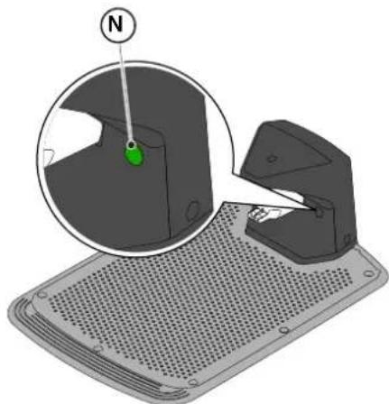
natural_image
3D diagram of a mechanical device with a magnified inset showing a green component labeled 'N' (no text or symbols on the main diagram)
natural_image
Diagram of a red electrical fuse with a labeled terminal (no text or symbols present)

text_image
D2
C
O
I
E2E2
4.6. LADDNING AV ROBOTGRÄSKLIPPAREN EFTER INSTALLATION
| G 300 G 600 G | 1200 | |
| Border Cut | | | |
| Go-To Cut Points | 1 3 5 | | |
| Eco Mode | | | |
| Rain Sensor | | | |
| Closed Area | | | |
PRODUKTINSTÄLLNINGSINDEX
4.7.1. FÖRE INLOGGNING....31
4.7.2. REGISTRERING (SIGN UP) 31
4.7.3. KOPPLING (PAIRING) 31
4.7.4. PRODUKTSIDA (DEVICE PAGE) 32
4.7.5. STÄNGT OMRÅDE (CLOSED AREA) 32
4.7.6. INSTÄLLNINGAR (SETTINGS) 32
4.7.7. ENKEL GRÄSKLIPPNING/SCHEMALAGD GRÄSKLIPPNING (SPOT CUT/SCHEDULED) 32
4.7.8. GRÄSKLIPPSSESSIONER (MOWING SESSIONS) 32
4.7.9. GO-TO-CUT POINTS 33
4.7.10. KANTKLIPPNING (BORDER CUT) 33
4.7.11. ECO MODE....33
4.7.12. REGNSENSOR (RAIN SENSOR) (BEROENDE PÅ MODELL) 33
4.7.13. BLOCKERING AV TANGENTBORD (APP LOCK) 33
4.7.14. ANVÄNDARHANTERING 35
4.7.15. ÅTERFÖRSÄLJARE (DEALER) 35
4.7.16. MEDDELANDEN (MESSAGES) 35
4.7.17. PROFIL (PROFILE) 35
4.7.1. INLEDNING
text_image
A
B
C
D
E
STOP
5.2. MANUELL ANVÄNDNING AV ROBOTGRÄSKLIPPAREN
text_image
A C D B
STOP
L
E F G
text_image
A C D B
STOP
O H I L N
E F G M
5.3.1. STOPP I SÄKERHETSLÄGE - STOPPKNAPP
natural_image
Icon set with home, calendar, and checkmark symbols (no text or numbers)

natural_image
Icon set with home, calendar, and checkmark symbols (no text or numbers)

natural_image
Icon set with home, calendar, and checkmark symbols on dark background (no text or numbers)

natural_image
Icon set with home, calendar, and checkmark symbols on dark background (no text or numbers)

natural_image
Icon set with home, camera, and checklist symbols (no text or numbers)
STIGA
Förfarande:
text_image
A C D B
30mm x 2.5mm
STOP
I L
E F G
text_image
A C D B
STOP
M
5.3.6. VISNING AV LARMSTATUS - LARMIKON
Lysikonen "LARM" (N) indikerar en avvikelse i funktionen.
Förfarande:
text_image
A C D B
STOP
N
E
5.3.7. VISNING AV BATTERILADDNINGEN - BATTERIIKON
text_image
A C D B
STOP
O
5.3.8. START AV ROBOTGRÄSKLIPPAREN
natural_image
3D diagram of a device with a mesh base and a magnified inset showing a green component labeled 'N' (no text or symbols on the main diagram)
5.5. BATTERILADDNING
text_image
A C B R S
O
E
5.6. REGLERING AV KLIPPHÖJDEN
natural_image
Diagram of green grasses with X and Y axis labels (no text or symbols on the grass itself)
Förfarande:
text_image
A C D B
STOP
P Q
6. UNDERHÅLL
natural_image
Diagram of a robotic vehicle with labeled parts (D) and internal components, no readable text or symbols present.
text_image
Labeled diagram of a tracked vehicle showing components F, E, and G with visible tire tracks and structural elements.

text_image
H
I
6.3. BYTE AV KLIPPNINGSBLAD

OBS:
text_image
Technical diagram of a robotic vehicle showing internal components and labeled parts (D, E, D)
6.4. UNDERHÅLL OCH LAGRING AV VINTERBATTERIET
Förfarande:
natural_image
3D rendering of a gray robotic device with a black handle and circular base (no text or symbols visible)
6.5. BATTERIBYTE
(Supply of Machinery (Safety) Regulations 2008, S.I. 2008 No. 1597, Annex II, part A)
-
The company: ST. S.p.A. – Via del Lavoro, 6 – 31033 Castelfranco Veneto (TV) – Italy
-
Hereby declares under its own responsibility that the machine:
Robotic lawnmower
a) Homologation type: SRSW01
c) Serial number: 22A••RMO000001 ÷ 99L••RMO999999
d) Engine: battery-operated
- Conforms to UK Regulations:
• S.I. 2008/1597 - Supply of Machinery (Safety) Regulations 2008
• S.I. 2016/1091 - Electromagnetic Compatibility Regulations 2016
• S.I. 2012/3032 - The Restriction of the Use of Certain Hazardous Substances in Electrical and Electronic Equipment Regulations 2012
• S.I. 2017/1206 - Radio Equipment Regulations 2017
- Reference to harmonised standards:
EN 60335-1:2012 / AC:2014 / A11:2014 / A13:2017 /
A1:2019 / A2:2019 / A14:2019
EN IEC 63000:2018
EN 61000-3-2:2019
EN 61000-3-3:2013 / A1:2019
EN 300 328 V2.2.2
EN 303 447 V1.2.0
EN 50636-107:2015/A1/A2
EN 301 489-17 V3.2.4
EN 62479:2010
EN 55014-1:2017 / A11:2020
EN 55014-2:2015
i) Cutting width: 18 cm
n) Person authorised to compile the technical file: ST. S.p.A.
Via del Lavoro, 6
31033 Castelfranco Veneto (TV) - Italia
o) Castelfranco Veneto, 01/12/2022 CEO Stiga Group
Sean Robinson

UK Importer:
STIGA LTD
Unit 8, Bluewater Estate Plympton,
Devon, PL7 4JH, England

| FR (Traduction de la notice originale)Déclaration CE de Conformité (Directive Machines 2006/42/CE, Annexe II, partie A)1. La Société2. Déclare sous sa propre responsabilité que la machine : Robot-tondeusea) Type / Modèle de Basec) Série d) Moteur: batterie3. Est conforme aux prescriptions des directives :4. Renvoi aux Normes harmoniséesi) Largeur de coupen) Personne habilitée à établir le Dossier Technique :o) Lieu et Date | DE (Übersetzung der Originalbetriebsanleitung)EG-Konformitätserklärung (Maschinenrichtlinie 2006/42/EG, Anhang II, Teil A)1. Die Gesellschaft2. Erklärt auf eigene Verantwortung, dass die Maschine: Mährobotera) Typ / Basismodellc) Seriennummerd) Motor: Batterie3. Den Anforderungen der folgenden Richtlinien entspricht:4. Bezugnahme auf die harmonisierten Normeni) Schnittbreiten) Zur Verfassung der technischen Unterlagen befugte Person:o) Ort und Datum | NL (Vertaling van de oorspronkelijke gebruiksaanwijzing)EG-verklaring van overeenstemming (Richtlijn Machines 2006/42/CE, Bijlage II, deel A)1. Het bedrijf2. Verklaart onder zijn eigen verantwoordelijkheid dat de machine: Robotmaaier a) Type / Basismodelc) Serienummerd) Motor: accu3. Voldoet aan de specificaties van der richtlijnen:4. Verwijzing naar de Geharmoniseerde normeni) Snijbreedten) Bevoegd persoon voor het opstellen van het Technisch Dossiero) Plaats en Datum |
| ES (Traducción del Manual Original)Declaración de Conformidad CE (Directiva Máquinas 2006/42/CE, Anexo II, parte A)1. La Empresa2. Declara bajo su propia responsabilidad que la máquina: Robot cortacéspeda) Tipo / Modelo Basec) Matrículad) Motor: bateria3. Cumple con las especificaciones de las directivas:4. Referencia a las Normas armonizadasi) Amplitud de corten) Persona autorizada a realizar el Manual Técnico:o) Lugar y Fecha | PT (Tradução do manual original)Declaração CE de Conformidade (Diretiva de Máquinas 2006/42/CE, Anexo II, parte A)1. A Empresa2. Declara sob a própria responsabilidade que a máquina: Robot corta-relva a) Tipo / Modelo Basec) Matrículad) Moto: Bateria3. É conforme às especificações das diretivas:4. Referência às Normas harmonizadasi) Amplitude de corten) Pessoa autorizada a elaborar o Caderno Técnicoo) Local e Data | NO (Oversettelse av original bruksanvisning)EF- Samvarserklæring (Maskindirektiv 2006/42/EF, Vedlegg II, del A)1. Firmaet2. Erklærer på eget ansvar at maskinen: Robotgressklippera) Type / Modellc) Serienummerd) Motor: batteri3. Oppfyller kravene i direktivene:4. Henvisning til harmoniserte standarderI) Klippebredden) Person som har fullmakt til å ufterdige teknisk dokumentasjon:o) Sted og dato |
| SV (Översättning av bruksanvisning i original)EG-försäkran om överensstämmelse (Maskindirektiv 2006/42//EG, bilaga II, dela)1. Företaget2. Försäkrar på eget ansvar att maskinen: Gräsklipparrobota) Typ / Basmodellc) Serienummerd) Motor: batteri3. Överensstämmer med föreskrifterna i direktivet4. Referens till harmoniserade standarderi) Skärbreddn) Auktoriserad person för upprättandet av den tekniska dokumentationen:o) Ort och datum | DA (Översættelse af den originale brugsanvisning)EF-overensstemmelseserklæring (Maskindirektiv 2006/42/EF, bilag II, del A)1. Firmaet2. Erklærer på eget ansvar, at maskinen: Robotplænekllippera) Type / Modelc) Serienummerd) Motor: batteri3. Er i overensstemmelse med specifikationerne ifølge direktiverne:4. Henvisning til harmoniserede standarderi) Klippebredden) Person, der har bemyndigelse til at udarbejde det tekniske dossier:o) Sted og dato | FI (Alkuperäisten ohjeiden käännös)EY-VAATIMUSTENMUKAISUUSVAKUUTUS (Konedirektiivi 2006/42/EY, Liite II, osa A)1. Yritys2. Vakuuttaa omalla vastuullaan, että kone: Robottiruohonlelikkurla) Tyyppl / Perusmalllc) Sarjanumerod) Moottori : akku3. On yhdenmukainen seuraavien direktiivien asettamien vaatimusten kanssa:4. Viittaus harmonisoituihin standardeihini) Leikkuuleveysn) Teknisten asiakirjojen laatimiseenvaltuutettu henkilö:o) Paikka ja päivämäärä |
| SL (Prevod izvirnih navodil)ES izjava o skladnosti (Direktiva 2006/42/ES) , priloga II, del A)1. Družba2. pod lastno odgovornostjo izjavlja, da je stroj: Robotska kosilnicaa) Tip / osnovni modelc) Serijska številkad) Motor: baterija3. Skladen je z določili direktiv :4. Sklicevanje na usklajene predpisei) Obseg košnjen) Oseba, pooblaščena za sestavotehnične knjižice:o) Kraj In datum | LT (Originalių instrukciju vertimas)EB atitikties deklaracija (Mašinų direktyva 2006/42/CE, Priedas II, dalis A)1. Bendrovė2. Prisilma atsakomybę, kad jrenglnys: Žolės pjovimo robotasa) Tipas / Bazinis Modelisc) Serijos numerisd) Variklis: baterija3. Atitinka direktyvose pateiktas specifikacijas:4. Nuoroda i suderintas Normasi) Pjovimo plotisn) Autorizuotas asmuo sudaryti Techninę Dokumentaciją:o) Vieta ir Data | LV (Instrukciju tulkojums no originálvalodas)EK atbilstības deklarācija (Direktīva 2006/42/EK par mašinām, pleilkums II, daļa A)1. Uzņēmums2. Uzņemoties par to pilnu atbildību, pazino, ka mašina: Robotizēta pljaujmašina a) Tips / Bāzes modelsc) Sērijas numursd) Motors: akumulators3. Atbilst šādu direktīvu prasībām:4. Atsauce uz harmonizētiem standartiemi) Pljaušanas platumsn) Pilnvarotais darbinieks, kas sagatavoja tehnisko dokumentāciju:o) Vieta un datums |
| CS (Překlad původního návodu k používání)ES – Prohlášení o shodě(Směrnice o Strojních zařízeních 2006/42/ES, Přiloha II, část A)1. Společnost2. Prohlášuje na vlastní odpovědnost, že stroj: Robotická sekačkaa) Typ / Základní modelc) Výrobní číslod) Motor: akumulátor3. Je ve shodě s nařízeními směrnic:4. Odkazy na Harmonizované normyi) Šířka řezánín) Osoba autorizovaná pro vytvoření Technického spisu:o) Misto a Datum | PL (Tłumaczenie instrukcji oryginalnej)Deklaracja zgodności WE(Dyrektywa maszynowa 2006/42/WE,Załącznik II, część A)1. Spółka2. Oświadczenie na własną odpowiedzialność, że maszyna: Kosiarka trawnikowaa) Typ / Model podstawowyc) Numer seryjnyd) Silnik: akumulator3. Spełnia podstawowe wymogi następujących Dyrektyw:4. Odniesienie do Norm zharmonizowanychi) Szerokość cięcia n) Osoba upoważniona do zredagowania Dokumentacji technicznej:o) Miejscowość i data | ET (Algupārase kasutusjuhendi tõlge)EÜ vastavusdeklaratsioon(Masinadirektiiv 2006/42/EÜ, Lisa II, osa A)1. Firma2. Kinnitab omal vastutusel, et masin:Robotniiduka) Tüüp / Põhimudel c) Matrikkeld) Mootor: aku3. Vastab direktiivide nõuetele:4. Viide ühtlustatud standarditelei) Lõikelaiusn) Tehnilise Lehe autoriseeritud koostaja:o) Koht ja Kuupäev |
| HU (Eredeti használati utasítás fordítása)EK-megfelelőségi nyilatkozata(2006/42/EK gépirányelv, ll. melléklet "A" rész)1. Alulírott Vállalat2. Felelősségének teljes tudatában kijelenti, hogy az alábbi gép: Robotfűnyíróa) Típus / Alaptipusc) Gyártási számd) Motor: akkumulátor3. Megfelel az alábbi irányelvekelőírásainak:4. Hivatkozás a harmonizált szabványokrai) Vágási szélességn) Műszaki Dosszié szerkesztésérefelhatalmazott személy:o) Helye és ideje | RU (Перевод оригинальных инструкций)Декларация соответствия нормам EC (Direktiva o машинном оборудовании 2006/42/EC, Приложение II, часть A)1. Предприятие2. Заявляет под собственную ответственность, что машина: Робот-газонокосилкаa) Тип / Базовая модельc) Паспортd) Двигатель: батарея сгорания3. Соответствует требованиям следующих директив:4. Ссылки на гармонизированные нормыi) Амплитуда кошенияn) Лицо, уполномоченное на подготовку технической документации:o) Место и дата | HR (Prijevod originalnih uputa)EK Izjava o sukladnosti (Direktiva 2006/42/EZ o strojevima, dodatak II, dio A)1. Tvrtka:2. pod vlastitom odgovornošću izjavljuje da je stroj: Robotska kosilicaa) Vrsta / Osnovni modelc) Matični brojd) Motor: baterija3. sukladan s temeljnim zahtjevima direktiva:4. Primijenjene su slijedeće harmonizirane norme:i) Širina rezanján) Osoba ovlaštena za pravljenje Tehničke datoteke:o) Mjesto i datum |
| SR (Prevod originalnih uputstval)EC deklaracija o usaglašenosti (Direktiva o mašinama 2006/42/EC, Prilog II, deo A)1. Preduzeće2. Daje izjavu pod vlastitom odgovornošćuda je mašina: Robot kosačicaa) Tip / Osnovni modelc) Serijski brojd) Motor: akumulator3. U skladu s osnovnim zahtevima direktiva:4. Pozivanje na usklađene normei) Širina košenjan) Osoba ovlašćena za sastavljanje tehničke brošureo) Mesto i datum | TR (Orijinal Talimatların Tercümesi)AT Uygunluk Beyanı (2006/42/CE Makine Direktifi, Ek II, bölüm A)1. Şirket2. Şahsi sorumluluğu altında aşağıdaki makinenin: Robot çim biçme makinesia) Tip / Standart modelc) Sicil numarasıd) Motor : batarya3. Aşağıdaki direktiflerin özelliklerine uygun olduğunu beyan etmektedir:4. Harmonize standartlara atifi) Kesim genişligiń) Teknik Dosyayı oluşturmaya yetkili kişi:o) Yer ve Tarih | RO (Traducerea manualului fabricantului)CE -Declaratie de Conformitate (Directiva Mašini 2006/42/CE, Anexa II, partea A)1. Societatea2. Declară pe propria răspundere că mașina: Robot mașină de tuns iarbaa) Tip / Model de bazăc) Număr de seried) Motor: baterie3. Este în conformitate cu specificațiile directivelor:4. Referință la Standardele armonizatei) Lătimea de täieren) Persoană autorizată să întocmeascăDosarul Tehnico) Locul și Data |
STIGA
STIGA LTD (UK Importer)
Unit 8, Bluewater Estate Plympton, Devon, PL7 4JH, England
STIGA S.p.A.
Via del lavoro, 6
31033 Castelfranco Veneto (TV)
Italy

FR
natural_image
Two yellow and gray Stiga robotic vacuum cleaner units (no visible text or symbols)
DANSK - OVERSÆTTELSE AF DEN ORIGINALE INSTRUKTIONSBOG
INDHOLDSFORTEGNELSE
1. MODELLER OG TEKNISKE OPLYSNINGER 1
1.1. MODELLER....1
1.2. TEKNISKE DATA....2
2. SIKKERHED 3
2.1. OPLYSNINGER OM SIKKERHED....3
2.2. SIKKERHEDSKONTROLLER 5
2.2.1. SIKRE DRIFTSMÆSSIGE FREMGANGSMÅDER 5
2.2.2. FUNKTION....5
2.3. STANDSNING OG SLUKNING AF ROBOTPLÆNEKLIPPERNE UNDER SIKRE FORHOLD ...... 7
3. INDLEDNING 8
3.1. GENEREL INDLEDNING 8
3.1.1. FORMÅLET MED BRUGERVEJLEDNINGEN ....8
3.1.2. INSTRUKTIONER TIL LÆSNING FRA SMARTPHONE 8
3.2. PRODUKTOVERSIGT 9
3.2.1. OVERORDNET BESKRIVELSE 9
3.2.2. HOVEDKOMPONENTER....10
3.3. UDPAKNING....11
3.4. SYMBOLER OG SKILTE 12
3.5. GENERELLE ANVISNINGER TIL LÆSNING AF INSTRUKTIONSBOGEN 13
4. INSTALLATION 14
4.1. GENERELLE OPLYSNINGER IFM. INSTALLATION .... 14
4.2. KOMPONENTER TIL INSTALLATIONEN 14
4.3. KONTROL AF FORUDSÆTNINGERNE TIL INSTALLATIONEN ....15
4.3.1. KONTROL AF HAVEN: 15
4.3.2. KONTROLLER AF LADESTATIONENS OG STRÖMFORSYNINGSENHEDENS INSTALLATION:...... 15
4.3.3. OVERORDNEDE KONTROLLER TIL INSTALLATION AF KANTLEDNINGEN: 17
4.4. KRITERIER TIL INSTALLATION AF KANTLEDNINGEN 19
4.4.1. PLACERING AF KANTLEDNINGEN.... 19
4.4.2. AFGRÆNSNING AF FORHINDRINGERNE: 21
4.4.3. GENNEMGANGE MELLEM HAVENS FORSKELLIGE OMRÅDER.... 23
4.5. INSTALLATION AF KOMPONENTERNE....23
4.5.1. INSTALLATION AF KANTLEDNING....24
4.5.2. KANTLEDNINGENS SAMLING.... 25
4.5.3. INSTALLATION AF LADESTATION 26
4.5.4. INSTALLATION AF MODSTAND TIL MINDRE OMRÅDER 28
4.6. GENOPLADNING AF ROBOTPLÄNEKLIPPEREN EFTER INSTALLATIONEN....29
4.7. PRODUKTETS INDSTILLINGER....30
5. FUNKTION
5.1. KONTROL AF SIKKERHEDSANORDNINGERNE TIL START AF ROBOTPLÆNEKLIPPEREN....35
5.2. MANUEL FUNKTION AF ROBOTPLÆNEKLIPPEREN 36
5.3. BESKRIVELSE AF BETJENINGSANORDNINGERNE PÅ ROBOTPLÆNEKLIPPEREN 37
5.3.1. SIKKERHEDSSTANDSNING - TRYKKNAP STOP 37
5.3.2. SIKKER SLUKNING - SIKKERHEDSN∅GLE 38
5.3.3. TÆNDING OG SLUKNING - TRYKKNAP ON/OFF 38
5.3.4. VALG AF PLANLAGT PROGRAM/ENKELT ARBEJDSCYKLUS - TRYKKNAP PLANLAGT PROGRAM ..... 39
5.3.5. VISNING AF BLUETOOTH-TILSTANDEN OG FRAKOBLING - TRYKKNAPPEN BLUETOOTH....41
5.3.6. VISNING AF ALARMTILSTANDENE - ALARMIKON 41
5.3.7. VISNING AF BATTERIOPLADNINGEN - BATTERIIKON 42
5.3.8. START AF ROBOTPLÆNEKLIPPEREN - TRYKKNAPPEN START 42
5.4. LADESTATIONENS FUNKTION 43
5.5. OPLADNING AF BATTERI 43
5.6. JUSTERING AF SKÆREH∅JDE 44
6. VEDLIGEHOLDELSE 45
6.1. PROGRAMMERET VEDLIGEHOLDELSE 45
6.2. RENG∅RING AF PRODUKT....46
6.3. UDSKIFTNING AF SKÆREKNIVE 48
6.4. VEDLIGEHOLDELSE AF BATTERIET F∅R VINTER OG OPLAGRING....49
6.5. UDSKIFTNING AF BATTERI....49
7. UDBEDRING AF PROBLEMERNE 50
7.1. HOVEDMEDDELELSER FRA APPEN....51
8. TRANSPORT, OPLAGRING OG BORTSKAFFELSE 53
8.1. TRANSPORT 53
8.2. OPLAGRING....53
8.3. BORTSKAFFELSE 53
9. TILBEH∅R 54
10. GARANTI 55
10.1. GARANTIDÆKNING....55
- EF-OVERENSSTEMMELSESERKLÆRING 56
1. MODELLER OG TEKNISKE OPLYSNINGER
1.1. MODELLER
Instruktionsbogen omhandler modellerne G 300, G 600, G 1200.

natural_image
Line drawing of a robotic vacuum cleaner (no text or symbols)

natural_image
Technical line drawing of a tracked robotic vehicle showing internal components and mounting hardware (no text or symbols)
1.2. TEKNISKE DATA
| TEKNISKE OPLYSNINGER | MÅLE ENHEDER | STIGA G 300 STIGA G 600 STIGA G 1200 |
| Dimensioner (BxHxD) | [mm] 413 x 252 x 560 413 x 252 x 560 413 x 252 x 560 | | | |
| Robotplæneklipperens vægt | [kg] 7,4 7,6 8 | | | |
| Klippehøjde (Min-Maks) | [mm] 20-60 20-60 | 20-60 | | |
| Knivens diameter | [mm] | 180 | 180 | 180 |
| Klippehastighed | [rpm] | 2850+/-50 | 2850+/-50 | 2850+/-50 |
| Kørehastighed | [m/min] | 22 | 22 | 22 |
| Maksimal hældning | % | 45 | 45 | 45 |
| Maksimal hældning langs omkredsen | % | 20 | 20 | 20 |
| Elektrisk drivmotortype | - | Brushless | Brushless | Brushless |
| Klippesystemets type | - | 4 drejelige skæreknive | 4 drejelige skæreknive | 4 drejelige skæreknive |
| Skæreanordningens kode | - | 322104105/0 | 322104105/0 | 322104105/0 |
| Elektrisk skæremotortype | - | Brushless | Brushless | Brushless |
| Registreret lydeffektniveau | [dB] (A) | 57 | 57 | 57 |
| Usikkerhed om støjemissionerne, KWA | [dB] (A) | 1,47 | 1,47 | 1,47 |
| Garanteret lydeffektniveau | [dB] (A) | 59 | 59 | 59 |
| Lydniveau ved operatørens øre | [dB] (A) | 46,3 | 46,3 | 46,3 |
| IP-klassificering robotplæneklipper | - | IPX5 | IPX5 | IPX5 |
| IP-klassificering opladningsstation | - | IPX1 | IPX1 | IPX1 |
| IP-klassificering strømforsyningsenhed | - | IP67 | IP67 | IP67 |
| Omgivelsestemperatur under robotplæneklipperens drift [°C] | [°C] | 0 ÷ 50 | 0 ÷ 50 | 0 ÷ 50 |
| Omgivelsestemperatur under opladningsstationens drift [°C] | [°C] | -10 ÷ 50 | -10 ÷ 50 | -10 ÷ 50 |
| Omgivelsestemperatur under strømforsyningsenhedens drift [°C] | [°C] | -10 ÷ 50 | -10 ÷ 50 | -10 ÷ 40 |
| Driftskapacitet | [m2] | 300 | 600 | 1200 |
| Strømforsyning | - | Indgang: 100-240Vca; 1,2A Output: 30Vcc; 2A | Indgang: 100-240Vca; 1,2A Output: 30Vcc; 2A | Indgang: 100-240Vca; 1,2A Output: 30Vcc; 2A |
| Batterimodel | - | 25,2 - 25,9 V; 2 Ah | 25,2 - 25,9 V; 2,5 Ah | 25,2 - 25,9 V; 5 Ah |
| Opladningstid | [min] | 60 | 80 | 150 |
| Bluetooth | - | 4,2 4,2 | 4,2 | |
2. SIKKERHED
2.1. OPLYSNINGER OM SIKKERHED
natural_image
Two electronic components: a mechanical housing labeled D and a battery-like device labeled E, with no visible text or symbols.
text_image
Diagram showing four labeled components: coiled wire, test tube, cap, and plastic connector with letter indicators.
3.3. UDPAKNING
flowchart
graph TD
    A["123"] --> B["Box"]
    B --> C["Box with lid"]
    C --> D["Box with lid"]
    D --> E["Robot with stop unit"]
    E --> F["Robot with filter unit"]
3.4. SYMBOLER OG SKILTE
text_image
Safety warning signs and a robotic device with Chinese labels, including warning symbols for accidents, safety measures, and no-discrimination.

ADVARSEL:
text_image
Diagram showing four symbols: battery pack, recycling symbol, no-renewable waste bin, and water-related warning sign.

ADVARSEL:
text_image
Diagram showing labeled components of a mechanical or electrical device, including a iron shaver, coiled cable, and various screw and nut parts.
4.3. KONTROL AF FORUDSÆTNINGERNE TIL INSTALLATIONEN
text_image
Diagram illustrating a vehicle safety scenario with labeled points A, B, C and distance markers x and x̄

ADVARSEL:
text_image
Diagram illustrating plant growth in a pond with labeled points G and F, showing green plants and water level.
4.4. KRITERIER TIL INSTALLATION AF KANTLEDNINGEN
4.4.1. PLACERING AF KANTLEDNINGEN
Fremgangsmåde:
text_image
O
P
M
x6
O
P
N
x6

FORSIGTIG:
flowchart
graph TD
    A["Central Structure"] --> B["Arrow to U"]
    B --> C["Star-like Elements"]
    C --> D["Arrow to Right"]
    D --> E["Arrow to Left"]
    E --> F["Arrow to Right"]
    F --> G["Arrow to Left"]
    G --> H["Arrow to Right"]
    H --> I["Arrow to Left"]
    I --> J["Arrow to Right"]
    J --> K["Arrow to Left"]
    K --> L["Arrow to Right"]
    L --> M["Arrow to Left"]
    M --> N["Arrow to Right"]
    N --> O["Arrow to Left"]
    O --> P["Arrow to Right"]
    P --> Q["Arrow to Left"]
    Q --> R["Arrow to Right"]
    R --> S["Arrow to Left"]
    S --> T["Arrow to Right"]
    T --> U["Arrow to Left"]
    U --> V["Arrow to Right"]
    V --> W["Arrow to Left"]
    W --> X["Arrow to Right"]
    X --> Y["Arrow to Left"]
    Y --> Z["Arrow to Right"]
natural_image
Illustration of a robotic device and tree trunk with labeled parts (Z and V), no text or symbols present.
4.4.3. GENNEMGANG MELLEM HAVENS FORSKELLIGE OMRÅDER
Fremgangsmåde:
PLACERING MED PL∅KKE

text_image
A
R=20 cm

text_image
B
100 cm
PLACERING UNDER JORDEN
(MÅ KUN UDF∅RES AF AUTORISERET FORHANDLER)
text_image
Diagram illustrating the process of hairpin tool application, showing steps from pinning to cutting and holding a hairpin.
STIGA
text_image
Technical diagram of a mechanical assembly with labeled parts L, C, and M, showing screw installation and component layout.

natural_image
3D diagram of a mechanical device with a green indicator light and a magnified view showing internal components (no text or symbols)
natural_image
Diagram of a red electrical fuse with a labeled terminal (no text or symbols present)

text_image
D2
C
O
I
E2E2
4.6. GENOPLADNING AF ROBOTPLÆNEKLIPPEREN EFTER INSTALLATIONEN
| G 300 G 600 G | 1200 | |
| Border Cut | | | |
| Go-To Cut Points | 1 3 5 | | |
| Eco Mode | | | |
| Rain Sensor | | | |
| Closed Area | | | |
OVERSIGT OVER PRODUKTETS INDSTILLINGER
4.7.1. PRELOGIN 31
4.7.2. REGISTRERING (SIGN UP) 31
4.7.3. TILKNYTNING (PAIRING) 31
4.7.4. PRODUKTSIDE (DEVICE PAGE) 32
4.7.5. LUKKET OMRÅDE (CLOSED AREA) 32
4.7.6. INDSTILLINGER (SETTINGS) 32
4.7.7. ENKELT KLIPNING/PROGRAMMERET TIDSPLAN (SPOT CUT/SCHEDULED).... 32
4.7.8. KLIPNINGSSESSIONER (MOWING SESSIONS) 32
4.7.9. GO-TO-CUT POINTS 33
4.7.10. KLIPNING AF KANT (BORDER CUT) 33
4.7.11. ECO MODE....33
4.7.12. REGNSENSOR (RAIN SENSOR) (AFHÆNGIGT AF MODELLEN) 33
4.7.13. TASTATURLÅS (APP LOCK) 33
4.7.14. BRUGERSTYRING....35
4.7.15. FORHANDLERE (DEALER) 35
4.7.16. MEDDELELSER (MESSAGES) 35
4.7.17. PROFIL (PROFILE) 35
4.7.1. F∅R LOGON
text_image
A
B
D
E
C
STOP
5.2. MANUEL FUNKTION AF ROBOTPLÄNEKLIPPEREN
text_image
A C D B
STOP
L
E F G
text_image
A C D B
STOP
O H I L N
E F G M
5.3.1. SIKKERHEDSSTANDSNING - TRYKKNAP STOP
Trykknappen "STOP" (A) er en betjeningsanordning, som standser robotplæneklipperen under sikre forhold, uanset dens driftsbetingelser.
Fremgangsmåde:
text_image
A C D B
STOP
E
5.3.4. VALG AF PLANLAGT PROGRAM/ENKELT ARBEJDSCYKLUS/TILBAGEK∅RSEL TIL LADE-STATIONEN - TRYKKNAP TIL VALG AF FUNKTION
natural_image
Icon set with home, calendar, and checkmark symbols (no text or numbers)

natural_image
Icon set with home, calendar, and checkmark symbols (no text or numbers)

natural_image
Icon set with home, calendar, and checkmark symbols (no text or numbers)
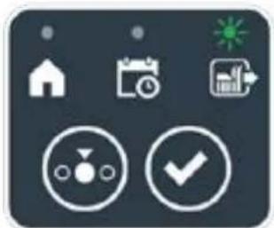
natural_image
Icon set with home, calendar, and checkmark symbols on dark background (no text or numbers)

natural_image
Icon set with home, camera, and checklist symbols (no text or numbers)
Fremgangsmåde:
text_image
A C D B
STOP
I L
E F G
text_image
A C D B
STOP
M
5.3.6. VISNING AF ALARMTILSTANDENE - ALARMIKON
Tændt ikon "ALARM" (N) angiver en anomali i driften.
Fremgangsmåde:
text_image
A C D B
STOP
N
E
5.3.7. VISNING AF BATTERIOPLADNINGEN - BATTERIIKON
natural_image
3D diagram of a device with a labeled component (N) and an inset showing a green indicator finger pointing to a component (no text or symbols on the main structure)
5.5. OPLADNING AF BATTERI
text_image
A C B R S
O
E
5.6. JUSTERING AF SKÆREH∅JDE
natural_image
Diagram of green grasses with X and Y axis labels (no text or symbols on the grass itself)
Fremgangsmåde:
text_image
A C D B
STOP
P Q
6. VEDLIGEHOLDELSE
6.1. PROGRAMMERET VEDLIGEHOLDELSE
6.2. RENG∅RING AF PRODUKT

natural_image
Diagram of a robotic vehicle showing internal components and a labeled point D (no text or symbols present)

text_image
Labeled diagram of a tracked vehicle showing components F, E, and G with visible parts and motion indicators.

text_image
H
I
6.3. UDSKIFTNING AF SKÆREKNIVE

text_image
Technical diagram of a robotic vehicle showing internal components and labeled parts (D, E, D)
6.4. VEDLIGEHOLDELSE AF BATTERIET F∅R VINTER OG OPLAGRING
Fremgangsmåde:
natural_image
3D rendering of a gray robotic device with a black handle and circular base (no text or symbols visible)
6.5. UDSKIFTNING AF BATTERI
(Supply of Machinery (Safety) Regulations 2008, S.I. 2008 No. 1597, Annex II, part A)
- The company: ST. S.p.A. – Via del Lavoro, 6 – 31033 Castelfranco Veneto (TV) – Italy
- Hereby declares under its own responsibility that the machine:
Robotic lawnmower
a) Homologation type: SRSW01
c) Serial number: 22A••RMO000001 ÷ 99L••RMO999999
d) Engine: battery-operated
- Conforms to UK Regulations:
• S.I. 2008/1597 - Supply of Machinery (Safety) Regulations 2008
• S.I. 2016/1091 - Electromagnetic Compatibility Regulations 2016
• S.I. 2012/3032 - The Restriction of the Use of Certain Hazardous Substances in Electrical and Electronic Equipment Regulations 2012
• S.I. 2017/1206 - Radio Equipment Regulations 2017
- Reference to harmonised standards:
EN 60335-1:2012 / AC:2014 / A11:2014 / A13:2017 / EN 61000-3-2:2019
A1:2019 / A2:2019 / A14:2019 EN 61000-3-3:2013 / A1:2019
EN IEC 63000:2018 EN 300 328 V2.2.2
EN 303 447 V1.2.0
EN 50636-107:2015 / A1 / A2
EN 301 489-17 V3.2.4
EN 62479:2010
EN 55014-1:2017 / A11:2020
EN 55014-2:2015
i) Cutting width: 18 cm
n) Person authorised to compile the technical file: ST. S.p.A.
Via del Lavoro, 6
31033 Castelfranco Veneto (TV) - Italia
o) Castelfranco Veneto, 01/12/2022 CEO Stiga Group
ST. S.p.A.
Via del Lavoro, 6
31033 Castelfranco Veneto (TV) - Italia
Sean Robinson

UK Importer:
STIGA LTD
Unit 8, Bluewater Estate Plympton,
Devon, PL7 4JH, England

| FR (Traduction de la notice originale)Déclaration CE de Conformité (Directive Machines 2006/42/CE, Annexe II, partie A)1. La Société2. Déclare sous sa propre responsabilité que la machine : Robot-tondeusea) Type / Modèle de Basec) Série d) Moteur: batterie3. Est conforme aux prescriptions des directives :4. Renvoi aux Normes harmoniséesi) Largeur de coupen) Personne habilitée à établir le Dossier Technique :o) Lieu et Date | DE (Übersetzung der Originalbetriebsanleitung)EG-Konformitätserklärung (Maschinenrichtlinie 2006/42/EG, Anhang II, Teil A)1. Die Gesellschaft2. Erklärt auf eigene Verantwortung, dass die Maschine: Mährobotera) Typ / Basismodellc) Seriennummerd) Motor: Batterie3. Den Anforderungen der folgenden Richtlinien entspricht:4. Bezugnahme auf die harmonisierten Normeni) Schnittbreiten) Zur Verfassung der technischen Unterlagen befugte Person:o) Ort und Datum | NL (Vertaling van de oorspronkelijke gebruiksaanwijzing)EG-verklaring van overeenstemming (Richtlijn Machines 2006/42/CE, Bijlage II, deel A)1. Het bedrijf2. Verklaart onder zijn eigen verantwoordelijkheid dat de machine: Robotmaaiera) Type / Basismodelc) Serienummerd) Motor: accu3. Voldoet aan de specificaties van derichtlijnen:4. Verwijzing naar de Geharmoniseerde normeni) Snijbreedten) Bevoegd persoon voor het opstellen van het Technisch Dossiero) Plaats en Datum |
| ES (Traducción del Manual Original)Declaración de Conformidad CE (Directiva Máquinas 2006/42/CE, Anexo II, parte A)1. La Empresa2. Declara bajo su propia responsabilidad que la máquina: Robot cortacéspeda) Tipo / Modelo Basec) Matrículad) Motor: bateria3. Cumple con las especificaciones de las directivas:4. Referencia a las Normas armonizadasi) Amplitud de corten) Persona autorizada a realizar el Manual Técnico:o) Lugar y Fecha | PT (Tradução do manual original)Declaração CE de Conformidade (Diretiva de Máquinas 2006/42/CE, Anexo II, parte A)1. A Empresa2. Declara sob a própria responsabilidade que a máquina: Robot corta-relvaa) Tipo / Modelo Basec) Matrículad) Moto: Bateria3. É conforme às especificações das diretivas:4. Referência às Normas harmonizadasi) Amplitude de corten) Pessoa autorizada a elaborar o Caderno Técnicoo) Local e Data | NO (Oversettelse av original bruksanvisning)EF- Samvarserklæring (Maskindirektiv 2006/42/EF, Vedlegg II, del A)1. Firmaet2. Erklærer på eget ansvar at maskinen: Robotgressklippera) Type / Modellc) Serienummerd) Motor: batteri3. Oppfyller kravene i direktivene:4. Henvisning til harmoniserte standarderI) Klippebredden) Person som har fullmakt til å ufterdige teknisk dokumentasjon:o) Sted og dato |
| SV (Översättning av bruksanvisning i original)EG-försäkran om överensstämmelse (Maskindirektiv 2006/42//EG, bilaga II, dela)1. Företaget2. Försäkrar på eget ansvar att maskinen: Gräsklipparrobota) Typ / Basmodellc) Serienummerd) Motor: batteri3. Överensstämmer med föreskrifterna i direktivet4. Referens till harmoniserade standarderi) Skärbreddn) Auktoriserad person för upprättandet av den tekniska dokumentationen:o) Ort och datum | DA (Översættelse af den originale brugsanvisning)EF-overensstemmelseserklæring (Maskindirektiv 2006/42/EF, bilag II, del A)1. Firmaet2. Erklærer på eget ansvar, at maskinen: Robotplænekllippera) Type / Modelc) Serienummerd) Motor: batteri3. Er i overensstemmelse med specifikationerne ifølge direktiverne:4. Henvisning til harmoniserede standarderi) Klippebredden) Person, der har bemyndigelse til at udarbejde det tekniske dossier:o) Sted og dato | FI (Alkuperäisten ohjeiden käännös)EY-VAATIMUSTENMUKAISUUSVAKUUTUS (Konedirektiivi 2006/42/EY, Liite II, osa A)1. Yritys2. Vakuuttaa omalla vastuullaan, että kone: Robottiruohonlelikkurla) Tyyppl / Perusmalllc) Sarjanumerod) Moottori : akku3. On yhdenmukainen seuraavien direktiivien asettamien vaatimusten kanssa:4. Viittaus harmonisoituihin standardeihini) Leikkuuleveysn) Teknisten asiakirjojen laatimiseenvaltuutettu henkilö:o) Paikka ja päivämäärä |
| SL (Prevod izvirnih navodil)ES izjava o skladnosti (Direktiva 2006/42/ES) , priloga II, del A)1. Družba2. pod lastno odgovornostjo izjavlja, da je stroj: Robotska kosilnicaa) Tip / osnovni modelc) Serijska številkad) Motor: baterija3. Skladen je z določili direktiv :4. Sklicevanje na usklajene predpisei) Obseg košnjen) Oseba, pooblaščena za sestavotehnične knjižice:o) Kraj In datum | LT (Originalių instrukciju vertimas)EB atitikties deklaracija (Mašinų direktyva 2006/42/CE, Priedas II, dalis A)1. Bendrovė2. Prisilma atsakomybę, kad jrenglnys: Žolės pjovimo robotasa) Tipas / Bazinis Modelisc) Serijos numerisd) Variklis: baterija3. Atitinka direktyvose pateiktas specifikacijas:4. Nuoroda i suderintas Normasi) Pjovimo plotisn) Autorizuotas asmuo sudaryti Techninę Dokumentaciją:o) Vieta ir Data | LV (Instrukciju tulkojums no originálvalodas)EK atbilstības deklarācija (Direktīva 2006/42/EK par mašinām, pleilkums II, daļa A)1. Uzņēmums2. Uzņemoties par to pilnu atbildību, pazino, ka mašina: Robotizēta pljaujmašinaa) Tips / Bāzes modelsc) Sērijas numursd) Motors: akumulators3. Atbilst šādu direktīvu prasībām:4. Atsauce uz harmonizētiem standartiemi) Pljaušanas platumsn) Pilnvarotais darbinieks, kas sagatavoja tehnisko dokumentāciju:o) Vieta un datums |
| CS (Překlad původního návodu k používání)ES – Prohlášení o shodě(Směrnice o Strojních zařízeních 2006/42/ES, Přiloha II, část A)1. Společnost2. Prohlášuje na vlastní odpovědnost, že stroj: Robotická sekačkaa) Typ / Základní modelc) Výrobní číslod) Motor: akumulátor3. Je ve shodě s nařízeními směrnic:4. Odkazy na Harmonizované normyi) Šířka řezánín) Osoba autorizovaná pro vytvoření Technického spisu:o) Misto a Datum | PL (Tłumaczenie instrukcji oryginalnej)Deklaracja zgodności WE(Dyrektywa maszynowa 2006/42/WE,Załącznik II, część A)1. Spółka2. Oświadcza na własną odpowiedzialność, że maszyna: Kosiarka trawnikowaa) Typ / Model podstawowyc) Numer seryjnyd) Silnik: akumulator3. Spełnia podstawowe wymogi następujących Dyrektyw:4. Odniesienie do Norm zharmonizowanychi) Szerokość cięcia n) Osoba upoważniona do zredagowania Dokumentacji technicznej:o) Miejscowość i data | ET (Algupārase kasutusjuhendi tõlge)EÜ vastavusdeklaratsioon(Masinadirektiiv 2006/42/EÜ, Lisa II, osa A)1. Firma2. Kinnitab omal vastutusel, et masin:Robotniiduka) Tüüp / Põhimudel c) Matrikkeld) Mootor: aku3. Vastab direktiivide nõuetele:4. Viide ühtlustatud standarditelei) Lõikelaiusn) Tehnilise Lehe autoriseeritud koostaja:o) Koht ja Kuupäev |
| HU (Eredeti használati utasítás fordítása)EK-megfelelőségi nyilatkozata(2006/42/EK gépirányelv, ll. melléklet "A" rész)1. Alulírott Vállalat2. Felelősségének teljes tudatában kijelenti, hogy az alábbi gép: Robotfűnyíróa) Típus / Alaptipusc) Gyártási számd) Motor: akkumulátor3. Megfelel az alábbi irányelvekelőírásainak:4. Hivatkozás a harmonizált szabványokrai) Vágási szélességn) Műszaki Dosszié szerkesztésérefelhatalmazott személy:o) Helye és ideje | RU (Перевод оригинальных инструкций)Декларация соответствия нормам EC (Direktiva o машинном оборудовании 2006/42/EC, Приложение II, часть A)1. Предприятие2. Заявляет под собственную ответственность, что машина: Робот-газонокосилкаa) Тип / Базовая модельc) Паспортd) Двигатель: батарея сгорания3. Соответствует требованиям следующих директив:4. Ссылки на гармонизированные нормыi) Амплитуда кошенияn) Лицо, уполномоченное на подготовку технической документации:o) Место и дата | HR (Prijevod originalnih uputa)EK Izjava o sukladnosti(Direktiva 2006/42/EZ o strojevima, dodatak II, dio A)1. Tvrtka:2. pod vlastitom odgovornošću izjavljuje da je stroj: Robotska kosilicaa) Vrsta / Osnovni modelc) Matični brojd) Motor: baterija3. sukladan s temeljnim zahtjevima direktiva:4. Primijenjene su slijedeće harmonizirane norme:i) Širina rezanján) Osoba ovlaštena za pravljenje Tehničke datoteke:o) Mjesto i datum |
| SR (Prevod originalnih uputstval)EC deklaracija o usaglašenosti (Direktiva o mašinama 2006/42/EC, Prilog II, deo A)1. Preduzeće2. Daje izjavu pod vlastitom odgovornošćuda je mašina: Robot kosačicaa) Tip / Osnovni modelc) Serijski brojd) Motor: akumulator3. U skladu s osnovnim zahtevima direktiva:4. Pozivanje na usklađene normei) Širina košenjan) Osoba ovlašćena za sastavljanje tehničke brošureo) Mesto i datum | TR (Orijinal Talimatların Tercümesi)AT Uygunluk Beyanı (2006/42/CE Makine Direktifi, Ek II, bölüm A)1. Şirket2. Şahsi sorumluluğu altında aşağıdaki makinenin: Robot çim biçme makinesia) Tip / Standart modelc) Sicil numarasıd) Motor : batarya3. Aşağıdaki direktiflerin özelliklerine uygun olduğunu beyan etmektedir:4. Harmonize standartlara atifi) Kesim genişligiń) Teknik Dosyayı oluşturmaya yetkili kişi:o) Yer ve Tarih | RO (Traducerea manualului fabricantului)CE -Declaratie de Conformitate (Directiva Mašini 2006/42/CE, Anexa II, partea A)1. Societatea2. Declară pe propria răspundere că mașina: Robot mașină de tuns iarbaa) Tip / Model de bazăc) Număr de seried) Motor: baterie3. Este în conformitate cu specificațiile directivelor:4. Referință la Standardele armonizatei) Lătimea de täieren) Persoană autorizată să întocmeascăDosarul Tehnico) Locul și Data |
STIGA
STIGA LTD (UK Importer)
Unit 8, Bluewater Estate Plympton, Devon, PL7 4JH, England
STIGA S.p.A.
Via del lavoro, 6
31033 Castelfranco Veneto (TV)
Italy

FR
natural_image
Two yellow and gray ATIGA robotic vacuum cleaner units (no visible text or symbols)
SUOMI - ALKUPERÄISTEN OHJEIDEN KÄÄNNÖS
SISÄLLYSLUETTELO
1. MALLIT JA TEKNISET TIEDOT 1
1.1. MALLIT....1
1.2. TEKNISET TIEDOT 2
2. TURVALLISUUS 3
2.1. TURVALLISUUTEEN LIITTYVÄÄ TIETOA....3
2.2. TURVAOHJEET 5
2.2.1. TURVALLISET TOIMINTATAVAT 5
2.2.2. TOIMINTA 5
2.3. ROBOTTIRUOHONLEIKKURIN PYSÄYTYS JA SAMMUTUS TURVAOLOSUHTEISSA 7
3. JOHDANTO 8
3.1. YLEINEN JOHDANTO 8
3.1.1. OHJEKIRJAN TARKOITUS 8
3.1.2. OHJEET LUENTAA VARTEN ÄLYPUHELIMESTA 8
3.2. TUOTTEEN YLEISKATSAUS 9
3.2.1. YLEINEN KUVAUS 9
3.2.2. PÄÄOSAT 10
3.3. PAKKAUKSESTA PURKAMINEN 11
3.4. SYMBOLIT JA KILVET 12
3.5. YLEISET OHJEET OHJEKIRJAN LUENTAAN....13
4. ASENNUS
4.1. ASENNUSTA KOSKEVAA YLEISTIETOA....14
4.2. KOMPONENTIT ASENNUSTA VARTEN....14
4.3. ASENNUKSEEN LIITTYVIEN VAATIMUSTEN TARKASTUS....15
4.3.1. PUUTARHAN TARKASTUS: 15
4.3.2. LATAUSASEMAN JA VIRTALÄHTEEN ASENNUS: 15
4.3.3. ENSISIJAISET TARKASTUKSET RAJAKAAPELIN ASENNUKSEEN: 17
4.4. RAJAKAAPELIN ASENNUSKRITEERIT....19
4.4.1. RAJAKAAPELIN ASEMOINTI....19
4.4.2. ESTEIDEN RAJAAMINEN: 21
4.4.3. REITIT PUUTARHAN ERI ALUEIDEN VÄLILLÄ....23
4.5. KOMPONENETTIEN ASENNUS....23
4.5.1. RAJAKAAPELIN ASEMOINTI....4
4.5.2. RAJAKAAPELIN LIITOS....25
4.5.3. LATAUSASEMAN ASENNUS....26
1. MALLIT JA TEKNISET TIEDOT
1.1. MALLIT
natural_image
Line drawing of a robotic vacuum cleaner (no text or symbols)

natural_image
Technical line drawing of a tracked robotic vehicle showing internal components and mounting hardware (no text or symbols)
1.2. TEKNISET TIEDOT
natural_image
Technical diagram showing two components: a mechanical housing labeled D and a rectangular device labeled E connected by wires (no text or symbols beyond labels)
text_image
Diagram showing four labeled components: coiled wire, plastic cup with pins, mechanical component, and plastic clamp.
3.3. PAKKAUKSEN PURKAMINEN
text_image
Safety warning signs and a robotic device with Chinese labels, including warning symbols for accidents, safety measures, and no-discrimination.

VAROITUS:
text_image
Diagram showing four symbols: battery pack, recycling symbol, no-renewable waste bin, and water-related warning sign.

VAROITUS:
text_image
Diagram showing labeled components of a medical or industrial device, including a iron grating, cable, and screw assembly.
4.3. ASENNUKSEEN LIITTYVIEN VAATIMUSTEN TARKASTUS
text_image
Diagram illustrating a room interior with labeled zones A, B, C and directional arrows indicating movement paths, including a monitor and a vehicle.

VAROITUS:
text_image
Diagram showing a device mounted on a wall with a ruler and a mouse, labeled with dimension 'X' and figure marker (B)
4.3.3. ENSISIJAISET TARKASTUKSET RAJAKAAPELIN ASENNUKSEEN
text_image
Diagram illustrating plant growth in a pond with labeled points G and F, showing green plants and water levels.
4.4. RAJAKAAPELIN ASENNUSKRITEERIT
4.4.1. RAJAKAAPELIN ASEMOINTI
Menettely:
text_image
F
D
X3
F
E
X3
STIGA
text_image
O
P
M
x6
O
P
N
x6

HUOMIO:
flowchart
graph TD
    A["Central Structure"] --> B["Arrow to U"]
    B --> C["Star-like Elements"]
    C --> D["Arrow to Right"]
    D --> E["Arrow to Left"]
    E --> F["Arrow to Right"]
    F --> G["Arrow to Left"]
    G --> H["Arrow to Right"]
    H --> I["Arrow to Left"]
    I --> J["Arrow to Right"]
    J --> K["Arrow to Left"]
    K --> L["Arrow to Right"]
    L --> M["Arrow to Left"]
    M --> N["Arrow to Right"]
    N --> O["Arrow to Left"]
    O --> P["Arrow to Right"]
    P --> Q["Arrow to Left"]
    Q --> R["Arrow to Right"]
    R --> S["Arrow to Left"]
    S --> T["Arrow to Right"]
    T --> U["Arrow to Left"]
    U --> V["Arrow to Right"]
    V --> W["Arrow to Left"]
    W --> X["Arrow to Right"]
    X --> Y["Arrow to Left"]
    Y --> Z["Arrow to Right"]
natural_image
Illustration of a robotic device and tree trunk with labeled parts (Z and V), no text or symbols present.
4.4.3. REITIT PUUTARHAN ERI ALUEIDEN VÄLILLÄ
Menettely:
text_image
A
R=20 cm

text_image
B
100 cm
ASEMOINTI UPOTTAMALLA
(SUORITETTAVA VAIN VALTUUTETUN JÄLLEENMYYJÄN TOIMESTA)
text_image
Diagram illustrating the process of hairpin tool application, showing steps from pinning to cutting and holding a hairpin.
STIGA
text_image
Technical diagram of a mechanical assembly with labeled parts L, C, and M, showing screw installation and component layout.

natural_image
3D diagram of a mechanical device with a green indicator light and a magnified view showing internal components (no text or symbols)
natural_image
Diagram of a red electrical fuse or terminal block with a circular component and mounting holes (no text or symbols)

text_image
D2
C
O
I
E2E2
4.6. LATAA ROBOTTIRUOHONLEIKKURI ASENNUKSEN JÄLKEEN
| G 300 G 600 G | 1200 | |
| Border Cut | | | |
| Go-To Cut Points | 1 3 5 | | |
| Eco Mode | | | |
| Rain Sensor | | | |
| Closed Area | | | |
TUOTTEEN ASETUSTEN SISÄLLYSLUETTELO
4.7.1. ESIKIRJAUTUMINEN....31
4.7.2. REKISTERÖINTI (SIGN UP) 31
4.7.3. LAITEPARIN MUODOSTAMINEN (PAIRING) 31
4.7.4. TUOTESIVU (DEVICE PAGE) 32
4.7.5. SULJETTU ALUE (CLOSED AREA) 32
4.7.6. ASETUKSET (SETTINGS) 32
text_image
A
B
C
D
E
STOP
5.2. ROBOTTIRUOHONLEIKKURIN MANUAALINEN TOIMINTA
text_image
A C D B
STOP
L
E F G
text_image
A C D B
STOP
O H I L N
E F G M
5.3.1. ROBOTIN TURVALLINEN PYSÄYTYS - STOP-PAINIKE
text_image
A C D B
STOP
E
5.3.4. OHJELMOIDUN OHJELMAN / YKSITTÄISEN TYÖJAKSON VALINTA / PAKOTETTU PALUU LATAUSASEMAAN - TOIMINTATAVAN VALINTA
natural_image
Icon set with home, calendar, and checkmark symbols (no text or numbers)

natural_image
Icon set with home, calendar, and checkmark symbols (no text or numbers)

natural_image
Icon set with home, calendar, and checkmark symbols on dark background (no text or numbers)

natural_image
Icon set with home, calendar, and checkmark symbols on dark background (no text or numbers)

natural_image
Icon set with home, camera, and checklist symbols (no text or numbers)
Menettely:
text_image
A C D B
STOP
I L
E F G
text_image
A C D B
STOP
M
5.3.6. HÄLYTYSTILOJEN VISUALISOINTI - HÄLYTYSKUVAKE
text_image
A C D B
STOP
N
E
5.3.7. AKUN LATAUKSEN VISUALISOINTI - AKKUKUVAKE
natural_image
3D diagram of a device with a labeled component (N) and an inset showing a green button on a surface (no text or symbols present)
5.5. AKUN LATAAMINEN
text_image
A C B R S
O
E
5.6. LEIKKUUKORKEUDEN SÄÄTÖ
natural_image
Diagram of green grasses with X and Y axis labels (no text or symbols on the grass itself)
Menettely:
text_image
A C D B
STOP
P Q
6. HUOLTO
6.1. OHJELMOITU HUOLTO
natural_image
Diagram of a robotic vehicle showing internal components and a labeled point D (no text or symbols present)

VAROITUS:
text_image
Labeled diagram of a tracked vehicle showing components F, E, and G with visible parts and motion indicators.

text_image
H
I
6.3. LEIKKUUTERÄN VAIHTO

text_image
Technical diagram of a robotic vehicle showing internal components and labeled parts (D, E, D)
6.4. AKUN TALVIHUOLTO JA -SÄILYTYS
Menettely:
natural_image
3D rendering of a robotic vacuum cleaner with a circular vent and handle (no text or symbols visible)
6.5. AKUN VAIHTO
(Supply of Machinery (Safety) Regulations 2008, S.I. 2008 No. 1597, Annex II, part A)
- The company: ST. S.p.A. – Via del Lavoro, 6 – 31033 Castelfranco Veneto (TV) – Italy
- Hereby declares under its own responsibility that the machine:
Robotic lawnmower
a) Homologation type: SRSW01
c) Serial number: 22A••RMO000001 ÷ 99L••RMO999999
d) Engine: battery-operated
- Conforms to UK Regulations:
• S.I. 2008/1597 - Supply of Machinery (Safety) Regulations 2008
• S.I. 2016/1091 - Electromagnetic Compatibility Regulations 2016
- S.I. 2012/3032 - The Restriction of the Use of Certain Hazardous Substances in Electrical and Electronic Equipment Regulations 2012
• S.I. 2017/1206 - Radio Equipment Regulations 2017
- Reference to harmonised standards:
EN 60335-1:2012 / AC:2014 / A11:2014 / A13:2017 / EN 61000-3-2:2019
A1:2019 / A2:2019 / A14:2019 EN 61000-3-3:2013 / A1:2019
EN IEC 63000:2018 EN 300 328 V2.2.2
EN 303 447 V1.2.0
EN 50636-107:2015 / A1 / A2
EN 301 489-17 V3.2.4
EN 62479:2010
EN 55014-1:2017 / A11:2020
EN 55014-2:2015
i) Cutting width: 18 cm
n) Person authorised to compile the technical file: ST. S.p.A.
Via del Lavoro, 6
31033 Castelfranco Veneto (TV) - Italia
o) Castelfranco Veneto, 01/12/2022 CEO Stiga Group
ST. S.p.A.
Via del Lavoro, 6
31033 Castelfranco Veneto (TV) - Italia
Sean Robinson

UK Importer:
STIGA LTD
Unit 8, Bluewater Estate Plympton,
Devon, PL7 4JH, England

| FR (Traduction de la notice originale)Déclaration CE de Conformité (Directive Machines 2006/42/CE, Annexe II, partie A)1. La Société2. Déclare sous sa propre responsabilité que la machine : Robot-tondeusea) Type / Modèle de Basec) Série d) Moteur: batterie3. Est conforme aux prescriptions des directives :4. Renvoi aux Normes harmoniséesi) Largeur de coupen) Personne habilitée à établir le Dossier Technique :o) Lieu et Date | DE (Übersetzung der Originalbetriebsanleitung)EG-Konformitätserklärung (Maschinenrichtlinie 2006/42/EG, Anhang II, Teil A)1. Die Gesellschaft2. Erklärt auf eigene Verantwortung, dass die Maschine: Mährobotera) Typ / Basismodellc) Seriennummerd) Motor: Batterie3. Den Anforderungen der folgenden Richtlinien entspricht:4. Bezugnahme auf die harmonisierten Normeni) Schnittbreiten) Zur Verfassung der technischen Unterlagen befugte Person:o) Ort und Datum | NL (Vertaling van de oorspronkelijke gebruiksaanwijzing)EG-verklaring van overeenstemming (Richtlijn Machines 2006/42/CE, Bijlage II, deel A)1. Het bedrijf2. Verklaart onder zijn eigen verantwoordelijkheid dat de machine: Robotmaaier a) Type / Basismodelc) Serienummerd) Motor: accu3. Voldoet aan de specificaties van der richtlijnen:4. Verwijzing naar de Geharmoniseerde normeni) Snijbreedten) Bevoegd persoon voor het opstellen van het Technisch Dossiero) Plaats en Datum |
| ES (Traducción del Manual Original)Declaración de Conformidad CE (Directiva Máquinas 2006/42/CE, Anexo II, parte A)1. La Empresa2. Declara bajo su propia responsabilidad que la máquina: Robot cortacéspeda) Tipo / Modelo Basec) Matrículad) Motor: bateria3. Cumple con las especificaciones de las directivas:4. Referencia a las Normas armonizadasi) Amplitud de corten) Persona autorizada a realizar el Manual Técnico:o) Lugar y Fecha | PT (Tradução do manual original)Declaração CE de Conformidade (Diretiva de Máquinas 2006/42/CE, Anexo II, parte A)1. A Empresa2. Declara sob a própria responsabilidade que a máquina: Robot corta-relva a) Tipo / Modelo Basec) Matrículad) Moto: Bateria3. É conforme às especificações das diretivas:4. Referência às Normas harmonizadasi) Amplitude de corten) Pessoa autorizada a elaborar o Caderno Técnicoo) Local e Data | NO (Oversettelse av original bruksanvisning)EF- Samvarserklæring (Maskindirektiv 2006/42/EF, Vedlegg II, del A)1. Firmaet2. Erklærer på eget ansvar at maskinen: Robotgressklippera) Type / Modellc) Serienummerd) Motor: batteri3. Oppfyller kravene i direktivene:4. Henvisning til harmoniserte standarderI) Klippebredden) Person som har fullmakt til å ufterdige teknisk dokumentasjon:o) Sted og dato |
| SV (Översättning av bruksanvisning i original)EG-försäkran om överensstämmelse (Maskindirektiv 2006/42//EG, bilaga II, dela)1. Företaget2. Försäkrar på eget ansvar att maskinen: Gräsklipparrobota) Typ / Basmodellc) Serienummerd) Motor: batteri3. Överensstämmer med föreskrifterna i direktivet4. Referens till harmoniserade standarderi) Skärbreddn) Auktoriserad person för upprättandet av den tekniska dokumentationen:o) Ort och datum | DA (Översættelse af den originale brugsanvisning)EF-overensstemmelseserklæring (Maskindirektiv 2006/42/EF, bilag II, del A)1. Firmaet2. Erklærer på eget ansvar, at maskinen: Robotplænekllippera) Type / Modelc) Serienummerd) Motor: batteri3. Er i overensstemmelse med specifikationerne ifølge direktiverne:4. Henvisning til harmoniserede standarderi) Klippebredden) Person, der har bemyndigelse til at udarbejde det tekniske dossier:o) Sted og dato | FI (Alkuperäisten ohjeiden käännös)EY-VAATIMUSTENMUKAISUUSVAKUUTUS (Konedirektiivi 2006/42/EY, Liite II, osa A)1. Yritys2. Vakuuttaa omalla vastuullaan, että kone: Robottiruohonlelikkurla) Tyyppl / Perusmalllc) Sarjanumerod) Moottori : akku3. On yhdenmukainen seuraavien direktiivien asettamien vaatimusten kanssa:4. Viittaus harmonisoituihin standardeihini) Leikkuuleveysn) Teknisten asiakirjojen laatimiseenvaltuutettu henkilö:o) Paikka ja päivämäärä |
| SL (Prevod izvirnih navodil)ES izjava o skladnosti (Direktiva 2006/42/ES) , priloga II, del A)1. Družba2. pod lastno odgovornostjo izjavlja, da je stroj: Robotska kosilnicaa) Tip / osnovni modelc) Serijska številkad) Motor: baterija3. Skladen je z določili direktiv :4. Sklicevanje na usklajene predpisei) Obseg košnjen) Oseba, pooblaščena za sestavotehnične knjižice:o) Kraj In datum | LT (Originalių instrukciju vertimas)EB atitikties deklaracija (Mašinų direktyva 2006/42/CE, Priedas II, dalis A)1. Bendrovė2. Prisilma atsakomybę, kad jrenglnys: Žolės pjovimo robotasa) Tipas / Bazinis Modelisc) Serijos numerisd) Variklis: baterija3. Atitinka direktyvose pateiktas specifikacijas:4. Nuoroda i suderintas Normasi) Pjovimo plotisn) Autorizuotas asmuo sudaryti Techninę Dokumentaciją:o) Vieta ir Data | LV (Instrukciju tulkojums no originálvalodas)EK atbilstības deklarācija (Direktīva 2006/42/EK par mašinām, pleilkums II, daļa A)1. Uzņēmums2. Uzņemoties par to pilnu atbildību, pazino, ka mašina: Robotizēta pljaujmašina a) Tips / Bāzes modelsc) Sērijas numursd) Motors: akumulators3. Atbilst šādu direktīvu prasībām:4. Atsauce uz harmonizētiem standartiemi) Plaušanas platumsn) Pilnvarotais darbinieks, kas sagatavoja tehnisko dokumentāciju:o) Vieta un datums |
| CS (Překlad původního návodu k používání)ES – Prohlášení o shodě(Směrnice o Strojních zařízeních 2006/42/ES, Přiloha II, část A)1. Společnost2. Prohlášuje na vlastní odpovědnost, že stroj: Robotická sekačkaa) Typ / Základní modelc) Výrobní číslod) Motor: akumulátor3. Je ve shodě s nařízeními směrnic:4. Odkazy na Harmonizované normyi) Šířka řezánín) Osoba autorizovaná pro vytvoření Technického spisu:o) Misto a Datum | PL (Tłumaczenie instrukcji oryginalnej)Deklaracja zgodności WE(Dyrektywa maszynowa 2006/42/WE,Załącznik II, część A)1. Spółka2. Oświadczenie na własną odpowiedzialność, że maszyna: Kosiarka trawnikowaa) Typ / Model podstawowyc) Numer seryjnyd) Silnik: akumulator3. Spełnia podstawowe wymogi następujących Dyrektyw:4. Odniesienie do Norm zharmonizowanychi) Szerokość cięcia n) Osoba upoważniona do zredagowania Dokumentacji technicznej:o) Miejscowość i data | ET (Algupārase kasutusjuhendi tõlge)EÜ vastavusdeklaratsioon(Masinadirektiiv 2006/42/EÜ, Lisa II, osa A)1. Firma2. Kinnitab omal vastutusel, et masin:Robotniiduka) Tüüp / Põhimudel c) Matrikkeld) Mootor: aku3. Vastab direktiivide nõuetele:4. Viide ühtlustatud standarditelei) Lõikelaiusn) Tehnilise Lehe autoriseeritud koostaja:o) Koht ja Kuupäev |
| HU (Eredeti használati utasítás fordítása)EK-megfelelőségi nyilatkozata(2006/42/EK gépirányelv, ll. melléklet "A" rész)1. Alulírott Vállalat2. Felelősségének teljes tudatában kijelenti, hogy az alábbi gép: Robotfűnyíróa) Típus / Alaptipusc) Gyártási számd) Motor: akkumulátor3. Megfelel az alábbi irányelvekelőírásainak:4. Hivatkozás a harmonizált szabványokrai) Vágási szélességn) Műszaki Dosszié szerkesztésérefelhatalmazott személy:o) Helye és ideje | RU (Перевод оригинальных инструкций)Декларация соответствия нормам EC (Direktiva o машинном оборудовании 2006/42/EC, Приложение II, часть A)1. Предприятие2. Заявляет под собственную ответственность, что машина: Робот-газонокосилкаa) Тип / Базовая модельc) Паспортd) Двигатель: батарея сгорания3. Соответствует требованиям следующих директив:4. Ссылки на гармонизированные нормыi) Амплитуда кошенияn) Лицо, уполномоченное на подготовку технической документации:o) Место и дата | HR (Prijevod originalnih uputa)EK Izjava o sukladnosti(Direktiva 2006/42/EZ o strojevima, dodatak II, dio A)1. Tvrtka:2. pod vlastitom odgovornošću izjavljuje da je stroj: Robotska kosilicaa) Vrsta / Osnovni modelc) Matični brojd) Motor: baterija3. sukladan s temeljnim zahtjevima direktiva:4. Primijenjene su slijedeće harmonizirane norme:i) Širina rezanján) Osoba ovlaštena za pravljenje Tehničke datoteke:o) Mjesto i datum |
| SR (Prevod originalnih uputstval)EC deklaracija o usaglašenosti (Direktiva o mašinama 2006/42/EC, Prilog II, deo A)1. Preduzeće2. Daje izjavu pod vlastitom odgovornošćuda je mašina: Robot kosačicaa) Tip / Osnovni modelc) Serijski brojd) Motor: akumulator3. U skladu s osnovnim zahtevima direktiva:4. Pozivanje na usklađene normei) Širina košenjan) Osoba ovlašćena za sastavljanje tehničke brošureo) Mesto i datum | TR (Orijinal Talimatların Tercümesi)AT Uygunluk Beyanı (2006/42/CE Makine Direktifi, Ek II, bölüm A)1. Şirket2. Şahsi sorumluluğu altında aşağıdaki makinenin: Robot çim biçme makinesia) Tip / Standart modelc) Sicil numarasıd) Motor : batarya3. Aşağıdaki direktiflerin özelliklerine uygun olduğunu beyan etmektedir:4. Harmonize standartlara atifi) Kesim genişligiń) Teknik Dosyayı oluşturmaya yetkili kişi:o) Yer ve Tarih | RO (Traducerea manualului fabricantului)CE -Declaratie de Conformitate (Directiva Mašini 2006/42/CE, Anexa II, partea A)1. Societatea2. Declară pe propria răspundere că mașina: Robot mașină de tuns iarbaa) Tip / Model de bazăc) Număr de seried) Motor: baterie3. Este în conformitate cu specificațiile directivelor:4. Referință la Standardele armonizatei) Lătimea de täieren) Persoană autorizată să întocmeascăDosarul Tehnico) Locul și Data |
STIGA
STIGA LTD (UK Importer)
Unit 8, Bluewater Estate Plympton, Devon, PL7 4JH, England
STIGA S.p.A.
Via del lavoro, 6
31033 Castelfranco Veneto (TV)
Italy

FR
natural_image
Two yellow and gray Stiga robotic vacuum cleaner units (no visible text or symbols)
ČESKY - PŘEKLAD PŮVODNÍHO NÁVODU K POUŽÍVÁNÍ
OBSAH
1. MODELY A TECHNICKÉ PARAMETRY 1
1.1. MODELY 1
1.2. TECHNICKÉ ÚDAJE 2
2. BEZPEČNOST 3
2.1. INFORMACE OHLEDNĚ BEZPEČNOSTI....3
2.2. BEZPEČNOSTNÍ POKYNY 5
2.2.1. BEZPEČNÉ PROVOZNÍ POSTUPY....5
2.2.2. ČINNOST 5
2.3. BEZPEČNÉ ZASTAVENÍ A VYPNUTÍ ROBOTICKÉ SEKAČKY 7
3. ÚVOD 8
3.1. VŠEOBECNÝ ÚVOD......8
3.1.1. ÚČEL NÁVODU 8
3.1.2. POKYNY PRO ČTENÍ ZE SMARTPHONU 8
3.2. PŘEHLED PRODUKTU 9
3.2.1. VŠEOBECNÝ POPIS 9
3.2.2. HLAVNÍ SOUČÁSTI....10
3.3. ROZBALENÍ....11
3.4. SYMBOLY A ŠTÍTKY 12
3.5. VŠEOBECNÉ POKYNY PRO ČTENÍ NÁVODU 13
4. INSTALACE 14
4.1. VŠEOBECNÉ POKYNY PRO INSTALACI....14
4.2. SOUČÁSTI PRO INSTALACI 14
4.3. KONTROLA POŽADAVKŮ PRO INSTALACI....15
4.3.1. KONTROLA ZAHRADY: 15
4.3.2. KONTROLY K INSTALACI NABÍJECÍ ZÁKLADNY A NAPÁJECÍHO ZDROJE: 15
4.3.3. HLAVNÍ KONTROLY PRO INSTALACI OHRANIČUJÍCÍHO VODIČE: 17
4.4. KRITÉRIA PRO INSTALACI OHRANIČUJÍCÍHO VODIČE 19
4.4.1. UMÍSTĚNÍ OHRANIČUJÍCÍHO VODIČE 19
4.4.2. OHRANIČENÍ PŘEKÁŽEK: 21
4.4.3. PRŮCHODY MEZI JEDNOTLIVÝMI PROSTORY ZAHRADY.... 23
4.5. INSTALACE KOMPONENTÜ 23
4.5.1. INSTALACE OHRANIČUJÍCÍHO VODIČE.... 24
4.5.2. SPOJ OHRANIČUJÍCÍHO VODIČE 25
4.5.3. INSTALACE NABÍJECÍ ZÁKLADNY 26
4.5.4. INSTALACE REZISTORU PRO MALÉ OBVODY 28
4.6. DOBÍJENÍ ROBOTICKÉ SEKAČKY PO INSTALACI....29
4.7. NASTAVENÍ PRODUKTU 30
5. ČINNOST
5.1. KONTROLA BEZPEČNOSTNÍCH ZAŘÍZENÍ PRO ZAHÁJENÍ ROBOTICKÉ SEKAČKY ...... 35
5.2. MANUÁLNĚ OVLÁDANÁ ČINNOST ROBOTICKÉ SEKAČKY 36
5,3. POPIS OVLÁDACÍCH PRVKŮ, KTERÉ SE NACHÁZEJÍ NA ROBOTICKÉ SEKAČCE ...... 37
5.3.1. BEZPEČNÉ ZASTAVENÍ - TLAČÍTKO STOP 37
5.3.2. BEZPEČNÉ VYPNUTÍ – BEZPEČNOSTNÍ KLÍČ 38
5.3.3. ZAPNUTÍ A VYPNUTÍ – TLAČÍTKO ZAP./VYP.... 38
5.3.4. VOLBA NAPLÁNOVANÉHO PROGRAMU / SAMOSTATNÉHO PRACOVNÍHO CYKLU - TLAČÍTKO NAPLÁNOVANÉHO PROGRAMU.... 39
5.3.5. ZOBRAZENÍ STAVU BLUETOOTH A ODPÁROVÁNÍ – TLAČÍTKO BLUETOOTH .... 41
5.3.6. ZOBRAZENÍ STAVŮ ALARMŮ – IKONA ALARMU 41
5.3.7. ZOBRAZENÍ NABITÍ AKUMULÁTORU - IKONA AKUMULÁTORU.... 42
5.3.8. UVEĐENÍ ROBOTICKÉ SEKAČKY DO ČINNOSTI - TLAČÍTKO ZAHÁJENÍ 42
5.4. ČINNOST NABÍJECÍ ZÁKLADNY....43
5.5. NABÍJENÍ AKUMULÁTORU 43
5.6. NASTAVENÍ VÝŠKY SEKÁNÍ 44
6. ÚDRŽBA 45
6.1. PLÁNOVANÁ ÚDRŽBA 45
6.2. ČIŠTĚNÍ VÝROBKU 46
6.3. VÝMĚNA SEKACÍCH NOŽŮ 48
6.4. ZIMNÍ ÚDRŽBA AKUMULÁTORU A JEHO USKLADNĚNÍ......49
6.5. VÝMĚNA AKUMULÁTORU 49
7. ŘEŠENÍ PROBLÉMŮ 50
7.1. HLAVNÍ HLÁŠENÍ Z APLIKACE 51
8. PŘEPRAVA, USKLADNĚNÍ A LIKVIDACE 53
8.1. PREPRAVA 53
8.2. SKLADOVÁNÍ......53
8.3. LIKVIDACE 53
9. PŘÍSLUŠENSTVÍ 54
10. ZÁRUKA 55
10.1. ZÁRUČNÍ PODMÍNKY....55
11. ES PROHLÁŠENÍ O SHODĚ 56
1. MODELY A TECHNICKÉ PARAMETRY
1.1. MODELY
natural_image
Line drawing of a TiGA robotic vacuum cleaner (no text or symbols on the device itself)

natural_image
Technical line drawing of a tracked robotic vehicle showing internal components and mounting hardware (no text or symbols)
1.2. TECHNICKÉ ÚDAJE
natural_image
Technical diagram showing two components: a mechanical housing labeled D and a rectangular device with a cable labeled E (no text or symbols present)
text_image
Diagram showing four labeled components: coiled wire, test tube, mechanical component, and plastic clamp.
3.3. ROZBALENÍ
flowchart
graph LR
    A["Open Cart Box"] --> B["Box"]
    B --> C["Shovel Box"]
    C --> D["Robot with Sensor"]
    D --> E["Robotic Device with Cover/Storage System"]
3.4. SYMBOLY A ŠTÍTKY
text_image
Safety warning signs and a robotic device with Chinese labels, including warning symbols for accidents, safety measures, and no-discrimination.

UPOZORNĚNÍ:
text_image
Diagram showing four symbols: battery pack, recycling symbol, no-renewable waste bin, and water-related warning sign.

UPOZORNĚNÍ:
text_image
Diagram showing labeled components of a mechanical or electrical device, including an iron shaver, cable, and screw assembly.
4.3. KONTROLA POŽADAVKŮ NA INSTALACI
text_image
Diagram illustrating a vehicle safety scenario with labeled points A, B, C and distance markers x and x, including a box and checkmark indicators.

UPOZORNĚNÍ:
text_image
E
≥ 35cm
d
> 45%
X

UPOZORNĚNÍ:
text_image
Diagram illustrating plant growth in a pond with labeled points G and F, showing green plants and water levels.
4.4. KRITÉRIA PRO INSTALACI OHRANIČUJÍCÍHO VODIČE
4.4.1. UMÍSTĚNÍ OHRANIČUJÍCÍHO VODIČE
Postup:
text_image
F
D
x3
F
E
x3
STIGA
text_image
O
P
M
x6
O
P
N
x6

VAROVÁNÍ:
natural_image
Illustration of a robotic vacuum cleaner and tree trunk with labeled parts (Z and V), no text or symbols present.
4.4.3. PRŮCHODY MEZI RŮZNÝMI OBLASTMI ZAHRADY
Postup:
text_image
A
R=20 cm

text_image
B
100 cm
UMÍSTĚNÍ ZAKOPÁNÍM
(MŮŽE PROVÉST POUZE AUTORIZOVANÝ PRODEJCE)
text_image
Diagram illustrating the process of hairpin tool application, showing steps from pinning to cutting and holding a hairpin.
STIGA
text_image
Technical diagram of a mechanical assembly with labeled parts L, C, and M, showing screw installation and component layout.

natural_image
3D diagram of a mechanical device with a green indicator light and a magnified view showing internal components (no text or symbols)
natural_image
Diagram of a red electrical fuse or terminal block with a circular mark and labeled point (no text or symbols present)

text_image
D2
C
O
I
E2E2
4.6. DOBÍJENÍ ROBOTICKÉ SEKAČKY PO INSTALACI
Požadavky a povinnosti:
text_image
A
B
C
D
E
STOP
5.2. RUČNÍ OVLÁDÁNÍ ROBOTICKÉ SEKAČKY
text_image
A C D B
STOP
L
E F G
text_image
A C D B
O H I L N
E F G M
5.3.1. NOUZOVÉ ZASTAVENÍ - TLAČÍTKO STOP
text_image
A C D B
STOP
E
5.3.4. VOLBA NAPLÁNOVANÉHO PROGRAMU / SAMOSTATNÉHO PRACOVNÍHO CYKLU / NUCE-NÉHO NÁVRATU NA NABÍJECÍ ZÁKLADNU – TLAČÍTKO VOLBY REŽIMU
natural_image
Icon set with home, calendar, and checkmark symbols (no text or numbers)

natural_image
Icon set with home, calendar, and checkmark symbols (no text or numbers)
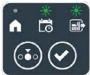
natural_image
Icon set with home, calendar, and checkmark symbols on dark background (no text or numbers)

natural_image
Icon set with home, calendar, and checkmark symbols on dark background (no text or numbers)
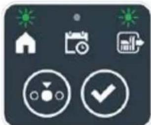
natural_image
Icon set with home, calendar, and checkmark symbols on dark background (no text or numbers)
STIGA
Postup:
text_image
A C D B
STOP
I L
E F G
text_image
A C D B
STOP
M
5.3.6. ZOBRAZENÍ STAVŮ ALARMŮ - IKONA ALARMU
text_image
A C D B
STOP
N
E
5.3.7. ZOBRAZENÍ NABITÍ BATERIE - IKONA BATERIE
natural_image
3D diagram of a device with a mesh base and a magnified inset showing a green indicator finger pointing to a component labeled 'N' (no text or symbols on the main diagram)
5.5. NABÍJEČKA AKUMULÁTORU
text_image
A C B R S
O
E
5.6. NASTAVENÍ VÝŠKY SEČENÍ
natural_image
Diagram of green grasses with X and Y axis labels (no text or symbols on the grass itself)
Postup:
text_image
A C D B
STOP
P Q
6. ÚDRŽBA
6.1. PLÁNOVANÁ ÚDRŽBA
natural_image
Diagram of a robotic vehicle showing internal components and a labeled point D (no text or symbols present)

UPOZORNĚNÍ:
text_image
Labeled diagram of a tracked vehicle showing components F, E, and G with visible parts and motion indicators.

text_image
H
I
6.3. VÝMĚNA SEKACÍCH NOŽŮ

text_image
Technical diagram of a robotic vehicle showing internal components and labeled parts (D, E, D)
6.4. ZIMNÍ ÚDRŽBA AKUMULÁTORU A USKLADNĚNÍ
Postup:
natural_image
3D rendering of a robotic vacuum cleaner with a circular vent and handle (no text or symbols visible)
6.5. VÝMĚNA AKUMULÁTORU
(Supply of Machinery (Safety) Regulations 2008, S.I. 2008 No. 1597, Annex II, part A)
-
The company: ST. S.p.A. – Via del Lavoro, 6 – 31033 Castelfranco Veneto (TV) – Italy
-
Hereby declares under its own responsibility that the machine:
Robotic lawnmower
a) Homologation type: SRSW01
c) Serial number: 22A••RMO000001 ÷ 99L••RMO999999
d) Engine: battery-operated
- Conforms to UK Regulations:
• S.I. 2008/1597 - Supply of Machinery (Safety) Regulations 2008
• S.I. 2016/1091 - Electromagnetic Compatibility Regulations 2016
- S.I. 2012/3032 - The Restriction of the Use of Certain Hazardous Substances in Electrical and Electronic Equipment Regulations 2012
• S.I. 2017/1206 - Radio Equipment Regulations 2017
- Reference to harmonised standards:
EN 60335-1:2012 / AC:2014 / A11:2014 / A13:2017 / EN 61000-3-2:2019
A1:2019 / A2:2019 / A14:2019 EN 61000-3-3:2013 / A1:2019
EN IEC 63000:2018 EN 300 328 V2.2.2
EN 303 447 V1.2.0
EN 50636-107:2015 / A1 / A2
EN 301 489-17 V3.2.4
EN 62479:2010
EN 55014-1:2017 / A11:2020
EN 55014-2:2015
i) Cutting width: 18 cm
n) Person authorised to compile the technical file: ST. S.p.A.
Via del Lavoro, 6
31033 Castelfranco Veneto (TV) - Italia
o) Castelfranco Veneto, 01/12/2022 CEO Stiga Group
ST. S.p.A.
Via del Lavoro, 6
31033 Castelfranco Veneto (TV) - Italia
Sean Robinson
UK Importer: STIGA LTD
Unit 8, Bluewater Estate Plympton,
Devon, PL7 4JH, England
171514280/1
| FR (Traduction de la notice originale)Déclaration CE de Conformité (Directive Machines 2006/42/CE, Annexe II, partie A)1. La Société2. Déclare sous sa propre responsabilité que la machine : Robot-tondeusea) Type / Modèle de Basec) Série d) Moteur: batterie3. Est conforme aux prescriptions des directives :4. Renvoi aux Normes harmoniséesi) Largeur de coupen) Personne habilitée à établir le Dossier Technique :o) Lieu et Date | DE (Übersetzung der Originalbetriebsanleitung)EG-Konformitätserklärung (Maschinenrichtlinie 2006/42/EG, Anhang II, Teil A)1. Die Gesellschaft2. Erklärt auf eigene Verantwortung, dass die Maschine: Mährobotera) Typ / Basismodellc) Seriennummerd) Motor: Batterie3. Den Anforderungen der folgenden Richtlinien entspricht:4. Bezugnahme auf die harmonisierten Normeni) Schnittbreiten) Zur Verfassung der technischen Unterlagen befugte Person:o) Ort und Datum | NL (Vertaling van de oorspronkelijke gebruiksaanwijzing)EG-verklaring van overeenstemming (Richtlijn Machines 2006/42/CE, Bijlage II, deel A)1. Het bedrijf2. Verklaart onder zijn eigen verantwoordelijkheid dat de machine: Robotmaaiera) Type / Basismodelc) Serienummerd) Motor: accu3. Voldoet aan de specificaties van der richtlijnen:4. Verwijzing naar de Geharmoniseerde normeni) Snijbreedten) Bevoegd persoon voor het opstellen van het Technisch Dossiero) Plaats en Datum |
| ES (Traducción del Manual Original)Declaración de Conformidad CE (Directiva Máquinas 2006/42/CE, Anexo II, parte A)1. La Empresa2. Declara bajo su propia responsabilidad que la máquina: Robot cortacéspeda) Tipo / Modelo Basec) Matrículad) Motor: bateria3. Cumple con las especificaciones de las directivas:4. Referencia a las Normas armonizadasi) Amplitud de corten) Persona autorizada a realizar el Manual Técnico:o) Lugar y Fecha | PT (Tradução do manual original)Declaração CE de Conformidade (Diretiva de Máquinas 2006/42/CE, Anexo II, parte A)1. A Empresa2. Declara sob a própria responsabilidade que a máquina: Robot corta-relvaa) Tipo / Modelo Basec) Matrículad) Moto: Bateria3. É conforme às especificações das diretivas:4. Referência às Normas harmonizadasi) Amplitude de corten) Pessoa autorizada a elaborar o Caderno Técnicoo) Local e Data | NO (Oversettelse av original bruksanvisning)EF- Samvarserklæring (Maskindirektiv 2006/42/EF, Vedlegg II, del A)1. Firmaet2. Erklærer på eget ansvar at maskinen: Robotgressklippera) Type / Modellc) Serienummerd) Motor: batteri3. Oppfyller kravene i direktivene:4. Henvisning til harmoniserte standarderI) Klippebredden) Person som har fullmakt til å ufterdige teknisk dokumentasjon:o) Sted og dato |
| SV (Översättning av bruksanvisning i original)EG-försäkran om överensstämmelse (Maskindirektiv 2006/42//EG, bilaga II, dela)1. Företaget2. Försäkrar på eget ansvar att maskinen: Gräsklipparrobota) Typ / Basmodellc) Serienummerd) Motor: batteri3. Överensstämmer med föreskrifterna i direktivet4. Referens till harmoniserade standarderi) Skärbreddn) Auktoriserad person för upprättandet av den tekniska dokumentationen:o) Ort och datum | DA (Översættelse af den originale brugsanvisning)EF-overensstemmelseserklæring (Maskindirektiv 2006/42/EF, bilag II, del A)1. Firmaet2. Erklærer på eget ansvar, at maskinen: Robotplænekllippera) Type / Modelc) Serienummerd) Motor: batteri3. Er i overensstemmelse med specifikationerne ifølge direktiverne:4. Henvisning til harmoniserede standarderi) Klippebredden) Person, der har bemyndigelse til at udarbejde det tekniske dossier:o) Sted og dato | FI (Alkuperäisten ohjeiden käännös)EY-VAATIMUSTENMUKAISUUSVAKUUTUS (Konedirektiivi 2006/42/EY, Liite II, osa A)1. Yritys2. Vakuuttaa omalla vastuullaan, että kone: Robottiruohonlelikkurla) Tyyppl / Perusmalllc) Sarjanumerod) Moottori : akku3. On yhdenmukainen seuraavien direktiivien asettamien vaatimusten kanssa:4. Viittaus harmonisoituihin standardeihini) Leikkuuleveysn) Teknisten asiakirjojen laatimiseenvaltuutettu henkilö:o) Paikka ja päivämäärä |
| SL (Prevod izvirnih navodil)ES izjava o skladnosti (Direktiva 2006/42/ES) , priloga II, del A)1. Družba2. pod lastno odgovornostjo izjavlja, da je stroj: Robotska kosilnicaa) Tip / osnovni modelc) Serijska številkad) Motor: baterija3. Skladen je z določili direktiv :4. Sklicevanje na usklajene predpisei) Obseg košnjen) Oseba, pooblaščena za sestavotehnične knjižice:o) Kraj In datum | LT (Originalių instrukciju vertimas)EB atitikties deklaracija (Mašinų direktyva 2006/42/CE, Priedas II, dalis A)1. Bendrovė2. Prisilma atsakomybę, kad jrenglnys: Žolės pjovimo robotasa) Tipas / Bazinis Modelisc) Serijos numerisd) Variklis: baterija3. Atitinka direktyvose pateiktas specifikacijas:4. Nuoroda i suderintas Normasi) Pjovimo plotisn) Autorizuotas asmuo sudaryti Techninę Dokumentaciją:o) Vieta ir Data | LV (Instrukciju tulkojums no originálvalodas)EK atbilstības deklarācija (Direktīva 2006/42/EK par mašinām, pleilkums II, daļa A)1. Uzņēmums2. Uzņemoties par to pilnu atbildību, pazino, ka mašina: Robotizēta pljaujmašinaa) Tips / Bāzes modelsc) Sērijas numursd) Motors: akumulators3. Atbilst šādu direktīvu prasībām:4. Atsauce uz harmonizētiem standartiemi) Plaušanas platumsn) Pilnvarotais darbinieks, kas sagatavoja tehnisko dokumentāciju:o) Vieta un datums |
| CS (Překlad původního návodu k používání)ES – Prohlášení o shodě(Směrnice o Strojních zařízeních 2006/42/ES, Přiloha II, část A)1. Společnost2. Prohlášuje na vlastní odpovědnost, že stroj: Robotická sekačkaa) Typ / Základní modelc) Výrobní číslod) Motor: akumulátor3. Je ve shodě s nařízeními směrnic:4. Odkazy na Harmonizované normyi) Šířka řezánín) Osoba autorizovaná pro vytvoření Technického spisu:o) Misto a Datum | PL (Tłumaczenie instrukcji oryginalnej)Deklaracja zgodności WE(Dyrektywa maszynowa 2006/42/WE,Załącznik II, część A)1. Spółka2. Oświadcza na własną odpowiedzialność, że maszyna: Kosiarka trawnikowaa) Typ / Model podstawowyc) Numer seryjnyd) Silnik: akumulator3. Spełnia podstawowe wymogi następujących Dyrektyw:4. Odniesienie do Norm zharmonizowanychi) Szerokość cięcia n) Osoba upoważniona do zredagowania Dokumentacji technicznej:o) Miejscowość i data | ET (Algupārase kasutusjuhendi tõlge)EÜ vastavusdeklaratsioon(Masinadirektiiv 2006/42/EÜ, Lisa II, osa A)1. Firma2. Kinnitab omal vastutusel, et masin:Robotniiduka) Tüüp / Põhimudel c) Matrikkeld) Mootor: aku3. Vastab direktiivide nõuetele:4. Viide ühtlustatud standarditelei) Lõikelaiusn) Tehnilise Lehe autoriseeritud koostaja:o) Koht ja Kuupäev |
| HU (Eredeti használati utasítás fordítása)EK-megfelelőségi nyilatkozata(2006/42/EK gépirányelv, ll. melléklet "A" rész)1. Alulírott Vállalat2. Felelősségének teljes tudatában kijelenti, hogy az alábbi gép: Robotfűnyíróa) Típus / Alaptipusc) Gyártási számd) Motor: akkumulátor3. Megfelel az alábbi irányelvekelőírásainak:4. Hivatkozás a harmonizált szabványokrai) Vágási szélességn) Műszaki Dosszié szerkesztésérefelhatalmazott személy:o) Helye és ideje | RU (Перевод оригинальных инструкций)Декларация соответствия нормам EC (Direktiva o машинном оборудовании 2006/42/EC, Приложение II, часть A)1. Предприятие2. Заявляет под собственную ответственность, что машина: Робот-газонокосилкаa) Тип / Базовая модельc) Паспортd) Двигатель: батарея сгорания3. Соответствует требованиям следующих директив:4. Ссылки на гармонизированные нормыi) Амплитуда кошенияn) Лицо, уполномоченное на подготовку технической документации:o) Место и дата | HR (Prijevod originalnih uputa)EK Izjava o sukladnosti(Direktiva 2006/42/EZ o strojevima, dodatak II, dio A)1. Tvrtka:2. pod vlastitom odgovornošću izjavljuje da je stroj: Robotska kosilicaa) Vrsta / Osnovni modelc) Matični brojd) Motor: baterija3. sukladan s temeljnim zahtjevima direktiva:4. Primijenjene su slijedeće harmonizirane norme:i) Širina rezanján) Osoba ovlaštena za pravljenje Tehničke datoteke:o) Mjesto i datum |
| SR (Prevod originalnih uputstval)EC deklaracija o usaglašenosti (Direktiva o mašinama 2006/42/EC, Prilog II, deo A)1. Preduzeće2. Daje izjavu pod vlastitom odgovornošćuda je mašina: Robot kosačicaa) Tip / Osnovni modelc) Serijski brojd) Motor: akumulator3. U skladu s osnovnim zahtevima direktiva:4. Pozivanje na usklađene normei) Širina košenjan) Osoba ovlašćena za sastavljanje tehničke brošureo) Mesto i datum | TR (Orijinal Talimatların Tercümesi)AT Uygunluk Beyanı (2006/42/CE Makine Direktifi, Ek II, bölüm A)1. Şirket2. Şahsi sorumluluğu altında aşağıdaki makinenin: Robot çim biçme makinesia) Tip / Standart modelc) Sicil numarasıd) Motor : batarya3. Aşağıdaki direktiflerin özelliklerine uygun olduğunu beyan etmektedir:4. Harmonize standartlara atifi) Kesim genişligiń) Teknik Dosyayı oluşturmaya yetkili kişi:o) Yer ve Tarih | RO (Traducerea manualului fabricantului)CE -Declaratie de Conformitate (Directiva Mašini 2006/42/CE, Anexa II, partea A)1. Societatea2. Declară pe propria răspundere că mașina: Robot mașină de tuns iarbaa) Tip / Model de bazăc) Număr de seried) Motor: baterie3. Este în conformitate cu specificațiile directivelor:4. Referință la Standardele armonizatei) Lătimea de täieren) Persoană autorizată să întocmeascăDosarul Tehnico) Locul și Data |
STIGA
STIGA LTD (UK Importer)
Unit 8, Bluewater Estate Plympton, Devon, PL7 4JH, England
STIGA S.p.A.
Via del lavoro, 6
31033 Castelfranco Veneto (TV)
Italy

FR
natural_image
Two yellow and gray StiGA robotic vacuum cleaner units (no visible text or symbols)
POLSKI - TŁUMACZENIE INSTRUKCJI ORYGINALNEJ
SPIS TREŚCI
1. MODELE I DANE TECHNICZNE 1
1.1. MODELE....1
1.2. DANE TECHNICZNE 2
2. BEZPIECZEŃSTWO 3
2.1. INFORMACJE DOTYCZĄCE BEZPIECZEŃSTWA....3
2.2. INSTRUKCJE BEZPIECZEŃSTWA....5
2.2.1. DOBRE PRAKTYKI BEZPIECZEŃSTWA....5
2.2.2. FUNKCJONOWANIE ....5
2.3. ZATRZYMYWANIE I WYŁĄCZANIE KOSIARKI AUTOMATYCZNEJ W WARUNKACH BEZPIECZEŃSTWA 7
3. WPROWADZENIE 8
3.1. WSTĘP OGÓLNY 8
3.1.1. CEL INSTRUKCJI....8
3.1.2. INSTRUKCJA CZYTANIA ZE SMARTFONA 8
3.2. OPIS PRODUKTU 9
3.2.1. OPIS OGÓLNY 9
3.2.2. GŁÓWNE CZĘŚCI 10
3.3. ROZPAKOWANIE 11
3.4. SYMBOLE I TABLICZKI 12
3.5. OGÓLNE WSKAZÓWKI DOTYCZĄCE INSTRUKCJI....13
4. INSTALACJA 14
4.1. OGÓLNE INFORMACJE DOTYCZĄCE INSTALACJI....14
4.2. CZEŚCI DO ZAINSTALOWANIA....14
4.3. WERYFIKACJA WYMAGAŃ INSTALACYJNYCH 15
4.3.1. WERYFIKACJA OGRODU: 15
4.3.2. WERYFIKACJA DO INSTALACJI STACJI ŁADUJĄCEJ I ZASILACZA: 15
4.3.3. GŁÓWNE KONTROLE PODCZAS INSTALACJI PRZEWODU OBWODOWEGO: 17
4.4. KRYTERIA INSTALACJI PRZEWODU OBWODOWEGO....19
4.4.1. UKŁADANIE PRZEWODU OBWODOWEGO.... 19
4.4.2. OGRANICZANIE PRZESZKÓD: 21
4.4.3. PRZEJŚCIA MIĘDZY RÓŻNYMI STREFAMI OGRODU 23
4.5. INSTALACJA CZĘŚCI....23
4.5.1. INSTALACJA PRZEWODU OBWODOWEGO....24
4.5.2. ŁĄCZENIE PRZEWODU OBWODOWEGO.... 25
4.5.3. INSTALACJA STACJI ŁADUJĄCEJ 26
4.5.4. INSTALACJA REZYSTORA DLA NIEWIELKICH OBWODÓW 28
4.6. ŁADOWANIE KOSIARKA TRAWNIKOWA PO INSTALACJI....29
4.7. USTAWIENIA PRODUKTU....30
5. FUNKCJONOWANIE
5.1. KONTROLA ZABEZPIECZEŃ W CELU URUCHOMIENIA KOSIARKI AUTOMATYCZNEJ 35
5.2. RĘCZNA OBSŁUGA KOSIARKI AUTOMATYCZNEJ 36
5.3. OPIS POLECEŃ OBECNYCH NA KOSIARCE AUTOMATYCZNEJ 37
5.3.1. BEZPIECZNE ZATRZYMANIE - PRZYCISK STOP 37
5.3.2. BEZPIECZNE WYŁĄCZANIE - KLUCZ BEZPIECZEŃSTWA 38
5.3.3. WŁĄCZANIE I WYŁĄCZANIE - PRZYCISK ON/OFF 38
5.3.4. WYBÓR PROGRAMU ZAPLANOWANEGO/ POJEDYNCZEGO CYKLU PRACY - PRZYCISK ZAPLANOWANY PROGRAM.... 39
5.3.5. WYŚWIETLANIE STANU BLUETOOTH I ODŁĄCZANIE - PRZYCISK BLUETOOTH 41
5.3.6. WYŚWIETLANIE STANÓW ALARMU - IKONA ALARMU 41
5.3.7. WYŚWIETLANIE STANU NAŁADOWANIA AKUMULATORA – IKONA AKUMULATORA 42
5.3.8. URUCHAMIANIE KOSIARKI - PRZYCISK START....42
5.4. FUNKCJONOWANIE STACJI ŁADUJĄCEJ 43
5.5. ŁADOWARKA AKUMULATORA 43
5.6. REGULACJA WYSOKOŚĆ KOSZENIA 44
6. KONSERWACJA 45
6.1. ZAPROGRAMOWANA KONSERWACJA 45
6.2. CZYSZCZENIE PRODUKTU 46
6.3. WYMIANA NOŻY TNĄCYCH....48
6.4. KONSERWACJA AKUMULATORA NA OKRES ZIMOWY I PRZECHOWYWANIE 49
6.5. WYMIANA AKUMULATORA 49
7. ROZWIĄZYWANIE PROBLEMÓW 50
7.1. GŁÓWNE KOMUNIKATY Z APLIKACJI 51
8. TRANSPORT, PRZECHOWYWANIE I UTYLIZACJA 53
8.1. TRANSPORT....53
8.2. PRZECHOWYWANIE 53
8.3. UTYLIZACJA 53
9. AKCESORIA 54
- GWARANCJA 55
10.1.ZAKRES GWARANCJI....55
- DEKLARACJA ZGODNOŚCI CE 56
1. MODELE I DANE TECHNICZNE
1.1. MODELE
natural_image
Line drawing of a robotic vacuum cleaner (no text or symbols)

natural_image
Technical line drawing of a tracked robotic vehicle showing internal components and mounting hardware (no text or symbols)
natural_image
Technical diagram showing two components: a mechanical housing labeled D and a rectangular device labeled E connected by wires (no text or symbols beyond labels)
text_image
Diagram showing four labeled components: coiled wire, test tube, mechanical component, and plastic clamp.
3.3. ROZPAKOWANIE
text_image
Safety warning signs and robot diagram with Chinese labels for hazard, safety, vehicle, and pictograms

OSTRZEŻENIE:
text_image
Diagram showing four symbols: battery pack, recycling symbol, no-renewable waste bin, and water-related cross.

OSTRZEŻENIE:
text_image
Labeled diagram of electrical components including a power iron, cable, and various screw and nut parts with numbered labels.
4.3. WERYFIKACJA WYMAGAŃ INSTALACYJNYCH
text_image
Diagram showing a device mounted on a wall with a ruler and a mouse, labeled with dimension 'X' and figure marker (B)
4.3.3. GŁÓWNE KONTROLE PODCZAS INSTALACJI PRZEWODU OBWODOWEGO
text_image
Diagram illustrating plant growth in a pond with labeled points G and F, showing green plants and water levels.
4.4. KRYTERIA INSTALACJI PRZEWODU OBWODOWEGO
4.4.1. UKŁADANIE PRZEWODU OBWODOWEGO
Procedura:
text_image
F
D
X3
F
E
X3
STIGA
text_image
O
P
M
x6
O
P
N
x6

POUCZENIE:
flowchart
graph TD
    A["Central Structure"] --> B["Arrow to U"]
    B --> C["Star-like Elements"]
    C --> D["Arrow to Right"]
    D --> E["Arrow to Left"]
    E --> F["Arrow to Right"]
    F --> G["Arrow to Left"]
    G --> H["Arrow to Right"]
    H --> I["Arrow to Left"]
    I --> J["Arrow to Right"]
    J --> K["Arrow to Left"]
    K --> L["Arrow to Right"]
    L --> M["Arrow to Left"]
    M --> N["Arrow to Right"]
    N --> O["Arrow to Left"]
    O --> P["Arrow to Right"]
    P --> Q["Arrow to Left"]
    Q --> R["Arrow to Right"]
    R --> S["Arrow to Left"]
    S --> T["Arrow to Right"]
    T --> U["Arrow to Left"]
    U --> V["Arrow to Right"]
    V --> W["Arrow to Left"]
    W --> X["Arrow to Right"]
    X --> Y["Arrow to Left"]
    Y --> Z["Arrow to Right"]
natural_image
Illustration of a robotic device and tree trunk with labeled parts (Z and V), no text or symbols present.
4.4.3. PRZEJŚCIA MIĘDZY RÓŻNYMI STREFAMI OGRODU
Procedura:
text_image
Diagram illustrating the process of hairpin tool application, showing steps from pinning to cutting and holding a hairpin.
STIGA
text_image
Technical diagram of a mechanical assembly with labeled parts L, C, and M, showing screw installation and component layout.

natural_image
3D diagram of a device with a green indicator light and a magnified view showing internal components (no text or symbols)
natural_image
Diagram of a red electrical fuse with a labeled terminal (no text or symbols present)

text_image
D2
C
O
I
E2E2
4.6. ŁADOWANIE KOSIARKI AUTOMATYCZNEJ PO INSTALACJI
Wymagania i nakazy:
- Stacja ładująca.
Procedura:
| G 300 G 600 G | 1200 | |
| Border Cut | | | |
| Go-To Cut Points | 1 3 5 | | |
| Eco Mode | | | |
| Rain Sensor | | | |
| Closed Area | | | |
SPIS USTAWIEN PRODUKTU
4.7.1. PRELOGIN 31
4.7.2. REJESTRACJA (SIGN UP) 31
4.7.3. KOJARZENIE (PAIRING) 31
4.7.4. STRONA PRODUKTU (DEVICE PAGE) 32
4.7.5. OBSZAR ZAMKNIETY (CLOSED AREA) 32
4.7.6. USTAWIENIA (SETTINGS) 32
4.7.7. KOSZENIE POJEDYNCZE / ZAPROGRAMOWANE (SPOT CUT / SCHEDULED) 32
4.7.8. SESJE KOSZENIA (MOWING SESSIONS) 32
4.7.9. GO-TO-CUT POINTS 33
4.7.10. CIĘCIE OBRZEŻA (BORDER CUT) 33
4.7.11. ECO MODE....33
4.7.12. CZUJNIK DESZCZU (RAIN SENSOR) (W ZALEŻNOŚCI OD MODELU) 33
4.7.13. BLOKADA KLAWIATURY (APP LOCK) 33
4.7.14. ZARZĄDZANIE UŻYTKOWNIKAMI 35
4.7.15. SPRZEDAWCY (DEALER) 35
4.7.16. WIADOMOŚCI (MESSAGES).... 35
4.7.17. PROFIL (PROFILE) 35
4.7.1. WSTĘPNE LOGOWANIE
text_image
A
B D E C
STOP
5.2. RĘCZNA OBSŁUGA KOSIARKI AUTOMATYCZNEJ
text_image
A C D B
STOP
L
E F G
text_image
A C D B
O H I L N
E F G M
text_image
A C D B
STOP
E
5.3.4. WYBRAĆ ZAPLANOWANY PROGRAM / POJEDYNCZY CYKL PRACY / WYMUSZONY POWRÓT DO STACJI ŁADUJĄCEJ - PRZYCISK WYBORU TRYBU
natural_image
Icon set with home, calendar, and checkmark symbols (no text or numbers)

natural_image
Icon set with home, calendar, and checkmark symbols (no text or numbers)

natural_image
Icon set with home, calendar, and checkmark symbols (no text or numbers)

natural_image
Icon set with home, calendar, and checkmark symbols on dark background (no text or numbers)

natural_image
Icon set with home, camera, and checklist symbols (no text or numbers)
STIGA
Procedura:
text_image
A C D B
STOP
I L
E F G
text_image
A C D B
STOP
M
5.3.6. WYŚWIETLANIE STANÓW ALARMU - IKONA ALARMU
text_image
A C D B
STOP
N
E
5.3.7. WYŚWIETLANIE STANU NAŁADOWANIA AKUMULATORA - IKONA AKUMULATORA
natural_image
3D diagram of a device with a labeled component (N) and a magnified inset showing a green button, no text or symbols present.
5.5. ŁADOWANIE AKUMULATORA
text_image
A C B R S
O
E
5.6. REGULACJA WYSOKOŚĆ KOSZENIA
natural_image
Diagram showing two green grasses with X and Y axis labels (no text or symbols on the grass itself)
Procedura:
text_image
A C D B
STOP
P Q
6. KONSERWACJA
6.1. ZAPROGRAMOWANA KONSERWACJA
natural_image
Diagram of a robotic vehicle with labeled parts (D) and internal components, no readable text or symbols present.

text_image
Labeled diagram of a tracked vehicle showing key components: F, E, and G.
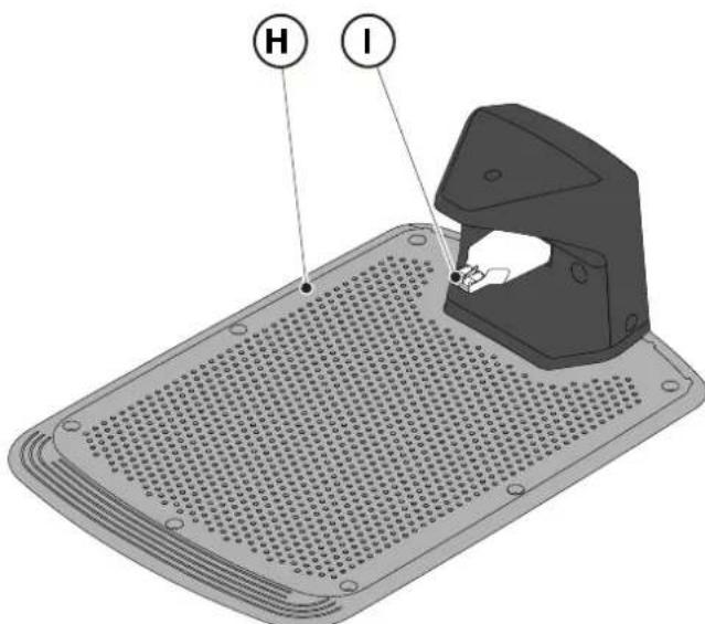
text_image
H
I
6.3. WYMIANA NOŻY TNĄCYCH

text_image
Technical diagram of a robotic vehicle showing internal components and labeled parts (D, E, D)
6.4. KONSERWACJA AKUMULATORA NA OKRES ZIMOWY I PRZECHOWYWANIE
Procedura:
natural_image
3D rendering of a gray robotic device with a black lid and circular base (no text or symbols visible)
6.5. WYMIANA AKUMULATORA
(Supply of Machinery (Safety) Regulations 2008, S.I. 2008 No. 1597, Annex II, part A)
- The company: ST. S.p.A. – Via del Lavoro, 6 – 31033 Castelfranco Veneto (TV) – Italy
- Hereby declares under its own responsibility that the machine:
Robotic lawnmower
a) Homologation type: SRSW01
c) Serial number: 22A••RMO000001 ÷ 99L••RMO999999
d) Engine: battery-operated
- Conforms to UK Regulations:
• S.I. 2008/1597 - Supply of Machinery (Safety) Regulations 2008
• S.I. 2016/1091 - Electromagnetic Compatibility Regulations 2016
• S.I. 2012/3032 - The Restriction of the Use of Certain Hazardous Substances in Electrical and Electronic Equipment Regulations 2012
• S.I. 2017/1206 - Radio Equipment Regulations 2017
- Reference to harmonised standards:
EN 60335-1:2012 / AC:2014 / A11:2014 / A13:2017 / EN 61000-3-2:2019
A1:2019 / A2:2019 / A14:2019 EN 61000-3-3:2013 / A1:2019
EN IEC 63000:2018 EN 300 328 V2.2.2
EN 303 447 V1.2.0
EN 50636-107:2015 / A1 / A2
EN 301 489-17 V3.2.4
EN 62479:2010
EN 55014-1:2017 / A11:2020
EN 55014-2:2015
i) Cutting width: 18 cm
n) Person authorised to compile the technical file: ST. S.p.A.
Via del Lavoro, 6
31033 Castelfranco Veneto (TV) - Italia
o) Castelfranco Veneto, 01/12/2022 CEO Stiga Group
ST. S.p.A.
Via del Lavoro, 6
31033 Castelfranco Veneto (TV) - Italia
Sean Robinson

UK Importer:
STIGA LTD
Unit 8, Bluewater Estate Plympton,
Devon, PL7 4JH, England

| FR (Traduction de la notice originale)Déclaration CE de Conformité (Directive Machines 2006/42/CE, Annexe II, partie A)1. La Société2. Déclare sous sa propre responsabilité que la machine : Robot-tondeusea) Type / Modèle de Basec) Série d) Moteur: batterie3. Est conforme aux prescriptions des directives :4. Renvoi aux Normes harmoniséesi) Largeur de coupen) Personne habilitée à établir le Dossier Technique :o) Lieu et Date | DE (Übersetzung der Originalbetriebsanleitung)EG-Konformitätserklärung (Maschinenrichtlinie 2006/42/EG, Anhang II, Teil A)1. Die Gesellschaft2. Erklärt auf eigene Verantwortung, dass die Maschine: Mährobotera) Typ / Basismodellc) Seriennummerd) Motor: Batterie3. Den Anforderungen der folgenden Richtlinien entspricht:4. Bezugnahme auf die harmonisierten Normeni) Schnittbreiten) Zur Verfassung der technischen Unterlagen befugte Person:o) Ort und Datum | NL (Vertaling van de oorspronkelijke gebruiksaanwijzing)EG-verklaring van overeenstemming (Richtlijn Machines 2006/42/CE, Bijlage II, deel A)1. Het bedrijf2. Verklaart onder zijn eigen verantwoordelijkheid dat de machine: Robotmaaiera) Type / Basismodelc) Serienummerd) Motor: accu3. Voldoet aan de specificaties van derichtlijnen:4. Verwijzing naar de Geharmoniseerde normeni) Snijbreedten) Bevoegd persoon voor het opstellen van het Technisch Dossiero) Plaats en Datum |
| ES (Traducción del Manual Original)Declaración de Conformidad CE (Directiva Máquinas 2006/42/CE, Anexo II, parte A)1. La Empresa2. Declara bajo su propia responsabilidad que la máquina: Robot cortacéspeda) Tipo / Modelo Basec) Matrículad) Motor: bateria3. Cumple con las especificaciones de las directivas:4. Referencia a las Normas armonizadasi) Amplitud de corten) Persona autorizada a realizar el Manual Técnico:o) Lugar y Fecha | PT (Tradução do manual original)Declaração CE de Conformidade (Diretiva de Máquinas 2006/42/CE, Anexo II, parte A)1. A Empresa2. Declara sob a própria responsabilidade que a máquina: Robot corta-relvaa) Tipo / Modelo Basec) Matrículad) Moto: Bateria3. É conforme às especificações das diretivas:4. Referência às Normas harmonizadasi) Amplitude de corten) Pessoa autorizada a elaborar o Caderno Técnicoo) Local e Data | NO (Oversettelse av original bruksanvisning)EF- Samvarserklæring (Maskindirektiv 2006/42/EF, Vedlegg II, del A)1. Firmaet2. Erklærer på eget ansvar at maskinen: Robotgressklippera) Type / Modellc) Serienummerd) Motor: batteri3. Oppfyller kravene i direktivene:4. Henvisning til harmoniserte standarderI) Klippebredden) Person som har fullmakt til å ufterdige teknisk dokumentasjon:o) Sted og dato |
| SV (Översättning av bruksanvisning i original)EG-försäkran om överensstämmelse (Maskindirektiv 2006/42//EG, bilaga II, dela)1. Företaget2. Försäkrar på eget ansvar att maskinen: Gräsklipparrobota) Typ / Basmodellc) Serienummerd) Motor: batteri3. Överensstämmer med föreskrifterna i direktivet4. Referens till harmoniserade standarderi) Skärbreddn) Auktoriserad person för upprättandet av den tekniska dokumentationen:o) Ort och datum | DA (Översættelse af den originale brugsanvisning)EF-overensstemmelseserklæring (Maskindirektiv 2006/42/EF, bilag II, del A)1. Firmaet2. Erklærer på eget ansvar, at maskinen: Robotplænekllippera) Type / Modelc) Serienummerd) Motor: batteri3. Er i overensstemmelse med specifikationerne ifølge direktiverne:4. Henvisning til harmoniserede standarderi) Klippebredden) Person, der har bemyndigelse til at udarbejde det tekniske dossier:o) Sted og dato | FI (Alkuperäisten ohjeiden käännös)EY-VAATIMUSTENMUKAISUUSVAKUUTUS (Konedirektiivi 2006/42/EY, Liite II, osa A)1. Yritys2. Vakuuttaa omalla vastuullaan, että kone: Robottiruohonlelikkurla) Tyyppl / Perusmalllc) Sarjanumerod) Moottori : akku3. On yhdenmukainen seuraavien direktiivien asettamien vaatimusten kanssa:4. Viittaus harmonisoituihin standardeihini) Leikkuuleveysn) Teknisten asiakirjojen laatimiseenvaltuutettu henkilö:o) Paikka ja päivämäärä |
| SL (Prevod izvirnih navodil)ES izjava o skladnosti (Direktiva 2006/42/ES) , priloga II, del A)1. Družba2. pod lastno odgovornostjo izjavlja, da je stroj: Robotska kosilnicaa) Tip / osnovni modelc) Serijska številkad) Motor: baterija3. Skladen je z določili direktiv :4. Sklicevanje na usklajene predpisei) Obseg košnjen) Oseba, pooblaščena za sestavotehnične knjižice:o) Kraj In datum | LT (Originalių instrukciju vertimas)EB atitikties deklaracija (Mašinų direktyva 2006/42/CE, Priedas II, dalis A)1. Bendrovė2. Prisilma atsakomybę, kad jrenglnys: Žolės pjovimo robotasa) Tipas / Bazinis Modelisc) Serijos numerisd) Variklis: baterija3. Atitinka direktyvose pateiktas specifikacijas:4. Nuoroda i suderintas Normasi) Pjovimo plotisn) Autorizuotas asmuo sudaryti Techninę Dokumentaciją:o) Vieta ir Data | LV (Instrukciju tulkojums no originálvalodas)EK atbilstības deklarācija (Direktīva 2006/42/EK par mašinām, pleilkums II, daļa A)1. Uzņēmums2. Uzņemoties par to pilnu atbildību, pazino, ka mašina: Robotizēta pljaujmašinaa) Tips / Bāzes modelsc) Sērijas numursd) Motors: akumulators3. Atbilst šādu direktīvu prasībām:4. Atsauce uz harmonizētiem standartiemi) Pljaušanas platumsn) Pilnvarotais darbinieks, kas sagatavoja tehnisko dokumentāciju:o) Vieta un datums |
| CS (Překlad původního návodu k používání)ES – Prohlášení o shodě(Směrnice o Strojních zařízeních 2006/42/ES, Přiloha II, část A)1. Společnost2. Prohlášuje na vlastní odpovědnost, že stroj: Robotická sekačkaa) Typ / Základní modelc) Výrobní číslod) Motor: akumulátor3. Je ve shodě s nařízeními směrnic:4. Odkazy na Harmonizované normyi) Šířka řezánín) Osoba autorizovaná pro vytvoření Technického spisu:o) Misto a Datum | PL (Tłumaczenie instrukcji oryginalnej)Deklaracja zgodności WE(Dyrektywa maszynowa 2006/42/WE,Załącznik II, część A)1. Spółka2. Oświadczenie na własną odpowiedzialność, że maszyna: Kosiarka trawnikowaa) Typ / Model podstawowyc) Numer seryjnyd) Silnik: akumulator3. Spełnia podstawowe wymogi następujących Dyrektyw:4. Odniesienie do Norm zharmonizowanychi) Szerokość cięcia n) Osoba upoważniona do zredagowania Dokumentacji technicznej:o) Miejscowość i data | ET (Algupārase kasutusjuhendi tõlge)EÜ vastavusdeklaratsioon(Masinadirektiiv 2006/42/EÜ, Lisa II, osa A)1. Firma2. Kinnitab omal vastutusel, et masin:Robotniiduka) Tüüp / Põhimudel c) Matrikkeld) Mootor: aku3. Vastab direktiivide nõuetele:4. Viide ühtlustatud standarditelei) Lõikelaiusn) Tehnilise Lehe autoriseeritud koostaja:o) Koht ja Kuupäev |
| HU (Eredeti használati utasítás fordítása)EK-megfelelőségi nyilatkozata(2006/42/EK gépirányelv, ll. melléklet "A" rész)1. Alulírott Vállalat2. Felelősségének teljes tudatában kijelenti, hogy az alábbi gép: Robotfűnyíróa) Típus / Alaptipusc) Gyártási számd) Motor: akkumulátor3. Megfelel az alábbi irányelvekelőírásainak:4. Hivatkozás a harmonizált szabványokrai) Vágási szélességn) Műszaki Dosszié szerkesztésérefelhatalmazott személy:o) Helye és ideje | RU (Перевод оригинальных инструкций)Декларация соответствия нормам EC (Direktiva o машинном оборудовании 2006/42/EC, Приложение II, часть A)1. Предприятие2. Заявляет под собственную ответственность, что машина: Робот-газонокосилкаa) Тип / Базовая модельc) Паспортd) Двигатель: батарея сгорания3. Соответствует требованиям следующих директив:4. Ссылки на гармонизированные нормыi) Амплитуда кошенияn) Лицо, уполномоченное на подготовку технической документации:o) Место и дата | HR (Prijevod originalnih uputa)EK Izjava o sukladnosti(Direktiva 2006/42/EZ o strojevima, dodatak II, dio A)1. Tvrtka:2. pod vlastitom odgovornošću izjavljuje da je stroj: Robotska kosilicaa) Vrsta / Osnovni modelc) Matični brojd) Motor: baterija3. sukladan s temeljnim zahtjevima direktiva:4. Primijenjene su slijedeće harmonizirane norme:i) Širina rezanján) Osoba ovlaštena za pravljenje Tehničke datoteke:o) Mjesto i datum |
| SR (Prevod originalnih uputstval)EC deklaracija o usaglašenosti (Direktiva o mašinama 2006/42/EC, Prilog II, deo A)1. Preduzeće2. Daje izjavu pod vlastitom odgovornošćuda je mašina: Robot kosačicaa) Tip / Osnovni modelc) Serijski brojd) Motor: akumulator3. U skladu s osnovnim zahtevima direktiva:4. Pozivanje na usklađene normei) Širina košenjan) Osoba ovlašćena za sastavljanje tehničke brošureo) Mesto i datum | TR (Orijinal Talimatların Tercümesi)AT Uygunluk Beyanı (2006/42/CE Makine Direktifi, Ek II, bölüm A)1. Şirket2. Şahsi sorumluluğu altında aşağıdaki makinenin: Robot çim biçme makinesia) Tip / Standart modelc) Sicil numarasıd) Motor : batarya3. Aşağıdaki direktiflerin özelliklerine uygun olduğunu beyan etmektedir:4. Harmonize standartlara atifi) Kesim genişligiń) Teknik Dosyayı oluşturmaya yetkili kişi:o) Yer ve Tarih | RO (Traducerea manualului fabricantului)CE -Declaratie de Conformitate (Directiva Mašini 2006/42/CE, Anexa II, partea A)1. Societatea2. Declară pe propria răspundere că mașina: Robot mașină de tuns iarbaa) Tip / Model de bazăc) Număr de seried) Motor: baterie3. Este în conformitate cu specificațiile directivelor:4. Referință la Standardele armonizatei) Lătimea de täieren) Persoană autorizată să întocmeascăDosarul Tehnico) Locul și Data |
STIGA
STIGA LTD (UK Importer)
Unit 8, Bluewater Estate Plympton, Devon, PL7 4JH, England
STIGA S.p.A.
Via del lavoro, 6
31033 Castelfranco Veneto (TV)
Italy
stiga.com

FR
natural_image
Two yellow and gray STIGA robotic vacuum cleaner units (no visible text or symbols)
natural_image
Line drawing of a robotic vacuum cleaner (no text or symbols)

natural_image
Technical line drawing of a tracked robotic vehicle showing internal components and mounting hardware (no text or symbols)
1.2. MÜSZAKI ADATOK
natural_image
Two electronic components: a mechanical housing labeled D and a battery-like device labeled E, with no visible text or symbols.
text_image
Diagram showing four labeled components: coiled wire, cap with pins, mechanical component, and plastic clamp.
3.3. KICSOMAGOLÁS
flowchart
graph TD
    A["Open Cart Box 123"] --> B["Box with lid"]
    B --> C["Shawn with lid"]
    C --> D["Robot with stopper and filter"]
    D --> E["Robot with filter"]
3.4. SZIMBÓLUMOK ÉS ADATTÁBLÁK
text_image
Safety warning signs and a robotic device with Chinese labels, including warning symbols for accidents, safety measures, and no-discrimination.

FIGYELEM:
text_image
Diagram showing four symbols: battery pack, recycling symbol, no-renewable waste bin, and water-related warning sign.

FIGYELEM:
text_image
Diagram showing labeled components of a mechanical or electrical device, including an iron iron, cable, and screw assembly.
4.3. A TELEPÍTÉS FELTÉTELEINEK ELLENŐRZÉSE
text_image
Diagram illustrating a vehicle safety scenario with labeled points A, B, C and distance markers x and x, including a box and checkmark indicators.

FIGYELEM:
text_image
Diagram illustrating plant growth in a pond with labeled points G and F, showing green plants and water level.
4.4. A HATÁROLÓ HUZAL TELEPÍTÉSÉNEK SZEMPONTJAI
4.4.1. A HATÁROLÓ HUZAL ELHELYEZÉSE
Eljárás:
text_image
F
D
X3
F
E
X3
STIGA
text_image
O
P
M
x6
O
P
N
x6

FIGYELMEZTETÉS:
flowchart
graph TD
    A["Central Structure"] --> B["Arrow to U"]
    B --> C["Star-like Elements"]
    C --> D["Arrow to Right"]
    D --> E["Arrow to Left"]
    E --> F["Arrow to Right"]
    F --> G["Arrow to Left"]
    G --> H["Arrow to Right"]
    H --> I["Arrow to Left"]
    I --> J["Arrow to Right"]
    J --> K["Arrow to Left"]
    K --> L["Arrow to Right"]
    L --> M["Arrow to Left"]
    M --> N["Arrow to Right"]
    N --> O["Arrow to Left"]
    O --> P["Arrow to Right"]
    P --> Q["Arrow to Left"]
    Q --> R["Arrow to Right"]
    R --> S["Arrow to Left"]
    S --> T["Arrow to Right"]
    T --> U["Arrow to Left"]
    U --> V["Arrow to Right"]
    V --> W["Arrow to Left"]
    W --> X["Arrow to Right"]
    X --> Y["Arrow to Left"]
    Y --> Z["Arrow to Right"]
natural_image
Illustration of a robotic device and tree trunk with labeled parts (Z and V), no text or symbols present.
4.4.3. ÁTJÁRÓK A KERT KÜLÖNBÖZŐ ZÓNÁI KÖZÖTT
Eljárás:
text_image
A
R=20 cm

text_image
B
100 cm
FÖLD ALÁ BEÁSOTT TELEPÍTÉS
(CSAK A FELHATALMAZOTT MÁRKAKERESKEDŐ VÉGEZHETI EL)
text_image
Diagram illustrating the process of hairpin tool application, showing steps from pinning to cutting and holding a hairpin.
STIGA
text_image
Technical diagram of a mechanical assembly with labeled parts L, C, and M, showing screw installation and component layout.
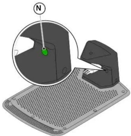
natural_image
3D diagram of a mechanical device with a green indicator light and a magnified view showing internal components (no text or symbols)
text_image
Diagram of a red electrical fuse with labeled terminal and pin points

text_image
D2
C
O
I
E2E2
4.6. A ROBOTFÚNYÍRÓ FELTÖLTÉSE A TELEPÍTÉST KÖVETŐEN
| G 300 G 600 G | 1200 | |
| Border Cut | | | |
| Go-To Cut Points | 1 3 5 | | |
| Eco Mode | | | |
| Rain Sensor | | | |
| Closed Area | | | |
A TERMÉK BEÁLLÍTÁSAINAK TARTALOMJEGYZÉKE
4.7.1. PRELOGIN 31
4.7.2. REGISZTRÁCIÓ (SIGN UP) 31
text_image
A
B
C
D
E
STOP
5.2. A ROBOTFÜNYÍRÓ KÉZI ÜZEMMÓDJA
text_image
A C D B
STOP
L
E F G
text_image
A C D B
O H I L N
E F G M
5.3.1. BIZTONSÁGI LEÁLLÍTÁS - STOP GOMB
text_image
A C D B
STOP
E
natural_image
Icon set with home, calendar, and checkmark symbols (no text or numbers)
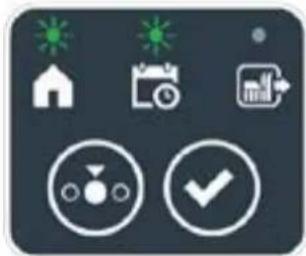
natural_image
Icon set with home, calendar, and checkmark symbols (no text or numbers)

natural_image
Icon set with home, calendar, and checkmark symbols (no text or numbers)
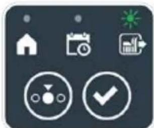
natural_image
Icon set with home, calendar, and checkmark symbols on dark background (no text or numbers)
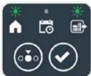
natural_image
Icon set with home, calendar, and checkmark symbols (no text or numbers)
Eljárás:
text_image
A C D B
STOP
I L
E F G
text_image
A C D B
STOP
M
text_image
A C D B
STOP
N
E
5.3.7. AZ AKKUMULÁTOR TÖLTÉSÉNEK KIJELZÉSE - AKKUMULÁTOR IKON
text_image
A C D B
STOP
O
5.3.8. A ROBOTFÚNYÍRÓ BEINDÍTÁSA
natural_image
3D diagram of a device with a labeled component (N) and an inset showing a green button on a surface (no text or symbols present)
5.5. AZ AKKUMULÁTOR FELTÖLTÉSE
text_image
A C B R S
O
E
natural_image
Diagram showing two green grasses with X and Y axis labels (no text or symbols on the grass itself)
Eljárás:
text_image
A C D B
STOP
P Q
6. KARBANTARTÁS
natural_image
Diagram of a robotic vehicle showing internal components and a labeled point D (no text or symbols present)

FIGYELEM:
text_image
Labeled diagram of a tracked vehicle showing components F, E, and G with visible parts and motion indicators.

text_image
H
I
6.3. A VÁGÓKÉSEK CSERÉJE

text_image
Technical diagram of a robotic vehicle showing labeled components and assembly view
natural_image
3D rendering of a gray robotic device with a black handle and circular base (no text or symbols visible)
6.5. AZ AKKUMULÁTOR CSERÉJE
(Supply of Machinery (Safety) Regulations 2008, S.I. 2008 No. 1597, Annex II, part A)
- The company: ST. S.p.A. – Via del Lavoro, 6 – 31033 Castelfranco Veneto (TV) – Italy
- Hereby declares under its own responsibility that the machine:
Robotic lawnmower
a) Homologation type: SRSW01
c) Serial number: 22A••RMO000001 ÷ 99L••RMO999999
d) Engine: battery-operated
- Conforms to UK Regulations:
• S.I. 2008/1597 - Supply of Machinery (Safety) Regulations 2008
• S.I. 2016/1091 - Electromagnetic Compatibility Regulations 2016
- S.I. 2012/3032 - The Restriction of the Use of Certain Hazardous Substances in Electrical and Electronic Equipment Regulations 2012
• S.I. 2017/1206 - Radio Equipment Regulations 2017
- Reference to harmonised standards:
EN 60335-1:2012 / AC:2014 / A11:2014 / A13:2017 / EN 61000-3-2:2019
A1:2019 / A2:2019 / A14:2019 EN 61000-3-3:2013 / A1:2019
EN IEC 63000:2018 EN 300 328 V2.2.2
EN 303 447 V1.2.0
EN 50636-107:2015 / A1 / A2
EN 301 489-17 V3.2.4
EN 62479:2010
EN 55014-1:2017 / A11:2020
EN 55014-2:2015
i) Cutting width: 18 cm
n) Person authorised to compile the technical file: ST. S.p.A.
Via del Lavoro, 6
31033 Castelfranco Veneto (TV) - Italia
o) Castelfranco Veneto, 01/12/2022 CEO Stiga Group
ST. S.p.A.
Via del Lavoro, 6
31033 Castelfranco Veneto (TV) - Italia
Sean Robinson

UK Importer:
STIGA LTD
Unit 8, Bluewater Estate Plympton,
Devon, PL7 4JH, England

| FR (Traduction de la notice originale)Déclaration CE de Conformité (Directive Machines 2006/42/CE, Annexe II, partie A)1. La Société2. Déclare sous sa propre responsabilité que la machine : Robot-tondeusea) Type / Modèle de Basec) Série d) Moteur: batterie3. Est conforme aux prescriptions des directives :4. Renvoi aux Normes harmoniséesi) Largeur de coupen) Personne habilitée à établir le Dossier Technique :o) Lieu et Date | DE (Übersetzung der Originalbetriebsanleitung)EG-Konformitätserklärung (Maschinenrichtlinie 2006/42/EG, Anhang II, Teil A)1. Die Gesellschaft2. Erklärt auf eigene Verantwortung, dass die Maschine: Mährobotera) Typ / Basismodellc) Seriennummerd) Motor: Batterie3. Den Anforderungen der folgenden Richtlinien entspricht:4. Bezugnahme auf die harmonisierten Normeni) Schnittbreiten) Zur Verfassung der technischen Unterlagen befugte Person:o) Ort und Datum | NL (Vertaling van de oorspronkelijke gebruiksaanwijzing)EG-verklaring van overeenstemming (Richtlijn Machines 2006/42/CE, Bijlage II, deel A)1. Het bedrijf2. Verklaart onder zijn eigen verantwoordelijkheid dat de machine: Robotmaaiera) Type / Basismodelc) Serienummerd) Motor: accu3. Voldoet aan de specificaties van der richtlijnen:4. Verwijzing naar de Geharmoniseerde normeni) Snijbreedten) Bevoegd persoon voor het opstellen van het Technisch Dossiero) Plaats en Datum |
| ES (Traducción del Manual Original)Declaración de Conformidad CE (Directiva Máquinas 2006/42/CE, Anexo II, parte A)1. La Empresa2. Declara bajo su propia responsabilidad que la máquina: Robot cortacéspeda) Tipo / Modelo Basec) Matrículad) Motor: bateria3. Cumple con las especificaciones de las directivas:4. Referencia a las Normas armonizadasi) Amplitud de corten) Persona autorizada a realizar el Manual Técnico:o) Lugar y Fecha | PT (Tradução do manual original)Declaração CE de Conformidade (Diretiva de Máquinas 2006/42/CE, Anexo II, parte A)1. A Empresa2. Declara sob a própria responsabilidade que a máquina: Robot corta-relvaa) Tipo / Modelo Basec) Matrículad) Moto: Bateria3. É conforme às especificações das diretivas:4. Referência às Normas harmonizadasi) Amplitude de corten) Pessoa autorizada a elaborar o Caderno Técnicoo) Local e Data | NO (Oversettelse av original bruksanvisning)EF- Samvarserklæring (Maskindirektiv 2006/42/EF, Vedlegg II, del A)1. Firmaet2. Erklærer på eget ansvar at maskinen: Robotgressklippera) Type / Modellc) Serienummerd) Motor: batteri3. Oppfyller kravene i direktivene:4. Henvisning til harmoniserte standarderI) Klippebredden) Person som har fullmakt til å ufterdige teknisk dokumentasjon:o) Sted og dato |
| SV (Översättning av bruksanvisning i original)EG-försäkran om överensstämmelse (Maskindirektiv 2006/42//EG, bilaga II, dela)1. Företaget2. Försäkrar på eget ansvar att maskinen: Gräsklipparrobota) Typ / Basmodellc) Serienummerd) Motor: batteri3. Överensstämmer med föreskrifterna i direktivet4. Referens till harmoniserade standarderi) Skärbreddn) Auktoriserad person för upprättandet av den tekniska dokumentationen:o) Ort och datum | DA (Översættelse af den originale brugsanvisning)EF-overensstemmelseserklæring (Maskindirektiv 2006/42/EF, bilag II, del A)1. Firmaet2. Erklærer på eget ansvar, at maskinen: Robotplæneklippera) Type / Modelc) Serienummerd) Motor: batteri3. Er i overensstemmelse med specifikationerne ifølge direktiverne:4. Henvisning til harmoniserede standarderi) Klippebredden) Person, der har bemyndigelse til at udarbejde det tekniske dossier:o) Sted og dato | FI (Alkuperäisten ohjeiden käännös)EY-VAATIMUSTENMUKAISUUSVAKUUTUS (Konedirektiivi 2006/42/EY, Liite II, osa A)1. Yritys2. Vakuuttaa omalla vastuullaan, että kone: Robottiruohonlelikkurla) Tyyppl / Perusmalllc) Sarjanumerod) Moottori : akku3. On yhdenmukainen seuraavien direktiivien asettamien vaatimusten kanssa:4. Viittaus harmonisoituihin standardeihini) Leikkuuleveysn) Teknisten asiakirjojen laatimiseenvaltuutettu henkilö:o) Paikka ja päivämäärä |
| SL (Prevod izvirnih navodil)ES izjava o skladnosti (Direktiva 2006/42/ES) , priloga II, del A)1. Družba2. pod lastno odgovornostjo izjavlja, da je stroj: Robotska kosilnicaa) Tip / osnovni modelc) Serijska številkad) Motor: baterija3. Skladen je z določili direktiv :4. Sklicevanje na usklajene predpisei) Obseg košnjen) Oseba, pooblaščena za sestavotehnične knjižice:o) Kraj In datum | LT (Originalių instrukciju vertimas)EB atitikties deklaracija (Mašinų direktyva 2006/42/CE, Priedas II, dalis A)1. Bendrovė2. Prisilma atsakomybę, kad jrenglnys: Žolės pjovimo robotasa) Tipas / Bazinis Modelisc) Serijos numerisd) Variklis: baterija3. Atitinka direktyvose pateiktas specifikacijas:4. Nuoroda i suderintas Normasi) Pjovimo plotisn) Autorizuotas asmuo sudaryti Techninę Dokumentaciją:o) Vieta ir Data | LV (Instrukciju tulkojums no originálvalodas)EK atbilstības deklarācija (Direktīva 2006/42/EK par mašinām, pleilkums II, daļa A)1. Uzņēmums2. Uzņemoties par to pilnu atbildību, pazino, ka mašina: Robotizēta pljaujmašinaa) Tips / Bāzes modelsc) Sērijas numursd) Motors: akumulators3. Atbilst šādu direktīvu prasībām:4. Atsauce uz harmonizētiem standartiemi) Plaušanas platumsn) Pilnvarotais darbinieks, kas sagatavoja tehnisko dokumentāciju:o) Vieta un datums |
| CS (Překlad původního návodu k používání)ES – Prohlášení o shodě(Směrnice o Strojních zařízeních 2006/42/ES, Přiloha II, část A)1. Společnost2. Prohlašuje na vlastní odpovědnost, že stroj: Robotická sekačkaa) Typ / Základní modelc) Výrobní číslod) Motor: akumulátor3. Je ve shodě s nařizeními směrnic:4. Odkazy na Harmonizované normyi) Šířka řezánín) Osoba autorizovaná pro vytvoření Technického spisu:o) Misto a Datum | PL (Tłumaczenie instrukcji oryginalnej)Deklaracja zgodności WE(Dyrektywa maszynowa 2006/42/WE,Załącznik II, część A)1. Spółka2. Oświadcza na własną odpowiedzialność, że maszyna: Kosiarka trawnikowaa) Typ / Model podstawowyc) Numer seryjnyd) Silnik: akumulator3. Spełnia podstawowe wymogi następujących Dyrektyw:4. Odniesienie do Norm zharmonizowanychi) Szerokość cięciań) Osoba upoważniona do zredagowania Dokumentacji technicznej:o) Miejscowość i data | ET (Algupārase kasutusjuhendi tõlge)EÜ vastavusdeklaratsioon(Masinadirektiiv 2006/42/EÜ, Lisa II, osa A)1. Firma2. Kinnitab omal vastutusel, et masin:Robotniiduka) Tüüp / Põhimudel c) Matrikkeld) Mootor: aku3. Vastab direktiivide nõuetele:4. Viide ühtlustatud standarditelei) Lõikelaiusn) Tehnilise Lehe autoriseeritud koostaja:o) Koht ja Kuupäev |
| HU (Eredeti használati utasítás fordítása)EK-megfelelőségi nyilatkozata(2006/42/EK gépirányelv, ll. melléklet "A" rész)1. Alulírott Vállalat2. Felelősségének teljes tudatában kijelenti, hogy az alábbi gép: Robotfűnyíróa) Típus / Alaptípusc) Gyártási számd) Motor: akkumulátor3. Megfelel az alábbi irányelvekelőirásainak:4. Hivatkozás a harmonizált szabványokrai) Vágási szélességn) Múszaki Dosszié szerkesztésérefelhatalmazott személy:o) Helye és ideje | RU (Перевод оригинальных инструкций)Декларация соответствия нормам EC(Директива о машинном оборудовании 2006/42/EC, Приложение II, часть A)1. Предприятие2. Заявляет под собственную ответственность, что машина: Робот-газонокосилкаa) Тип / Базовая модельc) Паспортd) Двигатель: батарея сгорания3. Соответствует требованиям следующих директив:4. Ссылки на гармонизированные нормыi) Амплитуда кошенияn) Лицо, уполномоченное на подготовку технической документации:o) Место и дата | HR (Prijevod originalnih uputa)EK Izjava o sukladnosti(Direktiva 2006/42/EZ o strojevima,dodatak II, dio A)1. Tvrtka:2. pod vlastitom odgovornošću izjavljujeda je stroj: Robotska kosilicaa) Vrsta / Osnovni modelc) Matični brojd) Motor: baterija3. sukladan s temeljnim zahtjevimadirektiva:4. Primijenjene su slijedeće harmonizirane norme:i) Širina rezanján) Osoba ovlaštena za pravljenje Tehničke datoteke:o) Mjesto i datum |
| SR (Prevod originalnih uputstval)EC deklaracija o usaglašenosti(Direktiva o mašinama 2006/42/EC, Prilog II, deo A)1. Preduzeće2. Daje izjavu pod vlastitom odgovornošćuda je mašina: Robot kosačicaa) Tip / Osnovni modelc) Serijski brojd) Motor: akumulator3. U skladu s osnovnim zahtevimadirektiva:4. Pozivanje na uskladene normei) Širina košenjan) Osoba ovlašćena za sastavljanjetehničke brošureo) Mesto i datum | TR (Orijinal Talimatların Tercümesi)AT Uygunluk Beyanı(2006/42/CE Makine Direktifi, Ek II, bölüm A)1. Şirket2. Şahsi sorumluluğu altında aşağıdaki makinenin: Robot çim biçme makinesia) Tip / Standart modelc) Sicil numarasıd) Motor : batarya3. Aşağıdaki direktiflerin özelliklerine uygun olduğunu beyan etmektedir:4. Harmonize standartlara atıfi) Kesim genişlígin) Teknik Dosyayı oluşturmaya yetkili kişi:o) Yer ve Tarih | RO (Traducerea manualului fabricantului)CE -Declaratie de Conformitate(Directiva Mașini 2006/42/CE, Anexa II, partea A)1. Societatea2. Declară pe propria răspundere că mașina: Robot mașină de tuns iarbaa) Tip / Model de bazăc) Număr de seried) Motor: baterie3. Este în conformitate cu specificațiiledirectivelor:4. Referință la Standardele armonizatei) Lătîmea de tăieren) Persoană autorizată să întocmeascăDosarul Tehnico) Locul și Data |
STIGA
STIGA LTD (UK Importer)
Unit 8, Bluewater Estate Plympton, Devon, PL7 4JH, England
STIGA S.p.A.
Via del lavoro, 6
31033 Castelfranco Veneto (TV)
Italy

FR
natural_image
Two yellow and gray ATIGA robotic vacuum cleaner units (no visible text or symbols)
EESTI KEEL - ITAALIAKEELSE ORIGINAALJUHENDI TÖLGE
SISUKORD
1. MUDELID JA TEHNILISED ANDMED 1
1.1. MUDELID....1
1.2. TEHNILISED ANDMED....2
2. OHUTUS 3
2.1. OHUTUSALANE TEAVE 3
2.2. OHUTUSEESKIRJAD....5
2.2.1. TURVALISED TÖÖVÖTTED....5
2.2.2. TÖÖPÖHIMÖTE 5
2.3. ROBOTNIIDUKI SEISKAMINE JA VÄLJALÜLITAMINE OHUTUSTINGIMUSTES 7
3. SISSEJUHATUS 8
3.1. ÜLDINE SISSEJUHATUS....8
3.1.1. JUHENDI EESMÄRK......8
3.1.2. JUHISED LUGEMISEKS NUTITELEFONIST 8
3.2. TOOTEÜLEVAADE....9
3.2.1. ÜLDINE KIRJELDUS....9
3.2.2. PÕHIKOMPONENDID 10
3.3. PAKENDIST VÄLJAVÖTMINE 11
3.4. SÜMBOLID JA ANDMEPLAADID....12
3.5. JUHENDI LUGEMISE ÜLDISED JUHISED 13
4. PAIGALDAMINE 14
4.1. ÜLDTEAVE PAIGALDAMISE KOHTA 14
4.2. PAIGALDAMISEKS VAJALIKUD KOMPONENDID 14
4.3. PAIGALDAMISNÕUETE KONTROLLIMINE....15
4.3.1. AIA KONTROLLIMINE: 15
4.3.2. KONTROLLID LAADIMISJAAMA JA TOITESEADME PAIGALDAMISEKS: 15
4.3.3. PÖHIKONTROLLID PIIREKAABLI PAIGALDAMISEKS: 17
4.4. PIIRDEKAABLI PAIGALDAMISE KRITEERIUMID....19
4.4.1. PIIRDEKAABLI KOHALE ASETAMINE 19
4.4.2. TAKISTUSTE PIIRITLEMINE: 21
4.4.3. ÜLEMINEKUD AIA ERI ALADE VAHEL 23
4.5. KOMPONENTIDE PAIGALDAMINE....23
4.5.1. PIIRDEKAABLI PAIGALDAMINE....24
4.5.2. PIIRDEKAABLI JÄTKAMINE 25
4.5.3. LAADIMISJAAMA PAIGALDAMINE 26
4.5.4. RESISTORI PAIGALDAMINE VÄIKESTE PERIMEETRITE JAOKS....28
4.6. ROBOTNIIDUKI LAADIMINE PÄRAST PAIGALDAMIST....29
4.7. TOOTE SEADISTUSED....30
5. TÖÖPÕHIMÕTE 35
5.1. TURVASEADISTE KONTROLLIMINE ROBOTNIIDUKI KÄIVITAMISEKS....35
5.2. ROBOTNIIDUKI MANUAALNE TÖÖTAMINE 36
5.3. ROBOTNIIDUKI JUHTSEADMETE KIRJELDUS 37
5.3.1. OHUTU SEISKAMINE - STOP NUPP 37
5.3.2. KUSTUTAMINE OHUTUSTINGIMUSTES - TURVAVÕTI 38
5.3.3. SISSE- JA VÄLJALÜLITAMINE - NUPP ON/OFF.... 38
5.3.4. KAVANDATUD PROGRAMMI / ÜKSIKU TÖÖTSÜKLI VALIMINE – KAVANDATUD PROGRAMMI NUPP ..... 39
5.3.5. BLUETOOTHI OLEKU KUVAMINE JA LAHTI ÜHENDAMINE - NUPP BLUETOOTH.... 41
5.3.6. ALARMIOLEKUTE KUVAMINE - ALARMIIKOON 41
5.3.7. AKU LAETUSE OLEKU KUVAMINE - AKU IKOON 42
5.3.8. ROBOTNIIDUKI KÄIVITAMINE - NUPP START 42
5.4. LAADIMISJAAMA TÖÖTAMINE 43
5.5. AKU LAADIMINE....43
5.6. NIITMISKÖRGUSE REGULEERIMINE....44
6. HOOLDUS 45
6.1. KORRALINE HOOLDUS 45
6.2. TOOTE PUHASTAMINE 46
6.3. LÕIKETERADE VAHETAMINE......48
6.4. AKU TALVEKS HOOLDAMINE JA HOIULE PANEMINE 49
6.5. AKU VAHETAMINE....49
7. PROBLEEMIDE LAHENDAMINE 50
7.1. PEAMISED ÄPI TEATED....51
8. TRANSPORT, LADUSTAMINE JA KÖRVALDAMINE 53
8.1. TRANSPORT 53
8.2. HOIDMINE 53
8.3. KÖRVALDAMINE....53
9. LISASEADMED 54
- GARANTII 55
10.1. GARANTII KATE ....55
- EÜ VASTAVUSDEKLARATSIOON 56
1. MUDELID JA TEHNILISED ANDMED
1.1. MUDELID
natural_image
Line drawing of a TiGA robotic vacuum cleaner (no text or symbols on body)

natural_image
Technical line drawing of a robotic vehicle showing internal components and mounting hardware (no text or symbols)
1.2. TEHNILISED ANDMED
natural_image
Illustration of a 4018 robotic device with labeled point A and light trail, set against a green background (no text or symbols on the device itself)
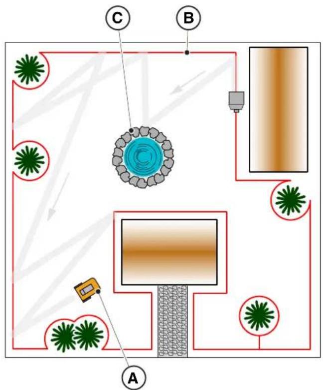
flowchart
graph TD
    A["Environment Area"] --> B["Central Room"]
    B --> C["Building Area"]
    C --> D["Storage Area"]
    D --> E["Storage Area"]
    E --> F["Storage Area"]
    F --> G["Storage Area"]
    G --> H["Storage Area"]
    H --> I["Storage Area"]
    I --> J["Storage Area"]
    J --> K["Storage Area"]
    K --> L["Storage Area"]
    L --> M["Storage Area"]
    M --> N["Storage Area"]
    N --> O["Storage Area"]
    O --> P["Storage Area"]
    P --> Q["Storage Area"]
    Q --> R["Storage Area"]
    R --> S["Storage Area"]
    S --> T["Storage Area"]
    T --> U["Storage Area"]
    U --> V["Storage Area"]
    V --> W["Storage Area"]
    W --> X["Storage Area"]
    X --> Y["Storage Area"]
    Y --> Z["Storage Area"]
    Z --> AA["Storage Area"]
    AA --> AB["Storage Area"]
    AB --> AC["Storage Area"]
    AC --> AD["Storage Area"]
    AD --> AE["Storage Area"]
    AE --> AF["Storage Area"]
    AF --> AG["Storage Area"]
    AG --> AH["Storage Area"]
    AH --> AI["Storage Area"]
    AI --> AJ["Storage Area"]
3.2.2. PÕHIKOMPONENDID
natural_image
Technical diagram showing two components: a mechanical housing labeled D and a rectangular device labeled E connected by wires (no text or symbols beyond labels)
text_image
Diagram showing four labeled components: coiled wire, plastic cup with pins, mechanical component, and plastic clamp.
3.3. LAHTIPAKKIMINE
flowchart
graph TD
    A["Open Cart Box"] --> B["Box"]
    B --> C["Shipped Cart Box"]
    C --> D["Robot with Sensor"]
    D --> E["Processed Robot with Sensor"]
3.4. SÜMBOLID JA ANDMEPLAADID
text_image
Safety warning signs and a robotic device with Chinese labels, including warning symbols for accidents, safety measures, and pictograms.

TÄHELEPANU:
text_image
Diagram showing four types of waste management symbols: recycling, no litter, fire, and water discharge.
TÄHELEPANU:
text_image
Labeled diagram of electrical components including a power iron, cable, and various screw and nut parts with numbered labels.
4.3. PAIGALDAMISNÕUETE KONTROLLIMINE
text_image
Diagram illustrating a vehicle motion test setup with labeled components A, B, C and distance markers x and x̄

TÄHELEPANU:
text_image
Diagram showing a device mounted on a wall with a labeled component and coordinate system (X)
4.3.3. PÕHIKONTROLLID PIIREKAABLI PAIGALDAMISEKS
text_image
E
≥ 35cm
d
> 45%
X
STIGA

TÄHELEPANU:
text_image
Diagram illustrating plant growth in a pond with labeled points G and F, showing green plants and water levels.
4.4. PIIRDEKAABLI PAIGALDAMISE KRITEERIUMID
4.4.1. PIIRDEKAABLI KOHALE ASETAMINE
Toimimisviis:
text_image
O
P
M
x6
O
P
N
x6

HOIATUS:
flowchart
graph TD
    A["Central Structure"] --> B["Arrow to U"]
    B --> C["Star-like Elements"]
    C --> D["Arrow to Right"]
    D --> E["Arrow to Left"]
    E --> F["Arrow to Right"]
    F --> G["Arrow to Left"]
    G --> H["Arrow to Right"]
    H --> I["Arrow to Left"]
    I --> J["Arrow to Right"]
    J --> K["Arrow to Right"]
    K --> L["Arrow to Left"]
    L --> M["Arrow to Right"]
    M --> N["Arrow to Left"]
    N --> O["Arrow to Right"]
    O --> P["Arrow to Right"]
    P --> Q["Arrow to Left"]
    Q --> R["Arrow to Right"]
    R --> S["Arrow to Right"]
    S --> T["Arrow to Left"]
    T --> U["Arrow to Right"]
    U --> V["Arrow to Right"]
    V --> W["Arrow to Left"]
    W --> X["Arrow to Right"]
    X --> Y["Arrow to Right"]
natural_image
Illustration of a robotic vacuum cleaner and tree trunk with labeled parts (Z and V), no text or symbols present.
4.4.3. ÜLEMINEKUD AIA ERI ALADE VAHEL
Toimimisviis:
flowchart
graph TD
    A["Central Box"] --> B["Process Unit"]
    B --> C["Flow Line z"]
    C --> D["Green Star (Circle) at top"]
    C --> E["Green Star (Circle) at bottom"]
    C --> F["Gray Box (Circle)"] --> G["Arrow to Center"]
    G --> H["Arrow to Right"]
    H --> I["Arrow to Left"]
    I --> J["Arrow to Right"]
    J --> K["Arrow to Bottom"]
    K --> L["Arrow to Left"]
    L --> M["Arrow to Right"]
    M --> N["Arrow to Top"]
    N --> O["Arrow to Right"]
    O --> P["Arrow to Left"]
    P --> Q["Arrow to Right"]
    Q --> R["Arrow to Bottom"]
4.5. KOMPONENTIDE PAIGALDAMINE
text_image
A
R=20 cm

text_image
B
100 cm
PAIGALDAMINE MAA SISSE
(SEDA SAAB TEHA AINULT VOLITATUD EDASIMÜÜJA)
text_image
Diagram illustrating the process of hairpin tool application, showing steps from pinning to cutting and holding a hairpin.
STIGA
text_image
Technical diagram of a mechanical assembly with labeled parts L, C, and M, showing screw installation and component layout.
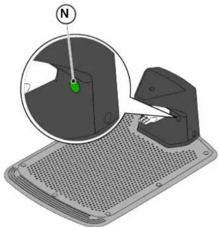
natural_image
3D diagram of a mechanical device with a green indicator light and a magnified view showing a component (no text or symbols)
natural_image
Diagram of a red electrical fuse or terminal block with a circular component and mounting holes (no text or symbols)

text_image
D2
C
O
I
E2E2
4.6. ROBOTNIIDUKI LAADIMINE PÄRAST PAIGALDAMIST
4.7. TOOTE SEADISTUSED
| G 300 G 600 G | 1200 | |
| Border Cut |  |  |  |
| Go-To Cut Points | 1 3 5 | | |
| Eco Mode |  |  |  |
| Rain Sensor |  |  |  |
| Closed Area |  |  |  |
TOOTE SEADISTUSTE INDEKS
4.7.1. EELLOGIN....31
4.7.2. REGISTREERIMINE (SIGN UP) 31
4.7.3. SIDUMINE (PAIRING) 31
4.7.4. TOOTE LEHEKÜLG (DEVICE PAGE) 32
4.7.5. SULETUD ALA (CLOSED AREA) 32
4.7.6. SEADISTUSED (SETTINGS) 32
4.7.7. ÜHEKORDNE NIITMINE / KAVANDATUD NIITMINE (SPOT CUT / SCHEDULED).... 32
4.7.8. NIITMISKORRAD (MOWING SESSIONS) 32
4.7.9. NIITMISKOHTADESSE SUUNAMINE GO-TO-CUT POINTS 33
4.7.10. SERVA NIITMINE (BORDER CUT) 33
4.7.6. SEADISTUSED (SETTINGS)
text_image
A
B
C
D
E
STOP
5.2. ROBOTNIIDUKI MANUAALNE TÖÖTAMINE
text_image
A C D B
STOP
L
E F G
text_image
A C D B
O H I L N
E F G M
5.3.1. OHUTU SEISKAMINE - STOPP NUPP
text_image
A C D B
STOP
E
5.3.4. KAVANDATUD PROGRAMMI / ÜKSIKU TÖÖTSÜKLI / LAADIMISJAAMA TAGASISAATMISE VALIMINE – REŽIIMIVALIKU NUPP
natural_image
Icon set with home, calendar, and checkmark symbols (no text or numbers)

natural_image
Icon set with home, calendar, and checkmark symbols (no text or numbers)

natural_image
Icon set with home, calendar, and checkmark symbols (no text or numbers)

natural_image
Icon set with home, calendar, and checkmark symbols (no text or numbers)

natural_image
Icon set with home, camera, and checklist symbols (no text or numbers)
STIGA
Toimimisviis:
text_image
A C D B
STOP
I L
E F G
text_image
A C D B
STOP
M
5.3.6. ALARMIOLEKUTE KUVAMINE - ALARMIIKOON
text_image
A C D B
STOP
O
5.3.8. ROBOTNIIDUKI KÄIVITAMINE
natural_image
3D diagram of a mechanical component with a magnified inset showing a green indicator finger and a labeled point N (no text or symbols beyond the label)
5.5. AKU LAADIMINE
text_image
A C B R S
O
E
5.6. NIITMISKÖRGUSE REGULEERIMINE
natural_image
Diagram of green grasses with X and Y axis labels (no text or symbols on the grass itself)
Toimimisviis:
text_image
A C D B
STOP
P Q
6. HOOLDAMINE
6.1. KORRALINE HOOLDUS
natural_image
Diagram of a robotic vehicle showing internal components and a labeled point D (no text or symbols present)

text_image
Labeled diagram of a tracked vehicle showing components F, E, and G with visible parts and motion indicators.

text_image
H
I
6.3. LÕIKETERADE VAHETAMINE

text_image
Technical diagram of a robotic vehicle showing internal components and labeled parts (D, E, D)
6.4. AKU TALVEKS HOOLDAMINE JA LADUSTAMINE
Toimimisviis:
natural_image
3D rendering of a robotic vacuum cleaner with a circular vent and handle (no text or symbols visible)
6.5. AKU VAHETAMINE
(Supply of Machinery (Safety) Regulations 2008, S.I. 2008 No. 1597, Annex II, part A)
- The company: ST. S.p.A. – Via del Lavoro, 6 – 31033 Castelfranco Veneto (TV) – Italy
- Hereby declares under its own responsibility that the machine:
Robotic lawnmower
a) Homologation type: SRSW01
c) Serial number: 22A••RMO000001 ÷ 99L••RMO999999
d) Engine: battery-operated
- Conforms to UK Regulations:
• S.I. 2008/1597 - Supply of Machinery (Safety) Regulations 2008
• S.I. 2016/1091 - Electromagnetic Compatibility Regulations 2016
- S.I. 2012/3032 - The Restriction of the Use of Certain Hazardous Substances in Electrical and Electronic Equipment Regulations 2012
• S.I. 2017/1206 - Radio Equipment Regulations 2017
- Reference to harmonised standards:
EN 60335-1:2012 / AC:2014 / A11:2014 / A13:2017 / EN 61000-3-2:2019
A1:2019 / A2:2019 / A14:2019 EN 61000-3-3:2013 / A1:2019
EN IEC 63000:2018 EN 300 328 V2.2.2
EN 303 447 V1.2.0
EN 50636-107:2015 / A1 / A2
EN 301 489-17 V3.2.4
EN 62479:2010
EN 55014-1:2017 / A11:2020
EN 55014-2:2015
i) Cutting width: 18 cm
n) Person authorised to compile the technical file: ST. S.p.A.
Via del Lavoro, 6
31033 Castelfranco Veneto (TV) - Italia
o) Castelfranco Veneto, 01/12/2022 CEO Stiga Group
ST. S.p.A.
Via del Lavoro, 6
31033 Castelfranco Veneto (TV) - Italia
Sean Robinson

UK Importer:
STIGA LTD
Unit 8, Bluewater Estate Plympton,
Devon, PL7 4JH, England

| FR (Traduction de la notice originale)Déclaration CE de Conformité (Directive Machines 2006/42/CE, Annexe II, partie A)1. La Société2. Déclare sous sa propre responsabilité que la machine : Robot-tondeusea) Type / Modèle de Basec) Série d) Moteur: batterie3. Est conforme aux prescriptions des directives :4. Renvoi aux Normes harmoniséesi) Largeur de coupen) Personne habilitée à établir le Dossier Technique :o) Lieu et Date | DE (Übersetzung der Originalbetriebsanleitung)EG-Konformitätserklärung (Maschinenrichtlinie 2006/42/EG, Anhang II, Teil A)1. Die Gesellschaft2. Erklärt auf eigene Verantwortung, dass die Maschine: Mährobotera) Typ / Basismodellc) Seriennummerd) Motor: Batterie3. Den Anforderungen der folgenden Richtlinien entspricht:4. Bezugnahme auf die harmonisierten Normeni) Schnittbreiten) Zur Verfassung der technischen Unterlagen befugte Person:o) Ort und Datum | NL (Vertaling van de oorspronkelijke gebruiksaanwijzing)EG-verklaring van overeenstemming (Richtlijn Machines 2006/42/CE, Bijlage II, deel A)1. Het bedrijf2. Verklaart onder zijn eigen verantwoordelijkheid dat de machine: Robotmaaiera) Type / Basismodelc) Serienummerd) Motor: accu3. Voldoet aan de specificaties van derichtlijnen:4. Verwijzing naar de Geharmoniseerde normeni) Snijbreedten) Bevoegd persoon voor het opstellen van het Technisch Dossiero) Plaats en Datum |
| ES (Traducción del Manual Original)Declaración de Conformidad CE (Directiva Máquinas 2006/42/CE, Anexo II, parte A)1. La Empresa2. Declara bajo su propia responsabilidad que la máquina: Robot cortacéspeda) Tipo / Modelo Basec) Matrículad) Motor: bateria3. Cumple con las especificaciones de las directivas:4. Referencia a las Normas armonizadasi) Amplitud de corten) Persona autorizada a realizar el Manual Técnico:o) Lugar y Fecha | PT (Tradução do manual original)Declaração CE de Conformidade (Diretiva de Máquinas 2006/42/CE, Anexo II, parte A)1. A Empresa2. Declara sob a própria responsabilidade que a máquina: Robot corta-relvaa) Tipo / Modelo Basec) Matrículad) Moto: Bateria3. É conforme às especificações das diretivas:4. Referência às Normas harmonizadasi) Amplitude de corten) Pessoa autorizada a elaborar o Caderno Técnicoo) Local e Data | NO (Oversettelse av original bruksanvisning)EF- Samvarserklæring (Maskindirektiv 2006/42/EF, Vedlegg II, del A)1. Firmaet2. Erklærer på eget ansvar at maskinen: Robotgressklippera) Type / Modellc) Serienummerd) Motor: batteri3. Oppfyller kravene i direktivene:4. Henvisning til harmoniserte standarderI) Klippebredden) Person som har fullmakt til å ufterdige teknisk dokumentasjon:o) Sted og dato |
| SV (Översättning av bruksanvisning i original)EG-försäkran om överensstämmelse (Maskindirektiv 2006/42//EG, bilaga II, dela)1. Företaget2. Försäkrar på eget ansvar att maskinen: Gräsklipparrobota) Typ / Basmodellc) Serienummerd) Motor: batteri3. Överensstämmer med föreskrifterna i direktivet4. Referens till harmoniserade standarderi) Skärbreddn) Auktoriserad person för upprättandet av den tekniska dokumentationen:o) Ort och datum | DA (Översættelse af den originale brugsanvisning)EF-overensstemmelseserklæring (Maskindirektiv 2006/42/EF, bilag II, del A)1. Firmaet2. Erklærer på eget ansvar, at maskinen: Robotplænekllippera) Type / Modelc) Serienummerd) Motor: batteri3. Er i overensstemmelse med specifikationerne ifølge direktiverne:4. Henvisning til harmoniserede standarderi) Klippebredden) Person, der har bemyndigelse til at udarbejde det tekniske dossier:o) Sted og dato | FI (Alkuperäisten ohjeiden käännös)EY-VAATIMUSTENMUKAISUUSVAKUUTUS (Konedirektiivi 2006/42/EY, Liite II, osa A)1. Yritys2. Vakuuttaa omalla vastuillaan, että kone: Robottiruohonlelikkurla) Tyyppl / Perusmalllc) Sarjanumerod) Moottori : akku3. On yhdenmukainen seuraavien direktiivien asettamien vaatimusten kanssa:4. Viittaus harmonisoituihin standardeihini) Leikkuuleveysn) Teknisten asiakirjojen laatimiseenvaltuutettu henkilö:o) Paikka ja päivämäärä |
| SL (Prevod izvirnih navodil)ES izjava o skladnosti (Direktiva 2006/42/ES) , priloga II, del A)1. Družba2. pod lastno odgovornostjo izjavlja, da je stroj: Robotska kosilnicaa) Tip / osnovni modelc) Serijska številkad) Motor: baterija3. Skladen je z določili direktiv :4. Sklicevanje na usklajene predpisei) Obseg košnjen) Oseba, pooblaščena za sestavotehnične knjižice:o) Kraj In datum | LT (Originalių instrukciju vertimas)EB atitikties deklaracija (Mašinų direktyva 2006/42/CE, Priedas II, dalis A)1. Bendrovė2. Prisilma atsakomybę, kad jrenglnys: Žolės pjovimo robotasa) Tipas / Bazinis Modelisc) Serijos numerisd) Variklis: baterija3. Atitinka direktyvose pateiktas specifikacijas:4. Nuoroda i suderintas Normasi) Pjovimo plotisn) Autorizuotas asmuo sudaryti Techninę Dokumentaciją:o) Vieta ir Data | LV (Instrukciju tulkojums no originálvalodas)EK atbilstības deklarācija (Direktīva 2006/42/EK par mašinām, pleilkums II, daļa A)1. Uzņēmums2. Uzņemoties par to pilnu atbildību, pazino, ka mašina: Robotizēta pljaujmašinaa) Tips / Bāzes modelsc) Sērijas numursd) Motors: akumulators3. Atbilst šādu direktīvu prasībām:4. Atsauce uz harmonizētiem standartiemi) Pljaušanas platumsn) Pilnvarotais darbinieks, kas sagatavoja tehnisko dokumentāciju:o) Vieta un datums |
| CS (Překlad původního návodu k používání)ES – Prohlášení o shodě(Směrnice o Strojních zařízeních 2006/42/ES, Přiloha II, část A)1. Společnost2. Prohlášuje na vlastní odpovědnost, že stroj: Robotická sekačkaa) Typ / Základní modelc) Výrobní číslod) Motor: akumulátor3. Je ve shodě s nařízeními směrnic:4. Odkazy na Harmonizované normyi) Šířka řezánín) Osoba autorizovaná pro vytvoření Technického spisu:o) Misto a Datum | PL (Tłumaczenie instrukcji oryginalnej)Deklaracja zgodności WE(Dyrektywa maszynowa 2006/42/WE,Załącznik II, część A)1. Spółka2. Oświadczenie na własną odpowiedzialność, że maszyna: Kosiarka trawnikowaa) Typ / Model podstawowyc) Numer seryjnyd) Silnik: akumulator3. Spełnia podstawowe wymogi następujących Dyrektyw:4. Odniesienie do Norm zharmonizowanychi) Szerokość cięcia n) Osoba upoważniona do zredagowania Dokumentacji technicznej:o) Miejscowość i data | ET (Algupārase kasutusjuhendi tõlge)EÜ vastavusdeklaratsioon(Masinadirektiiv 2006/42/EÜ, Lisa II, osa A)1. Firma2. Kinnitab omal vastutusel, et masin:Robotniiduka) Tüüp / Põhimudel c) Matrikkeld) Mootor: aku3. Vastab direktiivide nõuetele:4. Viide ühtlustatud standarditelei) Lõikelaiusn) Tehnilise Lehe autoriseeritud koostaja:o) Koht ja Kuupäev |
| HU (Eredeti használati utasítás fordítása)EK-megfelelőségi nyilatkozata(2006/42/EK gépirányelv, ll. melléklet "A" rész)1. Alulírott Vállalat2. Felelősségének teljes tudatában kijelenti, hogy az alábbi gép: Robotfűnyíróa) Típus / Alaptipusc) Gyártási számd) Motor: akkumulátor3. Megfelel az alábbi irányelvekelőírásainak:4. Hivatkozás a harmonizált szabványokrai) Vágási szélességn) Műszaki Dosszié szerkesztésérefelhatalmazott személy:o) Helye és ideje | RU (Перевод оригинальных инструкций)Декларация соответствия нормам EC (Direktiva o машинном оборудовании 2006/42/EC, Приложение II, часть A)1. Предприятие2. Заявляет под собственную ответственность, что машина: Робот-газонокосилкаa) Тип / Базовая модельc) Паспортd) Двигатель: батарея сгорания3. Соответствует требованиям следующих директив:4. Ссылки на гармонизированные нормыi) Амплитуда кошенияn) Лицо, уполномоченное на подготовку технической документации:o) Место и дата | HR (Prijevod originalnih uputa)EK Izjava o sukladnosti (Direktiva 2006/42/EZ o strojevima, dodatak II, dio A)1. Tvrtka:2. pod vlastitom odgovornošću izjavljuje da je stroj: Robotska kosilicaa) Vrsta / Osnovni modelc) Matični brojd) Motor: baterija3. sukladan s temeljnim zahtjevima direktiva:4. Primijenjene su slijedeće harmonizirane norme:i) Širina rezanján) Osoba ovlaštena za pravljenje Tehničke datoteke:o) Mjesto i datum |
| SR (Prevod originalnih uputstval)EC deklaracija o usaglašenosti (Direktiva o mašinama 2006/42/EC, Prilog II, deo A)1. Preduzeće2. Daje izjavu pod vlastitom odgovornošćuda je mašina: Robot kosačicaa) Tip / Osnovni modelc) Serijski brojd) Motor: akumulator3. U skladu s osnovnim zahtevima direktiva:4. Pozivanje na usklađene normei) Širina košenjan) Osoba ovlašćena za sastavljanje tehničke brošureo) Mesto i datum | TR (Orijinal Talimatların Tercümesi)AT Uygunluk Beyanı (2006/42/CE Makine Direktifi, Ek II, bölüm A)1. Şirket2. Şahsi sorumluluğu altında aşağıdaki makinenin: Robot çim biçme makinesia) Tip / Standart modelc) Sicil numarasıd) Motor : batarya3. Aşağıdaki direktiflerin özelliklerine uygun olduğunu beyan etmektedir:4. Harmonize standartlara atifi) Kesim genişligiń) Teknik Dosyayı oluşturmaya yetkili kişi:o) Yer ve Tarih | RO (Traducerea manualului fabricantului)CE -Declaratie de Conformitate (Directiva Mašini 2006/42/CE, Anexa II, partea A)1. Societatea2. Declară pe propria răspundere că mașina: Robot mașină de tuns iarbaa) Tip / Model de bazăc) Număr de seried) Motor: baterie3. Este în conformitate cu specificațiile directivelor:4. Referință la Standardele armonizatei) Lătimea de täieren) Persoană autorizată să întocmeascăDosarul Tehnico) Locul și Data |
STIGA
STIGA LTD (UK Importer)
Unit 8, Bluewater Estate Plympton, Devon, PL7 4JH, England
STIGA S.p.A.
Via del lavoro, 6
31033 Castelfranco Veneto (TV)
Italy

FR
natural_image
Two yellow and gray Stiga robotic vacuum cleaner units (no visible text or symbols)
HRVATSKI - PRIJEVOD ORIGINALNIH UPUTA
KAZALO
1. MODELI I TEHNIČKI PODACI 1
1.1. MODELI 1
1.2. TEHNIČKI PODACI 2
2. SIGURNOST 3
2.1. INFORMACIJE O SIGURNOSTI .... 3
2.2. SIGURNOSNE UPUTE....5
2.2.1. SIGURNA RADNA PRAKSA 5
2.2.2. RAD....5
2.3. ZAUSTAVLJANJE I ISKLJUČIVANJE ROBOTSKE KOSILICE U SIGURNIM UVJETIMA ....7
3. UVOD 8
3.1. OPĆI UVOD 8
3.1.1. SVRHA PRIRUČNIKA....8
3.1.2. UPUTE ZA ČITANJE NA PAMETNOM TELEFONU....8
3.2. OSVRT NA PROIZVOD 9
3.2.1. OPĆENIT OPIS....9
3.2.2. GLAVNE KOMPONENTE 10
3.3. RASPAKIRAVANJE 11
3.4. SIMBOLI I OZNAČNE PLOČICE....12
3.5. OPĆE UPUTE ZA ČITANJE PRIRUČNIKA....13
4. POSTAVLJANJE 14
4.1. OPĆE INFORMACIJE ZA POSTAVLJANJE 14
4.2. KOMPONENTE ZA POSTAVLJANJE 14
4.3. PROVJERA ISPUNJAVANJA ZAHTJEVA ZA POSTAVLJANJE....15
4.3.1. PROVJERA VRTA: 15
4.3.2. PROVJERE ZA POSTAVLJANJE BAZE ZA PUNJENJE I NAPAJAČA: 15
4.3.3. GLAVNE PROVJERE ZA POSTAVLJANJE GRANIČNE ŽICE: 17
4.4. KRITERIJI ZA POSTAVLJANJE GRANIČNE ŽICE 19
4.4.1. NAMJEŠTANJE GRANIČNE ŽICE.... 19
4.4.2. OGRANIČAVANJE PREPREKA: 21
4.4.3. PROLAZI IZMEĐU RAZLIČITIH ZONA VRTA....23
4.5. POSTAVLJANJE KOMPONENTI 23
4.5.1. POSTAVLJANJE GRANIČNE ŽICE....24
4.5.2. SPOJNICA ZA GRANIČNU ŽICU.... 25
4.5.3. POSTAVLJANJE BAZE ZA PUNJENJE....26
4.5.4. POSTAVLJANJE OTPORNIKA ZA MALE PERIMETRE 28
4.6. PUNJENJE ROBOTSKE KOSILICE NAKON POSTAVLJANJA....29
4.7. POSTAVKE PROIZVODA 30
5. RAD 35
5.1. PROVJERA SIGURNOSTI ZA POKRETANJE ROBOTSKE KOSILICE 35
5.2. RUČNI NAČIN RADA ROBOTSKE KOSILICE....36
5.3. OPIS UPRAVLJAČKIH ELEMENATA PRISUTNIH NA ROBOTSKOJ KOSILICI 37
5.3.1. SIGURNO ZAUSTAVLJANJE - GUMB STOP 37
5.3.2. SIGURNO ISKLJUČIVANJE – SIGURNOSNI KLJUČ 38
5.3.3. UKLJUČIVANJE I ISKLJUČIVANJE - GUMB ON/OFF 38
5.3.4. ODABIR PLANIRANOG PROGRAMA/POJEDINAČNOG CIKLUSA RADA - GUMB PLANIRANI PROGRAM 39
5.3.5. PRIKAZIVANJE STATUSA BLUETOOTHA I BRISANJE S POPISA UPARENIH UREĐAJA - GUMB BLUETOOTH....41
5.3.6. PRIKAZIVANJE STATUSA ALARMA - IKONA ALARM 41
5.3.7. PRIKAZIVANJE NAPUNJENOSTI BATERIJE - IKONA BATERIJA.... 42
5.3.8. POKRETANJE ROBOTSKE KOSILICE - GUMB START 42
5.4. RAD BAZE ZA PUNJENJE 43
5.5. PUNJENJE BATERIJE 43
5.6. PODEŠAVANJE VISINE KOŠNJE....44
6. ODRŽAVANJE 45
6.1. PROGRAMIRANO ODRŽAVANJE 45
6.2. ČIŠĆENJE PROIZVODA 46
6.3. ZAMJENA NOŽEVA 48
6.4. ZIMSKO ODRŽAVANJE BATERIJE I SKLADIŠTENJE....49
6.5. ZAMJENA BATERIJE....49
7. RJEŠAVANJE PROBLEMA 50
7.1. GLAVNE PORUKE U APLIKACIJI 51
8. PRIJEVOZ/PRENOŠENJE, SKLADIŠTENJE I ODLAGANJE 53
8.1. PRIJEVOZ....53
8.2. SKLADIŠTENJE....53
8.3. ODLAGANJE....53
9. DODATNA OPREMA 54
10. JAMSTVO 55
10.1. ŠTO JAMSTVO POKRIVA....55
11. EZ IZJAVA O SUKLADNOSTI 56
1. MODELI I TEHNIČKI PODACI
1.1. MODELI
natural_image
Line drawing of a TiGA robotic vacuum cleaner (no text or symbols on body)

natural_image
Technical line drawing of a robotic vehicle with visible gears and mounting holes (no text or symbols)
1.2. TEHNIČKI PODACI
| SPECIFIKACIJE | MJERNA JEDINICA | STIGA G 300 STIGA G 600 STIGA G 1200 |
| Dimenzije (DxVxŠ) | [mm] 413 | x 252 x 560 413 x 252 x | 560 413 x 252 x 560 | |
| Težina robotske kosilice | [kg] 7,4 7 | 6 8 | | |
| Visina košnje (Min.-Maks.) | [mm] 20-60 | 20-60 20-60 | | |
| Promjer noža | [mm] | 180 | 180 | 180 |
| Brzina košnje | [o/min] | 2850+/-50 | 2850+/-50 | 2850+/-50 |
| Brzina kretanja | [m/min] | 22 | 22 | 22 |
| Maksimalni nagib | % | 45 | 45 | 45 |
| Maksimalni nagib duž perimetra | % | 20 | 20 | 20 |
| Tip električnog pogonskog motora | - | Bez četkica | Bez četkica | Bez četkica |
| Tip sustava za košnju | - | 4 zakretna noža za košnju | 4 zakretna noža za košnju | 4 zakretna noža za košnju |
| Šifra noža | - | 322104105/0 | 322104105/0 | 322104105/0 |
| Tip električnog motora za košnju | - | Bez četkica | Bez četkica | Bez četkica |
| Razina izmjerene zvučne snage | [dB] (A) | 57 | 57 | 57 |
| Nesigurnost emisija buke, kWA | [dB] (A) | 1,47 | 1,47 | 1,47 |
| Jamčena razina zvučne snage | [dB] (A) | 59 | 59 | 59 |
| Razina zvuka u uhu rukovatelja | [dB] (A) | 46,3 | 46,3 | 46,3 |
| Klasifikacija IP robotske kosilice | - | IPX5 | IPX5 | IPX5 |
| Klasifikacija IP stanice za punjenje | - | IPX1 | IPX1 | IPX1 |
| Klasifikacija IP napajača | - | IP67 | IP67 | IP67 |
| Okolna temperatura za rad robotske kosilice [°C] | [°C] | 0 ÷ 50 | 0 ÷ 50 | 0 ÷ 50 |
| Okolna temperatura za rad stanice za punjenje [°C] | [°C] | -10 ÷ 50 | -10 ÷ 50 | -10 ÷ 50 |
| Okolna temperatura za rad napajača [°C] | [°C] | -10 ÷ 50 | -10 ÷ 50 | -10 ÷ 40 |
| Radna sposobnost | [m2] | 300 | 600 | 1200 |
| Napajanje | - | Ulaz:100-240 VAC; 1,2 Alzlaz:30 VCC; 2 A | Ulaz:100-240 VAC; 1,2 Alzlaz:30 VCC; 2 A | Ulaz:100-240 VAC; 1,2 Alzlaz:30 VCC; 2 A |
| Model baterije | - | 25,2 – 25,9 V;2 Ah | 25,2 – 25,9 V;2,5 Ah | 25,2 – 25,9 V;5 Ah |
| Vrijeme punjenja | [min] | 60 | 80 | 150 |
| Bluetooth | - | 4.2 4.2 | 4.2 | |
2. SIGURNOST
U projektiranju uređaja posebnu pažnju posvetili smo onim vidovima koji mogu prouzročiti rizike za sigurnost i zdravlje ljudi. Svrha ovih informacija jest senzibiliziranje korisnika na sprječavanje svakog rizika izbjegavanjem ponašanja koja ne poštuju navedena pravila.

OPASNOST:
Prije uporabe robotske kosilice treba poznavati sve informacije koje sadrži ovaj dokument.

OPASNOST:
natural_image
Illustration of a 4018 robotic device with labeled point A and light trail, set against a green background (no text or symbols on the device itself)

flowchart
graph TD
    A["Zone A"] --> B["Central Circle"]
    B --> C["Zone B"]
    C --> D["Terminal Box"]
    D --> E["Grid Area"]
    E --> F["Storage Area"]
    F --> G["Storage Area"]
    G --> H["Storage Area"]
    H --> I["Storage Area"]
    I --> J["Storage Area"]
    J --> K["Storage Area"]
    K --> L["Storage Area"]
    L --> M["Storage Area"]
    M --> N["Storage Area"]
    N --> O["Storage Area"]
    O --> P["Storage Area"]
    P --> Q["Storage Area"]
    Q --> R["Storage Area"]
    R --> S["Storage Area"]
    S --> T["Storage Area"]
    T --> U["Storage Area"]
    U --> V["Storage Area"]
    V --> W["Storage Area"]
    W --> X["Storage Area"]
    X --> Y["Storage Area"]
    Y --> Z["Storage Area"]
    Z --> AA["Storage Area"]
    AA --> AB["Storage Area"]
    AB --> AC["Storage Area"]
    AC --> AD["Storage Area"]
    AD --> AE["Storage Area"]
    AE --> AF["Storage Area"]
    AF --> AG["Storage Area"]
    AG --> AH["Storage Area"]
    AH --> AI["Storage Area"]
    AI --> AJ["Storage Area"]
    AJ --> AK["Storage Area"]
    AK --> AL["Storage Area"]
    AL --> AM["Storage Area"]
    AM --> AN["Storage Area"]
natural_image
Technical diagram showing two components: a mechanical housing labeled D and a rectangular device labeled E connected by wires (no text or symbols beyond labels)
- Komplet za postavljanje (opcijski za G 600 i G 1200)
(F) Granična žica
(G) Klinovi za pričvršćivanje granične žice
(H) Spojnica za graničnu žicu
(I) Konektori za bazu za punjenje
Vidi pogl. 9 "Dodatna oprema"

text_image
Diagram showing four labeled components: coiled wire, test tube, cap, and plastic connector with letter indicators.
3.3. VAĐENJE IZ AMBALAŽE
flowchart
graph LR
    A["12 3"] --> B["Box"]
    B --> C["Box with lid"]
    C --> D["Shape with lid"]
    D --> E["Box with lid"]
    E --> F["Robot"]
    F --> G["Reinforced vacuum cleaner with lid"]
3.4. SIMBOLI I OZNAČNE PLOČICE
U nastavku se navode svi simboli prisutni na robotskoj kosilici:

text_image
Safety warning signs and a robotic device with Chinese labels, including warning symbols for accidents, safety measures, and pictograms.

POZOR:
Pročitajte korisničke upute prije nego što pokrenete rad proizvoda.
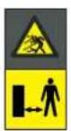
POZOR:
text_image
Diagram showing four types of waste management symbols: recycling, no litter, fire, and water discharge.

POZOR:
Pročitajte korisničke upute prije nego što pokrenete rad proizvoda.
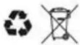
Bateriju nemojte odlagati kao običan otpad iz kućanstva.
Odložite bateriju u odgovarajućim ovlaštenim sabirnim centrima.

Nemojte bacati bateriju u vatru niti je izlagati izvorima topline.

text_image
Italian e Italian e German e Portuguese e French e Portuguese e Portuguese e French e Portuguese e Portuguese e French e Portuguese e Portuguese e French e Portuguese e Portuguese e French e Portuguese e Portuguese e French e Portuguese e Portuguese e French e Portuguese e Portuguese e French e Portuguese e French e Portuguese e Portuguese and Portuguese e French e Portuguese e Portuguese e French e Portuguese e Portuguese and Portuguese e French e Portuguese and Portuguese and Portuguese and Portuguese and Portuguese and Portuguese and Portuguese and Portuguese and Portuguese and Portuguese and Portuguese and Portuguese and Portuguese and Portuguese and Portuguese and Portuguese and Portuguese and Portuguese and Portuguese and Portuguese and Portuguese and Portuguese and Portuguese and Portuguese and Portuguese and Portuguese and Portuguese and Portuguese and Portuguese and Portuguese and Portuguese and Portuguese and Portuguese and Portuguese and Portuguese and Portuguese and Portuguese and Portuguese and Portuguese and Portuguese and Portuguese and Portuguese and Portuguese and Portuguese and Portuguese and Portuguese and Portuguese and Portuguese and Portuguese and Portuguese and Portuguese, respectively.
4. POSTAVLJANJE
4.1. OPĆE INFORMACIJE ZA POSTAVLJANJE

UPOZORENJE:
text_image
Diagram showing labeled components of a mechanical or electrical device, including an iron shaver, cable, and screw assembly.
4.3. PROVJERA ISPUNJAVANJA ZAHTJEVA ZA POSTAVLJANJE
text_image
Diagram illustrating a mechanical or electrical setup with labeled components A, B, C and measurement indicators x and x̄

POZOR:
text_image
Diagram showing a device mounted on a wall with a ruler and a mouse, labeled with dimension 'X' and figure marker (B)
4.3.3. GLAVNE PROVJERE ZA POSTAVLJANJE GRANIČNE ŽICE
text_image
Diagram illustrating plant growth in a pond with labeled points G and F, showing green plants and water levels.
4.4. KRITERIJI ZA POSTAVLJANJE GRANIČNE ŽICE
4.4.1. NAMJEŠTANJE GRANIČNE ŽICE
Postupak:
text_image
F
D
X3
F
E
X3
STIGA
text_image
O
P
M
x6
O
P
N
x6

UPOZORENJE:
flowchart
graph TD
    A["T"] --> B["Central Block"]
    B --> C["Right Block"]
    C --> D["Left Block"]
    D --> E["Central Block"]
    E --> F["Right Block"]
    F --> G["Left Block"]
    G --> H["Central Block"]
    H --> I["Right Block"]
    I --> J["Left Block"]
    J --> K["Central Block"]
    K --> L["Right Block"]
    L --> M["Left Block"]
    M --> N["Central Block"]
    N --> O["Right Block"]
    O --> P["Left Block"]
    P --> Q["Central Block"]
    Q --> R["Right Block"]
    R --> S["Left Block"]
    S --> T["Central Block"]
    T --> U["Right Block"]
    U --> V["Left Block"]
    V --> W["Central Block"]
    W --> X["Right Block"]
    X --> Y["Left Block"]
    Y --> Z["Central Block"]
    Z --> AA["Right Block"]
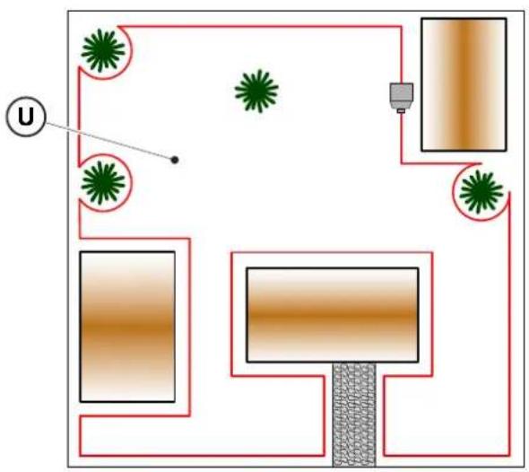
flowchart
graph TD
    A["Central Node"] --> B["Top Section"]
    B --> C["Left Side"]
    C --> D["Right Side"]
    D --> E["Bottom Section"]
    E --> F["Left Side"]
    F --> G["Right Side"]
    G --> H["Center Point U"]
    style A fill:#f9f,stroke:#333
    style B fill:#ccf,stroke:#333
    style C fill:#cfc,stroke:#333
    style D fill:#fcc,stroke:#333
    style E fill:#cff,stroke:#333
    style F fill:#ffc,stroke:#333
    style G fill:#fcf,stroke:#333
    style H fill:#cff,stroke:#333
natural_image
Illustration of a robotic vacuum cleaner and tree trunk with labeled parts (Z and V), no text or symbols present.
4.4.3. PROLAZI IZMEĐU RAZLIČITIH ZONA VRTA
Postupak:
- U slučaju prolaza, udaljenost između dvije različite sekcije granične žice mora biti Z ≥ 70 cm.
- U slučaju da je prolaz između dvije različite sekcije žice Z < 70 cm, zona (A) smatra se "Zatvoreno područje" i robotska kosilica ne može je automatski dostignuti.
text_image
A
R=20 cm

text_image
B
100 cm
text_image
Diagram illustrating the process of hairpin tool application, showing steps from pinning to cutting and holding a hairpin.
STIGA
- Pričvrstite bazu za punjenje (L) na teren pričvrsnim vijcima (M).
- Ponovno namjestite poklopac (C).
- Spojite konektor napajača na bazu za punjenje, zatim spojite utikač napajača u električnu utičnicu.
- Provjerite je li, kad robotska kosilica nije u bazi za punjenje, kontrolno svjetlo na bazi za punjenje (N) stalno upaljeno (vidi odl. 5.4)

POZOR:
text_image
Technical diagram of a mechanical assembly with labeled parts L, C, and M, showing screw installation and component layout.

natural_image
3D diagram of a mechanical device with a green indicator light and a magnified view showing internal components (no text or symbols)
NAPOMENA: Ako treba, kabel koji napaja bazu za punjenje možete produžiti pomoću produžnih kabela. Dopušta se uporaba najviše dvaju produžnih kabela od 5 metara (vidi pogl. 9 "Dodatna oprema").
4.5.4. POSTAVLJANJE OTPORNIKA ZA MALE PERIMETRE
Zahtjevi i obveze:
Dužina granične žice korištene za postavljanje robotske kosilice mora biti najmanje 40 metara. Ako je dužina žice manja, potrebno je postaviti otpornik (vidi pogl. 9 "Dodatna oprema"), serijski spojen u odnosu na graničnu žicu.
Postupak:
natural_image
Diagram of a red electrical fuse or terminal block with a circular symbol indicating the pin (no text or labels present)

text_image
D2
C
O
I
E2E2
4.6. PUNJENJE ROBOTSKE KOSILICE NAKON POSTAVLJANJA
Zahtjevi i obveze:
- Baza za punjenje.
Postupak:
- Napunite robotsku kosilicu (vidi odl. 5.5).
NAPOMENA: Prilikom prvog punjenja baterije se moraju puniti najmanje 2 sata.
©
POKAZATELJ POSTAVKI PROIZVODA
4.7.1. PRETPRIJAVA....31
4.7.2. REGISTRACIJA (SIGN UP) 31
4.7.3. UPARIVANJE (PAIRING) 31
4.7.4. STRANICA PROIZVODA (DEVICE PAGE) 32
4.7.5. ZATVORENO PODRUČJE (CLOSED AREA) 32