
Titan 540D - Lawn mower STIGA - Free user manual and instructions
Find the device manual for free Titan 540D STIGA in PDF.

| Product type | Self-propelled articulated 4x4 lawn mower |
| Brand | STIGA |
| Model | Titan 540D |
| Engine power | 17.4 kW (23.6 hp) |
| Fuel | Diesel (EN590:96) |
| Fuel tank volume | 42 liters |
| Maximum speed | 0 to 20 km/h |
| Weight | 714 kg |
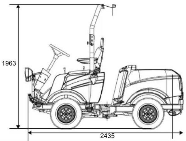
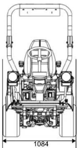
| Dimensions (L x W x H) | 2435 x 1084 x 1963 mm (roll bar raised) 1475 mm (roll bar lowered) |
| Drive | Hydraulic, four-wheel drive |
| Steering | Articulated power steering |
| Engine oil (type/volume) | CF or higher (CI-4 recommended) / 3.4 liters |
| Hydraulic oil (type/volume) | SAE 10W-30 (winter ISO VG 46) / 20 liters |
| Wheel motor oil (type/volume) | GL4/5 75W-90 / 4 x 0.08-0.09 liter |
| Operating ambient temperature | Down to -20 °C |
| Safety | Roll bar, seat belt, electrical safety with seat switch |
| Maintenance | Engine oil change every 200 h, air filter every 250 h, etc. |
| Compatible accessories | Cutting deck, spreader, etc. via front hydraulic PTO and auxiliary outlets |
| Lights | Yes (front light) |
| Trailer electrical socket | Yes (7-pin) |
| Hour meter | Yes |
Frequently Asked Questions - Titan 540D STIGA
User questions about Titan 540D STIGA
0 question about this device. Answer the ones you know or ask your own.
Ask a new question about this device
Download the instructions for your Lawn mower in PDF format for free! Find your manual Titan 540D - STIGA and take your electronic device back in hand. On this page are published all the documents necessary for the use of your device. Titan 540D by STIGA.
USER MANUAL Titan 540D STIGA
natural_image
Illustration of a small utility vehicle with front wheel, steering wheel, and driver seat (no text or symbols)BRUKSANVISNING SV .... 7
KÄYTTÖOHJEET FI.... 21
BRUGSANVISNING DA ... 35
BRUKSANVISNING NO... 49
flowchart
graph TD
    A["Force Input"] --> B["P"]
    B --> C["M"]
    C --> D["M"]
    D --> E["M"]
    E --> F["M"]
    F --> G["M"]
    G --> H["M"]
    H --> I["M"]
    I --> J["M"]
    J --> K["M"]
    K --> L["M"]
    L --> M["M"]
    M --> N["M"]
    N --> O["M"]
    O --> P["M"]
    P --> Q["M"]
    Q --> R["M"]
    R --> S["M"]
    S --> T["M"]
    T --> U["M"]
    U --> V["M"]
    V --> W["M"]
    W --> X["M"]
    X --> Y["M"]
    Y --> Z["M"]
    Z --> A
    style A fill:#f9f,stroke:#333
    style B fill:#ccf,stroke:#333
    style C fill:#cfc,stroke:#333
    style D fill:#fcc,stroke:#333
    style E fill:#cff,stroke:#333
    style F fill:#ffc,stroke:#333
    style G fill:#cfc,stroke:#333
    style H fill:#fcc,stroke:#333
    style I fill:#cfc,stroke:#333
    style J fill:#fcc,stroke:#333
    style K fill:#cfc,stroke:#333
    style L fill:#fcc,stroke:#333
    style M fill:#cfc,stroke:#333
    style N fill:#fcc,stroke:#333
    style O fill:#cfc,stroke:#333
    style P fill:#fcc,stroke:#333
    style Q fill:#cfc,stroke:#333
    style R fill:#fcc,stroke:#333
    style S fill:#cfc,stroke:#333
    style T fill:#fcc,stroke:#333

natural_image
Diagram of a device with labeled component B, showing internal structure and mounting points (no text or symbols beyond labels)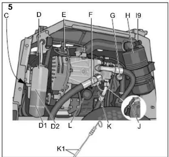
natural_image
Mechanical assembly diagram showing a spray gun pouring liquid into a vehicle (no text or symbols visible)20
21
natural_image
Technical line drawing of a mechanical assembly with dimension label (1084), no readable text or symbols present.1 ALLMÄNT

Justera ej ratten under körning.
Justera ej ratten under körning.
Justera ej ratten under körning.
7:H3 Inre luftfilter
6.13 ILMANSUODATIN, MOOTTORI

•Ved oppstilling. Parkeringsbrems.
- Redskap foran via hydraulikkuttaket (1:Aux2f).
6.8 SKIFTE HYDRAULIKKOLJE, FILTER
Ikke la det komme forurensning inn i hydraulikksystemet. Dette gir alvorlig skade på systemets komponenter.
6.10REMTRANSMISJONER
Kontroller etter 5 driftstimer at alle remmer er intakte og uskadde.
6.11RENGJ∅RING AV KJ∅LESYSTEMET
This symbol indicates CAUTION. Serious personal injury and/or damage to property may result if the instructions are not followed carefully.

You must read these instructions for use and the accompanying pamphlet "SAFETY INSTRUCTIONS" carefully, before starting up the machine.

Contaminants must not enter the hydraulic system or the fuel system. This causes serious damage to components of the systems.
1.1 SYMBOLS
The following symbols appear on the machine. They are there to remind you of the care and attention required during use and maintenance.
This is what the symbols mean:

Caution!
Read the instruction manual and the safety manual before using the machine.


Caution!
Watch out for discarded objects.
Keep onlookers away.

Caution!
Always wear hearing protectors.

Caution!
The machine, equipped with original accessories, must not be driven in any direction on slopes with a gradient greater than 10^ .

Caution!
Risk of crushing injuries. Keep all body parts away from the articulated steering when the engine is running.

Caution!
Risk of burn injuries. Do not touch the silencer/catalytic converter.

Caution!
Before starting repair work, remove the ignition key from the machine.
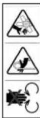
Caution! Risk of crushing injuries, rotating fan.
Risk of crushing injuries, rotating belt.
Risk of crushing injuries, mechanical parts.
1.2 REFERENCES
1.2.1 Figures
The figures in these instructions for use are numbered 1, 2, 3, etc.
Components shown in the figures are marked A, B, C, etc.
A reference to component C in figure 2 is written "1:C".
1.2.2 Headings
The headings in these instructions for use are numbered in accordance with the following example:
“1.3.1 General safety checks” is a subheading to “1.3 Safety checks” and is included under this heading.
When referring to headings, only the number of the heading is normally specified. E.g. "See 1.3.1".
2 TECHNICAL DATA
2.1 MACHINE DATA
| 540 740 | ||
| Engine output, kW 17. | 4 22.2 | |
| Drive PTO Hydraulics | ||
| Speed, km/h 0-20 0-20 | ||
| Weight, kg 714 731 | ||
| Height, mm 1963/1475* | ||
| Length, mm 2435 | ||
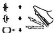
| Width, mm 1084 | ||
| Engine oil, volume 3.4 litres 3.6 litres | ||
| Engine oil, grade | See 5.3 | |
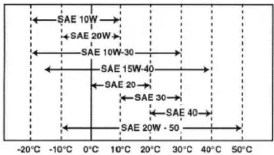
| Hydraulic oil | 20 litres SAE 10W-30When using in winter ISO VG 46. See 2.2.1 | |
| Oil wheel motors | 4x0.08-0.09 litres GL4/5 75W-90 | |
| Ambient temperature | Down to -20°C. | |
| Fuel | Diesel (EN590:96) | |
| Tank volume | 42 litres | |
*With protective fram folded down
2.2 HYDRAULIC - OVERVIEW
The table below gives an overview of the hydraulic outputs and their controls.
| Abbreviation | Meaning Dimensions Capacity* | ||
| PTO Output for driving front mounted implements. See fig. 1. | 2x1/2” + 3/8” return | 42 l / 220 bar | |
| PTOs Control for operation of output for driving implements. See fig. 1. | |||
| Aux1 Output for auxiliary functions on front mounted implements. See fig. 1. | 2x1/4” 12l / 125 bar | ||
| Aux1s Control for operating the Aux1. See fig. 1. | |||
| Aux2f | Output for auxiliary functions on front mounted implements. See fig. 1. | 2x1/4” 12l / 125 bar | |
| Aux2r (740) | Output for auxiliary functions on rear mounted implements. See fig. 1. | 2x1/4” 12l / 125 bar | |
| Aux2S | Control for operating the Aux2f and Aux2r depending on Aux2fr See fig. 1. | ||
| Aux2fr (740) | Control for activating Aux2f or Aux2r. See fig. 1. | ||
| L | Tool lift See fig. 1. | ||
| Ls | Control for operating the tool lift and lifting tools is mounted under the cab. See fig. 1. | ||
2.2.1 Hydraulic oil
SAE 10W-30 is recommended.
When using in winter an ISO VG 46 oil can be used. This oil can also replace SAE 10W-30 if the hydraulic response is slow.
2.3 IMPLEMENTS
For implements, contact an authorised dealer and read the instructions for use supplied with the accessory.
3 DESCRIPTION
3.1 DRIVE
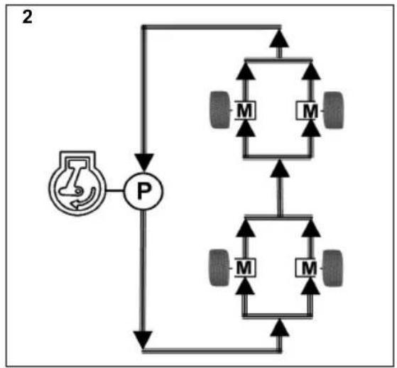
The machine is four wheel drive. The power from the engine to the driven wheels is transferred hydraulically. The four wheels are equipped with separate hydraulic motors. The diesel motor drives a hydraulic pump (2:P), which pumps oil through the hydraulic motors (2:M) of the wheels.
The hydraulic motors are connected to the hydraulic pump according to fig. 2.
This means that the front and rear wheels are forced to rotate at the same speed, but the speed on the right and left side can vary.
3.2 STEERING

Keep all body parts away from the machine's pivot point when the steering wheel is turned. There is a risk of serious crushing injury between the machine's rear and front sections.
The machine has articulated steering, which is power assisted. This means that the chassis is divided into a front and rear section, which can be turned in relation to each other.
The articulated steering means that the machine has an extremely small turning circle and can be easily tuned around trees and other obstacles.
3.3 SAFETY
3.3.1 Electric safety system
The machine is equipped with an electric safety system. The safety system stops certain activities that may be hazardous in the event of incorrect operation. E.g. The engine cannot be started if the clutch pedal/parking brake is not depressed.

The safety system's function must always be checked before use.
3.3.2 Warning triangle
There is a warning triangle delivered with the machine. This must be placed on the road in an emergency situation in accordance with local regulations.

Check that the warning triangle is always taken when travelling.
3.3.3 Safety belt (1:G)
Aways use the safety belt when driving the machine.
3.3.4 Protective frame (1:N)
The machine is equipped with a protective frame.

Always drive with the protective frame in upright position. Only fold the frame when driving on a level surface and the frame has to be folded for the machine to be able to pass
3.4 CONTROLS
The descriptions of the controls are gathered by how they are placed in the machine.
Controls - seat
See 3.4.1
Controls – steering bracket and pedals
See 3.4.2
Controls – instrument panel
See 3.4.3
Controls - other
See 3.4.4
3.4.1 Controls - seat
The seat is equipped with a safety switch that is connected to the machine's safety system. This means that certain dangerous activities are not possible when there is nobody sitting on the seat. See also 5.7.2.
3.4.1.1 Adjusting seat backwards/forwards (1:A1)
- Move the control lever (1:AJ) upwards.
- Set the seat to the desired position.
- Release the control lever to lock the seat.
3.4.1.2 Adjusting seat suspension (1:A2)
The suspension of the seat can be adjusted according to body weight using the knob.
Harder suspension: Turn the knob clockwise.
Softer suspension: Turn the knob anticlockwise.
The suspension setting can be read off from the indicator (1:J2) by the knob. At correct setting the indicator shows green.
3.4.1.3 Adjusting the backrest angle (1:A3)
The backrest can be adjusted to the desired angle using the knob.
3.4.1.4 Adjusting the armrest (1:A4)
The armrest can be adjusted to the desired angle using the knob under the relevant armrest.
3.4.1.5 Storage compartment (1:F)
A storage compartment is located under the seat.
3.4.2 Controls – steering bracket and pedals
3.4.2.1 Steering wheel (1:B1)

Do not adjust the steering wheel during operation.
The steering wheel can be raised and lowered and set at different angles smoothly. See 3.4.2.5 and 3.4.2.2.
3.4.2.2 Adjusting steering wheel height (1:B2)

Do not adjust the steering wheel during operation.
The height of the steering wheel is steplessly adjustable.
Undo the knob on the steering column and raise or lower the steering wheel to the desired position.
Tighten.
3.4.2.3 Headlight (1:B3)
Pull the switch to activate the headlight (1:H).
Push down to turn headlight off.
3.4.2.4 Adjusting steering wheel angle (1:B4)

Do not adjust the steering wheel during operation.
The steering wheel can be set at different angles steplessly
Release the control on the side of the steering column and set the steering wheel to the desired angle. Tighten the control.
3.4.2.5 Drive / service brake (1:B5)

If rapid deceleration becomes necessary the pedal should be reversed sharply. NOTE! This makes the operator affected by powerful forces.

Never press the drive pedal when parking brake is activated. This puts unnormal load on the parking brake and shortens its service life.
The pedal determines the gear ratio between the engine and the driven wheels (= speed). The service brake is activated when the pedal is released or pressed towards neutral position.
EN
ENGLISH
- Press the pedal forwards- the machine starts to move for- wards.
- No load on the pedal – the machine is stationary.
- Pedal moved backwards – the machine reverses.
4 The pedal is pressed towards neutral position - the machine breaks.

In case of an emergency and the machine does not brake as expected when the pedal is reversed, the left pedal (1:B6) should be used as an emergency brake. NOTE! This puts unnormal load on the parking brake and shortens its service life.
3.4.2.6 Parking brake / Emergency brake (1:B6)

Never press the pedal while driving except for in an emergency. Pressing the pedal while driving reduces the service life of the parking brake wich results in a loss of functionality.
The pedal has the following functions:
- When stopping. Parking brake.
•During operation. Emergency brake.
Indicator (1:13) lights when the pedal is completely depressed.
3.4.2.7 Inhibitor, parking brake (1:B7)

Never press the drive pedal (1:B5) when parking brake is activated. This puts unnormal load on the parking brake and shortens its service life.

The inhibitor locks the pedal (1:B6) in the depressed position. The function is used to lock the machine on slopes, when transporting, etc. when the engine is not running.
Locking:
- Depress the pedal (1:B6) fully. The indicator (1:I3) lights.
- Press the inhibitor
- Release the pedal.
Releasing:
- Depress the pedal (1:B6) fully.
- Release the pedal.
3.4.3 Controls – instrument panel
3.4.3.1 Throttle control (1:D1).
Control for setting the engine's revs.
Front position - Full throttle - when the machine is in operation, full throttle should always be used.
Rear position - Idling.
3.4.3.2 Ignition lock (1:D2)
The ignition lock is used for starting and stopping the engine.
Four positions:

Preheat position: The cylinders are heated to facilitate starting. Hold in this position as below at lower temperatures before starting the engine.
Max 5 seconds

Stop position: The engine is stopped. The key can be removed.

Operating position: Bypassed at start-up and used when the engine is running.

Start position: The electric starter motor is activated when the key is turned to the spring-loaded starting position. Once the engine has started, let the key return to the operating position.
3.4.3.3 Implement lifter (1: Ls)
This control controls both the hydraulic tool lift at the front of the machine (1:L) and the lift cylinder for tools installed under the cab. These are connected in series.
The control (1:Ls) only works when the engine is running.
However, it can be lowered to the floating position when the engine is off.

Never leave the machine with the implement in the transport position. Risk of serious crushing injuries by the implement as it lowers quickly if the control is unintentionally affected.
The lever has the four following positions:

Floating position. Move the lever to its front position, where it locks. The implement is now lowered to its floating position.
In the floating position, the implement always rests against the ground at the same pressure and can follow the contours of the ground.
Use the floating position when carrying out work.

Lowering. The implement lowers regardless of its weight. The lowering force is determined by the implement's weight and the hydraulic down force that is applied when lowering.

Locking in the transport position. The lever has returned to the neutral position after raising and lowering. The implement is locked in the transport position.

Raising. Move the lever to the rear position until the implement is in the highest position (transport position). Then release the lever to lock in the transport position.
3.4.3.4 Hydraulic control (1:Aux1s)
This control is used to control certain functions depending on the attached implement.
The control only works when the engine is running and the implement's hydraulic hoses for the intended function are connected to the hydraulic output (1:Aux1).
3.4.3.5 Hydraulic control (1:Aux2s)
This control is used to control certain functions depending on the attached implement.
The control only works when the engine is running and the implement's hydraulic hoses for the intended function are connected as follows:
- Implement at the front via the hydraulic outputs (1:Aux2f).
- 740: Implement at the rear via the hydraulic output (1:Aux2r). See also 3.4.3.9
Both hydraulic outputs on the rear section are connected in parallel.
3.4.3.6 Switch (1:Os)

The switch can be used to smoothly set the cutting height of the cutting deck with electric cutting height adjustment. The switch controls the contact (10) with switching polarity.
3.4.3.7 Switch (1:PTOs)
A lever for engaging and disengaging the operation of the front mounted implement. Two positions:

- Press the front part of the switch – PTO engages. The symbol will light up.
- Press the rear part of the switch – PTO disengages.
To prevent unnecessary increases in pressure in the hydraulic system, set the throttle control to 1/4 throttle before the hydraulic PTO is engaged.
The control activates a valve that transfers the power from the hydraulic pump to the front mounted implement.
The power is then transferred hydraulically to the tool via the hydraulic output at the front (1:PTO).
3.4.3.8 Switch (1:Ts)
12V The switch has three positions and can be used for the sand spreader for example.
The switch controls the contact (1:T).
3.4.3.9 Switch (1:Aux2fr) (740)

The switch has two positions and indicates which hydraulic output will be activated by the control (1:Aux2s). Front mounted
hydraulic output (1:Aux2f) or rear mounted hydraulic output (1:Aux2r). See also 3.4.3.5
3.4.4 Controls - other
3.4.4.1 Locking pins front (1:C1)
The machine has front and rear sockets for different implements. The relevant implement is locked by two locking pins after installation.
To secure the implement on the implement lift:
-
Insert the locking pin fully from the outside.
-
Place your foot on the locking pin and turn backwards until it locks.

Do not turn the locking pin using your hands. Risk of crushing injuries.
To release:
- Turn the locking pin forwards until it unlocks.
- Pull out the locking pin.
3.4.4.2 Locking pins rear(1:E1)
The machine has front and rear sockets for different implements. The relevant implement is locked by two locking pins after installation. The rear locking pins self-lock in their grooves after installation.
3.4.4.3 Main switch (1:E2)

Before carrying out work on the electrical system, the power must be cut using the main switch.
3.4.4.4 Engine casing

The machine may not be operated unless the engine casing is closed and locked. Risk of burns and crushing injuries.
To access components on the engine, there are four detachable covers. Open the covers as follows:
Cover on the right and left sides (1:K)
Removing:
- Remove the front and rear rubber straps (1:J).
- Pull the cover upward, fold it down and pull it out.
Installing:
- Lower the cover over the inside of the wheel.
- Hook the cover's upper part into the machine's V-groove and insert the locating pin at the bottom.
- Hook on the front and rear rubber straps.
Front cover (1:R)
Removing:
- Remove the two front rubber straps.
- Open the locking knobs (4:B).
- Move the cover forward and upward.
Installing:
- Align the cover.
- Insert the locking knob lugs in the holes on top and close the locking knobs.
- Hook on the two rubber straps.
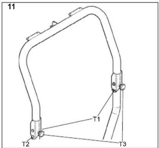
3.4.4.5 Protective frame (1:N)

Always drive with the protective frame in upright position. Only fold the frame when driving on a level surface and the frame has to be folded for the machine to be able to pass
Folding backwards:
- Remove the hairpin (11:T1) and the pin (11:T2).
- Fold the frame backwards.
- Reinsert the pin and lock in place with hairpin for safekeeping
Unfold to upright position:
- Remove the hairpin and the pin.
- Unfold the frame to upright position
- Lock the frame in upright position by inserting the pin and the hairpin.
- Thighten the knob (11:T3) until there is no slack
3.4.4.6 Electrical socket for trailer (1:R)
Seven-pin socket for trailer.
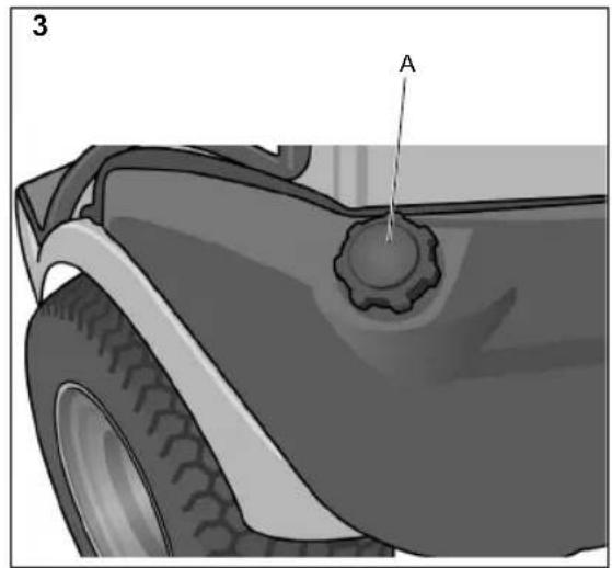
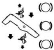
3.4.4.7 Fuel cap (3:A)
The fuel cap for filling diesel is located behind the seat.
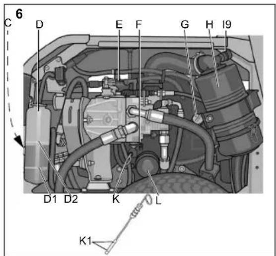
3.4.4.8 Disengagement lever (5, 6:F)
A lever for disengaging the variable transmission. Enables the machine to be moved.

The disengagement lever must never be between the outer and inner positions. This overheats and damages the transmission.

The machine must never be towed but may only be moved to and from a trailer, if necessary. Towing damages the transmission.
The lever has the following two positions:
Lever inwards:
The hydraulic pump is engaged for normal use.
Lever outwards:
The hydraulic oil is connected passed the hydraulic pump and can flow around the system without the hydraulic pump blocking the flow. The machine can be moved. The flow is restricted, however, and is why relatively large force is required to move the machine.
3.4.4.9 Hand pump (5:J) (540)
If the diesel pump has drawn in air, e.g. after running out of fuel, the engine is unable to draw in new fuel itself. Fuel must, therefore, be pumped in using the hand pump before attempting to start.
3.5 INDICATORS
3.5.1 Fuel gauge (1:I1)
The fuel gauge indicates the level of the fuel in the fuel tank.
3.5.2 Indicator for seat suspension (1:12)
Shows the seat suspension setting. See 3.4.1.2.
3.5.3 Brake indicator (1:13)
Never operate the machine with the brake indicator illuminated. Parking brake and emergency brake will be affected.

The brake indicator gives a warning that the parking brake (1:B6) is activated. See 3.4.2.6.
3.5.4 Battery charging indicator (1:14)
Never run the engine with the charging indicator illuminated. This will drain the battery.

The battery charging indicator is only activated when the ignition is in the operating position.
The battery charging indicator gives a warning when the engine's alternator stops charging the battery. When the engine is not running the indicator should illuminate as the alternator does not generate any charge.
When the engine is running the indicator should not be illuminated. If the indicator illuminates during operation, the battery discharges and the engine cannot be started. Take the machine to an authorised workshop for repair.
3.5.5 Hydraulic oil temperature indicator (1:15)

The engine must never be run when the temperature indicator is illuminated. Risk of serious engine damage.

The hydraulic oil temperature indicator is only activated when the ignition is in the operating position.
The hydraulic oil temperature indicator gives a warning when the hydraulic oil temperature exceeds a harmful level.
When the engine is running the indicator should not be illuminated. If the indicator illuminates during operation, carry out the following:
- Set the throttle control to idle. Do not stop the engine.
- Clean away any leaves, grass or any other objects from the outside of the oil cooler. See 5.12.
- Leave the engine idling until the temperature has dropped, the indicator has gone out. The machine can then be used as normal.
- If the temperature has not dropped within 5 minutes, stop the engine and take the machine to an authorised workshop for repair.
3.5.6 Engine temperature indicator (1:16)
Too high engine temperature is indicated partly by the indicator and partly by a buzzer that sounds.

The engine must never be loaded or operated at more than idle speed with the temperature indicator illuminated or when the buzzer sounds. Risk of serious engine damage.

The engine temperature indicator and buzzer are only activated when the ignition is in the operating position.
The engine temperature indicator and buzzer give a warning when the engine temperature exceeds a harmful level.
When the engine is running the indicator should not be illuminated and the buzzer should not sound. If the indicator illuminates or if the buzzer sounds during operation, carry out the following:
- Set the throttle control to idle. Do not stop the engine.
- Clean away any leaves, grass or any other objects from the outside of the radiator. See 5.12.
- Leave the engine idling until the temperature has dropped, the indicator has gone out and the buzzer stopped. The machine can then be used as normal.
- If the temperature has not dropped within 5 minutes, stop the engine and take the machine to an authorised workshop for repair.
In the event of an indication of too high engine temperature, check the coolant level. See 5.4.
3.5.7 Oil pressure indicator (1:17)

The engine must never be run when the oil pressure indicator is illuminated. Risk of serious engine damage.

The oil pressure indicator is only activated when the ignition is in the operating position.
The oil pressure indicator gives a warning when the engine oil pressure falls below a harmful level. When the engine is not running the indicator should illuminate as there is no oil pressure.
When the engine is running the indicator should not be illuminated. If the indicator illuminates during operation, stop the engine immediately and take the machine to an authorised workshop for repair.
3.5.8 Hour meter engine (1:18)
Indicates the number of working hours. Only works when the engine is running.
3.5.9 Air filter indicator (5,6:19)
The indicator warns of a blocked air filter. If the indicator is red, the air filter must be replaced. Then reset the indicator by pressing its button.
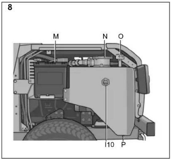
3.5.10 Hydraulic oil level indicator (8:110)
The oil level must be visible through the transparent glass when the machine is level.
If the oil level is too high there is a risk of oil flowing out through the bleed valve. If the oil level is too low there is a risk of an increase in the oil temperature and damage to the hydraulic system.
4 AREAS OF USE
The machine may only be used together with original accessories.
Optional kits are available for the machine that contain the equipment required in order to drive on public roads. The contents of the kits are adapted according to local regulations. Contact an authorised dealer for purchase information and purchase.
The machine may not be operated unless the engine casing is closed and locked. Risk of burns and crushing injuries.

Ensure no one is near the pivot point of the machine when the engine is running. There is a risk of serious crushing injury between the machine's rear and front sections.

Depending on the implement used, counter weights might have to be mounted on the machine. The axle pressure of a wheel axle may never exceed 900 kg or 70% of the total weight of the machine
5.1 ACTIONS BEFORE STARTING
Carry out the following before starting the machine:
- Check/top up with fuel.
- Check the engine oil level.
EN
ENGLISH
- Check the coolant level.
- Check to make sure that the air filter indicator has not been tripped.
- Check that the water separator's and fuel filter's taps are open.
- Check that the water separator does not contain water. Drain if necessary.
- Check the oil level in the hydraulic tank. See 3.5.10.
- Carry out safety checks.
- Check that the disengagement lever is in the inner position. See 3.4.4.8.
The above actions are described below.
5.2 REFUELLING

Diesel is highly inflammable. Always store fuel in containers that are made especially for this purpose.

Only fill or top up with fuel outdoors, and never smoke when filling or topping up. Fill up with fuel before starting the engine.
Never remove the fuel cap or fill with fuel while the engine is running or still warm.

The engine must not be run on rapeseed diesel (RME). Contact the engine supplier for additional information.

Filling fuel up into the filler pipe results in fuel leakage and risk of fire.
Only use diesel which satisfies the requirements in 2.1.
- Open the fuel cap (3:A).
- Fill with diesel up to the lower part of the filler pipe. If fuel is filled up into the filler pipe, fuel will leak out because it expands when heated.
- Close the fuel cap.
5.3 LEVEL CHECK, ENGINE OIL
Check the oil level every time before using to ensure it is correct. The machine should be standing on level ground.
Check the following:
- Wipe clean around the oil dipstick (5, 6:K), and pull it up.
- Wipe the dipstick.
- Slide the dipstick down completely and pull up again.
- Read off the oil level. The oil level should be within the markings (5, 6:K1) on the dipstick.
If necessary, remove the oil filler cap (5, 6:G) and fill up the oil up to the mark.
Use oil grade API CF or higher, but not CG, C1-4 is recommended, and according to the temperature diagram below.
Never use oil additives.
The oil level must never go below the lower marking. This can cause the engine to overheat. Drain the oil to the correct level if the oil level exceeds the mark. See 6.7.
Reinstall the oil filer cap once the oil level has been adjusted.
5.4 LEVEL CHECK, COOLANT

The temperature indicator will not work if there is no coolant. This results in engine failure.
Check the coolant level every time before use to ensure it is correct.
Check the following:
- The engine must be cold when checking.
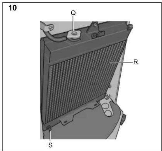
- Remove the front engine cover. See 3.4.4.4.
- Unscrew the radiator cap (10:Q) and check that the coolant level reach the filler hole.
- Reinstall the radiator cap.
- Check that the coolant level is at the lower mark (5, 6:D1) in the expansion tank. If necessary, top up with coolant. See below.
5.4.1 Topping up with coolant
The coolant must meet the following requirements:
• Always use a mixture of refrigerant and water. Never use just water.
- Mix the water and refrigerant according to the refrigerant supplier's instructions.
- Never mix different refrigerants.
- Use soft water (no calcium content), distilled or demineralised water.
The engine must be cold when filling.

If the radiator cap is opened when the engine is hot there is a risk of serious burn injuries from hot water that may spray out.
Top up as follows:
- Remove the front engine cover.
-
Check that all the plugs in the cooling system are installed and sealed.
. Check that all the taps in the cooling system are closed and sealed. -
Check that all the hoses in the cooling system are intact and sealed.
- Unscrew the radiator cap (10:Q).
- Slowly fill the radiator with coolant. Air bubbles must not form when filling. Fill up to the filler hole.
- Reinstall the radiator cap.
- Open the cap on the expansion tank (5, 6:D) and top up the mixture to the lower mark which is the level when the engine is cold.
- Close the cap for the expansion tank.
- Run the engine to operating temperature and check the level in the expansion tank. The level should now be at the upper mark (5, 6:D2), which is the level for when the engine is hot.
- If the level is not up to the upper mark, allow the engine to cool and then top up with coolant in the expansion tank.
5.5 AIR FILTER INDICATOR
Check to make sure that the air filter indicator (5, 6:I9) has not been tripped.
Check, see 3.5.9.
Replace the air filter, see 6.13.
5.6 WATER SEPARATOR
Check that the water separator's float (12, 13:C3) is at the bottom.
Check that the water separator's tap is open. See fig. 10.
5.7 SAFETY CHECKS
Check that the results of the safety checks below are met when testing the machine.

The safety checks must always be carried out before use.
If any of the results below are not met, the machine must not be used! Take the machine to a service workshop for repair.
5.7.1 General safety checks
| Object Result | |
| Fuel lines and connections. | No leak. |
| Power cables. All | insulation intact.No mechanical damage. |
| Exhaust system. No | leakage in the connections.All screws tightened. |
| Hydraulic hoses. No | leakage. No damage. |
| Drive the machine forwards/backwards and release the drive/service brake pedal. | The machine should stop. |
| Test driving. No | unusual vibrations.No unusual noise. |
5.7.2 Electric safety check

The safety system's function must always be checked before use.
| Status | Action | Result |
| The clutch-brake pedal not depressed. PTO not activated. | Attempt to start. | The engine should not start. |
| The clutch-brake pedal not depressed. PTO activated. | Attempt to start. | The engine should not start. |
| Engine running. PTO activated. | The operator leaves the seat. | PTO should disengage. |
| Control for implement lifter not in floating position. | Attempt to engage PTO. | PTO should not be able to be engaged. |
5.8 START
- Check that PTO is disengaged.
- Do not keep your foot on the accelerator pedal.
- Set the throttle control to 14 throttle.
- Depress the brake pedal fully. The indicator lamp (1:I3) should illuminate.
- For cold starts at lower temperatures, the engine should be preheated before starting. See 3.4.3.2. Then return the ignition key and start the engine.
- The machine must never be loaded or driven directly after a cold start when the hydraulic oil is cold.
Heat the hydraulic oil by running the engine at 14 throttle. Run it for a few minutes as shown in the diagram below..
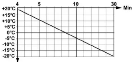
line
| Time (Min) | Temperature (°C) | |---|---| | 4 | +20 | | 5 | +15 | | 10 | +10 | | 30 | -20 |Temp °C
Example: At -10^ run at 14 throttle for 18 minutes.
When the machine is in operation, full throttle should always be used.
To prevent unnecessary increases in pressure in the hydraulic system, set the throttle control to 1/4 throttle before the hydraulic PTO is engaged.
5.9 POWER ASSISTED STEERING
The power steering transfers the force from the machine's hydraulic system to the steering wheel when turned. This makes the machine very easy to steer when the engine is running at full throttle.
Power steering forces reduce as the engine speed reduces.
5.10 OPERATING TIPS
Always ensure that the correct amount of oil is in the engine. Especially when driving on slopes. See 5.3.

Be careful when driving on slopes. No sudden starting or stopping when moving up or down a slope. Never drive across a slope. Move from the top down, or from the bottom to the top.

The machine must not be driven in any direction on slopes with a gradient greater than 10^ .

Reduce the speed on slopes and when making sharp turns to prevent the machine from tipping over or you losing control.

Do not turn the steering wheel to full lock when driving in top gear and at full throttle. The machine can easily topple over.

Keep hands and fingers well away from the articulated steering joint and seat bracket. Risk of crushing injuries. Never drive with the engine casing open.

Depending on the implement used, counter weights might have to be mounted on the machine. The axle pressure of a wheel axle may never exceed 900 kg or 70% of the total weight of the machine
5.11 STOP
Disengage PTO. Apply the parking brake.
Allow the engine to idle 1 - 2 mins. Stop the engine by turning off the starter key.

If the machine is left unattended, remove the ignition key.

The engine may be very hot immediately after it is shut off. Do not touch the silencer or other engine parts. This can cause burn injuries.
5.12 BLEEDING THE FUEL SYSTEM (540)
If there is air in the fuel system, this must be bled manually. Air may have entered due to the following:
• After stopping due to lack of fuel.
• After replacing the filter.
• After draining the water separator.
• After carrying out repairs in the fuel system.

Never attempt to carry out bleeding by turning the engine with the starter motor. This will damage the starter motor.
Bleed as follows:
- Check that the fuel tank is filled.
- Open all taps in the fuel system.
- Pump using the control (5:J) until all air has been pumped out of the fuel system.
- Attempt to start. If the engine does not start, continue bleeding as above.
5.13 CLEANING

To reduce the risk of fire, keep the engine, silencer, battery and fuel tank free from grass, leaves and oil.

To reduce the risk of fire, regularly check the machine for oil and/or fuel leakage.

Never use high-pressure water. This can damage shaft seals, electrical components or hydraulic valves.

Never use high-pressure air against the radiator fins. This will damage the fin structure.
Clean the machine after use. The following instructions apply to cleaning:
- Do not point jets of water directly at the engine.
- Clean the engine with a brush and/or compressed air.
- Clean the engine's radiator (10:R) with a soft brush. Large objects can be removed by hand. If the coolers are heavily soiled, clean using slow running water and a suitable detergent.
• After cleaning with water, start the machine and any cutting deck to remove the water that may otherwise penetrate bearings and cause damage.
6 MAINTENANCE
6.1 SERVICE PROGRAM
In order to keep the machine in good condition, as regards reliability and operational safety as well as from an environmental perspective, the service instructions in this section should be followed.
All services should be carried out by authorised workshops.
Service, carried out by authorised workshops, guarantees a professional job with original replacement parts.
The service log should be stamped at every service carried out by an authorised workshop. A “fully
stamped" service log is a valuable document that improves the machine's second-hand value.
The service points are given in the table below. Descriptions of how the procedures are to be carried out are given after the table.
6.2 SERVICE POINTS.
| Service point | 1st time | Interval See | Para-graph |
| Hours of operation/ Calendar months | |||
| Water separator, check | 50/- 6.4 | ||
| Pre-filter, cleaning 6 | 4 | ||
| Fuel filter, replace 4 | 00/- 6.5 | ||
| Tyre pressure, check, adjust | 6.6 | ||
| Engine oil, filter, change | 50/12 20 | 00/12 6.7 | |
| Hydraulic oil, filter, tank vent valve, change/clean | 50/12 40 | 00/12 6.8 | |
| Wheel motors, change oil | 50/12 20 | 00/12 6.9 | |
| Belt transmissions, check | 50 200/- 6.10 | ||
| Cooling system, clean | 1000/12 | 6.11 | |
| Battery, check | 50/- 6.12 | ||
| Air filter, clean pre-filter | 250/- 6.13 | ||
| Air filter, change inner filter | 250/- 6.13 | ||
| Lubrication | 6.14 | ||
| Adjusting valves | 1000/- | 6.15 | |
| Grinding valves | 2000/- | 6.15 | |
6.3 PREPARATION
All service and all maintenance must be carried out on a stationary machine with the engine switched off.

Prevent the machine from rolling by always applying the parking brake.
Stop the engine.
Prevent unintentional starting of the engine by removing the ignition key.
6.4 WATER SEPARATOR
There is a float in the water separator (12, 13:C3) that can be viewed through the transparent cup. The float must be at the bottom. If the float has risen, the water separator must be drained as follows:
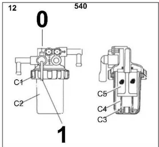
6.4.1 540
- Shut off the water separator tap. See fig. 12.
- Hold a container under the water separator to collect fuel.
- Open the cup by pressing its ring (12:C1).
- Carefully remove the cup (12:C2) and remove the spring, (12:C4) and float (12:C3) from the cup.
- Clean the inside of the cup and thread filter (12:C5).
- Check that the O-ring is intact and reinstall the components in reverse order.
- Open the tap.
Clean the fuel tank if water accumulates in the water separator often. Contact an authorised workshop.
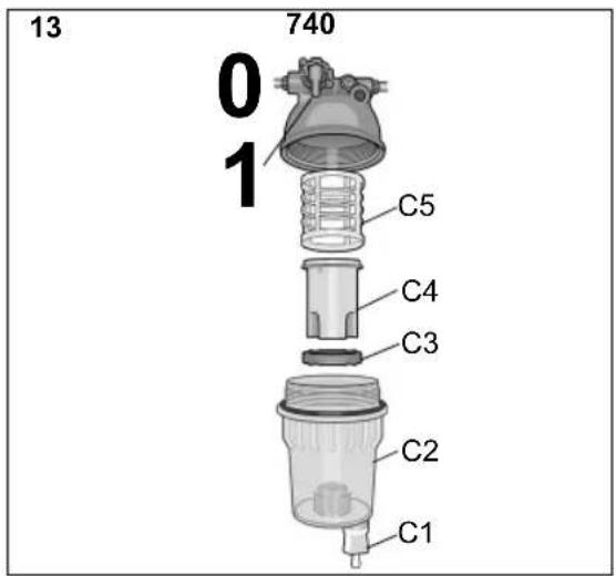
6.4.2 740
To drain the water unscrew the drain tap (13:C1) until the water begins to run. Drain until the float sits at the bottom again.
Clean the separator if the it looks dirty or if it has to be drained often. The separator is cleaned as follows:
- Shut off the water separator tap. See fig. 13.
- Hold a container under the water separator to collect fuel.
- Unscrew the cup. (13:C2).
- Carefully remove the cup and remove the thread filter (13:C5), the insert (13:C4), and the float (13:C3) from the cup.
- Clean the inside of the cup and thread filter.
- Check that the O-ring is intact and reinstall the components in reverse order.
- Open the tap.
Clean the fuel tank if water still often accumulates in the water separator. Contact an authorised workshop.
6.5 FUEL FILTER
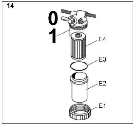
6.5.1 540
- Shut off the fuel filter's tap. See fig. 14.
- Hold a container under the fuel filter to collect fuel.
- Detach the cup by turning its ring (14:E1).
- Carefully remove the cup (14:E2) and remove the filter (14:E4).
- Clean the inside of the cup.
- Check that the O-ring (14:E3) is intact and reinstall the components with new filter in reverse order.
- Open the tap.
- Bleed the fuel system. See 5.12.
EN
ENGLISH
6.5.2 740
- Stop the engine and allow it to cool.
- Close all the fuel taps.
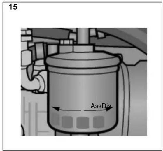
- Use an oil filter wrench to slacken off the filter (6:E) in the direction (15:Dis). Carefully remove the filter to prevent the spillage of fuel. Wipe up any spilled fuel.
- Clean around the mounting surface of the filter.
- Apply a thin layer of fuel to the new filter gasket.
- Install the new filter by rotating it in the direction (6:Ass) until the gasket comes into contact with the mounting surface.
- Then tighten the filter a further turn using the filter wrench.
6.6 TYRE PRESSURE
Pressure front and back: 0.9 bar.
See pressures in the manual for relevant implement.
6.7 CHANGING ENGINE OIL, FILTER

The engine oil may be very hot if it is drained off directly after the engine is shut off. So allow the engine to cool a few minutes before draining the oil.
Change engine oil and filter as follows:
- Place the machine on a level surface and run the engine to operating temperature.
- Stop the engine and remove the oil filler cap (5, 6:G).
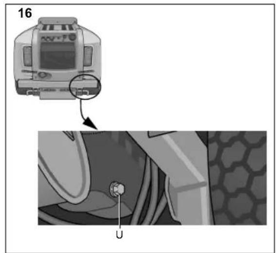
- Place a container under the oil drain plug (16:U), remove the plug and let the oil run out into a container.
- Dispose of the oil according to local regulations.
- Clean the area around the oil filter (5, 6:L) and remove the filter. Use an oil filter wrench.
- Lubricate the gasket on the new filter and screw this in until the gasket touches the surface of the engine. Then tighten the filter a further turn using an oil filter wrench.
- Install the oil drain plug. Tighten to 50 Nm.
- Fill with new oil according to 5.3.
- After filling the oil, start the engine and run at idle speed for 30 seconds.
- Check to see if there is any oil leakage.
- Stop the engine. Wait for 30 seconds and then check the oil level. See 5.3.
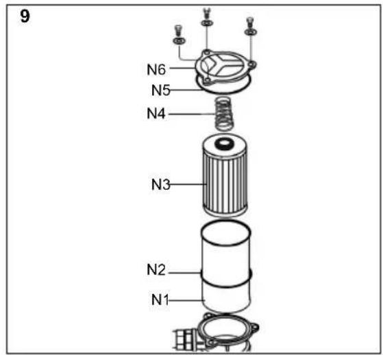
6.8 CHANGING HYDRAULIC OIL, FILTER

No contaminants must enter the hydraulic system. This causes serious damage to components of the systems.
Change hydraulic oil and filter as follows:
- Operate the machine at varying workload for 5-10 minutes in order to warm up the hydraulic oil.
- Place the machine on a level surface.
- Clean the area around the filter (8:N) thoroughly on the upper part of the hydraulic tank and remove the filter cup and the filter.
- Place a container under the oil drain plug (8:P), remove the plug and let the oil run out into a container. The container must have a capacity of 20 litres.
- Dispose of the oil according to local regulations.
- Install the oil drain plug. Tighten to 25 Nm.
- Replace the tank vent valve (8:O). The valve is unscrewed and the new one is installed in reverse order.
- Reinstall the filter with the following components:
9:N1Filter cup. Clean the filter cup thorough before reinstalling.
9:N2 Gasket. Check that the washer is intact.
9:N3New filter. The filter must always be replaced when changing the oil.
9:N4Spring
9:N5 Gasket. Check that the washer is intact.
9:N6Cover - Fill with new oil through the 3/8" return for PTO, see fig. 1. Use a pump with 10 micron filter.
Oil: See 2.1.
Oil quantity when changing: See 2.1. - After filling the oil, start the engine and run the machine for a few minutes and check for oil leakage.
- Check the oil level. See 3.5.10.
6.9 CHANGING THE OIL IN THE WHEEL MOTORS
Change the oil in the gear housing of the wheel motors as follows:
- Operate the machine at varying workload for 5-10 minutes in order to warm up the oil in the wheel motors.
- Place the machine on a level surface.
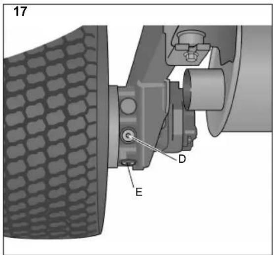
- Clean carefully around the oil plugs (17:D, E).
-
Place a container under the oil drain plug (17:E), remove the plug and let the oil run out into a container.
-
Remove the filler plug (17:D).
-
Install the oil drain plug.
Dispose of the oil according to local regulations.
- Fill with new oil via the filler plug hole. Pump in the oil with help of an oil can. Fill until the level reach the the filler plug hole.
Regarding type and volume of oil, see the table in 2.1.
- Install the filler plug.
- Tighten the plugs to 30 Nm.
6.10 BELT TRANSMISSIONS
After 5 hours of operation check that all belts are intact and not damaged.
6.11 CLEANING THE COOLING SYSTEM
All services should be carried out by authorised workshops.
6.12 BATTERY (8:M)

Acid that comes into contact with eyes or skin causes serious injury. If you come into contact with acid, immediately rinse with water and contact a doctor.
The battery is a valve-regulated battery with 12 V nominal voltage. The battery fluid does not need to and cannot be checked or topped up. The only maintenance that is required is charging, for example after extended storage.

The battery must be fully charged before being used for the first time. The battery must always be stored fully charged. If the battery is stored while discharged, serious damage will occur.
6.12.1 Charging with the engine
The battery can also be charged using the engine's alternator as follows:
- Install the battery in the machine as shown below.
- Place the machine outdoors or install an extraction device for the exhaust fumes.
- Start the engine according to the instructions in the user guide.
- Allow the engine to run continuously for 45 minutes.
- Stop the engine. The battery will now be fully charged.
6.12.2 Charging using battery charger
When charging with the battery charger, a battery charger with continuous voltage must be used.
Contact your dealer to purchase a battery charger with constant voltage.
The battery can be damaged if a standard type battery charger is used.
6.12.3 Removal/Installation

The current must be cut using the main switch (1:E2) before disconnecting the battery.

If the cables are interchanged, the generator and the battery will be damaged.

Tighten the cables securely. Loose cables can cause a fire.

The engine must never be driven with the battery disconnected. There is a risk of serious damage to the alternator and the electrical system.
Remove/install the battery as follows:
- Cut the power using the main switch (1:E2).
- Remove the left-hand engine cover.
- Disconnect the battery's cable connections and remove the battery.
- Install the battery in reverse order. Connect the red cable to the battery's positive terminal (+) and the black cable to the battery's negative terminal (-).
- Activate the main switch.
6.12.4 Cleaning
If the battery terminals are coated with oxide, they should be cleaned. Clean the battery terminals with a wire brush and grease them using terminal grease.
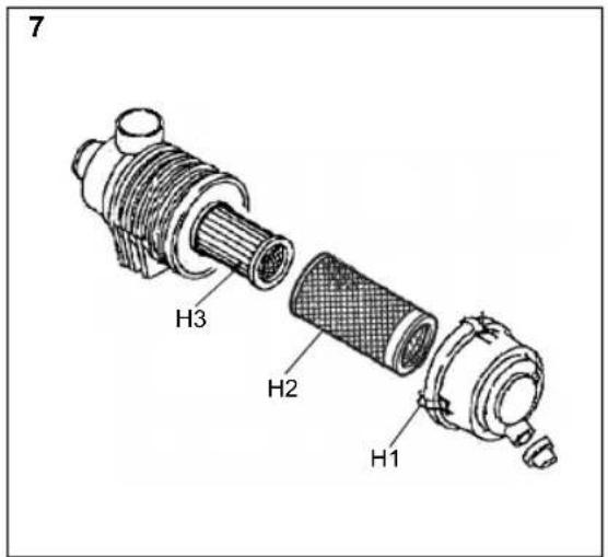
6.13 AIR FILTER, ENGINE

The engine must never be run when the air filter is damaged or without an air filter. Risk of serious engine damage.
The air filter consists of two filters as follows: 7:H2Pre-filter
7:H3Inner air filter
NOTE! Clean/replace the filters more often than stated in the maintenance schedule if the machine operates in dusty conditions.
Clean/replace the air filters as follows.
- Open the filter housing by releasing the two clamps (7:H1).
- Remove the pre-filter (7:H2) and leave the inner filter (7:H3) in place so that dust etc. does not penetrate the engine when the pre-filter is being blow cleaned.
-
Blow clean the pre-filter. Take care not to damage the filter. Blow from the inside out using compressed air. The pressure must be 3-5 bar. If the pre-filter cannot be cleaned or if it is damaged it must be replaced.
-
Clean the filter housing internally.
-
If the air filter must be replaced, pull this out as well.
-
Reassemble all parts in the reverse order.
-
Reset the filter indicator if it has tripped. See 3.5.9.
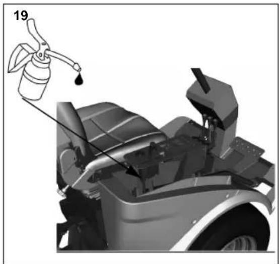
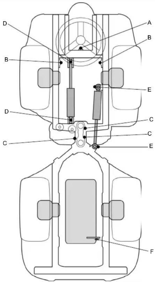
6.14 LUBRICATION
All lubrication points according to the table below must be lubricated after every 50 operating hours as well as after each clean.
Use a grease gun, filled with universal grease. Pump until grease protrudes. The lubrication points are shown in fig. 19-20.

Note the belts when lubricating. Belts must not come into contact with oil or grease.
| Object Lubrication nipples / action | Fig. | |
| Tension arm, pump belt | 1 lubrication nipple. 20:F | |
| Lifting fork, turning | 1 lubrication nipple 20:A | |
| Lifting fork, up-down | 2 lubrication nipples 20:B | |
| Lifting cylinder 2 | lubrication nipples 20:D | |
| Control cylinder 2 | lubrication nipples 20:E | |
| Pivot point 3 lubrication nipples 20:C | ||
| Throttle cable Lubricate the cable ends using an oil can at the same time as activating the respective control. Preferably carried out by two people. | 19 | |
6.15 VALVES
Valve adjustment and grinding should be carried out by authorised workshops.
6.16 FUSES

The current strengths given in this section are the maximum values of the fuse that may be installed. If a higher current fuse is installed there is a risk of fire damage to the machine.
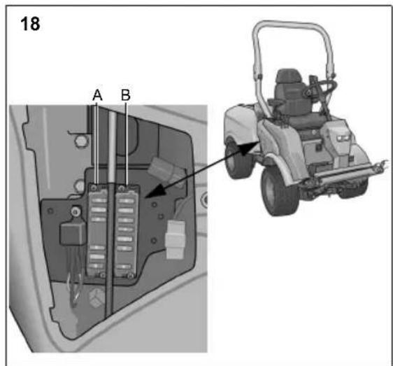
The machine has two fuse boxes.
Two fuse boxes (18:A and 18:B) are located in accordance with fig. 18. These contain the fuses according to the table below. Depending on the configuration of the machine some of the locations may be empty.
In the event of electrical faults, check and replace blown fuses. If the fault persists, contact an authorised workshop.
| Fault | Fuse | |
| Location | Rating | |
| Dipped beam 18:A1 20 A | ||
| AC 18:A2 20 A | ||
| Main fuse, cabin | 18:A3 30 | A |
| Turn signal lamps | 18:A4 10 | A |
| Spare | 18:A5 | |
| Parking lights, Horn, Dipped beam relay | 18:A6 10 | A |
| Hazard | 18:A7 10 | A |
| AC 18:A8 10 A | ||
| Indicator lamps, buzzer, hold valve transport position | 18:B1 10 | A |
| Cutting height, sand spreader, rear rake | 18:B2 20 | A |
| Cruise control, alternator | 18:B3 10 A | |
| Electric socket on panel | 18:B4 10 | A |
| Shut off pull | 18:B5 30 | A |
| PTO, warning lamp parking, safety relay | 18:B6 10 | A |
| Spare | 18:B7 | |
| Main fuse | 18:B8 40 | A |
GGP reserves the right to make alterations to the product without prior notification
1 GÉNÉRALITÉS

Attention aux projections.

3.5 INDICATIELAMPJES
3.5.1 Brandstofmeter (1:I1)
6.1 PROGRAMMA DI ASSISTENZA
6.6 AZ ABRONCSOK NYOMÁSA
2.1 DUOMENYS APIE MAŠINA