STHT77065 - Rangefinder STANLEY - Free user manual and instructions
Find the device manual for free STHT77065 STANLEY in PDF.
User questions about STHT77065 STANLEY
0 question about this device. Answer the ones you know or ask your own.
Ask a new question about this device
Download the instructions for your Rangefinder in PDF format for free! Find your manual STHT77065 - STANLEY and take your electronic device back in hand. On this page are published all the documents necessary for the use of your device. STHT77065 by STANLEY.
USER MANUAL STHT77065 STANLEY
text_image
88.839" 88.839"www.2helpU.com

text_image
UK CA CE ×Please read these instructions before operating the product.
Figures
A
text_image
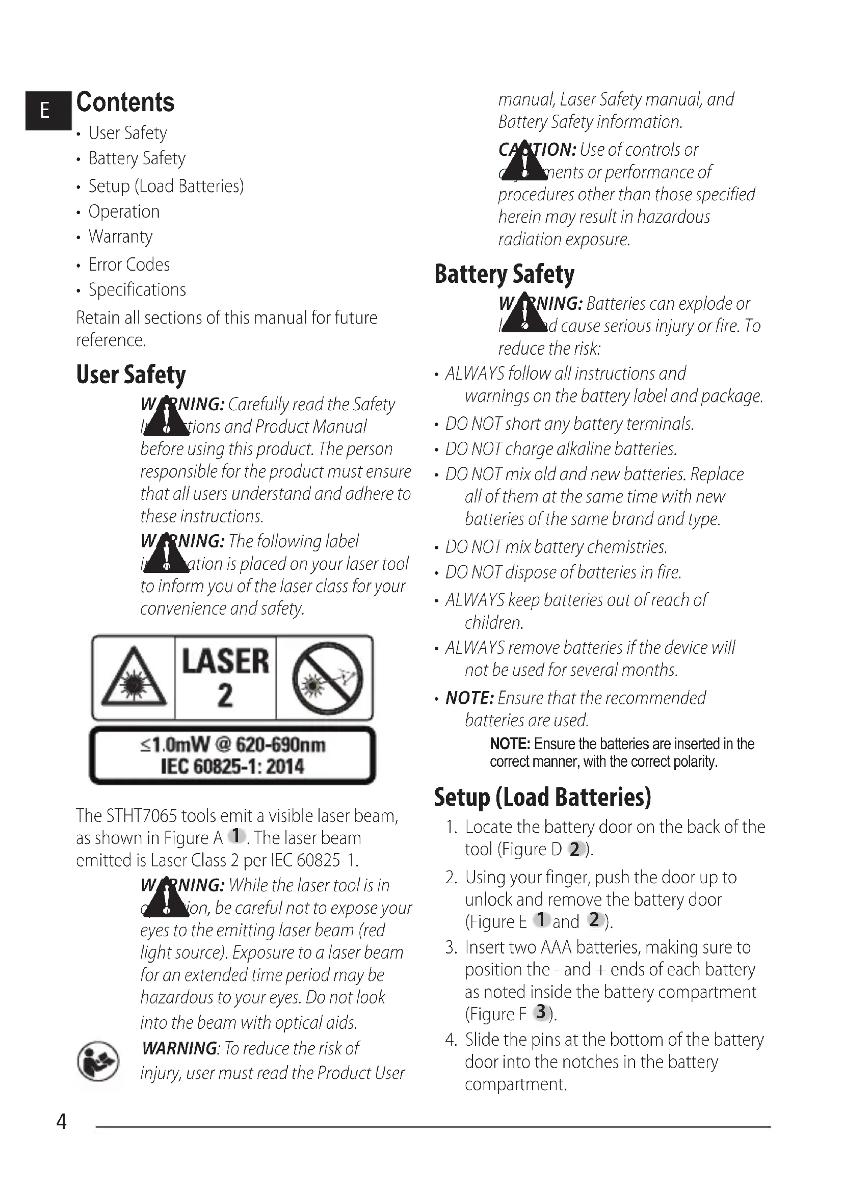
res ① ② 4:58.8.8" 3 4 ①B
text_image
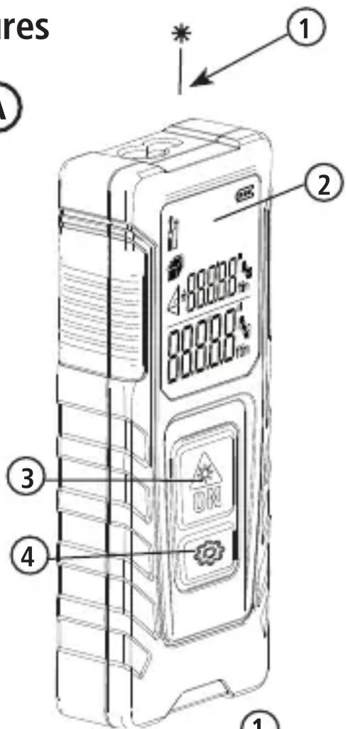
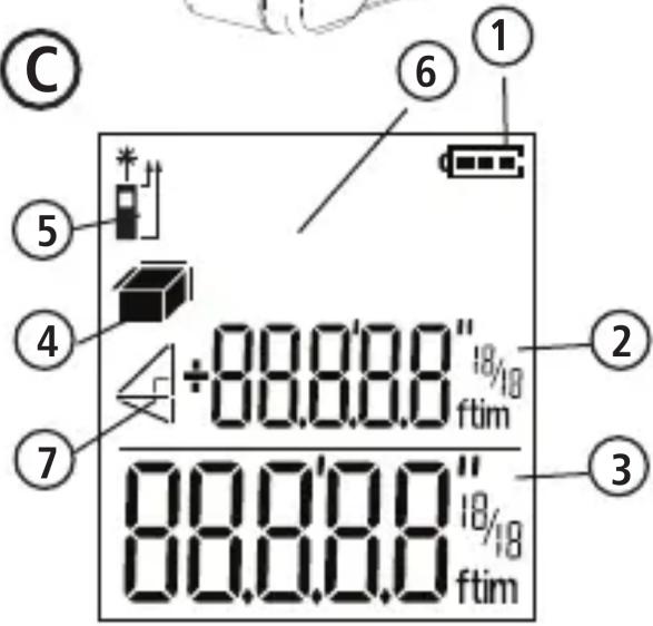
① ② ÷88.0'0.9" ftim 88.0'0.9" ftimC
text_image
C ⑤ ④ ⑦ ⑥ ① +80.0.0.0" ftim ② 80.0.0.0" ftim ③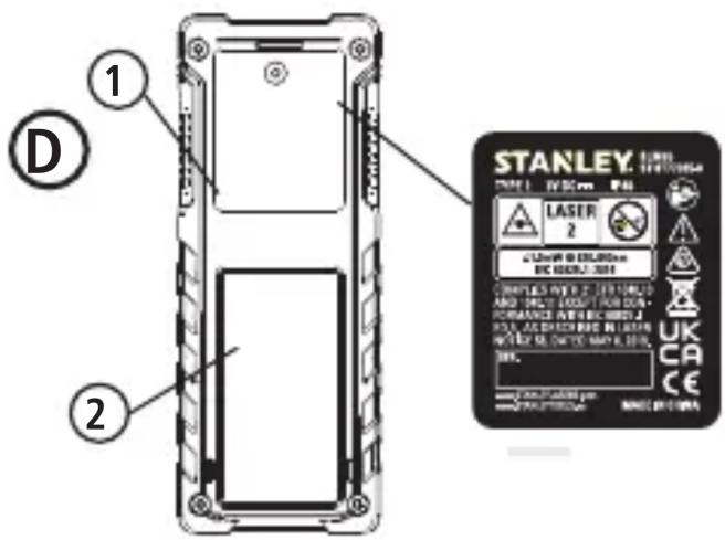
text_image
STANLEY TYPE: 10000000000 Laser 2 C:\Users\B\DELIR\Max R/C\MAX.2.304 CONTENTS BY: 2 (1/1) / 100% AND DUCT LENGTH FOR OUT FORMANCE WITH R/C\MAX.2 R/S, AS CHECKING IN LASER NOTICE OR CAN'T TO ANY E, ONLY 30%. STANLEY®E
text_image
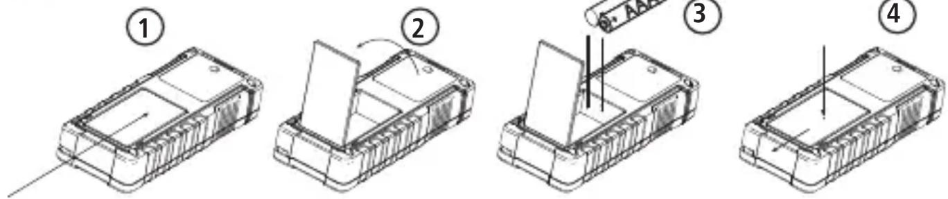
Technical diagram showing four steps of a device component assembly, labeled 1 to 4 with numbered annotations.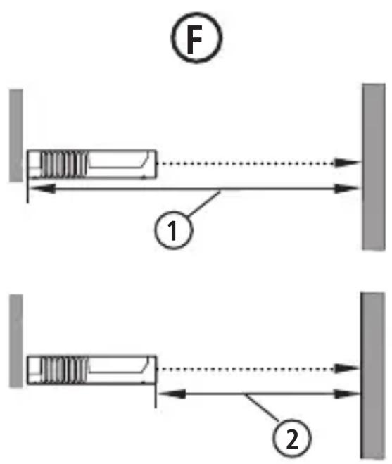
text_image
F ① ②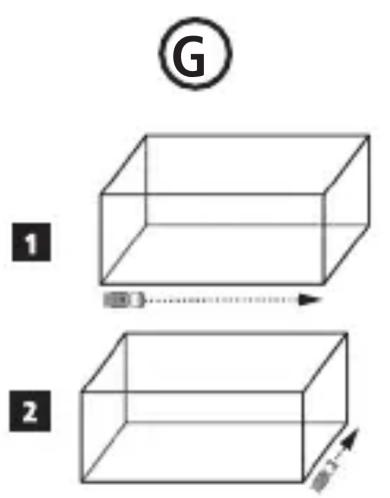
text_image
G 1 2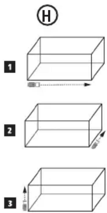
text_image
H 1 2 3E
Contents
- User Safety
- Battery Safety
- Setup (Load Batteries)
- Operation
- Warranty
- Error Codes
- Specifications
Retain all sections of this manual for future reference.
User Safety
WARNING: Carefully read the Safety Instructions and Product Manual before using this product. The person responsible for the product must ensure that all users understand and adhere to these instructions.
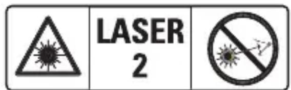
WARNING: The following label information is placed on your laser tool to inform you of the laser class for your convenience and safety.
text_image
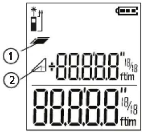
LASER 2
text_image
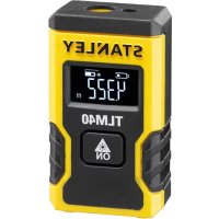
≤1.0mW @ 620-690nm IEC 60825-1: 2014The STHT7065 tools emit a visible laser beam, as shown in Figure A 1. The laser beam emitted is Laser Class 2 per IEC 60825-1.
WARNING: While the laser tool is in operation, be careful not to expose your eyes to the emitting laser beam (red light source). Exposure to a laser beam for an extended time period may be hazardous to your eyes. Do not look into the beam with optical aids.

WARNING: To reduce the risk of injury, user must read the Product User
manual, Laser Safety manual, and Battery Safety information.
CAUTION: Use of controls or adjustments or performance of procedures other than those specified herein may result in hazardous radiation exposure.
Battery Safety
WARNING: Batteries can explode or land cause serious injury or fire. To reduce the risk:
- ALWAYS follow all instructions and warnings on the battery label and package.
• DO NOT short any battery terminals.
• DO NOT charge alkaline batteries. - DO NOT mix old and new batteries. Replace all of them at the same time with new batteries of the same brand and type.
• DO NOT mix battery chemistries.
• DO NOT dispose of batteries in fire. - ALWAYS keep batteries out of reach of children.
- ALWAYS remove batteries if the device will not be used for several months.
- NOTE: Ensure that the recommended batteries are used.
NOTE: Ensure the batteries are inserted in the correct manner, with the correct polarity.
Setup (Load Batteries)
-
Locate the battery door on the back of the tool (Figure D 2).
-
Using your finger, push the door up to unlock and remove the battery door (Figure E 1 and 2).
-
Insert two AAA batteries, making sure to position the - and + ends of each battery as noted inside the battery compartment (Figure E 3).
-
Slide the pins at the bottom of the battery door into the notches in the battery compartment.
-
Push the battery door down until it snaps in place (Figure E 4).
When the tool is ON, the battery level appears in the display window (Figure C 1).
SETUP LDM
Turn On Tool
Click On (Figure A 3) to turn on the tool.
Changing the Reference Location
The tool will measure the distance from the bottom (Figure F 1) or top (Figure F 2) of the tool to the wall or object.
- Press and hold the gear button (Figure A 4) for 3 seconds. The measurement reference location icon (Figure C 5) will flash on the display window.
- Press the gear button again to change the reference location.
- Press the On button (Figure A 3) to confirm the reference location.
Changing the Unit of Measure
Once the current measurement is taken (the device is not in Continuous Measure mode), you can change the unit of measure from decimal ft (6.21 ft) to fractional ft (6'02"9/16), fractional ft to meters (1.894 m), meters to inches (74 9/16 in), or inches to decimal ft.
- To change the measurement unit, hold the gear button (Figure A 4) for three seconds to enter the units menu. Press the on button to confirm your reference location. Once confirmed, the current unit of measurement will be displayed, press the gear to change units and the on button to confirm.
OPERATION
Measuring Distance to a Wall or Object
-
Point the laser (Figure A 1) toward the wall or object whose distance you need to measure (Figure F).
-
Press On button (Figure A 3) to measure the distance from the tool to the wall or object. Refer to Setup LDM to change the reference location and / or unit of measurement.
- At the bottom of the display window (Figure A 2), view the current measurement (Figure C 3), which will keep changing as you move the tool.
To record the measurement click On. To record another measurement, click On again. Then repeat steps 1-3.
Measuring Area
You can measure the area of a wall, floor, or object.
- Press the gear button (Figure A 4) once to show the area icon (Figure B 1) on the display window (Figure A 2).
Measure the length.
- Position the tool at one end of the target and point the laser dot across the length. (Figure G 1) shows where to position the tool if measuring from the top of the tool.)
- Press On to display the length measurement on the first line of the display window.
Measure the width.
- Point the top of the tool at one side of the target (wall, floor, or object).
- Position the tool at one end of the target and point the laser dot across the width. (Figure G 2 shows where to position the tool if you are measuring from the top of the tool.)
- Press On to display the width measurement at the top of the display window.
View the Area measurement at the bottom of the display window (Figure E 3).
E
Measuring Volume
You can measure the volume of a room or object.
- Press the gear button (Figure A 4) three times to show the volume icon on the display window (Figure C 3).
Measure the width.
- Point the top of the tool at one side of the target (room or object).
- Position the tool at one end of the target and point the laser dot across the width. (Figure H 1) shows where to position the tool if you are measuring from the top of the tool.)
- Press to display the width measurement at the top of the display window.
Measure the length.
- Position the tool at one end of the target and point the laser dot across the length. (Figure H 2) shows where to position the tool if you are measuring from the top of the tool.)
- Press On to display the length measurement on the second line of the display window.
Measure the height.
- Positon the tool at one end of the target and point the laser dot across the height. (Figure H 3 shows where to position the tool if you are measuring from the bottom of the tool).
- Press On to display the height measurement on the third line of the display window.
View the Volume measurement at the bottom of the display window (Figure C 3).
Adding Measurements
You can add two measurements to get a total measurement of the two distances.
- Press gear button (Figure A 4) to show the addition icon on the display window (Figure C 4)
- Press On button (Figure A 3) to measure the distance from the tool to the wall or object.
- Press the On button to record the first measurement on the top line.
- Point the laser (Figure A 1) toward the next wall or object.
- Press the On button to record the second measurement on the middle line.
- View the total of the two measurements at the bottom of the display window (Figure C 3).
Subtracting Measurements
You can subtract one measurement from another.
- Press gear button (Figure A 4) to show the subtraction icon on the display window (Figure C 3).
- Point the laser at the top of the tool laser (Figure A 1) toward the wall or object whose distance you need to measure.
- Press On button (Figure A 3) to measure the distance from the tool to the wall or object.
- Press the On button to record the first measurement on the top line.
- Point the laser at the top of the tool toward the next wall or object.
- Press the On button to record the second measurement on the middle line.
- View the difference of the two measurements at the bottom of the display window (Figure C 3).
NOTE: If Second measurement is larger than first: IC 601 will be displayed for a negative number. Please switch measurement points so first measurement is larger than second.
Turning Off the Tool
The tool can be turned off in either of these ways:
- Press and hold the on button (Figure A 3) for several seconds (until the display window clears).
- If you do not use the tool for 180 seconds, it will automatically turn off.
Three Year Limited Warranty
Stanley warrants this product for a period of (2) years against deficiencies in material and workmanship. This LIMITED WARRANTY does not cover products that are improperly used, abused, altered or repaired. Please call 800-262-2161 for more information or return instructions. Unless otherwise noted, Stanley will repair without cost, any Stanley product found to be defective, including parts and labor charges, or at Stanley's option, will replace such tools or refund the purchase price, less the amount for depreciation, in exchange for the defective tool. THIS LIMITED WARRANTY EXCLUDES ALL INCIDENTAL OR CONSEQUENTIAL DAMAGES. Some states do not allow the exclusion or limitation of incidental or consequential damages, so these limitations may not apply to you. This LIMITED LIFETIME WARRANTY gives you specific legal rights that may vary from state to state. In addition to the warranty, STANLEY Lasers are covered by: 30-Day Money Back Guarantee. If you are not completely satisfied with the performance of your STANLEY Laser for any reason, you can return it within 30 days from the date of purchase with a receipt for a full refund.
Protecting the Environment

Separate collection. Products and batteries marked with this symbol must not be disposed of with normal household waste.
Products and batteries contain materials that can be recovered or recycled reducing the demand for raw materials. Please recycle electrical products and batteries according to local provisions. Further information is available at www.2helpU.com.
Batteries
- When disposing batteries, think of the protection of the environment.
- Check with your local authorities for an environmentally safe way of battery disposal.
If INFO appears on the display window with a Code number, perform the corresponding Corrective Action.
| Code | Description Corrective Action | |
| IC101 | Received signal too high | Target is too reflective. Use the target plate or change the target surface. |
| IC201 | Too much background light Reduce the background light on the target area. | |
| IC302 | Temperature out of range Allow device too warm or cool and repeat measurement | |
| IC303 | Distance not in range or signal too low | Adjust range, if within range change target surface |
| IC401 | Battery too low for measurements | Recharge battery or change batteries if non-rechargeable |
| IC505 | Hardware error Switch the device on/off several times. If error still occurs, return device to Service Center or Distributor | |
| IC601 | Negative number Measure longer distance before shorter distance for positive result | |
| IC604 | Invalid measurement for calculation | Remeasure distances, hypotenuse must be larger than sides of triangle |
Specifications
E
| Range .2 m to 20m (7.9 in to 65 ft) | |
| Measuring Accuracy* ± 3 mm (± 1/8 in)* | |
| Resolution** 1 mm (1/16 in)** | |
| Laser Class Class 2 (IEC/EN60825-1: 2014) | |
| Laser Type ≤ 1.0 mW @ 620-690 nm | |
| Backlight Automatic Switch-off After 20s | |
| Laser After 120s | |
| Unit Automatic Switch-off After 180s | |
| Continuous Measuring Yes | |
| Area/Volume Yes | |
| Battery Life (2 x AAA) Up to 3000 Measurements | |
| Dimension (H x D x W) 120 x 48.5 x 26 mm (4.72 x 1.91 x 1.02 in) | |
| Weight (with Batteries) 100g (3.21 oz) | |
| Storage Temperature Range | -10 °C ~ +60 °C (14 °F ~ 140 °F) |
| Operating Temperature Range | 0 °C ~ +40 °C (32 °F ~ 104 °F) |
| *Measuring Accuracy depends on the current conditions:Under favorable conditions (good target surface, low background illumination, and room temperature), up to 30' (10 m). The measurement error can increase by ± 0.1 mm/m for distances over 30' (10 m)In unfavorable conditions (poor target surface, high background illumination, operating temperatures at the Upper or lower end of the temperature range), the measurement range may be reduced and the accuracy can increase to ± 6 mm for distances under 30' (10 m). Beyond 30' (10 m) the measurement error can increase by ±0.25 mm/m.**Resolution is the finest measurement you can see. In inches, that is 1/16". In mm, that is 1 mm. | |
Inhalt
D
UK: Stanley, Slough, England SL1 4DX
Made in China
NA082211
August 2021