GKS 36 VLI Professional - Saw BOSCH - Free user manual and instructions
Find the device manual for free GKS 36 VLI Professional BOSCH in PDF.
User questions about GKS 36 VLI Professional BOSCH
0 question about this device. Answer the ones you know or ask your own.
Ask a new question about this device
Download the instructions for your Saw in PDF format for free! Find your manual GKS 36 VLI Professional - BOSCH and take your electronic device back in hand. On this page are published all the documents necessary for the use of your device. GKS 36 VLI Professional by BOSCH.
USER MANUAL GKS 36 VLI Professional BOSCH
OBI_BUCH-3274-001. book Page 1 Wednesday, August 16, 2017 1:53 PM
Robert Bosch Power Tools GmbH
70538 Stuttgart
GERMANY
www.bosch-pt.com
160992A3ZU 2017.D8 AS/266 EURO

GKS 36 V-LI Professional

BOSCH
de Originalbetriebssanleitung
on original instructions
lr Notice original
es Manual original
pt Manual original
it Istruzioni original
nl Comprarekolike gbrubkaasa
da Original brugansvinsing
sv Bruksekinsing i original
no Original driftsinstrus
i Alkuperaset object
i lflprrumovogny sponny
tr Original lygme talmati
pl imbukca orignaia
ps Powindn oivk pouzialan
sk Powindn oivk npouzile
hu Erodiel bashali tasasitas
ru Oqnnnnepeyckpocpaepnoe no
uk Oomnivmbia hncryuaa 3 excyyaa 1 k
mopnncnnnne nnnnnnnnnnnnnnnnnnnnnnnnnnnnnnnnnnnnnnnnnnnnnnnnnnnnnnnnnnnnnnnnnnnnnnnnnnnnnnnnnnnnnnnnnnnnnnnnnnnnnnnnnnnnnnnnnnnnnnnnnnnnnnnnnnnnnnnnnnnnnnn
sr Originala upusstcs ra rad
slzirna navodpa
hr Originalae spu crad
et Aluparajra kazutubudur
hv Instrukas jagorendahtda
It Original instruktca
ko sae, sngi si hien
ar aee 1saaee


OBI_BUCH-3274-001.book Page 6 Wednesday, August 16, 2017 1:53 PM
6 | Deutsch
Deutsch
OBI_BUCH-3274-001.book Page 7 Wednesday, August 16, 2017 1:53 PM
Deutsch|7
OBI_BUCH-3274-001.book Page 9 Wednesday, August 16, 2017 1:53 PM
Deutsch|9
OBI_BUCH-3274-001.book Page 11 Wednesday, August 16, 2017 1:53 PM
Deutsch 11
OBI_BUCH-3274-001.book Page 13 Wednesday, August 16, 2017 1:53 PM
Deutsch 13
Wartung und Service
pack may create a risk of fire when used with another battery pack.
Use power tools only with specifically designated battery packs. Use of any other battery packs may create a risk of injury and fire.
When battery pack is not in use, keep it away from other metal objects, like paper clips, coins, keys, nails, screws or other small metal objects, that can make a connection from one terminal to another. Shorting the battery terminals together may cause burns or a fire.
Under abusive conditions, liquid may be ejected from the battery; avoid contact. If contact accidentally occurs, flush with water. If liquid contacts eyes, additionally seek medical help. Liquid ejected from the battery may cause irritation or burns.
Service
Have your power tool serviced by a qualified repair person using only identical replacement parts. This will ensure that the safety of the power tool is maintained.
SafetyWarnings for Circular Saws
Cutting procedures
DANGER: Keep hands away from cutting area and the blade. Keep your second hand on auxiliary handle, or motor housing. If both hands are holding the saw, they cannot be cut by the blade.
Do not reach underneath the workpiece. The guard cannot protect you from the blade below the workpiece.
Adjust the cutting depth to the thickness of the workpiece. Less than a full tooth of the blade teeth should be visible below the workpiece.
- Never hold piece being cut in your hands or across your leg. Secure the workpiece to a stable platform. It is important to support the work properly to minimize body exposure, blade binding, or loss of control.
Hold the power tool by insulated gripping surfaces only, when performing an operation where the cutting tool may contact hidden wiring. Contact with a "live" wire will also make exposed metal parts of the power tool "live" and could give the operator an electric shock.
When ripping, always use a rip fence or straight edge guide. This improves the accuracy of cut and reduces the chance of blade binding.
Always use blades with correct size and shape (diamond versus round) of arbour holes. Blades that do not match the mounting hardware of the saw will run eccentrically, causing loss of control.
- Never use damaged or incorrect blade washers or bolt. The blade washers and bolt were specially designed for your saw, for optimum performance and safety of operation.
Kickback causes and related warnings
- Kickback is a sudden reaction to a pinched, bound or misaligned saw blade, causing an uncontrolled saw to lift up and out of the workpiece toward the operator:
- When the blade is pinched or bound tightly by the kerf
closing down, the blade stalls and the motor reaction drives the unit rapidly back toward the operator; if the blade becomes twisted or misaligned in the cut, the teeth at the back edge of the blade can dig into the top surface of the wood causing the blade to climb out of the kerf and jump back toward the operator. Kickback is the result of saw misuse and/or incorrect operating procedures or conditions and can be avoided by taking proper precautions as given below.
- Maintain a firm grip with both hands on the saw and position your arms to resist kickback forces. Position your body to either side of the blade, but not in line with the blade. Kickback could cause the saw to jump backwards, but kickback forces can be controlled by the operator, if proper precautions are taken.
When blade is binding, or when interrupting a cut for any reason, release the trigger and hold the saw motionless in the material until the blade comes to a complete stop. Never attempt to remove the saw from the work or pull the saw backward while the blade is in motion or kickback may occur. Investigate and take corrective actions to eliminate the cause of blade binding. - When restarting a saw in the workpiece, centre the saw blade in the kerf and check that saw teeth are not engaged into the material. If saw blade is binding, it may walk up or kickback from the workpiece as the saw is restarted.
Support large panels to minimise the risk of blade pinching and kickback. Large panels tend to sag under their own weight. Supports must be placed under the panel on both sides, near the line of cut and near the edge of the panel.
Do not use dull or damaged blades. Unsharpened or improperly set blades produce narrow kerf causing excessive friction, blade binding and kickback.
Blade depth and bevel adjusting locking levers must be tight and secure before making cut. If blade adjustment shifts while cutting, it may cause binding and kickback.
Use extra caution when sawing into existing walls or other blind areas. The protruding blade may cut objects that can cause kickback.
Lower guard function
- Check lower guard for proper closing before each use. Do not operate the saw if lower guard does not move freely and close instantly. Never clamp or tie the lower guard into the open position. If saw is accidentally dropped, lower guard may be bent. Raise the lower guard with the retracting handle and make sure it moves freely and does not touch the blade or any other part, in all angles and depths of cut.
Check the operation of the lower guard spring. If the guard and the spring are not operating properly, they must be serviced before use. Lower guard may operate negligibly due to damaged parts, gummy deposits, or a build-up of debris.
Lower guard may be retracted manually only for special cuts such as "plunge cuts" and "compound cuts".
English | 15


OBI_BUCH-3274-001.book Page 16 Wednesday, August 16, 2017 1:53 PM
16|English
Raise lower guard by retracting handle and as soon as blade enters the material, the lower guard must be released. For all other sawing, the lower guard should operate automatically.
Always observe that the lower guard is covering the blade before placing saw down on bench or floor. An unprotected, coating blade will cause the saw to walk backwards, cutting whatever is in its path. Be aware of the time it takes for the blade to stop after switch is released.
Additional safety warnings
Don't reach into the chip ejector with your hands. They could be injured by rotating parts.
Do not work overhead with the saw. In this manner you do not have sufficient control over the power tool.
- Use appropriate detectors to determine if utility lines are hidden in the work area or call the local utility company for assistance. Contact with electric lines can lead to fire and electric shock. Damaging a gas line can lead to explosion. Penetrating a water line causes property damage.
Do not operate the power tool stationary. It is not designed for operation with a saw table.
- Do not use high speed steel (HSS) saw blades. Such saw blades can easily break.
Do not saw ferrous metals. Red hot chips can ignite the dust extraction.
When working with the machine, always hold it firmly with both hands and provide for a secure stance. The power tool is guided more securely with both hands.
Secure the workpiece. A workpiece clamped with clamping devices or in a vice is held more secure than by hand.
Always wait until the machine has come to a complete stop before placing it down. The tool insert can jam and lead to loss of control over the power tool.
Do not open the battery. Danger of short-circuiting. Protect the battery against heat, e.g., agai continuous intense sunlight, fire, water, an moisture. Danger of explosion.
In case of damage and improper use of the battery, vapours may be emitted. Ventilate the area and seek medical help in case of complaints. The vapours can irritate the respiratory system.
Use the battery only in conjunction with your Bosch power tool. This measure alone protects the battery against dangerous overload.
The battery can be damaged by pointed objects such as nails or screwdrivers or by force applied externally. An internal short circuit can occur and the battery can burn, smoke, explode or overheat.
Product Description and Specifications

Read all safety warnings and all instructions. Failure to follow the warnings and instructions may result in electric shock, fire and/or serious injury.
While reading the operating instructions, unfold the graphics page for the machine and leave it open.
Intended Use
The machine is intended for lengthways and crossways cutting of wood with straight cutting lines as well as mitre cuts in wood while resting firmly on the workpiece. With suitable saw blades, thin-walled non-ferrous metals, e.g., profiles, can also be sawed.
Working ferrous metals is not permitted.
Product Features
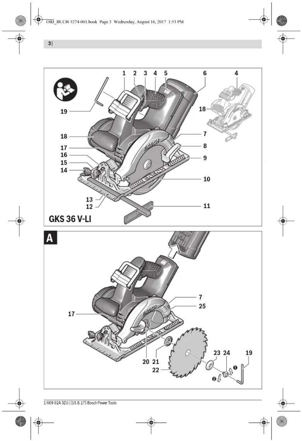
The numbering of the product features refers to the illustration of the machine on the graphics page.
1 Utility hook
2 Lock-off button for On/Off switch
3 On/Off switch
4 Handle (insulated gripping surface)
5 Battery unlocking button
6 Battery pack
7 Blade guard
8 Lever for retracting blade guard
9 Base plate
10 Retracting blade guard
11 Parallel guide
12 Cutting mark, 0^
13Cuttingmark,45°
14 Wing bolt for parallel guide
15 Wing bolt for bevel-angle preselection
16 Scale for mitre angle
17 Spindle lock button
18 Auxiliary handle (insulated gripping surface)
19 Hex key
20 Saw spindle
21 Mounting flange
22 Saw blade
23 Clamping flange
24 Clamping bolt with washer
25 Marks on the blade guard
26 Button for charge-control indicator
27 Battery charge-control indicator
28 Temperature control indicator
29 Cutting-depth scale
30 Clamping lever for cutting-depth preselection
31 Set of screw clamps
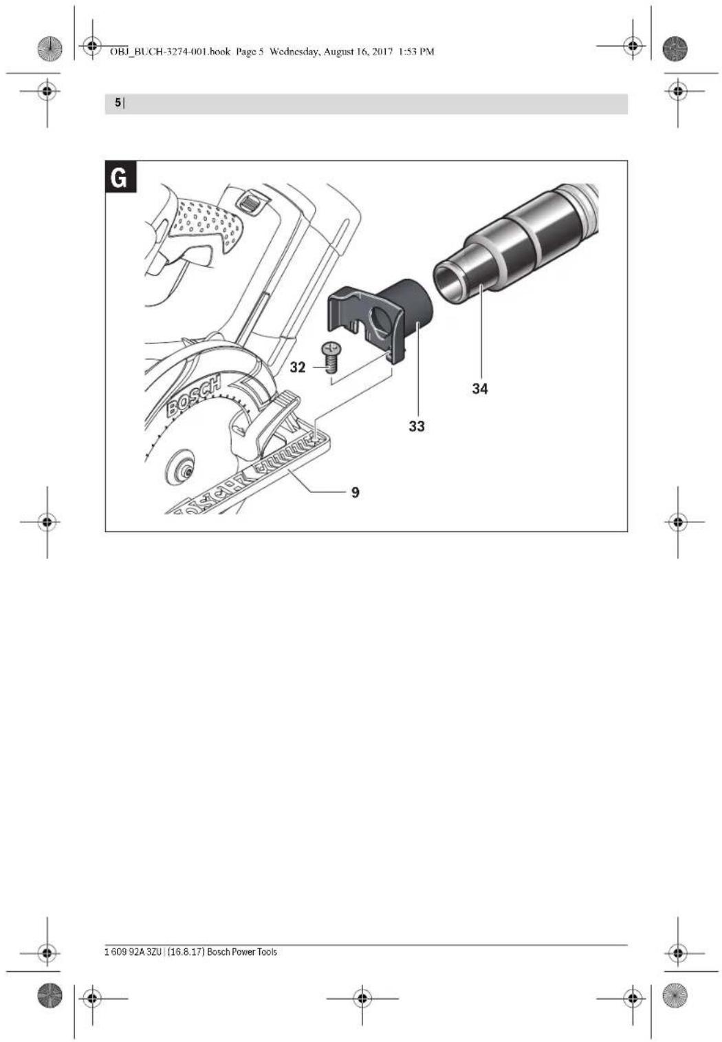
32 Fastening screw for extraction adapter
1 Utility hook
2 Lock-off button for On/Off switch
3 On/Off switch
4 Handle (insulated gripping surface)
5 Battery unlocking button
6 Battery pack
7 Blade guard
8 Lever for retracting blade guard
9 Base plate
10 Retracting blade guard
11 Parallel guide
12 Cutting mark, 0^
13Cuttingmark,45°
14 Wing bolt for parallel guide
15 Wing bolt for bevel-angle preselection
16 Scale for mitre angle
17 Spindle lock button
18 Auxiliary handle (insulated gripping surface)
19 Hex key
20 Saw spindle
22 Saw blade
23 Clamping flange
24 Clamping bolt with washer
25 Marks on the blade guard
26 Button for charge-control indicator
27 Battery charge-control indicator
28 Temperature control indicator
29 Cutting-depth scale
30 Clamping lever for cutting-depth preselection
31 Set of screw clamps
32 Fastening screw for extraction adapter


Product Features
The numbering of the product features refers to the illustration of the machine on the graphics page.


English|17
33 Extraction adapter
34Vacuum hose
*Accessories shown or described are not part of the standard delivery scope of the product. A complete overview of accessories can be found in our accessories program.
Technical Data
| Circular Saw GKS 36 V-LI | ||
| Article number | 3601 F73 ... | |
| Rated voltage | V=36 | |
| No-load speed | min- | 4000 |
| Cutting depth, max. | ||
| - for 0° bevel angle | mm | 54 |
| - for 45° bevel angle | mm | 38 |
| Spindle lock | ● | |
| Base plate dimensions | mm 146 x 290 | |
| Saw blade diameter, max. | mm 165 | |
| Saw blade diameter, min. | mm 160 | |
| Blade thickness, max. | mm 1.7 | |
| Blade thickness, min. | mm 1.0 | |
| Tooth thickness/setting, max. | mm 2.6 | |
| Mounting bore | mm 20 | |
| Weight according to EPTA-Procedure 01:2014 | kg | 4.3 - 5.0* |
| Permitted ambient temperature | ||
| - during charging | °C | 0...+45 |
| - during operation and during storage | °C | -20...+50 |
| Recommended batteries | GBA 36V | |
| Recommended chargers | AL 36.. | |
| GAL 36.. | ||
depending on the battery pack being used
**limited performance at temperatures <0°C
Noise/Vibration Information
Sound emission values determined according to
EN60745-2-5
Typically the A-weighted noise levels of the product are:
Sound pressure level 98 dB(A); Sound power level
109 dB(A). Uncertainty K=1.5 dB.
Wear hearing protection!
Vibration total values a_t (triax vector sum) and uncertainty K determined according to EN 60745-2-5:
a<2.5m/s²,K=1.5m/s²
The vibration level given in this information sheet has been measured in accordance with a standardised test given in EN 60745 and may be used to compare one tool with another. It may be used for a preliminary assessment of exposure. The declared vibration emission level represents the main applications of the tool. However if the tool is used for different applications, with different accessories or insertion tools or is poorly maintained, the vibration emission may differ. This may significantly increase the exposure level over the total working period.
An estimation of the level of exposure to vibration should also take into account the times when the tool is switched off or when it is running but not actually doing the job. This may significantly reduce the exposure level over the total working period.
Identify additional safety measures to protect the operator from the effects of vibration such as: maintain the tool and the accessories, keep the hands warm, organisation of work patterns.
Assembly
Battery Charging
- Use only the battery chargers listed on the accessories page. Only these battery chargers are matched to the lithium-ion battery of your power tool.
Note: The battery supplied is partially charged. To ensure full capacity of the battery, completely charge the battery in the battery charger before using your power tool for the first time. The lithium-ion battery can be charged at any time without reducing its service life. Interrupting the charging procedure does not damage the battery.
The lithium-ion battery is protected against deep discharging by the "Electronic Cell Protection (ECP)". When the battery is empty, the machine is switched off by means of a protective circuit. The inserted tool no longer rotates.
Do not continue to press the On/Off switch after the machine has been automatically switched off. The battery can be damaged.
Observe the notes for disposal.
Removing the battery
The battery 6 is equipped with two locking levels that should prevent the battery from falling out when pushing the battery unlocking button 5 unintentionally. As long as the battery is inserted in the power tool, it is held in position by means of a spring.
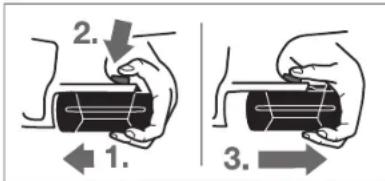
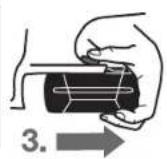
To remove the battery 6:
- Push the battery against the base of the power tool (1.) and at the same time press the battery unlocking button 5 (2.).
- Pull the battery out of the power tool until a red stripe becomes visible (3.).
- Press the battery unlocking button 5 again and pull out the battery completely.


18|English
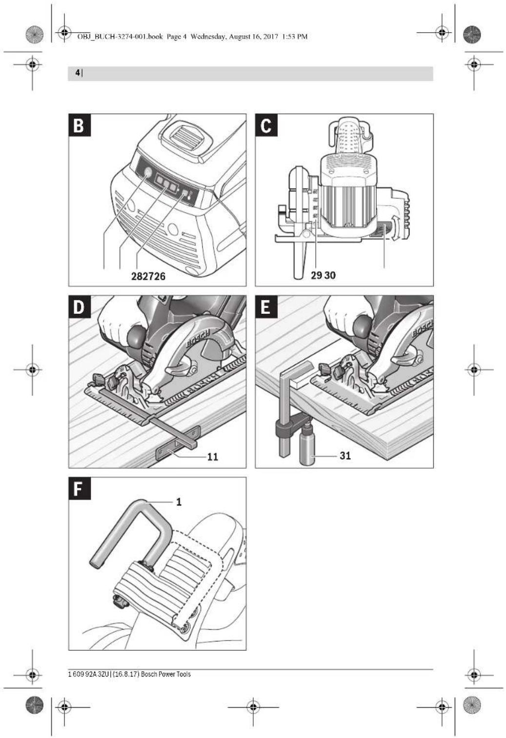
Battery Charge-control Indication (see figure B)
The three green LEDs of the battery charge-control indicator 27 indicate the charge condition of the battery 6. For safety reasons, it is only possible to check the status of the charge condition when the machine is at a standstill.
Push button 26 to indicate the charge condition (also possible when the battery is removed). The battery charge-control indicator automatically goes out after approx. 5 seconds.
LED Capacity
Continuous lighting 3 × green ≥ 2/3
Continuous lighting 2 x green ≥ 1 / 3
Continuous lighting 1 x green <1/3
Flashing light 1 x green Reserve
When no LED lights up after pushing button 26, then the battery is defective and must be replaced.
During the charging procedure, the three green LEDs light up one after the other and briefly go out. The battery is fully charged when the three green LEDs light up continuously. The three LEDs go out again approx. 5 minutes after the battery has been fully charged.
Mounting/Replacing the Saw Blade
Before any work on the power tool, remove the battery.
When mounting the saw blade, wear protective gloves. Danger of injury when touching the saw blade.
Only use saw blades that correspond with the characteristic data given in the operating instructions.
Do not under any circumstances use grinding discs as the cutting tool.
Selecting a Saw Blade
An overview of recommended saw blades can be found at the end of this manual.
Removal of the Saw Blade (see figure A)
For changing the cutting tool, it is best to place the machine on the face side of the motor housing.
- Press the spindle lock button 17 and keep it pressed.
The spindle lock button 17 may be actuated only when the saw spindle is at a standstill. Otherwise, the power tool can be damaged.
With the hex key 19, unscrew the clamping bolt 24 turning in rotation direction. - Tilt back the retracting blade guard 10 and hold firmly. Remove the clamping flange 23 and the saw blade 22 from the saw spindle 20.
Mounting the Saw Blade (see figure A)
For changing the cutting tool, it is best to place the machine on the face side of the motor housing.
- Clean the saw blade 22 and all clamping parts to be assembled.
- Tilt back the retracting blade guard 10 and hold firmly.
- Place the saw blade 22 onto the mounting flange 21. The cutting direction of the teeth (direction of arrow on the saw blade) and the direction-of-rotation arrow on the retracting blade guard 10 must correspond.
Mount the clamping flange bolt 24 turning in rotation direction. Observe correct mounting position of mounting flange 21 and clamping flange 23.
- Press the spindle lock button 17 and keep it pressed.
- Tighten the clamping bolt 19 with the Allen key 24 by turning in rotation direction . The tightening torque is 6 - 9Nm , which corresponds to hand tight plus 14 turn or 3 graduation marks of the marks 25 on the blade guard 7.
23 and screw in the clamping
Dust/Chip Extraction
Before any work on the power tool, remove the battery.
Dust from materials such as lead-containing coatings, some wood types, minerals and metal can be harmful to one's health. Touching or breathing in the dust can cause allergic reactions and/or lead to respiratory infections of the user or bystanders.
Certain dust, such as oak or beech dust, is considered carcinogenic, especially in connection with wood-treatment additives (chromate, wood preservative). Materials containing asbestos may only be worked by specialists.
To achieve a high degree of dust extraction, use the vacuum cleaner type GAS 25/GAS 50/GAS 50M for wood or GAS 50 MS for wood and/or mineral dust in conjunction with this power tool.
- Provide for good ventilation of the working place.
- It is recommended to wear a P2 filter-class respirator.
Observe the relevant regulations in your country for the materials to be worked.
Prevent dust accumulation at the workplace. Dust can easily ignite.
Mounting the Extraction Adapter (see figure G)
Fasten the extraction adapter 33 to the base plate 9 with the fastening screw 32.
A vacuum hose with a diameter of 35mm can be connected to the extraction adapter 33.
The extraction adapter may not be mounted when no external dust extraction is connected. Otherwise the extraction channel can become clogged.
Do not connect a dust bag to the extraction adapter.
Otherwise the extraction system can become clogged.
To ensure optimum extraction, the extraction adapter 33 must be cleaned regularly.
External Dust Extraction
Connect the vacuum hose 34 to a vacuum cleaner (accessory). An overview for connecting to various vacuum cleaners can be found at the end of this manual.
The vacuum cleaner must be suitable for the material being worked.
When vacuuming dry dust that is especially detrimental to health or carcinogenic, use a special vacuum cleaner.
Operation
Operating Modes
Before any work on the power tool, remove the battery.
1609 92A 3ZU| (16.8.17) Bosch Power Tools


English | 19
Adjusting the Cutting Depth (see figure C)
Adjust the cutting depth to the thickness of the workpiece. Less than a full tooth of the blade teeth should be visible below the workpiece.
Loosen the clamping lever 30. For a smaller cutting depth, pull the saw away from the base plate 9; for a larger cutting depth, push the saw toward the base plate 9. Adjust the desired cutting depth at the cutting-depth scale. Tighten the clamping lever 30 again.
The tightening tension of the clamping lever 30 can be readjusted. For this, unscrew the clamping lever 30, and screw it back again turned offset by at least 30^ in anticlockwise direction.
Adjusting the Cutting Angle
It is best to place the machine on the face side of the blade guard 7.
Loosen wing bolt 15. Tilt the saw sideways. Adjust the desired setting at the scale 16. Tighten wing bolt 15 again.
Note: For bevel cuts, the cutting depth is smaller than the setting indicated on the cutting-depth scale 29.
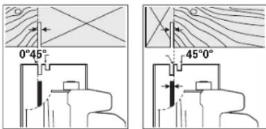
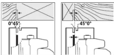
Cutting Marks
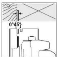
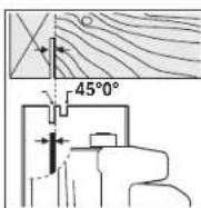
The 0^ cutting mark 12 indicates the position of the saw blade for right-angled cuts. The 45^ cutting mark 13 indicates the position of the saw blade for 45^ cuts.
For precise cuts, position the circular saw against the workpiece as shown in the figure. It is best to carry out a trial cut
Starting Operation
Inserting the battery
Insert the charged battery 6 from the front into the base of the power tool. Push the battery completely into the base until the red stripe can no longer be seen and the battery is securely locked.
Switching On and Off
To start the machine, first push the lock-off button for the On/Off switch 2 and then press the On/Off switch 3 and keep it pressed.
To switch off the machine, release the On/Off switch 3.
Note: For safety reasons, the On/Off switch 3 cannot be locked; it must remain pressed during the entire operation.
To save energy, only switch the power tool on when using it.
Run-on Brake
An integrated run-on brake reduces the run-on period of the saw blade after switching off the machine.
Temperature Control Indicator
The red LED of the temperature control indicator 28 signals that the battery or the electronics of the power tool (when the battery is inserted) are not within the optimum temperature range. In this case, the power tool will not operate at full capacity.
Temperature control of the battery:
The red LED 28 lights up continuously after inserting the battery into the charger: The battery is not within the charging temperature range between 0^ and 45^ and cannot be charged.
- The red LED 28 flashes when you press the 26 button or the On/Off switch 3 (with battery inserted): The battery is outside of the permitted operating temperature range.
For battery temperatures over 70^ the power tool switches off until the battery is in the optimal temperature range again.
Temperature control of the power tool electronics:
The red LED 28 lights up continuously when pressing the On/Off switch 3: The temperature of the machine's electronics is below 5^ or above 75^ .
- At a temperature above 90^ , the electronics of the power tool switch off until the temperature is within the allowable temperature range again.
Protection Against Deep Discharging
The lithium-ion battery is protected against deep discharging by the "Electronic Cell Protection (ECP)". When the battery is empty, the machine is switched off by means of a protective circuit. The inserted tool no longer rotates.
Working Advice
Protect saw blades against impact and shock.
Guide the machine evenly and with light feed in the cutting direction. Excessive feed significantly reduces the service life of the saw blade and can cause damage to the power tool.
Sawing performance and cutting quality depend essentially on the condition and the tooth form of the saw blade. Therefore, use only sharp saw blades that are suited for the material to be worked.
Sawing Wood
The correct selection of the saw blade depends on the type and quality of the wood and whether lengthway or crossway cuts are required.
When cutting spruce lengthways, long spiral chips are formed.
Beech and oak dusts are especially detrimental to health. Therefore, work only with dust extraction.
Sawing with Parallel Guide (see figure D)
The parallel guide 11 enables exact cuts along a workpiece edge and cutting strips of the same dimension.
Sawing with Auxiliary Guide (see figure E)
For sawing large workpieces or straight edges, a board or strip can be clamped to the workpiece as an auxiliary guide; the base plate of the circular saw can be guided alongside the auxiliary guide.


OBI_BUCH-3274-001.book Page 21 Wednesday, August 16, 2017 1:53 PM
Francais 21
Western Cape - BSC Service Centre
Democracy Way, Prosperity Park
Milnerton
Tel.: (021) 5512577
Fax: (021) 5513223
E-Mail: bsc@zsd.co.za
Bosch Headquarters
Midrand, Gauteng
Tel.: (011) 6519600
Fax: (011) 6519880
E-Mail: rbsa-hq.pts@za.bosch.com
Transport
The contained lithium-ion batteries are subject to the Dangerous Goods Legislation requirements. The user can transport the batteries by road without further requirements.
When being transported by third parties (e.g.: air transport or forwarding agency), special requirements on packaging and labelling must be observed. For preparation of the item being shipped, consulting an expert for hazardous material is required.
Dispatch batteries only when the housing is undamaged. Tape or mask off open contacts and pack up the battery in such a manner that it cannot move around in the packaging. Please also observe possibly more detailed national regulations.
Disposal

The machine, rechargeable batteries, accessories and packaging should be sorted for environmental-friendly recycling.

Do not dispose of power tools and batteries/rechargeable batteries into household waste!
Only for EC countries:

According to the European Guideline 2012/19/EU, power tools that are no longer usable, and according to the European Guideline 2006/66/EC, defective or used battery packs/batteries, must be collected separately and disposed of in an environmentally correct manner.
Batteries no longer suitable for use can be directly returned at:
Great Britain
Robert Bosch Ltd. (B.S.C.)
P.O.Box 98
Broadwater Park
North Orbital Road
Denham
Uxbridge
UB95HJ
At www.bosch-pt.co.uk you can order spare parts or arrange
the collection of a product in need of servicing or repair.
Tel. Service: (0344) 7360109
E-Mail: boschservicecentre@bosch.com
Battery packs/batteries:
Li-ion:
Please observe the instructions in section "Transport", page 21.
Subject to change without notice.
Français
OBI_BUCH-3274-001.book Page 29 Wednesday, August 16, 2017 1:53 PM
Espanol|29
Robert Bosch (France) S.A.S.
OBI_BUCH-3274-001.book Page 33 Wednesday, August 16, 2017 1:53 PM
OBI_BUCH-3274-001.book Page 37 Wednesday, August 16, 2017 1:53 PM
Espanol|37
OBI_BUCH-3274-001.book Page 41 Wednesday, August 16, 2017 1:53 PM
OBI_BUCH-3274-001.book Page 44 Wednesday, August 16, 2017 1:53 PM
44 | Português
Aspiração externa
OBI_BUCH-3274-001.book Page 58 Wednesday, August 16, 2017 1:53 PM
58|Nederlands
OBI_BUCH-3274-001.book Page 61 Wednesday, August 16, 2017 1:53 PM
Nederlandsl 61
Snelstop
OBI_BUCH-3274-001.book Page 62 Wednesday, August 16, 2017 1:53 PM
62 | Dansk
OBI_BUCH-3274-001.book Page 65 Wednesday, August 16, 2017 1:53 PM
Dansk 65
Sikremnet. Et emne holds bedre fast med spendean ordninger eller skruestik end med handen.
- El-vaarktaj ma frst lagges fra, nar det stahr helt stilte. Indsatsvarktaj kan saete sig klemme, hvikket kan medfare, at man taber kontrollen over el-vaarktaj.
Abenikkeakkuen.Fare for kortslutning.

Besykyt akkuen mod varme (f.eks. och mod varige solstraler, brand, vand og fugtighed). Fare for eksplosion.
OBI_BUCH-3274-001.book Page 67 Wednesday, August 16, 2017 1:53 PM
Dansk 67
OBI_BUCH-3274-001.book Page 72 Wednesday, August 16, 2017 1:53 PM
72 | Svenska
OBI_BUCH-3274-001.book Page 75 Wednesday, August 16, 2017 1:53 PM
Svenska 75
OBI_BUCH-3274-001.book Page 82 Wednesday, August 16, 2017 1:53 PM
82|Norsk
- Ved en temperatur p à over 90^ kopler elektronikken til elektroverktoyet ut, dil dette er i godkjent driftstempostrurmäde ijgen.
OBI_BUCH-3274-001.book Page 83 Wednesday, August 16, 2017 1:53 PM
Suomi 83

Elektroverktäg batterier mä/DD kastes i vanlig seppel!
Kun for EU-land:

OBI_BUCH-3274-001.book Page 86 Wednesday, August 16, 2017 1:53 PM
86 | Suomi
Kuvassa olevat osat
OBI_BUCH-3274-001.book Page 87 Wednesday, August 16, 2017 1:53 PM
Suomi 87
Asennus
Akun lataus
OBI_BUCH-3274-001.book Page 88 Wednesday, August 16, 2017 1:53 PM
88Suomi
OBI_BUCH-3274-001.book Page 94 Wednesday, August 16, 2017 1:53 PM
94|EAnvika
27 Ev6eEgKatdoraoncΦoPtoNc
28Ev6e1n ennpnnc 0epkopaotac
29Kaijaka abouc konng
30 MoXhAc ouoPhiIeC yia npoeAouy h Baouc konHc
31 Zeuyoc vtaBio
32 Bla oTepeuoc yia npoaptnma avappopnnc
33Poooptna aovappnan
34∑ωληναcavappoδηn
*Eapnna nane aeneovocovtai nepyipapovotai dev npexovotai otnt stavopoukeuaea. Tia tv anp kata loyo eApntmavov Koia to npoypaum cApntmavot.
OBI_BUCH-3274-001.book Page 95 Wednesday, August 16, 2017 1:53 PM
EAAynik@95

Tgva apapeoetny mpatia6:
TnTae tautovopvAny mntarapla evvtno ro nLaou TnAeKtpkO cypakeiou (1.) KaT oNtpo anOpavdaWOnC 5 (2).
- TaqbnfTe mny mpatao pnocto te eox mexvi eo paaviatet pi Kaokkvin laoia (3.6).
- Ptojthae akoum jua paotp o mktro amopavdeltaaww 5 kai
Taohtbte tupa nympatra tealeuw ecw
EvdeiKaTaOaOnc option tnc mataplac (Blaene Eikova B)
Orpncnpaivee patoioboi ntc evdeicn kotataana,phiopn an tnc nunapiaac 27 deivouov tvkataoan pfopnioc nnc nunataplac.6Ia laoyue apaoela n cakplioan ntc katata anphiopionelai evipikntu ovo distav tonktpko epayaleo beb plaketai aeitouya.
Piatae To Nkpo 26 yia va eapoviatne n katotaan opti (epikto akoun kai otav n mntapla exe agaogeel).Meta a5 deutepoema nepiou n evoeieon katataoc npotnac. a9yueuoutpa.
ΦofoiaobocXopntkotnta
△iapkeφωc3xΠpασνo≥2/3
△apkeφoc2xPpaovo≥1/3
△iapkeΦoC1xPiopaioo<1/3
AvaBocBvovpuc1xPpaVoeepela
Oaoy mto nmaou nnnkpou 26 ev avoe kaiiao foToloboc, toe n nataopia exyxaadoei ko npenei va atnkaataot-0el.
Kata ndiapekaia nq qopianc oipncipovace gwoioioboi ovabouy ia lo ymu ta mnn kai akoloooc bfoivou. Hniratina civa apoipvneev evoaakvovu bapikoc kai opiek npawce, qwoioiboi. Nepinou 5 lamrae myn np oppin nq nniataac ohywn naon tpcn pdoivee puroiboi.
To08TeTnA/Alayn npovodokou
ByAte TY muraTApia oTo nAeKtPko epyaIe npiv bIcEcyte Kama oya eOa' auto.
Na paoTne npoatacutka yviTa otav ouvaplooyeTe Tnv npovodko. Klvouc, tpaunaiou de nepimwn ernncic Tnv npovodko.
XpOaOpOIOcIe MPOvoPiOvOdiKouc Nou diaTeouVt XapAKTpiOtiKa nou avoepovTaiauteCic obnyiec xcipOu.
Mny tono3e10e nore biakouc aeavoc.
Emloy npiovbokou
OBI_BUCH-3274-001.book Page 96 Wednesday, August 16, 2017 1:53 PM
96|EAAnvka
- Tn my cnuyia apirotnc apappopnnc okovn v xipoiotie, oe auuuao u ro to eayaielo, ro anapopnpna o kovn GAS 25/GAS 50/GAS 50 M y Euokovn n'tov GAS 50 MS via Euokovn rka petaaik OKovn.
- No opovtiEte yia ToV kaH oepiou Tou xupou epyaoic.
- SaouaouBoucauvaopadaepaekcavainveucukfc npaaotlae feIPOKAYOPLAC2.
Na tnpieTe Tc diarEic nou Toxuov onn xupa oac yta ta 1apopa uno katepyaia uka.
Na anoepuyere ngnoupya oooepoeon cokovnc 0to xopo np ou epyceote. Okovce aavapoyovtui ekuoka
Sigma polyan Tn npaaepatoc avapopnog (BaEmcuG)
OBI_BUCH-3274-001.book Page 105 Wednesday, August 16, 2017 1:53 PM
Türkce 105
Bakim ve servis
Bakim ve temizlik
Elektrikli el aletinde bir calisma yapmadan once (orne gnbakim,uc degistirme vb.), aleti tasirken ve sakkarlen her defasinda akuyu ittan cikarin. Aletin acma/ka pama salterine yanlisikla basildignda yaralanmalar ortaya cikabilir.
Iiyiveguenlicalsabilmekicinelektrklliealetinive havalandirma deliklerinidaima temiz tutun.
OBI_BUCH-3274-001.book Page 110 Wednesday, August 16, 2017 1:53 PM
110|Polski
9 Phyta glowna
OBI_BUCH-3274-001.book Page 118 Wednesday, August 16, 2017 1:53 PM
118| Cesky
Bosch Service Center PT
KVapence 1621/16
69201Mikulov
OBI_BUCH-3274-001.book Page 128 Wednesday, August 16, 2017 1:53 PM
128 | Slovensky
OBI_BUCH-3274-001.book Page 133 Wednesday, August 16, 2017 1:53 PM
27 Akkumulator feltolesisi zintjelz
28 A homérisklettenö berendezes kijelzese
29 Vagasi melysegi skala
OBI_BUCH-3274-001.book Page 138 Wednesday, August 16, 2017 1:53 PM
138|Pycckn
Pycckn
BcoCTAB3KcNpyaTAtOnHbIbDOKyMeHTOB,npDEyCMOTpeH HbIXNIOTOBHeIEMJINPOJyKuHN,MOYI BXOJIbH CactoR 电pykoBDCTBO NO3KcNpyaTaUN,aTAkOE pNINOKeHnA. HnFOpMaHnO nOITBepKdEHH COOTBETCBH CODePckHTCB BnPNOKeHH
NInfopmaIcO cTpaHne nPoRcXoKzDeynHa YKazAHa Hc KpOyCe HsEINH J B pINIOKHeHH.
Дага n370roBENya yka3aHa ha noCpIeNHeI cTpaHnIe 6bNoK- KpyKOBOJCTBa.
KoHTAkhnaHINFOPMAUNIOTHOINOPTEPAcOEPXIKTCA HyaNOKOBKE.
Cpok cny6bH3dJIHH
Cpok cnkybblnDennnoocobnre7 net. He pekomedyetcr K3KNIyataiHINIOCTeHHN5IETXPaHENr CdaTbI NtROBNNH6 63 npedBaPntEnHoN pOBepKn (daty H3rOToBNEHn CM.HA tNkETKe).
PerepehKnRTHMueKNCXtOK3a0BouH6OuHbIeJeDCTBNArePepoCahAINNONL3oBATENa
- HNCHIOJIb03aBcT bIOPEKJENBHORYPOKRTOKHINIOBPEXJHHENBH 3AaHTTHBM KOKXVOM
- HNCHNO3B0AHTbPnHORNBENHHIbM a HENOCpeCTBeHNHO KIPONCyA hDeJIIN
- He nCnHbOaBt c nepe6bIbM mN oroneHbMb3eKTHPueckHM KaBcEbn
- He IcNpIb3oBaTb HA OKTpBtOM PIOCTPAnCTBE BO BpEmaD OJkDa (B paBnIaMBoE)
- H E B K N I OUaTb npn nonaHaHH BOBbl B Kopnyc
-HEHCINONb3OBaTbPnHCHNbHOMNCKpeHH
-HeNCnONoB3oBaTb npH NoAIBeHH CnIbHoB BnBpaun
Kpntepnn npedeBnBix coctoHHN
- nepeteptnnnoBpeKdEh 3neKtpueckn Kabenb
-nOBpeXJDenKopnycn3dennn
THn HnephoHnHocTh texHmueckoro 06cnyKbHaHH
PekomeiYbTeCAOHCTTbHNCPTpyMeHTOnbHINOCNEKaKDOHOHCNOB3OBAHNN.
XpaHeHne
-HEO6XoHMO XpaHHTb B CYXOM MecTe
-EOBxOIMMO xPAnHt BILNAT OTOHNOKOB NBOBIIeHNBHXI TEMNePATyPn BO3EJCTBNIOLCNHEBHXI Nyueh
- npxipaheneHHeNHE6xoDmHO HsEgeraTb peKoro nepenada Temnepatyp
-xpaHeHne 6e3 ynaKOBKn He donyckaTcR
- nopondbheTreboabannKyCNOBnM xpaHeneH CMOTPNTBE FOCT15100(YCNOBHe1e)
TpaHCNOPTDPOBka
KateropDnueckn He JpnCkAeTc TaneHne H MIObE MeXaHnueckHe Bo3dEHTBnHa YyNakOBky npH TpaHcnpTnPoBKe
- npn pa3rpy3ke/np0y3ke HpOlycKaTeC HcNoIb3oBaHne IIOBO BDAtexHHKn, pabotaoue No npmHnHny 3axHMa yynAKOH
npoobhiepeTbeBcOaHbN KcCNOBbIaM TPhCaOpNtPbOBKm CMOTPHe BOC15150 C(YoBnSe 5)
Yka3aHHn 6e30naCHOCTN
06yue yka3aHHn IO texHnke 6e3onacHOCTn DnI 3neKtpoHHCTpymEtOB
PNEUYIPKDEHNE PNOHTHE BcYkaaHHN HnCTpykunnoTNOxHHKe
6beonacnctH. HeocbIeHNHeY kya3AHN i NHTcpykUNI NO TexNHke 6beonacnchT MoKET CTaB nPnuCHNOI npaKeJHnI 3JIeKIPuYeCKHM TOKOM, IIOXApA rTHKeBIX TaBPAM.
CoxhaHae3THNHTpyKuHNyKya3aHaNNIg 6yduTeo HcNb0h3OHaHN.
HcnoIb3ObaHHeB HactoHxHnHCTpyKHXyka3AHnHOHTHE eNEkTPOHNCTpyMEnPacnpocTpaHReTa HA 3eNKTPOMNCHPTpyMeH C nHaTHmEOT cTeiCn (C cTeEBMb uHypom) HnA kkyMnTPOHbN 3eNKTPOHNCTpyMEn (Be3 cTeBTOW hNypa).
Be3oNaChocb pa6Oyero Mecta
CodedkpeNae paboe Meet B u ChtoTe H xopoio oceBueHbM. Becnpraokn HeoHeocBeeHbYeuaCTKn paBooero MECTaMOY TIPBNECTK N KECVACTbHM CUYAAR.
Hepaotaite c3THM 3NeKtpOHCTpyMeHToB 83pblBOONACHOM NOMEUENHH, B KOTOPOM HAOJITC TROPQHE XHKIOCTN, BOCLNAHEHOUINEcra 3bI HINbIb.3NeKtpOHCTpyMeHtBu HCKPRT, YTO MOKeT pINBeCTN K BOCnPLAMEHHeNo bInH NIN NAPOB.
BoBpMaPobTaC3NEKTPOHNCTpyMeHOMHeDONYCKaTE6nH3KO BAwemybPAOeMyMeCTyTeHINOTcPOPHNXHmU,OBTEKINCHCB,BBMOKeTneTepRbKOTPOnbHAD3NEKTPOHNCTpyMeHOM.
3neKtpo6e3onachoctb
UTeNCBnHa BNkA 3NEKTPOHHCTPymEnaTOJnxN noxDoxyB KNTeRcBHO PO3eTke. HbKOemClyae He NMeHnRE TETeCNBHy BOHNky. He pImHeHnre nepeXoHbIe WTEKebpI dnn 3NEKTPOHHCTPymENTOB c 3aUNTHbM 3a3eMnHEm. Hen3MeHEHbIE TETeCNBb HbNNnHIO NOxDOxAnJe IOTeCNBbHbPeO3eTKCHnKAKOT PnCK NpOaxHnE 3NEKPTOPOKOM.
PpeoTbpaaIte Tenechbl KONTAKc 3a3eMnHbIMN NOBepXHOCTHM,KA TO:CTpyOAMH,3NEEMHTAMN OTO- NHEH,NKxOHbIMN INHTAMN XIOODNbHKAMn. PpH 3a3eMnEHn Baaero tena Nobuiaetc pckn oopaxenHH 3NEKTPOTOKOM.
3auiiAte 3eKTPOnHCTpyMeHT OTdoxN H cyIPOCTN. POnHKHOBEHe BOBb B3eKTPOnHCTpyMeHT NOBbIaET PnCKPnO4EHHN3eKTPOTOKOM.
HepaapeeTaetc Hcnonb3oBaTb WHPy He No Ha3HaenHn, HANHpMe, Dp TaHcNpOtpRoBKn Hm NpOBeckn 3NeKTPOnHCTpyMeHTA, Hm dIy BtBTHAHBaHn BnKn H3 WtncTeCNbHO pOzEtKN. 3aZnnuIte Hwpy OT OBo3dE CTBn BbCOKHX Tempepatyp, Macna, octPbX KpOMk Hm NIOBdIKhXbX hAcTeH 3NeKTPOnHCTpyMeHTA, Ioppe XJDeHHN mN cYtaHnhB MHyp nOBbIaew t PNC npAokeH NJI 3NeKTPOTOKOM.
Ppabopoe 3nektoponhctpymtemno IOD OKtpbIIM He6o npimmeHte pnproHbIe Ira Toro ka6enu-yd HnnHtenn. PImpeHemEne pnpioHQIOI FOR paobjoIIOI


Pycckn | 139
KbPTBIM HeOBAMKaEBa-YdHnHTeRANCHKAeT PCKNOPAEXHHNIETPOTOKOM.
ECNHEBO3MOXHO36EkaTbPnMeHHeHH3NEKtPOHHCTPmEHHTaBcIPOOMNOMEUeHHIOADKNOHAE3NEKTPoHNCTPmEHHTpee3yCTpOACTBO3aAUHTHOOTKIOHOUHH.1PmMeHHeHHYcPTOCTBA3auHTHOOTKIOHCHHKAETPHCK3NEKTPuNCKOPOAKENH
Be3oNaChocTbIIOeI
Bybte BHHMATENBHIMN, CnneTae 3a TEm, 0Tu Bb
DnaeTe, HnpOyMaHNO HauHnAe PaBOTy CnEKTPOH NCTPymTON B yCTaIOM COCTOHNN MNE cCnBb HxAOHNTBc B COCTOHNN HAPKOTNHCKOR NO ANKORAIBHO ONBHA HNN NIO BO3dCTHEm NEkapCTB. OINH MOEMHT HEBHMMATENBHOCTH PnIP aPoBe C nEKTPOHCTPymTEM KMOET PNPBECTN K CpeB3HbMTPABMM.
PImMeHnTe cpeCTBa HmHBMyaBHO 3aHTbH BcTaDAaHTBteOoH. NcOnb3BOAHME cpeCTB HIMBHyAaBHO 3aHTbH, KAK TO: aaiTHIOH MACK, ObyBu HA HECKONb3uHne NOdoBE, 3aHTHO TLOMa HINMe cpeCTB 3aHTbI OPAHO CNYA, -B 3ABHCNOCTN OT BIDpaBOTb CNEKTOHCHPTyMENTOM CHKAET PICK NOLYHHA TPABM
PpeoTbpaaHte HnpepHamepeHHe BKnIOueHne 3NEKPOHCTPYMEnA. Iepep NOkIOuHcHMe 3NEK TPOHCTPYMEnA K 3NEKPTPOHNTAHNO H/NN K AKKMyI NHTOpyOeHTeCb B BkIOuHcHcHMo COTcHmN 3NEK TPOHCTPYMEnA.YepKaHHe NaBLa Ha BkIOuOaTeNe IINTPAHCINOPINOBKe 3NEKTOPOHCTPYMEnA IN OIOIOHO H K cTHnITAHRA BKNIOeHOrO 3NEKTOPOHCTPYMEnA 4peBaTO HeCuaCTbHM CNYaAMN.
乌paHTe yctahOBOHyB HNCTpyMeH NTnIraeHbte KNOH Do BKNIOHNEH N3EKnPTOHcPMeHTa. HNCTpyMeH NTnKIOUH, HaxoJrAunHC Bo BPAaJIoCeR aacth N3EKnTPOHNCTpMeHTa, MOKET PnHBECT K TpABAM.
He npHHMaTe HeecctBeHHe NOxKHe KOpNyCa Ta. Bcerda aHaHMaTe yctOuHbOe noXoKHe H CoXpaHnTe pABHOBeChe. bAnorap3 30My Bb MoKeTe Lyue KOHTpONPiPoBaT bNeKtPOHnCTpyMeHT B HeOxKnDaH HbIX CHTyaIaX.
Hochtne noxdxoyu paobuyo odexny. He hochtne upkoyu odexky u kpaaheneu. Depkhtte Bonocty ny pkyaknbl Bdaan OT DBNkunxcraactei. Upkocay odexya, ykaewehna Hnn nnynhhe Bonoct Myr7 6b1b 3aTHNYBpaaoumncn aacttMn.
Pn HanHnHn BO3MOXHOCTN YCTAHOBKN NbJeONTCacBbBAouxH N PbIeCooHPbIX YCTPOHETB nPOBEPAHn HnPHcoEHNHeHne N PpaBUNHoE NcOnb3OaBHne. PnMeHHeHne PbIEOTCCoCA MOKEt CHMHTb OINACHOt B,Co3JaBaEMyKO PbIbKO.
BHHMHAHNE! B cnyueae Bo3NHKnOBHe Hnpe6oB a pa6ote 3eKtpoHNCTyMa 3cNepCTBe NnonHO Tn NaCTHNOrO pKepaTaHNe 3hePrcsHa6XeHn Nn NOBpeXeHn ceHn ynpabHeN 3hePrcsAb6xHeHem eYtahONBE TbBkNoHTeB NnoJokHe NbIKn, yEbeDINbHcB, tOy OH He 3a6NoKpOBaH (pnr Eero HnAHnH). OTKnIOHTE CETeByO BNky O ptosKTHn NnOTocEOHN
Te CbeHnB AkkymyTOp.3TNm PedeOTBaPuaaTaCn HEKOHPIIpyEMbNIOBTOPhB3aYNCJ.
PpmeHne HnEeKtpoHcTpyMeHTa N OpaueHHe c Hm
He neperykaite 3neKtpoHCTpymEn. Hcnonb3yTe DnBaew paobt npdHa3aHuHn dIra 3TOr O TeKTPoHCTpymEn.CnoDxOaUM 3neKtpoHCTpyMeHToM Bblpaobotaetnyue HaeJKeHBe yKa3aHHom DnanaaOH MoUHOCHN.
Hepabotaite c anektponhtpymentom npn hecnpab HOBbIKIOHTAE.3NtKPOHHCTPymHT, KOTOPBHe NDpaTcBAKIOHcyHNOHN BbIKIOHcHNO, ONACENHOJINKbIbTOpEMHIOHPoAH.
JIoHauHaNAdAaHKn3NeKpOHNCTPMyEMTA,nepe3aMeHO npnHaNDaeNkOeTe HnpEpaueHem pa6ToBtOKnOVAHTe WntenCbHyIO BnNKyOT pOeTKeCN TcEH NmHnBnBe AKKMYNATOp.3a MePA npEdoctTopoKHOCTn PnpOeTbPaaaET HepePnaHapeHoe BknOCHNEKpOHNCTPMyEMTA.
XpaHHTe 3NEKTHPOHHCTPymEtB HHeOCTyNHOM DnA DETMeCHe. He Pa3peuHae Nons30BaTc 3NEKTPHOHCTPymETOn NHaC, KOTOpBe HE 3HaKOMb C HmH HnHne HHTAHN HACToHx HCHKTpyKHN. 3NEKTOHCHPTpMyEhONChBy B PcyX HeONBHx NmU.
TuaTeIbHO yXaXHBAITE 3a 3eKTPOHNCTPYMENTOM. PnOBepeIte 6eZyIpyeHy OeKTHIO XoDxBMyuXcXaCaeTHe 3eKTPOHNCTPYMNTA,OTCYTBTE NOnO MOK HIN NOBPEkDEHN,OTPiAteJIbHO BnHBOUHX HA OYHKUIO 3eKTPOHNCTPYMTaHO.NOBPeJHNe bHe aCTH DOnJHXHb 6bITb OTePMONTPOBAHb Do HcNtlo3Ba0Ha HN 3eKTPOHNCTPYMTaHO.IIooxe oCfNyXHBAHHe 3eKTPOHNCTPYMEHO BIAETCRPnHIO HO BnIbTOFO HcNc HeCACTHbL CNYaEE.
DepkhtpepekyHHCTpyMeH B3aTOeHHOM H CTOM COCTOHNN.3ab0TINBO yXOCHHbE peKyHHN HCTpyMeTbC OCTpMbpeKyHHM KPMKaMMpeKe 3aKNH HBAOTCR NIXIIEBECT
PbIeHnHHe 3NkTPOHNCTPYMENT, pHnHaDnKHOCT, paOouHe NHCPTPMENTBt H. B COOTETCBNH C HAcTOraUMMH NHCPTPKUHM, YUHTbJIaTE PnR TcTOMpaOoucYCNoBH HbONNoHReMyPOsry. IVOnbn3oBaHHe 3NkTPOHNCTPYMENTOBHrHnpeyDCmPTOpEHbXpOABOT MOKET IPNPBEChN K OIIACHBMI CHITAYLIM
HnCTpyMHT He paccuHTaHa 3aTOfOBK Hb Ue cepHO Metan-


OBI_BUCH-3274-001.book Page 142 Wednesday, August 16, 2017 1:53 PM
142 | Pycckn
H306paXeHHbIe coCTaBHbIe qACTn
HymaepaunnpdctablenhHuKOMNHOHTOBBbUOnHeNo H3O6paekHHIO HA pTnAe CnIIOHCTPAHNHJ.
1KpOqcknIgnoBaeHHH
2 Bnokhpatop BbIKNoaTeen
3 BbiknnoaTeNb
4 PyKoRTKa (cH30nHPOBaHHO NOBEPXHOCTbIO)
5 KhoNka pa36nKnpoBKn aKkyMnyToppa
6 Akkymyntop
73aunthnboKooyx
8BnaphdnnHactpnHKMANTHNKOBORauiHnIHOKOxyXa 9OnpHaIIHnla
0 MaTHHKObBn 3aunTHbN KOxQyX
1 Napannenbnyynop
2 Metka yrrna npponnna Ha O
3MeKayra npOnHa 45
4BapaKobBnHTnnaPannenbHoroynopa
5BapaKOBbBnHTnHaCTponKnyraHaKaNoHa
6Ukana yma pacnna
7 KhoNkaΦHKcaUH uHHdEJI
8 OIOnHHTENBHa pyKoTka (C hONIOPOBaHNOI NOBEXPCHO)
9 WectnpranHHbI WTHTOBbIKIOU
0Wnnnndn nnbl
1Onopnblnphianeu
2NnHbHmDnK
3 PnHHMHOH pnahe
43aKMMHOB BHTC 7aHbo
5 MapKIpOBKaHa 3aunTHOM KOIINake
6 KhoIIKa HnIkaIopa 3apKeeHHocTH
7 HnHkKatop 3apXeHHoCTh aKKyMnyIaTopa
8 INHnKaTOp KOHTpOra TEMnepaTypbI
9IkaIraIyibnHb nponna
03aKMMHOHpbUarHacrpoKNrny6HHpe3aHH
1 Napa ctpy6uH
2 Kpenexhbln BHT aanTepa oTcabaHH
3AanTep orCaibBaHH
4UnaHrOTcabBaHHa
1360a6paehnhbte hnnnnonhne npnnaednneHt HxBODT a 1374naptbnth 106be mnoctabkn. nnpbnnaccopmtne npnnaed nncnhocthe Bn haanede T haanwepamme npnnaednneKohtoe
TexHHueckne daHHbe
- OuchTbI NIIbIbI bINCK 22 H Bce YCTaHAbNHaBEme Kpe NEXKbIe YaCTH.
OTRNIHMAHTNHOKBBIaAUHTBNIKOKYX10Ha3AIDIep- KJTEEREOB TOMNONOLOKHN
YctahOBHTe HnHbBth Dnck 22 Ha onOpHb th PnAHeu 21. HanpABHeHne pe3aHH 3y6BeB (HanpABHeHne cTpeKnHa HnnHbOM nCke) donxHxo coBnadaTb co TpeKnHO HanpAB HeHN BpaChHn HA MArTHNKOBOM 3aHTNHOM KOJKXc 10.
- YCTAHOBITE 3aXHHMOHФJIaHEU 23 N BbHTNITe 3aXHHMOH BHNT 24B HApBaNEHH CnEITae 3a npabHbHbM MOH TaXHMI NOKKeHEM OnOpHOrO 21 N pRKMHOrO cHaH 贝23.
- HauKMMteH aHKOHNky bOKNpOBKHHINHdJIe 17 ndepKHe eHaHKATo.
KIOHOM DnB BYTPENHEO IeCTINPAHHKA 193aTHHTE 3AHHMOHN BNT 246 HapRAPENH .MOMENT 3AATKHN D0JIbTB paBEH 6-9HM,TO COOTBTCTBYET 3ABOPaYBAHNO PYKO nnoc 1/6 obope7.3 DEHNN MAPKNPOBKN 25 HAUHTHOH KOJNAKE.7
OTcOC nbHn H ctpyKKn
IaHaua pa6oT no Texo6cnyxHBaHHIO HAcToPKe 3NeKToPHCTpyMeHTA BbHbTe AKKyMnTOp.
黑尼HEKOTopbIX MATEpHaIOB, KAK HApN, KpacOK C codepKaHnEM CBNHua, HEKOTOpbX COPTOBpeBECHNb, MNEPAIOB MTANIOB, MOKET bIbTB BpeDHOJINI DIOPOBb. TpIKKOCHOBHeH NblN INONaDAHnBE NblBxTaT BxtbHbYtNNMOKET Bb3BaTbAnPeeHruecknepeakHn HmN 3abOBeBAHbN BxATeHbHX pTyre OpeTpAOn HnHaxDJIUEOCBbNHNepcoHAnA
OnpopedenHHbIe BnblbH, Hap.. dyba 6yka, cHTaTOK CkHJIepoEHHbHM,OCOBEHHO CoMECTHO pNcHdKaMN dI abopAOKn DpeBceHbI (XPOMaT, CpEDCTBO dIN 3a- mntbl dpReCbHI. MATEpHaN cOpePxAHNem ac6bcta pa3peaetcr OpbabatbBtONbKO CNEuaHnCTAM.
JINDACTKHEHINBAICOKOCTENHINBETOCOPNPMENHHTeNBECOCGAS25/GAS50/GAS50MIMDpeBECHHbHNNGAS50MSIMDpeBECHHbHn/HmHNMIHePAHBOHNI BCOMECTHO CTMN3NEKTPOHNCTPYEMTON.
XopoO npOBetpBaHTe paBocoe MeCTo.
- PEKOMEYETCRNHOJIbOBAJBcRcPecNIHAPOTHOJ MaCKO C HINIbTPO N KACC P2.
Co6nIaIaeHTeHCTyUOJIeB HauBa eTchpe npeIbnHcA HINr IHObApTaBbAeMbTx MATEPhaON.
H36eAaTe cckonnennha bInn ha pa6oem Mece. NbMb MOKET IERKO BOCINNAmeHrBCR.
YctahOBka aanTepe OtcabBaHmra (cm. phc. G)
3JAKPENITE aqantep OTCACBIAHNA 33 KPEENKHBM BVHTOM 32 HA onOPHN PIIENTe 9
KadantepyOTcacbBAHn3M0Ket6bTynpHoCoeHHEN WAnHOTcacbBAHnCnHAMETpOM35MM.
He npocyaetc yctaHOBKa aanTepa oTcabBaHnn 6e3 noKdKnOeHHoOy cTpoCTBa oTcabBaHN. Hnave MOKET sbIb 3a6MT OTCacBaaOuN KHAN.
Ha p3peaeeTc HaeBaBb TbeNecGOpHb MeWok Ha aantepoTocCbBAHHn. Pockonbky B pe3yntate MOKET 3abTbC CTMeTA OTCocA.
Дагаобсястенияпгштамьноотсеска Heobxodimpo peryr- niphro OOHUIATBdAJIPTOPcAcbBAHIN33.
BheHnA CHCTema nblneotcoca
CoepHHTe 1aHrOTcCbBAHn34 c bIeNecOCOM (PpHnAIIEXHOCTN).O630pB3MOXHOCTE INPCHOOHNHEINK Pp3-IMHbM bIeNecocAM BHa HaeTBe B KOHHe HAcToHJePOykoBOCDCTBa.
PbIneocOdoJIeKbIbIpyroJednIgBIOBaBaEMoMa terHApA.
PIMHNEIe CnueaHbHb nnecoc dno TcacBaHN HOCO 6BepHbNnDn3doOpBa BnOoBnBn -Bo3dyntenPa Ka HNN CYOINbHn.
Pa6ota c HnctpymehTom
Peknmbi pa6oTbi
→DnHaana pa6oI noTexOcnyKbHbHIO HacTPOKe 3NeKTPOHHCTpyMeHTA BbHbTe AKKyMnATOp.
PerynpobKa rny6Hb npOnnHa (cm. pnc.C)
IybnbHnpe3aHnnJoxHcooBETCBoBATsTONiHne Detan. HnblbN DnCK He DonxKHe BbCTynBa 36pa7aTbTaebmyo 3aorotobKy bOonee Yma HbCOTy 3bJa.
OTnyCTHe 3aXMHHO pbHAR 30. Jn He bObnBIO rIy6bHbI npOnHbO OTNHTHe NNY OT ONOPHO NNTb9, Jn B6lonBue Hry6bHbI -npHXMHe NNY K OIOPHo NNTBe 9.YcTAHOBt EHNBAeBm PAsMeP NO Iaane YIy6bHbI npOnHa. KpeKko 3aTAHHe 3aXMHHO pUar 30.
CnHa aakHMa pbyara 30 MoKet6bTy hMHeHa.ⅡIa3TOrO OBHTNHTE 3aKHMnPByAR 30 HNPBHNTHE ero CmEeHHEM He Me Hee Ka Ha 30^ npOTHB HanpBHeHn HacOBn CTpeKNH.
Hactpoika yrna pacnna
100XIXeJnEeKPOHnCTpyMEnHaTOpOBOyIO CTOPOHy 3aunHTHOKO KXXy7.
OTNYCTNE 6apauKOBBI BHNT 15. NOBEPHNT NUY B cTOPOHYCTAHOBITE JENAEMBI PA3MEP no 6KANE 16.Kpenko 3aTHHTNE 6apauKOBBI BHNT 15.
Ykaaahme:HybHnna porpina NoJyTGM MeHNbIe, Yem NokaaBlaeMaehaNeAHneHnna HaKane YbHbHnna porpina 293
MeTkn yrrna npponnna
Metka ytnpnoHnO 012nokaaBaeT noJooKeHne nInbHoro DnCKa npacnnne nparnm ytnom. Metka ytnpnoHnA
1609 92A 3ZU|16.8.17 Bosch Power Tools


OBI_BUCH-3274-001.book Page 145 Wednesday, August 16, 2017 1:53 PM
Pycckn | 145
45° 13 nokaaBaert nonoKeHne nIbHorO dNcKa npn paCnne nojTnO 45°
HINI NIOYNEH TOHO IPOINHNA YCTAOHBITE DKKOBYIO HNY HA3aTOroBKe cOnnACHO pCHyHK.PekOMeHcyETc CepaNb np06h npOnn.
Bknouhne 3nEeTpoHHCTpyMeHa
YctahOBkaAkkymyIITopa
BCTabBe 3apJxHHeHH AkyMnyTnOp 6 Cpeepn B HOKky
3eKnPcTOCTpyMeHa. BDbHbTe AkyMnyTnOp nonHOCTIO B
HOKxy Do HcCHe3OHeHH KpaCHOn NpOckN H aEKeHOrO
fikxPCoBaHH AkyMnyTnOp.
BkHoueHHe/BbIKHoueHHe
Длвкнolyени anektpoHnCtpyMeHTa HAKMITE cHAnHa БКОКИРATOP BSKIKNOYATENA 2, a3ATEH HAKMITE BSKIKNOY ТЕЗ 3H DEKIPTE IERO HAKTBM.
INBbBIOHOHNEKPTOHCTPMAETTAOTYCTTEBbIKIOIaIe3b.
Yka3aHHe: IIO npWUHAM 6e3oNaCHOTN buknOHTenb 3 H MOKET bIb 3a4hKcPBOAH u pR paBote cneyET NOCTOHHO HAXHMATb HA HERO.
BENXKHOOMHHN3EKNKPO3HEPRN BKNHVAIE3NEKPTOHCHPymENTO1bKO TOIQA, KOJDA BcO6HPaTeCb pabotatb c HMM.
TopMo3 Bb6era
NHTERPPOBAHbHbTropMO3BbIeBaTeCpKaHaET PnpOJnHtENbHOCTBpaSeHHaNIbHbOrDaNcKo NHePunNocBe BkKIOHNy3NEKTOPHCTDymETA.
HdkkaTop KOHTpona TempepatypbI
Kpachbui CIVHnHkNAtopa KOnTpOa TempePAtpy 28 ChnHnHpye, TcO TempePAtpy aKKyMnHTopOa HnEKeTPOHNNK Bblna 3a npedEnoONTHmAnbHO rHaanaaOHa. B tOM cyuay eaeKtPOHnCTpyMeH nepoAer Hn npabota c noHNHEHH OMOHocBIO.
KoHTPOb lemTePAPby kAnkyMUTOPa:
-KpaChn CmJ 28 npOdoNtBho rOpHr nocne yctahOB
KN AkkymUTopA 3a npDHOe ycPoTcBO: TEmpepaty a
kAkkymUTopA 3a npDENAMn dHaONAO 3apdAKn O T 0^ do 45^ A, AKKYMUTOPH o MeKOT bHbA3pEKh.
KpaCHN CND 28MnAe npn HAcKTHN KHOHNI 26KINB KIOUaTeTn 3 (npn BCTaBNEHHO AKKyMnTropOH Batape) AKKyyIopHan Batapen 3a PpeDAnmDOnyCTHMoRTo TmepaTPHO DnaanaOHa.
-Пи Temnepatya Akkymynrnpa Cbblte 70°C AnektpnoHcTpymEt BblIOuAeIcTa DTo Iep, noka Temnepatya AkkymynrpTa He bepierTa B apOohdna3oN.
KoHTpoJIbTeMnepaTypbI 3neKTPOHnIK 3neKTPOHnICTpymEnTa:
-KpaCHN CHIN 28ROPHT npOdoONXHTENBHO pRn HAKATTHB BHKIOHOTAEI3: TEmPiepatya 3eIKIPOHNK 3eIKIPOHHCTPMEHNAHNOE 5C HNNB WUE 75°C.
-Пин Temnepatryс Сылбу 90°C 斯Крпогиь Кыннчаert
БИТРОНСТЕМУД ДОCTIMЕЗДДОЛСТМΟДДHA
эдona habочи Temnepatу.
3aunta oTnny6oko pa3pndkn
3neKtpnoHnA CNTema *Electronic Cell Protection (ECP) 3a- uHuaeTnHtmeo-HOHbN AkkymyIaTO pOITnybokp pa3pHKn. 3aunTHnA cxema BbIKIOuAr eAnKtpnoHCTpyMeT npn pa3pRKeHOM AkkymyIaTOpe -pa6ouH NcHTpyMeT OCTa HABINBAeTC.
Yka3aHHNo npMHeHNO
3aunuaine nnnbHbe nckn oT yap08.
Bede3nKTPONHCTPymENT paBHOMepHO nCymepeHHoNIOaDaeB HAnpaBHeHH peaa.CnblbA NOaHa 3aHmTeNbHO cokpaaatc pOk CnyxkbIpaOyoero HNCTpyMeHTaMOKET NOBPeRbTb3NcKTPONHCTPymET.
PpOIN3B0DHTeHbHOCTb HnEHHaKaeCTBO PaCnna B3AHN THeHbOTeHnI 3ABNCAT OT COCTOBHH HFOMbY6BEB NIIbHOrO nCKa. PTOtOMy pIMMeHHTeTbKO OCTpeB e npRIOHbIe nnOpBaTaBbAeMOro MaTePHana NInbHbIe HcKn.
HHeHHepeBeCnHb
PnBbHbH BbBOp NbHbOgMcKa 3aBcNCHOT BmHa KaucheTBA DBeBceHbI, a TAKCe OT BmDa PpOnIOB-PpOJbHbIeNNnNopeVbcHe.
IIpnpoJbIbHMpaCnHHe enB03NkAeTdNNHnA, cnHpa-oe6ba3nCTpyKa.
IbIbIOT6ykaIy6BaOCO6HBNeBnIaIyIaDIOBOyBA,poTOMyBaOATOBTNIbKObC bIyeNTOcOCm.
HnneHne c npapannenbHbmyopom (cm.phc.D)
PannnnnBHy npOu 11 Daet Bo3MOXHOCTb BInONHbTOH HbIe npOnnBb BOnb KpOMKn 3aTeOTOBKn pACINIMBAHHe Ha paNBHeNo paMepy NnonCu.
HHeHHe CO BCNOmOratEnbHbIM yOpom (cm.pnc.E)
ДлгоботкнбolyнхзагotobokиндгOTe3aHnрпmaKbPKeAByБmOkeTeZakpenHbNtA3BOKoBcВaCecTeB BCNOMORATELbHorOуnpaDocky nHpyKuBcTbNkoByIHy nOpyonOHn pHTOBcNOMORATELbHorOуnpa.
KpOyOK dIra noDBeWbHaHnA (cm. pnc.F)
C Noomou KpOuKa pAn NoBdeUbaHHN 1 Bua MoKet e NoBe CHTb3IeKIOpOHCTPcMeyn,HaHmPEp,HaIEcTHIe. DITIO TO OKTHHe KPOKHO I E KaenAeMVO nO3HIO.
Pn3aBueHbAHNNEKTPoHcTpyMeHTa CneHTe 3a TEM,TOb6I NINbHOE NOONTO B6IO 3auuHcNO THe npEnHaMepeHnOPO NKKOCOBHn. OnacHocTb nony- YEHNA TpBaM.
Yka3aHnno OOTMaTbHMyO6paJSeHHoC aKKyMHTaPOr0
3aunauTaeakymyIaTOBnHBObl.
XpaHnTe AKKyMnTOp TOnBko B DnAnaOHe TEMnePAtypOT -20°C,do 50°C.He octabnaTe AKKyMnTOp netoB A bTO MOHKe.
Bnme O T Bnme HnnpuAHTe BENTHnAIOHOHbHe npoepa A kkyMmIHTOpa MkiKou, cyuN H NCTOH KKTIOKou.


148|YkpaIHCbKa
IⅡIa30BhiHix pOit 6OB'3KoBO BnKOpHcTObyHe Hnue takni noobxbyau, u npmaTHn Inn 30BHIIXpOit. BnKOpHcTaHH nIOoBxByau, uO po3paXoBHAn HA 30BHIiHi POtOH, 3MeHUYc Pm3NK ypaKaHHr EeKTPNHHM CTpyOM.
KHe MoXHa 3aNo6irTH BkOpHCTAHIO eBOPTponPiadyy BONOrOy cepoBDHni, BKNOPCTOBYIte pNcTPII 3axHCHO BMMKHeHH BkOpHCTAHNI PPICPTPO 3axHCHO BMMKHeHH 3MeHUsyc PmHK YpAeKHeH IeNEKTPnHM CTpyOM.
Be3nekaIIOeI
6 Byte ybaXHHM, cnkiythe 3a THM, iio Bn po6tne, Ta po3cynHBO noobTbe nij vac po60tn 3 eneKtponpHnAdom. He kpchtyitecn eKtponpHnAdom, kIOo BH CTOMnHi a60 3hAoNDTECn iN DIEKOHKAPOTKIB, CNPTNHX HANOIB a60 niko. Mntb HeyBaXHOCTI pR KOPcHTBAHHI eneKTPONPnADOMOKE PNI3BECTIO DO CEDOH3HX TPAOB
BraIaIeTOocIOb3e3AXHCNEcnpdHexHnTa 0obO'3KOBO BrrAIEe3axhChkOkypnn. BJraHHN OCIObHOTo3xAHCHOrTO cnpdIXeHHK, RHKnP., - 2AneXHCOtTiBqBMyDPOBIT-3axhCHOiMACKnCnEz3yTT, IIO He KO33eTbCrl, KACKn TA HabyuHKnIB, 3MeHJy p3M3K TPAbM.
YHnKaIe BnAdkoBOro BMnKAnHa. Nepu HIX BBIMKHyTH eNekTPOPNJaB eNekTPOMepeKy a6o nDnHnakymynTbOpny bataepo,6pHnroBpyKn 60 nepeocHtN, BnBbHTbcB TOMy,10 enekTPOPNJaB BMnKHyTH. TpMaHaHHa Ha BmHKaJI niUc napeHeceHH eNekTPOPNJaY a60 nIKJIOHOeHHB P03eTKy BImKHyTO npHaJMy Moe pIN3BeCTn DO tPabM.
Peped THM,AK BMKNAT HENEKTPONPHAD,PPN6ePTB HanaRQyBaBbHI INCTPYMENTH TaRAKOBNI KNOU. Ppe6byBaHHaRaDxyBaBbHOrI INCTPYMEnTA 60 KIOHcBA CuaTHINIPINADJyOIOEPETAETCBMOKe PPIN3BeCTN DoTpABV.
YnHKaHTe HnnpHpOHoro NonoKHeHHa Tna.36epiarTe CTiHKne NOONOHeHa Ta 3AEBN 36epiarTe pIBHOARY. Ie doBornt Bama Kpaee 36eparTa KOthPonb naed ekeTPOPNHnAOJy HcNIOJIBAHNx CHTaJAAx.
Bdarrte npduatn oar. He daarte npocotnp 0aT a npkpcn. He nctabnne BonoCC, oar Ta pykauhui doetane npnaady, uo pyaohtc. Ipo- cTropnO, DOBE BONOCa T npKpacn MokyTb notpanHTN B detani, uo pyaohtc.
JKIOOICHYOCMOHINBCTMOHTBYATNNHOIbIDcMOKTYbAHIbIa 60 NNOYOBNBOOIOI npHCTPOI,peNOKaHIEc,SO BOH bNbIy BnObe IIOEeNHaI TaPBAIBNHO BHKOPCTOBAYBNAHC.BNKOPCTAHNIIHOIbIDcMOKTYBaJIbHOrO PnHCTPOIO MKeOe3MeHNHTI He63eKNIK,3yMoBNIHINHOI.
PnBnJIbHeNoOBNOJEXHHaTkoHcHTyBaHHa nEeKTPoPNiDnAAM
He nepeBaHTaxyIte npnIaD. BHKOpCtOByTe TAKNI npnIaI,IO CneIaIbNo pN3HaueHm IaII GINOIBHO POBTH. 3 npdAITM nPnIaDOM Bn 3 MEHNIM Pn3HKOm OTPMaTe KpAITPe3yIbTaTnPOBoTH, kIIO dyTepeAoBAt N 33AAHeHMy DIAJAn3OH iNTyXHOCT.
He Kopkrytece enektpponpnaDom 3 noikoxhenHM BMHKqem. ENEKTPOPNiAD, RKKH He MOKH yBIMKHYTH aBO BMMKHyTN, E HeE3neuHm I H0r Tpeba BIDPMOHyBATn.
IpeepTMM,HK peryiobatn 0o-he6ybl Ha npnndaiMiHTH nnpndra a6oXBaTH npndA,BNTRHTbUttencnb i3 po3eK Ta/aBtBnHtB akymnytohpTyBaTepe.11nonepkxybalh3axOd3TexHIKK63neKHNCHWkyb PH3NK BnHnKOBBO3anyCKy npnnday.
XoabaeneKpnpnnaH,KnHbBnCama He KoprHcytcBbDitKe. He03bonaHne KoprHcybaTHcEneKpnpnnaHmOCobam, 10e H3nomi 3Ioro p60tOpo 6bo HEyTAnu 1kBa3iBkn. Ypa3IacTOcbHHNHeEOCBiVeHNmIOOBam npnnaHnecSyb Cobi Hebesneky.
CTaparHNO DnRnAIAIte 3a eNKeTpOpiNADOM. NpeBipriye, uo6 pyxomi Detani npniady BezdoHarno npaaoban THe 3aiaDn, he 6yHH nOnkodKeHHMn abo HactinbKn NookopKeHHMn, 0o6 oe moNo BnNNHyTH Ha dyHKUHOYBAHN eNKeTpOpiNADy. NooKekKeHHdETani tpe6a BidPemOHTyBAtn, nepuHXK KopCtBuATnc HMM 3HOB.BenHKa KInbKiCTb HeuaChIN BnndKIB cnpHnHReTcRa NoraHMM DoJIrDM 3a eNKeTpOpiNADAMi.
TPhmaite piaabhi IInctpyMeHTH HAOCTpeHHH Ta B UcHTOTi. Ctapahno DOrnHnyPi piabhi IInctpyMeHTH 3 RoCTpHm piabHbHM Kpaem MeHJe 3aCtPrHOb TaJIeBII B Ecknnyatau.
BnKoHcTObyIe nEKeTpO npHnA, npHnAdo hBoRo, pooboi iNCTpymEnTH T.i.BIOiBDHO do uXh BkAzIOB. BePb do yBaTH npHcOmy MOBov pOboTH ta cneDkiKy BHKOnyaHoi PoobTH. BKnOpctAHII eNeKToPnpHnAdi Dno pObit, dno JIKx BOHN He nepedbAcHe, MoKe pN3sBeHT Do HBeaMeHH ChTuayi.
PnabHbHe NOBdoXeHNa T KaOpHcTbAHn PHnPaAamH, ⅢpNaOIOHOb AkyMmIyTOHx6BatapeRx
3apnKaJte akymytnophi 6atapeI nme B 3apnKByanbHnx npctpOx, peKOMEHOBaHnx BHTOBIOBauem. BHKOpCTHaNn 3apnKByaBbHoro npctpOJnAkymnytropHNx 6atapeI, dApNkBnH nepeDbaeHH, MoKe pNbBOHTIN Do noNokei.
Bukophtocobye B enektponpnaadax nHne pekomehdoabiakymnyatophi bataei. BHKOPCTAHnIHINX akymnyatopHHx bataei moxe np3b0dHTdo TpaBM TaIOKexi.
YkpaHcbka149
He 36epiraitte akymyntophy batapeo, kaoho Bn came He koprhtycb, noprd 13 kaunlnpcbkmmh CkpiknKAMH, KIOUHMH, rIb4dKMn, BNHTAMN Ta IHMMH HebeHHMm MetaneBmH NpEmdTAMn, kI MOKytb cPnPHNHTHNEpMHKAHNKONKTAB. Kopotke ZAMKHANH MIX KOHTAKtAm akymnyrTOPOHOT Batapei MoKe cPnPHNHTH ONIK abO NOCKey.
hennepaibnHbmy BHKOPCTAHNI 3akymyIANTPOH 6baapei moKe noteKTH pIDHa. YHHkaite KOHTAky 3 Heo. PIIh BNadKOBOM KOTAKTI npomHte BINO BIDHe MlCe BODIO. AkuO pIHNa notpAnHna o qoi, OdoATKOBO 3BepITcB do Nkapar. AkymyIANTPOH pINHnMoMe cIpyuHHTN IOpaasEHHH IIKKIP aObo iNIK
Cepbic
Bidabaierte cbi npnnaH na pemOH nHne Kanaikifokanm faoiBnM Ta Hnne 3 BNkOpNCTAHM opnHnHnX3aTnACTH. Lc3a6e3neuHb 6e3neHHctb npnndy HaObrnYac.
Bka3iBkn 3 TexnIKn 6e3neKn dIra IckOBHX nnnok P0aHIOBAHH
HE6E3NEKA:He niaCTaBnIe pyKb B 30ohy pO3nnIOBAHn iDnIIINnHn DnCK. DpyTOO pyKOIO TPMHaTEc3a DoaATkOBy pyKoTky a6o 3a Kopnyc MOTOA. KluO Bn 6yDEte o6Oma pyKAMn TpMaTHca 3nIKy, Bn 3axNCTne pyKb BID npaHennH.
He6epItcBpykAMn cnHn3y o6pb0bHOaHO detani. 3axnCHNI KQHXy He xaoiuae pyKu BID nPiHbTO nCKA cnHnDAOcbp0bHOaHO detani.
BCTANOBIOIe TmH6MHy p03nIOBAHH y B1DNOBIOHcI do TOBUNNbO6pOBHOaHOTanl NIIHbHN DnK MaBn4aTm CINH3y Oo6pOBHOaHOTanl MEHI HIK HA BCOTCy 36a.
HikonHe TPhMaIe Po3NIMoBAny Detanb B pyu i a60 ha Konihax. 3aifcxryte Ob6pnoBAny Detanb y cta6nHomy KpnInenhl. Uo6 3MeHNHT P3HK ByTH 3a9vTeHNHM, 3actP8BaHHa PINRHLHOrO DnCKA a60 bTpAHN KOHTPOJIO HAD HM, BAKVIMBO, Uo6 Ob6pnoBHa Detanb byn aOpBe zakPINHeNA.
I npbpo6otax,KoNp oboouHnHcTpyment MoKe 3aueHTn3 axoBOAHy eneKtpnpOBOyD, TPhMaite eneKtpoHcTMyPTM3a13OnBoaHI pyKOTKn. KOHTAKI 1 npOBOKOo NID HanyPFOO 3apRjXaeMetaNEbi ChactHH eneKtpHOCTmyT i np3BDoNTb Do ypaKaEHn H eneKTPHOHM CYPmOM.
Piiac n03do8XhBorO po3nHIOBaHHa 3aBXkHNbOPcHcyIyNop a6oPihyanpMy.3abAkh cyMoBy 3ibuWeyTcraTochHCTbpo3nHIOBAHHa I3MeHuywTeCRAHe63eNkA 3aKInHEHHNIIINHLBOHO HcKa
3abxdn Bnkopctobyte nme nnnbhi dckn
PnabnHbTo 0e3pmy I 3 npdaTHM NOcAOpHM
OTbOPOM (hnp, pomBbOuHIOI a6o kpyrnoi ophmN)
PiynbHI NDCK, IIO He nipXoJtB To MOHTaKHxDetaien
PiNK, o6epaTObCra HEPBIOI npH3BODTb Do bTPAH
KOHTPONI.
Hikonn He hKOpKtOByTe noKOpKxeni a6o HnepaBnbln iNknaDn uAoi 8bRTHn To nnnbHOrno KcN. PkNkDaI uAoi I rBNHTn do nnbnHoro Dncka ByIn po3pObeHn cneuianhOJn BawaOnnKnIy da3eZneHHOr oTmHaBnHexpo60xX xapakTePCHNcI 6e3eNeOHCT bo60ri.
PKoWJET - npHNNH Ta BiJIOB6Ii BKA3IIBK 3 TeHXIK GeZHK
- PHKOUIET -IcHecnOribiHa peakui nHHaBHO rNCKa HaaKIMHeHHA, 3aTcKAnHbA a0b HnepaBnHbE BCTAHOBENHnPiBnBHO DnCKA, 0o np3BDoHbTO HeKOHPTBoBBOAHOro NIDHRIT NNIKK, BHXOy3 6obpBnBOHaHO mATEpiany i pyxAHn y bik OnePATOPa; - JAKIO nnHbNHn Dnck AactpnB a0b zaeHNBCy y Byaekn UIINiH, BIn 6NoKyTebn cI dBrHy BNkDae Nnky CBOEOK CnIOHO Y hanaRmPKy OnePATOPa;
- JXIOIINHNIH NDCHKNEPEKOENHbA BOHEPNPABINbHO BCTAHOBIEHnY I npop3, 3y6h INHIBHOIgCNK3 a TINHBOIBO KNYBMOXYTBACPTBANYI Y NOEPIXII obo6bnHOBAHOI Detani, 0o pNTHOINbTO BoKNHDAHHN INHBNHOIgCNKa I npop3y I cinaHNHNNKn HnpanPKy oonePATO.
PnKoWt- 1e peaYbTat HnepaBnHbOi ekcnnyatauI abo OMNOKIO pRpo03I 3 NnKOIO. Homy MoKHO zAnobITI a3 DOnOMorOIO HanekHHX 3anOBxHHX 3axoDIB, 50 onNCiH NHKue.
Doppe TPhMaIe NnKy 6Oma pykampykMaHOb 3hAoONTHB TAKOMYNONOKeHH B KMOYBM ANeIe 6yde CnpABHNTC 3 cInAHm.3abXd CTaBAte 30KyNNH, aHE B Ody NiIO 3nnHNNHnNDCKp Ipn CInAHNI INIKA MOKE BIDCKOHTH H3ad, aJe 3a yMOB npHHRTB BIDNOBIDHN 3ano6iHXHx 3axoJD Bin cPiABETEC 3 JIMN
一 阿KIOO NnIbHnHnDnck 3AcTpRAB a6o KNOo Bn 3ynnnnnno pOBOy 3 HnNnXn PnNNH, BmKnHb TnNky i cNOkiHO ToPMaHTe Wb o6pObnHaii He TaJI, ax NOk nINnBnHn DnCK NOBHTC NoE YnHHnC h. HcONH He HamarAteCBA TnRTn INnBnHn DnCK 3 O6pOblAnBOr MATEPIAY ABO TgTH NnNky HaaAD, NOHn INnBnHn DnCK IpeYxCaTB, IHAKHe MoNJIbe CInAHNA. 3'8cyeIa YcYhBe IpnNHy 3aKJInHeHH.
KONB6yTe3HOByBMKAth Nmky 3nHbNHM DnKOM B pO3nHIOBAHOmy MATEpiI, CEHTpyHe nnnnHbNIMCkY npOpisi I nepeBipe, Hne 3actpnn 3yBi. JkuoPiJIbHHnDnCK 3actPBB, npH nobTOHPOMH BMKaHHI NmKn BI MOKe BnCKOHTH i3 npOpisi I cinHNYCR.
Pn6p6uBenKnxnnPiNndnpaTeX,0o6 3MENHHTNk3NKcINAHNABHACNJDKO3aCtPBBAHH nHbHorO DaCKa.BenKniPiNTHMOyTb npOrTHAHCn iNb HNAHO BAOIO. PnNTIpeBaNipNnipNATn 60x60kiB: noN3y BiNnpi3y i cKaPO.
He BHKOPHCTOByte tyni ta nowkOxnei nnnnbln HNCHK. NnHbJI hNcK3 TynHHM aBO HeHNPABHLHO cnpMOBAHHM 3yAMh, 3aBXaOHuH Na dyke By3kHN pOMIXOK, pIM3B0dYb DO 3aBeENKORo TEPTA, 3AKINHEHR NNNBHO DNCsCA I CMNKAHNA.


OBI_BUCH-3274-001.book Page 151 Wednesday, August 16, 2017 1:53 PM
3o6paXeHi KOMNoHeTHN
Hympeaiai 360bapehennix MCOIOENTHE NOCIATcHa Hb 360bapehennHRe ENKETPONINADyA To CTIOPIH3 MAnIOHKOm
1raokn ninbiuynbaHH
- Dividend
2VRCATOPBNNKKa
3BmKau
4PyKoRTKa (3I0NbOBAHOIO NOBepxHeO)
5 KhoNka po36nokyBaHHa kymnyTopHObatae
6 AkyMnTOpHa 6aTaPe
7 3axnchnn koxyx
8 PyKoTkaJaHaHAcTpkoBaHHMaTHNKOBoi 3axNCHOI KPHUKI
9 Onopha nnta
10 MaTHMOBNI 3aXHCHNI KOKyX
11 Napanenbny np
12 P03HaKa po3nHIOBaHHo
13No3HaKa p03nHIOBAAHH 45°
14BHT-6apAH NKnapaenbHoroynopa
15 TbHHT-6apaHnK nB rBaTHOBHeHHa KyTa Haxnly
16 Lkana ktyi haxmy
17Φikcatopwnnnden
18 DoaTkoBpaKoHTa (3 iOIObOaHOIO NOePxHe)
243aTHCKHHTBHHT3aHb60
25No3haaHnHa 3axHcHOMy KOKyCi
26 Konoika i ndka katopra 3a4nkehcncti akmyntrohpoh 6batape
27 IHKaTOp 3apAekHeOci AkymyTAIOH0Ibataei
28 IIndkaTOp KOHTpolo 3a Tempeparpoio
29 ⅢkaIraIINb6HH po3HHOBaHH
30 3atcknBn BaxinBnBCTaONBnHnTbnHnOPOINIOBnAH
31 Ctpy6uHH
32 KpinnbHH TBNHT do BIDCMOKyBaIbHOro aanrpea
3BaKaHReHaBkA3iBKnIooBDaJeHHN.
BmMaHnHaakymyTota
Bakymyntop6 nepeb4aehi Dba ctynehi bokkybaHHNOKNIKHI 3Ia06IITn BnauadHIN kaymyntopnp HHeBAHMCHOMY HATNCaHHHa KHOKNy po3bNOkyBaHHNAKyMNTOP5.8CTPmoneHHBeneKpONpNAdk aymyntop TPHMaTcBn y noNoXeHHa 3AEBKK npKyHH

1106 BHHHnAkyMnyIaIpybIaTepe6:
- Pnhtnchtb ayumntophy batapeo do hiknn enektpnpnnaay (1.) oJnoHcOHaTHNCtBb Ka HONky p036NOKyBaHH 5 (2).
BHTIINHbAkyMnTpyO batapeo 3 eNekTPOPNJADY NahtcNk, u06 3'nbNACR cepOBHa CmKyka (3.).
1e pa3 hATCHHb HKHONKY po36nOKyBaHHr 5 i nobHicHO BHTHbAkyMyIaTOp.
IIndkaTOp 3apAaKeHocTi akymyTAToPHO6Baapei (nB.MaN.B)
Tpn senehi CbrntnoiDn IHnkataOp 3aapdkeHccti akymnyrTopo6bateip27 noKAYOTB CTynHb aapdkeHccti akymyNAtop6.3 mkyBaH TBexHKBeaeknOnnHyBatn CTan 3apdpeHccti akymyNtopaMOKHa NHee npn aytnHeMoY enektonponnnd
HATNCHITb HKONky 26,IO6 nepeBipmTH CTynIHb 3apAkeHoCTi (MOXNBIIO TAKOX KOIN AkyMylrTOB MuHRIHTH).PiPOn. Hepe35 cekyH, INDkATOP 3APKeJHeOCTI akyMylrTOPOI 6bapeTI rache camocTIIHO.
OBI_BUCH-3274-001.book Page 153 Wednesday, August 16, 2017 1:53 PM
YkpaHcbka 153
MOHTAX NHJRAHBO DnCKa (DHB.MAN.A)
BicmoktybaHHnHny/THpcn/CTpykKn
Ipepe6yIb-akmMMAHInityaIImn3eNkTporpnaDOMBHMMaTeAkyMnyTOpHy6atapeIO.
TnKHX MATEPIANIB,HK HApN.nakOap6oBHX NOKPHTb, 0IO MCTBT CBHHeB, DEKHX BID DEpeBHNN, MIHEpani I Metany,MOE 6yTH He63eYNIHN D3POOPR. TopKaHHA aBO dIXXAHNNI INM TY MOKE BHKNHkTN y Bac aBO yOci6, 0IO 3hAXoDAtCB NOBHN3Y, AneprHI PEAKITa/ab0 3axOBpOBAHNN dXnABHNNI XnABIX.
NEBHI BNDI NY, NK HApN.IyBOBNI ABO 6yKOBNI INH, BBAKOTc KaHJIeporeEHHHM, OC6BNO B CNOJUeHHI 3 DObaBAMN Dn IB OPO6KN DEpeBHNN (XpOMAT, 3ACoBI JIA 3xACHrTe DEpeBHIN). MATEPIAN, IO MICTBT a3bect, DOBONETCB o6pOBN NT WUE CNEUJIANCTM.
IIObDcOATTHBnCOKOTCtyeHNO BJDCMOKTyBaHHN HNY, BHKOPNCTOBYHT3 3HM eNEKTPONPHADOM NnnoocGAS25/GAS50/GAS50MnAepeBENHn a6o GAS50 MS nAepeBENHnT/a6o MHepePnHoRr nHy.
Cnkiy3e 3a doBp0o BENTHNAJIe KO Hap6O4OMy Muci.
PeKoMEnyTcBa b4aTrnpecnipatropHy Macky 3
fInbtpromKncy P2.
IyojepkjYteCA pRnHcB iOuO sbpObHOBAHNX MatepiAni, zoDIOyU bAayu kPaiH.
YHMKAIte ANQPHEHNA HNY HApOBOUYM Ci. HNI MOJE NERKO 3aIMATHSC.
Mohtax BidcMOKTyBaIbHoro aanTepe (DnB. Man. G) 3aIqbcYcei bIdcMOKTyBaIbHoro adAnTeep 33 KpInIbHM rBNHTO 32 Ha onOpH pnnI9
BIOJDCMOKYBALIBHOADJANTEPA33MOKHAPNHEHATN BIDCMOKYBAHNHHINAHRDAEMTPOM 35MM
BidcMoTKyabHnI aanTep He MoKHa MoTKyBaTH 6e3 nieJcHahOI 30bHIbHoi CHTeMH BicMcKryBaHHa. HnKaue BTRHXKn KAHAI MOKe 3aBmTHcR.
卡 HbiDCMOKTOyBnHnAaTnep He MoXHa BgRatm Nnno36bpHHnMIueoK.1hKaue BiDCMOKTOyBaIbHa CHTeMa MOKe 3abTtNc.
Ia3abe3neueHHH ONTMnabHOro BiccMOKtByaHHpeYnnpHO npOuHaaTe BiCmOKTyBaHbHN aanTep 33
3OBHIWHC BIDCMOKTyBaHHA
国 E ^ 国 hainthe BIDCMOKTYbHn HnnHr 34 do nnococ a (npnna).OrnPi p3HH NnOCB,do NKHX MOxHa n'dnHnPnndA, Bu hAdTe B KInu ciE iHctpykull. NIOBIDCMOKTYbNOBHH6yTn PnDTHMMnpoTOH 3 obo6bnOBaHMMateiIOM.
JINI BIDCMOKYBAHNA OOCNMBNO WIKJDNBHO DANADOPOB'KAHUEPOREHNO ABO cyXORO NNY NOTIP5HN CNEUJIbHN NIOOBDMOKYBAH.
Po6ota
PekHMn po60TH
Peneo 6ydu-KHMM MaHHNuaIaMn 3 eKeKpOprnHaDOM BHMMaTe AkyMmTnOPHy BataPeO.
HaCtpoIOBaHHrnn6HHn po3HHIOBaHH (Hb.MaN.C)
BCTAHOHIOIe rHH6Hpyo3nnHOBAHHy BIDNOIBHDcTdoTObHNHOBp6nHOBAHOJ Detani. TINHNNHDMCKMBCNIRADATCNiDHN3yObo6p6nHOBAHOJ Detani MeHH NK HA BCNYCt y6Ba.
Bldnycttb 3atHCXH BaxbIb 30. Dn 3mHeuHH HIN6HH
pOHTIOBOAHN iNDIMtB NIKNY BuaHNE dAOnHOH NNI TOH
9,128iBbIoI rONHIN pOHTIOBOH HOTYOTII HIN6
HnKHe DO OTOHOI NNTI 9.BCTAHOBIT 6BXaHEH HAI
Wkani IITBIH PO3HNIOBAHH. 3HOBy 3aTAYHb 3ATNCHH
BAXbIXb 30.
CNYa3NcKbAHn 3aNcKHO Baxenr 30 MoXHa
nipperynoBnA. IINbOBO BHKpyITb 3aNcKHN BAKINb 30i
3HOBY KApYITb IIO ro 3I MHeH NAM OOHMeHne Ha 30
npOn CTpIKN rOHHNkA.
BcTaHOBHeHHKaYTa HaxHny
Hakpaueo nokajrith eektpopnna na topuenbik 63aXHcOFO KooKx7A.
BIDyNCtTBnHT-baapHmK 15.HaxHmTb nHky b6ik. BCTahOBtB bakaHe 3aHaeHHHa hkaJI 16.3HOy 3aTgHITb BnHT-baapHmK
Bk3a1Ba: PnP po3nnIOBAHH IIp HaxHmO Tn6HnA po3nnIOBAHH MeHa, HIXe noka3y WkAna rTn6HnHPO3nnIOBAHH 29.
P03NaUKnDnpo3nnHOBaHH


OBI_BUCH-3274-001.book Page 156 Wednesday, August 16, 2017 1:53 PM
156|Kasaika
Ka3aKawa
OOhDipyuHIN OHIMUHIN KAPacTbPrAH NaidaHany
KyKaIaTpBbHbN KypMaBbHa NaidaHany XeHJiEr i OcbI
HyCKaYbKn, COhImeH Bipre KcBbMaunap Da 60bnly MyMknH.
CaKeHKTeiPactay KaJIbN kApnap KcBbMaunaBap.
OHIdmE Hdprn MeHNeKeT TypaNl Kapnap EHHmH
KOpynCbHxA KeH NcKbMaBn KepCerInren.
OHdpy Mepaimi HyckaybMtBuH Confbl BetiHne KepCerInren.
HMoprTaayBaHra Katbctb 6aiNaHbc Manimeti KaTTamada
Bejinren.
Ehimi nai danahy Mep3imi
OHMHIN KbIeMETy MEPiMi 7Xbn. OHJipinrH Mep3mHHe
Bactan (Ehpy KhyaBt TaaTuaAucHaN XbaBnFah)
ICTeTN5 HbKcAaTARAHON C, OHMI TEKCEPYC
(cpeBnCTIK TKeCpY) NaidaHany CbHbIMaiM
KbMekteme Hemece naaanehnyabHHk KateniktepeMH icten sbyfe cebentepihii tiami
-TyKacbIeM KOpNyCb 63aYlnrA 60Lnca, eHmIdi pndAnDnHaB3
- eHIM KopnycbiHaH tiKeen TyiH 1bikca, naJaIaHaBaHbi3
- TOK cblb By3nHnH HeMece Okuaynucb bnca naihanadab
- xayhu -shuishu keshi nce sbptra (danada) danadanabcbn3
Kopnyc iWine cy Kipce KypbInfHbKocyub6MaImaB3
- K ΕηνικbH Ublkca, naɪdənaHbAhl3
KaTbI Dipin KeiHne naHanaH6aHb3
Wekri Kny 6enrinepi
- TOK CbIMbIHbH TO3yblHEMeCE 3aKbIMdaHybl
OHIM KOPNcHbH3KbMdaTybl
Kb3MeT Kcpery Typi MeH xiniri
Dp naIdaIaNyduaH coH eIMDi Ta3anay ycbHbIaNbI.
CaKrav
- K y pf a K Jepde caKay KepeK
- JxopabIte Mmepnpatya KoiJIeH XaHe KYH CayInenePiHH acePiH anBcKaiTay kepek
- cakaykeiHteMnepaTypahhHK KODRAKDEK
- OpaMaCbI3 CAkTAY MYMKH EMEC
- kaTay IlaTAPaB TypaHbKcbSbMaIa AkpApat ay yuHIM MEMCT 15150 (IlaTAPr 1) KkKaTyh KaHpa3
TacbMaJday
TacbImaayKe3HneEHHIMJ KynatyfaKHe Ke3KeIReH
MexaHnKaIbIK bKpaIeTyrKe KaTaH TbMbIM CaIbHaDbI
- 60cayyjkykrety Ke3iJe naketri KcCbatbMaauHanaIapbl bIaIaNanDyryPcykarBeepiMeJI.
- Tachmamday卍帕ṭṭa BanṭanapṭbIMEMCT 15150 (5卍帕)KKPakthiO OKhbnu.
Kayinci3ik HycKaynapbI
3neKtp KypandapbHbH Kaanbl Kayinci3ik HcyckayblKTapbl
A ECKEPTY Bapbik kayinici dik hyckaylnkapanh xohne eckepentnenei ok bokhna. Tchenn
Kanikun, KajinyiCidnIkyHcKaayIbTkApBInxKaHe eckPeTnepePi KaTamay ToKbIny CorgbHa, EptKeAe/Hemec Ae byp JkapakatayHnnapa Abin Hkenyi MymKIN.
BoaakuaKymbbctapuyuHainyci3djHKcaybblktpabMe hcketepnepdcaTakan KohbIba.
Kayincianik hcykaybikapbHna na jndanaHbHanr "3neKtp Kpan" atayhInhXienleni Kyat anatBn 3neKtp KpanaBpaHa (xeninik kabeni mehen) nke AkyMynTropden Kyat anatBn 3neKtp KpanaDpaHa (xeninik kabenix kox) katbCbap.
XyMbIc opHbIbH kayinci3di]
Xymbic ophbn taaa xhae xkaebxkapkntanfah xyaanda yctb13. Tapin Hemece xkapb6 00mmanh xymbic aimaktapby xaataaibm OKrnanapra anbl Kenyi MymKIH.
KanatbH cybIKbTap, r3ap Hemee wAnXhBnFAH Xaepblbc kayini bokpuayda 3neKtp Kypandn naanhanb6bn.3neKtp Kypandpa yuksbYihfarpin, 1nAn Hemee 6ynapnbXanDpybMyMmKIN.
3neprKypanadbpn hainanyanKeihe6Banapan Kne6BaKpAaamdpByskKepeWetTeTtIa Aytsky KeiHeKypan kbpAnaybH KOraTpyhB3MymkH.
3nekt kayinci3diri
3Nektp Kpyan wttenceninii habyipbpo3etkara cbiouk kajek. Abybpdu eukanaid he3epagy Mymkih emec. Xpere kocnyi NbekK npayamhen eukanaid aanaptniek aiypdui naaanaHauu3, 3eeptinmener aibp xhe japaMDI po3etkanaPbni naaanahy nektp TOK cory Kkyihn ToMeHedTei.
Ky6bip, KxbltatbH xabk, nnta xane cytbkwh CnKbI Xepe Kocynb Kypanapc btpbnHa Tmehi3. Eepen HJ3 Xepe Kocynb 60nc, aektp TofoHH COy kayni aptaabi.
3NekrKypandapHbMnDnA,cbIaHcKaTahIs. 3NekrKypaBnBbHbIiHeCy KIpE,On3NekrTOrbHbH Coby KAYINIApIbApBbI.
3nekp kypanda anbinykpy,acbnko Hemece anpibn po3etkaan bwpnyuyin Kaebnbdi naidananbghbs.Kabenbdi bctbkytan,maaidan,etkip wTeTepden Hemece KypandhKbIKbMa 6enekepthenbcxkepeyctah3.3aKHMdaHn HEMeCE WHeNEHICKEN KabeBnIEKTPTorfbhHcForyKaYPiH apTbpa/dy.
3NeKtp KpyanbImeAahBkXepde XyMbic icTeceH3, Tek CbPTa naidananyra apnAnF an3apTbWnti naIadanabHtB3.CbPTa naidanayra apnAnF an3apTbWnti naIadanayra 3neKtp TofbHc roryainm TAmEHdetei.


Kazakua157
3NeKtp Kypanb BnIraIbI KpOaYda naIaIaIyH kKaTeB OBCa, AbotomatbI cKaTaNbIbpBbI aBapatkbMbn HnaiDAnahbHbI. ABtOMaTbI cKaTaNbIbpMbH bAipatkbMbHbI naIaIaNHy TOKcFy KaynIH TOMeHdTeDi.
Aaamap kayinci3ir
CaK60bn,He1cnXtKaHbHb3FaAaBkUaKeHn6enin,3eKTP KpAanBpeTImen naIaanabHb3. 8uaPaaar KaFADaHemaE nEnTIu,AnKorONHEmeaeapoeiacePiactbHa3eKTP KypanBnnaIaanahbAun.3eKTP KypanBnnaIaanahyDceKHTbKaabCb3duKaTTbJkaPaKaTaNpyra aIbnKenyIYMMKIN.
Xeke caktaibn KINMI Xehe apaain Kopraahbui Ksindipikti KNI.3NepKaypIpyi Hemece nanaDanyHbHa BaaHbCTb WauTfRbU, Cbyprdya KaatBtB DateHKe, CaTaNbU INEM Hemece Kynak KaTafBbH CNKTH Keke KOFAhC XabDItkTpB HKO kaqapKTAY KAYIn TEmeHedTei.
Baiaycbnaiqananyd aynak 6onblb3.3neKtp KypabH ToKKaXeHEMeckAkyMnTPOKaCy, OHKe TeprenHe HEMecn ae bn yKpyIe, eUplyni 6onybHa Ke3 XekTeK3iJ3.3neKtp KypabH KeTpIn TYpaHla, bapMaikbI axkbipatKl7a YcTAY HEMce KypbnHbKocnyb KyDEToKKaKcy,Kz3aTaHbM OKfNarAnBnKenyMIyMKNH
3NeKtp KpaIbH Kocyad AnbIbpeTtH IacnTApIbXHe RaIaK KInTePin AINCTATbHbI. AHAnatbH 6oJWeKte Tpyrah acnA HMeCe KITT JxapakAtAHynapRa anbN KenyIMMkn.
Kanbcn3ne He KyHnpe TpyMaHb3. Tipck KyIe Tybpin, apkaaah 3i13a ceHmDyctAhnB3. Ocbna c3 Kytneren kajdaia 3nEKT pyarndj Jakacbpaak BakunacBcB.
Kymbcka yapamdbkim kih3.Ken hemece cndi KIM KHMehj. 1uabhbnbl,kn im xane konrantbl Ko3fmannb6onwekeTpden anbc yctanbi.KeH KM, aweke Hemece y3bI uaw Ko3rMaNbl b6nwekeTre pTH01 MVKMH.
WahcnpbIwXhHeaHTykbHx6bKtapdb KyfPaHa,OnapBnKocbIfAdbHbHaXeDpybc naidanbhybkaKeXkTeH3.uaOpCpBHTu nnadanyHnuece6iH6BonatBnKayinTepdaa3aTaTd.
HA3AP AYDAPbIHb3! 3HeprnHMe Hxa6bIbTaybH bTohltA He XeKeen ToKtAbTybMyHeme 3HeprnHMe Xa6bIbTaB GacKay T6berin h akaynahy CanabpaHah NkETP KypabHbH MybcbHda Klipic na4 GoHan KaJadHa, 6yFattamHaFbMbHa Ke3XetK3sin (GonHan Xa4aHa) 6BaBn, AnkpatKbHbBbKn. (Owipy) KaNbHa KentiPi3. Xenini aauha PotsKTadan bHbFaBbHbM Hemece an-ban-cannab AkymuaTopb IxakpataBb. OcbpeketApbbl BakvlaabHbH kaita IcKc KocblbHdAnlbH anabcl.
3NeKtp KypapdaBpH naiDanaHyKeHTy
Kyanbmda aca keni kyxteMehJa. Kymbldh bts yuih XapaMbdn 3neKp Kyanbdn naqadahnBhs. XapaMbdn
3NKTKyPbAMBcOKeTIyKMbCaiMABHbIaDyBbIcAp CEiIMJIyMbCicIteTcIe.
AekipakmbuDybcEmc3nKtp KpaanbH naananaahba. KocyaHEmeceooipyreBOMaMtbH 3nKtp KpaanbKayintiBobn,OnbJxHeJeYKaKet 6onab.
Kabdkappey6nkeepnnannactbpy Hemece Kppanbl anbn KOQAn aanBn hAippbl po3eKaanhbpFapBn3KHe/Hemece AKKMyntopbpAnbnTactaB. Byn caktbApeketi 3neKTp Kpandbl BaKaaycbn KocBuHaH kon 6epMei
PnainanbnaimnabHn3Ktp KpandaapdaB 6bnapan kohjXeTneTHKaHaKoBnB3. Ocnapd Binnmert Hemce oC bceeptnenePi Onkmaar aadamnapa byn Kypanpa naidanhyra kon 6epmje3. Taqiipieci3 daamap Kbohda 3Ktp KpandaapnKayinr bonaji.
3NeKtp KypandapbH ykbntb KyTl3. Koaramanblb 6bnkTeepdKepepric13 cteyine Hne Kentenin KaMmayhBa, GnEeKTeepd Akaycb3 Hemece 3akBmndaran BOnByhBa, 3NeKtp KpabnBnH 3aKbMaanaraHbHa Ke3 KeTki3i3. 3AkBmndanr BnEeKep4 BpaKnDn naDaanyHyaan anDbn XeknEi3. 3NeKtp KypandapbH ydpC KyTmeyi XaaatahMb OkrAnparapeCebe6 BonBnAqTaby.
Kekki acnamapbbl 3ekip xane tata Kyaide caTahb13. Dpybc kytinren hxe Kekek jxneKepere 3ekip kee kacnamap a3Keireiin, keineh betekoe anaBabrttana.
3Nektp KpyanbH, XabIbKapTbp, Anmblc-Canmblb acnantapBxJhe 1.6.0cblyCkaynapFca ca naiadnabHbIc. CoMHmen JyMbICuapTbpMhen opnndahtbnpekeTrepre na3ap aydpabH3.3Nektp KpyanpaBbH apHaMaHaR KymbIcTeppaNaiaIaNay kayinti.
AkkymyTopbI naNdanaHy KHe KyTy
Akkymyatopbik batapehbl tek eHipuyi Kepctkeh 3apayay Kypinfbcim HapTahtb3. 3apayay Kypinfbcib6beniri bip akkymnyatopnap typihe apnfaH, OHb bacKa kcymnyatopnapb3a npayruyu nnaiDanahy ept KayniH Tybpabpa.
3Nektp KypandapbHa aaphaHnK akymyTnaptabPi faha naandanahmbz. BaKa kakymyTnaptabPi naindanyh Jxakapata Tnpa Hemece eptke eknyi MmHK.
PaiIaIaIIbIMnBtIb AKKyMmTApDbTyIiNenepNI tyIbKtIbYbMYMKINKcIbTpBbIuTapDa,THbINapDaH, KInTepDe, WERepENb, BHHTepeHJxHe6BaKa yCaK Temip 3atrapdAnckTaHb. AKkyMmTOp TyticnepepHIn apacbndarblckca TyIbKtany KyIKtepre HEMece opTe kKeynly MyMKH.
AynbncnanaanbaFAnbHKAn,AKKymnTOpaH cyBtBkAByMmKIn.OrAh TmMeJia.KaeDencK THeHne,con Xepdi Cmien HauhB3c. CyBtBkK K0eT THe,MeuHNHbK KEMek AnbIb3. AKyMnyTOpaBcCyBtBkTePHi TIIpIKeHdpjI HeMece KyIDpyMMyIKH.


OBI_BUCH-3274-001.book Page 158 Wednesday, August 16, 2017 1:53 PM
158|Kasaika
Kb3MeT
3NeKtp KypalbHbIaIbTe K6iNkTi MamaHaFha XeHe apaybIbI bOenWeKtePemHxohDetHc. Con apKbIbIbI neKtp KypalbHbIaYKayinCiDiRrCaKtaiBc.
Фразерлк-КecустаногьименЖуmbicKe3iHderiKayinci3ik
Apanay
KAYIINI: konapmenapanay aMafbnXane apanay
nckicine Tmehi3. Ekniwi konmen Kocmbuia
Tytkanapdb HeMece KoFantkbW KPonycbn YCTahb3.
Apabki EKI konMen YCTacAh3, Konapbbl3
xkapaktaTannMaBbl.
AaHbHdamaactbHaTHMeH3.0dHnIkaTaN6nHex aHbHdAmKopraBbKaTaNapAlayDNCiCHeH KOPaAMu
Apanay Tepehdirin daibihdamahki kabihdbira hiaanbctb peTHe. JaihduMaHKe Kepy MyMxHIN 6onyi yin on tictin tonik biKrtirhen a3bpak bonybl kepk.
ApananXatkah6nwekei ekaawanKoandaHemece aRk actbna6keitne3.0neneiH 6nwektypaekbHer3e6keitih.1neneHHTHO,cbnaHany Hemece 6akblayds jorantny kayin 6apbiuiaa3aayTuW 6nwektki XAKCs6keItyeMaHbdu.
Amnana-canmnaI acanlntbnXacbIbnh TOK cbmbHaTHO bKTHmAnJ MybIcTApblbOpbHdAya3NeKTPKynpaBnTEOK OkaayanBnDpBlnrA TTKAcBaHnFaHAYCTaBb.KepeHyI Bap cBMaT HTRHeK CyAaTIEN JyMBCICTeHTIN KpyanblnMeTann6NkTePiHDeKePhe6Bonad,BykTOKcBbHaKneJe
Boiai Kecy Keiune apkauan wkeTeriHt Hemece TIK 6b4ttarbiuibn naaanaHb3. Byi Kecy dangirin KaicapraDbj xane apanay dncckiciH tybin kany Kayinah aaahdbl.
Opkaaan Dpybc anwmepej Xane caKepe opatry Tecikepi 6apapanay dnckeineipn nndanaHb13 (mucanb, pom6ytpinheremege neRenek). ApaHH npohaty Bonuekepihe caikec KeMeTHAn apanay dnckeinej kciEtnpinyxmybc icteJe, bynbaknyda xorafnyra akenei.
Eukaan3akbimdanf Hemece ypbc emec apanbik 5aBnabapbHemec60nTbpnbnaDanaBnB3. ApanbkaanbanaKxhe60nTbpntOthnaiEHHminnkXHe CEHmNlqYiH apanbIy uin aPahIy kacnraf.
Kepi coekb - Ce6entep xane caikc kayinciax TEXHNkcbI - Kepi coekb byb cblanahybln hemece ypbc emec opahtbnf anckih HATNKeicne Hana bOnaTbn Hcetep peaksu. byb bakmabHbT apahnb Hkeptin, ymbc bONWHTEN ONe patorpa kapar KoF3anybHa AKEJI; -KocBnFAH apaanay Dnki Tpybl KaIaN, cblanAnaHc Hemece 6yrrattanca, MottOpbH KyIAPAbaH Opeparopra Kapar iTrepe!
- erep kyaapanahnKepeaHbnInKTcE Hemece DpybEmeCEOpHbAnh,apKbXJXeHTN TICTepi DaBnIaHAmabHbEtHJIteTypnKanyIb,HatNXeCinIe
apanayDnKcicapanapanHAnJHKepehBbCybXe Hane onepatop barbHbIa bhpUyMmKIn. KepcoKcn apanHbDpybc EmeC hEmeseKate naipanahnyHbNHTHXecci BonblTabnabMp. MybTo TomeHe cHnattanBanHnTtCTcKaTbKu npapabp kOaNyaApkBbIb6oBnDpaMyraBonbl.
ApaHbEi KONMeH UCTaHb3 Xane KOIaapBbKepi KyuHt cokBlaapb KabbIaadn anatbHdN Kyne UCTaHb3. EApKaHAn apya NcckicHe npA tyPbHb3, apanaay dncicin ekwkaan dehemen 6ip deKeirepe Ophnatny Kepe. Kepi cokBkTI TINTI onepatopTNICTi CahtbK IpaapanbH KOJaHaCda Da, Kepi coKbKke3Ine apaHbH bIpybHa akEny MyMknH.
Apanay dhckici bihana hemece xymbc ic temei kanca,apanb eipinj3xhe onbl xymic matepnabihda apanhckici ktofarahua yctahbl. Ekwauan yx3 ankotarban jxtkana daapanb daibhdamaan wbfapyfe mece cybipyfa Tbipcnabhl, oTneke pckckiopbH nyb Mykin. Apanay dhckici hih cihanahybHHbCoe6eBH aHbKTHaBHe XHEXOBHbI.
Erepapa6enwke60nca,6apnblfniKaHraadn 6actayKepeK,XYMbCTbXJnFractTIPBbH3Kence, apanaydNckicihapanapharAN KepdeOprafareKentipecl3 XHe apanbHtictepi DaBnDamaTMeH TyPraHbHe 3KKT3c13. Apanay dNckicCBnAnHAFraHa, apanby KaHraadn icke Kocca, apanay dNckicI daBnDaMaHapnblfyn Kerin, Kepi COKbira Akeny MmMkh.
Apanay dncckicih cnhanany xhekeip cokky kayin 6abhpnaa a3ayy uyn Hnken taTanapnbTipei. Ynken TaTanap edeTe 03 cmaBbHaH MaHbCaIb. TaTanapnbEi kjaBbHnA, apanaBtBnKepDInKaHbHda, coHdN-ak, KHeKtePHeH Tipey kepek.
忍 Otnnc Hemece 3akmbmdanrah apanay dckinepi nainanana6bna. Apanay dckinepi Hemece aybtkfraH Ticep e hci3 Kecyre, aptb ykenicke, tybn kanyfa kane Kei cokkfa akeny MmKHH.
paayb6actamaytpbinapaydbn terepindirin Xehe 6pybwhpnetey Kpyanapabih 6epik 6ekmkeI3.Ereapapanay KeiHpeOpHtBM eErepc, apanay nckici cblhanaHyxKe pckObpH anby MyMKH.
Kabipranapda Hemece 6acka keipinbeinti wepnepede apanay keisne oicepee Kbltbb 3. bylbn typranapanay dncickeipinbeinti wepnepdiapanay keiHne 6yfarTanbn, 6ynKepi cokkfaekny Mymkhil.
TemeHri Koprafbiw Kantama fyuHKnncbI
Op nainanany anbina kateci3 xabunranb H Teckepi3. TemeHri KoprafBn Kantamahin B KOranblcIb ToKtACA Hemece BiDpeh Xabumaca, apaHb nainanana6bH3.Aubk Kyde KoprafBn Kantamahn bCbnanamabH3 Hemece BaanamabH3.Apa KeadecoK eEneHer Kynaca,KoprafBn KuTama MaibCybl MymKH.KoprafBn Kantamahn HInHTpeKNeH auBbH3 Ke3 KeInen Apaay BpybHbHaJKa Hee Ke3 KeInen Apaay TepeHirinde OHnApay dNcKiCe HKeBaack B6nIKreTre TMHe epKrKoratabHbHaKe 3KeTKe3H3.


Kazakua159
Tomehri Koprafblkantamahbin cepinne
fhyknmcbhtekceepih3.Tomehri Koprafblkantama
XheCepine ckanarattanbapbpalkbkTaykBkImet
etneKxatca,naDanaHbAtpbn apahnTexHNkAnbik
BkImet Kcpctyre 0tki3i3.3akMnlanrban 6bnKeptp,
XaBbckakKaIbdkTap HEmecE XHHanraH KOHkAnap
Tomehri KoprafblkI KANTAMAHBH XYMbCblk [KJPTIDe].
Tomehripkaa kaknabts tek epeke anapay
ateepin naananaehaanda konmen aahbbl3,mbcanls, "eepiyxane 6bybwnenapanay".Tomehrkoprahwi
kantamahb nhtipeken aahbui3 xane oohapanay
Ncckici daibnmdara kiper cana Xiepeipi3. Apamen
Bapnik bacxa JyMhCTap Ke31HJe Kopraflb KaNTama
abTomatbl TypeJyMbcic Teyi kepek.
ApaHbBepCTAKKa Hemece eEnerre KofraHa, apaayn Dnckicin KoprafBnKantamaXaybin Tykek. KoprafmaraH, aiHanatniH apaayN dickicip ahaH apaayap 6abirbnda KbnKrtadji XeHe E3iHKnOboHdArj6bpNKbHKapcHApanaaiJbApaBHn HnepeHbIKypic YakbybHaHaazap aydpabl53.
KocbMwKaayinci3ik HcckaynbikTapbl
BbIaRabIbnKohAnapAbnKaonAmHbA. AInahanbH BeIIeIKeRApH KApKaTAnbHyN3 MyMkiH.
ApaHbI bactbIy cTIne yCTan XMybIc iTeMeH3. 3nEkp kypaIbIy kxtiJIki Bakbn anMaiCbI3.
Kaxetti Iaey Kpandaabn nai anaan HxacbipHnAF Kopek cbimdpabn TabbIbn Hece xeprinki TKepe Yibimdpabn uakipbIbn3. 3neKTp CmdpabHa THOeBt Hemece ToK coryiba anbl Keny iymMkh, Tg kbybipr 3aikbay Jxpablbicka anbl Keny iymMkh.Cy kbybpir 3aikbay MatepaHnBk SInHbA anbl Keny iymMkh.
TypakbIgONMaCA,3nKtp KpyaPmEn JxMlbc icTeMeH. On apanay ycteninhe JxMbic icteyre apHaNMAfaH.
Tea Kecetei 6oanHan XacanHan, Te3imdiirjioXorapb apanay dmcikinein naaidanaibhiz. Mydaiapanay dmcikinei Oohai CbHybl MyMkh.
Kapa metanapdpaapanapamaHb3fAH KOHKaIAP TYTHAYFA KENYIVMVKH.
3Nektp KyaanbI naaanahy aOnbI eKoKmH 6epik yctan,TypakTb KaanbIa TpybIbI.3Nektp KyaanbIe KOMNEM CEHIMIDI backpaanlndai.
AaihduamahexKibcy KpybinaHneMece Kcbksha opHaTbnFaH daHbIaDama KonblH3beH canuCtbrpaHda, beepixctanada.
3Nektp KpyanbH Xepe KOAnd AnbH OHbTOKaybH KyIiB. AIma/bcManbi acnani inini 3NektpKpyan bKaJIbHaBHyhXoFAITyBHa aibn Keny MyMmH.
Akkymyntopblaunahb3. Kbycka TynbKtany kayni 6ap.

MbCanbi, akCyMynarTOpBdi KxblNyDan, coDahA k,y3dKiC3KYNabTbHnAH, oTtAn, cyDah Kxhe BmFndanKoprAbhA. XakBynkyiBap.
AkkymyIITopnAn 3aHIMdHaFAn HEmeSe IybIc naiDnAnBaHarJxMajDaIy6 bByfry MyMKH. Byx JxMADiA iuke taa aya KIPr31H3 Xae HeuMiBmApd
60nc,MeHnHaBikKemek anbHb3. Bynap TBHbC any konapabH TIIpKeHdpyIMyMkH.
AkkymyntopbTk Bocsh anktp Kypanmennai dananbHb3. Con apbbl akymyntropdb kayintiaptbkkytejeedcaitaBcb.
Were Hemece bypbui cnaKtby uytb3aTAP HeMece cbptkcbep aekbln kkyMnyntop 3akmbdanybi Mymkn. Byk KcIcka TuBikTanyra anbn Kenin, AkkMnyntop KxHAYb, TyTIu BwFapBy, JaKbpNby Hemece Kbltn KeTyI Mymkn.
OBI_BUCH-3274-001.book Page 160 Wednesday, August 16, 2017 1:53 PM
160|Kasaika
22 Apanay Dnckic
23KbckbHΦnaneu
24 5aB6ab6apKbckbHb6ypaHa
TexHnKaIbIK mAniMeTrep
| KoI duckinix apacby | GKS 36 V-LI | |
| Одироурпí | 3601F73... | |
| ЖуMbс Керneyi | B= | 3 |
| Бoc aihyay cati | MHH- | 4000 |
| Мак. apanay Tepehdiri | ||
| -0° K onebey bybduhnda | MM | 54 |
| -45° K onebey bybduhnda | MM | 38 |
| Ullnudny byfatay | ● | |
| Tipek TajacbHyн EnuSmeDepi | MM | 146x290 |
| apanay DiNcKiciH IN EN yIneH | ||
| ДиametSpi | MM | 165 |
| apanay DiNcKiciH IN EN KiiLiDnAmetSpi | MM | 160 |
| apanay DiNcKiciH IN EN yIneH | ||
| KanbduBy MM 1,7 | ||
| MHI. Tipeiyu DiNcK KanbduBy | MM | 1,0 |
| eh yIneH TiceH KanbduBy/ | ||
| TiCEpDIH aybtyKbHybH IN H MM 2,5 | ||
| Apanay DiNcKiciH IN Tecirih | ||
| ДиametSpi | MM | 20 |
| EPTA-Procedure O1:2014 | ||
| Кужаты са calmaFlu | KT | 4,3-5,0' |
| PyKsCeritren KeRpya | ||
| TemnepatypaCS | ||
| -За ряд та уда | °C | 0...+45 |
| - na hydаман GbKaTya | °C | -20...+50 |
| ycbhyalrashakymyntopnep | GBA 36V | |
| ycbhyalratharapdary | AL 36... | |
| GAL 36... | ||
nainanahraaekymntopre baimhctb
<0°CTemnepanypanapda WkTeRReN KyaT
Uybn kane dipindey typanbla aknapaT
Uly MMCHCRBcHbH MHepeI EN 60745-2-56oBuHua cencentero.
A-MEN 6BRIINHEH N3KTP KXPANB H7yBN DEHREI APETTE TEMEHERITE TE: Db5bc KYJU 98 (A); Db5bc KyaTBI 109D5b; Bnuey pancdiqir K = 1.5p6
Kynaktbkopray KypandapbHKnihi3!
XHHHTBikDIOIN MAni a(yWbARITBH BektopnIKKocbHdcb)kane K danci3iri EN 60745-2 cTandpHaCai hBkTAfran:
a<2,5M/c²,K=1,5M/c².
OcB ecKeptnenepe 6epireh dipiney npmeH EN 60745
epeKecie HmueepnerHn Bnuey apici boHHa
ecenrenr Bonb n3ekp Kpapanapdp bip-6ipim
canbctpy uHn naanabHMyMmIK. Onipiney Kyaatb
wamanan oneuy cuy de kapamd.
Bepireh dipin kenei nektp KpaubnbHn Herari
Kymblctapui yih epireh. Erep eepk npaybaacka
Kymblctapuyuyn Tpyni kepek-kaqakapmeh baca ananbbl
camana acnantap Mehen HEMece Keimtca ktymen
naidanabunca dipinyne kenepei 3erepei. Byyn kymbc
bapcbnbndpipin kyaibn aptbrpaib.
Dipiny KyaTbH NAKTB eceTIey yuIN KypaB eHIPIINr HKHe KocinraH Bonun naHAnBaN bIMarAH yakUITapBu da eckpey KaKeR. Byn dipiny KyaTbH BkyIN YKMyBc yakTuHDA KaTbI TEMCHTEJI.
PainanhyuhybipinepinyacepihckayuyiKobmuia Kayiniciikupanapbnkongdanyakket,McBnbl:3eNktp KpapanjkaaamabclamnbacnnapnblkyTOKnQoDpaibctbckyctay,KyMBCIqCTepHInMbDbctpy.
XnHay
AkkymyTOpDbI 3apAaTay
Tek kepek-ka6bIbIkap 6beiHne Kepcetirnre haparay Kypanapabn nahdAnhbnb3. Tek KaHa ocbl 3apriay Kypanapab ciadHn3eKtp KypanbIb3dui HInde nHTINHOHdbk AKKyMylTOpHM BcIKec.
Eeckptme: kkymnytop iihapa zapdantranf kyynde Kyei3i3di. Akymyntop2bDn TOnBk KyatbKamTAMAC3b ety uiih naanahny anbnHda kkymnytop2b d aapdant KypblbCbiHDa tonBthmeneapdantHa.
NTHHNOHbIKAKyMnTOpDpaIaNDAnHyMeP3IMH KbcKApTcB3Ke3KeTReYakpTa3apRtaTay5BonAa. 3apRtaTpoecic Hyy aKyMnTOpDbb3akBMdanybHa KeJenMei
InnH NoHbIK akKMyIaTOp "Electronic Cell Protection (ECP)"Apkblnepeh3apRJaKoFAnrutyanKopFAnH, AkKMyIaTOp 3apRbI K0K6BcNAe3Ktp KpAanbl KopFaHbc CXemacApkblneewipinei: anmblcannmblacnabackKa K03FaMnbl.
3KnkpT Kpyanbl Automatbl pete 8uKeHHH coHCKhIe/ewipriit6Ba 6a KaanbIi. 3ytnnece aKKMyIopT a3kblMlybIy MmKIIH
Kokbctapbi Kaia TbeuDey Typanbl HycKaynapblOpbHdaBla3.
AkkymyTOpdbIweW
Akkymyntopdb6 eki6ektybacbbibb6bp, onap Akkymyntopdb aay npheci 5 keaedcok bacbnin Akkymyntop Tycin ketyiHeneckatn. Akkymyntop 3nektp
1609 92A 32U| (16.8.17) Bosch Power Tools


Kazakka 161
KpajbHApoharynbBcna,OhbcepinneXaibHa yctan KpaJIb.
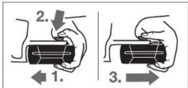
Akkymythopdi6 wibfapy:
- Akymyrratopodbes3neKtpKpabylsTytkcbiHaKapcbs4b6aBtta 8acbin(1.) awy nepheciS (2.) 6dpiedacbuaHia.
- Akcymyntopod3bnyneKpcaibnHaaKb3bnCb3bIK KepiHreHueBipapb3a3.(3).
Auy npneepnii 5 xane bacni akymyntopdi tonblk shparhnh.
AkkymyIATOP 3aparany KyHnHKATOpby (B CypTeH KAPaHa)
Akkymytnop 3apdany kyni HnndkKatopbbln 27 yu Kacbln
kapbln DnoDk Akkymytnop 6 3apdany kyni Kcpcerdi.
Kayincidin canapbnaHn 3apdany kyni Cypay Tek nektp
Kpabln ToKtBnOp bhydMyMkn.
26 nephehicabimapadkykepeceTinej (akkymnatorp 1bHapbipHanBocla daMyMKH)5cckyHdAnCohzapIany KNY HNDATOPBb Euei euei.
XapbikDnOblKyaTbI
| Yadjikcij 3x jkacbl | ≥2/3 |
| Yadjikcij 2x jkacbl | ≥1/3 |
| Yadjikcij 1x jkacbl | <1/3 |
| XbinybllkTayh jkacbl 1xjkacbl | Pesebp |
26 Nepheci baKaHHaH coeBip JapbIKJIOJI KaHbaca OHbl aMCTbpy KaKET.
3apdty KeiHne yuXacbn XapbkDnOdbIeKeKti KaHbIn KsCKA yakita EweJI. YU Xacbl Xapbk DnOdu Y3JICk HAca AKKymTnTOp TOnB, aaprtanfah BonadH. AKKymTnTOp BApkTnAPrTnFA5 MNHyTTaOH CoXacbn XapbkDnOtdapbEweJI.
Apaay dnckiciin ophTy/aybictbipy
3Nektpr KpyaBnIbDa 6apBnHykMbctadpaAnbHN AkkymTApOrDbHbUfApaBhJc
Apanay dncckicn OHpaty keshne Koprpa hnn Konran Knilh. Apanay ndnckie TtHreJe kapaakat any kanyi nap.
TeKocbnaaHny HcckaybIbIbHbN TeXHHaBbIb
DpekeTepine cakce KenetIH apanay Wek6pepIn
nanaHbHbI.
Tericteywee6epnepinKoDbipma petiHne nainanahba.
Apanaydncckicii tanday
YcBnBnBnHnDnckInepre WOnyDnOcna nAanany HcyKaynBnBnHnCObHnDa tabya bOna.
Apanay ducckicn any (Acyperin kapaunb3)
3NeKtp KpyaIbI KoarIaTkiBti KoprnyCbHbN δyIpaIk XaRbHa KOnHbN.
UHHnHdEJI6yIaTAY TmecIn 17 BacIn, YcTan TpybHb.
UHnHnBnIb6yFATTYHMmeciIN7apaunHnHnEiOnpHaBnRan6OncarA6a6cbM3.HTnece3NeKTPKpDaiBH 3aKaMMyDMYMKH
- Antb kupnb KINTNEN 19kckbn BHNHTI 24 bypan bocabtBnB,KnckBnB BNHTI 6aBbHbD a bypan bubarpbHb.
- MahtnHKtIK KOParBbI W KaTAMAbHb 10 aPrtKaTpBIn, 6epK YctaHb.
- Kekkih pfahneut 23 xane apanay dncckici 22
unnnndnbe 20 anbbl.
Apanay duckiciin ophary (Acypetin kapaib3)
3NeKtp KpyaIb KaorraTknBkOkrnyCbHnB dyHnPKaHnA KOHNb.
- Apanaydikcicii 22 xanebapn6kety6eunkeptepin Tasaiahba.
MaHTNHKTIK KOPaBbI KaNTAMAbI 10ApTkaTapBnI,6epK YctahJIa.
Apanay dncckin 22 tipek pfaneueh 21 opahbts3. Tcpeidn Kecy barbl (apanay dncckinnei kerpckeHHBafbrbl) MaHNNKtIK KopraBkau KaTmadaaBb10 bafbr KepceKICIMeh Bpnd Bonby Kepek.
KbckBnIphaneHTI 23 opHATIHb3 KHe BcIKCbW BnHTI 24 6barblHaDpyan6ekITH3. KbcKbWpIhaneHTI 21 KHe TipeK pnaeHTI 23 opHaty KyI dypuC bonyuH KaJraAahBaH3. - UHHHJIDJI6yIaTAY TymMeCIN 17 6acBn, YcTAN TybNbA3.
AnbKpHnDnBeknTEN91KbckBnHTI24 6BarbHbHa6ypan6ekitH3.TapBny MOMENT-6-9HM BonyMVKHH,6yONOMENKaHeAaHnBMHEmece 25 BenricinKopraFnnKaNkta73cbkuaanaphaCnA.
UaHdbI Jxane KOHNkapdbI copy
3NeKtp KypaBbHda 6apBbK XMybCtapAn anBbIn aKKyMnTOpDbI WbFapBbHb13.
KopracbH 6o8y, Kei6ip aaraaw copTnapB, MInhepaanap
XaHe Meanapd 6ap Kie6ip MaepnAadpnn HuaH
DcHcaybIbKa3nHbDb 6oynbMyMmKIN. HaHa TIO XaH
HaDbky NtYr naJaianyuBa hmece XaHbHarF
aamAdpAp annepehnnBk peaknnpnnpn Hae/Hemec
TbHc XOanbpHbHn AypnpabH Typyb MyMKH.
Kei6ip WaaTynepi, acipece emeh XaMnat
araawbHbWahB, acipece, aaraBnOeey
KaNlKnKtAPMeH (xPomAT, aafunn Kop4y 3at) bipre
KaneporeHepb60bn cenentepi. AcSectk materpan
TEK KaA MaMaHdpmEn Hcndny Kepe.
- ⅢAHCOPyDHHXorapH deHreHHe Xety yuHc0b
3eKnTp KpyamEn Bipre wacocpBuHTB
GAS 25/GAS 50/GAS 50 M aarw yuH HEmecE
GAS 50 MS Araa xane/Hemec EMHepaBk WauYHIN
naiDanaHbH3.
KymbcopnhbHHkakcbjXeendinyiHeKesKetki3inj3.


OBI_BUCH-3274-001.book Page 163 Wednesday, August 16, 2017 1:53 PM
Kazakua163
AkkymyIaTOp Temnepatypacb 70 ^ C -TanKorapb6oNcA
IeKIpKpArBaAkkymyITopOTnHMaJIb6TeMnepatypda
BommaHbHaEueiD.
3NeKtp KpKaBb 3NeKpoHKnKcbHbN TemNepaTypacHb 6akJbay:
Kb3nJapbKnDnObl28KocBsw/EwipriuTl36aKaHpaYydiKci3KaHaDb:3NkTPTKpyalI3NkTPOHNKAcBHHTEMnepatypac55°C-tan TOMeh HEmce75°C-tanXkoAfpb.
90°C-TanKorapbI TEMpepatypada aektp Kpypanbl 9eKnpOHHaKaBnaiNaidananyTEMpepatypacBbONMAYbHua 6wEJI.
Tepeh 3apd kofany Koprahbicb
Hnn HnDnK kkyMnyrT op Electronic Cell Protection (ECP) apknbI Tepeh aepd KORANTyad KopranfA. AkkynmnyrTop 3apRbKoK Bonca 3neKtp KpAnbl KoPraHbc CXeMaCb ApKnbl Oipinepi: anMbn-canMbn acnAn BackKa K0FaAmaNbI.
Painanhyhckaynapbi
Apa/ny dncKinepiN CoktbIbCuydAn XKaHe cOKkbIaHn KOPfAHI.
3NeKtp KpyaIbIbipKeIKI XaHe KcY BaBtHa DaAafHai T KbiCIMMe H Kpyi3IH3. Tm KAtTb KbiCIm KOH2bIpMaHSH Kbi3MeT KePcTe Mep3IMH aiTapkAiKapTaTb XaHe 3NeKtp KpyaIbIbZakMdBy MyMKH.
Apanayduh ehiimdinirjxhe canacbkeihece apanay
DNCICIHNI KIyMIeHNIuHIe BAIaHbCTb. CoNDkTAKTEK
Etiip KeHbeHNITIKATKH MATEPNAHKApaJIbH apanay
DNCKINEPIH naIaNANBHLH.
Araunbapanay
Apanaay Dnckicn Dpybc Taaydny aafzthyn TypHe JxHe canacba, coaHai ak, 6oiAn HEmece KeJdenEhenJHEN apanayra BainlAnbctBti.
KoJyDEHHeHHe apanay Ke3HnE y3Bn cepinneni KhoKa naa da 60baHai.
EMEHMHIaIIAMIHbIeHcYNHbIKHeTeIHHJIb, COBHbKTAKHEIaOHcPbIINHJyMChIcIteH.
Papannenbti tipek 6apapanay (D cypetin kapaiba)
Papannenbti tipek 11 daaHdama kneri 6oBmEn dan apanaynapbi yzsere acbyyka jane anwemi biipdi koxnakaptara Kcye MyMKHdk Bepedi.
Kocbimwa tipeken6ipreapanay (Ecypetin kapaib3)
YInKeH daHdAmanapdbI hpey XeHe Tsy3XeKTePdi KcE yuHdaHbDamaKaKcbMua TIpek PteIHDe TaKTHb HEmecpeKaHb6BekIyRE 6oAnDb KaHe NckNik TAKaHbTIpeK TaKtAcBmH BiPe KcBIMua TIpeKTi6 BoBImn Kxpr3yre 6oNa.
InreKTeP (FCypetin KapaHb3)
InreTeepkiH 1 KEMERIMEN ENEK KYPANDaCatiba ININ KOORA 6 Bonada. Byy yuH InreTeepkiD 1 KaKET KYE 6 SekiHa.
HIN3Nektp KpandbH apanay Dnckici KeaeDcoK TIOHEN KOPANFAN GONYBHaHaap aydpabHJ3. Xapakat any kanyi bap.
3nektp KypammeK KaTadaa XyMbic icteriH3 kence, Inrekepdi 1 anbH3.
Akkymyntopdb ontainb naidanany typanby hckaynap Akkymyntopdb cyhikbtkrtapdah jxane bilranaa KOPRAH3.
AKyMmIaTOpDn Tk-20°C...50°C TemnePataypay akymbna caKaTaHb3.AKyMmIaTOpDbl KaDa konikte KJI/IbIpaH3.
AkkymyroTIOBbIyKJXeJIeTIyEICITIH KUMcAK, Ia3A JxHKe KXPfAK, liETAKEMH MYKRIIT TaaanaihJa.
JaananaHpe31MHHaTAPbTKAHTKcXApbY kKymnTOpbnEckpireHHKaHe ayBCTbpyKepeTIRI 6bnipeJepi
KokictapbKaetaeHcyypaBHyckaynapbOpbHaiaIb.
TexHHKaIbIK Kytim XaHe KbI3Met
KbI3MeT KepcTeY KHe Ta3anay
AkkymnTopbl3eKtp Kypammen Ke3 KeRhen XymbCTapblbMbcanbl, OPHATy, K13MET KcPcTcy, T.6.)Bactay anbHna, Coohm-ak, 3KeTp Kpyanbl TaCbMnayJxane CkayTKe3Hne BwHapBbI3. KeanehCOK KcObFnaHApKapat any Kayni bap.
DuscH xae cemHl iety uiy hneKtp Kypammen Jeeketnd Teciki raa cytba.
MaHTHNTK KoprAaBn KaTama aepKaaHaepKIN Ko3rAnyb
Kae03 03BtHeNaeKbNyBkePcK. CoDbkTnAH MaTHNKTIK
KoprAaBn KaTama aHaHaLacBnaHyBaMyAkTy ApKaaH Ta3a
YctHa3n. KhCbnFaI ayamen npye Hemece Klnlak
KeMERImn HaBnKa Hee XoKnapApn KeTipJi3.
KaabHbKoapanayDmcKinepin KblkbncBc3 MyaHbH KykaKaabTbeMekybnKopFayraBonad. Apanay anbHaNMyaHda keripH3, EHTKEHIe KepiKardaaAraataDaKTap naa Bonad.
Xyaderei shaibep HEMeCE KENIMHIN KANbKtApBc Kecy canacbHa acep etdi. CoNbKtAn Tn nnndanhyd an KeHH apany DnckineepH Taaanahs.
TybHybIra KbI3MeT KepcTeY XHe naIdAnany KehecteI
Kb3MeT KepcTeY We6epXnAbacb 0hImdi XeHDey XaHe KYIy, CmDai kKocankBolNeWKeTp npAynCypakTApA.Kayan bepeiKaKeTI Ch3Banap MeKocankBolNeWKeTp npAyn AkapnataMbHa MeKeHkAnd TaBac3:
www.bosch-pt.com
Kehec 6epuyi Bosch k3metkepepi OHMI Naiyanaayxane OanapbKockanb bennwckepi typanb Cypaktmbfa TnHkA Kyaayan 6epdi.
CkpAtpKoKIO KHeHKeOcAKnBb6beueKeTpe TancUpScBepy Kz3HdE MInDTeTI Typde EHHIMIN 3ayIITbK TaTKaTHuaCbHdAr b10-cAnbH OHMOMHIN Ks3BaHb3.
OdipuyiTuanTapbI MeH HopMaIapbIHHcKaTanyBMeH
3nKpKpAaHKeJXeHKeNkIJI Kp3MeT KcpCETy
bApbIK MmEkeTep aMyBaHdaTeK "Poept Boi"
ΦpMauBHK HeMece ABToP3aHaunFaH Ka3MeT KcpCETy
opTaBkTapuHdaOpbHaDanaDu.


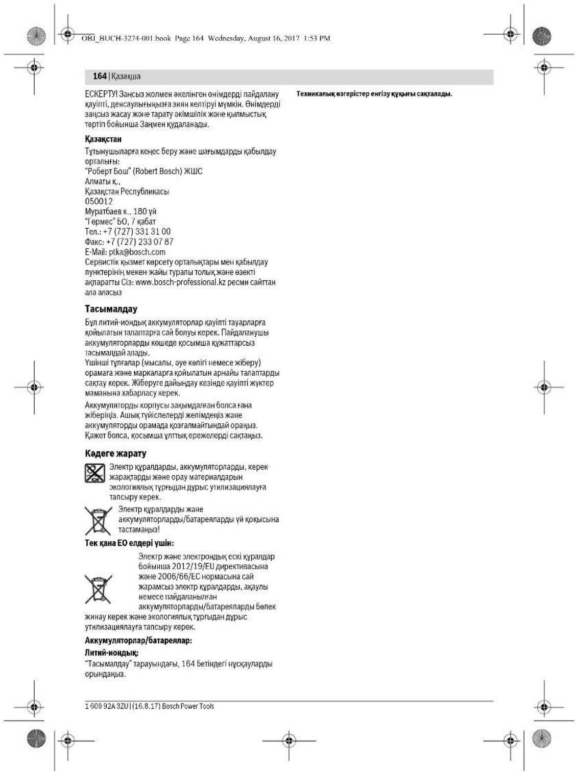
Romana 165
Româna
Instruiuni privind siguranta si protectia muncii
OBI_BUCH-3274-001.book Page 168 Wednesday, August 16, 2017 1:53 PM
168 | Romanà
OBI_BUCH-3274-001.book Page 172 Wednesday, August 16, 2017 1:53 PM
172 | Romanà
OncanHe Ha npOyKTa H Bb3MOXHOCTHTe My

Pnoctette BHHMaTeHbBChKu ykaaHaHa. Hecn3aBHeToHa nIpHBeDEnHtne no-dolny ykaaHaHa MOKeJa daBoDee ToTOKbUyad, NoXaAp WmN TeKxH TcBAMn.
Mon,OTbOpete pa3rBbauata ce KopHua cΦnHyptne H,doKaTOyETepe bKOBoDCTBOTo 3AekCnloTaun, nOCTabeTe OTBOpena.
PpeHa3HaueHHe Ha eNeKTPoHHCTpyMeHa
EneKtpOnHCTpyMeHTe npedHa3aHcH 3a pa3pa3BaHe Ha dpBcHn HATEpHAn IO npaba IINHH, NepENHkYrNHO Hn CbC KcOcBAHe. C NOxOdAun PceKeuI INCTOBe MOrTa da 6bDaat Pa3pa3BaHN TbKoKctehnn Detan OTUBETNH MetaHn Hapn. npOfnHn.
He ce donycka pa3pa3baheTo Ha cepHm MeTAnH.
H306pa3eHH enMeHTH
MoeHepaHeta H enemEnHrte H eneKTPOnHcTpyMeHa cOthACA Do hno6paekHenHrta H cTnpeHnC cDfHyptre.
1 Kyka 3a OKaBaHe Ha KOJAN
2BnOKHPOBKaHaIyCKOBnIpeKbCBA
3Пусковпpeквсан
4PbKoXBaKa(N30nnpaHaNOBbpxHcT3aXbaaHe)
5 Ocbo60kdaabaun 6ytoHn 3aakymnyatopHata 6atepe
6 Akymynatopha batepna
7IpepaenaeH KoxyX
8Ioc3apepyinpaHeHaIapnHPOOKaehnIpEJa3eKoKxyX
9OCHOBHannoua
10単nnpnookayenipednaeHkoxyx
11Onopa3a ycnopeHNO BDOHe
12MapKHPOBKaHa cpe3a 0^
13MapKHPoBkaHa cpe3a 45^
14 Bvntc Kpnunara rnaBa 3a onopata 3a ycnopedHO BODEHE
15 BnHT C KPMHATA TnBa 3a IpeBapHeNHO YCTAHOBABe HA HAcNOHa Hcpeea
16 Ckana 3a H3MepBaHe Ha bfbna Ha CKoCBAHe
17 ByToH 3a 6nKpAne Ha Bana
18 Cno MaTateHnPaBkoXBaTKa (V3oNipHaNoBbpxHOCT3a 3axBaUaHe)
19 WectOteHeHKnIO
20 BaHa enektpoHHcptymenta
21Lehtrhoaafnaneue
22LpKpyIepenDnck
23 3actonopbaaФnaheu
24 3actonopBaW BnH T C Waa6a
25 MapkpobBkn Ha npedna3nHKOxyx
26 Bytoh 3a nokaaba He cTeenentHa 3apeeHoc H akyMnyatopnata 6atepna
27 INHkKatOp 3a CbCToAHHeTo Ha akyMnyaToPHaTa6aTepeHn


BmIarpckn117
28 CBeToDnOd 3aTeMnepaTpHnKoTHpn
29 Ckana 3a 0uHTaHe Ha bIbOuHnHa Hcpe3a
3aTioonpBraHbIoo3JIpeBaPnIeHPOpyIpuHaHE 3bIb6OuyHnHa HBApBaHe
31 DboKa Cko6n 3a 3acto npBaHa
32 3actonopBbH BHT3a aadantrep3a npaxoynahe
33 Aanrpe 3a npaxoynahe
34 MapkyuHaacnpaunHnHa ypeDaa
*360643eHneHa FyHpyrHe O HmCnHHe NpOHHInHnHnPcOcbHnHe Ha BkNHOeHb C stAaDpTHata OkOMPiKtOBKa hya ypeJa. HsuePaNteHN CmCNb K an HmOHnHnHHe nPcHnOCobNe HMOKeTe Da HAMeRHe CbOTBeTHo B Katanora Hh 3a DOnHHn HnPHncOcbHnHn
TexHmueckn daHHN
| Рын每人 БалкхулгКС 36 V-LI | ||
| КаллOKжEN HOMER | 3601 F73... | |
| Номнанно наразець Сборост Ha вретен Ha прадан Ф�ор Мамс.ДыбочиHa срета -при Нakон 0° | V=36 | |
| min | 4000 | |
| mm | 54 | |
| mm | 38 | |
| Балокаре Ha вара Ралу Мамс.ДыбочиHa ошочи Мамс.ДебелниHa талото Ha диска ДебелниHa талото Ha диска Малк.ДебелниHa заю Мамс.ДебелниHa орд; Салдога Мамс.ДебелниHa орд; Салдога Мамс.ДебелниHa орд; Салдога Мамс.ДебелниHa орд; Салдога Мамс.ДебелниHa орд; Салдога Мамс.ДебелниHa орд; Салдога Мамс.DебелниHa орд; Салдога Мамс.ДебелниHa орд; Салдога Мамс.ДебелниHa орд; Салдога Мамс.ДебелниHa орд; Салдога Мамс.ДебелниHa орд; Салдога Мамс.ДебелниHa oрд; Салдога Мамс.ДебелниHa oрд; Салдога Мамс.ДебELниHa oрд; Салдога Мамс.ДебELниHa oрд; Салдога Мамс.ДебELниHa oрд; Салдога Мамс.ДебELниHa oрд; Салдога Мамс.ДебELниHa oрд; Салдога Мамс.ДебELниHa oрd; Салдога Мамс.ДебELниHa oрd; Салдога Мамс.ДебELниHa oрd; Салдога Мамс.ДебELниHa oрd; Салдога Мамс.ДебELниHa oрd; Салдога Мамс.ДебELниHa oрd; Салдergа Мамс.ДебELниHa oрd; Салдergа Мамс.ДебELниHa oрd; Салдergа Мамс.ДебELниHa oрd; Салдergа Мамс.ДебELниHa oрd; Салдergа Мамс.ДебELниHa oрd; Салдergа МамС.ДебELниHa oрd; Салдergа МамС.ДебELниHa oрd; Салдergа МамС.ДебELниHa oрd; Салдergа МамС.ДебELниHa oрd; Салдergа МамС.ДебELниHa oрd; Салдergа МамС.ДебEL nor Салдergа МамС.ДебEL nor Салдergа МамС.ДебEL nor Салдergа МамС.ДебEL nor Салдergа МамС.ДебEL nor Салдergа МамС.ДебEL nor Салдergа МамС.ДебEL nor Салдergа МамС. Салдergа МамС. Салдergа МамС. Салдergа МамС. Салдergа МамС. Салдergа МамС. Салдergа МамС. Салдergа МамС. Салдergа МамС. Салдergа МамС. Салдergа МамС Салдergа МамС Салдergа МамС Салдergа МамС Салдergа МамС Салдergа МамС Салдergа МамС Салдergа МамС Салдergа МамС Салдergа МамС Салдergа МамС | 12 | |
D 3abCHMocOT hONoBaHata akMynatoPb a batepH
"orpaHnueHa npohAboHntHoHc npH TempeParpy<0°C
HhOpMaun3a H3MbYBaH Wym N Bn6paun
CTOHOCHTHE HAIINbBAHNAIyM Ca onpeDENH CbIaNHO EN60745-2.5
PabHHuetoAhaReheHepnauHHyM o6MHHOBeH e:paBHue H3aBkyBOTo HanaHae 98 dB(A);MoOHCT Ha 3byaK 109dB(A).HeonpepehOeK=1.5dB
IpeepncBaeTOnDJIHHTENMeRk3a nppePnaBaHe ha paboTeHN C eNEKTOPHCTpyMeHTA OT BbEeCTBHeTo Ha BbOPaHIne, HApHmPEr:TexHHueCKO bcNyXbaHe Ha eNEKTOPHCTpyMeHTa N pABOTHe HcPTpyMeHTH, NoDJIbOxHa He h bIeTE ToTNH, IeNEcBo6pa3Ha oprAHsauHa ha pabOTHe CTbNN.
MOnThIpaHc
3apexdahe Ha akymyataPgha 6aTepe
HAnon3BaIe cAmO HnKoeOT 3apAHHTe YcTPOHCTBA, COUoCHN HA CTPNAHuaC aDONBHNHTENHNT NPHCNOCbHNN. CAmToTe33 3apAHHy YcTPOHCTBA CaNoXoJr 3a 3nn30AN3BaaH Bb BAaIN eEnkPoTHCNPTyMeH NTBEHOHNA kAynMnatOPHa6atePnH.
YmbTbAe: AkymyIaTOPHATA bATEPHI CE DOCTABI CACTNUHO 3apeHedA.3daDcSTHTHEIbIHINRAKANAHTET HA kymyTAbOPHATA bATEPHI, npdeIbTBoTO IaONL3BAHe r aapeHedE DOKpAH B3aIPNDHTO YcPTOBCTBO.
InTeBO HoHNATA akymnatoPbHa 6aTepeHn MoKe da bSe da 3apeJaHn no BCKnO BpMe, Be3 ToBa da cKpaAaBda BBrot- pAnHOCTTn. IpeKcBAeH aHaepaJeHeto CToHe He BPeHn. InTeBO-HoHNATA akymnatoPbHa 6aTepeHn e3auHn cpeuY mbHo pa3peJdane o TeneKtPOHHa MOnyn ,Electronic Cell Protection (ECP) ,PiN pa3peJDa H a KaymnatoPbHa 6aTepeHn eneKtPOHHcTpyMeHT c KeKlNoaB o nppeNaeaen peKbCBAe: Pa0ToTHHn HcTpyMeT Cmnpa Da cBe DNHX.
CnepaTOMaTHUHOToK3KNHOVAHe Hae ENEKTPOHNCTPYMeHTA He npOdbNkBaBte Da HATNCKATE NcKOBnPneKbCBa. AkyMynatopHata BateRn Moe da bDe nopeDeha.
CnbaBte yka3aHnra 3a 6paKaYBaHe.


178|Бынгарский
H3BaXdAne Ha aKymnataTophata 6aTepeHn
Akymyatopnha 6 c e dte CENH na 3axbaaune, KOeTO TpBaDa na pIepoBbPn taIaHeTo I npH aTHcKaNe IHO HEBHHNHa H bTyOHa 3a OcbOpBXdBaHa Ie Akymyatopnha BatePn 5. Korato Akymyatopnha BatePn e NoctabeHa b EneKtponHcptpyMeHa, Ce npDbPxa B HyhNata no3Hnra O tPVyHKHa
3aIbKaJaHaHaakymnatoPnHa6aTePn6:
- PnHtCHETe akymyatopHTa7 batepyrKaM kpaKaHa nEeKTOHNCTPymETA (1.) nEOHBpEMEHHO HATCHETe OCBOXbDaaBuaH yBuTH 5 (2.).
- N3b2p1a4te AkyMAtOpHATA6ePrrO tEENKPOHNCTyPmHaT, KOkTO cE NOAKE YCepBHeA HNbI (3).
HaTHCNHTeOCBO6OxDaaaHb BYTOH 5oue BeHNbK H3- DpnaTe akymynatopnata 6atepn.
CBetHHHeH HnHkAtoP3a CbctoHMeHO HaakymyAtoPHa- ta 6atepHra (BHXTeΦHr.B)
Tpne 3eene HcBtoJIOda 27 nokazbAT cTeeneHa h3apeHocH ta kymnatoTHa batepn6. Nopadn cbobpaKeHHa 3a 6e0anochct npoebpKaHa h cTeeneHa h3apeHocH ta kymnatoTHa batepnMoKe Da ce NbbpuBa CAmO Karato enkTPOHNCTpyMeHbTe BNOKOH.
HaTCHETebyToHa26,3aBaBmTeCTeHHTaHa3apeHoeHTA kAcymyIaropHATA BaePnra(Bb3MOxHOeCbIOH N pINr H3Ba- dHeA kMyIaropHAr BaePnra).CBeTOHIOHrTeYrACbAT BO-MATNUO CNEpNp6n.5 cekynH.
CbetodnoKanaunrT
| Helenpbchato CBETHE 3 x 3eNeho | ≥2/3 |
| Helenpbchato CBETHE 2 x 3eNeho | ≥1/3 |
| Helenpbchato CBETHE 1 x 3eNeho | <1/3 |
| Mharta aCbETHnHa 1 x 3eNeha | pe3epBa |
AOKIeHdHNTCKHeHa bYbTHo26 He cBETN HtO eDINH CBeTOnIO, AkyMnATopHata bTePn e NOBpeHena H TpRbBa da bE de 3aMeCHHeA.
No BpeMa HApceoea Haapezdahe Tprte 3eennHcBcTeOnDa cebTbAT NoCnEoBaTeHNo HcNtToBaYcRaT. Korato Tprte 3eennHcBcTeOnDa aaoVohTa da CBeTRH hEnpeRb ChaTo, acymynatopHataBatePra 3eapaHepn ToTae 3eennHcBcTeOnDa yTacRaT.
IocTabaHe/cmHaHa pexeunn Dnck
PepnHa3BpBuBaTe KAKBTo Ha eHcHcTHNo eKekTPOHcTpyMeHTA demOHTHpaTe AkyMynaTOphata 6atepn.
PnMoTHnpAHeToHaUkpKpyRpnHnDckpa6oTe c npedn3nnpKbAnHH. PnpOJnoDpoKpKpyRpnHnDck cbJeCTByBaOnACHT Da CE HapAHNTe.
Hnon3BaTte cmo pexeun dNckOBe, KOHO CTbETCTBAT Ha DaHHTE, NOcOeHN H TOBA PbKOBOCTBO 3a eKCN0AutaYn.
B HnKaIb CnyaHne H3n0n3BaTae 6ap3nBHNmckoBe.
H36opHaunpKynnHnDnck
O63op Ha npenopbYbaHInTe pexeun DnCKOBe MOKeTe DaHa MepeTBe B Kpa HA TOBa pbKOBOCTBO 3a EKcNIOaTuIN.
DemontpaHa npexeunHdck (BHXTe pnr. A)
Hai-dobpe e npn CmraHa h auKpyuynrDnck da nocbatne enektpnohtpymeta HnerHan Ha YenHata cTpaHa H enektpoBnAriTeiHa.
HaHcHe H3aPbXte ByToHa 3a BnKpaHe H a Bana 17.
HATNCKAITE 6YTOHa 36NOKHPAe Ha BAN7 17cmoKATO bIPTEHETO HaN BcPNOHbAMhHO. BrpOHBEN CNYAU ENIEKTPOHNCTPMEHTB MOKE DA B6He NOBpeED.
C IeCTOCTENHNI KNOU 19 P3aBHTte aactonopBaAunna BHTN 24 Kato bTbTTme B Nocokata O
- 3aBpTe Tae wapHnPHN npedna3eH KOxYX 10 HaaJr to 3adpbXte.
-Демонт��дуэт actonopobuaцmaфанeeц 23ичркгар
НИДСК 22ОТ BAHA NGEKTOHCTDYMETA 20.
MOHTIPAHe Ha pexeunu Dnck (BHXTe omr. A)
Hai-do6pe e npn CMRAHa NaIcKpyNPHIA DICKaNoCTABITE eKTEKPOINCHPTyMeHTA nEHN HAI NENHATA CTpHA HAI eKTEKPODINHATeTCA.
-ПОНТЕТЕРЕХESHAДNCK22HCSNUDETAINI.KONTO SEМОNTHAPTE.
- 3aBpTeIe IapHnPHINI PnpIaIaIeN KOxyX 10 HaaIaIIO 3aDpyKx.
Iocbeteu npkynpa 22 Ha eTpoBuaa Hnaneu 21. Nocokata Ha pnaahe HA 3b6nE (O3haeHa cbc cTePka Ha npkynpa) nCTpeKATA aNocokata HA BpTeHHe HA uapHnO kauenrrnpedn3eH KOkyx 10 TpaBa da cbNa-dat.
- NocTabete 3actonopraaunn phaneue 23 n HABNTE BHHITA 24 KATO BO BYTME IN NOCOKATA BHHMABAJTE ONOPHINT Phaneue 21 NactonopraaunnHT Phaneue 23 da CBAeB3NJ npabnHIO B NO3HNJNT CN.
HaHcHeTe H3aDpBxTe ByToHa 3a bNoKnPaHe Ha Bana 17.
C JIeCTOCTEHNNKIOU 19 aTERHTE 3aTOnOPRAauHnBHTN24 KATO FO BPTNE B NOCOKATA 3aTRAAHNTMOMEH TpRbBaJa6Be6-9Nm,TOBA cBOTBETcBA Ha 3aTHARHe HpaBbAiooF 06obopOTN3 deneHHa HMAPKHOkata 25Ha npJtnaahnn KOKyX7.
CnCTema 3a npaxoynaBnE
PnepdHa3bpuBateKaKBHToHa deeHHCTNo eNekTOPOHCTpyMeNTaDeMOHTnpaHTe AkymyTAOPHTa 6atepe.
Ppaxobe,OtdenrnnCe npnO6pa0bTaBHeTo Ha MaTepeHAni HcKaCbDpaKAnu OIOBO 6oN, HRAOK BMDBe OBaBcEneHa, MHepeHAni MeTaN MoTat DaBdpat OaCNs 3a 3dpabeTc. KohtakbTdo Kokata HmBdWbAeHTo Ha TaKKBa Tpaxobe


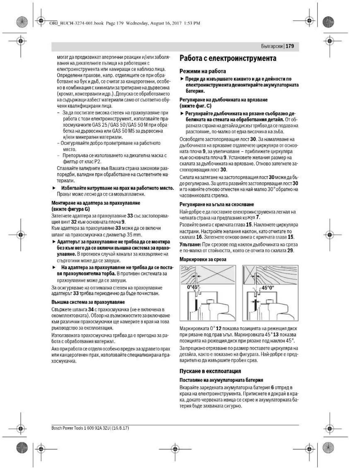

OBI_BUCH-3274-001.book Page 181 Wednesday, August 16, 2017 1:53 PM
MaKeJIOHcKN181
IopdbpxaHeHcepbH3
PoaBpKaHe H nouHCTBaHc
Pnepi da H3bpuBATE KAKBTO M da e JeHcHTN no enekTPOHCHTPMaTE (hanp. TeKHeuCKo 6cbNyKaBAe, CMHa naPabOTTHcHcPTMEn T.n.). KOATo rTo pTaHCNoPTnPate mHn CbXpaHbAte, demOHtnpaIte AkymnatopHata bateRn. CbuECTByBa onaCHOCT ON ha paHbRAhe npn 3aedtCBaHe naYcKOBnPipekbCBANo HEHNHMHe.
3a da paobotnte Kauetcbeno H 6e0nacno, noDdbpxkai Te enektpoHnctpymeha n BeHTnauhoHHNte OTBOPH NCHTH.
UAPHINHPNHTPnepna3ENKoxyTPRbBA da MoKe BHNaHn Da ceBpTHCBO6DHO n Da ce3BaPRAcMocTOrTHNo.3aToba BHARn NOIpaJBeAte 3OHaT aKOIO UAPHINHPNPTPnepna3EN KOKOxy CBO6DHO n HnCTaOTpAHBeIe npax hCBptroHHn CnpOyXBaHE CbC rCTeH Bb3dyx HnC MEKAyETKA.
PeKeHHI DnCKOBe 63 NOBbPxHcTHO NOKPITHE MOraT Da 6- dAT CMA3BAHN EKo MCAHNNHO MACNo, HecBbDxAuao KHCENHH.3aJa npedotBparntte KzauanBaHETo Ha bpbTO, ppeHn paap3BAe NoHcHTCBaTe MaHHINOTO MAnO.
Otnaraheto Hc moTaONHnIeNHOyTuKAnNopeJeeuHIND NCK BNOABA KaeCTBOHOa Cpe3a.3aIOBAIOuHCTBaTe DnKoBete BEnHara cneynOTpeBA.
CepBn3 n TexHnueckn CbBeTH
OTOBOPHnHa bblpOCHTE cHOTHOChPemOHa HIOIpaBkKaTa HA BauHH npOdyKT MOKETe Da NIOyHTe OT HAJIIN CEPBb3EN OTdE. MoTAKHH qTePHXn HINFOPMAuHa 3a pe3epBHN aC T hMOKETe DA HAMEPICT CSbIO HA aDpeC:
www.bosch-pt.com
ExmbT ha 501 ta 3x TaeHHueckn ChbTeH pnpHIOXeHNH iE OTOBOPHC yOBOONCTBHe BA HbIPOPte Bn OTHoCHO HAINTE pOQyDHTN aOBtBNHENTHNE PpNCNoCObENHa 33TIX.
MOn, npN bIpOnc H npN npbBaHe Na pEeepBn Nacth BN HnN noocBaVe10-ncPpeHn KatanOKeH NOpE, HnNCaH H naTabenKataHa ypeDa.
BbIrapra
Robert Bosch SRL
Service scule electrice
Strada Horia Macelariu Nr. 30-34, sector 1
013937 Bucuresti, Romania
Ten.: +359(0)700 13667 (Быларскн)
ΦaKc: +40 212 331 313
Email:BoschServiceCenterBG@ro.bosch.com
www.bosch-pt.com/bg/bg/
TpaHcnpOpTnPaHe
BKnVohneHtte B oKOMNkTeKoBATA. NHTHeBO-0OHNN AkyMnyTta
ponH batePnBa C aOBXBata Ha N3CKBaHHaTHa H aOpHMnBH
HNTe JDOxMyEnTH, KACAeUH nPiOyJTK c NOBIIHue OAnCHOT.
AkyMnyATopHnTE batePnMorat Da SeBd TpaHcNIOptpAHn
OT npTe6bHtEN Ha NpBbHnMeCTa 6e3 DoIbTHInEHN p3a
peWHTHn.
IIpI pTaNcnpnTbAeOHT eTnCTaHnn (HaNp npBv3zUyW nTAPCNOPN NIN NON3aBe h Kypnepckc cynYnn) HMa CnueP
JHNN 3NCKBHAHKB MOnAKOBAHETHO 6O3OHVAHBOHTHO.
3a cIeIe Ce KcONCYPnAte H CcEepNT B cStbTeHATA O bIaCT.
HINPAIATy Ae kMyIATOPHN B aTePEN CMAO Ako KOpNCTbM HE N oBpeHEn. NaIOHPaIe OTKPNTH KOJIANTKH KNEMH C ne
NAI INHn H ONAKOBaTE Ae kMyIATOPHN B aTePEN Taka, ye
DA He MOrTa Dc HmEeCTBaT B OANOKBKA t CH.
Molna, cnataaBte cbuo N dobnHnHtenHH NaHOnHAnHH npednHcAnHH.
Бракунан

EnIpHnHcTpymHntte,akymyIatopHnTe batepn H nOtnHnHTenHnTe npncnCobBnHN TpRbAda bBnDat npedabHa 3a onoNtBOpBaHe Ha cbDbPxAuHTe Ce BTRX CypOBHH.

HnE3XbPnBnIeEneKTPOnHcPTpyMeHTN hAkyMynatopHH mO6hKnHOBeHN Batepnn npH 6bTb0BteOTnadzui?
CaMo 3a CtpaHH OT EC:
CbrnacHo Ebponeecka HnepeKTHBa
2012/19/EC OTHOCHO HANANA OTyNORPe6A eNEKtpnuecka HENKIPONHAn apataypHa cnBtnacho EeponeeKa dupeKtBa
2006/66/EO obHKOBENH n AkymunatopnHbatepeHH, KOHTI He MoRATJa c HINOLBAA
nOBeue, TpRb6Ba cIe cb6hprat OJENHOa b6b4at noOanarAHn H aNoXoHua pReap0kTa 3a oNIO3TOBpaBAHe Ha cb7bPjKaaJIte CE bTAX cyPOBHN.
AkymynaTOPHHHnO6hKHOBeHH 6aTePHH:
Li-Ion:
Moln,cna3aHte yka3aHHraTbpa3dien,TpaHCnpinpaNe",ctpaHnua 183
PipabaTa 3a MmMeHeHH 3ana3eHN.
MakeOhcN
Бe3бeнocнHaNoMeHH
OnuHTH HANOMeHH 3a 6e36eHNOCT 3a enEeKTPnHHTe anapatH

INPDEYNIPDEYBAHBe HIOPOHTAReIeCNCTE HANOHEMN IYNATCTB3a BA
63e9dnoct. TpeuKHTHe nactaHn KaKo pe3yntat od HnepnpKByBaHe do 63e9duChnTe HanoMeHHn HnyatCTBA Mooke da npEi3BbKaAT eEnkTPhueYdpak INnn TEKKN NOpEBn.
347aaybaTte Hn 6e6bDnoCHHTe NANOEMH N yNATCTBa 3a KOPKTHEt H 3a BO kHHHa.
IOMOT eNEKTPHEN anat" BO HANOMEHnTE 3a 6e36eHnOCT CE ODECyBa H ENKTPHNH anapatn WTO KOPMCST CTpyjA (co Ctpyen KaBen) H eNkTPHNH anapatn WTO KOPMCST BATEPN (6e3 CTpyen KaBen).
Bosch Power Tools 1609 92A 3ZU(16.8.17)


OBJ_BUCH-3274-001.book Page 182 Wednesday, August 16, 2017 1:53 PM
182|MaKeJOhcKn
Be36e1nOCT Ha pa6oTHOTo MeCTO
PabotHmN pOCTOP cEOKaII HeK aBHe MCT H o6pO ocBteNH. HeypeINOT mI HeoCBeTN paBoTeH npOCTOP MOKe DA JOpBeD o HepeKei.
He pabotete co enektpnHnot anapat Bo OKoHna Kade NOCTOH ONACHOT OD EKCNIO3Ha, Kaede HMA 3anaHBN TeuHOtH, rac HIN npaHna. EIneKTPnuHHTe anapath Co3dBaat NcKpH, KOHNMOE da Jaaanata npaTbTA HIN napeata.
- Dpxkete Hn deata H npyrrte Nnua noadaneky 3a Bpeme HA konpehcteHa neneKTHHNOATAP,IOKOJky HEUTo Bn rno nonpehy BNHMMAHHe,MOKeJa ja kry6BnTe KOHTpona Nahd yepoT.
EnektpnHa 6e36eHnoct
PnKnyokOT Ha nEeKTPnHOT anapat MOpa da Orobaba HA npKnkyokOT Bo SdnHata Do3Ha. PnKnyokOT Bo HNkoj Cnyuje He Cmee Da ce MeHyBa. Heynotpe6ybaJte pneKnyBaCu o daanTp 3aeHDo co 3a3emJHnOEt EKeTnHepAnAP. HEmeHyBaHTo Ha npKnyHbAOT Ho COoBETNHTE SdnH Do3Hr HoHamayBaat PnHKOT OeIeKTPnueYyad.
H36eHybajte h3n4KKn KOnrAaTc 3a3emJeHHe NoBpHHNa He8kN, padjAtopn, UnOpet H pHKnepn. IocToI stroEmnH3NK OJ eEnKtPhuey HyaP,doNOKkny BaWeto Teno e 3a3mJeHo.
EneKTPNHNrte anapatn DpKrrte HnoaneKy od odoj n Blra. HaeIeryBaHTo h Oba Bo eEneKTPNHOT anapatro TOrOeMyBa PnHKOT od EneKTPNCHyDAP.
He ro Kopnctme Kaenot 3a dpyra Hameha, 3a da ro HCNTe enekTPhHnOnatap, 3a da ro 3akaneHTnn Ro aBneene pNknnyokOT SDnHATAo3Ha. JdoKeTe ro Kaenot noHaCTpHa oTDonHnHa, MaCNo, octPr paobOBn Nn NOBbXhHTe KOMNOENTn HA ypeDor. OiTeEHNt Hn CBtKan Kaenot r 0rnoemyBa Pn3NKOT 3a enekTPhHnOyap.
KoKcOeKtHnHnT aapat paoHTHe Ha otBpeHo, KopHCTe cama npOdoJKeH KaBeIto e nOroDhen 3a KOpHCTeHa HauBDOpeHnnpocTop. KopHCTeHbTo HaaCooBTeH npOdoJKeH KaBeIha otBpeHo To HAMAJyBa Pn3NkOT oEkeTpHHen yIap.
Dokonky Kopnchtbeto Ha enektpnHnot anapat Bo BnaXhna OKONHHe H MoKe Da Ce N36BeHne, Kopnchtete 3aunTHen ypeo co dHepenHnHa cTpya. Yotnp6bata Ha a3wnTHmOyepo co dHepenHnJaHa cTpya ro HamaNyBa pN3KOT od eNekTPuHyen ydp.
Be36eDnoctHaHnua
BdTepe BnHMeTENKako paoTne H a3yMHO KOpHeCTe ro eNtPHNHT anapat. He KOpHeCTe eNtPHNHT anapatn, DOKOKNY CTe yOMPHN HIN NOB BnJIaHHe NbIpa, AnkOxON HIN NEKOBH. EEDH MoMeHT HnEBHMnHE npnYIpoc6bata Ha eNtPHNHTo anapat MOKeJ daobedeNo cepno3HN NoPbeRn
Hocete 3aathTHNa onpema Hcekoraah hocete 3aathTHn Ochna, HocheIto Ha3aathTHNa HcakaoHa np.MacKa 3a npBa, obyBkn 3a aathTHOnd.nHf3a6b, 3aathTHeN shMe
INH3AHTHTA 3a CNYXOT,BO 3aBCHOCT Od BHOTI INPMHeTATA HneKTPnHnOT anapat,TO HAmanyBa PnHKOT NOpBNep.
H3eHyBaJte HeKoHTponHpAno KOpHCTeBe Ha anapatHe. OChrypete Ce,NeA eKnLyuH eEnkTpuHnot Anapat, nped Ra o npknPyuHtHe HnOlyBaBe co cTpyJa u/HnHa 6aTeepJa, nped Da ro Zemete nn HocHe. JokOnky pNn HocSeIbTo HA anapatCt, Ro Tc BlanBnPrcTod HA npeknYBaHOT nHn CTe Ro npknPyuHne ypeDto Ddoeka e BKnVyeh Ha nOlyBaBe co CTo pyJa, OB MaOkJa a PnpE3BnKa HecpeKa.
3aepybahe, npd afo Bcnyuhte eekptnHnHOT anapat. Jokonky hma atan klyu BO hekoj odienobnTE Hyejeot wto ce bprat, oba moxe da doabege no nobpebr.
H36herhyae abhopmaHNO dpKebe ha tenoto. 3aChaTeHe BO Chrypha nOnoXbHa NoctOJaHO dpKeTe paMhotexa.Ha ToJ NaHn Ke Moke NdoBo Da ro KOHTpOInPate eneKtpuHnOT anapat Bo HeOeKyBaHN CHTuAHH.
Hocete coodbetna obneka. He hocete shpoka obneka nHHa HAKIT. TprHete ja KOCATA, obNeKATA npakabHHTe noaneky o nnobnKHTe denOBN. Ncchata obneka, HAKITOT HIN dnrrata KOCA MOKE da CE 3adpatat od NOBHNKHTE denOBN.
10okny tpe6a da ce HCTannpaaTypei3a BmkyBaeBn pape,OCHyperte Ce deKa Tne npBAHHo ce nPKlyueHHn pHKnlaHO ce KopHctat. KopHCTeHTo HA BmkyBau 3a npHB He ja HamaNyBa onachOcta oJ npAB.
KopHebe HpaKyBaBe co eNeKtpnHnOtnapat
Ro npeonotabaybajeypeo.Kopctete ro cooDBHTHNOE neKTPuHNe anapar 3a Bauata pabaota. Co cooDBETHNOt ENEKTPrHn e anapar Ke paboTne noDobpo H NoCNIpyHPO BO 3a daeneHOTOMeH N a pabaota.
HeKOpHcTeRo enEeKTPuHnOT anapat,doKoKny HMa DepeKTeN ppeKHyBaA.AnapatoK oJIOBeKe He MoKe Ja ca BkTuHmH NckTuHy,Ja 3aRpo3yaBbe3eDiocta H Mopa da Ce nonPabai.
H3aenee ro npnkyokot od 5nHa n03a Hnn H3aede ja 6atepnhjata, nped da r h cmehnte NOCTABKHe HAypeD, naH 3aemeHHe NENbE Hn Da ro TPRHete HacTPaHa ypeD. Obme MepKHa npdyeBahe ro cnpeyBaat HeBHNMaTeHHOT cTAP H aEnkTPHNHTypeD.
YuBaJte Rn noJaNeKy OJ dOpaTOn Ha Dea
eneKtPrHnHTe anapath KO He rN KOPcHTHe. OObj
yped e Cme Da fo KOPcTAT HE nAua KUo He ce
3anaO3aHEn CO Hero Hnn HE rN HMaat npouHTAO Obne
ynarCTBa. EneKtPrHnHTe anapath Ce onaHn,doKoNkYrN
KOPcTAT HeNCKYCSHH NIIa.
OdpxyaBJTe rHrpnKINBO eNEKTPCHHTe anapath. Pnpoepe Taan DnOBHNCTe denobh FyHKUHOHPaat 6ecnPekOpHo Hce Ce3arnabeHH, Daan ce CkPseHHMn OHOTeHN, UTO MOKeJa ja nonpeHf FyHKJHata Ha eNEKTPCHNt anapat. NonpabeT rHouTetHe
1609 92A 3ZU|16.8.17 Bosch Power Tools


MaKeIIOHcKN183
IeBNOB InpE KOpHcTeHo Na ypeOt. MHOry HecpeKHa Cbojata IIHHNa ja IMaAa BO JIoO OJpKByBaHInTe eNEKTPUNH anapatn.
Anatot3acehebeopkybajre to octapn HCT. BHmATEHNO opdyxBAHHTe AJIATn 3a cehybe co octpn paobOB 3a ceHyE NOMANKy ce 3arnabyBaHT n CO HNB nonehc ce paobTH.
Kopnctete H eneepnHne anapath, onepemat, daoatouhe 3a anatte HTH. BO cnohacote co OBA yanatCTBO. nptHO zemete HOr obsohp aobothme yocnbn H dejoHcTaTOpeBa da ce Hbpiu. Kopnctebeto h eneeptnHH anapath3a dpyra ynoTpe6a ocbeh haedeHata MOKe daDobeDe eo onaoch Ctuyau.
KopHebe npakyBaBe Ha 6aTepeHcKnOtnapanat
Batepnhe Tne nonheT H co nnonhau HTO ce npnpopnauHn KncNHyHO 0d npno3bOndenot. Dokonky noonhaQT KOe npnnaoRHe Ha eH eCoobTeHT Bn Batepn, ro KopnCTHe Co aDyTH Batepn, NOCTOn OAnCHOT dONKAp.
3aTOA KpHCTe 6aTePHK Oce pneBdHnHa 3aEeKTPHmHOT anapat. KopHCTeHbOpyr BHD, aTePHM MOKe Da doBepe Do npoBepHn OHnACHT oNnKap.
Heyntope6eHata BatepNia dpxxete ja noaneky cQ kAnenapcnck CnojBvAnKn, KnyeBn, Jxene3nn Napn, KNHNu, upaPabOn HnDpyr MAnh MetanHH npEmTH, UTo MoKeJa npEn3BkAaT npemctyBaBe Ha KOtAKTHTe. KpatOK Cnoj MeYI KOtAKTHTe Ha BatepNjata MoKeJa npEn3BkA hROpeHNu HIn NoXApK.
PnH norpeHNO KOPCTeBHe,MOxE Da HCTeue TeyHOCTaOdaepHjata.136berHybaTe KOHTAc co Hea.DOKONKy CnyauHIOdoJeBOKTACcoTeyHOCTaCMLNAKHEte jaCo BOda.DOKONKY TeHOCtAoJDe BO KOHTAc co OHTeOHTaTeOHCTOgDaePbHjatoMoXeNpEniBhNKKaOXHNHPATAHINH H3ROPTEHNI.
CepBHC
PnonpaKaKATA Ha BauHOT eNEKTPuHAn apat CMee da 6Ike H3BpEHa cMo oD cTpaHa KBAHNHKNyBaH 3tpuey nepcoaH cMo cO kOPHeBeHa opHHNnHpeepnH denOBH. CaMo hToHauHH Ke 6IkeTe cHTpynH BO be3bEdnOCTa H eNEKTPuHnO anapat.
6e36eHOCHN HANOMEH 3a Tpkane3HH
Noctanka Ha ceuehe
ONACHOT:He nocerhybajre co dnaHKnTe BO noneto Ha p6oTa co nHATA NHNCTOT HA HnHTA. Co npyra tapa dpkete ja daononHnHTa Dpka nn KyKHTe HAMOTOP. DoKOnKY CO daBte pAnKH ja dpknte nHATA, HEMa da MoKe da ce NobpeHtE.
He noceraje noi den noto ce o6ba6botya. DOKOKNY 3a7HTHnata xayba e noi dennoto ce o6batobyta, hema da MoKe de Ba nHTTH oN HCTOT 3a hinnata.
IIOdecete jaIaIbOuMHATA Ha ceeHe Ha De6eHHATA HA denot uTo ce o6pa6OyBa. IOn, denot uTo ce
6ob0a3y7bga, Cmee da ce BnHIO nMOANKY od OIOHATA BHCINHA H3aIJIeTc.
DenottoceopabotyaHnKorauHe roDpIXeBO paka HnHn HADHora.TaepcTeTeo denotto ce opabotyaHa ctabenHe npPata.BaHOeJ a3uPCTHTe denotTO ce opabotya,3aJa ja cBeTe Ha MMHHM yonACOHa oTeneCn KOHTAK,3aJIyBaYBaHe HA JIOCTO HA NIIATAI NIN YR6BeHe hCaKOHPiOna.
JpKTe ro eneKTPuHNOT anapat 3a H30nHPaHNTe noBpHNNHa paKaHTe,doKONKY BpuHTe paBoTH Kade anATOT WTO CE BMETHYBA MoKE da HAnDE a CKPHeHH eNEKTPuHN KaBNI. KoTAKTOT co eNEKTPuHN cnPOBQDNHN TcTabA H METANHITE DeNOBN OJ eNEKTPuHN anapat nOJ HANOH N BOHN DO eNEKTPuHN yUdp.
PndoJnnKc0ceee cekoraw yonptpebyaje rpanHmHK Hn arona BODNk. Oba ja nojodpbya npes3HocTa pnpreEe He naHaMaNyBa MoXHoCTa da ce 3aIaNBA NtCTOT HaNlata.
Cekoraa KOpCTeTe NtObTHa 3nNnBa O pApBNHnA rolemnHa n Co oodBeTe h OTbop Ha npHpTaT0 (Ha np. coPomboDen HnPKaneB eOnhKn). JIcHToBte 3a nNna, Ito He OJrObaPaat HA MOHTaKHe TepoBNHa nPiata, Hema Da ceat PAMHO MIOKe daDOBePat do ryBeHe Ha KOHTponata.
Hnkoraahe ynoptpe6ybaTe oWTeTHeHHnnporeuHH nndooukHH npapobOH 3a HCTOT 3a NnIATA. PoioukHTe HIN upaOboHte 3a HCTOT HA nIIATA ce CneUjAnIO KOHCTpyHnA 3a BAIATA nIIa, 3a ONTHMANHa jaAHn Hn paOtoHa 6beDhoCT.
PocneiMHoNOBpAHTHyUdAPn-HcoOdBETNH 6e3eBNOCHN HANOMEH
- NIOBpaTHHOT yUAP e HcHauJeHa peaknHa nopadn
3aKaueyeh, 3aNaBaeHN kIn nOgPeuHNO haocHeN hNCT o
PiHATA, tIoI OoBeYbJ oTo IIN PAHNEKHTOPINHPaHO da
ce noHNthe i aHa n3neSe o denOT oTO ce opabotya Ha
ce npDnBnKBo NPpaeB HA NtEto OT Jo KOPnCTH;
-DOKONKY NtCt HO nIHATA c KeaNN Hn 3aKnABn BO
pe3NtHnIPOeJc, c BkOKNKpa, HmOtOPaTH CnHa jBaPaKa
NtNABo NPpaeB HA NtEto OT Jo KOPnCTH;
-DOKONKY NtCt HO nIHATA c HeBPTn Hn nporeHNO To
HAcOvH Pe3OT HA NtHATA, ZaJIITHe HA 3dAHTA HbNtQo
NtCt HO nIHATA MOKeJa ce 3aKaayat Ha NobpUHHATA Ha
DeIOT To HO cObaOpBTya, pRn tIO NtCtHO HA nIHATA ce
BaHJOn p3NtHnIPOeJn J a PnDhBnKyBa nIHATA BO
npabeCu HA NtEto OT Jo KOPnCTH.
PbOBpaTHHOT yUAP e nOcNeHua OD nORpewHa yUmotpeBa Ha
nIIATA.ToT MoKe Da cCePNHeCo coOpBETNa NpOncNH MepKki, KaKo tIoE to OHNIuaHO NOUY. - Dpxeje ja uBpcto nHATA co DBete dAnHKn H
Hamecete Tn paqete Bo no3nju BO koja Ke moke da
Ja n3dpkhtne nobpaTHa cHna. Cekoraw 3actahyBaJte
6bOu od nHCTOT aa NHATA, hNkoraw Ro he BODet
nHCTOT HA nHATA BO hTCA nnHjra co TenoTO.Bo cnuyaj
Ha npBpateh yad, nHATA moKxJa oTCKOKHe Hanaad, Ho
KOPINCHIKOT MOKe Ja coBnada DOKONky Hn pnesen
COODeETHTe MEPKn.


184|MaKeJOhcKn
Dokonky ce 3aRnabH NICTOT ha nnata Hnn Bhe ja npKHNHTe pAbotata, NcKynye Ta nnata Hnpkete ja MmHO BO denOT fo Ce opBaobpy, doKeKa NICTOT ha nnata He doJa BO coCTO6a Ha mNpyBaBe. HmKoraw He ce 6bDyBajte da Ja 3bAaNTe Nmata O denOT fo Ce opBaoyBa Hn da Ja 3bCayTe Hana3dA, Dokonky NICTOT ha nnata Ce DBHXs, 6hdejkTa HacaTae Ka Hactane Nobpaten yadap. OTKpJTE ja npNnHATA 3a 3aIaNByBaHe h NICTOT ha nnata HnpEeMeTe r CooDBHTHE MEPKi.
Dokonky cakate NOBtropno da ja cnapybae ninnata wto e 3aarnabeho BO denot wto ce opabaotya, ceHTnpaite ro hNCTOT ha Nnata BO pe3Hnot npouen H npopepe, da nce 3aargabehn 3aunite OE nnata BO denot wto ce opabaotya. DOKONKY e 3aargabehn hNCTOT Ha nina, ToJ MOKe Da kHeene OD denot wTO CE opabaotya H da npedk3bNka Nobpaten yadap, DOKOnky ninnata ONDHO B ce cnapyta.
Notperte co IoremHIOOHN,3a da ro h36berHeTpeHHKOT od NOBpAten YadnapoN 3a nae HnCT OINnATA. TOnMeHTE IOIOH MOKe Da ce CBNTKa NaOD cbojata TeXHHa. NIOUHTe Mopa Da rH NotnpTe Ha DBete CTpanH, KaKO Bo BnHnHa Ha MeCtTO Ha CeYeBe, Taka HA HnBUHte
He Kophtete TaHn Hn OHTeHn HNCTOBH 3a Hnna. HNCTOBITE Ha nHnTA co TAN HN HEN HePnABnHn 3aHn, 3apnnpTeCHNOETpeHnpoen, npEnBHKyBaAT 3rOEmHO TpHeH e 3aHnAByBaHe Ha NCTOT HA nHnATA HN NOBPATEHypd.
Ppeceheeto co nha 3aupcteTe rH wapobnBe 3a noodeycybae Ha ndaobunHata n aronot ha ceehe. Ookolky 3a BpeMe Ha ceeheTo ce npomeHaT noCTabKHe, NHTOT HA Hnniata MoKe Da Ce 3arnaBn da Hactane NoBPATEydp.
OcoBeno 6nIe TnpTnAa3INH npn DnA6hNc0ceHe B0 CkPHEO nOpaJue, Kako HApnMEp, BO sHd. IINCTOT HnIaMATA MoKe Da ce 6nKoHa npn CEHeBTO Bo CkPHeH INpeIMETINH DA pIepiINbHnKa NOBpATEH YIap.
Функида на донната заштвахуба
PpeceKOpHebe,poBepTe daHOnnHata 3auTHHa xya6e ce 3aTbopa 6bcnpekOpHo.He Ja KOpHeTe Nnnta DOkONky DOonHTA 3auTHHa xya6 He ce BPTn Cno6DoHO HnH He ce 3aTbopa BeHnH. He ja 3aTeHryBaJIe H3aUpCtBeJrDO nHATA 3auTHHa xya6 HnKoraio BO tObPeHAp No3uHJa,doKny HnNAta NaHHe Ha NOI npADn HEBNHMaHMe,DOHNTA 3auTHHa xya6 bH MoKeHa Jc Ce OUIETn. OToBpeTe ja 3auTHHa TAYa Xya6 co NOCTO 3a NobNeKByBaHe MOKe cNo6DoHO da Ce DnHKn Hn DaNn BO cKOjar ONn dNboAooHnHa Hc CeeHe He To HHTy DoHnPa IHCOT HO NnHIna HHTy DpyRrTe DenOBn.
Pnpoepete ja fyHKnJata ha npyKHHata na 3aHTHATA xay6a.Dokonky DoTHATA a3wHTHxaay6a n npyXHHATA He ce 6cBneKOpHN, nNtA tpe6a da ja npatHe na opxMyBaBe nped Ja yNtOpe6He. OotTeHNTE denOBH, HacobpaHATA npaaHHa nn CTpyOTHHJa 3ababyaat fyHKnJata Ha 3aHTHATA xay6a.
Otbopete ja donnata 3aunTHna xay6a co paka,3a cneunjannn ne3o8nK ako,3a pe3oBN co bndhyahe naonnnpe3oBN".Otbopete ja donnata 2aaTnHna xay6a co nocTo 3a nobNekyBaHe HOTnywTe ro, uTOM Ke 3aBnAbe NmTOHa no Denot to ce o6paobtyBa. Pnchceokpypabotebcno nnata, donnata 3aunTHna xay6aTre6ba automatckn da potboit.
HnKorawHe ja ctabaje nKnata ha pa60thata Maca nn HnoD,doKoKy DoNnata 3aazThna Xayba He ro nokPbnA hNcTOT Ha NnATA. HeaJTIeTHENOT NCT HA NnATA Ke je npriBbXkN Nnata cnpotnHBO od npabeWOT HaCehebe HKe Ncehe Ce stO My CTOn HA NaTOT. SeMeTe BO O6bIP BpeMTo NPteBHO 3aJa zanpe NnTHe
DOnONHHTENHH CHrpyhOCHN HAnomeHH
He ja fakajte hcpneneha ctpyrotnha co paue. Moke da ce noBpeHTE O potnpaKHTe denOBN.
Hepaboteteco nnnata hnaaon. Toraw HemaTe DOBONHA KOHTPOnBA3 cKETPNHOT anapat.
Kopnctete cooDBTeHH yepH 3a nppe6apByhbe, 3a da hn npohajdtc kpcnHne teneKTPnuHKn KaHn HkOCHynHpajte co nokAnHTo pnpTeNjathe 3a chAcbyBaBe co eNeKTPnuHa eEHPnJa. KOHTAKTOT co eNeKTPnuH KApH MoKe Da IooBeDe no NOKAP n EeKTPnuH Denp. OUeretyBaBeto Ha raccobOTo MOpEs Da IooBeDe no EKCINOnHJ. HabIneryBaBeto BO BoIOBOHNi CEbKn IpoeMzBkyB OUIETyBaBe.
He fo dhhckparajehteknvnHnnot anapat.ToJe He npdeBnhd a pa0taHa Ma caMa cceHbE.
He Kophtete HcTOBH na OHSS-ENK. TaKbHTe HcTOBH na NnMa MoKe neCHO da ce CKpuAT.
HeceyeTe XeJIe3H MetaII. CToyroTHHTe 6n MoKcene Da rO 3anaIaB MuKyBaYOT 3a npab.
Pn pa6oTata,dpxteFo enektpnHnot anapat 1pcto Co DBeTeDnAnKn Hactane Bo ChryPha nonox6a. Co enektpnHnot anapat NoCnHyPo Ke ynpabyate akO rpnkTe Co DBeTe DnAnKn
3aupcTe ro npaTe oTo ce 6paObyBa. DOKKny ro 3auPCTHe Co ypeD 3a 3aterHyBaIe HIN MEHREME, ToraJAPnepTo 70 ce 6paObyBa CE pXn NIOpCtO tOKNky co BaIIa paka.
Pnuekajte dojek e nektpnHnot anapat cocema He npKHe co pObta, npda to trpHete HactPna. AnotI UTO ce BMThyBa MoKeJa ce bNoKnpaHa da BoDBeDdo rYBeHe KOHTpona Ha ypeoT.
Hejaotbopaje6atepnjara.10cton onacnoct oKpatoK cnoj.

3aunrrte ja 6atehjata od tonnna,Ha np. od TpaJHO HNOKBYHe Ha COHcEBN 3paH,OrAH, Boda HNNBnra.IoCTOH onaCHOCT Oe ekcnno3ia.
DOKONky ce owtetb hatephjata HnH He ce KOPHCn npabmno, OHe MAoja Da nane3e napea. Bhecete CBex Bo3dyx N DOKONky Hma NobpeJeHH Ondecete rHa nekap. Papeata MokeJa Hn HaJpa3HHnHnHTne natnuta.


OBI_BUCH-3274-001.book Page 185 Wednesday, August 16, 2017 1:53 PM
MaKeDoHcKn 185
Koprhtete BatepHn KOe cooDBTHn HaBnOH eekrPHuen anapd O Bosch.CamO haTOJ HauHH batepuijata Ke ce 3aHTHn oon achoN pnoETOBAPBAhy
BatepHjata MoeJa da oeutetn Oa octpthe npedMeT KAKo HApn. KNHHN HIN WapaduHrep NAn HabOpBuHO BnJaanHe. MoeJa doJe do BnatpeuH kpatok cnoj n BatepHjata MoeJa da e3anann, nuyshuad, ekcnnoipa nn da nepepee.
Onnc Ha npOn3BODOT MOKHOCTa

PnOHTAJTe Hr Chte HAnOMeHN HynatCTBa 3a636dHcTc. TpeuKHe NactAHTH KAKO pEyIITAT, Oht, HnEPHIKByJbAe Bo 63636HOnHtne HAnOMeHN HynATCTBA MOKe da npEIN3BKAaAT enEKNPTUeH yApD, noXAP HmNTEkHN NOpeBD.
Be Monnime OTopepe Ja npKeOnenHATA cTpanHua co npKHa3 Ha enektpnHmnt Anapar, Hnpkee ja oToBepa dOeka ro YHTATE yNATCTBOTA aynOTpeba.
YnOTope6a co cooDbetHa HAmeha
EneKtpnHNoT anapate HamaHeT 3a npabeHe HaDOnJHKnHcKn HnHaneHnPE3OBn HA DBO CO pAMHN H KOCH PE3OBn. COoOBeTHN HtCBOB 3a NnHa M0Ke Da Ce ceeat N TeKN HNeKEn63Hm METAnH, HND, PNOOvHN.
06pa6oKataHaJKeene3HMeTAnHeeD03BoneHa.
NhyctpaunhaKOMnOHeHTN
HymeprapheTo HA cIHKHTe CO KMOHOENTC eOdHecyBa H IpyK3a01 HA eEIKPHNHeI aIapAn H rpaHmKtA t CtpnHa.
1 Kykna3a3akaybaie
2Bokaka npri BkYyBaue Ha npeKHHYBaHT 3a BkYyBaue/BCHKYBaBe
3IpeknHyBaa 3a BknyyBaHaBe/ncKnpyyBaHe
4PaKa(H3oHpaHaNoBpuHnHaHaDpUkTa)
5 Konye 3a otknyybahe ha 6atepnjara
6 BaTeepnja
73aunTHa xay6a
8 Oct 31 NOECEYBABe H3a3uTHnTHa XayBa co NOOBpATEH MEXAMAHAR
9 OchoBHa nOua
10 3aHTHa xay6a co nobpaTeH MexAH3aM
11PapaneenrpaHnHHK
12 OśhaKa Ha pe3oT 0°
13O3HaKaHa pe30145
14IenepyTka3aBPTKa3a npapaenHnO rpaHHNK
11 Μηρεγικα Αλερτικα Αληρετοχόνη Μδύραῦς ΜΑ σαποτη ΜΑ KOSO Σευήθε
16 CkaHa ha 3aKoCeHn aTn
17 Konue 3a 6nokpahe Ha BpeTeHTo
18DOnoHINHTeHnDA pRkHa (N3OHNHPa HNOBpHnHa HDPKtA)
19 Knyu co BHaTpeWHa WecToarOnHa TnBa
20BpeTeHoHaHnnaTa
21 PnKnyHa nppa6Hua
22NCT3aKpyxHata nHa
23Te3Ha npnpa6Hnua
24 3areeennpaacco noanoka
25 O3aKaHnHa 3aunTHnTaXay6a
26 Konue 3a npnka30 3a HanoHHeTOcHa batepnpjata
27 PnKa3 3a HAnOnHEToCTa Ha bATEpHjata
28 Pnka 3a Kohtpona Ha temnepatypata
29 Ckana 3a noodecyBaHe Ha nlaobouHHata Ha ceueHbe
30 3aTe3eHIoJIoc3a npTeXoJHO6bIpaHe Ha IJaIbOchInHa HcSeIbe
31 Nap cTeh 3a upafo
32 Wpa4 3a npuBpctyBaIbe Ha aadantepot 3a BmkyBaIbe
33 AgaIep 3a BlmyKyBaHbe
34 LpeBo 3a BmMyKyBaBe
Onnhaata onpema npkkaana ha cnknte he e den o
STANADPHNOT OH6M HNCOPAKA. Komnienheta ONPMA MOKE da Ja hajntede BO hauata Iporpama 3a onpma
TexnHcKn noDaToCuN
Pnka3aHaHanoHeToCTaHa6aTepeHjata(BmNcMkaB)
TpTe 3eneHn LED cBtHa Ha npHKa30 3a HANHOHeTc Ha
batepijata 27 Ja nOKAKyBaat HANONHECTA Ha Batepjata6.
O6 66e6ednoCHn pNCHn, HANONHEcTa Ha 6atepjata
MOxEJa ja npOBepTe cAmoDOKONKy ENEKTPHHOT anapar e
BO MmPyBahe.
PnHtHCHe ro konyero 26,3a da c npHKkae HanaHnEtoCTa H aBatepJATA (Oba ncto taka e BO3MOXHO KORA e H3BaDEHa batepjata).No OKNY 5 cekyHn pHKsAOT 3a HanaHnEtoCT cam ce rac.
NEcBnNoKanaHT
TpajHoCBetno3x3eneHo ≥2/3
Tpajno cbetno 2x3eneho ≥1/3
TpaHocBemno1x3eneho<1/3
Tpenkabo CBeNo 1 x3eneHo Pe3epBa
Dokonky no pntncnkaheTo ha konneTo 26 He cBteH LED, 6ateepjatae dcepkthnHa Mopaa Ce 3aMCH.
3a BpeMe HA npoeCt aon HONBE tPnre ZelenHLED CEBTna CBETHYBaE ENHOJpyro H Ce rata 3a KpTaK. BateHjAe T eNoCHO HANOHTHa, DOKOKNY RCATe ZelenHLED CEBTA NoCTOJAHO CEBTa. OXONY 5 MHNyT OTKAKo Ke c HanoHHI eNoCHO BateHjATA, TnPte ZelenHLED CEBTA NOBTOPHCe Racat.
CTabaBe/MehyBaBe Ha NnCToT 3a KpyxHata nnna
Ppe6nKAKBaHHTepBHeuHa HeneKTPHNOI anapat 3BaTe ja 6atepHjata.
PnCTABAHeto HANCTOT HAHNATAHOCETe3AHTTHPAKAAH.10KOIKyI0OIIpTe HNCTOT HAMINATAIOCTONAOCHOTQOBEDA.


OBI_BUCH-3274-001.book Page 187 Wednesday, August 16, 2017 1:53 PM
MaKeJIOHcKn187
KopnCTeTe Camo NtCB0N 3a Hnna, KOn OHnOBapaaT Ha KapakTepHCTHnHTe Nodatoun Daedhen BO OBA ynaTCTBO 3a Ynnotpe6a.
BIOHKOJIcNJUaJ He KOHNCTe DnKoBN 3a 6pCyEbe KAOI aalat 3a BMETYBAhe.
Bpahe haHnctOTa Hnata
Pnperedora npenopauanHHCTOBa ninaKe ro hajdete Ha kajaot oB, oba yia1tCTBO.
DemontakaHaIINCTOTHaIIHnata(BHnCnHKA A)
Пиан замна на anator, Hajобpo e da ro noctabinte enektpnHnOT anapar Ha zenHnata cTpHa oD kynHtTeTo H MOTOPT.
- PnTINCHETE ro KONETO 3a 6NoKADA ha BPERETHO 17 H DPKTEE PO INTHCAGO.
KoJeuTo 3a 6nokHpae HbpeTeHOTo 17 akTHBpajte Ro camOdoKoNky bpTeHOTo HnnaTata BO cCtOjBaHa MmPyBaHe. Naky eNeKTPnHnOT anapat MoKe da ce OJTeHN.
OJBPTREto 190aTe3EHOTupa42CooHbycKNUY BO PnABEHA BVPtebe.
HabaNete je Hamaahadz zauhHTnHa tay6a co nobaptehen Mekaehna130 N 1D pKdtke je aBcptro. - Ia3eIeJ a 3e3HaIpaRb6HnIu2 3 N HcTOT 3a HnIATA 22 od BPERETHO HA HNATAO 20.
MOthnpaheHaHnCTo3aHnata(BnDnCnKaA)
PnH 3aMeHa Ha anatot, HajdoBoe da ro nocBatne enEKTPNHHT Anapar HA CEHNA CTpaHa oK KyKNWTeTO Ha MOTOPOT.
IcHCTe fo nHCTO 3a nnata 22 nCITE cT8HH denOBH 10to MOHTnpa.
Habanejete na Hahazad3auzHTNHata xay6a co nobapteh Mekaehnahan 10 Ndpkete je aBpctro.
IIOCTABETO HNCTOT HNATA2 22 HA NPHKNUHATA npnpa6hNtca 21. nPabeoHT Na CEeHe Ha zanJntce (npabeoHT Ha cTePknata Ha hNCTOT 3a NnTnata) Mopa da OngBOPA ha CTpeKNATA 3a PabeoHa BPTHe Ha 3aHNTHA XAYbCo IPOBDAH EMAHXK3M 10
IocTabete ja cteHata npnpabHHua 23 n saupapfete ro 3aTeHHOTwapd 2480 npabeHa BPTEHe .BnHMabajte HApHHHa nonoXba Ha MOnTpaHe Ha npKnYyHATA npnpabHHa 21 HcHTaHa pnpabHHa 23.
- PntrHNTCHETe ro KOTeTo 3a 5bOkada HaapeTeHO7 H DPKTeEroPnTRHCHO.
CoKnycoBHTpeHwIeCTarOHa rnaBa 19 aterHeTe ja 3aterhybakata zabpka24 BO npabeuHa BPtebe . 3aterHyBaKnOT Momet Tpe6a DA HcncyBa 6-9 Nm,a Toa OBAHbAOT HA pAHN BPteBa Hn 3upTK Ha 03HaKaTa 25Ha 3auTHATA xay67A
BwmykyBaBeHa npab/ctpyroTHH
Ppe6nKkBaHHTepBHeuHa eEeKtpHnHOT anapat H3BaTe ja 6atepnjata.
Pnabra od MaTeHjAnHe Kako HAp. CNoBb6oJa, HeKoN BBDOBpBO, MHepeAHN MeAN MoKE Da BHePeTHe NIOpaHBeTo HIN BnBuHbBaHeTo Ha TaKaBtA pAb MoKe Da PneDnBHaJeAnerFmCKe PEAkUH NnN 3aOByBaHa HdHnHHe NaNTMa HApOKCNKOTnN
JIHcATA BO OKONHHata.
OpQeJeHN YecTnHKn Ipab KaK HAp. Ipab OJd AB Nf Wbky BaKaT kaKaonCapeRHH,OCoboHdoKONKY CE Bo KOMbHaunJa cdoonONHtEnHH cynCTAnu (XpOmat, CpeCTBa 3a 3auHTNa Ha DBO). MATEpiJaHnte wto Copxkat a3ebct Moke da 6duat oobapotybaHN cmo od ctpna HA cTpyHn Iua.
-3a da nocTnHete BnCOK CTenH ha BlmkyBae H naPb, KOpCNTe To BlmkyBauOT GAS 25/ GAS 50/ GAS 50 M 3a DpBO HnGAS 50 MS 3a DpBO HnMn Hmeppania npab 3aDnHO co OBOJ eEnkPrnHn anapar
- IIO rH HxTe Ce 3a.06pa npOBetpeHOCT na paoTHOTMOCTO.
- Ce npelopan yba HocheBa HA Macka 33 aauHITa npn Bdiuyaeheto CknaHa hntreP2. BHIMABaje BaekhneIte nponHc Ha Baatae 3emJa 3a marepJanot K0r o6paOyBate.
M6heryajre co6pahe npaa ha 6oHTHO mecTO pIJIaNE hOcMOKe Jha ce3aHJIN.
MoTHnpaHbHe Ha aadantepot 3a BwmykyBaBe (BnH cNka G)
PnIbpcpte ro aanjteoT a bIyMkyBbahe 33 coIpafoT a nnpIbpcctyaBaBe 32 ha OHobHataNoo4 J.
Ha aanepot 3a Bmkybahe 33 Moce da ce npknnyu npbe 3a Bmkybahe co dJaMeTap od 35 MM.
Aanantepot 3a BMUkyBaIbe He Cmee da Ce MOHTpa 6e3 pnnKnyeho HnBopoeHb BMUYkaBaIe. HAky KaHAnOT 3a BMUYkaBaIbe MoKe da Ce 3anyu.
Ha danepot 3a BuMkyBaBe He CMee daCe npKnyuBa BpeKnka 3a npab. HAnky ChTeMOT 3a BuMkyBaBe MOKe Jda Ce 3aJyNU.
3aJapn 06e3bjuBaHne BAOTMMAHO BIUMkyBauHbe, aadIptrero 3a BMUYKyaBHe 33 MopoE BOHO da CE ChUH.
HaBpoeWnHO WmMyKyBaHae
UpeBTO 3a BIMyKByBa 34 NoBp3eTo ro BuIMyKBya 3a npab (onpema).PnerneTo3a npnKnyuBaHe HaapaanHnHTe BIOBOH N BuIMyKBya 3a npab Ke ro HaJede He KaJPOT od OBA yhCTBO.
BIMyKyaHao3aI npBaMopaJiae cooBuTehen MaatePiJaoi Ta naHapuetoWTOce6pHa
PnBmUyKyaBaHe HAOCoEHO nOaCNH NO 3pIpaJIbe, KauIeporeHn Hn cyBvEcTHKn npab,KOPICTe CneJcIaHbMUYKyaB.
Ynortpe6a
BnOBN ynoTpe6a
Ipe6nKaBbMaHTepBemJHa HneKtpHnnot anapat hBaede ja batepjata.
IpoDecyBaBaHe ha dJaBaoHHaTa Ha ceueBe (BnHn cInKa C)
IIOpeTe ja daabocnHata na cehe Ha de6enHata na denot wto ce opabotya. IIO,denot wto ce opabotya, cme da ce Bm n omanky od nonHata BcNHa ha 3aunie.
Bosch Power Tools 1609 92A 32U|16.8.17)


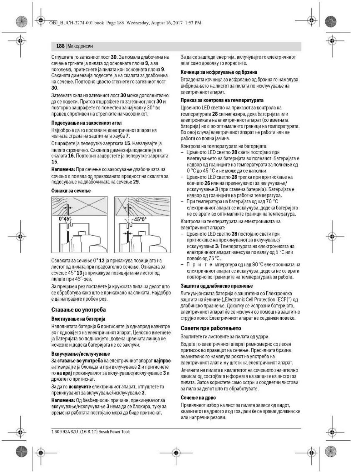
OBI_BUCH-3274-001.book Page 189 Wednesday, August 16, 2017 1:53 PM
MaKeJIOHcKN189
PnDOnJXHckNpe3OBHnCAmpekn,HactanyBaatdonnn,CnpaHnCTpyrotHH.
Pnabta 110 Hacnhya npn o6pbaTka n da b 6yka e ocbo h 8e Tna no npdajeto, 3atoa paobotete co Bmkybay 3 npaa.
Ceuebe co npapanehenrpaHmHnK (BnHn cInkA D)
PAPANEHHOT TPAHNNHK 11 OO3MOXyBa Ppeu3HN peo8N IIOJINKHTA HnIeIoT IIO ceOp6aTyBa, KaHO hI pIMep CeeHe HnIeTH CO CTNH DmHnEi.
Ceuebe co nomouen rpaHnHK (BnHnCnHaE)
3aOpbOtKaHa rolemnnapuHbA Hn 3a cceHe Ha npabn paobOn,Ha denot tio ce opbObya MoKe da 3aBepCTHe eHa DaCKA Hn JAcna KAKo NOMOwen TpaHHNHNK Hda ja BOHKe KpyKHATA Hn CO OCHOBATA NIOVA NOJONIKHATA NoMOOHNOrTpaHHNHK.
KyKHa3aKaayBaBe(BnDnCnkaF)
Co KkyKte 3a 3akaayBaBe 1 MoKe Da Ro 3akKaHnTe enEeKpyHHNtAnapat Ha np. Ha cKnA. OToBopEt HkyKte 3a 3akaayBaBe 1 Bo KaCnA noHauiJa
Pn3aKaayBaBeToHa eNeKTPNCHOTypeBHHMabajTe NcTOT 3aNNATAe aZaHTHEn OOBHHMaTeHNO DonnHpHe. TocToOn anachOg NOBpEDA.
IIOBTOPOCKNONETRKYKNT3a3akayyBahe1,KORAKe cakate da pa6oTnre co eNktpnHnOtnanpat.
HanomeHHaONTHMaHNOKOpHeBaHa6atePMHTe
3aunntete ja 6atepujata od Bnara h Boda.
CnApaJape ja batepma JBO rpaHnHnHa TEmpepaTpyo 0D-20°Cdo50℃.He jaocTabaje batepma HAp.Bo aTbOMBONOTNETHO BPEM
IIOBpEMHO YHCTETHE OTBOPHTE3a npOBETpyBaHe HbATEPHJATA CO MEKA, YHCTA H CYBA YETKA.
CkpateHOTOpBpeMeHaPabotaNoonnHeToNOKaKyBa,deKa 6abeepjatae noptpoeha H Mopda Ce 3ameHH.
BHHMabajte Ha Hanomehnte 3a otctpaHyaBahe.
OdpKxBaBe H cepBnC
OdpxByBaHe HnHCTeHe
Pepd6NnKaKaHHTpeBnJaHa eNeKTHNHO
anapat (Ha np. OpKByBa, 3neHa HAnatMTH.) Kaco
H pner Heron TpaCnOpT KcnAmpHe, 3naTeJa
6atejHpaJg o hero.Ppn HebHMataHNO paKyBaBo Co
PekkyBaHOT 3a BknyBuBaHc/HckyBuBaHe IOCTOn
ONACOHT O NobpeDn.
Ondpybaite ja hNCTOTATA ha nEeKTPHNNOT anapat H otBOPHTA 3a noMoKe do6pno H 6be36bdo da paoBtne.
3aHTHATAxay6coNobpateMexAH3mMopcKc0raJda ceDBMN CNObDOH Ja ce 3ATBOPa.IpeDenot OKNY 3aHTHATAxay6coNobpateMecAH3mCekorawTpe6a DaIbnE qHCT.OTCPaHBeJaPnBaTHcPTyrotNHHe Co HdyByBaHe co KOMnpcepcpaH Bo3dyHXnCetKa.
He6noxHnTe HCTOBn 3a Hnna MoKc Da c3aunTat OKoP03JHa CTOHOK CIOH BA E63KcEHHCKO MACNO. IpeD CEeHbETO,OTCTpaHETe Ro MacNTo,3a Ha He OCTABn DAKKnHa DpBOto.
OctatoyurOd cMOnA h nenak HnHCTOT 3a HnNATA ro HanyuBaAT KaBnHTerot Ha ceHeTeo.3aToa,CHCTeTn HnTOBtBEHaNnataNoynptbEta
CepBncha cnyK6a H COBETH npn KOpNCTeHe
CepBnchata cny6aKe OroBOpn Ha BauHte npaaHa BO
BpCaKo CNIOpaKaTHa N OPOkYBaHeto HA BauHOT IpnO3BOD
Kako H peSEpBHInTe DeNoBn. EKCTNOsIBHeI Uptekn
HHopOpMaun 3a peSEpBN DeNoBn Ke HajTe He
www.bosch-pt.com
TMMOT3aCOBETyBaHe npH KOPICTHeHa BOSCH KE BN NOMOHE DOKONKY HMAte PpAuaHa 3a HAuHTe PPOH3BODN H OPENMA.
3a Cnre npaaHn HapauHn HpaeepBn HneoBn,Be monHe habeTe ro 10-ndppeHHbOpoj cnueKuKaHOnata nouoka H npnoBBODT.
MaKeDoHnja
Д.Д.Енковский
Caba KoBaueBnK 47Hb,6poj3
1000 Ckonje
E-nowta: dimce.dimcev@servis-bosch.mk
HHTepHer: www.servis-bosch.mk
Ten./φακc: 02/2467610
Mob.:070595888
TpaHcnpot
THYMJ-OJHCKHTe BatePNN NOJIeKaT ha bapaHata Ha 3aKOHOT 3a OIaHc HATEpNJHn. BatePHTe MOKeJa cTe TPAHCNOPTHa cMoO dCTPna HA KOPCNCHKOT,6E3 Notpe6a od DononHteneHH KBaHnHkauHn.
IpynepnoHC hNCTe OCTraHbA TETPHNIIa (Ha np. B03JyDHNTPA HTHCNPTH NINHUNIJIa) HeONIOHO e da ce BHMMHA hCneJIHNNITE HANOMEN HA aMBAANAKATA H OAHAKITE. BO TAKOB CNYaj, npn noTobROKATA h NpTaKATA MOPa da c neBnKA ECKNEpr 3a onAHN CYNTAHs.
TpaHcnpnHpajte rnBatepHnTe camaDokonky KkyHwTeToe e HeoHeTeHo.3aeneneTH OTbOpEnHe T KOHTAKn Hn CnakyBaJte ja batepnjata Ha ToJ NaHn HtO HeMa Da Ce DnBKn BO aMgAnakkata.
Be MonHime BIIHMAbaJte HA eBENTaJIHNTe NOIONIHENTENHH HAIHOHANPHIOHN
OcTpaHyBaBe

EnKHTPHNTHe anapath, 6atePHNthe, onpemata H ambaJAKNTpe6a da ce oTcpaHat ha ekonooikn npdFATINB HauHH.

Hn fnojajre enekrpuhne anaparntu bateprrne BO domaunha Kana ta 3y6pe?


OBI_BUCH-3274-001.book Page 190 Wednesday, August 16, 2017 1:53 PM
190 | Srpski
Cama 3a 3emjn Bo paMKHa EY

Cnped ebpontkata perynatiba 2012/19/EU enekipnHne anapatni tto ce BOn yonptba n depeKTHnte nn HcokphtenHe 6aTeepn Cnped perynatbata 2006/66/EC Mopa oJdennHO da ce cobepa n da ce peuknmpaat3a nobotpa onyntpe6a.
Батугн:
JIHTHym-JOHCKH:
Be monnme BHHMaBajte Ha HanomeHHTe BO den , ctpaHa.
Ce 3aDpxyBa npabToHa npomeha.
Srpski
Uputstva o sigurnosti
Opsta upozorenja za elektricne alate

UPOZORENJE Citajte svu upozorenja i uputstva.
Propustikod pridrzavanja upozo
OBI_BUCH-3274-001.book Page 193 Wednesday, August 16, 2017 1:53 PM
Srpski|193
OBI_BUCH-3274-001.book Page 195 Wednesday, August 16, 2017 1:53 PM
Srpski|195
posedno u vezi sa dodatnim materijama za obradu dvrte (hromati, zahtina sredstva za drvo). Materijal koji sadrjiz abzebst smeju raditi sono smo strucnajci.
Da bi postigi visok stepen usisavanja prasine, upotreblajte usiisvac GAS 25/GAS 50/GAS 50 m za drvo ili GAS 50 MS za drvo ili mineralnu prasinu zajevoda so ovim elektrikhim alatom.
Pobrinite se za dobro provetravanje radnog mesta.
- Preporucjce se, da se nosi zašitna maska za disanje sa klasom filtera P2.
Obratite paznju na propise za materijale koje treba obradjivati u Vasoj zemlj.
OBI_BUCH-3274-001.book Page 200 Wednesday, August 16, 2017 1:53 PM
200 | Slovensko
Akumulatorske baterije ne odpiraje. Nevarmost kratke ga stika!

OBI_BUCH-3274-001.book Page 203 Wednesday, August 16, 2017 1:53 PM
Slovensko|203
Oznake rezov
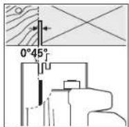

Oznaka reza 0^12 kaze polozaj zaginega lista pri pravokotem rezu. Oznaka reza 45^13 kaze polozaj zaginega lista pri rezu pod kotom 45^
OBI_BUCH-3274-001.book Page 208 Wednesday, August 16, 2017 1:53 PM
208 | Hrvatski
| Rüčna kružna pila GKS 36 V-LI | ||
| Max. dubina rezanja | ||
| - kod kuta kosog rezanja 0° | mm | 54 |
| - kod kuta kosog rezanja 45° | mm | 38 |
| Uglavlijanje vretena ● | ||
| Dimenzije temeljne ploce | mm 146 x 290 | |
| Max. promjer lista pile | mm 165 | |
| Min. promjer lista pile | mm 160 | |
| Max. debljina lista pile | mm 1,7 | |
| Min. debljina lista pile | mm 1,0 | |
| Max. otklon zubaca pile | mm 2,6 | |
| Stezni provrt | mm 20 | |
| Težina odgovara EPTA-Procedure 01:2014 | kg 4,3 - 5,0° | |
| Dopuštena okolna temperatura | ||
| - k od pūjena | °C | 0...+45 |
| - priräj kbd skladisteniya | °C | -20...+50 |
| Preporučene aku-baterije | GBA 36V | |
| Preporučeni punjači | AL 36.. | |
| GAL 36.. | ||
*ovisno od koristene aku-baterije
ogranicienuinak kod temperatura < 0^
Informacije o bucici vibracijama
Emisjske vrijednosti buke utvrdene sukladno EN 60745-2-5. Prag buke urerdaja vrednovan s A iznosi obicno: prag zvuñog tlaka 98 dB(A); prag učinka buke 109 dB(A). Nesigurnost K = 1,5dB.
Nosite stitnike za sluh!
OBI_BUCH-3274-001.book Page 217 Wednesday, August 16, 2017 1:53 PM
Eesti 217
Löikesugavuse regulerimine (vt jounist C)
OBI_BUCH-3274-001.book Page 222 Wednesday, August 16, 2017 1:53 PM
222 | Latviešu
4 Rokturis (ar izoletu notuvirsum)
5 Akumulatora fiksatora taustin
6 Akumulators
7 Aizsargparsing
8 Kustiga asmens aizsarga regulejosa svira
9 Pamatne
10 Kustigais aizsargparsegs
11 Paralela vadotne
12 Trases markejums zagesanas lenkim 0^
13 Trases markejums zagesanas lenkim 45^
14 Sparnskruve paralelas vadotnes fikseSanai
15 Sparnskruve zagesanas lenka fikseisanai
16 Zagesanas lenka skala
17 Taustins darbvarpstas fiksenaian
18 Papildrokturis (ar izolétu noturvismu)
19 Seestura stienatslega
20 Darbvarpsta
21 Balstapplaksne
22 Ripzaga asmens
23 Piespiedejpaplaksne
24 Stiprinoša skruve ar paplaksni
25 Markejumi uz aizsarga
26 Taustins uzlades pakapes nolasanai
27 Akumulatora uzlades pakapes indicators
28 Temperaturas kontroles indicatoris
29 Griesanas dzijuma skala
30 Svira zagesanas dziluma fikseshana
31 Skruvspiles (paris)
32 Uzuksanas adaptera stiprinajuma skruve
33 Uzuksanas adapters
34 Uszuksanas slutene
*Seit attelotie vai prakssttie piederumi neietilpst standpaigä des komplekta. PilsPARsparts par izstradajuma piederumiem ir sniegtys mùsu piederumu katalogä.
Tehniskie parametri
| Rokas ripzägis | GKS 36 V-LI | |
| Izsträdajuma numurs | 3601 F73 ... | |
| Nominalais spriegums | V = 36 | |
| Griësänās attrums brivgaita | min.1 | 4000 |
| Maks. zägësanas dzilums | ||
| - pie zägësanas lenka 0° | mm | 54 |
| - pie zägësanas lenka 45° | mm | 38 |
| Darbvarpastes fikseësana | ||
| Pamatnes izmeri | mm 146 x 290 | |
| Maks. zägå asmens diametrs | mm 165 | |
| Min. zägå asmens diametrs | mm 160 | |
| Maks. asmens centralä das jalas biezums mm 1,7 | ||
| *Atkaribba no Izmantojam akumulatora | ||
| **Samazinata jauda pie temperaturis <0 °C | ||
| Rokas ripzägis | GKS 36 V-LI |
| Min. zäga asmens pamatnes bie-zums | mm 1,0 |
| Maks. asmens zobu biezums/izliece | mm 2,6 |
| Stiprinajuma alveres diameters | mm 20 |
| Svars atbilstosi EPTA-Procedure01:2014 | kg 4,3 - 5,0* |
| Pielaujama akpärtejgaaisa temperature | |
| - uzladeslaikä | °C 0...+45 |
| -darbibas laika uglabāsanas laikä | °C -20...+50 |
| leteicamie akumulatori | GBA 36V |
| leteicamä uzlades ierice | AL 36.. |
| GAL 36.. | |
| *aktarban nozmantojama akumulatora | |
| "Samazinala jauda piemeteratures <0 °C |
OBI_BUCH-3274-001.book Page 226 Wednesday, August 16, 2017 1:53 PM
226|Lietuviskai
nemiet no ta akumulatoru. Nejaua siesledzeja nospiea na var izraisit savainojumu.
Lai nadrosinatu ilgstou un neavoinamu elektroninstrumenta daribubu, uzturiet tiru t korpusu un ventilacijas averes.
Instrumenta kustigajam aizsargam brvi japarviietojas un patstavigi jaizvertas. Tapezturijt iru aizsargu un virmas tatauvuma. Uzkrajotiesputekjemun skaidam, izpuiti ts no azzarga sara arsapiesta gaisa struklu viz itrij et aro.
Uzglabjot zaga asmenus beaz aizsargparklajuma, tie japarklaj ar planu karitju skabi nesaturosas ellas. Pirms lietosanas asmeni rupigi janotira, lauz zagejuma virsmas nepalktu ellasPEDAS.
Zaga asmenim pielipusas limes vai sveku paliekas nelabveligi etiekme zagejuma virmskas valitati. Tape notiri taget aasma ntilut peltac li tetloanasan.
OBI_BUCH-3274-001.book Page 236 Wednesday, August 16, 2017 1:53 PM
236|
OBI_BUCH-3274-001.book Page 238 Wednesday, August 16, 2017 1:53 PM
238|
中,
丕
串TRI 馮
图期则默国已用之在者期则用,求有
:BteT1是日月,中自。,
OBI_BUCH-3274-001.book Page 239 Wednesday, August 16, 2017 1:53 PM
中国文|239
OBI_BUCH-3274-001.book Page 240 Wednesday, August 16, 2017 1:53 PM
240|
新国
International Construction Solutions W L L
agJ:51JUJ
j
:97440065458+
:974 4453 8585 +UuSLe
:csd@icsdoha.comjgjjSxJy
aJgswll aJall aLooJI
aaii1saoaiaggJlaIy
1g
14 glS.oggioll auol gJluw
aJgswll aJyJl aSLoJI,21431 o
:9662667222+
:96626676308+u≤
:roland@eajb.com.sa gjgjS
UgW
aiaJUgJUJAA
:1030JUJI
:963212116083+
: rita.dallal@ hotmail.comjgjzJxI Jy
uigj
jgdd
UgJUw.5JabgbjUJ LJW7
juljun
wgc 2014
:21671427496/879+LJL
:21671428621+uS
:sav.outillage@tn.bosch.comgjgjSJI
aaiJduiJI Jlo
Central Motors & Equipment LLC
:1984J
iuluio-ooagglglo
a9JwI
:97165932777+
:97165332269+u≤l#
:powertools@centralmotors.aeJgjiSjI 一 _ 一
aJlUJLgAe
JdJlJolJllpoIyjI1Lw
:9671202010+
:9671279029+uS
:tech-tools@abualrejal.comgjSJyIJJ
Jai
gaggl gigolg aJgall gogil Uggl g
Lc pJol Jai gao j dssaua aaa.
aIbgsuuauiuguljll
:adelzaki@unimaregypt.comjgjSJ|JU
gJgiSill gaiI Lgao
Jiaol Jbo gJlu
152
:9647901906953+uJL
:97143973851+()ωj
: bosch@sahbatechnology.com, gjzSJU
J
Roots Arabia - Jordan
山
aJU37 aJ u
Jlac 11194
:96265545778+LJ
: bosch@rootsjordan.com, gJ S J d
UgSJI
Jn Jn
gaw auiial aabioi
13002 : 164
:96624810844+
:96624810879+UuS
:Josephkr@aaalmutawa.comgjSJ|
U
.Tehini Hana & Co. S.A.R.L
499-90:
gjU jgJ
:9611255211+
: service-pt@tehini-hana.comjgjsJx
U
yjzally osgdallg g jg a
Malatan Trading & Contracting LLC
:131JUJI
jIac aibluw
:968 99886794+ωjLm
: malatanpowertools@malatan.netgjzJxI J
jbo
jssuuiu. gaaaiI jue uaiI sduiai
.
aLio aJIOAC JALI 1 glll 1
aJyJoo
J. J. J. J. J. J. J. J. J. J. J. J. J. J. J. J. J. J. J. J. J. J. J. J. J. J. J. J. J. J. J. J. J. J. J. J. J. J. J. J. J. J. J. J. J. J. J. J. J. J. J.
.1JUWU UgUdUgUdUgUdUgUdUgUdUg
. Jdall jooalll sssu oolall gclj
ddJg dJIJI
cIbllg aJUJI
JdswlaLj:10) auiqSsJ 1 Jd jkuu. qia g lai si Lg (..g sall
labg Juaaui aiao lc baiu ic gay aylo
Jgaoo uJsw
Jg Jsuu a gull
aalaaalag aaijll alglln g k n u aal
aJzJIyLgIuZcUgLoUa aUbju
gIbgeaJIgJU gaiJI Ula Joo JuiuII JuaJI UjI .oJdabwlg
g26jjI Ic bdoJI Sic 28 JJLED aJLOaogj
:(uJpaJall lai)3L/1jfoil 1
.1j0i 0jA aJ d gawalgul jla sJl
aJlJI aJd JI pSJIJI gJU 70°C u
.
:ajjJ0jollgjjSjIolbllojlaa jda
gao 1c bai jie 28 0a 1jia jia jia jia
jda jgj:Jauu uKu 3LbIg Juaill
g15°C joljaiyJl oJy aigjLJI jq
1.75°C 100 jisi
pull 90°C jc ojdl a d sui loic
J 1
aagawalulwlljda
gjai jai jgi
glll l o glll Ulg! aLg qd
151JUeEerTngHcHueHgipjIJIeHuogabWg
aawlgy auyuJySJJ oSJJ -Lb! .“(Protection (ECP
Joo oxc uj j:osjol lo sic aLg ajl
.
<ggawg ayjySJI 8sJI aJbJ Jc JdJ Ldo
.1gJbIg CLoaJI Joo JuaJI Juaai aLag
J 1
oo joo oolgJ gJbJ .
aJgSJJ 000 Jg jis (jwI oac aal
Jswg aIyS Jswg bai oog mll jd g
.1g qilq 0 gjol 0 slal aai jllg
wJ
g ggaggaggggaggaggaggaggaggaggaggaggaggaggaggaggaggaggaggaggaggaggaggaggaggaggaggaggaggaggaggaggaggag
gI gblgblgblgblgblg
.
jlll jyll l aagbll ggbll n
JUJUJJgjLJI
.0uabolgoJooJIbaoJooJI
(Dgajglj)glguloo
JUa 11 jil
a glwaiI bgbjI gbiJswi dabg aia
(Egglj) sLo gull
gJgJgJgJgJgJgJgJgJgJgJg
aaS aojlc g1 g2 gj cuiS aaiwJl
abawlgj jll jiaai dagil jwlae bglc swo
.5uJJJ Jua Lc e xlaia
(Fgjglj)
1 000000000000000000000000000000000000000000000000000000
gjolgl 1 glll
.
-psjoljda
aIJI bJUgj
7 aIglll 12c ags lc wyljSll oJSS J
.
jaiJI. jilU JiaIJI 15 jaiJI jgUJ
15 gaiJUgUJ WpA.16 wuOJI Uc Ugjol
.
gocgSulilIuluill ggbjol sic:abdo
gac wlaao Lc qll jwoll aai ljo jao glaill
.29
gblaoai pui
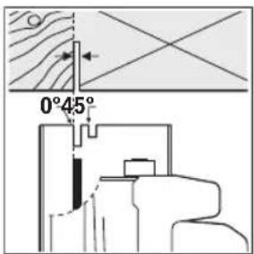
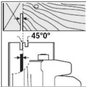
1sic jwioioll 10j sjo 120gbai aolc m w jso 1345gbai aoL c .aggl aalg gboa 45o Ld aggl eggbai
g 13 jasasabla slll juaill j s
山
a5jollu5
6sJg 6sJg
6sJg 6sJg
6sJg 6sJg
6sJg 6sJg
6sJg 6sJg
abg
3.1g 2
3labg jllaloojayaiyla 10aI labx 3labg lalao y aol o
Jolno lqosaiu loic bag auljgSll o211 Jw
JgJI:laJlLso
gUJgUOaQySjA UJgUoI Jolqn 1
aJJI aJgJg
28 128 yjll jll jll jll jll jll jll jll jll jll jll jll jll jll jll jll jll jll jll jll jll jll jll jll jll jll jll jll jll jll jll jll jll jll jll jll jll jll jll jll jll jll jll jll jll jll jll jll jll jll jll
:JSLJI JJIaJdJIaJI
aJbUjIg bglal oicS aieoai oocai jn 100000000000000000000000000000000000000000000000000000000000000000000000000000
GAS25/GAS50/GAS50M aJgJI abgLIJI aJgJI UjJIgI gI/g GAS50MSgI
.0ddujglll 0dall 20
Jlaaiw 1ij.
.P2 wJall aai yaaill aLg g li jy aai - 1gall aywll pss l q Jauu IaI j
-,uU
Ji jg. Jl kai j 1j ci
(GgJgJ) aIgJI bawI aIog uSj
32 1gJ abwJg 33 aIqal bawll alog Cw J9 oclJI ayoLgl
baw pgbj 33 ayqal bawl aog yu jnsos .00 35 gbu
abwbu pui j aIgll bawll alog cJj g J. bawll oig sww sag 2g.
xg jg. qglb bai lgl yj g jy 10g jg 8 10aui pui
abio 33 aIgai bawl alog cbiy
Jl
(gglj)a1gla jucabglu 34 bawl ggbj buj l a1gla juc u2glu woglu joc lc jia .auiSIO aaiy aolio
osloo JlaoiW aIgai Jaua abaw aui j u
oJcBbW Si d aIa JgJc abaw PsaI IaI IyssI gI Ubbuauu uuuuI gAuluO
山
山wIg
4.aJy≤J0
(Cgjglj)gbll gacb
JUJI 1 JUJI
U
30 15
9 9
9 9
9 9
9 9
9 9
9 9
9 9
9 9
9 9
9 9
9 9
9 9
9 9
9 9
9 9
9 9
9 9
9 9
9 9
9 9
9 9
9 9
9 9
9 9
9 9
9 8
9 8
9 8
9 8
9 8
9 8
9 8
9 8
30 30
JJJ J1111111111/
JuiiJI Jai uui Siic aIg Ujlaa JJ 29JauuUaJbUaJUaJuaUaJUa
.0Jlaaiwai awljs 9jgsdJI
.
juiiJI jui
aIqiu IqIooiU giaoiJuaiou Ugdsaw .awlJSIO
(AaJgallj)JiaIJI J
JLg JIagJI Ic aui jSIO sJ Ua oJ
. 111111111111111111111111111111111111111111111
17 1g jg jg S 1g gjg jg
19 1gJgJgJgJgJgJgJgJgJgJgJgJgJgJgJgJgJgJgJgJgJgJgJgJgJgJgJgJgJgJgJgJgJgJgJgJgJgJgJgJgJgJgJgJgJgJgJgJgJgJg
a 10 aagai gai Lg
jg22 jaiai1 jgi 23 aaw gji - .20 jwi
(A ojgai glj) juiiai iuiu 5
JUaJIagJI JcawjSIOJ 1Joo
glll 22 juii1 -
a 10 aaii aLgI Lbc aI .pS
12 22 jj -
jLc aJl) jLiJg iJg
aJLc JGJLc jJg JgW go (JiaiJ
.10
aai 24 uJg 23 aow g
dai 1c b9g 17 jggJj gao JJ uuS - .wgs
19 1234567890123456789012345678901234567890123456789012345678901234567890123456789012345678901234567890123456789
25 aJy bgs 1g jg 14 Lc 7 aygllbc
jull/JIJI b
1c ggiy jlll lglg 1j
1jlaag 1jlaag 1g 1g 1g 1g
1g iiai 1g aai 1. aai y oao 1g
1g /g aaww 0j 29 g j 1g
1g 1g paaaill 1s daaaai 1g 1g
. uall no aja 1c n y glalgl a
GgUgUgU UgUgUgU
- auiuieiuee eae
gaaal jaiolll oogaiu Ulgj aLg qai
Electronic Cell" aigj<151 lalag abwlg 4uulg gglglllglgglgglgglgglgglgglgglgglgglgglgglgglgglgglgglgglgglgglgglgglgglgglgglgglgglgglgglgglgglgglgglgglgglgglgglgglgglgglgglgglgglgglgglgglgglgglgglgglgglggl
4 Jss ssc u c lge gulgul pssu w
labil sbablg luiu c baiy 1
. palsl cali . jksw ayj kll
. sall no yalill say cbalal
aJaiEji
giai jI gllg jnnl lalj 6 pssjll jaoa
pssjll lalq i jjjusu 9 aJLL pssjll bgaow
abwlg pssjll jLsji Ic laq y .gaaoo u c Jsw 5
.ajyssjll oessi jSro slo
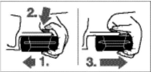
:6o5j11gjjj
uai g(1.) aui jgSJI oJJI oJcI gJ pSJIJI bau - .2.5 Jia jj lc qgl
-1b2()
.(3.) _a^b u dt
J5J 5JjJJ
(Bgajglj)psjllnawu
Jw ala wog aIil Iyall aIyall ayolal yaw 1u 6 pss Jw ala 27 pss Jabo auuul ooll uq lo sic bq pss Jw
UoJb aaleio uu
ejj 9 jn jn jn jn jn 26 jll wsl 5 aai j slj no n nnw lla w go Iabj .pall
gao jao
jai3x jaiuio-g≥2/3
2xjaiuio g≥1/3
jai1x jaiuo-g<1/3
1xglao-go bla
jll bcdoal ssu yoo go s ool p xu Ula 9 4. aui jessoai jssi
aii iiaai aiaai aiw gall .n nnai alac lii
aai jni ngi ngg. alwg .abii p qas gl
aii iiaai aiaai aiw gall .lo sic Jols Usw
aii aiaai aiw gall .abig ggoj Jaunu ulsw
5 0 s Jol Ls jssj jw d.
| EPTA-Procedure w jgll 4,3-500:2014 | |
| 0...+45 °C | d j Lg |
| -20...+50 °C | sic sic - |
| lga lga lga lga lga lga lga lga lga lga lga lga lga lga lga lga lga lga lga lga lga lga lga lga lga lga lga lga lga lga lga lga lga lga lga lga lga lga lga lga lga lga lga lga lga lga lga lga lga lga lga | |
| AL 36.. | jg |
| GAL 36.. | jg |
| * <0°C w * | |
Uljjg uall jc Ulog
EN60745-2-5JUaU LaaaL aagau
sgiu:5Jc(Aeji)jLJIa# sgiuao
Ssui jjimll yoeil lai oLs
jgl jgljgljabbyjllgololj
J 100
Jos Joo Jolc jog Ujuiu
Laaa aagj jiai g1 15
aJU U bU Jg j uoo 16
jIgJJIgoo Cuijj 17
(ugjso yaiJI abw) gol! jao 18
19
juii jIg Jg 20
Jog aai 21
*gJJJ JuiJU 22
aaw 23
aLggo wUgl 24
aLgJI.1bcJcdoJc 25
jwll aJLJ wg jj 26
pJJI Jw dJLa wgo 27
oJlJl aJz Jg o Jg 28
gabll gac wluao 29
Laaa gbaai aoc baiw 30
*oj10gj31
aIgJI bawJI alog CJ 32
aIgJIbawJI aIg 33
*bawul pgbj 34
gjgaaalglgllslaicuuljngjjl jnaa
gll liolj y daiSglgll gll j
aaiiui
5j1s 59
aiJ3601F73...
wJ1 JgJ1= 1jg936
14000
JUJJgJJJ
GgB
54 00
-0°cbuδaagj
38 0
-45°u,bwagglj.
jIgJgoo
aclal aauw uwlao146x290
gJluiuJUj165
jdsJlJwaiJI Jai jbaa160
oo1,7
J 1
oo1,0
jgai jaii elaw jsi
gaiuaiia/uaa2,6
paaialpajll
aJgJnJnJnJnJnJnJnJnJnJnJnJnJnJnJnJnJnJnJnJnJnJnJnJnJnJnJnJnJnJnJnJnJnJnJnJnJnJnJnJnJnJnJnJnJnJnJnJnJnJnJ

Jusss
aagjgglgglgglgglgglgglgglgglgglgglgglgglgglgglgglgglgglgglgglgglgglgglgglgglgglgglgglgglgglgglgglgglgglgglgglgglgglgglgglgglgglgglgglgglgglgglgglgglgglgglg
.
J 1 J 1 J 1 J 1 J 1 J 1 J 1 J 1 J 1 J 1 J 1 J 1 J 1 J 1 J 1 J 1 J 1 J 1 J 1 J 1 J 1 J 1 J 1 J 1 J 1 J 1 J 1 J 1 J 1 J 1 J 1 J 1 J 1 J 1 J
JloB1 UabLg LqIywi - aSISjRl ao saH
JJIJIJIJIJIJIJIJIJIJIJIJIJIJIJIJIJIJIJIJIJIJIJIJIJIJIJIJIJIJIJIJIJIJIJIJIJIJIJIJIJIJIJIJIJIJIJIJIJIJIJIJIJIJIJIJIJIJIJIJIJIJIJIJIJIJIJIJIJIJIJIJIJIJIJIJIJIJIJIJIJIJIJIJIJIJIJIJIJIJIJIJIJIJIJIJIJIJIJIJIJ
juii juiiai jai iuiu g baii j - gai juiiai juyg aJl Jc u yueu uao ,glaiol
g j gjll g w jwlll jai jn! - jiuill jai aiaa iuiu u kuiu uua uuiu uuiu uuiu uuiu uuiu uuiu uuiu uuiu uuiu uuiu uuiu uuiu uuiu uuiu uuiu uuiu uuiu uuiu uuiu uuiu uuiu uuiu uuiu uuiu uuiu uuiu uuiu uuiu uuiu uuiu uuiu uuiu uuiu uuiu
JluuI psswAaW ydsjSlaaal n! Jua o qui jSag. aue gglbLa Ssw .JdAaUaai IaiaI
pokn jydyabawg yjg jg j g j g j g j g j g j g j g j g j g j g j g j g j g j g j g j g j g j g j g j g j g j g j g j g j g j g j g j g j g j g j g j g j g j g j g j g j g j g j g j g j g j g j g j g
aagg gdsuolg jlll 2. aJall nJuiial lai f qg yI J I Jn Jn Jn Jn Jn Jn Jn Jn Jn Jn Jn Jn Jn Jn Jn Jn Jn Jn Jn Jn Jn Jn Jn Jn Jn Jn Jn Jn Jn Jn Jn Jn Jn Jn Jn Jn Jn Jn Jn Jn Jn Jn Jn Jn Jn Jn Jn Jn Jn Jn Jnn Jnn
sIg bll 1JUaill Jn jSjFJUaill Juaill aab g uill liw uLsi pse no a2b9 jla uJyDgJuiaill Jau Jl Jus W ole sic aysl wJ do so yg Juaill
Ld j 1s i s i 1i 1i 1i 1i 1i 1i 1i 1i 1i 1i 1i 1i 1i 1i 1i 1i 1i 1i 1i 1i 1i 1i 1i 1i 1i 1i 1i 1i 1i 1i 1i 1i 1i 1i
suc 1.0sag aabj gbbll ssc la jle bla a liy qulp aill oalgball gglgbl
sic piaiwo hui bgsaia 19 aaiu uui logw ci lglj calsll qua .g
aill lalalnglaiu jiai jaijai jai jai jai jai jai jai jai jai jai jai jai jai jai jai jai jai jai jai jai jai jai jai jai jai jai jai jai jai jai jai jai jai jai jai jai jai jai jai jai jai jai jai jai jai jai jai jai jai jai jai
p5joo gajll aaiwgl aloju
jllnssl o jg bao pslalnns lglal y gwi jpa aaii jp no qol sswy pnlqal no nnoe gil aasall nwl o jg .palsl no jEgi 0qol s
U LgLgSjIgIgIgIgIgIgIgIg
aJyjglll 1sAaiw g aoln mnn
elawil pdoaiwl.jqlll bpoj k
Ukuiuuii. uuiuuiuuiuuiuuiuuiuuiuuiuuiuuiuuiuuiuuiuuiuuiuuiuuiuuiuuiuuiuuiuuiuuiuuiuuiuuiuuiuuiuuiuuiuuiuuiuuiuuiuuiuuiuuiuuiuuiuuiuuiuuiuuiuuiuuiuuiuuiuuiuuiuuiuui uiu uuuuuuuuuuuuuuuuuuuuuuuuuuuuuuuuuuuuuuuuuuuuuuuuuuuuuuuuuuuuuuuuuuuuuuuuuuuuuuuuuuuuuuuuuuuuuuuuuuuuuuuuuuuuuuuuuuuuuuuuuuuuuuuuuuuuuuuuuuuuuuuuuuuuuuuuuuuuuuuUUUUUUUUUUUUUUUUUUUUUUUUUUUUUUUUUUUUUUUUUUUUUUUUUUUUUUUUUUUUUUUUUUUUUUUUUUUUUUUUUUUUUUUUUUUUUUUUUUUUUUUUUUUUUUUUUUUUUUUUUUUUUUUUUUUUUUUUUUUUUUUUUUUUUUUUUUUUUUUUUUUUUUUUUUUUUUUUUUUUUUUUUUUUUUUUUUUUUUUU
aBulg y Jauy g aai I 11 duiIg h
Joo
aJgSJJ ssll aolc aJoo bdo
A 1
AaI aI aI aI aI aI aI aI aI aI aI aI aI aI aI aI aI aI aI aI aI aI aI aI aI aI aI aI aI aI aI aI aI aI aI aI aI aI aI aI aI aI aI aI aI aI aI aI aI aI aI
a
gI jIJI gI JIgWw qJg Wg Wg Wg Wg Wg Wg Wg Wg Wg Wg Wg Wg Wg Wg Wg Wg Wg Wg Wg Wg Wg Wg Wg Wg Wg Wg Wg Wg Wg Wg Wg Wg Wg Wg Wg Wg Wg Wg Wg Wg Wg Wg Wg Wg Wg Wg Wg Wg Wg Wg
aai 8 . aui jssll ssll Josu wloic s
yJyJU JU
:glj dolj gac 1sIgwsI Jb
SjSjOlaI Jg Cg gds Sgss 2012/19/ gJgJ JgJgWgGdol jI gU gJwJgWgJgUgEUGdJgU2006/66/ECLgJgJgJgU

.iggglg CwjjbLc wlii
:1
:Li-1)gjgjj
a256 a0o. “olBsw Joo" uoo oJoo dIab
.
.1bga 5muai digg(g)
aIgai jw mol yj d aS sis Cg S .JU gag calpa. Jao ng 11 11 11 11 11 11 11 11
LuljLd aagogai gJgJgG
Sla uJyBlyg jjUaB 1s g JyI yI gia SjL aai Sdyilo wSyjlalgoo aannu IjdsuiauuiuuiuuiuuiuuiuuiuuiuuiuuiuuiuuiuuiuuiuuiuuiuuiuuiuuiuuiuuiuuiuuiuuiuuiuuiuuiuuiuuiuuiuuiuuiuuiuuiuuiuuiuuiuuiuuiuuiuuiuuiuuiuuiuuiuuiuuiuuiuuiuuiuuiuuuuuuuuuuuuuuuuuuuuuuuuuuuuuuuuuuuuuuuuuuuuuuuuuuuuuuuuuuuuuuuuuuuuuuuuuuuuuuuuuuuuuuuuuuuuuuuuuuuuuuuuuuuuuuuuuuuuuuuuuuuuuuuuuuuuuuuuuuuuuuuuuuuuuuuuuuuuuuuuuuuuuuuuuuuuuuuuuuuuuuuuuuuUU
(Fgagadgoggegaj)ggl
1jg 1 jg 1j g 1j g 1j g 1j g 1j g 1j g 1j g 1j g 1j g 1j g
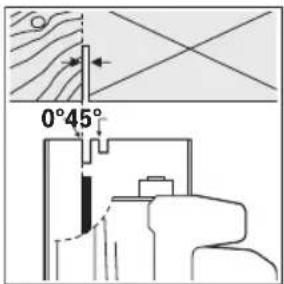
jy slg jc oai
jgo j2g 21 jjjjj jjclwos
dawl dwlslgj 23
gJwJolSus17jgogcuas
. 1
24 Jq 19 w 1Jd
(LED) jjw jw daw, (jjj
.iguogolagjuggJoo igS jUw
jwgj ggljgbj (LED) jjuw jj w dwwdjiu
.0wJjJwJolS jgbSjIyOgai! J,siIa
jIwJolS jgby 5i j1 j 5j u
gagogolla (LED) jjuu eJus
oJ da juyogj/5Jlssgai
<μU.μHJlj
.
4 laiwi
aJgSsJyWjbaOjdaJyJwlaJ.
.
4 Luaia dS.
山
sijoslui
aui
jI slqil jSslqiw jSl oJ dij Egljl Sjogai
wol ofoiaimjdjg
0jA (uJ5 oJlu) uJ5 Jgai
(Agawd gwEgj)
μ|gμj|cWl jq, taiao g |jbl aogai sl
.1Jggo di (Lla baw) jluw
gJuigjOgws17 jgaggdoS
. 1000
A
olss(caw)jgoo jolggi gio jg
jIjI jSsWJlKol JgaiI jS.
.
24 24 wg 19 wu w uJ uU dUw g
.1gjgljgljg jz
1jg uui juc aU 10 JsgsiaIblas
S_ OBC = 12 · CD · BC = 12 × CD × 5
20 oJ (caw) jgoo 12 20 oJ d2g 23 Jgo jjLg -
.
uai
HJ 0j
a j 1j0 gww
jul jJlwhgai
aJus aJslg as Jg jllj 1 gaw.du (olss suij u (59)
Sla 10i j 10la i 10s la i 9 10k 10j 10a 10s 10s 10j 10s 10j 10j 10g 10g 10g 10g 10g 10g
Jgolwdsjgl jI q. Siai Jy
Jg u g uuus ybl u Uauil qy jy
gola uuill jbl dks cds yuol
Lw ciSll okiu wos pOim dsu.
UuJg uolswgwhg gdo s 59
sUw yg ww wu nssu
s s g j 1 j 1 j 1 g o s i s aai j 1 j 1 o s i s s s s s s s s s s s s s s s s s s s s s s s s s s s s s s s s s s s s s
0s ylaui ggsy jiaobosg sgl slyu 1o oji jy d. ais bs agam J sga Jslg jj ojiia u c slc cng j l kji jil jilg .duw du jui
sLg sLwJnDswg jI. dWg y wu L g wU, Lgo. dS S JdGg Cuij Jao g oLsiu Jla JSLwBai j I J uSsiu ciu j g sily 590, sLg sLwJ. dJg S Jg Jua Jla JSLwCauu JcwJksoo O
g jg g s Js So JIw g dIg G Jg Jg 10i o iu u Jj IJg g Oii S g a dUug
G C wJd UJWg u dS g Wnabu y, Si
g Jg Js So JIw g J Olaaw , g W g Olaaw g
.6o o o JJc g Jy Jl Jlaw ng
1jI Cg jJl Jl 0slaWl
Sglgsolw SgJ slj JgJ
U L Wio kjjll JjI gJ .s
L Wio kjjll JjI nJgJ .s s laWl
U Jaab I g jg oLwS Ugi JI sJg uo
. sOlaWl Ju
jI gJlJI Jlog ggbS JSLJlI UgJ S
JglJdS JsJiSJI JJI. Jsi oiaW s
JooJy gOog SliJbS Js Jlog ggbJ Lqji
.igw
<1sloIg bao jjJljlLgjjg
w]
iJl
c] sI J I S J G a c J I S L J IaJ 1
I J Iaimg jIgws daom 4
JUcLp sC j UwU Laiu .ilgs
Gsiagw. gSjg CwU SsOg iay Irgws
.ogw dy w slj y
oJgao 111111111111111111111111111111111111111
4 dwlglu gblg jjI jI Jd sdu blo g o 100
clg jgi gjolbs
glo glo 15gag
aam 1
i 1 w s j i S a
SjS|
J 1s Jd aLwgs Jg jgi g SbU JIJI IJIL bJg dAol g Jg JIa dAol g Jg JIa dAol g Jg JIa dAol g Jg JIa dAol g Jg JIa dAol g Jg JIa dAol g Jg JIa dAol g Jg JIa dAol g Jg JIa dAol g Jg JIa dAol g Jg JIa dAol g Jg JIa
Jg g jgljg w aJ 10oJ 92gaw y Jy waiu uoo J .sS sJg
Llawwlauiuuaa g noj ay Jiai (J) Lab
.uy uuij f jf jy jb, uoj
gai jgi ggbjglj1j10kws jia|jjSjSjSjSjSjSjSjSjSjSjSjSjSjSjSjSjSjSjSjSjSjSjSjSjSjSjSjSjSjSjSjSjSjSjSjSjSj
aLgS gJgJgJgJgJgJgJgJgJgJgJgJgJgJgJgJgJgJgJgJgJgJgJgJgJgJgJgJgJgJgJgJgJgJgJgJgJgJgJgJgJgJgJgJgJgJgJgJgJgJgJ
jI bss sI aS ss oIaI IJI JI lii
bss sI y wLIO bJy IJ Ls .wU y wLIO jI
.iiS o p s l Jg i
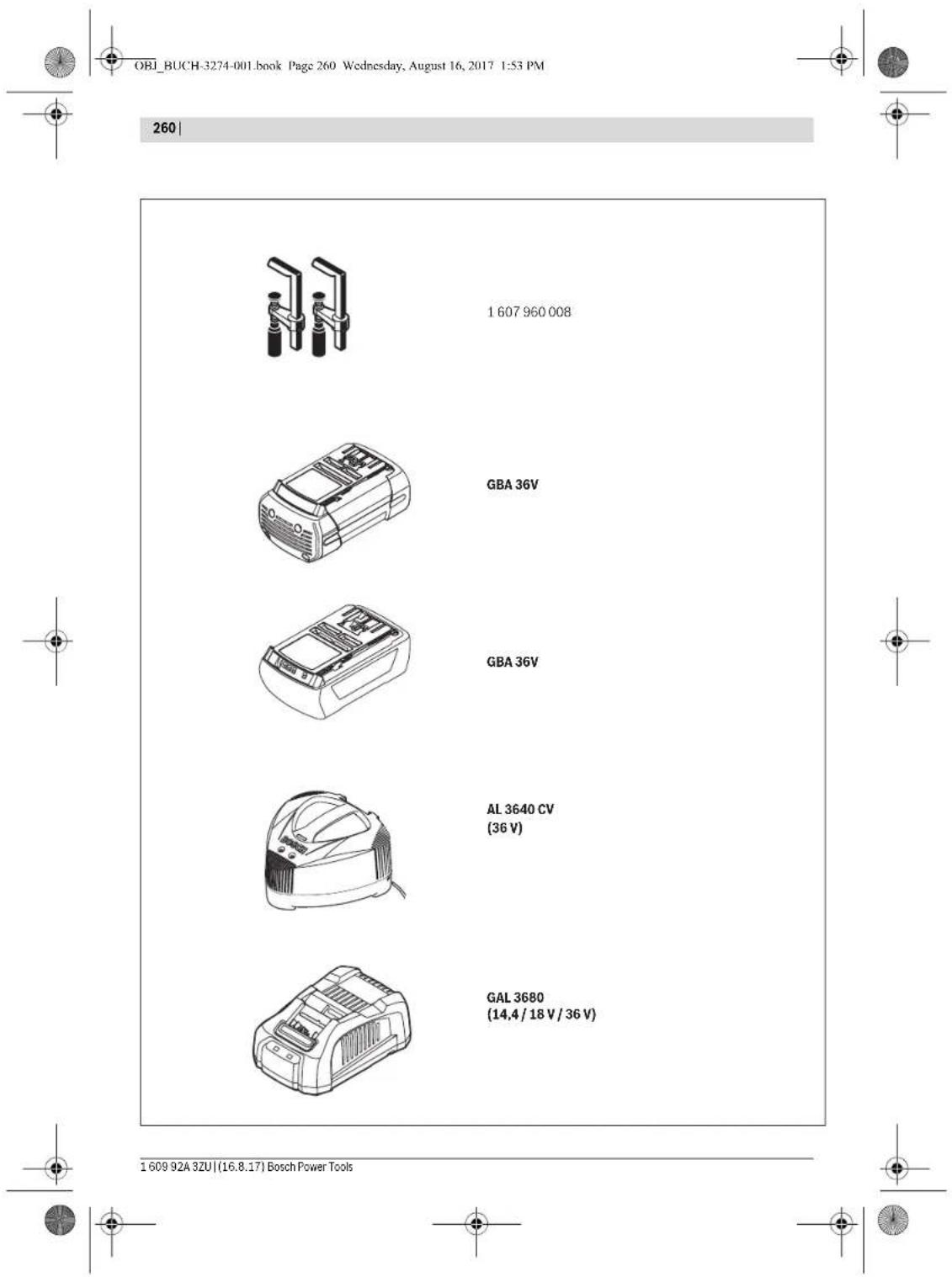
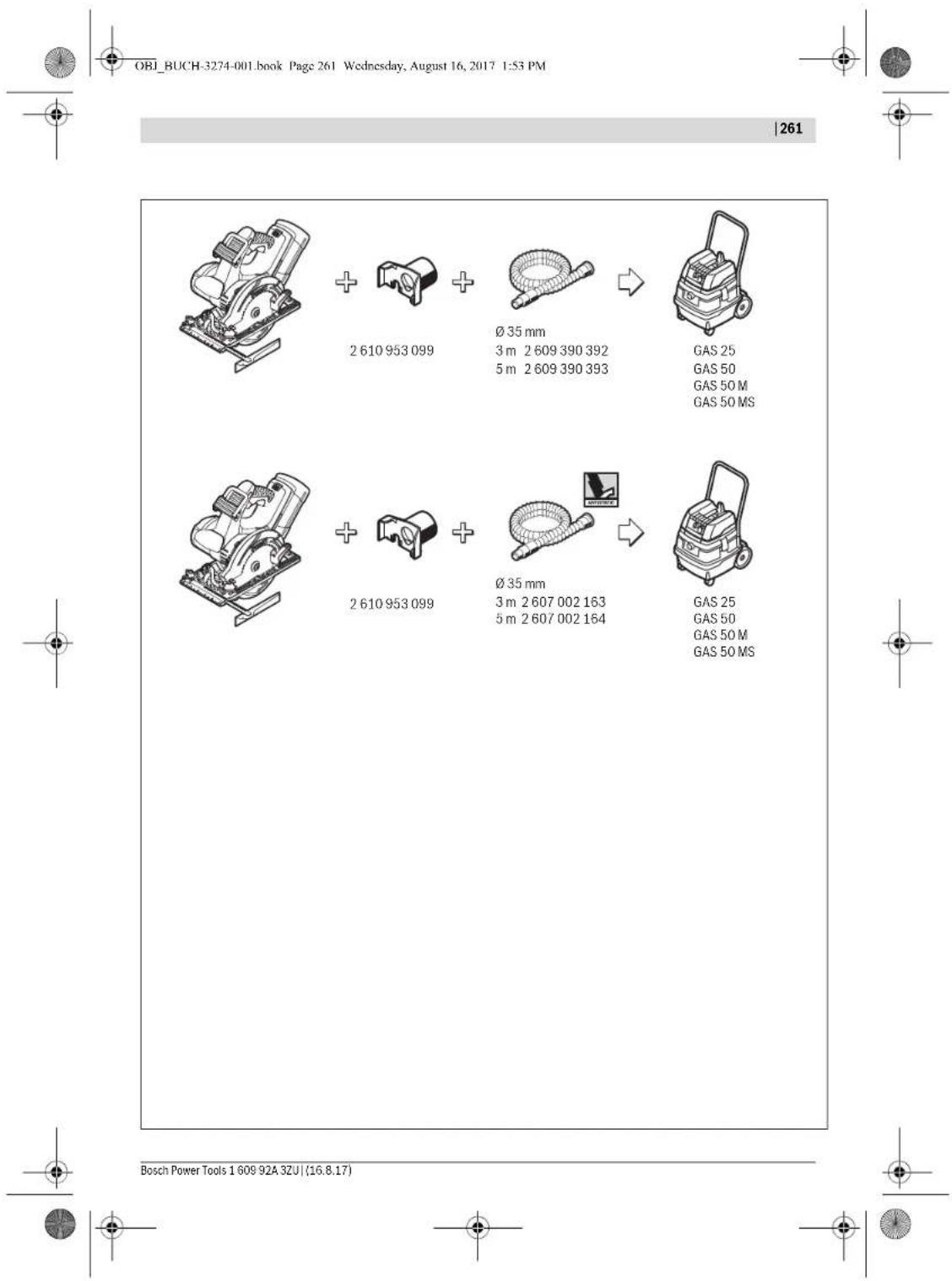
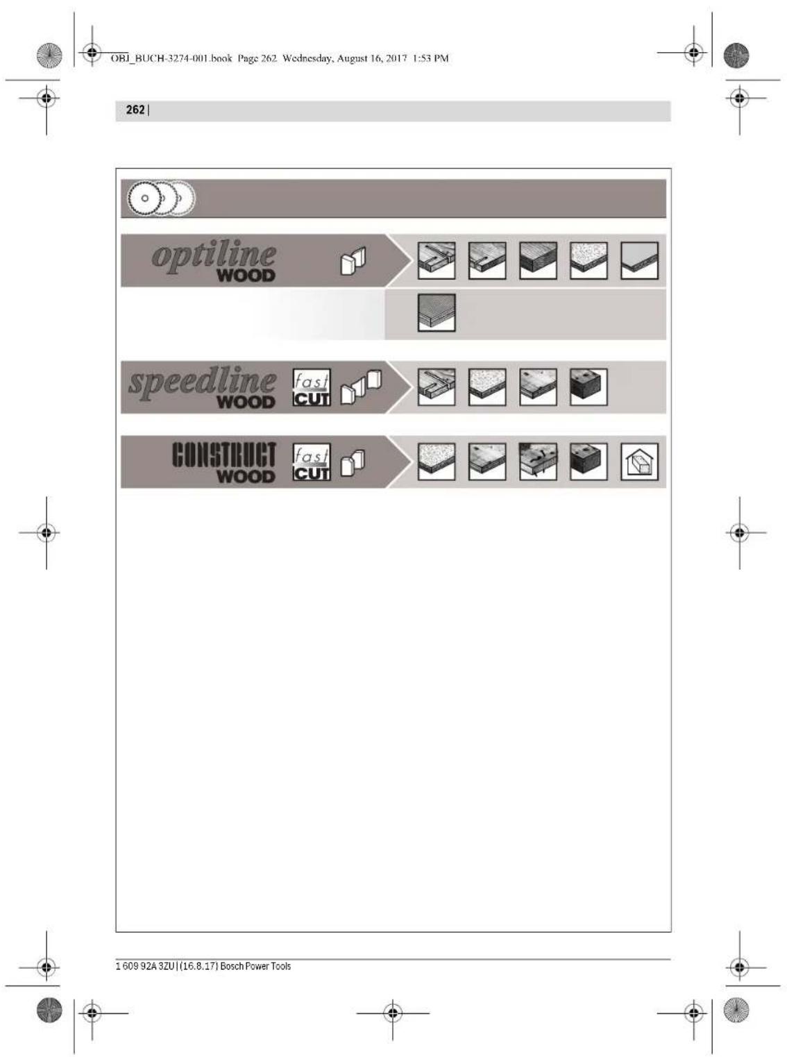
OBI_BUCH-3274-001.book Page 1 Wednesday, August 16, 2017 1:53 PM
| C€ | I | |
| de | EU-KonformitäserklarungHandkreissäge Sachnummer | Wir erklärern in alleiniger Verantwortung, dass die genannten Produkte allen einschlädigten Bestimmungen der nachfolgenden aufgeführten Richtlinien und Verordnungen entsprechen und mit folgenden Normen übereinstimmen.Technische Unterlagen bei: * |
| en | EU Declaration of ConformityCircular Saw Article number | We declare under our sole responsibility that the stated products comply with all applicable provisions of the directives and regulations listed below and are in conformity with the following standards.Technical file at: * |
| fr | Déclaration de conformité UEScie circulaire N° d'article | Nous déclarons sous notre propre responsabilité que les produits décrits sont en conformité avec les directives, règlements normatifs et normes énumérés ci dessous.Dossier technique auprès de: * |
| es | Déclaración de conformidad UESierra circular N° de articuloportátil | Declaramos bajo这是我们 exclusiva responsabilité, que los produits nombrados cumplan con todas las dispositions correspondientes de las Directivas y los Regimientos Mentionados a continuación y estar en conformidad con las siguentes normas.Documentos tíncios de: * |
| pt | Déclaração de Conformidade UE Serra circular N.° do produitsmanual | Declaramos sob{nossa exclusiva responsabilité que os produits Mentionados cumprem todas as dispositions e os regulamentos indicados e está em conformidade com as seguintes normas.Documentação técnica pertentente à: * |
| it | Dichiarazione di conformità UESega circolare Codice prodotto | Dichiariamo sulla nostra piena responsabilità che i prodotti indiciati sono conformi a tutte le disquisitioni pertinenti delle Direttive e dei Regolamenti elecanti di seguito, nonché alle seguniti Normative.Documentazione Tecnica presso: * |
| nl | EU-conformiteitsverklaringCirkelzaag Productnummer | Wij verklaren op eigenverantwoordelijkheid dat de genoemde producten voldoen aan alle desbetreffende bepalingen van de hierna genoemde richt-lijnen en overeendenmen met de volgende normen.Technisch dossier bij: * |
| da | EU-overensstemmelseserklæringsHandrundsvay Typenummer | Vi erkralar someneansvarlige, at det beskrevenue Produkt er i overensstommelse med alle gaelende bestemmelser i falgende direktiter og forordninger og opfylder falgende standardder.Tekniske bilag ved: * |
| sv | EU-konformitetsförklaringHandcirkelsäg Produktnummer | Vi förlkar ar under eget ansvar att de namnda produkterna uppfyller kraven i alla gällande bestämmler i de nedan angiva direktiven och fordringarnas och att de stammer överens med följande normer.Teknisdkodumentation: * |
| no | EU-samsvarserklaeringHandsirkelsag Produktnummer | Vi erkralar under eneansvar at de nevnte produitene i overensstemmelse med alle relevante bestemmelier direktivene og forondningene nedenfor og med falgende standardder.Teknisdkodumentason hom: * |
| fi | EU-vaatlmustemnukaisuusvakuutusKäslypörösaha Tuotenumero | Vakuiutamme tätten, etta mainit tuoteet l vastaavat kaikkia seuraavien direktivien ja asiankuuluvia vaatimuksaia ja ovat seuraavien standardien vaatimusten mukaisia.Teknisenet asiakirjet saatavanana: * |
| el | Δηλοση μετόπητε EEΦρητδιδίκomplovo Αριθμος ευμεπρού | Δηλονούμε με στασκίστιοική τος ευμύνη, ὄτι το αναφρούμενο προίουντανιστογούνινος Ελεός τος ευκτικό διατάξες, των πο κατωναφρούμενωνοδημηκ και κανονιαίνικων και taúntίονται το τα ακόλουθα προτήνι.Tεχύκε ἀνραφο στη. * |
| tr | AB Uygunlik byeaniDaire testere Ürūn kodu | Tek sorumlu olarak, tanımlanan ürūn污水处理ik ve direktifilerin geleçeri bilirün hülçümelerine ve asşigiaki standartlara uygün oludünguni banyenan ederiz.Teknik belgeliner bulundügu yer: * |
Bosch Power Tools 1609 92A 32U (16.8.17)


OBI_BUCH-3274-001.book Page II Wednesday, August 16, 2017 1:53 PM
| II | ||
| pl | Deklaracja zgodnosci UE | Oświadczamy z pełna odpowiedzialnoscia, ze nimiejsze produkty odpowiadaj wyszystkim wymaganiom poniżewy wyszczegońnych dyrekty w Rozporjadźne, oraz zę są zgodne z natestpućzymi normami. Dokumentacja technickza:* |
| Reczna pilarka tarczowa | Prohraśjemu na yvhadrni zodpovednost, zę uvdeny výrobek spluţuje vsechna príslusné ustanoveni niżv uvdenych směric a nařizeni je v souladu s nasludujcimi normami: Teknicke podklady u:* | |
| cs | EU prohlášeni o shodé | Vyhlasujemu na yvhadrni zodpovednost, zę uvdeny výrobek spluţa věsétky príslusné ustanoveni niżv uvdenych směric a nariadeni je v sūlade s n as l ud j učim i normami: Teknicke podklady m spolocnost:* |
| Rucnokotučovipla | Egyeduli feleş§gell kijelentjuk, hovy a megnevezet terméké megelelnek az alabbiakban felsorálársa kerulí irányelvek é rendeletek valamennyi ideváz elórlasainak és megelelnek a kōvetkežo szabvanyoknak. Mûszikaki podcikumok megörzési pontja:* | |
| sk | EU vyhlasenie o zhode | Múla zárbem pod na naуошу edinnohoуу OTBCTBENHOCT, чу наозаньпide<|rotate_down|>кгутбу STY |
| Rucnokotučovipla | Tobarhny N# | |
| hu | EU konformitàsi nylilatkozat Kézi körfuresz Cikkszám | Mнзявшилійдддддддддддддддддддддддддддддддддддддддддддддддддддддддддддддддддддддддддддддддддддддддддддддддддддд徃н: Hнжукадын дрковим распорожима, о takочи Ннжукадыннхунх. Тechинецсдах demуитцу xpanynctу: |
| ru | Завлиное соочтетсны EC | Мнзявшилій по naуошу edinnohoуу OTBCTBENHOCT, чу наозаньпide<|rotate_down|>кгутбу STY |
| Ручая дисковая пьпа | Тobarhny N# | |
| uk | Завлиное вiodовспь TC | Мнзявшилій по naуошу edinnohoуу OTBCTBENHOCT, чу наозаньпide<|rotate_down|>кгуть Hнжукадын дрковим распорожима, о takочи Ннжукадыннхунх. Тechинецсдах demуитцу xpanynctу: |
| kk | EO саIGNec'tik магуdmамы | Бэ layingалуSpeciwii knien bīt atanfāн éнлару төмддддддддддддддддддддддддддддддддддддддддддддддддддддддддддддддддддддддддддддддддддддддддддддддддддд Крл дисковим apсы Oнн IM hempi |
| ro | Declaratie de conformitate UE | Declamare pe proprie raspiredare cā produse mentiona corespund tuturordispotitilor relevante ale direcTvroler si reglementärfor enumerate in cele ce urmeazā sì sunt in conformitate cu umrtaorele standardde. Documentatie technica la:* |
| Ferästräu circular Numár de identificare | СънlaотroboportocHTNHe ddkaparpame, с поочeнгiteproduk'th otrobatrap Ньсннньалддддддддддддддддддддддддддддддддддддддддддддддддддддддддддддддддддддддддддддддддддддддддддддддддддд� Тechинецсдах demуитцу xpanynctу: | |
| bg | EC delnapauna 3a сьотетсны | СънlaотroboportocHTNHe ddkaparpame, с поочeнгiteproduk'th otrobatrap Ньсннньалдддддддддддддддддддддддддддддддддддддддддддддддддддддд Тechинецсдах demуитцу xpanynctу: |
| mk | EU-Najaba за coobpaэ�oc | СънlaotroboportocHTNHe ddkaparpame, с поочeнгiteproduk'th otrobatrap Ньсннньалддддддддддддддддддддддд Тechинецсдах demуитцу xpanynctу: |
| m | Pачна кржна пь sbpoj haДen/aptnik | СънlaotroboportocHTNHe ddkaparpame, с поочeнгiteproduk'th otrobatrap Ньсннньалдддддддддддддд Тechинецсдах demуitцу xpanynctу: |
| sr | EU-izjava o usaglasenosti | Na sospstvenu odgovornofo nat ižavljumo, da navedeni proizvodi odgovaraju svim doticihm odredbama nasknadno navedeni h smernica u ureda b i da su skladu sa sledecim standardima. |
| Rucna kružna testera | Broj predmeta | |
| sl | Izjava o skladnosti EU | Izjavljamo pod izključno odgovorostjo, da je omenjen izdelek v skladu z vsemii relevantimi dolecili direktiv in uredb ter utresta nasaslendjin standardom. |
| Rocna krožna Žaga | Števlka artika | |
| hr | EU izjava o skladnosti | Pod punom odgovornofo zu ižavljumo da navedeni proizvodi odgovaraju svim relevantim odredbama direktiva i propisima navedema u nastavku i da su skladu sa sledecim norma. |
| Rucna kružna pila | Kataloški br. | |
| et | EL-vastavusdeklaratsoon | Kinnitame ainuvastutajatena, et nimetadut tooted vastavad järgnevalt loletletud direktiviide ja maaruste kokiidele asjaomastele nouetete ja on kooskolas järgmiste normidega. |
| Käsketassaag | Tootenumber | |
1609 92A 3ZU| (16.8.17) Bosch Power Tools

OBI_BUCH-3274-001.book Page III Wednesday, August 16, 2017 1:53 PM

CC


| Iv | Deklaracja par atbilstibu ESstandartiemRokas ripzăgisztradajumunums | Mśe ar piruń atbildubu pazinojam, ka šeit aplkotie izstradajumi atbilst visiemtalić minetejas direktivás un rikojumos letvertajm saistosajam nostadném,ká ari sekojiȩstem standartiem.Tehniská dokument⁺cija no:° | |
| It | ES atitikties deklaracjaDiskinis póluklas | Atsakingai parelskiamek, kad išvardty gaminiala attinka visus privalomusŽemiau nurodytu direktywy ir reglamenty reikalavimus ir šiuos standartus.Technine dokument⁺cija saugoma:° | |
| GKS 36 V-LI 3 601 F73 ... 2006/42/EC | BOSCH* Robert Bosch Power Tools GmbH (PT/ECS)70538 StuttgartGERMANYHenk BeckerHelmut HeinzelmannHead of Product Certificationi.v. k.u.d.Robert Bosch Power Tools GmbH, 70538 Stuttgart, GERMANYStuttgart, 01.08.2017 | ||


Bosch Power Tools 1609 92A 3ZU (16.8.17)