CS 68 18EC - Saw Flex - Free user manual and instructions
Find the device manual for free CS 68 18EC Flex in PDF.
| Product type | Cordless circular saw |
| Brand | Flex |
| Model | CS 68 18EC |
| Rated voltage | 18 V DC |
| No-load speed | Up to 5800 rpm |
| Bevel capacity | 0° - 56° |
| Blade diameter | 190 mm |
| Arbor diameter | 20 mm |
| Cutting depth at 90° | 68 mm |
| Cutting depth at 45° | 50.2 mm |
| Cutting depth at 56° | 39 mm |
| Weight (without battery) | 4.3 kg |
| Compatible battery | AP 18.0 series (2.5 / 5.0 / 8.0 / 12.0 Ah) |
| Operating temperature | -20 to 40°C |
| Sound pressure level | 94 dB(A) |
| Sound power level | 102 dB(A) |
| Vibration emission value | 2.8 m/s² |
| Special functions | LED light, dust extraction adapter, rafter hook |
| Safety | Lower guard, spindle lock, lock-off button |
| Maintenance | Regular cleaning of ventilation slots with dry compressed air |
| Serviceability | Repairs by authorized service center, spare parts available at www.flextools.com |
Frequently Asked Questions - CS 68 18EC Flex
User questions about CS 68 18EC Flex
0 question about this device. Answer the ones you know or ask your own.
Ask a new question about this device
Download the instructions for your Saw in PDF format for free! Find your manual CS 68 18EC - Flex and take your electronic device back in hand. On this page are published all the documents necessary for the use of your device. CS 68 18EC by Flex.
USER MANUAL CS 68 18EC Flex
Symbols used in this manual

WARNING!
Denotes impending danger. Non-observation of this warning may result in death or extremely severe injuries.

CAUTION!
Denotes a possibly dangerous situation. Non-observance of this warning may result in slight injury or damage to property.

NOTE
Denotes application tips and important information.
Symbols on the power tool

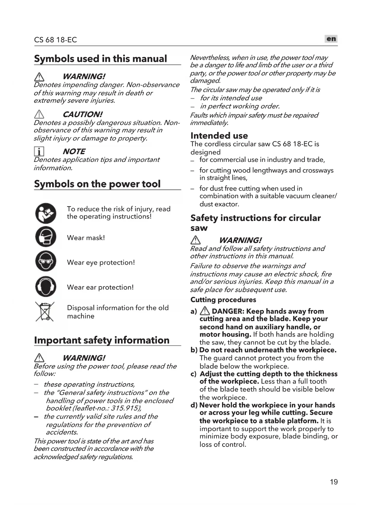
To reduce the risk of injury, read the operating instructions!

Wear mask!

Wear eye protection!

Wear ear protection!

Disposal information for the old machine
Important safety information

WARNING!
Before using the power tool, please read the follow:
these operating instructions,
the "General safety instructions" on the handling of power tools in the enclosed booklet (leaflet-no.: 315.915),
- the currently valid site rules and the regulations for the prevention of accidents.
This power tool is state of the art and has been constructed in accordance with the acknowledged safety regulations.
Nevertheless, when in use, the power tool may be a danger to life and limb of the user or a third party, or the power tool or other property may be damaged.
The circular saw may be operated only if it is
for its intended use
- in perfect working order.
Faults which impair safety must be repaired immediately.
Intended use
The cordless circular saw CS 68 18-EC is designed
for commercial use in industry and trade,
for cutting wood lengthways and crossways in straight lines,
- for dust free cutting when used in combination with a suitable vacuum cleaner/ dust exactor.
Safety instructions for circular saw

WARNING!
Read and follow all safety instructions and other instructions in this manual.
Failure to observe the warnings and instructions may cause an electric shock, fire and/or serious injuries. Keep this manual in a safe place for subsequent use.
Cutting procedures
a) DANGER: Keep hands away from cutting area and the blade. Keep your second hand on auxiliary handle, or motor housing. If both hands are holding the saw, they cannot be cut by the blade.
b) Do not reach underneath the workpiece. The guard cannot protect you from the blade below the workpiece.
c) Adjust the cutting depth to the thickness of the workpiece. Less than a full tooth of the blade teeth should be visible below the workpiece.
d) Never hold the workpiece in your hands or across your leg while cutting. Secure the workpiece to a stable platform. It is important to support the work properly to minimize body exposure, blade binding, or loss of control.
e) Hold the power tool by insulated gripping surfaces, when performing an operation where the cutting tool may contact hidden wiring or its own cord. Contact with a "live" wire will also make exposed metal parts of the power tool "live" and could give the operator an electric shock.
f) When ripping, always use a rip fence or straight edge guide. This improves the accuracy of cut and reduces the chance of blade binding.
g) Always use blades with correct size and shape (diamond versus round) of arbour holes. Blades that do not match the mounting hardware of the saw will run off-centre, causing loss of control.
h) Never use damaged or incorrect blade washers or bolt. The blade washers and bolt were specially designed for your saw, for optimum performance and safety of operation.
Kickback causes and related warnings
- kickback is a sudden reaction to a pinched, jammed or misaligned saw blade, causing an uncontrolled saw to lift up and out of the workpiece toward the operator;
when the blade is pinched or jammed tightly by the kerf closing down, the blade stalls and the motor reaction drives the unit rapidly back toward the operator; - if the blade becomes twisted or misaligned in the cut, the teeth at the back edge of the blade can dig into the top surface of the wood causing the blade to climb out of the kerf and jump back toward the operator.
Kickback is the result of saw misuse and/or incorrect operating procedures or conditions and can be avoided by taking proper precautions as given below.
a) Maintain a firm grip with both hands on the saw and position your arms to resist kickback forces. Position your body to either side of the blade, but not in line with the blade. Kickback could cause the saw to jump backwards, but kickback forces can be controlled by the operator, if proper precautions are taken.
b) When blade is binding, or when interrupting a cut for any reason, release the trigger and hold the saw motionless
in the material until the blade comes to a complete stop. Never attempt to remove the saw from the work or pull the saw backward while the blade is in motion or kickback may occur. Investigate and take corrective actions to eliminate the cause of blade binding.
c) When restarting a saw in the workpiece, centre the saw blade in the kerf so that the saw teeth are not engaged into the material. If a saw blade binds, it may walk up or kickback from the workpiece as the saw is restarted.
d) Support large panels to minimise the risk of blade pinching and kickback. Large panels tend to sag under their own weight. Supports must be placed under the panel on both sides, near the line of cut and near the edge of the panel.
e) Do not use dull or damaged blades.
Unsharpened or improperly set blades produce narrow kerf causing excessive friction, blade binding and kickback.
f) Blade depth and bevel adjusting locking levers must be tight and secure before making the cut. If blade adjustment shifts while cutting, it may cause binding and kickback.
g) Use extra caution when sawing into existing walls or other blind areas. The protruding blade may cut objects that can cause kickback.
Lower guard function
a) Check the lower guard for proper closing before each use. Do not operate the saw if the lower guard does not move freely and close instantly. Never clamp or tie the lower guard into the open position. If the saw is accidentally dropped, the lower guard may be bent. Raise the lower guard with the retracting handle and make sure it moves freely and does not touch the blade or any other part, in all angles and depths of cut.
b) Check the operation of the lower guard spring. If the guard and the spring are not operating properly, they must be serviced before use. Lower guard may operate sluggishly due to damaged parts, gummy deposits, or a build-up of debris.
c) The lower guard may be retracted manually only for special cuts such as "plunge cuts" and "compound cuts". Raise the lower guard by the retracting handle and as soon as the blade enters the material, the lower guard must be released. For all other sawing, the lower guard should operate automatically.
d) Always observe that the lower guard is covering the blade before placing the saw down on bench or floor. An unprotected, coasting blade will cause the saw to walk backwards, cutting whatever is in its path. Be aware of the time it takes for the blade to stop after switch is released.
Noise and vibration
The noise and vibration values have been determined in accordance with EN 62841.
The A-evaluated noise level of the power tool is typically:
Sound pressure level LpA 94 dB(A)
Sound power level LWA : 102 dB(A)
Uncertainty: K = 3 dB
Total vibration value:
- Emission value a_h : 2.8 m/s
Uncertainty: K = 1.5 m/s

CAUTION!
The indicated measurements refer to new power tools. Daily use causes the noise and vibration values to change.

NOTE
The vibration emission level given in this information sheet has been measured in accordance with a measurement method standardised in EN 62841 and may be used to compare one tool with another.
That the declared vibration total value(s) and the declared noise emission value(s) may also be used in a preliminary assessment of exposure.
However, if the tool is used for different applications, with different cutting accessories or poorly maintained, the vibration emission level may differ.
This may significantly increase the exposure level over the total working period.
To make an accurate estimation of the vibration exposure level, it is also necessary to take into account the times when the tool is switched off or running but not actually in use.
This may significantly decrease the exposure level over the total working period.
Identify additional safety measures to protect the operator from the effects of vibration such as: maintain the tool and the cutting accessories, keep the hands warm, organization of work patterns.

WARNING!
that the vibration and noise emissions during actual use of the power tool can differ from the declared values depending on the ways in which the tool is used especially what kind of workpiece is processed; and
of the need to identify safety measures to protect the operator that are based on an estimation of exposure in the actual conditions of use (taking account of all parts of the operating cycle such as the times when the tool is switched off and when it is running idle in addition to the trigger time).

CAUTION!
Wear ear defenders at a sound pressure above 85 dB(A).
Technical data
| Tool CS 68 18-EC | |||
| Type Circular Saw | |||
| Rated voltage Vdc 1 | 8 | ||
| No-load speed /min | Up to | 5800 | |
| Bevel capacity | ° | 0 - 56° | |
| Blade diameter | mm 19 | 0 | |
| Blade bore diameter | mm 20 | ||
| Depth of cut at 90° | mm 68 | ||
| Depth of cut at 45° | mm 50.2 | ||
| Depth of cut at 56° | mm 39 | ||
| Weight according to "EPTA Procedure 01/2003" (without battery) | kg 4.3 | ||
| Battery 18V | AP 18.0/2.5AP 18.0/5.0AP 18.0/8.0AP 18/12.0 | ||
| Weight of battery kg | AP 18.0/2.5AP 18.0/5.0AP 18.0/8.0AP 18/12.0 | 0,40,71,11,6 | |
| Charger | CA 12/18CA 18.0-LDCA 10.8/18.0 | ||
| Working Temperature | -20~40°C | ||
| Charging Temperature | 4~40°C | ||
| Storage Temperature | <50°C | ||

NOTE
To achieve better performance and use experience, the 18V 2.5Ah battery pack is not recommended.
Overview (see figure A)
The numbering of the product features refers to the illustration of the machine on the graphics page.
1 Rafter hook
2 Lock-off button
3 Trigger switch
4 Dust extraction adapter
5 Lower-guard lift lever
6 Blade stud
7 Outer blade-washer
8 Lower guard
9 LED work light
10 Bevel-preset knob
11 Calibrated bevel quadrant
12 Auxiliary handle
13 Upper guard
14 Guide rail
15 Depth bracket
16 Shaft-lock button
17 Bevel-adjustment lever
18 Bevel indicator
19 Guide slot adjustment knobs
20 Foot
21 Depth-adjustment lever
22 Blade-wrench
23 Depth-of-cut marks
24 Main handle
25 Rip fence
26 Locking nut (with spring)
27 Dust bag
Operating instructions

WARNING!
Remove the battery before carrying out any work on the power tool.
Before switching on the power tool
Unpack the power tool and accessories and check that no parts are missing or damaged.

NOTE
The batteries are not fully charged on delivery. Prior to initial operation, charge the batteries fully. Refer to the charger operating manual.
Inserting/replacing the battery (see figure B)
Press the charged battery into the power tool until it clicks into place (see figure B1).
To remove, press the release button (1.) and pull out the battery (2.) (see figure B2).

CAUTION!
When the device is not in use, protect the battery contacts. Loose metal parts may short circuit the contacts; explosion and fire hazard!
Installing the blade

WARNING!
Use only 190mm saw blades rated 5800/min (RPM) or greater. NEVER use a blade that is so thick that it prevents the outer blade washer from engaging with the flat side of the spindle. Do not use abrasive wheels
with circular saws. Using a blade not designed for the saw may result in serious personal injury and property damage.
WARNING!
Use only the recommended saw blades, for cutting wood or similar materials according EN 847-1.
WARNING!
Be sure to wear protective work gloves while handling a saw blade. The blade can injure unprotected hands.
a Take the blade wrench from its storage area.
b Press the shaft-lock button ① and use the provided blade wrench to turn the saw blade ② until the shaft-lock button engages. Continue to depress the shaft-lock button, turn the blade wrench counterclockwise and remove the blade stud and the outer washer (see figure C1).
c Make sure that the saw teeth and the arrow on the blade point in the same direction as the arrow on the lower guard.
d Retract the lower guard all the way up into the upper guard.
e Slide the blade through the slot in the foot and mount it against the inner washer on the shaft.
f Reinstall the outer washer. First finger tighten the blade stud, then tighten the blade stud 1/8 turn (45^) with the blade wrench provided (see figure C2).
i NOTE
Do not use a blade wrench with a longer handle, since it may lead to over tightening of the blade stud.
Attaching the dust extraction adapter
Check and make sure the dust extraction adapter is attached to the saw using the locking screw provided (see figure D1).
To attach a suitable vacuum hose (see figure D2)
The dust extraction adapter allows connection of a vacuum hose of D27 in inner diameter or D36 at outer diameter.
Disconnect the vacuum hose when finished cutting.
To attach the dust bag (see figure D3)
The dust extraction adapter allows connection of the dust bag.
For maximum efficiency, remove the battery pack and empty the dust bag frequently during operation.
Adjusting the cutting depth (see figure E1)
a Loosen the depth-adjustment lever.
b Hold the foot of the saw flat against the edge of the workpiece and then raise or lower the saw until the indicator mark on the depth scale aligns with the desired depth mark.
c Securely tighten the depth lock lever.
i NOTE
Check the depth setting. Not more than one tooth length of the blade should extend below the material to be cut (see figure E2).
Adjusting the cutting angle
To use the bevel-preset knob (see figure F1)
a Push the bevel-preset knob and turn it to one of the desired settings: 22.5^ , 45^ , or 56^ .
b Release the bevel-preset knob and it will serve as a travel stop when adjusting the bevel angle.
To use the bevel-adjustment lever (see figure F2)
a Loosen the bevel-adjustment lever.
b Tilt the saw as far as possible until it is blocked by the bevel-preset knob at either 22.5^ , 45^ , or 56^ . If a custom bevel angle within the selected angle range (e.g. 22.5 - 45^ ), tilt the saw until the bevel indicator is aligned with the desired angle mark on the quadrant.
c Tighten the bevel-adjustment lever.
To check the 90^ cutting angle, if necessary (see figure F3)
a Set the foot to the maximum depth. Loosen the bevel-adjustment lever, set the bevel indicator to 0^ on quadrant, retighten the
lever, and check for 90^ angle between the blade and bottom plane of foot with a square.
b Use a 2.5mm hex key (not included) to make adjustments, if necessary, by turning the small alignment screw from bottom side of the foot.
Line guide
The cutting guide notches will indicate an approximate line of cut. Use the 0^ notch as a visual guide for a straight 90^ cut. For a 45^ bevel cut, use the 45^ notch. Make sample cuts in scrap lumber to verify the actual line of cut. This will be helpful as blade types and thicknesses vary.
To ensure minimum splintering on the good side of the material to be cut, face the good side down.
- When the foot is placed on the surface of cutting material directly, use the 0^ notch and 45^ notch as shown in figure G1.
- When applying the narrow slots of the guide rail system, use the 0^ notch and 45^ notch as shown in figure G2. Check and make sure the guide rail is installed onto the wide slot of the foot when using the 45^ notch.
- When applying the wide slots of the guide rail system, use the 0^ notch and 45^ notch as shown in figure G3. Check and make sure the guide rail is removed from the wide slot of the foot when using the 0^ notch. Rotate the guide slot adjustment knobs (19) to reduce the clearance between the circular saw and the guide rail system.
Rafter hook (see figure H)
Use the hook to hang the saw from a rafter or beam or other similar secure structure for temporary storage during work.
To use, lift up the hook until it snaps into the open position.
When not in use, always lower the hook until it snaps into the closed position.

WARNING!
When the saw is hung by the hook, do not shake the saw or the object that it is hanging from. Do not hang the saw from any electrical wires. Make sure that the structure used to
hang the saw is secure. Personal injury or property damage may occur.
Only use the hook for hanging the saw. Using the hook to hang anything else could lead to serious injury.
Do not use the hook to reach another object or use the hook to support your weight in any situation.
Switching on and off (see figure 1)
The tool is equipped with a lock-off button to avoid unintentional starting.
To switch on, depress the lock-off button and squeeze the trigger switch.
To switch off, release the trigger switch.

CAUTION!
Allow the blade to come to a complete standstill before setting the saw down.
LED work light (see figure J)
The LED work light will automatically turn on with a slight squeeze of the trigger switch before the tool starts running. It will turn off approximately 10 seconds after the trigger switch is released.
a When the tool and/or battery pack becomes overloaded or too hot, the LED light will rapidly flash. Rest the tool for a while or place the tool and battery pack separately under air flow for cooling.
b The LED light will flash more slowly to indicate that the battery pack charge is at low capacity. Recharge the battery pack.
General cuts

WARNING!
Always be sure that neither hand interferes with the free movement of the lower guard.

WARNING!
After completing a cut and releasing the trigger, be aware of the necessary time it takes for the blade to come to a complete stop during coast down. Do not allow the saw to brush against your leg or side; since the lower guard is retractable, it could catch on your clothing and expose the blade. Be aware of the necessary blade exposures that exist in both the upper and lower guard areas Always hold the saw by the main handle with one hand and the auxiliary handle with the other. Maintain a firm grip with both hands
on the saw and position your arms to resist kickback forces. Position your body to either side of the blade, but not in line with the blade.
To resume cutting when cutting is interrupted, restart the saw, and allow the blade to reach full speed, re-enter the cut slowly, and resume cutting.
When cutting across the grain, the fibers of the wood tend to tear and lift. Advancing the saw slowly minimizes this effect. For a finished cut, a cross cut blade or miter blade is recommended.
Cross cuts/Rip cuts (see figure K)
The blade provided with your saw is for both cross cuts and rip cuts. Ripping is cutting lengthwise with the grain of the wood. Rip cuts are easy to do with a rip fence.
To attach a fence, insert it through slots in foot to desired width and secure with the provided locking nut.
Rip board guide (see figure L)
When rip cutting large sheets, the rip fence may not allow the desired width of cut.
Clamp or nail a straight piece of 25mm lumber to the sheet as a guide. Use the right side of the foot against the board guide.

WARNING!
Ensure that the clamps do not interfere with the free movement of the saw.
Plunge cuts (see figure M)

WARNING!
Always adjust the bevel setting to zero before making a plunge cut. Attempting a plunge cut at any other setting can result in a loss of control of the saw, which can result in serious injury.
a Remove the battery pack.
b Set the depth according to the thickness of the material to be cut.
c Attach the battery pack.
d Hold the main handle of the saw with one hand, tilt the saw forward, and rest the front of the foot on the material to be cut. Align the cutting guide notch with the line you have drawn.
e Use the lower guard lift lever to raise the lower guard until you are able to grasp and hold the auxiliary handle with the other hand.
f Position the saw with the blade just above the material to be cut. Start the motor and once the blade is fully up to speed, gradually lower the back end of saw using the front end of the foot as the hinge point.
g Release the lower-guard lift lever as soon as the blade engages the workpiece.
h Once the foot plate rests flat on the surface being cut, proceed cutting in the forward direction to the end of cut.
i Turn saw around and finish the cut in the normal manner, sawing forward. If corners of your plunge cut are not completely cut through, use a jigsaw or hand saw to finish the corners.

WARNING!
Allow blade to come to a complete stop before lifting the saw from cut. Also, never pull the saw backward since blade will climb out of the material and KICKBACK will occur.
Cutting large sheets (see figure N)
Large sheets and long boards can sag or bend, depending on their support. If you attempt to cut without leveling and properly supporting the piece, the blade will tend to bind, causing KICKBACK and extra load on the motor.
Support the panel or board close to the cut. Be sure to set the depth of the cut so that you cut through the sheet or board only and not the table or work bench.
The two-by-fours used to raise and support the work should be positioned so that the wide sides support the work and rest on the table or bench. Do not support the work with the narrow sides, as this is an unsteady arrangement. If the sheet or board to be cut is too large for a table or work bench, use the supporting two-by-fours on the floor and secure.
Maintenance and care
WARNING!
Before performing any work on the power tool, remove the battery pack from the tool.
Cleaning
CAUTION!
When cleaning with compress air, always wear goggles.
Regularly clean the power tool and ventilation slots. Frequency of cleaning is dependent on the material and duration of use. Regularly blow out the housing interior and motor with dry compressed air.
Repairs
Repairs may be carried out by an authorized customer service centre only.
Spare parts and accessories
Other accessories, in particular tools and accessories, can be found in the manufacturer's catalogues. Exploded drawings and spare-part lists can be found on our homepage: www.flex-tools.com.
Disposal information
WARNING!
Render redundant power tools unusable:
battery operated power tool by removing the battery.
EU countries only
Do not throw electric power tools into the household waste!
In accordance with the European Directive 2012/19/EU on Waste Electrical and Electronic Equipment and transposition into national law used electric power tools must be collected separately and recycled in an environmentally friendly manner.
Raw material recovery instead of waste disposal.
Device, accessories and packaging should be recycled in an environmentally friendly manner. Plastic parts are identified for recycling according to material type.
WARNING!
Do not throw batteries into the household waste, fire or water. Do not open used batteries.
EU countries only:
In accordance with Directive 2006/66/EC defective or used batteries must be recycled.
i NOTE
Please ask your dealer about disposal options!
-Declaration of Conformity
We declare under our sole responsibility that the product described under "Technical specifications" conforms to the following
standards or normative documents: EN 62841 in accordance with the regulations of the directives 2014/30/EU, 2006/42/EG, 2011/65/EU.
Responsible for technical documents:
FLEX-Elektrowerzeuge GmbH, R & D
Bahnhofstrasse 15, D-71711 Steinheim/Murr

Peter Lameli Klaus Peter Weinper Technical Head Head of Quality
Department (QD)
Declaration of Conformity
We as the manufacturer: FLEX
declare under our sole responsibility, that the product(s) described under "Technical specifications" fulfills all the relevant provisions of The Supply of Machinery
(Safety) Regulations S.I. 2008/1597 and also fulfills all the relevant provisions of the following UK Regulations:
Electromagnetic Compatibility Regulations
S.I. 2016/1091, The Restriction of the Use of Certain Hazardous Substances in Electrical and Electronic Equipment Regulations
S.I. 2012/3032 and are manufactured in accordance with the following designated Standards:
BS EN 62841-1:2015+A11:2022
BS EN 62841-2-5:2014
BS EN IEC 55014-1:2021
BS EN IEC 55014-2:2021
Place of declaration: Steinheim, Germany.
Responsible person: Peter Lameli, Technical Director - FLEX-Elektrowerkzeuge GmbH
Contact details for Great Britain: FLEX Power Tools Limited, Unit 8 Anglo Office Park, Lincoln Road, HP 12, 3RH Buckinghamshire, United Kingdom.

Peter Lameli Klaus Peter Weinper
Technical Head Head of Quality
Department (QD)
22.12.2023
Exemption from liability
The manufacturer and his representative are not liable for any damage and lost profit due to interruption in business caused by the product or by an unusable product.
The manufacturer and his representative are not liable for any damage which was caused by improper use of the product or by use of the product with products from other manufacturers.
Specifications techniques
Be sure to wear protective work gloves while handling a saw blade. The blade can injure unprotected hands.
Check the depth setting. Not more than one tooth length of the blade should extend below the material to be cut (see figure E2).
PpOoapTnON Tou oakou OKovns (BLeNc Eikova D3)
OavTantopac anoppoqnoans kovns eniptenei Tn ouvdeltaouakoukovns.
Tia meyiotn anofoon, apaipote Tn
ouotoxia natapiwv kai adieaZeTe ouxva
Tov oako okovnc kat Ta Tn diapkeia Tns
Aitoupyiac.
OTKaTe BHe3aHa peakun Ha npTnchat, 3aceHaA Hn HnpaBnHO NOpaBHeH NCK Ha TpNoHa, npuHHBaH HeKoHTpoAnpHo IOBnIraHe Ha TpNoHa Harope n HabbH OT DeTaIIa KbM OepaTopa;
KOraTO AnCKbT e npTuNCHaT nn 3ApBO 3aceHaAOT 3aTBapReHTo Ha npope3a, AnCKbT Cnnpa N ABnraTeHaTa peakun npAnBnKbYaCTpoiCTBOTO 6bp3o o6paTHO KbM OepaTopa;
aKo DNCKbT Ce ycye HnCe pa3eHTPOBa B pa3pe3a, 3b6nte Ha 3aHnra Pb6 Ha DNCKa MORaT Da Ce 3aKInHrT B rOpHaTa NOBbpxHOCT Ha DbpBOTo, pNnHBAuKn N3KaUBaHe Ha DNCKa OT BdA6hATnHaTa n OTcKaUaHe Ha3aKbM ONepaTopa.
OTkaTbTe B pe3yAtaHa 3Aoynotpe6a C TpnoHa n/nn HnnpabnHn npoceAypn nn ycOIBn Ha pa6ota n MoKe da 6bDe n36erHat KaTO Ce B3eMaT npabnHn npeDna3HN MepKn, KOINTO ca NOCOeyH AOY.
a) IopAdbpKaIte 3Apab 3axBaT c ABe pBue Ha TpNoHa n pa3nOAnKeTe PbCte Cn TaKa, Ye Da ce npOTNBONoCTABrT Ha CNIATE Ha OTkata. Pa3nOAnKeTe TAnOTO Cn OT ABete CtpaHn Ha peKeeuN AINCK, HO He Ha eHa AnHn C Hero. OTKaTbT MOKe Da DOBeDe AO TCKaUHe Ha TpNoHa Ha3aD, Ho CNaTa Ha OTkata MoKe Da ce KOHTPOInpa OT onepaTopa, aKO Ce B3eMaT IOxOAnu NpeDna3HN MepKn.
b) KOraTo AnckbTe 3aceHaA HAn Korato npeKbcBATE p3aHcTO NO HraKaBA npuHa,OCBO6oTe CnycbKa N 3aApbXkTe TpNOHa HEnoDbNXKeH B MaTePnaA,doKATo AnckbT CnPpe HanbAHO. Hnkora He ce ONNTBaIe Ta n3BaAHTe TpNOHa OT AeTaIIA HAn Da AbpNaTe TpNOHa Ha3aD,doKATO AnckbTe E B ABNXKeHHe HAn MoXe Da HAcTbIN OTkAT. PpoUyTe n ppeAnpneMeTe KopurnpaUn DeiCTBn, 3a Da OTCTpaHInTe npuHnTa 3a 3acdaHcTo Ha AnCKa.
c) Korato pectaptnape TpnoH B AeTaHa, ceHTpnpaTe pexeunA DnCK B npope3a, Taka Ye 3b6nte Ha TpNoHa Da He Ce 3aueNBaB MaTePnaA. Ako AnCKbT Ha TpNoHa 3aceAHe, Toi MoKe Da ce N3KaUn HAn Da OTCKOuN OT AeTaHa npu pectaptnapeTo Ha TpNoHa.
d) POnAaBpKaIte rOLeMn nHeAn, 3a Da CBeAeTe AO MNHmym PNCKa OT npNnNBaHe N OTKaT Ha AnCKa. TOnemnte NaHeAn ca CKAOHN DA npOBNCBaT NOA CO6CTBeHOTo CN TerAo. OOpNTe Tp8Ba Da ce NoCTABT NOA NaHeAn OT ABeTe CTpaHn, 6AN30 AO
HnHa p3aHe 6n3o Op6a Ha nHeA.
e) He n3noA3BaI Te TbHn HAn NOBpeAeHn AnCKOBe. He3aToUeHN nn HnepaBnAHO nocTaBeHN peXeU nnCKOBe npOn3BeXdAaT TeceH cpe3 npuynHrau, npeKomepHo TpHe, 3acJaHe Ha AnCKa H OTKaT.
f) 3aKaIIOUBaUNTe AOCTOBe 3a peryAnpaHe Ha dBb6OuHHaTn HAKAOHa Tp86Ba Da ca 3aTeHaN CnHyPn, npeDn Da N3BbPUnTe P8aHeTo. Ako peryAnpaHeTo Ha dNcKa Ce n3MeCTn PO BpeMe Ha p83aHe, TOBa MoKe Da npuHH 3acJaHe N OTkaT.
g)БbTe Oco6eHO BHNMaTeAHN npn p3aHe B CbIeCTByBaun CTehn NAn Apyrn cAenn 30H.N.13aBAunT ce Anck MoKe Da OTpeKe IpeAmTu, KOITo MORaT Da IIpNHyrT OTKaT.
Функцн Ha DoANHn PpeAn3NTeA
a) PpeAn BCa Ka ynotpe6a npOBepraBaTe AOHNn PpeAa3nteA 3a npABnHO 3aTBapnHe. He pa6oTe c TpnoHa, aKO DOAHnT PpeAa3nteA He ce ABNXn CBO6OaHO n Ce 3aTBapn He3a6abHO. Hnkora He 3axBaauTe n He 3aBbP3BaHT OALHn PpeAa3nteA B OTBOpeHo NOAOKeHne. Ako TpNOHBt 6bDe n3nyChat CAYaHNO, DOAHnT PpeAa3nteA MOKe Da ce OrbHe. NobnHte AOHNn PpeAa3nteA C np6npaata Ce ApbXka n Ce yBepTe, Ye Ce ABNXn CBO6OaHO n He DOKOCBA AnCKa Nn KOrTO n Da e Apyra qact, BB BCNUKN bIaN n DbA6OuHH Ha p3aHe.
b)Проверете pa60тata Ha npyxнота
Ha DOAHnЯпpeДиNTeA.Ако
прдпa3nteЯгИnpyхнота He
pa6OTЯТ пapBnHо,Te Tp8Ba Da 6b4aT
obcayxkeHnпрdnyynOTpe6a.DoAHnI
прдпa3nteЯ можe DA pa6OTu 6abHo
nopadN IOBpeDeHучсT,AnKABN
OTlaRaHnЯ ИИ NaHTpyNBaHe Ha OTAmKN.
c)ДоаннгпpeДиNTe moKe Da ce npn6npa pbuHo caMo 3a cneuaHn pa3pe3n KaTo „ВрЯЗВаши ce pa3pe3n" n „сLoXHH pa3pe3n". ПOBAnrHete DOANHn peDnA3NTe 3a npn6npaaata ce ApbXka N BeDAHara UOM AnCKbT BAE3e B MaTePnaHa,doAHnRt peDnA3NTe Tp6Ba Da ce ocbo6oAn. 3a BCnUKN ApyrN BnOBe pr3aHe DoANHngпpeDnA3NTe Tp6Ba Da pa6OTn ABTomatNoHO.
d) BnHarn c6b6I0aDaBaiTe TOBa, DOAHnT npEa3nteA da NOKpNBa DNCKa, npEa Da NoCTaBNTe TpNOHa BbpxY neKa nn NOA. He3aunTeH, ABNXeU, ce no INHePUNA INCK Ue HAKapa TpNOHa Da Ce BbPTN Ha3aA, KATo OTpR3BA BCNUKO, KOETO My IOnaADHe NO CBOr NT. BbDeTe HArCHO C BpeMeTO, Heo6XoAMO 3a CNIPAHe Ha AnCKa, CAE, OCBO6OXdaBAHe Ha npEBAIOuBaTeA.
Wymn Bn6paun
CTOINHOCTNTe Ha Wyma IN Bn6paunTe ce
onpeAETB CbOTBeTCTBNE c EN 62841.
HNBOTO Ha Wyma, OueHen no MeToA A, Ha
eAEKTPnueckna HnCTpyMeHT e o6NKHOBeHo:
- HNBO Ha 3ByKOBO HaArahe LpA: 94 dB(A)
- HNBO Ha cnAata Ha 3Byka LwA: 102 dB(A)
- HeONpeAeHocT: K = 3 dB
O6ua CToINHOCT Ha BN6paunTe:
- CToINHOCT Ha emncnTa a: 2,8 M/cek 2
- HeONpeAeHocT: K = 1,5 M/cek 2
BHUMAHNE!
Iocouehnte u3MepBaHnCe OTHacr 3a HOBn eAleKtpuueckn uHCTpyMeHTn. EKeAHeBHata yNtpe6a npuHHBa npomHa Ha CTOnHOCTnte Ha Wyma N Bn6paunTe.
i BEAEXKKA
HNBOTO Ha Bn6paunTe NOCOeyHO B TO3N HhOpMaunHe HnCTe N3MepeHO CbIaCHO MeTOA HA N3MepBaHe CTaHdapTN3npanB EN 62841 n MoKe Da ce N3NoA3Ba 3a CpaBnBaHe Ha eAnH NHCTpyMeHT CApYr. DeKApnpaHaT a O67a cToHocT(u) Ha Bn6paunTe N O6RBeHata(nte) cToHocT(u) Ha WymOBnTe emCnN CbUo MOrat Da 6bDat N3NoA3BaHn Pn PpeDabnPteHa OueHka Ha EKCnO3nUyra.
BbnpkntoBa,akoHCTpyMeHTc Ce
n3noA3Ba 3a pa3AnuHN npNLOXKeHna, C
pa3AnuHN pexKeun npHaAeXHOCTn NAn
AIOo NOAdbPkaHn, HNBOTO Ha n3AbYBaHe Ha
Bn6paun MoKe Da ce pa3Anuaba.
ToBa MoKe 3HaunTeAHO Da yBcAnuH HNBOTo Ha n3laRaHe 3a ceA nnepnOd Ha pa6Ota. 3a Da HnPaBnte ToUHa OueHka Ha HNBOTO Ha n3laRaHe Ha Bn6paun, Heo6xOAnMo e CbIo Da B3eMeTe NOD BHImaHne BpeMeHaTa B KOnTO INCTpyMeHTbT e N3KIAUoyen IAN
pa6OTn, HO B AeIcTBnTeAHOCT He CE n3NOA3Ba.
Toba moKe 3HaunTeAHO da HaMaAn HnBOTO Ha n3aaraHe 3a ueAЯ nepnoA ha pa6ota.
OnpedeTe DOBbHHTeHn MepKn 3a 6e3oNaChoc 3a 3aunTa Ha onepaTopo OT eEKTITE Ha Bn6paunTE KaTO: NOA pKka Ha INCTpyMeNTa n peKeuNTe akcecoapn, NOA bPkaHe Ha pBeTe TOnAN, OprAHN3aun Ha MoDeIte Ha pa6ota.

PPEAYNPEXAEHVE!
- ue Bn6paunTe n WymOBNTe emncn no BpeMe Ha AeInCTBnTEA HOTO U3NOA3BaHe Ha eEeKtpOnHCTpyMeHTa MoTa Da ce pa3AnuBaT OT AeKApnpaHNTe CToHOCTH B 3aBnCmOCT OT HaUnHNTe, NO KONTo Ce U3NoA3Ba INHCTpyMeHTbT, Oco6eHO KaKbB BuA DeTaA N Ce o6pa6oTBA; n
- 3a Heo6xo4mOCTTa OT n4eHTnHcnpaHe Ha MepKu 3a 6e30nacHOCT 3a 3aunTu Ha OnepaTopa, KOnTO ce OCHOBaT Ha OueHka Ha EKCNO3nUra Ta Pn AeiCTBNTeAHNTE yCAOBnHa yNtpe6a (Kato Ce B3emat PpeABnA BCNUKu Yactn Ha pa6OTHnZkBn, KaTo HApPmEp BpEmTo, KOrato INHCTpyMeHTbTe U3KAIOyeh N KOrato pa6OTn Ha npa3EH XoA, BDOJIbAHHeHne KbM BpEmTo 3a 3aDeIcTBaHe).

BHVMAHME!
Hocete aHTnfoHN npn 3ByKOBO HaAraHe HaA 85 dB(A).
TexHnueckn DaHHN
AaTepbT 3a N3BnUaHe Ha npax NO3BOIBA CBbp3BaHETO Ha Mapkyu 3a npaxOCmyKaUka C BbTppeWeH dNaMeTbp D27 nn BbHweH dNaMeTbp D36.
CleA npiklouBaHe Ha p3aHTo pa3KaueTe Mapkyua 3a npaxocMykaUka.
3a 3akpenBaHe Ha Top6nUkaTa 3a npax (BnxTe fHrgypa D3)
AaTepbT 3a n3BnUyHe Ha npax n03BOIyBa CBbp3BaHeto Ha TOp6uKa 3a npax.
3a Da NOCTHHeTe MaKcMmaHa eΦeKTNBHOCT, n3BaJdaIte 6aTepeNra n n3npa3BaIte Top6uKaTa 3a npax yeCTo no BpeMe Ha pa6ota.
Perynpahe Ha b60nHaTa Ha p3aHe (BxKTe cnrgpa E1)
a Pa3xa6eTe AocTa 3a peryIuPaHe Ha bA6OuHata.
b ApbKTe KpaKa Ha TpNoHa NLOCKO KbM p6a Ha 6pa6oTBaHn AetauN CaeT TOBa NOBAnrHeTe Hn CNyChTe TpNoHa, OOKATO INAnkatoPHTa MapKnPOBka Ha cKaAata 3a Db6OuHn Ce n3paBn C JeHaHaTa MapKnPOBka 3a Db6OuHa.
c 3aTeHHeTe 3ApaBO AocTa 3a 3aKIOUBaHe Ha △bA6OuHaTa.
i BEAEXKKA
IpoBepete HactponKaTa HaA b6OuHata. AbxnHaTa Ha He NoBeue OTe eAn 3b6 Ha peKeunr Anck He Tp6Ba Da ce N3aBa nOa peKeunr MaTePnaA (BxKTe fNrypa E2).
PeryIpaHe Ha bIbIa Ha p3aHe H3noA3BaHe Ha KonueTo 3a npEaBapnteHa HaCTpoIka Ha cKocBaHeTo (BHXTe fNrgpa F1)
a HaTnCHTe KOnUeTo 3a npEaBapNTeHa NaCTpoNka Ha cKocBaHTo n rO 3aBbPTeTe AO eAHa OT XeAaHHe NaCTpOuKn: 22,5°, 45^ nn 56°.
b Ocbo6oTe KOnueTo 3a npeAbaPnteHa HactpoiKa Ha cKocBaHeTo I TO ue C LyKu KaTO orpaHnHTeHa ABXKeHneTo npu peryInpaHe Ha bBlaHa cKocBaHe.
N3no3BaHe Ha LoCTa 3a peryAnpaHe HaCKoCABaHeto (BnXTe fHyrgypa F2)
a Pa3xa6eTe AocTa 3a peryIpaHe Ha CKOcRABaHTo.
b HaKLoHHe TpNoHa Bb3MoXHo HaMHoro,doKaTo He 6bDe 6IoKupaH OT KOnyTe 3a npEaBapnteHa hAcTpoNka HaCKoCBAHeTo Ha 22.5°,45° nAn 56°.Ako e Heo6xoAM NOTpe6nTeAChKn bIbHa CKoCBAHe B paMKte Ha n36paHna bIaOB dHaana3OH (HaNP.22.5-45°),HaKLoHete TpNoHa,doKaTO INdNKaTopbT 3a CKoCBAHe Ce n3paBHc M aPknOpOBkata 3a JKeAHHa BbA Bbpxv KBaDpaHTa.
c 3aTeHHe TocTa 3a peryAnpaHe Ha CKOcRABaHETo.
3a npOBepka Ha bIbIa Ha pIaHe 90^ ,ako e Heo6xOaMo (BnXTe fNrgya F3)
a HaCTpoIte KpaKa Ha MaKcImMaHaHaTa Abl6OuHnA. Pa3Xla6Te AocTa 3a peryInpaHe Ha CKoCBAHeTo, HAcTpoIte INHAnKaTopa 3a CKoCBAHe Ha 0^ B KBaApHTa, 3aTeHHeTe OTHOBO AocTa I npOBepeTe C KBaPaT DaAN bBbT MeJky peKeunr Anck N DOHaTa paBHNHa Ha Kpaka e 90^
b 3no3BaTe 2,5-MnAmMeTPOB
WecTOCTeHEn KIOU (He e BKAIOueH B
KOMNKeTA), 3a Da HaNPaBNTe KOpeKcUN,
aKO e Heo6XoAMO, KaTO 3aBbPtNTe
MaKNy BNHT 3a NOpaBHBaHe OT DOHaTa
CTpaHa Ha KpaKa.
Anheen Boidaay
Hape3nTe Ha BOdaa 3a p3aHe noka3BaT np6An3nTeHa AnHna Ha p3aHe.
N3noA3BaIte Hape3a 3a 0^ kaTo BN3yaAeH opneHTnp 3a npaBOAnHeNoHO p3aHe Ha 90^ .3a p3aHe NObTBbA 45^ n3NOA3BaIte Hape3a 3a 45^ .HanpaBete npo6n pa3pe3n B OTnAbueh AbpBeH MaTePnaA, 3a Da npOBepnte DeiCTBnTeHaTa ANHna Ha p3aHe.ToBa Iue BN 6bDeOT nOla, TbN KaTO BnDoBeTe N De6eAnHnTe Ha peKeuNTe DnCKOBce pa3AnuBaT.
3a Da ce rapaHTnpa MHHMaHNo pa3eNbaHe Ha do6pata cTpaHa Ha p3aHn MaTePna, 06bpe Tdo6pata cTpaHa HADOy.
Korato KpaKbTe noCTaBeH AnpeKTHO Bbpxy NOBbpXHOCTTa Ha OTP3BaHn MaTePnaA, n3NoA3BaIte Hape3nte 3a 0^ n 45^ , kaTo e noka3aHo Ha @nIpya G1.
Korato n3noA3BaTe TcHnTe npope3n Ha cnCTemata 3a HnnpabBnBaunTe peAcn, n3noA3BaIte Hape3nTe 3a 0^ n 45^ ,KaKTo e noka3aHO Ha nHypTa G2. IpOBepeTe n ce yBepete, Ye HnnpabBnBaUaTpeAca e MOHTupaHa B WnPOKn npope3 Ha KpaKa, Korato n3noA3BaTe Hape3a 3a 45^
Korato npnlaarate shnpoknte npope3n Ha cnCTemata 3a HnnpablaBaunte peacn, n3noan3Baute hape3ne 3a 0^ n 45^ ,kakto e noka3aHO ha fngypa G3. POBepete n ce ybepete, ye HnnpablaBaata peLca e n3BaedeHa OT shnpOKn npope3 Ha Kpaka, KOrato n3noan3BaTe hape3a 3a 0^ 3abptete konyeta 3a perynaphe Ha HnnpablaBaunte npope3n (19), 3a da HaMaNTe XAnhata MeJkyAarpHn TpnoH n CnCTemata OT HnnpablaBaunpeACn.
Kyka 3a rpeu (Bnxte fnrypa H)
N3noA3BaIte Kykata, 3a Da OKaunTe TpnoHa Ha HappeHnK, rpei nn Apyra noo6Ha cnrypha KOHCTpyKUnr 3a BpeMeHHO cbxpaHeHne nO BpeMe Ha pa6ota.
3a da n3noA3BaTe, NOBAnrHeTe KyKaTa, DOKaTo UpaKHe B OTBOpeHo NIOXKeHne.
Korato He ce n3noA3Ba, BnHaRn cnyckaIte KykaTa, dOKaTO upaKHe B 3aTbOpeHo NOLOXKeHne.
I PEAYIPEXKAEHNE!
Korato TpnoHbTe oKaueH Ha Kykata, He
pa3kaaIte TpnoHa Hn IpeMeta, Ha
KOHTo e OkaueH. He 3akauaIte TpnoHa
Ha ealeKtpuYeCKn npOBaHNu. YBepete
ce, Ye KOHCTpyKzraTa, n3NoA3BaHa 3a
OKaUBaHe Ha TpnoHa, e cnrypha. Bb3MOxHo
e Da Bb3HNKHAT TeAECHN NOBpeDu Nn
MaTePnaAHN uetN.
U3NOA3BaIte Kykata cAmO 3a OKaUBAHe
Ha TpnoHa. U3NoA3BaHeto Ha Kykata 3a
OKaUBaHe Ha ApyrN IpeMetn MoKe Da
AOBeDe AO cepNo3Hn HapAHBaHn.
B HnKaKbB CnyaH He n3NoA3BaIte Kykata,
3a Da AocTURHeT Apyr IpeMet, HnTO 3a Da
IOAdbPkaTe TERATO Cu.
BkIoUbaHe N n3KIAIOUbaHe (BnXTe fNrgypa I)
HCTpyMeHTbTe cHa6aEHc 6yToH 3a 3aKAnOuBaHe, 3a Da ce n36eHrHe HeBOAnHO CTapTnpaHe.
3a Da BKAIOUHTe, HATNCHETe NpBO 6yTOHa 3a 3aKIAOUBaHe, CKeT OBA HATNCHETe CNyCbKa npeBKAIOUBAteA.
3a Da n3KIOUHTe,OCBO6oTe cnycbKa npebkAOyBaTeA.
BHUMAHVE!
OctabeteAUCKaAa Cnpe HAnbAHO, PpeAHa a OCTaBHTe TpnoHa.
LED pa6oTHa CBetAnHa (BnXtTe cnrgpa J)
LED pa6oTHaTa CBeTAnHa aBToMaTuHcCe BkIoUbA C AeKo HaTnCKaHe Ha CnycbKa npEbkIOuBaTeA, PpeiNnHCTpyMeHTbTda3aOnue pa6ota. Ta Ce n3kIoUba OKoAo 10 cekyHdN cIeD OTnyckaHe Ha cnycbKa npEbkIOuBaTeA.
a LED pa6oTHata CBeTAnHa ige Mna 6bp30, KOrato INHCTpyMeHTbT N/INN 6aTepeyra ce npetOBaprNn PpeKaaleHo ce HaropeuT. OcTabe Te INHCTpyMeHTa 3a IN3BecTHO BpeMe Nn NOCTaBeTe INHCTpyMeHTa n akymyAtoPHaTa 6aTepeNr OTdEALHO NOD Bb3AyuWeH NOTOK, 3a Da CE OXAAAT.
b LED cBeTAnHaTa ige Mna No-6aBHO, 3a Da NOKaKe, Ye HNBOTo Ha 3apA, Ha 6aTePnra e HnckO. Ppe3apeDeTe akymyIaTOPHaTa 6aTePnra.
O6po p83aHe
IPEyIPEXAEHNE!
BnHa nCe yBepaHte,Ye HNKoAOTpBcTe Bn He npeHu Ha CBO6OaHOTo ABXKeHHe Ha AOHNrPipea3nteA.
I PEAYINPEXHEHNE!
CleKaTo 3aBbPwITE p3aHETO nOCBO6oAHTe CnycbKa, O6bPHeTe BHNMaHHe Ha Heo6xoAUMOTO BpeMe, Koeto e Heo6xOAMo Ha peKeeuA DnCK Da Cnpe HAnbHO NO BpeMe Ha ABHXeHneTO NnHepu. He No3BOABAIte TpnoHBtAa Ce AOnIPA AO KpaKa IAN CTpaHaTbN; TbN KaTO AOHNr PpeAa3ntEa E npu6npaUcCe, Toi MoKe Da Ce 3aKaaUn 3a ApexNTe BN N Da NOKaepeKeeuA DnCK. Cbo6pa3ete ce C Heo6xoAUMITE N3dAbAHn Ha peKeeuA DnCK, KOINTO CbIeCTByBaT KaKTO B rOpHaTa, TaKa IN B AOHAta 3aUNTHa 30Ha.
BnHa ndpkTe TpnoHa 3a rAabHata
pbkoxbatka c eHaT a pbKa, a Cpyrata - 3a
cnomaraTeHaTpaPkoXBtka. IoAbpkaIte
3apab 3axBaT C DBe pBcE Ha TpnoHa n
pa3noLoXeTe PbCte CN TaKa, ye Da ce
npOTNBONCTABRT Ha CNNTe Ha OTKaTA.
Pa3noLoXeTe TAnOTo CN OT dBete CTpaHN Ha
peXeunr AnCK, HO He Ha eDHa AINHn C Hero.
3a Da Bb306HOBIne pr3aHETo npi
npekbcBaHeto My, pectaptnupaTe TpnoHa n
octabete peXeunr Anck Da DOCTnRHe PbANHa
CKOPoCT, HabAe3Te OTHOB B pa3pe3a 6abHo
N Bb306HOBete P3aHETo.
Ipn Hanpeuho p3aHe BAAkHaTa Ha
AbpBOTO ce pa3KbCBat N NOBAnrT. BaBHOTO
PnAdbNKBaHe Ha TpNOHa CBexKa DO
MHHmym To3n eEeKT. 3a OKOHuaTeAHO
p3aHe npenOpbUba DNCK 3a HanpeuHo
p3aHe NN dNCK 3a CKoCBAHe.
HanpeuHn pa3pe3n/npope3n pa3pe3n (BnxKTe fngrypa K)
PexeunrA Dnck, PpeOCTaBeH C TpnoHa, e npedha3HaueH KaKTo 3a HappeHn, TaKa n 3a npope3Hn pa3pe3n. Ppopra3BaHeTo e HaAdbXHO p3aHe NO NOCOKa HA BAAkHaTa Ha ADbPBeCnHaTc. C NOMoUta Ha ORpaHnUteA 3a pr3aHe NO dBAXnHa p3aHeTo ce N3BbPwBa AecHo. 3a Da 3akpenTe orpaHnUteA, NoCTaBeTe ro npes npope3nte B Kpaka Do JKeAHaTa
HINHa HrO 3aKpeNeTe C npEoCTaBeHaTa
NkCnpaua raKa.
Bodau 3a p3aHe Ha Abckn (Bnxte fnpypa L)
Pn npopra3BaHe Ha roAeMu AnCTObe orpaHnUHTeAaT Ha pr3aHeTo MoKe Da He PO3BOABya JeAaHaTa 7uPnHa Ha p3aHe.
3aterheTe HAn 3aKOBete C npoHn npaBO napue DbpeBHe MaTePnaA C pa3Mep 25 MM KbM AnCTa KaTO BODaU. N3noA3BaIe AChata CTpaHa Ha Kpaka CpeuY BoDaau 3a DbCKn.
IPEAYIPPEKAEHNEI
YBepete ce, ye cKoBte He nppeuat Ha CBO6OaHOTo ABNXeHHe Ha TpNoHa.
Pa3pe3n c Bp83BaHe (BnXkTe ursypa M)
IPEyYPEXKAEHNE!
BnHa n perya npaTe hactpoKaTa Ha CKocBaHTo Ha Hya, IpeAn Da N3BbPwnte Pra3aHe C Bp3BaHe. OnntbT 3a P3aHe C Bp3BaHe npn BCa Apyra HactpoKa MoKe Da DOBeDe AO 3ary6a Ha KOHTPOA Ha TpNOHa, KOeTO MoKe Da DOBeDe AO cepNo3HO HapaHbAHe.
a PpemaxheTe akymyIaTOPHaTa 6aTepeia.
b HactpoTe A6OuHaTa cnopeA De6eAnHaTa Ha p3aHn MaTePnaA.
c PnKpeNeTe aKymyIaTopHaTa 6aTePnIa.
d ApbKTe rAaBHata pBkoXBtKa Ha TpnoHa c eHa pKa, HAKoHete TpNoHa Hanpei n OnpeTe npEHaTa Yact Ha KpaKa Bbpxy MaTePnAA, KOITo ige ce peXke. IopapBHeTe kAe6a Ha BOda4a 3a P3aHe C NaheptHaTAt AHHN.
e N3noA3BaIte AocTa 3a NOBnraHe Ha DOAHnI ppeAa3ntTe, 3a Da IOBnHete DOAHnI ppeAa3ntTe, OKaTO ycneete Da XbaHeTe I 3aDbPjKnte CnOMaTaeHaHaTa pbKOXBaTKa C ApyraTa cn PbKa.
f NocTabeTe TpnoHa c octpneTo TOUHO HaMaTePnAa, KOTo ue ce peKe. CtapTnpaIte ABnTaTeA n CaeA KaTo peKeuRrDnCK DOCTnHRe PbAnHa CKOpOcT, NoCTepeHHo CnYChTe 3aDHnKpaH a TpNoHa, KATO n3NO3BaTe ppeHnKpaH Na Kpaka KATO WapHnPa ToUka.
g Ocbo6oTe AocTa 3a NOBAnrAHe Ha DOAHnI PpeApa3nTeA BeHaRa 1OM peKeuNT AnCK ce DOnpe Do
06pa6oTbaHnA DeTaIa.
h CKeA KaTo NIoOaTa 3a KpaKa AerHe paBHomepHO BbPxy NOBbPxHocTtHa Ha p3aHe, npoAbXKeTe Da peKKeTe B nocKa HnpeA DO KpaHa P3aHeto.
i 3aBbptete TpnoHa n 3aBbPwete p3aHTo nO oNuaHnHaunH, KaTo peKeTe HnpeA. Ako bTnTe Ha pa3pe3a C Bp3BaHe He ca HanbAoHn3p3aHn, N3NoA3BaIte npo6oDeH TpnoH nn PbueH TpNOH, 3a Da 3aBbPwnte bTnTe.

IPEAYNPEXKAEHME!
U3yaKaIte peKeuN AUC K Da Cnpe HaHbAHO, npEa DA BAnrHeTe TpNOHa OT MCTOTO Ha p3aHe. Cbso TaKa HNKora He N3AbpNaTepNOHa Ha3a, TbN KaTO peKeuNATnCK ige N3CKOuN OT MaTePnaA u Iue Bb3HnKHe OTKAT.
Prahe Ha roAeMu AnCTObe (BnKTe fHrgypa N)
TOnEMNTAUCTOBENABaHTeBbCKN MOrat Da npOBnCHAT NAn Da ce OrBaHAT B 3aBNCIMOCT OT NOdnapHeTo NM.AKOce ONHTaTe Da peKeTe,6e3 Da CTe N3paBHNAn N NoDInpeAn npabnHO DeTaIa,peXeunrTJe HMa CKAOHHoCT Da ce 3aKLeuBa,KoETo ige DOBeDe DoOTKAT NdoBANHTeHn Ho HAtOBapBaHe Ha ABnraTeA.
Iopdkpenete nahea ann Dbckata 6an3o do pa3pe3a. He 3a6paBnTe da hactponTe ab60uHaTa Ha p3aHe Taka, ye da peKeTe camo npe3 Ancta nn Dbckata, a He npe3 Macata nn pa6OTHn IANT.
ABeTe YeTBOPKn, n3NoA3BaHn 3a NOBAnraHe n NODbPkaHe Ha pa6oTaT, Tp6Ba Da ce NoCTaBt TaKa, Ye WnPOknte CTrpaHn Da NODbPkaT DeTaNla N Da ce ONnpaT Ha Macata Nn Nnota. He NODnnpaTe DeTaNla C TeCHNTe CTrpaHn, TbN KATO TOBa e HecTa6NHO NIOXKeHne. AKO AnCTbT Nn DbCKaTa, KOINTO Tp6Ba Da ce OTpeKAT, Ca TBbpDe rOAmn 3a Maca Nn pa6oTeH NLoT, n3NoA3BaYte NODnOpHnTe DBe YeTBOPKn Ha NODa Nr 3akpenete.
PoaApbXka n PoinaRaHe Ha rpnx

IPEAYNPEXKDEHME!
OctpaheTe 6atepuTAt O typeAa, npEAnAa
n3BbPwnte KaKBaTO n Da 6HNo pa6Ota no eAekTpnuyeckna ype4.
Почистван.

BHUMAHME!
Korato NOUCTBaTe CbC CrbCTeH Bb34yX,
BnHaHn Hocete PpeAa3HN OuHa.
PeOBOHO NOUCTBaIte eAeKTpNueCKn
NHCTpyMeHT N BEHTNaauOHnTE OTBOPN.
YeCTOTATA Ha NOUCTBaHe 3aBnCn OT
MaTePnaAa N pOaBxKnteALHOCTTa Ha pa6ota.
IepNoAnuHo n34yXbaIte BbTpeWnOCTTa Ha
KOpNyCa N ABnraTeAa Cbc CyxC CrbCTeH Bb34yX.
PemOH
PemOHHTHnTe AeHocTn Tp6Ba Da ce
N3BbPWBaT cAmO OT OToPi3npaH ceHTbp 3a
06cayXbaHe Ha KAneHTn.
Pe3epBn qactn n akcecoapn
3a dpyr n akcecoapn, no-KoHkpeTHO INHCTpyMeHTN u akcecoapn, BNXTe KaTAL03NTe Ha npOn3BOAnTeA. YepTeXn B pa3rLo6eH BVd N CnncBcun Ha pe3epBHNte YaCTN MoKTe Da HamePnte Ha Hauata HauaHa CTpaHnua: www.flex-tools.com.
HΦopMaçnla 3a n3XbρʌHe

IPEAYNPEXKAEHME!
HanpaBete n3AunwhnTe eAekTpnuyeckn HNCTpyMeHTn Heu3NOA3BaEMN:
pa6oteuHTe Ha 6atepna eAektpnueckn HNCTpyMeHTn Upe3 npemaxBaHe Ha 6atepna.

Cama 3a ctpaHn oT EC He n3XbPAAIe eAekTpueckn HNCTpyMeHTN BDOMaKNHCKNte
OTnAdbu!
B cbOTbETCTBnE c EbponeNcKa dnpeKTNBa 2012/19/EC 3a otnaDbuHo eAeKtpuecko n eAeKTPoHNo o6OpyDaHe n HeHOTO OTpa3RABaHe B HaunOHAnHTe 3aKOnn, N3POAN3BaHNTe eAeKTPnupeCKn INHCTpyMeHTn Tp8Ba Da 6bDat Cb6puHn OTdEAnHO n peunKAnpaHn NO cbO6pa3EH C ONa3BaHeTo Ha OKoAHHaTa CpeDa HauH.

PeunKAnpaIte CypOBHHTe, BMeCTO Da Hn N3XbPaIte Ha OTNaDbIHTe.
UcpoiCTBa, akcecoapn n ONAKOBN Tp6Ba Da 6bDaT peuKInpaHn No cbo6pa3EH C Ona3BaHeTo Ha OKoHaTa CpeHaHuH.
IaTMacOBnTe yactn ca 06o3HaueHn 3a peuKnnpaHe cnopeTnHa MaTePnaAa.
I PEAYIPEXKAEHNE!
He n3XbpaIte 6aTepuNTe B DAOMaKnHCKnO TnaBk,OrbH nn BOa. He OTbaprnte n3PON3BaHNTe 6aTepn.
Camo 3a ctpaHn ot EC:
BcbOTBeTCTBnecAnepeKtNbBa 2006/66/EO
AeKTHHe Hn H3No3BaHnTe 6aTepn Tp6Ba Da 6bDaT peuNKAnpaHn.
i BEAEXKKA
Moa, nonntaute cB0r TbproBeu 3a
Bb3MOXHOCTNE 3a N3XBbPAHHe!
C-KeKlapaun3a
CbotBetCTBne
AeknapaMe Ha CBOB OTROBOPHOCT,
Ye npoAkykTbT OnIcaH B, "TexHnueeCKN
CneuNΦnKaun"OTROBapHa CAnHNTe
CTaHApTu NAn HOpMaTnBHN OOKyMeHTN:
EN 62841 B cBOTBeTCTBnE c peYaunTe
Ha AnpeKtNBn 2014/30/EC, 2006/42/EO,
2011/65/EC.
OTROBOpeH 3a TexHHueCKnTe DOkymeHTN:
HactoIue HCTpyKuIN NO 3KcNAYaTaUIN;
- 06uine uHCTpykunno TExnke 6e3oNaChocTN npu o6paueHN C 3AeKTPoHHCTpyMeHTaMn B pNnaraemom 6yKaTe (6yKaT N° 315.915);
- npabna, AeICTByIOune B pa6oey 3OHe n Mepbl NO ppeoTbpaueHnIO Hechacthbx CAYuaEB.
3TOT 3AeKtpOnHCTpyMeHT OTBeyaET cambIM COBpeMeHHbIM Tpe6OBaHnM n 6blcKoHCTpyuPoBaH B COOTBeTCTBnC 6OSeepn3HaHHbIMn PpaBnAmN 6e3onacHOCTn.
TeM He MeHee, npn HcNoB3OBaHnn 3AekTpOHCTpyMeHT MoKeT PpeAcTaBArTB ONaCHOCTb AAR KIN3HN N KOHeuHOCTe IIOAB3OBaTeA nn TpeBnx Anu. Kpome TorO, 3AekTpOHCTpyMeHT n Apyroe MMyueCTBO MOryt 6blb NOBpeKdEhl.
LnpkyjarpHyo NnIy MoXHO 3KcJI yaTnpOBaTb TOnbKO:
- NO Ha3HaueHnIO;
BuaaHOMpa6oeycMoCCTOHHN.
HeucnpabHoctn, KOtOpbIE BAHAOT Ha 6e3oNaCHOCTb, A0Akhbl 6blTb HEmeAeHHO yCTpaHeHbl.
06laactb npimehenna
AkkMyTOpHnUnpKyIaPnHa nna CS 68 18-EC npedHa3HaueHa:
- KOMMepueckoro NcnoAb3OBAHnB npomblaeHHOCTN TOPROBe;
-ДЯпразмОпpoAoBHOи NOpepeHOn pe3KN ApeBeCnHbl; - 6ecnbHOB pe3Kn B COyehnn C NOxOaUM PbIeCOCOM Nn PbIeYAOBNTeAm.
AIA NOBbIeHn Ipon3BOaNTeABHOCTN UyAO6CTBa NCIOAb3OBaHn He peKOMeHApETcN CNOAb3OBA Tb aKKMyAraTOpHyio 6aTapeo 18 B2,5A.
O63op (cM. Pnc. A)
HymepaunyacteynyctpoictbaOTHOCTCA K NAAIOCTpaunm yctpoiCTBa Ha cTpaHnue CXEM.
1 Kpiok AAR NOABeWNBaHnA
2 Khonka 6AnKnpOBKn
3 KypkoBbI BbIKAIOuTeAb
4 AaTep nbIeYIaBbIbIouoJyCTpOcTBa
5 Pbyar noAbema HnXhero uNTka
6 WnnaBka Ancka
7 BheHnHa 6a 6a nIbHorO dNcKa
8 HxHHHn uNTOK
9 CBeToAHOAnHa pa6oay IOncBETka
10 Pyuka npedyctaHOBKn yrLa ckoca
11 KaH6pOBaHHa 乌kaAa cKoca
12 BcnoMoraTeIbHa pyKoRTka
13 BepxHn nHTok
14 Hapablaioua
15 KpoHwTeH peryAnpOBKn rAy6nHbI
16 Khonka 6AOKnpoBKn BaAa
17 Pbyar peryanpoBkn yra ckoca
18 INHAnKaTOp yrAa ckOca
19 PuyknperyanpoBkn HnpaBIAIOx OTBepctn
20 OchoBaHne
21 Pbyar peryuAnpoBkn rAynHbI
22 KaIOU AAR NAAbHbIX AnCKOB
23 MeTkI rAy6HbI npOnnHa
24 OchOBHЯ pyKoTka
25 HanpaBIAIOUaIaHka
26 Ctonopnra raKa (c npyKnHoi)
27 Пьialeсборнik
Инструкция по заци.
IPEAYNPEXKAEHNEI
IpeaBbIOAHeHEm AIO6bIX pa6OT nO 06cayxHBaHIO 3AekTpOHCTpyMeHTa N3BAeKaIte aKKyMyAITOp.
Ipea BkAIOUeHnem 3AekTpOHNCTpymEnta
Pacnakynte 3AekTponHCTpyMeHT npHaAExKHOCTN y6eAnTEcB, YTO BCE AeTaAN IMeOTcB HAAuH N He NOBpeXdEhl.
i IPNMEYAHNE
AkkymyAToPbI NOCTaBAJOTc yactuHO 3apjKeHHbIMN. Ipeed hauaIom pa6oTbI NnHOCTbIO 3aprAnTe aKKymyAToPbI. CM. pyKOBOAcTBo IIO 3KCIAYaTaUH 3apraHoro yCTpOInCTBa.
YCTaHOBka N 3aMeHa aKKymyATopa (cM. Pnc. B)
BCTaBbTe 3apJxKeHHbI aKKyMyAITOp B 3AeKTPoHnHCTpyMeHT DO IeAUKa (CM. Pnc.B1).
YTo6bI n3Baeuy aKKyMyAITOp,HaXMnTe KHOKNy fNkcaun (1) n n3BaeKeNTe ero (2) (cm.Pnc.B2).
BHUMAHVE!
Korda yctpoiCTBO He nCNOb3yeTc, 3aKpbBaHTe KOHTaKTbI aKKyMylAToPA. MetaAnueckne npEaMetbMOrY 3aMKHyTb KOHTaKTbI, Bpe3yAbTaTe Yero BO3MOxKeH B3pbIB Nn NoXap!
yctahobka pexkyuero 3Alemehta
IPEAYIPEXKAEHNEI
Ncno3yte TObKO NnBhble ANCN
Anametpom 190 MM, paccuHTaHHbIe Ha
5800 o6/MnH nn Bblwe. HIKO4A He
Ncno3yTe AACKn TaKoT OaunHbI, YTO6bl
OHn HE PO3BOAA BHeUHe NsHBe AACKa
BOITN B 3auePAnEHN C PLoCKoN CTOpOHON
WnnHaeJr. He NCNO3yTe C UnpKvApRhBMn
PiAAA n 6pa3NBbIe Kpyr. NcnoA3OBaHne
AACKa, He npEHa3HaueHHoro AIA NnAbI,
MOkEt npVBecTI K cepbe3HbIM TpaBMam n
NoBpeJeHIO NMyueCTBa.

IPEAYNPEXKAEHNE!
IcnoA63ynteToA6KOpeKOMeHDoBaHHbIE NnA6HbIeA6CKN,IIpeAHa3HaueHHbIeAIA pe3KN ApeBecuHbI IAAaHaONuHbIX MaTePnaOIB COOTBeTCTBUN C EN 847-1.

IPEyINPEKAEHNE!
Ipn pa6ote C nHbIM Anckom O6a3aTeAho HaedeBaHTe 3aunTHbIe nepaATKn. Anck MoKet npaHnTb He3aunueHHbIe pyKN.
a Bo3bMnte KAIou AAR NnAbHbIX AnCKOB n3 Mecta xpaHeHH.
b HaKMTe KhoNky 6oKnPOBKn Bala 1 n c NOMOsbIO npNlaRaemoro KAIOUa DAЯ NNAbHbIX AnCKOB NOBepHNTe NAnbHbI INCK 2do fNKcauIN KhoNkn 6oKnPOBKn BAa. IpOdoXkay HaxmAtb Ha KhoNky 6oKnPOBKn BAa, NOBepHNTe KIOUdAЯ NNAbHbIX AnCKOB IpOTNB YacOBOn CTpeAKn IN CHMnTE WIIaNbKy AnCKa N BHeShHIO Oaib6y (cM.Pnc.C1).
c Y6eAnTEcB, yTO 3y6bI NnAbl n CTpeKa Ha AnCKe HAnpaBHeHb B Ty Xe CTOpOHy, yTO n CTpeKa Ha HnXkHem UNTke.
d BtAHnTe HxHnI ΚnTOK Do ynpa B BepxHnI ΚnTOK.
e BCTaBbTe Anck Yepe3 npope3b BV OCHOBaHm N yCTaHOBnTe ero Ha BHyTpeHHIO 7aM6y Ha BaIy.
f YcTaHOBnTe Ha MeCTO BHeUHIO UaI6y. Chaua 3aTHNTE uINbky dNcKa naBcAmu, 3aTeM 3aTHNte ee Ha 1/8 o6Opota (45^) c NOMoBIO npnaaraemoro KAIOUa AAnBHBIX DnCKOB (cm.Pnc.C2).

ПРИМЕЧАНС
He nCnoB3yInTe KIAOc C 60Aee AAnHHoH pyuKo, TaK KaK 3TO MoXeT npNBecTu K ype3MePHoN 3aTAAKKe UINNAbKN AnCKa.
YcTaHOBKa aAaNTepa NbIeYIaBANBaIOUeRO yCTpOiCTBa
Y6eAnTeCb, yTo aAanTep
NblEyIaBnBaIOUeO yCTpoiCTBa
PnKpeIeH K nIae C nOMoIbIO
PnIaeraMOrO cTOnOpHOrO BnHTa (cM. Pnc.D1).
IopaoeHNHTe noaXoAunn mHaH nblaeocca (cm.Pnc.D2)
AaTep nbIeayIaBnBaIOUeO yCTPOIcTBA NO3BOAReT NOkAIouaTb IaHr nbIaeCOca C
BHyTpEnHnM AnameTpom D27 nn BHeuHnM AnameTpom D36.
No OKOHuaHn pe3Kn OTcoeHNHTe 1aHr NbIaecocca.
IopAoeeAnHHTe nbIaec6OpHNK (cm.Pnc.D3)
AaTep nbIeYabNbaIOoero yctpoiCTBa NO3BOAer NOcOeHNHTb nbIe6OpHnK.
AIOCTNKeHnMaKcMaIbHOI 3ofoekTNBHOCTn peyraPHO n3BaekaTe aKKMyAToP n ONOPOXHnTe nbIaec6OpHNK.
PeryAnpoBka rAy6nHbI pe3Kn (cm.Pnc.E1)
a OcAa6bTe pbIur peryAnpoBKn rAy6nHbl.
b PnKMMTe OCHOBaHne NAnbl K KpaIO 3aTOrTOBKn, a 3aTeM NOAHMaIte HAN ONyCKaIe NIAy, NOKa OTMeTKa Ha IkaAe rAy6uHbI He COBnaDeT C OTMeTKoH yXHOI rAy6uHbI.
c Haexno 3aTnHte pbyar peryInpOBkn rny6nHbl.
i IPNMEYAHNE
PpOBepeHacToKyIy6nHbI.ANCK AONKeH BbIXoAnTb 3a IpeAebl pa3pe3aeMOro MaTeepHaHa He 60Aee Yem Ha OAnH 3y6 (CM. Pnc.E2).
PerynpoBka yra pe3kn NcnoIb3OBaHne pyuKn npEaYCTaHOBKn yrA cKocA (cm.Pnc.F1)
a HaXMMTe pykny npeAycTaHOBKn yraCKOca n NOBepHnTe ee B OdHO n3noJxhen: 22,5°, 45° nn 56°.
b Otnyctnte pyuKy npeAcTaHOBKn yra cKoca, n OHa 6yAdet CAYKNTb orpaHnHTeAem npn peryAnpOBKe yra cKoca.
IcnoAb3OBAHne pbIyara peryAnpOBKn yraa ckoca (cm.Pnc.F2)
a OcIa6bTe pbIar peryIuPobKn yIa cKoCa.
b HaKaONHTe NnAy KaK MoXHo DaAbe, noka OHa He 6yDeT 3a6oKnPOBaHa pyKoI npEaYCTaHOBKn YrAa CKOc B NOLOKeHnN 22,5°, 45° nAn 56°. EcAn Heo6xOaMo 3aDaTb yroA CKOc B npEaAx Bbl6paHHoro dHaNa3OHa (HaNPmep, 22,5- 45°), HAKAOHnTe NnAy, nOKa INHdkatop yra CKOca He COBMeCTNTc C OTMeTKo HxKHO rAa Ha ShkaAe.
c 3aTHeIe pbIur peryAnPobKn yra cKoCa.
Поберka yrla pezaня 90^ (cM. Pnc. F3)
a YCTAHOBNTe OCHOBAHHe Ha MaKcImMaIbHyIO rIy6nHy. OcAa6bTe pblar peYAnpOBKn yIa cKOca, yCTAHOBNTe INdIKaTOp yIa cKOca Ha IkaIe Ha 0^ , CHOba 3aTaNITE pbUar n npOBepbTe yroAbHKOM yroA 90^ MEXkdy AnCKOM HIXKHeN PLoCKOCTbIO OCHOBAHn.
b Pn Heo6xOAMOCn NcNoB3ynteA
peYAnPOBKn WeCTnIgpaHHbIK AIOU 2,5 MM
(He BXoANT B KOMNKeT), NOBopauNBa
MaEhbkN peYAnPOBOHyB INHT C
HNKHe CTOpOHbl OCHOBaHNA.
AnHeHaHaPaBAAIOaA
N3bl HnpaBIAIOe yKa3bBAIOT
np6AUN3NTeABHyIO AINHIO pa3pe3a.
NCnoA3yInTe na3 0^ B KaueCTBe BN3yaAIBHOro
OpneHTnpa DAn npAmoro pa3pe3a NOA yrAOM
90°.Ara pe3Kn NOA yrAOM 45° nCnoA3yInTe
na3 45°.CdEaInTe npo6hble npoINAbI
B O6pe3kax NIAOMaTePnaAOB, YTO6bl
npOBepntb fakTneCKyIO AINHIO pa3pe3a.
To 6yAdET NOAE3HO, NOCKoAky Tnbl N
ToAunHa AnCKOB MOrTy pa3ANuATbcra.
YTO6bIO6ecneHTb MNHMaIbHOe KOAnueCTBO CKOAOB Ha AnceBOI CTOpOHe pa3pe3aEMoro MaTePnaA, cAeAyeT paCnOlaRaTb erO AnceBOI CTOpOHOBHN3.
EcnOCHOBAHne pacnooXKeHO HENOCpeAcTBeHHo Ha NOBepxHocTN peKyuIero MaTePnAa, NcNoAb3yIte Na3bl 0^ n 45^ ,KaK nOKa3aHo Ha Pnc.G1.
Pn nCNOb3OBaHnn y3Knx OTBepCTn HnnpabAAIOUeN cNoA3yIte na3bl 0^ n 45^ ,kak noka3aHO Ha Pnc.G2.Y6eAnTecb, YTO HnnpaBAIOUaYcTaHOBaeHa B WnPoKOM OTBepCTnO OCHOBaHHn npn NCNOb3OBaHHn na3a 45^
■ПиИСПОЛБ3OBAHINШИРOKИX OTВЕРСТИН habравяюшен ИСПОЛБ3уITE na3bl 0°и 45^ ,кak пokа3aHo Ha Pnc. G3.
Y6eAnTeCb,TO npn HcNoB3OBAHn nasa 0° HanpaBIAUoA CHraTc WnpOKo npope3n OCHOBAHNA. NObepHnte pyuKn peryAnpOBKN HApBaBIAUoIcx OTBepCTN (19),TO6bl yMeHbWntb 3a3Op MeKdy CuNPkyAarpHOI NAOHn HApBaBIAUoIeN.
KpIOK AIA NOABeUNBaHn (CM. Pnc.H)
Ucnoa3ynte KpIOK, UTO6bI NOABecNTb NnAky K cTPONNy, 6aAke nn ApyroN ODo6HOH
HaedxHON KOHCTpyKcUN dA BpeMeHHoro XpaHeHNA BO BpeMa pa60TbI.
AINCNOb3OBAHnI NOAHMnTe KpOK, NOKa OH He 3aueAekHeTcB OTKpbITOM NOAOKeHN. Korda KpOK He nCNOA3yeTcR, Bcerda 3aueAKNBaHTe eRO B 3aKpbITOM NOAOKeHN.
I PEAYINPEXKAEHNEI
EcAn Nnla NoBBeWeHa 3a KpIok, He TpRcNte NnA Hn PpeAMeT, K KOtOpOMy OHa NODBeWeHa. He NODBeWnBaTe NnY K 3AeKTPnueckm npOBoaAM. Y6eAnTEcB B HaExKHOCTN KOHCTpyKuHN, UcNoA3yEmoH AAn NOBBeWnBaHnRA Nnbl. Bo3MoXHa TpaBMn An NOBpeKdEHHne IMUeCTBa. VcNOAb3yIte KpIOK TObKO AIA NODBeWnBaHnRA Nnbl. UcNoA3OBaHnE KpIOKa AAn NOBBeWnBaHnRA Yero-Au6O ApYrOro MoKeT npNBecTI K cepBe3HOJ TpaBMe. HnB Koem CAYuae He UcNoA3yIte KpIok AAn TORO, yTO6bl AOThHyTbcA O ApYrOro IpeAMeta, a TaKke AAN NOAdepXaHnra CBOero BEca.
BkIoUeHne N BbIKIoUeHne (cM. Pnc. I)
YCTPOINCTBO OCHaSeHNO KHOKNo 6AOKnPOBKn
AIAI PpeOTBpaUeHnne HnpeABnDeHHbIX
3aNyCKOB.
YTO6bI BKAIOUHTb yCTpOInCTBO,HaKMnTe KHOJky 6AoKINPOBKN n 3aKMnTe KypKOBBi BBIAIOUaTeAb.
YTO6bI BBIAIOUHTb yCTPOINCTBO, OTNyCTNTe KypKObI BblKAIOUaTeA.
BHUMAHVEI
IpeXe yem NOAOXHTb yCTPOINCTBO, AOXANTecb POAHON OCTAHOBKN NIAbHORO AnCKa.
CBeToANoAHa pa6Ouaa noAcBETka (cM.Pnc.J)
CBeToAnOHaHpa6OaH NOcBETKa
BkIoUaEtca ABTomAtnueckn npAerKom
HaxaTn Ha KypKOBbI BblIOuataeAb
peed 3anyckOM nHCTpyMeHTa. IoAcBETka
BblIOuAetc npImepHo uee3 10 ckyHd
Nocae OTnyckaHn KypKOBOrO BblIOuataeJ.
a Ecan nHcTpyment n (nAn) aKKyMyAraTOp neperpyxkehbl nn CanWKOM ropyne, noadCBetka 6bictpo mnae. Octabte
HCTpyMeHT Ha HeKOTOpoe BpeM, yTO6bI OH OCTbl, Hn NOMEcTne IHCTpyMeHT n aKKMyAraTop IO OTaEaBHOCTN NOd NOTOK BO3dyxa, yTO6bl OXaADNTb NX.
b MeAeHHe MURAHne CBeToADNoDa yKa3bIbAeT Ha Hn3Km yPoBcHb 3apraa aKKymyAToPa. 3apAnTe aKKymyAToP.
O6uH nopAOK pa60tbl
IPEyIPEXAEHNE!
Bcerda cAeAnTe 3a TeM, yTo6bl pyKn He npenrTcBOBaAN CBO6oAHOMy nepemeueHnO HxKHe rO uNTka.
IPEAYIPEXKAEHNE!
IocAe 3aBepWeHnpe3Kn n OTnyckAHn KypKOBOrO BbIKIoUaTeA NOMHIne O BpemeHn, Heo6xoAMOM AIA NOHOn OCTaHOBKn PnAbHOrO AnCKa. CKeAnTe 3a TEM, YTO6bl PnAA 3aEeBAa BAuY HOry NAn 6OKOByIO qAcTb TeA. NocKoABky HxHHN IHTOK BbIDBnraETC, OH MoKet 3aueENITbcr 3a ODeXAY N O6HaXtB PnABHyI AnCK. IOMHIne, yTO B npOceCe pa60tb PnAbHbI ANCK MoKet BbICTyNaTb 3a PpeAeAlk BePxAHrero, TaK IN HxKHeRo UNTKa.
Bcerda ODHoN pyKoIePKeNTe NnAy 3a OCHOBHyO pyKoTky, a Dpyro-3a BCnOMOratbHyIO. Kpenko AePKeNTe INHcTpymENT o6eIMn pyKaMn, paCNOAOXNB pyKn Hau6Oaee yAo6NbIM 6pa30m dAra peakun Ha OTaay. DePKeNTe NnAy c AIO6oN CTOpOHbl, Ho He Ha ODHoN AnHIn C TeAOM.
YTO6bI BO3O6HOBNTb npepBaHHyIO pe3Ky, nepe3anyCTnte NnA y N daNte DnCKy Ha6paTb NOAHyIO CKOPoCTb, 3aTeM MeAnEHHO BBeAHTe AINCK B INPOIIA.
Pn nonepueHoi pe3Ke BOLOKHa dpeBecHHb MOyT NOHNMaTbCn pa3pbIBaTbCn.
MeAeHHe nepeMeueHne nMbICBOaNT 3OT 300EKT K MNHMMy. AAB BbIOAHeHn 3aBepwauoero paCnna peKOMeHyetc nCNOAb3OBaTb DnCK AAN PonepeuHOn pe3Kn IAN TOPOBOUHOe NOAOTHO.
PonepeuHa n npOaBna pe3ka (cM.Pnc.K)
AACK, BXOJaBn B KOMnAEK TnAbI,
PpeHa3HaueH KaK DAn NonepeuHbIX, TaK N
AAn PpOoAusbix npOnnAOB. PpOaBna
pe3Ka BblNoAHReTcBdoB BOAOKH
ApeBeCnHbI. PpOoAhbIe pa3pe3bl AERKO
CaEaTb C NOMouBIO HnPaBIAUOeNnAHNK.
YTo6bl npNKpeNTb NAnHKy, BCTaBBte ee
Yepe3 OTBepCTnB OCHOBaHN Ha JKeLaeMyIO
WnpHy n 3aKpeNTe npNlaRaEMoN
CTOnOpHO raIKoN.
HanpaBIAIOUaA AIA npOAObHO pe3Kn (cm.Pnc.L)
Pn npoAoBHO pe3Ke 60Aushx AnCTOB HAnpaBIAOuaa PAAHka MoKet He o6ecneuTb Tpe6yeMyIO wnpHy pa3pe3a.
PnKMMTe nn np6eTe K Ancty
PpMoN KycOk 25-MMaAMMeTpOBoro
HAnOMaTeepnaA B KaueCTBe HAppaBAAIOUeN.
PnKMMTe npabyo CTOpOHy OCHOBaHNs K
HaPaBAAIOUeN.
IPEAUYPEXEAEHNE!
Y6eAHTecb, yTO 3aXnMbI He MeWaiOT CBO6oAHOMy nepemueHIO nNAbI.
IorpyxHbIe pa3pe3bl (cm. Pnc.M)
I PEAYIPEXKAEHNE!
Ipea BbIOAnHeHnem NorpyxHoro pa3pe3a BCerda yCTaHaBANBaTe yROA CKOcA Ha HOAb. IOnbITKa BblIOAnHeHnraNORpyxHoro pa3pe3a B AIO6OM APyROM NOAOKeHN MoKET CTaTb npuHnOH nOTepn KOHTPOA Ha NIAOIN npNBecTN K cepBe3HbIM TpaBMam.
a N3BVeKnTe aKKyMyAToP.
b YcTaHOBnTe rAy6uHy B COOTBeTCTBUN C TOAUHOn pa3pe3aEMORo MaTePnaHa.
c YctahOBnTe aKKyMyAHTOp.
d Bo3bMntecb OndHou pyKo3a OCHOBHyO pyKoTky Nnbl,HaKAnHInTe NnABy BnepeN n NOLOXHTe NepeDHOU qactb OCHOBaHHa Ha pa3pe3aembl MaTePnaA. CoBMeCTnTe na3 HnPaBAAIOUe C HApNCOBAHHOI AHHei.
e C nOMOuIbIO pbUaRa NOAbema HnXHeRo UNTKa NODHmAmTe UNTOK DO Tex NOP, NOKa He CMOKeTe B3rTbCra 3a BCNOMOraTeAHyO pyKoRTy apYroI pyKoI.
f PacnooKnte NnAy TaK, YTO6bI AnCK HaxoAnCra CyTb Bblwe pa3pe3aemoro MaTePnaA. 3anycTnte nHcTpymeHT. KaK ToBko NnAbHbN Anck Ha6epet CKOpocTb, NoCTeNEHHO ONyCTnte 3aHn KOHeu NnAbI, NcNoA3yI nepeHn KOHeu OCHOBaHnB KaueCTBe OcN NOBOPota.
g KaK ToA<bo A<CK BoiAeT B 3aROTOBky, OTNCTnTe pbuar NODbema HxHHeRo UNTka.
h Korda oCHOBaHne poBHO AJKeT Ha pa3pe3aeMyIO NOBepxHOCTb, npoOAnKaIte pe3aTb B nprMOM HnpaBHeHn DO KOHca npOnnA.
i NobepHnTe nAyn 3aKoHnTe npOnnAo6bHbIM cNoC06OM, npOnnAnBaBnpeA. Ean yraI norpyxHoro npOnnAnpope3aHbI He noAHOCTbIO, 3aBepWnte nxAo63nKOM nn pyHoi nAoi.
I PEAYIPEXKAEHNE!
AOKANTecb NOHON OCTAHOBKN NNAHBORO
AUCKa, npexKe de yem NOAHMaTb NAY n3
npoNnA. Kpome TOrO, HNKOra He TAHNTe
NAY Ha3a4, TaK KaK OHa BbiAet n3 npOnnA
n npOn3oIeT OTAA4A.
Pe3ka 6oAbxnx AnCTOB (CM. Pnc.N)
BoIbIe IcIbI n dAnHHbIe DOCKN MOryT npOBnCaTb IAN IpOri6aTbcR, B 3aBNCUMOCTN OT NcNoAByEmoN OOnOpbl. PpN nonblTke BbIOAnHeHnpe3Kn 6e3 BbIPaBHNBaHnI HaAdEkaUe ONOpbl 3aROTOBKn NIAbHbI Anck MoKet CoHrYbCra, YTO pPbVeTe K OTDAUe IN NobbiuHHOH Harpy3Ke Ha ABnIgATEAb.
IopApKnBaIte naneBnAn DOCKy 6AnKe KAnHn pa3pe3a.ObraTeAHO yCTaHOBNTe ray6nHy npOnnA taKIM o6pa3OM,HTo6bl npope3aTb ToAko ANCT NAn DOCKy,a He CTOAN BepCTak.
ApeBHHbE 6pyckn, nCNOb3yeMbI dA
PObBeMa I NOAdepKKn, OAnXHbI 6bITb
paCNoAoJKeHbI TaK, YTObI WnPoKHe CTOpOHbI
NODePKNBaAN 3aROTOBKy N ONnpaANCb
Ha CToA nn BepCTak. He NoAdepKNaBte
3aROTOBky y3kMm CTOpOHaMn, TaK KaK
3TO HeycTOnuHBoe nooJKeHne. ECan AnCT
nn DOCKa, KOTOpBHe HxKHO pa3pe3aTb,
CAUWKOM BeANKn DAA CTToA nn BepCTaKa,
NCPOAb3yInTe ONOpHbI 6pyckn Ha noLy n
3aKpeNITE nx.
O6cayxmbaHne n yxoA
IPEAUYPEXKAEHNE!
IpeA BbIOHAHeHEm AIO6bIX pa6OT NO 06cAYKINBAHHIO 3AeKTponHCTpyMeHTa 13BIAKeAHTe aKKyMyA7Op.
OuNTka
BHUMAHVEI
Ipn OuNCTKe CKaTbIM BO3aYXOM Bcerda HaedeBaHTe 3aunTHbIE OyKn.
Peryaepno ouuauTe 3eKtpoHcTpyment n ero BENTnAucnOHbI OTBepCTnI.
Yactota ounctkn 3aBncnt OT MaTePnaAa n npoAoXknteAbHOCTN NCNoAB3OBAHNA.
PeryArypno npOaYBaIte BHyTpEHHIOU qAcTb KOpnyca N ABnraTeA b C NOMOuBIO CyXOrO cKaTOrO Bo3Ayx.
PemOH
PemOH TdoAnKeH BbIOAnHaTbcra ToaBko B aBTOpu3OBaHHOM CepBnCHOM ueHTpe.
3aapanchbIe qactn npHaAeXHOCTN
AЯ noayehn HhOpmaun O apyrnx npHaaleKHOCTx INHcTpymeHTax CM. kataoI npOn3BOaNTeJe. 3o6paKeHH B pa3o6paHOM Bnde n CnNCKn 3aNaChbIX qacte moJHo HaHTn No aDpecy: www.flex-tools.com.
- 13BNEKHTe aKKMyAANTOp.
ToAboKoAAnCTpaH EC. He BbI6paCbIbAaTe 3AeKTpOHnHCTpyMeHTbl
6bIOBbIMN OTXoAMn!B COOTBETCTBnn cEBPoneiCKoI AnpeKtNB0Y 2012/19/ EC no TpaHcnpOpTnpOBKe n yTuAn3aunn OTXoAOB 3AEKtpuueCKO r 3AEKTPoHHOrO 6OpyAOBaHnR CORAChO HaUNOHbHOMy 3aKOHOaTeABCTBy NCNOAb3OBaHHbI 3AEKtpuueckne np6Opbl DOANHbI CObHpTaBCr OTDeAIBHO n yTuAN3pOBaTBcR 3KOAnrueckn 6e3OnaChbIM CnOCo6om.
PerehepauncbipbBMeCTO yTHAN3aUN OTXoAOB.
YCTPOIcTBO, npHaAeXHOCn u yNaKOBKa DOANbI 6bITb yTNAn3NpOBaHbI 3KOAnuYeCKN 6eONachbIM cNoC6oM. IAACTNKOBbIe qactn MOryt 6bITb nepepa6OtaHbI B COOTBeTCTBnC TINOM MaTePnaAa.

NPEAYNPEXKAEHNE!
He BbIbpaCbIBaHTe aKKMyAToPbI BMeCTe C 6bITOBbIM MycOpOM, a TaKxHe bPoCAHTe INX B OROH b H N B BOy. He BCKpbBAHTe NCIOAb3OBAHHbIe aKKMyAToPbI. ToBko dA r cTpaH EC.
B COOTBeTCTBnC AnpeKTHBOI 2006/66/ EC HencnpaBbIe NcNoA3OBAHHbIe aKKyMyAToPbI Heo6xOAnMo yTuAn3NpOBaTb.

ПРИМЕЧАНС
AЯ polyuhenia nHphiopMaun O BapnaHTax yTnuaaun ObaTnecb K npOaBuy.

Декларачnia COOTBETCTBNA
Mblc NOAHOH OTBETCTBEHHOCTbIO
3aBAAEM, UTO N3eAne, OINcaHHOE B pa3eAe «Texnueckne xapaKtepncTKN» COOTBETCTByet CLeAyoUIM CTaHApTam HOpMaTHBbIM AOKyMeHTaM:
CTaHApT EN 62841 B COOTBeTCTBnC Tpe6oBaHnMn AnpeKtNB 2014/30/EU, 2006/42/EG, 2011/65/EU.
OTBETBeHHbI 3aTexHueeCKyIO
Rezerves 登 as un pigeonumi
Informacija par citiem piederumiem, jo ipaishi instrumentiem ar piederumiem, pieejama ražotaja katalogos. Pilnus rasejumus un rezerves dalu sarakstus var aplukot musu majas lapa: www.flex-tools.com.
gaiJJIaI I aaiiaI gaiIg 1
| x_0| = | 23 - 1| = | - 1|
g a//y//a//a//o
jioa//aoS//g>gi/189gaa
Joo 19, a/10/100100100
aowg1/lcg1,ablbgpoiaa//ol> lcba
al/ y/ klaal/g/ ay/ jg
jgl/1c aoLul, aoeia//Ibocy/2L0/
pIeWJXJU
CS 68 18-EC sLwUJ sJUJ LwUJ p
- a_1b
logb> gblalg Jglally glal
daioiu
aaiSo go aoIxwI xic JJIJ no JJIJI gbooll
.aaolio lce 1jxwol ola/ajlr
sJlJaiaiiaa aLwll
021g//s>1/laue//aouu//laegea>
gjgJUJ//1i
claloeilg /yiz//oig p/11/10c
g/ g/ g/ g/ a/ 10a/ 1011 1011 1011 1011
Jaaa// a//
glllglj
gabll aabio n c lssn nn baa1 jbs (a
gJ 1
J
.0j
Soy. Lale Jaoa aabai xuy gio y (b
aabll Jawl o a> gU
LgUc Joo
aeabll daw go wliu gbaill gac Jsc (c
Jolcs no jy 1
LcL Jssjll aabll JwJlwnllnwn no
eai 1i i dai jn jnn aee aea eae y (d
JcVgIeRyOoBawlln jaiiaJI g
laljcl JgJooa aablln g
Jzjzall Jzg jzjjooaowlln jzswll 10iialolj g aiae jzggd
g j 29 0000000000000000000000000000000000000000000000000000000000000000000000000000000000000000000000000000
J 1 J 1 J 1 J 1 J 1 J 1 J 1 J 1 J 1 J 1 J 1 J 1 J 1 J 1 J 1 J 1 J 1 J 1 J 1 J 1 J 1 J 1 J 1 J 1 J 1 J 1 J 1 J 1 J 1 J 1 J 1 J 1 J 1 J 1 J
12
10
10
10
10
10
10
10
10
10
Iaio Iaio
bdo sgaoo 1s uU Ug/og Uj/ J (A)Juuu85oJc
| AP 18.0/2.5 AP 18.0/5.0 AP 18.0/8.0 AP 18/12.0 | 18 اللهuates | الطيرة | |
| 0.4 | AP 18.0/2.5 | اللهuates | جزن الحيرabelle |
| 0.7 | AP 18.0/5.0 | ||
| 1.1 | AP 18.0/8.0 | ||
| 1.6 | AP 18/12.0 | ||
| CA 12/18 CA 18.0-LD CA 10.8/18.0 | الشام | ||
| ddya بعسية 40~20- | ddya > رزعة الشام | ||
| الشام | |||
| ddya بعسية 50> | ddya > رزaida الشام | ||
1 11
aJl JUJL (AJKWJ) aolc oJ2j(AJ
J 120
J 2 J
J 33
J 4
J .5
oJouUJda.6
aJ11 6.aaull 329.7aJ11 JauuU 88
DEL JaaJl aabio oel 2a .9
Jauu Jauu Jauu Jauu Jauu .10
Jall sgsu bdo ojrg 11
Jol 12
gJJI .13
a>gJU 14
gossa oolc .15
JgDj gac Jg j.16
Jall bio gj3.17
J.18
a>gll afo 19
65g|a>54g|a>5.22:a|lll|c|y|
.
aaii gssg jall gaaal baaal b
Jall aglj bio xic gaj abai
(F2Jklljbl) Jall bioe jz
JauI Ioo elj a
aajglj glbi aaaazall jall aglj
aJol5.54-5.22JLJI JIe
a gl jll aoLe go Jall wgo sJl Jll aai
aagaaall jue Juswll cui jia jia ojgo aJy
ZaJzal Jzcl Pj JaJI jz Jc Jawl JI b
J 1
J 1
y
A
J 11 gbaa a>g Jd gaa
a|gblball 0 1
a gl jI JIg bJc Jg a> 90
gba9 Ja2, p9. a>45 45 gill pdsuwl a>45
JaiI baii no gao aiagao aab9 aic
JrJgJgJgJgJgJgJgJgJgJgJgJgJgJgJgJgJgJgJgJgJgJgJgJgJgJgJgJgJgJgJgJgJgJgJgJgJgJgJgJgJgJgJgJgJgJgJgJgJgJgJ
i:slawg
Jn nn nnnnnnnnnnnnnnnnnnnnnnnnnnnnnnnnnnnnnnnnnnnnnnnnnnnnnnnnnnnnnnnnnnnnnnnnnnnnnnnnnnnnnnnnnnnnnnnnnnnnnnnnnnnnnnnnn
Jawll Jl jzJl jIgj gJaaB
Jaaa aabaw jc pao gog po loic
45 0 d
G1 Jkwh
a>gill pblj aaii laii pi xie
54 0
aagaae aegg .G2 Jkll
pIxwI xic paxll aayjll axjjll jlc a>gill
45
a>gill pblj aewglll xiall plxwl xc
54 0 gwlg a>0
G3Jk
aiaill no a>gill wad allj] no slig gao
- a>0 0 gWl p1xwI xic pdooll aay
sholl hia/189 Jolai aoggu oal
S OBC = S COD + S BOC - S BOC
DEL JaaJIaBIO oclol 2
(JJlJI)
DEL JaiJaoJIaobio oslio Juao Jusw pi
Jg Sjlll lgl ggs aal 1c
10 12 aaiw .JJ
J 1
a c a c w DEL ool y 1
g/9 aJyI Jc oxj oJr> g xij Ja> 2g>g
gll jzjy jJl. aJJI JJIaJIaJI aegao
Jiaio Jkuu auiuagaoog aNgi
.0d2yjglg j 1
oJwU JkW DEL oclyI aagb
j>w xcl. jaxio aJbll aegao> j>w n J
a.bla1 a5g20
aoleI gbaJI JlaCI
A
/aw//
#
A
JUWgJL 1uJU JU W JU W JU W JU W JU W