
RS 16 12-EC - Saw Flex - Free user manual and instructions
Find the device manual for free RS 16 12-EC Flex in PDF.

| Brand | Flex |
| Model | RS 16 12-EC |
| Type | One-handed cordless reciprocating saw |
| Rated voltage | 12 Vdc |
| No-load speed | 0 – 3000 rpm |
| Stroke | 16 mm |
| Cutting capacity in wood | 90 mm |
| Cutting capacity in metal pipe | 60 mm |
| Weight (without battery) | 1.5 kg |
| Compatible battery | AP 12/2.5, AP 12/5.0, AP 10.8/2.5, AP 10.8/4.0, AP 10.8/6.0 |
| Compatible charger | CA 12/18, CA 12, CA 10.8/18.0, CA 10.8, CA 18.0-LD |
| Blade clamping system | Tool-free blade clamp sleeve |
| Lighting | Integrated LED |
| Pivoting shoe | Yes, adjustable |
| Variable speed switch | Yes |
| Electronic protection | Shutdown in case of overload or overheating |
| Intended use | Cutting wood, plastic, and metal (commercial use) |
| Operating temperature | -10 to 40 °C |
| Storage temperature | < 50 °C |
| Sound pressure level | 82 dB(A) |
| Sound power level | 90 dB(A) |
| Vibration value (wood) | 5.57 m/s² (K = 1.5 m/s²) |
| Maintenance | Regular cleaning of ventilation slots |
| Safety | Lock button to prevent accidental start |
Frequently Asked Questions - RS 16 12-EC Flex
User questions about RS 16 12-EC Flex
0 question about this device. Answer the ones you know or ask your own.
Ask a new question about this device
Download the instructions for your Saw in PDF format for free! Find your manual RS 16 12-EC - Flex and take your electronic device back in hand. On this page are published all the documents necessary for the use of your device. RS 16 12-EC by Flex.
USER MANUAL RS 16 12-EC Flex
natural_image
Line drawing of two FLEX robotic exoskeleton components with warning symbols (no text or labels on the diagrams themselves)en Original operating instructions....14
natural_image
Top-down line drawing of a car interior showing seat, dashboard, and steering wheel (no text or symbols)C
natural_image
Top-down line drawing of a car interior showing the dashboard and seat area with a lock icon (no text or symbols)A
B
natural_image
Technical line drawing of a mechanical component with a lock and directional arrow (no text or symbols)C
natural_image
Diagram of a mechanical component with a lock and directional arrow, no text or symbols presentRS 16 12-EC / RS 25 18-EC

natural_image
Line drawing of a battery pack with an arrow indicating the process (no text or symbols present)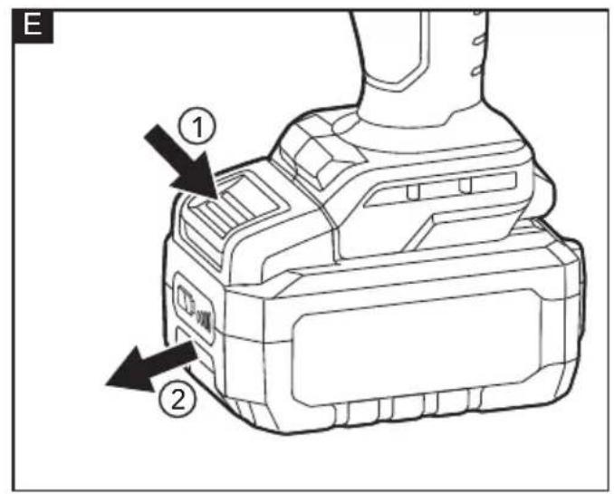
natural_image
Illustration of a hand using a screwdriver to adjust or install a mechanical component (no text or symbols visible)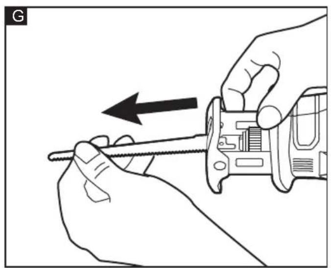
natural_image
Illustration of hands using a screwdriver to adjust a mechanical component (no text or symbols visible)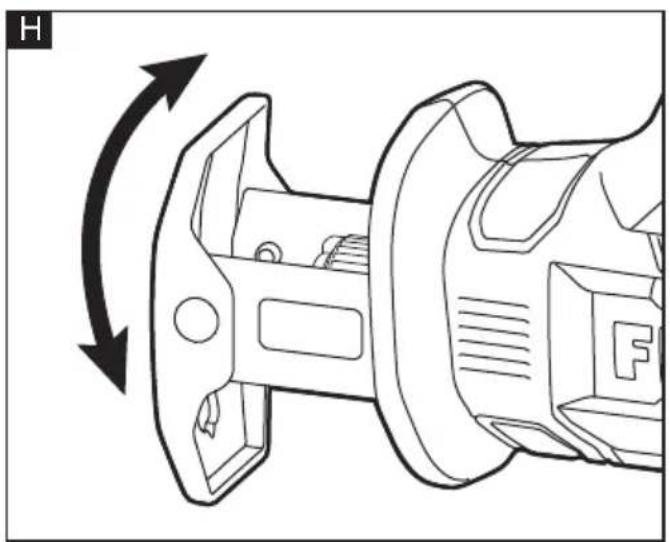
natural_image
Technical line drawing of a mechanical component with directional arrows indicating motion (no text or symbols)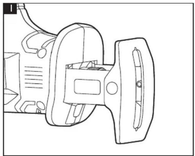
natural_image
Technical line drawing of a mechanical device with no visible text or symbols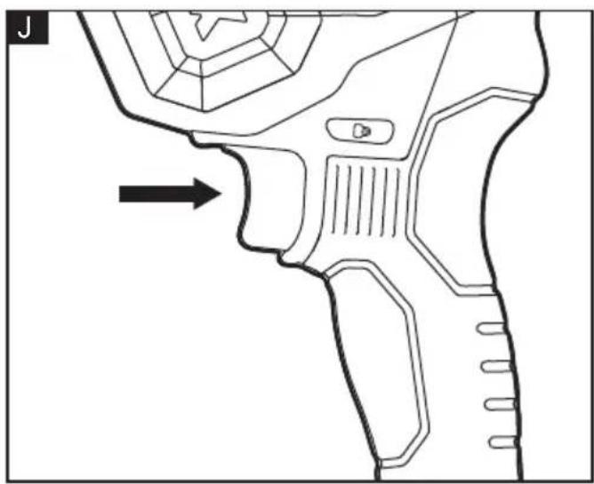
natural_image
Technical line drawing of a mechanical component with an arrow indicating direction (no text or symbols)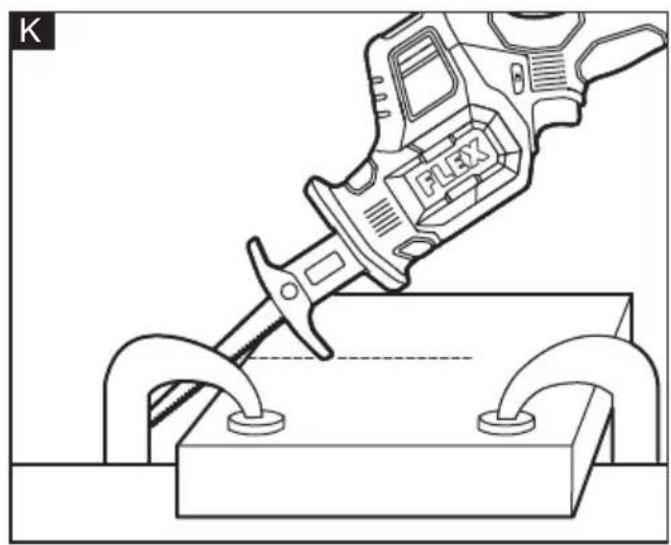
natural_image
Technical line drawing of a precision tool using a workpiece, no text or symbols present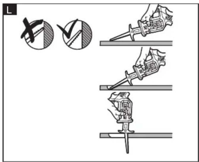
natural_image
Two circular mechanical components with clamps and a wavy central line, shown in side and top views (no text or symbols)Symbols used in this manual

WARNING!
Denotes impending danger. Non-observance of this warning may result in death or extremely severe injuries.

CAUTION!
Denotes a possibly dangerous situation. Non-observance of this warning may result in slight injury or damage to property.

NOTE
Denotes application tips and important information.
Symbols on the power tool
V
Volts
/min Rotation rate

To reduce the risk of injury, read the operating instructions!

Wear eye protection!

Wear ear protection!

Disposal information for the old machine (see page 18)!
For your safety

WARNING!
Before using the power tool, please read the follow:
– these operating instructions,
- the "General safety instructions" on the handling of power tools in the enclosed booklet (leaflet-no.: 315.915),
– the currently valid site rules and the regulations for the prevention of accidents.
This power tool is state of the art and has been constructed in accordance with the acknowledged safety regulations.
Nevertheless, when in use, the power tool may be a danger to life and limb of the user or a third party, or the power tool or other property may be damaged.
The cordless one-handed reciprocating saw may be used only
-asintended,
– in perfect working order.
Faults which impair safety must be repaired immediately.
Intended use
The cordless one-handed reciprocating saw is intended
– for commercial use in industry and trade,
– for cutting wood product, plastic and metal materials.
Safety instructions for one-handed reciprocating saw

WARNING!
Read all safety warnings, instructions, illustrations and specifications provided with this power tool. Failure to follow all instructions listed below may result in electric shock, fire and/or serious injury. Save all warnings and instructions for future reference.
- Hold the power tool by insulated gripping surfaces, when performing an operation where the cutting accessory may contact hidden wiring or its own cord. Cutting accessory contacting a "live" wire may make exposed metal parts of the power tool "live" and could give the operator an electric shock.
■ Use clamps or another practical way to secure and support the workpiece to a stable platform. Holding the workpiece by hand or against your body leaves it unstable and may lead to loss of control.
Noise and vibration
The noise and vibration values have been determined in accordance with EN 62841.
The A evaluated noise level of the power tool is typically:
RS 16 12-EC:
– Sound pressure level L_pA : 82 dB(A)
- Sound power level L_WA : 90 dB(A)
- Uncertainty: K = 5 dB
Total vibration value:
- When sawing wood:
- Emission value a_h : 5.57 m/s
- Uncertainty: K = 1.5 m/s
RS 25 18-EC:
– Sound pressure level L_pA : 87 dB(A)
- Sound power level L_WA : 95 dB(A)
– Uncertainty: K = 5 dB
Total vibration value:
- When sawing wood:
- Emission Value a_h : 9.3 m/s
– Uncertainty: K = 1.5 m/s ^2

CAUTION!
The indicated measurements refer to new power tools. Daily use causes the noise and vibration values to change.

NOTE
The vibration emission level given in this information sheet has been measured in accordance with a measurement method standardised in EN 62841 and may be used to compare one tool with another.
It may be used for a preliminary assessment of exposure. The specified vibration emission level represents the main applications of the tool.
However, if the tool is used for different applications, with different cutting accessories or poorly maintained, the vibration emission level may differ.
This may significantly increase the exposure level over the total working period.
To make an accurate estimation of the vibration exposure level, it is also necessary to take into account the times when the tool is switched off or running but not actually in use.
This may significantly decrease the exposure level over the total working period.
Identify additional safety measures to protect the operator from the effects of vibration such as: maintain the tool and the cutting accessories, keep the hands warm, organisation of work patterns.

CAUTION!
Wear ear defenders at a sound pressure above 85 dB(A).
Technical data
| Tool RS 16 | 12-EC RS 25 18-EC | ||
| Type one-handed reciprocating saw | |||
| Rated voltage | Vdc | 12 18 | |
| No-load speed | r.p.m | 0-3000 | |
| Stroke mm | 16 25.4 | ||
| Sawing capacity in wood | mm | 90 210 | |
| Sawing capacity in metal pipe | mm | 60 110 | |
| Weight according to"EPTA Procedure 01/2003"(without battery) | kg | 1.5 | 1.9 |
| Battery | AP 12/2.5AP 12/5.0AP 10.8/2.5AP 10.8/4.0AP 10.8/6.0 | AP 18.0/2.5AP 18.0/5.0AP 18.0/8.0AP 18/12.0 | |
| Weight of battery | kg | AP 12/2.5 0.3AP 12/5.0 0.4AP 10.8/2.5 0.3AP 10.8/4.0 0.4AP 10.8/6.0 0.4 | AP 18.0/2.5 0.4AP 18.0/5.0 0.7AP 18.0/8.0 1.1AP 18/12.0 1.6 |
| Working Temperature | -10 - 40°C | ||
| Storage Temperature | < 50°C | ||
| Charging Temperature | 4~40°C | ||
| Charger | CA 12/18, CA 12CA 10.8/18.0,CA 10.8 | CA 12/18CA 18.0-LDCA 10.8/18.0 | |
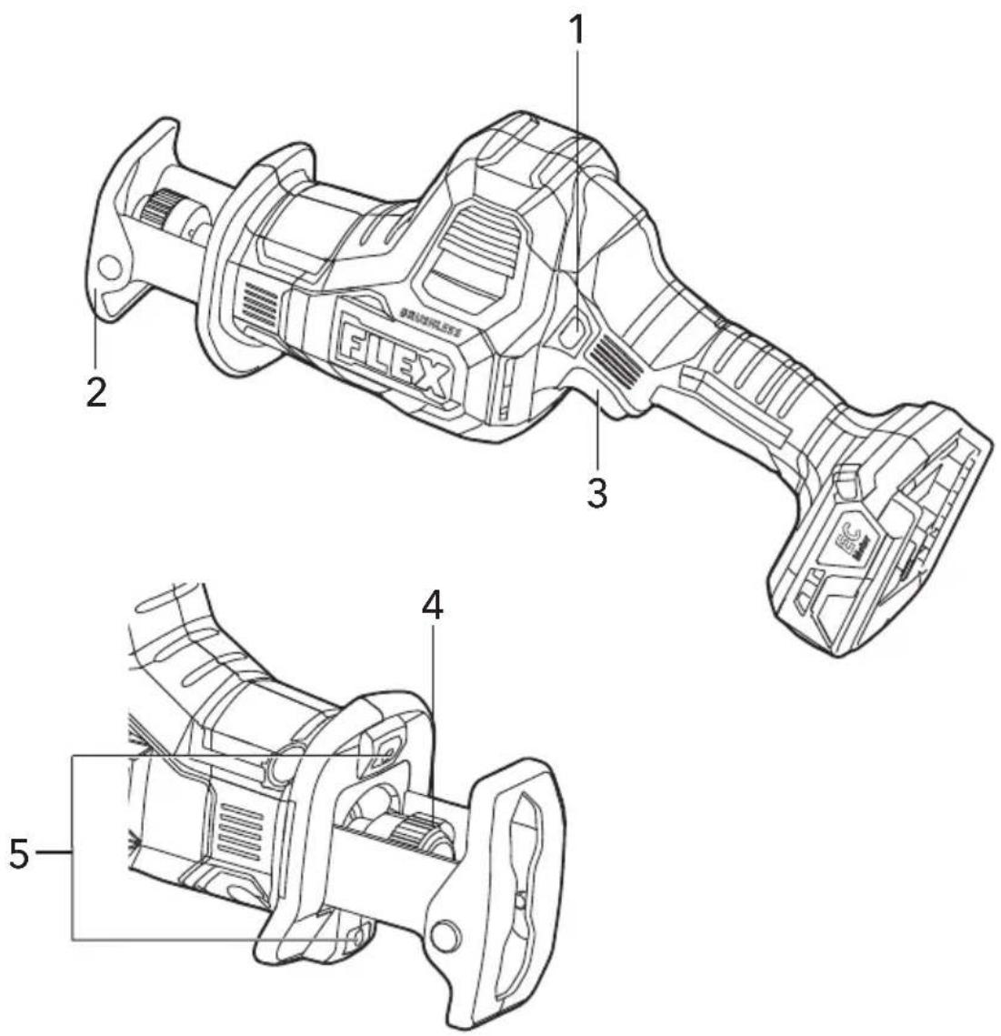
Overview (see figure A)
The numbering of the product features refers to the illustration of the machine on the graphics page.
1 Lock-off button
2 Pivoting shoe
3 Variable-speed trigger switch
4 Tool-less blade clamp sleeve
5 LED
Operating instructions

WARNING!
Remove the battery before carrying out any work on the power tool.
Before switching on the power tool
Unpack the cordless one-handed reciprocating saw and check that here are no missing or damaged parts.

NOTE
The batteries are not fully charged on delivery. Prior to initial operation, charge the batteries fully. Refer to the charger operating manual.
Inserting/replacing the battery
■ Press the charged battery into the power tool until it clicks into place (see figure D).
■ To remove, press the release button and pull out the battery (see figure E).

CAUTION!
When the device is not in use, protect the battery contacts. Loose metal parts may short circuit the contacts; explosion and fire hazard!
Install and remove saw blade

CAUTION!
Always lock the tool off and remove the battery before making any adjustments or assembling parts.
■ Place the lock-off button 1 in the locked position and then remove the battery from the tool.
- Check the status of the tool-less blade clamp sleeve 4, ensure that it is ready to accept a saw blade. If not, rotate tool-less blade clamp sleeve to open it.
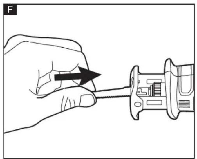
■ Hold the saw blade (sold separately) and align the shank of saw blade with the
opening of the tool-less blade clamp (see figure F).
■ Insert the saw blade into the blade clamp as far as it can go, until the tool-less blade clamp sleeve locked automatically and secures the blade in place.
■ Try to push in or pull out the blade to check whether it is locked properly.

NOTE
The blade may be installed with the teeth pointing up or down, depending on the cutting operation.
■ To remove, Rotate the tool-less blade clamp sleeve, the blade will get ejected out (see figure G).
NOTE: Occasionally the tool-less blade clamp may retract into the saw housing. If this happens, reattach the battery pack and turn the tool on by pressing the variable-speed trigger switch to move the blade clamp into a more accessible position. Remove the battery pack again.

WARNING!
When removing the saw blade, make sure the saw blade does not point at any person or animal to avoid personal injuries.

WARNING!
The saw blade may be very hot after use.
Allow the blade to cool down or wear gloves when removing a saw blade.

WARNING!
Use only a correct saw blade. Failure to heed this warning could cause loss of control and can result in possible serious injury.
Blade selection
To obtain the best performance from the saw, it is important to select the correct blade for the particular application and type of material to be cut.
Blades with fewer teeth, e.g., 7 teeth per inch (TPI), are typically used for cutting wood; blades with more teeth per inch are better for cutting metal or plastic. We recommend 6 TPI blades for wood and 14 TPI blades for metals.
Pivoting shoe adjustment (see figure H)
The shoe pivots to provide maximum control when it is aligned against the surface being cut.
■ Place the lock-off button in the locked position and remove the battery pack from the tool.
■ Firmly hold the saw and then pivot the shoe 2 to the desired angle, while taking care to avoid contact with the blade.
■ Reinstall the battery and prepare to cut.
LED (see figure I)
Your tool is equipped with LED 5, located near the blade clamp on the tool.
The LED will automatically turn on with a slight squeeze on the variable-speed trigger switch 3 before the tool starts running and will turn off approximately 10 seconds after the trigger switch is released.
The LED will rapidly flash when the tool and/or battery pack becomes overloaded or too hot. The internal sensors will turn the tool off if the tool and/or battery pack are overloaded. Rest the tool for a while or place the tool and battery pack separately under airflow to cool them.
The LED will flash more slowly to indicate that the battery is at low-battery capacity.
Recharge the battery pack.
If the LED fail to light up when you switch on the tool, or they turn off suddenly during operation, please contact customer service or an authorized service center for assistance.
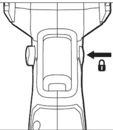
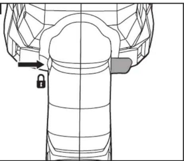
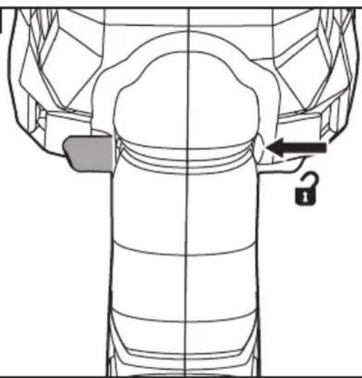
Lock-off button
Your tool is equipped with a lock-off button 1, located above the variable-speed trigger switch, to prevent the saw from being activated unintentionally.
To unlock the switch, push the lock-off button to the far right (see figure B).
To lock the switch, push the lock-off button to the far left (see figure C).
For RS 25 18-EC, the operation is just the opposite.
Switching on the power tool (see figure J)
■ To switch the power tool on:
Press the trigger switch.
The variable-speed trigger switch 3 delivers higher speed with increased trigger pressure and lower speed with decreased trigger pressure.
■ To switch the power tool off:
Release the trigger switch.
General cutting

WARNING!
Do not allow familiarity with the saw to make you careless. One careless fraction of a second is enough to inflict serious injury.

WARNING!
Never use the wood-cutting blade for cutting metals. Failure to do so could result in serious personal injury.
■ Make sure that the workpiece is firmly clamped in place to keep it from slipping or moving while cutting.
■ Install the appropriate type and size of blade for the workpiece material and size.
■ Check for clearance behind the workpiece so that the blade will not contact another surface (see figure K).
■ Mark the line of cut clearly. If cutting metal, apply cutting oil to the line.
■ Attach the battery pack to the saw.
■ Hold the saw firmly. Make sure to keep your hands on the insulated gripping areas only.
■ Depress the lock-off button to the unlocked position and squeeze the variable-speed trigger switch to start the saw and bring it to the maximum desired cutting speed before applying the blade to the workpiece.
■ Place the shoe firmly on the workpiece while cutting. Use only enough steady pressure on the blade to keep the saw cutting. Do not force the tool.
■ Reduce the pressure as the blade comes to the end of the cut.
- Allow the saw to come to a complete stop before removing the blade from the workpiece.
NOTE: Cutting speeds should vary with the workpiece. Hard materials, such as metals, require lower speeds; use higher speeds for softer materials.
When sawing fiberglass, plaster, wallboard, or spackling compound, clean the motor vents frequently with a vacuum or with compressed air. These materials are highly abrasive and may accelerate the wear on motor bearings.
Plunge cutting
Your reciprocating saw is ideal for plunge cutting directly into surfaces that cannot be cut from an edge, such as in walls or floors. Plunge cutting may be done in two ways, depending on how the blade is inserted.
■ Hold the tool firmly, resting the edge of the pivoting shoe on the workpiece.
■ With the blade just above the workpiece, place the lock-off button in the unlocked position and squeeze the variable-speed trigger switch to start the tool. Allow it to come to the desired speed. Then, using the edge of the shoe as a pivot, lower the blade into the workpiece(see figure L).
■ As the blade starts cutting, raise the handle of the tool slowly, until the shoe rests firmly and flat on the workpiece.
■ After the blade has penetrated through the workpiece, continue sawing along the marked cutting line.
Metal cutting
Never use the wood-cutting blade for cutting metals. Failure to do so could result in serious personal injury.
The saw can be used to cut metals, such as sheet steel, pipe, steel rods, aluminum, brass, and copper. Be careful not to twist or bend the saw blade. Do not force the tool.
The use of cutting oil is recommended when cutting soft metals and steel. Cutting oil will keep the blade cool, increase the cutting efficiency, and prolong blade life.
To avoid possible serious injury:
■ Never use gasoline as cutting lubricant because normal sparking could ignite the fumes.
- Securely clamp the workpiece in position and make the cut close to the clamping point to minimize vibration.
■ When cutting conduit pipe or angle iron, clamp the work in a vise, if possible, and cut close to the vise.
■ To cut thin sheet material, "sandwich" the material between pieces of hardboard or plywood and clamp the layers together to reduce vibration and tearing of the material.
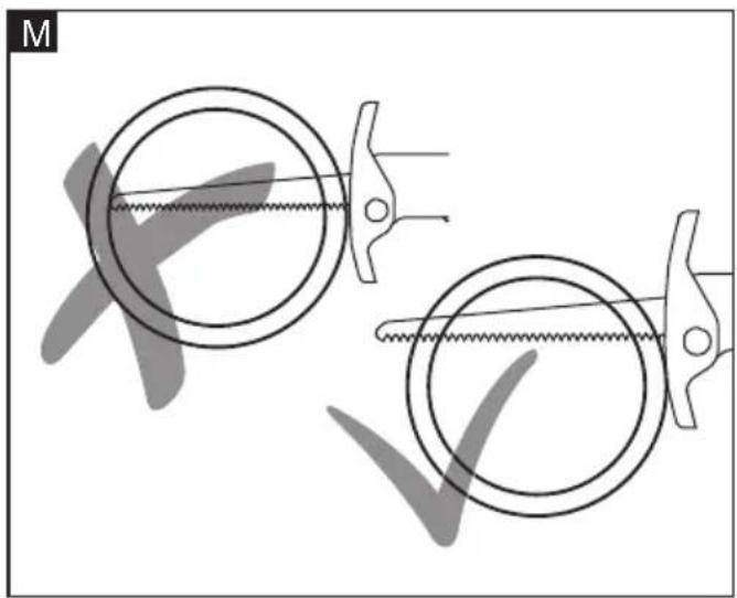
NOTE: When cutting pipes be sure the blade always extends beyond the workpiece throughout the stroke. Blades may shatter if the front on the blade hits the work
(see figure M).
Maintenance and care

WARNING!
Remove the battery before carrying out any work on the power tool.
Cleaning
■ Clean the power tool and grille in front of the vent slots regularly. Frequency of cleaning is dependent on the material and duration of use.
■ Regularly blow out the housing interior and motor with dry compressed air.
Spare parts and accessories
For other accessories, in particular tools and polishing aids, see the manufacturer's catalogues.
Exploded drawings and spare-part lists can be found on our homepage:
www.flex-tools.com
Disposal information

WARNING!
Render redundant power tools unusable:
- mains operated power tool by removing the power cord,
- battery operated power tool by removing the battery.

EU countries only Do not throw electric power tools into the household waste!
In accordance with the European Directive 2012/19/EU on Waste Electrical and Electronic Equipment and transposition into national law used electric power tools must be collected separately and recycled in an environmentally friendly manner.

Raw material recovery instead of waste disposal.
Device, accessories and packaging should be recycled in an environmentally friendly manner. Plastic parts are identified for recycling according to material type.

WARNING!
Do not throw batteries into the household waste, fire or water. Do not open used batteries.
EU countries only:
In accordance with Directive 2006/66/EC defective or used batteries must be recycled.
NOTE
Please ask your dealer about disposal options!
CE-Declaration of conformity
We declare on our sole responsibility that the product described in "Technical specifications" conforms to the following standards or normative documents: EN 62841 in accordance with the regulations of the directives 2014/30/EU, 2006/42/EC, 2011/65/EU. Responsible for technical documents: FLEX-Elektrowerkzeuge GmbH, R & D Bahnhofstrasse 15, D-71711 Steinheim/Murr

Peter Lameli Klaus Peter Weinper Technical Head Head of Quality Department
UK CA Declaration of Conformity
We as the manufacturer:
FLEX Elektrowerkzeuge GmbH, Business address: Bahnhofstr. 15, 71711 Steinheim, Germany
declare under our sole responsibility, that the product(s) described under „Technical specifications“ fulfills all the relevant provisions of The Supply of Machinery (Safety) Regulations S.I. 2008/1597 and also fulfills all the relevant provisions of the following UK Regulations: Electromagnetic Compatibility Regulations S.I. 2016/1091, The Restriction of the Use of Certain Hazardous Substances in Electrical and Electronic Equipment Regulations S.I. 2012/3032 and are manufactured in accordance with the following designated Standards: BS EN 62841-1:2015, BS EN 62841-2-11:2016/A1:2020
Place of declaration: Steinheim, Germany. Responsible person: Peter Lameli, Technical Director - FLEX-Elektrowerkzeuge GmbH
Contact details for Great Britain: FLEX Power Tools Limited, Unit 8 Anglo Office Park, Lincoln Road, HP 12, 3RH Buckinghamshire, United Kingdom.

Peter Lameli Klaus Peter Weinper Technical Head Head of Quality Department
30.11.2023
Exemption from liability
The manufacturer and his representative are not liable for any damage and lost profit due to interruption in business caused by the product or by an unusable product. The manufacturer and his representative are not liable for any damage which was caused by improper use of the product or by use of the product with products from other manufacturers.
Peter Lameli Klaus Peter Weinper Technical Head Head of Quality Department
- Negotovost: K = 5 dB(A)
- Negotovost: K = 5 dB(A)
Peter Lameli Klaus Peter Weinper Technical Head Head of Quality
Department (QD)
Peter Lameli Klaus Peter Weinper Technical Head Head of Quality Department
Peter Lameli Klaus Peter Weinper Technical Head Head of Quality
Department (QD)
Peter Lameli Klaus Peter Weinper Technical Head Head of Quality
Department (QD)
Peter Lameli Klaus Peter Weinper Technical Head Head of Quality Department


- Symbols used in this manual
- WARNING!
- CAUTION!
- NOTE
- Symbols on the power tool
- For your safety
- Intended use
- Safety instructions for one-handed reciprocating saw
- Noise and vibration
- RS 25 18-EC:
- Overview (see figure A)
- Operating instructions
- Before switching on the power tool
- Inserting/replacing the battery
- Install and remove saw blade
- Blade selection
- Pivoting shoe adjustment (see figure H)
- LED (see figure I)
- Lock-off button
- Switching on the power tool (see figure J)
- General cutting
- Plunge cutting
- Metal cutting
- Maintenance and care
- Cleaning
- Spare parts and accessories
- Disposal information
- Raw material recovery instead of waste disposal.
- CE-Declaration of conformity
- UK CA Declaration of Conformity
- Exemption from liability
Brand : Flex
Model : RS 16 12-EC
Category : Saw