
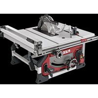
CSM 4060 - Saw Flex - Free user manual and instructions
Find the device manual for free CSM 4060 Flex in PDF.


| Product type | Saw |
| Brand | Flex |
| Model | CSM 4060 |
| Dimensions (L x W x H) | 600 x 300 x 400 mm |
| Weight | 10 kg |
| Power supply | 230 V ~ 50 Hz |
| Power consumption | 2000 W |
| Blade type | Diamond disc 400 mm |
| Maximum cutting depth | 150 mm |
| No-load speed | 2800 rpm |
| Main functions | Cutting concrete, stone, metal, wood |
| Maintenance and cleaning | Regularly clean the ventilation openings; replace worn carbon brushes |
| Safety | Blade brake, safety switch, anti-restart protection |
| Spare parts and repairability | Available at authorized dealers; repairability index: 7.5/10 |
| General information | Professional use; 2-year warranty |
Frequently Asked Questions - CSM 4060 Flex
User questions about CSM 4060 Flex
0 question about this device. Answer the ones you know or ask your own.
Ask a new question about this device
Download the instructions for your Saw in PDF format for free! Find your manual CSM 4060 - Flex and take your electronic device back in hand. On this page are published all the documents necessary for the use of your device. CSM 4060 by Flex.
USER MANUAL CSM 4060 Flex
natural_image
Illustration of a cut-out saw cutting machine with visible blades and mounting bracket (no text or symbols)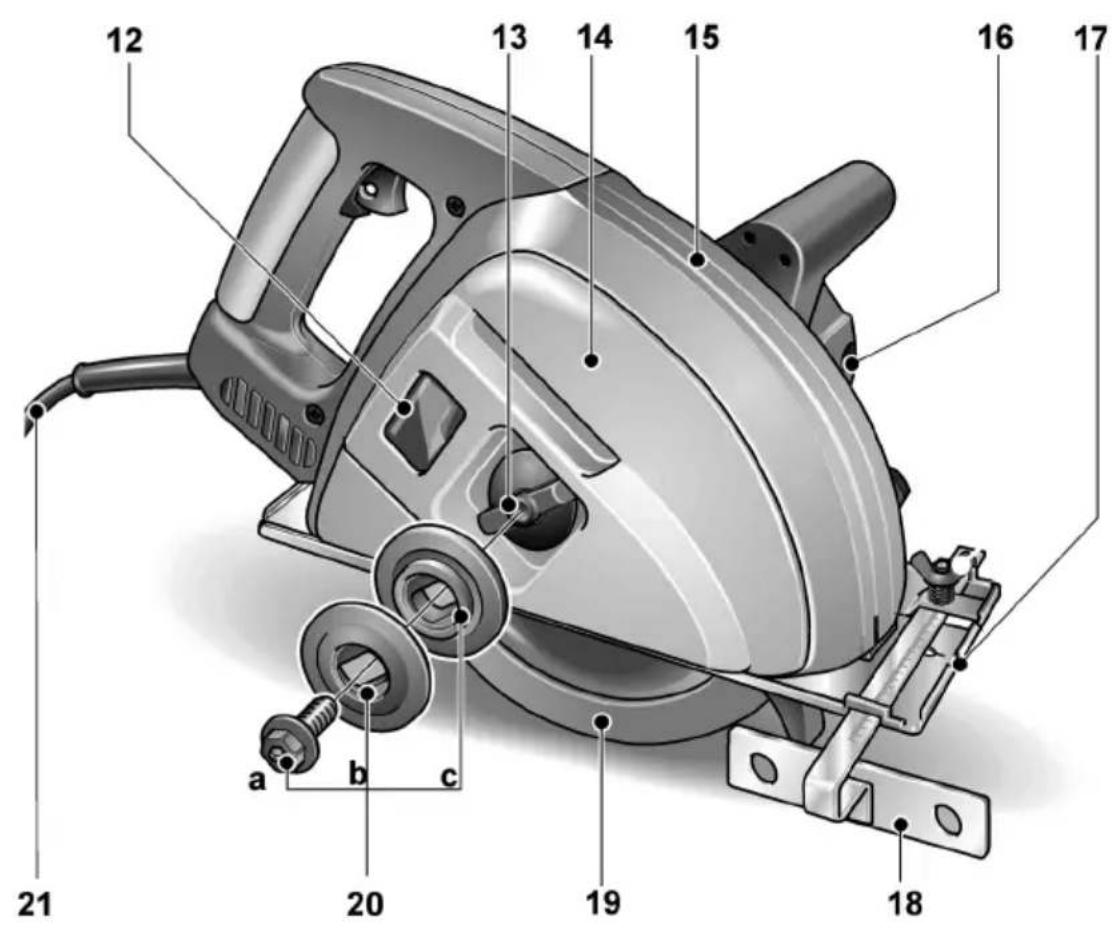
Inhalt
Inhalt 5
Auf einen Blick 5
Technische Daten 6
natural_image
Close-up of hands operating a mechanical device with a tool, no visible text or symbolsnatural_image
Cross-sectional diagram of a mechanical power saw with gear and motor components (no text or labels)natural_image
Mechanical assembly diagram showing gear and wheel components with warning symbol (no text or labels)natural_image
Illustration of a power tool cutting down a flatboard, showing mechanical components and a numbered label (3) — no text or symbols present.Manager Research & Development (R & D)
Klaus Peter WeinperEckhard F
Head of Quality
Department (QD)
29.05.2015
Contents
Contents 15
Overview 15
Technical specifications 16
Safe operating practices ..... 16
Noise and Vibration 18
Operating instructions ..... 19
Maintenance and care 21
Disposal information 22
C ∈-Declaration of Conformity ..... 23
Exemption from liability 23
Symbols used in this manual
Danger!
Denotes impending danger. Non-observance of this warning may result in death or extremely severe injuries.
Caution!
Denotes a possibly dangerous situation. Non-observance of this warning may result in slight injury or damage to property.
i Note
Denotes application tips and important information.
Symbols on the power tool

Before switching on the power tool, read the operating manual!
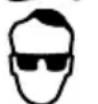
Wear goggles!

Disposal information for the old appliance (see Page 25)!
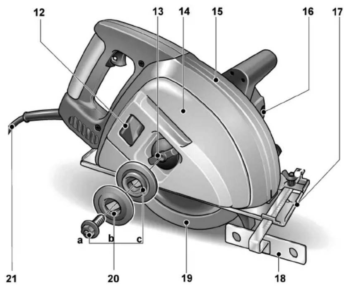
Overview
1 Handle
2 Overload protection reset button
3 Starting lockout
4 Safety switch
5 Rating plate (on underside of motor)
6 Hand grip
7 Allen screw for attachment of sawdust guard
8 Wing screw for attachment of parallel stop
9 Spindle lock for locking the spindle when changing the tool
10 Clamping lever for adjusting the cutting depth
11 Base plate
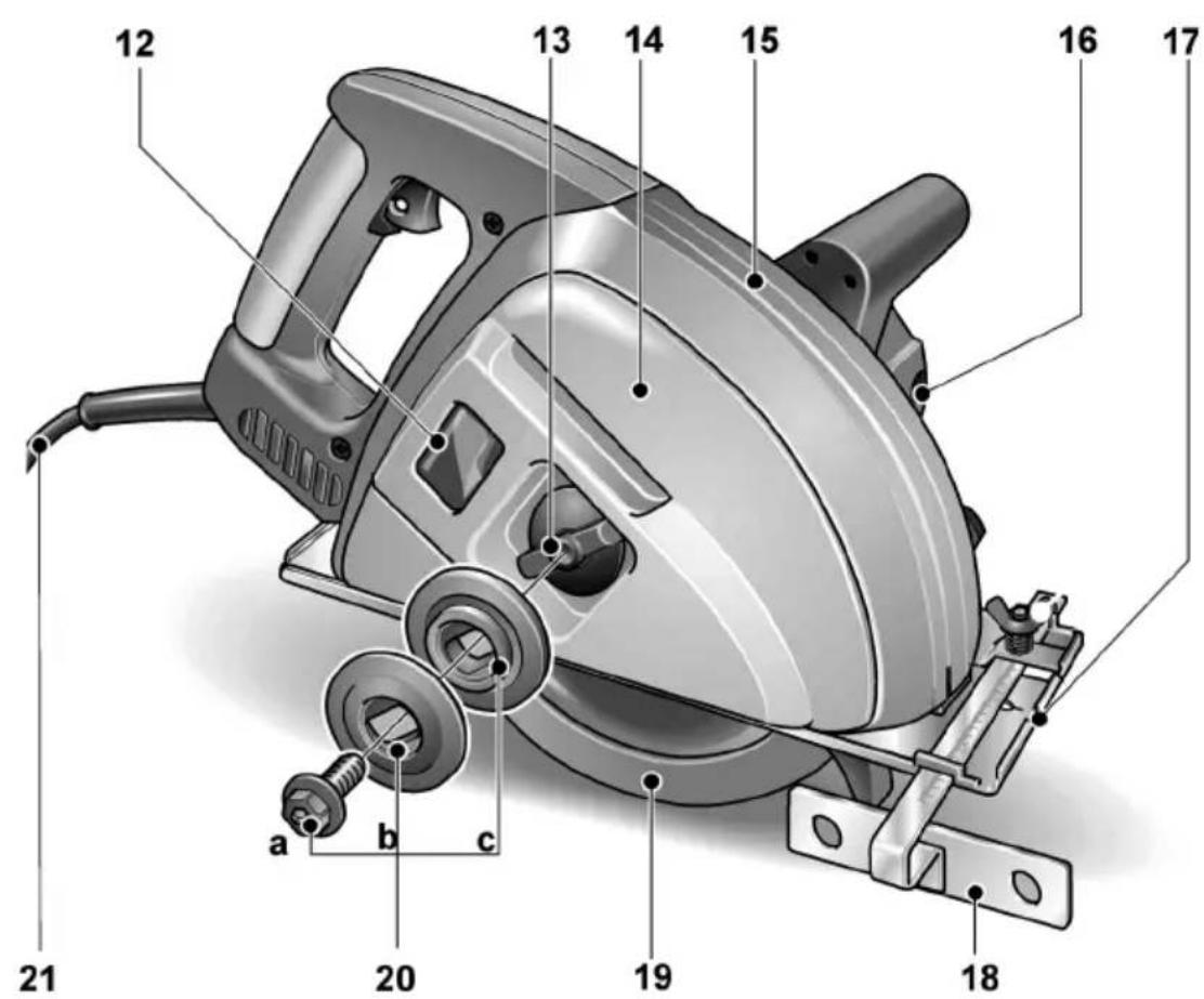
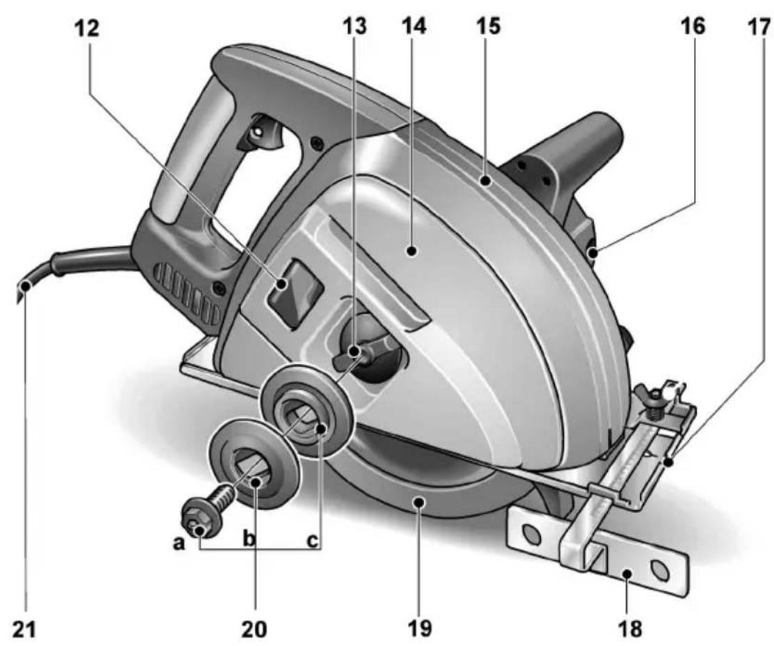
12 Window
13 Wing screw for attaching the sawdust guard and sawdust guard cover
14 Sawdust guard cover
15 Sawdust guard for catching the sawdust
16 Cover screws for carbon brushes
17 Sighting groove for guiding the power tool along a scored line
18 Parallel stop
19 Pendulum guard
20 Saw blade attachment a Locking screw b Front clamping flange c Rear clamping flange
21 Power cord with plug
Technical specifications
| Portable circular saw for metals C | CSM 4060 | |
| Saw blade diameter mm | 185 | |
| Shaft thread mm 20 | ||
| Cutting depth (max.)– Solid material– Round material– Profiles | mm | 62063 |
| No-load speed r.p.m. 3800 | ||
| Nominal voltage V/Hz 230/50 | ||
| Power input W 1400 | ||
| Power output W 620 | ||
| Weight | kg | 5.6 |
| Safety class | ☐ | |
Safe operating practices

Danger!
Before using the portable circular saw, read and follow:
– these operating instructions,
- the "Information on handling power tools" in the enclosed booklet (leaflet no. 315.915),
– the currently valid site rules and the regulations for the prevention of accidents.
This portable circular saw is state of the art and has been constructed in accordance with the acknowledged safety regulations. Nevertheless, when in use, the power tool may be a danger to life and limb of the user or a third party, or the power tool or other property may be damaged. The portable circular saw may be operated only if it is
– used as intended,
– in perfect working order.
Immediately repair any faults which impair safety.
Intended use
This portable circular saw
– is designed for industrial applications,
– is designed for cutting along and across all securely positioned metals, except stainless steel and hardened steel, with a straight cutting movement,
– is not designed for cutting wood,
– is designed for use with circular saw blades and accessories which are indicated in this manual or recommended by the manufacturer.
Not permitted are abrasive wheels.
Safe operating practices

Danger!
- Keep children away from the power tool.
- If the power cord is damaged while the power tool is being used, do not touch the power cord. Immediately pull out the mains plug. Never use a power tool which has a defective power cord.
– Before carrying out any work on the power tool, always pull out the mains plug.
– Lay the power cord to the rear away from the power tool and keep it away from the rotating saw blade.
– Never use this power tool for wet cutting. - When using the power tool, wear ear protection and goggles!
– Guide the power tool away from your body. - Never work overhead.
- Ensure that the upper and lower sides of the cutting path are free from obstructions.
- Keep hand away from cutting area and the blade. Keep your second hand on auxiliary handle, or motor housing. If both hands are holding the saw, they cannot be cut by the blade.
- Do not reach underneath the workpiece. The guard cannot protect you from the blade below the workpiece.
-
Adjust the cutting depth to the thickness of the workpiece.
Less than a full tooth of the blade teeth should be visible below the workpiece. -
Never hold piece being cut in your hands or across your leg. Secure the workpiece to a stable platform.
It is important to support the work properly to minimize body exposure, blade binding, or loss of control. - Hold power tool by insulated gripping surfaces when performing an operation where the cutting tool may contact hidden wiring or its own cord.
Contact with a "live" wire will also make exposed metal parts of the power tool "live" and shock the operator. - When ripping always use a rip fence or straight edge guide.
This improves the accuracy of cut and reduces the chance of blade binding. - Always use blades with correct size and shape (diamond versus round) of arbour holes.
Blades that do not match the mounting hardware of the saw will run eccentrically, causing loss of control. - Never use damaged or incorrect blade washers or bolt.
The blade washers and bolt were specially designed for your saw, for optimum performance and safety of operation. - Before using the power tool and saw blade, check them for damage, imbalances and vibrations. Conduct a test run!
- Use only saw blades which have a permitted speed at least as high as the nominal speed of the power tool.
- Switch on the portable circular saw before guiding it towards the workpiece.
- Do not load the power tool to such an extent that it stops.
- When using the power tool, hazardous substances may be released.
Take suitable precautions (e.g. wear a dust-proof mask).
– Never saw materials which contain asbestos. - Never saw light-weight metals which have a magnesium content greater than 80% . Risk of fire!
- If power tools are used outdoors or are exposed to extreme metal dust, connect via a residual-current-operated circuit-breaker (tripping current max. 30 mA).
- Mark the power tool with adhesive labels only. Do not drill any holes into the housing.
Causes and operator prevention of kickback:
- Kickback is a sudden reaction to a pinched, bound or misaligned saw blade, causing an uncontrolled saw to lift up and out of the workpiece toward the operator;
- When the blade is pinched or bound tightly by the kerf closing down, the blade stalls and the motor reaction drives the unit rapidly back toward the operator;
- If the blade becomes twisted or misaligned in the cut, the teeth at the back edge of the blade can dig into the top surface of the wood causing the blade to climb out of the kerf and jumb back toward the operator.
Kickback is result of saw misuse and/or incorrect operating procedures or conditions and can be avoided by taking proper precautions as given below.
- Maintain a firm grip with both hands on the saw and position your arms to resist kickback forces. Position your body to either side of the blade, but not in line with the blade.
Kickback could cause the saw to jump backwards, but kickback forces can be controlled by the operator, if proper precautions are taken.
- When blade is binding, or when interrupting a cut for any reason, release the trigger and hold the saw motionless in the material until the blade comes to a complete stop. Never attempt to remove the saw from the work or pull the saw backward while the blade is in motion or kickback may occur.
Investigate and take corrective actions to eliminate the cause of blade binding.
- When restarting a saw in the workpiece, centre the saw blade in the kerf and check that saw teeth are not engaged into the material.
If saw blade is binding, it may walk up or kickback from the workpiece as the saw is restarted. - Support large panels to minimise the risk of blade pinching and kickback. Large panels tend to sag under their own weight. Supports must be placed under the panel on both sides, near the line of cut and near the edge of the panel.
- Do not use dull or damaged blades. Unsharpened or improperly set blades produces narrow kerf causing expressive friction, blade binding and kickback.
- Blade depth and bevel adjusting locking levers must be tight and secure before making cut.
If blade adjustment shifts while cutting, it may cause binding and kickback. - Use extra caution when making a "plunge cut" into existing walls or other blind areas.
The protruding blade may cut objects that can cause kickback.
Guard
- Check lower guard for proper closing before each use. Do not operate the saw if lower guard does not move freely and close instantly. Never clamp or tie the lower guard into the open position. If saw is accidentally dropped, lower guard may be bent. Raise the lower guard with the retracting handle and make sure it moves freely and does not touch the blade or any other part, in all angles and depths of cut.
- Check the operation of the lower guard spring. If the guard and the spring are not operating properly, they must be serviced before use.
Lower guard may operate sluggishly due to damaged parts, gummy deposits, or a build-up of debris.
– Lower guard should be retracted manually only for special cuts such as “plunge cuts” and “compound cuts”.
Raise lower guard by retracting handle and as soon as blade enters the material, the lower guard must be released. For all other sawing, the lower guard should operate automatically.
- Always observe that the lower guard is covering the blade before placing saw down on bench or floor.
An unprotected, coasting blade will cause the saw to walk backwards, cutting whatever is in path. Be aware of the time it takes for the blade to stop after switch is released.

Damage to property!
The mains voltage and the voltage specifications on the rating plate (5) must correspond.
Noise and Vibration
The noise and vibration values have been determined in accordance with EN 60745. The a evaluated noise level of the power tool is typically:
– Sound pressure level: 98 dB(A);
– Sound power level: 109 dB(A);
- Uncertainty: K = 3 dB.
Total vibration value (when sawing metal):
- Emissions value: a _h=2,3m^2s Uncertainty: K=1.5 m/s
– Uncertainty: K = 1.5 m/s

Attention
The indicated measurements refer to new power tools. Daily use causes the noise and vibration values to change.

Notes
The vibration emission level given in this information sheet has been measured in accordance with a standardised test given in EN 60745 and may be used to compare one tool with another. It may be used for a preliminary assessment of exposure. The declared vibration emission level represents the main applications of the tool.
However if the tool is used for different applications, with different accessories or poorly maintained, the vibration emission may differ.
This may significantly increase the exposure level over the total working period.
For a precise estimation of the vibration load the times should also be considered during which the power tool is switched off or even running, but not actually in use. This may significantly increase the exposure level over the total working period
Identify additional safety measures to protect the operator from the effects of vibration such as: maintain the tool and the accessories, keep the hands warm, organisation of work patterns.

Caution
Wear ear protection at a sound pressure above 85 dB(A).
Operating instructions

Danger!
Before carrying out any work on the power tool, always pull out the mains plug.
Before switching on the power tool
Unpack the portable circular saw and check that there are no missing or damaged parts. Compare the mains voltage with the specifications on the rating plate (5).
Attaching or changing the saw blade
■ Pull out the mains plug.

■ Loosen the Allen screws (7) and remove the sawdust guard (15).

natural_image
Close-up of hands operating a mechanical device with a tool, no visible text or symbols■ Press and hold down the spindle lock (9). Loosen the locking screw (20 a) in an anticlockwise direction with an Allen key.
natural_image
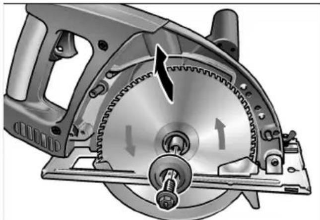
Technical illustration of a mechanical power saw with gear and mounting base (no text or symbols)■ Unscrew the locking screw (20 a) and remove the front clamping flange (20 b). Remove the saw blade.

Danger!
- Observe the installation location of the rear clamping flange (20 c) and front clamping flange (20 b).
- The cutting direction of the teeth (direction of arrow on the saw blade) and direction-of-rotation arrow on the housing must agree.

natural_image
Mechanical assembly diagram showing gear meshing and a warning symbol (no text or labels)■ Insert the saw blade in the correct position. Attach the front clamping flange (20 b) with the flange on the outside and manually tighten the locking screw (20 a) in a clockwise direction.
■ Press and hold down the spindle lock (9). Tighten the locking screw (20 a) in a clockwise direction with an Allen key.
■ Attach the sawdust guard (15) and secure with the Allen screws (7).
Switch on and off

Note
For reasons of safety the safety switch (4) is not locked and must be held down during sawing.
Switching on:
■ Press and hold down the starting lockout (3).
■ Press and hold down the safety switch (4).
■ Release the starting lockout (3).
Switching off:
■ Release the safety switch (4).
Setting the cutting depth

Note
For optimum cutting results the saw blade may project out of the workpiece by max. 3 mm.
■ Pull out the mains plug.

■ Loosen the clamping lever (10).
■ Set the required cutting depth: Lift the saw off the base plate (11) = lower cutting depth.

natural_image
Illustration of a power tool being installed on a cutting board, showing mechanical components and wiring (no text or symbols)■ Tighten the clamping lever (10).
Operation

Caution!
- After the power tool has been switched off, the saw blade continues running briefly.
- When the running saw blade touches the workpiece, the power tool may recoil.
Sawing

Note!
Excessive feed reduces the performance of the power tool, impairs the cutting quality and reduces the service life of the saw blade.
■ Take hold of the handle (1) with your right hand and the additional hand grip (6) with your left hand.
■ Switch on the power tool and wait until the saw blade has reached the maximum speed.
■ Slowly bring the power tool towards the material.
■ Guide the power tool through the material at a uniform feed.
Parallel stop
Facilitates cuts parallel to the edge of the workpiece.
■ Loosen the wing screw (8).
■ Set the parallel stop (18) to the required width.
■ Tighten the wing screw (8).
Overload protection
If there is an extreme overload, the overload protection system protects the motor from damage by automatically switching off the power tool.
■ Release the safety switch (4).
■ Pull out the mains plug.
■ Leave the appliance to cool down for at least 3 minutes.
■ Press the overload protection reset button (2).
The power tool is ready to use again.
Maintenance and care

Danger!
Before carrying out any work on the power tool, always pull out the mains plug.
Cleaning

Danger!
Impairment of the protective insulation! If metals are sawn over a prolonged period, conductive dust may become deposited inside the housing.
Operate the power tool via a residual-current-operated circuit-breaker (tripping current 30 mA).
■ Regularly clean the power tool and ventilation slots.
■ Regularly blow out the housing interior and motor with dry compressed air.
Pendulum guard

Danger!
The pendulum guard (19) must always move freely and close independently. Always keep the pendulum guard and return spring clean.
■ Remove dust and chips with a paint brush or dry compressed air.
Sawdust guard
The discharge of sawdust and collection in the sawdust guard (15) can be observed via the window (12).
Empty the sawdust guard when it is approx. half full.

Caution
Metal sawdust is very hot. Do not touch with bare hand.
Repairs
Repairs may be carried out only by a customer service workshop authorised by the manufacturer.
Accessories
Accessories Order no.
Saw blade 312.304
Parallel stop 312.312
■ Loosen the wing screw (13) and remove the sawdust guard cover (14).
■ Remove sawdust and clean the interior with a paint brush.
■ Attach the sawdust guard cover (14) and secure with the wing screw (13).
or
■ loosen the Allen screws (7) and remove the sawdust guard (15).
■ Empty the sawdust guard and re-attach.
Carbon brushes
Regularly check the carbon brushes.
They must move freely in their holder.
They must be changed when their residual length is below 6 mm.
Note!
Use only original parts supplied by the manufacturer for replacement purposes. If non-original parts are used, the guarantee obligations of the manufacturer will be deemed null and void.
■ Unscrew the cover screws (16) on the carbon brushes with a screwdriver.
■ Pull out the carbon brushes, clean and check them. Replace worn carbon brushes.
■ Insert the carbon brushes. Screw in the cover screws (16).
Disposal information
Danger!
Render redundant power tools unusable by removing the power cord.
Only for EU countries
Do not dispose of electric tools together with household waste material!
In observance of European Directive 2012/19/EC on waste electrical and electronic equipment and its implementation in accordance with national law, electric tools that have reached the end of their life must be collected separately and returned to an environmentally compatible recycling facility.
Note!
Please ask your dealer about disposal options for redundant power tools.
CE Declaration of Conformity
We declare under our sole responsibility that the product described under “Technical specifications” conforms to the following standards or normative documents:
EN 60745 in accordance with the regulations of the directives
2004/108/EC (until 19.04.2016),
2014/30/EU (from 20.04.2016),
2006/42/EC, 2011/65/EC.
Responsible for technical documents:
Manager Research & Development (R & D)
Klaus Peter WeinperEckhard F
Head of Quality
Department (QD)
Exemption from liability
The manufacturer and his representative are not liable for any damage and lost profit due to interruption in business caused by the product or by an unusable product. The manufacturer and his representative are not liable for any damage which was caused by improper use of the product or by use of the product with products from other manufacturers.


Sommaire
Sommaire 25
Vue d'ensemble 25
3 Cran anti-enclenchement
natural_image
Illustration of hands operating a mechanical device with a tool, no visible text or symbolsnatural_image
Cross-sectional diagram of a mechanical power saw with gear and motor components (no text or labels)natural_image
Mechanical assembly diagram showing gear and wheel components with warning symbol (no text or labels)natural_image
Illustration of a power tool cutting into a flatboard (no text or symbols visible)Protection anti-surcharge
Manager Research & Development (R & D)
Klaus Peter WeinperEckhard F
Head of Quality Department (QD)
29.05.2015

Indice
Indice 35
Guida rapida 35
Dati tecnici 36
natural_image
Close-up of hands operating a mechanical device with a tool, no visible text or symbolsnatural_image
Cross-sectional diagram of a mechanical power saw with gear and motor components (no text or labels)natural_image
Mechanical assembly diagram showing gear and wheel components with warning symbol (no text or labels)natural_image
Illustration of a power tool cutting down an electronic board (no text or symbols visible)Manager Research & Development (R & D)
Klaus Peter WeinperEckhard F Head of Quality Department (QD)
29.05.2015
Contenido
Contenido 45
De un vistazo 45
Datos técnicos 46
natural_image
Close-up of hands operating a mechanical device with a tool, no visible text or symbolsnatural_image
Cross-sectional diagram of a mechanical power saw with gear and motor components (no text or labels)natural_image
Mechanical assembly diagram showing gear and wheel components with directional arrows and warning symbol (no text labels)natural_image
Illustration of a power tool cutting into a flatboard (no text or symbols visible)■ Ajustar la palanca de ajuste (10).
Manejo

¡Cuidado!
Manager Research &
Development (R & D)

Inhoud
Inhoud 57
natural_image
Close-up of hands operating a mechanical device with a tool, no visible text or symbolsnatural_image
Cross-sectional diagram of a mechanical power saw with gear and motor components (no text or labels)natural_image
Mechanical assembly diagram showing gear and wheel components with warning symbol (no text or labels)natural_image
Illustration of a hairdryer cutting into a flatboard, showing mechanical components and tool path (no text or symbols)■ Draai de spanhendel (10) vast.
Bediening

Voorzichtig!
Manager Research & Development (R & D)
Klaus Peter WeinperEckhard F
Head of Quality
Department (QD)
29.05.2015
Innehåll
Innehåll 67
Översikt 67
Tekniska data 68
För din säkerhet 68
natural_image
Close-up of hands operating a mechanical device with a tool, no visible text or symbolsnatural_image
Cross-sectional diagram of a mechanical power saw with gear and motor components (no text or labels)natural_image
Mechanical assembly diagram showing gear and wheel components with directional arrows (no text or labels)natural_image
Illustration of a power tool cutting down a flatboard (no text or symbols visible)Manager Research & Development (R & D)

Klaus Peter WeinperEckhard F
Head of Quality
Department (QD)
29.05.2015


- Inhalt
- Contents
- Symbols used in this manual
- Danger!
- Caution!
- i Note
- Symbols on the power tool
- Overview
- Safe operating practices
- Intended use
- Causes and operator prevention of kickback:
- Guard
- Damage to property!
- Noise and Vibration
- Attention
- Notes
- Caution
- Operating instructions
- Before switching on the power tool
- Attaching or changing the saw blade
- Switch on and off
- Note
- Switching on:
- Switching off:
- Setting the cutting depth
- Operation
- Sawing
- Note!
- Parallel stop
- Overload protection
- Maintenance and care
- Cleaning
- Pendulum guard
- Sawdust guard
- Repairs
- Accessories
- Carbon brushes
- Disposal information
- CE Declaration of Conformity
- Exemption from liability
- Sommaire
- Protection anti-surcharge
- Indice
- Contenido
- Manejo
- ¡Cuidado!
- Inhoud
- Bediening
- Voorzichtig!
- Innehåll
Brand : Flex
Model : CSM 4060
Category : Saw