
GLM 5027 CG Professional - Laser pointer BOSCH - Free user manual and instructions
Find the device manual for free GLM 5027 CG Professional BOSCH in PDF.
| Product type | Laser distance meter |
| Brand and model | Bosch GLM 50-27 CG Professional |
| Measuring range | 0.05 to 50 m (favorable conditions), 0.05 to 20 m (unfavorable conditions) |
| Measuring accuracy | ±1.5 mm (favorable conditions), ±3.0 mm (unfavorable conditions) |
| Smallest display unit | 0.5 mm |
| Inclination measuring range | 0° to 360° (4 x 90°) |
| Inclination measurement accuracy | ±0.2° (typical) |
| Laser class | 2 (green laser 515 nm, < 1 mW) |
| Power supply | 2 LR6 (AA) 1.5 V batteries; Lithium-ion 3.7 V 1.0 Ah rechargeable battery (optional) |
| Weight (according to EPTA 01:2014) | 0.17 kg |
| Dimensions (L × W × H) | 119 × 53 × 29 mm |
| Protection class | IP 65 (dust-tight and protected against water jets) |
| Operating temperature | -10 °C to +45 °C (in continuous mode up to +40 °C) |
| Storage temperature | -20 °C to +70 °C |
| Data transmission | Bluetooth® 4.2 Low Energy (2402-2480 MHz band, 8 mW power) |
| Measurement memory | Up to 30 values |
| Measuring functions | Length, area, volume, indirect height measurement (single and double), indirect length measurement, wall area, stake-out, continuous measurement (min/max, large digits, tape measure), electronic level, inclination |
| Display | Backlit LCD with value and function display |
| Automatic switch-off | Laser: 20 s; device without measurement: 5 min (with Bluetooth® disabled) |
| Supplied accessories | Protective pouch, wrist strap, laser target, laser viewing glasses, tripod (not included) |
| Care and cleaning | Clean with a soft, damp cloth; do not use detergents or solvents; store in the protective pouch |
| Repairability | Repair by an authorized Bosch after-sales service; spare parts available at www.bosch-pt.com |
Frequently Asked Questions - GLM 5027 CG Professional BOSCH
User questions about GLM 5027 CG Professional BOSCH
0 question about this device. Answer the ones you know or ask your own.
Ask a new question about this device
Download the instructions for your Laser pointer in PDF format for free! Find your manual GLM 5027 CG Professional - BOSCH and take your electronic device back in hand. On this page are published all the documents necessary for the use of your device. GLM 5027 CG Professional by BOSCH.
USER MANUAL GLM 5027 CG Professional BOSCH
www.bosch-pt.com/serviceaddresses
1609 92A 4ZJ| (14.10.2020) Bosch Power Tools
Transport
All instructions must be read and observed in order for the measuring tool to function safely. The safeguards integrated into the measuring tool may be compromised if the measuring tool is not used in accordance with these instructions. Never make warning
Bosch Power Tools 1 609 92A 4ZJ| (14.10.2020)
34 | English
signs on the measuring tool unrecognisable. SAVE THESE INSTRUCTIONS FOR FUTURE REFERENCE AND INCLUDE THEM WITH THE MEASURING TOOL WHEN TRANSFERRING IT TO A THIRD PARTY.
Warning! If operating or adjustment devices other than those specified here are used or other procedures are carried out, this can lead to dangerous exposure to radiation.
The measuring tool is delivered with a laser warning sign (marked in the illustration of the measuring tool on the graphics page).
If the text of the laser warning label is not in your national language, stick the provided warning label in your national language over it before operating for the first time.
Do not direct the laser beam at persons or animals and do not stare into the direct or reflected laser beam yourself. You could blind somebody, cause accidents or damage your eyes.
If laser radiation hits your eye, you must close your eyes and immediately turn your head away from the beam.
Do not make any modifications to the laser equipment.
Do not use the laser goggles (accessory) as protective goggles. The laser goggles make the laser beam easier to see; they do not protect you against laser radiation.
- Do not use the laser goggles (accessory) as sunglasses or while driving. The laser goggles do not provide full UV protection and impair your ability to see colours.
Have the measuring tool serviced only by a qualified specialist using only original replacement parts. This will ensure that the safety of the measuring tool is maintained.
Do not let children use the laser measuring tool unsupervised. They could unintentionally blind themselves or other persons.
- Do not use the measuring tool in explosive atmospheres which contain flammable liquids, gases or dust. Sparks may be produced inside the measuring tool, which can ignite dust or fumes.
Do not open the battery. There is a risk of short-circuiting.
In case of damage and improper use of the battery, vapours may be emitted. The battery can set alight or explode. Ensure the area is well ventilated and seek medical attention should you experience any adverse effects. The vapours may irritate the respiratory system.
If used incorrectly or if the battery is damaged, flammable liquid may be ejected from the battery. Contact with this liquid should be avoided. If contact accidentally occurs, rinse off with water. If the liquid comes into contact with your eyes, seek additional medical attention. Liquid ejected from the battery may cause irritation or burns.
The battery can be damaged by pointed objects such as nails or screwdrivers or by force applied externally. An internal short circuit may occur, causing the battery to burn, smoke, explode or overheat.
- When the battery is not in use, keep it away from paper clips, coins, keys, nails, screws or other small metal objects that could make a connection from one terminal to another. A short circuit between the battery terminals may cause burns or a fire.
- Only use the battery with products from the manufacturer. This is the only way in which you can protect the battery against dangerous overload.
- Only charge the batteries using chargers recommended by the manufacturer. A charger that is suitable for one type of battery may pose a fire risk when used with a different battery.

Protect the battery against heat, e.g. against continuous intense sunlight, fire, dirt, water and moisture. There is a risk of explosion and short-circuiting.
- Caution! Using the measuring tool with Bluetooth® can cause faults to occur in other devices and systems, aeroplanes and medical devices (e.g. pacemakers, hearing aids). Also, damage to people and animals in the immediate vicinity cannot be completely excluded. Do not use the measuring tool with Bluetooth® in the vicinity of medical devices, petrol stations, chemical plants, areas with a potentially explosive atmosphere and in blasting areas. Do not use the measuring tool with Bluetooth® on aeroplanes. Avoid using the product near your body for extended periods.
The Bluetooth® word mark and logos are registered trademarks owned by Bluetooth SIG, Inc. and any use of such marks by Robert Bosch Power Tools GmbH is under license.
Product Description and Specifications
Please unfold the fold-out page with the diagram of the measuring tool and leave it open while reading the instruction manual.
36 | English
Intended Use
The measuring tool is intended for measuring distances, lengths, heights, clearances and inclines, and for calculating areas and volumes.
The measuring tool is suitable for indoor and outdoor use.
The measuring results can be transferred to other devices via Bluetooth®.
Product features
The numbering of the product features shown refers to the illustration of the measuring tool on the graphic page.
(1) Bluetooth® button
(2) Function button [Func]
(3)Minus/left[-]button
(4) Display
(5) Measuring button [ ]
(6) Plus/right [+] button
(7) Basic settings [按钮
(8) On/off/back button [B]
(9) Eyelet for carrying strap
(10) Laser warning label
(11) Serial number
(12) Battery compartment cover locking mechanism
(13) Battery compartment cover
(14) 1/4" tripod thread
(15) Reception lens
(16) Laser beam output
(17) Belt clip
(18) ScrewA) for belt clipA)
(19) Laser target plate
(20) Laser viewing glasses
(21) Tripod
(22) Carrying strap
(23) Protective bag
(24) Li-ion battery pack
(25) Li-ion battery pack locking mechanism
(26) USB Type-C® cable A)B)
(27) Flap for USB Type-C® port
A) Accessories shown or described are not included with the product as standard. You can find the complete selection of accessories in our accessories range.
B) USB Type-C® and USB-C® are trademarks of USB Implementers Forum.
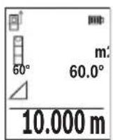
Display elements (selection)
(a) Reference level of measurement
(b) Connection status

(c) Battery indicator
(d) Measured value lines
(e) Result line
(f) Measuring function
(g) Slope angle display
(h) Status bar
(i) Measuring function display indicator
(j) Basic settings display indicator
(k) More settings display indicator
Technical data
| Digital laser measure GLM 50-27 CG GLM 50-27 C | ||
| Article number | 3601 K72 U.. 3601 K72 T.. | |
| Distance measurement | ||
| Measuring range 0.05–50 m | A) | 0.05–50 mA) |
| Measuring range (unfavourable conditions) | 0.05–20 mB) | 0.05–20 mB) |
| Measuring accuracy ±1.5 mm | A) | ±1.5 mmA) |
Bosch Power Tools 1609 92A 4ZJ|(14.10.2020)
38 | English
Digital laser measure GLM 50-27 CG GLM 50-27 C
| Measuring accuracy (unfavour-able conditions) | ±3.0 mmB) | ±3.0 mmB) |
| Smallest display unit 0.5 mm 0.5 mm | ||
| Indirect distance measurement and level | ||
| Measuring range 0°-360° (4 x 90°) 0°-360° (4 x 90°) | ||
| Grade measurement | ||
| Measuring range 0°-360° (4 x 90°) 0°-360° (4 x 90°) | ||
| Measuring accuracy (typical) ±0.2° | C)D) | ±0.2°C)D) |
| Smallest display unit 0.1° 0.1° | ||
| General | ||
| Operating temperature -10 °C to +45 °C | E) | -10 °C to +45 °CE) |
| Permitted charging temperature range | 0 °C to +60 °C | 0 °C to +60 °C |
| Storage temperature -20 °C to +70 °C | -20 °C to +70 °C | |
| Relative air humidity max. 90 % | 90 % | |
| Max. altitude 2000 m 2000 m | ||
| Pollution degree according to IEC 61010-1 | 2F) | 2F) |
| Laser class | 2 | 2 |
| Laser type | 515 nm, < 1 mW | 635 nm, < 1 mW |
| Divergence of the laser beam | < 1.5 mrad (full angle) | < 1.5 mrad (full angle) |
| Automatic switch-off after approx. | ||
| - Laser | 20 s | 20 s |
| - Measuring tool (without measurement) | 5 minG) | 5 minG) |
| Weight according to EPTA-Pro-cEDURE 01:2014 | 0.17 kg | 0.17 kg |
| Dimensions | 119 x 53 x 29 mm | 119 x 53 x 29 mm |
| Protection rating | IP 65 (protection against dust ingress and water jets) | IP 65 (protection against dust ingress and water jets) |
Digital laser measure GLM 50-27 CG GLM 50-27 C
| Batteries 2 x 1.5 V LR6 (AA) 2 x 1.5 V LR6 (AA) | ||
| Unit of measurement setting m, ft, in m, ft, in | ||
| Battery pack (accessory) Li-ion Li-ion | ||
| Type BA 3.7 V 1.0 Ah A BA 3.7 V 1.0 Ah A | ||
| Article number | 1607 A35 ON8 | 1607 A35 ON8 |
| USB charging connection Type-C® Type-C® | ||
| recommended USB Type-C® cable | 1600 A01 6A8 | 1600 A01 6A8 |
| Rated voltage 3.7 V 3.7 V | - | - |
| Capacity 1.0 Ah | 1.0 Ah | |
| Number of battery cells | 1 | 1 |
| Power supply | ||
| Output voltage | 5.0 V 5.0 V | - |
| Output current | 500 mA | 500 mA |
| Recommended power supply | 2609 120 713 (EU) | 2609 120 713 (EU) |
| 2609 120 718 (UK) | 2609 120 718 (UK) | |
| 1600 A01 3A0 (ARG) | 1600 A01 3A0 (ARG) | |
| 1600 A01 3A1 (MEX) | 1600 A01 3A1 (MEX) | |
| 1600 A01 3A2 (BRL) | 1600 A01 3A2 (BRL) | |
| Data transfer | ||
| Bluetooth® | Bluetooth® (4.2 Low Energy)H) | Bluetooth® (4.2 Low Energy)H) |
| Operating frequency band | 2402-2480 MHz | 2402-2480 MHz |
40 | English
Digital laser measure GLM 50-27 CG GLM 50-27 C
Max. transmission power 8 mW 8 mW
A) For measurements from the front edge of the measuring tool, this applies for high reflectivity of the target (e.g. a white-painted wall), weak backlighting and 25°C operating temperature. In addition, a deviation of ± 0.05mm / m must be taken into account, depending on the distance.
B) For measurements from the front edge of the measuring tool, this applies for high reflectivity of the target (e.g. a white-painted wall), strong backlighting and 25°C operating temperature. In addition, a deviation of ± 0.15mm / m must be taken into account, depending on the distance.
C) After user calibration at 0° and 90° ; An additional grade error of ± 0.01° /degree to 45° (max.) has to be taken into account. The left-hand side of the measuring tool serves as the reference level for grade measurement.
D) At an operating temperature of 25°C
E) In continuous measurement mode, the max. operating temperature is +40°C .
F) Only non-conductive deposits occur, whereby occasional temporary conductivity caused by condensation is expected.
G) Bluetooth® deactivated
H) When using Bluetooth® Low Energy devices, it may not be possible to establish a connection depending on the model and operating system. Bluetooth® tools must support the GATT profile. The serial number (11) on the type plate is used to clearly identify your measuring tool.
Bluetooth® interface
Transmitting data to other devices
The measuring tool is fitted with a Bluetooth® module which enables wireless data transfer to certain mobile devices with a Bluetooth® interface (e.g. smartphone, tablet). Information about the system requirements for a Bluetooth® connection can be found on the Bosch website at www.bosch-pt.com
Further information can be found on the Bosch product page.
When transmitting data by means of Bluetooth®, time lags may occur between the mobile device and the measuring tool. This can be due to the distance between the two devices or the measurement object itself.
Activating the Bluetooth® interface for transmitting data to a mobile device
Ensure that the Bluetooth® interface is activated on your mobile device.
Press the (1) button to bring up the Bluetooth® menu and press the (1) button again (or the (6) [+] button), to activate the Bluetooth® interface. If multiple active measuring tools are found, select the appropriate measuring tool using the serial number. You can find the serial number (11) on your measuring tool's type plate. The connection status and the active connection (b) are displayed in the status bar (h) of the measuring tool.
Bosch applications are available to expand the range of functions. Depending on the device, you can download these applications from the corresponding app stores.
Deactivating the Bluetooth® interface
Press the (1) button to bring up the Bluetooth® menu and press the (1) button again (or the (3) [−] button), to deactivate the Bluetooth® interface.
Assembly
Inserting/changing the batteries
Using alkali-manganese or nickel metal hydride rechargeable batteries (especially at low operating temperatures) is recommended for operation of the measuring tool.
With 1.2V batteries, more measurements may be possible than with 1.5V batteries, depending on the capacity.
Press the locking mechanism (12) to open the battery compartment cover (13) and remove the battery compartment cover. Insert the batteries. When inserting, pay attention to the correct polarity according to the representation on the inside of the battery compartment.
When the state of charge of the batteries or reusable batteries is low, a request to activate the battery saver mode will appear on the display. When the battery saver mode is activated, the battery runtime will be extended and the battery symbol on the display will have a yellow outline (see "Settings" menu (see figure C), page 44).
When the empty battery symbol first appears on the display, only a limited number of measurements is still possible. When the battery symbol is empty and flashes red, no further measurements are possible. Replace the batteries or reusable batteries.
Always replace all the batteries at the same time. Only use batteries from the same manufacturer and which have the same capacity.
Take the batteries out of the measuring tool when you are not using it for a prolonged period of time. The batteries can corrode and self-discharge during prolonged storage.
Inserting/changing the lithium-ion battery pack (accessory)
Insert the lithium-ion battery pack (24) (see figure A).
To remove the lithium-ion battery pack (24), press the locking mechanism (25) and take the lithium-ion battery pack out.
42 | English
Operation
Charging the lithium-ion battery pack (accessory)
Note: The battery is supplied partially charged. To ensure full capacity of the battery, completely charge the battery before the first use.
The USB port for connecting the USB cable (26) and the charging indicator light can be found under the flap for the USB port (27) on the lithium-ion battery pack (24) (accessory). Open the flap for the USB port (27) and connect the USB cable (26).
During the charging process, the battery indicator on the display may differ from the actual state of charge of the lithium-ion battery pack (24). When the lithium-ion battery pack (24) is fully charged, the charging indicator light will light up green.
During charging, the charging indicator light lights up yellow. A red charging indicator light indicates that the charging voltage or charging current are unsuitable.
Start-Up
Never leave the measuring tool unattended when switched on, and ensure the measuring tool is switched off after use. Others may be dazzled by the laser beam.
Protect the measuring tool from moisture and direct sunlight.
- Do not expose the measuring tool to any extreme temperatures or variations in temperature. For example, do not leave it in a car for extended periods of time. In case of large variations in temperature, allow the measuring tool to adjust to the ambient temperature before putting it into operation. The precision of the measuring tool may be compromised if exposed to extreme temperatures or variations in temperature.
Avoid substantial knocks to the measuring tool and avoid dropping it. Always carry out an accuracy check before continuing work if the measuring tool has been subjected to severe external influences (see "Checking accuracy and calibrating the grade measurement (see figure M)", page 51) and (see "checking accuracy of the distance measurement", page 51).
The measuring tool is equipped with a wireless interface. Local operating restrictions, e.g. in aeroplanes or hospitals, must be observed.
Switching on/off
- To switch on the measuring tool and the laser, briefly press the measuring button (5) [▲].
- To switch on the measuring tool without the laser, briefly press the on/off/back button (8) [F]
- Do not direct the laser beam at persons or animals and do not stare into the laser beam yourself (even from a distance).
When switching on the measuring tool for the first time, you will be prompted to set your preferred language for the display text.
To switch off the measuring tool, press and hold the on/off/back button (8) [3].
The measured values and device settings in the memory are retained when you switch off the measuring tool.
Measuring process
When switching on for the first time, the measuring tool will be in the length measurement function. When switching on every subsequent time, the measuring tool will be in the measuring function that was last used. For a different measuring function, press the (2) [Func] button. Use the (6) [+] button or the (3) [-] button to select the required measuring function (see "Measuring Functions", page 44). Activate the measuring function with the (2) [Func] button or with the measuring button (5) [] .
There are three settings available for the reference level for measurement (see "Selecting the reference level (see figure B)", page 43).
Apply the measuring tool to the point at which you want to start the measurement (e.g. wall).
Note: If the measuring tool has been switched on using the on/off/back button (8) [3], briefly press the measuring button (5) [4] to switch the laser on.
To initiate the measurement, briefly press the measuring button (5) [The laser beam will then switch off. For a further measurement, repeat this process.
- Do not direct the laser beam at persons or animals and do not stare into the laser beam yourself (even from a distance).
Note: The measured value typically appears within half a second, and no later than approximately four seconds. The duration of the measurement depends on the distance, the lighting conditions and the reflective properties of the target surface. Upon completion of the measurement, the laser beam will automatically switch off.
Selecting the reference level (see figure B)
You can choose between three different reference levels for the measurement:
- The rear edge of the measuring tool (e.g. when placing against walls)
- The front edge of the measuring tool (e.g. when measuring from a table edge)
- The centre of the thread (14) (e.g. for tripod measurements)
To select the reference level, press the (7) [ ] button. Then select the "Reference level" setting with the measuring button (5) [▲] or the (2) [Func] button. Then use the (6) [+]
44 | English
button or the (3) [-] button to select the required reference level. Every time the measuring tool is switched on, the last selected reference level is preset.
"Settings" menu (see figure C)
Press the (7) [按钮 to access the "Settings" menu (j).
Use the (6) [+] button or the (3) [-] button to select the required setting and confirm this by pressing the measuring button (5) [] or the (2) [Func] button.
Use the (6) [+ ] button or the (3) [-] button to select the required setting and confirm this by pressing the measuring button (5) [] or the (2) [Func] button.
To exit the "Settings" menu, press the on/off/back button (8) [ ]
The following settings are available:
-
Switching sound on/off
-
Switching vibration on/off : Two short vibrations indicate a successful measurement; one long vibration indicates a measurement error.
-Display illumination
-
Battery saver mode: When battery saver mode is switched on, sound and vibration are deactivated and the display brightness is reduced. This extends the battery runtime.
-
Changing the unit of measurement ft/m
-
Setting the language
-
PRO360: Initial activation is required. Data can only be transferred using a suitable app or computer program. After changing the battery, the measuring tool must be switched on once to restart PRO360. PRO360 can be deactivated again at any time. You can find additional information about PRO360 at www.pro360.com.
Device information i
Factory Reset
Measuring functions
Help function (see figure D)
To select a measuring function, press the button (2) [Func]. Select the desired measuring function with the button (6) [+] or the button (3) [-] .
To start the help function, press the (7) button. The help function shows the detailed procedure for the selected measuring function.
Measuring length
Select the length measurement mode
1609 92A 4ZJ| (14.10.2020) Bosch Power Tools
To switch on the laser beam, briefly press the measuring button (5) [ ]
To measure, briefly press the measuring button (5) [ ] The measured value will be shown at the bottom of the display.
Repeat the above steps for each subsequent measurement. The last measured value is at the bottom of the display, the penultimate measured value is above it, and so on.
Continuous measurement
In continuous measurement mode, the measuring tool can be moved relative to the target, during which the measured value will be updated approx. every half a second. You can, for example, move a desired distance away from a wall while reading off the current distance at all times.
Select continuous measurement Select one of the following functions:
- Min/max: The smallest and largest measured value are permanently shown on the display (see figure J).
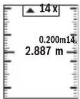
Large numbers: The measured value is displayed in an enlarged format for better legibility (see figure K). - Tape measure: The distance will be displayed visually, as with a tape measure (see figure L). Note: The distance from the marking is shown in the display in the tape measure function. The reference is not the edge of the measuring tool.
To switch on the laser beam, briefly press the measuring button (5) [ ]
Move the measuring tool until the required distance is shown at the bottom of the display.
Briefly pressing the measuring button (5) [ ] will interrupt the continuous measurement. The current measured value will be shown at the bottom of the display. Pressing the measuring button (5) [ ] once more will start the continuous measurement again.
Continuous measurement automatically switches off after four minutes.
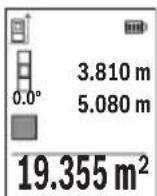
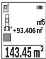
Area measurement
Select the area measurement mode.
46 | English
Then measure the width and length one after the other as with a length measurement. The laser beam remains switched on between the two measurements. The distance to be measured flashes in the indicator for area measurement
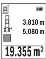
The first measured value is shown at the top of the display.
After the second measurement has been completed, the area will be automatically calculated and displayed. The end result is shown at the bottom of the display, while the individual measured values are shown above it.
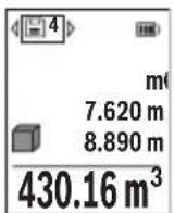
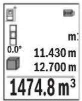
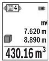
Volume measurement
Select the volume measurement mode
Then measure the width, length and depth one after the other as with a length measurement. The laser beam remains switched on between the three measurements. The distance to be measured flashes in the indicator for volume measurement
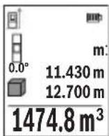
The first measured value is shown at the top of the display.
After the third measurement has been completed, the volume will be automatically calculated and displayed. The end result is shown at the bottom of the display, while the individual measured values are shown above it.
Indirect distance measurement
For indirect length measurements, three measuring modes are available. Each measuring function can be used for determining different distances.
The indirect distance measurement is used to determine distances that cannot be measured directly, due to an obstacle that would impede the path beam or the absence of a target surface that could serve as a reflector. This measuring procedure can only be employed vertically. Any horizontal deviation will lead to measurement errors.
Note: Indirect distance measurement is always less accurate than direct distance measurement. For application-related reasons, measuring errors can be greater than with direct distance measurement. To improve the accuracy of measurement, we recommend the use of a tripod (accessory).
The laser beam remains switched on between the individual measurements.
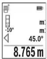
a) Indirect height measurement (see figure E)
Select the indirect height measurement mode
Ensure that the measuring tool is at the same height as the lower measuring point. Then tilt the measuring tool around the reference level and measure distance 1 as for a length measurement (displayed as a red line).
Once the measurement is complete, the result for the required distance X is displayed in the result line (e). The measured values for distance 1 and angle α can be found in the measured value rows (d).
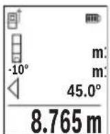
b) Double indirect height measurement (see figure F)
The measuring tool can indirectly measure all distances that lie in the vertical level of the measuring tool.
Select the double indirect height measurement mode
Measure distances 1 and 2 in succession as for a length measurement.
Once the measurement is complete, the result for the required distance X is displayed in the result row (e). The measured values for distances 1 and 2 and angle α can be found in the measured value rows (d).
Ensure that the reference level for the measurement (e.g. the rear edge of the measuring tool) remains in exactly the same place for all
the individual measurements in a single measuring process.
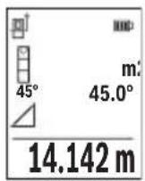
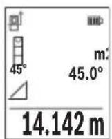
c) Indirect length measurement (see figure G)
Select the indirect length measurement mode
Ensure that the measuring tool is at the same height as the required measuring point.
Then tilt the measuring tool around the reference level and measure distance 1 as for a length measurement.
Once the measurement is complete, the result for the required distance X is displayed in the result row (e). The measured values for distance 1 and angle α can be found in the measured value row (d).
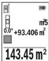
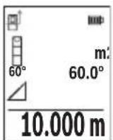
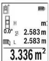
Wall area measurement (see figure H)
The wall area measurement is used to determine the sum of multiple individual areas with a common height. In the illustrated example, the total area of several walls that have the same ceiling height H but different lengths L is to be determined.
Select the wall area measurement mode.
48 | English
Measure the ceiling height H as for a length measurement. The measured value is displayed in the top measured-value line. The laser remains switched on.
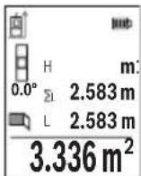
Then measure the length L1 of the first wall. The area is automatically calculated and displayed in the result line (e). The last measured value for length can be found in the bottom measured value line (d). The laser remains switched on.
Now measure the length L2 of the second wall. The individual measured value displayed in the measured value line (d) is added to the
length L1 . The sum of the two lengths (displayed in the middle measured value line (d)) is multiplied by the saved height H . The total area value is displayed in the result line (e).
You can measure any number of lengths L× , which will be automatically added and multiplied by the height H . The requirement for a correct area calculation is that the first measured length (for example the ceiling height H ) is identical for all sub-areas.
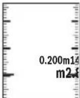
Stake out function (see figure I)
The stake out function repeatedly measures a defined length (distance). These lengths can be transferred to a surface, for example to enable material to be cut into pieces of equal lengths or to install stud walls in a drywall construction. The minimum adjustable length is 0.1m and the maximum length is 50m .
Note: The distance from the marking is shown in the display in the stake out function. The reference is not the edge of the measuring tool.
Select the stake out function
Use the button (6) [+ ] or the button (3) [-] to set the required length.
Begin the stake out function by pressing the measuring button (5) [ ] and slowly move away from the starting point.
The measuring tool continuously measures the distance to the starting point. The defined length and the current measured value are thereby displayed. The lower or upper arrow displays the shortest distance to the next or last marking.
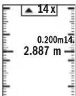
The left factor specifies how many times the defined length has already been reached. A green measured value indicates that a length has been reached for marking purposes.
A blue measured value indicates the actual value when the reference value is outside the display.
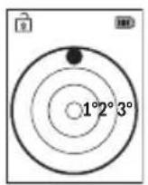
Grade measurement/digital spirit level
Select the inclination measurement/digital spirit level
The measuring tool automatically switches between two states.
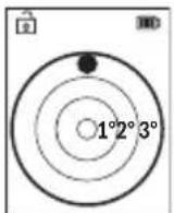
The digital spirit level is used to check the horizontal or vertical alignment of an object (e.g. washing machine, refrigerator, etc.).
When the inclination exceeds 3° , the ball in the display lights up red.
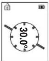
Grade measurement is used to measure a slope or incline (e.g. of stairs, railings, when fitting furniture, laying pipes, etc.).
The left-hand side of the measuring tool serves as the reference level for grade measurement.
Memory value display
The value or end result of each completed measurement is automatically saved.
Maximum 30 values (measured values or end results) can be retrieved.
Select the memory function [1]
The number of the memory value is shown at the top of the display, the corresponding memory value is shown at the bottom and the corresponding measuring function is shown on the left.
Press the [+] button (6) to browse forwards through the saved values.
Press the [-] button (3) to browse backwards through the saved val
ues.
The oldest value is located in position 1 in the memory, while the newest value is in position 30 (when 30 memory values are available). If a further value is saved, the oldest value in the memory is always deleted.
Deleting the memory
To delete an individual memory value, select this value (see "Memory value display", page 49). To delete, first press the on/off/back button (8) [Fand confirm this by pressing the (2) [Func] button.
To delete all the contents of the memory, press the (7) [ button and select the function. Then press the (6) [+] button and confirm this by pressing the (2) [Func] button.
50 | English
Adding/subtracting values
Measured values or end results can be added or subtracted.
Adding values
The following example describes the addition of areas: Measure an area as described in the "Area measurement" section Area measurement.
Press the [+] button (6). The calculated area and the + symbol will be displayed.
Press the measuring button (5) [ ] to start another area measurement. Measure the area as described in the "Area measurement" section Area measurement. Once the second measurement is completed, the result of the second area measurement is displayed be
low. To show the end result, press the measuring button (5) [ ] once more.
Note: In the case of a length measurement, the end result is displayed immediately.
To exit addition, press the [Func] button (2).
Subtracting values
To subtract values, press the button (3) [-]. The subsequent steps are the same as for the section on adding values.
Deleting measured values
Briefly pressing the on/off/back button (8) [ will delete the last measured value in all measuring functions. Repeatedly pressing the on/off/back button (8) [ briefly will delete the measured values in reverse order.
Practical advice
The measuring tool is equipped with a wireless interface. Local operating restrictions, e.g. in aeroplanes or hospitals, must be observed.
General advice
The reception lens (15) and the laser beam output (16) must not be covered during the measuring process.
The measuring tool must not be moved during a measurement (with the exception of the continuous measurement and grade measurement functions). For this reason, place the measuring tool against or on a firm surface whenever possible.
Influences on the measuring range
The measuring range depends on the lighting conditions and the reflective properties of the target surface. For better visibility of the laser beam in bright extraneous light, use
the laser viewing glasses (20) (accessory) and the laser target plate (19) (accessory) or shade the target area.
Influences on the measurement result
Due to physical effects, the possibility of inaccurate measurements when measuring various surfaces cannot be excluded. These include:
- Transparent surfaces (e.g. glass, water)
- Reflective surfaces (e.g. polished metal, glass)
- Porous surfaces (e.g. insulating materials)
- Structured surfaces (e.g. roughcast, natural stone).
If necessary, use the laser target plate (19) (accessory) on these surfaces.
Inaccurate measurements are also possible where the laser is pointed at target surfaces diagonally.
Layers of air at different temperatures and indirectly received reflections can also influence the measured value.
Checking accuracy and calibrating the grade measurement (see figure M)
Regularly check the accuracy of the grade measurement. This is accomplished by means of a reverse measurement. To do this, lay the measuring tool on a table and measure the inclination. Turn the measuring tool by 180° and measure the inclination again. The difference between the displayed values must not exceed 0.3° .
In the event of larger deviations, you have to recalibrate the measuring tool. To do so, select in the settings. Follow the instructions on the display.
We recommend that you perform an accuracy check and if necessary a calibration of the measuring tool after extreme temperature variations and after impact to the tool. After a temperature variation, the measuring tool must adjust to the ambient temperature for a while before calibration is performed.
Accuracy Check of the Distance Measurement
You can check the accuracy of the measuring tool as follows:
- Choose a measuring section of approx. 3 - 10m in length that is permanently unchanged, the exact length of which is known to you (e.g. room width, door opening). The measurement should be taken under favourable conditions, i.e. the measuring section should be indoors and the target surface for the measurement should be smooth and reflect well.
- Measure the section ten times in succession.
The deviation of the individual measurements from the mean value must not exceed ± 4mm over the entire measuring section in favourable conditions. Record the measurements in order to be able to compare the accuracy at a later date.
52 | English
Working with the tripod (accessory)
The use of a tripod is particularly necessary for larger distances. Place the measuring tool with the 1/4'' thread (14) on the quick-release plate of the tripod (21) or of a commercially available camera tripod. Tighten it using the locking screw of the quick-release plate.
Set the reference level for measurements with a tripod in the settings (see "Selecting the reference level (see figure B)", page 43).
Belt clip (accessory) (see figure N)
With the belt clip (17), the measuring tool can be conveniently secured to your belt.
Error message
If a measurement cannot be performed correctly, the "Error" message will appear in the display. Start the measurement again.

The measuring tool monitors correct functioning in every measurement. If a defect is detected, the display will indicate only the symbol shown opposite and the measuring tool switches itself off. In this
case, have the measuring tool checked by an after-sales service agent for Bosch power tools.
Maintenance and Service
Maintenance and Cleaning
Store and transport the measuring tool only in the supplied protective bag (23).
Keep the measuring tool clean at all times.
Never immerse the measuring tool in water or other liquids.
Wipe off any dirt using a damp, soft cloth. Do not use any detergents or solvents.
Take particular care of the reception lens (15), which must be handled with the same level of care you would give to a pair of glasses or a camera lens.
If the measuring tool needs to be repaired, send it off in the protective bag (23).
After-Sales Service and Application Service
Our after-sales service responds to your questions concerning maintenance and repair of your product as well as spare parts. You can find explosion drawings and information on spare parts at: www.bosch-pt.com
The Bosch product use advice team will be happy to help you with any questions about our products and their accessories.
In all correspondence and spare parts orders, please always include the 10-digit article number given on the nameplate of the product.
Great Britain
Robert Bosch Ltd. (B.S.C.)
P.O.Box 98
Broadwater Park
North Orbital Road
Denham Uxbridge
UB95HJ
At www.bosch-pt.co.uk you can order spare parts or arrange the collection of a product in need of servicing or repair.
Tel. Service: (0344) 7360109
E-Mail: boschservicecentre@bosch.com
You can find further service addresses at:
www.bosch-pt.com/serviceaddresses
Transport
Lithium-ion batteries are subject to the Dangerous Goods Legislation requirements. The batteries are suitable for road-transport by the user without further restrictions.
When shipping by third parties (e.g.: by air transport or forwarding agency), special requirements on packaging and labelling must be observed. For preparation of the item being shipped, consulting an expert for hazardous material is required.
Dispatch battery packs only when the housing is undamaged. Tape or mask off open contacts and pack up the battery in such a manner that it cannot move around in the packaging. Please also observe the possibility of more detailed national regulations.
Disposal
Measuring tools, rechargeable/non-rechargeable batteries, accessories and packaging should be sorted for environmental-friendly recycling.
Do not dispose of the measuring tools or rechargeable/non-rechargeable batteries with household waste.
Only for EU countries:
According to the Directive 2012/19/EU, measuring tools that are no longer usable, and according to the Directive 2006/66/EC, defective or used battery packs/batteries, must be collected separately and disposed of in an environmentally correct manner.
54 | Français
Battery packs/batteries:
Li-ion:
Please observe the notes in the section on transport (see "Transport", page 53).
François
Robert Bosch (France) S.A.S.
www.bosch-pt.com/serviceaddresses
Transport
www.bosch-pt.com/serviceaddresses
Transporte
www.bosch-pt.com/serviceaddresses
Transporte
www.bosch-pt.com/serviceaddresses
Trasporto
www.bosch-pt.com/serviceaddresses
Vervoer
Bosch Service Center
Telegrafvej 3
2750 Ballerup
På www.bosch-pt.dk kan der online bestilles reservedele eller oprettes en reparations ordre.
TIf. Service Center: 44898855
Fax: 44898755
E-Mail: vaerktoej@dk.bosch.com
www.bosch-pt.com/serviceaddresses
Transport
Foratt lamna addition,tryckpknappen (2) [Func].
Subtrahera varde
For subtrahering av varden, tryck pa knappen (3) [-]. Proceduren ar den somma som vid "Addera varden".
Raderamätvarden
Bosch Service Center
Telegrafvej 3
2750 Ballerup
Danmark
Tel.: (08) 7501820 (inom Sverige)
Fax: (011) 187691
Du hitter fler kontaktuppgifter till service har:
www.bosch-pt.com/serviceaddresses
Transport
www.bosch-pt.com/serviceaddresses
Transport
www.bosch-pt.com/serviceaddresses
Kuljetus
www.bosch-pt.com/serviceaddresses
Metaopà
Oi matapiec iovtwv Aioiu unokivta otic anai thoeic tnc vuo geiaac yia enikivduva npoiovta. Oi matapiec mnpouv va metapepeoov obikw c an to xipotn xwpic aalouc opouc.
'Otav, oouc, oi pataie c anootelovt a anp tiouc (n.x. aeponopikw c n e taipia metaapopov) npenei va npouvta diapopec idaiirepec anaitnoeic yia tn ouokeuaia kai tn onuavon. Eow npenei, kata nyn npoeotuaia tou teaxiou anoToa hcv zntnthetai onwohnote kai n oumbouan evoc eiokou yia enikivduva aya.
AnooteTic mntapiec ovo otav to nepiBna eivai dikto. Koata Tc yuvc enapec me kooti Kaia kva ouokeuaTe nnu mntapia kat a Toio Tpno, wote autn va unv kouvietae oea ot nuokceuaia. Papaakoume va laaavete enionc unovn oac kal tuxov nio auotnpec eovikec diataeic.
Anoupon

Ta opyava eptponc, o enavaopntojevec mnatapiec/umatapiec, ta
eapntmuata kai oi ouakeuaoe c npenei va avakukawovtal pToTPOIko
npoc to nepiBaAiov.
Mn pixvete ta opyava metpnonc kai tic enavaopntojevec mnatapiec/ mnatapiec ota oikiaka anoppipmuata!
Móvo yia xωpec tnc EE:
www.bosch-pt.com/serviceaddresses
Nakliye
Robert Bosch Sp. z o.o.
www.bosch-pt.com/serviceaddresses
Transport
Bosch Service Center PT
KVapence 1621/16
692 01 Mikulov
www.bosch-pt.com/serviceaddresses
Preprava
www.bosch-pt.com/serviceaddresses
Transport
Litiovo-ionove akumulatory podliehaju nariadeniam o nebezpecnych nabladoch. Tieto akumulatory smie pouzivatei naradia prepravovat po cestach bez dalsich opatreni.
| Bluetooth® | Bluetooth® (4.2 low-energy)H) | Bluetooth® (4.2 low-energy)H) |
www.bosch-pt.com/serviceaddresses
Szallitas
Cpok cnyx6b1 n3dJIHn
Cpok cnky6bI n3dennn coctabnaret 7 neT. He pekomehnyetcK ekcnnyatauHn no nCTeueHHN 5 let XpaHeHHN C daTb H3rTOBHeHHN 6e3 npedBapHTenbHOn npOBepKn (daty n3rTOBHeHHN CM. Ha 3tIKeTKe).
Ipeueheb KpHTnuecknx OTka3OB N Oun6oHbIe DeicTBna nepcohana nn nnonb30BaTeTn
- He HcNoIb3OBAbT pRn IoRbIeHnn DbIMa HenoCpeIcTBeHNO 3 KOpTyca N3dEINr
-He HcIOnb30BaTb Ha OTKpbITOM IpoCTpaHCTBe BO BpeMЯdoXJa(B paCnblraEmoB
-He BKNIOuATb npn nonaHaHH BOdBiB KOpnyC
Kpntepnn ppeenbhbix coctoHHN
I3o6paXeHHbIe coCTaBHbIe yactn
Hymepaun npedctabnEHbIX COCTaHBIX qacte BblONHeHa NO H3O6paXeHNIO N3MepnTeNbHO INCTpyMeNTa Ha CTpaHnce CnnIOCTpaUmaN.
(1) Khonka Bluetooth®
(2)ФункционаьногКногka[Func]
(3)KHONKa «MmHyc/BnEBo»[-]
(4) Dnncnn
(5) KhoNka n3MepeHnra [
(6)KhONKa《nHOC/BnpaBO》[+]
(7) KHONka OCHOBHbIX HAcTpoEK [
(8) BbIKIIOuATEnb/KNHONKa《Ha3aN》[
(9) Пожина ремшka дя поскн
(10) Ppeynpeintbna Ta6nka na3epHoro n3nyeHHa
Pycckn|371
(11) CepnHbH Homep
(12) ΦИКСАТОР КрblшкВ 6aTapeHOrO OТсЕКа
(13) Kpbuika 6aTaapeHoro OTecka
(14) Pe3b6OBoe OTBepCTne dIaTtNa 1/4"
(15) PpHemHa JnH3a
(16) BbIXoIa3epHoroLyua
(17) 3aKIM dIg KpeJIeHnA
(18) UypynA3aKMa dJa KpeNneHnA
(19) Bn3npHa Mapka nlaIa3epHoro lyuaA
(20) Oukn dna pa6oTbI c na3epHbIM HhCTpyMeHTOM
(21) ⅢTaNtB
(22) PemeokДЯппepeHOCKnA
(23) 3aunTHbIyueXoI
(24) NHTN-NOHHbI aKKyMylTOpHbI 6nok
(25) ΦИКСАТОР ДИТП-ИНHОНоаKKуMЛЯТОрно6лOKa
(26) Ka6eIb USB Type-C®A)B
(27) Kpbiuka rHe3da USB Type-C
A) N3o6paXeHHbIe HnH ONuCAHbIe PpHaADJIeXHOCTH He BXOJrT B cTaHApTHbI O6beM NOcTABKn. IOnHbI accOpTmEHT npHaADJIeXHOCTe Bbl HaJeTe B haWe IporpamMe npHaADJIeXHOCTe.
B) USB Type-C® n USB-C® ABJHOTcT TOPROBbIMN MapKaMn OpraHH3aunn «USB Implementers Forum».
HnKaTopb1(Bbl6p)
(a) IIOCKOCTb OTCueta npHn3MepeHHN
(b) CoctoHne coeHHeHH

Bluetooth® aKTHBnPOBaH, CBa3b He yCTaHOBNeHa

Bluetooth®akTHBnPOBaH,CBY3b yCTaHOBNeHa
(c) HndkaTop 3apXeHHoCTn 6aTapei
(d) 3HaueHnHaMepeHHa
(e) Pe3ynbTaT
(f) Pekn m n3mepeHn
(g) HndnKaTOp yrna HaKIOHa
Bosch Power Tools 160992A4ZJ| (14.10.2020)
372|Pycckn
(h) Ctpoka coctoHHa
(i) HndnKaTOp «Pekmbl n3MepeHn
(j) HndnKaTOp «OcHOBHbIe HaCTpOIKN»
(k) HndnkaTOp «Ppoue HaCTpOKn
TexHnueckne daHHbIe
N3BneKaIte 6aTapeH Hn AkKymyIaTOpbI H3 N3MepHTeNbHO rHcTpMeHTa, ecnn npOdoJXHTeNbHoe Bpem He 6ydeTe pa6oTaB c Hm. Pn dInTeNbHOM xpa-HeHHN BO3MOxHa Kopp03n Hn CamopazraJa Ka 6aTapeek/AKKymyIaTOphbIX 6aTapei.
YcTaHOBka/3aMeHa NHTn-NOHOro aKKymyIaTOpHoro 6NoKa (npHaIeXHoCTb)
YcTaHOBHTe HHTH-NOHHbI aKKyMylrTOpHbI 6JOK (24) (CM. pnc. A).
UTo6bI h3BLeue bHTH-NOHHbI aKKyMylrTOpHbI 6JOK (24), HaKMITE Ha qKCaTOp (25)
Hn3BLeKeITe aKKyMylrTOpHbI 6JOK.
Pa6ota c nHcTpymeHTOM
3apnKa nHTn-NOHOro aKKymyIaTOpHOro 6noKa (npHaadJeKHOCTb)
Yka3aHHe: AkkymyIaTOPHa 6aTape nOCTaBnIeTcB uactNuHO 3apJxHOM COCToHnn. B cIeHX peAIN3aunn noHOn eMKocTHn akKymyIaTOPHo 6aTape en ee Heo6xoHmO noHOCbIO 3apdntb B 3apdHOM yCTpOHCTBe nepei nepBoN EKcnlyatauNe.
THe3do USB dnia noKnioueHnKa6eNa USB (26), a TaKKe HndKAtop 3apAKn HaxOaTcra nD KpbIshKo THe3da USB (27) Ha NHTN-NOHOM aKKyMnyTOpHOM bloKe (24) (npnHaJneXHoCTb).OTKpoTe KpbIshKu THe3da USB (27) n noKNIouHte Ka6eNb USB (26).
Bo Bpem 3aprKn HndnKaTOp 3apxKeHHocn 6bapeH Ha dncnlee MoKet OTnuaTbcr O T aKTInuecko CTeneH 3apxKeHHocn nHTn-NOHOrO aKKymyIaTOpHOrO bNoka (24).
Korda nHTHn-HOHbI aKKyMylTOpHbI 6nok (24) 3apJxeh nonHOCTbIO, HndNKaTOp 3apdKNrOpHT 3eJeHbIM CBETOM.
Bo Bpem 3apRKn HndnKaTOp 3apRKn Tropnt XeNTbIM CBeTom. KpacHbN INnKaTOp 3apRKn Yka3bIbaeHa HeCOOTBeTCTBHe 3apRnHO HaPRAKeHn Nn 3apRnHO TOkA.
BkIoueHne 3neKtpOHnHcTpymeHTa
He octabnIte n3MepHTenbHbIM HnCTpyMeHT 6e3 npncMOtpa N BblKIOuayTe n3-MepHTenbHbIM HnCTpyMeHT nocne HcnoNb3OBAHnA.ДpyTne IInca MOryt 6bITb OcJIeJIeHbI Na3epHbIM LyvOM.
3aunuaTe H3MePHTeBHBHINHCTpyMeHT OT BnARN npAmbix CONHeuHbIX Nyuei.
He noDBepraIte H3MepHTeBbHbI HHCTpyMeHT BO3DeIcTBIO 3KCTpeMaJIbHbIX TemnepaIpyN TemnepaTyphbxN nepenadOB. Hanpimep, He octabnIte erO ha dInTeBHO BPEMA B ABTOMo6nIe. Pn 3NaHTeBbHbIX KOleBaHNx TemnepaTybl Npeed Haayanom HCNoJIb30BaHHa DaIte TemnepaType H3MepHTeBHO HHCTpyMeHTa CtaBnIN3npoBaTbcA. 3KCTpeMaJIbHbIe TemnepaTybl N TemnepaTyphbl e nepenadMoYr OTPnUaTeBHO BIIaTb Ha ToHOCt b H3MepHTeBHO HHCTpyMeHTa.
H36eraIte CnIbHbIX ToUkOB n NaeHnna H3MePHTeBHO HHCTpyMeHa. Nocne CnIbHbIX BHeIHHX BO3JeIcTBn Ha H3MePHTeBn HNCTpyMeHt peKOMeHdyETc npOBepHb ero ToUHocTb, npexJe cem npoJOnKaTb pa6OtaB c Hm (cm..Piobepka ToUHocTn KAn6pOBka npn H3MepENn yrna HAKIOHa (cm.pnc.M), CtpaHnca 387) n (cm..Piobepka ToUHocTn H3MepENn pacctOHHra", CtpaHnca 387).
N3mepntbHbI HnctpyMeHT o6OpyIOBaH paHNOHTepfchom. Co6HouaTe MeCThBle OrpaHnueHnno nO npMHeHHo, HAp., B camoneTaX Hn 60nbHnax.
He npabnTe na3epbIyuHa IIOe HIN XHBOTbIX He cMOtpte camB Na3epbIyu, B TOM uCne Hc 6oNbwoO paCCToHHa.
Yka3aHne: O6bIuHO 3HaueHne H3MepeHHra OTo6paXaETcRA uee3 0,5 c, MaKcHmym ueep3 np6n.4 c. IpoJIoJXHTeNbHOCTb H3MepeHHra 3aBNCHT OT pacCTOAHNRA, OCBeUeHHoCTn IOtpaXaTeNbHO CNOC6HOCTn CEHN. IocNe OKOHuaHHra H3MepeHHra Na3epHbI Lyu ABTO-MaTHueCKn OTKnIOUaETcR.
BbI6Op nIOockoCTn OTCuTea (cM. pnc. B)
Pn n3MepeHH Bb MoKTe BB6paTb Ondy n3 Tpex PnOcKCTe OTcUeta:
-3aHnKpaH3MepeHbHOrO HcTpymeHTa (Haepmep, npn npNKdaBbAHnn K cTeHAM),
- npeHn Kpa H3MepntbHOro HHCTpyMeHTa (HaPnMep, npn H3MepeHnx OT Kpa cTOna).
- cepenha pe3b60BOrO OTBepTna (14) (HaPnMep,ДЯИЗмepHn CO WtAHBOm) Iy BbIbopa nloCKoCTn OTCuEta HaxMMte KhoNky (7) [3aTeM C NOMOUsIO KHOKN I3MepeHn (5) [▲] INI KNOKn (2) [Func] BbIbepNTe HactpoNkY «IIIOCKoCTb OTCuEta». Iocne 3TOrO c NOMOUsIO KhoNKn (6) [+] INI KNOKn (3) [-] BbIbepNTe Heo6xOdmyIO nloCKoCTb OTCuEta. Ipr KaJdOM BkJIoueHn IN3MepeTebHOrO IHCTpyMeHTa B KaueCTBe ILOCKoCTn OTCuEta yCTaHOBNeH NocJeHn BblpaHHb BapNaHT.
MeHIO «HaCtpoIKN» (cM. pnc. C)
UTo6bI IpeeHTB MeHIO 《HaCTpoKn》(j), HaxMnte KhoNky (7) [
BbIbePnte c nOMOuKHOKN (6) [+] nN KHOKN (3) [-] Tpebyemyo hAcTPOy u NnD- TBepNTe KHOKNo (5) [A] nN KHOKNo (2) [Func].
BbIbePte Tpe6yeMyo yctaHOBky C NOMOu bIO KhoNKn (6) [+] nHn KhoNKn (3) [-] nnoTBePnte KhoNkOu H3MepeHn (5) [▲] nHn KhoNKn (2) [Func].
UTo6bI BbInn H3 MeHIO «HaCtpoKn》,HaxMITE BbIKNoaTeIb/KhONKy «Ha3aI(8)[B]OCTynbl CneDyIoune yctaHOBN:
-BkIIOueHne/BbIKIOueHne 3Byka
- BkIIOUeHne/ByIKIOUeHne Bn6paunOHbIX CnIHANOB:BaKOpOTKHX Bn6paunOH HbIX CNrHaJa CBnTeBCTBYOT 06 yCneuHO npOn3BeEHOM n3MepeHH; DaNHHbIX Bn6paUNoHHbIX CNrHaJa CBnTeBCTBYOT 06 OUn6Ke npn npOn3BeEHn n3MepeHHa.
-ⅡoDCBETKaIINCIIe
- PexHM 3KOHOMH 6aTapen :Bn BkIIOueHHOM pexHMe 3KOHOMH 6aTapen 3ByKO-BbIE n Bn6paUHOHHBe CnHaJIb OTKnIOueHb, a npKocTb DnCnIIe CHnxHe. TaKIM o6pa3OM yBENuHBaETcBpeMa pa60tbl Ha OndH 3apJKe.
-IM3MeHeHne eHNHcbln3MepeHnft/m
-HactpoiKa 3bika
- PRO360 -propebyetcnapbohaaibhagakTbuaqna. IpepaDaanHbIX BO3MOxHa TOnbko npn NOMOuN COOTBETCTByoUeTo npIoXeHHN npOrpAmMbI dIg PIK. Pocne 3amHe batape nCleDyET OOnn pa3 BKIOuHTb H3MePHTbHbIN HcTpymENT dIaZnycka PRO360. PRO360 MoXHO BJIIObON MOMENT CHOBA OTKIOUHTb. Boone no-dpo6HyIO INΦOpMaunO o PRO360 BBi HaJeTe Ha caIte: www.pro360.com.
-Инфорmaцьо npn6ope i
-3aBODCKHe HacTpoiKn
Pexkmbi n3MepeHH
H3-3a 0n3nuecknx 3ofoeKTOB He NCKIIOUeHO, yTo npu n3MepeHH Ha pa3nHbIX NOBepxHOCTAX MOyT BO3HNKHyTb OUn6Kn n3MepeHH. K TAKIM NOBepxHOCTM OTHOCATC:
- npo3paHbIe NOBepxHOCTn (HaNP, CTeKIO, BOJa),
-3epkaIbHbIe NOBepxHOCTn (HaPp., nonipobaHHbI MeTaN, cTeKNo), - nopnctbIe NOBepxHOCTN (HaNP., H3OJIaUNOHbIe MaTePnaJIbI)
- CtpyKtpynpoBaHHbIe NOBepxHocTn (HaNP., CtpyKtpynpoBaHHa HHTyKaTpyKa, HaTpaNbHbIKaMeHb).
Ipn Heo6xOIMOCTHn HcNoB3yIte Ha 3TNX IOBepxHOCTx BN3NpHyIO Mapky IINa3epHoro Nyua (19) (npHaadneKHOCTb).
PnKOCOM HabeHenn Ha ueB BO3MOXHbOuH6Kn.
Bo3nyHbIe cnoC pa3nHoi TempeatypoN/nn He npAme OTPaKeHne TaKke MOryT OtpuateNbHO NOBnraTb Ha n3MepReMeO 3HaueHne.
PpOBepKa ToUHcTn KaHb6PoBkA npn H3MepeHHy rHa KaHNoHa (cm. pnc. M)
Perynphno npOBepnTe toHocThb n3MepenHa HkNoHa. 3TO OcyuceCTBnaeTcnyTe m3MepeHn B DByx HnPaBHeHnx (TuDa n o6paTHo).IpyaTO rOIOXnTe n3MepntbHbIn HHCTpymENT Ha cToI n3MepbTe yroHnKNoHa. POBepHnTe n3MepntbHbIn HHCTpymENT Ha 180° n ChOba n3MepbTe yroHnKNoHa. Pa3HnCa oTo6paXaemoro 3NaueHnE He doJHKHa npeBbIaTb MaKc. 0,3°.
Pn 60nbux OTKNoHeHnx H3MepeTebHybI INHCTpyMeHT CneyET OTKaHb6poBaTb 3aHO Bo. Ira 3TOBO b6epTe B NaCTPOkax. CneyuTe yka3aHnM Ha dnCnnee.
Iocne cInbHbIX nepenadOB TemnepaTypbI nOcNe TOUKOB Mbl peKOMeHyem IpOBecTH npOBepKy ToUHOCTN I npn Heo6xOAnMOCTN pOn3BecTN KAn6bpOBky H3MePHTbHOro HHCTpyMeHTA. PpN nepenadax TemnepaTypbI daTte N3MePHTbHOMy HnCTpyMeHTy Cta- 6nnHn3npoBaTb CBOIO TemnepaTypy, npexJe Yem npOn3BoDntb erO KaIN6bpOBky.
PpOBepka ToUHOCTn H3MepeHna pacCToAHNA
ToHocTh H3MePHTeBHO HO HcTpymeHTa MOxHO IpOBepHTb CneDyUoM O6pa3OM:
-BbIbepnte He MeHAnuCn C TeueHem BpeMeHN yuaCTOK nnHOJ npm. 3-10 M, DnHa KOTOPoTo TOHNO h3BeCTHa (HaNP., uHrpHa NOMEUEN, DBepHOJ npoem). H3-MepeHne cJeNyET PPOBOHTb npi 6bIaROpNpTbIX YcNoBHX, T.e. yuaCTOKdoJxHe HaXoINbCR B NOMEUEN IN NOBepxHOCTb ceNN DoJXHa 6bITb IJaIKoN XOPOJO OTPaKaTb.
www.bosch-pt.com/serviceaddresses
TpaHcnpOpOBKa
HaIHTH-NHOHbIe AKKymyIaTOPbIe 6aTapeH pacnpoCTpaHraIOc Tpe6oBaHHB OTHOWeHH TpaHCnOpTnPOBKn ONaChbIX rpy3OB. AKKymyIaTOPbIe 6aTapeH MOrY npeEBo3ntbcr CamMM NOb30BaTeJem ABTomO6HbHbIM TpaHCnOPTOM 6e3 Heo6xOAnMoCTn Co6NIOdeHH NDOONHHTeJIbHbIX HOpM.
Pn nepebo3e C npBneHem TpebX Nuc (Haep.: camoJeTOM nN TpaHCnOpTHbIM 3KcneIHTOPOM) Heo6xOJMo cobIoDaTb oc6bIe Tpe6oBaHnK ynpaKOBKe H MapKnpoBKe. B 3tOM cnyae npn noDrotOBKe rpy3a K OTnpaBKe Heo6xOJMo yacthe 3KcpeptA NO onacHbIM rpy3am.
OtnpaBnIte aKKymyIaTOHyIO 6batapeIO TOnbKO C HeNOBpeXdeHHbIM KOpnycom.3aKJIeIe OTKpbITbIe KOHTaKTbI N yNaKyIte aKKymyIaTOHyIO 6batapeIO TAK, YTo6bl OHa He nepemeUanac BHyTpN yNaKOBKn. IoxaanyCTa, CObIouaTe TaKKe BO3MOxHbIe DOnONHHTeNbHbIe HaunOHaNbHbIe npednncAHn.
yTnnn3aun
H3mepntbHbI HnCTpyMeHT,akKymyTOp/6aTapeiKn, npHaadJeXHOCTN uNaKOBky HxKHO CdaBaTb Ha 3KoJOnrueeCKN UcTyo yTHIN3aUIO.
He BbIbpaCbIbAaTe aKKyMylrTopHbIe 6bTapeN/6bTaapeKn B 6bITOBoMycop!
Tolbko dIra cTpaH-ueHOB EC:
B COOTBETCTBHN C EBPOENCKO INHepeKTHBOI 2012/19/EU HeoHbIe H3MepHTbHbIe np6op IN B COOTBETCTBHN C EBPOENCKO INpeKTHBOI 2006/66/EC HeoHbIe Hn OTcLyXHBWNE CBOI cPOK aKKyMylTOpHbIe 6aTapeN/6aTapeNk DoJxHbI co6HpTaBC pa3-DeNbHO n CdaBaTbc Ha 3KOLOrHuCck NcTcyo peKynepaunIO.
Bosch Power Tools 1609 92A 4ZJ | (14.10.2020)
390|YkpaIHcbKa
AkkymyIaTOpHbIe 6aTapeu/6aTapeuKn:
ЛNTи-нOHOBbie:
IoxaanyiSta, yuHTbBaIte yka3aHnB pa3dene "TpaHcnpTnpOBKa" (cm. ,TpaHCnpTnpOBKa", CtpaHnca 389).
YkpaIHcbka
Bka3iBkn 3 Texhikn 6e3nekn

IpoHTaTe BcIBk3iBKn iDopmMyTecn ix, 06 npauOBaTH 3 BmipOBAHbHM IHCTpymeHOM 6e3neuHO Ta HadiHo. BkOpHCTaHH BmipOBAhBO HO IHCTpymeHa 6e3 DOpMaHH uX IHCTpyKciM oKe np3BeCTn Do noWkoJxehn ITERPOBaHI 3axCHnx Mexahi3MiB. HikOnn He doBoDbte nonepeJxByaBbHi
Ta6nukn ha BmipobanbHomy iHctpymeHTi do HeBni3HaHHocTi. IO6PE 36EPIaTE UI HCTPYKUII I NEPEDABAHTE IX PA3OM 3 INPEDAUEIO BmIPOBaIbHOI IHCTPymeHTY.
06epexho - BHKOpHCTAHHa 3ac06iB 06cnyroByBaHHia HAcTPOOBaHHa, 0o Biip3HnOtbcra BId 3a3HaueHnx B ciin HcTpyKci, a6o BHKOpHCTAHHa D03BOeHHx 3ac06iBy Heo3BoneHH cnoCi6, MoKe npH3BoHNTn Do He6e3neHOro BnNBy BnnpomIHOBaHHa.
BHMipIOBaIbHn IHcTpMeHt NoCTaAcTbc3 NonepeKxyBaIbHO TO TabNueKOIO na3epHoro BnnpOMiHOBAHn (BOHa No3HaueHa Ha 306paXeHHI BmIPIOBaIbHO rIHcTpMeHTa H cToPiHui 3 MaIOHKOM).
Aektoeknt nonepexyBaIbHOI Ta6nukn Ia3epHoro BnnpomihOBAHHaHncAHn He MOBO Baoi KpaIH, nepe nepuM 3anyckOM Bekcnnyataio3akneTe II haknekoIO Ha MOBI Baoi KpaIH, 0BxOHTb y KomnneKTNoCTaayHH.
He HapabnIte na3epHn npomihb Ha IIOeH a6o TBapHn, i cami He nBItbcnHa npamn a6o BiO6paXyBaHn na3epHn npomihb. Bin MoKe 3acInHnIHnx IIOe, cnpuHHnHeUaChi BnpanKn a60 nowkOHTn Oui.
Y pa3i notpannaHHa3epHoro npomeHa B 0KO, HABMnche 3anlouitb oui i BiDpa3y BiBepHITbcra BID npomeHa.
Hiyoro He minaTe Bna3epHomy nphcTpoi.
He BHKOpHCTOByIe Okynapn dny po60Tu 3 na3epom (npnaad) k3axnci okynapn. Okynapn dny po60Tu 3 na3epom 3a6e3neuyotb Kpaue po3ni3HaBaHHa Na3epHOro npomeHIO, OndaKe 3axuAOTb BiJ na3epHOrO BNpOMIHOBAHHA.
He BHKOpHCTOByTe OKyIaRn IaPo6To3 Ja3epom (npHaadJa)K coHcE3axHChi OKyIaRn Ta He BdraTte IX, KOHN 3hAxOHTec3a KepMOM. OkyIaRn Ia Po6To3 Ia3epom He 3abe3neuYIObHN 3axHCT BiD YΦ npOMEHIB Ta noripswyIOb po3ni3HaBaHHKaNbOpIB.
BidaBaIte BmipobanbHn IHctpymeH Ha peMOHT nWe KBaIiKOBaHM 0axibzam Ta Inwe 3 BnKOpncTahHm OpriHaBnX 3anactHH. TInbKn 3a TaKnx yMOB BaW BmipobanbHn npna i naani 6ye 3annatnc 6e3neuHm.
He 03B0JnTe dIyam BnKOpncToByBaTH na3epHn BnMipOBAhBn IHcTpymeT 6e3 harny. DITN MOKyTB HeHaBMnCHe 3acnInTu Ce6e qu iHx JIOJe.
He npaioTe 3 BmipobalbHn mInctpyMeHToM y cepeoBnui, de icHye He6e3neKa Bn6yxy Bnacniok npncytoHcTi ropounx piin, ra3iB a60 nnny. Y BmipobalbHomy npnaDi MOxTy bYTBOPOBaTHcA iCKpn, BiJAKNX MOXe 3aMaTnCn nn a6o napn.
He BIXKpNBaIte akymyIaTOpHy 6aTapeH. IChye He6e3neKa KopoTKoro 3aMnKaHH.
Pn nookxehhi a6o HnpabnbH i ekcnnyatauii akymyantopho 6aataei Moke BHXoHTn nap. AkymyntopHa 6atapee moze 3aMatncb a6o Bn6yxatn. Bnycttb cbixe nobitpr i - y pazi ckapr - 3BepHITbcn do nikapr. Nap moxe npda3HOBATN dnxalbHI IJAXN.
Pn HnpabHbHomy BnKOpncTahHi 3 akymnyTopho6atapei moke notektn pHa. Ynkaite KOtakTy 3 Heo. Pn BnnaKObOMy KOtAKTi npomnte BiNoBIDhe Micue BOIO. Kso piHa notpanna B oOi, DodaTKOBo 3BepHITbcr do nikapA. AkmyIaTOPHa pHa MoKe cnpuHHn noDpa3HeHHaWKipn a6o onIKN.
TocpHmnpEmdetamn,HaNP.,rBi3dkamn a6o BHKpyTKamn,a6o npKnaadHnM 3OBHIhboi cHnn MoxHa nookodntn akymyIaTOphy 6atapeo.MoKJIbBe BHyTpIHc KOpOTke 3AMKaHHra,3aropAHn, yTBopeHHraDmY,Bb6yx a6o neperpiB akymyIaTOphOi 6atapei.
He 36epiraTe akymyIaTOpHy 6aTapeo, kkoBn Came He KopnctyeTecb, npra i3 KaHcJIepcBKMn cKpInkamn, KIOUamn, rBi3dkamn, rBNHTAMn Ta iINHMn HEBeNtHM MeTaeBmN npeMeTamn, Aki MOxTyb cnpuHHn TnepeMHKaHH KOtAKTIB. KopOTKe 3aMnKaHH MIX KOHTaKTAmn akymyIaTOpHOi 6aTaapei Moke cnpuHHrToOnIKn a60 noKexy.
BnKOpHcToByIe akymyIaTOpHy 6aTapeo IuIe y BnPo6ax BnPo6hNka.IIuIe 3a TaKnx yMOB aKymyIaTOp 6yIe 3axIuEHH BiD Hebe3neHoro nepeBaHTaxeHH.
392|yKpaIHcBka
3apJkaTe akymyIaTOPhi 6aTapei NWe B 3apJHnx npIcTpoX, peKOMeHIOBaHNbNPO6HnKOM. BnKOpNCtAHn 3apJxByBaIbHOrO npIcTpoI DnA kymyIaTOPHX 6aTapei, dIra IaNX BiH He nepeIbauEHn, MoKe npI3BOHTn Do noXeki.

3axuante akymytaopny 6atapeo BiTenna, 3okpema, Hnnp., BiD coHnHx npomeHIB, BORHIO, 6pydy, BOIN Ta BONOrn. IcHyE He6e3neKa B6xyi KOPOTKoro 3AMKAHHa.
O6epexHo! PnBnKOpHCTaHHI BmIPoBaIbHorO iHcTpymeHa 3 Bluetooth MoXnBi nepeuKOdI nIiunx npnaIbIB yctahOBok, nItakIB i MeuHnx anapatib (Hanp., KapdiocTmMyIaTOpiB, cnyxOBHX anapatib). Kpim Toro, He MOxHa NOBHCIO BHKLIouHTN MoXnBIcTB 3aBDAHNA WKOOn IIOJAM i TBapHHAM, 0o 3haxoIbTbcB 6e3nocepEni 6bn3bKocTi. He KopncTyTeCBA HmIPoBaIbHm IHcTpymeHToM 3 Bluetooth no6n3y BiD MeuHnx anapatib, 6eH3OKoNoHOK, xIMiHNx yCTAHOBOK i Tepntopi, Ha kNX icHyc He6e3neka Bb6yxib a6o moxytb npobOHTncnPiDPNBHI p6oTH. He KopncTyTeCBA HmIPoBaIbHm IHcTpymeHToM 3 Bluetooth B nIitakax. HamaraIteCn He BMNKaTH IHcTpymeHT Ha TpNBann Yac 6e3nocepEnbO KOt tina.
CnoBecn ToBapn 3nak Bluetooth® i rpaΦiHi ToBapHi 3nakn (norotnn) e 3apecTpoBaHmN ToBapHMn 3nakamn i BlaChicTo Bluetooth SIG, Inc. KomnaHia Robert Bosch Power Tools GmbH BnKOpncToBye ci cNoBechi/rpaΦiHi ToBapHi 3nakn 3a liueh3ieIIO.
(a) Ba3OBA nIooHnHa npn BnMipIOBaHHi
394|yKpaaiHcbKa
(b) CtaH 3'eHaHHa
Bluetooth® yBIMKHeHn, 3'ENHaHHn He BCTaHOBnHe
Bluetooth® yBIMKHeHn, 3'eHaHHBCTaHOBneHe
(c) 1Hdikatop 3apJxHeOCTi 6aTapeNoK
(d) Bmipai3HaueHH
(e) Pe3yIbTaT
(f) PeknBmipoBaHHa
(g) IHHaKApO KyTa Haxnny
(h) PAnOK cTaHy
(i) IHHkaia Ha dncnnei «FyHKii BmipIOBaHHA
(j) IHHkaiaHa dncnnei《OChOBHHaHaauTByaHHA
(k) Hndnkaia Ha dncnnei IHsi HanaaHTyBaHHA
Texhihidi
3akymyIaTOpHm6batapeMnHa1,2B3aJIeXHO BIDcMHOCtIMoKHa BVKOHaTH6iNbWe BmipIOBaHb,HIX36batapeKamnHa1,5B.
Iio6 BiKpnTn KpnSku Cekii DnA 6atapeoK (13), npntncHtB pfikcatop (12) i3HIMITb KpnSku Cekui DnA 6atapeoK. BcTaHObitb 6atapeuKn aOaKymJrTOPi 6atapei. PpN UcbOMy 3BepTaTe yBaRy Ha npabInbHy HAnpaBHeHicTb nOJIocIB, kC ne NOKa3aHO BCEpeHHi Cekui DnA 6atapeoK.
Ipn Hn3bKOMy cTyneni 3apJxHeOCTi baTapea a6o akymyTAOPHX 6bapea Ha nCpnei 3'ABtbcra 3aHIT aKTNauipeKMy eKOHomii 6bapei. KOn pexKm EKOHomii 6bapei aKTHBOAHn, qac poBToHa oNHOmy 3apJdi 36iInbUyeTBcA, a Ha nCpnei JXOBTM KOJIbOpom NiDCBIuyETbcra CmB0n 6bataeKn (DnB., MeHIO «HanaStyBaHHa» (DNB. Man. C)”, CToPiHKa 401).
JaKIO Ha dncnnei Bnepwe 3'ABnEcbc CnMBoN nopoXhboi 6batapeKNI, MoXHa npOBecTH
JIWe KINbKa BnMIPUBaHb. JaKIO CnMBoN 6batapeKNI nopoXhni 6bnMae cepBOHM,
NoaIbwi BnMIPUBAHn HEMOJNBI. 3amHITb 6batapeKn afo akymyIaTOpHi 6batapei.
3aBxDi MInrTe OndHocHo Bci 6batapeKn/akymyIaTOpHi 6batapei. BnKOpNCTOBynte
JIWe 6batapeKn afo akymyIaTOpHi 6batapei oDHorO BnPo6Hnka i OndHakOBoi cMHOCTi.
BnMaTe 6aTapeKn a6o akymyIaTopHi 6aTapei 3 BmIpIOBaIbHorO IHcTpymeHTa, kUTo TpNbAHH qac He 6yJeTe KOpHCTyBaTHC HMM. Pn TpNbAtonMy
36epirahhi 6atapei KaymyIaTOpHi 6atapei MoKyt b KopoDyBaTu i camop03pIaXaTnC.
BcTaHOBneHn/3amHa nii-iOHHoro akymyIaTOphoro 6noka (npnaad)
BctaTe nii-iOHHn akymyIaTOpHn 6nok (24) (nVB. Man. A).
Ipi nepwomy yBIMKHeHHI BHMipIOBaHbHO iHCTpyMeHTa Bam 6yde 3anpOnoHObaHO Bn6paTH 3pyHy MOBy IJN DHCnnEHNX NOBIDOMNeHb.
Lio6 BnMKHyTN BnMIPOBaIbHn iHCTpyMeHT, yTpMyTe BnMnKaU/KHONKy «Ha3aD» (8) [ ]
Y pa3i BmKHeHHB MIpOBAIbHOro IHCTpMeHTa 3HaueHH, IIO 3HaxOaTbCra B nAm'Ati, I HanaTuBaHH iHCTpMeHTa 36epiraOtbcra.
PpoeDpya BmipIOBaHHa
Iicra nepworo yBimKHeHH BnMipOBAHbHn IHCTpyMeHT 3haxoHtbcB PexHMI BnMIPIOBAHH IOBXHH. Ipn HAcTyNHOMy yBIMKHeHHI BnMipOBAHbHn IHCTpyMeHT 3haxoHTmETbC8 B OCTaHHbOMy BnKOpNCTaHOMy pexHMI. IJna IpeemHKaHHB I hHNI pexHM BnMIPIOBAHH HaTCHiTB KHOKNy (2) [Func]. BnBepiTB bKaHaH N peXHM BnMIPIOBAHH KHOKNO (6) [+] abo (3) [-] (INB. ,Функць BnMipOBAHH " CtopiHa 402). YBIMKHITb peXMM BnMIPIOBAHH KHOKNO (2) [Func] a6o KHOKNO BnMIPIOBAHH (5)
Дябазоовиплошнь Вмірювань дocуни Trп варiaHTN Hanaштувань (ДИВ. „Вибір 6азоови плошни (ДИВ. Мал. B)“, CtopiHka 401).
IpnCTaBTe BmipIOBaIbHn IHcTpymeHT Do 6aKaHOI BHXiHOI TOKKn BmIpOBAHH (HaNP.,do CTiH).
Bka3ibKa: RAIO BHMIPHOBAJIbHn IHCTpMeHT yBIMKHeHn 3a DOIOMOIO BUMNKaHa/ KhoNKn «Ha3aD (8) [2], KOPOTKOUacHO HaTNCiHb Ha KHOKNy BHMIPHOBAHHa (5) [A], 106 yBIMKHyTN na3ep.
Uo6 3iINCHNT BHMIPIOBAHHa,HaTNCiTB Ha KHONKY BHMIPIOBAHHa (5)[PiCna zuBOI na3epHn npOMIHb BUMNkaETbcra.ДЯ nOdaJIbUoro BHMIPIOBAHH NOBTOPIb uO npOceDpy.
He cnpyMOByTe na3epHn npomInb Ha IIOe i TBapHH i He nHBiTbcy na3epHn npomInb, BKNIOaOuN i 3 BENKoBicTaHi.
Bka3iBa: BmiprHe 3NaueHn3'ABnEbCra, knpaBnlo, npotrrom 0,5c, maKcmym uepe3 np6I.4c. TpBanictb BmipIOBaHH 3aIeXHTb BiD BiCTahi, ocBtneHH i BiDnBaJIbHOI 3dAthOCTi cInbOoi NOBepxHi. Iicna 3akiuHenn BmipIOBaHH Ja3epHn npOMiNb aBTOMATNUHO BmNKAeTbCra.
Bn6ip 6a30Boi nlouHHn (nHb. Man. B)
PnBmipioBaHHi BN MoKeTe Bn6paTH Ondy 3 Tpbox 6a3OBx NIOuH:
-3aHnKpaBmipHOBaIbHoro IHCTpyMeHTa (HaNP, npn npncTabJIHHIO CTIH),
- npeqni KpaBnMipHOBaIbHoro iHCTpyMeHTa (HaNP., dNBA BmMipHOBaHHB iD KpaO cTOna),
- cepeHnHa p3b6oBoro OTbOpy (14) (HAnp., nIy BmipioBaHb 3i 7aTnBOM)
Дя Вьбopy 6a3OBoi ПLOUHnHaTnCHiB KONky (7) [ПOTIM 3a ДОПOMOROI KHOKN BmipOBAHNRA (5) [▲] a6o (2) [Func] o6epiTB hanaTyBaHHA «Бa3OBA nlouHa».ПсЯ CBORO 3a ДОПOMOROI KONKn (6) [+] a6o (3) [-] Bn6epiTB notpi6Hy 6a3OBy nlouHy. Пи КOKHOMy yBIMKHeHHI BmipOBaIbHOrO IHCTpyMeHTa BCTaHOBNIOBaTHMETbCЯ OCTaHHЯ 6ba3OBA nlouHa.
MeHIO «HaNaawTyBaHHa» (dVB. Man. C)
Дпя nepexodydo MeHIO《HaIaHTyBaHHA》(j)HaTNCiTb KONKy(7)[
Bn6epiB KHOKHO (6) [+] a6o (3) [-] notpi6he hanaWtBuHHa i nTBePitb Bn6ip KHOKNIO BnMIPOBAHHA (5) [a6o (2) [Func].
Bn6epiTb notpi6he halaHTyBaHHa KhoNkoO (6) [+] a6o (3) [-] i nIITBePdItb Bn6ip KhoNkoIO BmIPIOBAHHa (5) [a6o (2) [Func].
BnT3 MeHIO HaAHTyBaHHa, HATNCiTB Ha BmKau/KHOpKy Ha3aJ (8) [P Octyni Taki HanaHTyBaHHa:
- yBimKHeHHBIMKHeHH 3ByKy
- YbIMKHeHHBbIMKHeHHB i6pauiHnX CnHaIIB :Ba KOpOTkNx Bi6pauiHnX CnHaII CNiDuAtb npo ycPiUHO BHKOHaHe BmIPIOBaHH; Da DOBrNX Bi6pauiHnX CnHaII CNiDuAtb npo NOMIKy pnp BNMIPOBAHHI.
-ⅡcBiuYBaHHnIINCnIIe
402|yKpaIHcbKa
-Pexn m ekohomii 6atapei : np yBIMKHeHomy pexnmi ekohomii 6atapei 3BykoBi Ta bipauinHi ciHaHn BiKnHoueHi, aACKpaBicTb DnCnIe 3HNKeHa. TaKm YHHOM 3ibIbWyETbcr qac poBOTn Ha ODHOMy 3apRdi.
-3MiHa ODNHHU BmipuBaHHf ft/m
-HanaaHTyBaHHMOBNI
-PRO360: Tpi6ha nep7a akTbaui. Ipepa daHnx MoKnBa Inwe 3a DonomoroIO BIDNOBIDHOdoTaKa a6o nporpaMn dny PK. Iicra 3amHn 6aTapei cnI OIN pa3 yBIMKHTN BmipOBaBHN iHCTpyMeNT dny 3anycky PRO360. PRO360 MOxHa B byb-akn Yac 3HOBy BmKHTN. DeTaNbHiu y HOpMauiu oDo PRO360 nIB. Ha caTI www.pro360.com.
-1Hopmaia yo do npnaay
-3aBODcbKi HanaWtYBaHH
ФункцьВиМіріБаHHЯ
Bn6epitbpexHMBmipIOBaHHnIIOoi
Iicra yboro no cep3i BmipraTe unpnHy i DOBXHHy, k npBmipIOBaHHi DOBXHH. B nepepi mix oboma BmipIOBAHHMa IaepHN IpOMIHb 3aIIHaetbCByBIMKHTM. BiDp3OK, 0o BmipIOeTbC, 6lmae Ha iHdkaTopi BmipIOBaHH nlooi
Iepwe BnmpaHe 3HaueHnB iDobpaKyctbCnHa dnCnnei 3Bepx.
No 3aBepWeHHi DpyrOro BnMipIOBaHHn PLOUa aBTOMaTHNO
BnPaxOByCTbcN i BiDobpaKyctbcN. KInCeBn pe3yNbTaT
BiDobpaKaCTbcN Ha dncnnei 3HN3y, OKpeMi BnMipIOBaHi 3HaueHnHn -
HaHm.
BmipioBaHHo6'Emy
Bn6epitb pexnmbmipobHna 06'emy
Iicra zbo ro no cep3i BmipnTe wnpHy,doBxHny i rnn6nHy, k npn Bmipobahhi doBxHH. B nepepbi mix TpbOMa BmipobAHnMa3epn nPomihb 3aHnAeTcB cyBIMKHTM. BiPi30k,io Bmipnoetbcn, 6nmae Ha iHnKaTopi BmipobAHnO6'Emy
Bosch Power Tools 160992A4ZJ| (14.10.2020)
404|yKpaaiHcbKa
Iepwe BnmpaHe 3HaueHnB iDobpaKyETbCnHa dncnnei 3Bepxy.
No 3aBepseHHI dpyrOro BnMipIOBaHHo 6'Em aBTOMaTHUHO
BnpaOByETbcra I BiDobpaKyETbcra.KiHcEBn pe3yIbTaT
BiDobpaKyETbcra Ha dncnnei 3HN3y, OKpeMi BnMipIOBaHi 3HaueHHa -
HaHm.
Henpme BmmpioBaHHaBCTaHi
Henpme BmipioBaHHa BiDCTaHI MOxHa 3iINCHIOBAtn B TpbOx peKIMax BmipIOBaHHa, B KxMOxHa Bn3Haaytpi3Hi BiDCTaHI.
3a donomoro He npmaoro Bmipobahn BicTaH moxha Bmipobatn BiCTaH, kH He Moxha BmiparTH npMm WJXOM, KaO Ha TpaKTopi npomeHa icHy e nepekoDa a6o Hemae cIbBOoi nobepxhi, Ka 6 cnuyBaNA B JKOcTi peFNeKTopa. Lc nocio BmipobAHn MOxha 3acTOcoByBatn Nlwe B BeptTKalbHomy Hanpamky. Byd-Ke BiXnHeHH B rOpN3OHTaBbHomy Hanpamky npn3BOaNTb DO NOMIOK B BMIPOBaHHi.
Bka3ibKa: Henpme BmipobaHHa BiDcTaHe 3abXd MeHs TouHe Hix npame. PoXn6Kn BmipobaHH MoKyTB, 3BaXaIOUHa cneuΦiKy 3actocyBaHH, 6ytN 6IbShMn, HIX npn npamomy BmipobaHH BiDcTaHe. IJr 36IbWeHH ToHOCTI BmipobaHH Mn paHMO BkOpncTOByBaTH uTATNB (npnnd).
B nepepbmiK OKpemmNBmipIOBaHHaMa3epHn npomih 3aHuaetbcyBIMKHyTm.
a) Henpame BHMipOBaHHBHCOTN (INB. Man. E)
Bn6epitb pexm Henpmao BnMipobHn BnCOTn
CniKyuIte 3a THM, 106 BmipIOBaIbHn Ipnna3hXoDINBCHa OdHi i Ti CamiBNCOTI, 10 i HxHHr ToUka BmipIOBaHH. Notim HaxNIITb BmipIOBaIbHn IHCTpymeHT nO BiIDHOWeHHIO Do 6a3OBoI IIPOUHN H BmIPApTe BiDi3OK «1», Ra ce poNtbcry pa3i BmipIOBaHH IOBXHH (Ha DnCnIe I pndctabNeHo YepBOHOIO liHIEIO).
Iicna3aBepueHHN OCTaHHbORO BmipOBaHHpe3yNbTaTnla
WykaHoro BiPi3Ka X> BiO6paKaCTbcra y PAnky pe3yNbTaTIB (e).
BmipRHi 3NaueHHn DnB iDpi3Ka 1 Ta KyTa a> BiO6paKaOTbcra B
PraKax BmIPaHHx 3HaueHb (d).
b) IopdiHHe Hnprme BmipioBHaHH BnCOTn (nB. Man. F)
BnMipOBaHbHn iNcTpymeHT MoKe HnnpMo BnMipOBaTH yci BiDpi3Kn, 0o 3NaXoJrTbCay y BeptNKaHbHi nlounHbNmipOBaHbHO iNcTpymeHa.
Bn6epitb peKIM noDBIHoro HnnpMOro BmipOBAHHBnCOTn
BmipraTe, k i npn BmipioBaHHi DOBXHH, BiDi3KN «1» i «2» B 3a3HaueHIn noCniIOBHOCTi.
Iicna 3aBepweHHO OCTaHHbOTo BmipOBaHHpe3yNbTaTnla
WykaHOro BiDpi3Ka X> BiO6paKaeTbcN y PAnKy pe3yNbTaTbE (e).
BmipHi 3NaueHHn DnA BiDpi3KIB 1,2Ta KyTa a
BiO6paKaIObCB R PaKax BmipRnHex 3HaueHb (d).
CniikkyTe 3a TIm, 06 nJ qac BCix Okpemnx BmipIOBaHb 6a3OBA
PiOnuHa BmipIOBaHHa (HaNP., 3aHIn KpaB MnipIOBaIbHO
Pnna) 3HaxoJnlaoc ToHc Ho Ha TOMy CaMOMy Micu.
c) Henpame BnMipIOBaHHdoBXHHN (INB. Man. G)
Bn6epitbpexHm HnnpMOro BmMipioBaHHaOBxHH
CπiKnyTe 3a Tm, Μιθν BnMIPIOBαHbHπ npHαd 3haxOdBcHa oDHi i Ti Cami BnCOtI, Μιο i TouKa BnMIPIOBaHHa, ἀκγ Bi NsH3NaçaεTe. Notim HaxNlITb BnMIPIOBaHbHn IHCTpymeHT NO BiHouEHHo Do 6a30BOi PLOUHNi I BnMIPraTe BiDiP3OK «1», ἀκ Κe pOδntbcγ y pa3i BnMIPIOBaHHa DOBXHn.
Iicna 3aBepweHHN OCTaHHbOTo BnMipOBaHHpe3yNbTaT nIyKaHOro BiPi3Ka «X» BiO6paKaεTbcry Pnykpe3yNbTaTIB (e).BnMipHi 3NaueHHN DnB BiPi3Ka «1» Ta KyTa «a» BiO6paKaIoTbcraBpAnKx BnMipRnHex 3NaueHb (d).
Bmipobahnna nnooi ctiH (nB. man. H)
BmipOBaHHI pOUsI CTIN DO3BOJAE Bn3HaHTN 3aRaIbHy IIOUy DeKInbKOx OKpeMnx DIAHOK, IO MaOTb ODAKOBY BNCOTy. Y HABeDEHomy npKJaI Heo6XiHO OTPMaTH 3aRaIbHy PNOUy DEKInbKOx CTIH 3 ODAKOBO BNCOTOIO KIMHaTH H, aIe pi3HOIO DOBXHIO L.
Bn6epiBpeXHM BmipIOBaHHN INoi CtiH
BmipraTe BnCOTy kImHaTn H,Як ce po6ntbcs y pa3i BmipioBaHHa DOBXHH. BmipraHe 3naueHHB iDobpaKaCTbcry BepxHbomy prky. JIasep 3aIIuHaCTbcry YBMKHyTtM.
Tenep nomiprTe DOBXHHy L nepwoi ctiHn. IIOua nippaXOByeTBcABTOMaTHUHO i Bka3yETbcra y pRkky pe3yIbTaTy (e).OCTaHHc3HaueHHBVMiprHOI DOBXHHN Bka3yETbcra y HxKhbOMy pRkky (d).Pa3ep 3aIIuHaCTBCra YBIMKHeHIM.
406|YkpaIHcbka
Tene pnonipraTe doBXHHy L2 npyroi ctiHn. Bka3aHe y prky BmipraHx 3haueHb (d) OKpeMe BmipraHe 3haueHH daocBcA DO DOBXHH L1. CyMa o6ox DOBXHH (BIO6paKaAcBcA y cepenbOMy prky BmipraHx 3haueHb (d)) NOMHOxyEcBcA Ha 3bepeXeHy B nAm'rti BncOTy H. 3haueHHa ranbHoi nlooi BiO6paKaAcBcA y prky pe3yIbTaTy (e).
Moxha nomiprHn 6ydb-ky KINbKicTB DOBXHH Lx, kki aBTOMaTHNO DoaHO bTcR i NOMHOxyIObCra Ha BnCOTy H. DnI npabHbHorO BMIPIOBaHH NLOUi Heo6XiHo, 06BmIpHa nepuA IOBXHnA (y npKna-i - BnCota KIMHaTH H) 6yla iJeHTNuHO dIyycix OKpeMnx Plou.
Pexn m po3mitkn (DHB. Man. I)
Y pexnmi po3mitkn noctiHb BIDmipIObCBAk3aHI DOBXHH (BIDCTahi).Li doBXHH MoXHa nepeHocHTn Ha NOBepxHIO, HAp..,IIN BIDpi3aHH ODAKOBHX BiPi3KiB MaTepiany a60 MOHTaxy Kapkaca dI rICOKAPTOHoi 06uHBKn. MoXnBa mIHimaNbHa DOBXHa cKaJaAe 0,1 M, maKcImaBHa DOBXHa cKaJaAe 50 M.
Bka3iBka: Y pexnmi po3mitkn BiO6paKaεTbcra BiCTaHb Do No3HaKn Ha DncPnEi.
OnopHOIO TOUKOIO He E KpaB BMIPIOBaIbHoro IHCTpyMeHTa.
Bn6epitbpekHm po3mItkn
YcTaHOBtNoTpi6Hy DOBXKHNH KONKOIO (6) [+] a6o KHONKOIO (3) [-].
YbIMKHTbpeXmpo3MITKNKHONKOIO BnMipIOBAHHa(5)[iNOBilbHO BiIaJIaIyTeCByI NOUATKOBOI TOKNI.
BmipobalbHH iHctpyMeHT 6e3nepepbHO Bmipioe BiDCTaHb Do NoatkoBoi TouKn. Pn cboMy BiO6paXaOTbcra Bka3aHI DOBXHN Ta Notouhe Bmipire 3NaueHH.Bepxna 6o HxKna CTrpInKa Bka3ye Ha NaMeHsu BiDcTahdo HacTyNHO a60 MHyNoi BiIMtKn.
KoephiieHtIbOpuy Bka3ye,CKiNbKn pa3ib 6yna DocryHyTa Bka3aHa IOBxHa.3NaueHHBnMipIOBaHH3eNeHO KOBpy Bka3ye Ha DOcRHeHHNOTpi6HOI DOBXHHN BiDpi3Ka,IO BiDiMuaTbcra. 3NaueHHBnMipIOBaHHCnHbOTo KOBpy Bka3ye HaΦaKTnUHe 3NaueHH, KOJI eTaIOnHe 3NaueHH 3HaXoINTbcra 3a MEXaMn DInCpIe.
BmipioBaHHa KyTb Haxnny/ncpobn Batepnac
Bn6epitbpeKHM BmipIOBaHH KyTb HaxNy/UnpOBOBaTePnaca
BmipioBaHn iHCTpyMeHT aTOMaTHUHO nepMnKaETbcMaIXZIMN DbOMa peXHMamn.
Lcnpobn Baepnac cnyrE dna nepebipkn ropn3oHTaNbHocti nn BepTKaIbHocTi nONoXeHHa o6'ekTa (HaNP., npalbHOi MaunHn, XoJOnHbHnKa Toio).
Ypa3i nepeBnueHH naHaxny 3'KynbKa Ha ndcnei ropntb uepBOHM.

PexnBmipioBaHHa KyTa HaxnIy Cnyrye Ira Bn3HaueHnnaIiy a6o haxnIy (Hanp., cxoobnx xidHB, npuyHIB, npn iDroHcI Me6nib, npn npoknaadHHi Tpy6 ToIO).
Ba3OBOI PIIoUHIOI DnB BmIPOBaHHKyTa HaxNny E IiBn KpaBmIPOBaIbHOrO IHCTpyMeHTa.
Bido6paxeHH36epexeHx 3haueHb
3HaueHHa6o pe3yIbTaT KOxHOrO OKpeMOrO BmIpOBaHH 36epiraetbcraB nam'ATi aBTOMaTHUHO.
BnKlnKaTH MoXHa He 6inbwe 30 3NaueHb (BmipraHnx 3NaueHb a6o KInCeBHX pe3ynbTaTIB).
Bn6epitbpexim36epexeHHaueHb[
3Bepxy Ha nncnnei BiO6paKaetbCn HOpE KOMipKn PAm'rTi, 3Hn3y BIDNOBIDHe 36epeKeHe 3NaueHHa, a 3niBa-BiDIOBIDn peKIM BHMIPIOBAHH.
HaTnCKaIte KHOIIky (6) [+], 0o6 npokpyuByaTH 36epexeHi 3NaueHnBpepe.
HaTnckaTe KhoNky (3)[-], 06 npokpyuBaTH 36epexehi
3HaueHnHa3aI.
Haicapiihe 3haeHHra 3haxoHTbcra y nam'ayi B no3nii 1, hainobiie-B no3nii 30 (KIOE 30 36epexehnx 3hauehb).Ppi 36epexehhi HOBORO 3haeHHaBxDN BnIaJIcTBcra Haicapiiwe 3haeHHra.
CTnpaHHBmictynam'atI
Lio6 BndaHNTeAki 36epexehi B nam'rTi 3haeHHB, Bn6epitb ci 3haeHHB (INB. BiO6paXeHHra 36epexehx 3haeHb", CToPiHa 407).Iina BndaHHe HaTNCHTb cNoaTky BmHKau/KhONKy «Ha3aD» (8) [Bicna IboTOPiTBePdITb BN6ip KhoNkoO (2) [Func].
Дя Вдаленя BmICTy Nam'ЯтHi HatNCHiTb KHONKy (7) [Bn6epiTb cyHKciIO . TTeIM HATNCHiTb KHONKy (6) [+] iNiIbTbePdITb KHNKOIO (2) [Func].
DoaBaHHB/BiHimaHH3HaueHb
BnmpaHni 3naeHH a6o kInceBi pe3yIbTaT moXHa doaBaTn a6o BiHimatN.
Bosch Power Tools 1609 92A 4ZJ| (14.10.2020)
408|YkpaIHcbka
IodabaHnHaueHb
YHaCtynHomy npKnadi nOdaetbc8 ONc DoDaBaHHnlou:
Bn3haute nlouy 3riJHO 3 po3iINOM «BmipobAHHn IIOU» BmipOBAHHn IIOU.
HaTnCHiB KhONky (6) [+]. BiO6paKaIbCnIpaXOBaHa nloua i CnMBoN «+».
HaHCHiB Ha KONky BmipOBaHHa (5) [Ao6 po3noaTHHOBe BmipOBaHHnlooi. Bn3haTe nlouy 3riH0 3 po3iIOM «BmipOBaHHnlooi» BmipOBaHHnlooi. Opa3y niCna 3aBepWeHHn DpyrTO BmipIOBAHHpe3yNbTaDpyrTO
BIMipOBaHHI pIoU BiO6paXaCTbC B HxHHi YactHI DnCnner. IINBIO6paXeHHKInCeBOrpe3yNbTaTy Ue pa3 HaTNCiTB KONKY BMIPOBAHH (5) [A
Bka3ibKa: y pa3i BnMipIOBAHHI DOBXHHI pe3yIbTaT BiO6paKaεTbcr Op3aY.
Lio6 BnIn3peXIMy IdoBaHHa,HaTNCiHb Ha KhONky (2) [Func].
Bidhimahnhaueheb
Lio6 BnKoHaTn BiHimAHnHa 3NaueHb, HATNCHTb KHOKNy (3) [-].IpaNbwi iii aHaNoRIuHi po3iny «IopdaBaHHaNaueHb».
CTnpaHHBumipAHX3HaueHb
KopOTKHM HaTnCKaHHMa Hb BmHKa/KNonKy «Ha3ad» (8) [Bycix pexkmax BmIPIOBaHH MoXHa BnJaNTn OCTaHHe OTpImaHe BmIPIOBaHe 3HaueHH. KInbKaPA3OBMM KOpOTKHM HaTnCKaHHMa Ha BmHKa/KNonKy «Ha3ad» (8) [Eokpemi BmIPrHi 3HaueHH BnDaJIHObCBy 3BOPoTHI NocIIOBHOctI.
Bka3iBkn 0do p6oTH
BmipioBaIbHn iHcTpymeT 6nadHaHn paioiHTepfecom.3BaXaIte Ha micueBi o6mexKeHH, HAp., B nItakax a6o likaphx.
3araanbHI Bka3iBKN
IpiHOMHa liH3a (15) i Micce BHXOy Ia3epHO npomeH (16) nIac BVIMipIOBaHHnOBHHi 6tB BIDKpNTi.
Пд ус ви мірювань He moхна nepecybaTH BmipIOBaIbHn IHCTpyMeHT (BHHaTOK: Φункцп TrpBaIoro BmIPIOBaHn Ta BmIPIOBaHn KytIb Haxnny). Tomy 3a moKlnBicTo noknaDITb BmIPIOBaIbHn IHCTpyMeHT Ha miCy hy OnOpHy nobepxHIO.
ΦaKTopn BnJIbBy Ha diana3OH BHMipIOBaHHA
Padiyc BmipobHn 3aIexntb BiO cBtneHH i Bi6NBHOi 3daTHoCTi cInbBOoi NOBepxHi.
L06 naeepn npomihb 6yNo Kpaue BnHO npn CnBbHOMy 3OBHIshbOMy OCBIteHHi,
BdraTe na3epHi okyIapn (20) (npnaIaI) i BHKOpncToBy Te Bi3Hpy Mapky (19) (npnaIaIa) a6o 3atInItb cIbOBy nobepxHIO.
Aektopn BnnBy Ha pe3ynbTaT BmipioBaHH
3BaKaIOUH Ha φi3NCHI eΦeKTn, He MoXHa BnKlIOUHTn NOMnKn B pe3yNbTaTAX BmIPIOBAHH npn BmIPIOBAHHx H a pi3HNx NOBepxHx. COnn BiDHOCTbC:
- npo3opi noBepxhi (Hanp., cKno, Boda),
- NOBepxH, IO BID3ePkaIIOHTb (Hap., nonipobAHm Metan, CKno),
-nopncti nobepxhi (hanp., i3oJauiHi MaTepiAn) - ctpyKTypoBaHi nobepxhi (Ha np., ctpyKTypoBaHa wTyKaTypka, npnpOHI 6yDIBbHn KaMInb).
3a noTpe6n BnKOpncToBvIe Ha taKnx nobepxHx Bi3npHy Mapky (19) (npHaJa).
Pn KOCMy HabeHHi Ha zilb MOxJIuBI NOMUKN.
Kpim toro,Ha pe3yIbTaB BMIMIOBaHHaMOKyTb BnINBaTH uapn NOBITpr 3 p3HO TEMpepaToPO a6o Hnpme BiD3epKaHOBHHa.
Ipebipka touhocti ta kani6pyBaHHn IIN BmipobAHK Kyta Haxny (nB. man. M)
Perynpho nepebiprTe ToHicb BmipioBaHHa KyTa Haxnly. Lc 3diChIOeTbC7JXOM BmipioBaHHa B o6ox HaipmKax. Iy nOro NOKlaIb BmipioBaIbHn iHCTpyMeHT Ha CTIN Ta BmipraTe Kyt Haxnny. NobepHtB BmipioBaIbHn iHCTpyMeHT Ha 180° Ta 3HOBy BmipraTe Kyt Haxnny. Pi3Hnca BiO6paKyaBaHO r OhaeHHr He NOBHHa nepe6iNbSyBaTH MaKc. 0,3°.
Y pa3i 6inbux BixnneHb BmipioBaIbHn IHctpyMeHT Heo6xIDHO 3HOBy BIXkanl6pyBaTn. Ira cboRo Bn6epitb HahaiuTyBaHHax. DToPmMyTeCBAk3IBOK Ha dncnnei.
Iicra CnBnHex TemnepaTyPhNX KOINBaHb i NOJTOBXiB MN paNMO nepeBipHTN TOHICTb i 3diChNTn 3a Heo6xIDHCTU Kani6pyBaHn BmIPIOBaIbHO rHcTpyMeHa. Iicra 3miH TemnepaTpyn daTe BmIPIOBaIbHOMy IHcTpMeHTy cta6ini3yBaTH CBOIO TemnepaTpPy, nepu HIX 3diCHOBaTI Kani6pyBaHH.
Ipebipka ToHocTi BmipobHaBHaBCTaHi
TouHCTb BmipBoaIbHO iHcTpMa MoXHa nepeBipTu TAKM YHOM:
-Bn6epitb iinHky doBxHIO np6n.3-10m,po3mpiaoI He 3miHIOCTBCa I TOHO BAM BiOMN (HaNP., Wnpna npimiiEHH, DBepnipopi3). BnMIPIOBAHH Mae 3niCHIOBAtnc 3a cnpnaTINBHX yMOB,TO6TO iINHkMa e 3hAxOHTbcB nPIMiueHHi i zuibOBa nobex HBMIPIOBAHH Mae 6yTH pIBHOIO iDObpe BIDZepKaIIOBATn.
-Поміріті діянікі 10 pa3ib nocinіnb.
410|YkpaHcbka
BixnneHHNOKpemHx 3NaueHb BmipIOBaHb BiI CepeHbOro 3NaueHHa CnpnATnBnx yMOB He NOBHHo NepeBnuBaTHn ± 4 MM Ha BcIN DiJnHci. 3anpoTOKoiTe BmipIOBaHH, 06 y MaBvTHbOMy MoXHa 6byNo nopIBHrTH ToHicTh
Po6ota 3i wtaTbOM (npnlaa)
IbTaB Oc6nHBO Heo6xIDHn npi po60ax Ha BeJIHK BIDCTaHI. NocTaBTe BMIpOBaIbHn IHCTpyMeHT rH3Dom NiD IStaTb 1/4" (14) Ha pIb6y IStaTbBa (21) a60 3BnauHOrO fOTouTaTHBa. PpIKpyTiB Horo fIKCyUoyHM TBnHTOM Ha WbNkO3MHHi IIactHiI.
BctahOBiB 6a3OBy nlouHny dIy BmipIOBaHHa 3I uTATNBOM y HanaHTyBaHHax (INB. "Bn6ip 6a3OBoI ILOUHN (INB.Mal.B) ",CTopIHka 401).
3aTnckau dny KpinneHHn (npnaad) (nB. Man. N)
3a donomoro 3atnckaya nKpinnneHn (17) BN MOXeTe 3pyuHO po3miCTnBmipOBaBn IHcTpymEt Ha CBOEmy peMeHi.
IobidommeHHnpo nOMnKn
Якwo BVKOHaTH BmipOBaHH npabHbHO HEmOxHBO,HaIncPneB iDObpaKyETbCnOBIDOMHeHH npo nomNKy «Error».Po3noHITb BVmipOBaHH 3HOBy.

BmipOBaHbHn IHCTpymeHT BiDCTexyE npabHbHicThpo60tn npKoXHOMy BmipIOBaHHI. Pn BnABHeHHi HeNoJAKn Ha DnCnJIeBIIO6paXyETbcra NHe se CmBOJ, IIO CToITb NOPuy, i BmipOBaHbHn
iHCTpymEnT BnMnKaεTbCry. Y cby My BnnaKy nepeaTe CBiB BmipObaHn npnaJ uepe3 MaarAn H cepBicHy MaaCTepHIO Bosch.
Texhichne obcnyrobybaHHaicepic
Texhiche 06cnyrobyBaHHiaounueHHa
36epiraTe Ta TpaHcnpTyte BmipObaIbHn IHCTpyMeHT IINe y 3axnchomy Ooxn (23),IO BXoINTb DO KOMnEKTy NOCTaHaHH.
3aBxN TpHMaTe BmipIOBaIbHn npHaD B uHCTOTi.
He 3aHypioTe BmipIOBaIbHn npna y BOy a6o iHsi piHN.
BHTnpaTe 3a6pydHeHHBaONoIO M'koIO raHcyipKOIO. He BnKOpNCTOByIte KODHNX MNouHX 3ac06IB a6o pO3uHHNKIB.
Oco6nBO o6eXHO dOrnaTe 3a npHOMHOIIN3oIO (15), HeNaYe 3a OKyIpaMn a6o IIn3oIO foToanapara.
HaicnnaTe BmipIOBaIbHn IHCTpyMeHT Ha peMOHT B 3axncHi Cymci (23).
Cepbicokcynbtaa3nntaHb3actocyBaHHA
B cepbichm MaCtepHi Bn OTPMaTe BiDnOBiHa BaWi 3aHtAnHr CTOCOBHO pemOnTy i texHicHOrO 6cnyroByBaHHa Baworo npOdykTu. ManHKn B DeTaNEx iHOpMaio uoDo 3aNpuactn MoKHa 3HaHTn 3a aDpecoIo: www.bosch-pt.com
Komahda cnibpobitnkiB Bosch 3 hanaHna KOHCyIbTaui 0do BnKOpNCTaHH npodykii i3 aIOBOJIeHHm BiINOBiCt b Ha Baui 3aIHTAHn CTOCOBHO HAIoi npodykui Ta npuaIaI da do Hei.
Pn BCixdoatKOBHX 3aHHTAHHx Ta 3aMOBHeHHi 3aHactH,6yNb Iacka,3a3HaayTe 10-3NaHnH Homep dIra 3aMOBHeHHa, 9O cToITb Ha nacnpTHi Ta6NnUci npodykTu.
IapaHTiHe 06cnyroByBaHH i peMOHT eNEKtpoiHCTpyMeHTy 3diNCHIOJbCBAIDNOBIDHO DO BHMOr I HOpM BnROTOBIOBauHa Tepntopii BCix KpaIH NlWe y fipMOBx a6o ABTopn3OBaHHxCepBicHH zeHTpax fipMN «Po6epT BoW». NOPEPdXEHH!
BnKOpNCaHnKaHTpaKaTHOi npOdyKuII He6e3neue H BekCnnyatauii i MoKe MaTH HeratNBHI hacniDkn IJRA 3dOpOB'. BnroTOBHeHH I po3NoBcOJeHH KOnTpapKaTHOI npOdyKuII nepeCNIyEcTBcA 3a3aKOH M B aDMInicTaPbHBOMy i KpMInHaBbOMy nopAky.
UkpaHa
Bou CepBicnH LcHTp eNekTpoIHCTpyMeHTiB Byl. KpaHr 1
02660 KIIB 60
Ten.: +380 44 490 2407
ΦaKc: +380 44 512 0591
E-Mail: pt-service@ua.bosch.com
www.bosch-professional.com/ua/uk
Apeca PeriohbnHX rapaHTiHnX cepBicHNx MaIcTepeHb 3a-3HaueHa B
HaiohaHbHomy rapaHTiHOMy TaHOI.
Adepeinihux cepbicnX ueHtpiB HabeedeHO HxKue:
www.bosch-pt.com/serviceaddresses
TpaHcnprybaHHa
Ha niiH-IOHHI akymyIaTOPi 6batae i po3IOBcOJxUOTbcB BMOrn IooT TpaHCnOpTyBaHH He6e3neuHnx BaHTaxiB. AkymyIaTOPi 6batae i moKyt b IpeBo3ntnc KOpNCtYBaem aBTOMo6iNbHM TpaHCnOpTom 6e3 Notpe6N BHKOHHr DoaTKOBHX HOpM.
Ipnnepecnu Tpeimn Oocamn (Hanp.: nobitprnmtpaHCnoptom a6o TpaHCnoptnmeKcneHTOPOM) nOtpi6no doepkyBaTHCn OOCbNBx BmOR 0do ynaKOBKn TaMapkyBaHH. Ycbomy Bnadky y niTROBni Nocnkn NobnHeh 6paTu yactb eknept 3 Hebe3neuHX BaHTaXIB.
412|Ka3aK
Bicnnaite akymyntophy 6atapeo liwe 3 heNoWKoJKeHMM Kopnycom. 3akneite BIKPNTI KOHTaKTNa Ta 3anaKyte akymyntophy 6atapeio Tak, 0b BOHa He COBaJIacB ynaKobci. DToPMyntec, 6yd b Iacka, TAKOX MOXINBHX DoaTkoBHX HaioHaJIbHnx npinnscB.
Ytunlizaia
BnMipIOBaJIbHI iHCTpyMeHTn, aKymyIaTOpN/6aTapei, npHaJdI ynaKOBky Tpe6a 3daBaTH Na eKOJIorIuHO uNcTy NOBTOPhy nepepo6Ky. He BnKnJaTe BnMipIOBaJIbHI iHCTpyMeHTn i aKymyIaTOpHi 6aTaapei/ 6bataeIKN B no6yTOBe cMIIT!
Jnne dna kpaH EC:
BidnoBIDHO do Ebponecboi HneKTHBN 2012/19/EU BmipioBaIbHi iHCTpyMeHTN, Oo Bnui 3 BxNBaHH, Ta BiNoBIOHO do Ebponecboi HneKTHBN 2006/66/EC nowkoJxehi a6o BiPauBoHai akymyIaTOpHI 6aTaapei/6aTapeeKn NOBHNH 3daBaTncs OkpemO iYtNiI3yBaTHCAEKOJIrHuOCHNTM CnOCOBom.
AkymyItophi 6atapei/6atapenKn:
Jitiebo-iohhi:
Будьласka,ЗвадаиTe Ha Bka3iBKNВ po3diNl "Трансортуваим" (ДИВ. "Трансортуваим",Сторинka 411).
Ka3ak
Eypa3nЯ 3KoHOMNKaNbI K OdaFbIHa (KeJeH OdaFbIHa) MySe MeMneKeTTe p ayMaFbIHDa KOnJaHbIaIbI
Kayinci3dk HycKaynapbl

Onwey KypalbImen Kayinci3 XHe ceHimdi Jxymbic icTey yuH 6apnbIK HycKaynbIKTapdbI OKbIN opbIHday Kepek. Onwey KypalbIH OcbI HycKaynapFa caN naDanaH6ay Onwey KypalbIHdaFbI KipictipinreH Kayinci3dk WapanapbHa KaftbIMcbI3 acep etedi. Onwey KypalbIHdaFbI eceptynepdi
Bosch Power Tools 1609 92A 4ZJ| (14.10.2020)
Keipin6eHtIN KblMaHbI3.OCbl HYCKAYAPDbI CAKTAN,ONLIeY KYPALbIH BACKAIIAPFA BEPHEHeOJAPDbI KOCA YCbIHbIHbI3.
A6aB 60nbHb3 -erep ocblxepde 6epinren naIanaHy Hemece Ty3ety KypanapbIHah 6acka Kypanadn naIanaHaC Hemece 6acka Kymbc ědicTepi opbHdanca 6yn Kaynti caynere wabHyfa anIn Kenyi MymkIn.
Θnwey kypanbI na3ep eckepTy taKtacbImeH 6ipre Jxetki3inei (rpaФнka 6etihderi onwey KypanbIHbIn cypetInde 6enrineHren).
Erep na3ep ecepeTy taKtacbHbIH MToHi eniH3diH TiniHde 6oMaca, anraW pet KOndaHbICKa eHri36ec 6ypbIH OHbIH OPhbHa eniH3diH TiniHderi XancbIpMaHbI Xa6bICTbIPbIHbI3.
Ja3ep cayncin aadamapra Hemece XaHyapnapra 6afblTamaHbI3
Xhne 03iH3 de tikeen Hemece waBInbICAH Ja3ep cayncine
KapaMaHbI3. Byn aadamapdbIH Ke3IH waBInDbipyBI MymKiH, cTci3
OKfanaPra Akenyi Hemece Ke3re 3aKbIM KeNTipyIMyMKIH.
Erep na3ep cayneci ke3re tycce ke3eepdi xymbln 6actbl caynepeh apbl kapaTy kepek.
- Na3ep KypbInfbcibHda eWkaHdai e3repy opbHdaMaHbI3.
Na3epKepyKe3inDipirih(kepek-kaapK)kopFaHbIw Ke3inDipiri petiHne naHaan6aHbI. Na3epKepyKe3inDipiri napeCaynciH JaKcbIpaK Kepy yuHn KOJaHbIaIbI, aanaDa na3ep CaynciHeN KopFamaibl.
Na3ep Kepy Ke3inDipirih (KepeK-Xapak) KyHHEN KopraTbIH Ke3inDipik petiHde Hemece Kon Ko3FaNbIcBbHa naaDanaH6aHbI3. Na3ep Kepy Ke3inDipiri yIbTpakynrH CaynepeH ToBk KopFaHbICTbl KaMTaMaCbIeTnei JxHe TycTi ce3y Ka6iNetiH a3aHTaBl.
Ounwey KypanbH TeK 6iikTi MamaHra Xhe apHaynb6eKeTepMe HxHdetiH3. CoapkblbEonwey KypaI Kayinci3diH caKaTcB13.
Banaapra na3ep eunwey kypanbH 6aKbInaycbI3 naDanahyFa pyKca tEtneH3. Onap 6aca aamdapdbH HeMece 03IH K03IH a6aCbI3aH WafbNbcTbpybl MyMKiH.
XaHaTbIH cyHbIKbIKTap,ra3dap Hemece wan XnbINFaH xapblbc Kayni 6ap optada eIwey KypabIn naDanaH6aHbI3. OJwey KypaBbI yKbIH WbIFapbln, WHaDbI XaHDbIPbIN, oPT TyDbIPbYbIMMKIN.
AkkymyTopdblaawnabhl3.Kbicka Tynbiktany kayini 6ap.
AkkymyIaTOp 3aKbIMdaIaNHaH HeMece dypbc NaIaHaNbIMMaFaH XaFdaIJa, OaH 6y IbIFybl MyMKIn. AkkymyIaTOp XaHbIN HeMece Xapblbn Kanybl MyMKIn. Ta3a aya iWke TaTbIHb3 XeHe WafblMdAp 6oNca, depirepdiH Kemerine JxyrHhi3. By TBHbC any XoJIaDpaBH TiipKeHdipy MyMKIn.
AkkymyIaTOp dypbIc naIdaIaNbIMmaFaH HeMece 3aKbIMdAnfR H XaFdaIa, AKKymyIaTOpDah cybIKtbIK aYbIMyMKiH. OraH TImeHi3. Ke3deCOK tepire THReHe, coJ Kepdi cyMeH WaiBihbI3. CybIKtbIK Ke3re TNCe, MeHNuHaNbIK KEMek anbIHbI3. AkkymyIaTOpDaIbI cybIKtbIK TepiHi TitipKeHdpyi HeMece Kyndipyi MymKiH.
Were Hemece 6ypaybiw cHAKTbI yWtbl 3aTTap Hemece cbiptkbl acep apkbinbl aKKymylnrTOP 3akbIMdahybl MymKIN. Byn Kbicka Tynbiktanyfa anbl Kenlin, aKKymylnrTOP kAhbyl, TyTH uBifapbyl, Japbinybl Hemece Kb3bn Ketyi MyMKIN.
PndaHbImaTbH aKKymIaTOpdbTyicnepepi TybIKaybIMyMKIN KblcTbIPfbiWtapdaH, TbIHdapdaH, KInTepdeH, WerenepeH, BnHTepeH XaHe 6acKa yCaK Temip 3aTAPdaH CaTKaHbI. AKKymIaTOp TyicnepePiH apacbHaBkBCKa TynbIKtanY KyIKTepe HeMece optke aeNyi MMyKIn.
Byn akymyntopdbi Tek ka h ocbi ehipuyi ohimdepihne naaanaHb13. Coapkbblakkymyntopdbi Kayinti, aptbik kkyteydeh caKaTaHc13.
AkkymyIaTOpbIK 6aTapeHbI TeK eHdpUwI KepceTKeH 3apdTay KypblfbcIMeH 3apAdTaHbI. 3apdTay KypblfbcI 6eIrini 6ip akkymyIaTOpnap TypiHe apHaIFaH, OHbI bAcKa aKKymyIaTOpnapDbI 3apdTay ywiH naDaIaNHy opt KayinH TydbipaB1.


AkkymyTopdbI, KblnydaH, cohdan-aK, mbicanbl, y3dkci3 KyH KapbfbHaH, OTaH, KipdeH, cydah KHe bInFaJdaH KopraHbI3. Kapbblc KHe Kbicka Tybiktany Kayni TybHaDbI.
A6aB 60nbHbI! OJnwey Kypanbln Bluetooth KypbnfbcIme 6ipre naDanaHFaHda 6acka Kypanapm MeH Xa6dbkTap, ywaK Xhe MeuHHaBik Kypanap (Mbicbl, KapnoCTMnyTOp, ecty Kypanapbl) XymbcHda Keeprinep naJa 6onybl Mymkin. CoHd-ak XaKbIH Typfah aadamap MeH xaYaNapra 3nH Tydbipy Kayin ToBik XOIO Mymkin EMEc. OJnwey Kypanbln Bluetooth KypbnfbcIMe 6ipre MednunHbIK Kypanap, XaHapMa 6KeETepi, XHMnblK Xa6dbkTap, kApblny Kayni 6ap XHe Jkapbnfbi aMaKTapDbH XaHbIH da NaDanaHbIs. OJnwey Kypanbln Bluetooth KypbnfbcIMeH 6ipre YwakTapda NaDanaHbIs. DeHeree XaKbIH aMaKaTa y3ak yaKbIT naDanaH6aHbI3.
Bluetooth® c03 6enrici, coHdai-ak cypet 6enrinepi (norotnntep) Bluetooth SIG, Inc KOMnHaHcBihIn TipKeInreH cayda 6enrinepi XeHe XeKe MeHwiri 6oIbIn Ta6blAdb. Ocbi ce3/cypet 6enricHH Robert Bosch Power Tools GmbH TapanbIHAn ap KOJaHbInybl Nueh3na 6ObHnHa Jx3ere acaBl.
Θhim xəHe kyaT cnnaTTamacbl
OJIwey KypaIbHbIH CypetI 6ap 6eTI aMbIn, naJaIaNHy HcCKayIbIFbIH OKy Ke3iHne OHbl aMbIK YCTaHbI3.
MaKcaTbI 6ObblHa KOndAny
Ouwey KpaBb KaBbKtbKapdb, y3bHDbKtapdb, bikTkepei, apabkTapdb, KeIbeynepdi enweye Re XHe aydAm MeH ayMaKtapdb ecenteyre aPhanraH.
Thneuy Kypanbl iWki MeH cbipTKbl aMakTapda naJaIaHaFy aPhaHaH.
ThnKenePiH Bluteoth@ apKbInb6acKa KypblfBnapra Kowipyre 60ana.
Kopcertinren Kypamdbi 6oIwekterp
KepcetinreH KypamdaCTap Hemipi cypetTep 6ap 6eTTerI eNwey KypaBbHbH, CnnaTtMaCbHa KaTbICTbl.
(1) Bluetooth® TYMeci
(2)ФункцуТуМeci [Func]
(3)MunHyc/conFa KblKbIy TyMeci[-]
(4) Dusnnei
(5) Θηωey TγηMeci [ ]
(6)ПиOC/OнгаЖьИЖыTуИмeci[+]
(7) Heriari peTeynep Tymeci [
(8) Kocy/ewipy/apTka Tymeci [B]
(9) Taçbımanday 6enirihin KeziA
(10) Na3ep eckepTy TaKTacbl
(11) CepnIbIK Hemip
(12) BaTapee 6enimi KaKaNaFbHbH 6ekitki
(13) BaTapeB6JIIMiHInKaKNaFbI
(14) 1/4 IOIMIK WtATNB HpeK OImacbl
(15) Ka6bIyaynH3acbl
(16) Na3ep cayneciH WbIFbcB
(17) Bénpik Kblckblwbl
(18) BypaHdaA), 6eJik KbickblbHa apHaHaHaA
(19) Na3ep HbIcaHdbIaTakcbiA
Ka3ak|417
(20) Na3ep Kepy Ke3inipiripir
(21) トTaTNB
(22) Taçbımanday Seni(A)
(23) Kopfahbik KaTaN
(24) NHTN-NOHdbik akkymyaTOp 6norbl
(25) IHTH-NHOHBK aKKyMnyTOp 6Iorbl 6eKITKiUiA
(26) USB Type-C® ka6eniA(B)
(27) USB Type-C® YAcbIHbIH KaKaNaftbA
A) BeHeneHren Hemece CnnaTtAnFaH Xa6dbIKTap CTaHapTTbI XeTKi3y KENEMimeKamTbIMaMdbI.ToBik Xa6dbIKTapDbI 6i3iH Xa6dbIKTap 6aFapNaMaMb13daH Ta6acbI3.
B) USB Type-C® XaHe USB-C® - USB Implementers Forum yibimbihcayda 6eirinepi.
Hnkaunna 3neMeHTTepi (TaHaMaIbnbl)
(a) ΘnueydiH heri3ri Xa3bIKTbIfbl
(b) Baɪnəhɒc kʌni
Bluetooth® icke KocbIHaH, 6aInaHbIC opHaTbIMFaH
Bluetooth® icke KocbInFaH, bainaHbc opHaTbInDbI
(c) BaTapeHnDnKaTOpbl
(d) Θnwey mHaIepiH jKoNaTapbl
(e) Hətnxkelep kOlaFbI
(f) Θnwey dyHKnAcbbl
(g) EHC6ypbHbHbHnHnKaTOpbl
(h) Kyi naheji
(i) Θnwey cyHKunlaapbHbIH nCnneu HndNKaTOpbl
(j) Herizri peTeynepiH,diucnneu HndkaTopbI
(K) KocbIMwa peTteynepeIN dncnne INHdkaTopbl
TexHnKaIbIK mAnimetTep
| Сандык лаzer кашьiktык элseriш | GLM 50-27 CG GLM 50-27 C |
| Өнím hөмipi | 3601 K72 U.. 3601 K72 T.. |
| Кашьiktыктыүлsey |
Bosch Power Tools 160992A4ZJ| (14.10.2020)
418|Ka3aK
| Сандык лаzer кашьiktык өлшeriш | GLM 50-27 CG GLM 50-27 C | |
| Өлшey дηаразовы 0,05-50 M | A) | 0,05-50 M A) |
| Өлшey дηаразовы (жafымсыз жafдаилар) | 0,05-20 MB) | 0,05-20 MB) |
| Өлшey дэлдігі ±1,5 MM | A) | ±1,5 MM A) |
| Өлшey дэлдігі (жafымсыз жafдаилар) | ±3,0 MM B) | ±3,0 MM B) |
| Ен кшійндаицябірлігі 0,5 MM 0,5 MM | ||
| Жанама кашьiktык олшey жэne ватерпас | ||
| Өлшey дηаразовы 0°-360° (4 x 90°) 0°-360° (4 x 90°) | ||
| Көнбeydi олшey | ||
| Өлшey дηаразовы 0°-360° (4 x 90°) 0°-360° (4 x 90°) | ||
| Өлшey дэлдігі (эдітteri) ±0,2° | CД) | ±0,2°C D) |
| Ен кшійндаицябірлігі 0,1° 0,1° | ||
| Жалны | ||
| Жуmbic tempepatypасы -10°C ... +45°C | E) | -10°C ... +45°C E) |
| РүкSatетілген зapадтуay tempepatypасынын,данаоны | 0°C ... +60°C | 0°C ... +60°C |
| Саскaytemпepatypасы -20°C ... +70°C -20°C ... +70°C | ||
| Салыстырмалы aya ынfasлыныfы, макс. | 90% | 90% |
| Herізri бініktікін устінderі mакс. пайдалany-bікітіrì | 2000 M | 2000 M |
| Ластану дәрекеci IEC 61010-1 стандэрсы boийнша | 2F) | 2F) |
| Лаzer класы | 2 | 2 |
| Лаzer турì | 515 HM, < 1 MBT | 635 HM, < 1 MBT |
| Лаzer саунесін | < 1,5 мразд (тOLык | < 1,5 мразд (тOLык |
| аылрmaшынfы | 6урыш) | 6урыш) |
| АВТOMATTы ТYP徳 чішіру Күрільfcы Ciшamamem Мыну уakсытан Кійн | ||
| - Лаzer | 20 c | 20 c |
Kaaz419
| Сандык лаzer кашисты эншeriшi | GLM 50-27 CG GLM 50-27 C | |
| - Θлшey куралы (эншeусiЗ) 5 мин | G) | 5 мин G) |
| Салмагы EPTA-Procedure 01:2014 кужатын саи | 0,17 кr 0,17 кr | |
| Өлшемерi 119 x 53 x 29 мm 119 x 53 x 29 мm | ||
| Корганыс дэрекеci IP 65 (шан мен шашь行政处罚 cudan Коргалган) | IP 65 (шан мен шашь行政处罚 cudan Коргалган) | |
| Батарялар 2 x 1,5 B LR6 (AA) 2 x 1,5 B LR6 (AA) | ||
| Өлшem bірліrin ретteу м, Фут, дійм м, Фут, дійм | ||
| АKKумлajtorб blогы (kepek- харak) | Плтун-нон Плтун-нон | |
| Турì BA 3.7V 1.0Ah A BA 3.7V 1.0Ah A | ||
| Өнім Немірì | 1607 A35 0N8 1607 A35 0N8 | |
| USB зар\'дай ура\'ь Type-C® | Type-C® | |
| Чьнылaitын USB Type-C® кабелi | 1600 A01 6A8 1600 A01 6A8 | |
| Hоминалды керney | 3,7 B== | 3,7 B== |
| Куаты | 1,0 A-car | 1,0 A-car |
| АKKумлajторьк элөмэнтэрдін саиb | 1 | 1 |
| ШтencSELдік куат blогы | ||
| Шыflьс керney | 5,0 B== | 5,0 B== |
| Шыflьс TOK | 500 mA | 500 mA |
| Усынblattын šтencSELдік куат блогы | 2609 120 713 (EU) 2609 120 718 (UK) 1600 A01 3A0 (ARG) 1600 A01 3A1 (MEX) 1600 A01 3A2 (BRL) | 2609 120 713 (EU) 2609 120 718 (UK) 1600 A01 3A0 (ARG) 1600 A01 3A1 (MEX) 1600 A01 3A2 (BRL) |
| Дepeктерді тасьмалдay | ||
| Bluetooth® | Bluetooth® (4.2 low-energy)H) | Bluetooth® (4.2 low-energy)H) |
420|Ka3aK
KaHama KaWbIKTbIKbit enwey
KaHama KaBbIKTbIKTbI eNwey ywiH yw eNwey cyHKcnaCbI 6ap, onap apKbInbI typni KaBbIKTbIKTapDbI eNwey MymKin.
KaHaMa KaBbIKbIKbI eNwey cayne KOnbIHda Keepri Tpybi Hemece HbicaHbIK aMak KaTapaBH Jep petiHde konkeTimdi 6oImaybi cebeihen tiKeene enweeHbEitIN KaBbIKbIKapDbI eNweyRe Kb3MeTeEDI. OcbI eNwey aicin TK tK 6aftTa naDanaHy MymkIn. KcndeHen 6aftTArfa ayltky eNwey kateiktepihe anbn keeni.
Hycay: KaHaMa KaBbIKbIKbI eNweyin dAndiir epaaini Tikee N KaBbIKbIKbI eNweyden TeMeHipeK 6oana. NaDanaHy kafdaibaHa 6aNaHBicTpeTte oNwey Kateniri tiKeJe KaBbIKbIKbI eNwey katenirih yInkeh 6oana. OJneuy dAndirih KaKcapTy yin H TaFaHdbI naDanaHydbI ycHAmbl3 (ka6DbIKtap).
Eneeyep apacbHda naepe caynci kocynbl 6oIbn Kanadbl.
a)KaHama 6nIKtki oIwey (Ecypetih KapaHb13)
KaHama 6nIKtKTI eHwey dyHKuIcBbIH TaHaIbI3.
Onwe KypanbHbIH ToMeHri Onwe HkyTecimeh 6ip 6nIKTKte 6onybHa Ke3 XeTKi3H3.
Onwe KypanbH Heri3ri Xa3bIKTBkTaH KaibpBIn, KaWBkTBkTb "1" Y3bIHbIKTbI
OnwerHei enWeH3 (DncnneJe Kbl3bIN cb3bIK peTIHe KpcTeINReH).
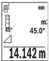
OJwey aAKTaNFAHH KeiH KaKeTI "X" KaWbIKTbIFbIH OJwey HAnKeci HAnKeIep KOnaFbIHda (e) Kepcetinei. "1" KaWbIKTbIFbl MeH "a" 6ypbIbIHbIH OJwey MAnDepi OJwey MAnDepiH (d) KOJaBHDA TpyaBl.
b) Koc xahama 6niktikti eIwey (F cypetih kapaHbi3)
OJnwey Kypanbl Ohbi BepTKaIdbi DeHReiHne KaTaTBiBapnbIK KaWBkTbIKTapdbiKaHaMa eJnweyi MymkiH.
KocKaHama6nIKTKiTeIeIwey cyHKcuaCbIH TaHaHbI3.
Y3bIHbIKtbIeHHei"1"XaHe"2"KaWbIKtbIcTapbIHocblpeTTINIK60BbHwa 0nweH3.
428|Ka3aK
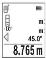
OJwey aKaTaNFaHHaH KeiH KaKeTTi "X" KaBbIKTbIFbIH OJWey HATNXeCi HATNXeIep XoJaFbIHda (e) KepcTeInei. "1", "2" KaBbIKTbIKTapbI MeH "a" 6ypblbIHnIwey MAnHepi OJWey MAnHepiH (d) XoJaFbIHda TpaIbl.
OJnweydiHeri3ri Jka3blkTbIbI (Mbicanbl, OJnwey KypaBihH apTKbl Xneri) 6apnbK eJnwey apekeTTepiHeridien OJnwey aDiciHde bip
kaJa 60anaIbI.
c) KaHama y3bIHdbIKtbl enIwey (G cypetih kapaHbi3)
KaHama y3bIHdbIKtbi eIiwey HkunrcbH TaHaHbI3.
Onwey KypalbHbH i3dienre H onwey Hkyteimeh 6ip 6niktiKte 6onybHa Ke3 XeTKi3iH3.
CodaH Kein H onwey KypalbH Heri3ri Ka3bIKtBkTah Kaibpbl, "1" KaWbIKtBIfbH
y3blDbIKbl OJWeReHde OJWeH3.

OJwey aAKTaIFaHHaH KeiH KaKeTti "X" KaWbIKTbIFbIH OJIwey HATNXeCi HATNXeIep KOnaFBHda (e) KepcetineDi. "1" KaWbIKTbIFbIMeH "a" 6ypblWBHbH eJIwey MAnepi eJIwey MAnepinH (d) KOJaFbIHDa TpyaBl.
Ka6bipfaydaahbH onwey (HCypeTih KapaHbI3)
Ka6bipra aydaHbH enwey 6ipHewe xaIbI 6nIKTI 6oJIe aydaHapdbH KocbHbCbH ecenTey ysiH naIaHaBInaIbI. Kpcetinre HmbCaIaH 6eJIme 6nIKTiri 6ipJe, 6pak L y3bHdbfbl aPtpni 60aTbH 6ipHewe Ka6bipFaHbIH xaIbI aydaHb ecenTeNdi.
Ka6bipraaydaHbIH enwey dyHKnrcbH TaHaHaB13.
H 6bnme 6nikirin y3bHbIKtbi eIwereHne enweHiz. OIwey mHI Jcofapfb IeWey mHi JcNarfbHa Kepctinei. Na3ep KocblraH Kynde kanaDbI.
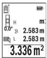
CodaH Kein 6ipihi Ka6bipFaHbH L y3bIHdbfBn HneH3. AyaHbI abTOMaTbI Typde ecentenIn, HtJKepe JOnaFbHda (e) Kepcetinei CoHbI y3bIHbIKbI enwey mHi acTbIHbI enwey mHdepi JOnaFbHda (d) TypaBl. Na3ep Kocblfah 6oNbl Kanadbl.
Ehdi ekihui Ka6bipraHbIH L2 y3bIHdbfbiH oIwei3. OIwey mHi KOnaftHa (d)KepcetinreH eIwey mHi L1 y3bIHdbfbiHa KocblnabI.
Eki y3bIHdbkTBH (opTaHbI eNwey mHi xOJaBHa d) KepCetinreH) KocbIHDbCb caTaNFaH H 6nIKtiHne Ke6eHtinei. KaNbI aydaH mHi hTeHXKeJep XOJaBHa d (e) KepCetinei.
Ke3 KeIreH bacaLx y3bIHbIKTapbH eIweyre 6oana,b, onap aTOMaTT type KocblbIn, H 6niktirine Ke6eintinei. Dypbc aydaHbI ecenTeyin anFbIwapTb - 6ipihwi eIweHren y3bIHbIKTBH (Mbicbl, H 6eIme 6niktiri) 6apnb6enek aydaHnap ysiH 6ipdeBonybl.
TpaccnpeyfHKnncbI (I cypeTIN kapaHb13)
Tpaccnpey cyHKunrcb aHbIKtaIaNfAH y3bIHdbIKtbl (KaWbIKtbIKtbl) eIWeiDi. OcbI y3bIHdbIKtapbl 6eTepre Kewipin, MaTePnAnDbI 6ipDeN eIWeM 6eIikTePiHe KecyRe Hemece KapKacTBk rHnckapToH Ka6bIPanapDbI opHaTyfa 6oNaBl. PeTeyre 6oNaTbIH MNHMaJIbI y3bIHdbIK0,1 M KypaJNb, MaKcMaJIbI y3bIHdbIK 50 M KypaJNb.
Hycay: Tpaccnpney fynkncsbcihda bennireyre deinHri KausbkTBk,dnCnneJe Kepcetinei. AhbiktamalbIK Hkyte eIwey kypaibhJxneri 6onbl Ta6bnMaHdbI. Tpaccnpney fynkncsbcih taHaDaHb3.
Kaeketti 3bIHbIKTbi (6) [+] Hemece (3) [-] TYMecimeH opHaTbIHbI3.
Tpaccnpney yHKnCnBn eIwey tyMecin (5) [bacy apkblbcke kocbl, bactankbly Hkytehen bary anbICTaHb3.
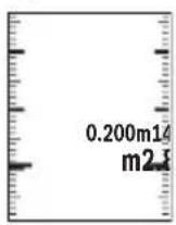
OJnwey Kypanbl y3dkci 6actay HkTecine deinIH KaWbIKtBkTbI eJnei. OHda aHbIKtaIah y3bIHdbkTap MeH aFBIMdkEJIWeMep Kepcetenei. TomeHri Hemece KofapFbI KepcETKI KaKbIHdAn XaTKaH Hemece coHfbI 6enrire deinEH Kbicka KaWbIKtBkTbI KepcTei.
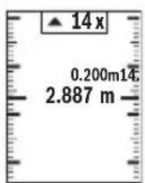
CoJ KaTbIK fakTop 6enrineHReH y3bHdbK HeWe pet XeTiinreH IN Kepcetei. Kacbl TycTI eNwey mHi 6enriney MaKcaTbIHda Y3bHdbKKa KOJ KeTKi3yDi Kepcetei.
Kek tycti eIwey mHi aHbIKtamalbIK MAn DNcNneJeH TBIC 6oHaHaHaKaTbIMaHdi KepceTei.
Eni ci Tienwey/caHdbik deHre
Ehicti onwey/cahdbk dHeHRe yHKnAcbIH TaHaBb3.
Thwey KypaIbI eki Kyi apacbiHa e3repte.i.
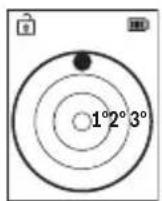
CaHbIK DeHRe HbICaHHbIH rOpH3OHTaIbI HeMeCE BepTKKaIbI 6aFbITanybHa Kbi3MeT eTei (MbICaJIbI, KIP XyFbIIM MaUNHa, CybITKbI W KHe T.6.).
Erep 3° eHicTeH acbIn KeTce, dncnneIe Kbl3bl TycTI wap JkaHaDbI.
430|Ka3aK
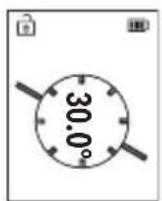
Ehicti eHwe cyHKnucbI KTepeinicti Hemece ehicti eHwe (Mbicbl, catbHbH, TaHbItapdbH, XHa3DbI Kipictipreh Ke3e, Ky6bpnapdbI etki3reH Ke3e JHe T.6.) ywiH KOJaHbIaIbI.
Enicti enwey ywiH herizri kazbiktbk petiHne enwey KypaibHbH, con Xafti naIdaHaBnabbl.
"RepMec" BO, 7 ka6aT
Ten.: +7 (727) 331 31 00
ΦaKc: +7 (727) 2330787
E-Mail: ptka@bosch.com
CepBnctIK Kbl3MeT KepcTeY opTaIbIKTapbl MeH Ka6blNay nyHKTePiH MeKeH-KaBl Typalbl TOnblK XHe 03eKti aKnapaTb Ci3: www.bosch-professional.kz pecMn caTTaH ana aIacbl3
KbI3MET Kepcety optaibikTapbih6acka da MekehkaHapbIH MblHa XepdeH KapaHbI3:
www.bosch-pt.com/serviceaddresses
TacbImaIay
IHTH-nOHdbk aKKymyIaTOpnap Kayinti TayapnapfKaOBbIaNbIH TaanTpFcaN 6OlybI KepeK. PAndanaHysbI aKKymyIaTOpnapdbI KeWeDe KOCbIMwa KyxatapcbI3 TacbImaIaNa anadbl.
Ywihwi tapanTap (Mbicnbl, aye Keiiri Hemece XeHenty Kbi3meti) opaybikka XaHe bEnrineyre KoBinaTbH apHaBbl TaanTapdbI opbIHdaybTnic. Ki6epyre daBihday KeiHnde Kaynti JyKTeprTi TacbMaJday capanWBicbImeH xa6apnacyKepeK.
AkkymyIaTOpdbkopnycbl3akbIMdaIaNfah60nca fanaXi6epin3.AuBik tyicnepepi KENIMdeH3KHe aKKymyIaTOpdbI opamada KO3FaMmaTbIHdAn opaHbI3.KaKeT 60nca, KOCbIMwa yITbIK epexepepi caKaTaHbI3.
Kadere kapaty

OJIwey KypaBih, aKKymnTOpbIH/6atapeenapbIH, OHbIH Xa6DbkTapbI MeH opamacBH KopwafAH opTaHbI KopFaNTbIH pette KeJeE xapaTy opHbHa Tancbipy KaKeT.
OJIwey KypaIapbH JxHe aKKymIaTOpnapbl/6atapeaIapblYKoKbcIHa TAcTaMaHb3!
TekKaHaEOepei yuH:
Eypona 2012/19/EU epexeci 6oBbHwa Japamcb3 eIwey Kypanapbl JHe Eypona 2006/66/EC epexeci 6oBbHwa 3aKbIMdaIraH HeMece ecki aKKymyIaTOp/6atapeenap 6beek XnHaBIn Kdere JkapatblNybl KaKeT.
AkkymyIaTOPnap/6aTapeIaIap:
JIHTHn-NOhBik:
Tacbimay 6bnimHderi, betinderi HcyckaynapbI opbHdaHb3 (kapaHb3 ,Tacbimay" Bef 434) cehcopnbIK nephemepaTaHb3.
Româna
Instruţiuni de siguranta

Service scule electrice
Strada Horia Macelariu Nr. 30-34, sector 1
013937 Bucuresti
www.bosch-pt.com/serviceaddresses
Transport
(a) OtnpaBHa paBHnHa 3a n3MePbAHeTo
(b) CtaTyc Ha CBbp3BaHe

Bluetooth® eakTNBnpaH, Bpb3Ka He n3rpaDeHa

Bluetooth® e aKTHBnpaH, n3rpaDeHa Bp3Ka
(c) HndnKaTOp 3a 6aTepeRyTa
(d) PeDoBe 3a n3MepeHnte cToHOCTH
(e) Pe3a pe3yntata
(f) ΦyHKUЯ 3a n3MepBaHe
(g) Pone 3a bTbHa Hau KaHa
(h) CtaTycha IeHTa
(i) HndkaTOp Ha dncnpe yHKun 3a n3MePbaHe
(j) HndkaTOp Ha dncnner OCHOBn HacptpoKn
(k) HndkaTOp Ha dncnner 3a DoNbHnTeHN HaCTpoK
TexHnueckn daHHN
IocTaeHc/CMHaHaJIHTHeBO-HOHHaakymyLaTopHa6aTepeHn (pHHaJeKHOCT)
IocTaBeteJIHTHeBO-IOHHaTaakymyLatOpHa6atepna(24)(Bx.ΦnA).3aH3BaJdaheHaJIHTHeBO-IOHHaTaakymyLatOpHa6atepna(24)HaTNCHeTeΦHKcnpaHTo(25)H3BaTeJIHTHeBO-IOHHaTaakymyLatOpHa6atepna.
Pa6ota
3apejdahe ha nHTneBO- noHha akymyNatopHa 6aTepe (npHaJnxKHOCT)
Yka3aHne: AkymyNaTopHaTa 6aTePnCe DoCTaBn YacTnHy O3apeHe. 3a DoCTnHaHe Ha nbHata pa6oTOcNOcO6HOCT Ha akymyNaTopHaTa 6aTePn IpeDn PbBTo nON3BaHe 3apeTe akymyNaTopHaTa 6aTePn DOKpaN.
USB 6yKcata 3a cBbP3BaHe Ha USB Ka6eNa (26) N KOHTpOHaT aAMnHua 3a 3apeXdahe ca noJ KanaKa Ha USB 6yKcata (27) Bbpx LyTNHeBO-IOHHata aKymlaTopHa
6aTepe (24) (npHaIeXHocT).OTbOpTe KaNaka Ha USB 6yKcata (27) n 3aTbOpTe USB Ka6eNa (26).
466|BbIrapckn
No BpeMe Ha 3apeXdahe HINdkaunraHa 6atePnTa Ha nCpner MoKe da ce pa3nuaBa OT DeiCTBnteHOTc bctoHne Ha 3apeXdaHe Ha NITNeBO-NOHHata akymyNaTOPHa 6atePnR (24). Korato NITHeBO-NOHHata akymyNaTOPHa 6atePnR (24) e HanbInHO 3apeDeHa, KOHTPOHATA NaMnUka 3a 3apeXdahe CBeTBA B 3eNEHO.
IIO BVPeMe Ha 3apeXdaHeTO KOHTpOHaHaTa NaMnHcKa 3a 3apeXdaHeTO CBETN B XbJITo. YepBeHa KOHTpOHa NaMnHcKa 3a 3apeXdaHeTO CnHAn3npa, Ye HAppeXeHHeTO NIN TOKbT Ha 3apeXdaHe Ca HeNoDxOJaU.
Пускан eкпноатаць
He octabayte ypea Bknouen 6e3 na30p; cnei kaTO npnKnIOuHTe pa6ota, ro H3KIOUBAIte. pyrnn nua MoarTa da 6bDat 3aceneHn OT na3epHnaIbq.
IpeNa3BaTe H3MepBaTeHHn np6op OT OBnXHBAHe n DnpeKTHo nonaHa Ha CbHcEBn Ib4n.
He n3naraTe H3MepBaTeHnHa eKCTpeMHn TempeaTyPi Hn pe3Kn TemnepaTyPi npomeHn. Hanp. He ro octaBnTe npOdbJNKeIHO BpeMe BAOTOMoHn. Pn rOlenm TempeaTyPi pa3NIkOcTaBaIe H3MepBaTeHnT ypei IbpBO da ce Temnepu npEi Da ro BKIOHTe. Pn ekCTpeMHn TempeaTyPi Hn rOlenm TempeaTyPi pa3NIkToHOCTTa Ha H3MepBaTeHn ype MoKe Da ca BNOuHn.
H36yBaTe CnHH ydapn Hnn H3nyckaHe Ha n3MepBaTeHHa HctpymeT. Cnei ydapn Bb3deNCTBnB Bbpxy n3MepBaTeHHa HctpymeT Tp6Ba Da n3BbPWBate npoBepKa Ha TOOHCTTa My, Ppei Da npoBjKte Da ro n3no3BaTe (Bx. ,PiobepKa Ha TOOHCTTa N KaIIbPnpaHe Ha n3MepBaHeTo Ha KaIOh (Bx. qnr. M), CtpaHnca 475) n (Bx. ,PiobepKa Ha TOOHCTTa Ha n3MepBaHeTo Ha pa3ctOHHe", CtpaHnca 476).
N3MepBaTeHNNrT ypeI e cBOpbXeH c 6e3XnUeH HHTepFeIc. Tp8Ba Da ce cna3-BaTEBEHTyAnHOrpaHnueHH, HApP. B CamOnEtNnn 60nHnCn.
BknIOuBaHe n3KnIOuBaHe
-3a BKNIOUBAHe Ha H3MepBaTeHnHa ypei Ha Ia3epa HaTnchete KpaTKoTpauHo 6yToHa 3a H3MepBaHe (5) [ ]
-3a BKNIOUBAHe Ha n3MepBaTeHnna ypei 6e3 na3epa HATNCHEte KpaTkoTpaHObyToHa BKn/IN3Kn/Ha3ad (8)[F
He hacouBaIte na3epHna Ib4 KbM Xopa HnXHBOTn; He rneJaTe cpeuy na-3epHnaB,cbso n OT rOJMo pa3CToHHe.
Pn npBpBOHaunHO BkIIOUBaHe Ha n3MepeBaTeHHy yep ige 6bTe Te NOkaHn da HactPone ppeNoHTaHn e3NK 3a TEKCTOBeTe Ha dncnner.
3a n3KnIOuBaHe Ha n3MePBATeHnHa ypei 3aIpbXte 6yToHa BkN/In3Kn/Ha3aD (8) [ ] HaTNCHaT.
PnH3KJIIOUBaHe Ha H3MePBATeIHHy ypeI HAmpaIITe Ce B NaMetTA CToHOCTN HAcTPOIKITE ce 3ana3BaT.
H3mepBaHe
CneIbpbBTO BKNIOUbaHe H3MePbATEJIHHrT HHCTpyMeHT Ce HaMnpa BpeKIM 3a H3MepBaHcHa IbIXHH. CnE BcAko CNEBaIO BKNIOUbaHe H3MePbATEJIHHrT ypeI ce HaMnpa B NocJeHNO H3N0J3BaHaTa FyHKuHa 3a H3MePbAHe. 3a Dpyra FyHKuHa Ha H3MePbAHe HATNCHEte 6yToHa (2) [Func]. H3sepeTe JKeJaHaTa FyHKuHa 3a H3MePbAHe c 6yToHa (6) [+] nII 6yToHa (3) [-] OT (Bx..FyHKuHa 3a H3MePbAHe", CtpaHua 468). AKTHBHpAte FyHKuHaTa 3a H3MePbAHe c 6yToHa (2) [Func] nII c 6yToHa 3a H3MePbAHe (5)
3a pepepeHTHa paBHHHa Ha n3MepBaHeTo ca HnHn TpHn HacTpoKn (Bx. ,N3bnpaHnHa pepepeHTHa paBHHa (Bx. pHr. B) ", Ctpanuca 467).
Ioppe H3MepBaTeHnHa ypeD IO JeenaHaTa HauaHa TOUka 3a H3MepBaHeTo (Ha np. CteHa).
Yka3aHHe: Ako n3MepBaTeHHnT ypeE bKIIoueH c 6yToHa BKn/IN3Kn/Ha3aI (8) [ ] , HATCHETe 3a KpATKO 6yToHa 3a IN3MepBaHe (5) [ 3a Da BKNIOHTe Ia3epa.
3a cTapTnpaHe Ha n3MepBaHeto HaTnCHeTe 6yToHa (5) [Cnei TOBa Ia3epHnI TbU ce n3KnIOvBa. 3a CneiBaIo n3MepBaHe NOBTOpe Ta3n npOeDypa.
He hacoubaite na3epHHn bqu KbM Xopa nn KHBOTH; He rneadaTe cpeuy na-3epHHn bqu, cbso n OT rOJMAo pa3ctOAHHe.
Yka3aHHe: N3MepeHaTa CToHOC T6NKHOBeHO Ce N0BBA CneD 0,5 S H He NO-KbCHO OT OK.4 s. PpOdbJIxHTenHOCTTa 3aBnCH O T pa3CToRHNTO, CBETNIHHNTc BcOTHOJEHn IOTpaXaTeHNHTe CBOICTBa Ha UeNEBaTaNOBbpXHOCT. CNeI npHKIIIOUBAHe Ha N3MEpBAHeTo Na3epHnTlbCe N3KIIIOUBA aBTOMaTHNoHO.
H36upaHe ha pepepeHTha paBHnHa (Bx. qnr. B)
3a n3MepBaHTo MoKeTe Da n36npaTe MeJy Tprn pa3nHn NaayanHn paBHnH:
-3aHnpaHpHa HmepBaTeHHypeH (Hanp. npnDOnnpaHe do cteHa),
- npednna pb6 ha n3mepBaTeHHn ypei (Hanp. npin n3mepBahe ot pb6a Ha Maca),
- ceHTbpa Ha pe36OBn8 OTBop (14) (Hanp. npn n3MepeBaHe cbc cTaTHB)
3a n3bop ha hauahhata toka hatnche 6ytoHa (7) [Cnei TOBa n3bepe c 6ytoHa 3a n3MepBaHe (5) [A] nn C 6yToHa (2) [Func] Hactpoikata „Pepeentha paBHHa".
CneTOBa n36epete c 6yToHa (6) [+] mN C 6yToHa (3) [-] XeNaHata pepepeHTHa paBHHa. CneBcRAKO BKIOUBAHe Ha n3MePbTeHNn ypeI ppeBapNTHo HAcTpoEHa e NocJeHNO n36paHATA pepepeHTHa paBHnHa.
468|BbIrapckn
MeHIO „HactpoINKn"(Bx.Φnr.C)
3a da Bne3eTe B MeHIO ,HaCtpoNKn" (j), HATnCHete 6yToHa (7) [
I36epeTe c 6yToHa (6) [+] nIn 6yToHa (3) [-] XeNaHata HacTpoiKa n NOTBbPdTe c 6yToHa 3a I3MepBaHe (5) [▲] nIn C 6yToHa (2) [Func].
I36epete JKeHaHata HactpoiKa c 6yToHa (6) [+] nnn 6yToHa (3) [-] JKeHaHata n noTbpeTe c 6yToHa 3a I3MepBaHe (5) [▲] nnn c 6yToHa (2) [Func].
3aДаинэзеTe OT MeHIOTo „OCHOBHn HAcTpOoiKn“, HATNCHeTe 6byToHa BKn/ɪn3Kn/ Ha3aI (8) [ ]
CneHnTe HAcTpoKNaHaJIuHn:
- BkIIOUbaHe n I3KIIIOUbaHe Ha 3ByKObna CnHnA
-Bn6paunBkIouBaHe/ntKJIouBaHe:Be KbcN Bn6paun CnHaHn3npaT 3a yc- neuHO n3MepBaHe,blra Bn6paun CnHaHn3npa 3a rpeuHO n3MepBaHe.
-0cbetneHHeHaDnCnnpe - PexnHa necteHa 6aTepe: BkIouen pexm TohBt N BbpaunrTa ce deakTbnpaH npKocTa Ha dncnpepeynpa. TaKa ce HamaJIBa BpeMeTo Ha paOta Ha 6aTeepra.
- CmHa Ha MepHaTa eHnHa ft/m
-HacTpoiKaHae3nKa - PRO360 -PpBOHaayHNO aKTHBnPaHe e HxkHo. PpeDaBaHeTo Ha daHHe Bb3-MoXHO cAmO cbc CbOTBeHTO pnploKeHne Hn KOMIObPha npoRpaMa. Cne dcmHa Ha 6aTePnTa Tp8Ba n3MePbTeHNrT ype Da ce BKIOuN BeINbK, 3a Da ce CTapTnPa NOBTOpho PRO360. PRO360 MoKe no BcKO BpeMe Da ce DeakTNbPa OTHOBO. DOnbHnTeHa HOpMaun 3a PRO360 ue OKPHe Ta adpec www.pro360.com.
-Инфорmaцязaypeda i
-Фабрчнн HabТpoикn
ФункцииЗаИзмервае
BHHMaBaIte npn BCnUKN eDHHuHn H3MePbAHnHa HnHdNpeKTHOTO onpeIeHHe Ha BnCOuHn OITnpaBHata paBHnHa (Hanp. 3aHnT p6 Ha n3MePbTeHNy ype) da OCTaba He npomeHeha.
B) INHnpekTHo H3MepBaHe Ha IbIiXnHa (BX. qnr. G)
H36epete HndnpeKTHOTOn H3MePBAHe Ha IbIxxHa
BHHMaBaIte H3MepBaTeHnHrT ypeI da e Ha cbuata BnCOUHa, Ha KOaTo e TbpcHeTa KpaHa ToUka Ha H3MepBaHeto. CneI TOBa 3aBbPte Te H3MepBaTeHnHa ypeO kONo OTp paBHata paBHnHa n H3MepeTe pa3CToHnEto "1" no HaunHa, NO KOHTo H3MepBaTe DblKHH.
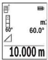
CneI npKluBaHe Ha n3MepBaHTo pe3yntaTbT 3a TbpceHOTo pa3-CTOHNe "X" ce n3PnCBA Ha peDa (e). N3MepeHHTe CTOnHOCTn 3a pa3-CTOHNeTO "1" n bTbna "a" ca n3nncAHn Ha peDoBeTe (d).
H3mepBaHe Ha nnoi Ha cTeHH (Bk. qnr. H)
I3mepbaheTo Ha nlouHa CTeHn CnyxHa onpeJeHHe Ha obua nlou, cyMa OT HAKoKo OTdEInHO n3MepeHn nlouH, Hmaun o6ua BncoUHa. Ha nokaahn npImep Tp6Ba da
472|BbIrapckn
6bnde onpeeneHa oBuaTa nlouHa HRAKoKo CTeHn, KOHTo IMaT eHa N Cbua BnCOUHa Ha NOMEeHHeTo H, HOc pa3NHyIbJxHH L.
CINHcTOnHOCTOTN3MepBaHe NOKa3BaDeiCTBHTeHaTa CToHOCt, aKOpepepeHTHaTa CToHOCTe H3BbH DnCnIeJ.
H3mepBaHe Ha HAKIOH/UNΦpOBA NH6eNa
I36epete I3MepBaHe Ha HAKIOH/UNΦpOBA N6eNa
I3mepBaTeHnHrT ypeIe IpeBkIIOUba aBTOMaTHuHO MeKdy DBe CbCTOHaHn.
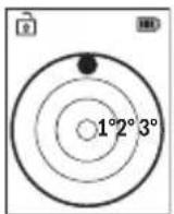
UHPOBATA H6eNa CnyKn 3a npOBepKa Ha XOpN3OHTaHOTo HnBepTnKaIHO IOppaBnBaHe Ha oBeKT (HaNP. MnaJIHa MaunHa, XnaDnHnK nT.H.).
Korato HakoHbT npebuaba 3° ,Ha dncnne CBeTba YepBeHaTa TocKa.
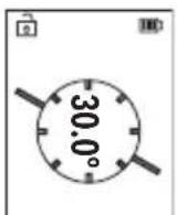
I3MepBaHeTo Ha HAKIOH CnyKu 3a H3MepBaHe Ha bTbN Ha HAKIOHeH NOBbpxHOCTn Hm MncLeHn PpaBn (Ha np. Ha CTbN, npapaneTn, CBOdoBe 3a Me6eHn, pni npekapBaHe Ha TpbN nDp.n.).
KATO OTnpaBHa paBnHa npn n3MepBaHeTo Ha haknoh cnjxN IyBaTa CTpaHa Ha n3MepBaTeHnry ypei.
3anaMeTeHcSTOHocTH
CToHocTtA,pecn.KpaHnrt pe3yIITaT OT BcAKO npNKlIOuHIO H3MePBAHe aBTOMaTHUHO ce 3aHNCBa.
Morat da 6bdaT n3BnKaHn Hau-MHO 30 cToHocTN (n3MepeHN cToHocTN nn KpaHn pe3yntaTn).
H36peTeФyHKUHTa3anaMeTBAHe [
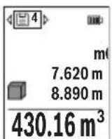
B rohpata qact ha dincnpeer ce noka3ba HomepbT ha 3anameteHa t a ctoHocT,OTdony-camata ctoHocT,a OTnRABO- yHKuYra,Tnp KOaTo e bna onpeDeneHa.
HaTncheTe 6yToHa (6) [+] ,3aJa npEnCTHte HAppeB 3anamTeHInTe CTOnHOCTN.
HaTnchete 6yToHa (3)[-],3aJa npEnHCTHe Ha3aB 3aNaMeTeHNTE
CTOHOCTN.
Hai-ctapata 3anameteHa cToHocT ce HAMpa B no3nua 1 B nAmetTa, a nocneHaTa 3a-nameteHa-Bno3nua 30 (npn 30 3anameteHcSTHOCTn).PpN 3aPiNCBaHe Ha cIeDba- uN cToHocTH Ce H3TpNBa BNHaHn Hai-CTapata 3anameteHa cToHocT.
474|BbIrapckn
H3tpnBaHe Ha cbDbpXaHHeTo Ha naMeTTa
3a n3tpnBaHe Ha OTdEHLa CToHOCHa 3anaMeTBAHe H36epeTe Ta3n CToHOCOT(BK.
3aIamTeHN CToHocTn",CTpaHnca 473).3aN3TpNaBe HATNCHe NpBBO 6yToHa BKn/ n3Kn/Ha3aD (8) [ ] nOTBbPdTe c 6yToHa (2) [Func].
3a n3tpnBaHe Ha qAnoto CbDpKaHne Ha naMeTTa HATncHe 6yToHa (7) [m36epTe cyHKuIra. HATncHe TcNe TOBa 6yToHa (6) [+] nOTBbpTe c 6yToHa (2) [Func].
Cb6npaHe/n3BaXdaHe Ha cToHocTH
H3mepeHHn H3uHcneHH cToHocTH MoRaT da 6bDaT cb6HpAHn Hn H3BaXdaHn.
Cb6npaHe hctOHocTn
CneHnT npImep onncBa cbbnpaHeTo Ha nlou:
YcTaHOBeTe NOBbpxHocTtA CbflaCHO pa3dEn „N3MepBaHe Ha NOBbpxHocTn“ N3MepBaHe Ha PIOU.
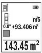
HaTnchHe6byToHa (6) [+].HaIncPnpeCe noka3BAt n3uNCHeHata IIIOUICMBOJIbT ,+".
HaTnchete 6yToHa 3a n3MepBaHe (5) [3a Da cTapTpate dpyro n3MepBaHe Ha nIOu. YcTaHOBeTe NOBbpxHocCTTa cbrIacHO pa3dien ,n3MepBaHe Ha NOBbpxHOCHT " N3MepBaHe Ha nIOu. KorATO npNKIOU H BTOPO To n3MepBaHe, pe3yNTaTbT OT Hero ce noka3Ba Dony Ha nC
nne.3a da nokaxepeeyntaHaTncheTe OTHO6yToHa 3a H3MepBaHe (5) [
Yka3aHHe: PnH3MePbAHe Ha IbJxHa BeDHa Ce NOKa3Ba pe3yIITaTbT.
3a n3n3ahe opekma ha cb6npahe hatachete 6ytoHa (2) [Func].
N3BaXdaHe Ha cToHocTn
3a n3BaJdaHe Ha cToHocTn HATncHete 6yToHa (3)[-].HaunbTa Ha paBota e aHaIOnu.ueH Ha "DobabJe Ha cToHocTn".
N3tpnBaHe Ha N3MepeHH CToHocTH
Upe3 KpaTko HaTnCKaHe Ha 6yToHa BkI/H3Kn/Ha3aI (8) [MOKeTe Da H3TpneTe BB BCnKn cyHKuIN 3a N3MepBaHne NocJeHO yCTaHOBeHATA CTOHOCr. Upe3 MHOKpAHO KpaKoTPaHNO HAToCKaHe Ha 6yToHa BkI/H3Kn/Ha3aI (8) [Ce H3TpNaBt B O6paTHa NocJeOBaTeHIOCT H3MepeHHTe PpeIN TOBa CTOHOCr.
yka3aHna 3a pa6ota
N3mepBaTeHnHrIypeIe cBOpbXeHc 6e3XnHEn HHTepFeHc. Tp6Ba Da ce cna3BaTeEBeHTyaHn OrpaHnueHHa, HApP. B CaMonetn Hn 60nHn.
067n yka3aHna
IbpeHa n3MepBaHe npHemaata nea (15) n OTBopbT 3a n3XoJnna3epeH nbu (16) He Tp6Ba da 6bDat 3akpnuBaHn.
IIO Bpeme Ha n3MepBaHe n3MepBaTeHnHrT ypeH He Tp8Ba Da 6bJe npemecTBaH (C n3KJIoueHne npn peKHM Ha paBota HnpeKbChato n3MepBaHe). 3aTOBA IIO BB3MOxHOCTdoNHPaIte n3MepBaTeHnHryepDo 3dpaBA ONOPHa NOBbpXHOCT.
ΦaKTopn, BnHaeuBbpxy dHaana30Ha Ha H3MepBaHe
Дианаэоньт ha n3Мерваhe 3aBnCn OT CBETПИHHNte yCNOBnI NOtpa3HTeHnata cnocobHOCT Ha NOBbpxHOCTTа,do KOrTo ce MEPn.3aNo-Do6po BnKJaHe Ha Na3ePnHa IbU npi CNIIHa OKoJIHa CBETnHa H3NoI3BaIte OuHnIaTa (20) (He ca BKJIoueHn B OKOMJIeKTOBkA-Ta) INa3ePHaTa ueleBa nIOUka (19) (npHaJnxHOCT) INn 3aceHcTe ueleBaTa NOBbPxHOCT.
He notonBaIte n3MePBeTnHn ypeB BB BOa IIN dpyrTeuHOCTN.
I36bpcBaTe 3aMbpcBaHnraTa C MeKa, IeKo HaNaxHeHa Kbpna. He n3no3BaTe no-CHBaU npenapatn nn pa3TBOpHTeni.
Othacrte ce cneunno KbM npemaaata nea (15) cbc cbto TO BHMaHHe, C KOeTo ce OTHACrTe KbM ouHa nn ObekTnB Ha oToanapat.
Ipn Heo6xOAnMOCT OT peMOHT ppeIOCTaBnTe n3MePbATEHnYpeD B cHaTata (23).
KnneHtcka cnyk6a n KOHCyntaun OTHOCO ynoTpe6ata
CepBn3bT 1e OTROBOpHa Bbnpocnte Bn OTHOCHO peMOHTn IIOdpBXka Ha 3akypeHn ot Bac npOyKT, KaKTo n OTHOCHO pe3epBHN qactn. POKOMNOHEHTN ueptexn INHOpMaun 3a pe3epBHNte qactn 1e OTKpneTe n Ha: www.bosch-pt.com
EkntnoKocyntaun OTHOCNo ynoTe6ata Ha Bosch ue Bn NOMORHe cydoBONCTBne npn Bbnpoc3a HauHte npOdyKTn TExHIne akcecoapn.
MOnI, npN Bbnpocn n npn npBcBaHe Ha pe3epBn qactn BnHaHn NocOuBaTe 10-ncpEHHaKATALOXeH HOpE, n3ncaH Ha Tabekata Ha ypeda.
Былгаря
Robert Bosch SRL
Service scule electric
Strada Horia Macelariu Nr. 30-34, sector 1
013937 Bucuresti, Romania
TeN.: +359(0)700 13667 (Блгарский)
akc: + 40212331313
Email: BoschServiceCenterBG@ro.bosch.com
www.bosch-pt.com/bg/bg/
DpyrncepBn3Hn apecn ue otKpneTe Ha:
www.bosch-pt.com/serviceaddresses
478|BbIrapckn
TpaHcnpTnpaHe
IHTHeBO-IOHHnTe aKymaTOpHbatepHn IOnJexKaT Ha pa3npoe6nte Ha 3aKOHoTaTeNCTBOTO 3a pa6ota c Onacn HpoyKn. AkymaTOpHnTe 6aTeepn Moat da 6bDat TpaHC-nopTupaHn OT nOtpe6nteHa Ny6nHm Mecta 6e3 DoonbHnTeHN pa3peuHtEHn.
ПпТранспортуаре OT Трети CTрани (Нар. пп ВьздушЕТранспор ИИпОЛЗВаHe Na КурперскУслгИ) Има Спецални ИЗИСКВаHA经 KMОпАКOBaHET O NO6O3HaUaBAHET NМ. 3a ZeNTa пп NOДТ罗TOBkaTа Ha NaKeТИраHETо ce KOHcYItpaITe C eKcNepT B CbOT-BetHATA OБlaCT.
I3npaauTe akymyataopn6batepnn cmo aKO KOpnycT nH He e nobpehen. I3oHpaTe OTKpHTN KOHTaKTTH KJIemC IePAnI NeHTN IOnakOBaTe akymyataopnTe batepnn Taka, ye da He MoarTa ca Ce H3MeCTBaT B OnakOBkata cn. Monr, cna3BaTe cbso ndoBnHHTeHN HaunOHANn PpeDnncAHn.
БракуВанe

C orne ona3BaHe Ha OKoHaTc Cpea H3MepBaTeHnry ypei, oBnKHOBeHnTe nn akymyNaTopHn 6aTePn, DOnbHnTeHnHTe npHaJnxKHOCTN n ONAKOKBnTE TpR6Ba Da ce npedeBaT 3a ONO13OTBOPraBaHe Ha cbDbpxKa- uIte Ce B Tx CypOBHH.
He n3xBpIaIe n3MepBaTeHnIte ypeIu aKymyNaTOpHnTe 6aTePn/ 6aTePnIte npn 6ntOBnTe OTnaDbu!
Cama 3a ctpanH ot EC:
Cbflacno eBponecka npekTnBa 2012/19/EC n3mepBaTeHNte ypei, KOHTo He MoarTa da ce non3Bat noBeue, a cbflacno eBponecka npekTnBa 2006/66/EO nobpeHn Hnn H3xa6eHH oBnKHOBEHH nn akymylatopHn batepHn Tp8Ba da ce cbhpat n npedaBa 3a OON3OTBOPRAHe Ha cbIbprkaUHTe Ce B Tx CypOBHH.
AkymylaTopn6aTepn/6aTepn:
JIHTHeBO-NOHHN:
Mona, cna3BaTe yka3aHnTa B pa3dena TpaHcnpTnpaHe (Bx. „TpaHcnpTnpaHe“, CtpaHnca 478).
MaKeDoHcKn
БeЗб endochn HanomeHn

CnTe yNaTCTBa Tpe6a Da ce npOHTaAT Ha da Ce BHMABA Ha HNB, 3a Da moKe 6e36eHNO H 6e3 onaHocT Da pa6oHTe co MEPHnotypei. DOKONky MEPHnotypei He ce KopHCTn cornaCHO npHIOXeHHe IHcTpyKun, MoKe Da CE hapuHn FyHKunjata Ha BRpaDeHte 3aHTTHMexAHN3MN BO MEPHnotypei.He rH
ouTeTyBaJte haneHnHnTe 3a npedynpeyBaIbe. IObPO cyBAJTE TNOBNE YIATCTBA H PEDAETE T3AEHDO CMEPHNOT YPEI.
BHHMaHHe -doKoNky KopnCTHe npyH ypeH 3a noDecyBaBe n paKyBaBe OCBeH OBd He HabeDeHHe Tnn NOnHaKBn NoCTaKN, OBA MoKe Da DoBeDe Do onaCha H3IOXeHOCT Ha 3pauebe.
MepHnotypee Ce nCnpaYBa co 03HaKa 3a npEynpeyBaBe 3a nacepot (O3haeHo Ha npKka3OT Ha MEPHnotypeiHa rpaHnKkata cTpAna).
IOKONky TeKCTOT Ha 03HaKaTAta 3a npedynpeyBaBe 3a nacepot He e ha BaHnot ja3NK, Bp3 Hero 3aneneTe ja HanenHncaTa Ha BaHnot ja3NK nped npBaTa ynotpe6a.
He ro hacouybajte nacepcknot 3pak KOH Nua HnN XHBOTn H hemojte n Bne camnte da rnaTe BO dnpekTHnoTnn pepeKTHpaqKnot nacepckn 3pak. Taka moKe da ra 3acJeNTe nnata, da npen3BnKaTe Heceke nn Da gn OWTte OHTe OHTe.
Iokonky nacepcknot 3paK Docnee do ouHte, BeDaH Tpe6a da rN 3aTBOpHTe na ja TprHete rnaBata od nacepcknot 3paK.
He npabete npomeHn Ha nacepcknoType.
He rH Kopnctete nacepcknte 3aHTTHN OUHa (doonHnTeHa onpema) KaKo 3auTTHN OUHa. Nacepcknte 3aHTTHN OUHa cnykat 3a noOp6po paCno3HaBaHe Ha nacepcknot 3paK; cenaK, Tne He uHTAT od nacepckoto 3pauehe.
He rKopnCTeIacepcknte 3aHTTHN Ounna (DOnONHnTeHa onpeMa) KaKo ouHna 3a coHnce Hn Nk BO COO6paKaJot. Iacepcknte OUnna He daBaat cEnocha UV-3aHTTaNrHaamayBaat npen03HaBaHbeto Ha 60n.
MepHnot ypeI cMee da ce nonpaba caMo od cTpaHa Ha KBaHnΦHKyBaH cTpyeH nepcoHAn I camo co opHrHahnPe3epBHN DeIOBn. CaMo Ha ToJ HauHH Ke 6ndTe cnryPHN BO 6e36eHocTa Ha MEPHnot ypeI.
He rno octabaje deuata da ro kopncat nacepcknot mepen ype3 ha30p. Be3 Hnd3Op, Tne moxe da ce 3acnenat cebecn nn npytnnua.
He pa6oTe co MEPnOT ypeB BO OKONHa Kae NOcTOn ONaCHOCT Od ekCnNo3Hja, Kae HMa 3anaNbN TeuHOCTn, rac Hnn npaunHa. MEPnOTypeD CO3daBa NCKPn, KOH MoKe da ja 3anaNat ppaTaNn napeata.
He ja otBopajte 6atepujata. Noctoon onacnoct od kpaTOK cnoj.
Pn OwTeYBaBe H HenpOnHcHa yNoTpe6a Ha 6aTepnjata Moxe Da H3ne3e naea. Batepnjata Moxe da ce 3anann nn da ekcnnohp. BHece Te CBex Bo3dyx n DOKoIky mHa NobpeHn OndecTe rHa nekap. PapeTa Moxe da rHa npa3Hn DnshHTe NaNTuTa.
Pn norpeuho KopncBe Hn npn OwTeHa 6aTepnja Moxe Da nCTeue 3anaHbA TeuHOcT od 6aTepnjata. N36erHyBajte KOHTAKT co Hea. DOKONky CnyajHo DojTe BO KOHTAKT co TeuHOCTa, NcNnakHeTe CO BODa. DOKONky TeuHOCTa Doje BO KOHTAKT co OUnTe, No6apajTe neKapcka nomou. NCTeueHATA TeuHOcT od 6aTepnjata Moxe Da npedn3BnKa KoxHn npntauHn Hn H3ropeHnU.
Batepnjata Moxe da ce owtte Od octpnte npedMeTH KAKo Ha np. KINHn Hn ODBpyBaH co hAbopeuho Bnnahe. Moxe da doje do BHaTpeueh KpaToK cnoj n 6atepnjata moxe da ce 3anaH, da nyTuH qad, da ekCnNoHpa Hn da ce nperepee.
Heynotpe6eHata 6aTepnja dpxete ja noaneky od kauenapnckn cnojybanKn, KnyueBn, Jene3HN napn, KnnHcN, 3aBPTKN nn DpyrMaH MeTaN ppeMeTN, WTO MOKe Da npedn3BnKaat npemocTyBaBe Ha KOHTaKTNTe. KpaTOK cnoj Mery KOHTaKTNTe Ha 6aTepnjaTa MoKe da npedn3BnKa n3ropeHnui nn Noxap.
Kopnctete ja 6atepnjata camo BO npOn3BOAn OJ npOn3BODHTeNoT. Camo Ha Toj HauHH 6atepnjata ke ce 3aHTTN oJ onaCHO npeontOBapyBaBe.
BatepHnte nonheTe rco nonhaun wTo ce npenopaahn ncknyuHBO od npon3bOndTeNoT. Dokolky nonHaOT 3a KoJ ce Hamehetn oDpehen BnD Ha batepn, ce KopncTH co dpyr hatepn, noctOn onaChocT od noxap.

3aHTte ja 6atepnjata od tonnHa, Ha np. od donroptajno n3noxybahe Ha coueBn 3paun, oran, HeuHCTOTnB, Boda u Blara. Hnky, nocton onacnoct od ekcnno3na j KpatoK cnoj.
BHHMaHHe! PnKopncTeBe Ha MEPHNOT ypeD co Bluetooth MOxE Da HacTaHaT ppeKn Ha dpyrHte ypeN n CnCTeMn, ABHOH N MeuHcNckn anapatn (Ha np. nejcmejkep, anapatunha 3a cnyahe). NcTo Taka He MoXe ueNoCHo da ce NCKnyuMoXHocTa 3a NobpeDa Ha lyre N XHBOTn BO HeNocpeDHa OKoHna. He To KOPNCTe MePNOT ypeD co Bluetooth Bo 6nn3nHa Ha MeuHcNckypeDn,
6eH3HHCKn Nymn, Xemnckn ypeu, 6bnaCTn CO onaCHOCT OJ EKCnno3Ha n BO 6n3Ha Ha MmHcKn nonHb. He ro KopncTe MePNOT ype d Co Bluetooth BO abHOH. H36erHyBaJte Donroptaja Ynotpe6a Bo DnpeKTHa 6n3Ha Ha tenoto.
BmTeTeToIINHym-jOHCKNt6aTePnCKn naket (24) (BnDn CnKa A).
3a da ro n3BaIHTe IHTyM-jOHCKNOT 6aTePnCKn naKeT (24) npHTnCHte Ro MExAHn3MOT 3a 3aKnUyBaBe (25) n 3BaTeTe ro nHTyM-jOHCKNOT 6aTePnCKn naKeT.
Ynotpe6a
Ponhebe ha nHTym-jOHcKnOT 6aTepcKn naket (onpema)
Hanomeha: BaTepnjata ce nCnpaUyBa denymHO HanonHeta. 3a da 06e36eHnte MaKcImaHekanauHT ha 6atepnjata, nped npBata ynoTpe6a HanonHete ja cenuoHo.
USB-OTBOPOT 3a NOBp3yBaHe Ha USB-Ka6en (26) n KOHTpOHaT a CnJaIuHka 3a noJIHeBe MoKe da rH hajTe NoJ NOKNoeOTo Ha USB-OTBOPOT (27) Ha NITnYM-JoHCKNt O BATEPnCKn NaKet (24) (onpeMa). OTBopTe ro NOKNoeOTo Ha USB-OTBOPOT (27) n Nobp3eTe ro USB-Ka6enot (26).
3a BpeMe Ha npoecocT Ha nonHebe, npka3OT 3a 6aTeepn MoKe Da OTcAnyBa od
akTyenHata cocto6a Ha HanoHETocT Ha nHTym-jOHCKNt 6aTePnCKn NaKeT (24).
Dokonky nHTym-jOHCKNt 6aTePnCKn NaKeT (24) e ceNoCHO HANOHNet, KOHTponHaTa
cnjannka 3a nonHebe CBeTH 3eNeHO.
3a BpeMe Ha nonHeBeTo, KOHTpOHaTa cnJaHnUka 3a nonHeBe CBETn KcITo. LpBeHa KOHTpOHa cnJaHnUka 3a nonHeBe CnHaHn3npa DeKa HApOHr Ha nnonHeBe nn cTpyjata 3a nonHeBe ce HecooDBeTHN.
CTabaHe Bo ynotpe6a
He ro octabajte BknyeHnOT Mepeh ype63 nAa3Op HncknyeTe ro no ynoTpe6ata. Dpyrnte Inuca MoKe da ce 3aclenat od naacepcknT 3paK.
3aHTTeTe ro MepHnot ypeI od Bnara n dnpEeKTHO n3noKyBaHe Ha COHueBn 3paI.
He ro n3noxybajte MEPnOT ypeHa ekctpemHn TemnepaTypn Hn TemnepaTyphN ocunauu. Ha np. He ro octabajTe dolro BpeMe BO aBTOMoHnOT. Ppr rolemn TemnepaTyPhN ocunauu, octabete ro MEPnOT ypeD npBO da ce
aknmaTn3npa, nped da ro ctabte BO ynoTppe6a. Pn ekctpemHn TemnepaTyPi nn TemnepaTyPhN OCuHaau, npeun3HOCTa Ha MEPnOT ypeD MoKe da Ce Hapywn.
H36erHybajte ydapn n npebpTyBaHa MePHnoT ype. IIO cnHNn HADBopeuHN BnjuHnja Ha MEPNoT ype, nped Da npoDOnJXte co pa6Ota, cekoraw N3BpyBajTe npOBepKa Ha ToUHOCTa (BnDn ,PiobepKa Ha ToUHOCTa N KaIIb6PnpaHe Ha N3MepeHnte KocHHn (BnDn CnKaM) ", CtpaHnca 497) n (BnDn ,PiobepKa Ha ToUHOCTa Ha MepeBeTo Ha pactoJaHne", CtpaHnca 497).
MepHnot ypeE onpemEn co 6e3xHueH HHTeppejc. Tpe6a da ce BHHMaBa Ha loKaHNHe OnepaTHBHN OrpaHHyBaHa, Ha np. Bo aBHOH Hn BOnHn.
BknyyBaBe/ncknyyBaBe
-3a BknyyBaIbe Ha MEPHnot ypeN I nacepOT npHTNCHeTe KpaTKO Ha MEPHOTo KOJIe (5) [A
-3a BknyyBaBe Ha MepHnoT ypeI 6e3 Iacep, npHTncHeTe KpaTKo Ha KOJIyeTo 3a BKnyyBaBe/HCKnyyBaBe/Ha3aI (8) [B
He ro hacouybajTe 3paKOT CBETnHa KOH nHa cHa HN XNBOTn He noIeHyBaJTe dIpeKTHO BO Hero,dyprn HN OD rOleMa oDdaneueHoCT.
Pn npBTO BknyBaBe Ha MepHnot ype, od Bac ce 6apa Da ro nocTabte BaHnot npetnoHTah ja3NK 3a TeKCTOBNTe Ha ekpaHot.
3a NcknyuBaBe Ha MepHnot ypeI dpKteTe I npITnCHato KOnyeTo 3a BknyuBaBe/ NcknyuBaBe/Ha3aI (8) [ ]
Pn NcKnyBaIbe Ha MepHnot ypei, BO MemOpjata octaHyBaat 3aCyBaHn BpeHocHTe n NOCTaBKInTe Ha ypeIoT.
PpoecHaMepebe
IIO npBOTO BknyBaHBe, MEPnnot ypeE BO fynKunja Ha doJnxHcKO mepHe. Iocekoe IOHaTAMoUHBO BknyBaHBe, MEPnnot ypeE BO nOcneHata KopncTeHa MEPHa fynKUnja.3a npyra MEPHa fynKUnja npTnchete Ha konueto (2) [Func].N3bepete ja cakaHata MEPHa fynKUnja co konueto (6) [+] nIn KOnueto (3)[-] (BnDn „Mepn fynKUn",CTpaHnua 490).AKnBnpaJte ja MEPHaTa fynKUnja co konueto (2) [Func] nInco MePHOTOKONue (5)[
3a peΦpeHTHOTo HnBO Ha MepeHBeTo DoCTaHn Ce Tpr NocTaBKn (BnDn,In36HpAbe Ha peΦepeHTHO HnBO (BnDn Cnka B)”, CtpaHnca 489).
IocTabete ro MEPHnOT ypeHa ha cakaHaTcTapTHa TouKa Ha MepeHe (Ha np. Snd).
HaNoMeHa: aKO MEPHNOt ypeI CE BknyuN CO KOnueTo 3a BknyuYBaHe/ncknyuYBaHe/ Ha3aI (8) [ ] KpaTko npHTnCHeTe Ha MEPHOTo KOne (5) [ ] 3a Da rO BknyuInTe NacepOT.
3a akTHBnpaHBe Ha MepeHeTo, npHTncHeTe KpATKO Ha MepHO To Konue (5) [Anotoa IacepcknoT 3paK Ke ce NCKnyu. 3a npyro MepeHe nobTOpeTe ja OBaa noCTanka.
He ro hacouybajTe 3paKOT cBeTnHa KOH nHa a HnN XHBOTn He noIeHybajTe dIpeKTHO BO Hero,dypn Hn OD rOleMa OdAnaeYeHocT.
Hanomeha:Boo6nuaeHo,ImMepeHaTaBpeHocTe Ce noJaByBa BO pOK od 0,5 s,a HajdouHa nO okony 4 s.BpeMetpaeheto Ha MepeHeTo 3aBncn od pactoJahneTo, CBeTIOCHNte ycNOBn H peFNeKTHpaUKN CBOjCTBa Ha CEHNrA T NOBpUHHa. ITO 3aBpyBaHbe Ha MepeHbTo, NacepCKNt 3paK ABTomATcKn Ke ce NCKIyH.
H36upahe ha pepepeHTHO HnBO (BnDn cInka B)
3a MepeheTo MoKe Da n36peTe Tpr pa3nHn pepepeHTn HnBOa:
-3aENpa6HaMepHnotypei(Ha np.npniNoCTaByBaIbeHaSnIOBn),
- npedeH pa6 Ha MepHnOT ypei (Ha np. npn MpeHe, noHyBajKn oJ eH pa6 Ha maca),
- cpeiHa Ha HABoJOT (14) (Ha np. 3a MepeHa co CtaTnB)
3a n36op Ha pepepeHTHO HNBO, npHtncHeTe ro KOnyeTo (7) [Ptoa, n36epeTe ja NOCTaBkata „pepepeHTHO HNBO" CO MEPHO TO KOnye (5) [A] INn CO KOnyeTo (2) [Func].
Itoa, n36peTe ro cakaHOTo pepepeHTHO HnBO CO KOnueTo (6) [+] nIc co KOnueTo (3) [-]. IIO ceKoe BkIyUbaHe Ha MePHNoT ypeI, IpTeXoJHO e NocTaBeHO NocJeHOTO n36paHO pepepeHTHO HnBO.
MeHn ,NocTaBKn" (BnHn cInka C)
3aДаВлeЗTe BO MeHTo „ПocTаВКи" (j), npHTnCHeTe ro KOnuTeTo (7) [
Co konchyTo (6) [+] nnn konyeto (3) [-] n3bepete ja cakaHata noCTaBka n NOTBPDeTe ja co MEPHOTo KOyHe (5) [▲] nnn CO konyeto (2) [Func].
I36epete ja cakaHaT a noCTaBka co KOnyeTo (6) [+] nnn KOnyeTo (3) [-] nnotbpdeTe ja CO MEPHOTo KOnue (5) [▲] nnn Co KOnyeTo (2) [Func].
3a da ro hanyuTHTe MeHnTo ,PiocTaBKn , KpaTKO npITNCHeTe ro KonueTo 3a BknyyBaHe/ NCKnyyBaHe/Ha3ad (8) [ ]
OCTaHnCe CNeHnTe NOCTaBKn:

-BknyyBaHbe/ncknyyBaHbe Ha ToHOT
-Bn6paunja BknyuBaHe/ncknyuBaHe:KpaTKn Bn6paunn CnHaJI3npaat YcneUHO MepeHe;eHa KpaTka Bn6paunJa CnHaJI3npa HeyCneUHO MepeHe.
-OCBETnyBaHBeHaekpaHOT
490 MaKeDoHcKn
- Pexm 3a 3aTeHa ha 6atepnn: nBknyeH pexm 3a 3aTeHa ha 6atepnn, ToHr Bn6paunjata ce deakTbnpaaT noCBetneHocTa Ha ekpaHot ce hamanyBa. Co Toa ce npoOnJyBa BpeMeTpaeHeto Ha paBoTeHe Ha 6atepnjata.
-MeHyBaHbHa MepHaTa eINHnua ft/m
-ПодecуBaHeHa ja3NKOT - PRO360 :rope6ho e npBO aKTHBnpahe. IpeHOCOT ha noaTOUe moXeH cAmO co cooDBeTHata anIIkaunja nnco nporpama 3a KOMnyTep. IopomeHa Ha 6aTePN, MEPHnot ypeD mopa nOBtOpHO da ce BkIyUn 3a PRO360 NOBtOpHO da CTapTyBa. PRO360 MOKe BO cekoe BpeMe da ce deakTbHpa. DOnONHHTeHN HnΦopMaun 3a PRO360 MOKe da hajTe IOJ www.pro360.com.
-нфорmaци 3a урет oI
-Фабрчкп поставки
MepHHyHKcH
HnpeKTHo MepeBe Ha paTojaHnja
3a HnDnpeKTHo MepeHe Ha pactoJahJa, Ha pacnoJaraBe BV Ce TpH MepHn FyHKun, CO KOn MoKe Da ce CoonuTat pa3nUHN Tpacn.
HnDnpeKTHOTMepeHeHa pactojaHna cnyKn 3a coonWtYbaHe Ha pactojaHna, KOH He TpeBa DnpeKTHO Da ce n3MepaT, BndejKn HMa npeeKN BO TEkOT Ha 3paKOT HnH HeMa CEHLNa NOBpHnHa KaKO pePfKeKTop Ha pacNoIarHe. OBaa MEPHa NoCTanKa Moze Da ca epnmeHc mo Bo BErTKaJIeH npabeU. Cekoe OTCTanyBaHe BO XOpN3OHTaIeH npabeU BOHN KOH MEPHI rpeShK.
Hanomeha: INdneKTHOTMepeHe Ha pactoJHja e cekoraI NOTOUHO Ond npeKTHOT MepeHe Ha pactoJHja. Bo 3aBnCHocT oN npImeHa, MepHnte rpeKm MoKe da ce IORoJIeMn Ond npeKTHOT MepeHe Ha pactoJHja. 3a NIObOpyBaHe Ha MepHaTa TOuHOCT ppeopayBaMe KOpNCteHe Ha CTaTIN (ONpema).
Pomey noeHneHnTe MepeHa, nacepckno3paK ocTaHyBa BklyueH.
a) INHINpeKTHo MepeHe Ha BnCnHa (BnDn CnKa E)
H36peTe HnDnpeKTHo MepeHe Ha BnCnHn
BHHMaBajTe Ha Toa, MepHnot ypeJa e Ha NCTa BnCHHa KaKo IdoJHaT a MePa TOnKa. Iotoa Habanete rO MepHnot ypeI OKOly pepepeHTHO TnBO H3MepeTe ja Tpacata KAKO KAJ MepHe Ha DOJXHHata,1" (Ha ekpaHOT e npKkaHa KaKO uPBeHa JINHja).
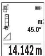
IIO 3aBpyBaHbE Ha MepeHbTo, Ke Ce npKkKe pe3yntaTOT 3a 6apaHaTa Tpaca ,X" BO peoT co pe3yntaT (e). IV3MepeHnTe BpeHocTH 3a Tpacata ,1" N aOJot ,a" CTOjat BO peoOBHTe CO IV3MepeHn BpeHocTH (d).
b)Дбоьно Индпектно Мереbbe Ha BnCnHa (BnDn CnKa F)
MepHnOT ypeI MoKe Ia rN H3MePn DnpeKTHO CNTe Tpacn, KOuTTo neKaT Ha BepTKaJIHOTO HnBO Ha MEPHnOT ypeI.
I36epete IbojHo HndpeKTHo MepeHe Ha BnCHN
I3mepete nTpacnte,,1"n,,2"kako npu mepheHa doJxHH, no OBOj peoocneid.
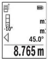
IIO 3aBpyBaHBe Ha MepeHbeto, Ke ce npkaKe pe3yntaTOT 3a 6apaHaTa Tpaca, X" BO peoT co pe3yntaT (e). N3MepeHnTe BpeHocTH 3a TpaCHTe,1",2" H aroJOT, a" CTOjat BO peDObHTe CO N3MepeHn BpeHocTH (d).
BHHMaBajTe Ha Toa, pepepeHTHO HnBO Ha MepeHbeto (Ha np. 3aHnot pa6 Ha MEPnOT ypei) Da cTOn TOUHO Ha nCTOTO MecTo npN
CHTe POeINHeuHMepeHa 3a BpeMe Ha MePHNOT IpoUcE.
c) INHnpeKTHo MepeHe Ha donJxHa (BnIcnka G)
I36epete HndnpeKTHo MepeHe Ha donxHH
BHHMaBaJte Ha Toa, MepHnot ypeI da e Ha HCTa BnCnHa KaKo N 6apaHaTa MEPHa TOUka.
Itoa Habanete ro MEPnnot ypeo OKony pepepeHTHOTo HnBO n3MepTe ja Tpacata,1" Kako kaj MepeHe Ha dOJxHnHa.
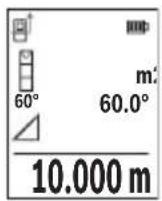
IIO 3aBpyBaHBe Ha MepeHbeto, Ke ce npkaKe pe3yntaTOT 3a 6apahata Tpaca ,X" BO peoT CO pe3yNTAT (e). N3MepeHnte BpeHocTH 3a Tpacata ,1" n aOJot ,a" CTojaT BO peoBHTe CO N3MepeHn BpeHocTH (d).
Mepebe ha sndn noBpuHH (BnH cnka H)
MepebeTo Ha sHdHn NOBpHHn clyxHa da ce do6ne 36np Ha nobeKe noeHNHeuHn NOBpHHn co 3aeHNuKa BncnHa. Ha npimepoT co cNka Tpe6a Da ce odpeHn BKyHnTa NOBpHHa Ha nobeKe SIOBn, KOHMaat HCTa BNCnHa Ha npocTopoT H, HO pa3nHn DOJKNH L.
I36epTe MepeHBe Ha sNHN IOBpHnH
I3MepeTe ja BnCnHaTa Ha npocTopoT H kaKo npH DoJxHcKO MepeBe. I3MepeHaTa BpeHOCt Ke ce npKaKe BO rOpHNot peH Na I3MepeHbBpeHocTH. Iacepot octaHyBa BKnyueH.
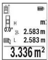
Itoa n3mepete ja doJxHnHaTa LHa npBnOT sID. NobpHnHaTa aBTOMatcKn Ke ce npecmeta HKe ce npkaKe BO peDTo CO pe3yntat (e).IocneHaTaN3MepeHa BpeHocHT Ha doJxHnCA TOn BO doJHnOte d co n3MepeHn BpeHocTn (d).Iacepot octaHyBa BKlyueH. Cera n3mepete ja doJxHnHaTa LHa BtopnoT sID. PnpKaXHaTa IoeHNHeuHa BpeHocT Bo peDTo HA n3MepeHn BpeHocT (d) ce
IdoaBaHa IOnJxHnHaTla 36npOT OndBete DoJxHH (pnpKaJaHa BO cpeHNOT peCo H3MepeHn BpeHocTH (d)) ce MHOxN CO 3auyBaHaTa BncnHa H. BkynHaTa BpeHocT Ha NOBpUnHata Ke ce npKaKe BO peoT co pe3yntaTn (e).
494 MaKeDoHcKn
Mоже дa МерпгЕ Должини NO кениь Lx, Tne abTomatckи Ke ce DoJaTa N Ke ce NOMHOKAT CO BHCINHATA H. YcnoB 3a ToUHa Ппсметka Ha NOBpshHnTe e, npBaTaИЗмeper� Должини (BO пимерOT BHCINHata Ha npocToPOT H) Da e ИдentTuHa 3a CHTeДелOBN OД NOBpshHnTe.
Kako pepepeHTHO HnBO Ha MepebeTo Ha KocHH CnykN IeBaTa CTpaHa Ha MepHnot ypeI.
PnkaHa 3auyBaHaTa BpeHocT
BpeHnOCTa Ond. KpajHnOT pe3yIITaT Ha ceKoe 3aBpseHo MepeHe aBTOMaTcKn Ke ce 3auyBa.
Mоже да ce noВикаat MaKсИмуm 30 ВрEDHOCTH (Измерен ВрEDHOCTH Ип КраJV pe3yntaTn).
I36peTe ja cyHKunjata Ha 3auyByBaHe [
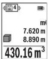
Tope Ha ekpaHot Ke ce npikakke 6pojot Ha MemopupaHaTa BpeHocT, Oany OndHocHata MemopupaHa BpeHocT IN IeBO OndHocHata MepHata cyHKunja.
PnTncHe ro konueTo (6) [+] 3a da npenctyBaTe HanapeD Hn3 3aUyBaHInTe BpeDHOCTN.
PnHTncHeTe KOuHTo (3)[-]3a Da npEnNCTyBaTe HaHa3aH Hn3
Ten./daKc:02/2467610
Mo6.:070595888
Д.П.T.Y“POJKA"
JAnu NykpOBcKn 66;T.LA BToKOMaHaJa IokaI 69
1000 Ckonje
E-nowta: servisrojka@yahoo.com
TeN: +389 2 3174-303
Mo6: +389 70 388-520, -530
DOnonHHTeHH aApceHa cepBnCH MoKe Da HajTe NoI:
www.bosch-pt.com/serviceaddresses
TpaHcnopt
IHTyM-jOHCKNTe 6aTePN NOpJExKaT Ha 6apaBaTa Ha 3aKoHOT 3a ONaCH MaTePN.
BaTePnIte MoKe Ia Ce TpaHcnpTnPaat cAmO oN CTpaHa Ha KOpncnKOT, 6e3 noTppe6a OdoNoJIHnTeHn KBaIInΦnKauzn.
Ipi npenoc Ha nctte od ctpaHa Ha TpeTn Iuca (Ha np. Bo3dyweH TpaHCnpTnnn 1neiunja) HeonxoJHO e da ce BnHmaba Ha CneuiJaHnTe HanomeHn Ha am6anakata H O3NaKHe. Bo TakOB cnuyaj, npn noDrotOBkata Ha npaTKata Mopa da ce nobika ekcnept 3a onacn cyntaHn.
TpaHcnpHpajTe r6batepHnTe cAmOdoKoNky KyKnWTeTo e HeoWTeTeHo.3aIeneTe rnoBopeHnTe KOHTaKNu CnakyBaJTe ja 6atepnjata Ha ToJ HauHH To Hema Da Ce DBrXk BO aM6aJxata. Be MoHmE BHMMaBajTe Ha eBeHTyaHnTe DoONHnTeHN HaunOHnHn npOnncn.
OtctpaHyBaBe

Mepnte ypei, akymnatopnte/batepnte, onpeMaT a mbaJaxnte TpeBa da ce otctpaHt Ha ekONOuKn npHaatnB haunH.
Bosch Power Tools 1609 92A 4ZJ|(14.10.2020)
500 | Srpski
He rH pIajTe mepHnTe ypeu n 6aTeepHnTe BO DOMaunHaTa KaHTa 3a ry6pe!
Cama 3a 3emjnte oEY:
Cnopee ebponckata npekntba 2012/19/EU mepnTe ypei uTO ce BOH ynoTpe6a H depeKTHTe nn NCKOpncTeHNTe 6atepn Cnopei dnepeKTHBaTa 2006/66/EC mopa OndenHO da ce cobepa t na ce peuKnnpaat 3a noBtOpa ynoTpe6a.
AkymynaTopcn 6aTeepn/6aTeepn:
JInThym-jOHcKn:
Be monime BHHMaBajTe Ha HAnomeHnte BO denot TpaHcnpT (BnIn „TpaHcnpT", CtpaHnca 499).
Srpski
www.bosch-pt.com/serviceaddresses
Transport
Litijum-jonski akumulatori podležu propisima koji važe za opasne materije. Korisnik moze transportovati akumulatore na drumu bez drugih pakovanja.
Kod slanja preko trecih lica (npr. vazdušnim transportom ili špedicijom) mora se obratiti pažnja na posebne zahteve u pogledu pakovanja i označavanja. Tada se kod pripreme paketa za slanje mora pozvati strucnjak za opasne materije.
Akumulatorske baterije šaljite samo akо kucište nije osteceno. Odlepite otvorene kontakte i upakujte akumulatorsku bateriju tak, da se nePokrece u paketu. Molimo da obratite pažnju na eventualne dalje nationalne propise.
Uklanjanje dubreta

Merne alate, akumulatore/baterije, pribor i pakovanja treba predat na reciklažu koja je u skladu sa zašitomŽivotne sredine.
Merne alate i akumulatore/baterije nemojte bacati u kućni OTPad!
Samo za EU-zemlje:
Prema evropskoj direktivi 2012/19/EU merni alati koji se više ne mogu koristiti, a prema evropskoj direktivi 2006/66/EC akumulatorske baterije/baterije koje su u kvaru ili
520 | Slovenscina
astrose nemoraju se odvojenosakupljati i uključiti u reciklažu koja odgovara zaštičovekove sredine.
Akumulatori/baterije:
Li-jon:
Molimo da obratite pažnju na napomene u odomjku Transport (videti „Transport“,
Strana 519).
Slovenscina
Varnostna opozorila

www.bosch-pt.com/serviceaddresses
Transport
www.bosch-pt.com/serviceaddresses
Transport
Bluetooth® interfeiss
Datparsutisana uz citamiekartam
Mérinstruments ir aprikots ar Bluetooth® moduli, kas ar Bluetooth® interfeisa palidzibu nodrosina dati parsutisanu uz noteiktam mobilajam gala iericem (piemeram, uz viedtalruni vai plansetdatoru).
Informaciju par sistemas limena prieksnoteikumiem, kas nepieciesami Bluetooth® savienojuma veidosanai, var atrast Bosch interneta vietne ar adresi www.bosch-pt.com.
Darbs ar stativu (papildiederums)
Stativs ir jalieto jo ipasi tad, kad mera lielaku attalumu. Uzlieciet merinstrumenta 1 / 4" vitni (14) uz stativa (21) vai uz tirdzniecibaa pieejama fotoparata stativa atrinomainamas plaksnes. Stingri pieskruejiet merinstrumentu ar atrinomainamas plaksnes stiprino so skruvi.
lestatiet nulles limeni, lui meritiu uz stativa. (skatit „Nulles limena atlase (skatiet attelu B)“, Lappuse 589).
Jostas klipsis (piederums) (skatiet attelu N)
Ar jostas klipsi (17) merinstrumentu var erti piestiprinat pie jostas.
Klumes zinojums
www.bosch-pt.com/serviceaddresses
Transportesana
Litija-jonu akumulatoriem ir piemerojamas prasibas, ko nosaka likumdošana par bistamo kravu transportësani. Lietotäjs var transportet akumulatorus ielu transporte plūsmā bez papildu nosacijumiem.
600 | Lietuvi k.
Parsutot tos ar treso personu starpniecibu (piemeram, ar gaisa transporte vai citu transporte agenturu starpniecibu), jaievero ipaasi sutijuma iesainosanas un markesanas noteikumi. Tapec sutijumu sagatavoisanas laikā japieaicina bistamo kravu parvadāsanas specialists.
Parsutiet akumulatoru tikai tad, ja ta korpuss nav bojats. Aizlimejet valejos akumulatora kontaktus un iesainojiet akumulatoru ta, lai tas iesainojuma neparvietotos. Ludzam ieverot ari ar akumulatoru parsutisanu saistitos nacionalos noteikumus, ja tadi pastav.
Atbrivosanas no nolietotajiem izstradajumiem

Nolietotie merinstrumenti, to akumulatori vai baterijas, piederumi un iesainojuma materiali japaklauj或其他izejai pärstradei apkartejai videi nekaitigā veidā.
Neizmetiet merinstrumentu un ta akumulatorus vai baterijas sadzives atkritumu tvertné!
Tikai EK valstim.
www.bosch-pt.com/serviceaddresses
Transportavimas
Licio jonu akumulatoriams taikomos pavojingu kroviniu gabenim reglamentuojanciu jstatymu nuostatos. Naudotojui akumulatorius gabenti kelais leidziama be jokiu apribojmu.
Jei siunti pasitelkiami tretieji asmenys (pvz., oro transports, ekspedijavimo jmoné), butina atsižvelgi j pakuotei ir zenklinimui taikomus ypatingus reikalavimus. Butina, kad rengiant siunta dalyvautu pavojingu kroviniu gabenimo specialistas.
aI aai I aai I aai I aai I aai I aai I aai I aai I aai I aai I aai I aai I aai I aai I aai I aai I aai I aai I aai I aai I aai I aai I aai I aai I aai I aai I aai I aai I aai I aai I aai I aai I aai I aai I
jll jie jae jaoe baoa J
aJI 1bEgi aaaal jalgi
pJjJI j0 jEgj 20 pJJI J0
J 1000000000000000000000000000000000000000000000000000


D Bluetooth aiaa bgsjg jll ssc 1sic!ssal gaaiaaagaae aai g aas gaaa aas yaaa aaa aaa aaa aaa aaa aaa aaa aaa aaa aaa aaa aaa aaa aaa aaa aaa aaa aaa aaa aaa aaa aaa aaa aaa aaa aaa aaa aaa aaa aaa aaa aaa aaa aaa aaa aaa aaa aaa aaa aaa aaa aaa aaa aaa aaa aaa aaa aaa aaa aaa aaaa aa aa aa aa aa aa aa aa aa aa aa aa aa aa aa aa aa aa aa aa aa aa aa aa aa aa aa aa aa aa aa aa aa aa aa aa aa aa aa aa aa aa aa aa aa aa aa aa aa aa aa aa aa aa aa aa aa aa aa aa aa aa aa aa aa aa aa aa aa aa aa aa aa aa aa aa aa aa aa aa aa aa aa aa aa aa aa aa aa aa aa aa aa aa ae
GLM50-27CGGLM50-27C
jjuU L
| 635,000 gaji > 1 lla | 515,000 gaji > 1 lla | jlll jlll |
| b1g | b1g | |
| äglj) lla lla rla lla lla lla lla lla lla lla lla lla lla lla lla lla lla lla lla lla lla lla lla lla lla lla lla lla lla lla lla lla lla lla lla lla lla lla lla lla lla lla lla lla lla lla lla lla lla lla lla lla lla | äglj) lla lla rla lla lla lla lla lla lla lla lla lla lla lla lla lla lla lla lla lla lla lla lla lla lla lla lla lla lla lla lla lla lla lla lla lla lla lla lla lla lla lla lla lla lla lla lla | |
| äül20 | äül20 | - |
| (G G G G G G G G G G G G G G G G G G G G G G G G G G G G G G G G G G G G G G G G G G G G G G G G G G G C G G G G G G G G G G G G G G G G G G G G G G G G G G G G G G G G G G G G G G G G G G G G G G G G G c c c c c c c c c c c c c c c c c c c c c c c c c c c c c c c c c c c c c c c c c c c c c c c c c c C C C C C C C C C C C C C C C C C C C C C C C C C C C C C C C C C C C C C C C C C C C C C C C C C C c c c c c c c c c c c c c c c c c c c c c c c c c c c c c c c c c c c c c c c c c c c c c c c c c G G G G G G G G G G G G G G G G G G G G G G G G G G G G G G G G G G G G G G G G G G G G G G G G G g g g g g g g g g g g g g g g g g g g g g g g g g g g g g g g g g g g g g g g g g g g g g g g g g g c c c c c c c c c c c c c c c c c c c c c c c c c c c c c c c c c c c c c c c c c c c c c c c c c e e e e e e e e e e e e e e e e e e e e e e e e e e e e e e e e e e e e e e e e e e e e e e e e e e c c c c c c c c c c c c c c c c c c c c c c c c c c c c c c c c c c c c c c c c c c c c c c c c c g g g g g g g g g g g g g g g g g g g g g g g g g g g g g g g g g g g g g g g g g g g g g g g g g G G G G G G G G G G G G G G G G G G G G G G G G G G G G G G G G G G G G G G G G G G G G G G G G G e e e e e e e e e e e e e e e e e e e e e e e e e e e e e e e e e e e e e e e e e e e e e e e e e C C C C C C C C C C C C C C C C C C C C C C C C C C C C C C C C C C C C C C C C C C C C C C C C C G G G G G G G G G G G G G G G G G G G G G G G G G G G G G G G G G G G G G G G G G G G G G G G G C C C C C C C C C C C C C C C C C C C C C C C C C C C C C C C C C C C C C C C C C C C C C C C C C e e e e e e e e e e e e e e e e e e e e e e e e e e e e e e e e e e e e e e e e e e e e e e e e e EJL JI LJL JI LJL JI LJL JI LJL JI LJL JI LJL JI LJL JI LJL JI LJL JI LJL JI LJL JI LJL JI LJL JI LJL JI LJL JI LJL JI LJL JI LJL JI LJL JI LJL JI I JI LJL JI LJL JI LJL JI LJL JI LJL JI LJL JI LJL JI LJL JI LJL JI LJL JI LJL JI LJL JI LJL JI LJL JI LJL JI LJL JI LJL JI LJL JI LJL JI LJ L JI LJ L JI LJ L JI LJ L JI LJ L JI LJ L JI LJ L JI LJ L JI LJ L JI LJ L JI LJ L JI LJ L JI LJ L JI LJ L JI LJ L JI LJ L JI LJ L JI LJ L JI LJ L JI LJ L JI LJL JI LJ L JI LJ L JI LJ L JI LJ L JI LJ L JI LJ L JI LJ L JI LJ L JI LJ L JI LJ L JI LJ L JI LJ L JI LJ L JI LJ L JI LJ L JI LJ L JI LJ L JI LJ L JI LJL JI LJL JI LJL JI LJL JI LJL JI LJL JI LJL JI LJL JI LJL JI LJL JI LJL JI LJL JI LJL JI LJL JI LJL JI LJL JI LJL JI LJL JI LJL JI LJLL JI LJL JI LJL JI LJL JI LJL JI LJL JI LJL JI LJL JI LJL JI LJL JI LJL JI LJL JI LJL JI LJL JI LJL JI LJL JI LJL JI LJL JI LJL JI LJL JI LJIL JI LJL JI LJL JI LJL JI LJL JI LJL JI LJL JI LJL JI LJL JI LJL JI LJL JI LJL JI LJL JI LJL JI LJL JI LJL JI LJL JI LJL JI LJL JI LJL JI LJLD JI LJLD JI LJLD JI LJLD JI LJLD JI LJLD JI LJLD JI LJLD JI LJLD JI LJLD JI LJLD JI LJLD JI LJLD JI LJLD JI LJLD JI LJLD JI LJLD JI LJLD JI LJLD JI LJLD JI LJ LD JI LJLD JI LJLD JI LJLD JI LJLD JI LJLD JI LJLD JI LJLD JI LJLD JI LJLD JI LJLD JI LJLD JI LJLD JI LJLD JI LJLD JI LJLD JI LJLD JI LJLD JI LJLD JI LJLD JI LJL JI LJLD JI LJLD JI LJLD JI LJLD JI LJLD JI LJLD JI LJLD JI LJLD JI LJLD JI LJLD JI LJLD JI LJLD JI LJLD JI LJLD JI LJLD JI LJLD JI LJLD JI LJLD JI LJ LD JI LJ LD JI LD JI LD JI LD JI LD JI LD JI LD JI LD JI LD JI LD JI LD JI LD JI LD JI LD JI LD JI LD JI LD JI LD JI LD JI LD JI LD JI LD JI LD JI LD JI LD JI LD JI LD JI LD JI LD JI LD JI LD JI LD JI LD JI LD JI LLD JI LD JI LD JI LD JI LD JI LD JI LD JI LD JI LD JI LD JI LD JI LD JI LD JI LD JI LD JI LD JI LD JI LD JI LD JI LD JI LD JI LD JI LD JI LD JI LD JI LD JI LD JI LD JI LD JI LD JI LD JI LD JI LD JI LD JD JI LD JD JI LD JD JD JD JD JD JD JD JD JD JD JD JD JD JD JD JD JD JD JD JD JD JD JD JD JD JD JD JD JD JD JD JD JD JD JD JD JD JD JD JD JD JD JD JD JD JD JD JD JD JD JD JD JD JD JD JD JD JD JD JD JD JD JD JD JD JD JD JD JD JD JD JD JD JD JD JD JD JD JD JD JD JD JD JD JD JD JD JD JD JD JD JD JD JD JD JD JD JD JD JDJDJDJDJDJDJDJDJDJDJDJDJDJDJDJDJDJDJDJDJDJDJDJDJDJDJDJDJDJDJDJDJDJDJDJDJDJDJDJDJDJDJDJDJDJDJDJDJDJDJDJDJDJDJDJDJDJDJDJDJDJDJDJDJDJDJDJDJDJDJDJDJDJDJDJDJDJDJDJDJDJDJDJDJDJDJDJDJDJDJDJDJDJDJDJDJDJDJDJDJD JDJDJDJDJDJDJDJDJDJDJDJDJDJDJDJDJDJDJDJDJDJDJDJDJDJDJDJDJDJDJDJDJDJDJDJDJDJDJDJDJDJDJDJDJDJDJDJDJDJDJDJDJDJDJDJDJDJDJDJDJDJDJDJDJDJDJDJDJDJDJDJDJDJDJDJDJDJDJDJDJDJDJDJDJDJDJDJDJDJDJDJDJDJDJDJDJDJDJD JD JD JD JD JD JD JD JD JD JD JD JD JD JD JD JD JD JD JD JD JD JD JD JD JD JD JD JD JD JD JD JD JD JD JD JD JD JD JD JD JD JD JD JD JD JD JD JD JD JD JD JD JD JD JD JD JD JD JD JD JD JD JD JD JD JD JD JD JD JD JD JD JD JD JD JD JD JD JD JD JD JD JD JD JD JD JD JD JD JD JD JD JD JD JD JD JD JD JD JB JB JB JB JB JB JB JB JB JB JB JB JB JB JB JB JB JB JB JB JB JB JB JB JB JB JB JB JB JB JB JB JB JB JB JB JB JB JB JB JB JB JB JB JB JB JB JB JB JB JB JB JB JB JB JB JB JB JB JB JB JB JB JB JB JB JB JB JB JB JB JB JB JB JB JB JB JB JB JB JB JB JB JB JB JB JB JB JB JB JB JB JB JB JB JB JB JB JB JBJB JB JB JB JB JB JB JB JB JB JB JB JB JB JB JB JB JB JB JB JB JB JB JB JB JB JB JB JB JB JB JB JB JB JB JB JB JB JB JB JB JB JB JB JB JB JB JB JB JB JB JB JB JB JB JB JB JB JB JB JB JB JB JB JB JB JB JB JB JB JB JB JB JB JB JB JB JB JB JB JB JB JB JB JB JB JB JB JB JB JB JB JB JB JB JB JB JB JB JB JR JR JR JR JR JR JR JR JR JR JR JR JR JR JR JR JR JR JR JR JR JR JR JR JR JR JR JR JR JR JR JR JR JR JR JR JR JR JR JR JR JR JR JR JR JR JR JR JR JR JR JR JR JR JR JR JR JR JR JR JR JR JR JR JR JR JR JR JR JR JR JR JR JR JR JR JR JR JR JR JR JR JR JR JR JR JR JR JR JR JR JR JR JR JR JR JR JR JR JRJR JR JR JR JR JR JR JR JR JR JR JR JR JR JR JR JR JR JR JR JR JR JR JR JR JR JR JR JR JR JR JR JR JR JR JR JR JR JR JR JR JR JR JR JR JR JR JR JR JR JR JR JR JR JR JR JR JR JR JR JR JR JR JR JR JR JR JR JR JR JR JR JR JR JR JR JR JR JR JR JR JR JR JR JR JR JR JR JR JR JR JR JR JR JR JR JR JR JR JR JE JE JE JE JE JE JE JE JE JE JE JE JE JE JE JE JE JE JE JE JE JE JE JE JE JE JE JE JE JE JE JE JE JE JE JE JE JE JE JE JE JE JE JE JE JE JE JE JE JE JE JE JE JE JE JE JE JE JE JE JE JE JE JE JE JE JE JE JE JE JE JE JE JE JE JE JE JE JE JE JE JE JE JE JE JE JE JE JE JE JE JE JE JE JE JE JE JE JE JE JL JL JL JL JL JL JL JL JL JL JL JL JL JL JL JL JL JL JL JL JL JL JL JL JL JL JL JL JL JL JL JL JL JL JL JL JL JL JL JL JL JL JL JL JL JL JL JL JL JL JL JL JL JL JL JL JL JL JL JL JL JL JL JL JL JL JL JL JL JL JL JL JL JL JL JL JL JL JL JL JL JL JL JL JL JL JL JL JL JL JL JL JL JL JL JL JL JL JL JL JE JE JE JE JE JE JE JE JE JE JE JE JE JE JE JE JE JE JE JE JE JE JE JE JE JE JE JE JE JE JE JE JE JE JE JE JE JE JE JE JE JE JE JE JE JE JE JE JE JE JE JE JE JE JE JE JE JE JE JE JE JE JE JE JE JE JE JE JE JE JE JE JE JE JE JE JE JE JE JE JE JE JE JE JE JE JE JE JE JE JE JE JE JE JE JE JE JE JEJE JE JE JE JE JE JE JE JE JE JE JE JE JE JE JE JE JE JE JE JE JE JE JE JE JE JE JE JE JE JE JE JE JE JE JE JE JE JE JE JE JE JE JE JE JE JE JE JE JE JE JE JE JE JE JE JE JE JE JE JE JE JE JE JE JE JE JE JE JE JE JE JE JE JE JE JE JE JE JE JE JE JE JE JE JE JE JE JE JE JE JE JE JE JE JE JE JE JE JE Je Je Je Je Je Je Je Je Je Je Je Je Je Je Je Je Je Je Je Je Je Je Je Je Je Je Je Je Je Je Je Je Je Je Je Je Je Je Je Je Je Je Je Je Je Je Je Je Je Je Je Je Je Je Je Je Je Je Je Je Je Je Je Je Je Je Je Je Je Je Je Je Je Je Je Je Je Je Je Je Je Je Je Je Je Je Je Je Je Je Je Je Je Je Je Je Je Je Je Je JE JE JE JE JE JE JE JE JE JE JE JE JE JE JE JE JE JE JE JE JE JE JE JE JE JE JE JE JE JE JE JE JE JE JE JE JE JE JE JE JE JE JE JE JE JE JE JE JE JE JE JE JE JE JE JE JE JE JE JE JE JE JE JE JE JE JE JE JE JE JE JE JE JE JE JE JE JE JE JE JE JE JE JE JE JE JE JE JE JE JE JE JE JE JE JE JE JE JE JB JB JB JB JB JB JB JB JB JB JB JB JB JB JB JB JB JB JB JB JB JB JB JB JB JB JB JB JB JB JB JB JB JB JB JB JB JB JB JB JB JB JB JB JB JB JB JB JB JB JB JB JB JB JB JB JB JB JB JB JB JB JB JB JB JB JB JB JB JB JB JB JB JB JB JB JB JB JB JB JB JB JB JB JB JB JB JB JB JB JB JB JB JB JB JB JB JB JB TB TB TB TB TB TB TB TB TB TB TB TB TB TB TB TB TB TB TB TB TB TB TB TB TB TB TB TB TB TB TB TB TB TB TB TB TB TB TB TB TB TB TB TB TB TB TB TB TB TB TB TB TB TB TB TB TB TB TB TB TB TB TB TB TB TB TB TB TB TB TB TB TB TB TB TB TB TB TB TB TB TB TB TB TB TB TB TB TB TB TB TB TB TB TB TB TB TB TB TBTB TB TB TB TB TB TB TB TB TB TB TB TB TB TB TB TB TB TB TB TB TB TB TB TB TB TB TB TB TB TB TB TB TB TB TB TB TB TB TB TB TB TB TB TB TB TB TB TB TB TB TB TB TB TB TB TB TB TB TB TB TB TB TB TB TB TB TB TB TB TB TB TB TB TB TB TB TB TB TB TB TB TB TB TB TB TB TB TB TB TB TB TB TB TB TB TB TB TB TB T B B B B B B B B B B B B B B B B B B B B B B B B B B B B B B B B B B B B B B B B B B B B B B B B B B B B B B B B B B B B B B B B B B B B B B B B B B B B B B B B B B B B B B B B B B B B B B B B B B B B C C C C C C C C C C C C C C C C C C C C C C C C C C C C C C C C C C C C C C C C C C C C C C C C C C C C C C C C C C C C C C C C C C C C C C C C C C C C C C C C C C C C C C C C C C C C C C C C C C C C G G G G G G G G G G G G G G G G G G G G G G G G G G G G G G G G G G G G G G G G G G G G G G G G G G G G G G G G G G G G G G G G G G G G G G G G G G G G G G G G G G G G G G G G G G G G G G G G G G G G C C C C C C C C C C C C C C C C C C C C C C C C C C C C C C C C C C C C C C C C C C C C C C C C C C C C C C C C C C C C C C C C C C C C C C C C C C C C C C C C C C C C C C C C C C C C C C C C C C C D D D D D D D D D D D D D D D D D D D D D D D D D D D D D D D D D D D D D D D D D D D D D D D D D D D D D D D D D D D D D D D D D D D D D D D D D D D D D D D D D D D D D D D D D D D D D D D D D D D D d d d d d d d d d d d d d d d d d d d d d d d d d d d d d d d d d d d d d d d d d d d d d d d d d d d d d d d d d d d d d d d d d d d d d d d d d d d d d d d d d d d d d d d d d d d d d d d d d d d d c c c c c c c c c c c c c c c c c c c c c c c c c c c c c c c c c c c c c c c c c c c c c c c c c c c c c c c c c c c c c c c c c c c c c c c c c c c c c c c c c c c c c c c c c c c c c c c c c c c c e e e e e e e e e e e e e e e e e e e e e e e e e e e e e e e e e e e e e e e e e e e e e e e e e e e e e e e e e e e e e e e e e e e e e e e e e e e e e e e e e e e e e e e e e e e e e e e e e e e e E E E E E E E E E E E E E E E E E E E E E E E E E E E E E E E E E E E E E E E E E E E E E E E E E E E E E E E E E E E E E E E E E E E E E E E E E E E E E E E E E E E E E E E E E E E E E E E E E E E E F F F F F F F F F F F F F F F F F F F F F F F F F F F F F F F F F F F F F F F F F F F F F F F F F F F F F F F F F F F F F F F F F F F F F F F F F F F F F F F F F F F F F F F F F F F F F F F F F F F F f f f f f f f f f f f f f f f f f f f f f f f f f f f f f f f f f f f f f f f f f f f f f f f f f f f f f f f f f f f f f f f f f f f f f f f f f f f f f f f f f f f f f f f f f f f f f f f f f f f f F F F F F F F F F F F F F F F F F F F F F F F F F F F F F F F F F F F F F F F F F F F F F F F F F F F F F F F F F F F F F F F F F F F F F F F F F F F F F F F F F F F F F F F F F F F F F F F F F F F I F I F I F I F I F I F I F I F I F I F I F I F I F I F I F I F I F I F I F I F I F I F I F I F I F I F I F I F I F I F I F I F I F I F I F I F I F I F I F I F I F I F I F I F I F I F I F I F I F I F F F F F F F F F F F F F F F F F F F F F F F F F F F F F F F F F F F F F F F F F F F F F F F F F F F F F F F F F F F F F F F F F F F F F F F F F F F F F F F F F F F F F F F F F F F F F F F F F F F E E E E E E E E E E E E E E E E E E E E E E E E E E E E E E E E E E E E E E E E E E E E E E E E E E E E E E E E E E E E E E E E E E E E E E E E E E E E E E E E E E E E E E E E E E E E E E E E E E E O O O O O O O O O O O O O O O O O O O O O O O O O O O O O O O O O O O O O O O O O O O O O O O O O O O O O O O O O O O O O O O O O O O O O O O O O O O O O O O O O O O O O O O O O O O O O O O O O O O O D D D D D D D D D D D D D D D D D D D D D D D D D D D D D D D D D D D D D D D D D D D D D D D D D D D D D D D D D D D D D D D D D D D D D D D D D D D D D D D D D D D D D D D D D D D D D D D D D D D DD D D D D D D D D D D D D D D D D D D D D D D D D D D D D D D D D D D D D D D D D D D D D D D D D D D D D D D D D D D D D D D D D D D D D D D D D D D D D D D D D D D D D D D D D D D D D D D D D D D D E E E E E E E E E E E E E E E E E E E E E E E E E E E E E E E E E E E E E E E E E E E E E E E E E E E E E E E E E E E E E E E E E E E E E E E E E E E E E E E E E E E E E E E E E E E E E E E E E E E E A E E E E E E E E E E E E E E E E E E E E E E E E E E E E E E E E E E E E E E E E E E E E E E E E E E E E E E E E E E E E E E E E E E E E E E E E E E E E E E E E E E E E E E E E E E E E E E E E E E E H E H H H H H H H H H H H H H H H H H H H H H H H H H H H H H H H H H H H H H H H H H H H H H H H H H H H H H H H H H H H H H H H H H H H H H H H H H H H H H H H H H H H H H H H H H H H H H H H H H H H H N N N N N N N N N N N N N N N N N N N N N N N N N N N N N N N N N N N N N N N N N N N N N N N N N N N N N N N N N N N N N N N N N N N N N N N N N N N N N N N N N N N N N N N N N N N N N N N N N N N N M N M N M N M N M N M N M N M N M N M N M N M N M N M N M N M N M N M N M N M N M N M N M N M N M N M N M N M N M N M N M N M N M N M N M N M N M N M N M N M N M N M N M N M N M N M N M N M N M N M N N M N M N M N M N M N M N M N M N M N M N M N M N M N M N M N M N M N M N M N M N M N M N M N M N M N M N M N M N M N M N M N M N M N M N M N M N M N M N M N M N M N M N M N M N M N M N M N M N M M N M N M N M N M N M N M N M N M N M N M N M N M N M N M N M N M N M N M N M N M N M N M N M N M N M N M N M N M N M N M N M N M N M N M N M N M N M N M N M N M N M N M N M N M N M N M N M N M N M M M N M N M N M N M N M N M N M N M N M N M N M N M N M N M N M N M N M N M N M N M N M N M N M N M N M N M N M N M N M N M N M N M N M N M N M N M N M N M N M N M N M N M N M N M N M N M N M N M N N N M N M N M N M N M N M N M N M N M N M N M N M N M N M N M N M N M N M N M N M N M N M N M N M N M N M N M N M N M N M N M N M N M N M N M N M N M N M N M N M N M N M N M N M N M N M N M N M N N M M N M N M N M N M N M N M N M N M N M N M N M N M N M N M N M N M N M N M N M N M N M N M N M N M N M N M N M N M N M N M N M N M N M N M N M N M N M N M N M N M N M N M N M N M N M N M N M N M M N N M N M N M N M N M N M N M N M N M N M N M N M N M N M N M N M N M N M N M N M N M N M N M N M N M N M N M N M N M N M N M N M N M N M N M N M N M N M N M N M N M N M N M N M N M N M N M N M N N N N M N N N N N N N N N N N N N N N N N N N N N N N N N N N N N N N N N N N N N N N N N N N N N N N N N N N N N N N N N N N N N N N N N N N N N N N N N N N N N N N N N N N N N N N N N N N N N N N N N N N P P P P P P P P P P P P P P P P P P P P P P P P P P P P P P P P P P P P P P P P P P P P P P P P P P P P P P P P P P P P P P P P P P P P P P P P P P P P P P P P P P P P P P P P P P P P P P P P P P P P F P P P P P P P P P P P P P P P P P P P P P P P P P P P P P P P P P P P P P P P P P P P P P P P P P P P P P P P P P P P P P P P P P P P P P P P P P P P P P P P P P P P P P P P P P P P P P P P P P P P R R R R R R R R R R R R R R R R R R R R R R R R R R R R R R R R R R R R R R R R R R R R R R R R R R R R R R R R R R R R R R R R R R R R R R R R R R R R R R R R R R R R R R R R R R R R R R R R R R R R K K K K K K K K K K K K K K K K K K K K K K K K K K K K K K K K K K K K K K K K K K K K K K K K K K K K K K K K K K K K K K K K K K K K K K K K K K K K K K K K K K K K K K K K K K K K K K K K K K K KK K K K K K K K K K K K K K K K K K K K K K K K K K K K K K K K K K K K K K K K K K K K K K K K K K K K K K K K K K K K K K K K K K K K K K K K K K K K K K K K K K K K K K K K K K K K K K K K K K K K k k k k k k k k k k k k k k k k k k k k k k k k k k k k k k k k k k k k k k k k k k k k k k k k k k k k k k k k k k k k k k k k k k k k k k k k k k k k k k k k k k k k k k k k k k k k k k k k k k k k K K K K K K K K K K K K K K K K K K K K K K K K K K K K K K K K K K K K K K K K K K K K K K K K K K K K K K K K K K K K K K K K K K K K K K K K K K K K K K K K K K K K K K K K K K K K K K K K K K K.K K K K K K K K K K K K K K K K K K K K K K K K K K K K K K K K K K K K K K K K K K K K K K K K K K K K K K K K K K K K K K K K K K K K K K K K K K K K K K K K K K K K K K K K K K K K K K K K K K K K W W W W W W W W W W W W W W W W W W W W W W W W W W W W W W W W W W W W W W W W W W W W W W W W W W W W W W W W W W W W W W W W W W W W W W W W W W W W W W W W W W W W W W W W W W W W W W W W W W W W w w w w w w w w w w w w w w w w w w w w w w w w w w w w w w w w w w w w w w w w w w w w w w w w w w w w w w w w w w w w w w w w w w w w w w w w w w w w w w w w w w w w w w w w w w w w w w w w w w w w W W W W W W W W W W W W W W W W W W W W W W W W W W W W W W W W W W W W W W W W W W W W W W W W W W W W W W W W W W W W W W W W W W W W W W W W W W W W W W W W W W W W W W W W W W W W W W W W W W WW W W W W W W W W W W W W W W W W W W W W W W W W W W W W W W W W W W W W W W W W W W W W W W W W W W W W W W W W W W W W W W W W W W W W W W W W W W W W W W W W W W W W W W W W W W W W W W W W W W W S S S S S S S S S S S S S S S S S S S S S S S S S S S S S S S S S S S S S S S S S S S S S S S S S S S S S S S S S S S S S S S S S S S S S S S S S S S S S S S S S S S S S S S S S S S S S S S S S S S S s s s s s s s s s s s s s s s s s s s s s s s s s s s s s s s s s s s s s s s s s s s s s s s s s s s s s s s s s s s s s s s s s s s s s s s s s s s s s s s s s s s s s s s s s s s s s s s s s s s s S S S S S S S S S S S S S S S S S S S S S S S S S S S S S S S S S S S S S S S S S S S S S S S S S S S S S S S S S S S S S S S S S S S S S S S S S S S S S S S S S S S S S S S S S S S S S S S S S S S SS S S S S S S S S S S S S S S S S S S S S S S S S S S S S S S S S S S S S S S S S S S S S S S S S S S S S S S S S S S S S S S S S S S S S S S S S S S S S S S S S S S S S S S S S S S S S S S S S S S S |
628
| GLM 50-27 CGGLM 50-27 C | ||
| 1600 A01 3A1 (MEX) | 1600 A01 3A1 (MEX) | |
| 1600 A01 3A2 (BRL) | 1600 A01 3A2 (BRL) | |
| Bluetooth®(H(4.2 low-energy)) | Bluetooth®(H(4.2 low-energy)) | Bluetooth® |
| 2402-2480 jbjwJL2402-2480 jbjwJL | ||
| blg llll8 | blg llll8 | dlwJl |
| A(a)da a lal a lal a lal a lal a lal a lal a lal a lal a lal a lal a lal a lal a lal a lal a lal a lal a lal a lal a lal a lal a lal a lal a lal a lal a lal a lal a lal a lal a lal a lal a al a lal a lal a lal a lal a lal a lal a lal a lal a lal a lal a lal a lal a lal a lal a lal a lal a lal a lal a lal a lal a lal a lal a lal a lal a lal a lal a lal a lal 25 (G .40+ 40+ 40+ 40+ 40+ 40+ 40+ 40+ 40+ 40+ 40+ 40+ 40+ 40+ 40+ 40+ 40+ 40+ 40+ 40+ 40+ 40+ 40+ 40+ 40+ 40+ |
Bluetooth 圆 _ 日 iJl dIgJI
jgljgllll jlllbluetho 0
Bulnlohj lgladgol u S
@Bttattoafo bao1g)1(jllIc baoI)1(aaiLc sio
Blueetgath auuuiaggljUo([+]6)jjIgI)
aawlaiIwlaI Isc Juaia auaaiaaa
JUULWJI JJJ. JUULWJI JJI aJb)11(oo gio aagj
(b) UJJI JUJIg UJIKI aI L JI oJWp u. 1uJI WUJI
wJoo(h)aLb
Laiu bill 0 jji liKs. gj Laiu bji jlgg Jy
.aaJI IaBJI JIIO jIJI W
Bluetooth aaii iai gll aai
11111111111111111111111111111111111111
.8Bluetooth auiuI agolgl Jooj ([-]3)jjllg1
JUJI JIJI JIJI JIJI JIJI JIJI JIJI JIJI JIJI JIJI JIJI JIJI JIJI JIJI JIJI JIJI JIJI JIJI JIJI JIJI JIJI JIJI JIJI JIJI JIJI JIJI JIJI JIJI JIJI JIJI JIJI JIJI JIJI JIJI JIJ
J 10000000000000000000000000000000000000000000000000
UwIaI I 1,2 pIaI g 1,5.1u1u1u1u1u
JgI gI I JI I I I I I I
Labg
(5) wll jj lgc aagg alggl bdojjullg wlll osc u
-
ElaJgLabg)8().[
Ujbi cui dgi 2
JSS 2g Jull
Ia aal bdo oio 1o g w ool ooc
.(j)
8g
.15gio
abgdo jIqJIb uO elogIg aJaaI IaI Jbi wlaol osc alo! sic
.
UaJI aLac
B. [Func] (2) JJI Ic bdo, JI JI JI JI JI JI JI JI JI JI JI JI JI JI JI JI JI JI JI JI JI JI JI JI JI JI JI JI JI JI JI JI JI JI JI JI JI JI JI JI JI JI JI JI JI JI JI JI JI JI J1J1J1J1J1J1J1J1J1J1J1J1J1J1J1J1J1J1J1J1J1J1J1J1J1J1J1J1J1J1J1J1J1J1J1J1J1J1J1J1J1J1J1J1J1J1J1J1J1J1J1
(2) jll psswlu wlaal adbg lsoo .(633 aall,“wlaill
.[A](5)UwIJJg|SawIg[Func]
gawll jaiil, jaiil) waiuall gaaal gswll bdo gai d
.632 aaaaal,("B ojjll jil)
.(bJUJI JUJI JUW Uc)agjol wuLl .abai Uc wuLl osc
labg luswul 1a o jcb u wull oxc ulswj 1j :abgalo
.1JJIUJusuI [A] (5) wLJIJJj Lc oJooo ojoJbAoLg.8EJyIg
lab! pui Ls.5) wlll Jwll JJ Ic oaa algJ bdoI
. 日日日日日日日日日日日日日日日日日日
Jbji dgi 2
JSS 1c g JLL
Jgag 0,5 Jda slaoJI g awloal aojI jebj:abgalo
oLgglg aalll 1c wai 4
jull elaw lab! pui wlaill qai l s. aabiaol wksjI yuas
Lyy g, yg jall bll g jai [-] (3) jll g [+] (6) jll pI aawly
[Func] (2) jjllg1[ ] (5) ω山ω山ω山
[(-] (3)jjgl[+] (6)jjlpsdawu gjolllg j
.[Func] (2) jjI pI sawu gI [A] (5) jjI pI sawu
labg jj c o aolg bovl bgl
3 E LgJg8[]
: ä u l u l b u u l l o g ^ a u ^
ΔΔΔΔΔΔΔΔΔΔΔΔΔΔΔΔΔΔΔΔΔΔΔΔΔΔΔΔΔΔΔΔΔΔΔΔΔΔΔΔΔΔΔΔΔΔΔΔΔΔΔ
aJl jn jnnn jlljnnn n: 1g labg jlljnnnaa
aLac JgJg aIg jol jjla lai yai
U
yI 100000000000000000000000000000000000000000000
.0g o1 g jjglg g all
.1jIbll Jsaw josj yg
ft/m wlu oJg j
aJUb
Jai jSau .Sjgdo ojo JgJIOI:PRO360 la da aio
aaiiI IwI I I 1n 0g I a W i s 4aia I no p0
J 1
(g)gglglll lallaa
g. pIgai I J aia I aia I aia I aia I aia I aia I aia I aia I aia I aia I aia I aia I aia I aia I aia I aia I aia I aia I aia I aia I aia I aia I aia I aia I aia I aia I aia I aia I aia I aia I aia I aia I aia I aia I
14(j)
gUglall no yogai Jolag (21) gll jolaljolal.
Jgll Jolal go wlaill llac 1gwwall boll,“(B ojgl jil) gll gswll jilil) bwl gl
(632 a
(NjJgJl) (gJg) pJJI k
JlJI JI JI 17 JI JI JI JI JI JI JI JI JI JI JI JI JI JI JI JI JI JI JI JI JI JI JI JI JI JI JI JI JI JI JI JI JI JI JI JI JI JI JI JI JI JI JI JI JI JI JI JI JI JI J
1
IbI IgI JgI pI yI gI UI WUg Auloc IJg IlaI .IaI oJwUolll dUac |J. JgI OJg (Iba) "Error,
Jg 150000000000000000000000000000000000000000000000000000000000
.ao Jolai 5Jl Jll Jda o w g sac ao sa yuall ooc
dolg dlal
baoafoJI aIgll aauo yolsswU g wuJ 23(
Luloo 0xc aolj Lc la JbLa
JgUJ 10wjc gI lJI wuai Jxc ubsjX
g lcbui slgo pssw J. a b g a jb a a aabwgl g 1w
.aaolgo
ydaagjUaowAawssLlcKp)15(20gglpl
.luolJl aW xg oJbuiI Lwxc
aagll aiae lglusg jyj yj)23.
pIaWlUJluuWlg aJldo
aLxLy aIg gaiJy aalal alwJl do sJo y j 1
:gww.bosch-pt.
gJgJWuBoschLul
.lqloalog llaio yogosy jluo
Robert Bosch Morocco SARL
53gjooaoo jlc
20300JJJ
:J+2125293143
: gJyI sJyI sav.outillage@ma
:ddaaal nglic jaojall
www.bosch-pt.com/serviceaddresses
Jai
pssaiwall gann .oJbI sIgall ngilg pksy guiu I ig! pslj
.aaolbgsuysaullngsuljallgolal jao gao
(1) (2)
jw w i j. 100000000000000000000000000000000000000000000000
642
diw sljall pksll jy bcy lo sic ojbal slgall jai yssio jia .dall o 0 g
aabyy. p aLW yI LkS uN Ls! R! pslal lwhpog
g uRy X cybysipg, cLawly n agswkll Cwsall
. Ugng nlaeialaahlloe Jy Jy
aJySll 0o
aalalgl ylll/psjolg waiqll sdc no n aalalil qy jn c aill lgc abgaoaaybajgail slgog aalssll .i i 10 10 10 10 10 10 10 10 10 10 10 10 10 10 10 10 10 10 10 10

gX1 Jx1 Jx1 b
2012/19/EU 2012/19/EU 2012/19/EU 2012/19/EU 2012/19/EU 2012/19/EU 2012/19/EU 2012/19/EU 2012/19/EU 2012/19/EU 2012/19/EU
:UJIbJl/psIJI UgUg
Jll, jj JgJlJlJ 1000
GwJ
Igss

- gw jj l J
J W J J J J J J J
. 1J JI J I J I J I J I J I J I J I J I J I J I J I J J J J J J J J J J J J J J J J J J J J J J J J J J J J J J J J J J J J J J J J J J J J J J J J J J J J J J J J J J
4aLg j
.
J 1 J 1 J 1 J 1 J 1 J 1 J 1 J 1 J 1 J 1 J 1 J 1 J 1 J 1 J 1 J 1 J 1 J 1 J 1 J 1 J 1 J 1 J 1 J 1 J 1 J 1 J 1 J 1 J 1 J 1 J 1 J 1 J 1 J 1 J
ggluuljlljlljlljlljlljll jll jll jll jll jll jll jll jll jll jll jll jll jll jll jll jll jll jll jll jll jll jll jll jll jll jll jll jll jll jll jll jll jll jll jll jll jll jll jll jll jll jll jll jll jll jll jll jll jll jll

soo * Bluetooth ly jolj ljl j oJoaow!bla 4 (s) Jw y g laIg, qaaaw, qaewd w .siw Jlal Jy (Saw, LjLj
Bluetooth
.
Lgaiu slqaiuui jiu uj yu k wj yglkssjj
Bulgooth
.
.
.
(10g) 1s yu jy sl c sllaw Bluetooth oLi c
d gio g o w iu jLluu Bluetooth SIG, Ir
Cswg,laai/olj jI oJ laawl aigRobert Bosch
Power Tools GmbH. Sigswo pLJI U
Jg g Ugs
Sj 0j1 jj1 jg jgl aS l j laiJ d j jw li daa Jab J. jj jj jai jdj jj g j S jj CwI
olssjI oJaiwI sJgO
Lgol, LcIjI, Igb, IgIoo jol jol jol
.000000000000000000000000000000000000000000
Jd Jaaalw g jgjg jy
.uwoloswadj
J 10 oLkssuD y Bluetooth@jI jI g J OJdJI
JSS Jaiio
LswJ|j
JjI aJw du bgyo sWoo oolw uogai Jds olSswu Jal sl oJaw .Cwi Ooi laiwl d jg jn jn jn jn jn jn jn jn jn
^ 念 Bluetooth
1(aos
[Func] sJSLoc aos
(2)
[-] u/laio doS
(3)
jui lai dao 4(

[ ] (S)
[+] wolj/oglsda
(6)
[O]Uol UaBdoS
(7)
[3]wSj/ogol/uggda
(8)

Jaa dawj 1slo dol)9(
jJJJUWu
(10)

(A)
(A)
11(5jw oJaw
12(5julabdoU
13(5jluabdo
14(uL,awogjj1/
15(duJdswsc
16(jgjg
17(
)18(
19(jj ddo
20(jjS Si
)21(duu dω
)22(jao daow
23(kaLoo L
24(uggjj
126B Type-C
(A)
USB Type-C 27(
oljao jgby, cwl oJn Jy g yu aS jIalso dks (A dolijc wqjgl Jl lalso Jols Cwulab. gsw gai dljl olkws .joi wui
.USB Implementers Forum 山 _ 山 山 _ 山 USB-C g USB Type-C (B
(yl) ljiljglj
(a)
Jlail cseog (b)
CwwjBul
Comega


(c)
(d)
aui jbw (e)
(5) ° ji ji lac (f)
w aglj jilw (g)
g jgi (h)
i
| GLM 50-27 CGGLM 50-27 C | العربية الحرفية | |
| 3601 K72 U..3601 K72 T.. | شامير جف殿下 | |
| \( ^{(A)0,05-50m} \) | \( ^{(A)0,05-50m} \) | مودعاء |
| \( ^{(B)0,05-20m} \) | \( ^{(B)0,05-20m} \) | مودعاء |
| (شامير نامالی ب)}} | ||
| \( ^{(A)\pm1,5mm} \) | \( ^{(A)\pm1,5mm} \) | دسته |
| \( ^{(B)\pm3,0mm} \) | \( ^{(B)\pm3,0mm} \) | شامير |
| (شامير نامالی ب)}} | ||
| 0,5 mm0,5 mm | شامير نامالی | |
| \( ^{j\text{J}\text{J}\text{J}\text{J}\text{J}\text{J}\text{J}\text{J}\text{J}\text{J}\text{J}\text{J}\text{J}\text{J}\text{J}\text{J}\text{J}\text{J}\text{J}\text{J}\text{J}\text{J}\text{J}\text{J}\text{J}\text{J} \) | ||
| \( 0^{\circ}-360^{\circ}(4\times90^{\circ})0^{\circ}-360^{\circ}(4\times90^{\circ})0^{\circ} \) | ||
| \( ^{(DC)\pm0,2^{\circ}} \) | \( ^{(DC)\pm0,2^{\circ}} \) | سیده |
| (سیده | ||
| 0,1°0,1° | شامير نامالی | |
| \( ^{(E)-10°C...+45°C} \) | \( ^{(E)-10°C...+45°C} \) | سیده |
| 0°C...+60°C0°C...+60°C | سیده | |
| -20°C...+70°C | -20°C...+70°C | سیده |
| 90% | 90% | سیده |
| 2000 m | 2000 m | سیده |
| \( ^{(F)2} \) | \( ^{(F)2} \) | سیده |
Bosch Power Tools
160992A4ZJ|(14.10.2020)
648|w
| GLM 50-27 CGGLM 50-27 C | ||
| 2 | 2 | الإستعمال IMMEDIATELY |
| 515 nm, < 1 mW635 nm, < 1 mW | الإستعمال IMMEDIATELY | |
| (ال ADS الحgaeل) < 1,5 mrad | (ال ADS الحgaeل) < 1,5 mrad | الإستعمال IMMEDIATELY |
| الإستعمال IMMEDIATELY | ||
| 20 s20 s | - | |
| (G5 min) | (G5 min) | - |
| 0,17 kg0,17 kg | الإستعمال IMMEDIATELY | |
| EPTA-Procedure 01:2014 | ||
| 119 x 53 x 29 mm119 x 53 x 29 mm | الإستعمال IMMEDIATELY | |
| (الإستعمال IMMEDIATELY) IP 65g g g g g g g g g g g g g g g g g g g g g g g g g g g g g g g g g g g g g g g g g g g g g g g g g g g g g g g g g g g g g g g g g g g g g g g g g g g g g g g g g g g g g g g g g g g g g g g g g g g g gg g g g g g g g g g g g g g g g g g g g g g g g g g g g g g g g g g g g g g g g g g g g g g g g g g g g g g g g g g g g g g g g g g g g g g g g g g g g g g g g g g g g g g g g g g g g g g g g g g gg | ||
| 2 x 1,5 V LR6 (AA) | 2 x 1,5 V LR6 (AA) | الإستعمال IMMEDIATELY |
| m, ft, in | m, ft, in | الإستعمال IMMEDIATELY |
| الإستعمال IMMEDIATELY | الإستعمال IMMEDIATELY | USB جال ADS IMMEDIATELY |
| BA 3.7V 1.0Ah ABA 3.7V 1.0Ah A | £9j | |
| 1607 A35 ON8 | 1607 A35 ON8 | شامع † |
| ®Type-C | ®Type-C | USB جال ADS IMMEDIATELY |
| 1600 A01 6A8 | 1600 A01 6A8 | USB جال ADS IMMEDIATELY |
| =3,7V | =3,7V | الإستعمال IMMEDIATELY |
| 1,0 Ah | 1,0 Ah | شامع † |
| 1 | 1 | الإستعمال IMMEDIATELY |
| الإستعمال IMMEDIATELY | ||
| =5,0V | =5,0V | الإستعمال IMMEDIATELY |
| 500 mA | 500 mA | الإستعمال IMMEDIATELY |
| 2 609 120 713 (EU) | 2 609 120 713 (EU) | شامع † |
| 2 609 120 718 (UK) | 2 609 120 718 (UK) | |
| 1 600 A01 3A0 (ARG) | 1 600 A01 3A0 (ARG) | |
| GLM 50-27 CGGLM 50-27 C | م ↔ رهورالی نزور | |
| 1600 A01 3A1 (MEX) | 1600 A01 3A1 (MEX) | |
| 1600 A01 3A2 (BRL) | 1600 A01 3A2 (BRL) | |
| النبات | صلuktان | ||
| Bluetooth® | Bluetooth® | Bluetooth® |
| (H(4.2 Low Energy) | (H(4.2 Low Energy) | |
| 2402-2480 MHz2402-2480 MHz | بعبيس پیرهور کانی | |
| 8 mW8 mW | دکرور پیرهور کانی | |
A()uuijLgU
sLg g aodaioj jy jgi,(Sj daw jlg sdu 25oC.
山Lg 0,05 mm/m.
a 25C. ggi g ggi (Sj
山lgl 1000000000000000000000000000000000000000000000000
Jd a 90 g d j 0 j j j j j j j j j j j j j j j j j j j j j j j j j j j j j j j j j j j j j j j j j j j j j j j j j j j j j j j j j j j j j j j j j j jj
C ° 25( S) ( S S) ( S S ) ( D)
C 40 + 山 山 15slo jI sdo oJjoo
g uu u u u u u u u u u u u u u u u u u u u u u u u u u u u u u u u u u u u u u u u u u u u u uuuuuuuuuuuuuuuuuuuuuuuuuuuuuuuuuuuuuuuuuuuuuuuuuuuuuuuuuuuuuuuuuuuuuuuuuuuuuuuuuuuuuuuuuuuuuuuuuuuuuuuuuuuuuuuuuuuuuuuuuuuuuuuuuuuuuuuuuuuuuuuuuuuuuuuuuuuuuuuuuuuuuuuuuuuuuuuuuuuUU
^ 念 Bluetooth
(C)
pwwg 9 Jso wu j Saa -Low-EnergyBluetho@ slw s (H y ciuy BHTerPrrnsls l oSsw .gwi jjBjI slaac .siwy siow
11) 0j0j0j0j0j0j0j0j0j0j0j0j0j0j0j0j0j0j0j0j0j0j0j0j0j0j0j0j0j0j0j0
Bluetooth Jau
Lkwswduclbl Jlai
Bluoth 80
glajj glbl Bluetooth 1j jblj jl pwwb jw ggo jcIbl .sS cJg www.bosch-pt.comBosch
.6iS CgJ Bosch gao a jI J cbl
Jl oj Uj 1u Jn Kooo Bluetooth 5 dUw y Bg Ue I Jauu Jy Jd Uj OJ u Jj Jn Jn Jn Jn Jn Jn Jn Jn Jn Jn Jn Jn Jn Jn Jn Jn Jn Jn Jn Jn Jn Jn Jn Jn Jn Jn Jn Jn Jn Jn Jn Jn Jn Jn Jn Jn Jn Jn Jn Jn Jn Jn Jn Jn Jn Jn Jn Jn Jn Jn J
650|
sJ UcI Jlbl Cee®Bluetooth sJbI JsJw
LgljoljawolkiwJ
law 1j oJouo 0s Jd Bluetooth sJbI dS gsh jabao
. 山 山 山
doSgJwJlu@Etooth
doS)1( gio jlgj
. 日 _ 1 ^ 日 Bluetooth 日 _ 1 ^ 日
j j j j j j j j j j j j j j j j j j j j j j j j j j j j j j j j j j j j j j j j j j
Sjw oJaw .Sis Jai 1 Sjw oJaw cos a)11(olss
jgi jd (b)) 1Jgblj g Jlal .
u@g)h(.gwLo01s
oI I dolj jn .sssgogoslac lai j g y
.5gulabgjo gwi ulj lglj oLw s Egi w
® Bluetooth [[]][lS]
daSgJuWJluig Etooth
doS)1( gio jlgai
. g J Bluetooth 5uLbI J, sJ uJgJ [(-] (3) aS
uai
jU/
J 1 J 1 J 1 J 1 J 1 J 1 J 1 J 1 J 1 J 1 J 1 J 1 J 1 J 1 J 1 J 1 J 1 J 1 J 1 J 1 J 1 J 1 J 1 J 1 J 1 J 1 J 1 J 1 J 1 J 1 J 1 J 1 J 1 J 1 J
iolssulb1
dlaJLS laBw -
SjS ojl sl sJSLac
(Dgai dS gaj) Sos slac
JSLac .Sd Jl [Func] (2) aos s oJd jol JSLac 1aI y
. Ss JlaI [-] (3) dss [+] (6) dss sos d Jol ag Jd j
SAS JSLac .gsw egw LsS JSLac I J [7] dss
. JoJnJw J Ow JlaI gJol JSLAC Jy
UgSjol
.
JwOgS [A] (5) 0jol sdoS jjgl gjjn JgJ wgJ
Jdoo. Jw oog [A] (5) 0jol jdoos ojl jol qo .gow oos Jw jkwlaj aao nui cawq Jo w sOjnl
. 1000000000000000000000000000000000000000000000000000
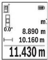
aWg uJ 0jslj
a a 1000000000000000000000000000000000000000000
j0jol jdo oog jds g0s1 s0,5 s
gigi dol, gwh jg oIgJdIaIgIjIgJyjlqilgJlo
.
daa JJgW G0s1s Jwj Kwulao
joljglj dawg jol [5] (5)
.
golj g jgb 4 min j1 w dwwg ojl
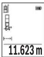
.8g 10
abw sJ 0jJl
.1sUlaJlJ 1bWgJsOjJdJ
ojsljgbg jol silo pww wuw yI golggbjc
Joo. Jio 0o oj g jg jol g jn dol j jg j
.□sij Go Sawgabw 5jS ojl sll jol laj JsS ojl sll sgo
656|wJ
GooJnJwJgDdOJyUgSgOjJlJd. gW dws Jsgs Jgb uabwogSgOjJlJyJu W dss JnuLyIqI SdW GooJnuWg .JlsJgUnSbSgOjJslSloJd.o
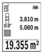
pss ojlsl
□psjS ojl. sU l
(2)doSgJwJ [+] (6)doJwW .sI S Jai Ij
]Func.
l0 ojlsl /o jlsjg
.
ojl jil jS g
:JUJUJgBwGjU
Sj 0jdl jd Ssawo"abw sJg oJdl" jb b wI J
aaw
c01g0daw dawlaoaaw.duoJlu[+] (6) daS
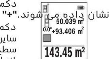
S oJl j Jw [] (5) 0jI aS S OJl" wIw I J baw .gaw jale gbw wu w paoa d. abw gJsi Jw
Jy Jg S 8000000000000000000000000000000000000000000000000000
Jus 1 j s oj 1 j 1s 1 s 1s 1s 1s 1s 1s 1s 1s 1s 1s 1s 1s 1s 1s 1s 1s 1s 1s 1s 1s 1s 1s 1s 1s 1s 1s

www.bosch-pt.com/serviceaddresses
664|
olswJas

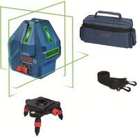


- Transport
- 34 | English
- Product description and specifications
- 36 | English
- Intended use
- Product features
- Display elements (selection)
- Technical data
- 40 | English
- Digital laser measure glm 50-27 CG glm 50-27 C
- Bluetooth® interface
- Transmitting data to other devices
- Further information can be found on the Bosch product page
- Activating the bluetooth® interface for transmitting data to a mobile device
- Deactivating the bluetooth® interface
- Assembly
- Inserting/changing the batteries
- Inserting/changing the lithium-ion battery pack (accessory)
- 42 | English
- Operation
- Charging the lithium-ion battery pack (accessory)
- Start-up
- Switching on/off
- Do not direct the laser beam at persons or animals and do not stare into the laser beam yourself (even from a distance)
- Measuring process
- Selecting the reference level (see figure b)
- 44 | English
- Settings" menu (see figure c)
- Measuring functions
- Help function (see figure d)
- Measuring length
- Continuous measurement
- Area measurement
- 46 | English
- Volume measurement
- Indirect distance measurement
- Indirect height measurement (see figure e)
- Double indirect height measurement (see figure f)
- Indirect length measurement (see figure g)
- Wall area measurement (see figure h)
- 48 | English
- Stake out function (see figure i)
- Grade measurement/digital spirit level
- Memory value display
- Deleting the memory
- 50 | English
- Adding/subtracting values
- Adding values
- Subtracting values
- Deleting measured values
- Practical advice
- General advice
- Influences on the measuring range
- Influences on the measurement result
- Checking accuracy and calibrating the grade measurement (see figure m)
- Accuracy check of the distance measurement
- 52 | English
- Working with the tripod (accessory)
- Belt clip (accessory) (see figure n)
- Error message
- Maintenance and service
- Maintenance and cleaning
- After-sales service and application service
- Great britain
- You can find further service addresses at
- Disposal
- Only for eu countries
- 54 | Français
- Battery packs/batteries
- François
- Transporte
- Trasporto
- Vervoer
- Subtrahera varde
- Raderamätvarden
- Kuljetus
- Metaopà
- Anoupon
- Móvo yia xωpec tnc ee
- Nakliye
- Preprava
- Szallitas
- Cpok cnyx6b1 n3dJIHn
- Ipeueheb kphtnuecknx OTka3OB n Oun6oHbIe deictbna nepcohana nn nnonb30BaTeTn
- Kpntepnn ppeenbhbix coctohhn
- I3o6paXeHHbIe coctabhbie yactn
- HnKaTopb1(Bbl6p)
- 372|Pycckn
- Texhnueckne dahhbie
- YcTaHOBka/3aMeHa nhtn-nohoro akkymyiatophoro 6NoKa (nphaiexhoctb)
- Pa6ota c nhctpymehtom
- 3apnKa nhtn-nohoro akkymyiatophoro 6noKa (nphaadjekhoctb)
- Bkiouehne 3neKtpOHnHcTpymeHTa
- BbI6Op nioockoctn otcutea (cm. pnc. b)
- Mehio «hactpoikn» (cm. pnc. c)
- Pexkmbi n3MepeHH
- Ppobepka touhctn KaHb6PoBkA npn H3MepeHHy rha kahnoha (cm. pnc. m)
- Ppobepka touhoctn H3MepeHna pacctoahna
- Tpahcnpopobka
- yTnnn3aun
- Tolbko dira ctpah-uehob ec
- 390|YkpaIHcbKa
- Akkymyiatophbie 6aTapeu/6aTapeuKn
- Ykpaihcbka
- Bka3iBkn 3 texhikn 6e3nekn
- 392|yKpaIHcBka
- 394|yKpaaiHcbKa
- BcTaHOBneHn/3amHa nii-iohhoro akymyiatophoro 6noka (npnaad)
- Ppoedpya bmipiobahha
- Bn6ip 6a30Boi nlouhhn (nhb. man. b)
- Mehio «hanaawtybahha» (dvb. man. c)
- 402|yKpaIHcbKa
- Функцьвимірібаhhя
- BmipioBaHHo6'Emy
- 404|yKpaaiHcbKa
- Henpme bmmpiobahhabctahi
- Iopdihhe hnprme bmipiobhahh bncotn (nb. man. f)
- Henpame bnmipiobahhdobxhhn (inb. man. g)
- Bmipobahnna nnooi ctih (nb. man. h)
- 406|YkpaIHcbka
- Pexn m po3mitkn (dhb. man. i)
- Bmipiobahha kytb haxnny/ncpobn batepnac
- Bido6paxeHH36epexeHx 3haueHb
- Ctnpahhbmictynam'ati
- DoaBaHHB/BiHimaHH3HaueHb
- 408|YkpaIHcbka
- Iodabahnhauehb
- Bidhimahnhaueheb
- CTnpaHHBumipAHX3HaueHb
- Bka3iBkn 0do p6oTH
- 3araanbHI Bka3iBKN
- Φaktopn bnjibby ha diana3OH bhmipiobahha
- Aektopn bnnby ha pe3ynbTaT bmipiobahh
- Ipebipka touhocti ta kani6pyBaHHn iin bmipobahk kyta haxny (nb. man. m)
- Ipebipka tohocti bmipobhabhabctahi
- 410|YkpaHcbka
- Po6ota 3i wtatbom (npnlaa)
- 3aTnckau dny kpinnehhn (npnaad) (nb. man. n)
- Iobidommehhnpo nomnkn
- Texhichne obcnyrobybahhaicepic
- Texhiche 06cnyrobyBaHHiaounueHHa
- Cepbicokcynbtaa3nntaHb3actocyBaHHA
- Ukpaha
- Adepeinihux cepbicnx uehtpib habeedeho hxkue
- Tpahcnprybahha
- 412|Ka3aK
- Ytunlizaia
- Jnne dna kpah ec
- Akymyitophi 6atapei/6atapenKn
- Jitiebo-iohhi
- Ka3ak
- Eypa3nЯ 3KoHOMNKaNbI k odafbiha (kejeh odafbiha) myse memnekette p aymafbihda konjahbiaibi
- Kayinci3dk hyckaynapbl
- Θhim xəhe kyat cnnattamacbl
- Makcatbi 6ObblHa kondany
- Kopcertinren kypamdbi 6oIwekterp
- Hnkaunna 3neMeHTTepi (tahamaibnbl)
- Texhnkaibik manimettep
- Kahama kawbiktbikbit enwey
- A)kahama 6nIKtki oiwey (ecypetih KapaHb13)
- Koc xahama 6niktikti eiwey (f cypetih kapaHbi3)
- 428|Ka3aK
- Kahama y3bIHdbIKtbl eniwey (g cypetih kapaHbi3)
- Ka6bipfaydaahbH onwey (hcypetih KapaHbI3)
- Tpaccnpeyfhknncbi (i cypetin kapaHb13)
- Eni ci tienwey/cahdbik dehre
- 430|Ka3aK
- KbI3MET kepcety optaibikTapbih6acka da mekehkahapbih mblha xepdeh KapaHbI3
- Tacbimaiay
- Kadere kapaty
- Tekkahaeoepei yuh
- AkkymyIaTOPnap/6aTapeIaIap
- Jihthn-nohbik
- Româna
- Instruţiuni de siguranta
- IocTaeHc/CMHaHaJIHTHeBO-HOHHaakymyLaTopHa6aTepeHn (phhajekhoct)
- Pa6ota
- 3apejdahe ha nhtnebo- nohha akymynatopha 6aTepe (nphajnxkhoct)
- 466|BbIrapckn
- Пускан eкпноатаць
- Bknioubahe n3KnIOuBaHe
- H3mepBaHe
- H36upaHe ha pepepehtha pabhnha (bx. qnr. b)
- 468|BbIrapckn
- Mehio „hactpoinkn"(bx.φnr.c)
- Функциизаизмервае
- Inhnpektho H3MepBaHe ha ibiixnha (bx. qnr. g)
- H3mepBaHe ha nnoi ha ctehh (bk. qnr. h)
- 472|BbIrapckn
- H3mepBaHe ha hakioh/unφpoba NH6eNa
- 3anaMeTeHcSTOHocTH
- 474|BbIrapckn
- H3tpnBaHe ha cbdbpxahheto ha nametta
- Cb6npaHe/n3BaXdaHe ha ctohocth
- Cb6npaHe hctohoctn
- N3BaXdaHe ha ctohoctn
- N3tpnBaHe ha N3MepeHH ctohocth
- yka3aHna 3a pa6ota
- 067n yka3aHna
- Φaktopn, bnhaeubbpxy dHaana30Ha ha H3MepBaHe
- Knnehtcka cnyk6a n kohcyntaun othoco ynoTpe6ata
- Былгаря
- 478|BbIrapckn
- Tpahcnptnpahe
- Бракуванe
- Cama 3a ctpanh ot ec
- AkymylaTopn6aTepn/6aTepn
- Jihthebo-nohhn
- Makedohckn
- Бeзб endochn hanomehn
- Ynotpe6a
- Ponhebe ha nhtym-johcknot 6aTepcKn naket (onpema)
- Ctabahe bo ynotpe6a
- Bknyybabe/ncknyybabe
- Ppoechamepebe
- H36upahe ha pepepehtho hnbo (bndn cinka b)
- Mehn ,noctabkn" (bnhn cinka c)
- 490 Makedohckn
- Mephhyhkch
- Hnpektho mepebe ha patojahnja
- Inhinpektho mepehe ha bncnha (bndn cnka e)
- B)дбоьно индпектно мереbbe ha bncnha (bndn cnka f)
- Inhnpektho mepehe ha donjxha (bnicnka g)
- Mepebe ha sndn nobpuhh (bnh cnka h)
- 494 Makedohckn
- Pnkaha 3auyBaHaTa bpehoct
- Dononhhtehh aapceha cepbnch moke da hajte noi
- Tpahcnopt
- Otctpahybabe
- 500 | Srpski
- Cama 3a 3emjnte oey
- Akymynatopcn 6aTeepn/6aTeepn
- Jinthym-johckn
- Srpski
- Uklanjanje dubreta
- Samo za eu-zemlje
- 520 | Slovenscina
- Akumulatori/baterije
- Slovenscina
- Varnostna opozorila
- Bluetooth® interfeiss
- Datparsutisana uz citamiekartam
- Darbs ar stativu (papildiederums)
- Jostas klipsis (piederums) (skatiet attelu n)
- Klumes zinojums
- Transportesana
- 600 | Lietuvi k
- Atbrivosanas no nolietotajiem izstradajumiem
- Tikai ek valstim
- Transportavimas
- Bluetooth 圆 _ 日 ijl digji
- Dolg dlal
- Piawlujluuwlg ajldo
- Ddaaal nglic jaojall
- Jai
- Ajysll 0o
- Gwj
- Igss
- Jg g ugs
- Olssji ojaiwi sjgo
- Lswj|j
- Sjs ojl sl sjslac
- Ugsjol
- l0 ojlsl /o jlsjg
- Olswjas
Brand : BOSCH
Model : GLM 5027 CG Professional
Category : Laser pointer